Embed Size (px)
Citation preview

Energy Storage at Duke Energy
Tom Fenimore, PE
Emerging Technology Office
September 18th, 2014

ETO Technology Screening Funnel
Initial Testing
Technology Screening
Technology Development
Field Testing
Deployment into Business unit
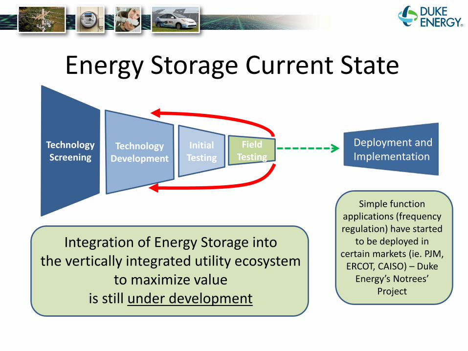
Energy Storage Current State
Initial Testing
Technology Screening
Technology Development
Field Testing
Deployment and Implementation
Simple function applications (frequency regulation) have started
to be deployed in certain markets (ie. PJM,
ERCOT, CAISO) – Duke Energy’s Notrees’
Project
Integration of Energy Storage into the vertically integrated utility ecosystem
to maximize value is still under development

Energy Storage Benefits Generation T & D End User
Frequency Regulation Defer System Upgrades Provide Back Up Power Renewable Smoothing Improve Reliability Utilize lower retail rates
Energy Shifting Renewable Smoothing
Spinning and Non-spinning Reserves
Improve Power Quality (Volt / VAR management)
Limit Peaker Plant Builds
Through pilots we understand…
Capital Costs O & M Costs Installation Hurdles Operational Issues Value Streams
…to develop
Business models Regulatory models Understand benefits
4

How did Duke Energy
get here?

Over 25
6
Five differe
locatio
>25
6Six unique demonstration projects
installed
functions
Six different
battery chemistries tested
5nt
ns
How did Duke Energy
get here?
Benefit: Connected on: • Transmission • Distribution • Customer • With renewables
Diverse chemistries in different capacities
kW
kWh
200 400 600 800
200
400
600
800
25kW/25kWh Lithium Ion
250kW/750kWh Lithium Polymer
36MW/24MWh Advanced Lead Acid
200kW/500kWh Li Iron Phosphate
200kW/500kWh Sodium Nickel
75kW/42kWh Lithium Titanate
How do
SIZE LOCATION CHEMISTRY FUNCTION
enable value?
on the grid demonstrated

Notrees Wind Farm Project Notrees, TX
Major system components: • 36 MW / 24 MWh • Xtreme Power Advanced Lead Acid Technology • Co-located at site of 156 MW Wind Farm in Notrees,
Texas • Began commercial operation in December 2012 • 50:50 Cost share with DOE
Applications being tested
1 – Ancillary Services: participating in a series of ERCOT (Texas ISO) market tests to learn how to structure an efficient market that enables energy storage to provide ancillary services to the grid.
2 – Energy Shifting: Charging and discharging to maximize the value of energy delivered to the grid based on timing.
3-Avoiding Wind Curtailment : Using storage to store wind energy in order to avoid orders to cease providing power to the grid.

Example: Texas and ERCOT (Electric Reliability Council of Texas)
• Texas has seen a large amount of wind growth over the past 10 years.
• This has the created the need for fast responding resources such as energy storage to help stabilize the grid
Texas alone has more wind than France.
15

Example of Daily Wind Output in ERCOT
Wind is highly variable (the graph to the right shows a daily wind profile in Texas) which makes balancing supply and demand very difficult. Fast responding resources such as battery energy storage can help solve this problem.
16

Example of Battery’s Output and Response Time Duke Energy’s 36 MW / 24 MWh battery charging and discharging based off market signals to help with grid stability
17
Discharging
Charging

McAlpine Energy Storage System McAlpine Creek Retail Substation, Charlotte, NC
Major system components: • 200 kW / 500 kWh system capacity • BYD battery and inverter system
• All components integrated within on container • Lithium-iron-phosphate battery (BYD)
Interconnection: • Located on a 24 kV distribution circuit • Interconnected immediately outside of the substation • Adjacent to 50 kW solar facility on McAlpine test circuit
BYD battery 200 kW/500 kWh LiFePO4
Inverter/Controls Integrated within one container
System attributes • In service 4Q 2012
x
• Interconnected next to a 50 kW solar facility in a planned islandable micro-grid scheme that will use the battery for grid frequency/voltage regulation.
Applications being tested
1 – consolidated inverter/battery construction at a low price
2 – energy shifting applications a) dispatched based on schedule, local load peaks, etc
3 – integration with solar in a microgrid a) will be configured with switches, solar, and load to create
an autonomous microgrid that disconnects from the circuit
4 – solar output smoothing/firming

Solar
Islandable Microgrid Schematic
SS McAlpine Crk.
Retail
Sola r
Battery
120/208 V
480/277 V
24 kV
24 kV
Ckt 2
414
Electronic switch w/ DG protective settings:
“DG Switch” Normally Closed
75 kVA (3 x 25 kVA)
Fire Station
200 kVA 500 kWh
50 kW
Electronic switch to disconnect from grid: “Islanding Switch” Normally Closed
500 kVA
Equipment Legend Microgrid
Controller
Manual Disconnect
Point of common coupling
Existing
New
Sense & Control
AC
DC
AC
DCInve
rter
Inve
rter
19

Microgrid Controller HMI

Rankin Energy Storage System Rankin Ave. Retail Substation, Mount Holly, NC
Major system components: • 402 kW / 282 kWh system capacity • FIAMM sodium nickel chloride battery
• 12 Zebra bus batteries connected in parallel • 1.25 MVA S&C Electric Company Inverter (SMS)
Interconnection: • Located on a 12.47 kV distribution circuit • Interconnected immediately outside of the substation • Circuit contains a 1.2 MW solar facility ~3 miles away
System attributes • Installed Dec 2011, in service Mar 2012
• Remotely operable
• ZEBRA bus batteries by FIAMM for stationary application development
• Contains fiber connection to substation relaying; no connection to the solar facility on the circuit
1000 kVA transformer Auxiliary power load center Steps up 480 V inverter 120V/240V service output to 12.47 kV
Battery container Inverter/Controls 402 kW/282 kWh NaNiCl Storage Management System (SMS) batteries (12 cells) 1.25 MVA capacity/1.0 MVAR capacity
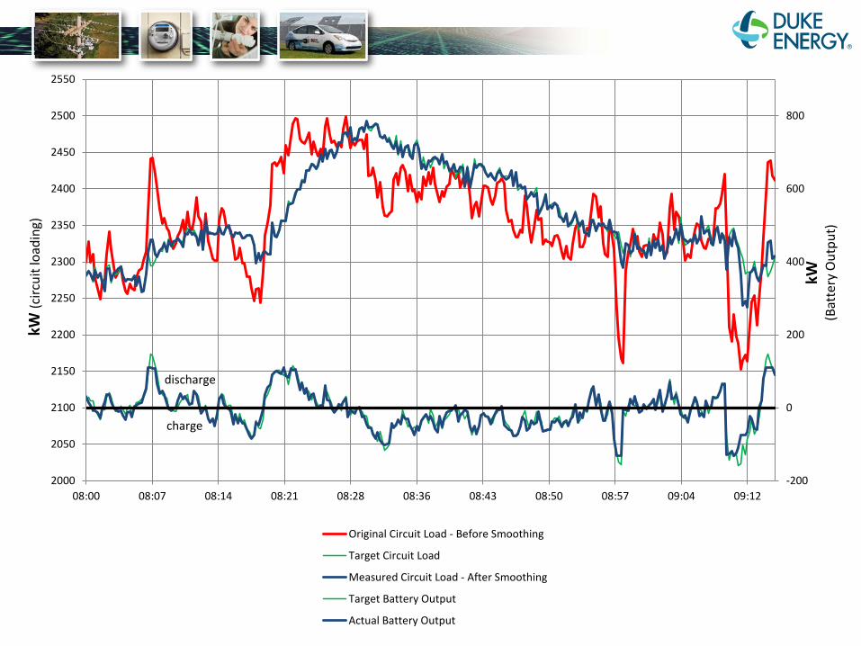
Applications being tested
1 – centralized solar-induced power swing mitigation a) senses substation real power loading and uses battery to
“smooth” rapid ramp rates caused by cloud-induced solar intermittency b) no direct connection to the solar – designed to smooth
power swings from multiple dispersed solar sites on a circuit
2 – active VAR/power factor management
3 – combined watt/VAR voltage control a) compensation for rapid solar-induced voltage changes
kW (c
ircui
t loa
ding
)
(Bat
tery
Out
put)
2550
2500 800
2450
2400 600
2350
discharge
charge
2300 400
2250
2200 200
kW
2150
2100 0
2050
2000 -200 08:00 08:07 08:14 08:21 08:28 08:36 08:43 08:50 08:57 09:04 09:12
Original Circuit Load - Before Smoothing
Target Circuit Load
Measured Circuit Load - After Smoothing
Target Battery Output
Actual Battery Output

Marshall Energy Storage System Marshall Steam Station, Sherrills Ford, NC
Major system components: • 750 kWh / 250 kW system capacity • Kokam Superior Lithium Polymer Batteries • 1.25 MVA S&C Electric Company Inverter (SMS)
Interconnection: • Located on a 12.47 kV distribution circuit • Separate but adjacent medium-voltage interconnection
from 1.0 MW solar facility • Located at the end of a distribution feeder
System attributes
• Installed May 2012, in service July 2012
• Remotely operable
• Battery and inverter independently sourced (both vendors to Duke)
• Located at the Marshall solar test site where multiple solar technologies are being field tested on a sealed coal-ash landfill
1000 kVA transformer Inverter/Controls Steps up 480 V inverter Storage Management System (SMS) output to 12.47 kV 1.25 MVA capacity/1.0 MVAR capacity
Battery container 750 kWh/250 kW Lithium Polymer Includes Batt. Mgt. System
1.2 MW solar facility
Applications being tested 1 – energy shifting a) for system-level arbitrage b) for local operational constraint management c) based on forward-looking economic algorithm
2 – solar output smoothing and firming a) for local feeder voltage management b) solar-induced power swing mitigation
3 – active VAR/power factor management 4 – combined algorithms / optimization a) combined energy shifting and smoothing algorithm b) use of distributed logic with economic, substation, and
local input parameters

Battery Clay Terrace Energy Storage System Clay Terrace Mall, IN
Major system components: • 75 kW / 42 kWh system capacity • Toshiba lithium titanate battery • 10 kW roof-mounted solar • Eaton 50 kW, Siemens 3.3 kW PEV charging stations
Interconnection: • Behind a commercial meter (customer sited) • Interconnected at 480V, 3-phase transformer • Located in the parking lot of a shopping mall
System attributes • Installed 3Q 2012, in service 4Q 2012
• Designed to manage and optimize the combined energy profile of solar, PEV charging, and storage.
75 kW / 42 kWh Toshiba Li-Titinate 10 kW solar roof-top
PEV DC Fast charging station 50 kW Eaton unit
Level 2 PEV charging station J1772 up to 3.3 kW charging
Applications being tested
1 – active management of combined solar, storage and PEV charging a) testing energy management system and sizing of a
behind-the-meter system
2 – energy shifting
3 – customer-sited installation aspects

Battery Responding to DC Charge Event
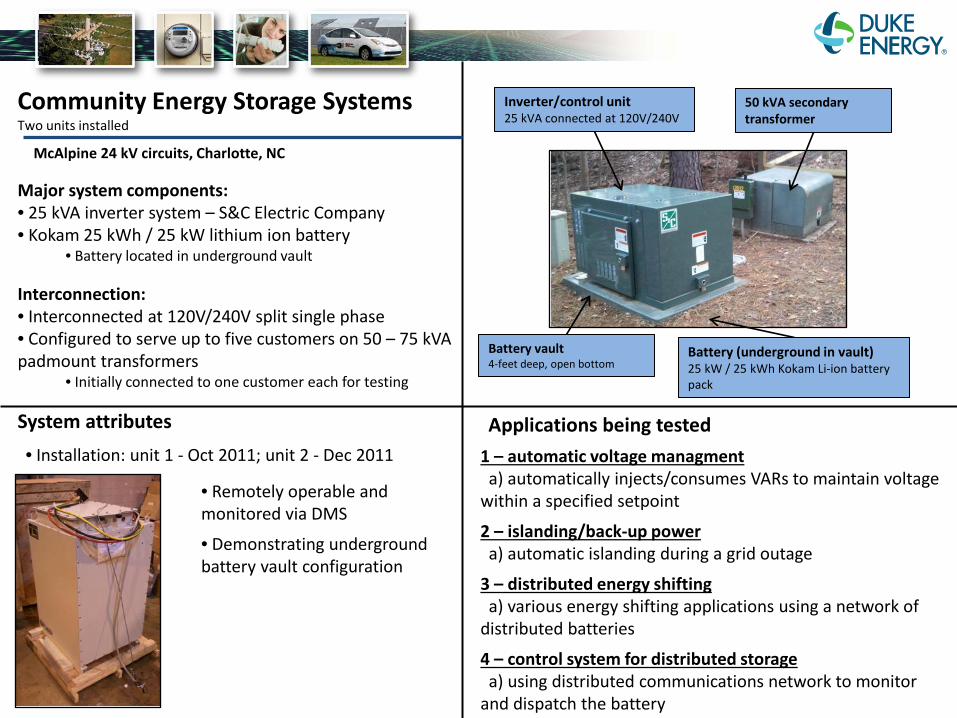
Community Energy Storage Systems Two units installed
McAlpine 24 kV circuits, Charlotte, NC
Major system components: • 25 kVA inverter system – S&C Electric Company • Kokam 25 kWh / 25 kW lithium ion battery
• Battery located in underground vault
Interconnection: • Interconnected at 120V/240V split single phase • Configured to serve up to five customers on 50 – 75 kVA padmount transformers
• Initially connected to one customer each for testing
System attributes • Installation: unit 1 - Oct 2011; unit 2 - Dec 2011
• Remotely operable and monitored via DMS
• Demonstrating underground battery vault configuration
Inverter/control unit 50 kVA secondary 25 kVA connected at 120V/240V transformer
Battery vault Battery (underground in vault) 4-feet deep, open bottom 25 kW / 25 kWh Kokam Li-ion battery
pack
Applications being tested 1 – automatic voltage managment a) automatically injects/consumes VARs to maintain voltage
within a specified setpoint
2 – islanding/back-up power a) automatic islanding during a grid outage
3 – distributed energy shifting a) various energy shifting applications using a network of
distributed batteries
4 – control system for distributed storage a) using distributed communications network to monitor
and dispatch the battery

Need to Consider • Physical vs. Virtual Energy Storage • How will energy storage compete / work
together with: – Smart Invertors – Demand Response – Devices which perform autonomous frequency
regulation

Conclusions • The electric grid is changing: Electric generation is
becoming more “de-centralized” – moving closer to the end user
• Balancing supply and demand requires a highly interconnected ecosystem with constant communication between assets
• Understanding how energy storage can seamlessly be integrated in this ecosystem is still under development


![Duke Energy Emerging Technology Office · Duke Energy Emerging Technology Office ... Unscheduled Islanding Transition Microgrid Transitions ... + cpp: Integer [0..1]](https://img.pdfslide.us/doc/110x75/5ac0afc97f8b9a357e8bcb56/duke-energy-emerging-technology-office-energy-emerging-technology-office-unscheduled.jpg)