Embed Size (px)
Citation preview
BUILDING TECHNOLOGIES PROGRAM
Energy Renovations
HVACA Guide for Contractors to Share with Homeowners
PREPARED BY
Pacific Northwest National Laboratory
& Oak Ridge National Laboratory
August 2011
August 2011 • PNNL-20421
BUILDING AMERICA BEST PRACTICES SERIESVOLUME 14.
R

BUILDING AMERICA BEST PRACTICES SERIES
Energy Renovations
Volume 14: HVACA Guide for Contractors to Share with Homeowners
Prepared by
Pacific Northwest National Laboratory
Program Manager: Michael C. Baechler
Theresa L. Gilbride, Michael C. Baechler, Marye G. Hefty, and James R. Hand
and
Oak Ridge National Laboratory
Pat M. Love
August 2011
Prepared for the U.S. Department of Energy Building America Program
PNNL-20421Pacific Northwest National Laboratory Richland, Washington 99352Contract DE-AC05-76RLO 1830
This report was prepared as an account of work sponsored by an agency of the
United States Government. Neither the United States Government nor any agency
thereof, nor Battelle Memorial Institute, nor any of their employees, makes any
warranty, express or implied, or assumes any legal liability or responsibility for the
accuracy, completeness, or usefulness of any information, apparatus, product, or
process disclosed, or represents that its use would not infringe privately owned rights.
Reference herein to any specific commercial product, process, or service by trade
name, trademark, manufacturer, or otherwise does not necessarily constitute or imply
its endorsement, recommendation, or favoring by the United States Government or
any agency thereof, or Battelle Memorial Institute. The views and opinions of authors
expressed herein do not necessarily state or reflect those of the United States
Government or any agency thereof.

Preface
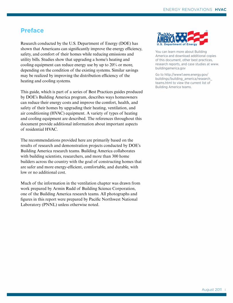
Research conducted by the U.S. Department of Energy (DOE) has shown that Americans can significantly improve the energy efficiency, safety, and comfort of their homes while reducing emissions and utility bills. Studies show that upgrading a home’s heating and cooling equipment can reduce energy use by up to 20% or more, depending on the condition of the existing systems. Similar savings may be realized by improving the distribution efficiency of the heating and cooling systems.
This guide, which is part of a series of Best Practices guides produced by DOE’s Building America program, describes ways homeowners can reduce their energy costs and improve the comfort, health, and safety of their homes by upgrading their heating, ventilation, and air conditioning (HVAC) equipment. A variety of types of heating and cooling equipment are described. The references throughout this document provide additional information about important aspects of residential HVAC.
The recommendations provided here are primarily based on the results of research and demonstration projects conducted by DOE’s Building America research teams. Building America collaborates with building scientists, researchers, and more than 300 home builders across the country with the goal of constructing homes that are safer and more energy-efficient, comfortable, and durable, with low or no additional cost.
Much of the information in the ventilation chapter was drawn from work prepared by Armin Rudd of Building Science Corporation, one of the Building America research teams. All photographs and figures in this report were prepared by Pacific Northwest National Laboratory (PNNL) unless otherwise noted.
R
You can learn more about Building America and download additional copies of this document, other best practices, research reports, and case studies at www.buildingamerica.gov
Go to http://www1.eere.energy.gov/buildings/building_america/research_teams.html to view the current list of Building America teams.
August 2011 i
i
ENERGY RENOVATIONS HVAC
Contents
Preface ................................................................................................................. i
1.0 Introduction .................................................................................................1
1.1 Building America’s Whole-House Approach ........................1
1.2 The Home Performance Energy Assessment ......................2
1.3 Space Heating and Cooling ........................................................3
1.4 Building Permits and Codes .......................................................3
2.0 Heating Systems ......................................................................................5
2.1 Furnaces ............................................................................................8
2.1.1 Furnace Efficiency ..............................................................8
2.1.2 Repair or Replace? ............................................................10
2.1.3 Ducts ..................................................................................... 12
2.2 Electric Heaters ............................................................................. 15
2.2.1 Electric Central Furnaces ............................................... 15
2.2.2 Room Heaters .................................................................... 15
2.2.3 Zoning .................................................................................... 16
2.3 Heat Pumps ..................................................................................... 17
2.3.1 Central Air-Source Heat Pumps ..................................... 18
2.3.2 Ductless Heat Pumps ........................................................ 19
2.3.3 Ground-Source Heat Pumps .........................................20
2.4 Boilers and Hydronic Heating ................................................. 23
2.4.1 Steam and Hot Water Radiators ................................ 23
2.4.2 Radiant Floor Heating .................................................... 24
2.4.3 Repair or Replace ............................................................. 24
2.5 Wood and Pellet Heating .......................................................... 25
2.6 Solar Heating ................................................................................. 26
2.6.1 Passive Solar Heating ....................................................... 27
2.6.2 Active Solar Heating ........................................................ 28
ii August 2011
ENERGY RENOVATIONS HVAC
3.0 Cooling Systems .................................................................................. 29
3.1 Central Air Conditioning .......................................................... 33
3.1.1 Repair or Replace? ...........................................................34
3.2. Room Air Conditioning ..............................................................36
3.3 Heat Pumps ..................................................................................36
3.3.1 Central- and Ground-Source Heat Pumps ..............36
3.3.2 Ductless Heat Pumps ......................................................36
3.3.3 Absorption Heat Pumps ................................................ 37
3.4 Evaporative Coolers .................................................................... 38
3.5 Radiant Cooling ............................................................................39
3.6 Dehumidifiers .............................................................................. 40
3.7 Natural Cooling Strategies .......................................................41
3.7.1 Fans and Ventilation for Cooling .................................41
3.7.2 Passive Cooling ................................................................44
4.0 Ventilation ............................................................................................... 47
4.1 Exhaust-Only Ventilation ..........................................................49
4.2 Supply-Only Ventilation ...........................................................50
4.3 Balanced Systems......................................................................... 51
4.4 “Semi-Balanced” System ............................................................. 51
5.0 The Home Performance Energy Assessment ............................ 53
5.1 Certified Energy Contractors .................................................... 53
5.2 The Energy Assessment Process.............................................54
5.2.1 Step 1. The Energy Performance Assessment ......54
5.2.2 Step 2. Making Energy-Efficiency Upgrades ......... 55
5.2.3 Step 3. Testing Out .......................................................... 55
References .....................................................................................................56
Definitions ..................................................................................................... 58
Building America Teams ............................................................................59
August 2011 iii
iii
ENERGY RENOVATIONS HVAC

1.0 Introduction
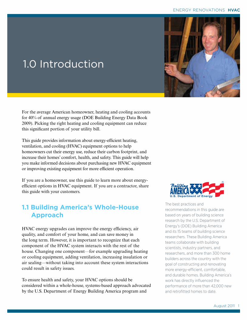
For the average American homeowner, heating and cooling accounts for 40% of annual energy usage (DOE Building Energy Data Book 2009). Picking the right heating and cooling equipment can reduce this significant portion of your utility bill.
This guide provides information about energy-efficient heating, ventilation, and cooling (HVAC) equipment options to help homeowners cut their energy use, reduce their carbon footprint, and increase their homes’ comfort, health, and safety. This guide will help you make informed decisions about purchasing new HVAC equipment or improving existing equipment for more efficient operation.
If you are a homeowner, use this guide to learn more about energy-efficient options in HVAC equipment. If you are a contractor, share this guide with your customers.
1.1 Building America’s Whole-House Approach
HVAC energy upgrades can improve the energy efficiency, air quality, and comfort of your home, and can save money in the long term. However, it is important to recognize that each component of the HVAC system interacts with the rest of the house. Changing one component—for example upgrading heating or cooling equipment, adding ventilation, increasing insulation or air sealing—without taking into account these system interactions could result in safety issues.
To ensure health and safety, your HVAC options should be considered within a whole-house, systems-based approach advocated by the U.S. Department of Energy Building America program and
The best practices and recommendations in this guide are based on years of building science research by the U.S. Department of Energy’s (DOE) Building America and its 15 teams of building science researchers. These Building America teams collaborate with building scientists, industry partners, and researchers, and more than 300 home builders across the country with the goal of constructing and renovating more energy-efficient, comfortable, and durable homes. Building America’s work has directly influenced the performance of more than 42,000 new and retrofitted homes to date.
R
August 2011 1
1
ENERGY RENOVATIONS HVAC
building scientists across the country. This whole-house approach, which is based on years of research in thousands of real homes, takes into account how one change in a home’s HVAC system can affect the energy efficiency, comfort, durability, health, and safety of the whole house.
To implement this whole-house approach and and to confirm real energy-use improvements, Building America recommends that HVAC home energy upgrades start with a home performance energy assessment.
1.2 The Home Performance Energy Assessment
The home energy assessment is conducted within the context of a whole-house system-based approach to home performance to ensure homeowner health and safety as well as energy performance. The home energy assessment should be conducted by a contractor who is trained in building science principles, such as those described in the DOE Guidelines for Home Energy Upgrade Professionals and the U.S. Environmental Protection Agency’s Healthy Indoor Environment Protocols for Home Energy Upgrades, as well as those recommended by Home Performance with ENERGY STAR, the Building Performance Institute (BPI) standards, state weatherization programs, or accredited college program recommendations.
The assessment (also known as an audit) consists of three steps: testing in, conducting the work, and testing out. In the test-in step, the contractor interviews homeowners about any concerns they have about their HVAC system, such as comfort complaints or high utility bills; conducts safety tests and tests for air leakage in the ducts and whole house; and visually inspects for insulation levels and signs of mold or moisture problems. The contractor uses energy software to analyze the results and gives this report to the homeowner, along with a prioritized list of recommendations. The homeowner works with the energy performance contractor or HVAC contractor to determine a scope of work and have the work completed. In the test-out step, the completed work is evaluated with safety tests and visual inspections.
For more information on what you can learn from a home performance energy assessment and why it is a good idea to have one, see Chapter 5 of this report.
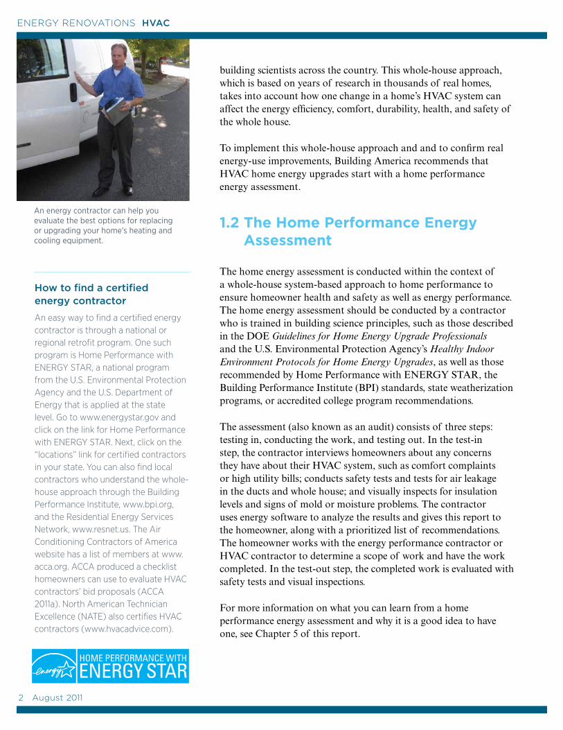
How to find a certified energy contractor
An easy way to find a certified energy contractor is through a national or regional retrofit program. One such program is Home Performance with ENERGY STAR, a national program from the U.S. Environmental Protection Agency and the U.S. Department of Energy that is applied at the state level. Go to www.energystar.gov and click on the link for Home Performance with ENERGY STAR. Next, click on the “locations” link for certified contractors in your state. You can also find local contractors who understand the whole-house approach through the Building Performance Institute, www.bpi.org, and the Residential Energy Services Network, www.resnet.us. The Air Conditioning Contractors of America website has a list of members at www.acca.org. ACCA produced a checklist homeowners can use to evaluate HVAC contractors' bid proposals (ACCA 2011a). North American Technician Excellence (NATE) also certifies HVAC contractors (www.hvacadvice.com).
An energy contractor can help you evaluate the best options for replacing or upgrading your home’s heating and cooling equipment.
2 August 2011
ENERGY RENOVATIONS HVAC
1.3 Space Heating and Cooling
Replacing or upgrading your HVAC system offers excellent opportunities for cutting your utility bills and improving your home’s indoor air quality, comfort, and durability. Your certified energy contractor or HVAC contractor can help you determine which heating and cooling options are right for you. Talk to your contractor about fuel types and prices in your region. Your contractor can help you determine whether it is safe and cost-effective to repair and improve the HVAC equipment you already have or to replace or supplement it with new, more efficient equipment.
The contractor can also provide advice about other ways to improve the energy efficiency of your home, such as by sealing air leaks and adding insulation. These efficiency improvements are often the most cost-effective means of saving energy in the long run.
If you decide to replace an existing heating or cooling system, one option is to replace the existing equipment with an updated model of the same type, especially if the distribution system (ducts or radiators) is still good. However, this may not be the most efficient heating and cooling option for your money.
See the following chapters for information and recommendations on the many heating, cooling, and ventilation options available today.
1.4 Building Permits and Codes
Your contractor will check with your local building department to determine what building codes apply and to obtain any needed permits. Depending on the extent of your project, you may need a building permit and plumbing, electrical, or mechanical permits. State or local building codes, including health, safety, and energy codes, may apply to building alterations and additions.
Your local utilities are a good resource for equipment incentives, rebates, and low-interest loan programs, as well as listings of local licensed contractors and details on any utility requirements that might affect your project. Underwriters Laboratory is responsible for third-party testing of HVAC equipment, so look for the Underwriters Laboratory seal when purchasing equipment (ANSI 2011).
Federal, State, and Utility Incentive Programs
Many local, state, and federal entities offer grants and tax credits for energy-efficient home improvements. Check with your local utility or city, or check the DOE-sponsored Database of State Incentives for Renewables and Efficiency (DSIRE) at www.dsireusa.org.
This site is frequently updated and is a wealth of information, organized by state, regarding state, local, utility, and federal incentives, tax credits, and rebates for renewable energy and energy-efficiency upgrades.
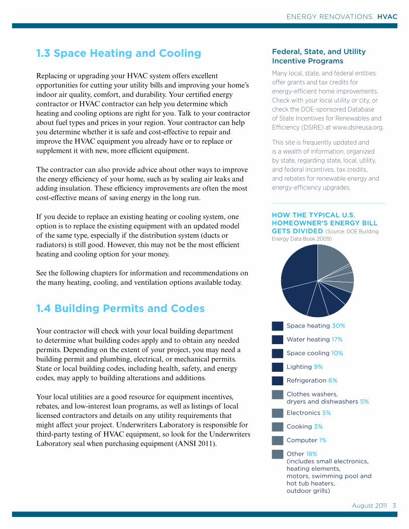
Space heating 30%
Water heating 17%
Space cooling 10%
Lighting 9%
Refrigeration 6%
Clothes washers, dryers and dishwashers 5%
Electronics 5%
Cooking 3%
Computer 1%
Other 18% (includes small electronics, heating elements, motors, swimming pool and hot tub heaters, outdoor grills)
Space heating 30%
Water heating 17%
Space cooling 10%
Lighting 9%
Refrigeration 6%
Clothes washers, dryers and dishwashers 5%
Electronics 5%
Cooking 3%
Computer 1%
Other 18% (includes small electronics, heating elements, motors, swimming pool and hot tub heaters, outdoor grills)
HOW THE TYPICAL U.S. HOMEOWNER'S ENERGY BILL GETS DIVIDED (Source: DOE Building Energy Data Book 2009)
August 2011 3
3
ENERGY RENOVATIONS HVAC

4 August 2011
ENERGY RENOVATIONS HVAC
Heating Fuel Costs
Costs for heating oil and natural gas have varied greatly in recent years. For an apples-to-apples comparison of heating types by cost and percent efficiency, see the Heating Fuel Comparison Calculator developed by the U.S. DOE Energy Information Administration (EIA). Fuel costs are tied to databases that update weekly or daily (www.eia.doe.gov/neic/experts/heatcalc.xls).
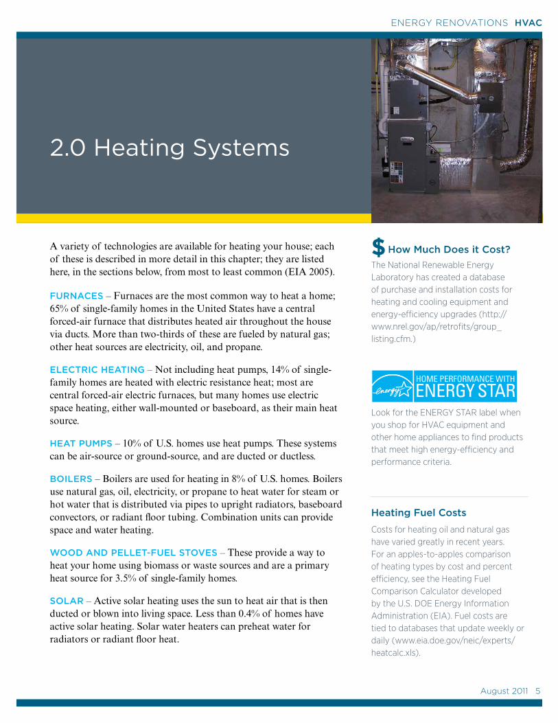
2.0 Heating Systems
A variety of technologies are available for heating your house; each of these is described in more detail in this chapter; they are listed here, in the sections below, from most to least common (EIA 2005).
FURNACES – Furnaces are the most common way to heat a home; 65% of single-family homes in the United States have a central forced-air furnace that distributes heated air throughout the house via ducts. More than two-thirds of these are fueled by natural gas; other heat sources are electricity, oil, and propane.
ELECTRIC HEATING – Not including heat pumps, 14% of single-family homes are heated with electric resistance heat; most are central forced-air electric furnaces, but many homes use electric space heating, either wall-mounted or baseboard, as their main heat source.
HEAT PUMPS – 10% of U.S. homes use heat pumps. These systems can be air-source or ground-source, and are ducted or ductless.
BOILERS – Boilers are used for heating in 8% of U.S. homes. Boilers use natural gas, oil, electricity, or propane to heat water for steam or hot water that is distributed via pipes to upright radiators, baseboard convectors, or radiant floor tubing. Combination units can provide space and water heating.
WOOD AND PELLET-FUEL STOVES – These provide a way to heat your home using biomass or waste sources and are a primary heat source for 3.5% of single-family homes.
SOLAR – Active solar heating uses the sun to heat air that is then ducted or blown into living space. Less than 0.4% of homes have active solar heating. Solar water heaters can preheat water for radiators or radiant floor heat.
$The National Renewable Energy Laboratory has created a database of purchase and installation costs for heating and cooling equipment and energy-efficiency upgrades (http://www.nrel.gov/ap/retrofits/group_listing.cfm.)
Look for the ENERGY STAR label when you shop for HVAC equipment and other home appliances to find products that meet high energy-efficiency and performance criteria.
How Much Does it Cost?
August 2011 5
5
ENERGY RENOVATIONS HVAC
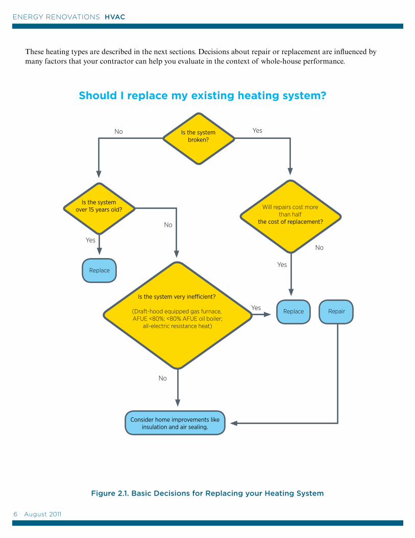
These heating types are described in the next sections. Decisions about repair or replacement are influenced by many factors that your contractor can help you evaluate in the context of whole-house performance.
Yes
No
Should I replace my existing heating system?
YesNo
Yes
Consider home improvements like insulation and air sealing.
No
Yes
Replace
Is the system broken?
Is the system very inefficient?
(Draft-hood equipped gas furnace, AFUE <80%; <80% AFUE oil boiler;
all-electric resistance heat)
Is the system over 15 years old? Will repairs cost more
than half the cost of replacement?
No
Repair
Replace
Figure 2.1. Basic Decisions for Replacing your Heating System
6 August 2011
ENERGY RENOVATIONS HVAC
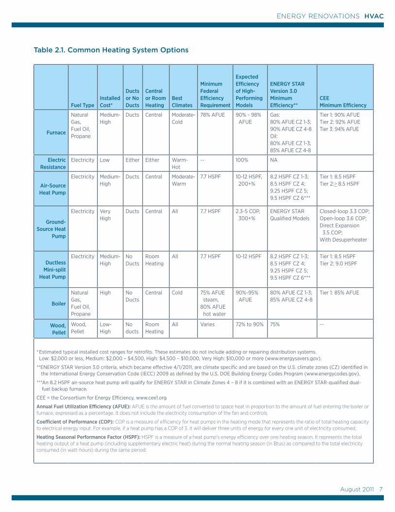
Table 2.1. Common Heating System Options
Fuel TypeInstalled Cost*
Ducts or No Ducts
Central or Room Heating
Best Climates
Minimum Federal Efficiency Requirement
Expected Efficiency of High-Performing Models
ENERGY STAR Version 3.0 Minimum Efficiency**
CEE Minimum Efficiency
Furnace
Natural Gas, Fuel Oil, Propane
Medium-High
Ducts Central Moderate-Cold
78% AFUE 90% - 98% AFUE
Gas: 80% AFUE CZ 1-3; 90% AFUE CZ 4-8 Oil: 80% AFUE CZ 1-3; 85% AFUE CZ 4-8
Tier 1: 90% AFUE Tier 2: 92% AFUE Tier 3: 94% AFUE
Electric Resistance
Electricity Low Either Either Warm-Hot
-- 100% NA
Air-Source Heat Pump
Electricity Medium-High
Ducts Central Moderate-Warm
7.7 HSPF 10-12 HSPF, 200+%
8.2 HSPF CZ 1-3; 8.5 HSPF CZ 4; 9.25 HSPF CZ 5; 9.5 HSPF CZ 6***
Tier 1: 8.5 HSPF Tier 2:>_ 8.5 HSPF
Ground-Source Heat
Pump
Electricity Very High
Ducts Central All 7.7 HSPF 2.3-5 COP, 300+%
ENERGY STAR Qualified Models
Closed-loop 3.3 COP; Open-loop 3.6 COP; Direct Expansion 3.5 COP; With Desuperheater
Ductless Mini-split
Heat Pump
Electricity Medium-High
No Ducts
Room Heating
All 7.7 HSPF 10-12 HSPF 8.2 HSPF CZ 1-3; 8.5 HSPF CZ 4; 9.25 HSPF CZ 5; 9.5 HSPF CZ 6***
Tier 1: 8.5 HSPF Tier 2: 9.0 HSPF
Boiler
Natural Gas, Fuel Oil, Propane
High No Ducts
Central Cold 75% AFUE steam, 80% AFUE hot water
90%-95% AFUE
80% AFUE CZ 1-3; 85% AFUE CZ 4-8
Tier 1: 85% AFUE
Wood, Pellet
Wood, Pellet
Low-High
No ducts
Room Heating
All Varies 72% to 90% 75% --
* Estimated typical installed cost ranges for retrofits. These estimates do not include adding or repairing distribution systems. Low: $2,000 or less, Medium: $2,000 – $4,500, High: $4,500 – $10,000, Very High: $10,000 or more (www.energysavers.gov).
**ENERGY STAR Version 3.0 criteria, which became effective 4/1/2011, are climate specific and are based on the U.S. climate zones (CZ) identified in the International Energy Conservation Code (IECC) 2009 as defined by the U.S. DOE Building Energy Codes Program (www.energycodes.gov).
***An 8.2 HSPF air-source heat pump will qualify for ENERGY STAR in Climate Zones 4 – 8 if it is combined with an ENERGY STAR-qualified dual- fuel backup furnace.
CEE = the Consortium for Energy Efficiency, www.cee1.org
Annual Fuel Utilization Efficiency (AFUE): AFUE is the amount of fuel converted to space heat in proportion to the amount of fuel entering the boiler or furnace; expressed as a percentage. It does not include the electricity consumption of the fan and controls.
Coefficient of Performance (COP): COP is a measure of efficiency for heat pumps in the heating mode that represents the ratio of total heating capacity to electrical energy input. For example, if a heat pump has a COP of 3, it will deliver three units of energy for every one unit of electricity consumed.
Heating Seasonal Performance Factor (HSPF): HSPF is a measure of a heat pump’s energy efficiency over one heating season. It represents the total heating output of a heat pump (including supplementary electric heat) during the normal heating season (in Btus) as compared to the total electricity consumed (in watt-hours) during the same period.
August 2011 7
7
ENERGY RENOVATIONS HVAC
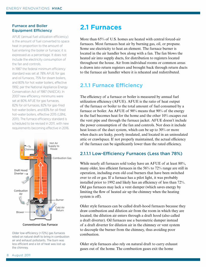
CombustionAir
Draft Hood/ Diverter
2.1 Furnaces
More than 65% of U.S. homes are heated with central forced-air furnaces. Most furnaces heat air by burning gas, oil, or propane. Some use electricity to heat an element. The furnace burner is located in the air handler box along with a fan. The fan blows the heated air into supply ducts, for distribution to registers located throughout the house. Air from individual rooms or common areas is drawn into return registers and brought back through return ducts to the furnace air handler where it is reheated and redistributed.
2.1.1 Furnace Efficiency
The efficiency of a furnace or boiler is measured by annual fuel utilization efficiency (AFUE). AFUE is the ratio of heat output of the furnace or boiler to the total amount of fuel consumed by a furnace or boiler. An AFUE of 90% means that 90% of the energy in the fuel becomes heat for the home and the other 10% escapes out the vent pipe and through the furnace jacket. AFUE doesn’t include the power consumption of the fan and controls. Nor does it include heat losses of the duct system, which can be up to 30% or more when ducts are leaky, poorly insulated, and located in an uninsulated attic or crawlspace. If not properly maintained, the actual efficiency of the furnace can be significantly lower than the rated efficiency.
2.1.1.1 Low-Efficiency Furnaces (Less than 78%)
While nearly all furnaces sold today have an AFUE of at least 80%, many older, less efficient furnaces in the 56% to 72% range are still in operation, including even old coal burners that have been switched over to oil or gas. If a furnace has a pilot light, it was probably installed prior to 1992 and likely has an efficiency of less than 72%. Old gas furnaces may lack a vent damper (which saves energy by limiting the flow of heated air up the chimney when the heating system is off).
Older style furnaces can be called draft-hood furnaces because they draw combustion and dilution air from the room in which they are located; the dilution air enters through a draft hood (also called a draft diverter). Oil furnaces use a barometric damper instead of a draft diverter for dilution air in the chimney or vent system to decouple the burner from the chimney, thus avoiding poor combustion.
Older style furnaces also rely on natural draft to carry exhaust gases out of the home. The combustion gases exit the home
Furnace and Boiler Equipment Efficiency
AFUE (annual fuel utilization efficiency) is the amount of fuel converted to space heat in proportion to the amount of fuel entering the boiler or furnace; it is expressed as a percentage. It does not include the electricity consumption of the fan and controls. In 1987 the federal minimum efficiency standard was set at 78% AFUE for gas and oil furnaces, 75% for steam boilers, and 80% for hot water boilers, effective 1992, per the National Appliance Energy Conservation Act of 1987 (NAECA). In 2007 new efficiency minimums were set at 80% AFUE for gas furnaces, 82% for oil furnaces, 82% for gas-fired hot-water boilers, and 83% for oil-fired hot-water boilers, effective 2015 (LBNL 2011). The furnace efficiency standard is scheduled to be revised in 2011, with new requirements becoming effective in 2016.
Older low-efficiency (<72%) gas furnaces relied on natural draft to bring in combustion air and exhaust pollutants. The burn was less efficient and a lot of heat was lost up the chimney.
8 August 2011
ENERGY RENOVATIONS HVAC
Burner
Combustion Air
through the chimney using only their buoyancy, combined with the stack effect of the chimney’s height. Naturally drafting chimneys can have problems exhausting the combustion gases because of chimney blockage, wind, or depressurization of the home, which can overcome the buoyancy of the gases. Depressurization is a situation that can occur if more air is being pulled out of the home than is being drawn into the home through air leaks or intentional ventilation. Certain changes in the home can lead to depressurization, for example, if a new kitchen range is installed with a high-powered exhaust fan or if a significant amount of air sealing is done. These changes could possibly increase the risk of backdrafting, where exhaust products spill back into the house rather than going up the flue. A certified energy contractor will conduct combustion safety testing as part of any combustion appliance repair or replacement or air sealing project. The testing will ensure that the furnace and combustion appliances have adequate combustion air and are venting properly.
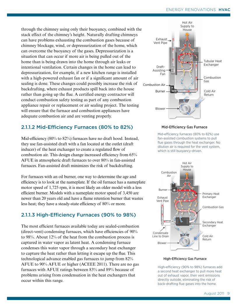
2.1.1.2 Mid-Efficiency Furnaces (80% to 82%)
Mid-efficiency (80% to 82%) furnaces have no draft hood. Instead, they use fan-assisted draft with a fan located at the outlet (draft inducer) of the heat exchanger to create a regulated flow of combustion air. This design change increased efficiency from 65% AFUE in atmospheric draft furnaces to over 80% in fan-assisted furnaces. Fan-assisted draft minimizes the risk of backdrafting.
For furnaces with an oil burner, one way to determine the age and efficiency is to look at the nameplate. If the oil furnace has a nameplate motor speed of 1,725 rpm, it is most likely an older model with a less efficient burner. Models with a nameplate motor speed of 3,450 are newer than 20 years old and have a flame retention burner that wastes less heat; they have a steady-state efficiency of 80% or more.
2.1.1.3 High-Efficiency Furnaces (90% to 98%)
The most efficient furnaces available today are sealed-combustion (direct-vent) condensing furnaces, which have efficiencies of 90% to 98%. About 12% of the heat from the combustion process is captured in water vapor as latent heat. A condensing furnace condenses this water vapor through a secondary heat exchanger to capture the heat rather than letting it escape up the flue. This technological advance enabled gas furnaces to jump from 82% AFUE to 90% AFUE or higher (ACEEE 2011). There are no gas furnaces with AFUE ratings between 83% and 89% because of problems arising from condensation in the heat exchangers that occur within this range.
Mid-efficiency furnaces (80% to 82%) use fan-assisted combustion systems to pull flue gases through the heat exchanger. No dilution air is required for the vent system, which is still buoyancy-driven.
High-efficiency (90% to 98%) furnaces add a second heat exchanger to pull more heat out of exhaust vapor, then vent emissions directly outside, eliminating the risk of back-drafting flue gases into the home.
August 2011 9
9
ENERGY RENOVATIONS HVAC
High-efficiency condensing furnaces avoid back-drafting issues by having sealed combustion. These furnaces are designed to vent exhaust gases (combustion products) directly to the outside through a dedicated vent pipe. They should also be installed with a second vent pipe to bring outside air directly into the combustion chamber.
Although a condensing unit costs more than a non-condensing unit, the condensing unit will save money in fuel costs over its 15- to 20-year life and is a particularly wise investment in cold climates.
Both mid- and high–efficiency furnaces are available with two-stage gas valves, two-speed draft fans, and variable-speed blower fans, which reduce their electricity usage by better matching air flow rate to the heating needs of the home.
Nearly all combustion furnaces sold today meet or exceed 80% AFUE. About one-third of current sales on a national basis are 90% AFUE or better. In just the past 10 years alone, about 7.5 million condensing furnaces went into replacement installations in the United States (ACEEE 2011).
The AFUE rating for an all-electric resistance furnace or boiler is between 95% and 100%; because there is no combustion, no heat loss occurs up the flue, but there may be some heat loss through the furnace housing. However in some parts of the country, electricity is expensive to purchase and it can be expensive to produce from an environmental standpoint as well, making electric heat a less cost-effective option.
2.1.2 Repair or Replace?
Although older combustion furnaces have efficiencies in the range of 56% to 70%, modern conventional heating systems can achieve efficiencies as high as 98%, converting nearly all the fuel to useful heat for your home. Energy-efficiency upgrades like sealing ducts and air leaks and adding insulation, together with a new high-efficiency heating system, can often cut your fuel bills and your furnace’s pollution output in half. Upgrading your furnace or boiler from 60% to 90% efficiency in an average cold-climate house will save 1.5 tons of carbon dioxide emissions each year if you heat with gas, or 2.5 tons of emissions if you heat with oil (ENERGY STAR calculator, www.energystar.gov).
A contractor can help you determine whether your furnace or boiler is too old, worn out, inefficient, or oversized. If it is, the simplest solution is to replace it with a modern high-efficiency model. A newer furnace may be more efficient but is still likely to be oversized.
Bigger isn’t Always Better
Many older furnaces and central air conditioning systems are oversized. An energy performance contractor can run energy analysis software to help you determine your heating and cooling needs after air sealing and insulation improvements are made.
In the past, many HVAC contractors used “rules of thumb” to determine HVAC sizing and, as a result, many installed oversized systems. Today's trained HVAC contractor should determine your heating and cooling loads, and the right size for your HVAC equipment, based on calculations developed by the Air Conditioning Contractors of America (ACCA 2005; 1995; 2009).
The ACCA published its guidelines in Manuals J, S, and D. Manual J outlines the procedures necessary to estimate the heat loss and heat gain of residential structures. Manual S provides guidance for equipment selection based on load calculations. Manual D describes proper duct sizing and design.
It should be noted that, in a cold climate, if the homeowner chooses to install an air-source central heat pump for heating and cooling, the contractor may opt for a larger size heat pump than indicated by Manual S to minimize the need for back up heat. This is a tradeoff—as the heat pump may then be oversized for the cooling load. Also, with the variable-speed motors and variable refrigerant flow compressors now available in some of the newest models of furnaces and heat pumps, oversizing is less of an issue because the equipment can modulate to operate at lower, more energy-efficient speeds when the demand is lower.
10 August 2011
ENERGY RENOVATIONS HVAC
If you plan to make energy-efficiency improvements to your home at the same time that you replace your furnace, talk to your contractor about how they will affect your furnace system. With a better building envelope, the new furnace or boiler can sometimes be a smaller size than the original, which can save you money. Whenever you make energy efficiency upgrades, your contractor should test to make sure that any new and existing combustion appliances (such as a furnace, water heater, or clothes dryer) still operate safely.
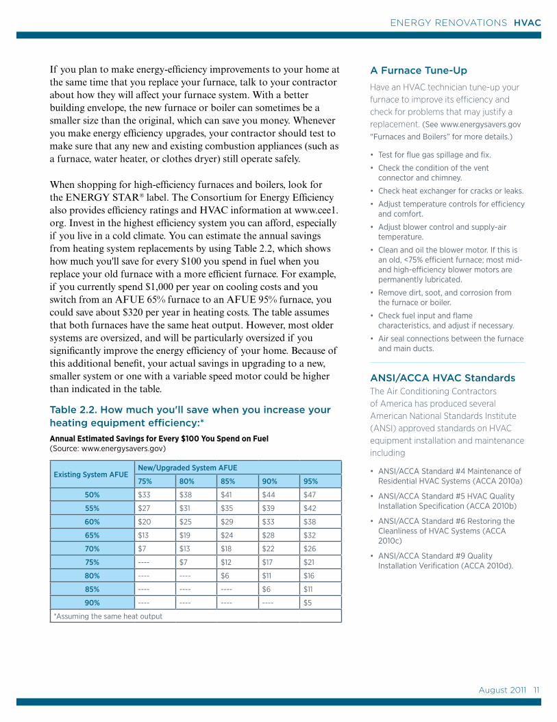
When shopping for high-efficiency furnaces and boilers, look for the ENERGY STAR® label. The Consortium for Energy Efficiency also provides efficiency ratings and HVAC information at www.cee1.org. Invest in the highest efficiency system you can afford, especially if you live in a cold climate. You can estimate the annual savings from heating system replacements by using Table 2.2, which shows how much you'll save for every $100 you spend in fuel when you replace your old furnace with a more efficient furnace. For example, if you currently spend $1,000 per year on cooling costs and you switch from an AFUE 65% furnace to an AFUE 95% furnace, you could save about $320 per year in heating costs. The table assumes that both furnaces have the same heat output. However, most older systems are oversized, and will be particularly oversized if you significantly improve the energy efficiency of your home. Because of this additional benefit, your actual savings in upgrading to a new, smaller system or one with a variable speed motor could be higher than indicated in the table.
Table 2.2. How much you'll save when you increase your heating equipment efficiency:* Annual Estimated Savings for Every $100 You Spend on Fuel (Source: www.energysavers.gov)
Existing System AFUENew/Upgraded System AFUE
75% 80% 85% 90% 95%
50% $33 $38 $41 $44 $47
55% $27 $31 $35 $39 $42
60% $20 $25 $29 $33 $38
65% $13 $19 $24 $28 $32
70% $7 $13 $18 $22 $26
75% ---- $7 $12 $17 $21
80% ---- ---- $6 $11 $16
85% ---- ---- ---- $6 $11
90% ---- ---- ---- ---- $5
*Assuming the same heat output
A Furnace Tune-Up
Have an HVAC technician tune-up your furnace to improve its efficiency and check for problems that may justify a replacement. (See www.energysavers.gov “Furnaces and Boilers” for more details.)
• Test for flue gas spillage and fix.
• Check the condition of the vent connector and chimney.
• Check heat exchanger for cracks or leaks.
• Adjust temperature controls for efficiency and comfort.
• Adjust blower control and supply-air temperature.
• Clean and oil the blower motor. If this is an old, <75% efficient furnace; most mid- and high-efficiency blower motors are permanently lubricated.
• Remove dirt, soot, and corrosion from the furnace or boiler.
• Check fuel input and flame characteristics, and adjust if necessary.
• Air seal connections between the furnace and main ducts.
ANSI/ACCA HVAC StandardsThe Air Conditioning Contractors of America has produced several American National Standards Institute (ANSI) approved standards on HVAC equipment installation and maintenance including
• ANSI/ACCA Standard #4 Maintenance of Residential HVAC Systems (ACCA 2010a)
• ANSI/ACCA Standard #5 HVAC Quality Installation Specification (ACCA 2010b)
• ANSI/ACCA Standard #6 Restoring the Cleanliness of HVAC Systems (ACCA 2010c)
• ANSI/ACCA Standard #9 Quality Installation Verification (ACCA 2010d).
August 2011 11
11
ENERGY RENOVATIONS HVAC
If your furnace is less than 15 to 20 years old and you decide to keep it, talk to your contractor about options for improving its efficiency. Repairing the furnace and its distribution system to increase efficiency may be an option. The costs of repairs should be weighed against the cost of a new furnace, taking into consideration the age and condition of the system. If the cost of repairs is more than half the cost of replacement, it is better to replace with a new system than to invest in repairing an old one (Krigger and Dorsi 2009). See the Furnace Tune-Up checklist (in sidebar) for maintenance activities that an HVAC technician can perform to improve your existing system’s efficiency.
One way to improve furnace efficiency may be to replace a single-speed blower fan motor with an electrically commutated (ECM) variable-speed fan motor. Your HVAC contractor should take into account the size and condition of your current ducts when considering this option to determine if any energy savings can be gained. (If the ducts are poorly installed or in bad condition, an ECM motor will work harder to push air through, negating any energy savings compared to a standard split-capacitor fan motor.)Other ways to improve HVAC energy efficiency include installing programmable thermostats, and pressure testing, air sealing, and insulating ducts. For more suggestions on improving furnace efficiency, see www.energysavers.gov, “Furnaces and Boilers.” See Section 2.1.3 of this guide for more information on ways to save energy with duct design, installation, and air sealing.
2.1.3 Ducts
Heated air from the furnace is distributed throughout your home via ducts located in the attic, basement, crawlspace, in ceiling soffits, or between floors. Supply ducts supply conditioned air from the furnace to the rooms of your house. Return air is air that comes from the rooms back to the furnace for filtering and reconditioning, either through individual ducted returns in each room or through a return register located in a central place like a hallway ceiling. The age and condition of these ducts is a factor in deciding whether to keep or replace a heating system. For example, the cost of replacing a poorly installed, leaky duct system may justify the switch to ductless heat pumps.
As part of a home performance assessment, the energy contractor will inspect your ducts for proper installation and insulation and test them for duct air tightness and air flow at each register. Heating and cooling comfort complaints can often be addressed by fixing blocked registers, stuck dampers, or disconnected or damaged ducts, or by replacing register grilles that don't direct the air adequately.
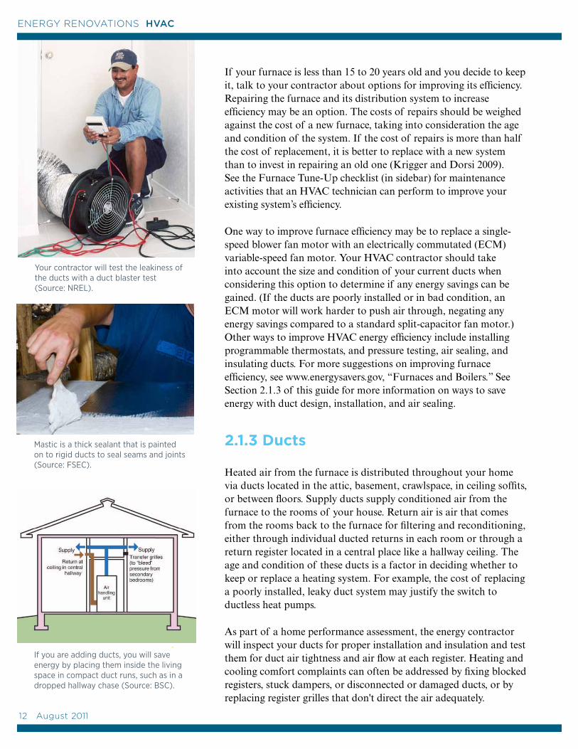
Your contractor will test the leakiness of the ducts with a duct blaster test (Source: NREL).
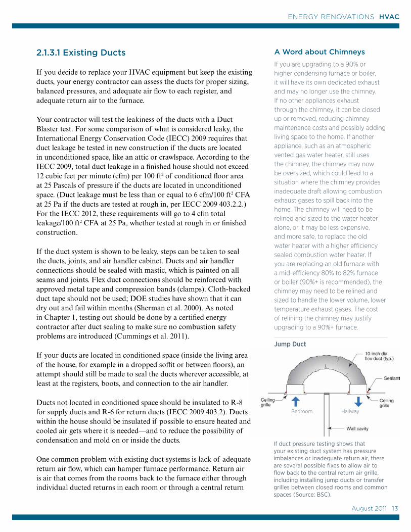
Mastic is a thick sealant that is painted on to rigid ducts to seal seams and joints (Source: FSEC).
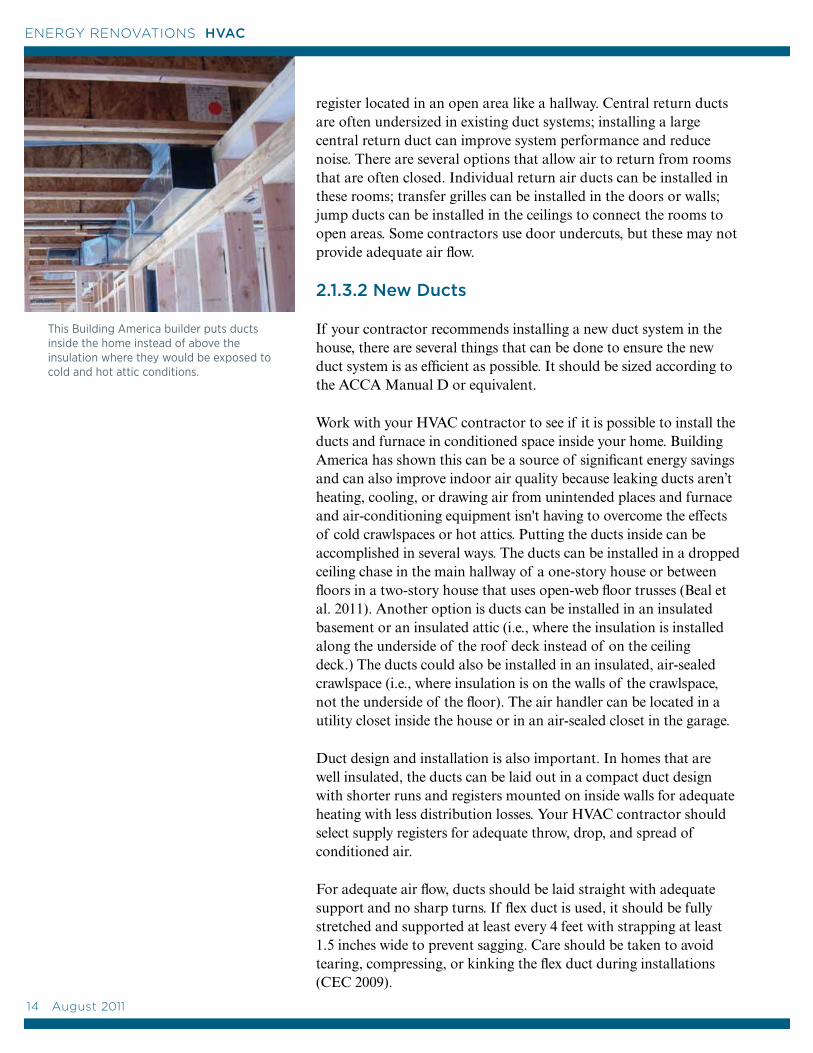
If you are adding ducts, you will save energy by placing them inside the living space in compact duct runs, such as in a dropped hallway chase (Source: BSC).
12 August 2011
ENERGY RENOVATIONS HVAC
A Word about Chimneys
If you are upgrading to a 90% or higher condensing furnace or boiler, it will have its own dedicated exhaust and may no longer use the chimney. If no other appliances exhaust through the chimney, it can be closed up or removed, reducing chimney maintenance costs and possibly adding living space to the home. If another appliance, such as an atmospheric vented gas water heater, still uses the chimney, the chimney may now be oversized, which could lead to a situation where the chimney provides inadequate draft allowing combustion exhaust gases to spill back into the home. The chimney will need to be relined and sized to the water heater alone, or it may be less expensive, and more safe, to replace the old water heater with a higher efficiency sealed combustion water heater. If you are replacing an old furnace with a mid-efficiency 80% to 82% furnace or boiler (90%+ is recommended), the chimney may need to be relined and sized to handle the lower volume, lower temperature exhaust gases. The cost of relining the chimney may justify upgrading to a 90%+ furnace.
2.1.3.1 Existing Ducts
If you decide to replace your HVAC equipment but keep the existing ducts, your energy contractor can assess the ducts for proper sizing, balanced pressures, and adequate air flow to each register, and adequate return air to the furnace.
Your contractor will test the leakiness of the ducts with a Duct Blaster test. For some comparison of what is considered leaky, the International Energy Conservation Code (IECC) 2009 requires that duct leakage be tested in new construction if the ducts are located in unconditioned space, like an attic or crawlspace. According to the IECC 2009, total duct leakage in a finished house should not exceed 12 cubic feet per minute (cfm) per 100 ft2 of conditioned floor area at 25 Pascals of pressure if the ducts are located in unconditioned space. (Duct leakage must be less than or equal to 6 cfm/100 ft2 CFA at 25 Pa if the ducts are tested at rough in, per IECC 2009 403.2.2.) For the IECC 2012, these requirements will go to 4 cfm total leakage/100 ft2 CFA at 25 Pa, whether tested at rough in or finished construction.
If the duct system is shown to be leaky, steps can be taken to seal the ducts, joints, and air handler cabinet. Ducts and air handler connections should be sealed with mastic, which is painted on all seams and joints. Flex duct connections should be reinforced with approved metal tape and compression bands (clamps). Cloth-backed duct tape should not be used; DOE studies have shown that it can dry out and fail within months (Sherman et al. 2000). As noted in Chapter 1, testing out should be done by a certified energy contractor after duct sealing to make sure no combustion safety problems are introduced (Cummings et al. 2011).
If your ducts are located in conditioned space (inside the living area of the house, for example in a dropped soffit or between floors), an attempt should still be made to seal the ducts wherever accessible, at least at the registers, boots, and connection to the air handler.
Ducts not located in conditioned space should be insulated to R-8 for supply ducts and R-6 for return ducts (IECC 2009 403.2). Ducts within the house should be insulated if possible to ensure heated and cooled air gets where it is needed—and to reduce the possibility of condensation and mold on or inside the ducts.
One common problem with existing duct systems is lack of adequate return air flow, which can hamper furnace performance. Return air is air that comes from the rooms back to the furnace either through individual ducted returns in each room or through a central return
If duct pressure testing shows that your existing duct system has pressure imbalances or inadequate return air, there are several possible fixes to allow air to flow back to the central return air grille, including installing jump ducts or transfer grilles between closed rooms and common spaces (Source: BSC).
Bedroom Hallway
Jump Duct
August 2011 13
13
ENERGY RENOVATIONS HVAC
register located in an open area like a hallway. Central return ducts are often undersized in existing duct systems; installing a large central return duct can improve system performance and reduce noise. There are several options that allow air to return from rooms that are often closed. Individual return air ducts can be installed in these rooms; transfer grilles can be installed in the doors or walls; jump ducts can be installed in the ceilings to connect the rooms to open areas. Some contractors use door undercuts, but these may not provide adequate air flow.
2.1.3.2 New Ducts
If your contractor recommends installing a new duct system in the house, there are several things that can be done to ensure the new duct system is as efficient as possible. It should be sized according to the ACCA Manual D or equivalent.
Work with your HVAC contractor to see if it is possible to install the ducts and furnace in conditioned space inside your home. Building America has shown this can be a source of significant energy savings and can also improve indoor air quality because leaking ducts aren’t heating, cooling, or drawing air from unintended places and furnace and air-conditioning equipment isn't having to overcome the effects of cold crawlspaces or hot attics. Putting the ducts inside can be accomplished in several ways. The ducts can be installed in a dropped ceiling chase in the main hallway of a one-story house or between floors in a two-story house that uses open-web floor trusses (Beal et al. 2011). Another option is ducts can be installed in an insulated basement or an insulated attic (i.e., where the insulation is installed along the underside of the roof deck instead of on the ceiling deck.) The ducts could also be installed in an insulated, air-sealed crawlspace (i.e., where insulation is on the walls of the crawlspace, not the underside of the floor). The air handler can be located in a utility closet inside the house or in an air-sealed closet in the garage.
Duct design and installation is also important. In homes that are well insulated, the ducts can be laid out in a compact duct design with shorter runs and registers mounted on inside walls for adequate heating with less distribution losses. Your HVAC contractor should select supply registers for adequate throw, drop, and spread of conditioned air.
For adequate air flow, ducts should be laid straight with adequate support and no sharp turns. If flex duct is used, it should be fully stretched and supported at least every 4 feet with strapping at least 1.5 inches wide to prevent sagging. Care should be taken to avoid tearing, compressing, or kinking the flex duct during installations (CEC 2009).
This Building America builder puts ducts inside the home instead of above the insulation where they would be exposed to cold and hot attic conditions.
14 August 2011
ENERGY RENOVATIONS HVAC
2.2 Electric Heaters
Currently, 14% of U.S. single-family homes use electric resistance heat to heat their homes: almost 11% have an electric central forced-air furnace, and more than 3% use some form of electric space heating. An additional 10% use heat pumps, which will be described in the next section.
2.2.1 Electric Central Furnaces
Electric forced-air furnaces distribute heat with an air handler and ducts, just like gas furnaces (see Section 2.1 for more on furnaces and ducts). The AFUE rating for an all-electric furnace is 95% to 100%. This is because electric furnaces provide heat through resistance, not combustion, so there are no heat losses up the chimney. All of the electricity is converted to heat, minus a small amount of heat loss through the air handler cabinet. This AFUE rating does not include any heat losses through leaky or uninsulated ducts. However, although it varies based on local utility rates, electricity is still one of the most expensive heating fuels.
If you have an electric furnace and your duct system is good, consider switching to a high-performance air-source heat pump. Electricity savings can be 30% or more when compared with electric resistance heating.
2.2.2 Room Heaters
Room heating here refers to heating systems that heat one room or area of a home, unlike central systems, which distribute heat throughout the entire house via ducts or piping. Electricity is the most common fuel type for room heaters, but there are other fuel types as well.
Unvented combustion space heaters, which can release dangerous combustion gases into the home, are illegal in some states and should not be used. The use of portable space heaters is also not recommended because of their inefficiency and potential burn and tripping hazards.
In an average- or large-sized home with minimal or average insulation, electric resistance room heaters (baseboard or wall-mounted) are not typically a cost-effective method for heating the whole house over the long term. In a very well-insulated and air sealed home that requires little heating, they can be a cost-effective choice. They can also be a cost-effective choice for heating infrequently used rooms when the main living areas are heated with ductless heat pumps or radiant floor heat.
Building America's Consortium for Advanced Residential Buildings (CARB) worked with Rural Development, Inc. to design a community of townhouses in western Massachusetts that were so well insulated that a two-stage sealed-combustion gas space heater met the design load. The heaters had a capacity of 10,200 Btu/hr on low fire and 16,000 Btu/hr on high fire with an AFUE of 83% (Source: Rural Development, Inc.).
Although not cost-effective as your main heating source, in a home with average insulation, baseboard electric heaters are an inexpensive way to provide supplemental room heating.
August 2011 15
15
ENERGY RENOVATIONS HVAC
2.2.3 Zoning
Many homeowners who have forced-air systems will shut vents and close a door in a room they aren’t using, thinking that this saves energy. This is not recommended because it can reduce airflow through the air handler, causing pressure imbalances, putting stress on the duct connections, and affecting air quality if you are using your air handler for ventilation. Zoning can be accomplished with central forced-air systems, using damper controls installed in the ducts by an HVAC professional, but the dampers will affect system efficiency and balance. In large homes, zoning of central heating and forced-air systems is more commonly (and more effectively) accomplished by installing multiple systems, with one unit per floor.
Hydronic heating systems can be configured, with piping and valves, to provide zone heating. Zone control works best in homes where the different zones can be isolated from each other with closable doors. Never shut off the heat entirely in an unused part of your home because condensation could form on cold inside wall surfaces leading to mold. Keep all rooms at a minimum of 50°F in the winter to prevent water pipes from freezing.
Room heaters can be used as an inexpensive way to provide zone heating when a central forced-air system is the main heating system for the home. Other forms of room heating that might be considered for supplemental heating or for additions include ductless heat pumps (described in Section 2.3.2), electric radiant wall and ceiling panels, active solar space heating (described in Section 2.6), sealed-combustion gas room heaters, and high-efficiency wood or pellet stoves (see Section 2.5).
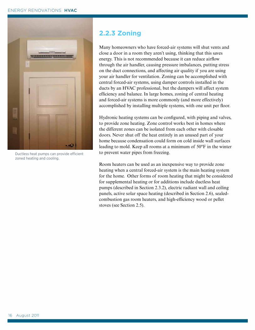
Ductless heat pumps can provide efficient zoned heating and cooling.
16 August 2011
ENERGY RENOVATIONS HVAC
Outdoor CoilsEvaporator
Compressor
Expansion Valve
Indoor Coils Condenser
Gas condenses into a liquid, releasing heat inside
Gas condenses into a liquid
releasing heat to the outside
Compressor
Liquid evaporatesinto gas pulling heat from the inside
Fan
Liquid evaporates
into gas,pulling heat from outside
Indoor CoilsEvaporator
Expansion Valve
Outdoor CoilsCondenser
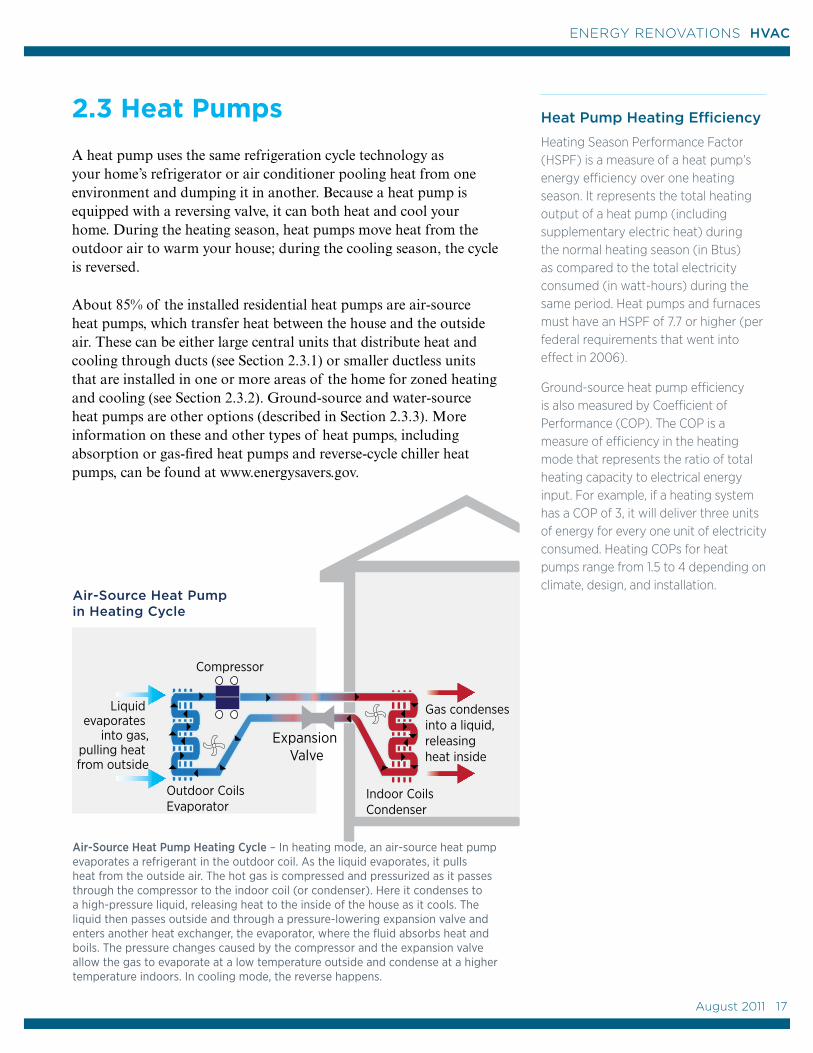
Air-Source Heat Pump Heating Cycle – In heating mode, an air-source heat pump evaporates a refrigerant in the outdoor coil. As the liquid evaporates, it pulls heat from the outside air. The hot gas is compressed and pressurized as it passes through the compressor to the indoor coil (or condenser). Here it condenses to a high-pressure liquid, releasing heat to the inside of the house as it cools. The liquid then passes outside and through a pressure-lowering expansion valve and enters another heat exchanger, the evaporator, where the fluid absorbs heat and boils. The pressure changes caused by the compressor and the expansion valve allow the gas to evaporate at a low temperature outside and condense at a higher temperature indoors. In cooling mode, the reverse happens.
Air-Source Heat Pump in Heating Cycle
Heat Pump Heating Efficiency
Heating Season Performance Factor (HSPF) is a measure of a heat pump’s energy efficiency over one heating season. It represents the total heating output of a heat pump (including supplementary electric heat) during the normal heating season (in Btus) as compared to the total electricity consumed (in watt-hours) during the same period. Heat pumps and furnaces must have an HSPF of 7.7 or higher (per federal requirements that went into effect in 2006).
Ground-source heat pump efficiency is also measured by Coefficient of Performance (COP). The COP is a measure of efficiency in the heating mode that represents the ratio of total heating capacity to electrical energy input. For example, if a heating system has a COP of 3, it will deliver three units of energy for every one unit of electricity consumed. Heating COPs for heat pumps range from 1.5 to 4 depending on climate, design, and installation.
2.3 Heat Pumps
A heat pump uses the same refrigeration cycle technology as your home’s refrigerator or air conditioner pooling heat from one environment and dumping it in another. Because a heat pump is equipped with a reversing valve, it can both heat and cool your home. During the heating season, heat pumps move heat from the outdoor air to warm your house; during the cooling season, the cycle is reversed.
About 85% of the installed residential heat pumps are air-source heat pumps, which transfer heat between the house and the outside air. These can be either large central units that distribute heat and cooling through ducts (see Section 2.3.1) or smaller ductless units that are installed in one or more areas of the home for zoned heating and cooling (see Section 2.3.2). Ground-source and water-source heat pumps are other options (described in Section 2.3.3). More information on these and other types of heat pumps, including absorption or gas-fired heat pumps and reverse-cycle chiller heat pumps, can be found at www.energysavers.gov.
August 2011 17
17
ENERGY RENOVATIONS HVAC
2.3.1 Central Air-Source Heat Pumps
Most heat pumps installed in U.S. homes are central air-source heat pumps that distribute heated and cooled air through ducts, just like a central forced-air furnace. Most of these air-source heat pumps are split systems meaning that the air handler (which houses the blower fan) is indoors and the compressor is outdoors. The air handler contains the blower and the inside coil for the heat pump.
Current federal law requires that air-source heat pumps have a minimum heating efficiency, or Heating Season Performance Factor (HSPF), of 7.7 and a minimum cooling efficiency of Seasonal Energy Efficiency Ratio (SEER) of 13. Higher efficiency central air-source heat pump models are available with up to 9.6 HSPF and SEER 23.
Because the heating efficiency of standard, central air-source heat pumps drops when outside temperatures drop below about 35°F, a backup heat source is often needed, especially in cold climates. Air-source heat pumps can be all-electric or dual-fuel systems. All-electric air-source heat pumps come equipped with electric-resistance strip heaters for supplementary heat if needed. Dual-fuel systems combine the air-source heat pump with another source of supplementary heat, such as a gas furnace. Another type of central air-source heat pump developed in Canada for cold climates is the bivalent heat pump; it uses a gas- or propane-fired burner to increase the temperature of the air entering the outdoor coil, allowing the unit to operate at lower outdoor temperatures with less frost buildup on the outside coil (NRCan 2009).
If you heat with electricity, a heat pump can trim the amount of electricity used for heating by as much as 30% to 40% compared to electric resistance heat. The efficiency of today's air-source heat pumps is one to two times greater than those available 30 years ago due to technical advances such as thermostatic expansion valves, variable-speed blowers, improved coil design, two-speed compressors (instead of single-speed compressors), and improved motor designs (www.energysavers.gov). Variable-speed compressor designs that better match refrigerant flow to load are in development and will make heat pumps more effective at lower outside temperatures. Variable-refrigerant-flow, ductless “mini-split” heat pumps are already available that can heat at 100% capacity at outdoor temperatures as low as 5°F.
If you plan to install a heat pump, ask your HVAC installer to confirm that the existing ducts are appropriately sized for the heat pump. Ducts may need to be larger for a heat pump than for a gas
A Central Air-Source Heat Pump Checklist
Here is a checklist of maintenance activities that you or your HVAC contractor can do to maintain your heat pump’s efficiency and performance. (See www.energysavers.gov “Air-Source Heat Pumps” for more details.)
• Inspect and clean filters monthly or per manufacturers’ instructions.
• Vacuum or brush coils.
• Clean the fan; oil the fan motor only if the manufacturer instructions specify this, newer models are sealed.
• Check the fan for incorrect pulley settings, loose fan belts, or incorrect motor speeds.
• Inspect ductwork; make sure air flow is not restricted by loose insulation, abnormal buildup of dust, or any other obstacles that occasionally find their way through the grills.
• Be sure that vents and registers are not blocked by furniture, carpets, or other items that can stop airflow.
• Confirm that the drain pan is draining correctly.
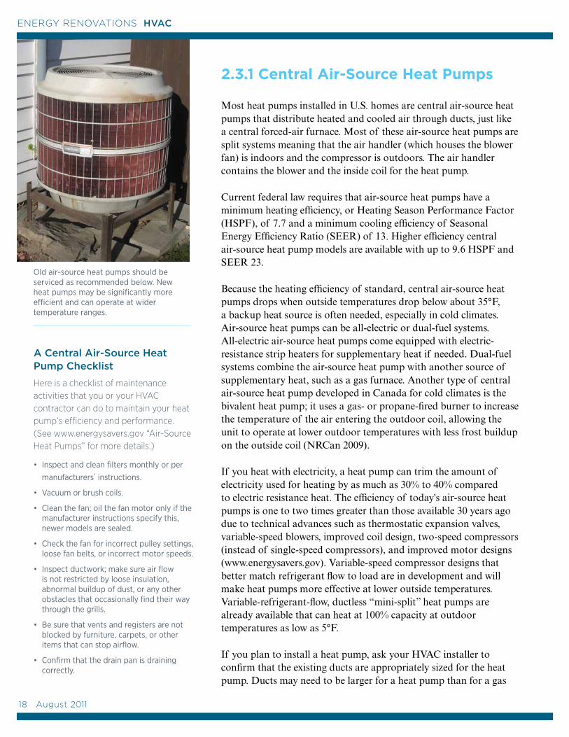
Old air-source heat pumps should be serviced as recommended below. New heat pumps may be significantly more efficient and can operate at wider temperature ranges.
18 August 2011
ENERGY RENOVATIONS HVAC
or oil furnace because furnaces generally deliver air to the living space at between 130°F and 140°F. Heat pumps provide air at about 80°F to 115°F so more air needs to be delivered to provide the same amount of warmth (NRCan 2009). Your HVAC contractor should confirm that the supply air registers achieve a “throw” appropriate for a heat pump. Choosing the right register design can be important for minimizing comfort complaints because heat pumps blow more air at cooler temperatures than gas- or oil-fired furnaces.
Some researchers suggest central-air-source heat pumps may need to be slightly oversized, to enable the system to provide enough warmth without turning on the backup heat.
2.3.2 Ductless Heat Pumps
High-performance ductless heat pumps are an efficient alternative to central ducted heat pump systems. Ductless heat pumps are sometimes referred to as mini-split heat pumps because they consist of a single outside compressor/condenser unit connected to one or more wall- or ceiling-mounted indoor air handler units. They can provide zone heating and cooling without ducts. The outdoor units are mounted on the wall or on a concrete or stone pad outside the house; refrigerant tubing connects the inside and outside units through a small hole in the wall.
Ductless heat pumps have been used in Asia and Europe since the 1970s and they comprise 80% to 90% of the residential HVAC market there. They have been used in U.S. commercial buildings since the 1980s, but they still comprise less than 3% of the U.S. residential market (Karr 2011). They are 25% to 50% more efficient than electric baseboard or wall heaters (NEEA 2009). Ductless heat pumps provide increased energy savings over standard heat pumps in several ways. Because they are ductless and mounted inside conditioned space, they avoid the distribution losses of a central furnace that has leaky ducts installed in an unheated attic or crawlspace. Ductless heat pumps provide zoned heating because units can be turned off or not installed in rooms that aren’t being used. They use a much smaller blower than central units; however, more than one inside unit is typically needed to serve the whole house. Up to eight inside units can be connected to one outside unit.
Advances in technology in recent years have increased performance to the point that units are now available with heating efficiencies as high as 12 HSPF and cooling efficiencies as high as SEER 26. The most efficient ductless heat pumps use a variable-speed compressor that can vary the refrigerant flow. They also have linear expansion
Ductless Demo Hits 10,000
The Northwest Ductless Heat Pump Project is a large-scale ductless heat pump demonstration project conducted by the Bonneville Power Administration and the Northwest Energy Efficiency Alliance that has installed more than 10,000 ductless heat pumps since 2009. See their site (www.nwductless.com) for more information on ductless heat pumps, including installation tips, product recommendations, and performance details.
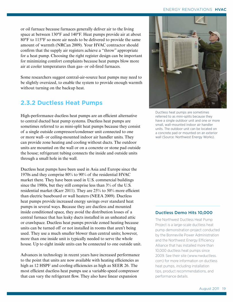
Ductless heat pumps are sometimes referred to as mini-splits because they have a single outdoor unit and one or more small, wall-mounted indoor air handler units. The outdoor unit can be located on a concrete pad or mounted on an exterior wall (Source: Northwest Energy Works).
August 2011 19
19
ENERGY RENOVATIONS HVAC
Ground,Looped
Collector
Ground,Horizontal Collector
Ground,Vertical
Collector
Pond, Looped
Collector
GroundSource
Heat Pump
valves rather than open/close valves, and multi-speed rather than single-speed fans to continuously match the heating or cooling load. Unlike conventional air-conditioning and heating systems that stop and start repetitively, the inverter technology adjusts the motor speed, allowing the system to adapt more smoothly to shifts in demand with less temperature variation and much lower energy use. When maximum capacity is not needed, compressor revolution and power decreases, increasing energy efficiency. For example, one model reports a capacity range of 3,100-24,000 Btus in heating mode and 3,800-14,500 Btus in cooling mode.
The best performing ductless heat pump models perform at a much wider temperature range than standard heat pumps. Some models can operate at an outdoor temperature range of -5°F to 75°F for heating and 14°F to 115°F for cooling, eliminating the need for backup heat sources in most locations.
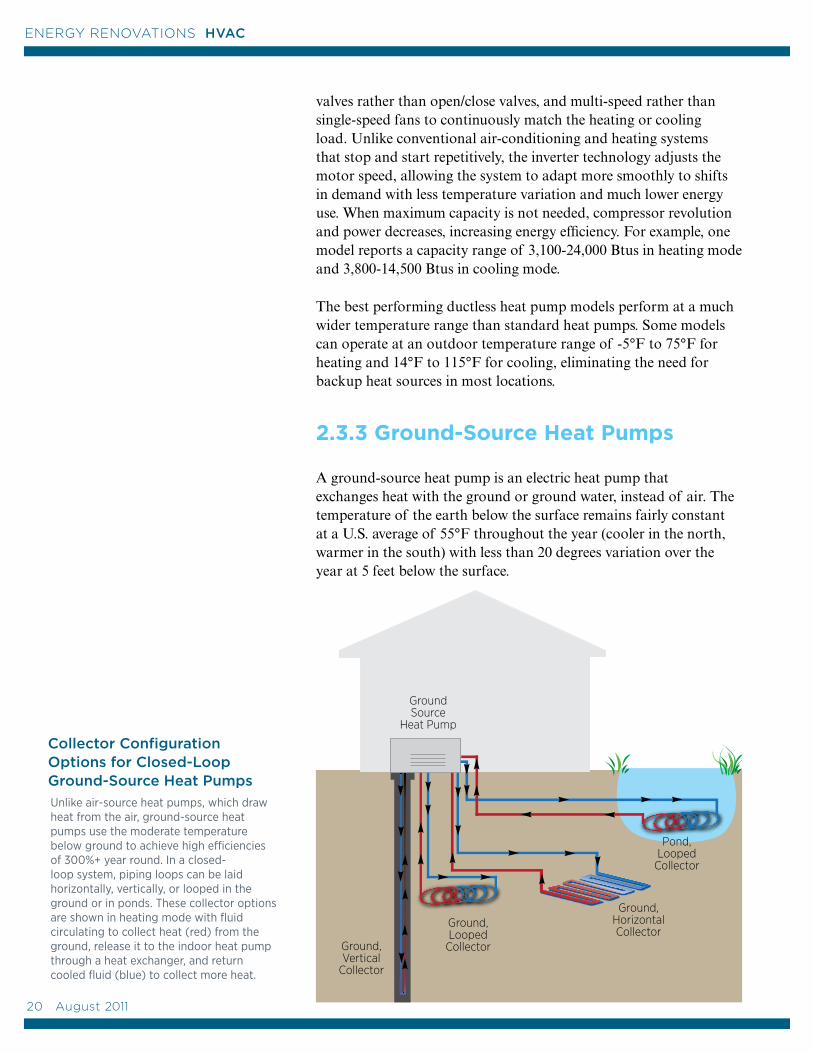
2.3.3 Ground-Source Heat Pumps
A ground-source heat pump is an electric heat pump that exchanges heat with the ground or ground water, instead of air. The temperature of the earth below the surface remains fairly constant at a U.S. average of 55°F throughout the year (cooler in the north, warmer in the south) with less than 20 degrees variation over the year at 5 feet below the surface.
Unlike air-source heat pumps, which draw heat from the air, ground-source heat pumps use the moderate temperature below ground to achieve high efficiencies of 300%+ year round. In a closed-loop system, piping loops can be laid horizontally, vertically, or looped in the ground or in ponds. These collector options are shown in heating mode with fluid circulating to collect heat (red) from the ground, release it to the indoor heat pump through a heat exchanger, and return cooled fluid (blue) to collect more heat.
Collector Configuration Options for Closed-Loop Ground-Source Heat Pumps
20 August 2011
ENERGY RENOVATIONS HVAC
Because heat is exchanged with the ground rather than the outside air, which has more erratic temperatures, ground-source heat pumps remain a very efficient source of heating and cooling all year. Additional efficiency is gained by using water rather than air as the heat-exchange fluid (Karr 2011). (The ground-source systems we are describing here do not include the geothermal systems that use high below-ground temperatures associated with volcanic activity for heat and power production.)
Ground-source heat pumps may be closed-loop or open-loop systems. A “closed-loop” ground-source heat pump circulates water (or a mixture of water and anti-freeze) from the heat pumps to horizontal or vertical pipes that are buried in the ground in contact with the earth, which serves as a heat source in winter and heat sink in summer. After exchanging heat with the ground, the water is circulated back to the heat pumps in a closed loop. Closed-loop configurations include piping laid in horizontal rows or loops in trenches 5 to 10 feet deep, or vertical loops inserted in boreholes that are 75 to 500 feet deep and filled in with bentonite or other grout materials to aid heat transfer to the soil. Closed loops can also be laid in a private pond to exchange heat with the pond water. Another much less common type of closed-loop system is the direct exchange heat pump, which circulates refrigerant rather than water or antifreeze directly through the ground in a single closed loop of copper tubing. This system uses more refrigerant and copper tubing, which are expensive but are more efficient at heat transfer so less tubing length and thus less digging is required.
An “open-loop” ground-source heat pump uses groundwater from a well as the heat source and heat sink. The water circulates through the heat pump(s) once and is returned to the ground through a separate injection well or through surface discharge (EIA 2010).
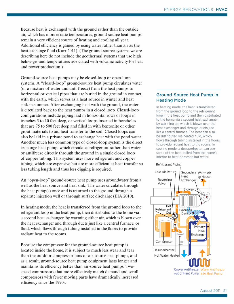
In heating mode, the heat is transferred from the ground loop to the refrigerant loop in the heat pump, then distributed to the home via a second heat exchanger, by warming either air, which is blown over the heat exchanger and through ducts just like a central furnace, or fluid, which flows through tubing installed in the floors to provide radiant heat to the rooms.
Because the compressor for the ground-source heat pump is located inside the home, it is subject to much less wear and tear than the outdoor compressor fans of air-source heat pumps, and as a result, ground-source heat pump equipment lasts longer and maintains its efficiency better than air-source heat pumps. Two-speed compressors that more effectively match demand and scroll compressors with fewer moving parts have dramatically increased efficiency since the 1990s.
Warm Air to House
Blower
Secondary Heat Exchanger
Warm Antifreeze into Heat Pump
Cooler Antifreeze out of Heat Pump
Hot Water Heater
Desuperheater
HotRefrigerant
Out
Cold Air Return
Refrigerant Piping
Compressor
Reversing Valve
Primary Heat
Exchanger
Expansion Device
Ground-Source Heat Pump in Heating Mode
In heating mode, the heat is transferred from the ground loop to the refrigerant loop in the heat pump and then distributed to the home via a second heat exchanger, by warming air, which is blown over the heat exchanger and through ducts just like a central furnace. The heat can also be distributed via heated fluid, which flows through tubing installed in the floors to provide radiant heat to the rooms. In cooling mode, a desuperheater can use some of the heat pulled from the home's interior to heat domestic hot water.
August 2011 21
21
ENERGY RENOVATIONS HVAC
Most ground-source heat pumps are equipped with a desuperheater, which is an auxiliary heat-recovery system that can be connected to the home’s water heater tank to provide up to 25% to 50% of the home’s domestic hot water (Smith and Arco 1996). Because they use extra heat from the cooling process they are more effective in hot climates where the heat pump is in cooling mode most of the time.
Ground-source heat pumps can have high installation costs because they require drilling or trenching (CEC 2011). If there is a pond on the property, the loops can be laid on the pond bed, a less costly installation than digging trenches, as long as the tubing is covered by 8 feet of water year-round.
Ground-source heat pumps have risen in popularity in the United States from 35,600 units shipped in 2000 to 115,400 ground-source heat pumps shipped in 2009. The ground-source closed-loop units shipped in 2009 had an averaged rated heating efficiency of 4.1 Energy Efficiency Ratio (EER) Btus/hr/W and an average rated cooling efficiency of 20.4 EER Btus/hr/W (EIA 2010).
Ground-source heat pump efficiencies of 300% to 600% have been reported, compared to 175% to 250% for central ducted air-source heat pumps (www.energysavers.gov). Pump power consumption is not usually included in the rated efficiency of the system and should be taken into account when considering a ground-source heat pump installation (Sherwin et al. 2010). Good thermal connectivity between the loop and ground is essential for high efficiency and soil irregularities can affect performance. System life is estimated at 25 years for the inside components and 50+ years for the ground loop (www.energysavers.gov).
While ground-source heat pumps can save more energy than central ducted air-source-heat pump systems, studies are still being done to determine whether their additional costs justify their installation over variable refrigerant flow ductless heat pumps. One option that has been proposed for increasing ground-source heat pump efficiency is combining the ground-source heat pump with the variable refrigerant flow technology of ductless heat pumps. In a modeling study of multifamily housing (using energy savings data that were confirmed by field studies), ground-source heat pumps combined with variable refrigerant flow technology cut energy use by 36% compared to an air-source central heat pump system, while ductless heat pumps cut energy use by 32% and a regular ground-source heat pump alone cut energy use by 28% (Karr 2011).
22 August 2011
ENERGY RENOVATIONS HVAC
2.4 Boilers and Hydronic Heating
Hydronic heating systems use steam or hot water that is heated by a boiler and distributed via pipes to radiators or baseboard convectors, or to tubes for radiant floor heating. The hot water can also be used to heat air via a coil and blower. The boiler may burn oil, gas, propane, or wood or use electricity to heat the water. The water may be preheated using a solar thermal system or ground-source heat pump. Steam is distributed via pipes to steam radiators. Hot water can be distributed via baseboard radiators, wall radiators, or radiant floor systems; or, the hot water can be used to heat air via a coil and blower. Steam boilers operate at a higher temperature than hot water boilers and are inherently less efficient, but high-efficiency versions of both types of boilers (up to 95%) are currently available.
The minimum federal rating for a fossil-fueled boiler is 80%. For more on boiler efficiency and considerations on replacing your existing boiler, see Section 2.1 above. Also see “Furnaces and Boilers” at www.energysavers.gov.
Hydronic heating systems can provide energy and cost savings by being zoned to only provide heating to areas of the house that are in use. Zoning can be done by installing separate circulating lines, using zone valves controlled by separate thermostats, or using a central electronic controller and emitters with controls on them.
2.4.1 Steam and Hot Water Radiators
Steam heating is one of the oldest heating technologies. Steam moves itself through piping without the use of pumps. Older, high-mass boilers are less efficient and there is also a significant lag time from when the boiler turns on to when the heat arrives in the radiators.
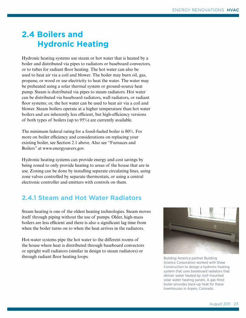
Hot-water systems pipe the hot water to the different rooms of the house where heat is distributed through baseboard convectors or upright wall radiators (similar in design to steam radiators) or through radiant floor heating loops. Building America partner Building
Science Corporation worked with Shaw Construction to design a hydronic heating system that uses baseboard radiators that deliver water heated by roof-mounted solar water heating panels. A gas-fired boiler provides back-up heat for these townhouses in Aspen, Colorado.
August 2011 23
23
ENERGY RENOVATIONS HVAC
2.4.2 Radiant Floor Heating
Hydronic radiant floor systems pump heated water through tubing, which is laid in a pattern underneath the floor. The cost of installing a hydronic radiant floor system varies by location and also depends on the size of the home, the type of installation, the floor covering, and the cost of labor. Because radiant floor heating requires lower temperature water than radiator heating, the water for hydronic floor heating can be heated or preheated with a solar thermal heating system or a ground-source heat pump.
When the heat source is a ground-source heat pump, the cycling can be reversed in the summer to provide cooling. Radiant floor cooling works best in dry climates; it is not recommended in humid climates because of the potential for condensation to form on the floor surface.
The tubing can be installed in traditional concrete slabs, a thin layer of concrete, or pre-grooved wood panels. The slab under the radiant tubing must be insulated. Some flooring types such as thick carpet can diminish the heat transfer ability of radiant flooring.
Radiant heat wall and ceiling panels that distribute hot water through tubing installed in wall- or ceiling-mounted panels are also available.
2.4.3 Repair or Replace
If you have an existing hydronic system that you are not ready to replace, talk to your contractor about what can be done to improve its efficiency. Hydronic systems can have problems with corrosion that clogs components. Some annual maintenance is required by homeowners and HVAC technicians. See the sidebar on this page for tune-up recommendations.
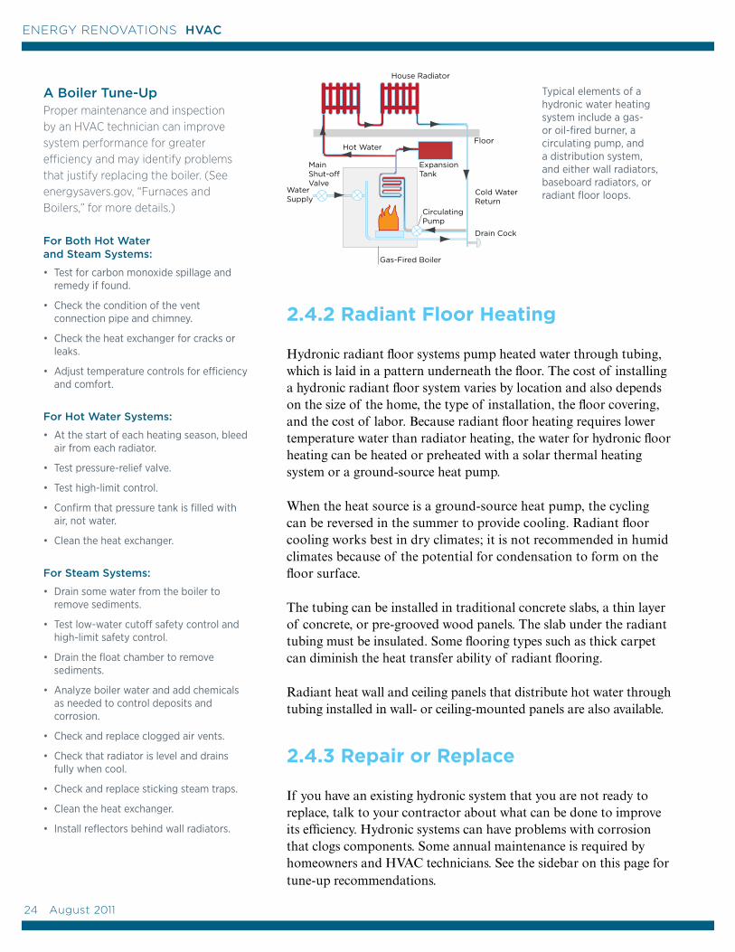
House Radiator
Hot WaterFloor
Expansion Tank
Gas-Fired Boiler
Circulating Pump
Cold WaterReturn
Drain Cock
WaterSupply
Main Shut-offValve
Typical elements of a hydronic water heating system include a gas- or oil-fired burner, a circulating pump, and a distribution system, and either wall radiators, baseboard radiators, or radiant floor loops.
A Boiler Tune-Up Proper maintenance and inspection by an HVAC technician can improve system performance for greater efficiency and may identify problems that justify replacing the boiler. (See energysavers.gov, “Furnaces and Boilers,” for more details.)
For Both Hot Water and Steam Systems:
• Test for carbon monoxide spillage and remedy if found.
• Check the condition of the vent connection pipe and chimney.
• Check the heat exchanger for cracks or leaks.
• Adjust temperature controls for efficiency and comfort.
For Hot Water Systems:
• At the start of each heating season, bleed air from each radiator.
• Test pressure-relief valve.
• Test high-limit control.
• Confirm that pressure tank is filled with air, not water.
• Clean the heat exchanger.
For Steam Systems:
• Drain some water from the boiler to remove sediments.
• Test low-water cutoff safety control and high-limit safety control.
• Drain the float chamber to remove sediments.
• Analyze boiler water and add chemicals as needed to control deposits and corrosion.
• Check and replace clogged air vents.
• Check that radiator is level and drains fully when cool.
• Check and replace sticking steam traps.
• Clean the heat exchanger.
• Install reflectors behind wall radiators.
24 August 2011
ENERGY RENOVATIONS HVAC

2.5 Wood and Pellet Heating
About 2.9 million households use wood as their primary heating source, and 8.9 million homes use it as a secondary heating source (EIA 2005). Newer wood- and pellet-burning appliances include models that are cleaner burning, more efficient, and powerful enough to heat many average-sized, modern homes.
Traditional open masonry fireplaces should not be considered heating devices. Traditional fireplaces draw in as much as 300 cubic feet per minute of heated room air for combustion, and then send it straight up the chimney. Fireplaces also produce significant air pollution. When burning a fire in a traditional fireplace, you should turn your heat down or off and open a window near the fireplace. Close the flue when the fireplace is not in use. Consider installing an inflatable flue stopper in rarely used fireplaces or during summer months to stop air leaks.
Pellet stoves, which burn small pellets made from compacted sawdust, wood chips, bark, recycled paper, or agricultural crop waste, are among the cleanest wood-burning options. They have combustion efficiencies of 78%–85%, heating capacities of 8,000 to 90,000 Btu per hour. They can be direct-vented to the outside and do not need a chimney. They require electricity to run the fans, controls, and pellet feeders.
Masonry heaters, also known as “Russian,” “Siberian,” and “Finnish” fireplaces, produce more heat and less pollution than any other wood- or pellet-burning appliance. They commonly reach a combustion efficiency of 90%. Masonry heaters include a firebox, a large masonry mass (such as bricks), and long twisting smoke channels that run through the masonry mass. A small hot fire built once or twice a day releases heated gases into the long masonry heat tunnels. The masonry absorbs the heat and then slowly releases it into the house over a period of 12–20 hours.
New high-efficiency wood stoves with catalytic combustors have advertised efficiencies of 70%–80%.
Modern fireplaces (which have vents under the firebox for drawing in room air, a heat exchanger, vents at the top of the fireplace for routing heated air, and a dedicated supply of outside air for combustion) provide benefits at efficiencies near those of woodstoves.
New wood stoves reach efficiencies of 80%. Masonry heaters and pellet stoves are other higher efficiency options.
These pellets, for burning and pellet stoves, are made from recycled products.
August 2011 25
25
ENERGY RENOVATIONS HVAC
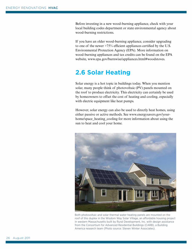
Before investing in a new wood-burning appliance, check with your local building codes department or state environmental agency about wood-burning restrictions.
If you have an older wood-burning appliance, consider upgrading to one of the newer >75% efficient appliances certified by the U.S. Environmental Protection Agency (EPA). More information on wood-burning appliances and tax credits can be found on the EPA website, www.epa.gov/burnwise/appliances.html#woodstoves.
2.6 Solar Heating
Solar energy is a hot topic in buildings today. When you mention solar, many people think of photovoltaic (PV) panels mounted on the roof to produce electricity. This electricity can certainly be used by homeowners to offset the cost of heating and cooling, especially with electric equipment like heat pumps.
However, solar energy can also be used to directly heat homes, using either passive or active methods. See www.energysavers.gov/your-home/space_heating_cooling for more information about using the sun to heat and cool your home.
Both photovoltaic and solar thermal water heating panels are mounted on the roof of this duplex in the Wisdom Way Solar Village, an affordable housing project in western Massachusetts built by Rural Development, Inc. with design assistance from the Consortium for Advanced Residential Buildings (CARB), a Building America research team (Photo source: Steven Winter Associates).
26 August 2011
ENERGY RENOVATIONS HVAC
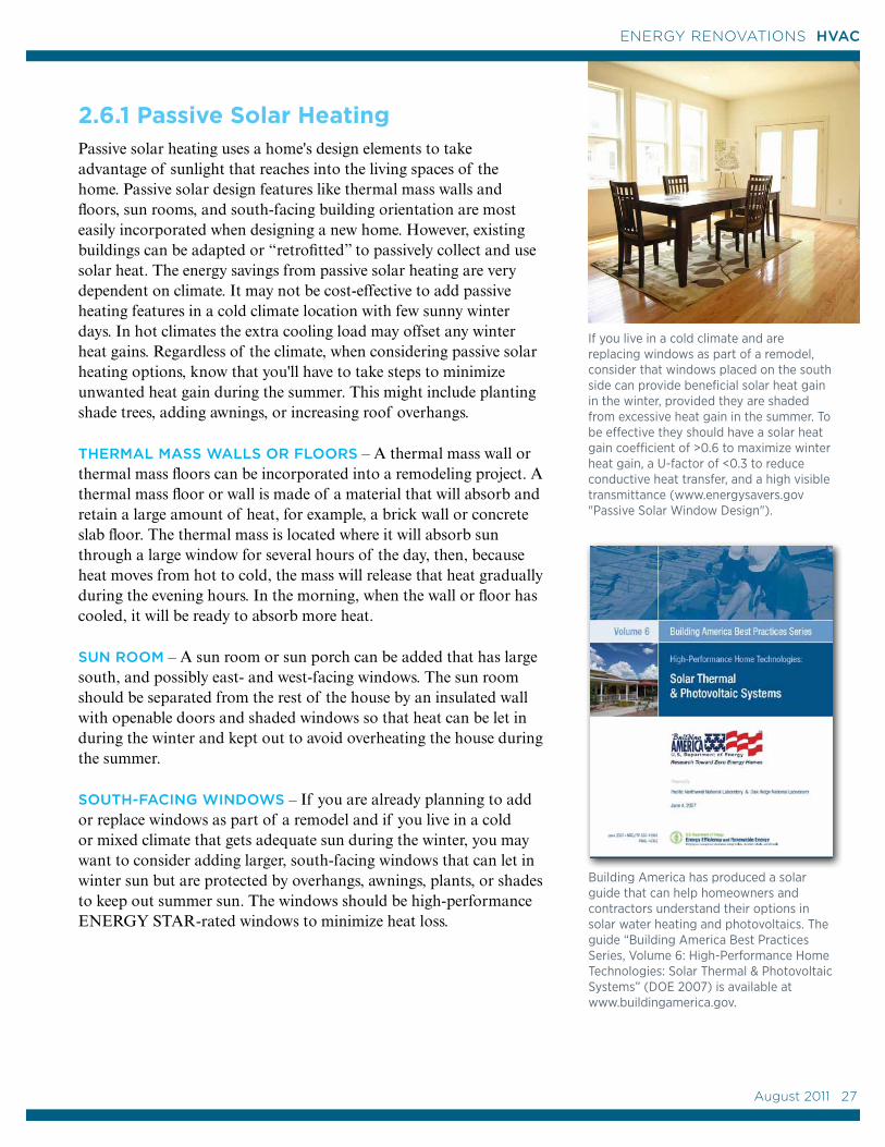
2.6.1 Passive Solar HeatingPassive solar heating uses a home's design elements to take advantage of sunlight that reaches into the living spaces of the home. Passive solar design features like thermal mass walls and floors, sun rooms, and south-facing building orientation are most easily incorporated when designing a new home. However, existing buildings can be adapted or “retrofitted” to passively collect and use solar heat. The energy savings from passive solar heating are very dependent on climate. It may not be cost-effective to add passive heating features in a cold climate location with few sunny winter days. In hot climates the extra cooling load may offset any winter heat gains. Regardless of the climate, when considering passive solar heating options, know that you'll have to take steps to minimize unwanted heat gain during the summer. This might include planting shade trees, adding awnings, or increasing roof overhangs.
THERMAL MASS WALLS OR FLOORS – A thermal mass wall or thermal mass floors can be incorporated into a remodeling project. A thermal mass floor or wall is made of a material that will absorb and retain a large amount of heat, for example, a brick wall or concrete slab floor. The thermal mass is located where it will absorb sun through a large window for several hours of the day, then, because heat moves from hot to cold, the mass will release that heat gradually during the evening hours. In the morning, when the wall or floor has cooled, it will be ready to absorb more heat.
SUN ROOM – A sun room or sun porch can be added that has large south, and possibly east- and west-facing windows. The sun room should be separated from the rest of the house by an insulated wall with openable doors and shaded windows so that heat can be let in during the winter and kept out to avoid overheating the house during the summer.
SOUTH-FACING WINDOWS – If you are already planning to add or replace windows as part of a remodel and if you live in a cold or mixed climate that gets adequate sun during the winter, you may want to consider adding larger, south-facing windows that can let in winter sun but are protected by overhangs, awnings, plants, or shades to keep out summer sun. The windows should be high-performance ENERGY STAR-rated windows to minimize heat loss.
If you live in a cold climate and are replacing windows as part of a remodel, consider that windows placed on the south side can provide beneficial solar heat gain in the winter, provided they are shaded from excessive heat gain in the summer. To be effective they should have a solar heat gain coefficient of >0.6 to maximize winter heat gain, a U-factor of <0.3 to reduce conductive heat transfer, and a high visible transmittance (www.energysavers.gov "Passive Solar Window Design").
Building America has produced a solar guide that can help homeowners and contractors understand their options in solar water heating and photovoltaics. The guide “Building America Best Practices Series, Volume 6: High-Performance Home Technologies: Solar Thermal & Photovoltaic Systems” (DOE 2007) is available at www.buildingamerica.gov.
August 2011 27
27
ENERGY RENOVATIONS HVAC
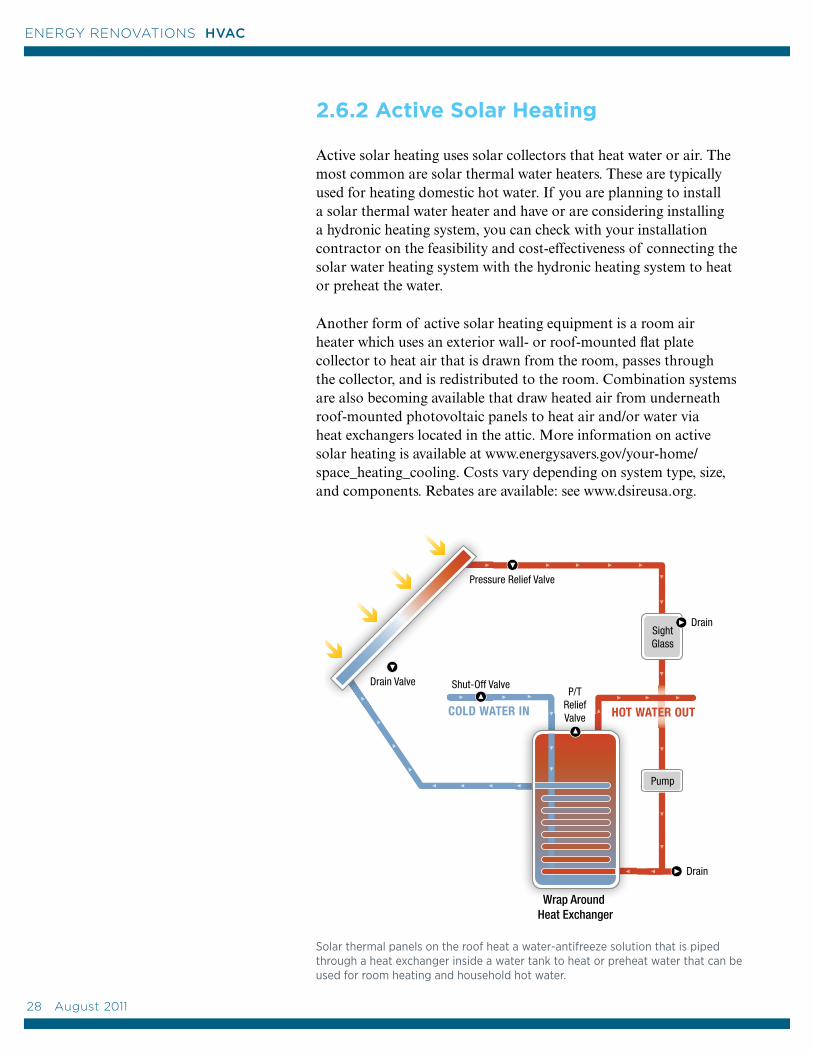
2.6.2 Active Solar Heating
Active solar heating uses solar collectors that heat water or air. The most common are solar thermal water heaters. These are typically used for heating domestic hot water. If you are planning to install a solar thermal water heater and have or are considering installing a hydronic heating system, you can check with your installation contractor on the feasibility and cost-effectiveness of connecting the solar water heating system with the hydronic heating system to heat or preheat the water.
Another form of active solar heating equipment is a room air heater which uses an exterior wall- or roof-mounted flat plate collector to heat air that is drawn from the room, passes through the collector, and is redistributed to the room. Combination systems are also becoming available that draw heated air from underneath roof-mounted photovoltaic panels to heat air and/or water via heat exchangers located in the attic. More information on active solar heating is available at www.energysavers.gov/your-home/space_heating_cooling. Costs vary depending on system type, size, and components. Rebates are available: see www.dsireusa.org.
Solar thermal panels on the roof heat a water-antifreeze solution that is piped through a heat exchanger inside a water tank to heat or preheat water that can be used for room heating and household hot water.
28 August 2011
ENERGY RENOVATIONS HVAC
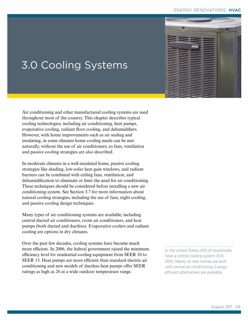
3.0 Cooling Systems
Air conditioning and other manufactured cooling systems are used throughout most of the country. This chapter describes typical cooling technologies, including air conditioning, heat pumps, evaporative cooling, radiant floor cooling, and dehumidifiers. However, with home improvements such as air sealing and insulating, in some climates home cooling needs can be met naturally, without the use of air conditioners, so fans, ventilation and passive cooling strategies are also described.
In moderate climates in a well-insulated home, passive cooling strategies like shading, low-solar heat gain windows, and radiant barriers can be combined with ceiling fans, ventilation, and dehumidification to eliminate or limit the need for air conditioning. These techniques should be considered before installing a new air conditioning system. See Section 3.7 for more information about natural cooling strategies, including the use of fans, night cooling, and passive cooling design techniques.
Many types of air conditioning systems are available, including central ducted air conditioners, room air conditioners, and heat pumps (both ducted and ductless). Evaporative coolers and radiant cooling are options in dry climates.
Over the past few decades, cooling systems have become much more efficient. In 2006, the federal government raised the minimum efficiency level for residential cooling equipment from SEER 10 to SEER 13. Heat pumps are more efficient than standard electric air conditioning and new models of ductless heat pumps offer SEER ratings as high as 26 at a wide outdoor temperature range.
In the United States, 61% of households have a central cooling system (EIA 2011). Nearly all new homes are built with central air conditioning. Energy-efficient alternatives are available.
August 2011 29
29
ENERGY RENOVATIONS HVAC
The following sections describe the advantages and disadvantages of typical mechanical cooling systems and recommendations for maximizing the efficiency of your new system while reducing upfront costs. A contractor can help you determine which system is best for your home.
Your choice will likely be influenced by the age and condition of your current system, the climate zone, cost, other remodeling activities, and energy-efficiency goals. Here are some things to consider.
• If you have a central air conditioning system, existing ductwork might be reused but have the duct system inspected before assuming it is usable. The ducts may have been installed poorly, gotten damaged over time, or be incorrectly sized for a new system. For more information about ducts, see Section 2.1.3.
• If you have a furnace but don’t have central air conditioning, it may be possible to incorporate it with your existing ductwork, depending on cooling load and sizing.
• If you do not have ductwork, installing ducts in an existing home may not be worth the cost (unless you are also installing a central furnace). Ductless mini-split heat pumps may be a good alternative.
• If you only plan on cooling sections or additions to your home, ductless heat pumps work well for zone cooling. Alternatively, window unit air conditioners can be used to cool individual rooms. Look for energy-efficient models.
• If you live in a moderate climate, see Section 3.7 for passive cooling strategies.
The decision tree in Figure 3.1 and the cooling systems characteristics listed in Table 3.1 may also help you in your decision-making process. Table 3.1 presents details on the most common of the cooling systems discussed in this chapter, including an indication of cost. It also gives the Federal minimum efficiency rating (if established), the minimum ENERGY STAR efficiency criteria, and a range of efficiency levels for high-performing models you should look for if you are purchasing a new system.
Cooling Efficiency
The cooling efficiency of air conditioners and heat pumps is referred to as the Seasonal Energy Efficiency Ratio (SEER). SEER is a measure of equipment energy efficiency over the cooling season. It represents the total cooling of a central air-conditioner or heat pump (in Btus) during the normal cooling season as compared to the total electric energy input (in watt-hours) consumed during the same period.
Cooling efficiency can also be measured by the Energy Efficiency Ratio (EER). The EER is a measure of the instantaneous energy efficiency of cooling equipment. EER is the steady-state rate of heat energy removal (e.g., cooling capacity) by the equipment in Btu per hour divided by the steady-state rate of energy input to the equipment in watts. This ratio is expressed in Btu per hour per watt (Btu/hr/watt). EER is used for room units, while SEER is used for centralized units.
The current minimum standard for air conditioner and heat pump cooling efficiency is SEER 13; this went into effect January 23, 2006. Prior to that, the minimum efficiency mandated by the federal government was SEER 10 which took effect in 1992. The standard is scheduled to be revised by DOE in 2011, with new requirements becoming effective in 2016.
30 August 2011
ENERGY RENOVATIONS HVAC
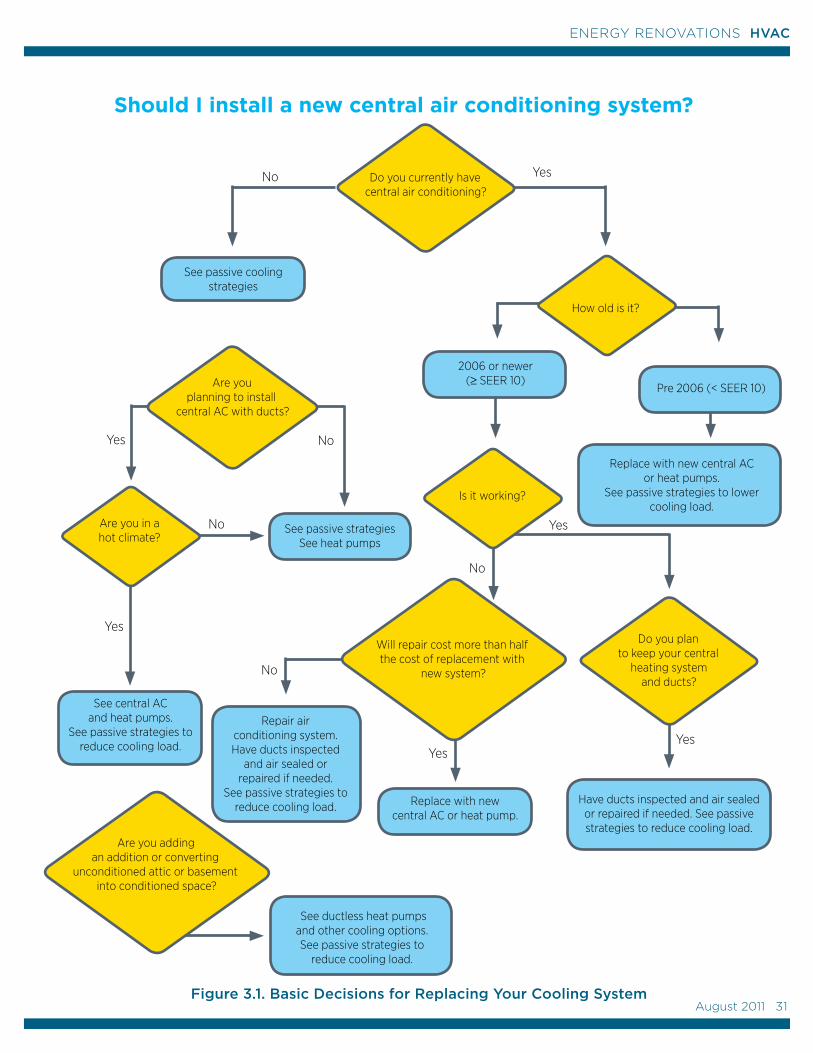
See ductless heat pumps and other cooling options.See passive strategies to
reduce cooling load.
Should I install a new central air conditioning system?
Replace with new central AC or heat pumps.
See passive strategies to lower cooling load.
No
Yes
Yes
Yes
2006 or newer (≥ SEER 10)
Replace with new central AC or heat pump.
No
Yes
Yes
Pre 2006 (< SEER 10)
Have ducts inspected and air sealed or repaired if needed. See passive strategies to reduce cooling load.
See central AC and heat pumps.
See passive strategies to reduce cooling load.
YesNo
Do you currently have central air conditioning?
Are you in a hot climate?
Are you planning to install
central AC with ducts?
How old is it?
Is it working?
Do you plan to keep your central
heating system and ducts?
Will repair cost more than half the cost of replacement with
new system?
Are you adding an addition or converting
unconditioned attic or basement into conditioned space?
No
Yes
See passive strategies See heat pumps
See passive cooling strategies
Repair air conditioning system.Have ducts inspected
and air sealed or repaired if needed.
See passive strategies to reduce cooling load.
No
Figure 3.1. Basic Decisions for Replacing Your Cooling SystemAugust 2011 31
31
ENERGY RENOVATIONS HVAC
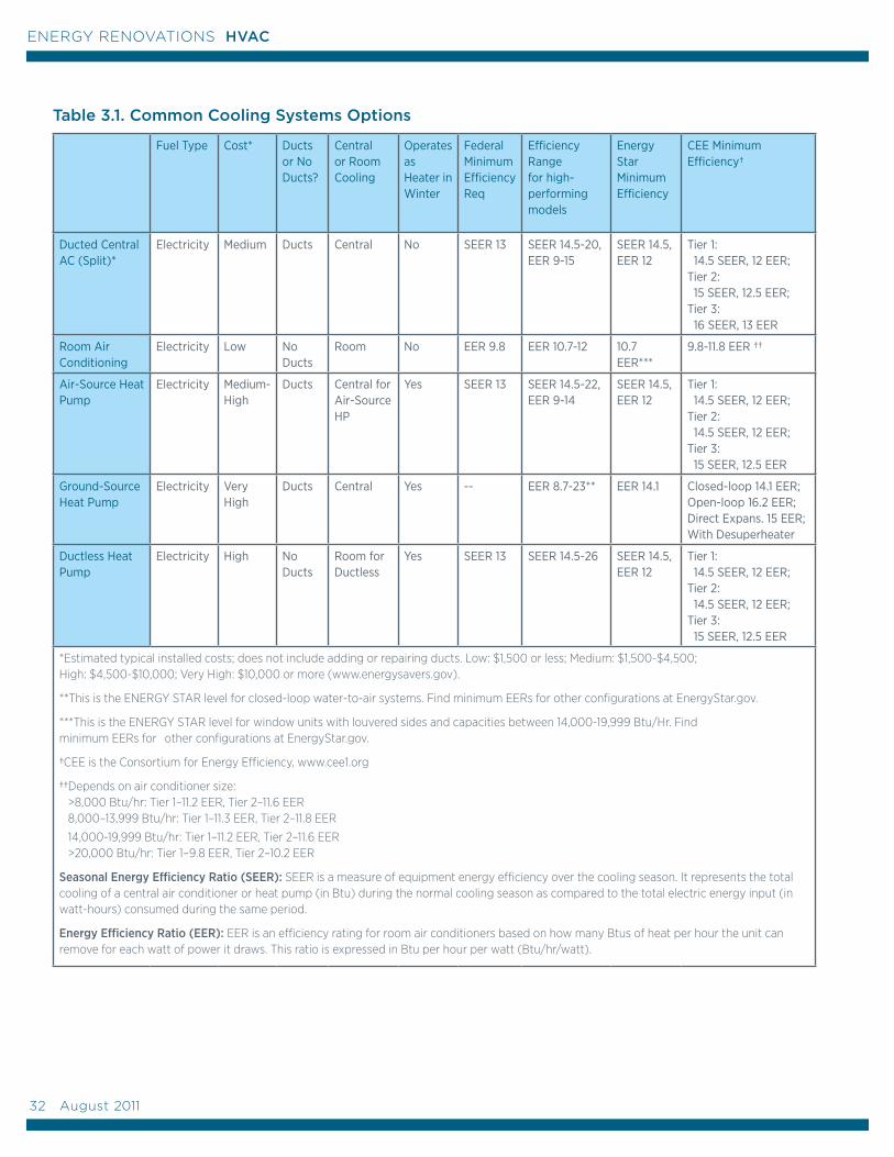
Table 3.1. Common Cooling Systems Options
Fuel Type Cost* Ducts or No Ducts?
Central or Room Cooling
Operates as Heater in Winter
Federal Minimum Efficiency Req
Efficiency Range for high-performing models
Energy Star Minimum Efficiency
CEE Minimum Efficiency†
Ducted Central AC (Split)*
Electricity Medium Ducts Central No SEER 13 SEER 14.5-20, EER 9-15
SEER 14.5, EER 12
Tier 1: 14.5 SEER, 12 EER; Tier 2: 15 SEER, 12.5 EER; Tier 3: 16 SEER, 13 EER
Room Air Conditioning
Electricity Low No Ducts
Room No EER 9.8 EER 10.7-12 10.7 EER***
9.8-11.8 EER ††
Air-Source Heat Pump
Electricity Medium-High
Ducts Central for Air-Source HP
Yes SEER 13 SEER 14.5-22, EER 9-14
SEER 14.5, EER 12
Tier 1: 14.5 SEER, 12 EER; Tier 2: 14.5 SEER, 12 EER; Tier 3: 15 SEER, 12.5 EER
Ground-Source Heat Pump
Electricity Very High
Ducts Central Yes -- EER 8.7-23** EER 14.1 Closed-loop 14.1 EER; Open-loop 16.2 EER; Direct Expans. 15 EER; With Desuperheater
Ductless Heat Pump
Electricity High No Ducts
Room for Ductless
Yes SEER 13 SEER 14.5-26 SEER 14.5, EER 12
Tier 1: 14.5 SEER, 12 EER; Tier 2: 14.5 SEER, 12 EER; Tier 3: 15 SEER, 12.5 EER
*Estimated typical installed costs; does not include adding or repairing ducts. Low: $1,500 or less; Medium: $1,500-$4,500; High: $4,500-$10,000; Very High: $10,000 or more (www.energysavers.gov).
**This is the ENERGY STAR level for closed-loop water-to-air systems. Find minimum EERs for other configurations at EnergyStar.gov.
***This is the ENERGY STAR level for window units with louvered sides and capacities between 14,000-19,999 Btu/Hr. Find minimum EERs for other configurations at EnergyStar.gov.
†CEE is the Consortium for Energy Efficiency, www.cee1.org
††Depends on air conditioner size: >8,000 Btu/hr: Tier 1–11.2 EER, Tier 2–11.6 EER 8,000–13,999 Btu/hr: Tier 1–11.3 EER, Tier 2–11.8 EER
14,000-19,999 Btu/hr: Tier 1–11.2 EER, Tier 2–11.6 EER >20,000 Btu/hr: Tier 1–9.8 EER, Tier 2–10.2 EER
Seasonal Energy Efficiency Ratio (SEER): SEER is a measure of equipment energy efficiency over the cooling season. It represents the total cooling of a central air conditioner or heat pump (in Btu) during the normal cooling season as compared to the total electric energy input (in watt-hours) consumed during the same period.
Energy Efficiency Ratio (EER): EER is an efficiency rating for room air conditioners based on how many Btus of heat per hour the unit can remove for each watt of power it draws. This ratio is expressed in Btu per hour per watt (Btu/hr/watt).
32 August 2011
ENERGY RENOVATIONS HVAC
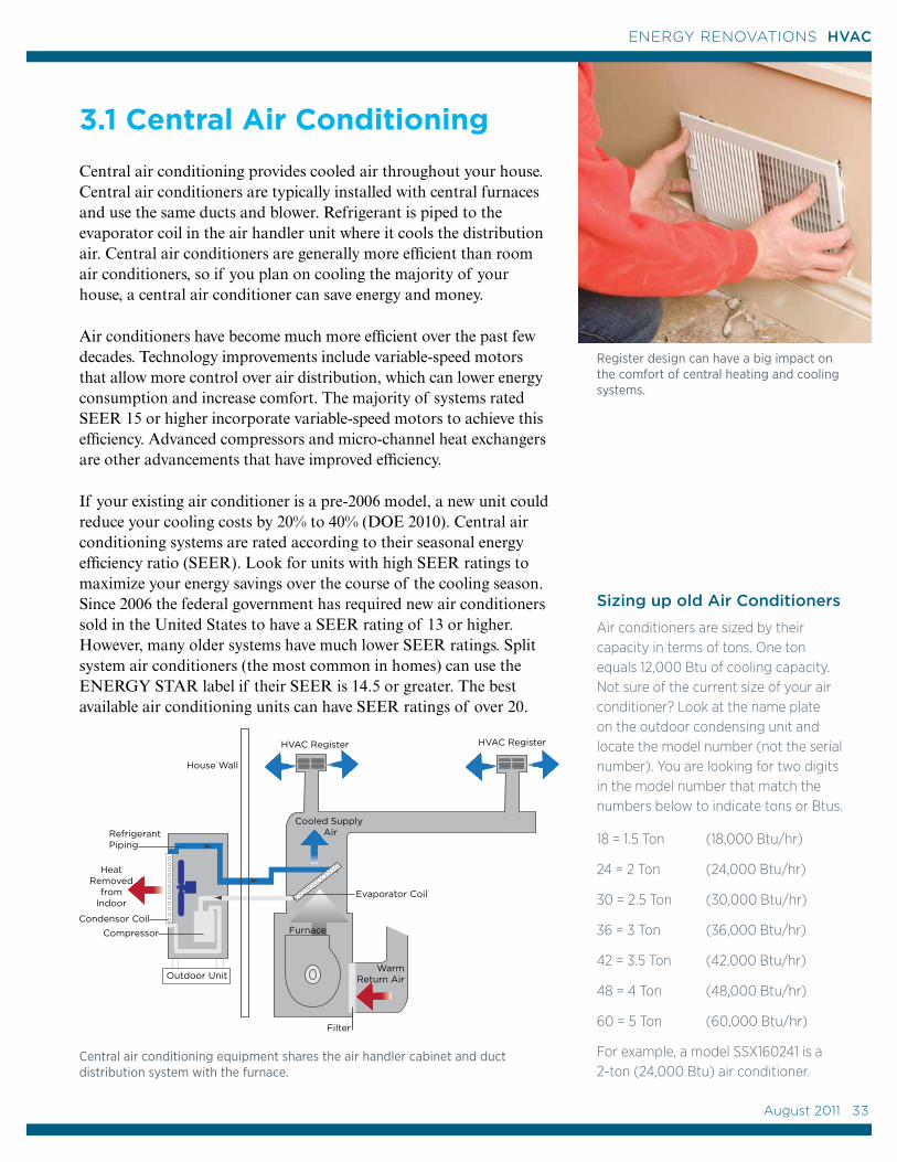
Compressor
HeatRemoved
fromIndoor
Outdoor Unit
Refrigerant Piping
Cooled Supply Air
Evaporator Coil
Furnace
Filter
WarmReturn Air
Condensor Coil
House Wall
HVAC Register HVAC Register
3.1 Central Air Conditioning
Central air conditioning provides cooled air throughout your house. Central air conditioners are typically installed with central furnaces and use the same ducts and blower. Refrigerant is piped to the evaporator coil in the air handler unit where it cools the distribution air. Central air conditioners are generally more efficient than room air conditioners, so if you plan on cooling the majority of your house, a central air conditioner can save energy and money.
Air conditioners have become much more efficient over the past few decades. Technology improvements include variable-speed motors that allow more control over air distribution, which can lower energy consumption and increase comfort. The majority of systems rated SEER 15 or higher incorporate variable-speed motors to achieve this efficiency. Advanced compressors and micro-channel heat exchangers are other advancements that have improved efficiency.
If your existing air conditioner is a pre-2006 model, a new unit could reduce your cooling costs by 20% to 40% (DOE 2010). Central air conditioning systems are rated according to their seasonal energy efficiency ratio (SEER). Look for units with high SEER ratings to maximize your energy savings over the course of the cooling season. Since 2006 the federal government has required new air conditioners sold in the United States to have a SEER rating of 13 or higher. However, many older systems have much lower SEER ratings. Split system air conditioners (the most common in homes) can use the ENERGY STAR label if their SEER is 14.5 or greater. The best available air conditioning units can have SEER ratings of over 20.
Sizing up old Air Conditioners
Air conditioners are sized by their capacity in terms of tons. One ton equals 12,000 Btu of cooling capacity. Not sure of the current size of your air conditioner? Look at the name plate on the outdoor condensing unit and locate the model number (not the serial number). You are looking for two digits in the model number that match the numbers below to indicate tons or Btus.
18 = 1.5 Ton (18,000 Btu/hr)
24 = 2 Ton (24,000 Btu/hr)
30 = 2.5 Ton (30,000 Btu/hr)
36 = 3 Ton (36,000 Btu/hr)
42 = 3.5 Ton (42,000 Btu/hr)
48 = 4 Ton (48,000 Btu/hr)
60 = 5 Ton (60,000 Btu/hr)
For example, a model SSX160241 is a 2-ton (24,000 Btu) air conditioner.
Central air conditioning equipment shares the air handler cabinet and duct distribution system with the furnace.
Register design can have a big impact on the comfort of central heating and cooling systems.
August 2011 33
33
ENERGY RENOVATIONS HVAC
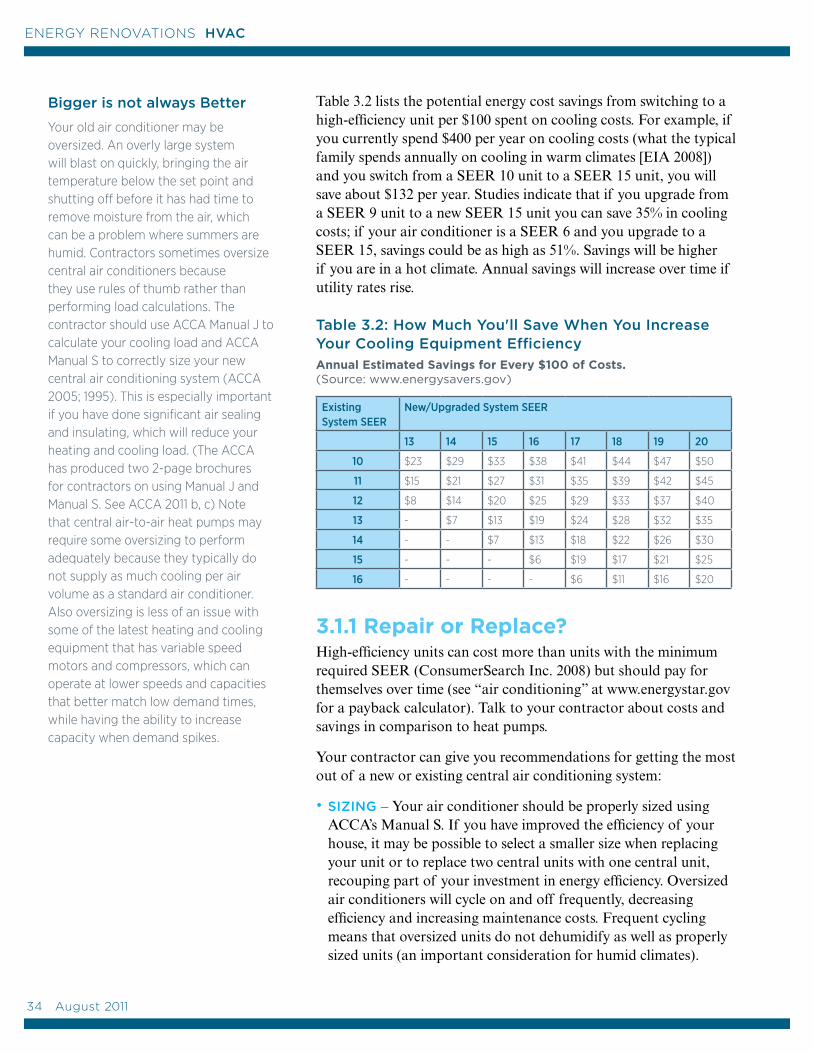
Table 3.2 lists the potential energy cost savings from switching to a high-efficiency unit per $100 spent on cooling costs. For example, if you currently spend $400 per year on cooling costs (what the typical family spends annually on cooling in warm climates [EIA 2008]) and you switch from a SEER 10 unit to a SEER 15 unit, you will save about $132 per year. Studies indicate that if you upgrade from a SEER 9 unit to a new SEER 15 unit you can save 35% in cooling costs; if your air conditioner is a SEER 6 and you upgrade to a SEER 15, savings could be as high as 51%. Savings will be higher if you are in a hot climate. Annual savings will increase over time if utility rates rise.
Table 3.2: How Much You'll Save When You Increase Your Cooling Equipment Efficiency
Annual Estimated Savings for Every $100 of Costs. (Source: www.energysavers.gov)
Existing System SEER
New/Upgraded System SEER
13 14 15 16 17 18 19 20
10 $23 $29 $33 $38 $41 $44 $47 $50
11 $15 $21 $27 $31 $35 $39 $42 $45
12 $8 $14 $20 $25 $29 $33 $37 $40
13 - $7 $13 $19 $24 $28 $32 $35
14 - - $7 $13 $18 $22 $26 $30
15 - - - $6 $19 $17 $21 $25
16 - - - - $6 $11 $16 $20
3.1.1 Repair or Replace?High-efficiency units can cost more than units with the minimum required SEER (ConsumerSearch Inc. 2008) but should pay for themselves over time (see “air conditioning” at www.energystar.gov for a payback calculator). Talk to your contractor about costs and savings in comparison to heat pumps.
Your contractor can give you recommendations for getting the most out of a new or existing central air conditioning system:
• SIZING – Your air conditioner should be properly sized using ACCA’s Manual S. If you have improved the efficiency of your house, it may be possible to select a smaller size when replacing your unit or to replace two central units with one central unit, recouping part of your investment in energy efficiency. Oversized air conditioners will cycle on and off frequently, decreasing efficiency and increasing maintenance costs. Frequent cycling means that oversized units do not dehumidify as well as properly sized units (an important consideration for humid climates).
Bigger is not always Better
Your old air conditioner may be oversized. An overly large system will blast on quickly, bringing the air temperature below the set point and shutting off before it has had time to remove moisture from the air, which can be a problem where summers are humid. Contractors sometimes oversize central air conditioners because they use rules of thumb rather than performing load calculations. The contractor should use ACCA Manual J to calculate your cooling load and ACCA Manual S to correctly size your new central air conditioning system (ACCA 2005; 1995). This is especially important if you have done significant air sealing and insulating, which will reduce your heating and cooling load. (The ACCA has produced two 2-page brochures for contractors on using Manual J and Manual S. See ACCA 2011 b, c) Note that central air-to-air heat pumps may require some oversizing to perform adequately because they typically do not supply as much cooling per air volume as a standard air conditioner. Also oversizing is less of an issue with some of the latest heating and cooling equipment that has variable speed motors and compressors, which can operate at lower speeds and capacities that better match low demand times, while having the ability to increase capacity when demand spikes.
34 August 2011
ENERGY RENOVATIONS HVAC
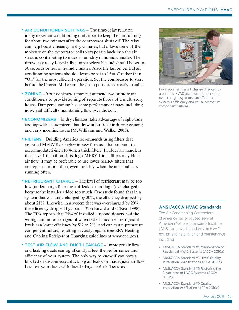
• AIR CONDITIONER SETTINGS – The time-delay relay on many newer air conditioning units is set to keep the fan running for about two minutes after the compressor shuts off. The relay can help boost efficiency in dry climates, but allows some of the moisture on the evaporator coil to evaporate back into the air stream, contributing to indoor humidity in humid climates. The time-delay relay is typically jumper selectable and should be set to 30 seconds or less in humid climates. Also, the fan on central air conditioning systems should always be set to “Auto” rather than “On” for the most efficient operation. Set the compressor to start before the blower. Make sure the drain pans are correctly installed.
• ZONING – Your contractor may recommend two or more air conditioners to provide zoning of separate floors of a multi-story house. Dampered zoning has some performance issues, including noise and difficulty maintaining flow over the coil.
• ECONOMIZERS – In dry climates, take advantage of night-time cooling with economizers that draw in outside air during evening and early morning hours (McWilliams and Walker 2005).
• FILTERS – Building America recommends using filters that are rated MERV 8 or higher in new furnaces that are built to accommodate 2-inch to 4-inch thick filters. In older air handlers that have 1-inch filter slots, high-MERV 1-inch filters may block air flow; it may be preferable to use lower MERV filters that are replaced more often, even monthly, when the air handler is running often.
• REFRIGERANT CHARGE – The level of refrigerant may be too low (undercharged) because of leaks or too high (overcharged) because the installer added too much. One study found that in a system that was undercharged by 20%, the efficiency dropped by about 21%. Likewise, in a system that was overcharged by 20%, the efficiency dropped by about 12% (Farzad and O’Neal 1998). The EPA reports that 75% of installed air conditioners had the wrong amount of refrigerant when tested. Incorrect refrigerant levels can lower efficiency by 5% to 20% and can cause premature component failure, resulting in costly repairs (see EPA Heating and Cooling Refrigerant Charging guidelines at www.epa.gov).
• TEST AIR FLOW AND DUCT LEAKAGE – Improper air flow and leaking ducts can significantly affect the performance and efficiency of your system. The only way to know if you have a blocked or disconnected duct, big air leaks, or inadequate air flow is to test your ducts with duct leakage and air flow tests.
Have your refrigerant charge checked by a certified HVAC technician. Under- and over-charged systems can affect the system’s efficiency and cause premature component failures.
ANSI/ACCA HVAC StandardsThe Air Conditioning Contractors of America has produced several American National Standards Institute (ANSI) approved standards on HVAC equipment installation and maintenance including
• ANSI/ACCA Standard #4 Maintenance of Residential HVAC Systems (ACCA 2010a)
• ANSI/ACCA Standard #5 HVAC Quality Installation Specification (ACCA 2010b)
• ANSI/ACCA Standard #6 Restoring the Cleanliness of HVAC Systems (ACCA 2010c)
• ANSI/ACCA Standard #9 Quality Installation Verification (ACCA 2010d).
August 2011 35
35
ENERGY RENOVATIONS HVAC
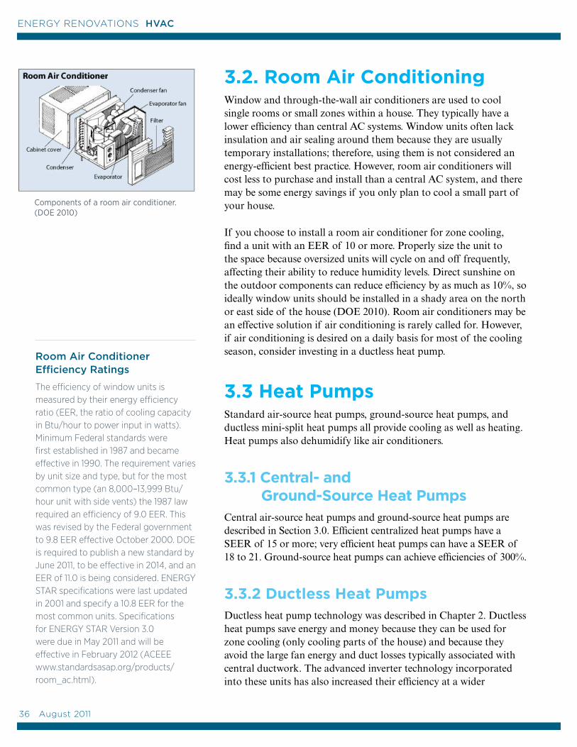
3.2. Room Air ConditioningWindow and through-the-wall air conditioners are used to cool single rooms or small zones within a house. They typically have a lower efficiency than central AC systems. Window units often lack insulation and air sealing around them because they are usually temporary installations; therefore, using them is not considered an energy-efficient best practice. However, room air conditioners will cost less to purchase and install than a central AC system, and there may be some energy savings if you only plan to cool a small part of your house.
If you choose to install a room air conditioner for zone cooling, find a unit with an EER of 10 or more. Properly size the unit to the space because oversized units will cycle on and off frequently, affecting their ability to reduce humidity levels. Direct sunshine on the outdoor components can reduce efficiency by as much as 10%, so ideally window units should be installed in a shady area on the north or east side of the house (DOE 2010). Room air conditioners may be an effective solution if air conditioning is rarely called for. However, if air conditioning is desired on a daily basis for most of the cooling season, consider investing in a ductless heat pump.
3.3 Heat Pumps Standard air-source heat pumps, ground-source heat pumps, and ductless mini-split heat pumps all provide cooling as well as heating. Heat pumps also dehumidify like air conditioners.
3.3.1 Central- and Ground-Source Heat PumpsCentral air-source heat pumps and ground-source heat pumps are described in Section 3.0. Efficient centralized heat pumps have a SEER of 15 or more; very efficient heat pumps can have a SEER of 18 to 21. Ground-source heat pumps can achieve efficiencies of 300%.
3.3.2 Ductless Heat PumpsDuctless heat pump technology was described in Chapter 2. Ductless heat pumps save energy and money because they can be used for zone cooling (only cooling parts of the house) and because they avoid the large fan energy and duct losses typically associated with central ductwork. The advanced inverter technology incorporated into these units has also increased their efficiency at a wider
Room Air Conditioner Efficiency Ratings
The efficiency of window units is measured by their energy efficiency ratio (EER, the ratio of cooling capacity in Btu/hour to power input in watts). Minimum Federal standards were first established in 1987 and became effective in 1990. The requirement varies by unit size and type, but for the most common type (an 8,000–13,999 Btu/hour unit with side vents) the 1987 law required an efficiency of 9.0 EER. This was revised by the Federal government to 9.8 EER effective October 2000. DOE is required to publish a new standard by June 2011, to be effective in 2014, and an EER of 11.0 is being considered. ENERGY STAR specifications were last updated in 2001 and specify a 10.8 EER for the most common units. Specifications for ENERGY STAR Version 3.0 were due in May 2011 and will be effective in February 2012 (ACEEE www.standardsasap.org/products/room_ac.html).
Components of a room air conditioner. (DOE 2010)
36 August 2011
ENERGY RENOVATIONS HVAC
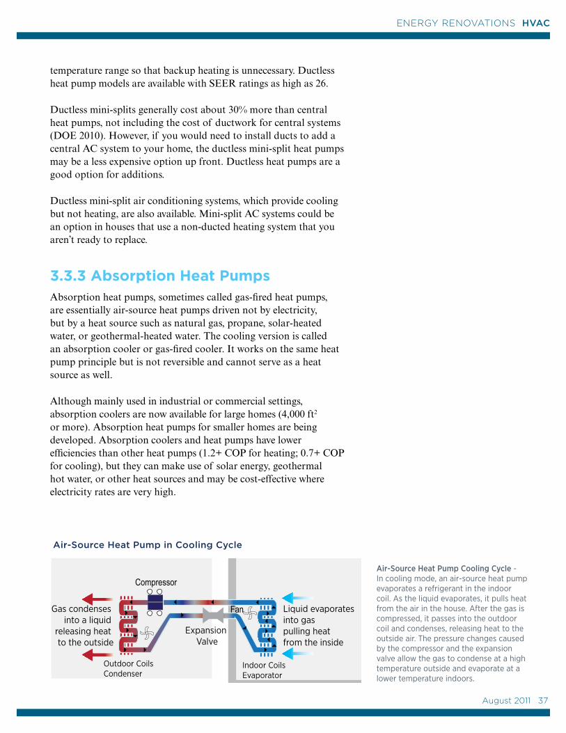
Outdoor CoilsEvaporator
Compressor
Expansion Valve
Indoor Coils Condenser
Gas condenses into a liquid, releasing heat inside
Gas condenses into a liquid
releasing heat to the outside
Compressor
Liquid evaporatesinto gas pulling heat from the inside
Fan
Liquid evaporates
into gas,pulling heat from outside
Indoor CoilsEvaporator
Expansion Valve
Outdoor CoilsCondenser
Air-Source Heat Pump Cooling Cycle -In cooling mode, an air-source heat pump evaporates a refrigerant in the indoor coil. As the liquid evaporates, it pulls heat from the air in the house. After the gas is compressed, it passes into the outdoor coil and condenses, releasing heat to the outside air. The pressure changes caused by the compressor and the expansion valve allow the gas to condense at a high temperature outside and evaporate at a lower temperature indoors.
Air-Source Heat Pump in Cooling Cycle
temperature range so that backup heating is unnecessary. Ductless heat pump models are available with SEER ratings as high as 26.
Ductless mini-splits generally cost about 30% more than central heat pumps, not including the cost of ductwork for central systems (DOE 2010). However, if you would need to install ducts to add a central AC system to your home, the ductless mini-split heat pumps may be a less expensive option up front. Ductless heat pumps are a good option for additions.
Ductless mini-split air conditioning systems, which provide cooling but not heating, are also available. Mini-split AC systems could be an option in houses that use a non-ducted heating system that you aren’t ready to replace.
3.3.3 Absorption Heat PumpsAbsorption heat pumps, sometimes called gas-fired heat pumps, are essentially air-source heat pumps driven not by electricity, but by a heat source such as natural gas, propane, solar-heated water, or geothermal-heated water. The cooling version is called an absorption cooler or gas-fired cooler. It works on the same heat pump principle but is not reversible and cannot serve as a heat source as well.
Although mainly used in industrial or commercial settings, absorption coolers are now available for large homes (4,000 ft2 or more). Absorption heat pumps for smaller homes are being developed. Absorption coolers and heat pumps have lower efficiencies than other heat pumps (1.2+ COP for heating; 0.7+ COP for cooling), but they can make use of solar energy, geothermal hot water, or other heat sources and may be cost-effective where electricity rates are very high.
August 2011 37
37
ENERGY RENOVATIONS HVAC
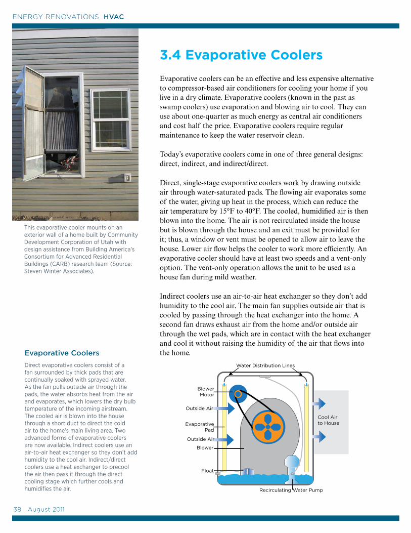
3.4 Evaporative Coolers
Evaporative coolers can be an effective and less expensive alternative to compressor-based air conditioners for cooling your home if you live in a dry climate. Evaporative coolers (known in the past as swamp coolers) use evaporation and blowing air to cool. They can use about one-quarter as much energy as central air conditioners and cost half the price. Evaporative coolers require regular maintenance to keep the water reservoir clean.
Today’s evaporative coolers come in one of three general designs: direct, indirect, and indirect/direct.
Direct, single-stage evaporative coolers work by drawing outside air through water-saturated pads. The flowing air evaporates some of the water, giving up heat in the process, which can reduce the air temperature by 15°F to 40°F. The cooled, humidified air is then blown into the home. The air is not recirculated inside the house but is blown through the house and an exit must be provided for it; thus, a window or vent must be opened to allow air to leave the house. Lower air flow helps the cooler to work more efficiently. An evaporative cooler should have at least two speeds and a vent-only option. The vent-only operation allows the unit to be used as a house fan during mild weather.
Indirect coolers use an air-to-air heat exchanger so they don’t add humidity to the cool air. The main fan supplies outside air that is cooled by passing through the heat exchanger into the home. A second fan draws exhaust air from the home and/or outside air through the wet pads, which are in contact with the heat exchanger and cool it without raising the humidity of the air that flows into the home.
EvaporativePad
Blower
Water Distribution Lines
Recirculating Water Pump
Float
Outside Air
Outside Air
Cool Air to House
BlowerMotor
This evaporative cooler mounts on an exterior wall of a home built by Community Development Corporation of Utah with design assistance from Building America's Consortium for Advanced Residential Buildings (CARB) research team (Source: Steven Winter Associates).
Evaporative Coolers
Direct evaporative coolers consist of a fan surrounded by thick pads that are continually soaked with sprayed water. As the fan pulls outside air through the pads, the water absorbs heat from the air and evaporates, which lowers the dry bulb temperature of the incoming airstream. The cooled air is blown into the house through a short duct to direct the cold air to the home’s main living area. Two advanced forms of evaporative coolers are now available. Indirect coolers use an air-to-air heat exchanger so they don’t add humidity to the cool air. Indirect/direct coolers use a heat exchanger to precool the air then pass it through the direct cooling stage which further cools and humidifies the air.
38 August 2011
ENERGY RENOVATIONS HVAC
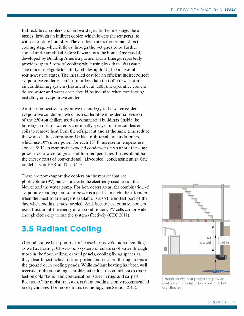
FOR SALE
Hot fluid out
Cold fluid in
Indirect/direct coolers cool in two stages. In the first stage, the air passes through an indirect cooler, which lowers the temperature without adding humidity. The air then enters the second, direct cooling stage where it flows through the wet pads to be further cooled and humidified before flowing into the home. One model, developed by Building America partner Davis Energy, reportedly provides up to 5 tons of cooling while using less than 1600 watts. The model is eligible for utility rebates up to $1,100 in several south-western states. The installed cost for an efficient indirect/direct evaporative cooler is similar to or less than that of a new central air conditioning system (Eastment et al. 2005). Evaporative coolers do use water and water costs should be included when considering installing an evaporative cooler.
Another innovative evaporative technology is the water-cooled evaporative condenser, which is a scaled-down residential version of the 250-ton chillers used on commercial buildings. Inside the housing, a mist of water is continually sprayed on the condenser coils to remove heat from the refrigerant and at the same time reduce the work of the compressor. Unlike traditional air conditioners, which use 10% more power for each 10° F increase in temperature above 95° F, an evaporative-cooled condenser draws about the same power over a wide range of outdoor temperatures. It uses about half the energy costs of conventional “air-cooled” condensing units. One model has an EER of 17 at 95°F.
There are now evaporative coolers on the market that use photovoltaic (PV) panels to create the electricity used to run the blower and the water pump. For hot, desert areas, the combination of evaporative cooling and solar power is a perfect match: the afternoon, when the most solar energy is available, is also the hottest part of the day, when cooling is most needed. And, because evaporative coolers use a fraction of the energy of air conditioners, PV cells can provide enough electricity to run the system effectively (CEC 2011).
3.5 Radiant Cooling
Ground-source heat pumps can be used to provide radiant cooling as well as heating. Closed-loop systems circulate cool water through tubes in the floor, ceiling, or wall panels, cooling living spaces as they absorb heat, which is transported and released through loops in the ground or in cooling ponds. While radiant heating has been well received, radiant cooling is problematic due to comfort issues (bare feet on cold floors) and condensation issues in rugs and carpets. Because of the moisture issues, radiant cooling is only recommended in dry climates. For more on this technology, see Section 2.4.2.
Ground-source heat pumps can provide cool water for radiant floor cooling in hot dry climates.
August 2011 39
39
ENERGY RENOVATIONS HVAC
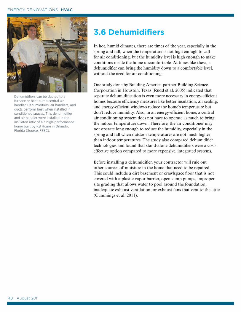
3.6 Dehumidifiers
In hot, humid climates, there are times of the year, especially in the spring and fall, when the temperature is not high enough to call for air conditioning, but the humidity level is high enough to make conditions inside the home uncomfortable. At times like these, a dehumidifier can bring the humidity down to a comfortable level, without the need for air conditioning.
One study done by Building America partner Building Science Corporation in Houston, Texas (Rudd et al. 2005) indicated that separate dehumidification is even more necessary in energy-efficient homes because efficiency measures like better insulation, air sealing, and energy-efficient windows reduce the home’s temperature but don’t reduce humidity. Also, in an energy-efficient home, a central air conditioning system does not have to operate as much to bring the indoor temperature down. Therefore, the air conditioner may not operate long enough to reduce the humidity, especially in the spring and fall when outdoor temperatures are not much higher than indoor temperatures. The study also compared dehumidifier technologies and found that stand-alone dehumidifiers were a cost-effective option compared to more expensive, integrated systems.
Before installing a dehumidifier, your contractor will rule out other sources of moisture in the home that need to be repaired. This could include a dirt basement or crawlspace floor that is not covered with a plastic vapor barrier, open sump pumps, improper site grading that allows water to pool around the foundation, inadequate exhaust ventilation, or exhaust fans that vent to the attic (Cummings et al. 2011).
Dehumidifiers can be ducted to a furnace or heat pump central air handler. Dehumidifiers, air handlers, and ducts perform best when installed in conditioned spaces. This dehumidifier and air handler were installed in the insulated attic of a a high-performance home built by KB Home in Orlando, Florida (Source: FSEC).
40 August 2011
ENERGY RENOVATIONS HVAC
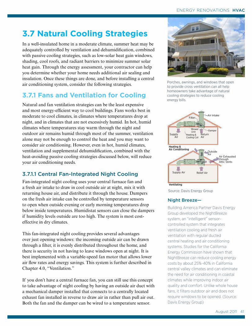
3.7 Natural Cooling Strategies In a well-insulated home in a moderate climate, summer heat may be adequately controlled by ventilation and dehumidification, combined with passive cooling strategies, such as low-solar heat gain windows, shading, cool roofs, and radiant barriers to minimize summer solar heat gain. Through the energy assessment, your contractor can help you determine whether your home needs additional air sealing and insulation. Once these things are done, and before installing a central air conditioning system, consider the following strategies.
3.7.1 Fans and Ventilation for CoolingNatural and fan ventilation strategies can be the least expensive and most energy-efficient way to cool buildings. Fans works best in moderate to cool climates, in climates where temperatures drop at night, and in climates that are not excessively humid. In hot, humid climates where temperatures stay warm through the night and outdoor air remains humid through most of the summer, ventilation alone may not be enough to control the heat and you may want to consider air conditioning. However, even in hot, humid climates, ventilation and supplemental dehumidification, combined with the heat-avoiding passive cooling strategies discussed below, will reduce your air conditioning needs.
3.7.1.1 Central Fan-Integrated Night Cooling Fan-integrated night cooling uses your central furnace fan and a fresh air intake to draw in cool outside air at night, mix it with returning house air, and distribute it through the house. Dampers on the fresh air intake can be controlled by temperature sensors to open when outside evening or early morning temperatures drop below inside temperatures. Humidistat sensors can close the dampers if humidity levels outside are too high. The system is most cost-effective in dry climates.
This fan-integrated night cooling provides several advantages over just opening windows: the incoming outside air can be drawn through a filter, it is evenly distributed throughout the home, and there is security in not having to leave windows open at night. It is best implemented with a variable-speed fan motor that allows lower air flow rates and energy savings. This system is further described in Chapter 4.0, “Ventilation.”
If you don’t have a central furnace fan, you can still use this concept to take advantage of night cooling by having an outside air duct with a mechanical damper installed that connects to a centrally located exhaust fan installed in reverse to draw air in rather than pull air out. Both the fan and the damper can be wired to a temperature sensor.
Night Breeze—
Building America Partner Davis Energy Group developed the NightBreeze system, an “intelligent” sensor-controlled system that integrates ventilation cooling and fresh air ventilation with regular ducted central heating and air conditioning systems. Studies for the California Energy Commission have shown that NightBreeze can reduce cooling energy costs by about 25%-40% in California central valley climates and can eliminate the need for air conditioning in coastal climates while improving indoor air quality and comfort. Unlike whole house fans, it filters outdoor air and does not require windows to be opened. (Source: Davis Energy Group)
Air IntakeFilter
SupplyAir
Return Air
DamperBlower Unit
Heating & Cooling Coil
Heating & Air Conditioning
Outside Air
Air ExhaustedthroughAttic Vents
Relief AirSupply Air
Ventilating
Source: Davis Energy Group
Porches, awnings, and windows that open to provide cross ventilation can all help homeowners take advantage of natural cooling strategies to reduce cooling energy bills.
August 2011 41
41
ENERGY RENOVATIONS HVAC
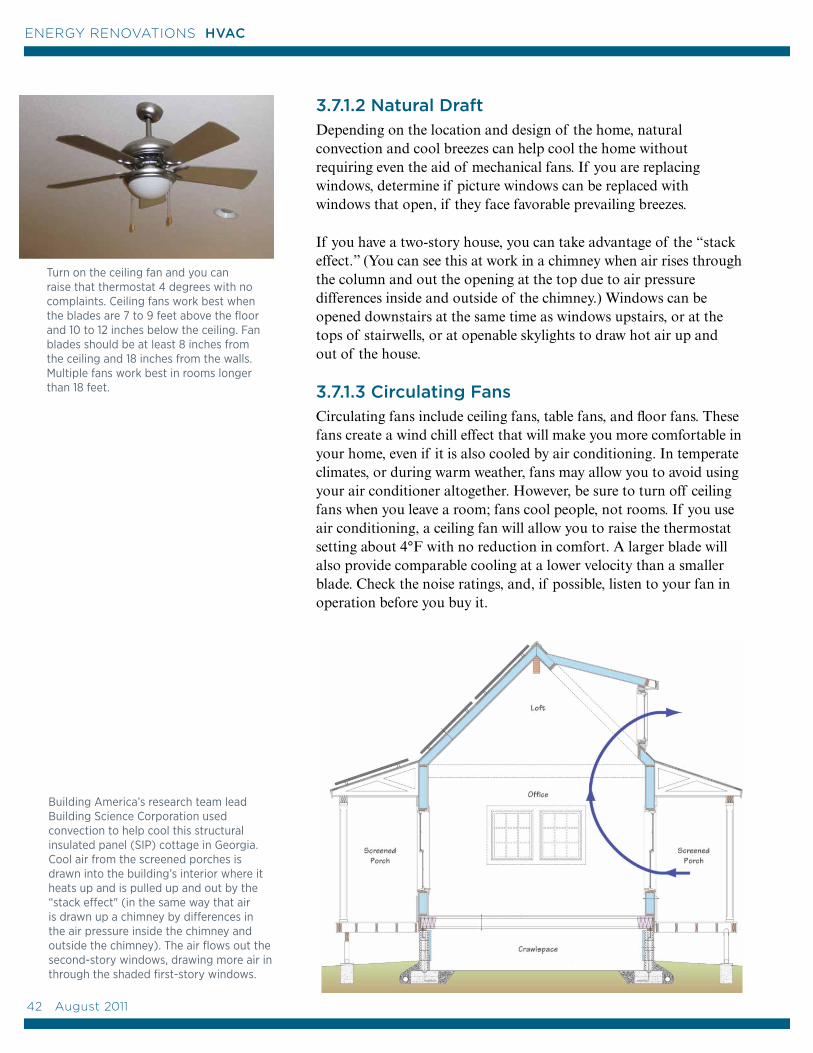
3.7.1.2 Natural Draft Depending on the location and design of the home, natural convection and cool breezes can help cool the home without requiring even the aid of mechanical fans. If you are replacing windows, determine if picture windows can be replaced with windows that open, if they face favorable prevailing breezes.
If you have a two-story house, you can take advantage of the “stack effect.” (You can see this at work in a chimney when air rises through the column and out the opening at the top due to air pressure differences inside and outside of the chimney.) Windows can be opened downstairs at the same time as windows upstairs, or at the tops of stairwells, or at openable skylights to draw hot air up and out of the house.
3.7.1.3 Circulating Fans Circulating fans include ceiling fans, table fans, and floor fans. These fans create a wind chill effect that will make you more comfortable in your home, even if it is also cooled by air conditioning. In temperate climates, or during warm weather, fans may allow you to avoid using your air conditioner altogether. However, be sure to turn off ceiling fans when you leave a room; fans cool people, not rooms. If you use air conditioning, a ceiling fan will allow you to raise the thermostat setting about 4°F with no reduction in comfort. A larger blade will also provide comparable cooling at a lower velocity than a smaller blade. Check the noise ratings, and, if possible, listen to your fan in operation before you buy it.
Turn on the ceiling fan and you can raise that thermostat 4 degrees with no complaints. Ceiling fans work best when the blades are 7 to 9 feet above the floor and 10 to 12 inches below the ceiling. Fan blades should be at least 8 inches from the ceiling and 18 inches from the walls. Multiple fans work best in rooms longer than 18 feet.
Building America’s research team lead Building Science Corporation used convection to help cool this structural insulated panel (SIP) cottage in Georgia. Cool air from the screened porches is drawn into the building’s interior where it heats up and is pulled up and out by the “stack effect" (in the same way that air is drawn up a chimney by differences in the air pressure inside the chimney and outside the chimney). The air flows out the second-story windows, drawing more air in through the shaded first-story windows.
42 August 2011
ENERGY RENOVATIONS HVAC
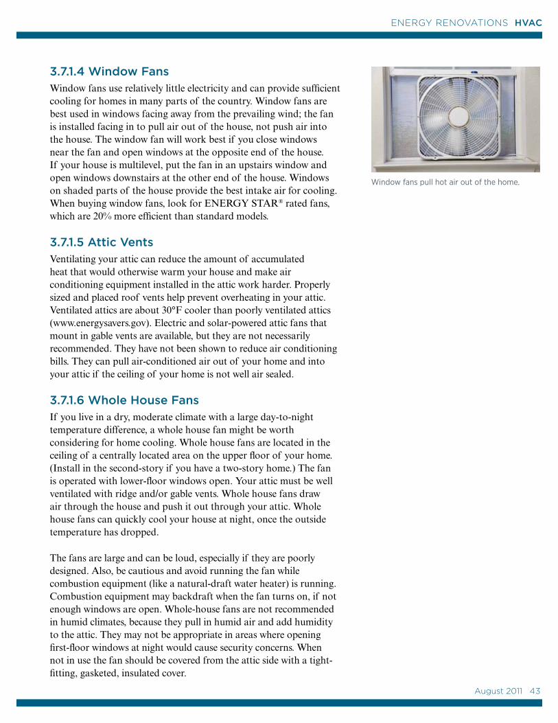
3.7.1.4 Window Fans Window fans use relatively little electricity and can provide sufficient cooling for homes in many parts of the country. Window fans are best used in windows facing away from the prevailing wind; the fan is installed facing in to pull air out of the house, not push air into the house. The window fan will work best if you close windows near the fan and open windows at the opposite end of the house. If your house is multilevel, put the fan in an upstairs window and open windows downstairs at the other end of the house. Windows on shaded parts of the house provide the best intake air for cooling. When buying window fans, look for ENERGY STAR® rated fans, which are 20% more efficient than standard models.
3.7.1.5 Attic Vents Ventilating your attic can reduce the amount of accumulated heat that would otherwise warm your house and make air conditioning equipment installed in the attic work harder. Properly sized and placed roof vents help prevent overheating in your attic. Ventilated attics are about 30°F cooler than poorly ventilated attics (www.energysavers.gov). Electric and solar-powered attic fans that mount in gable vents are available, but they are not necessarily recommended. They have not been shown to reduce air conditioning bills. They can pull air-conditioned air out of your home and into your attic if the ceiling of your home is not well air sealed.
3.7.1.6 Whole House FansIf you live in a dry, moderate climate with a large day-to-night temperature difference, a whole house fan might be worth considering for home cooling. Whole house fans are located in the ceiling of a centrally located area on the upper floor of your home. (Install in the second-story if you have a two-story home.) The fan is operated with lower-floor windows open. Your attic must be well ventilated with ridge and/or gable vents. Whole house fans draw air through the house and push it out through your attic. Whole house fans can quickly cool your house at night, once the outside temperature has dropped.
The fans are large and can be loud, especially if they are poorly designed. Also, be cautious and avoid running the fan while combustion equipment (like a natural-draft water heater) is running. Combustion equipment may backdraft when the fan turns on, if not enough windows are open. Whole-house fans are not recommended in humid climates, because they pull in humid air and add humidity to the attic. They may not be appropriate in areas where opening first-floor windows at night would cause security concerns. When not in use the fan should be covered from the attic side with a tight-fitting, gasketed, insulated cover.
Window fans pull hot air out of the home.
August 2011 43
43
ENERGY RENOVATIONS HVAC
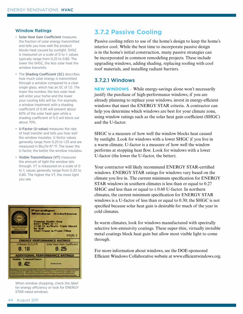
3.7.2 Passive Cooling Passive cooling refers to use of the home’s design to keep the home’s interior cool. While the best time to incorporate passive design is in the home’s initial construction, many passive strategies can be incorporated in common remodeling projects. These include upgrading windows, adding shading, replacing roofing with cool roof materials, and installing radiant barriers.
3.7.2.1 Windows
NEW WINDOWS – While energy-savings alone won’t necessarily justify the purchase of high-performance windows, if you are already planning to replace your windows, invest in energy-efficient windows that meet the ENERGY STAR criteria. A contractor can help you determine which windows are best for your climate zone, using window ratings such as the solar heat gain coefficient (SHGC) and the U-factor.
SHGC is a measure of how well the window blocks heat caused by sunlight. Look for windows with a lower SHGC if you live in a warm climate. U-factor is a measure of how well the window performs at stopping heat flow. Look for windows with a lower U-factor (the lower the U-factor, the better).
Your contractor will likely recommend ENERGY STAR-certified windows. ENERGY STAR ratings for windows vary based on the climate you live in. The current minimum specification for ENERGY STAR windows in southern climates is less than or equal to 0.27 SHGC and less than or equal to ≤ 0.60 U-factor. In northern climates, the current minimum specification for ENERGY STAR windows is a U-factor of less than or equal to 0.30; the SHGC is not specified because solar heat gain is desirable for much of the year in cold climates.
In warm climates, look for windows manufactured with spectrally selective low-emissivity coatings. These super-thin, virtually invisible metal coatings block heat gain but allow most visible light to come through.
For more information about windows, see the DOE-sponsored Efficient Windows Collaborative website at www.efficientwindows.org.
When window shopping, check the label for energy efficiency or look for ENERGY STAR-rated windows.
Window Ratings
• Solar Heat Gain Coefficient measures the fraction of solar energy transmitted and tells you how well the product blocks heat caused by sunlight. SHGC is measured on a scale of 0 to 1; values typically range from 0.25 to 0.80. The lower the SHGC, the less solar heat the window transmits.
• The Shading Coefficient (SC) describes how much solar energy is transmitted through a window compared to a clear single glass, which has an SC of 1.0. The lower the number, the less solar heat will enter your home and the lower your cooling bills will be. For example, a window treatment with a shading coefficient of 0.40 will prevent about 60% of the solar heat gain while a shading coefficient of 0.3 will block out about 70%.
• U-Factor (U-value) measures the rate of heat transfer and tells you how well the window insulates. U-factor values generally range from 0.25 to 1.25 and are measured in Btu/hr·ft²·°F. The lower the U-factor, the better the window insulates.
• Visible Transmittance (VT) measures the amount of light the window lets through. VT is measured on a scale of 0 to 1; values generally range from 0.20 to 0.80. The higher the VT, the more light you see.
44 August 2011
ENERGY RENOVATIONS HVAC

EXISTING WINDOWS – If you are keeping your existing windows, there are some steps you can take to reduce how much heat they let in. On south- and west-facing windows, you can install sun screens that have small aluminum louvers, fiberglass mesh, or tough metalized polyester film laminated to vinyl. Such removable shade screens can be taken down to allow you to take advantage of the sun’s heat during the winter.
You can also reduce heat from the sun by applying window-tinting films. One problem with these films is that they can reduce the clarity of the glass; they may also need to be reapplied. However, such treatments and shades are much less expensive than new windows.
3.7.2.2 Shading According to the U.S. Department of Housing and Urban Development, stopping the sun’s heat before it penetrates windows and sliding glass doors is up to seven times more effective than using interior blinds or curtains (APS 2009).
Exterior shading options include trees, porches, awnings, pergolas, trellises, working shutters. If your remodeling project includes changing the roofline, include overhangs in your design, especially on south-facing walls. Overhangs protect windows and walls from heat gain and ultraviolet radiation, as well as rain, hail, and snow. Optimal overhang dimensions for blocking summer sun while allowing winter sun to come in can be calculated at www.susdesign.com/overhang/index.php.
Mature, well-placed trees can reduce cooling costs by 5% to 10%.
Careful landscaping can preserve roof-top solar exposure for solar panels and provide shading to help control solar heat gain through windows. Large deciduous shade trees on the southwest corner of the home provide welcome relief from summer afternoon sun while allowing desirable winter sun to warm the house (Walker and Newman 2009).
August 2011 45
45
ENERGY RENOVATIONS HVAC
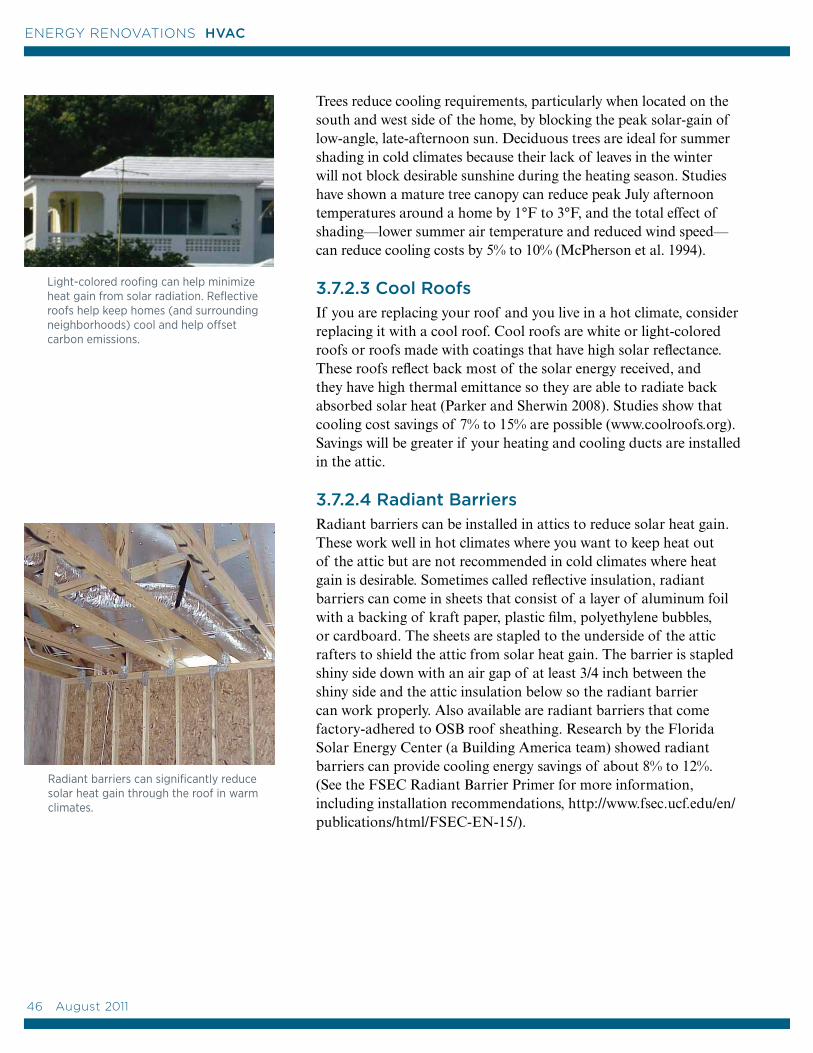
Trees reduce cooling requirements, particularly when located on the south and west side of the home, by blocking the peak solar-gain of low-angle, late-afternoon sun. Deciduous trees are ideal for summer shading in cold climates because their lack of leaves in the winter will not block desirable sunshine during the heating season. Studies have shown a mature tree canopy can reduce peak July afternoon temperatures around a home by 1°F to 3°F, and the total effect of shading—lower summer air temperature and reduced wind speed—can reduce cooling costs by 5% to 10% (McPherson et al. 1994).
3.7.2.3 Cool RoofsIf you are replacing your roof and you live in a hot climate, consider replacing it with a cool roof. Cool roofs are white or light-colored roofs or roofs made with coatings that have high solar reflectance. These roofs reflect back most of the solar energy received, and they have high thermal emittance so they are able to radiate back absorbed solar heat (Parker and Sherwin 2008). Studies show that cooling cost savings of 7% to 15% are possible (www.coolroofs.org). Savings will be greater if your heating and cooling ducts are installed in the attic.
3.7.2.4 Radiant BarriersRadiant barriers can be installed in attics to reduce solar heat gain. These work well in hot climates where you want to keep heat out of the attic but are not recommended in cold climates where heat gain is desirable. Sometimes called reflective insulation, radiant barriers can come in sheets that consist of a layer of aluminum foil with a backing of kraft paper, plastic film, polyethylene bubbles, or cardboard. The sheets are stapled to the underside of the attic rafters to shield the attic from solar heat gain. The barrier is stapled shiny side down with an air gap of at least 3/4 inch between the shiny side and the attic insulation below so the radiant barrier can work properly. Also available are radiant barriers that come factory-adhered to OSB roof sheathing. Research by the Florida Solar Energy Center (a Building America team) showed radiant barriers can provide cooling energy savings of about 8% to 12%. (See the FSEC Radiant Barrier Primer for more information, including installation recommendations, http://www.fsec.ucf.edu/en/publications/html/FSEC-EN-15/).
Light-colored roofing can help minimize heat gain from solar radiation. Reflective roofs help keep homes (and surrounding neighborhoods) cool and help offset carbon emissions.
Radiant barriers can significantly reduce solar heat gain through the roof in warm climates.
46 August 2011
ENERGY RENOVATIONS HVAC
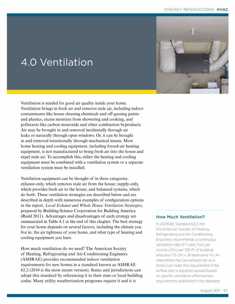
4.0 Ventilation
Ventilation is needed for good air quality inside your home. Ventilation brings in fresh air and removes stale air, including indoor contaminants like house cleaning chemicals and off-gassing paints and plastics, excess moisture from showering and cooking, and pollutants like carbon monoxide and other combustion byproducts. Air may be brought in and removed incidentally through air leaks or naturally through open windows. Or, it can be brought in and removed intentionally through mechanical means. Most home heating and cooling equipment, including forced-air heating equipment, is not manufactured to bring fresh air into the house and expel stale air. To accomplish this, either the heating and cooling equipment must be combined with a ventilation system or a separate ventilation system must be installed.
Ventilation equipment can be thought of in three categories: exhaust-only, which removes stale air from the house; supply-only, which provides fresh air to the house; and balanced systems, which do both. These ventilation strategies are described below and are described in depth with numerous examples of configuration options in the report, Local Exhaust and Whole House Ventilation Strategies, prepared by Building Science Corporation for Building America (Rudd 2011). Advantages and disadvantages of each strategy are summarized in Table 4.1 at the end of this chapter. The best strategy for your home depends on several factors, including the climate you live in, the air tightness of your home, and what type of heating and cooling equipment you have.
How much ventilation do we need? The American Society of Heating, Refrigerating and Air-Conditioning Engineers (ASHRAE) provides recommended indoor ventilation requirements for new homes in a standard known as ASHRAE 62.2 (2010 is the most recent version). States and jurisdictions can adopt this standard by referencing it in their state or local building codes. Many utility weatherization programs require it and it is
How Much Ventilation?
In ASHRAE Standard 62.2, the the American Society of Heating, Refrigerating and Air-Conditioning Engineers recommends a continuous ventilation rate of 1 cubic foot per minute (cfm) per 100 ft2 of building area plus 7.5 cfm x (# bedrooms +1). An intermittent fan (an exhaust fan on a timer) can meet this requirement if the airflow rate is adjusted upward based on specific ventilation effectiveness requirements published in the standard.
August 2011 47
47
ENERGY RENOVATIONS HVAC
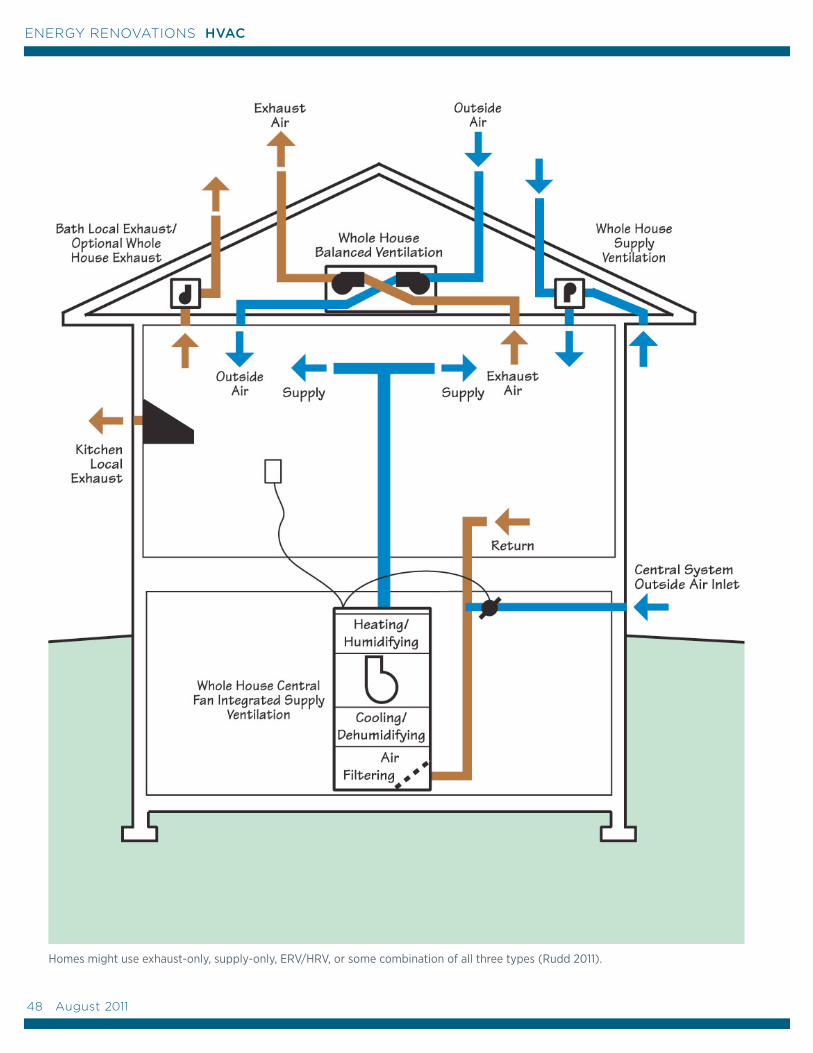
Homes might use exhaust-only, supply-only, ERV/HRV, or some combination of all three types (Rudd 2011).
48 August 2011
ENERGY RENOVATIONS HVAC
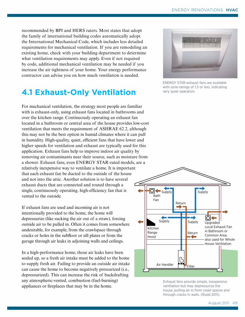
KitchenRange Hood
Bath Fan
Supply
Return
Air Handler
Supply
Supply Supply
Return
Filter
Upgraded Local Exhaust Fan in Bathroom or Common Area; also used for Whole House Ventilation
recommended by BPI and HERS raters. Most states that adopt the family of international building codes automatically adopt the International Mechanical Code, which includes less detailed requirements for mechanical ventilation. If you are remodeling an existing home, check with your building department to determine what ventilation requirements may apply. Even if not required by code, additional mechanical ventilation may be needed if you increase the air tightness of your home. Your energy performance contractor can advise you on how much ventilation is needed.
4.1 Exhaust-Only Ventilation
For mechanical ventilation, the strategy most people are familiar with is exhaust-only, using exhaust fans located in bathrooms and over the kitchen range. Continuously operating an exhaust fan located in a bathroom or central area of the house provides low-cost ventilation that meets the requirement of ASHRAE 62.2, although this may not be the best option in humid climates where it can pull in humidity. High-quality, quiet, efficient fans that have lower and higher speeds for ventilation and exhaust are typically used for this application. Exhaust fans help to improve indoor air quality by removing air contaminants near their source, such as moisture from a shower. Exhaust fans, even ENERGY STAR-rated models, are a relatively inexpensive way to ventilate a home. It is important that each exhaust fan be ducted to the outside of the house and not into the attic. Another solution is to have several exhaust ducts that are connected and routed through a single, continuously operating, high-efficiency fan that is vented to the outside.
If exhaust fans are used and incoming air is not intentionally provided to the home, the home will depressurize (like sucking the air out of a straw), forcing outside air to be pulled in. Often it comes from somewhere undesirable, for example, from the crawlspace through cracks or holes in the subfloor or sill plates or from the garage through air leaks in adjoining walls and ceilings.
In a high-performance home, those air leaks have been sealed up, so a fresh air intake must be added to the home to supply fresh air. Failing to provide an outside air intake can cause the home to become negatively pressurized (i.e., depressurized). This can increase the risk of backdrafting any atmospheric-vented, combustion (fuel-burning) appliances or fireplaces that may be in the home.
ENERGY STAR exhaust fans are available with sone ratings of 1.5 or less, indicating very quiet operation.
Exhaust fans provide simple, inexpensive ventilation but may depressurize the house, pulling air in from crawl spaces and through cracks in walls. (Rudd 2011).
August 2011 49
49
ENERGY RENOVATIONS HVAC
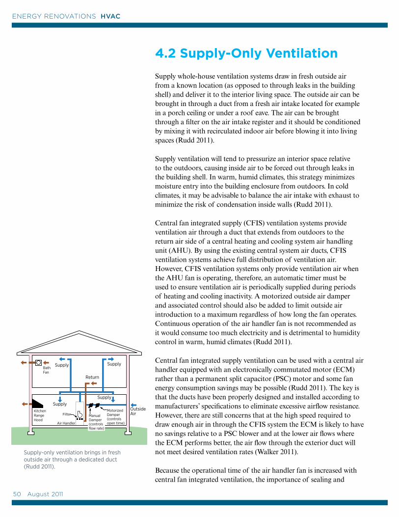
4.2 Supply-Only Ventilation
Supply whole-house ventilation systems draw in fresh outside air from a known location (as opposed to through leaks in the building shell) and deliver it to the interior living space. The outside air can be brought in through a duct from a fresh air intake located for example in a porch ceiling or under a roof eave. The air can be brought through a filter on the air intake register and it should be conditioned by mixing it with recirculated indoor air before blowing it into living spaces (Rudd 2011).
Supply ventilation will tend to pressurize an interior space relative to the outdoors, causing inside air to be forced out through leaks in the building shell. In warm, humid climates, this strategy minimizes moisture entry into the building enclosure from outdoors. In cold climates, it may be advisable to balance the air intake with exhaust to minimize the risk of condensation inside walls (Rudd 2011).
Central fan integrated supply (CFIS) ventilation systems provide ventilation air through a duct that extends from outdoors to the return air side of a central heating and cooling system air handling unit (AHU). By using the existing central system air ducts, CFIS ventilation systems achieve full distribution of ventilation air. However, CFIS ventilation systems only provide ventilation air when the AHU fan is operating, therefore, an automatic timer must be used to ensure ventilation air is periodically supplied during periods of heating and cooling inactivity. A motorized outside air damper and associated control should also be added to limit outside air introduction to a maximum regardless of how long the fan operates. Continuous operation of the air handler fan is not recommended as it would consume too much electricity and is detrimental to humidity control in warm, humid climates (Rudd 2011).
Central fan integrated supply ventilation can be used with a central air handler equipped with an electronically commutated motor (ECM) rather than a permanent split capacitor (PSC) motor and some fan energy consumption savings may be possible (Rudd 2011). The key is that the ducts have been properly designed and installed according to manufacturers’ specifications to eliminate excessive airflow resistance. However, there are still concerns that at the high speed required to draw enough air in through the CFIS system the ECM is likely to have no savings relative to a PSC blower and at the lower air flows where the ECM performs better, the air flow through the exterior duct will not meet desired ventilation rates (Walker 2011).
Because the operational time of the air handler fan is increased with central fan integrated ventilation, the importance of sealing and
Supply-only ventilation brings in fresh outside air through a dedicated duct (Rudd 2011).
Air Handler
Outside Air
SupplySupply
Supply
KitchenRange Hood
Bath Fan
Return
Filter ManualDamper(controlsflow rate)
Motorized Damper(controlsopen time)
Supply
50 August 2011
ENERGY RENOVATIONS HVAC
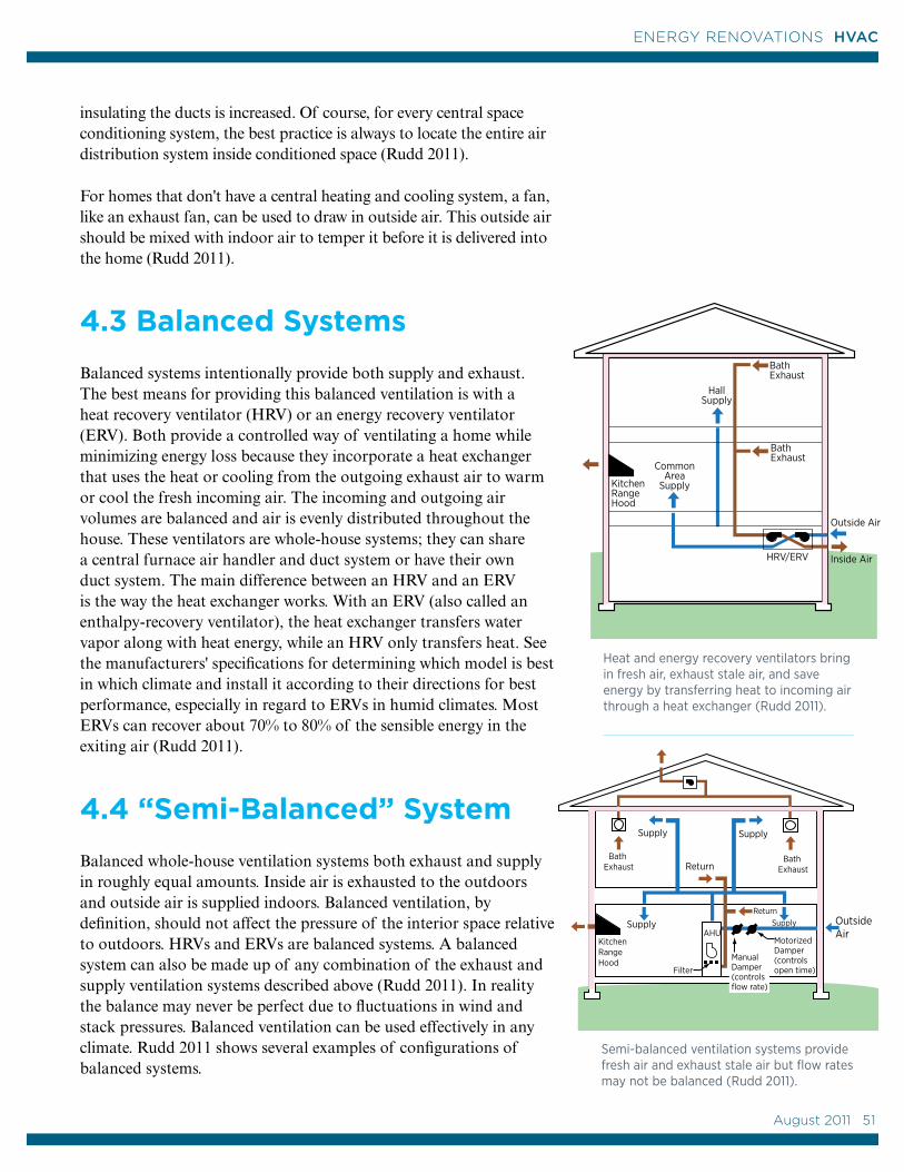
KitchenRange Hood
Bath Exhaust
HRV/ERV
HallSupply
Outside Air
CommonArea
Supply
Bath Exhaust
Inside Air
insulating the ducts is increased. Of course, for every central space conditioning system, the best practice is always to locate the entire air distribution system inside conditioned space (Rudd 2011).
For homes that don't have a central heating and cooling system, a fan, like an exhaust fan, can be used to draw in outside air. This outside air should be mixed with indoor air to temper it before it is delivered into the home (Rudd 2011).
4.3 Balanced Systems
Balanced systems intentionally provide both supply and exhaust. The best means for providing this balanced ventilation is with a heat recovery ventilator (HRV) or an energy recovery ventilator (ERV). Both provide a controlled way of ventilating a home while minimizing energy loss because they incorporate a heat exchanger that uses the heat or cooling from the outgoing exhaust air to warm or cool the fresh incoming air. The incoming and outgoing air volumes are balanced and air is evenly distributed throughout the house. These ventilators are whole-house systems; they can share a central furnace air handler and duct system or have their own duct system. The main difference between an HRV and an ERV is the way the heat exchanger works. With an ERV (also called an enthalpy-recovery ventilator), the heat exchanger transfers water vapor along with heat energy, while an HRV only transfers heat. See the manufacturers' specifications for determining which model is best in which climate and install it according to their directions for best performance, especially in regard to ERVs in humid climates. Most ERVs can recover about 70% to 80% of the sensible energy in the exiting air (Rudd 2011).
4.4 “Semi-Balanced” System
Balanced whole-house ventilation systems both exhaust and supply in roughly equal amounts. Inside air is exhausted to the outdoors and outside air is supplied indoors. Balanced ventilation, by definition, should not affect the pressure of the interior space relative to outdoors. HRVs and ERVs are balanced systems. A balanced system can also be made up of any combination of the exhaust and supply ventilation systems described above (Rudd 2011). In reality the balance may never be perfect due to fluctuations in wind and stack pressures. Balanced ventilation can be used effectively in any climate. Rudd 2011 shows several examples of configurations of balanced systems.
Semi-balanced ventilation systems provide fresh air and exhaust stale air but flow rates may not be balanced (Rudd 2011).
Outside Air
Supply Supply
ManualDamper(controlsflow rate)
Motorized Damper(controlsopen time)
KitchenRange Hood
Bath Exhaust Return
Filter
Bath Exhaust
SupplyReturn
SupplyAHU
Heat and energy recovery ventilators bring in fresh air, exhaust stale air, and save energy by transferring heat to incoming air through a heat exchanger (Rudd 2011).
August 2011 51
51
ENERGY RENOVATIONS HVAC
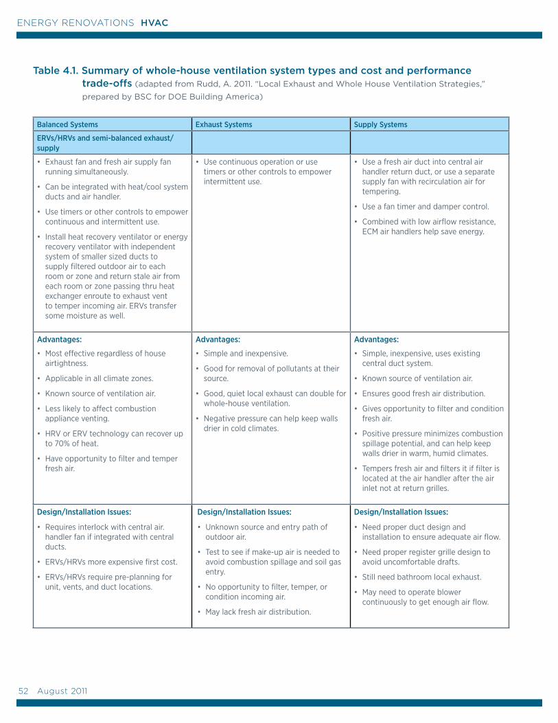
Table 4.1. Summary of whole-house ventilation system types and cost and performance trade-offs (adapted from Rudd, A. 2011. “Local Exhaust and Whole House Ventilation Strategies,”
prepared by BSC for DOE Building America)
Balanced Systems Exhaust Systems Supply Systems
ERVs/HRVs and semi-balanced exhaust/supply
• Exhaust fan and fresh air supply fan running simultaneously.
• Can be integrated with heat/cool system ducts and air handler.
• Use timers or other controls to empower continuous and intermittent use.
• Install heat recovery ventilator or energy recovery ventilator with independent system of smaller sized ducts to supply filtered outdoor air to each room or zone and return stale air from each room or zone passing thru heat exchanger enroute to exhaust vent to temper incoming air. ERVs transfer some moisture as well.
• Use continuous operation or use timers or other controls to empower intermittent use.
• Use a fresh air duct into central air handler return duct, or use a separate supply fan with recirculation air for tempering.
• Use a fan timer and damper control.
• Combined with low airflow resistance, ECM air handlers help save energy.
Advantages:
• Most effective regardless of house airtightness.
• Applicable in all climate zones.
• Known source of ventilation air.
• Less likely to affect combustion appliance venting.
• HRV or ERV technology can recover up to 70% of heat.
• Have opportunity to filter and temper fresh air.
Advantages:
• Simple and inexpensive.
• Good for removal of pollutants at their source.
• Good, quiet local exhaust can double for whole-house ventilation.
• Negative pressure can help keep walls drier in cold climates.
Advantages:
• Simple, inexpensive, uses existing central duct system.
• Known source of ventilation air.
• Ensures good fresh air distribution.
• Gives opportunity to filter and condition fresh air.
• Positive pressure minimizes combustion spillage potential, and can help keep walls drier in warm, humid climates.
• Tempers fresh air and filters it if filter is located at the air handler after the air inlet not at return grilles.
Design/Installation Issues:
• Requires interlock with central air. handler fan if integrated with central ducts.
• ERVs/HRVs more expensive first cost.
• ERVs/HRVs require pre-planning for unit, vents, and duct locations.
Design/Installation Issues:
• Unknown source and entry path of outdoor air.
• Test to see if make-up air is needed to avoid combustion spillage and soil gas entry.
• No opportunity to filter, temper, or condition incoming air.
• May lack fresh air distribution.
Design/Installation Issues:
• Need proper duct design and installation to ensure adequate air flow.
• Need proper register grille design to avoid uncomfortable drafts.
• Still need bathroom local exhaust.
• May need to operate blower continuously to get enough air flow.
52 August 2011
ENERGY RENOVATIONS HVAC
The U.S. Department of Energy Office of Renewable Energy and Energy Efficiency (DOE-EERE) and the U.S. Environmental Protection Agency are committed to a whole-house approach to energy upgrading a home to ensure homeowner health and safety as well as cost-effective energy savings. This approach is based on an understanding that every system in the home interacts with the other systems in the home. Thus, changes to the home's heating, ventilating, and cooling equipment can have health and safety consequences that must be taken into account. A home energy performance assessment, conducted by trained contractors, following recognized guidelines such as DOE’s Workforce Guidelines for Home Energy Upgrades, will take into account these interactions and help homeowners identify and implement safe, effective energy improvements.
Homeowners should have a home energy performance assessment done when adding or replacing HVAC equipment, when they want to improve their home's efficiency by air sealing or adding new insulation, or when they are planning a major remodelling project.
5.1 Certified Energy Contractors
A Building America-approved home energy assessment is conducted by a contractor who is trained and certified in building science principles and follows a prescribed approach to ensure the safest and most efficient ways to improve your home’s energy efficiency.
There are two nationally recognized energy certifications for home performance energy contractors: the Building Performance Institute (BPI) Building Analyst certification and the Residential Energy Services Network (RESNET) HERS Rater certification. Historically,
Building Performance Institute -The BPI is a nonprofit organization that accredits auditors, contractors, and other building professionals. Auditors or building analysts specialize in evaluating building systems and potential energy savings in homes. The certified BPI Building Analyst energy auditor has passed both written and field exams, and must recertify every three years. Contractors learn about building systems and are trained to perform energy efficiency assessments and conduct combustion safety testing. For more information see www.BPI.org
A certified Residential Energy Services Network (RESNET) energy auditor is called a HERS rater. HERS raters are certified to provide homes with a HERS (the Home Energy Rating System) score, which provides a miles-per-gallon type rating of expected energy consumption that makes it easy to compare the energy performance of one home to another. More information about HERS can be found at www.resnet.us.
5.0 The Home Performance Energy Assessment
August 2011 53
53
ENERGY RENOVATIONS HVAC
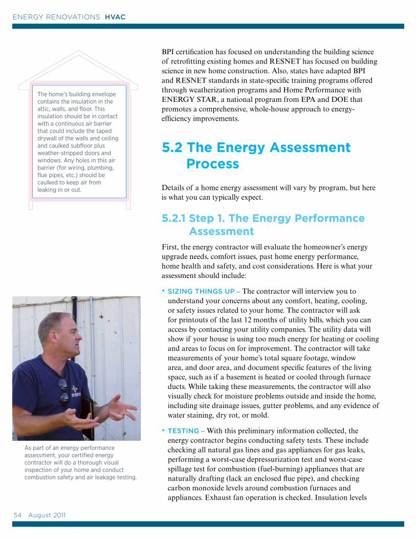
BPI certification has focused on understanding the building science of retrofitting existing homes and RESNET has focused on building science in new home construction. Also, states have adapted BPI and RESNET standards in state-specific training programs offered through weatherization programs and Home Performance with ENERGY STAR, a national program from EPA and DOE that promotes a comprehensive, whole-house approach to energy-efficiency improvements.
5.2 The Energy Assessment Process
Details of a home energy assessment will vary by program, but here is what you can typically expect.
5.2.1 Step 1. The Energy Performance Assessment First, the energy contractor will evaluate the homeowner’s energy upgrade needs, comfort issues, past home energy performance, home health and safety, and cost considerations. Here is what your assessment should include:
• SIZING THINGS UP – The contractor will interview you to understand your concerns about any comfort, heating, cooling, or safety issues related to your home. The contractor will ask for printouts of the last 12 months of utility bills, which you can access by contacting your utility companies. The utility data will show if your house is using too much energy for heating or cooling and areas to focus on for improvement. The contractor will take measurements of your home’s total square footage, window area, and door area, and document specific features of the living space, such as if a basement is heated or cooled through furnace ducts. While taking these measurements, the contractor will also visually check for moisture problems outside and inside the home, including site drainage issues, gutter problems, and any evidence of water staining, dry rot, or mold.
• TESTING – With this preliminary information collected, the energy contractor begins conducting safety tests. These include checking all natural gas lines and gas appliances for gas leaks, performing a worst-case depressurization test and worst-case spillage test for combustion (fuel-burning) appliances that are naturally drafting (lack an enclosed flue pipe), and checking carbon monoxide levels around combustion furnaces and appliances. Exhaust fan operation is checked. Insulation levels
pink = insulation blue = air barrier
As part of an energy performance assessment, your certified energy contractor will do a thorough visual inspection of your home and conduct combustion safety and air leakage testing.
The home’s building envelope contains the insulation in the attic, walls, and floor. This insulation should be in contact with a continuous air barrier that could include the taped drywall of the walls and ceiling and caulked subfloor plus weather-stripped doors and windows. Any holes in this air barrier (for wiring, plumbing, flue pipes, etc.) should be caulked to keep air from leaking in or out.
54 August 2011
ENERGY RENOVATIONS HVAC
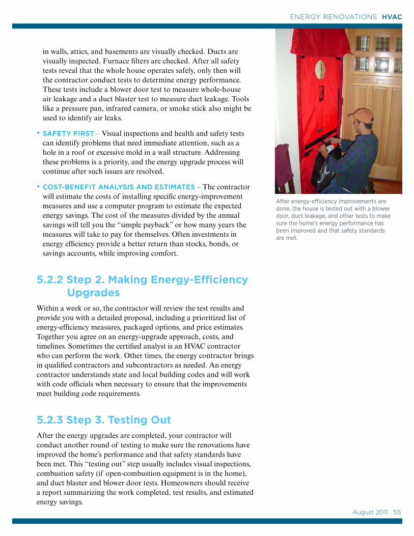
in walls, attics, and basements are visually checked. Ducts are visually inspected. Furnace filters are checked. After all safety tests reveal that the whole house operates safely, only then will the contractor conduct tests to determine energy performance. These tests include a blower door test to measure whole-house air leakage and a duct blaster test to measure duct leakage. Tools like a pressure pan, infrared camera, or smoke stick also might be used to identify air leaks.
• SAFETY FIRST – Visual inspections and health and safety tests can identify problems that need immediate attention, such as a hole in a roof or excessive mold in a wall structure. Addressing these problems is a priority, and the energy upgrade process will continue after such issues are resolved.
• COST-BENEFIT ANALYSIS AND ESTIMATES – The contractor will estimate the costs of installing specific energy-improvement measures and use a computer program to estimate the expected energy savings. The cost of the measures divided by the annual savings will tell you the “simple payback” or how many years the measures will take to pay for themselves. Often investments in energy efficiency provide a better return than stocks, bonds, or savings accounts, while improving comfort.
5.2.2 Step 2. Making Energy-Efficiency UpgradesWithin a week or so, the contractor will review the test results and provide you with a detailed proposal, including a prioritized list of energy-efficiency measures, packaged options, and price estimates. Together you agree on an energy-upgrade approach, costs, and timelines. Sometimes the certified analyst is an HVAC contractor who can perform the work. Other times, the energy contractor brings in qualified contractors and subcontractors as needed. An energy contractor understands state and local building codes and will work with code officials when necessary to ensure that the improvements meet building code requirements.
5.2.3 Step 3. Testing OutAfter the energy upgrades are completed, your contractor will conduct another round of testing to make sure the renovations have improved the home’s performance and that safety standards have been met. This “testing out” step usually includes visual inspections, combustion safety (if open-combustion equipment is in the home), and duct blaster and blower door tests. Homeowners should receive a report summarizing the work completed, test results, and estimated energy savings.
After energy-efficiency improvements are done, the house is tested out with a blower door, duct leakage, and other tests to make sure the home’s energy performance has been improved and that safety standards are met.
August 2011 55
55
ENERGY RENOVATIONS HVAC
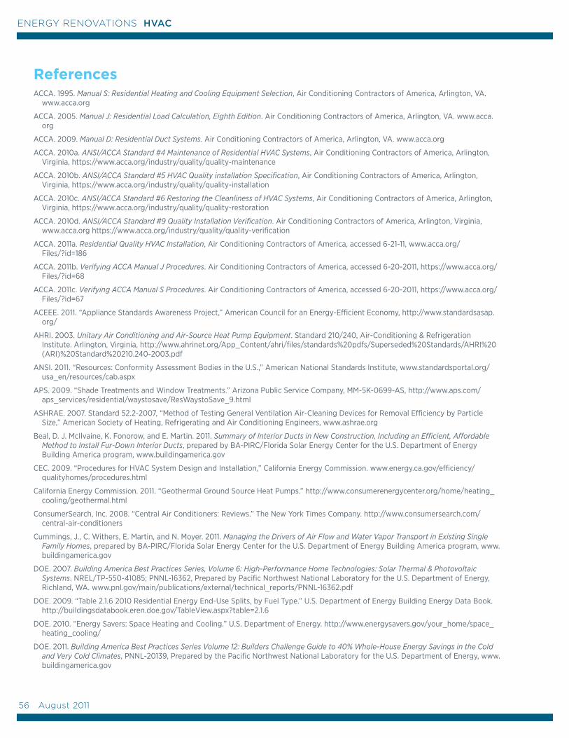
ReferencesACCA. 1995. Manual S: Residential Heating and Cooling Equipment Selection, Air Conditioning Contractors of America, Arlington, VA.
www.acca.org
ACCA. 2005. Manual J: Residential Load Calculation, Eighth Edition. Air Conditioning Contractors of America, Arlington, VA. www.acca.org
ACCA. 2009. Manual D: Residential Duct Systems. Air Conditioning Contractors of America, Arlington, VA. www.acca.org
ACCA. 2010a. ANSI/ACCA Standard #4 Maintenance of Residential HVAC Systems, Air Conditioning Contractors of America, Arlington, Virginia, https://www.acca.org/industry/quality/quality-maintenance
ACCA. 2010b. ANSI/ACCA Standard #5 HVAC Quality installation Specification, Air Conditioning Contractors of America, Arlington, Virginia, https://www.acca.org/industry/quality/quality-installation
ACCA. 2010c. ANSI/ACCA Standard #6 Restoring the Cleanliness of HVAC Systems, Air Conditioning Contractors of America, Arlington, Virginia, https://www.acca.org/industry/quality/quality-restoration
ACCA. 2010d. ANSI/ACCA Standard #9 Quality Installation Verification. Air Conditioning Contractors of America, Arlington, Virginia, www.acca.org https://www.acca.org/industry/quality/quality-verification
ACCA. 2011a. Residential Quality HVAC Installation, Air Conditioning Contractors of America, accessed 6-21-11, www.acca.org/ Files/?id=186
ACCA. 2011b. Verifying ACCA Manual J Procedures. Air Conditioning Contractors of America, accessed 6-20-2011, https://www.acca.org/Files/?id=68
ACCA. 2011c. Verifying ACCA Manual S Procedures. Air Conditioning Contractors of America, accessed 6-20-2011, https://www.acca.org/Files/?id=67
ACEEE. 2011. “Appliance Standards Awareness Project,” American Council for an Energy-Efficient Economy, http://www.standardsasap.org/
AHRI. 2003. Unitary Air Conditioning and Air-Source Heat Pump Equipment. Standard 210/240, Air-Conditioning & Refrigeration Institute. Arlington, Virginia, http://www.ahrinet.org/App_Content/ahri/files/standards%20pdfs/Superseded%20Standards/AHRI%20(ARI)%20Standard%20210.240-2003.pdf
ANSI. 2011. “Resources: Conformity Assessment Bodies in the U.S.,” American National Standards Institute, www.standardsportal.org/usa_en/resources/cab.aspx
APS. 2009. “Shade Treatments and Window Treatments.” Arizona Public Service Company, MM-5K-0699-AS, http://www.aps.com/aps_services/residential/waystosave/ResWaystoSave_9.html
ASHRAE. 2007. Standard 52.2-2007, “Method of Testing General Ventilation Air-Cleaning Devices for Removal Efficiency by Particle Size,” American Society of Heating, Refrigerating and Air Conditioning Engineers, www.ashrae.org
Beal, D. J. McIlvaine, K. Fonorow, and E. Martin. 2011. Summary of Interior Ducts in New Construction, Including an Efficient, Affordable Method to Install Fur-Down Interior Ducts, prepared by BA-PIRC/Florida Solar Energy Center for the U.S. Department of Energy Building America program, www.buildingamerica.gov
CEC. 2009. “Procedures for HVAC System Design and Installation,” California Energy Commission. www.energy.ca.gov/efficiency/qualityhomes/procedures.html
California Energy Commission. 2011. “Geothermal Ground Source Heat Pumps.” http://www.consumerenergycenter.org/home/heating_cooling/geothermal.html
ConsumerSearch, Inc. 2008. “Central Air Conditioners: Reviews.” The New York Times Company. http://www.consumersearch.com/central-air-conditioners
Cummings, J., C. Withers, E. Martin, and N. Moyer. 2011. Managing the Drivers of Air Flow and Water Vapor Transport in Existing Single Family Homes, prepared by BA-PIRC/Florida Solar Energy Center for the U.S. Department of Energy Building America program, www.buildingamerica.gov
DOE. 2007. Building America Best Practices Series, Volume 6: High-Performance Home Technologies: Solar Thermal & Photovoltaic Systems. NREL/TP-550-41085; PNNL-16362, Prepared by Pacific Northwest National Laboratory for the U.S. Department of Energy, Richland, WA. www.pnl.gov/main/publications/external/technical_reports/PNNL-16362.pdf
DOE. 2009. “Table 2.1.6 2010 Residential Energy End-Use Splits, by Fuel Type.” U.S. Department of Energy Building Energy Data Book. http://buildingsdatabook.eren.doe.gov/TableView.aspx?table=2.1.6
DOE. 2010. “Energy Savers: Space Heating and Cooling.” U.S. Department of Energy. http://www.energysavers.gov/your_home/space_heating_cooling/
DOE. 2011. Building America Best Practices Series Volume 12: Builders Challenge Guide to 40% Whole-House Energy Savings in the Cold and Very Cold Climates, PNNL-20139, Prepared by the Pacific Northwest National Laboratory for the U.S. Department of Energy, www.buildingamerica.gov
56 August 2011
ENERGY RENOVATIONS HVAC
Eastment, M., E. Hancock, and C. Kutscher. 2005. Projected Costs and Benefits of New Residential Evaporative Cooling Systems, Golden, CO: National Renewable Energy Laboratory. www.nrel.gov/docs/fy07osti/39342.pdf
EIA. 2005. “Residential Energy Consumption Survey: Preliminary Housing Characteristics Tables,” U.S. Energy Information Administration, http://www.eia.doe.gov/emeu/recs/
EIA. 2010. “Geothermal Heat Pump,” U.S. Energy Information Administration. http://www.eia.gov/cneaf/solar.renewables/page/heatpumps/heatpumps.html
EIA. 2008. “Average Expenditures for Air-Conditioning by Equipment Type, 2005,” U.S. Energy Information Administration. http://www.eia.doe.gov/emeu/recs/recs2005/c&e/airconditioning/excel/tableac7.xls
Farzad, M. and D.L. O’Neal. 1998. An Evaluation of Improper Refrigerant Charge on the Performance of a Split System Air Conditioner with Capillary Tube Expansion, Prepared for the Energy Systems Laboratory Research Consortium, Texas A&M University. ESLTR-88/07-01. http://repository.tamu.edu/bitstream/handle/1969.1/2041/ESL-TR-88-07-01.pdf?sequence=1
Henkenius, Merle. 1998. “Geothermal Heating,” Popular Mechanics, Oct 1, 1998, http://www.popularmechanics.com/home/improvement/energy-efficient/1274631
IECC. 2009. International Energy Conservation Code, International Code Council (ICC), Washington, D.C. www.iccsafe.org/Store/Pages
Karr, M. 2011. “Ground-Source Variable Refrigerant Flow Heat Pumps,” Washington State University Extension Energy Program, www.energy.wsu.edu/Documents/EEFactsheet-GSHP-Feb2011.pdf
Krigger, John and Chris Dorsi. 2009. Residential Energy: Cost Savings and Comfort for Existing Buildings, 5th Edition, Saturn Resource Management, http://srmi.biz/Bookstore.Professionals.Residential_Energy.htm
LBNL. 2011. “Energy Efficiency Standards,” Lawrence Berkeley National Laboratory, accessed 2011. http://ees.ead.lbl.gov/taxonomy/term/1
McPherson, G.E., D.J. Nowak, and R.A. Rowntree (eds). 1994. Chicago’s Urban Forest Ecosystem: Results of the Chicago Urban Forest Climate Project. U.S. Department of Agriculture, Forest Service, Northeastern Research Station.
McWilliams, J.A., I.S. Walker 2005. Renovating Residential HVAC Systems, Lawrence Berkeley National Laboratory. LBNL 57406. http://epb.lbl.gov/publications/lbnl-57406.pdf
Northwest Energy Efficiency Alliance. 2009. “Ductless Heat Pump Project,” NEEA, http://www.nwductless.com/
NRCan. 2009. “Personal: Residential Air-Source Heat Pumps,” Natural Resources Canada, http://oee.nrcan.gc.ca/publications/infosource/pub/home/heating-heat-pump/asheatpumps.cfm
Parker, D., J. Sherwin. 2008. Experimental Evaluation of the NightCool Nocturnal Radiation Cooling Concept: Annual Performance Assessment in Scale Test Buildings, Florida Solar Energy Center, http://securedb.fsec.ucf.edu/pub/pub_show_detail?v_pub_id=4389
Rudd, Armin, Joseph Lstiburek, and Kohta Ueno. 2005. Residential Dehumidification Systems Research for Hot-Humid Climates, Building Science Corporation Research Report 0505, http://www.buildingscience.com/documents/reports/rr-0505-residentialdehumidificationsystems-research-for-hot-humid-climates
Rudd, Armin. 2011. Local Exhaust and Whole House Ventilation Strategies, Prepared by Building Science Corporation for the U.S. Department of Energy, www.buildingamerica.gov
Russell, Marion, Max Sherman, and Armin Rudd, 2005. Review of Residential Ventilation Technologies. LBNL Report 57730, Ernest Orlando Lawrence Berkeley National Laboratory. http://www.buildingscience.com/documents/guides-and-manuals/gm-reviewresidentialventilation-technologies/at_download/file
Sherman, M.H., I.S. Walker, and D.J. Dicerkhoff. 2000. “Stopping Duct Quacks: Longevity of Residential Duct Sealants,” in Proceedings of the 2000 ACEEE Summer Study on Energy Efficiency in Buildings, prepared by Lawrence Berkeley National Laboratory. www.osti.gov/bridge/product.biblio.jsp?query_id=1&page=3&osti_id=776574
Sherwin, J., C. Colon, D. Parker, and E. Martin. 2010. “Performance of Four Near Zero Energy Homes: Lessons Learned,” In Proceedings of the ASHRAE Thermal Performance of the Exterior Envelopes of Whole Buildings XI International Conference, December 5-9, 2010, in Clearwater Beach, FL, FSEC-PF-452-10, Florida Solar Energy Center, www.baihp.org/pubs/pdf/4zehs_B11.pdf
Smith, B.R. and J. Arco. 1996. "Do You Dig Ground Source Heat Pumps?" Home Energy Magazine, www.homeenergy.org/archive/hem. dis.anl.../961112.html
Walker, Ian, Lawrence Berkeley Laboratory, Personal Communication 06-06-2011.
Walker, L. and S. Newman. 2009. Landscaping for Energy Conservation. No 7.225, www.treesearch.fs.fed.us/pubs/4285
August 2011 57
57
ENERGY RENOVATIONS HVAC
Definitions
AIR HANDLER: Air handlers blow air through the ductwork for heating, cooling, or ventilation purposes.
ANNUAL FUEL UTILIZATION EFFICIENCY (AFUE): The AFUE measures the amount of fuel converted to space heat in proportion to the amount of fuel entering the boiler or furnace. This is commonly expressed as a percentage. Test procedures have been developed by the Department of Energy to test AFUE.
BRITISH THERMAL UNIT (BTU): A Btu is a unit of energy that is commonly used when describing heating systems.
CONDITIONED SPACE: Conditioned space includes the sections of your house that are intentionally heated and/or cooled. Conditioned space is surrounded by a continuous thermal envelope, which includes an air barrier and thermal barrier. Attics, for example, are unconditioned space if they are vented and have insulation on the attic floor. If you have an unvented attic with insulation along the attic slopes, it is part of the conditioned space.
COEFFICIENT OF PERFORMANCE (COP): COP is a measure of efficiency in the heating mode that represents the ratio of total heating capacity to electrical energy input. For example, if a heating system has a COP of 3, it will deliver 3 units of energy for every one unit of electricity consumed.
ENERGY EFFICIENCY RATIO (EER): EER is a measure of the instantaneous energy efficiency of cooling equipment. EER is the steady-state rate of heat energy removal (e.g., cooling capacity) by the equipment in Btu/h divided by the steady-state rate of energy input to the equipment in watts. This ratio is expressed in Btu/h per watt (Btu/h/watt). EER is based on tests performed in accordance with AHRI 210/240 (AHRI 2003).
HEATING SEASONAL PERFORMANCE FACTOR (HSPF): The HSPF is a measure of a heat pump’s energy efficiency over one heating season. It represents the total heating output of a heat pump (including supplementary electric heat) during the normal heating season (in Btu) as compared to the total electricity consumed (in watt-hours) during the same period. HSPF is based on tests performed in accordance with AHRI 210/240 (AHRI 2003).
INTERNATIONAL ENERGY CONSERVATION CODE (IECC): The IECC 2009 was published in January 2009. The IECC 2012 will be published in June 2011.
SEASONAL ENERGY EFFICIENCY RATIO (SEER): SEER is a measure of equipment energy efficiency over the cooling season. It represents the total cooling of a central air conditioner or heat pump (in Btu) during the normal cooling season as compared to the total electric energy input (in watt-hours) consumed during the same period. SEER is based on tests performed in accordance with AHRI 210/240 (AHRI 2003).
58 August 2011
ENERGY RENOVATIONS HVAC
Advanced Residential Integrated Energy Solutions (ARIES) Lead: The Levy Partnership, Inc. Members: CDH Energy, Southern Energy Management, Syracuse University Center of Excellence, NTA, Inc., Corporation for Enterprise Development, Ford Foundation, Fannie Mae, Habitat for Humanity International, Manufactured Housing Institute, NeighborWorks America, New York State Energy Research & Development Authority, Systems Building Research Alliance.
Alliance for Residential Building Innovation (ARBI)Lead: Davis Energy Group
Members: Rocky Mountain Institute, the UC Davis Western Cooling Efficiency and Lighting Technology Centers, Polaris, Heschong Mahone Group, Recurve, Green Home Solutions, Bevilacqua-Knight, Renewable Funding.
Building America Retrofit Alliance (BARA)Lead: Building Media, Inc, a subsidiary of E. I. du Pont de Nemours and Co
Members: New Jersey Institute of Technology Center for Building Knowledge, Steve Easley and Associates, and Confluence Communications.
Building America Partnership for Improved Residential Construction (BA-PIRC)
Lead: Florida Solar Energy Center (FSEC)Members: Newport Partners, Washington State University, Northwest Energy Works, Residential Energy Services Network, Gas Technology Institute, WellHome, Florida Home Energy and Resources Organization, Calcs-Plus and TexEnergy Solutions.
Building America TeamsBuilding Energy Efficient Homes for America (BEEHA)Leads: University of Nebraska-Lincoln,
Lincoln, NE, and the University of Florida, Gainesville, FLMembers: HearthStone Homes, Rezac Construction, City of Omaha, Home Builders Association of Lincoln, Lincoln Remodelers Council, HolyName Housing Cooperation, Excite Builders, City of Lincoln, Barry Rutenberg and Associates, G.W. Robinson Homes, Tommy Williams, Stephan O. Nellis, Omaha Public Power District and Johnson Controls.
Building Industry Research Alliance (BIRA)Lead: Consol Members: Washington State University, Arizona State University, UC Davis, University of Utah, General Electric, PVT, MASCO, Ennovationz, Tendril, Sacramento Municipal Utilities District, San Diego Gas & Electric, Arizona Public Service, Salt River Project, Bank of America.
Building Science Corporation (BSC)Lead: BSC Members: Affordable Comfort, ARES Consulting, Camroden Associates, Community and Economic Development Association of Cook County, DEAP Energy Group, Greencoast Enterprises, Transformations, Inc., National Grid, and Michael Blasnick & Associates.
Consortium for Advanced Residential Buildings (CARB)Lead: Steven Winter Associates, Inc., Members: MaGrann Associates, Green Builder Media, Alliance to Save Energy's Building Codes Assistance Project, Pratt Center for Community Development, Masco Home Services/WellHome, Fraunhofer Center for Sustainable Energy Systems, Jay Hall & Associates, Inc., Johnson Research and Polaris Consulting Engineers.
Fraunhofer Center for Sustainable Energy Systems (CSE)Lead: Fraunhofer Center for Sustainable Energy SystemsMembers: Owens Corning, Fraunhofer Institute for Solar Energy Systems (ISE), Fraunhofer Institute for Building Physics (IBP), Architect Research Partners, Next Phase Studios Architects, Barley & Pfeiffer Architects, WBRC, Conservation Services Group, Byggmeister, Cambridge Design and Development, and Massachusetts Institute of Technology.
Habitat Cost Effective Energy Retrofit ProgramLead: Dow Chemical Company Members: Michigan State University, Ferris State University, and Habitat for Humanity, with technical contributions from Duke Energy, DTE, and Exelon.
IBACOS Lead: IBACOSMembers: building scientists and trainersproduction homebuilders, whole house retrofit companies.
NAHB Research Center Industry Partnership for High Performing Homes (NAHBRC Partnership)
Lead: NAHB Research CenterMembers: Southface Energy Institute, ARES Consulting, Jeannie Leggett Sikora, USDA Forest Products Laboratory, Business Excellence Consulting, Brick by Brick, Residential Building Industry Consulting Services, Utilivate Technologies.
National Energy Leadership Corps (N.E.L.C.)Lead: Pennsylvania State University Members: SmartDwell, Sequentric Energy Systems, Envinity, ONTILITY, Solar Strategies, Eaton Corporation, Pittsburgh Green Innovators, Partnership for Achieving Construction Excellence (PACE), Conservation Consultants, East Liberty Development, and the Green Building Alliance.
NorthernSTAR Building America PartnershipLead: University of Minnesota Members: Center for Energy and Environment, Energy Center of Wisconsin, Building Knowledge, Building Green, Conservation Technologies, Hunt Utilities Group, Verified Green, Wisconsin Energy Conservation Corporation, McGregor Pearce, Minnesota Pollution Control Agency, the University of Wisconsin, and Wagner Zaun Architecture.
Partnership for Advanced Residential Retrofit (PARR)Lead: Gas Technology Institute
Members: CNT Energy, the Midwest Energy Efficiency Alliance, the Building Research Council at the University of Illinois, and Future Energy Enterprises.
The National Energy Leadership Corps
Alliance forResidentialBuildingInnovation
The Partnership for Advanced Residential Retrofit
August 2011 59
59
ENERGY RENOVATIONS HVAC
EERE Information Center 1-877-EERE-INFO (1-877-337-3463) www.eere.energy.gov/informationcenter
August 2011 - PNNL-20421
For information on Building America visit www.buildingamerica.gov. The website contains expanded case studies, technical reports, and best practices guides.
Building America Program
Building America Program • 1-877-EERE-INFO (1-877-337-3463) Office of Building Technologies, EE-2J • U.S. Department of Energy • 1000 Independence Avenue, S.W. • Washington, D.C. 20585-0121 • www.buildingamerica.gov
National Renewable Energy Laboratory www.nrel.gov
Oak Ridge National Laboratory www.ornl.gov
Pacific Northwest National Laboratory www.pnnl.gov
Produced for the U.S. Department of Energy (DOE) by Pacific Northwest National Laboratory, Under Contract DE-AC05-76RLO 1830.
Research and Development of Buildings
Our nation’s buildings consume more energy than any other sector of the U.S. economy, including transportation and industry. Fortunately, the opportunities to reduce building energy use—and the associated environmental impacts—are significant.
DOE’s Building Technologies Program works to improve the energy efficiency of our nation’s buildings through innovative new technologies and better building practices. The program focuses on two key areas:
• Emerging Technologies Research and development of the next generation of energy-efficient components, materials, and equipment
• Technology Integration of new technologies with innovative building methods to optimize building performance and savings
Visit our Websites at:
www.buildingamerica.gov
www.energystar.gov
R