Embed Size (px)
Citation preview
ENERGY PIPELINE THROUGH INTERNAL FORCE FORMS SEQUENTIAL MOVEMENT PATTERNIN THE GOLF SWING
1 Ken Ohta, 1Yuji Ohgi and 2Kazuhiro Shibuya1 Graduate School of Media and Governance, Keio University, Fujisawa, Kanagawa, Japan; email: kenohta @sfc.keio.ac.jp
2 Seiko Epson Corporation, Nagano, Japan
SUMMARYMaximum shot distance is one of the goals of the golf swing. In order to hit a shot of maximum distance, swing linear velocity at the impact of the ball, must be maximal. Since the dynamics of club and arm dominates the overall behavior of the swing, these variables must be clarified for understanding the mechanism to produce the maximum velocity of the club. As a step toward understanding the mechanism, we investigated how non-muscular internal forces of the each link; generates, absorbs, and transfers mechanical energy in order to produce the maximal velocity and transfer energy.
INTRODUCTIONMany sports demand that maximal speed produced at the end of the distal segment in a sequential movement. This is typically known as the kinematic chain principle [1]. The golf swing is typical of sequential movements generated by the human body. This paper focuses specifically on the swing movements performed by the upper extremities, with the goal of manipulating a club head with a certain speed.The simplest description of the golf swing is in terms of two phases [2]. In the first phase, shoulder torque delivers energy to the arms and club, while wrist torque is required to constrain a `wrist-cock' angle. In the second phase, non-muscular forces dominantly act to accelerate the club, since wrist joint torque cannot supply enough energy to accelerate the club through the wrist. During the second phase the wrist-cock angle is no longer constrained, commonly referred to as the release of the club, or wrist ‘uncocking’. The purpose of this study was to investigate how non-muscular internal forces coordinate the golf swing movement. We elucidate how energy produced by muscles is delivered to the club, through the synergistic action of non-muscular forces.
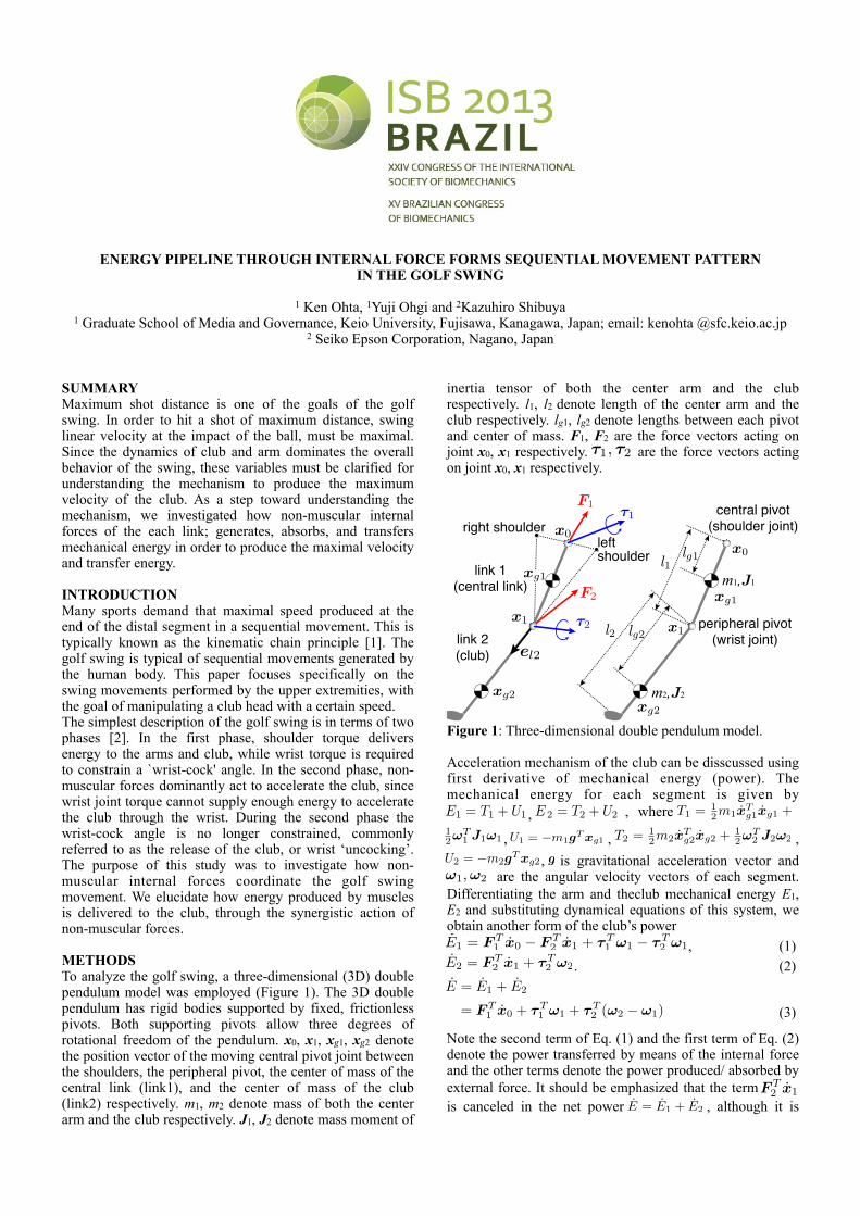
METHODSTo analyze the golf swing, a three-dimensional (3D) double pendulum model was employed (Figure 1). The 3D double pendulum has rigid bodies supported by fixed, frictionless pivots. Both supporting pivots allow three degrees of rotational freedom of the pendulum. x0, x1, xg1, xg2 denote the position vector of the moving central pivot joint between the shoulders, the peripheral pivot, the center of mass of the central link (link1), and the center of mass of the club (link2) respectively. m1, m2 denote mass of both the center arm and the club respectively. J1, J2 denote mass moment of
inertia tensor of both the center arm and the club respectively. l1, l2 denote length of the center arm and the club respectively. lg1, lg2 denote lengths between each pivot and center of mass. F1, F2 are the force vectors acting on joint x0, x1 respectively. �1, �2 are the force vectors acting on joint x0, x1 respectively.
link 1(central link)
leftshoulder
peripheral pivot(wrist joint)
central pivot(shoulder joint)right shoulder
link 2(club) el2
m1,J1
m2,J2
F2
F1!1
!2
lg1
lg2
l1
l2
xg1
xg1
xg2
xg2
x1x1
x0
x0
Figure 1: Three-dimensional double pendulum model.
Acceleration mechanism of the club can be disscussed using first derivative of mechanical energy (power). The mechanical energy for each segment is given by E1 = T1 + U1 , E 2 = T2 + U2 , where T1 = 1
2m1xTg1xg1 +
12!
T1 J1!1 , U1 = �m1gT xg1 , T2 = 1
2m2xTg2xg2 + 1
2�T2 J2�2 ,
U2 = �m2gT xg2 , g is gravitational acceleration vector and �1,�2 are the angular velocity vectors of each segment. Differentiating the arm and theclub mechanical energy E1, E2 and substituting dynamical equations of this system, we obtain another form of the club’s powerE1 = F T
1 x0 � F T2 x1 + �T
1 �1 � �T2 �1, (1)
E2 = F T2 x1 + �T
2 �2 . (2)E = E1 + E2
= F T1 x0 + !T
1 "1 + !T2 ("2 ! "1)
(3)
Note the second term of Eq. (1) and the first term of Eq. (2) denote the power transferred by means of the internal force and the other terms denote the power produced/ absorbed by external force. It should be emphasized that the term F T
2 x1 is canceled in the net power E = E1 + E2 , although it is
shown in both E1, E2 . This indicates an internal force F2 transfers the energy among segments. This works as an energy pipeline among the adjacent segments, although it does not affect the entire energy. Despite playing an important role within the system, the internal force F2 cannot be expressed in minimum coordinates set such as Lagrange equations, since the internal force does not affect the mechanical energy of the entire system. Only redundant coordinates formulation, such as Newton-Euler equations can explicitly express the effect of the internal force among segments.
One right handed male golfer participated in this study and executed a series of drives. His arm and club motions were recorded by motion capture system (Vicon MX system) at 500 Hz. The data were analyzed between top of downswing (-0.3 s) and impact (0.0 s). Spherical reflective markers were attached on each club and arms to identify position vectors and attitudes of each link. A nonparametric spline smoothing method for time series was used to smooth the position vectors [*] and the smoothed data were used for the following analysis.
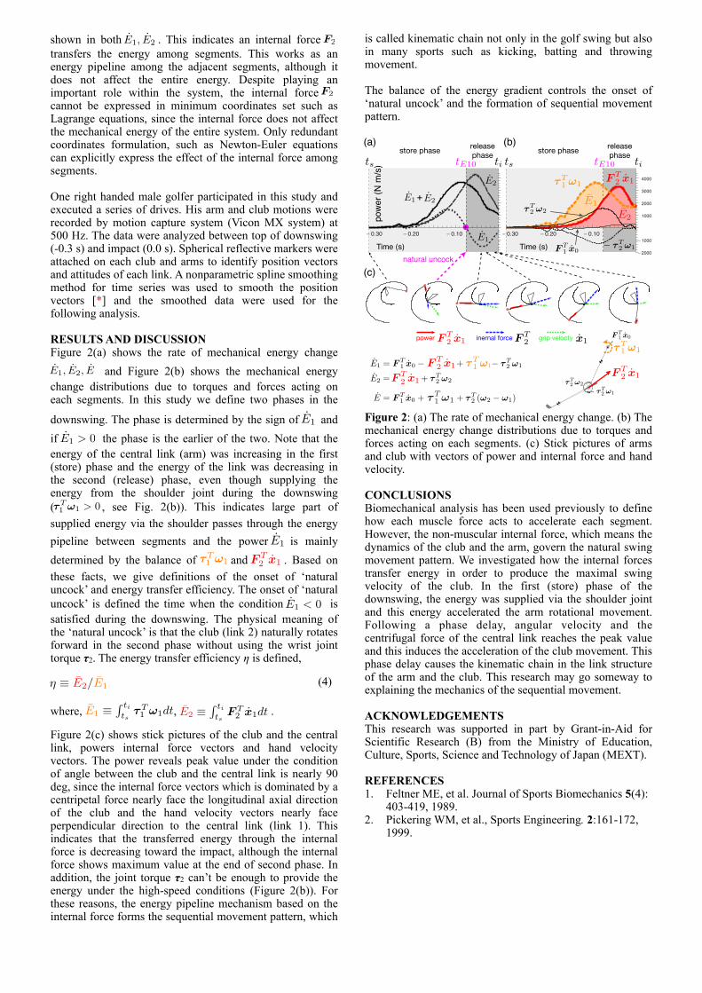
RESULTS AND DISCUSSIONFigure 2(a) shows the rate of mechanical energy change E1, E2, E and Figure 2(b) shows the mechanical energy change distributions due to torques and forces acting on each segments. In this study we define two phases in the downswing. The phase is determined by the sign of E1 and if E1 > 0 the phase is the earlier of the two. Note that the energy of the central link (arm) was increasing in the first (store) phase and the energy of the link was decreasing in the second (release) phase, even though supplying the energy from the shoulder joint during the downswing (!T
1 "1 > 0 , see Fig. 2(b)). This indicates large part of supplied energy via the shoulder passes through the energy pipeline between segments and the power E1 is mainly determined by the balance of !T
1 "1 and F T2 x1 . Based on
these facts, we give definitions of the onset of ‘natural uncock’ and energy transfer efficiency. The onset of ‘natural uncock’ is defined the time when the condition E1 < 0 is satisfied during the downswing. The physical meaning of the ‘natural uncock’ is that the club (link 2) naturally rotates forward in the second phase without using the wrist joint torque τ2. The energy transfer efficiency η is defined,
! ! E2/E1 (4)
where, E1 ! tits
!T1 "1dt, E2 ! ti
tsF T2 x1dt
.
Figure 2(c) shows stick pictures of the club and the central link, powers internal force vectors and hand velocity vectors. The power reveals peak value under the condition of angle between the club and the central link is nearly 90 deg, since the internal force vectors which is dominated by a centripetal force nearly face the longitudinal axial direction of the club and the hand velocity vectors nearly face perpendicular direction to the central link (link 1). This indicates that the transferred energy through the internal force is decreasing toward the impact, although the internal force shows maximum value at the end of second phase. In addition, the joint torque τ2 can’t be enough to provide the energy under the high-speed conditions (Figure 2(b)). For these reasons, the energy pipeline mechanism based on the internal force forms the sequential movement pattern, which
is called kinematic chain not only in the golf swing but also in many sports such as kicking, batting and throwing movement.
The balance of the energy gradient controls the onset of ‘natural uncock’ and the formation of sequential movement pattern.
Time (s) Time (s)E1 ! !T
2 "1
pow
er (N
m/s
)
E2
+ E2E1
(a)
(c)
(b)
F T2 x1
E1 = F T1 x0 ! F T
2 x1+ !T1 "1! !T
2 "1
E2 =F T2 x1 + ! T
2 "2
E = F T1 x0 + !T
1 "1 + !T2 ("2 ! "1)
! 0.30 ! 0.20 ! 0.10 ! 0.30 ! 0.20 ! 0.10
!2000
!1000
1000
2000
3000
4000!T1 "1
!T2 "2
F T1 x0
F T1 x0
!T1 "1
! !T2 "1
F T2
F T2
x1
F T2 x1 x1
!T2 "2
store phase releasephase store phase release
phase
power inernal force grip velocty
ts titE10 ts titE10
natural uncock
E1
E2
Figure 2: (a) The rate of mechanical energy change. (b) The mechanical energy change distributions due to torques and forces acting on each segments. (c) Stick pictures of arms and club with vectors of power and internal force and hand velocity.
CONCLUSIONSBiomechanical analysis has been used previously to define how each muscle force acts to accelerate each segment. However, the non-muscular internal force, which means the dynamics of the club and the arm, govern the natural swing movement pattern. We investigated how the internal forces transfer energy in order to produce the maximal swing velocity of the club. In the first (store) phase of the downswing, the energy was supplied via the shoulder joint and this energy accelerated the arm rotational movement. Following a phase delay, angular velocity and the centrifugal force of the central link reaches the peak value and this induces the acceleration of the club movement. This phase delay causes the kinematic chain in the link structure of the arm and the club. This research may go someway to explaining the mechanics of the sequential movement.
ACKNOWLEDGEMENTSThis research was supported in part by Grant-in-Aid for Scientific Research (B) from the Ministry of Education, Culture, Sports, Science and Technology of Japan (MEXT).
REFERENCES1. Feltner ME, et al. Journal of Sports Biomechanics 5(4):
403-419, 1989.2. Pickering WM, et al., Sports Engineering. 2:161-172,
1999.


![Statics - TAM 211Work [joule (J)]: Energy change over a period of time as a result of a force (or moment) acting through a translational (or rotational) displacement Measure of energy](https://img.pdfslide.us/doc/110x75/60ad5257f27ba14b6b287700/statics-tam-211-work-joule-j-energy-change-over-a-period-of-time-as-a-result.jpg)