Embed Size (px)
Citation preview
Energy Piles : Background and Geotechnical Engineering Concepts
16th Annual George F. Sowers SymposiumAtlanta, GA / May 7, 2013
C. Guney OlgunCivil & Environmental Engineering
Virginia Tech

Outline
Background and concept
Geothermal heat-exchange systems, energy piles
Performance and geotechnical challenges
Design of energy piles
Summary and conclusions
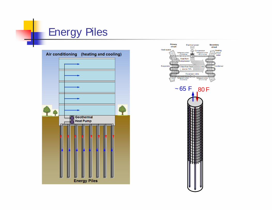
Energy Piles
80 F~65 F
Courtesy J. Wheeler / Virginia Tech
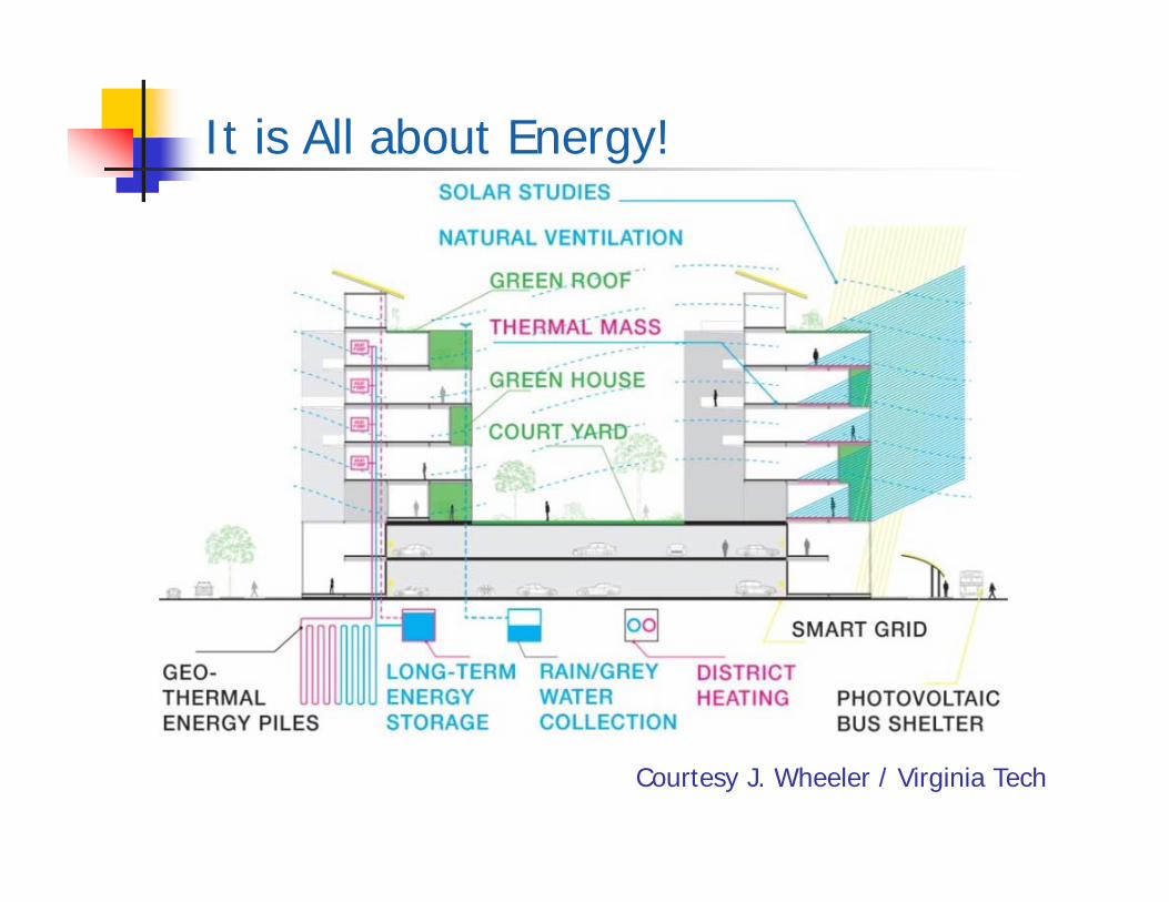
It is All about Energy!
Courtesy J. Wheeler / Virginia Tech
Globally Increasing Need for Renewable Energy
Driving factors – rising global energy demand and need to reduce carbon emissions (i.e., recent UK codes require zero-carbon buildings by 2019, U.S. executive order)
Buildings generate 43% of US carbon emissions
Considerable electricity consumption due to heating/cooling
Electricity generation is largest source of air pollution in US
Commercial and residential buildings consume 71% of US electricity
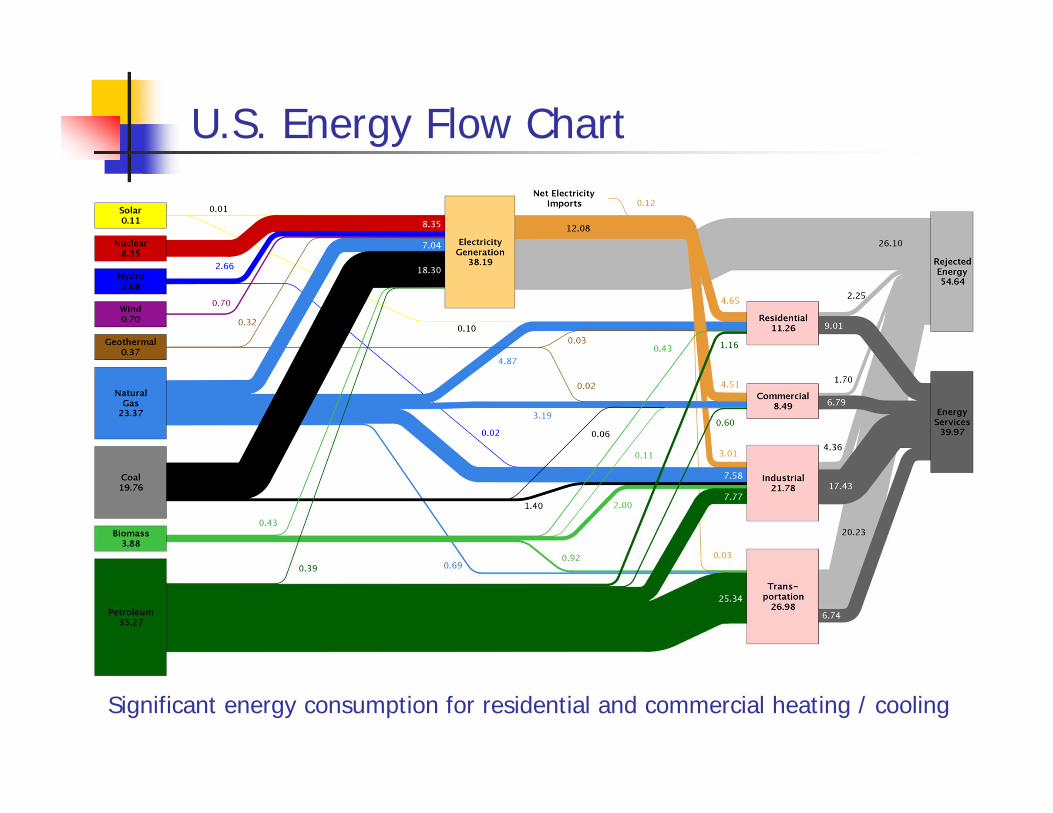
U.S. Energy Flow Chart
Significant energy consumption for residential and commercial heating / cooling
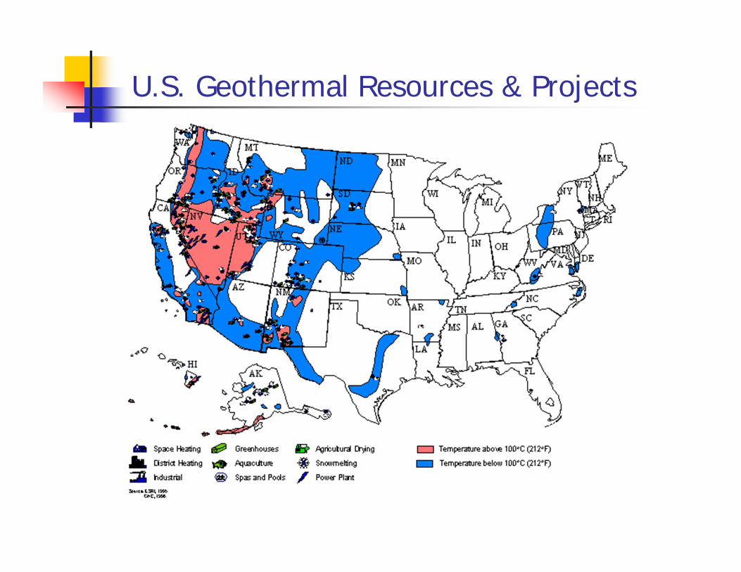
U.S. Geothermal Resources & Projects
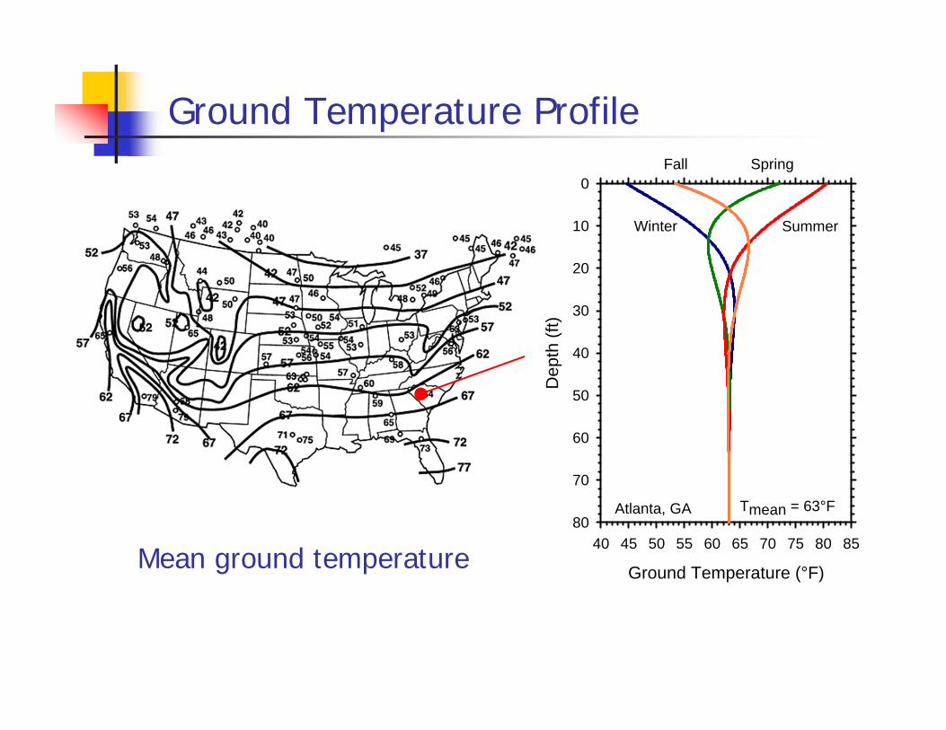
Ground Temperature Profile
Mean ground temperature Ground Temperature (°F)
40 45 50 55 60 65 70 75 80 85D
epth
(ft)
0
10
20
30
40
50
60
70
80
Summer
Spring
Winter
Fall
Tmean = 63°FAtlanta, GA
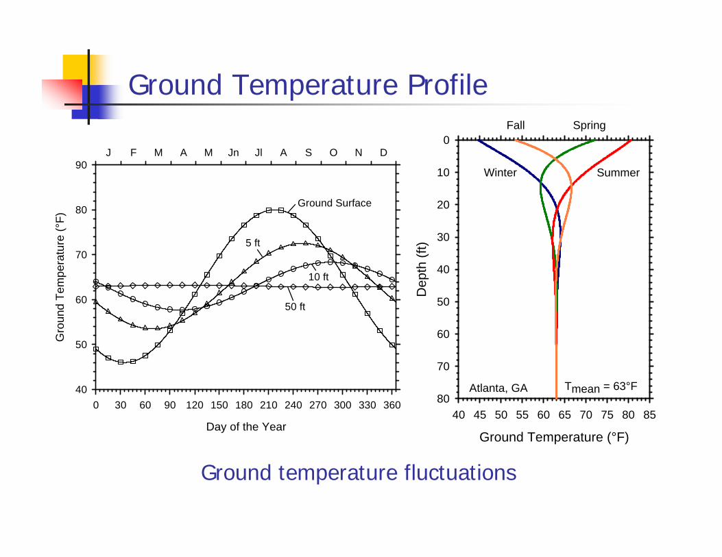
Ground Temperature Profile
Ground temperature fluctuations
Ground Temperature (°F)
40 45 50 55 60 65 70 75 80 85D
epth
(ft)
0
10
20
30
40
50
60
70
80
Summer
Spring
Winter
Fall
Tmean = 63°FAtlanta, GA
J F M A M Jn Jl A S O N D
Gro
und
Tem
pera
ture
(°F)
40
50
60
70
80
90
Day of the Year
0 30 60 90 120 150 180 210 240 270 300 330 360
Ground Surface
5 ft
10 ft
50 ft
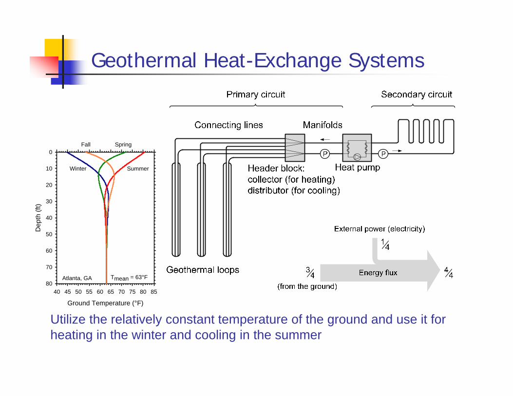
Geothermal Heat-Exchange Systems
Utilize the relatively constant temperature of the ground and use it for heating in the winter and cooling in the summer
Ground Temperature (°F)
40 45 50 55 60 65 70 75 80 85
Dep
th (f
t)
0
10
20
30
40
50
60
70
80
Summer
Spring
Winter
Fall
Tmean = 63°FAtlanta, GA

Ground Source Heating/Cooling
Geothermal heat exchange systems provide ground-source energy for heating and cooling
The use of ground-source systems for heating and cooling has increased exponentially especially in Europe
Basic idea been around for long time – make use of the heat energy stored in the ground; access this energy using heat exchangers buried in the ground (fluid-filled HDPE loops)
In ideal conditions these systems can provide majority of required heating/cooling energy and significantly reduce costs and carbon footprint
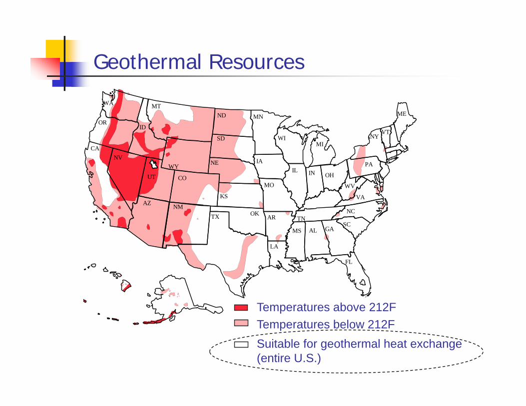
Geothermal Resources
OR
CA
NMOKTX
MN
IA
MO
AR
LA
WI
IL IN
TN
MS
MI
OH
AL GASC
NC
VA
WV
NYVT
ME
Temperature above 100oC (212oF)
AZ
ID
WA
CO
ND
SD
NE
KS
WY PANV
UT
MT
FL
Temperature below 100oC (212oF)
Area suitable for "Geothermal Foundation(entire U.S.)
Temperatures above 212FTemperatures below 212FSuitable for geothermal heat exchange (entire U.S.)

Outline
Background and concept
Geothermal heat-exchange systems, energy piles
Performance and geotechnical challenges
Design of energy piles
Summary and conclusions
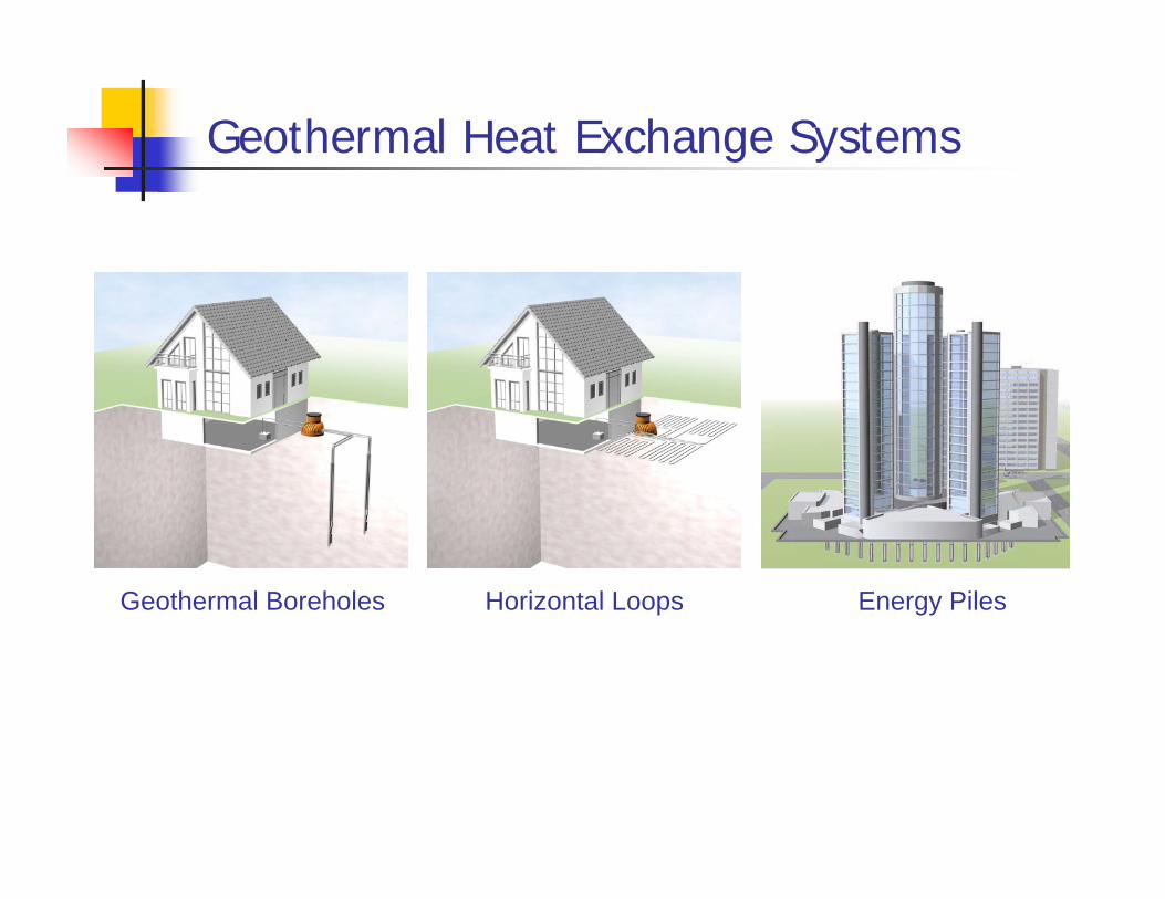
Geothermal Heat Exchange Systems
Geothermal Boreholes Horizontal Loops Energy Piles
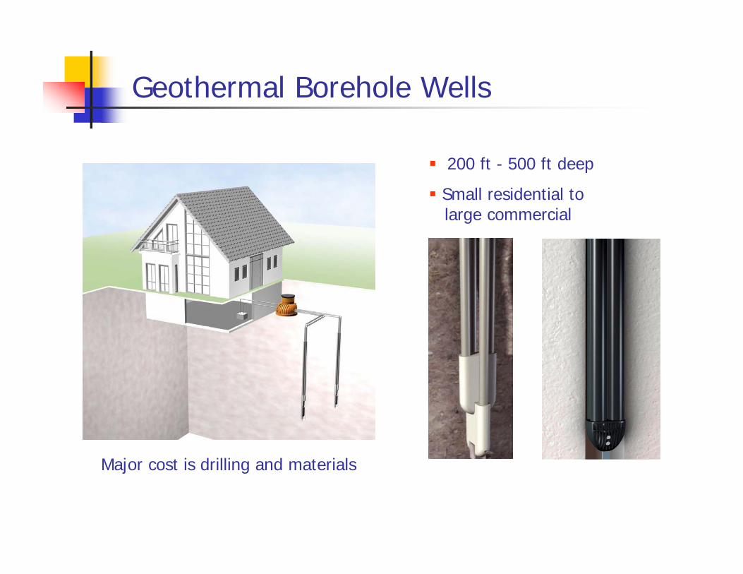
Geothermal Borehole Wells
200 ft - 500 ft deep
Small residential tolarge commercial
Major cost is drilling and materials
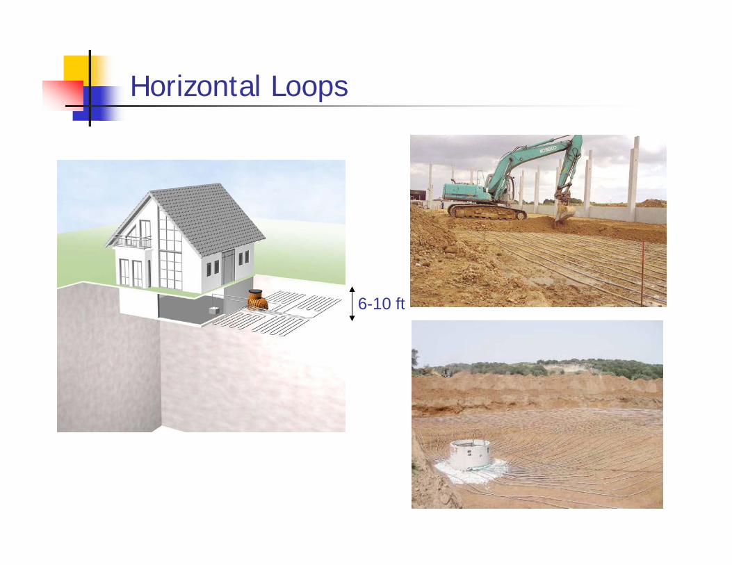
Horizontal Loops
6-10 ft
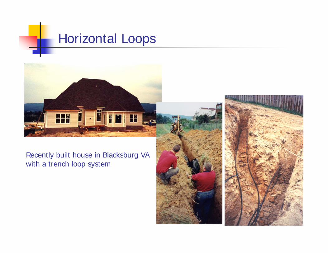
Horizontal Loops
Recently built house in Blacksburg VA with a trench loop system
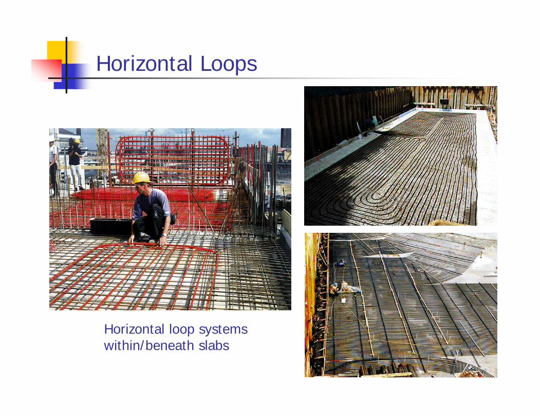
Horizontal Loops
Horizontal loop systems within/beneath slabs
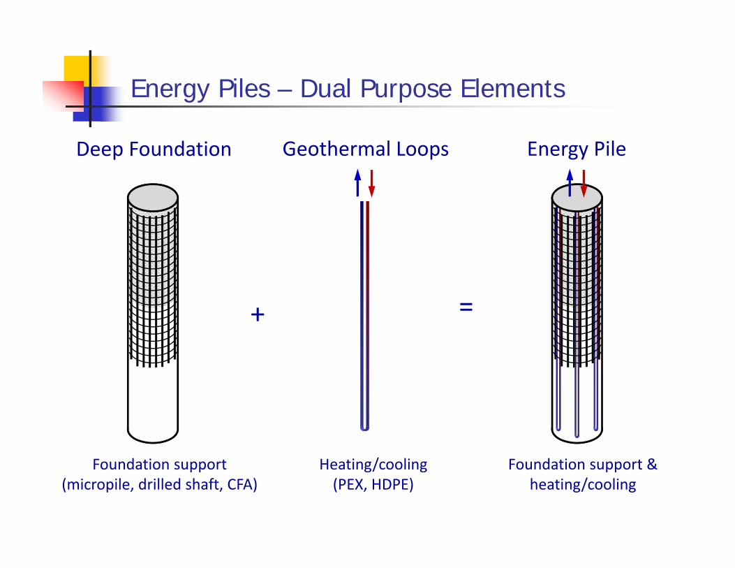
Energy Piles – Dual Purpose Elements
Foundation support(micropile, drilled shaft, CFA)
Heating/cooling(PEX, HDPE)
Foundation support & heating/cooling
Geothermal LoopsDeep Foundation Energy Pile
+ =
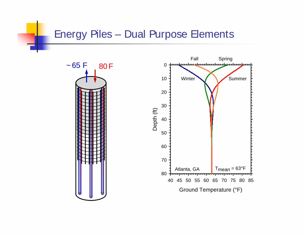
Energy Piles – Dual Purpose Elements
80 F~65 F
Ground Temperature (°F)
40 45 50 55 60 65 70 75 80 85
Dep
th (f
t)
0
10
20
30
40
50
60
70
80
Summer
Spring
Winter
Fall
Tmean = 63°FAtlanta, GA
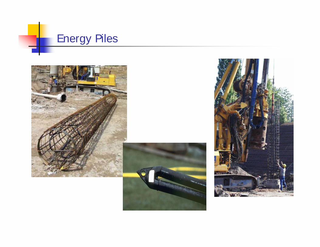
Energy Piles
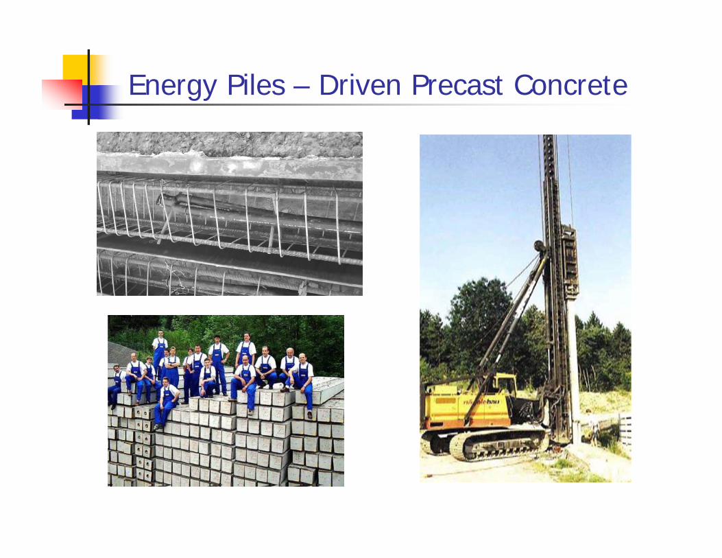
Energy Piles – Driven Precast Concrete
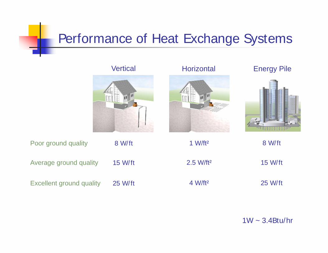
Performance of Heat Exchange Systems
Poor ground quality
Average ground quality
Excellent ground quality
8 W/ft
15 W/ft
25 W/ft
1 W/ft²
2.5 W/ft²
4 W/ft²
8 W/ft
15 W/ft
25 W/ft
Vertical Horizontal Energy Pile
1W ~ 3.4Btu/hr
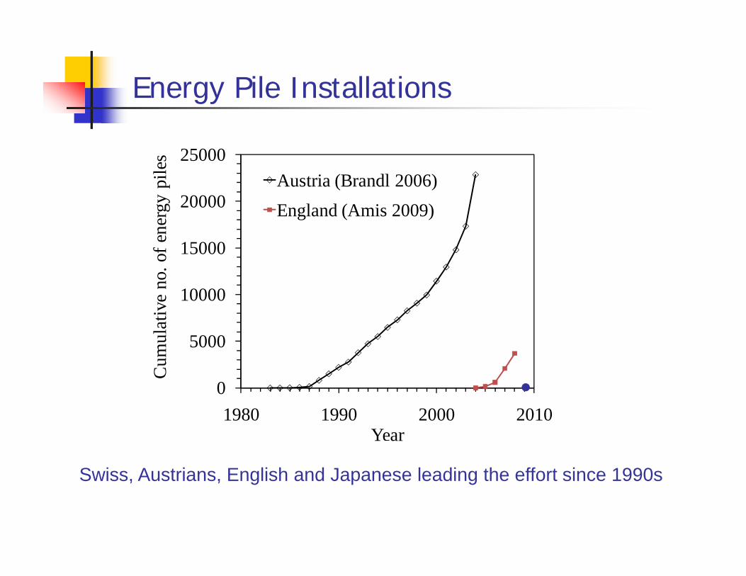
Energy Pile Installations
0
5000
10000
15000
20000
25000
1980 1990 2000 2010
Cum
ulat
ive
no. o
f ene
rgy
pile
s
Year
Austria (Brandl 2006)England (Amis 2009)
Swiss, Austrians, English and Japanese leading the effort since 1990s

Frankfurt Main Tower
223 Energy piles were installedPower : 500kWCourtesy R. Katzenbach TUD
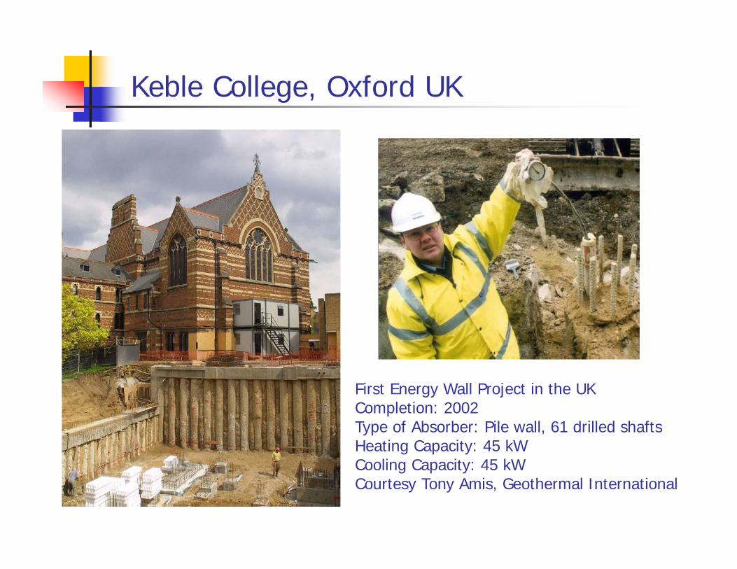
Keble College, Oxford UK
First Energy Wall Project in the UKCompletion: 2002Type of Absorber: Pile wall, 61 drilled shaftsHeating Capacity: 45 kWCooling Capacity: 45 kWCourtesy Tony Amis, Geothermal International

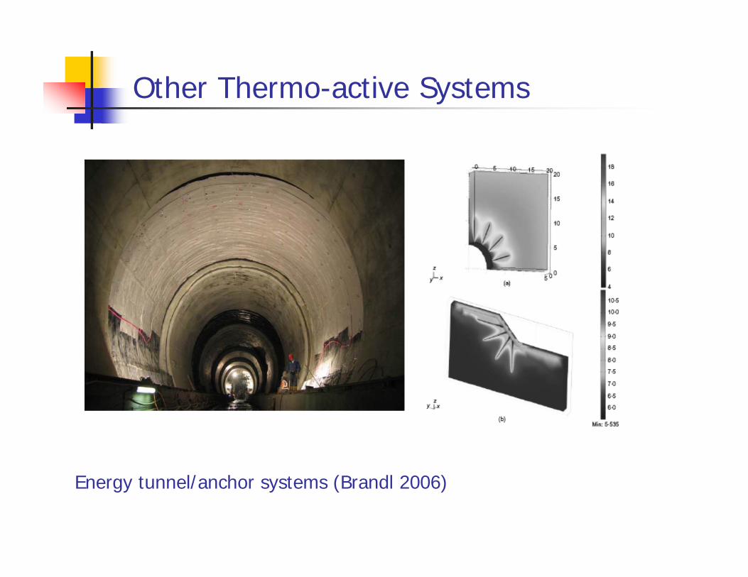
Other Thermo-active Systems
Energy tunnel/anchor systems (Brandl 2006)
Other Thermo-active Systems
Energy tunnel/anchor systems (Brandl 2006)

Other Thermo-active Systems
Knightsbridge Palace Hotel – Loop Installation into Energy Wall (Courtesy Tony Amis, Geothermal International)
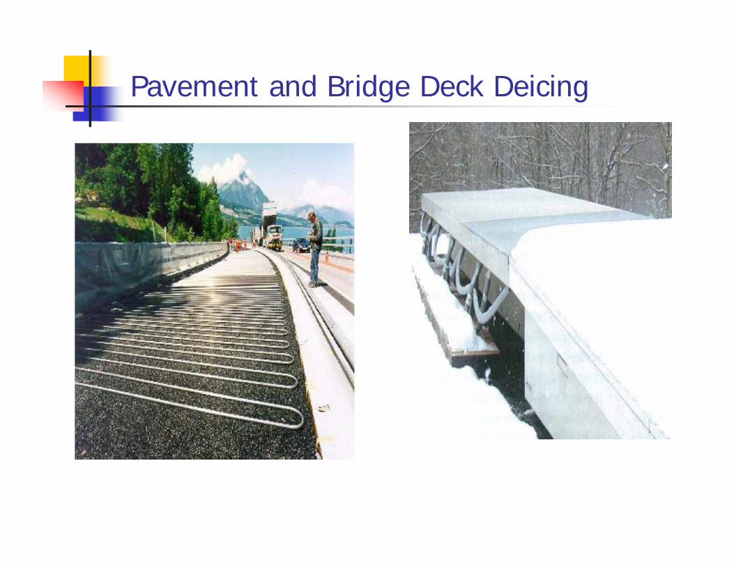
Pavement and Bridge Deck Deicing

Geothermal Bridge Deck Deicing
Bridge Deck Deicing Using Energy Piles
Energy Piles
Loops Embedded in the Approach Embankment
Plan View of the Bridge Deck
Small-scale Bridge Deck Slab (8 ft x 10 ft)
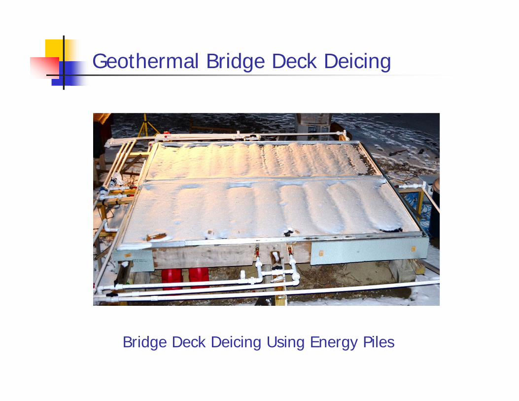
Geothermal Bridge Deck Deicing
Bridge Deck Deicing Using Energy Piles

Ground-source Grain Drying
Fan connected to a geothermal borehole system or energy foundation and forces air through grains which eliminates grain moisture
Advantages of Thermo-active Foundations
Environmentally-friendly, with relatively little power demand
Help reduce fossil fuel demand, decreasing CO2 emissions
Low maintenance and long lifetime
Installation in foundation permits heat exchange system to be within building footprint, making more efficient use of material and space
Offer more opportunities for radiant heating/cooling with better humidity control
Less vulnerable to variation in energy source than hydropower (droughts), wind, and solar
Less sensitive to energy price fluctuations

Outline
Background and concept
Geothermal heat-exchange systems, energy piles
Performance and geotechnical challenges
Design of energy piles
Summary and conclusions

Effect of Ground Cooling
Ground cooling reduces stresses along pile cross-section, can cause tensile stresses
Structural Load Load + Cooling
Ski
n fri
ctio
n
Soil Resistance
Axial Load
Cooling
+ =
Axial Load
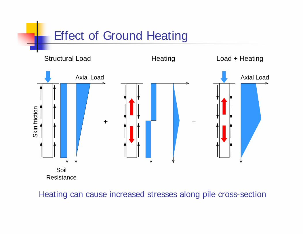
Effect of Ground Heating
Heating can cause increased stresses along pile cross-section
Structural Load Load + Heating
Ski
n fri
ctio
n
Soil Resistance
Axial Load
Heating
+ =
Axial Load
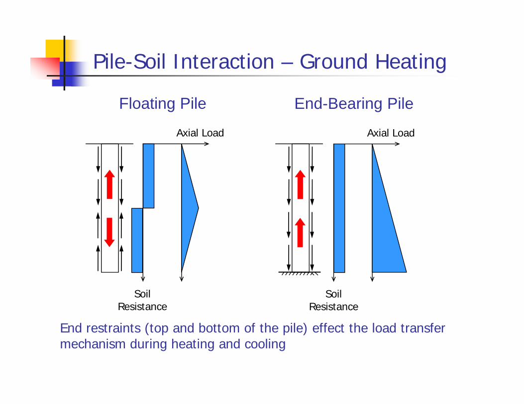
Pile-Soil Interaction – Ground Heating
Soil Resistance
Axial Load
Floating Pile
Soil Resistance
Axial Load
End-Bearing Pile
End restraints (top and bottom of the pile) effect the load transfer mechanism during heating and cooling

Effect of End Bearing on Thermal Stresses
K. Soga / T. Amis – Lambeth College L. Laloui - EPFL
Normal Stress at Pile Cross Section (kPa)0 50 100 150 200 250 300 350
Dep
th (m
)
0
5
10
15
20
25
30
(psi)0 10 20 30 40 50
Dep
th (f
t)
0
20
40
60
80
Structural
Thermal+ Structural
Axial Pile Load (kN)0 500 1000 1500 2000
Dep
th (m
)
0
5
10
15
20
25
(kips)0 100 200 300 400
Dep
th (f
t)
0
10
20
30
40
50
60
70
80
Structural
Thermal+ Structural
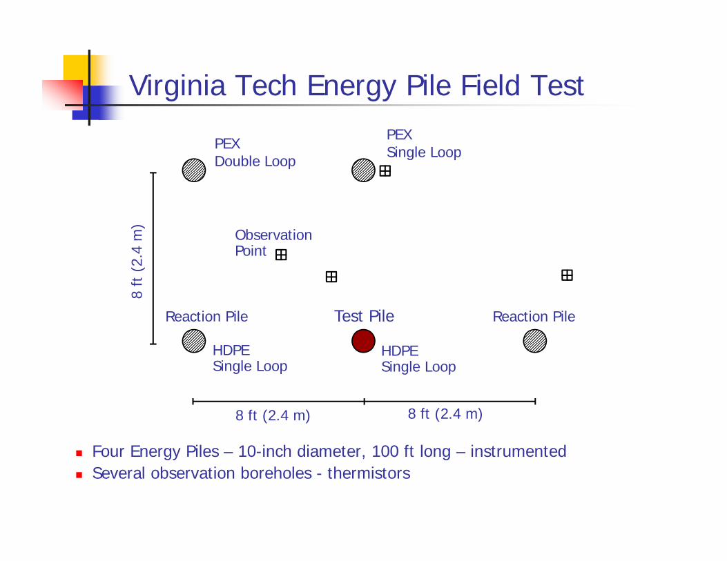
Virginia Tech Energy Pile Field Test
Four Energy Piles – 10-inch diameter, 100 ft long – instrumented Several observation boreholes - thermistors
PEX Single LoopPEX
Double Loop
HDPE Single Loop
HDPE Single Loop
Observation Point
Test Pile
8 ft (2.4 m) 8 ft (2.4 m)
8 ft
(2.
4 m
)
Reaction Pile Reaction Pile
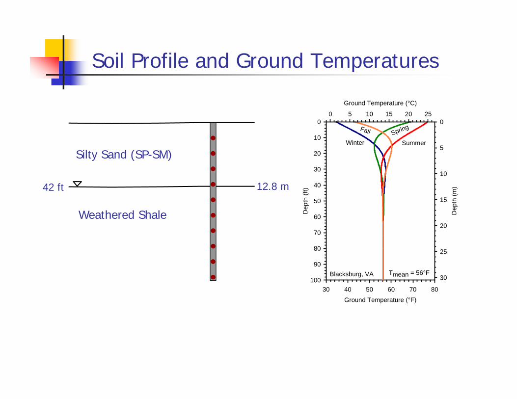
Soil Profile and Ground Temperatures
Ground Temperature (°F)30 40 50 60 70 80
Dep
th (f
t)
0
10
20
30
40
50
60
70
80
90
100
Ground Temperature (°C)
0 5 10 15 20 25
Dep
th (m
)
0
5
10
15
20
25
30
SummerSpring
Winter
Fall
Tmean = 56°FBlacksburg, VA
Silty Sand (SP-SM)
Weathered Shale
42 ft 12.8 m

Circulation Loops
HDPE Geothermal Loop and U-Bend
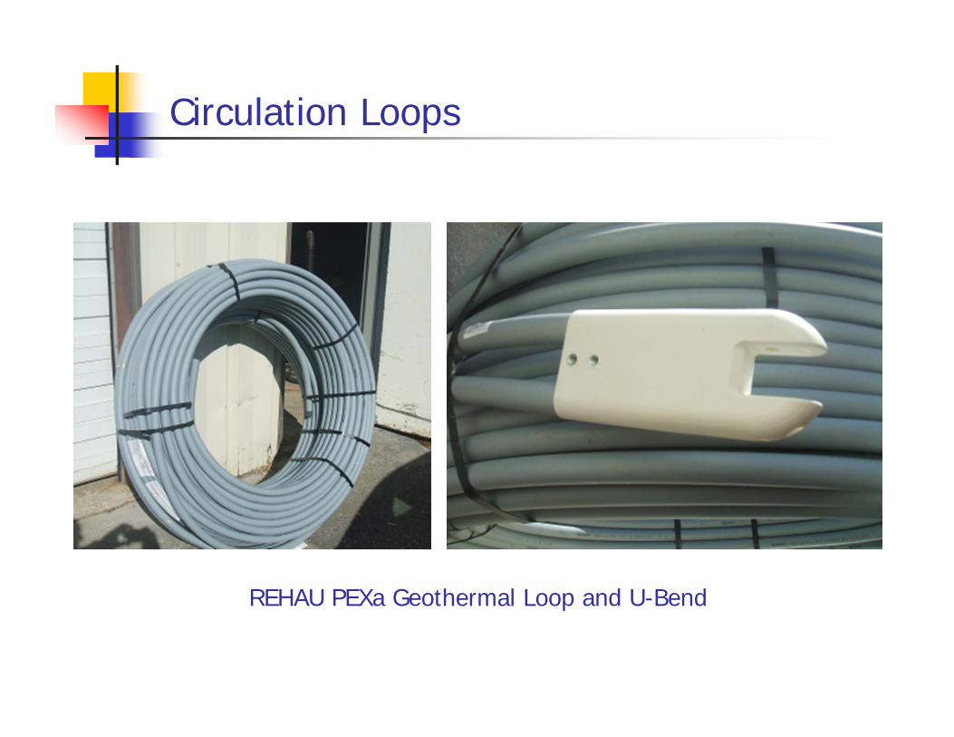
Circulation Loops
REHAU PEXa Geothermal Loop and U-Bend

Energy Pile Installation
Drilling
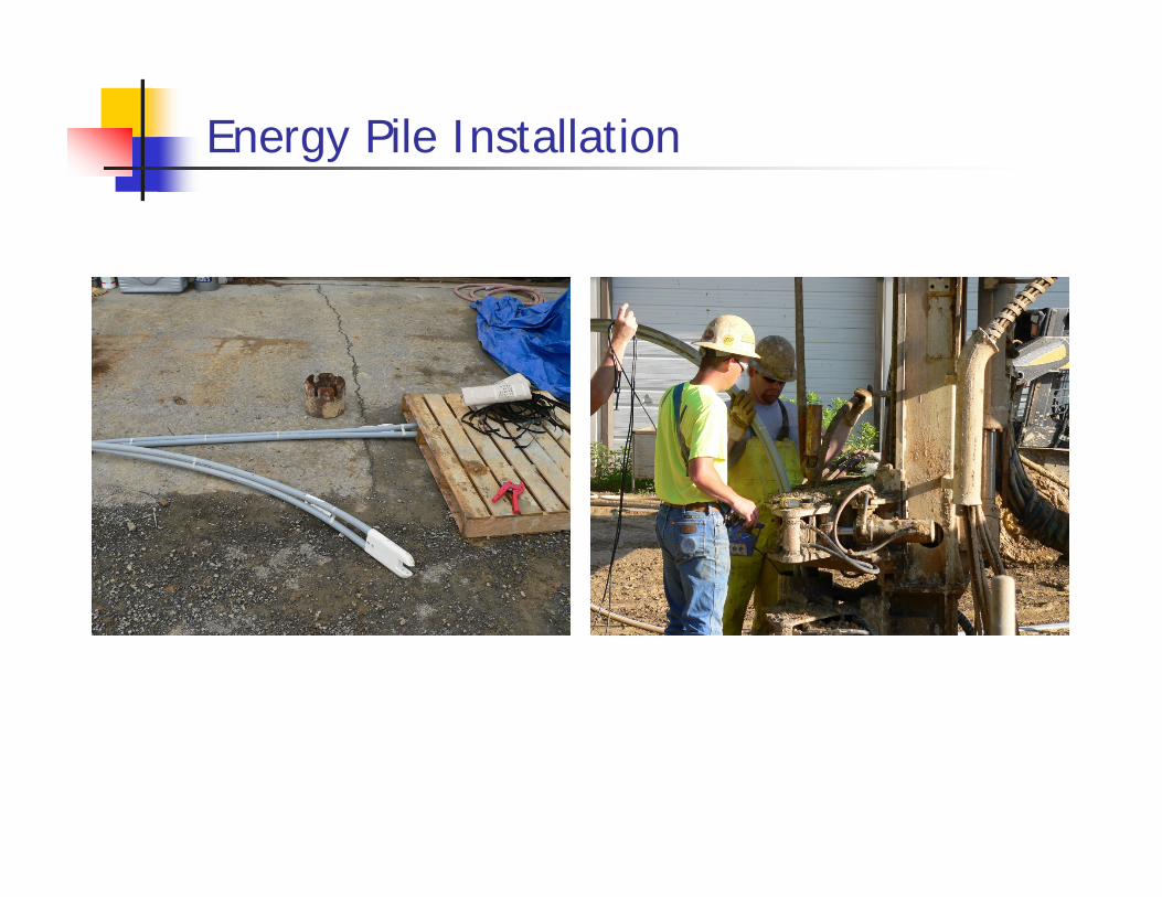
Energy Pile Installation
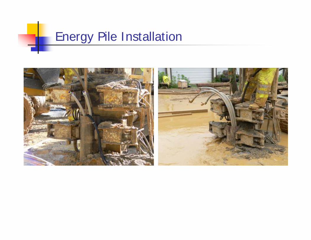
Energy Pile Installation
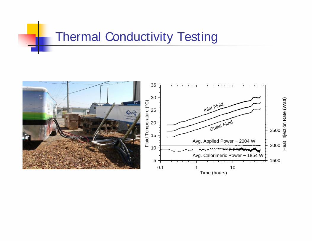
Thermal Conductivity Testing
Time (hours)0.1 1 10
Flui
d Te
mpe
ratu
re (°
C)
5
10
15
20
25
30
35
Hea
t Inj
ectio
n R
ate
(Wat
t)
1500
2000
2500
Avg. Calorimeric Power ~ 1854 W
Avg. Applied Power ~ 2004 W
Inlet Fluid
Outlet Fluid

Virginia Tech – Energy Pile Test Site
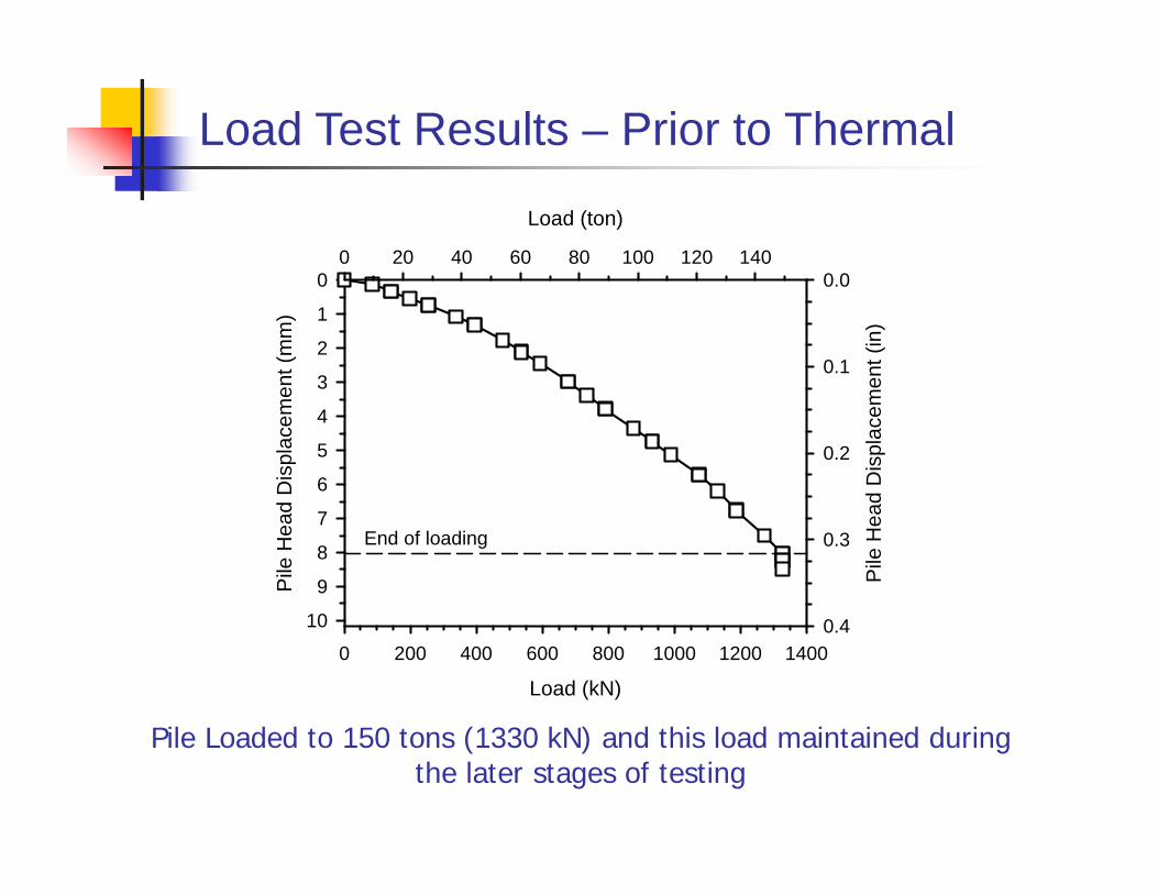
Load Test Results – Prior to Thermal
Load (kN)
0 200 400 600 800 1000 1200 1400
Pile
Hea
d D
ispl
acem
ent (
mm
)0
1
2
3
4
5
6
7
8
9
10
Load (ton)
0 20 40 60 80 100 120 140
Pile
Hea
d D
ispl
acem
ent (
in)
0.0
0.1
0.2
0.3
0.4
End of loading
Pile Loaded to 150 tons (1330 kN) and this load maintained during the later stages of testing

Pile Load (ton)0 25 50 75 100 125 150 175 200
Dep
th (f
t)
0
10
20
30
40
50
60
70
80
90
100
Pile Load (kN)
0 250 500 750 1000 1250 1500 1750 2000D
epth
(m)
0
5
10
15
20
25
30
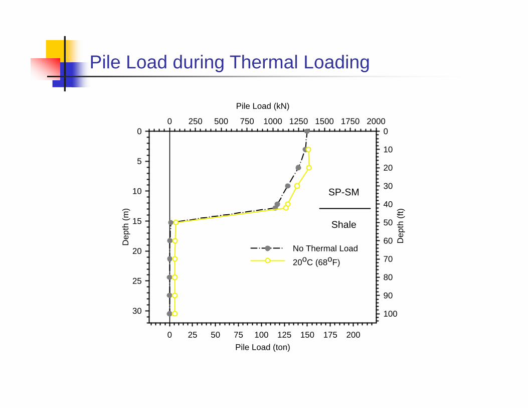
No Thermal Load
SP-SM
Shale
Pile Load prior to Thermal Loading
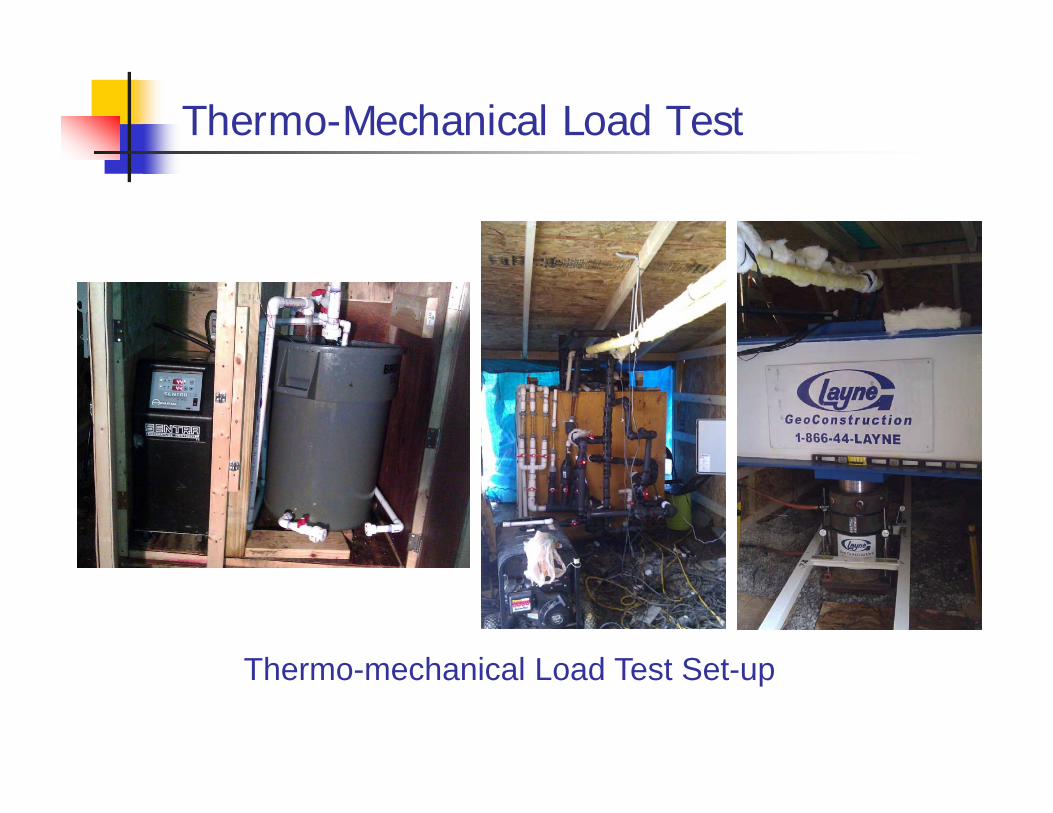
Thermo-Mechanical Load Test
Thermo-mechanical Load Test Set-up
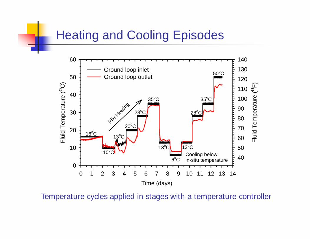
Temperature cycles applied in stages with a temperature controller
Heating and Cooling Episodes
Time (days)0 1 2 3 4 5 6 7 8 9 10 11 12 13 14
Flui
d Te
mpe
ratu
re (o C
)
0
10
20
30
40
50
60
Flui
d Te
mpe
ratu
re (o F)
40
50
60
70
80
90
100
110
120
130
140
Ground loop inletGround loop outlet
16oC
10oC
13oC
20oC
28oC
35oC
13oC
6oC
13oC
28oC
35oC
50oC
Cooling belowin-situ temperature
Pile H
eatin
g
Pile Load (ton)0 25 50 75 100 125 150 175 200
Dep
th (f
t)
0
10
20
30
40
50
60
70
80
90
100
Pile Load (kN)
0 250 500 750 1000 1250 1500 1750 2000D
epth
(m)
0
5
10
15
20
25
30
No Thermal Load20oC (68oF)
SP-SM
Shale
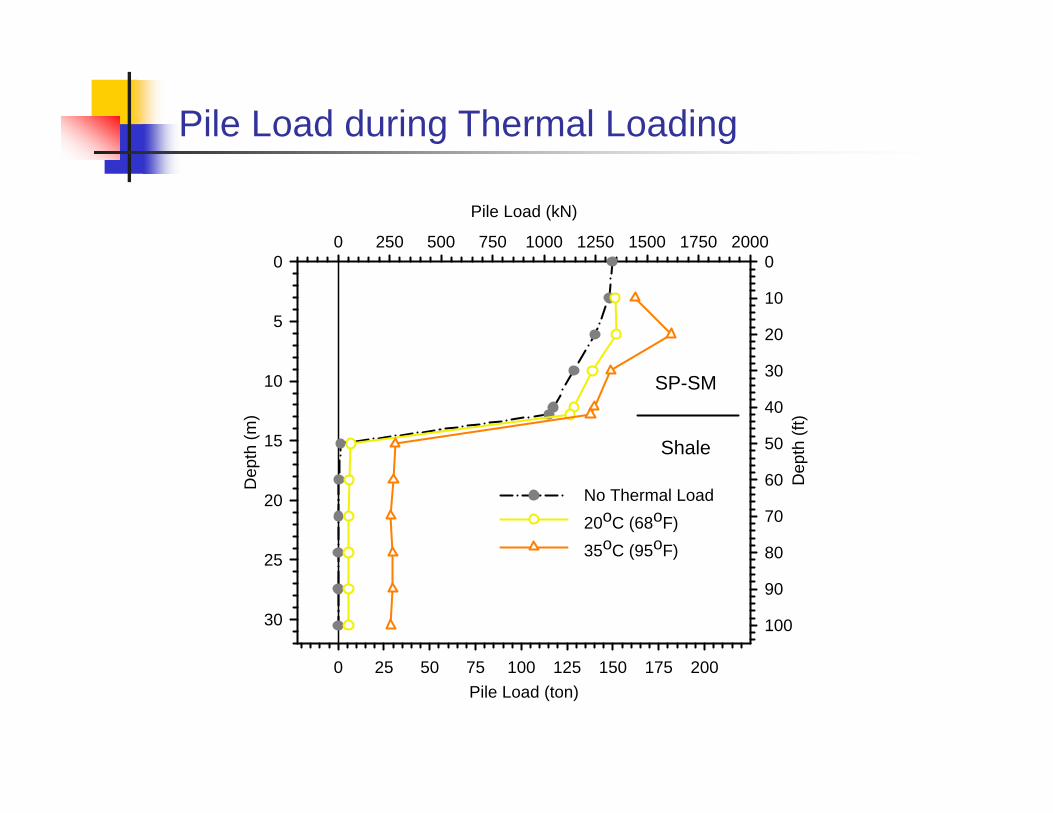
Pile Load during Thermal Loading
Pile Load (ton)0 25 50 75 100 125 150 175 200
Dep
th (f
t)
0
10
20
30
40
50
60
70
80
90
100
Pile Load (kN)
0 250 500 750 1000 1250 1500 1750 2000D
epth
(m)
0
5
10
15
20
25
30
No Thermal Load20oC (68oF)35oC (95oF)
SP-SM
Shale
Pile Load during Thermal Loading
Pile Load (ton)0 25 50 75 100 125 150 175 200
Dep
th (f
t)
0
10
20
30
40
50
60
70
80
90
100
Pile Load (kN)
0 250 500 750 1000 1250 1500 1750 2000D
epth
(m)
0
5
10
15
20
25
30
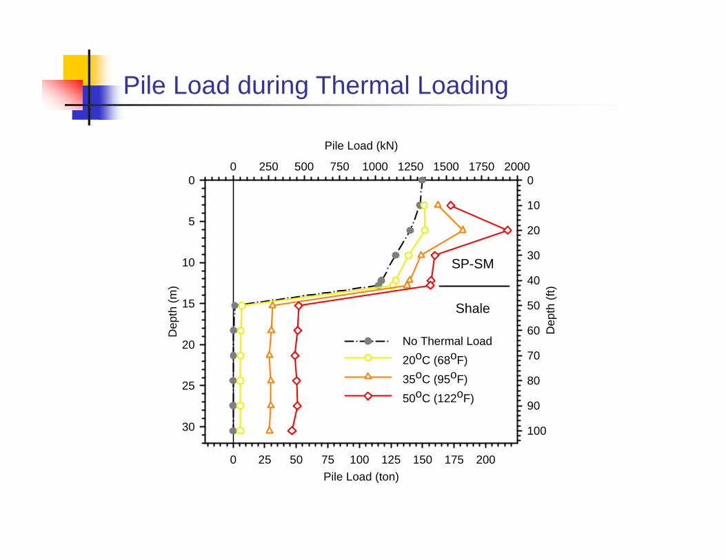
No Thermal Load20oC (68oF)35oC (95oF)50oC (122oF)
SP-SM
Shale
Pile Load during Thermal Loading

Pile Load (ton)0 25 50 75 100 125 150 175 200
Dep
th (f
t)
0
10
20
30
40
50
60
70
80
90
100
Pile Load (kN)
0 250 500 750 1000 1250 1500 1750 2000D
epth
(m)
0
5
10
15
20
25
30
No Thermal Load20oC (68oF)35oC (95oF)50oC (122oF)6oC (43oF)
SP-SM
Shale
Pile Load during Thermal Loading

Years of Heat Pump Operation0 5 10 15 20 25 30
Gro
und
Tem
pera
ture
(°C
)
232425262728293031
Gro
und
Tem
pera
ture
(°F)
74
76
78
80
82
84
86
Long Term Performance of Energy Piles
Houston TX
Barriers to Wider Use
Lack of refined design standards – current methods to estimate field conductivity developed for geothermal boreholes; we need geotechnical engineers to provide leadership not mechanical engineers
Lack of awareness, regulatory issues, typical way HVAC subcontracts written into projects; difficult to optimize Energy Pile design if not involved early on in project planning
Research questions about thermo-mechanical soil-structure interaction effects, especially long-term behavior
Energy Pile Performance
Performance depends on many site-specific factors, such as soil type (thermal conductivity is key!), ground water depth, initial ground temperature
Best conditions are saturated sands and clays, especially with ground water flow
Thermal yield from an energy pile under favorable ground conditions ~25W/ft
Say heating/cooling load for this facility is about 150 kW or less
Assuming good soil conditions, and using 60-ft long piles, 18-in diameter
We would need about 100 energy piles to supply heating and cooling needs for the Union
Outline
Background and concept
Geothermal heat-exchange systems, energy piles
Performance and geotechnical challenges
Design of energy piles
Summary and conclusions
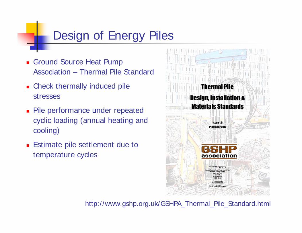
Design of Energy Piles
Ground Source Heat Pump Association – Thermal Pile Standard
Check thermally induced pile stresses
Pile performance under repeated cyclic loading (annual heating and cooling)
Estimate pile settlement due to temperature cycles
http://www.gshp.org.uk/GSHPA_Thermal_Pile_Standard.html
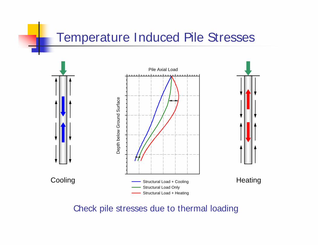
Temperature Induced Pile Stresses
Check pile stresses due to thermal loading
HeatingCooling
Pile Axial Load
Dep
th b
elow
Gro
und
Sur
face
Structural Load + CoolingStructural Load OnlyStructural Load + Heating

Temperature Induced Pile Stresses
Heating and cooling induced pile stresses
HeatingCooling
Pile Length (m)10 15 20 25 30
Add
ition
/Red
uctio
n in
Pile
Axi
al S
tress
-300
-200
-100
0
100
200
300
400
500
600
700
Pile Length (ft)
40 50 60 70 80 90
-6
-4
-2
0
2
4
6
8
10
12
14
Heating
Cooling
20°C (36°F)
10°C (18°F)
-10°C (-18°F)
-20°C (-36°F)
(kPa)
T
(ksf)
from GSHP Thermal Pile Standard
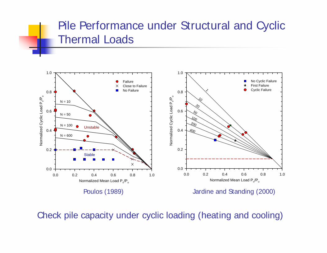
Pile Performance under Structural and Cyclic Thermal Loads
Check pile capacity under cyclic loading (heating and cooling)
Normalized Mean Load Po/Pu
0.0 0.2 0.4 0.6 0.8 1.0
Nor
mal
ized
Cyc
lic L
oad
Pc/P
u
0.0
0.2
0.4
0.6
0.8
1.0
FailureClose to FailureNo Failure
N = 10
N = 50
N = 100
N = 600
Stable
Unstable
Normalized Mean Load Po/Pu
0.0 0.2 0.4 0.6 0.8 1.0N
orm
aliz
ed C
yclic
Loa
d P
c/Pu
0.0
0.2
0.4
0.6
0.8
1.0
No Cyclic Failure First Failure Cyclic Failure 1
10
2050
100
400
200
Poulos (1989) Jardine and Standing (2000)
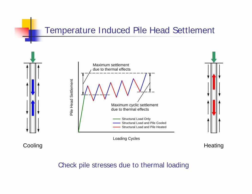
Temperature Induced Pile Head Settlement
Check pile stresses due to thermal loading
HeatingCoolingLoading Cycles
Pile
Hea
d S
ettle
men
t
Structural Load OnlyStructural Load and Pile CooledStructural Load and Pile Heated
Maximum settlementdue to thermal effects
Maximum cyclic settlementdue to thermal effects
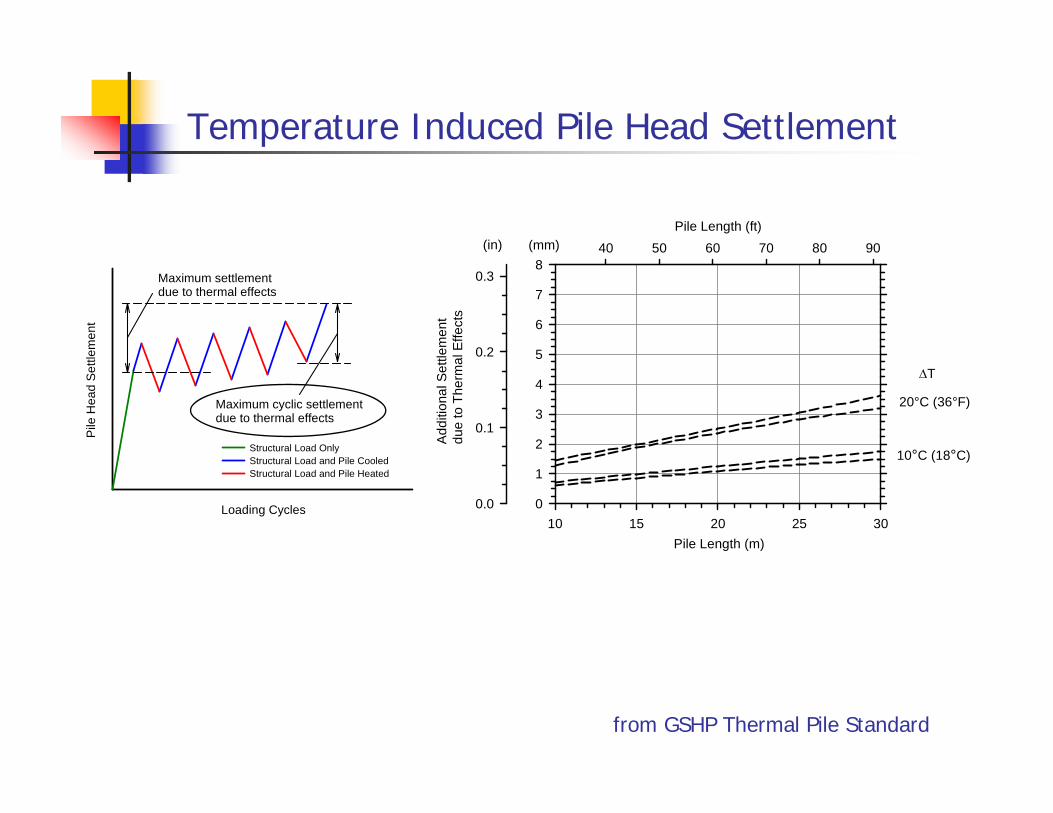
Temperature Induced Pile Head Settlement
Pile Length (m)10 15 20 25 30
Add
ition
al S
ettle
men
t du
e to
The
rmal
Effe
cts
0
1
2
3
4
5
6
7
8
Pile Length (ft)40 50 60 70 80 90
0.0
0.1
0.2
0.3
20°C (36°F)
10°C (18°C)
T
(in) (mm)
Loading Cycles
Pile
Hea
d S
ettle
men
t
Structural Load OnlyStructural Load and Pile CooledStructural Load and Pile Heated
Maximum settlementdue to thermal effects
Maximum cyclic settlementdue to thermal effects
from GSHP Thermal Pile Standard
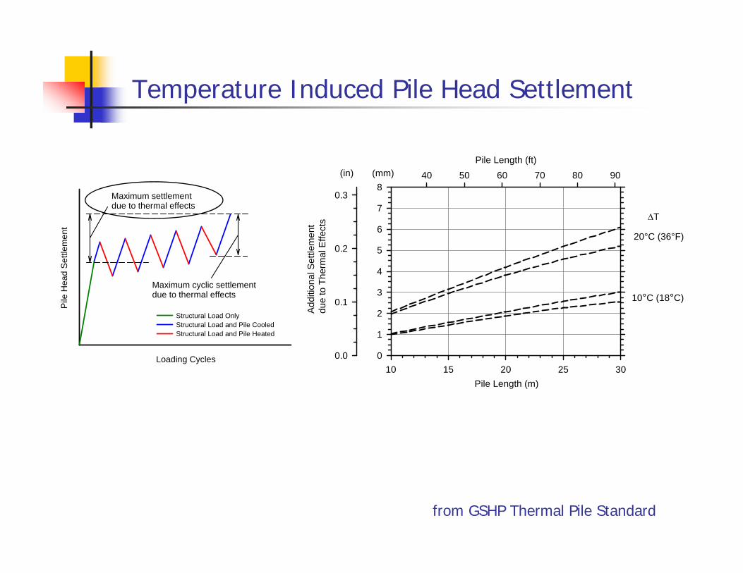
Temperature Induced Pile Head Settlement
Loading Cycles
Pile
Hea
d S
ettle
men
t
Structural Load OnlyStructural Load and Pile CooledStructural Load and Pile Heated
Maximum settlementdue to thermal effects
Maximum cyclic settlementdue to thermal effects
Pile Length (m)10 15 20 25 30
Add
ition
al S
ettle
men
t du
e to
The
rmal
Effe
cts
0
1
2
3
4
5
6
7
8
Pile Length (ft)40 50 60 70 80 90
0.0
0.1
0.2
0.3
20°C (36°F)
10°C (18°C)
T
(in) (mm)
from GSHP Thermal Pile Standard
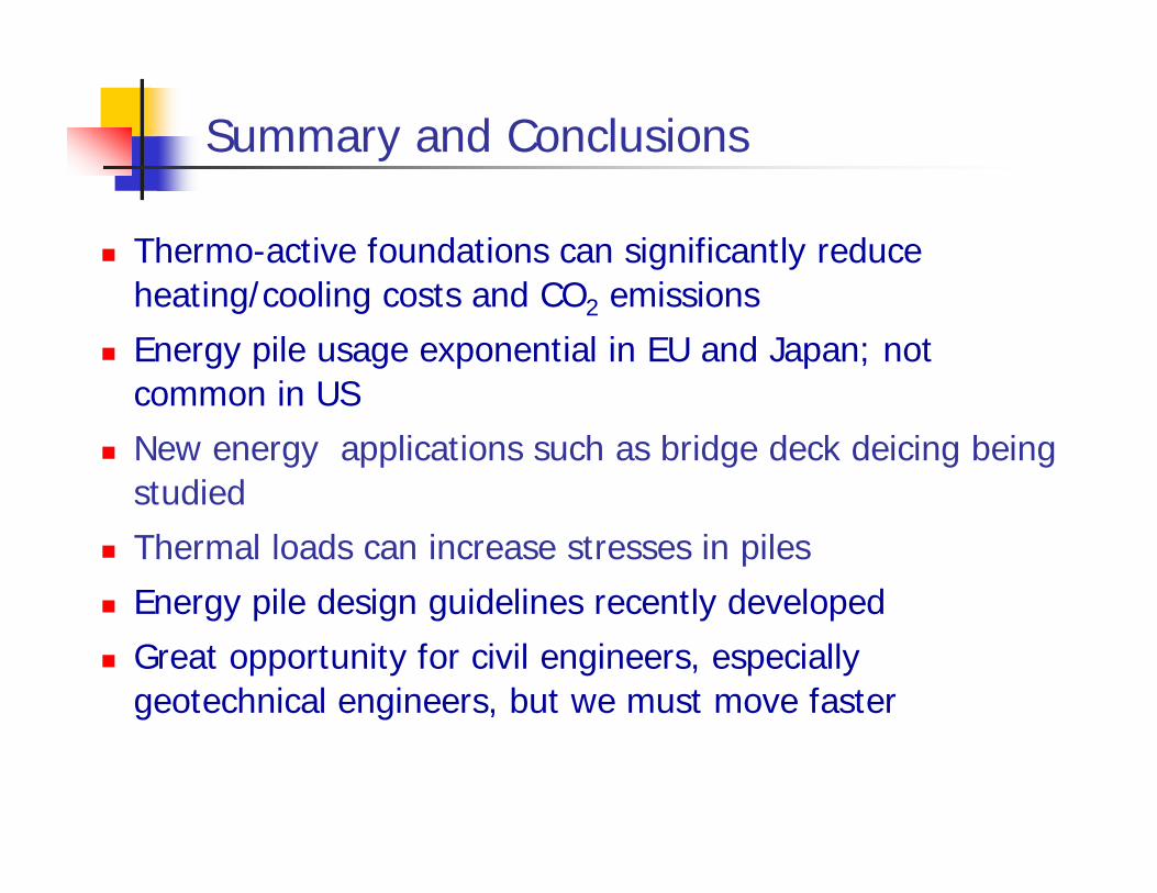
Summary and Conclusions
Thermo-active foundations can significantly reduce heating/cooling costs and CO2 emissions
Energy pile usage exponential in EU and Japan; not common in US
New energy applications such as bridge deck deicing being studied
Thermal loads can increase stresses in piles Energy pile design guidelines recently developed Great opportunity for civil engineers, especially
geotechnical engineers, but we must move faster
Thank You!
16th George F. Sowers SymposiumAtlanta, GA / May 7, 2013
C. Guney OlgunCivil & Environmental Engineering
Virginia [email protected] / www.olgun.cee.vt.edu