Embed Size (px)
Citation preview

www.advenergymat.de
Full paper
1900152 (1 of 7) © 2019 WILEY-VCH Verlag GmbH & Co. KGaA, Weinheim
Energy Harvesting-Storage Bracelet Incorporating Electrochemical Microsupercapacitors Self-Charged from a Single Hand Gesture
Steven L. Zhang, Qiu Jiang, Zhiyi Wu, Wenbo Ding, Lei Zhang, Husam N. Alshareef,* and Zhong Lin Wang*
DOI: 10.1002/aenm.201900152
research has been focused on harvesting the waste biomechanical motion by utilizing electromagnetic,[1–3] piezo-electric,[4,5] or triboelectric[6–9] effects. Utilizing triboelectric method, the tribo-electric nanogenerator has been invented, with its fundamental physics attributed to the Maxwell’s displacement current.[10] The triboelectric nanogenerator has been shown to effectively convert mechanical energies from our daily environment, such as from vibrations,[11–13] ocean waves,[14–16] and wind,[17–19] into electrical energy. However, the power output of all the mentioned harvesters is still low; thus, the electrical power is not enough to power some wearable electronic devices and sensors continuously. Thus, it is necessary to hybridize multiple gen-
erators together to provide higher voltage or current than indi-vidual generators. For example, hybridizing electromagnetic generator (EMG) and triboelectric nanogenerator (TENG) shows better performance because of a complimentary effect to effectively harvest energy.[20–23] However, the pulsed AC signal of both the EMG and TENG makes them unsuit-able for driving microelectronics directly. An energy storage device instead needs to be used to first store the energy gen-erated by the energy harvesters, and then deliver direct cur-rent to power the microelectronics. One good type of energy storage devices is the Li-ion battery; however, batteries have a limited cycle life time, and have known safety concerns due to toxic electrolyte and reactive Li metal. Meanwhile, another type of energy storage devices, electrochemical supercapaci-tors, can offer a higher power density and longer cycle life, making them a safe and excellent candidate to be integrated with energy harvesters to create a self-charging power unit to power microelectronics.
Different types of wearable energy harvesting devices have been fabricated previously.[24–26] Jiang et al. reported a single self-charging power unit, which integrates TENG device with solid-state microsupercapacitor, in order to simultaneously and effectively convert and store mechanical energy of human biomechanical motions into electrochemical energy.[27] Despite the advantages of the finalized device, the charging of the supercapacitor required a long time of human tapping motion, of roughly 30 min with continuous clapping to charge the
The development of wearable electronics and sensing networks has increased the demand for wearable power modules that have steady output, high energy density, and long cycle life. Current power modules, such as batteries, suffer from low energy density due to their limited storage capacity. One solution to avoid the issue is to build a hybrid device consisting of both energy harvesting elements that continuously harvest ambient mechanical energy, and electrochemical energy storage units to store the harvested energy. Here, a hybrid energy harvesting bracelet, which combines a dual electromagnetic and triboelectric nanogenerator to harvest wrist motions, is reported. The bracelet is able to charge the RuO2-based microsupercapacitor to 2 V with a single shake of human wrist, which allows the supercapacitor to power most electronic devices for minutes, such as a calculator, relative humidity, and temperature sensors.
S. L. Zhang, Prof. Z. Wu, Dr. W. Ding, L. Zhang, Prof. Z. L. WangSchool of Material Science and EngineeringGeorgia Institute of TechnologyAtlanta, GA 30332-0245, USE-mail: [email protected]. Q. Jiang, Prof. H. N. AlshareefMaterials Science and EngineeringKing Abdullah University of Science and Technology (KAUST)Thuwal 23955-6900, Saudi ArabiaE-mail: [email protected]. Z. Wu, Prof. Z. L. WangBeijing Institute of Nanoenergy and NanosystemsChinese Academy of SciencesBeijing 100085, China
The ORCID identification number(s) for the author(s) of this article can be found under https://doi.org/10.1002/aenm.201900152.
Energy Harvesting
1. Introduction
With an increasing development of wearable electronics and internet of things (IoT) sensor networks, extensive research has recently been focused on how one could provide power to these many sensors. One way involves utilizing a wearable solar cell, but then the device would only operate in pres-ence of light, and would not operate during night or during cloudy weather. Another possible solution is to scavenge waste biomechanical energy from human locomotion. Previously,
Adv. Energy Mater. 2019, 9, 1900152

www.advenergymat.dewww.advancedsciencenews.com
© 2019 WILEY-VCH Verlag GmbH & Co. KGaA, Weinheim1900152 (2 of 7)
supercapacitor to 0.6 V. Quan et al. reported a hybridized electromagnetic–triboelectric nanogenerator that is able to convert the biomechanical energy from the natural motions of the wearer’s wrist into electricity for sustainably powering an electronic watch.[28] However, the device was not truly a hybrid structure, as the TENG was mainly used to harvest energy from tapping motion, whereas the EMG was used to harvest energy from wrist shaking motion. Thus, a new device that can harvest energy by just wrist shaking, utilizing both the electromagnetic and triboelectric effects, is needed.
In this work, an energy harvesting bracelet is designed utilizing the cooperative operation of both EMG and TENG to deliver a high output performance. The harvested energy is then stored in an integrated electrochemical microsupercapac-itor that is attached onto the bracelet to power electronic devices and sensors. The charging of the electrochemical microsuper-capacitor could easily be charged to high voltages quickly with the user by engaging in daily activities, such as walking and running.
2. Results and Discussion
A schematic of the energy harvesting bracelet is shown in Figure 1a. The energy harvesting bracelet consists of two magnetic coils for EMG, two copper tapes attached on a shell structure for a TENG component, a magnetic mover with an electret polytetrafluorethylene (PTFE) material acting as a tribo-electrification layer inside the shell, and a power management
circuit containing a RuO2 supercapacitor in the connector region. The PTFE surface on the mover was treated with plasma to introduce surface roughness and improve contact and adhesion with the tube. A scanning electron microscopy (SEM) image shows the surface microstructures in Figure S1 in the Supporting Information. Compared to the PTFE that has not been treated with plasma, shown in Figure S2a in the Supporting Information, the surface roughness of the plasma treated PTFE is much larger. The increase in surface contact area, as a result of the surface microstructural modification by the plasma, is expected to improve performance of the triboelectric nanogenerator. This has been verified further in the manuscript. The fabrication process to make the bracelet is shown in Figure 1b, and is further explained in the Experi-mental Section.
The energy harvesting bracelet operates by shaking motion while engaging in physical activities, such as walking, running, etc. As the bracelet is shaken by wrist motion, the mag-netic mover would move from one end to the other, which could produce electricity by both the electromagnetic and the triboelectric effects. The mechanism for the electromagnetic generator is shown in Figure 1c, in which the all magnetic force lines pass through the magnetic mover. With increasing distance from the magnetic mover, the magnetic force lines are more and more sparse. The magnetic force lines inside and outside the magnetic mover, as the area I and II, respectively, in Figure 1c, are in opposite directions. So, in order to ensure the magnetic field acting on the coils is much stronger, which is needed to enhance the performance of the EMG component,
Adv. Energy Mater. 2019, 9, 1900152
Figure 1. The fabrication process and working mechanism of the hybrid energy harvesting bracelet. a) Schematic showing the hybrid energy harvesting bracelet with the magnetic mover element. b) Fabrication steps of the energy harvesting bracelet. c) Working mechanism of the electromagnetic generator. d) Working mechanism of the triboelectric nanogenerator, with I representing the current flow.
www.advenergymat.dewww.advancedsciencenews.com
© 2019 WILEY-VCH Verlag GmbH & Co. KGaA, Weinheim1900152 (3 of 7)
the displacement between the coil and the magnetic mover needs to be small. The mechanism for the triboelectric nanogenerator is shown in Figure 1d. As the magnetic mover object moves across from one end of the tube to the other, the PTFE that sur-rounds the magnetic mover would contact the PETG tube. By contact electrification, positive charges are created on the PETG tube’s surface, and negative charges are created on the PTFE’s surface. Since PTFE is an electret material, the negative charge would be stored on the PTFE’s surface. As the PTFE mover travels toward the copper electrode, positive charges would be induced onto the copper to neutralize the negatively charged PTFE in the system, and the charges would come from a ref-erence ground electrode. Also, as the PTFE mover becomes farther away from the copper electrode, the copper only expe-riences induction from the positively charged PETG tube, causing the electrode to be positively charged, and the charge would then flow from the copper electrode to the ground elec-trode. These steps are repeated as the magnetic mover element moves across the tube.
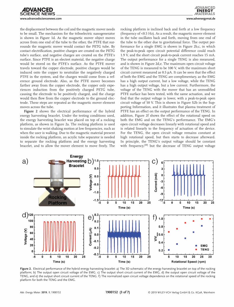
Figure 2 shows the electrical performance of the hybrid energy harvesting bracelet. Under the testing conditions used, the energy harvesting bracelet was placed on top of a rocking platform, as shown in Figure 2a. The rocking platform is used to simulate the wrist shaking motion at low frequencies, such as when the user is walking. Due to the magnetic material present inside the rocking platform, an acrylic tube separator is needed to separate the rocking platform and the energy harvesting bracelet, and to allow the mover element to move freely. The
rocking platform is inclined back and forth at a low frequency (frequency of <0.5 Hz). As a result, the magnetic mover element in the tube oscillates back and forth, moving from one end of the tube to the other due to gravitational force. The output per-formance for a single EMG is shown in Figure 2b,c, in which the peak-to-peak open circuit potential difference could reach 1.9 V, and the short circuit peak-to-peak current reaches 15 mA. The output performance for a single TENG is also measured, and is shown in Figure 2d,e. The maximum open circuit voltage of the TENG is measured to be 100 V, with the maximum short circuit current measured as 0.5 µA. It can be seen that the effect of both the EMG and the TENG are complimentary, as the EMG has a high output current, but a low voltage, while the TENG has a high output voltage, but a low current. Furthermore, the voltage of the TENG with the mover that has an unmodified PTFE surface has been tested, with the same actuation, and we find that the output voltage is lower, with a peak-to-peak open circuit voltage of 50 V. This is shown in Figure S2b in the Sup-porting Information, and it illustrates that plasma treatment of PTFE has an effect on the output performance of the TENG. In addition, Figure 2f shows the effect of the rotational speed on both the EMG and on the TENG’s performance. The EMG’s open circuit voltage decreases linearly with rotational speed and is related linearly to the frequency of actuation of the device. For the TENG, the open circuit voltage remains constant at high rotational speed, but then starts to decrease afterward. In principle, the TENG’s output voltage should be constant with frequency,[20] but the decrease of TENG output voltage
Adv. Energy Mater. 2019, 9, 1900152
Figure 2. Electrical performance of the hybrid energy harvesting bracelet: a) The 3D schematic of the energy harvesting bracelet on top of the rocking platform; b) The output open circuit voltage of the EMG. c) The output short circuit current of the EMG, d) the output open circuit voltage of the TENG, and e) the output short circuit current of the TENG. f) The normalized open circuit voltage dependence on the rotational speed of the rocking platform for both the TENG and the EMG.

www.advenergymat.dewww.advancedsciencenews.com
© 2019 WILEY-VCH Verlag GmbH & Co. KGaA, Weinheim1900152 (4 of 7)
at low frequency is due to the lack of sufficient kinetic energy to overcome the frictional force to slide fully down the tube. This shows that a lower open circuit voltage is obtained at low rotational frequency. The effect of voltage and current of the EMG and TENG elements has also been measured at higher frequencies (≈3 Hz) utilizing a linear motor setup, as shown in Figure S3 in the Supporting Information. Due to the higher working frequency, the voltage and current both increase for the EMG. In contrast, only the current increases for the TENG, whereas the voltage remains roughly constant.
To further enhance the performance, two generator ele-ments, EMG and TENG, were separately evaluated. Since there are two EMGs and two TENGs in the bracelet, it is necessary to evaluate the connection method to ensure that the maximum output is produced to the load. For the operation frequency of 0.5 Hz, the voltage decreased to 1.2 V when the EMGs are connected in parallel (Figure S4a,b, Supporting Information). This is less than the voltage required to power most electronic devices, but the current is significantly increased. In con-trast, when two EMGs were connected in series, the voltage increased up to 2.8 V (Figure S4c,d, Supporting Information), and the measured current also increased. This high voltage is large enough to power most devices, so connecting two EMGs in series has some advantage. Furthermore, the performance of two TENGs with different connections was also studied. When TENGs are connected in parallel, and rectified as shown in Figure S5a,b in the Supporting Information, the voltage decreased to around 35 V, but the current was largely enhanced to 0.4 µA, nearly double the value obtained when only one TENG is connected. When the TENGs are connected in series,
as shown in Figure S5c,d in the Supporting Information, the rectified voltage remains around 40 V, whereas the rectified current remains around 0.2 µA. Thus, we can conclude that TENGs connected in parallel give higher current to charge the supercapacitor.
Figure 3 shows the output power characteristics of the hybrid energy harvesting bracelet and the integrated RuO2 microsu-percapacitor. Figure 3a shows the measured power output as a function of load resistance for resistances of a single EMG. It can be seen that the EMG produces a peak power of 2.25 mW at a load resistance of 80 Ω. Figure 3b shows the power output of a single TENG as a function of load resistance. A single TENG produces a peak power of 70 µW using a load of 220 MΩ. The electrochemical performance of the RuO2 microsupercapacitor was evaluated by cyclic voltammetry (CV) at different scan rates. As shown in Figure 3c, CV curves show symmetric and rectan-gular curves in the 0.8 V window, indicating excellent rate per-formance. Figure 3d shows the charge–discharge curve of the supercapacitor. The curves are quite linear with no voltage drop in the window of 0–0.8 V, indicating good conductivity and cou-lombic efficiency of the supercapacitor. Furthermore, the areal capacitance was calculated from the charge–discharge curve, as shown in Figure S6 in the Supporting Information, in which the areal capacitance is 3 mF cm−2. Due to the anhydrous and compact nature of the sputtered RuO2, the areal capacitance is low compared with state-of-the-art microsupercapacitors[29–32] However, the critical parameter of microsupercapacitor for real integration is the self-discharge rate, RuO2 was chosen in this study mainly because of its slow self-discharge rate.[33] Figure 3e shows two EMGs connected in series, to obtain a
Adv. Energy Mater. 2019, 9, 1900152
Figure 3. The output power of the hybrid energy harvesting bracelet, and characteristics of the RuO2 microsupercapacitor. a) The peak power output of the EMG as a function of load resistance. b) The peak power output of the TENG as a function of load resistance. c) CV profiles of the RuO2 micro-supercapacitor. d) Charge–discharge curves of the RuO2 microsupercapacitor. e) Circuit diagram illustrating how the RuO2 microsupercapacitor is powered. f) The charging curve of two RuO2 supercapacitors connected in series by the hybrid energy harvesting bracelet by actuation at 0.5 Hz on the rocking platform.
www.advenergymat.dewww.advancedsciencenews.com
© 2019 WILEY-VCH Verlag GmbH & Co. KGaA, Weinheim1900152 (5 of 7)
higher output voltage, and two TENG connected in parallel to obtain a higher output current. Both the TENGs and the EMGs are then connected to a rectifying circuit that is able to convert the alternating current into direct current, so that the TENG and the EMG are able to charge the supercapacitor. The two RuO2 microsupercapacitors were connected in series, because the working voltage of each of the microsupercapacitors can only go up to 1 V, and 1 V is not enough voltage to power most electronics. Thus, connecting two in series could get the working voltage to 2 V, which is enough voltage to power most devices. The charging curve of two RuO2 microsupercapacitors connected in series is shown in Figure 3f under an actuation frequency of 0.5 Hz on the rotational stage. The microsuper-capacitors could be charged to 1.5 V by single actuation, and remains constant at this voltage with continuous actuation.
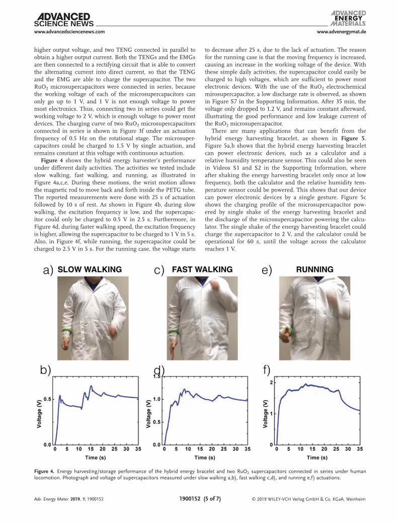
Figure 4 shows the hybrid energy harvester’s performance under different daily activities. The activities we tested include slow walking, fast walking, and running, as illustrated in Figure 4a,c,e. During these motions, the wrist motion allows the magnetic rod to move back and forth inside the PETG tube. The reported measurements were done with 25 s of actuation followed by 10 s of rest. As shown in Figure 4b, during slow walking, the excitation frequency is low, and the supercapac-itor could only be charged to 0.5 V in 2.5 s. Furthermore, in Figure 4d, during faster walking speed, the excitation frequency is higher, allowing the supercapacitor to be charged to 1 V in 5 s. Also, in Figure 4f, while running, the supercapacitor could be charged to 2.5 V in 5 s. For the running case, the voltage starts
to decrease after 25 s, due to the lack of actuation. The reason for the running case is that the moving frequency is increased, causing an increase in the working voltage of the device. With these simple daily activities, the supercapacitor could easily be charged to high voltages, which are sufficient to power most electronic devices. With the use of the RuO2 electrochemical mirosupercapacitor, a low discharge rate is observed, as shown in Figure S7 in the Supporting Information. After 35 min, the voltage only dropped to 1.2 V, and remains constant afterward, illustrating the good performance and low leakage current of the RuO2 microsupercapacitor.
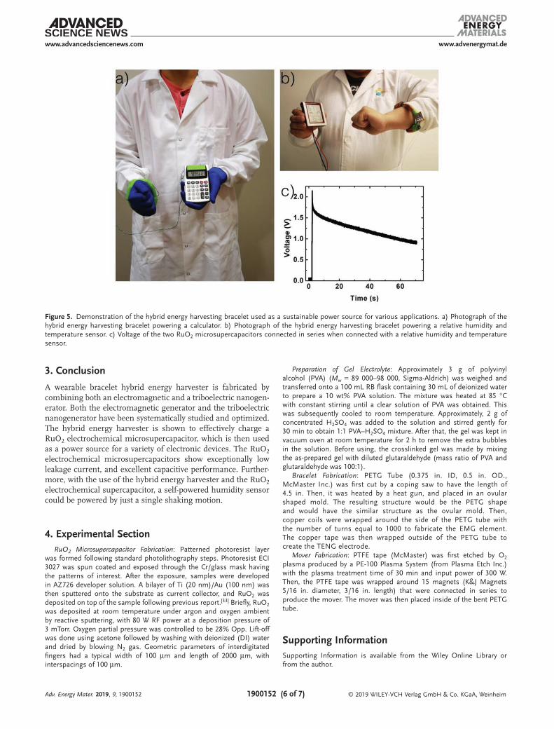
There are many applications that can benefit from the hybrid energy harvesting bracelet, as shown in Figure 5. Figure 5a,b shows that the hybrid energy harvesting bracelet can power electronic devices, such as a calculator and a relative humidity temperature sensor. This could also be seen in Videos S1 and S2 in the Supporting Information, where after shaking the energy harvesting bracelet only once at low frequency, both the calculator and the relative humidity tem-perature sensor could be powered. This shows that our device can power electronic devices by a single gesture. Figure 5c shows the charging profile of the microsupercapacitor pow-ered by single shake of the energy harvesting bracelet and the discharge of the microsupercapacitor powering the calcu-lator. The single shake of the energy harvesting bracelet could charge the supercapacitor to 2 V, and the calculator could be operational for 60 s, until the voltage across the calculator reaches 1 V.
Adv. Energy Mater. 2019, 9, 1900152
Figure 4. Energy harvesting/storage performance of the hybrid energy bracelet and two RuO2 supercapacitors connected in series under human locomotion. Photograph and voltage of supercapacitors measured under slow walking a,b), fast walking c,d), and running e,f) actuations.
www.advenergymat.dewww.advancedsciencenews.com
© 2019 WILEY-VCH Verlag GmbH & Co. KGaA, Weinheim1900152 (6 of 7)
3. Conclusion
A wearable bracelet hybrid energy harvester is fabricated by combining both an electromagnetic and a triboelectric nanogen-erator. Both the electromagnetic generator and the triboelectric nanogenerator have been systematically studied and optimized. The hybrid energy harvester is shown to effectively charge a RuO2 electrochemical microsupercapacitor, which is then used as a power source for a variety of electronic devices. The RuO2 electrochemical microsupercapacitors show exceptionally low leakage current, and excellent capacitive performance. Further-more, with the use of the hybrid energy harvester and the RuO2 electrochemical supercapacitor, a self-powered humidity sensor could be powered by just a single shaking motion.
4. Experimental SectionRuO2 Microsupercapacitor Fabrication: Patterned photoresist layer
was formed following standard photolithography steps. Photoresist ECI 3027 was spun coated and exposed through the Cr/glass mask having the patterns of interest. After the exposure, samples were developed in AZ726 developer solution. A bilayer of Ti (20 nm)/Au (100 nm) was then sputtered onto the substrate as current collector, and RuO2 was deposited on top of the sample following previous report.[33] Briefly, RuO2 was deposited at room temperature under argon and oxygen ambient by reactive sputtering, with 80 W RF power at a deposition pressure of 3 mTorr. Oxygen partial pressure was controlled to be 28% Opp. Lift-off was done using acetone followed by washing with deionized (DI) water and dried by blowing N2 gas. Geometric parameters of interdigitated fingers had a typical width of 100 µm and length of 2000 µm, with interspacings of 100 µm.
Preparation of Gel Electrolyte: Approximately 3 g of polyvinyl alcohol (PVA) (Mw = 89 000–98 000, Sigma-Aldrich) was weighed and transferred onto a 100 mL RB flask containing 30 mL of deionized water to prepare a 10 wt% PVA solution. The mixture was heated at 85 °C with constant stirring until a clear solution of PVA was obtained. This was subsequently cooled to room temperature. Approximately, 2 g of concentrated H2SO4 was added to the solution and stirred gently for 30 min to obtain 1:1 PVA–H2SO4 mixture. After that, the gel was kept in vacuum oven at room temperature for 2 h to remove the extra bubbles in the solution. Before using, the crosslinked gel was made by mixing the as-prepared gel with diluted glutaraldehyde (mass ratio of PVA and glutaraldehyde was 100:1).
Bracelet Fabrication: PETG Tube (0.375 in. ID, 0.5 in. OD., McMaster Inc.) was first cut by a coping saw to have the length of 4.5 in. Then, it was heated by a heat gun, and placed in an ovular shaped mold. The resulting structure would be the PETG shape and would have the similar structure as the ovular mold. Then, copper coils were wrapped around the side of the PETG tube with the number of turns equal to 1000 to fabricate the EMG element. The copper tape was then wrapped outside of the PETG tube to create the TENG electrode.
Mover Fabrication: PTFE tape (McMaster) was first etched by O2 plasma produced by a PE-100 Plasma System (from Plasma Etch Inc.) with the plasma treatment time of 30 min and input power of 300 W. Then, the PTFE tape was wrapped around 15 magnets (K&J Magnets 5/16 in. diameter, 3/16 in. length) that were connected in series to produce the mover. The mover was then placed inside of the bent PETG tube.
Supporting InformationSupporting Information is available from the Wiley Online Library or from the author.
Adv. Energy Mater. 2019, 9, 1900152
Figure 5. Demonstration of the hybrid energy harvesting bracelet used as a sustainable power source for various applications. a) Photograph of the hybrid energy harvesting bracelet powering a calculator. b) Photograph of the hybrid energy harvesting bracelet powering a relative humidity and temperature sensor. c) Voltage of the two RuO2 microsupercapacitors connected in series when connected with a relative humidity and temperature sensor.

www.advenergymat.dewww.advancedsciencenews.com
© 2019 WILEY-VCH Verlag GmbH & Co. KGaA, Weinheim1900152 (7 of 7)
AcknowledgementsS.L.Z., Q.J., and Z.W. contributed equally to this work. Research reported in this publication was supported by King Abdullah University of Science and Technology (KAUST) under the Sensors Initiative (Grant # REP/1/2709-01-01).
Conflict of InterestThe authors declare no conflict of interest.
Received: January 15, 2019Revised: March 4, 2019
Published online: March 25, 2019
[1] E. Bouendeu, A. Greiner, P. J. Smith, J. G. Korvink, IEEE Sens. J. 2011, 11, 107.
[2] C. Wei, X. Jing, Renewable Sustainable Energy Rev. 2017, 74, 1.[3] S. D. Moss, O. R. Payne, G. A. Hart, C. Ung, Smart Mater. Struct.
2015, 24, 023001.[4] H. S. Kim, J.-H. Kim, J. Kim, Int. J. Precis. Eng. Manuf. 2011, 12, 1129.[5] B. Kumar, S.-W. Kim, Nano Energy 2012, 1, 342.[6] G. Zhu, B. Peng, J. Chen, Q. Jing, Z. L. Wang, Nano Energy 2015, 14,
126.[7] Z. L. Wang, J. Chen, L. Lin, Energy Environ. Sci. 2015, 8, 2250.[8] Z. L. Wang, Faraday Discuss. 2015, 176, 447.[9] F.-R. Fan, Z.-Q. Tian, Z. L. Wang, Nano Energy 2012, 1, 328.
[10] Z. L. Wang, Mater. Today 2017, 20, 74.[11] W. Yang, J. Chen, Q. Jing, J. Yang, X. Wen, Y. Su, G. Zhu, P. Bai,
Z. L. Wang, Adv. Funct. Mater. 2014, 24, 4090.[12] W. Tang, T. Jiang, F. R. Fan, A. F. Yu, C. Zhang, X. Cao, Z. L. Wang,
Adv. Funct. Mater. 2015, 25, 3718.[13] N. Arora, S. L. Zhang, F. Shahmiri, D. Osorio, Y.-C. Wang,
M. Gupta, Z. Wang, T. Starner, Z. L. Wang, G. D. Abowd, Proc. ACM Interact., Mobile, Wearable Ubiquitous Technol. 2018, 2, 1.
[14] S. L. Zhang, M. Xu, C. Zhang, Y.-C. Wang, H. Zou, X. He, Z. Wang, Z. L. Wang, Nano Energy 2018, 48, 421.
[15] Z. L. Wang, T. Jiang, L. Xu, Nano Energy 2017, 39, 9.[16] J. Chen, J. Yang, Z. Li, X. Fan, Y. Zi, Q. Jing, H. Guo, Z. Wen,
K. C. Pradel, S. Niu, ACS Nano 2015, 9, 3324.[17] Y. Yang, G. Zhu, H. Zhang, J. Chen, X. Zhong, Z.-H. Lin, Y. Su,
P. Bai, X. Wen, Z. L. Wang, ACS Nano 2013, 7, 9461.[18] M. Xu, P. Wang, Y. C. Wang, S. L. Zhang, A. C. Wang, C. Zhang,
Z. Wang, X. Pan, Z. L. Wang, Adv. Energy Mater. 2018, 8, 1702432.[19] M. Xu, Y.-C. Wang, S. L. Zhang, W. Ding, J. Cheng, X. He, P. Zhang,
Z. Wang, X. Pan, Z. L. Wang, Extreme Mech. Lett. 2017, 15, 122.[20] Y. Zi, H. Guo, Z. Wen, M.-H. Yeh, C. Hu, Z. L. Wang, ACS Nano
2016, 10, 4797.[21] Z. Wen, H. Guo, Y. Zi, M.-H. Yeh, X. Wang, J. Deng, J. Wang, S. Li,
C. Hu, L. Zhu, ACS Nano 2016, 10, 6526.[22] X. Zhong, Y. Yang, X. Wang, Z. L. Wang, Nano Energy 2015, 13, 771.[23] B. Zhang, J. Chen, L. Jin, W. Deng, L. Zhang, H. Zhang, M. Zhu,
W. Yang, Z. L. Wang, ACS Nano 2016, 10, 6241.[24] S. L. Zhang, Y. C. Lai, X. He, R. Liu, Y. Zi, Z. L. Wang, Adv. Funct.
Mater. 2017, 27, 1606695.[25] Y. C. Lai, J. Deng, S. L. Zhang, S. Niu, H. Guo, Z. L. Wang,
Adv. Funct. Mater. 2017, 27, 1604462.[26] Y. C. Lai, J. Deng, S. Niu, W. Peng, C. Wu, R. Liu, Z. Wen, Z. L. Wang,
Adv. Mater. 2016, 28, 10024.[27] Q. Jiang, C. Wu, Z. Wang, A. C. Wang, J.-H. He, Z. L. Wang,
H. N. Alshareef, Nano Energy 2018, 45, 266.[28] T. Quan, X. Wang, Z. L. Wang, Y. Yang, ACS Nano 2015, 9, 12301.[29] D. Pech, M. Brunet, P.-L. Taberna, P. Simon, N. Fabre,
F. Mesnilgrente, V. Conédéra, H. Durou, J. Power Sources 2010, 195, 1266.
[30] J. Chmiola, C. Largeot, P.-L. Taberna, P. Simon, Y. Gogotsi, Science 2010, 328, 480.
[31] D. Pech, M. Brunet, H. Durou, P. Huang, V. Mochalin, Y. Gogotsi, P.-L. Taberna, P. Simon, Nat. Nanotechnol. 2010, 5, 651.
[32] J. Lin, C. Zhang, Z. Yan, Y. Zhu, Z. Peng, R. H. Hauge, D. Natelson, J. M. Tour, Nano Lett. 2013, 13, 72.
[33] M. K. Hota, Q. Jiang, Y. Mashraei, K. N. Salama, H. N. Alshareef, Adv. Electron. Mater. 2017, 3, 1700185.
Adv. Energy Mater. 2019, 9, 1900152