Embed Size (px)
Citation preview
ENERGY HARVESTING IN A ROTATING TIRE
ENHANCING NON-LINEAR VIBRATION
(非線形振動を励起させることによる回転する
タイヤ内でのエナジーハーべスティング)
張 云順
2
Contents
ABSTRACT ............................................................................................................................................ 4
NOMENCLATURE AND ABBREVIATIONS .................................................................................... 6
ACKNOWLEDGEMENTS ................................................................................................................. 10
INTRODUCTION ................................................................................................................................ 12
1.1 Background ................................................................................................................................. 12
1.2 Tire Rotating Energy Harvesting ................................................................................................. 14
1.2.1 Piezoelectric .......................................................................................................................... 14
1.2.2 Electromagnetic ..................................................................................................................... 16
1.2.3 Electrostatic ........................................................................................................................... 17
1.3 Broadening Frequency Bandwidth .............................................................................................. 18
1.3.1 Linear Resonant Frequency Tuning ....................................................................................... 18
1.3.2 Multi-Frequency Converter Array ......................................................................................... 19
1.3.3 Frequency-up Conversion ...................................................................................................... 19
1.3.4 Nonlinear Approach ............................................................................................................... 20
1.4 Objective and Structure ............................................................................................................... 22
ENERGY HARVESTING FROM NONLINEAR VIBRATION...................................................... 25
2.1 Nonlinear Systems ....................................................................................................................... 25
2.1.1 Monostable Energy Harvester ............................................................................................... 25
2.1.2 Bistable Energy Harvester ..................................................................................................... 30
2.2 Stochastic Resonance .................................................................................................................. 31
2.3 Challenges on Rotational Energy Harvester ................................................................................ 35
METHODOLOGY FOR ROTATION-INDUCED ENERGY HARVESTING............................... 38
3.1 Bistable System under Rotational Circumstances ....................................................................... 38
3.2 Modelling for Simulated Tire Rotation ....................................................................................... 39
3.2.1 Mathematical Analysis .......................................................................................................... 39
3.2.2 Stochastic Resonance Frequency ........................................................................................... 43
3.3 Modelling for Real-World Tire Rotation ..................................................................................... 46
3.3.1 Modified Stochastic Resonance Frequency ........................................................................... 46
3.3.2 On-Road Noise Measurement................................................................................................ 49
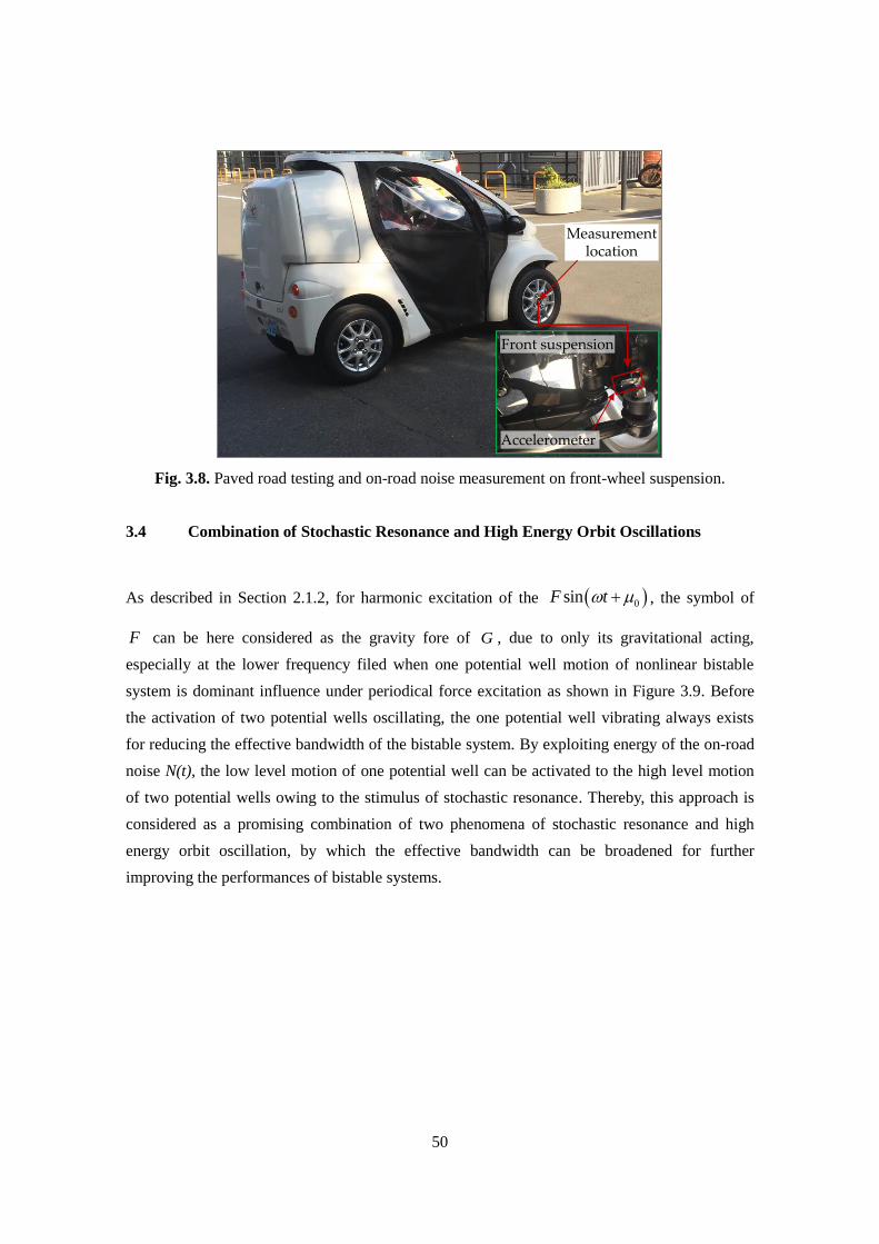
3.4 Combination of Stochastic Resonance and High Energy Orbit Oscillations ............................... 50
3.5 Stability of High Energy Orbit Oscillating Using Centrifugal Force .......................................... 51
3
NUMERICAL ANALYSIS ................................................................................................................... 60
4.1 Responses under Stochastic Resonance....................................................................................... 60
4.1.1 Responses under Simulating Conditions ............................................................................... 60
4.1.2 Responses under Measured on-Road Noise........................................................................... 63
4.2 Bandwidth Broadening by Combining Stochastic Resonance and High Energy Orbit ............... 65
4.3 Bandwidth Broadening by Using Centrifugal Force ................................................................... 66
4.3.1 Hardening Stiffness Tuning ................................................................................................... 66
4.3.2 Softening Stiffness Tuning .................................................................................................... 71
4.3.3 Performance of Varying Centrifugal Distance ....................................................................... 72
EXPERIMENTAL STUDY ................................................................................................................. 80
5.1 Laboratory Experiment ................................................................................................................ 80
5.1.1 Laboratory Apparatus ............................................................................................................ 80
5.1.2 Responses Performance ......................................................................................................... 82
5.1.3 Energy Harvesting Performance ............................................................................................ 88
5.1.4 Validation of Combining Stochastic Resonance and High Energy Orbit Oscillations ........... 96
5.2 Actual-Vehicle Experiment ......................................................................................................... 98
5.2.1 Apparatus for on-Road Experiment ....................................................................................... 98
5.2.2 Enhanced Energy Harvesting .............................................................................................. 103
5.2.3 Further Improvement ........................................................................................................... 105
DISCUSSIONS ................................................................................................................................... 111
6.1 Coexistence of Three Nonlinear Oscillating Phenomena .......................................................... 111
6.2 Effect of Noise Intensity on Response....................................................................................... 115
6.3 Rectifier Circuit for Tire-Induced Energy Harvesting ............................................................... 117
6.4 Comparison with Other Energy Harvesting Strategies .............................................................. 119
CONCLUSIONS ................................................................................................................................. 123
REFERENCES ................................................................................................................................... 126
LIST OF PUBLICATIONS ................................................................................................................ 134
4
Abstract
A model for energy harvesting from a rotating automotive tire is exploited by application of the
principle of stochastic resonance to enhance energy harvesting efficiency. A bistable response
characteristic can be obtained by recourse to a small harvester comprising a magnetically
repellant configuration, in which an instrumented cantilever beam can flip between two physical
response states, when suitably excited by the rotation of a car wheel into which it is fitted. The
rotation of the wheel creates a periodic modulation which enables stochastic resonance to take
place, and as a consequence of this for energy to be harvested from road noise transmitted
through the tire. A concisely mathematical model of the harvesting system is presented based on
a series of experimental tests, and it indicates that a ten-fold increase in harvested energy is
feasible over a comparable monostable case. In practice, the suggested application for this
harvester is to provide electrical power for a tire pressure monitoring system.
For the case of actual wheel rotation, the present study investigates the effectiveness of a
piezoelectric energy harvester, with the application of stochastic resonance to optimize the
efficiency of energy harvesting. It is hypothesized that the energy harvester is subjected to
on-road noise as ambient excitations while the wheel rotates at variable speeds, and meanwhile
a tangentially acting gravity force as a periodic modulation force that can stimulate stochastic
resonance. For a laboratory experiment, the energy harvester was miniaturized with a bistable
cantilever structure, and the on-road noise was measured for the implementation of a vibrator. A
validation experiment revealed that the energy harvesting performance of system was improved
to capture powers, which were approximately 12 times that of the captured under only on-road
excitation and 50 times that of the captured under only the periodic gravity force.
Moreover, through the investigation of up-sweep excitations with an increasing rotational
frequency, it is confirmed that stochastic resonance is effective in improving the performance of
the energy harvester, with a certain bandwidth of vehicle speeds. Furthermore, it is found that
the ability of the energy harvesting can be enhanced over a wider rotational frequency under
considering the combination of stochastic resonance and the high energy orbit phenomena of the
bistable systems. An actual-vehicle experiment validates that the prototype harvester using
stochastic resonance is capable of improving power generation performance for practical tire
application.
On the other hand, nonlinear energy harvesters have already been exhibited to draw energy
from ambient vibration owing to their particular dynamic characteristics, in which are feasible
to desirable responses for broadband excitations of bistable and monostable systems. However,
due to coexistence of the lower energy orbit, it is still a challenging topic that is how to achieve

5
the stability of the high energy orbit oscillating to improve the valid broadband of the
excitations. This study also focuses on proposing a stiffness tunable energy harvester for
rotational applications.
As the rotationally angular velocity gradually increases, the tensile stress to the cantilever
beam is also self-adjusted with the increscent centrifugal force, causing the potential barriers of
bistable type to become shallow, so that the cantilever beam has the ability to maintain the high
energy orbit motion from bistable hardening type to monostable hardening behavior. From the
implemented results, the valid bandwidth of angular frequency can be improved from 26 rad/s–
132 rad/s to 15 rad/s–215 rad/s, under the case of the effect of centrifugal force on nonlinear
vibrating behavior. In an actual-vehicle experiment, it is simultaneously demonstrated that the
centrifugal force can significantly promote the performance of nonlinear energy harvesters in
the tire applications.

6
Nomenclature and Abbreviations
B Magnetic flux density
C ,PC Electrostatic capacitance
D Power intensity of ambient vibration
iD Amplitude of diode
E ,KE Kinetic energy
bE Activation energy
1E , 2E , 3E , tE Dissipated energy
E Young’s modulus
F Amplitude of harmonic force
RF , tF Resultant restoring force
MF Repulsive magnetic force
HF Tangential component of magnetic force
MF Nonlinear spring force
cF Centrifugal force
tF Tangential centrifugal force
G Gravity
G Transfer function
H Centrifugal distance
I ,bI Equivalently action
I Moment of inertia
L Length
M Particle mass
Mf, Mc Magnetization amplitude
Mfx, Mcx Magnetization amplitude in x direction
Mfy, Mcy Magnetization amplitude in y direction
N Ambient noise
P Instantaneous power
P Dynamic force
7
R Total resistance
opR Internal impedance of transducer
LR External load resistance
SR Internal impedance of sensor
cT Centripetal centrifugal force
U ,dU Dimensional displacement amplitude
0U ,MU , 0U Potential energy
V Voltage response
Gravity acceleration
a Linear coefficient
a Acceleration
a , a Negative and positive equivalent linear stiffness
b Nonlinear coefficient
nb Amplitude of the first sampling point
n pb Amplitude of the last sampling point
c Damping coefficient
mc Mechanical damping coefficient
ec Electrical damping coefficient
d Distance between two magnets
( )f t Linear amplification
Hf Resultant force
g Gravity acceleration
( )g t Linear attenuation
i Direction of current
j Imaginative symbol
j Steady-state current
k Spring constant
k Nonlinear spring coefficient
k Equivalent stiffness coefficient

8
Bk T Power intensity of ambient vibration
l Center axis of vibration
l Centrifugal distance
m Seismic mass
mc Magnetic dipole moment vector
0n Population inside initial domain
n Number of the first counting point
1p , 2p , 3p Average generated power
0p , p Stationary probability density
p Number of the last counting point
r Radius
t Real-time
u Relative displacement
u Steady state solution
u Velocity of steady state solution
u Velocity of steady state solution
v , v Velocity
Sv Tangential speed
cv Centripetal speed
v Volume of the magnet
w Transverse displacement
Tx , x ,0x Relative displacement
cy Centripetal displacement
1 Power intensity of ambient vibration
, Jump down frequency
Replacement symbol
Deflection angle
Electromechanical coupling coefficient
Angular velocity of harmonic force

9
b Boundary frequency
cc Determination frequency
n ,0 Resonance of nonlinear system
SR , SR Frequency of stochastic resonance
d Positive solution of jump-down frequency
Replacement symbol
, , Escape rate
Permeability of free space
Static linear shape
Replacement symbol
0 Initial phase angle
Total experiment time
U Activation energy
Damping coefficient
Ambient noise

10
Acknowledgements
I sincerely appreciate to my supervisor Dr. Kimihiko Nakano, Associate Professor in The
University of Tokyo for his helpful guidance, positive encouragement, and academic suggestion
over the past three years. His enthusiasm and attitude to details will continue to influence my
academic career in the future.
I greatly thank Professor Yoshihiro Suda, Professor Shinichi Warisawa, Professor Beom Joon
Kim, and Associate Professor Takeshi Oishi. As referees of my dissertation, all of their valuable
comments and constructive suggestions are helpful to complete my research and improve the
dissertation.
I deeply wish to thank Dr. Rencheng Zheng, the Project Associate Professor of the K. Nakano
Laboratory. He strenuously supported me in my experiments and enthusiastically helped me so
much not only in my research but also in my daily life. I also want to convey my sincere thanks
to Professor Matthew P. Cartmell, University of Strathclyde, for his valuable assistance and
productive discussions.
I appreciate Dr. Tsutomu Kaizuka, the Research Associate of the K. Nakano Laboratory, and
he gave me much advice about experimental design and helped me to carry out the experiments.
I also appreciate Dr. Keisuke Shimono, Dr. Kenji Ejiri, the previous Project Researchers of K.
Nakano Laboratory, and Dr. Dongxu Su, the Degree Recipient of K. Nakano Laboratory for
their helpfully technical assistant.
I express my gratitude to the staffs of the Central Workshop of the Institute of Industrial
Science, The University of Tokyo, who are Mr. Yoshihiro Itakura, Mr. Kentarou Shikada, and
Mr. Etsuo Yatagai. Thanks to them for the important suggestions and assistance during the
process of the equipment manufacturing.
I also would like to express my gratitude to Ms. Atsuko Hasegawa, the Secretary of the K.
Nakano Laboratory, for his warmly encouragement and care on my daily life as well as the
research activities.
Meanwhile, I want to thank to Mr. Bo Yang, Mr. Zheng Wang, Mr. Antonin Joly, and all the
other members of the K. Nakano Laboratory, they gave me their help with their kindness in my
research and daily life.
Last but not least, I can never forget the support from my parents and two sisters during this
unforgettable period of my study abroad. I appreciate them from the bottom of my heart.
February 6, 2017
Yunshun Zhang

11
Chapter 1
Introduction
12
1. Introduction
1.1 Background
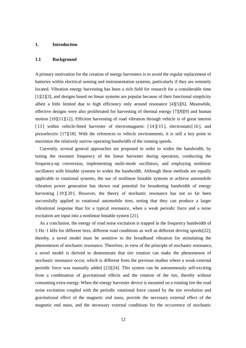
A primary motivation for the creation of energy harvesters is to avoid the regular replacement of
batteries within electrical sensing and instrumentation systems, particularly if they are remotely
located. Vibration energy harvesting has been a rich field for research for a considerable time
[1][2][3], and designs based on linear systems are popular because of their functional simplicity
albeit a little limited due to high efficiency only around resonance [4][5][6]. Meanwhile,
effective designs were also proliferated for harvesting of thermal energy [7][8][9] and human
motion [10][11][12]. Efficient harvesting of road vibration through vehicle is of great interest
[ 13 ] within vehicle-fitted harvester of electromagnetic [ 14 ][ 15 ], electrostatic[ 16 ], and
piezoelectric [17][18]. With the references to vehicle environments, it is still a key point to
maximize the relatively narrow operating bandwidth of the running speeds.
Currently, several general approaches are proposed in order to widen the bandwidth, by
tuning the resonant frequency of the linear harvester during operation, conducting the
frequency-up conversion, implementing multi-mode oscillators, and employing nonlinear
oscillators with bistable systems to widen the bandwidth. Although these methods are equally
applicable to rotational systems, the use of nonlinear bistable systems to achieve automobile
vibration power generation has shown real potential for broadening bandwidth of energy
harvesting [19 ][20 ]. However, the theory of stochastic resonance has not so far been
successfully applied to rotational automobile tires, noting that they can produce a larger
vibrational response than for a typical resonance, when a weak periodic force and a noise
excitation are input into a nonlinear bistable system [21].
As a conclusion, the energy of road noise excitation is trapped in the frequency bandwidth of
5 Hz–1 kHz for different tires, different road conditions as well as different driving speeds[22];
thereby, a novel model must be sensitive to the broadband vibration for stimulating the
phenomenon of stochastic resonance. Therefore, in view of the principle of stochastic resonance,
a novel model is derived to demonstrate that tire rotation can make the phenomenon of
stochastic resonance occur, which is different from the previous studies where a weak external
periodic force was manually added [23][24]. This system can be autonomously self-exciting
from a combination of gravitational effects and the rotation of the tire, thereby without
consuming extra energy. When the energy harvester device is mounted on a rotating tire the road
noise excitation coupled with the periodic rotational force caused by the tire revolution and
gravitational effect of the magnetic end mass, provide the necessary external effect of the
magnetic end mass, and the necessary external conditions for the occurrence of stochastic
13
resonance. Besides that this fabricated energy harvester has dimensions much smaller than
applied in previous studies, enabling it to be possibly quite widely applied in the automotive
field. Moreover, instead of a typically low frequency of 3 Hz as encountered for stochastic
resonance, this study shows that power harvesting can be enhanced by stochastic resonance at a
higher frequency of 15.6 Hz.
Meanwhile, stochastic resonance as a physical phenomenon has recently been proposed to
explain the periodicity of Earth’s glaciation, where the output response can be greatly amplified
with a certain probability by adding noise to a weak periodic signal [25]. In recent years, this
phenomenon has attracted considerable attention for information transmission and detection
[ 26 ][ 27 ][ 28 ][ 29 ], biological neuro analysis [ 30 ][ 31 ][ 32 ][ 33 ], and image processing
[34][35][36][37]. In the mechanical engineering field, it has been theoretically investigated
whether stochastic resonance can be applied to improve the efficiency of energy harvesting [38].
Consequently, an experimental study has realized the one-degree-of-freedom behavior of
stochastic resonance in a bistable vibrating energy harvester [24][39]. Nevertheless, in the
rotational environment of an automobile wheel, such behavior coexists with the
two-degree-of-freedom motion of the wheel rotation and vibration.
In this study, ideal white noise and a periodic force were employed to simulate rotational
wheel motion, and the energy harvesting efficiency is improved by the realization of stochastic
resonance. By application of the on-road noise measured for low-speed automobile wheels, a
mathematical model of vibration energy harvesting is presented for the simulation analysis of
stochastic resonance. Furthermore, a macro-scale energy harvester is fabricated, and only
displacement response is studied to know its dynamic performance. However, it is still unclear
for their harvesting effectiveness in a real-world environment.
Therefore, considering on-road noise and periodic acceleration by gravity for vehicle
traveling on a paved road, the present study also focuses on the effectiveness testing of a
piezoelectric energy harvester on vehicle tires using stochastic resonance, and the energy
harvesting characteristics are comprehensively investigated through simulation and laboratory
experimental analyses. It shows that the appearance of stochastic resonance is not limited to a
constant rotation frequency but can be maintained under varying frequencies, indicating that
more energy can be harvested with a bandwidth for rotational systems. Moreover, the bandwidth
can be further broadened by combining the stochastic resonance and high energy orbit
oscillation.
The nonlinearity of the system that can improve the performance of the energy harvester over
a wider bandwidth is presented for enhancing energy harvesting over that of the conventional
linear energy harvester [40][41][42]. It is classified into bistable [43][44], monostable
hardening , and monostable softening cases [45][46]. Through adjusting the parameters of the
14
above nonlinear systems, the systems can appear an enhanced high-energy orbit motion over a
certain frequency range. Meanwhile, because of the existence of unstable and low-energy orbits,
it is necessary to stabilize the high-energy orbit all the time by the adjustability of system
parameters, with a widely variable frequency of environment excitations.
A nonlinear energy harvesting model that is considered to apply to rotational environments,
which is different from the previous researches of this study that the centrifugal force is not
exploited. The linear stiffness of this system can be tuned to achieve the sustained high-energy
orbit oscillating by stimulating the system of bistable into monostable hardening type under
considering the increasingly centrifugal force effect. In comparison to a passive self-tuning
linear and pendulum energy harvesters adopted to rotational motion [47][48][49], the apparent
advantage in the nonlinear section is specifically analyzed in this study.
1.2 Tire Rotating Energy Harvesting
With the increasing requirements of advanced driving assistance systems, researchers have
developed a tire-pressure monitoring system that can provide the driver with the tire condition
via wireless transmission [50][51][52]. However, because it is inconvenient to replace or
recharge the batteries of a monitoring system, there is a desire to establish an effective energy
harvesting system [53].
1.2.1 Piezoelectric
Several researchers have attempted to exploit the piezoelectric energy harvesters for rotating
environments. Specifically, a linearly piezoelectric energy harvester using a cantilever beam has
been proposed, where the centrifugal force is used to stimulate the natural frequency of the
energy harvester system matching the rotational frequency [54]. A linear MEMS energy
harvester using tire shock excitations was proposed for automotive applications; however, it can
extract more energy only in the case of high-speed driving, and the energy harvesting efficiency
depends on the concave-convex condition of the road surface [55]. A nanogenerator layer was
attached on the inner surface of the tire, and the energy was harvested by the bending of the
piezoelectric film; however, the energy harvesting performance was investigated using a bicycle tire
instead of a real vehicle tire also it would cost too high for fabricating or replacing the piezoelectric
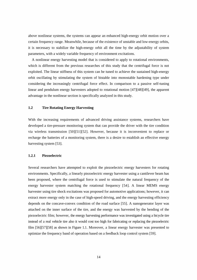
film [56][57][58] as shown in Figure 1.1. Moreover, a linear energy harvester was presented to
optimize the frequency band of operation based on a feedback loop control system [59].
15
Fig. 1.1. Tire energy harvesting using the bend deformation during vehicle movement.
Nonlinear systems have a small structure, which can improve the performance over a wider
bandwidth for harvesting more energy compared with a conventional linear system; therefore,
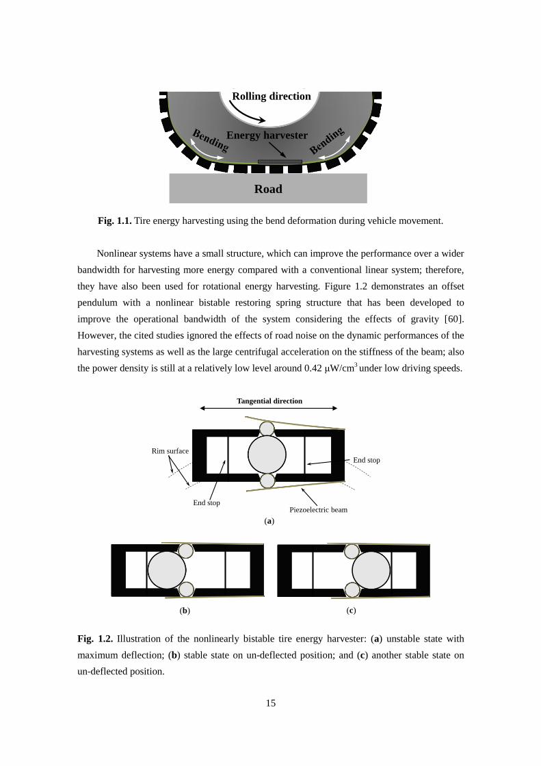
they have also been used for rotational energy harvesting. Figure 1.2 demonstrates an offset
pendulum with a nonlinear bistable restoring spring structure that has been developed to
improve the operational bandwidth of the system considering the effects of gravity [60].
However, the cited studies ignored the effects of road noise on the dynamic performances of the
harvesting systems as well as the large centrifugal acceleration on the stiffness of the beam; also
the power density is still at a relatively low level around 0.42 μW/cm3 under low driving speeds.
Fig. 1.2. Illustration of the nonlinearly bistable tire energy harvester: (a) unstable state with
maximum deflection; (b) stable state on un-deflected position; and (c) another stable state on
un-deflected position.
Road
Energy harvester
Rolling direction
Tangential direction
End stop
End stop
Piezoelectric beam
Rim surface
(a)
(b) (c)
16
1.2.2 Electromagnetic
Electromagnetic as a conventional approach which makes use of the relative motion between
magnets and coils, has been investigated by many researchers [61][62]. The magnets often
linearly or rotationally move through the stationary coils, which is different from the above
introduced piezoelectric energy harvesters that often take the form of cantilevers. One approach
is to utilize inertial type, using which a levitated magnet is urged past the fixed coil among the
energy harvester that is mounted on the tire wheel as a result of tire contact with road surface
[63]. The advantages of this type of energy harvesters are its design simplicity and it is easy to
parametrically determine it in such a Watt that its resonance frequency matches the frequency of
the external excitation [64].
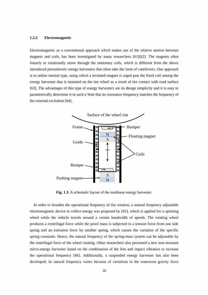
Fig. 1.3. A schematic layout of the nonlinear energy harvester.
In order to broaden the operational frequency of tire rotation, a natural frequency adjustable
electromagnetic device to collect energy was proposed by [65], which is applied for a spinning
wheel while the vehicle travels around a certain bandwidth of speeds. The rotating wheel
produces a centrifugal force while the proof mass is subjected to a tension force from one side
spring and an extrusion force by another spring, which causes the variation of the specific
spring constants. Hence, the natural frequency of the spring-mass system can be adjustable by
the centrifugal force of the wheel rotating. Other researchers also presented a new non-resonant
micro-energy harvester based on the combination of the free and impact vibration to increase
the operational frequency [66]. Additionally, a suspended energy harvester has also been
developed; its natural frequency varies because of variations in the transverse gravity force
N
S
N
S
Bumper
Floating magnet
Pushing magnet
Frame
Bumper
Guide
Coils
Surface of the wheel rim
17
during plate rotation, then the harvester mean power of the harvester was improved to 30 μW
with extrapolated power density of 0.94 μW/cm3 under the condition of low-frequency rotating
[67].
Furthermore, a nonlinearity system is presented and its configuration is shown in Figure 1.3.
The energy harvester is mounted to the surface of the wheel rim, it is subjected to the radial
acceleration which resulted from centrifugal force, contact zone and changes its shape, and the
preload from the pushing magnet. An analysis of different nonlinearities of the system at
different vehicle speeds and a study on the combined effect of softening and hardening behavior
of the device are performed and discussed [68].
1.2.3 Electrostatic
The electrostatic energy harvester captures power by the variable capacitor while it is driven by
the environmentally mechanical vibrations. As the capacitance decreases, the charge will move
from the capacitor to a storage device or to the external resistance load resulting in the
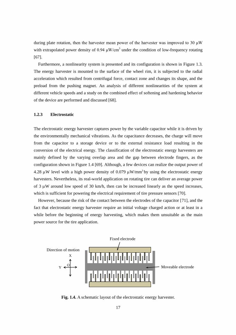
conversion of the electrical energy. The classification of the electrostatic energy harvesters are
mainly defined by the varying overlap area and the gap between electrode fingers, as the
configuration shown in Figure 1.4 [69]. Although, a few devices can realize the output power of
4.28 W level with a high power density of 0.079 W/mm3 by using the electrostatic energy
harvesters. Nevertheless, its real-world application on rotating tire can deliver an average power
of 3 W around low speed of 30 km/h, then can be increased linearly as the speed increases,
which is sufficient for powering the electrical requirement of tire pressure sensors [70].
However, because the risk of the contact between the electrodes of the capacitor [71], and the
fact that electrostatic energy harvester require an initial voltage charged action or at least in a
while before the beginning of energy harvesting, which makes them unsuitable as the main
power source for the tire application.
Fig. 1.4. A schematic layout of the electrostatic energy harvester.
Moveable electrode
Fixed electrode
O
X
Y
Direction of motion
18
1.3 Broadening Frequency Bandwidth
In this section, the descriptions of the typical and novel approaches for widening the operational
bandwidth of the excitations in this field are briefly introduced in the following parts, including
the resonant frequency tuning, multi-frequency converter array, frequency-up conversion, and
nonlinear approach.
1.3.1 Linear Resonant Frequency Tuning
As the typical linear energy harvester can only effectively deliver the electric power when its
natural frequency is equal to the input vibration frequency, self-tuning frequency methods that
can enable the energy harvesting system to adjust to the variable input frequencies are exploited
to increase the functionality of energy harvesting over time. Since the square of the nature
resonance frequency is directly proportional to the spring constant and inversely proportional to
proof mass, the modification of the frequency therefore focus on the ways to adjust the spring
constant and the proof mass characteristics of the harvester. For instance, some researchers have
proposed the varying position of proof mass that can self-tune the nature frequency of the
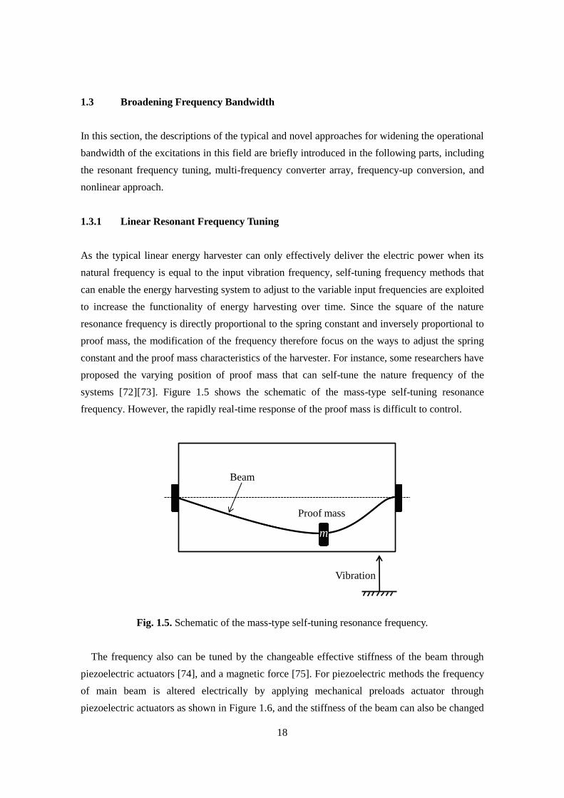
systems [72][73]. Figure 1.5 shows the schematic of the mass-type self-tuning resonance
frequency. However, the rapidly real-time response of the proof mass is difficult to control.
Fig. 1.5. Schematic of the mass-type self-tuning resonance frequency.
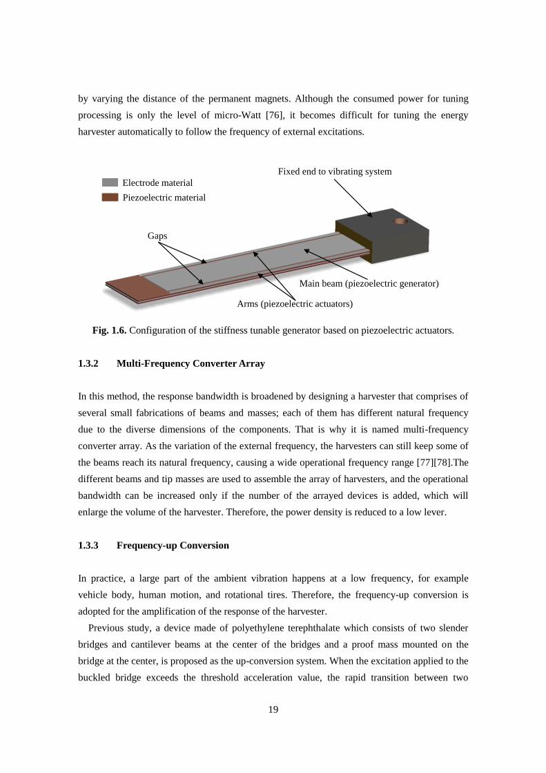
The frequency also can be tuned by the changeable effective stiffness of the beam through
piezoelectric actuators [74], and a magnetic force [75]. For piezoelectric methods the frequency
of main beam is altered electrically by applying mechanical preloads actuator through
piezoelectric actuators as shown in Figure 1.6, and the stiffness of the beam can also be changed
m
Beam
Proof mass
Vibration
19
by varying the distance of the permanent magnets. Although the consumed power for tuning
processing is only the level of micro-Watt [76], it becomes difficult for tuning the energy
harvester automatically to follow the frequency of external excitations.
Fig. 1.6. Configuration of the stiffness tunable generator based on piezoelectric actuators.
1.3.2 Multi-Frequency Converter Array
In this method, the response bandwidth is broadened by designing a harvester that comprises of
several small fabrications of beams and masses; each of them has different natural frequency
due to the diverse dimensions of the components. That is why it is named multi-frequency
converter array. As the variation of the external frequency, the harvesters can still keep some of
the beams reach its natural frequency, causing a wide operational frequency range [77][78].The
different beams and tip masses are used to assemble the array of harvesters, and the operational
bandwidth can be increased only if the number of the arrayed devices is added, which will
enlarge the volume of the harvester. Therefore, the power density is reduced to a low lever.
1.3.3 Frequency-up Conversion
In practice, a large part of the ambient vibration happens at a low frequency, for example
vehicle body, human motion, and rotational tires. Therefore, the frequency-up conversion is
adopted for the amplification of the response of the harvester.
Previous study, a device made of polyethylene terephthalate which consists of two slender
bridges and cantilever beams at the center of the bridges and a proof mass mounted on the
bridge at the center, is proposed as the up-conversion system. When the excitation applied to the
buckled bridge exceeds the threshold acceleration value, the rapid transition between two
Fixed end to vibrating system
Piezoelectric material
Electrode material
Gaps
Arms (piezoelectric actuators)
Main beam (piezoelectric generator)
20
equilibrium states generates a highly accelerated excitation of the buckled bridge, thereby
causing the attached beams to vibration freely at the natural resonance frequency independent of
the input frequency[79]. However, in the most cases, the vibrational amplitude of the ambient
excitation cannot always appear adequately large over wide range of frequency, which leads to
the excitation source that is too weak to stimulate the bridge for transiting between equilibrium
states going on all the time. Other related researches was presented in the literatures [80], a
two-stage cantilever beam and a mass-spring system with mechanical energy transfer teeth as
the fabricated parts of the energy harvester that can intermittently transfer its primary vibrating
energy to one or more secondary vibrating beams. However, in this case, the problem is that the
more vibrating energy will dissipate because of the impact between transfer teeth and beams.
1.3.4 Nonlinear Approach
Many researchers have recently exploited the nonlinearity systems as a means to extend the
coupling between the excitation and a harmonic oscillator to a wider broadband of the frequency
for enhancing the transduction of vibrating energy harvesters. The most common approaches to
the design of such systems introduce a nonlinear restoring force based on the using of the
magnetic or mechanical forces [81][82][83]. According to the type of nonlinearity, the nonlinear
energy harvesters can be generally classified into monostable, bistable cases and more than two
stable states named multi-stable in this dissertation. In the condition of certain harmonic
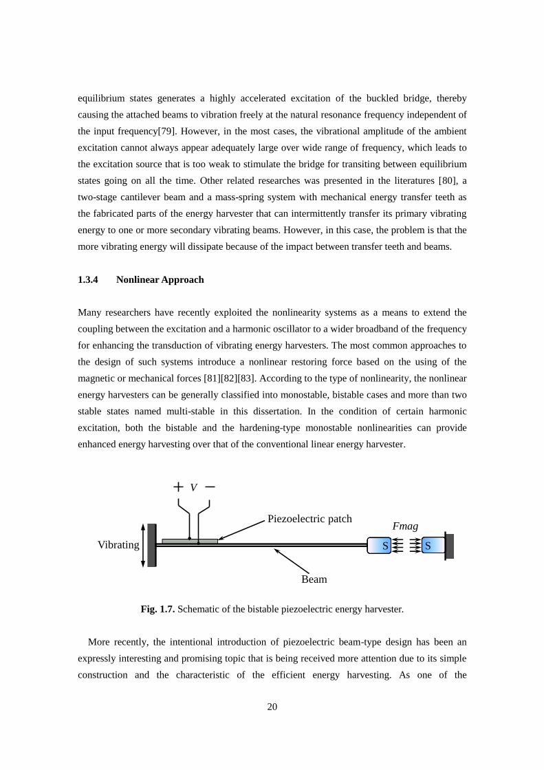
excitation, both the bistable and the hardening-type monostable nonlinearities can provide
enhanced energy harvesting over that of the conventional linear energy harvester.
Fig. 1.7. Schematic of the bistable piezoelectric energy harvester.
More recently, the intentional introduction of piezoelectric beam-type design has been an
expressly interesting and promising topic that is being received more attention due to its simple
construction and the characteristic of the efficient energy harvesting. As one of the
Fmag
Beam
Vibrating
Piezoelectric patch
V
S S
21
representative configuration shown in Figure 1.7, a magnet is attached to the end of the beam
while another one is fixed in the reference frame. The restoring force can be adjusted by altering
the distance between two magnets, when the distance is kept on the certain value, the beam can
show the behavior of the nonlinearity meanwhile have two stable states. By the parameter
design, the response of the beam can be induced a jump-up action owing to the effect of the
high orbit of the bistable system [41].
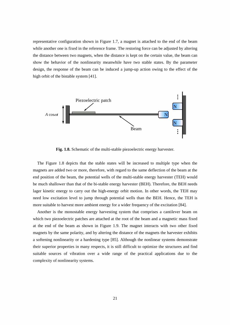
Fig. 1.8. Schematic of the multi-stable piezoelectric energy harvester.
The Figure 1.8 depicts that the stable states will be increased to multiple type when the
magnets are added two or more, therefore, with regard to the same deflection of the beam at the
end position of the beam, the potential wells of the multi-stable energy harvester (TEH) would
be much shallower than that of the bi-stable energy harvester (BEH). Therefore, the BEH needs
lager kinetic energy to carry out the high-energy orbit motion. In other words, the TEH may
need low excitation level to jump through potential wells than the BEH. Hence, the TEH is
more suitable to harvest more ambient energy for a wider frequency of the excitation [84].
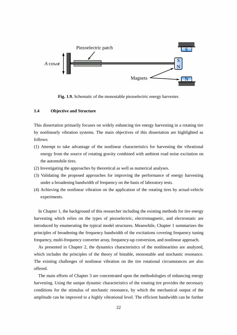
Another is the monostable energy harvesting system that comprises a cantilever beam on
which two piezoelectric patches are attached at the root of the beam and a magnetic mass fixed
at the end of the beam as shown in Figure 1.9. The magnet interacts with two other fixed
magnets by the same polarity, and by altering the distance of the magnets the harvester exhibits
a softening nonlinearity or a hardening type [85]. Although the nonlinear systems demonstrate
their superior properties in many respects, it is still difficult to optimize the structures and find
suitable sources of vibration over a wide range of the practical applications due to the
complexity of nonlinearity systems.
Beam
Piezoelectric patch
……
A cost N
N
N
22
Fig. 1.9. Schematic of the monostable piezoelectric energy harvester.
1.4 Objective and Structure
This dissertation primarily focuses on widely enhancing tire energy harvesting in a rotating tire
by nonlinearly vibration systems. The main objectives of this dissertation are highlighted as
follows:
(1) Attempt to take advantage of the nonlinear characteristics for harvesting the vibrational
energy from the source of rotating gravity combined with ambient road noise excitation on
the automobile tires.
(2) Investigating the approaches by theoretical as well as numerical analyses.
(3) Validating the proposed approaches for improving the performance of energy harvesting
under a broadening bandwidth of frequency on the basis of laboratory tests.
(4) Achieving the nonlinear vibration on the application of the rotating tires by actual-vehicle
experiments.
In Chapter 1, the background of this researcher including the existing methods for tire energy
harvesting which relies on the types of piezoelectric, electromagnetic, and electrostatic are
introduced by enumerating the typical model structures. Meanwhile, Chapter 1 summarizes the
principles of broadening the frequency bandwidth of the excitations covering frequency tuning
frequency, multi-frequency converter array, frequency-up conversion, and nonlinear approach.
As presented in Chapter 2, the dynamics characteristics of the nonlinearities are analyzed,
which includes the principles of the theory of bistable, monostable and stochastic resonance.
The existing challenges of nonlinear vibration on the tire rotational circumstances are also
offered.
The main efforts of Chapter 3 are concentrated upon the methodologies of enhancing energy
harvesting. Using the unique dynamic characteristics of the rotating tire provides the necessary
conditions for the stimulus of stochastic resonance, by which the mechanical output of the
amplitude can be improved to a highly vibrational level. The efficient bandwidth can be further
Piezoelectric patch
A cost
Magnets
S
N
S
N

23
broadened under considering the combination of stochastic resonance with the high energy orbit
oscillation. However, owing to the existence of the low energy orbit, how to maintain the
stability of the high energy orbit for a wide range of driving speeds becomes an important
challenge. Consequently, in Chapter 3, proposing an approach using centrifugal force of tire
rotating for tuning the stiffness of the cantilever ensures that the high energy orbit oscillation
can be stabilized for a wider bandwidth rather than jumping down the low energy orbit.
In Chapter 4, by the numerical analyses and simulation investigations, the occurrence of
stochastic resonance is feasible under both simulating condition and measured on-road noise
excitation. And the valid bandwidth is possible to be enlarged to a wider range by combining
stochastic resonance with high energy orbit motion, and stabilizing the high energy orbit motion
by transferring the initial system from the behavior of bistable to monostable.
In Chapter 5, the experiment study including the laboratory as well the actual-vehicle
experiments, are carried out for the validation of the effectiveness of the proposed nonlinear
systems that the power harvested is enhanced by a mW level from a rotating tire by the
particular nonlinear vibration or the mixture of different types of nonlinear characteristics.
In Chapter 6, the discussions regarding the coexistence of three different nonlinear oscillating
phenomena of stochastic resonance, high energy orbit motions of bistable and monostable, are
furthered for confirmation of the combined nonlinear vibrations. After that, the design of the
rectifier circuit and the comparison with other energy harvesting strategies are discussed in the
end.
In Chapter 7, it concludes the details and significances of this research.
24
Chapter 2
Energy Harvesting from Nonlinear Vibration
25
2. Energy Harvesting from Nonlinear Vibration
2.1 Nonlinear Systems
In this chapter, the basic dynamics and its characteristics are introduced for the monostable and
bistable Duffing oscillators under harmonic excitations, which will be used for the theoretical
derivation in the following chapters.
2.1.1 Monostable Energy Harvester
The motion Equation of a monostable piezoelectric beam-based harvester under a harmonic
excitation can be obtained as
3
0sinT T T Tmx cx ax bx F t , (2.1)
0, 0 0,a b or b
where xT is the relative displacement, and m is the seismic mass which is coupled with a
restoring force with cubic nonlinearity and an energy transducer with damping coefficient c,
excited by a harmonic force 0cosF t , t is the real time, F is the amplitude of harmonic
force, is the angular velocity of harmonic force, and 0 is the initial phase angle between the
excitation and the response. The symbol of a is the linear coefficient term of the nonlinear
system, the negative value represent the bistable type, or else the system reflects the monostable
behavior. The symbol of b is the nonlinear coefficient term of the nonlinear system. The
positive and negative nonlinearity of b indicate a hardening and softening characteristics,
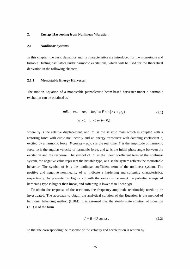
respectively. As presented in Figure 2.1 with the same displacement the potential energy of
hardening type is higher than linear, and softening is lower than linear type.
To obtain the response of the oscillator, the frequency-amplitude relationship needs to be
investigated. The approach to obtain the analytical solution of the Equation is the method of
harmonic balancing method (HBM). It is assumed that the steady state solution of Equation
(2.1) is of the form
cosu B U t , (2.2)
so that the corresponding the response of the velocity and acceleration is written by
26
sinu U t , (2.3)
then
2 cosu U t . (2.4)
Fig. 2.1. Potential energy diagrams for the three cases: hardening, softening, and linear types.
Submitting the Equations (2.2), (2.3) and (2.4) into the Equation (2.1), it is arranged to
2 3 3
0cos sin cos (cos t) sinm U t c U t aU t bU F t . (2.5)
The term of b is equally transformed using elementary trigonometric relations. By ignoring the
super harmonics, it gives as
3 3 3 33 1(cos t) cos cos(3 )
4 4bU bU t bU t . (2.6)
Substituting the Equation (2.6) into Equation (2.5), the re-arranged frequency-amplitude
Equation is shown as
-0.05 0 0.050
0.02
0.04
0.06
0.08
0.1
0.12
0.14
Displacement (m)
Po
ten
tial
en
erg
y (
J)
Hardening
Softening
Linear
27
2 3
0 0
3cos sin sin cos cos sin
4m U aU bU t c U t F t F t
, (2.7)
by equating the coefficient terms of the cos t and sin t , the following relationships are
given
2 3
0
3sin
4m U aU bU F , (2.8a)
0cosc U F . (2.8b)
Squaring the Equations (2.8a) and (2.8b) respectively, and summarizing them to obtain
2
2 6 2 4 2 2 2 2 29 30
16 2b U b m a U m a c U F
. (2.9)
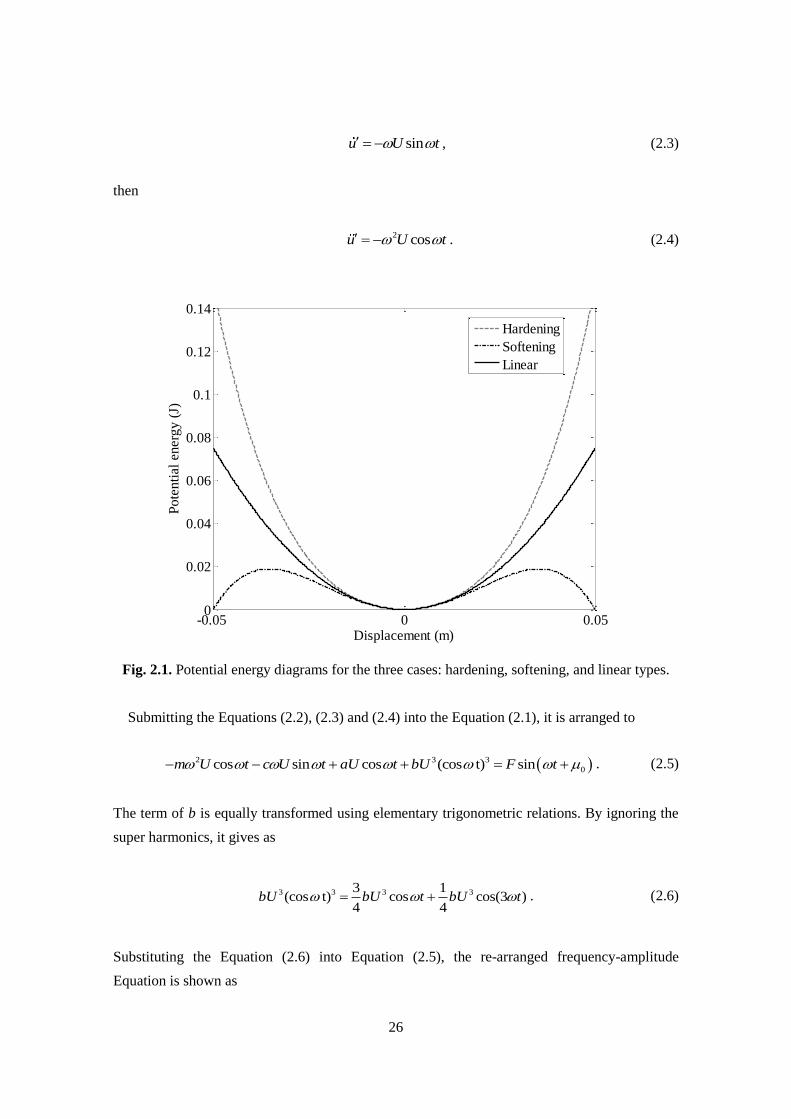
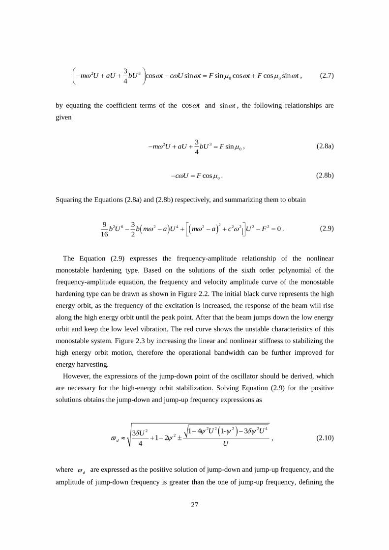
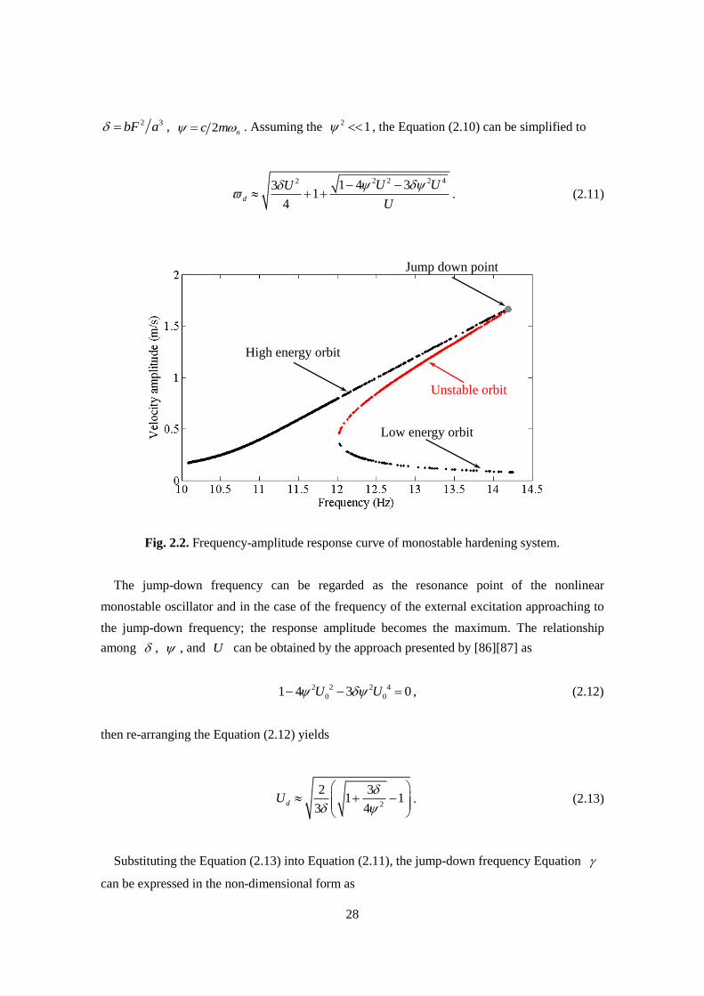
The Equation (2.9) expresses the frequency-amplitude relationship of the nonlinear
monostable hardening type. Based on the solutions of the sixth order polynomial of the
frequency-amplitude equation, the frequency and velocity amplitude curve of the monostable
hardening type can be drawn as shown in Figure 2.2. The initial black curve represents the high
energy orbit, as the frequency of the excitation is increased, the response of the beam will rise
along the high energy orbit until the peak point. After that the beam jumps down the low energy
orbit and keep the low level vibration. The red curve shows the unstable characteristics of this
monostable system. Figure 2.3 by increasing the linear and nonlinear stiffness to stabilizing the
high energy orbit motion, therefore the operational bandwidth can be further improved for
energy harvesting.
However, the expressions of the jump-down point of the oscillator should be derived, which
are necessary for the high-energy orbit stabilization. Solving Equation (2.9) for the positive
solutions obtains the jump-down and jump-up frequency expressions as
2 2 2 2 42
21 4 1- 33
1 24
d
U UU
U
, (2.10)
where d are expressed as the positive solution of jump-down and jump-up frequency, and the
amplitude of jump-down frequency is greater than the one of jump-up frequency, defining the
28
2 3bF a , 2 nc m . Assuming the 2 1 , the Equation (2.10) can be simplified to
2 2 2 42 1 4 331
4d
U UU
U
. (2.11)
Fig. 2.2. Frequency-amplitude response curve of monostable hardening system.
The jump-down frequency can be regarded as the resonance point of the nonlinear
monostable oscillator and in the case of the frequency of the external excitation approaching to
the jump-down frequency; the response amplitude becomes the maximum. The relationship
among , , and U can be obtained by the approach presented by [86][87] as
2 2 2 4
0 01 4 3 0U U , (2.12)
then re-arranging the Equation (2.12) yields
2
2 31 1
3 4dU
. (2.13)
Substituting the Equation (2.13) into Equation (2.11), the jump-down frequency Equation
can be expressed in the non-dimensional form as
High energy orbit
Low energy orbit
Unstable orbit
Jump down point
29
2
1 31 1
2 4d
. (2.14)
The dimensional expression of jump-down frequency is yielded by substituting the equation of
its natural frequency of nonlinear system n a m into Equation (2.15) as
n d , (2.15)
Substituting Equation (2.14) into Equation (2.15) and considering the relationships of
2 3bF a , 2 nc m obtain the specific dimensional expression of jump-down
frequency as
22
2
1 3
2 2
mbF aa
m c m
. (2.16)
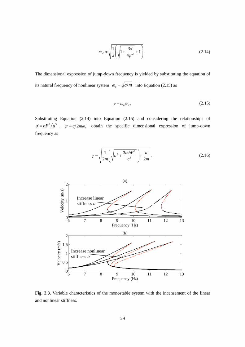
Fig. 2.3. Variable characteristics of the monostable system with the incensement of the linear
and nonlinear stiffness.
6 7 8 9 10 11 12 130
1
2(a)
Frequency (Hz)
Vel
oci
ty (
m/s
)
6 7 8 9 10 11 12 130
0.5
1
1.5
2(b)
Frequency (Hz)
Vel
oci
ty (
m/s
)
Increase linear
stiffness a
Increase nonlinear
stiffness b
30
2.1.2 Bistable Energy Harvester
The motion Equation of bistable oscillator can be expressed in dimensional form as
3
0sinT T T Tmx cx ax bx F t , (2.17)
0, 0a b ,
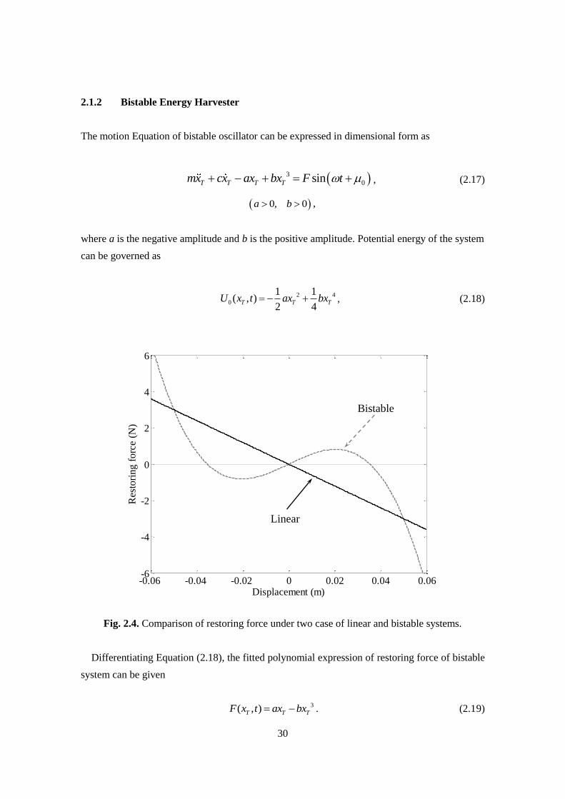
where a is the negative amplitude and b is the positive amplitude. Potential energy of the system
can be governed as
2 4
0
1 1( , )
2 4T T TU x t ax bx , (2.18)
Fig. 2.4. Comparison of restoring force under two case of linear and bistable systems.
Differentiating Equation (2.18), the fitted polynomial expression of restoring force of bistable
system can be given
3( , )T T TF x t ax bx . (2.19)
-0.06 -0.04 -0.02 0 0.02 0.04 0.06-6
-4
-2
0
2
4
6
Displacement (m)
Res
tori
ng
fo
rce
(N)
Bistable
Linear
31
As shown in Figure 2.4, in the case of the typical linear system, it has only one stable point
around the equilibrium position. Otherwise, in the case of the bistable system, there are two
stable states also the restoring force decreasing linearly.
Using the HBM the same with the monostable case, the frequency-amplitude response
equation of bistable can also be obtained, which can be expressed as
2
2 6 2 4 2 2 2 2 29 30
16 2b U b m a U m a c U F
. (2.20)
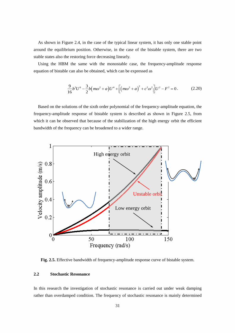
Based on the solutions of the sixth order polynomial of the frequency-amplitude equation, the
frequency-amplitude response of bistable system is described as shown in Figure 2.5, from
which it can be observed that because of the stabilization of the high energy orbit the efficient
bandwidth of the frequency can be broadened to a wider range.
Fig. 2.5. Effective bandwidth of frequency-amplitude response curve of bistable system.
2.2 Stochastic Resonance
In this research the investigation of stochastic resonance is carried out under weak damping
rather than overdamped condition. The frequency of stochastic resonance is mainly determined
High energy orbit
Low energy orbit
Unstable orbit
32
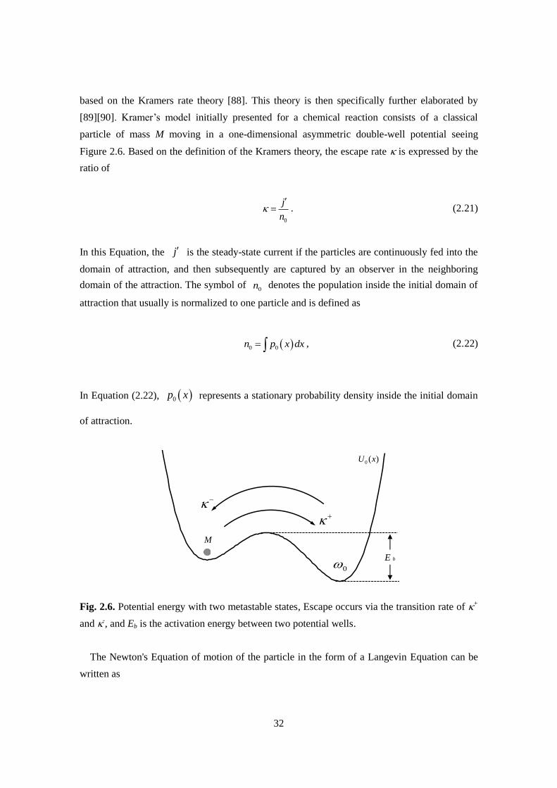
based on the Kramers rate theory [88]. This theory is then specifically further elaborated by
[89][90]. Kramer’s model initially presented for a chemical reaction consists of a classical
particle of mass M moving in a one-dimensional asymmetric double-well potential seeing
Figure 2.6. Based on the definition of the Kramers theory, the escape rate is expressed by the
ratio of
0
j
n
. (2.21)
In this Equation, the j is the steady-state current if the particles are continuously fed into the
domain of attraction, and then subsequently are captured by an observer in the neighboring
domain of the attraction. The symbol of 0n denotes the population inside the initial domain of
attraction that usually is normalized to one particle and is defined as
0 0n p x dx , (2.22)
In Equation (2.22), 0p x represents a stationary probability density inside the initial domain
of attraction.
Fig. 2.6. Potential energy with two metastable states, Escape occurs via the transition rate of +
and -, and Eb is the activation energy between two potential wells.
The Newton's Equation of motion of the particle in the form of a Langevin Equation can be
written as
0
E b
M
0 ( )U x

33
0Mx U x Mx t , (2.23)
where the x is the displacement from the equilibrium position, is a constant damping
coefficient, and t denotes ambient noise. The time evolution of the probability density
, ,p x x t of the particle transition to the energy barrier is governed by the Klein-Kramers
Equation [88][91] as
2
2
, ,, ,B
p x t U x M k Tp x t
t x M M
, (2.24)
The symbols of Bk T here is regarded as the power intensity of the ambient vibration. In the
case of weak friction, the energy, or equivalently action is almost constant and is given as
I E p dq . (2.25)
Then, yields a diffusion Equation for the probability density of the action [92] as
, 21 ,B
p I t k TI p I t
t I I I
, (2.26)
where I is the angular frequency at the action I,
2
IE
I
. (2.27)
Then the diffusion of the action given in Equation (2.26) can be immediately transformed into a
diffusion equation with respect to energy E ,
34
,1 ,
2B
p E t EI E k T p E t
t E E
. (2.28)
As soon as the particle has acquired an energy which is larger than the barrier height of bE , the
particle can escape from the well. The energy that is captured by the particle is defined as the
( )b bI I E . In this case the steady-state current is obtained by the stationary probability density,
21 , 0B
b
k Tj I p I I I
I I
. (2.29)
Imposing an immediate absorption at bI I , that is 0bp I I , one finds with
1
Bk T
from Equation (2.29).
1exp
exp2
bI
I
E Ip I j E I I dI
I
. (2.30)
Substituting Equation (2.30) into Equation (2.22), integrating it with respect to I , yields
1
0
expexp
2
b bI I
I I
E In j E I I dI dI
I
. (2.31)
Substituting Equation (2.31) into Equation (2.21) the rate is given as
1 1
0
expexp
2
b bI I
I I
E In j E I I dI dI
I
. (2.32)
In generally, the ambient vibration is too weak to excite the particle to transit from the potential
well, because the ambient vibration energy is smaller than the potential energy of the wells.
Hence, it can be defined that 1
B bk T D E , owing to the relationship as presented in
Equation (2.27), the rate is reduced to
1
0
2exp b
b
EI E
. (2.33)

35
Hence, for the weak damping, the Kramers rate is obtained as
0 exp2
b bI E E
, (2.34)
which is valid expression for the transmitting rate if the intensity of the noise satisfies the
following conditions:
1,B
b
k T
E and b BI E k T . (2.35)
Then the expression of the Equation (2.34) can be re-considered as
0 exp2
bE
. (Hz) (2.36)
Due to existence of the double potential wells, the frequency of stochastic resonance can be
expressed by
0 exp2
bSR
E
D
. (rad/s) (2.37)
2.3 Challenges on Rotational Energy Harvester
Through the above analysis of the nonlinear system, it can be clearly found that it has several
advantages to improve the energy recovery. First of all, one of the main reasons is that it can
achieve a broadband energy harvesting through a relative simple structure. Then, because there
has no restriction of the stroke of the nonlinear energy harvesters compared many linear systems
that results in the dynamic responses of the vibrating body can be maintained at a high level.
Finally, the enhanced responses improve the performance of energy harvesting for widely
applications.
However, due to the complexity of the dynamic characteristics of nonlinear systems, although
it has been discussed by many researchers in theoretical investigations and laboratory
experiments, it is still difficult to realize the application of the advantages of the nonlinear
system to the actual environments, especially in the energy harvesting field. As the first
challenges of this study is how to exploit nonlinear systems to the actual vehicle tires, and can

36
fully demonstrate their characteristics.
In addition, by using the currently available tire vibration power generation technologies,
only a few micro-Watts of harvested power can be provided to power just one or two sensors,
e.g. MEMS devices with a relatively high power density. With the increasing requirements of
advanced driving assistance systems, a tire-pressure monitoring system that can provide the
driver with the tire condition via wireless transmission is integrated with a growing number of
sensors. Consequently, another challenge of this study is to improve the current stage of power
generation for self-sufficient power so that it can guarantee more and more sensors working.
37
Chapter 3
Methodology for Rotation-Induced Energy
Harvesting
38
3. Methodology for Rotation-Induced Energy Harvesting
3.1 Bistable System under Rotating Circumstances
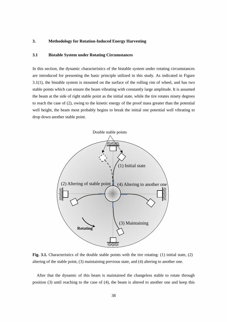
In this section, the dynamic characteristics of the bistable system under rotating circumstances
are introduced for presenting the basic principle utilized in this study. As indicated in Figure
3.1(1), the bistable system is mounted on the surface of the rolling rim of wheel, and has two
stable points which can ensure the beam vibrating with constantly large amplitude. It is assumed
the beam at the side of right stable point as the initial state, while the tire rotates ninety degrees
to reach the case of (2), owing to the kinetic energy of the proof mass greater than the potential
well height, the beam most probably begins to break the initial one potential well vibrating to
drop down another stable point.
Fig. 3.1. Characteristics of the double stable points with the tire rotating: (1) initial state, (2)
altering of the stable point, (3) maintaining previous state, and (4) altering to another one.
After that the dynamic of this beam is maintained the changeless stable to rotate through
position (3) until reaching to the case of (4), the beam is altered to another one and keep this
Double stable points
Rotating
(1) Initial state
(2) Altering of stable point
(3) Maintaining
(4) Altering to another one
39
kind vibrating to return the initial state. Therefore, per one cycle of rotation the beam can be
realized to vibrate through potential wells for two times with amplified amplitude, which is
hence considered to be an effective structure to enhance tire rotation-induced energy harvesting.
3.2 Modelling for Simulated Tire Rotation
3.2.1 Mathematical Analysis
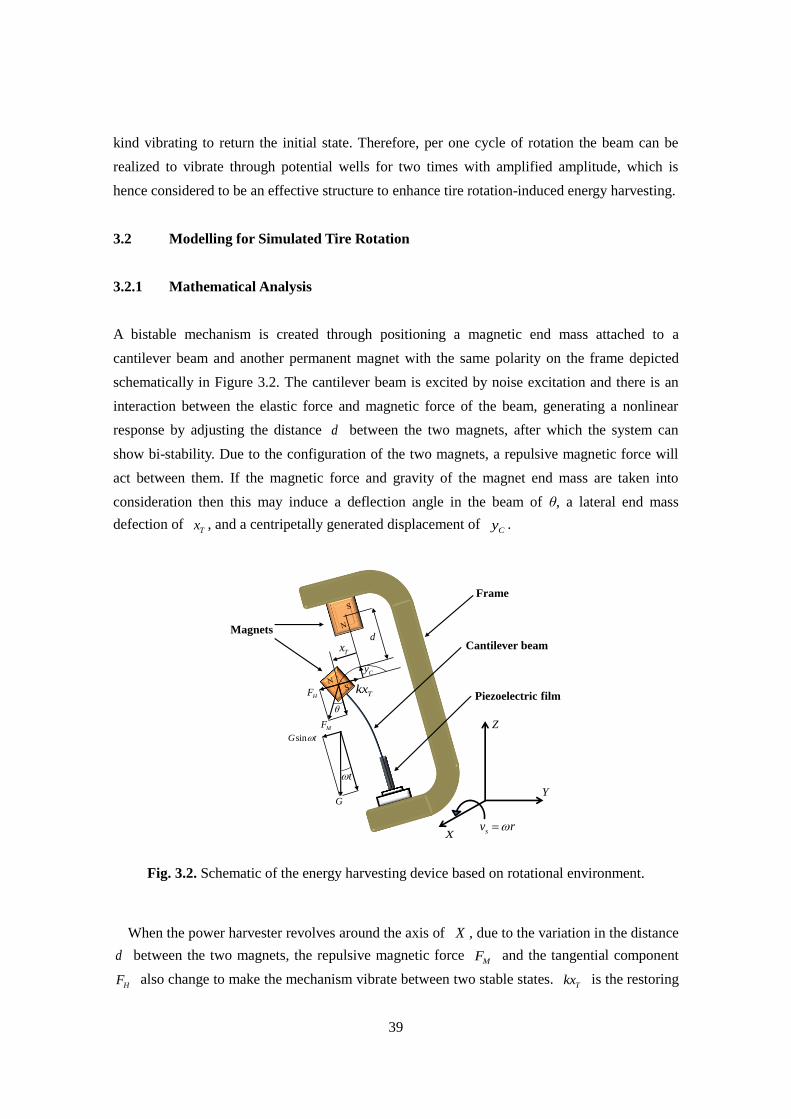
A bistable mechanism is created through positioning a magnetic end mass attached to a
cantilever beam and another permanent magnet with the same polarity on the frame depicted
schematically in Figure 3.2. The cantilever beam is excited by noise excitation and there is an
interaction between the elastic force and magnetic force of the beam, generating a nonlinear
response by adjusting the distance d between the two magnets, after which the system can
show bi-stability. Due to the configuration of the two magnets, a repulsive magnetic force will
act between them. If the magnetic force and gravity of the magnet end mass are taken into
consideration then this may induce a deflection angle in the beam of θ, a lateral end mass
defection of Tx , and a centripetally generated displacement of
Cy .
Fig. 3.2. Schematic of the energy harvesting device based on rotational environment.
When the power harvester revolves around the axis of X , due to the variation in the distance
d between the two magnets, the repulsive magnetic force MF and the tangential component
HF also change to make the mechanism vibrate between two stable states. Tkx is the restoring
sinG t
Y
X sv r
t
MF
HF
d
Tx
G
Z
Magnets
Cantilever beam
Frame
Piezoelectric filmTkx
Cy
40
force of the cantilever beam. HF can be derived from Equation (3.2) using a dipole model
[93][94] and expanded into a Taylor series, which the details can be found at the next section,
calculated around 0My and truncated to Equation (3.3) as
sinH MF F , (3.1)
2
5/22 2
2
7/22 2
3 3
4
15
4
cy fx T fy cx fy T fx
H
T
T T fx fy T cx cy
T
M dM x M M dM x MvF
d x
x x M dM x M dMv
d x
, (3.2)
2
5
2 3
7
9 12
4
75 90
8
cx fx cy fy
H T
cx fx cy fy
T
M M M MF v x
d
M M M Mv x
d
, (3.3)
where v and are the volume of the magnets and the permeability of free space. Mf = (Mfx,
Mfy), Mc = (Mcx, Mcy) are the magnetization strength amplitudes of permanent magnet attached
on the frame and the magnetic end mass, respectively. When considering the centripetal force
resulting from revolution of the frame, it becomes necessary to take into account the effect of
gravity G of magnetic end mass. Therefore, the resultant force of the tangential direction Hf
can be expressed as
0sinH H Tf F kx G t . (3.4)
When the frame with a radius of r revolves at the angular velocity of with the speed of
Sv , the total kinetic energy of the end mass will be defined by KE as
2 21
2K T S CE m x v y
. (3.5)

41
Thereby, according to the thin beam theory, the restoring coefficient of the beam, with the
Young’s modulus and the moment of inertia of E and I , is given as
2
0
l
k E I dx , (3.6)
where ( )x is a static linear shape function of the cantilever beam. Assuming ( ) ( , )Tx t w L t ,
where L is the length of the beam, the following equation can be derived as
2 3
2 3
3( , ) ( ) ( , ) ( )
2 2T
x xw x t x w L t x t
L L
, (3.7)
where w is the transverse displacement of the beam and 2 2w d w dx . Assuming the
transverse deflection is insignificant, Cy is given by
2 2
2 2
0 0 0
1 11 1
2 2
L L L
C T
dw dwy dx dx x
dx dx
. (3.8)
According to Equations (3.4), (3.5) and (3.8), Lagrange’s Equation can be given by
0sinK KH T
T T
E EdF kx G t
dt x x
. (3.9)
The Equation of motion of the system is derived as
2
5
2
3
07
9 12
4
75 90( ) sin
8
cx fx cy fy
T T T
cx fx cy fy
T
M M M Mmx cx k v x
d
v M M M Mx N t G t
d
, (3.10)
42
where c is the viscous damping coefficient, the term of 2 59 12 4cx fx cy fyv M M M M d is the
linear coefficient of the two magnets, and 2 775 90 8cx fx cy fyv M M M M d is the nonlinear
coefficient of the two magnets. When 2 59 12 4cx fx cy fyk v M M M M d a and
2 775 90 8cx fx cy fyv M M M M d b ( 0,a 0)b , the Equation (3.10) can be transformed
into
3
0( ) sinT T T Tmx cx ax bx N t G t . (3.11)
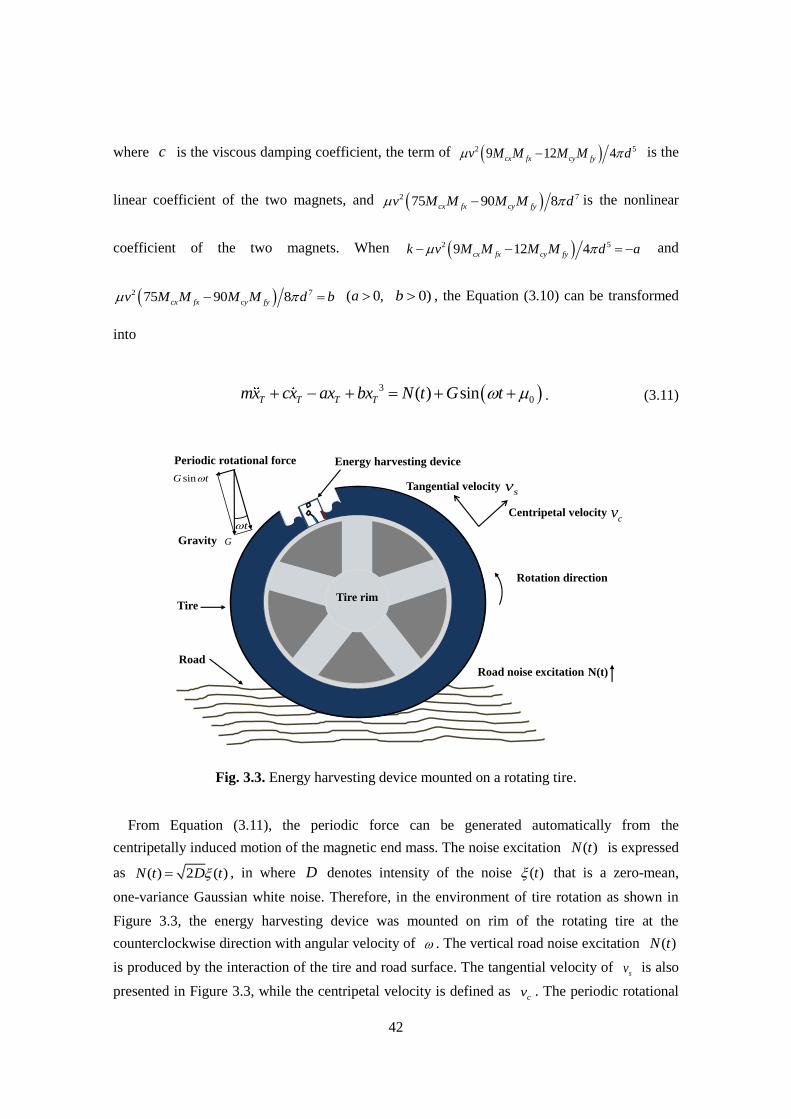
Fig. 3.3. Energy harvesting device mounted on a rotating tire.
From Equation (3.11), the periodic force can be generated automatically from the
centripetally induced motion of the magnetic end mass. The noise excitation ( )N t is expressed
as ( ) 2 ( )N t D t , in where D denotes intensity of the noise ( )t that is a zero-mean,
one-variance Gaussian white noise. Therefore, in the environment of tire rotation as shown in
Figure 3.3, the energy harvesting device was mounted on rim of the rotating tire at the
counterclockwise direction with angular velocity of . The vertical road noise excitation ( )N t
is produced by the interaction of the tire and road surface. The tangential velocity of sv is also
presented in Figure 3.3, while the centripetal velocity is defined as cv . The periodic rotational
sv
cv
Road
Rotation direction
Energy harvesting device
Tire
Road noise excitation
Periodic rotational force
Tyre rim
sinG t
t
G
N(t)
Tangential velocity
Centripetal velocity
Gravity
Tire rim

43
force sinG t is autonomously offered from the gravitational effect of the magnetic end mass
and the rotation of the tire, where G is the gravity of the magnetic end mass. Hence, the
proposed energy harvester model is capable of being utilized under the vehicle tire rotation
environments.
3.2.2 Stochastic Resonance Frequency
In the presence of tire rotation, the standard potential energy Equation can be transformed from
Equation (3.12) into Equation (3.13) as
2 41 1( , )
2 4T T TU x t ax bx , (3.12)
2 4
0
1 1( , ) sin
2 4T T T TU x t ax bx G t x . (3.13)
As shown in Figure 3.4, in the absence of tire rotation, the double potential wells remain
symmetric. The minima are located at 0x . These are separated by double potential barriers
with the heights given by U . The detailed expression is calculated as
1 2
0 ( )x a b , 2 (4 )U a b . (3.14)
Hence, in the case of tire rotation, the double potential wells are asymmetrically tilted up and
down, periodically raising and lowering the potential wells [89]. The height of the potential
well becomes
2
0 0(4 ) sinU a b G a b t , (3.15)
Differentiating Equation (3.12) with respect to Tx leads to
3
M T TF ax bx , (3.16)
where MF is the nonlinear spring force. After differentiating MF the nonlinear spring
44
coefficient k can be given as follows
23 Tk a bx . (3.17)
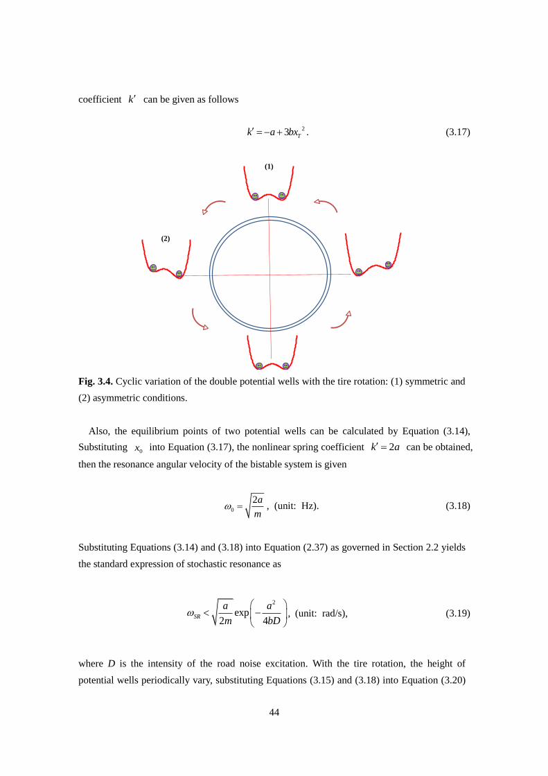
Fig. 3.4. Cyclic variation of the double potential wells with the tire rotation: (1) symmetric and
(2) asymmetric conditions.
Also, the equilibrium points of two potential wells can be calculated by Equation (3.14),
Substituting 0x into Equation (3.17), the nonlinear spring coefficient 2k a can be obtained,
then the resonance angular velocity of the bistable system is given
0
2a
m , (unit: Hz). (3.18)
Substituting Equations (3.14) and (3.18) into Equation (2.37) as governed in Section 2.2 yields
the standard expression of stochastic resonance as
2
exp2 4
SR
a a
m bD
, (unit: rad/s), (3.19)
where D is the intensity of the road noise excitation. With the tire rotation, the height of
potential wells periodically vary, substituting Equations (3.15) and (3.18) into Equation (3.20)
(1)
(2)
45
yields
2
0sin 4exp
2SR
G a b t a ba
m D
. (3.20)
Due to the influence of the term of sin t , it can result in that the frequency fluctuates up
and down around a certain value. It means that there is existence of a certain operating
frequency bandwidth corresponding to the calculated value, due to the effect of the periodic
modulation force.
According to the general model of a vibration energy harvester the damping coefficient c is
composed of the mechanical damping coefficient mc and the electrically induced damping
coefficient ec . Therefore, the motion Equation can be described by rearranging Equation (3.11)
as
2 3
0( ) ( ) (sin )T T e m T T T T T T Tmx x c c x ax x bx x N t x G t x . (3.21)
Then, Equation (3.21) can be transformed to
2 4 2 2
0
1 1 1( ) ( ) sin( )
2 4 2T T T e m T T T
dmx bx ax c c x N t x G t x
dt
. (3.22)
Equation (3.22) represents the fact that the instantaneous power into the system is equal to the
instantaneous power dissipated by damping plus the time rate of change of the sum of the
kinetic and potential energies. In the left side, the terms of 21 2 Tmx is the kinetic energy of the
system, and 4 21 4 1 2T Tbx ax presents the potential energy.
2( )e m Tc c x is the instantaneous
power absorbed by damping, 2
e Tc x is considered as the instantaneous power that can be
converted to electricity, and 2
m Tc x is the unavoidably lost power in mechanical damping. In
the right hand side terms, ( ) TN t x is the input power from the road ambient vibration, and
sin TG tx is power drawn due to the periodic force caused by the rotation of the tire and
gravity of the magnetic end mass. Therefore, the net instantaneous power that can be harvested
by this system can be given by
2
e TP c x . (3.23)
46
3.3 Modelling for Real-World Tire Rotation
3.3.1 Modified Stochastic Resonance Frequency
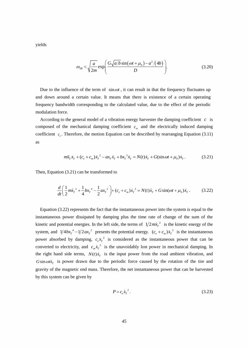
Figure 3.5 shows that a macro-scale energy harvester can be attached to a wheel rotating
counterclockwise with angular velocity ω. The vertical on-road noise N(t) is produced by the
interaction of the rotating tire and the road surface.
Fig. 3.5. Illustration of the energy harvester attached to the center of a wheel.
To eliminate the effect of the centrifugal forces, the center of the cantilever tip mass is located
at the rotational center of the wheel due to the sensitivity of cantilever beam stiffness to
centrifugal force, as shown in Figure 3.6.
To obtain the restoring force between the two magnets of the energy harvester, a
mathematical model is first derived for the interaction forces of the magnets. The dipole model
is used to represent the interaction forces, and the potential energy of the movable tip magnet can
be defined as
M cU = m B , (3.24)
where mc is the magnetic dipole moment vector of the fixed permanent magnet, defined by mc = Mc
v’. B is the magnetic flux density, Mc = (Mcx, Mcy) denotes the magnetization strength
amplitudes of the permanent magnet bonded to the frame in terms of its vertical and horizontal
components, and v is the volume of the magnets.
Tyre rim
Energy harvester
On-road noise N(t)
Tire wheel
ω
Road

47
Fig. 3.6. Diagram of the nonlinear tire-induced energy harvesting configuration.
Then, the potential energy of the magnetic end mass is expressed as
2
( )4
M
vU x
, (3.25)
where μ is the permeability of free space and x is the vibrational displacement of the end magnet.
The function Ф(x) is defined as
5/2 3/2
2 2 2 2
3( )
cy cx fy fx fy cy fx cxdM xM dM xM M M M M
xd x d x
, (3.26)
where d is the lateral separation of the two magnets. Note that Mf = (Mfx, Mfy) denotes the
magnetization strength of the magnetic tip mass in terms of its vertical and horizontal
components; the two magnets should have opposite polarity, indicating repulsion.
The restoring forces are obtained from the spatial derivative of the potential energy as
2
0( ) ( )4
M
vF x x
, (3.27)
where Θ(x) is expressed as
S NSN
Cantilever beam
Magnets
Frame
Piezoelectric film
d
x
Rotation direction
Center of tire rotation
48
5/2 7/2
2 2 2 2
3 3 15( )
cy fx fy cx fy fx fx fy cx cyM dM xM M dM xM x xM dM xM dM
xd x d x
. (3.28)
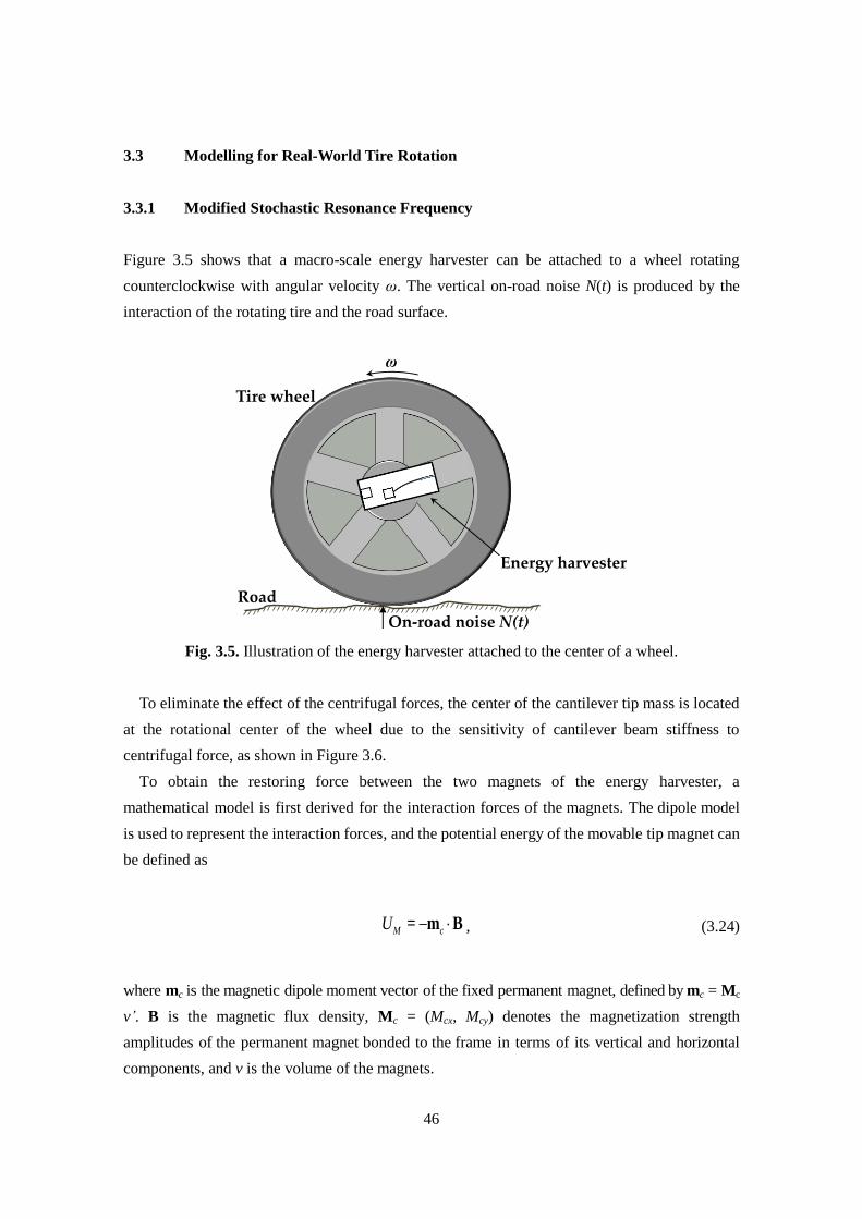
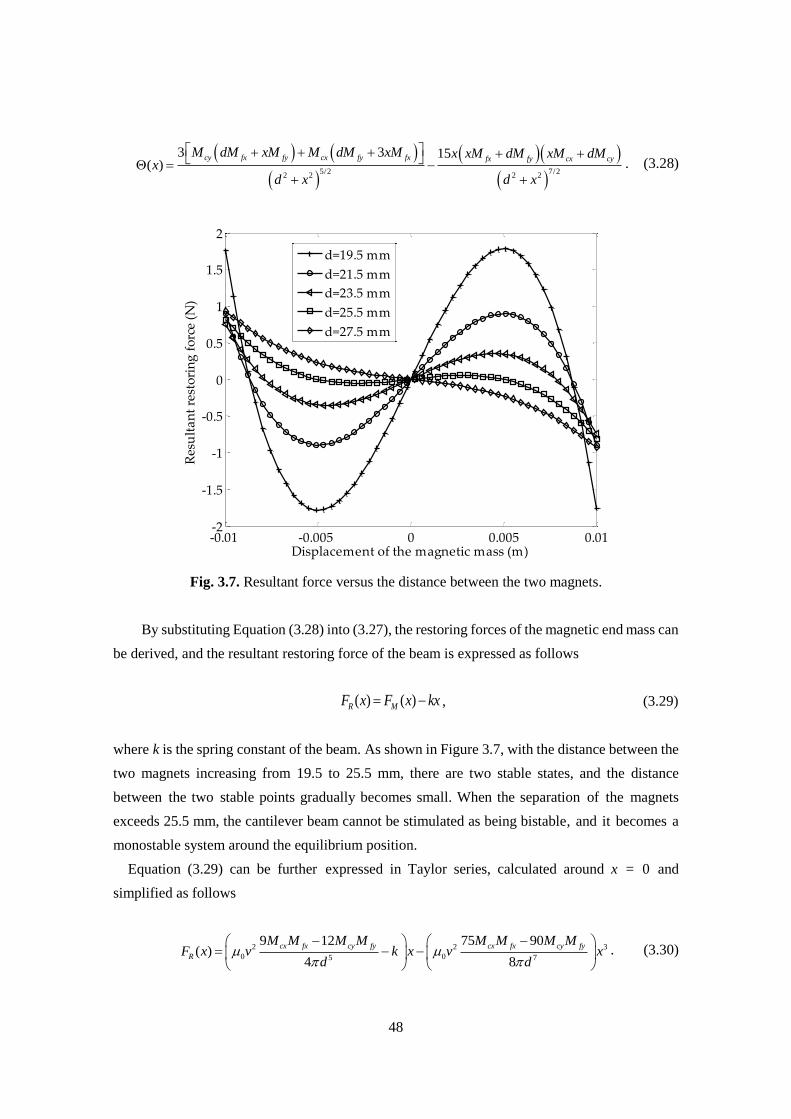
Fig. 3.7. Resultant force versus the distance between the two magnets.
By substituting Equation (3.28) into (3.27), the restoring forces of the magnetic end mass can
be derived, and the resultant restoring force of the beam is expressed as follows
( ) ( )R MF x F x kx , (3.29)
where k is the spring constant of the beam. As shown in Figure 3.7, with the distance between the
two magnets increasing from 19.5 to 25.5 mm, there are two stable states, and the distance
between the two stable points gradually becomes small. When the separation of the magnets
exceeds 25.5 mm, the cantilever beam cannot be stimulated as being bistable, and it becomes a
monostable system around the equilibrium position.
Equation (3.29) can be further expressed in Taylor series, calculated around x = 0 and
simplified as follows
2 2 3
0 05 7
9 12 75 90( )
4 8
cx fx cy fy cx fx cy fy
R
M M M M M M M MF x v k x v x
d d
. (3.30)
-0.01 -0.005 0 0.005 0.01-2
-1.5
-1
-0.5
0
0.5
1
1.5
2
Displacement of the magnetic mass (m)
Res
ult
an
t re
sto
rin
g f
orc
e (N
)
d=19.5 mm
d=21.5 mm
d=23.5 mm
d=25.5 mm
d=27.5 mm
49
Based on the Duffing dynamic expression of Equation (3.11), the resultant restoring force of
beam can be given as
3
MF ax bx . (3.31)
Due to the relation of FM’ = FR(x), Equations (3.32) and (3.33) are derived by employing the
corresponding constant terms of Equations (3.30) and (3.31), respectively.
2
0 5
9 12
4
cx fx cy fyM M M Ma v k
d
, (3.32)
2
0
7
75 90
8
cx fx cy fyv M M M Mb
d
. (3.33)
In the case of weak friction, the Kramers rate can be modified by substituting Equations (3.32)
and (3.33) into (3.19), the Kramers rate can be presented as a function of the distance between the
two magnets d.
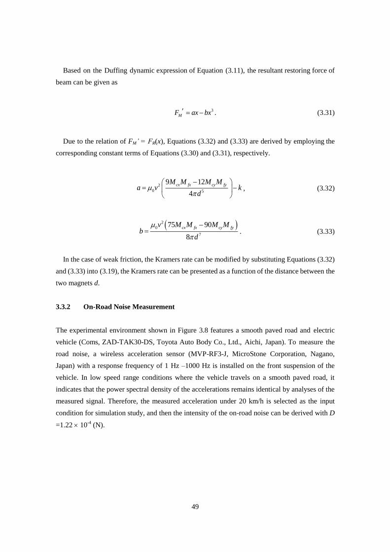
3.3.2 On-Road Noise Measurement
The experimental environment shown in Figure 3.8 features a smooth paved road and electric
vehicle (Coms, ZAD-TAK30-DS, Toyota Auto Body Co., Ltd., Aichi, Japan). To measure the
road noise, a wireless acceleration sensor (MVP-RF3-J, MicroStone Corporation, Nagano,
Japan) with a response frequency of 1 Hz –1000 Hz is installed on the front suspension of the
vehicle. In low speed range conditions where the vehicle travels on a smooth paved road, it
indicates that the power spectral density of the accelerations remains identical by analyses of the
measured signal. Therefore, the measured acceleration under 20 km/h is selected as the input
condition for simulation study, and then the intensity of the on-road noise can be derived with D
=1.22 10-4
(N).
50
Fig. 3.8. Paved road testing and on-road noise measurement on front-wheel suspension.
3.4 Combination of Stochastic Resonance and High Energy Orbit Oscillations
As described in Section 2.1.2, for harmonic excitation of the 0sinF t , the symbol of
F can be here considered as the gravity fore of G , due to only its gravitational acting,
especially at the lower frequency filed when one potential well motion of nonlinear bistable
system is dominant influence under periodical force excitation as shown in Figure 3.9. Before
the activation of two potential wells oscillating, the one potential well vibrating always exists
for reducing the effective bandwidth of the bistable system. By exploiting energy of the on-road
noise N(t), the low level motion of one potential well can be activated to the high level motion
of two potential wells owing to the stimulus of stochastic resonance. Thereby, this approach is
considered as a promising combination of two phenomena of stochastic resonance and high
energy orbit oscillation, by which the effective bandwidth can be broadened for further
improving the performances of bistable systems.
Accelerometer
Measurement location
Front suspension
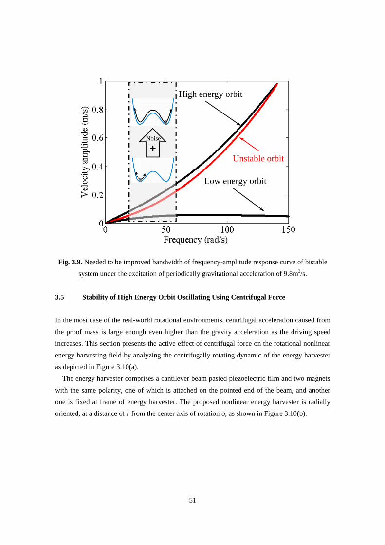
51
Fig. 3.9. Needed to be improved bandwidth of frequency-amplitude response curve of bistable
system under the excitation of periodically gravitational acceleration of 9.8m2/s.
3.5 Stability of High Energy Orbit Oscillating Using Centrifugal Force
In the most case of the real-world rotational environments, centrifugal acceleration caused from
the proof mass is large enough even higher than the gravity acceleration as the driving speed
increases. This section presents the active effect of centrifugal force on the rotational nonlinear
energy harvesting field by analyzing the centrifugally rotating dynamic of the energy harvester
as depicted in Figure 3.10(a).
The energy harvester comprises a cantilever beam pasted piezoelectric film and two magnets
with the same polarity, one of which is attached on the pointed end of the beam, and another
one is fixed at frame of energy harvester. The proposed nonlinear energy harvester is radially
oriented, at a distance of r from the center axis of rotation o, as shown in Figure 3.10(b).
High energy orbit
Low energy orbit
Unstable orbit
Noise
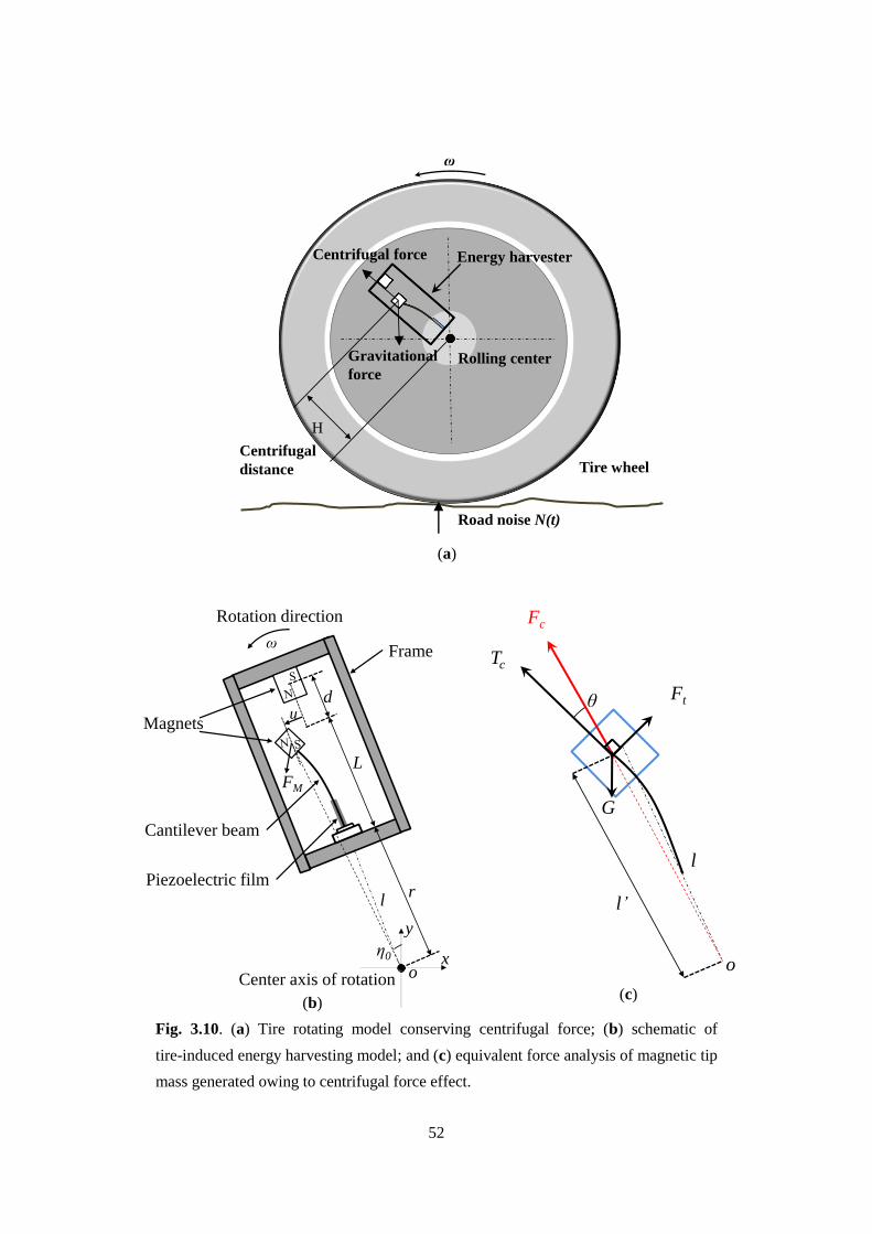
52
(a)
Fig. 3.10. (a) Tire rotating model conserving centrifugal force; (b) schematic of
tire-induced energy harvesting model; and (c) equivalent force analysis of magnetic tip
mass generated owing to centrifugal force effect.
Energy harvester
Tire wheel
ω
Gravitational
force
Centrifugal force
Road noise N(t)
Rolling center
H
Centrifugal
distance
FM
d
L
r
u
ωFrame
Magnets
Piezoelectric film
Cantilever beam
Rotation direction
Center axis of rotation
l
ox
y
η0
(b)
(c)
θ
Fc
Ft
Tc
l
l’
o
G

53
While the device model rotates on the anticlockwise direction with the angular frequency of ω,
as analyzed in Figure 3.10(c) the tensile stress generated from the centrifugal force of the tip
mass is yielded as
2 ( ) cF t m l t , (3.34)
in which m is the tip mass, l’ is the distance from the center axis of rotation to center of gravity
of the tip mass, and the l’ can be expressed as
2 2( ) l t L r u t , (3.35)
where L is the length of the beam, r is the distance from the root of the beam to the center axis
of rotation, and u is the vibrational amplitude of the cantilever beam at the tip position, by
rearranging the Equation (3.35), the approximate distance of Equation (3.35) is obtained as
2
1( ) 1
2
u tl t L r
L r, (3.36)
in Equation (3.36), due to the amplitude of cantilever beam at tip position is insignificant
compared to the distance of L+r, leading to (u(t)/(L+r))2 ≈ 0, thereby, the truncated Equation of
centrifugal force can be written as
2 cF t m L r . (3.37)
Then tangentially component of the centrifugal force is resolved as
2 sin tF t m L r t , (3.38)
where θ is the angular of the direction of centrifugal force to the direction of centripetal
component Tc. Assuming θ is tiny, the Equation (3.38) is described as

54
2 tF t m L r t . (3.39)
With the existence of the repulsive force of magnets, a dynamic force of P’ is loaded on the tip
position of cantilever beam as
3
3E IP t u t
L
, (3.40)
in which E’ is its Young’s Modulus, I’’ is the moment of inertia. The static deflection of the
cantilever beam is generated as
3 3
3
31
3 2 2
L x xw x P t
E I L L
. (3.41)
x is the distance from the tip position of cantilever beam to the point of the load force P’. Hence,
the deflection angular θ(t) at the tip positon of the cantilever beam, by differentiating the static
deflection with respect to x, is given as
2
0
3( )
2 2x
w x Lt P u t
x E I L
, (3.42)
Substituting the Equation (3.42) into Equation (3.39), tangential component of the centrifugal
force is obtained as
23
2
t
m L rF t u t
L. (3.43)
When gravity force of tip mass is also included, the specific expression of the tangentially
resultant force of tip mass is given as
2
0
3sin
2
t
m L rF t u t G t
L. (3.44)
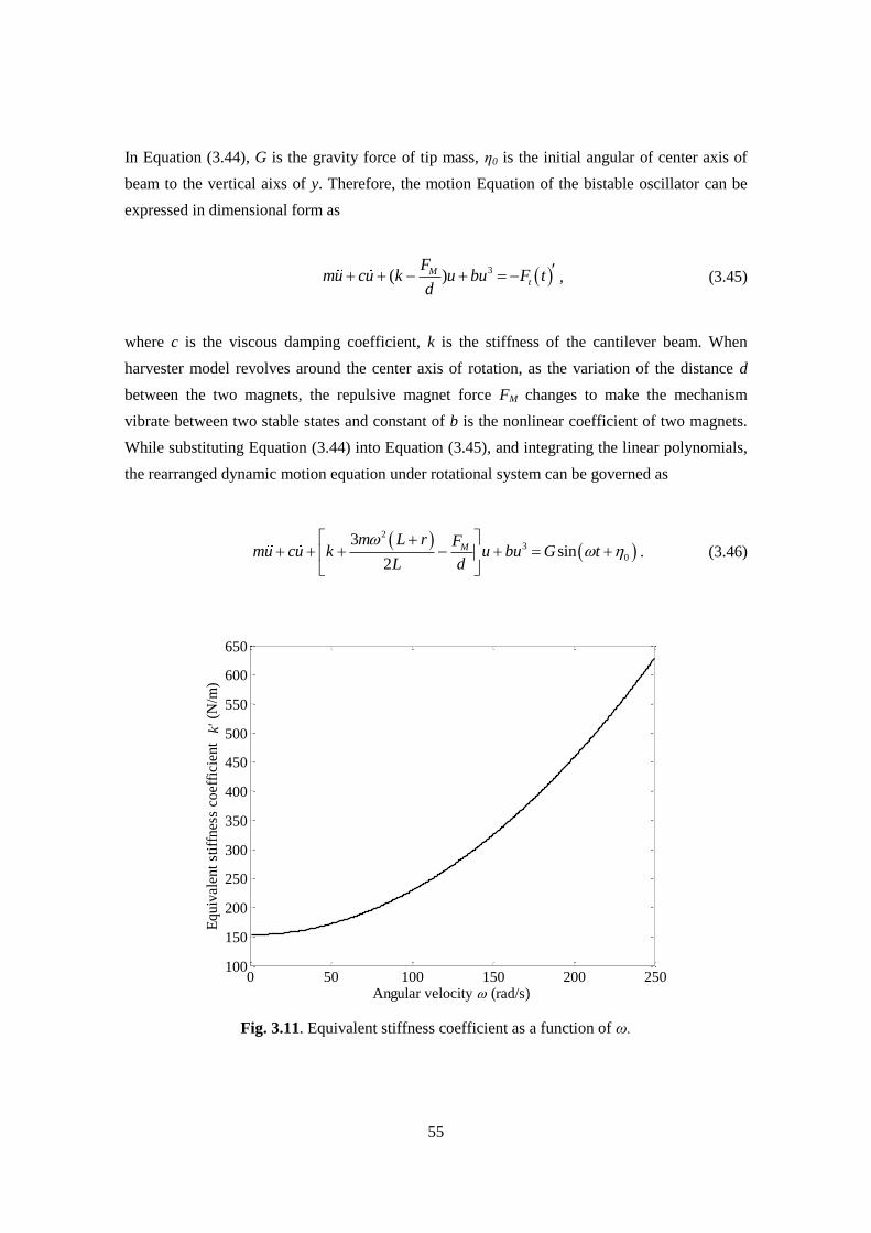
55
In Equation (3.44), G is the gravity force of tip mass, η0 is the initial angular of center axis of
beam to the vertical aixs of y. Therefore, the motion Equation of the bistable oscillator can be
expressed in dimensional form as
3( ) Mt
Fmu cu k u bu F t
d, (3.45)
where c is the viscous damping coefficient, k is the stiffness of the cantilever beam. When
harvester model revolves around the center axis of rotation, as the variation of the distance d
between the two magnets, the repulsive magnet force FM changes to make the mechanism
vibrate between two stable states and constant of b is the nonlinear coefficient of two magnets.
While substituting Equation (3.44) into Equation (3.45), and integrating the linear polynomials,
the rearranged dynamic motion equation under rotational system can be governed as
2
3
0
3sin
2
Mm L r F
mu cu k u bu G tL d
. (3.46)
Fig. 3.11. Equivalent stiffness coefficient as a function of ω.
0 50 100 150 200 250100
150
200
250
300
350
400
450
500
550
600
650
Angular velocity (rad/s)
Eq
uiv
alen
t st
iffn
ess
coef
fici
ent
k'
(N/m
)
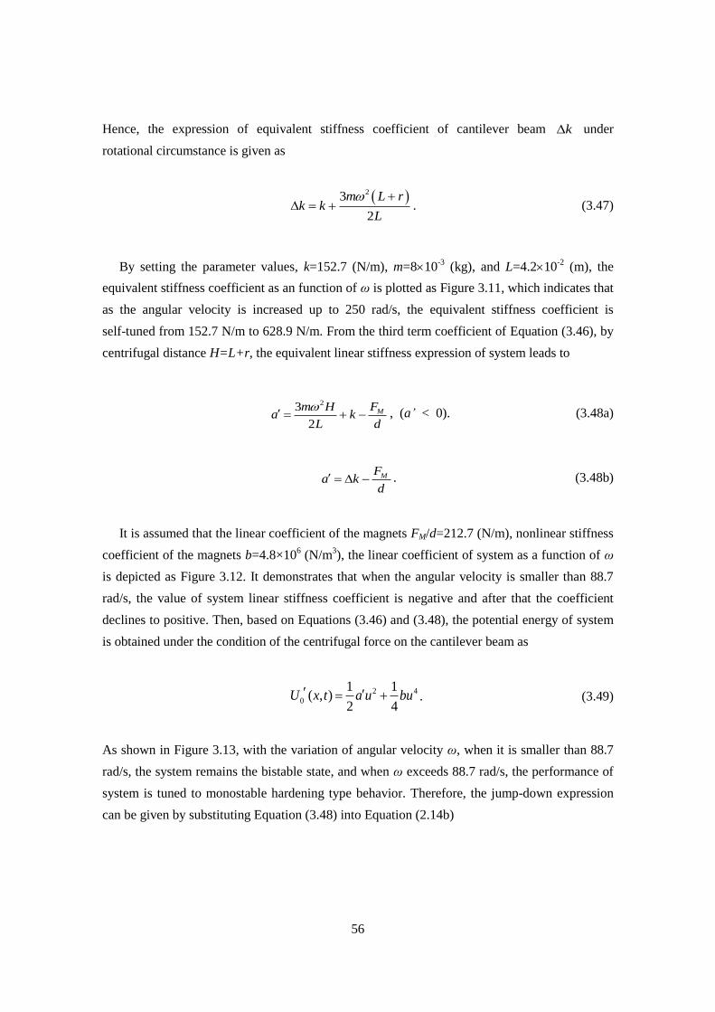
56
Hence, the expression of equivalent stiffness coefficient of cantilever beam k under
rotational circumstance is given as
23
2
m L rk k
L
. (3.47)
By setting the parameter values, k=152.7 (N/m), m=810-3
(kg), and L=4.210-2
(m), the
equivalent stiffness coefficient as an function of ω is plotted as Figure 3.11, which indicates that
as the angular velocity is increased up to 250 rad/s, the equivalent stiffness coefficient is
self-tuned from 152.7 N/m to 628.9 N/m. From the third term coefficient of Equation (3.46), by
centrifugal distance H=L+r, the equivalent linear stiffness expression of system leads to
23
2
MFm Ha k
L d
, (a’ < 0). (3.48a)
MFa k
d . (3.48b)
It is assumed that the linear coefficient of the magnets FM/d=212.7 (N/m), nonlinear stiffness
coefficient of the magnets b=4.8×10⁶ (N/m
3), the linear coefficient of system as a function of ω
is depicted as Figure 3.12. It demonstrates that when the angular velocity is smaller than 88.7
rad/s, the value of system linear stiffness coefficient is negative and after that the coefficient
declines to positive. Then, based on Equations (3.46) and (3.48), the potential energy of system
is obtained under the condition of the centrifugal force on the cantilever beam as
2 4
0
1 1( , )
2 4U x t a u bu . (3.49)
As shown in Figure 3.13, with the variation of angular velocity ω, when it is smaller than 88.7
rad/s, the system remains the bistable state, and when ω exceeds 88.7 rad/s, the performance of
system is tuned to monostable hardening type behavior. Therefore, the jump-down expression
can be given by substituting Equation (3.48) into Equation (2.14b)
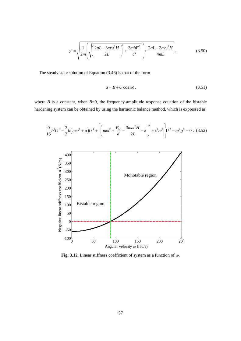
57
22 2 2
2
1 2 3 3 2 3
2 2 4
aL m H mbF aL m H
m L c mL
. (3.50)
The steady state solution of Equation (3.46) is that of the form
cosu B U t , (3.51)
where B is a constant, when B=0, the frequency-amplitude response equation of the bistable
hardening system can be obtained by using the harmonic balance method, which is expressed as
2
22 6 2 4 2 2 2 2 2 29 3 3
016 2 2
MF m Hb U b m a U m k c U m g
d L
. (3.52)
Fig. 3.12. Linear stiffness coefficient of system as a function of ω.
0 50 100 150 200 250-100
-50
0
50
100
150
200
250
300
350
400
Angular velocity (rad/s)
Neg
ativ
e li
nea
r st
iffn
ess
coef
fici
ent
-a (
N/m
)
Bistable region
Monotable region
0
a’
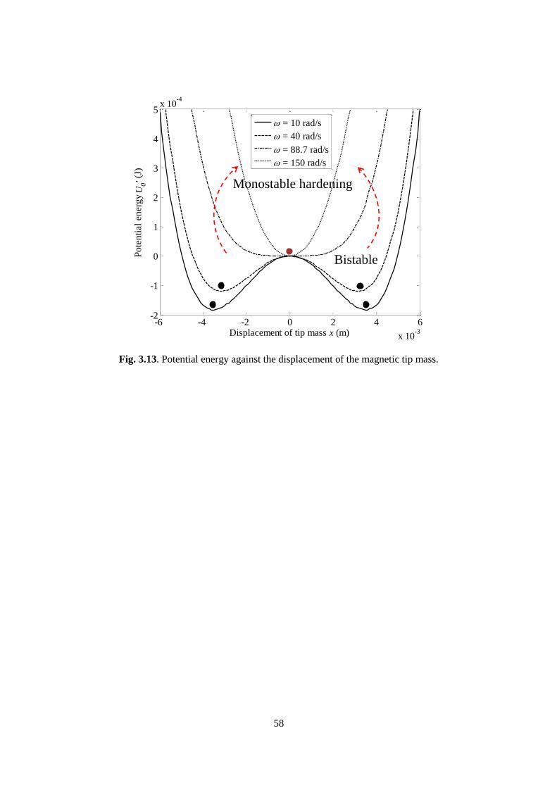
58
Fig. 3.13. Potential energy against the displacement of the magnetic tip mass.
-6 -4 -2 0 2 4 6
x 10-3
-2
-1
0
1
2
3
4
5x 10
-4
Displacement of tip mass x (m)
Po
ten
tial
en
erg
y U
0' (J
)
= 10 rad/s
= 40 rad/s
= 88.7 rad/s
= 150 rad/s
Bistable
Monostable hardening

59
Chapter 4
Numerical Analysis
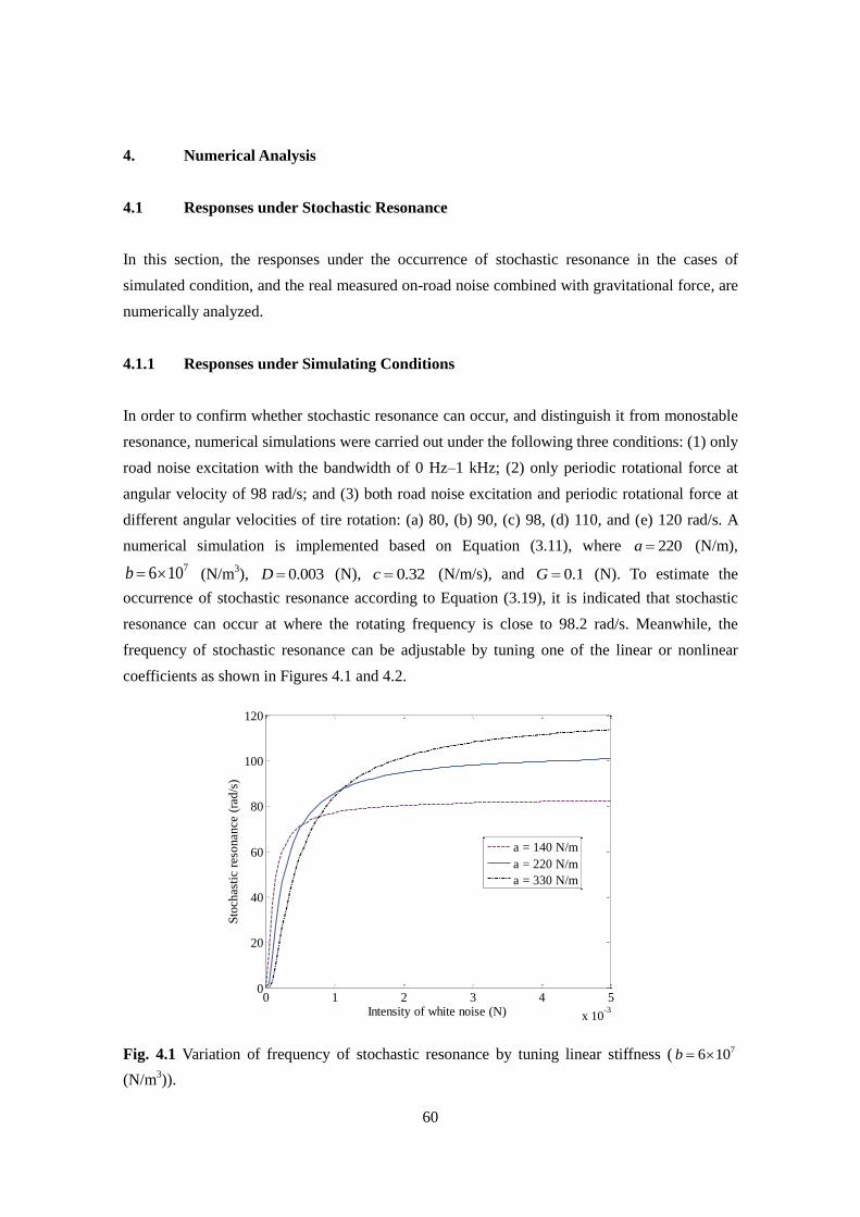
60
4. Numerical Analysis
4.1 Responses under Stochastic Resonance
In this section, the responses under the occurrence of stochastic resonance in the cases of
simulated condition, and the real measured on-road noise combined with gravitational force, are
numerically analyzed.
4.1.1 Responses under Simulating Conditions
In order to confirm whether stochastic resonance can occur, and distinguish it from monostable
resonance, numerical simulations were carried out under the following three conditions: (1) only
road noise excitation with the bandwidth of 0 Hz–1 kHz; (2) only periodic rotational force at
angular velocity of 98 rad/s; and (3) both road noise excitation and periodic rotational force at
different angular velocities of tire rotation: (a) 80, (b) 90, (c) 98, (d) 110, and (e) 120 rad/s. A
numerical simulation is implemented based on Equation (3.11), where 220a (N/m),
76 10b (N/m3), 0.003D (N), 0.32c (N/m/s), and 0.1G (N). To estimate the
occurrence of stochastic resonance according to Equation (3.19), it is indicated that stochastic
resonance can occur at where the rotating frequency is close to 98.2 rad/s. Meanwhile, the
frequency of stochastic resonance can be adjustable by tuning one of the linear or nonlinear
coefficients as shown in Figures 4.1 and 4.2.
Fig. 4.1 Variation of frequency of stochastic resonance by tuning linear stiffness ( 76 10b
(N/m3)).
0 1 2 3 4 5
x 10-3
0
20
40
60
80
100
120
Intensity of white noise (N)
Sto
chas
tic
reso
nan
ce (
rad
/s)
a = 140 N/m
a = 220 N/m
a = 330 N/m
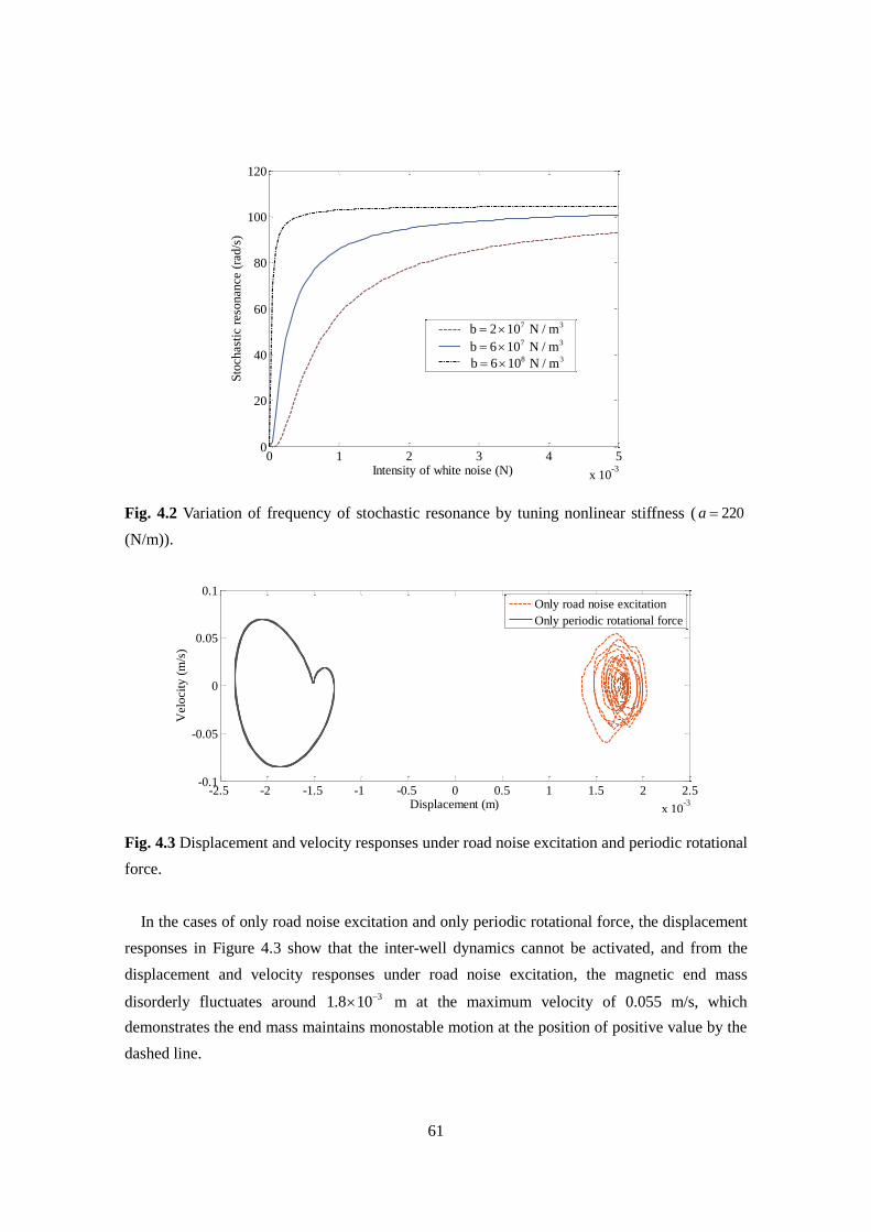
61
Fig. 4.2 Variation of frequency of stochastic resonance by tuning nonlinear stiffness ( 220a
(N/m)).
Fig. 4.3 Displacement and velocity responses under road noise excitation and periodic rotational
force.
In the cases of only road noise excitation and only periodic rotational force, the displacement
responses in Figure 4.3 show that the inter-well dynamics cannot be activated, and from the
displacement and velocity responses under road noise excitation, the magnetic end mass
disorderly fluctuates around 31.8 10 m at the maximum velocity of 0.055 m/s, which
demonstrates the end mass maintains monostable motion at the position of positive value by the
dashed line.
0 1 2 3 4 5
x 10-3
0
20
40
60
80
100
120
Intensity of white noise (N)
Sto
chas
tic
reso
nan
ce (
rad
/s)
7 3b 2 10 N / m 7 3b 6 10 N / m 8 3b 6 10 N / m
-2.5 -2 -1.5 -1 -0.5 0 0.5 1 1.5 2 2.5
x 10-3
-0.1
-0.05
0
0.05
0.1
Displacement (m)
Vel
oci
ty (
m/s
)
Only road noise excitation
Only periodic rotational force
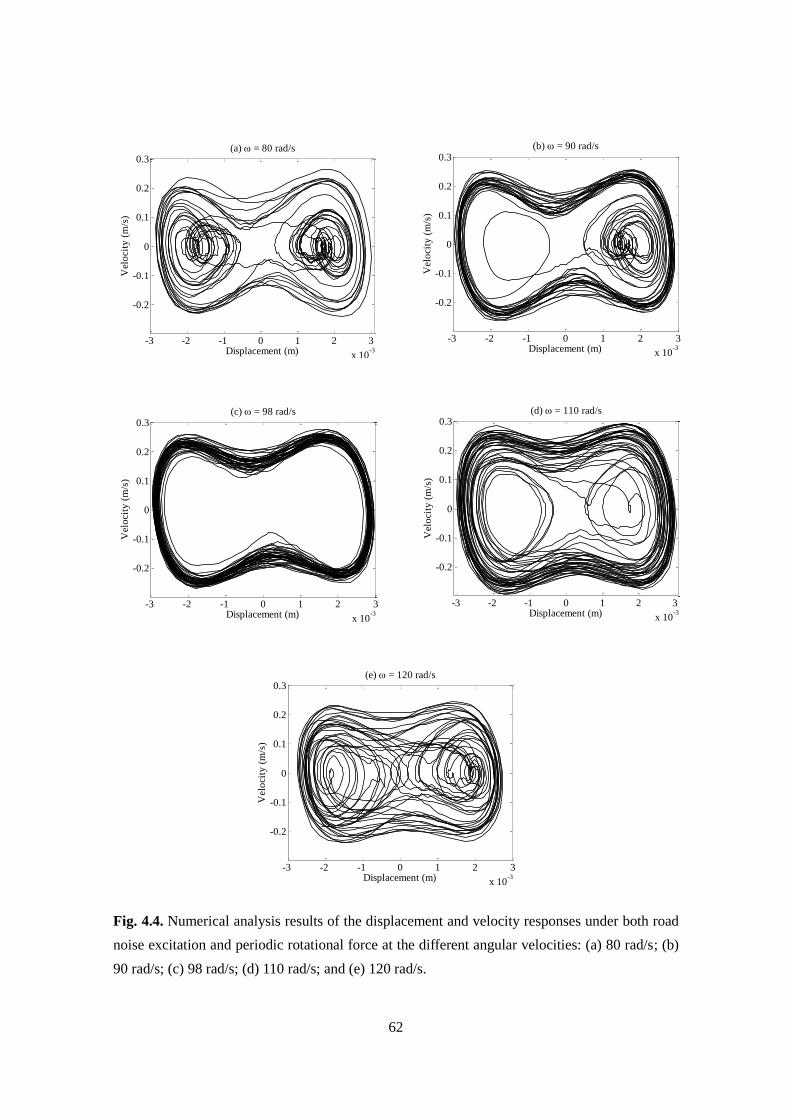
62
Fig. 4.4. Numerical analysis results of the displacement and velocity responses under both road
noise excitation and periodic rotational force at the different angular velocities: (a) 80 rad/s; (b)
90 rad/s; (c) 98 rad/s; (d) 110 rad/s; and (e) 120 rad/s.
-3 -2 -1 0 1 2 3
x 10-3
-0.2
-0.1
0
0.1
0.2
0.3
Displacement (m)
Vel
oci
ty (
m/s
)
(a) = 80 rad/s
-3 -2 -1 0 1 2 3
x 10-3
-0.2
-0.1
0
0.1
0.2
0.3
Displacement (m)
Vel
oci
ty (
m/s
)
(c) = 98 rad/s
-3 -2 -1 0 1 2 3
x 10-3
-0.2
-0.1
0
0.1
0.2
0.3
Displacement (m)
Vel
oci
ty (
m/s
)
(e) = 120 rad/s
-3 -2 -1 0 1 2 3
x 10-3
-0.2
-0.1
0
0.1
0.2
0.3
Displacement (m)
Vel
oci
ty (
m/s
)
(b) = 90 rad/s
-3 -2 -1 0 1 2 3
x 10-3
-0.2
-0.1
0
0.1
0.2
0.3
Displacement (m)
Vel
oci
ty (
m/s
)
(d) = 110 rad/s
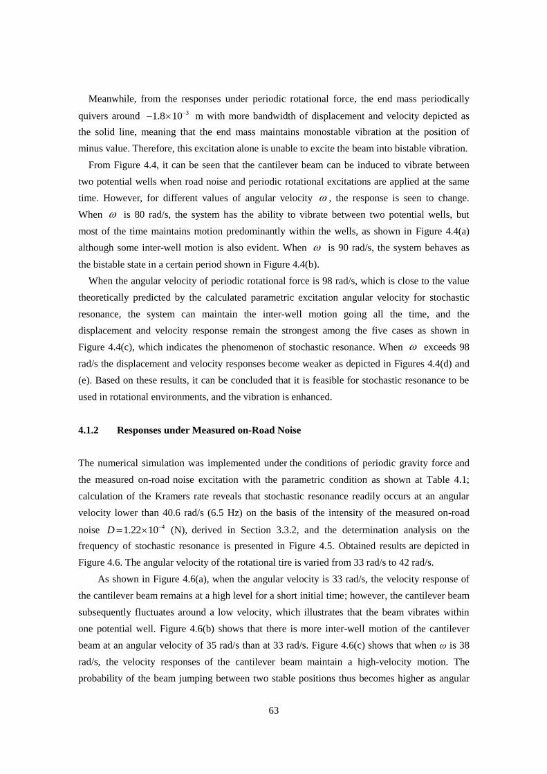
63
Meanwhile, from the responses under periodic rotational force, the end mass periodically
quivers around 31.8 10 m with more bandwidth of displacement and velocity depicted as
the solid line, meaning that the end mass maintains monostable vibration at the position of
minus value. Therefore, this excitation alone is unable to excite the beam into bistable vibration.
From Figure 4.4, it can be seen that the cantilever beam can be induced to vibrate between
two potential wells when road noise and periodic rotational excitations are applied at the same
time. However, for different values of angular velocity , the response is seen to change.
When is 80 rad/s, the system has the ability to vibrate between two potential wells, but
most of the time maintains motion predominantly within the wells, as shown in Figure 4.4(a)
although some inter-well motion is also evident. When is 90 rad/s, the system behaves as
the bistable state in a certain period shown in Figure 4.4(b).
When the angular velocity of periodic rotational force is 98 rad/s, which is close to the value
theoretically predicted by the calculated parametric excitation angular velocity for stochastic
resonance, the system can maintain the inter-well motion going all the time, and the
displacement and velocity response remain the strongest among the five cases as shown in
Figure 4.4(c), which indicates the phenomenon of stochastic resonance. When exceeds 98
rad/s the displacement and velocity responses become weaker as depicted in Figures 4.4(d) and
(e). Based on these results, it can be concluded that it is feasible for stochastic resonance to be
used in rotational environments, and the vibration is enhanced.
4.1.2 Responses under Measured on-Road Noise
The numerical simulation was implemented under the conditions of periodic gravity force and
the measured on-road noise excitation with the parametric condition as shown at Table 4.1;
calculation of the Kramers rate reveals that stochastic resonance readily occurs at an angular
velocity lower than 40.6 rad/s (6.5 Hz) on the basis of the intensity of the measured on-road
noise 41.22 10 D (N), derived in Section 3.3.2, and the determination analysis on the
frequency of stochastic resonance is presented in Figure 4.5. Obtained results are depicted in
Figure 4.6. The angular velocity of the rotational tire is varied from 33 rad/s to 42 rad/s.
As shown in Figure 4.6(a), when the angular velocity is 33 rad/s, the velocity response of
the cantilever beam remains at a high level for a short initial time; however, the cantilever beam
subsequently fluctuates around a low velocity, which illustrates that the beam vibrates within
one potential well. Figure 4.6(b) shows that there is more inter-well motion of the cantilever
beam at an angular velocity of 35 rad/s than at 33 rad/s. Figure 4.6(c) shows that when ω is 38
rad/s, the velocity responses of the cantilever beam maintain a high-velocity motion. The
probability of the beam jumping between two stable positions thus becomes higher as angular
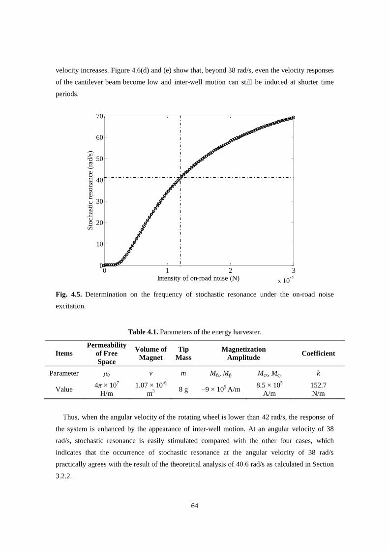
64
velocity increases. Figure 4.6(d) and (e) show that, beyond 38 rad/s, even the velocity responses
of the cantilever beam become low and inter-well motion can still be induced at shorter time
periods.
Fig. 4.5. Determination on the frequency of stochastic resonance under the on-road noise
excitation.
Table 4.1. Parameters of the energy harvester.
Items
Permeability
of Free
Space
Volume of
Magnet
Tip
Mass
Magnetization
Amplitude Coefficient
Parameter μ0 v m Mfx, Mfy Mcx, Mcy k
Value 4π × 10
7
H/m
1.07 × 10⁻⁶
m3
8 g –9 × 10⁵ A/m
8.5 × 10⁵
A/m
152.7
N/m
Thus, when the angular velocity of the rotating wheel is lower than 42 rad/s, the response of
the system is enhanced by the appearance of inter-well motion. At an angular velocity of 38
rad/s, stochastic resonance is easily stimulated compared with the other four cases, which
indicates that the occurrence of stochastic resonance at the angular velocity of 38 rad/s
practically agrees with the result of the theoretical analysis of 40.6 rad/s as calculated in Section
3.2.2.
0 1 2 3
x 10-4
0
10
20
30
40
50
60
70
Intensity of on-road noise (N)
Sto
chas
tic
reso
nan
ce (
rad/s
)
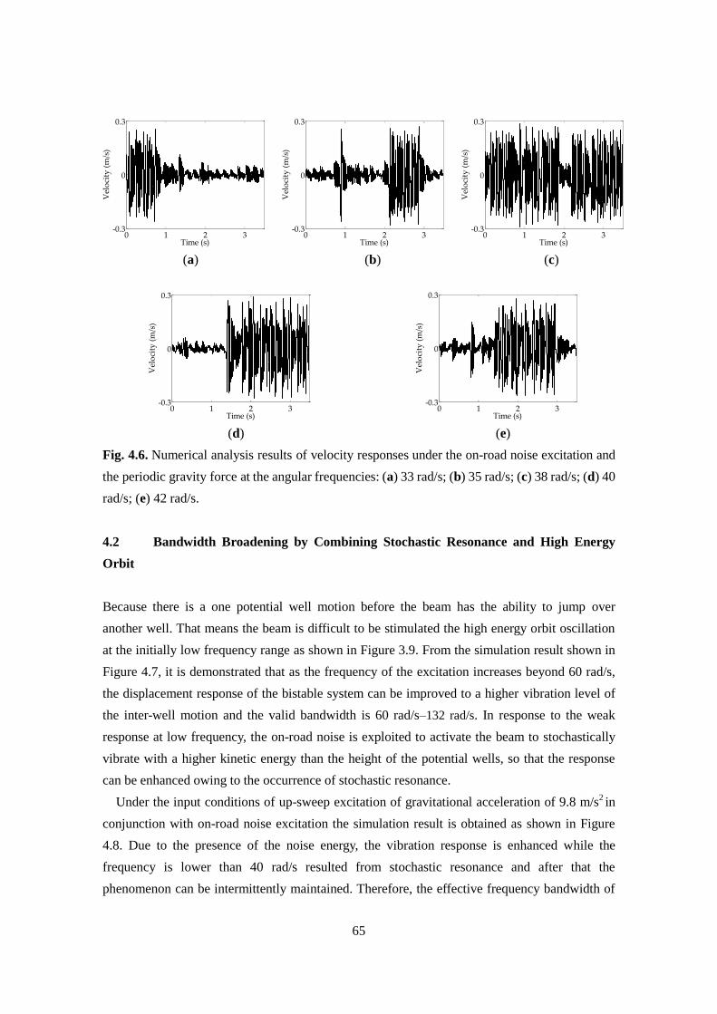
65
(a) (b) (c)
(d)
(e)
Fig. 4.6. Numerical analysis results of velocity responses under the on-road noise excitation and
the periodic gravity force at the angular frequencies: (a) 33 rad/s; (b) 35 rad/s; (c) 38 rad/s; (d) 40
rad/s; (e) 42 rad/s.
4.2 Bandwidth Broadening by Combining Stochastic Resonance and High Energy
Orbit
Because there is a one potential well motion before the beam has the ability to jump over
another well. That means the beam is difficult to be stimulated the high energy orbit oscillation
at the initially low frequency range as shown in Figure 3.9. From the simulation result shown in
Figure 4.7, it is demonstrated that as the frequency of the excitation increases beyond 60 rad/s,
the displacement response of the bistable system can be improved to a higher vibration level of
the inter-well motion and the valid bandwidth is 60 rad/s–132 rad/s. In response to the weak
response at low frequency, the on-road noise is exploited to activate the beam to stochastically
vibrate with a higher kinetic energy than the height of the potential wells, so that the response
can be enhanced owing to the occurrence of stochastic resonance.
Under the input conditions of up-sweep excitation of gravitational acceleration of 9.8 m/s2 in
conjunction with on-road noise excitation the simulation result is obtained as shown in Figure
4.8. Due to the presence of the noise energy, the vibration response is enhanced while the
frequency is lower than 40 rad/s resulted from stochastic resonance and after that the
phenomenon can be intermittently maintained. Therefore, the effective frequency bandwidth of
0 1 2 3-0.3
0
0.3
Time (s)
Vel
oci
ty (
m/s
)
0 1 2 3-0.3
0
0.3
Time (s)
Vel
oci
ty (
m/s
)
0 1 2 3-0.3
0
0.3
Time (s)
Vel
oci
ty (
m/s
)
0 1 2 3-0.3
0
0.3
Time (s)
Vel
oci
ty (
m/s
)
0 1 2 3-0.3
0
0.3
Time (s)V
elo
city
(m
/s)
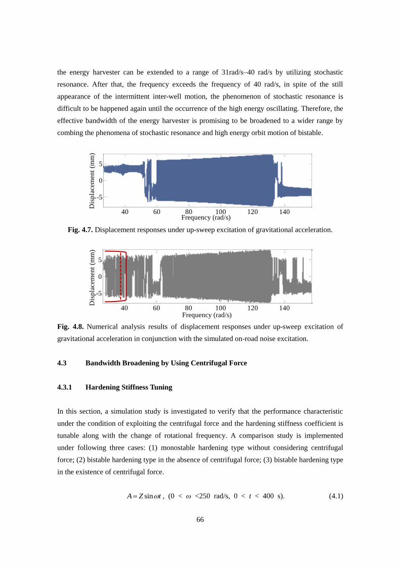
66
the energy harvester can be extended to a range of 31rad/s–40 rad/s by utilizing stochastic
resonance. After that, the frequency exceeds the frequency of 40 rad/s, in spite of the still
appearance of the intermittent inter-well motion, the phenomenon of stochastic resonance is
difficult to be happened again until the occurrence of the high energy oscillating. Therefore, the
effective bandwidth of the energy harvester is promising to be broadened to a wider range by
combing the phenomena of stochastic resonance and high energy orbit motion of bistable.
Fig. 4.7. Displacement responses under up-sweep excitation of gravitational acceleration.
Fig. 4.8. Numerical analysis results of displacement responses under up-sweep excitation of
gravitational acceleration in conjunction with the simulated on-road noise excitation.
4.3 Bandwidth Broadening by Using Centrifugal Force
4.3.1 Hardening Stiffness Tuning
In this section, a simulation study is investigated to verify that the performance characteristic
under the condition of exploiting the centrifugal force and the hardening stiffness coefficient is
tunable along with the change of rotational frequency. A comparison study is implemented
under following three cases: (1) monostable hardening type without considering centrifugal
force; (2) bistable hardening type in the absence of centrifugal force; (3) bistable hardening type
in the existence of centrifugal force.
sinA Z t , (0 < ω <250 rad/s, 0 < t < 400 s). (4.1)
40 60 80 100 120 140
-5
0
5
Frequency (rad/s)
Dis
pla
cem
ent
(mm
)
40 60 80 100 120 140
-5
0
5
Frequency (rad/s)
Dis
pla
cem
ent
(mm
)
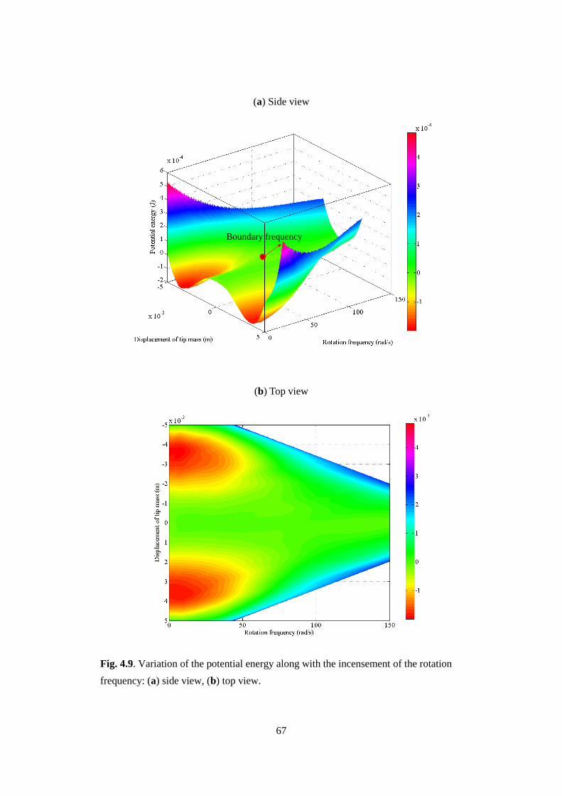
67
(a) Side view
(b) Top view
Fig. 4.9. Variation of the potential energy along with the incensement of the rotation
frequency: (a) side view, (b) top view.
Boundary frequency
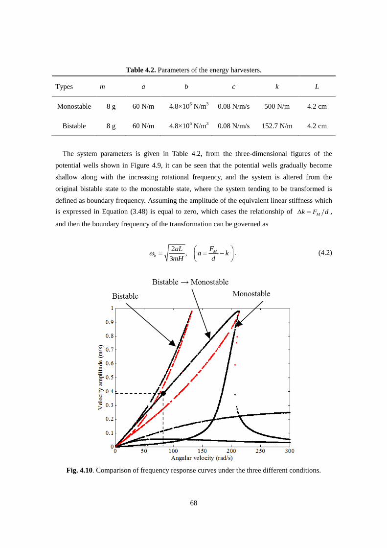
68
Table 4.2. Parameters of the energy harvesters.
Types m a b c k L
Monostable 8 g 60 N/m 4.8×10⁶ N/m
3 0.08 N/m/s 500 N/m 4.2 cm
Bistable 8 g 60 N/m 4.8×10⁶ N/m
3 0.08 N/m/s 152.7 N/m 4.2 cm
The system parameters is given in Table 4.2, from the three-dimensional figures of the
potential wells shown in Figure 4.9, it can be seen that the potential wells gradually become
shallow along with the increasing rotational frequency, and the system is altered from the
original bistable state to the monostable state, where the system tending to be transformed is
defined as boundary frequency. Assuming the amplitude of the equivalent linear stiffness which
is expressed in Equation (3.48) is equal to zero, which cases the relationship of Mk F d ,
and then the boundary frequency of the transformation can be governed as
2,
3
Mb
FaLa k
mH d . (4.2)
Fig. 4.10. Comparison of frequency response curves under the three different conditions.
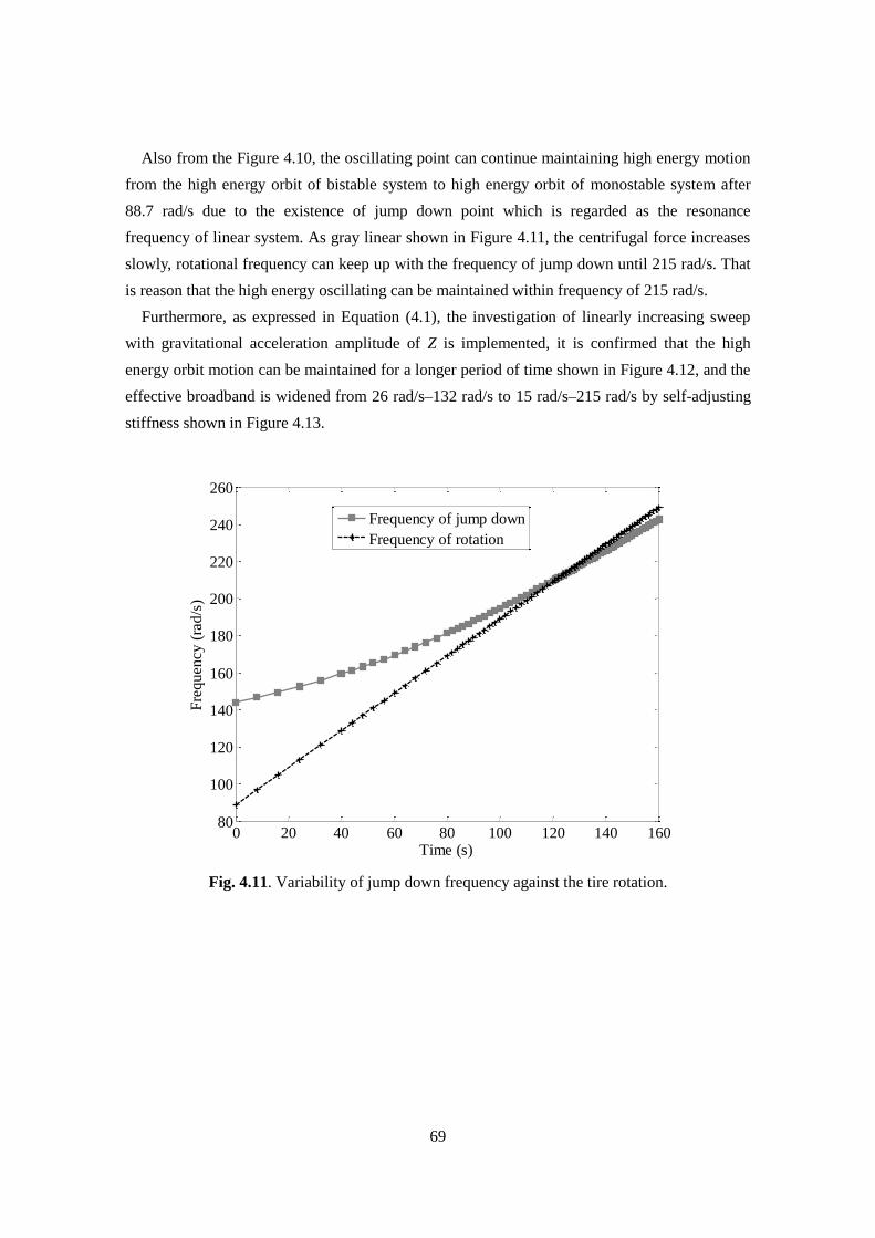
69
Also from the Figure 4.10, the oscillating point can continue maintaining high energy motion
from the high energy orbit of bistable system to high energy orbit of monostable system after
88.7 rad/s due to the existence of jump down point which is regarded as the resonance
frequency of linear system. As gray linear shown in Figure 4.11, the centrifugal force increases
slowly, rotational frequency can keep up with the frequency of jump down until 215 rad/s. That
is reason that the high energy oscillating can be maintained within frequency of 215 rad/s.
Furthermore, as expressed in Equation (4.1), the investigation of linearly increasing sweep
with gravitational acceleration amplitude of Z is implemented, it is confirmed that the high
energy orbit motion can be maintained for a longer period of time shown in Figure 4.12, and the
effective broadband is widened from 26 rad/s–132 rad/s to 15 rad/s–215 rad/s by self-adjusting
stiffness shown in Figure 4.13.
Fig. 4.11. Variability of jump down frequency against the tire rotation.
0 20 40 60 80 100 120 140 16080
100
120
140
160
180
200
220
240
260
Time (s)
Fre
quen
cy (
rad/s
)
Frequency of jump down
Frequency of rotation
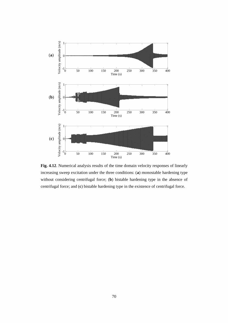
70
Fig. 4.12. Numerical analysis results of the time domain velocity responses of linearly
increasing sweep excitation under the three conditions: (a) monostable hardening type
without considering centrifugal force; (b) bistable hardening type in the absence of
centrifugal force; and (c) bistable hardening type in the existence of centrifugal force.
0 50 100 150 200 250 300 350 400-1
0
1
Time (s)Vel
oci
ty a
mpli
tude
(m/s
)
0 50 100 150 200 250 300 350 400-1
0
1
Time (s)Vel
oci
ty a
mpli
tude
(m/s
)
0 50 100 150 200 250 300 350 400-1
0
1
Time (s)Vel
oci
ty a
mpli
tude
(m/s
)(a)
(b)
(c)
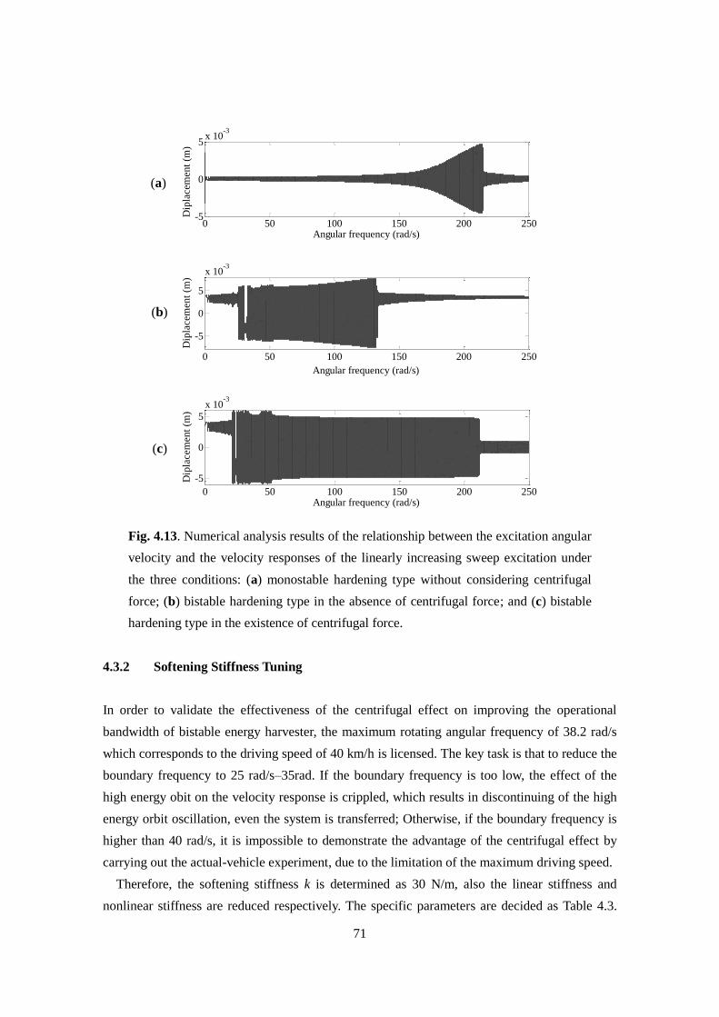
71
Fig. 4.13. Numerical analysis results of the relationship between the excitation angular
velocity and the velocity responses of the linearly increasing sweep excitation under
the three conditions: (a) monostable hardening type without considering centrifugal
force; (b) bistable hardening type in the absence of centrifugal force; and (c) bistable
hardening type in the existence of centrifugal force.
4.3.2 Softening Stiffness Tuning
In order to validate the effectiveness of the centrifugal effect on improving the operational
bandwidth of bistable energy harvester, the maximum rotating angular frequency of 38.2 rad/s
which corresponds to the driving speed of 40 km/h is licensed. The key task is that to reduce the
boundary frequency to 25 rad/s–35rad. If the boundary frequency is too low, the effect of the
high energy obit on the velocity response is crippled, which results in discontinuing of the high
energy orbit oscillation, even the system is transferred; Otherwise, if the boundary frequency is
higher than 40 rad/s, it is impossible to demonstrate the advantage of the centrifugal effect by
carrying out the actual-vehicle experiment, due to the limitation of the maximum driving speed.
Therefore, the softening stiffness k is determined as 30 N/m, also the linear stiffness and
nonlinear stiffness are reduced respectively. The specific parameters are decided as Table 4.3.
0 50 100 150 200 250-5
0
5x 10
-3
Angular frequency (rad/s)
Dip
lace
men
t (m
)
0 50 100 150 200 250
-5
0
5
x 10-3
Angular frequency (rad/s)
Dip
lace
men
t (m
)
0 50 100 150 200 250
-5
0
5
x 10-3
Angular frequency (rad/s)
Dip
lace
men
t (m
)(a)
(b)
(c)
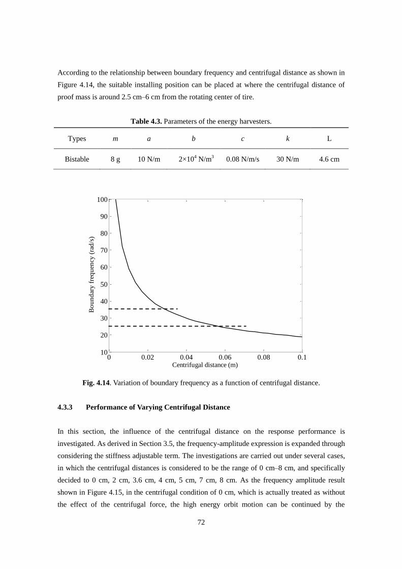
72
According to the relationship between boundary frequency and centrifugal distance as shown in
Figure 4.14, the suitable installing position can be placed at where the centrifugal distance of
proof mass is around 2.5 cm–6 cm from the rotating center of tire.
Table 4.3. Parameters of the energy harvesters.
Types m a b c k L
Bistable 8 g 10 N/m 2×10⁴ N/m
3 0.08 N/m/s 30 N/m 4.6 cm
Fig. 4.14. Variation of boundary frequency as a function of centrifugal distance.
4.3.3 Performance of Varying Centrifugal Distance
In this section, the influence of the centrifugal distance on the response performance is
investigated. As derived in Section 3.5, the frequency-amplitude expression is expanded through
considering the stiffness adjustable term. The investigations are carried out under several cases,
in which the centrifugal distances is considered to be the range of 0 cm–8 cm, and specifically
decided to 0 cm, 2 cm, 3.6 cm, 4 cm, 5 cm, 7 cm, 8 cm. As the frequency amplitude result
shown in Figure 4.15, in the centrifugal condition of 0 cm, which is actually treated as without
the effect of the centrifugal force, the high energy orbit motion can be continued by the
0 0.02 0.04 0.06 0.08 0.110
20
30
40
50
60
70
80
90
100
Centrifugal distance (m)
Bo
un
dar
y f
req
uen
cy (
rad
/s)
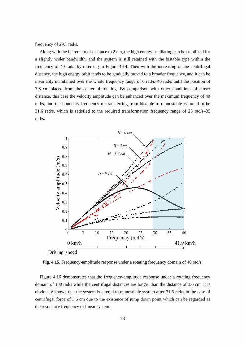
73
frequency of 29.1 rad/s.
Along with the increment of distance to 2 cm, the high energy oscillating can be stabilized for
a slightly wider bandwidth, and the system is still retained with the bistable type within the
frequency of 40 rad/s by referring to Figure 4.14. Then with the increasing of the centrifugal
distance, the high energy orbit tends to be gradually moved to a broader frequency, and it can be
invariably maintained over the whole frequency range of 0 rad/s–40 rad/s until the position of
3.6 cm placed from the center of rotating. By comparison with other conditions of closer
distance, this case the velocity amplitude can be enhanced over the maximum frequency of 40
rad/s, and the boundary frequency of transferring from bistable to monostable is found to be
31.6 rad/s, which is satisfied to the required transformation frequency range of 25 rad/s–35
rad/s.
Fig. 4.15. Frequency-amplitude response under a rotating frequency domain of 40 rad/s.
Figure 4.16 demonstrates that the frequency-amplitude response under a rotating frequency
domain of 100 rad/s while the centrifugal distances are longer than the distance of 3.6 cm. It is
obviously known that the system is altered to monostbale system after 31.6 rad/s in the case of
centrifugal force of 3.6 cm due to the existence of jump down point which can be regarded as
the resonance frequency of linear system.
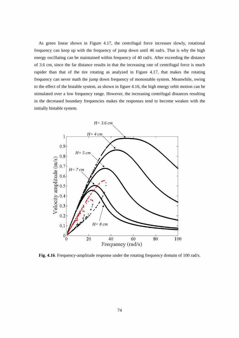
74
As green linear shown in Figure 4.17, the centrifugal force increases slowly, rotational
frequency can keep up with the frequency of jump down until 46 rad/s. That is why the high
energy oscillating can be maintained within frequency of 40 rad/s. After exceeding the distance
of 3.6 cm, since the far distance results in that the increasing rate of centrifugal force is much
rapider than that of the tire rotating as analyzed in Figure 4.17, that makes the rotating
frequency can never math the jump down frequency of monostable system. Meanwhile, owing
to the effect of the bistable system, as shown in figure 4.16, the high energy orbit motion can be
stimulated over a low frequency range. However, the increasing centrifugal distances resulting
in the decreased boundary frequencies makes the responses tend to become weaken with the
initially bistable system.
Fig. 4.16. Frequency-amplitude response under the rotating frequency domain of 100 rad/s.
H= 3.6 cm
H= 4 cm
H= 5 cm
H= 7 cm
H= 8 cm
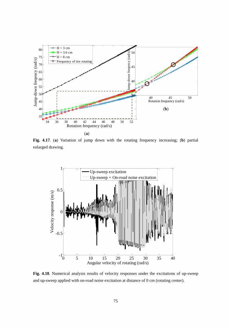
75
Fig. 4.17. (a) Variation of jump down with the rotating frequency increasing; (b) partial
enlarged drawing.
Fig. 4.18. Numerical analysis results of velocity responses under the excitations of up-sweep
and up-sweep applied with on-road noise excitation at distance of 0 cm (rotating center).
34 36 38 40 42 44 46 48 50 52
35
40
45
50
55
60
65
70
75
80
Rotation frequency (rad/s)
Jum
p-d
ow
n f
req
ency
(ra
d/s
)
H = 3 cm
H = 3.6 cm
H = 8 cm
Frequency of tire rotating
40 45 5035
40
45
50
Rotation frequency (rad/s)
Jum
p-d
ow
n f
req
ency
(ra
d/s
)
0 5 10 15 20 25 30 35 40-1
-0.5
0
0.5
1
Angular velocity of rotating (rad/s)
Velo
cit
y r
esp
onse
(m
/s)
Up-sweep excitation
Up-sweep + On-road noise excitation
(a)
(b)
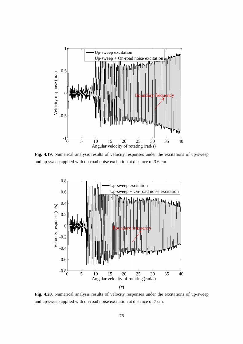
76
Fig. 4.19. Numerical analysis results of velocity responses under the excitations of up-sweep
and up-sweep applied with on-road noise excitation at distance of 3.6 cm.
(c)
Fig. 4.20. Numerical analysis results of velocity responses under the excitations of up-sweep
and up-sweep applied with on-road noise excitation at distance of 7 cm.
0 5 10 15 20 25 30 35 40-1
-0.5
0
0.5
1
Angular velocity of rotating (rad/s)
Velo
cit
y r
esp
on
se (
m/s
)
Up-sweep excitation
Up-sweep + On-road noise excitation
Boundary frequency
0 5 10 15 20 25 30 35 40-0.8
-0.6
-0.4
-0.2
0
0.2
0.4
0.6
0.8
Angular velocity of rotating (rad/s)
Velo
cit
y r
esp
on
se (
m/s
)
Up-sweep excitation
Up-sweep + On-road noise excitation
Boundary frequency
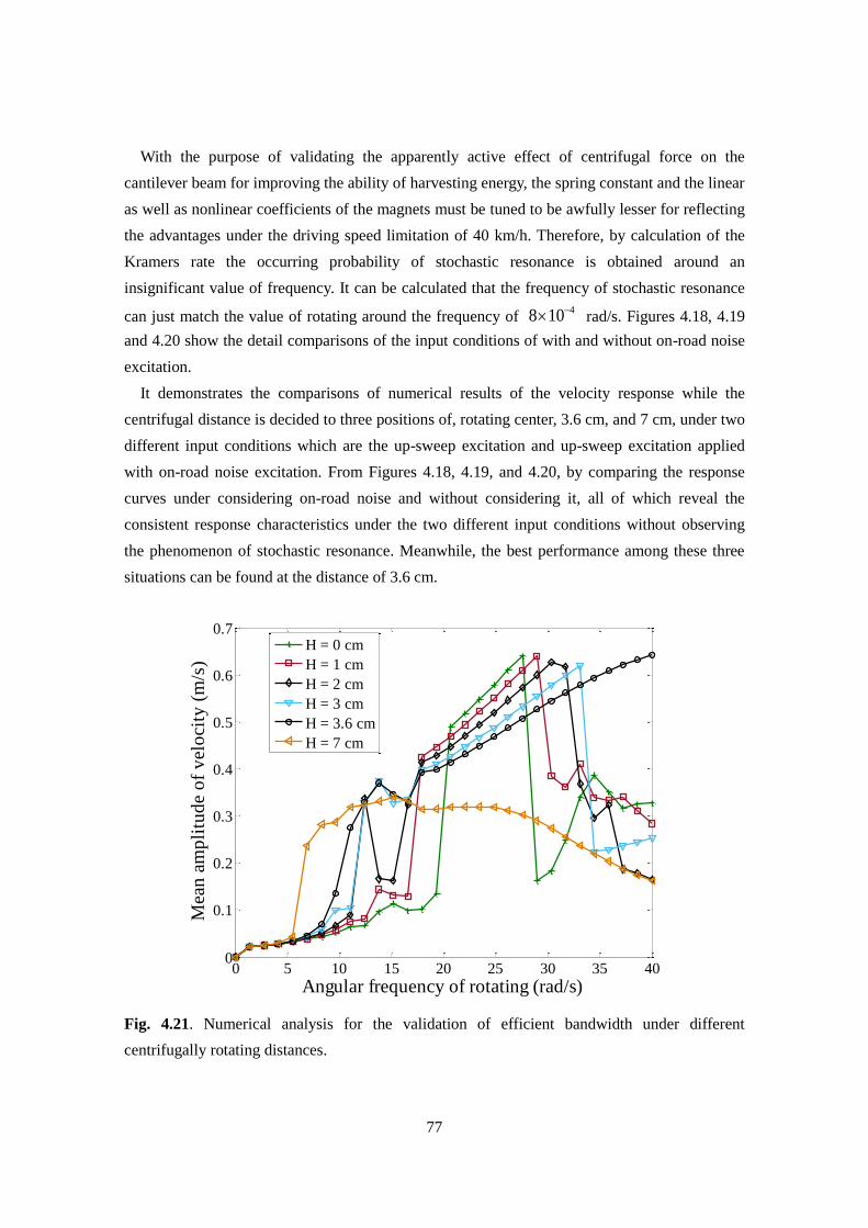
77
With the purpose of validating the apparently active effect of centrifugal force on the
cantilever beam for improving the ability of harvesting energy, the spring constant and the linear
as well as nonlinear coefficients of the magnets must be tuned to be awfully lesser for reflecting
the advantages under the driving speed limitation of 40 km/h. Therefore, by calculation of the
Kramers rate the occurring probability of stochastic resonance is obtained around an
insignificant value of frequency. It can be calculated that the frequency of stochastic resonance
can just match the value of rotating around the frequency of 48 10 rad/s. Figures 4.18, 4.19
and 4.20 show the detail comparisons of the input conditions of with and without on-road noise
excitation.
It demonstrates the comparisons of numerical results of the velocity response while the
centrifugal distance is decided to three positions of, rotating center, 3.6 cm, and 7 cm, under two
different input conditions which are the up-sweep excitation and up-sweep excitation applied
with on-road noise excitation. From Figures 4.18, 4.19, and 4.20, by comparing the response
curves under considering on-road noise and without considering it, all of which reveal the
consistent response characteristics under the two different input conditions without observing
the phenomenon of stochastic resonance. Meanwhile, the best performance among these three
situations can be found at the distance of 3.6 cm.
Fig. 4.21. Numerical analysis for the validation of efficient bandwidth under different
centrifugally rotating distances.
0 5 10 15 20 25 30 35 400
0.1
0.2
0.3
0.4
0.5
0.6
0.7
Angular frequency of rotating (rad/s)
Mea
n a
mp
litu
de
of
vel
oci
ty (
m/s
)
H = 0 cm
H = 1 cm
H = 2 cm
H = 3 cm
H = 3.6 cm
H = 7 cm

78
Furthermore, the simulation investigations of the mean velocity under different centrifugal
distances are performed. For each distance the simulations are carried out for thirty times,
therefore, one point represents one time implementation of system simulation and calculation of
the mean output velocity. By comparison of the different distances, the widest bandwidth is
found under the frequency range of 40 rad/s when it is adjusted to 3.6 cm as shown in Figure
4.21, which is very close to the result of frequency-amplitude curve as derived in Figure 4.15.
79
Chapter 5
Experimental Study
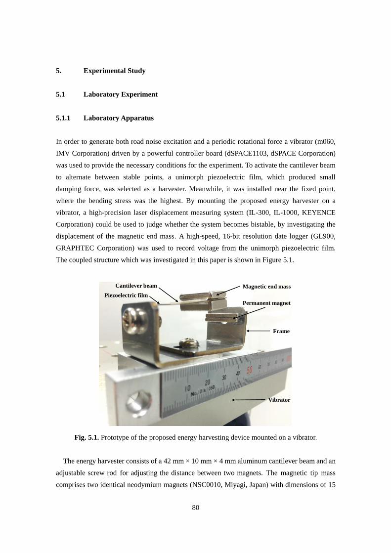
80
5. Experimental Study
5.1 Laboratory Experiment
5.1.1 Laboratory Apparatus
In order to generate both road noise excitation and a periodic rotational force a vibrator (m060,
IMV Corporation) driven by a powerful controller board (dSPACE1103, dSPACE Corporation)
was used to provide the necessary conditions for the experiment. To activate the cantilever beam
to alternate between stable points, a unimorph piezoelectric film, which produced small
damping force, was selected as a harvester. Meanwhile, it was installed near the fixed point,
where the bending stress was the highest. By mounting the proposed energy harvester on a
vibrator, a high-precision laser displacement measuring system (IL-300, IL-1000, KEYENCE
Corporation) could be used to judge whether the system becomes bistable, by investigating the
displacement of the magnetic end mass. A high-speed, 16-bit resolution date logger (GL900,
GRAPHTEC Corporation) was used to record voltage from the unimorph piezoelectric film.
The coupled structure which was investigated in this paper is shown in Figure 5.1.
Fig. 5.1. Prototype of the proposed energy harvesting device mounted on a vibrator.
The energy harvester consists of a 42 mm × 10 mm × 4 mm aluminum cantilever beam and an
adjustable screw rod for adjusting the distance between two magnets. The magnetic tip mass
comprises two identical neodymium magnets (NSC0010, Miyagi, Japan) with dimensions of 15
Magnetic end mass
Permanent magnet
Cantilever beam
Frame
Vibrator
Piezoelectric film
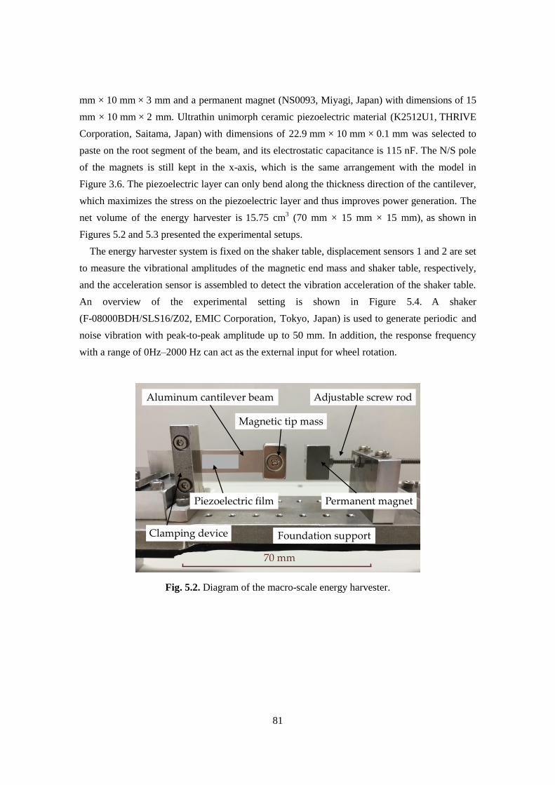
81
mm × 10 mm × 3 mm and a permanent magnet (NS0093, Miyagi, Japan) with dimensions of 15
mm × 10 mm × 2 mm. Ultrathin unimorph ceramic piezoelectric material (K2512U1, THRIVE
Corporation, Saitama, Japan) with dimensions of 22.9 mm × 10 mm × 0.1 mm was selected to
paste on the root segment of the beam, and its electrostatic capacitance is 115 nF. The N/S pole
of the magnets is still kept in the x-axis, which is the same arrangement with the model in
Figure 3.6. The piezoelectric layer can only bend along the thickness direction of the cantilever,
which maximizes the stress on the piezoelectric layer and thus improves power generation. The
net volume of the energy harvester is 15.75 cm3 (70 mm × 15 mm × 15 mm), as shown in
Figures 5.2 and 5.3 presented the experimental setups.
The energy harvester system is fixed on the shaker table, displacement sensors 1 and 2 are set
to measure the vibrational amplitudes of the magnetic end mass and shaker table, respectively,
and the acceleration sensor is assembled to detect the vibration acceleration of the shaker table.
An overview of the experimental setting is shown in Figure 5.4. A shaker
(F-08000BDH/SLS16/Z02, EMIC Corporation, Tokyo, Japan) is used to generate periodic and
noise vibration with peak-to-peak amplitude up to 50 mm. In addition, the response frequency
with a range of 0Hz–2000 Hz can act as the external input for wheel rotation.
Fig. 5.2. Diagram of the macro-scale energy harvester.
Aluminum cantilever beam
Magnetic tip mass
Permanent magnet
Adjustable screw rod
Clamping device Foundation support
Piezoelectric film
70 mm
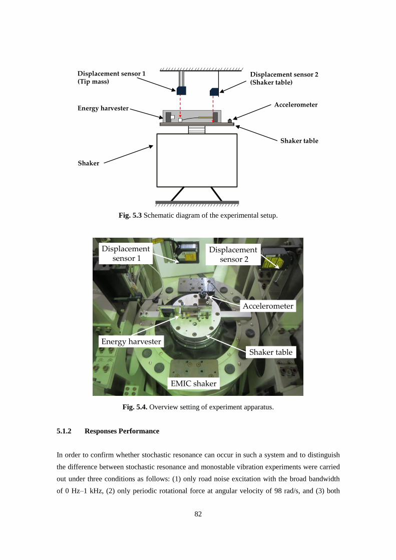
82
Fig. 5.3 Schematic diagram of the experimental setup.
Fig. 5.4. Overview setting of experiment apparatus.
5.1.2 Responses Performance
In order to confirm whether stochastic resonance can occur in such a system and to distinguish
the difference between stochastic resonance and monostable vibration experiments were carried
out under three conditions as follows: (1) only road noise excitation with the broad bandwidth
of 0 Hz–1 kHz, (2) only periodic rotational force at angular velocity of 98 rad/s, and (3) both
AccelerometerEnergy harvester
Displacement sensor 2(Shaker table)
Displacement sensor 1(Tip mass)
Shaker table
Shaker
Displacementsensor 2
Energy harvester
EMIC shaker
Accelerometer
Displacementsensor 1
Shaker table
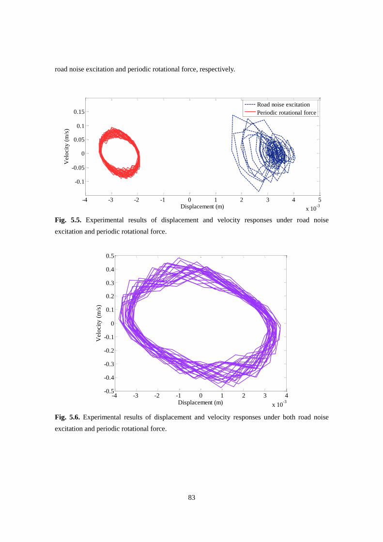
83
road noise excitation and periodic rotational force, respectively.
Fig. 5.5. Experimental results of displacement and velocity responses under road noise
excitation and periodic rotational force.
Fig. 5.6. Experimental results of displacement and velocity responses under both road noise
excitation and periodic rotational force.
-4 -3 -2 -1 0 1 2 3 4 5
x 10-3
-0.1
-0.05
0
0.05
0.1
0.15
Displacement (m)
Vel
oci
ty (
m/s
)
Road noise excitation
Periodic rotational force
-4 -3 -2 -1 0 1 2 3 4
x 10-3
-0.5
-0.4
-0.3
-0.2
-0.1
0
0.1
0.2
0.3
0.4
0.5
Displacement (m)
Vel
oci
ty (
m/s
)
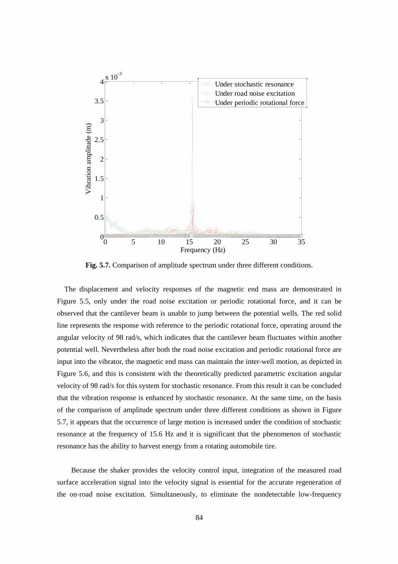
84
Fig. 5.7. Comparison of amplitude spectrum under three different conditions.
The displacement and velocity responses of the magnetic end mass are demonstrated in
Figure 5.5, only under the road noise excitation or periodic rotational force, and it can be
observed that the cantilever beam is unable to jump between the potential wells. The red solid
line represents the response with reference to the periodic rotational force, operating around the
angular velocity of 98 rad/s, which indicates that the cantilever beam fluctuates within another
potential well. Nevertheless after both the road noise excitation and periodic rotational force are
input into the vibrator, the magnetic end mass can maintain the inter-well motion, as depicted in
Figure 5.6, and this is consistent with the theoretically predicted parametric excitation angular
velocity of 98 rad/s for this system for stochastic resonance. From this result it can be concluded
that the vibration response is enhanced by stochastic resonance. At the same time, on the basis
of the comparison of amplitude spectrum under three different conditions as shown in Figure
5.7, it appears that the occurrence of large motion is increased under the condition of stochastic
resonance at the frequency of 15.6 Hz and it is significant that the phenomenon of stochastic
resonance has the ability to harvest energy from a rotating automobile tire.
Because the shaker provides the velocity control input, integration of the measured road
surface acceleration signal into the velocity signal is essential for the accurate regeneration of
the on-road noise excitation. Simultaneously, to eliminate the nondetectable low-frequency
0 5 10 15 20 25 30 350
0.5
1
1.5
2
2.5
3
3.5
4x 10
-3
Vib
rati
on a
mpli
tude
(m)
Frequency (Hz)
Under stochastic resonance
Under road noise excitation
Under periodic rotational force
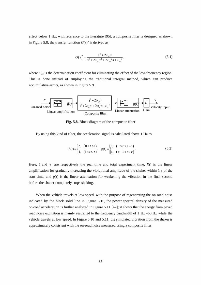
85
effect below 1 Hz, with reference to the literature [95], a composite filter is designed as shown
in Figure 5.8; the transfer function G(s)’ is derived as
2
3 2 2 3
2
2 2
cc
cc cc cc
s sG s
s s s
, (5.1)
where ωcc is the determination coefficient for eliminating the effect of the low-frequency region.
This is done instead of employing the traditional integral method, which can produce
accumulative errors, as shown in Figure 5.9.
Fig. 5.8. Block diagram of the composite filter
By using this kind of filter, the acceleration signal is calculated above 1 Hz as
, 0 1 1, 0 1( ) , ( )
1, 1 , 1
t t tf t g t
t t t
. (5.2)
Here, t and are respectively the real time and total experiment time, f(t) is the linear
amplification for gradually increasing the vibrational amplitude of the shaker within 1 s of the
start time, and g(t) is the linear attenuation for weakening the vibration in the final second
before the shaker completely stops shaking.
When the vehicle travels at low speed, with the purpose of regenerating the on-road noise
indicated by the black solid line in Figure 5.10, the power spectral density of the measured
on-road acceleration is further analyzed in Figure 5.11 [42]; it shows that the energy from paved
road noise excitation is mainly restricted to the frequency bandwidth of 1 Hz –60 Hz while the
vehicle travels at low speed. In Figure 5.10 and 5.11, the simulated vibration from the shaker is
approximately consistent with the on-road noise measured using a composite filter.
f(t)On-road noise
Linear amplification
2
3 2 2 3
2
2 2
cc
cc cc cc
s s
s s s
Linear attenuation GainVelocity input
Composite filter
aK
vg(t)
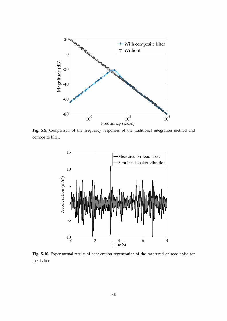
86
Fig. 5.9. Comparison of the frequency responses of the traditional integration method and
composite filter.
Fig. 5.10. Experimental results of acceleration regeneration of the measured on-road noise for
the shaker.
100
102
104
-80
-60
-40
-20
0
20
Frequency (rad/s)
Ma
gn
itu
de
(dB
)
With composite filter
Without
0 2 4 6 8-10
-5
0
5
10
15
Time (s)
Acc
ele
rati
on
(m
/s2)
Measured on-road noise
Simulated shaker vibration
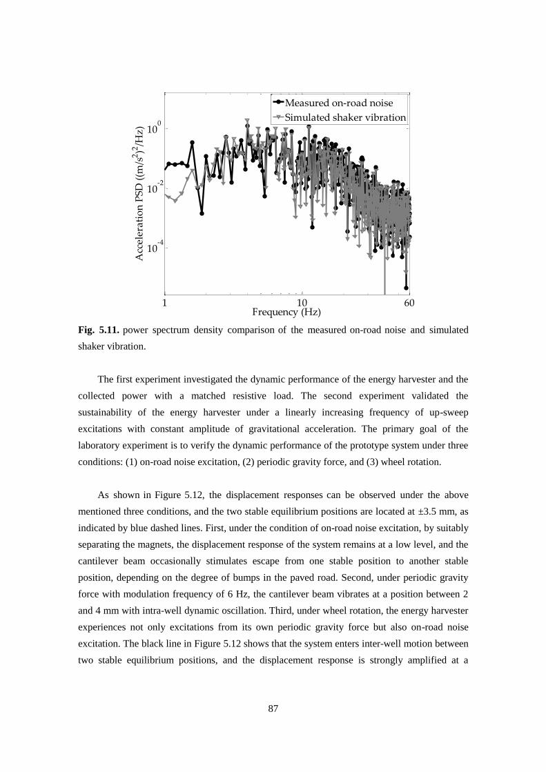
87
Fig. 5.11. power spectrum density comparison of the measured on-road noise and simulated
shaker vibration.
The first experiment investigated the dynamic performance of the energy harvester and the
collected power with a matched resistive load. The second experiment validated the
sustainability of the energy harvester under a linearly increasing frequency of up-sweep
excitations with constant amplitude of gravitational acceleration. The primary goal of the
laboratory experiment is to verify the dynamic performance of the prototype system under three
conditions: (1) on-road noise excitation, (2) periodic gravity force, and (3) wheel rotation.
As shown in Figure 5.12, the displacement responses can be observed under the above
mentioned three conditions, and the two stable equilibrium positions are located at ±3.5 mm, as
indicated by blue dashed lines. First, under the condition of on-road noise excitation, by suitably
separating the magnets, the displacement response of the system remains at a low level, and the
cantilever beam occasionally stimulates escape from one stable position to another stable
position, depending on the degree of bumps in the paved road. Second, under periodic gravity
force with modulation frequency of 6 Hz, the cantilever beam vibrates at a position between 2
and 4 mm with intra-well dynamic oscillation. Third, under wheel rotation, the energy harvester
experiences not only excitations from its own periodic gravity force but also on-road noise
excitation. The black line in Figure 5.12 shows that the system enters inter-well motion between
two stable equilibrium positions, and the displacement response is strongly amplified at a
1 10 60
10-4
10-2
100
Frequency (Hz)
Acc
eler
ati
on
PS
D (
(m/s
2)2
/Hz
)
Measured on-road noise
Simulated shaker vibration
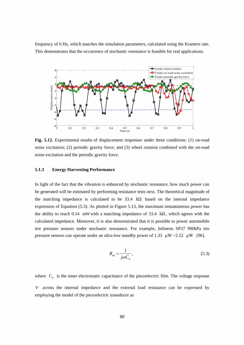
88
frequency of 6 Hz, which matches the simulation parameters, calculated using the Kramers rate.
This demonstrates that the occurrence of stochastic resonance is feasible for real applications.
Fig. 5.12. Experimental results of displacement responses under three conditions: (1) on-road
noise excitation; (2) periodic gravity force; and (3) wheel rotation combined with the on-road
noise excitation and the periodic gravity force.
5.1.3 Energy Harvesting Performance
In light of the fact that the vibration is enhanced by stochastic resonance, how much power can
be generated will be estimated by performing resistance tests next. The theoretical magnitude of
the matching impedance is calculated to be 33.4 kΩ based on the internal impedance
expression of Equation (5.3). As plotted in Figure 5.13, the maximum instantaneous power has
the ability to reach 0.14 mW with a matching impedance of 33.4 kΩ , which agrees with the
calculated impedance. Moreover, it is also demonstrated that it is possible to power automobile
tire pressure sensors under stochastic resonance. For example, Infineon SP37 900kPa tire
pressure sensors can operate under an ultra-low standby power of 1.33 μW ~2.52 μW [96].
1op
p
Rj C
, (5.3)
where pC is the inner electrostatic capacitance of the piezoelectric film. The voltage response
V across the internal impedance and the external load resistance can be expressed by
employing the model of the piezoelectric transducer as
5 0.1 0.2 0.3 0.4 0.5 0.6 0.7 0.8 0.9 1-8
-6
-4
-2
0
2
4
6
8
Time (s)
Dis
pla
cem
ent
(mm
)
Under wheel rotation
Under on-road noise excitation
Under periodic gravity force
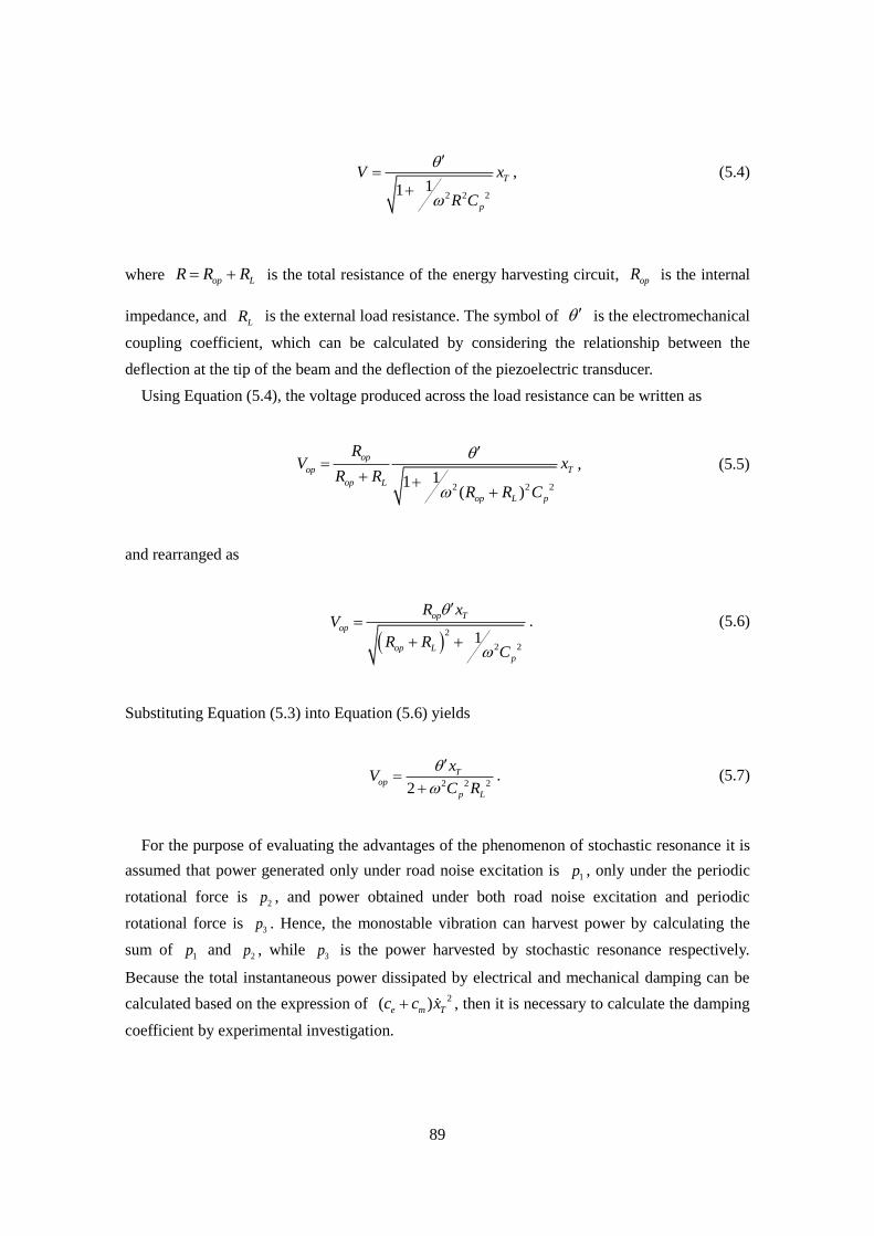
89
2 2 211
T
p
V x
R C
, (5.4)
where op LR R R is the total resistance of the energy harvesting circuit, opR is the internal
impedance, and LR is the external load resistance. The symbol of is the electromechanical
coupling coefficient, which can be calculated by considering the relationship between the
deflection at the tip of the beam and the deflection of the piezoelectric transducer.
Using Equation (5.4), the voltage produced across the load resistance can be written as
2 2 211
( )
op
op T
op L
op L p
RV x
R RR R C
, (5.5)
and rearranged as
2
2 21
op T
op
op Lp
R xV
R RC
. (5.6)
Substituting Equation (5.3) into Equation (5.6) yields
2 2 22
Top
p L
xV
C R
. (5.7)
For the purpose of evaluating the advantages of the phenomenon of stochastic resonance it is
assumed that power generated only under road noise excitation is 1p , only under the periodic
rotational force is 2p , and power obtained under both road noise excitation and periodic
rotational force is 3p . Hence, the monostable vibration can harvest power by calculating the
sum of 1p and
2p , while 3p is the power harvested by stochastic resonance respectively.
Because the total instantaneous power dissipated by electrical and mechanical damping can be
calculated based on the expression of 2( )e m Tc c x , then it is necessary to calculate the damping
coefficient by experimental investigation.
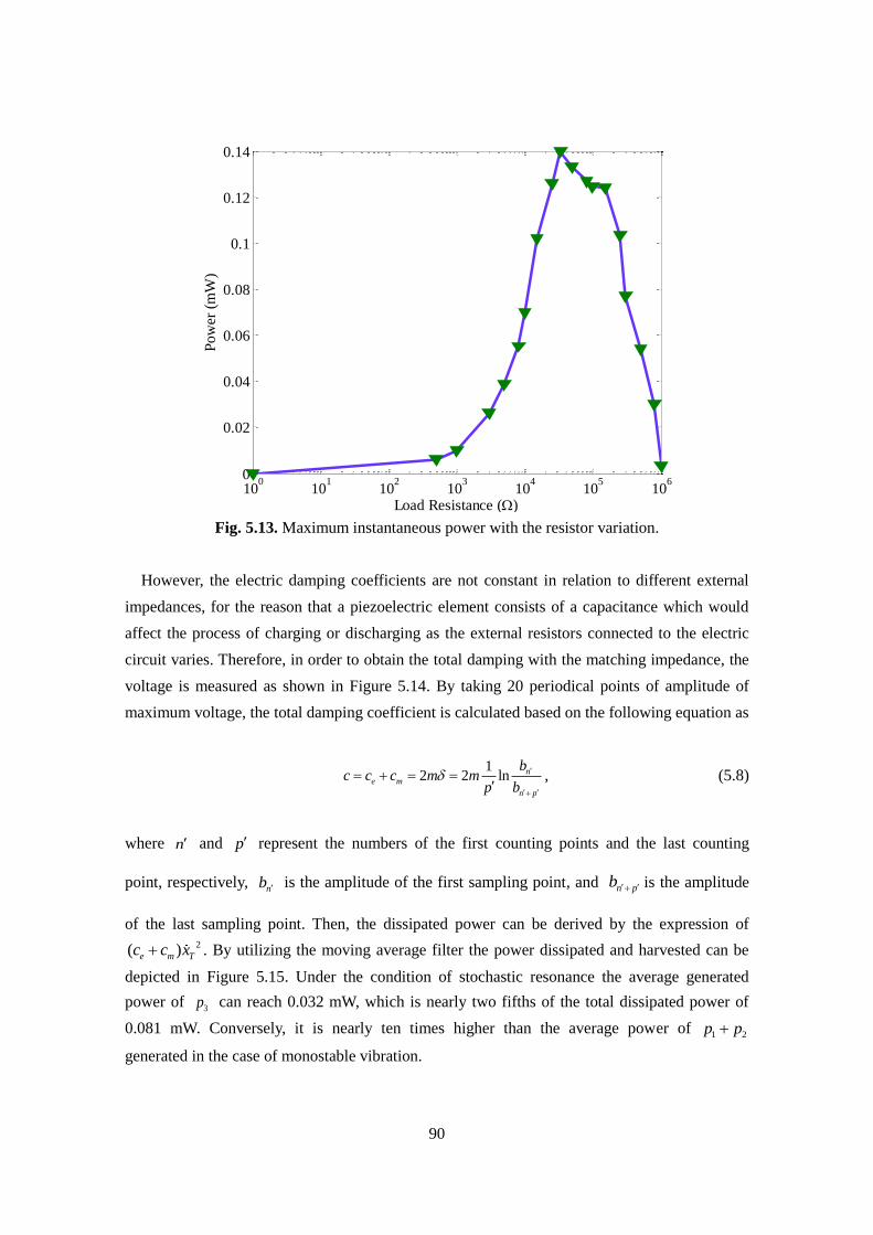
90
Fig. 5.13. Maximum instantaneous power with the resistor variation.
However, the electric damping coefficients are not constant in relation to different external
impedances, for the reason that a piezoelectric element consists of a capacitance which would
affect the process of charging or discharging as the external resistors connected to the electric
circuit varies. Therefore, in order to obtain the total damping with the matching impedance, the
voltage is measured as shown in Figure 5.14. By taking 20 periodical points of amplitude of
maximum voltage, the total damping coefficient is calculated based on the following equation as
12 2 ln n
e m
n p
bc c c m m
p b
, (5.8)
where n and p represent the numbers of the first counting points and the last counting
point, respectively, nb is the amplitude of the first sampling point, and n pb is the amplitude
of the last sampling point. Then, the dissipated power can be derived by the expression of
2( )e m Tc c x . By utilizing the moving average filter the power dissipated and harvested can be
depicted in Figure 5.15. Under the condition of stochastic resonance the average generated
power of 3p can reach 0.032 mW, which is nearly two fifths of the total dissipated power of
0.081 mW. Conversely, it is nearly ten times higher than the average power of 1 2p p
generated in the case of monostable vibration.
100
101
102
103
104
105
106
0
0.02
0.04
0.06
0.08
0.1
0.12
0.14
Load Resistance ()
Po
wer
(m
W)
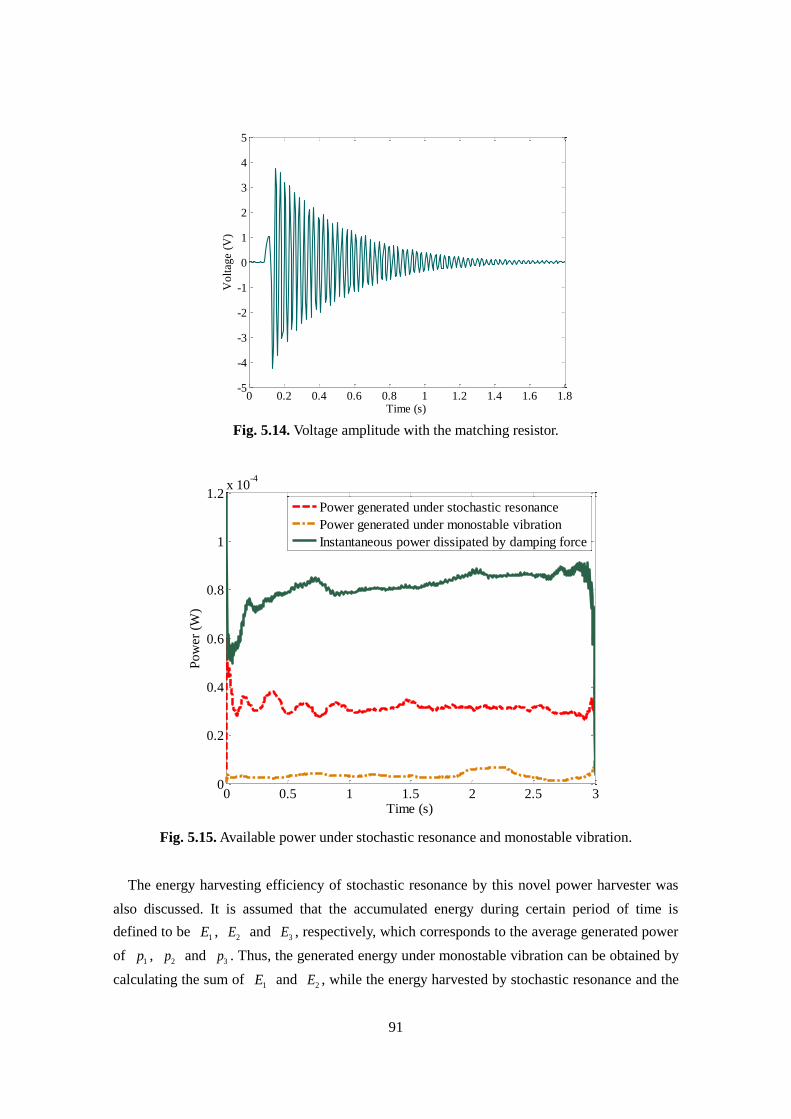
91
Fig. 5.14. Voltage amplitude with the matching resistor.
Fig. 5.15. Available power under stochastic resonance and monostable vibration.
The energy harvesting efficiency of stochastic resonance by this novel power harvester was
also discussed. It is assumed that the accumulated energy during certain period of time is
defined to be 1E ,
2E and 3E , respectively, which corresponds to the average generated power
of 1p ,
2p and 3p . Thus, the generated energy under monostable vibration can be obtained by
calculating the sum of 1E and
2E , while the energy harvested by stochastic resonance and the
0 0.2 0.4 0.6 0.8 1 1.2 1.4 1.6 1.8-5
-4
-3
-2
-1
0
1
2
3
4
5
Time (s)
Volt
age
(V)
0 0.5 1 1.5 2 2.5 30
0.2
0.4
0.6
0.8
1
1.2x 10
-4
Time (s)
Po
wer
(W
)
Power generated under stochastic resonance
Power generated under monostable vibration
Instantaneous power dissipated by damping force
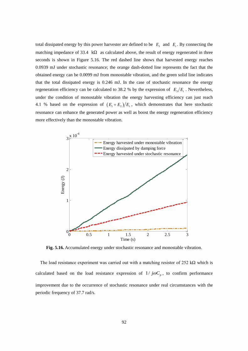
92
total dissipated energy by this power harvester are defined to be 3E and
tE . By connecting the
matching impedance of 33.4 kΩ as calculated above, the result of energy regenerated in three
seconds is shown in Figure 5.16. The red dashed line shows that harvested energy reaches
0.0939 mJ under stochastic resonance; the orange dash-dotted line represents the fact that the
obtained energy can be 0.0099 mJ from monostable vibration, and the green solid line indicates
that the total dissipated energy is 0.246 mJ. In the case of stochastic resonance the energy
regeneration efficiency can be calculated to 38.2 % by the expression of 3 tE E . Nevertheless,
under the condition of monostable vibration the energy harvesting efficiency can just reach
4.1 % based on the expression of 1 2 tE E E , which demonstrates that here stochastic
resonance can enhance the generated power as well as boost the energy regeneration efficiency
more effectively than the monostable vibration.
Fig. 5.16. Accumulated energy under stochastic resonance and monostable vibration.
The load resistance experiment was carried out with a matching resistor of 252 kΩ which is
calculated based on the load resistance expression of 1/ pj C , to confirm performance
improvement due to the occurrence of stochastic resonance under real circumstances with the
periodic frequency of 37.7 rad/s.
0 0.5 1 1.5 2 2.5 30
1
2
3x 10
-4
Time (s)
En
erg
y (
J)
Energy harvested under monostable vibration
Energy dissipated by damping force
Energy harvested under stochastic resonance
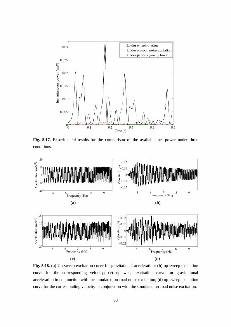
93
Fig. 5.17. Experimental results for the comparison of the available net power under three
conditions.
(a)
(b)
(c)
(d)
Fig. 5.18. (a) Up-sweep excitation curve for gravitational acceleration; (b) up-sweep excitation
curve for the corresponding velocity; (c) up-sweep excitation curve for gravitational
acceleration in conjunction with the simulated on-road noise excitation; (d) up-sweep excitation
curve for the corresponding velocity in conjunction with the simulated on-road noise excitation.
0 0.1 0.2 0.3 0.4 0.50
0.005
0.01
0.015
0.02
0.025
0.03
Time (s)
Inst
anta
neo
us
po
wer
(m
W)
Under wheel rotation
Under on-road noise excitation
Under periodic gravity force
5 6 7 8 9-20
-10
0
10
20
Frequency (Hz)
Acc
eler
atio
n (
m/s
2)
5 6 7 8 9
-0.02
-0.01
0
0.01
0.02
Frequency (Hz)
Vel
oci
ty (
m/s
)
5 6 7 8 9-20
-10
0
10
20
Frequency (Hz)
Acc
eler
atio
n (
m/s
2)
5 6 7 8 9
-0.02
-0.01
0
0.01
0.02
Frequency (Hz)
Vel
oci
ty (
m/s
)
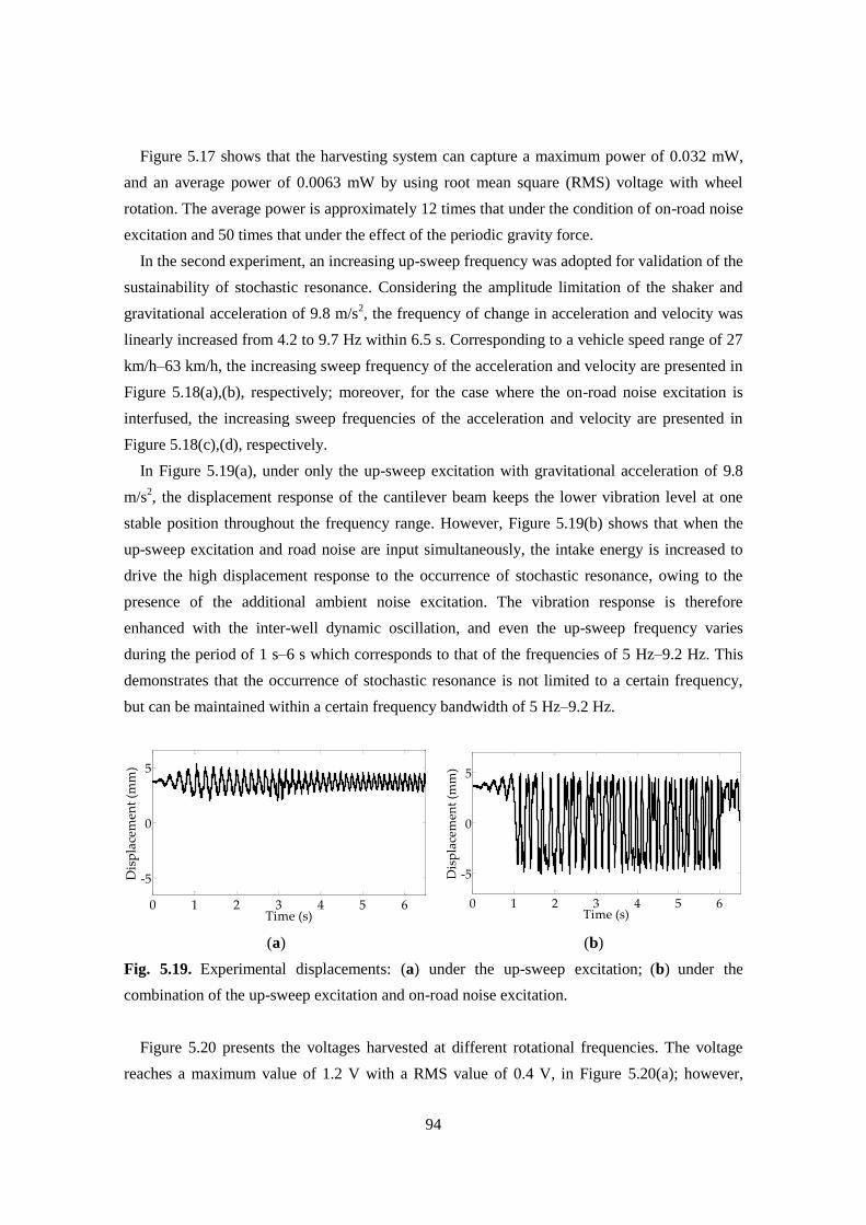
94
Figure 5.17 shows that the harvesting system can capture a maximum power of 0.032 mW,
and an average power of 0.0063 mW by using root mean square (RMS) voltage with wheel
rotation. The average power is approximately 12 times that under the condition of on-road noise
excitation and 50 times that under the effect of the periodic gravity force.
In the second experiment, an increasing up-sweep frequency was adopted for validation of the
sustainability of stochastic resonance. Considering the amplitude limitation of the shaker and
gravitational acceleration of 9.8 m/s2, the frequency of change in acceleration and velocity was
linearly increased from 4.2 to 9.7 Hz within 6.5 s. Corresponding to a vehicle speed range of 27
km/h–63 km/h, the increasing sweep frequency of the acceleration and velocity are presented in
Figure 5.18(a),(b), respectively; moreover, for the case where the on-road noise excitation is
interfused, the increasing sweep frequencies of the acceleration and velocity are presented in
Figure 5.18(c),(d), respectively.
In Figure 5.19(a), under only the up-sweep excitation with gravitational acceleration of 9.8
m/s2, the displacement response of the cantilever beam keeps the lower vibration level at one
stable position throughout the frequency range. However, Figure 5.19(b) shows that when the
up-sweep excitation and road noise are input simultaneously, the intake energy is increased to
drive the high displacement response to the occurrence of stochastic resonance, owing to the
presence of the additional ambient noise excitation. The vibration response is therefore
enhanced with the inter-well dynamic oscillation, and even the up-sweep frequency varies
during the period of 1 s–6 s which corresponds to that of the frequencies of 5 Hz–9.2 Hz. This
demonstrates that the occurrence of stochastic resonance is not limited to a certain frequency,
but can be maintained within a certain frequency bandwidth of 5 Hz–9.2 Hz.
(a)
(b)
Fig. 5.19. Experimental displacements: (a) under the up-sweep excitation; (b) under the
combination of the up-sweep excitation and on-road noise excitation.
Figure 5.20 presents the voltages harvested at different rotational frequencies. The voltage
reaches a maximum value of 1.2 V with a RMS value of 0.4 V, in Figure 5.20(a); however,
0 1 2 3 4 5 6
-5
0
5
Time (s)
Dis
pla
cem
ent
(mm
)
0 1 2 3 4 5 6
-5
0
5
Time (s)
Dis
pla
cem
ent
(mm
)
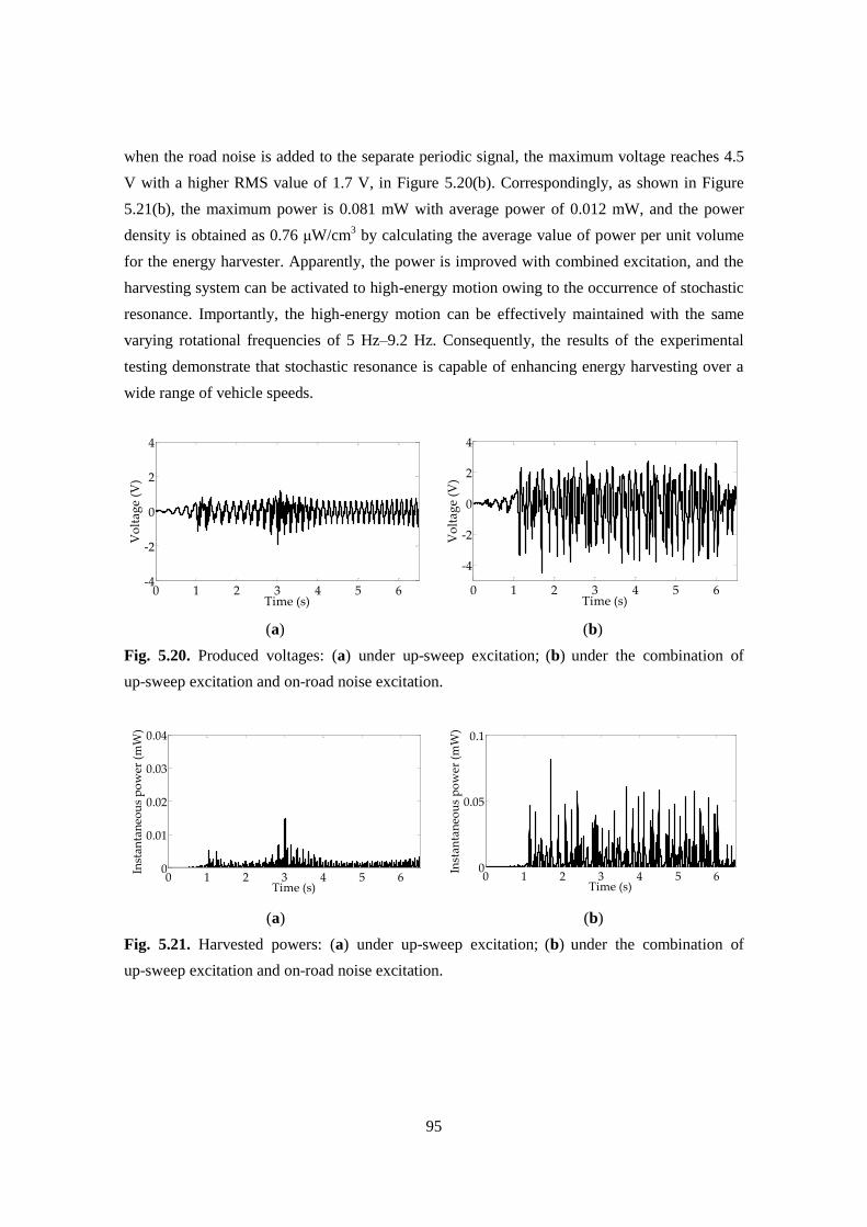
95
when the road noise is added to the separate periodic signal, the maximum voltage reaches 4.5
V with a higher RMS value of 1.7 V, in Figure 5.20(b). Correspondingly, as shown in Figure
5.21(b), the maximum power is 0.081 mW with average power of 0.012 mW, and the power
density is obtained as 0.76 μW/cm3 by calculating the average value of power per unit volume
for the energy harvester. Apparently, the power is improved with combined excitation, and the
harvesting system can be activated to high-energy motion owing to the occurrence of stochastic
resonance. Importantly, the high-energy motion can be effectively maintained with the same
varying rotational frequencies of 5 Hz–9.2 Hz. Consequently, the results of the experimental
testing demonstrate that stochastic resonance is capable of enhancing energy harvesting over a
wide range of vehicle speeds.
(a)
(b)
Fig. 5.20. Produced voltages: (a) under up-sweep excitation; (b) under the combination of
up-sweep excitation and on-road noise excitation.
(a)
(b)
Fig. 5.21. Harvested powers: (a) under up-sweep excitation; (b) under the combination of
up-sweep excitation and on-road noise excitation.
0 1 2 3 4 5 6-4
-2
0
2
4
Time (s)
Vo
lta
ge
(V)
0 1 2 3 4 5 6
-4
-2
0
2
4
Time (s)
Vo
lta
ge
(V)
0 1 2 3 4 5 60
0.01
0.02
0.03
0.04
Time (s)
Inst
an
tan
eou
s p
ow
er (
mW
)
0 1 2 3 4 5 60
0.05
0.1
Time (s)
Inst
an
tan
eou
s p
ow
er (
mW
)
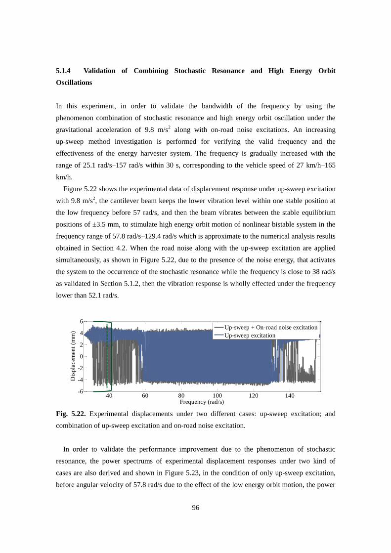
96
5.1.4 Validation of Combining Stochastic Resonance and High Energy Orbit
Oscillations
In this experiment, in order to validate the bandwidth of the frequency by using the
phenomenon combination of stochastic resonance and high energy orbit oscillation under the
gravitational acceleration of 9.8 m/s2 along with on-road noise excitations. An increasing
up-sweep method investigation is performed for verifying the valid frequency and the
effectiveness of the energy harvester system. The frequency is gradually increased with the
range of 25.1 rad/s–157 rad/s within 30 s, corresponding to the vehicle speed of 27 km/h–165
km/h.
Figure 5.22 shows the experimental data of displacement response under up-sweep excitation
with 9.8 m/s2, the cantilever beam keeps the lower vibration level within one stable position at
the low frequency before 57 rad/s, and then the beam vibrates between the stable equilibrium
positions of ±3.5 mm, to stimulate high energy orbit motion of nonlinear bistable system in the
frequency range of 57.8 rad/s–129.4 rad/s which is approximate to the numerical analysis results
obtained in Section 4.2. When the road noise along with the up-sweep excitation are applied
simultaneously, as shown in Figure 5.22, due to the presence of the noise energy, that activates
the system to the occurrence of the stochastic resonance while the frequency is close to 38 rad/s
as validated in Section 5.1.2, then the vibration response is wholly effected under the frequency
lower than 52.1 rad/s.
Fig. 5.22. Experimental displacements under two different cases: up-sweep excitation; and
combination of up-sweep excitation and on-road noise excitation.
In order to validate the performance improvement due to the phenomenon of stochastic
resonance, the power spectrums of experimental displacement responses under two kind of
cases are also derived and shown in Figure 5.23, in the condition of only up-sweep excitation,
before angular velocity of 57.8 rad/s due to the effect of the low energy orbit motion, the power
40 60 80 100 120 140-6
-4
-2
0
2
4
6
Frequency (rad/s)
Dis
pla
cem
ent
(mm
)
Up-sweep + On-road noise excitation
Up-sweep excitation
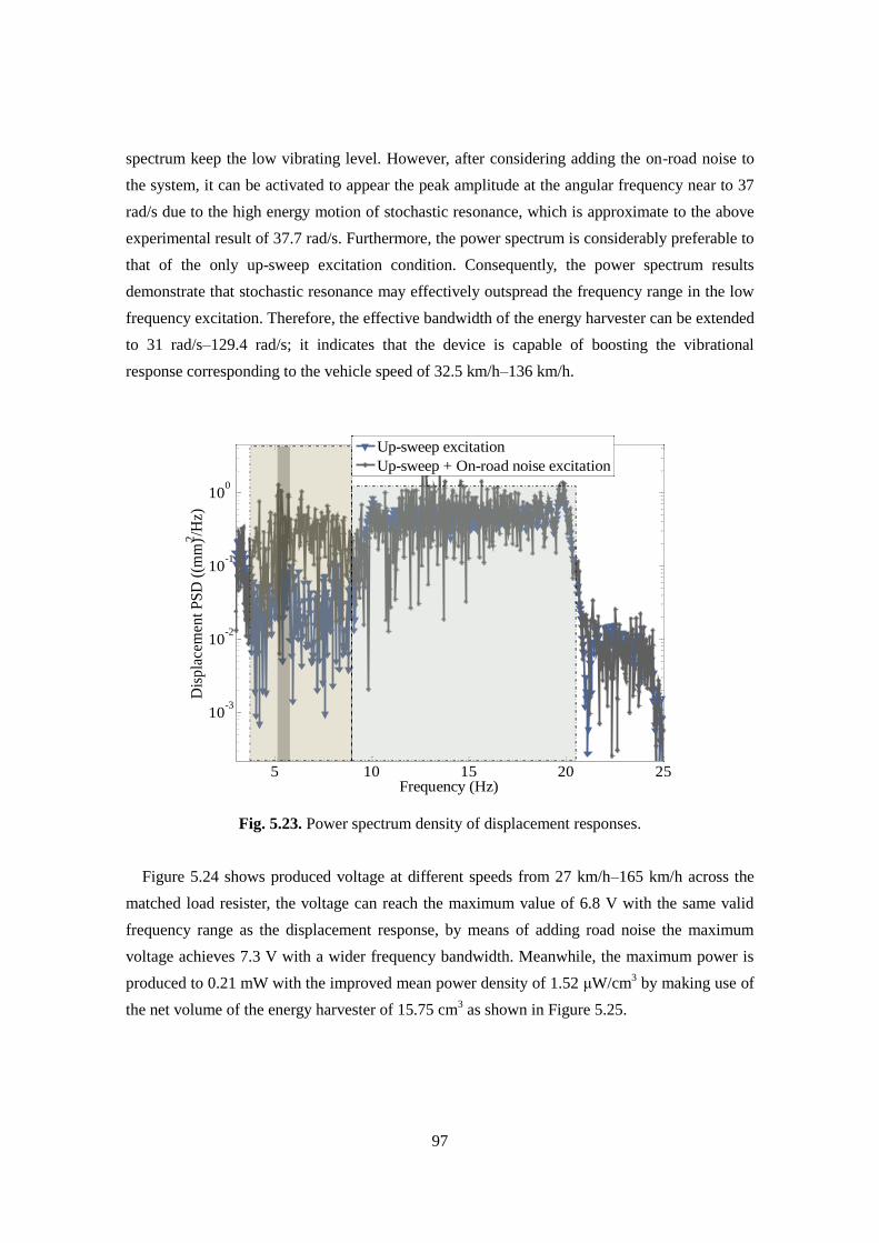
97
spectrum keep the low vibrating level. However, after considering adding the on-road noise to
the system, it can be activated to appear the peak amplitude at the angular frequency near to 37
rad/s due to the high energy motion of stochastic resonance, which is approximate to the above
experimental result of 37.7 rad/s. Furthermore, the power spectrum is considerably preferable to
that of the only up-sweep excitation condition. Consequently, the power spectrum results
demonstrate that stochastic resonance may effectively outspread the frequency range in the low
frequency excitation. Therefore, the effective bandwidth of the energy harvester can be extended
to 31 rad/s–129.4 rad/s; it indicates that the device is capable of boosting the vibrational
response corresponding to the vehicle speed of 32.5 km/h–136 km/h.
Fig. 5.23. Power spectrum density of displacement responses.
Figure 5.24 shows produced voltage at different speeds from 27 km/h–165 km/h across the
matched load resister, the voltage can reach the maximum value of 6.8 V with the same valid
frequency range as the displacement response, by means of adding road noise the maximum
voltage achieves 7.3 V with a wider frequency bandwidth. Meanwhile, the maximum power is
produced to 0.21 mW with the improved mean power density of 1.52 μW/cm3 by making use of
the net volume of the energy harvester of 15.75 cm3 as shown in Figure 5.25.
5 10 15 20 25
10-3
10-2
10-1
100
Frequency (Hz)
Dis
pla
cem
ent
PS
D (
(mm
)2/H
z)
Up-sweep excitation
Up-sweep + On-road noise excitation
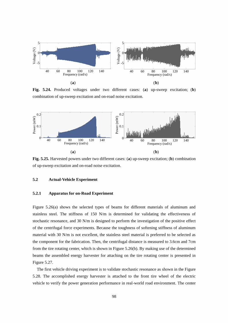
98
(a) (b)
Fig. 5.24. Produced voltages under two different cases: (a) up-sweep excitation; (b)
combination of up-sweep excitation and on-road noise excitation.
(a) (b)
Fig. 5.25. Harvested powers under two different cases: (a) up-sweep excitation; (b) combination
of up-sweep excitation and on-road noise excitation.
5.2 Actual-Vehicle Experiment
5.2.1 Apparatus for on-Road Experiment
Figure 5.26(a) shows the selected types of beams for different materials of aluminum and
stainless steel. The stiffness of 150 N/m is determined for validating the effectiveness of
stochastic resonance, and 30 N/m is designed to perform the investigation of the positive effect
of the centrifugal force experiments. Because the toughness of softening stiffness of aluminum
material with 30 N/m is not excellent, the stainless steel material is preferred to be selected as
the component for the fabrication. Then, the centrifugal distance is measured to 3.6cm and 7cm
from the tire rotating center, which is shown in Figure 5.26(b). By making use of the determined
beams the assembled energy harvester for attaching on the tire rotating center is presented in
Figure 5.27.
The first vehicle driving experiment is to validate stochastic resonance as shown in the Figure
5.28. The accomplished energy harvester is attached to the front tire wheel of the electric
vehicle to verify the power generation performance in real-world road environment. The center
40 60 80 100 120 140
-5
0
5
Frequency (rad/s)
Volt
age
(V)
40 60 80 100 120 1400
0.1
0.2
Frequency (rad/s)
Pow
er (
mW
)
40 60 80 100 120 140
-5
0
5
Frequency (rad/s)
Vo
ltag
e (V
)
40 60 80 100 120 1400
0.1
0.2
Frequency (rad/s)
Po
wer
(m
W)
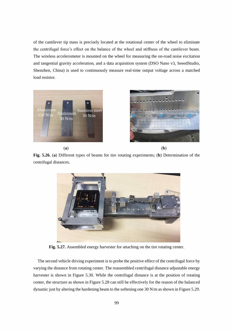
99
of the cantilever tip mass is precisely located at the rotational center of the wheel to eliminate
the centrifugal force’s effect on the balance of the wheel and stiffness of the cantilever beam.
The wireless accelerometer is mounted on the wheel for measuring the on-road noise excitation
and tangential gravity acceleration, and a data acquisition system (DSO Nano v3, SeeedStudio,
Shenzhen, China) is used to continuously measure real-time output voltage across a matched
load resistor.
(a) (b)
Fig. 5.26. (a) Different types of beams for tire rotating experiments; (b) Determination of the
centrifugal distances.
Fig. 5.27. Assembled energy harvester for attaching on the tire rotating center.
The second vehicle driving experiment is to probe the positive effect of the centrifugal force by
varying the distance from rotating center. The reassembled centrifugal distance adjustable energy
harvester is shown in Figure 5.30. While the centrifugal distance is at the position of rotating
center, the structure as shown in Figure 5.28 can still be effectively for the reason of the balanced
dynamic just by altering the hardening beam to the softening one 30 N/m as shown in Figure 5.29.
Aluminum
150 N/m Aluminum
30 N/m
Stainless steel
30 N/m
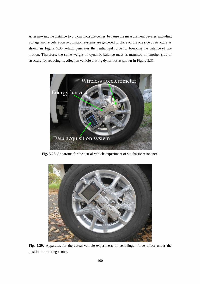
100
After moving the distance to 3.6 cm from tire center, because the measurement devices including
voltage and acceleration acquisition systems are gathered to place on the one side of structure as
shown in Figure 5.30, which generates the centrifugal force for breaking the balance of tire
motion. Therefore, the same weight of dynamic balance mass is mounted on another side of
structure for reducing its effect on vehicle driving dynamics as shown in Figure 5.31.
Fig. 5.28. Apparatus for the actual-vehicle experiment of stochastic resonance.
Fig. 5.29. Apparatus for the actual-vehicle experiment of centrifugal force effect under the
position of rotating center.
Wireless accelerometer
Data acquisition system
Energy harvester
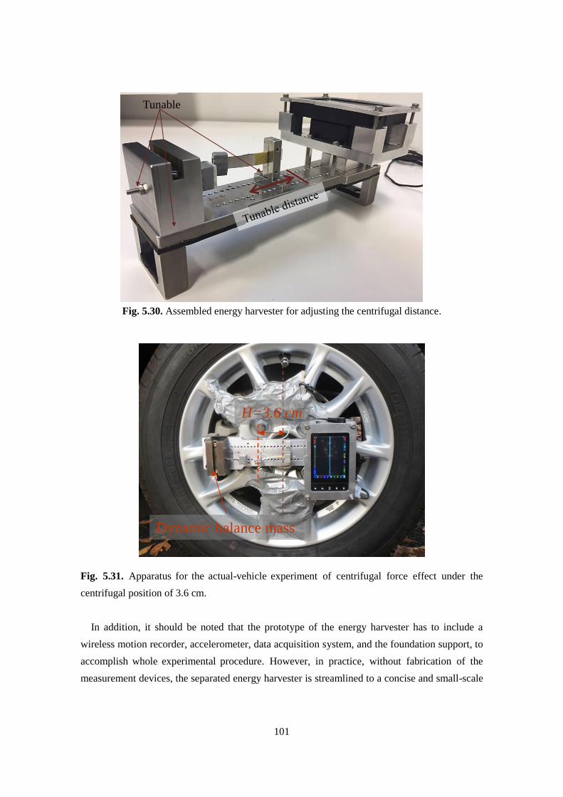
101
Fig. 5.30. Assembled energy harvester for adjusting the centrifugal distance.
Fig. 5.31. Apparatus for the actual-vehicle experiment of centrifugal force effect under the
centrifugal position of 3.6 cm.
In addition, it should be noted that the prototype of the energy harvester has to include a
wireless motion recorder, accelerometer, data acquisition system, and the foundation support, to
accomplish whole experimental procedure. However, in practice, without fabrication of the
measurement devices, the separated energy harvester is streamlined to a concise and small-scale
Tunable
H=3.6 cm
Dynamic balance mass
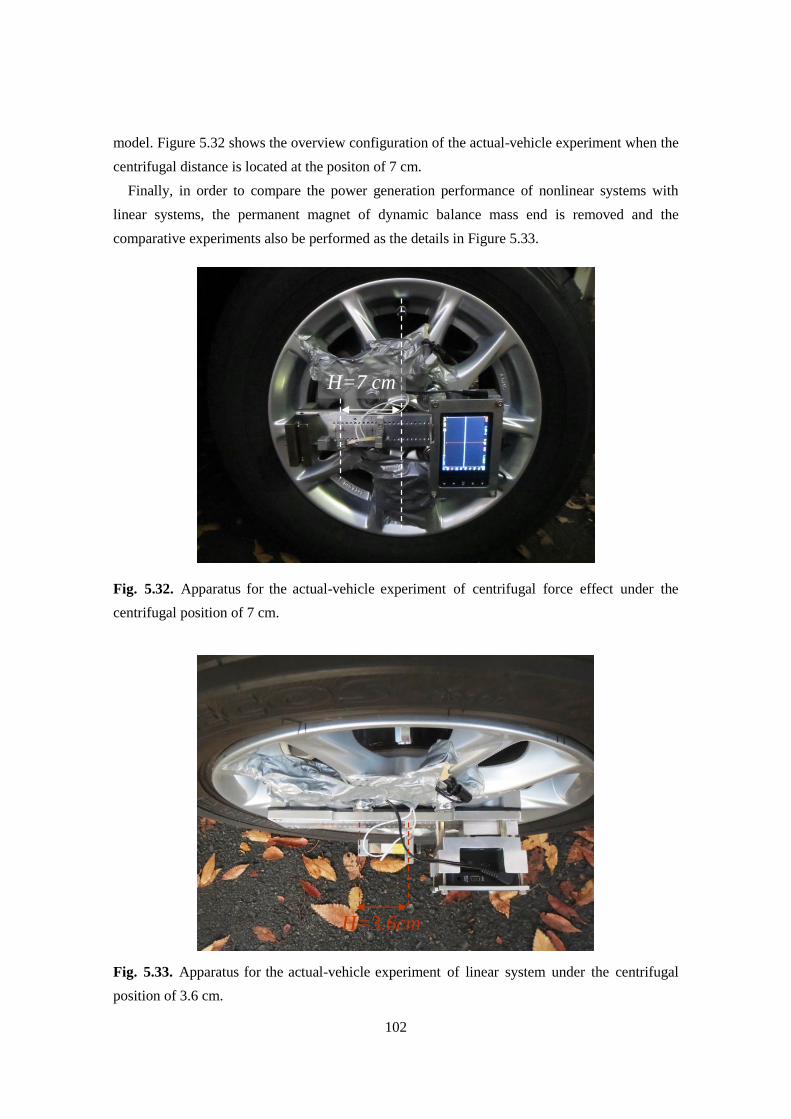
102
model. Figure 5.32 shows the overview configuration of the actual-vehicle experiment when the
centrifugal distance is located at the positon of 7 cm.
Finally, in order to compare the power generation performance of nonlinear systems with
linear systems, the permanent magnet of dynamic balance mass end is removed and the
comparative experiments also be performed as the details in Figure 5.33.
Fig. 5.32. Apparatus for the actual-vehicle experiment of centrifugal force effect under the
centrifugal position of 7 cm.
Fig. 5.33. Apparatus for the actual-vehicle experiment of linear system under the centrifugal
position of 3.6 cm.
H=7 cm
H=3.6cm
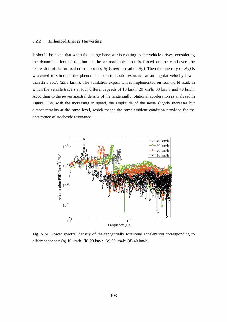
103
5.2.2 Enhanced Energy Harvesting
It should be noted that when the energy harvester is rotating as the vehicle drives, considering
the dynamic effect of rotation on the on-road noise that is forced on the cantilever, the
expression of the on-road noise becomes N(t)sinωt instead of N(t). Then the intensity of N(t) is
weakened to stimulate the phenomenon of stochastic resonance at an angular velocity lower
than 22.5 rad/s (23.5 km/h). The validation experiment is implemented on real-world road, in
which the vehicle travels at four different speeds of 10 km/h, 20 km/h, 30 km/h, and 40 km/h.
According to the power spectral density of the tangentially rotational acceleration as analyzed in
Figure 5.34, with the increasing in speed, the amplitude of the noise slightly increases but
almost remains at the same level, which means the same ambient condition provided for the
occurrence of stochastic resonance.
Fig. 5.34. Power spectral density of the tangentially rotational acceleration corresponding to
different speeds: (a) 10 km/h; (b) 20 km/h; (c) 30 km/h; (d) 40 km/h.
100
101
10-4
10-2
100
102
Frequency (Hz)
Acc
eler
atio
n P
SD
((m
/s2)2
/Hz)
40 km/h
30 km/h
20 km/h
10 km/h
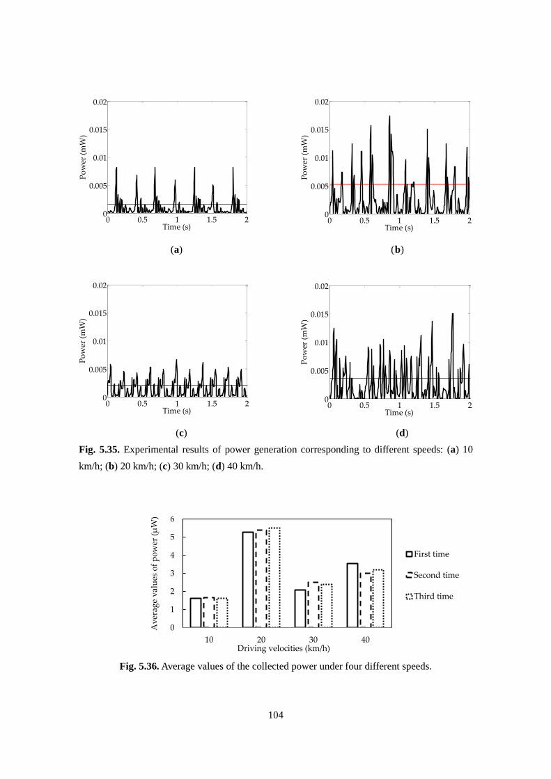
104
(a) (b)
(c) (d)
Fig. 5.35. Experimental results of power generation corresponding to different speeds: (a) 10
km/h; (b) 20 km/h; (c) 30 km/h; (d) 40 km/h.
Fig. 5.36. Average values of the collected power under four different speeds.
0 0.5 1 1.5 20
0.005
0.01
0.015
0.02
Time (s)
Po
wer
(m
W)
0 0.5 1 1.5 20
0.005
0.01
0.015
0.02
Time (s)
Po
wer
(m
W)
0
1
2
3
4
5
6
10 20 30 40
First time
Second time
Third time
0 0.5 1 1.5 20
0.005
0.01
0.015
0.02
Time (s)
Po
wer
(m
W)
Av
erag
e v
alu
es o
f p
ow
er (
μW
)
Driving velocities (km/h)
0 0.5 1 1.5 20
0.005
0.01
0.015
0.02
Time (s)
Po
wer
(m
W)
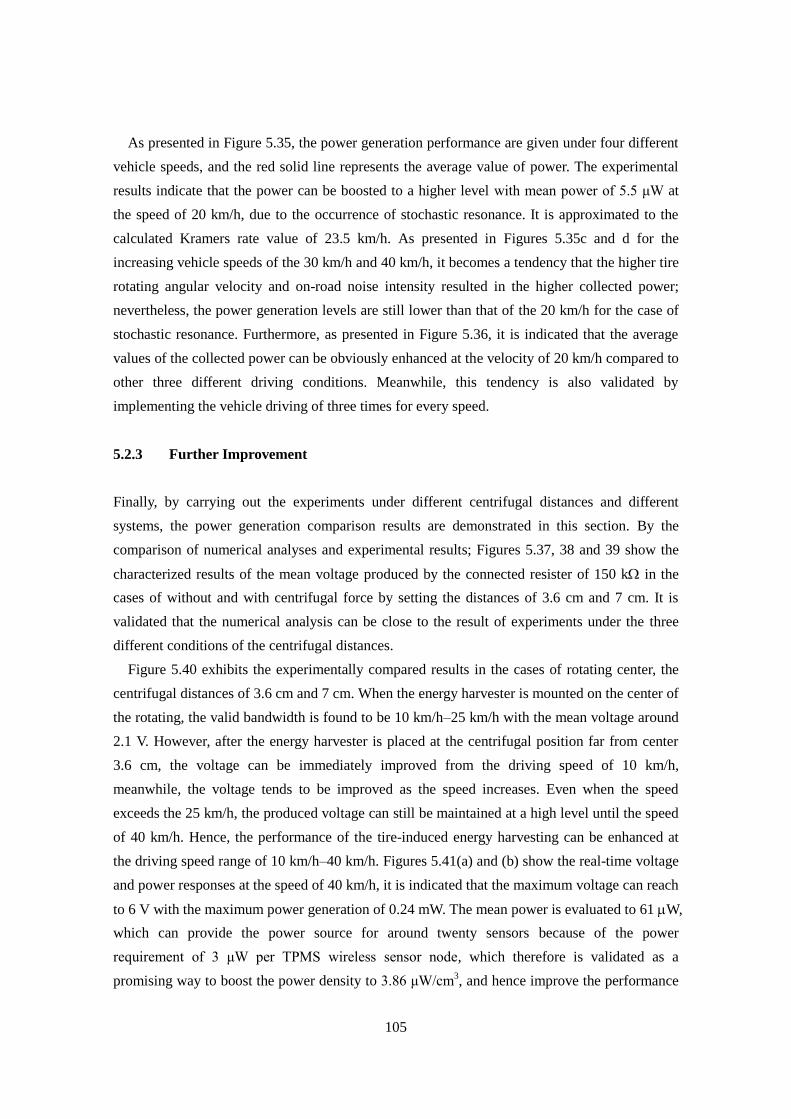
105
As presented in Figure 5.35, the power generation performance are given under four different
vehicle speeds, and the red solid line represents the average value of power. The experimental
results indicate that the power can be boosted to a higher level with mean power of 5.5 μW at
the speed of 20 km/h, due to the occurrence of stochastic resonance. It is approximated to the
calculated Kramers rate value of 23.5 km/h. As presented in Figures 5.35c and d for the
increasing vehicle speeds of the 30 km/h and 40 km/h, it becomes a tendency that the higher tire
rotating angular velocity and on-road noise intensity resulted in the higher collected power;
nevertheless, the power generation levels are still lower than that of the 20 km/h for the case of
stochastic resonance. Furthermore, as presented in Figure 5.36, it is indicated that the average
values of the collected power can be obviously enhanced at the velocity of 20 km/h compared to
other three different driving conditions. Meanwhile, this tendency is also validated by
implementing the vehicle driving of three times for every speed.
5.2.3 Further Improvement
Finally, by carrying out the experiments under different centrifugal distances and different
systems, the power generation comparison results are demonstrated in this section. By the
comparison of numerical analyses and experimental results; Figures 5.37, 38 and 39 show the
characterized results of the mean voltage produced by the connected resister of 150 k in the
cases of without and with centrifugal force by setting the distances of 3.6 cm and 7 cm. It is
validated that the numerical analysis can be close to the result of experiments under the three
different conditions of the centrifugal distances.
Figure 5.40 exhibits the experimentally compared results in the cases of rotating center, the
centrifugal distances of 3.6 cm and 7 cm. When the energy harvester is mounted on the center of
the rotating, the valid bandwidth is found to be 10 km/h–25 km/h with the mean voltage around
2.1 V. However, after the energy harvester is placed at the centrifugal position far from center
3.6 cm, the voltage can be immediately improved from the driving speed of 10 km/h,
meanwhile, the voltage tends to be improved as the speed increases. Even when the speed
exceeds the 25 km/h, the produced voltage can still be maintained at a high level until the speed
of 40 km/h. Hence, the performance of the tire-induced energy harvesting can be enhanced at
the driving speed range of 10 km/h–40 km/h. Figures 5.41(a) and (b) show the real-time voltage
and power responses at the speed of 40 km/h, it is indicated that the maximum voltage can reach
to 6 V with the maximum power generation of 0.24 mW. The mean power is evaluated to 61 W,
which can provide the power source for around twenty sensors because of the power
requirement of 3 μW per TPMS wireless sensor node, which therefore is validated as a
promising way to boost the power density to 3.86 μW/cm3, and hence improve the performance
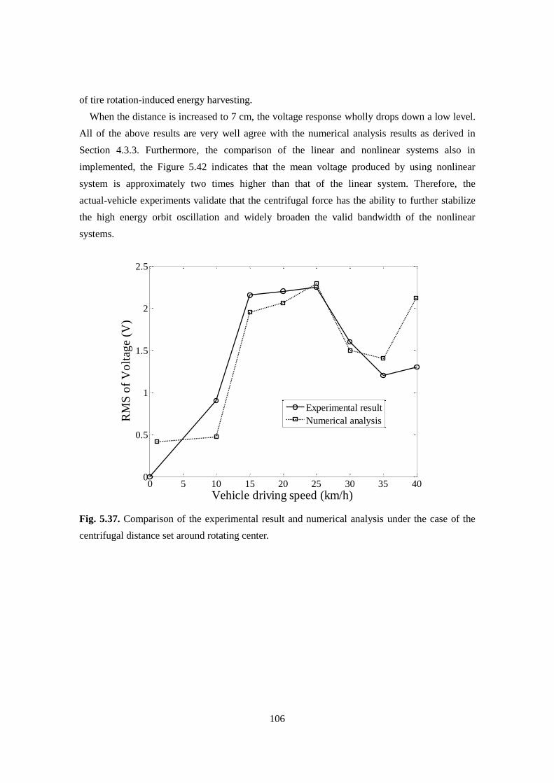
106
of tire rotation-induced energy harvesting.
When the distance is increased to 7 cm, the voltage response wholly drops down a low level.
All of the above results are very well agree with the numerical analysis results as derived in
Section 4.3.3. Furthermore, the comparison of the linear and nonlinear systems also in
implemented, the Figure 5.42 indicates that the mean voltage produced by using nonlinear
system is approximately two times higher than that of the linear system. Therefore, the
actual-vehicle experiments validate that the centrifugal force has the ability to further stabilize
the high energy orbit oscillation and widely broaden the valid bandwidth of the nonlinear
systems.
Fig. 5.37. Comparison of the experimental result and numerical analysis under the case of the
centrifugal distance set around rotating center.
0 5 10 15 20 25 30 35 400
0.5
1
1.5
2
2.5
Vehicle driving speed (km/h)
RM
S o
f V
olt
age
(V)
Experimental result
Numerical analysis
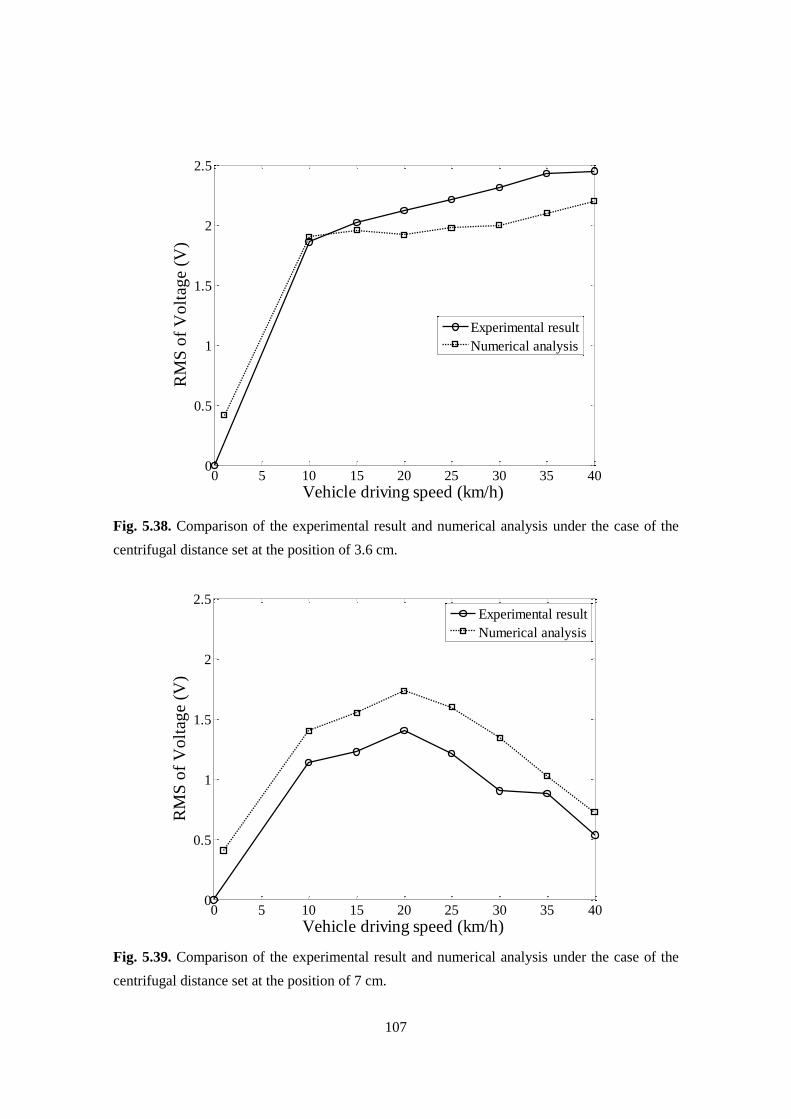
107
Fig. 5.38. Comparison of the experimental result and numerical analysis under the case of the
centrifugal distance set at the position of 3.6 cm.
Fig. 5.39. Comparison of the experimental result and numerical analysis under the case of the
centrifugal distance set at the position of 7 cm.
0 5 10 15 20 25 30 35 400
0.5
1
1.5
2
2.5
Vehicle driving speed (km/h)
RM
S o
f V
olt
age
(V)
Experimental result
Numerical analysis
0 5 10 15 20 25 30 35 400
0.5
1
1.5
2
2.5
Vehicle driving speed (km/h)
RM
S o
f V
olt
age
(V)
Experimental result
Numerical analysis
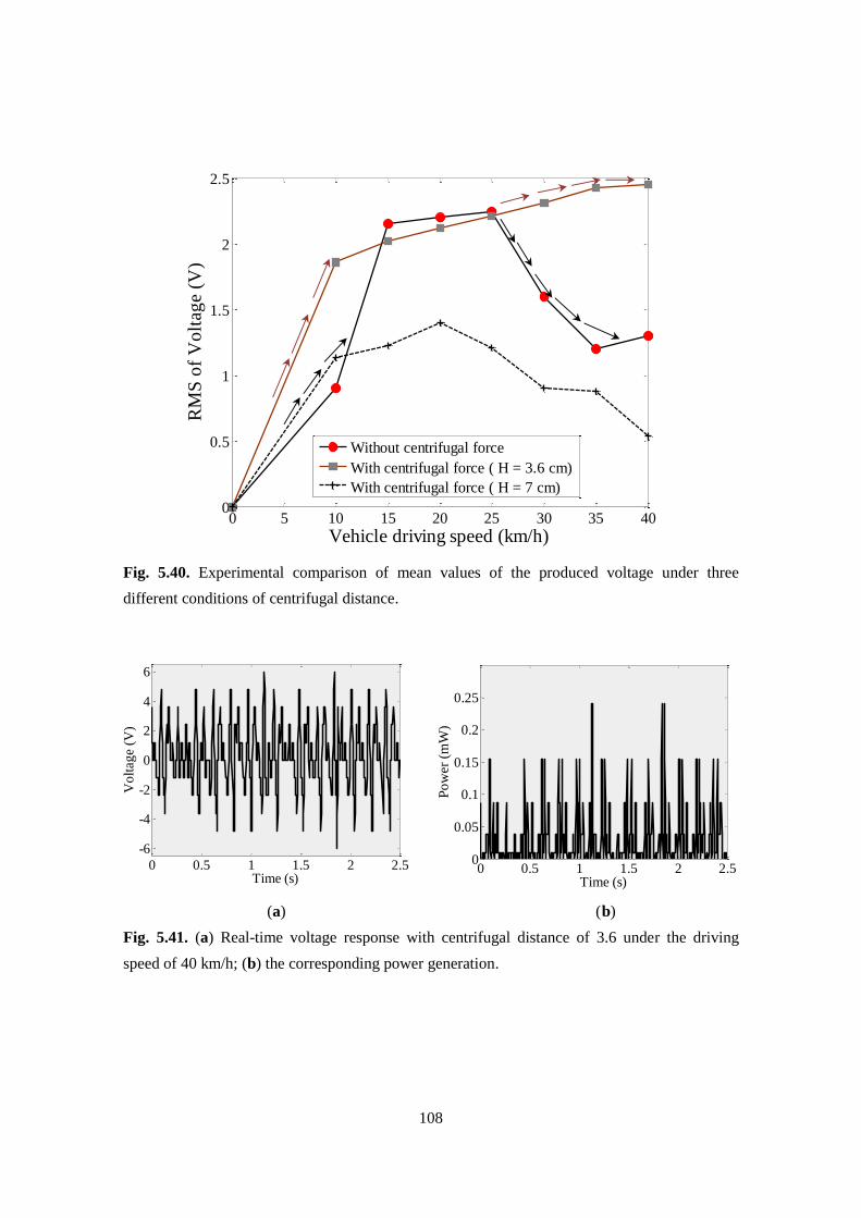
108
Fig. 5.40. Experimental comparison of mean values of the produced voltage under three
different conditions of centrifugal distance.
(a) (b)
Fig. 5.41. (a) Real-time voltage response with centrifugal distance of 3.6 under the driving
speed of 40 km/h; (b) the corresponding power generation.
0 5 10 15 20 25 30 35 400
0.5
1
1.5
2
2.5
Vehicle driving speed (km/h)
RM
S o
f V
olt
age
(V)
Without centrifugal force
With centrifugal force ( H = 3.6 cm)
With centrifugal force ( H = 7 cm)
0 0.5 1 1.5 2 2.5
-6
-4
-2
0
2
4
6
Time (s)
Vo
ltag
e (V
)
0 0.5 1 1.5 2 2.50
0.05
0.1
0.15
0.2
0.25
Time (s)
Po
wer
(m
W)
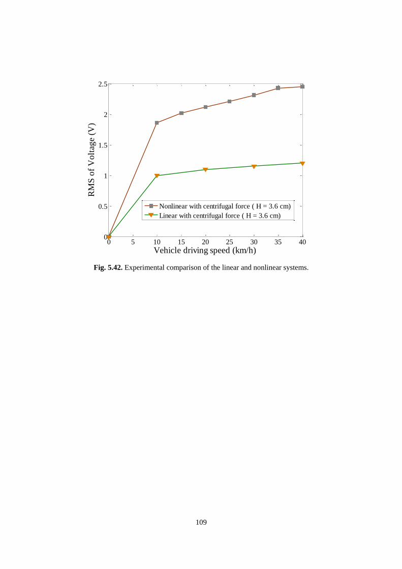
109
Fig. 5.42. Experimental comparison of the linear and nonlinear systems.
0 5 10 15 20 25 30 35 400
0.5
1
1.5
2
2.5
Vehicle driving speed (km/h)
RM
S o
f V
olt
age
(V)
Nonlinear with centrifugal force ( H = 3.6 cm)
Linear with centrifugal force ( H = 3.6 cm)

110
Chapter 6
Discussions
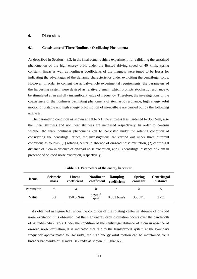
111
6. Discussions
6.1 Coexistence of Three Nonlinear Oscillating Phenomena
As described in Section 4.3.3, in the final actual-vehicle experiment, for validating the sustained
phenomenon of the high energy orbit under the limited driving speed of 40 km/h, spring
constant, linear as well as nonlinear coefficients of the magnets were tuned to be lesser for
indicating the advantages of the dynamic characteristics under exploiting the centrifugal force.
However, in order to content the actual-vehicle experimental requirements, the parameters of
the harvesting system were devised as relatively small, which prompts stochastic resonance to
be stimulated at an awfully insignificant value of frequency. Therefore, the investigations of the
coexistence of the nonlinear oscillating phenomena of stochastic resonance, high energy orbit
motion of bistable and high energy orbit motion of monostbale are carried out by the following
analyses.
The parametric condition as shown at Table 6.1, the stiffness k is hardened to 350 N/m, also
the linear stiffness and nonlinear stiffness are increased respectively. In order to confirm
whether the three nonlinear phenomena can be coexisted under the rotating condition of
considering the centrifugal effect, the investigations are carried out under three different
conditions as follows: (1) rotating center in absence of on-road noise excitation, (2) centrifugal
distance of 2 cm in absence of on-road noise excitation, and (3) centrifugal distance of 2 cm in
presence of on-road noise excitation, respectively.
Table 6.1. Parameters of the energy harvester.
Items Seismeic
mass
Linear
coefficient
Nonlinear
coefficient
Damping
coefficient
Spring
constant
Centrifugal
distance
Parameter m a b c k H
Value 8 g 150.5 N/m 5.2×10
7
N/m3
0.081 N/m/s 350 N/m 2 cm
As obtained in Figure 6.1, under the condition of the rotating center in absence of on-road
noise excitation, it is observed that the high energy orbit oscillation occurs over the bandwidth
of 78 rad/s–244.7 rad/s. Under the condition of the centrifugal distance of 2 cm in absence of
on-road noise excitation, it is indicated that due to the transformed system at the boundary
frequency approximated to 162 rad/s, the high energy orbit motion can be maintained for a
broader bandwidth of 50 rad/s–317 rad/s as shown in Figure 6.2.
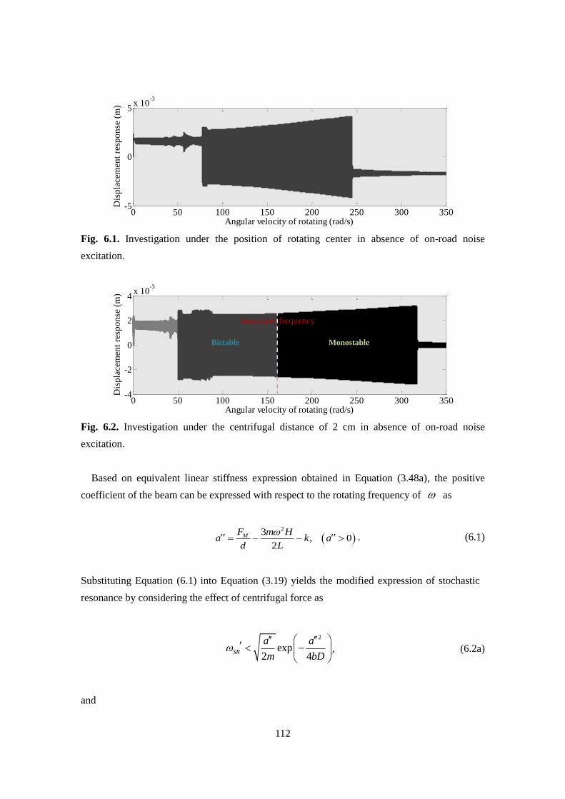
112
Fig. 6.1. Investigation under the position of rotating center in absence of on-road noise
excitation.
Fig. 6.2. Investigation under the centrifugal distance of 2 cm in absence of on-road noise
excitation.
Based on equivalent linear stiffness expression obtained in Equation (3.48a), the positive
coefficient of the beam can be expressed with respect to the rotating frequency of as
23
, 02
MF m Ha k a
d L
. (6.1)
Substituting Equation (6.1) into Equation (3.19) yields the modified expression of stochastic
resonance by considering the effect of centrifugal force as
2
exp2 4
SR
a a
m bD
, (6.2a)
and
0 50 100 150 200 250 300 350-5
0
5x 10
-3
Angular velocity of rotating (rad/s)
Dis
pla
cem
ent
resp
on
se (
m)
0 50 100 150 200 250 300 350-4
-2
0
2
4x 10
-3
Angular velocity of rotating (rad/s)
Dis
pla
cem
ent
resp
on
se (
m)
Bistable Monostable
Boundary frequency
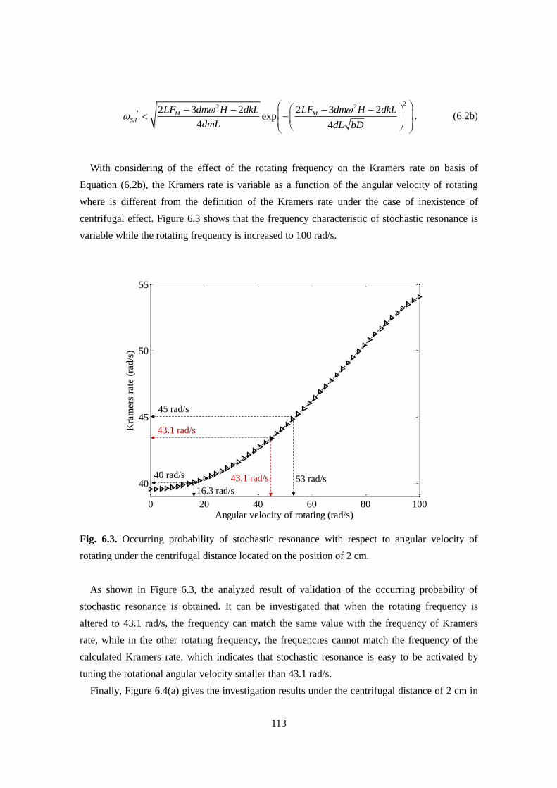
113
22 22 3 2 2 3 2
exp4 4
M MSR
LF dm H dkL LF dm H dkL
dmL dL bD
. (6.2b)
With considering of the effect of the rotating frequency on the Kramers rate on basis of
Equation (6.2b), the Kramers rate is variable as a function of the angular velocity of rotating
where is different from the definition of the Kramers rate under the case of inexistence of
centrifugal effect. Figure 6.3 shows that the frequency characteristic of stochastic resonance is
variable while the rotating frequency is increased to 100 rad/s.
Fig. 6.3. Occurring probability of stochastic resonance with respect to angular velocity of
rotating under the centrifugal distance located on the position of 2 cm.
As shown in Figure 6.3, the analyzed result of validation of the occurring probability of
stochastic resonance is obtained. It can be investigated that when the rotating frequency is
altered to 43.1 rad/s, the frequency can match the same value with the frequency of Kramers
rate, while in the other rotating frequency, the frequencies cannot match the frequency of the
calculated Kramers rate, which indicates that stochastic resonance is easy to be activated by
tuning the rotational angular velocity smaller than 43.1 rad/s.
Finally, Figure 6.4(a) gives the investigation results under the centrifugal distance of 2 cm in
0 20 40 60 80 100
40
45
50
55
Angular velocity of rotating (rad/s)
Kra
mer
s ra
te (
rad/s
)
45 rad/s
53 rad/s
43.1 rad/s
43.1 rad/s40 rad/s
16.3 rad/s
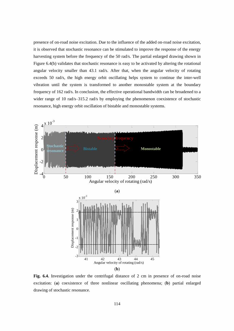
114
presence of on-road noise excitation. Due to the influence of the added on-road noise excitation,
it is observed that stochastic resonance can be stimulated to improve the response of the energy
harvesting system before the frequency of the 50 rad/s. The partial enlarged drawing shown in
Figure 6.4(b) validates that stochastic resonance is easy to be activated by altering the rotational
angular velocity smaller than 43.1 rad/s. After that, when the angular velocity of rotating
exceeds 50 rad/s, the high energy orbit oscillating helps system to continue the inter-well
vibration until the system is transformed to another monostable system at the boundary
frequency of 162 rad/s. In conclusion, the effective operational bandwidth can be broadened to a
wider range of 10 rad/s–315.2 rad/s by employing the phenomenon coexistence of stochastic
resonance, high energy orbit oscillation of bistable and monostable systems.
(a)
(b)
Fig. 6.4. Investigation under the centrifugal distance of 2 cm in presence of on-road noise
excitation: (a) coexistence of three nonlinear oscillating phenomena; (b) partial enlarged
drawing of stochastic resonance.
0 50 100 150 200 250 300 350-4
-2
0
2
4x 10
-3
Angular velocity of rotating (rad/s)
Dis
pla
cem
ent
resp
on
se (
m)
Stochastic
resonanceBistable Monostable
Boundary frequency
41 42 43 44 45-3
-2
-1
0
1
2
3x 10
-3
Angular velocity of rotating (rad/s)
Dis
pla
cem
ent
resp
on
se (
m)
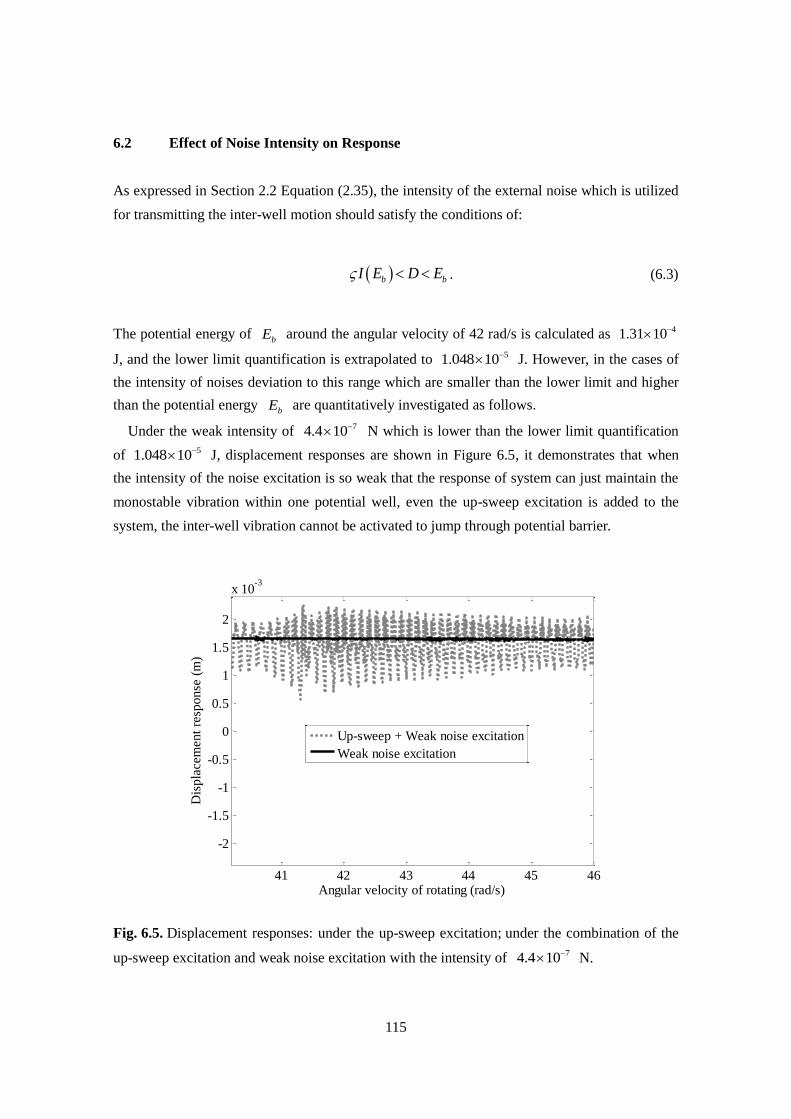
115
6.2 Effect of Noise Intensity on Response
As expressed in Section 2.2 Equation (2.35), the intensity of the external noise which is utilized
for transmitting the inter-well motion should satisfy the conditions of:
b bI E D E . (6.3)
The potential energy of bE around the angular velocity of 42 rad/s is calculated as 41.31 10
J, and the lower limit quantification is extrapolated to 51.048 10 J. However, in the cases of
the intensity of noises deviation to this range which are smaller than the lower limit and higher
than the potential energy bE are quantitatively investigated as follows.
Under the weak intensity of 74.4 10 N which is lower than the lower limit quantification
of 51.048 10 J, displacement responses are shown in Figure 6.5, it demonstrates that when
the intensity of the noise excitation is so weak that the response of system can just maintain the
monostable vibration within one potential well, even the up-sweep excitation is added to the
system, the inter-well vibration cannot be activated to jump through potential barrier.
Fig. 6.5. Displacement responses: under the up-sweep excitation; under the combination of the
up-sweep excitation and weak noise excitation with the intensity of 74.4 10 N.
41 42 43 44 45 46
-2
-1.5
-1
-0.5
0
0.5
1
1.5
2
x 10-3
Angular velocity of rotating (rad/s)
Dis
pla
cem
ent
resp
onse
(m
)
Up-sweep + Weak noise excitation
Weak noise excitation
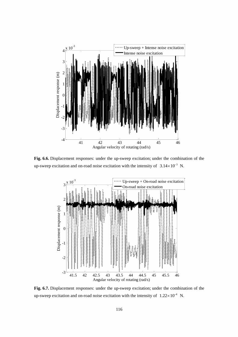
116
Fig. 6.6. Displacement responses: under the up-sweep excitation; under the combination of the
up-sweep excitation and on-road noise excitation with the intensity of 33.14 10 N.
Fig. 6.7. Displacement responses: under the up-sweep excitation; under the combination of the
up-sweep excitation and on-road noise excitation with the intensity of 41.22 10 N.
41 42 43 44 45 46-4
-3
-2
-1
0
1
2
3
4x 10
-3
Angular velocity of rotating (rad/s)
Dis
pla
cem
ent
resp
on
se (
m)
Up-sweep + Intense noise excitation
Intense noise excitation
41.5 42 42.5 43 43.5 44 44.5 45 45.5 46-3
-2
-1
0
1
2
3x 10
-3
Angular velocity of rotating (rad/s)
Dis
pla
cem
ent
resp
onse
(m
)
Up-sweep + On-road noise excitation
On-road noise excitation
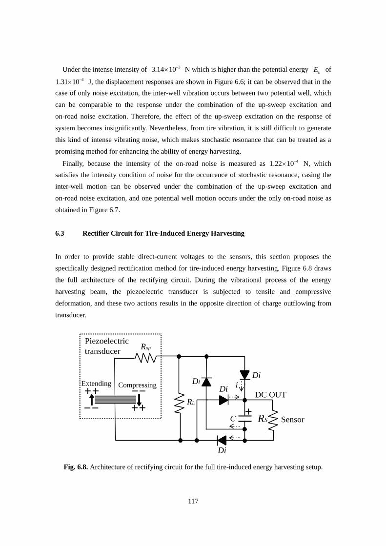
117
Under the intense intensity of 33.14 10 N which is higher than the potential energy bE of
41.31 10 J, the displacement responses are shown in Figure 6.6; it can be observed that in the
case of only noise excitation, the inter-well vibration occurs between two potential well, which
can be comparable to the response under the combination of the up-sweep excitation and
on-road noise excitation. Therefore, the effect of the up-sweep excitation on the response of
system becomes insignificantly. Nevertheless, from tire vibration, it is still difficult to generate
this kind of intense vibrating noise, which makes stochastic resonance that can be treated as a
promising method for enhancing the ability of energy harvesting.
Finally, because the intensity of the on-road noise is measured as 41.22 10 N, which
satisfies the intensity condition of noise for the occurrence of stochastic resonance, casing the
inter-well motion can be observed under the combination of the up-sweep excitation and
on-road noise excitation, and one potential well motion occurs under the only on-road noise as
obtained in Figure 6.7.
6.3 Rectifier Circuit for Tire-Induced Energy Harvesting
In order to provide stable direct-current voltages to the sensors, this section proposes the
specifically designed rectification method for tire-induced energy harvesting. Figure 6.8 draws
the full architecture of the rectifying circuit. During the vibrational process of the energy
harvesting beam, the piezoelectric transducer is subjected to tensile and compressive
deformation, and these two actions results in the opposite direction of charge outflowing from
transducer.
Fig. 6.8. Architecture of rectifying circuit for the full tire-induced energy harvesting setup.
Di
Di
DiDi
C
Rop
DC OUTRL
Extending Compressing
Piezoelectric
transducer
SensorRS
i
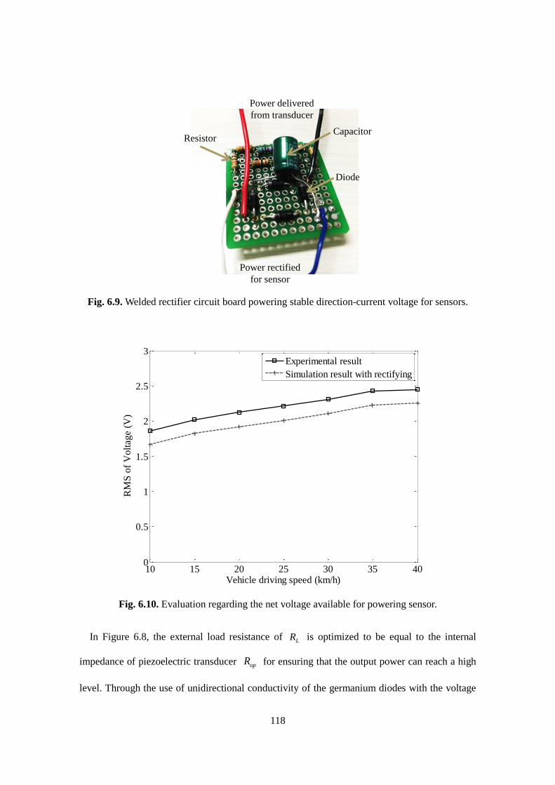
118
Fig. 6.9. Welded rectifier circuit board powering stable direction-current voltage for sensors.
Fig. 6.10. Evaluation regarding the net voltage available for powering sensor.
In Figure 6.8, the external load resistance of LR is optimized to be equal to the internal
impedance of piezoelectric transducer opR for ensuring that the output power can reach a high
level. Through the use of unidirectional conductivity of the germanium diodes with the voltage
Power delivered
from transducer
Power rectified
for sensor
Diode
CapacitorResistor
10 15 20 25 30 35 400
0.5
1
1.5
2
2.5
3
Vehicle driving speed (km/h)
RM
S o
f V
olt
age
(V)
Experimental result
Simulation result with rectifying
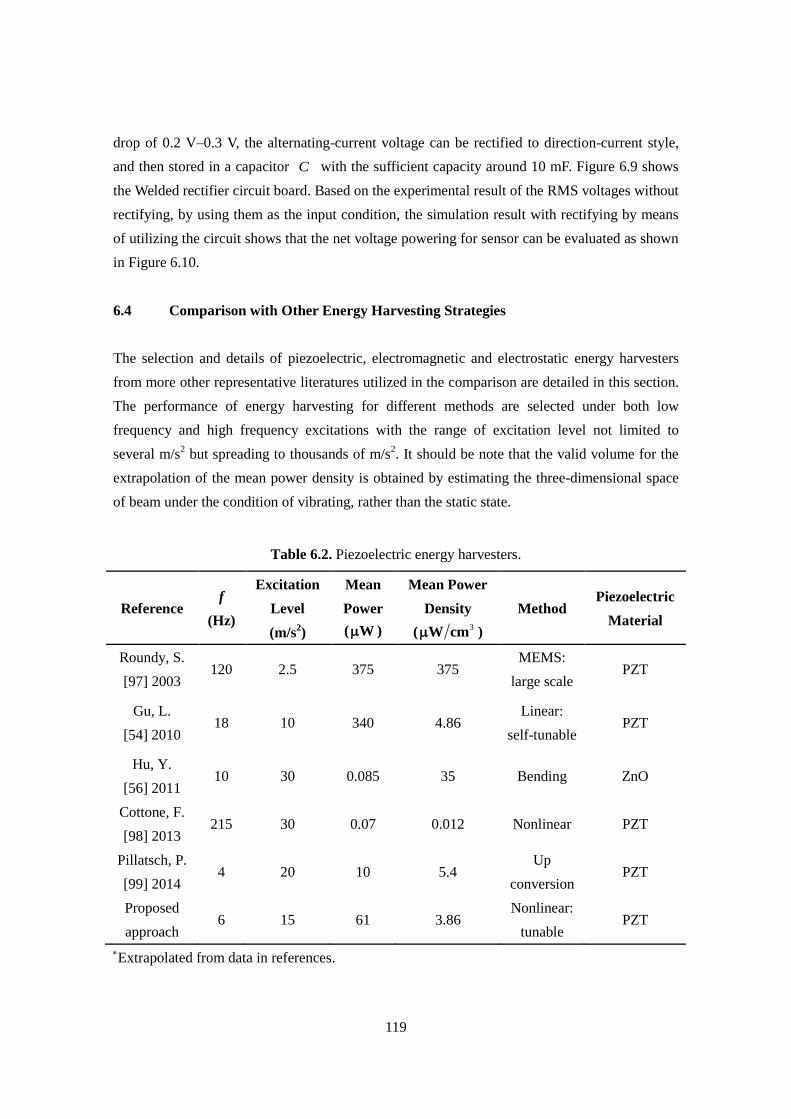
119
drop of 0.2 V–0.3 V, the alternating-current voltage can be rectified to direction-current style,
and then stored in a capacitor C with the sufficient capacity around 10 mF. Figure 6.9 shows
the Welded rectifier circuit board. Based on the experimental result of the RMS voltages without
rectifying, by using them as the input condition, the simulation result with rectifying by means
of utilizing the circuit shows that the net voltage powering for sensor can be evaluated as shown
in Figure 6.10.
6.4 Comparison with Other Energy Harvesting Strategies
The selection and details of piezoelectric, electromagnetic and electrostatic energy harvesters
from more other representative literatures utilized in the comparison are detailed in this section.
The performance of energy harvesting for different methods are selected under both low
frequency and high frequency excitations with the range of excitation level not limited to
several m/s2 but spreading to thousands of m/s
2. It should be note that the valid volume for the
extrapolation of the mean power density is obtained by estimating the three-dimensional space
of beam under the condition of vibrating, rather than the static state.
Table 6.2. Piezoelectric energy harvesters.
Reference f
(Hz)
Excitation
Level
(m/s2)
Mean
Power
( W )
Mean Power
Density
(3
W cm )
Method Piezoelectric
Material
Roundy, S.
[97] 2003 120 2.5 375 375
MEMS:
large scale PZT
Gu, L.
[54] 2010 18 10 340 4.86
Linear:
self-tunable PZT
Hu, Y.
[56] 2011 10 30 0.085 35 Bending ZnO
Cottone, F.
[98] 2013 215 30 0.07 0.012 Nonlinear PZT
Pillatsch, P.
[99] 2014 4 20 10 5.4
Up
conversion PZT
Proposed
approach 6 15 61 3.86
Nonlinear:
tunable PZT
Extrapolated from data in references.
120
Table 6.3. Electromagnetic energy harvesters.
Reference f
(Hz)
Excitation
Level
(m/s2)
Mean
Power
( W )
Mean Power
Density
(3
W cm )
Method Structure
Material
Koukharenko, E.
[100] 2006 1615 3.92 0.104 1.04 Resonance Silicon
Kulah, H.
[101] 2008 25 N/A 3.97 1.99
Up
conversion Styrene
Wang, Y. J.
[67] 2015 6 10 30 0.94 Nonlinear Copper
N/A: Not Available
Table 6.4. Electrostatic energy harvesters and other approach.
Reference f
(Hz)
Excitation
Level
(m/s2)
Mean
Power
( W )
Mean Power
Density
(3
W cm )
Method Type
Arakawa, Y.
[102] 2004 10 3.9 6 7.5 Electret IPO
Lo, H.
[103] 2008 50 576.6 17.98 0.36 Electret OP
Manla, G.
[104] 2012 5.55 119 3.5 0.14
Nonlinear:
impact Hybrid
IPO: In-Plane Overlap OP: Out-of-plane
Tables 6.2, 6.3, 6.4 demonstrate the previous works trialing to improve the harvested power
utilizing different approaches. By comparison of the each table, the compact miniaturization of
MEMS devices, although they have high power densities, the produced powers are still
relatively low using the electret IPO type energy harvester; nevertheless, the technique of
enlarging scale of MEMS device can be considered as an effective approach to improve the
output power.
The method using self-tunable linear structure demonstrates a relatively high capacity of
energy harvesting compared to the method of taking advantage of resonance, but it is difficult to
adjust the frequency of natural resonance to match the varying frequency of the external
excitation in practice. By using this proposed approach, it is no need to match the resonance of
system as long as its operational frequency bandwidth is broadened to include the frequency

121
range of the external excitation.
Another approach of attaching the separate piezoelectric material inner tire trends to increase
the power density, due to the internal attachment position of tire, it becomes inconvenient to
replace the harvesting system, in other words, the replacement cost is expensive. Using this
proposed approach, because the harvester is attached on the surface of tire wheel, which makes
the process of replacement to be uncomplicated.
Frequency-up conversion can activate the response of vibrating around extremely high
frequency to improve the power density, which although is comparable to the power density
obtained in this research. Due to high-frequency vibration, the inevitable of increasing the
stiffness of system to a large elasticity coefficient makes the output response not so high
compared to the result of this proposed approach.
For the other mechanical strategies of utilizing nonlinear as well as nonlinear combined with
impact effect, they can be treated as the potential methods to harvest the power by the simplex
nonlinear vibration. However, in this research exploiting the featured approach of the tunable
nonlinear characteristics to activate the coexisting of multiple nonlinear vibrations can further
broaden the effective bandwidth for making efforts to improve the capacity of energy
harvesting.

122
Chapter 7
Conclusions
123
7. Conclusions
Energy harvesting from ambient vibration has attracted the interest of many researchers in the
last decade. Contributing to the hot topic, this thesis focused on utilizing the nonlinear
phenomena covering stochastic resonance, high energy orbit oscillation of bistable systems, and
high energy orbit of monostbale systems for rotation-induced vibrational energy harvester. It is
worth highlighting that the operational bandwidth of rotational frequency can be significantly
broadened by the combinations of stochastic resonance and high energy orbit characteristic, as
well as the high energy orbit characteristics of bistable and monostable oscillator.
The detailed conclusions of each chapter are drawn, as follows:
In Chapter 2, the dynamics and its characteristics are introduced for the monostable and
bistable Duffing oscillators under harmonic excitations, and stochastic resonance under the
on-road noise excitation combined with gravitational effects. In the monostable case, from the
frequency-amplitude response, it was demonstrated that the dynamic response can be improved
at a wide frequency bandwidth of excitation, and the operational bandwidth can be further
improved for energy harvesting by increasing the linear and nonlinear stiffness to stabilizing the
high energy orbit motion. Another method to broaden the bandwidth is to use high energy orbit
motion of bistsble. Moreover, the specific theory was also introduced for derivation process of
stochastic resonance. Finally, the existing challenges were described regarding how to exploit
nonlinear systems to the actual vehicle tires, which can result in excellent energy harvesting
performance.
In Chapter 3, the methodologies were presented to exploit tire-rotating harvester, and a
bistable energy harvester was proposed to collect energy from tire rotational environments.
With the theoretical investigation, the bistable energy harvester is suitable for enhance
performance of energy harvesting by application of stochastic resonance. Under the
environments of tire rotation, the periodical force is autonomously self-excited by the
gravitational effect of the magnetic end mass, and the noise excitation generated from the road
provide the necessary conditions for the occurrence of stochastic resonance. In this work, it has
been validated that there is no necessary to prepare an efficiency-reducing additional periodic
modulation force, as it is now provided by the rotation of the car wheel. Therefore, the potential
for the implementation of stochastic resonance is practically realizable in this particular system.
The modelling analyses of energy harvester were processed under the noise and gravitational
effect of tire rotations from an ideally simulating setting, as well as the real-world on-road
environment, respectively. Furthermore, the bandwidth can be further broadened on the basis of
combining two phenomena of stochastic resonance and high energy orbit oscillation. In addition,
the centrifugally rotating dynamics was investigated to assess the influence of centrifugal force
124
on the rotational nonlinear energy harvester, and it was indicated that the centrifugal force might
be applied as another active effectiveness to improve the harvesting performance.
In Chapter 4, by implementing the numerical simulations, it indicated that the phenomenon of
stochastic resonance can occur when the tire rotates around the angular velocity of 98 rad/s
under the simulated road noise excitation over a bandwidth of 0 Hz–1 kHz. The present study
applied the periodic gravity force and on-road noise excitation of the rotating wheel, to validate
the effectiveness of energy harvesting by the application of the phenomenon of stochastic
resonance. The systematic structure was modeled under the real condition of on-road noise
excitation, when a vehicle travels on a smooth paved road. Therefore, the effective frequency
bandwidth of the energy harvester can be extended to a wider range by utilizing stochastic
resonance combined with high energy orbit oscillating. In the last section, a simulation study
was investigated to verify that the performance characteristic under the condition of exploiting
the centrifugal force. In this case, the hardening and softening stiffness coefficients are tunable
along with the change of rotational frequency for increasing the stiffness, in which the
harvesting system can automatically transform the initial bistable into monostable oscillations,
for stabilizing the high energy orbit. It was approved that the proposed method can achieve a
significantly broadening bandwidth for the vibrational energy harvesting.
In Chapter 5, a series of experimental studies was carried out to validate proposed method, by
the development of energy harvesting prototypes. According to the laboratory experiment,
under the simulating conditions, the maximum instantaneous power was achieved to 0.14 mW
under high angular velocity of 98 rad/s, while the collected energy is ten-times higher for the
basis of stochastic resonance than that of the only monostable vibration. More importantly, the
38.2 % of energy harvesting efficiency was reached depending on the externally connected
impedance and the electrically induced damping coefficient. Moreover, under the measured
on-road noise, the experimental results revealed inter-well motion at a frequency of 6 Hz for
wheel rotation, where the captured power was 12 times that under the condition of only on-road
noise excitation and 50 times that under the condition of only the periodic gravity force. More
importantly, it was validated that as the periodic frequency varies, the phenomenon of stochastic
resonance was sustainable in terms of improving the performance of the energy harvester with a
mean power density of 0.76 μW/cm3. It demonstrates that stochastic resonance is not limited to
occurring at a constant rotational frequency, but can be maintained under the variation of
rotational frequencies. Finally, by the combination of the high energy orbit oscillating, the
maximum power was produced to 0.21 mW, with the improved power density of 1.52 μW/cm3.
According to actual-vehicle experiment, it validates that the present energy harvester is
feasible of triggering stochastic resonance for enhancing power generation performance. As a
result, the harvested mean power of 5.5 μW is sufficient for providing the electrical support for

125
tire pressure monitoring sensors, under the on-road noise excitation at the low driving speed of
20 km/h. Therefore, the approach is thus effective in absorbing higher energy for the application
of tire pressure detection. With the further investigations, by carrying out the experiments under
different centrifugal distances using the centrifugal force, the harvested power can be further
enhanced to a maximum power generation of 0.24 mW with mean power of 61 W, and boosted
power density of 3.86 μW/cm3, even under the low driving speeds. Therefore, this study
validated in practice that the proposed method is a promising way to improve the performance
of tire rotation-induced energy harvesting.
In Chapter 6, it is comprehensively discussed that the coexistence of the nonlinear oscillating
phenomena of stochastic resonance, high energy orbit motion of bistable and high energy orbit
motion of monostbale was confirmed in tire rotating environments. By devising the rectifier
circuit, the net direct-current voltage available for powering sensor can be evaluated by the
simulation result. Finally, by comparing with other energy harvesting strategies, it was found
that the usage of this unique approach can bring some of the advantages for improving the
capability in energy harvesting.
The contributions of this dissertation are highlighted as follows:
(1) Attempted to take advantage of the nonlinear characteristics for harvesting the vibrational
energy from the source of rotating gravity combined with ambient road noise excitation on
the automobile tires.
(2) Investigated the feasibility of the approaches by theoretical as well as numerical analyses.
(3) Validated the effectiveness of the proposed approaches for improving the performance of
energy harvesting under a broadening bandwidth of frequency on the basis of laboratory
tests.
(4) Achieved the nonlinear vibration on the application of the rotating tires by actual-vehicle
experiments.
126
References
[1] Beeby, S. P., Torah, R. N., Tudor, M. J., Glynne-Jones, P., O’Donnell, T., Saha, C. R.,
and Roy, S., A micro electromagnetic generator for vibration energy harvesting. Journal
of Micromechanics and microengineering, 17(7): 1257, 2007.
[2] Fang, H. B., Liu, J. Q., Xu, Z. Y., Dong, L., Wang, L., Chen, D., and Liu, Y., Fabrication
and performance of MEMS-based piezoelectric power generator for vibration energy
harvesting. Microelectronics Journal, 37(11): 1280-1284, 2006.
[3] Stephen, N. G., On energy harvesting from ambient vibration. Journal of sound and
vibration, 293(1): 409-425, 2006.
[4] Shu, Y. C., Lien, I. C., Analysis of power output for piezoelectric energy harvesting
systems. Smart materials and structures, 15(6): 1499, 2006.
[5] Kim, H., Priya, S., Stephanou, H., and Uchino, K., Consideration of impedance
matching techniques for efficient piezoelectric energy harvesting. IEEE transactions on
ultrasonics, ferroelectrics, and frequency control, 54(9): 1851-1859, 2007.
[6] Yang, S. M., Lee, Y. J., Interaction of structure vibration and piezoelectric actuation.
Smart Materials and Structures, 3(4): 494, 1994.
[7] Sodano, H. A., Simmers, G. E., Dereux, R., and Inman, D. J., Recharging batteries using
energy harvested from thermal gradients. Journal of Intelligent material systems and
structures, 18(1): 3-10, 2007.
[8] Ujihara, M., Carman, G. P., and Lee, D. G., Thermal energy harvesting device using
ferromagnetic materials. Applied Physics Letters, 91(9): 093508, 2007.
[9] Priya S., Inman D. J., Energy Harvesting Technologies, 1st edn. Springer, Berlin, 2009.
[10] Raischel, F., Moreira, A., and Lind, P. G., From human mobility to renewable energies.
The European Physical Journal Special Topics, 223(11): 2107-2118, 2014.
[11] Rao, Y., Cheng, S., and Arnold, D. P., An energy harvesting system for passively
generating power from human activities. Journal of Micromechanics and
Microengineering, 23(11): 114012, 2013.
[12] Riemer, R., Shapiro, A., Biomechanical energy harvesting from human motion: theory,
state of the art, design guidelines, and future directions. Journal of neuroengineering and
rehabilitation, 8(1): 1, 2011.
[13] Roundy, S., Tola, J., Energy harvester for rotating environments using offset pendulum
and nonlinear dynamics. Smart Materials and Structures, 23(10): 105004, 2014.
[14] Zuo, L., Scully, B., Shestani, J., and Zhou, Y., Design and characterization of an
electromagnetic energy harvester for vehicle suspensions. Smart Materials and
127
Structures, 19(4): 045003, 2010.
[15] Li, Z., Zuo, L., Luhrs, G., Lin, L., and Qin, Y. X., Electromagnetic energy-harvesting
shock absorbers: design, modeling, and road tests. IEEE Transactions on Vehicular
Technology, 62(3): 1065-1074, 2013.
[16] Boisseau, S., Despesse, G., and Seddik, B. A., Electrostatic conversion for vibration
energy harvesting, 2012. Available at: http://www.intechopen.com/books/
small-scale-energy-harvesting/ electrostatic-conversion-for-vibration-energy-harvesting.
[17] Lee, J., Choi, B., Development of a piezoelectric energy harvesting system for
implementing wireless sensors on the tires. Energy Conversion and Management, 78:
32-38, 2014.
[18] Priya, S., Advances in energy harvesting using low profile piezoelectric transducers.
Journal of electroceramics, 19(1): 167-184, 2007.
[19] Orfei, F., Neri, I., Vocca, H., Gammaitoni, L., Nolinear bi-stable vibration energy
harvester at work. In Proceedings of the ASME International Design Engineering
Technical Conference & Computers and Information in Engineering Conference, New
York, USA, August, 2014.
[20] Nguyen, S. D., Halvorsen, E., and Paprotny, I., Bistable springs for wideband
microelectromechanical energy harvesters. Applied Physics Letters, 102(2): 023904,
2013.
[21] Gammaitoni, L., Hänggi, P., Jung, P., and Marchesoni, F., Stochastic resonance.
Reviews of modern physics, 70(1), 223, 1998.
[22] Lohndorf, M., Kvisteroy, T., Westby, E., and Halvorsen, E., Evaluation of energy
harvesting concepts for tire pressure monitoring systems. PowerMEMS, Freiburg,
Germany, November, 2007.
[23] Nakano, K., Cartmell, M. P., Hu, H., and Zheng, R., Feasibility of energy harvesting
using stochastic resonance caused by axial periodic force. Strojniški vestnik-Journal of
Mechanical Engineering, 60(5): 314-320, 2014.
[24] Zheng, R., Nakano, K., Hu, H., Su, D., and Cartmell, M. P., An application of stochastic
resonance for energy harvesting in a bistable vibrating system. Journal of Sound and
Vibration, 333(12), 2568-2587, 2014.
[25] Benzi, R., Parisi, G., Sutera, A., and Vulpiani, A., Stochastic resonance in climatic
change. Tellus, 34(1): 10-16, 1982.
[26] Luchinsky, D. G., Mannella, R., McClintock, P. V., Stocks, N. G., Stochastic resonance
in electrical circuits. I. conventional stochastic resonance. IEEE Transactions on
Circuits and Systems II: Analog and Digital Signal Processing, 46(9): 1205-1214, 1999.
128
[27] Xu, B., Duan, F., Bao, R., and Li, J., Stochastic resonance with tuning system
parameters: the application of bistable systems in signal processing. Chaos, Solitons &
Fractals, 13(4): 633-644, 2002.
[28] Lee, I. Y., Liu, X., Kosko, B., and Zhou, C., Nanosignal processing: Stochastic
resonance in carbon nanotubes that detect subthreshold signals. Nano Letters, 3(12):
1683-1686, 2003.
[29] Dai, D., HEquation., Multiscale noise tuning stochastic resonance enhances weak signal
detection in a circuitry system. Measurement Science and Technology, 23(11): 115001,
2012.
[30] Russell, D. F., Wilkens, L. A., and Moss, F., Use of behavioural stochastic resonance by
paddle fish for feeding. Nature, 402(6759): 291-294, 1999.
[31] McDonnell, M. D., Abbott, D., What is stochastic resonance? Definitions,
misconceptions, debates, and its relevance to biology. PLoS Comput Biol, 5(5):
e1000348, 2009.
[32] Lu, Q., Tian, J., Synchronization and stochastic resonance of the small-world neural
network based on the CPG. Cognitive neurodynamics, 8(3): 217-226, 2014.
[33] Danziger, Z., Grill, W. M., A neuron model of stochastic resonance using rectangular
pulse trains. Journal of computational neuroscience, 38(1): 53-66, 2015.
[34] Rallabandi, V. S., Enhancement of ultrasound images using stochastic resonance-based
wavelet transform. Computerized medical imaging and graphics, 32(4): 316-320, 2008.
[35] Yang, Y., Jiang, Z., Xu, B., and Repperger, D. W., An investigation of two-dimensional
parameter-induced stochastic resonance and applications in nonlinear image processing.
Journal of Physics A: Mathematical and Theoretical, 42(14): 145207, 2009.
[36] Jha, R. K., Biswas, P. K., and Chatterji, B. N., Contrast enhancement of dark images
using stochastic resonance. IET image processing, 6(3): 230-237, 2012.
[37] Han, J., Liu, H., Sun, Q., and Huang, N., Reconstruction of pulse noisy images via
stochastic resonance. Scientific reports,5(10616): 1-8, 2015.
[38] McInnes, C. R., Gorman, D. G., and Cartmell, M. P., Enhanced vibrational energy
harvesting using nonlinear stochastic resonance. Journal of Sound and Vibration,
318(4): 655-662, 2008.
[39] Kawano, M., Zhang, Y., Zheng, R., Nakano, K., and Kim, B., Design and manufacture
of perpendicular bi-stable cantilever for vibrational energy harvesting on the basis of
stochastic resonance. Journal of Physics: Conference Series, 660(1): 012104, 2015.
[40] Mann, B. P., Sims, N. D., Energy harvesting from the nonlinear oscillations of magnetic
levitation. Journal of Sound and Vibration, 319(1): 515-530, 2009.
129
[41] Stanton, S. C., McGehee, C. C., and Mann, B. P., Nonlinear dynamics for broadband
energy harvesting: investigation of a bistable piezoelectric inertial generator. Physica D:
Nonlinear Phenomena, 239(10): 640-653, 2010.
[42] Daqaq, M. F., Masana, R., Erturk, A., and Quinn, D. D., On the role of nonlinearities in
vibratory energy harvesting: a critical review and discussion. Applied Mechanics
Reviews, 66(4): 040801, 2014.
[43] Harne, R. L., Wang, K. W., A review of the recent research on vibration energy
harvesting via bistable systems. Smart materials and structures, 22(2), 023001, 2013.
[44] Erturk, A., Inman, D. J., Broadband piezoelectric power generation on high-energy
orbits of the bistable Duffing oscillator with electromechanical coupling. Journal of
Sound and Vibration, 330(10): 2339-2353, 2011.
[45] Stanton, S. C., McGehee, C. C., and Mann, B. P., Reversible hysteresis for broadband
magnetopiezoelastic energy harvesting. Applied Physics Letters, 95(17): 174103, 2009.
[46] Masana, R., Daqaq, M. F., Relative performance of a vibratory energy harvester in
mono-and bi-stable potentials. Journal of Sound and Vibration, 330(24): 6036-6052,
2011.
[47] Gu, L., Livermore, C., Passive self-tuning energy harvester for extracting energy from
rotational motion. Applied Physics Letters, 97(8): 081904, 2010.
[48] Gu, L., Livermore, C., Pendulum-driven passive self-tuning energy harvester for
rotating applications. Power MEMS, Leuven, Belgium, December, 2010.
[49] Gu, L., Livermore, C., Compact passively self-tuning energy harvesting for rotating
applications. Smart materials and structures, 21(1): 015002, 2010
[50] Velupillai, S., Guvenc, L., Tire pressure monitoring [applications of control]. IEEE
Control Systems, 27(6): 22-25, 2007.
[51] Wei, C., Zhou, W., Wang, Q., Xia, X., & Li, X., TPMS (tire-pressure monitoring system)
sensors: Monolithic integration of surface-micromachined piezoresistive pressure sensor
and self-testable accelerometer. Microelectronic Engineering, 91: 167-173, 2012.
[52] Kubba, A. E., Jiang, K., A comprehensive study on technologies of tyre monitoring
systems and possible energy solutions. Sensors, 14(6): 10306-10345, 2014.
[53] Löhndorf, M., Kvisterøy, T., Westby, E., Halvorsen, E., Evaluation of energy harvesting
concepts for tire pressure monitoring systems. Power MEMS, Freiburg, Germany,
November, 2007.
[54] Gu, L., Livermore, C., Passive self-tuning energy harvester for extracting energy from
rotational motion. Applied Physics Letters, 97(8): 081904, 2010.
[55] Elfrink, R., Matova, S., De Nooijer, C., Jambunathan, M., Goedbloed, M., Van de
130
Molengraft, J., Van Schaijk, R., Shock induced energy harvesting with a MEMS
harvester for automotive applications. In proceedings of the 2011 IEEE International
Electron Devices Meeting (IEDM), Washington, USA, December, 2011.
[56] Hu, Y., Xu, C., Zhang, Y., Lin, L., Snyder, R. L., and Wang, Z. L., A Nanogenerator for
Energy Harvesting from a Rotating Tire and its Application as a Self‐Powered
Pressure/Speed Sensor. Advanced Materials, 23(35): 4068-4071, 2011.
[57] Van den Ende, D. A., Van de Wiel, H. J., Groen, W. A., and Van der Zwaag, S., Direct
strain energy harvesting in automobile tires using piezoelectric PZT? polymer
composites. Smart materials and structures, 21(1): 015011, 2011.
[58] Mak, K. H., McWilliam, S., and Popov, A. A., Piezoelectric energy harvesting for tyre
pressure measurement applications. Proceedings of the Institution of Mechanical
Engineers, Part D: Journal of Automobile Engineering, 227(6): 842-852, 2013.
[59] Singh, K. B., Bedekar, V., Taheri, S., and Priya, S., Piezoelectric vibration energy
harvesting system with an adaptive frequency tuning mechanism for intelligent tires.
Mechatronics, 22(7): 970-988, 2012.
[60] Roundy, S., Tola, J., Energy harvester for rotating environments using offset pendulum
and nonlinear dynamics. Smart Materials and Structures, 23(10): 105004, 2014.
[61] Bouendeu, E., Greiner, A., Smith, P. J., and Korvink, J. G., A low-cost electromagnetic
generator for vibration energy harvesting. IEEE Sensors Journal, 11(1): 107-113, 2011.
[62] Yang, B., Lee, C., Xiang, W., Xie, J., He, J. H., Kotlanka, R. K., and Feng, H.,
Electromagnetic energy harvesting from vibrations of multiple frequencies. Journal of
Micromechanics and Microengineering, 19(3): 035001, 2009.
[63] Lee, S., Kim, D. H., Durable and sustainable strap Type electromagnetic harvester for
tire pressure monitoring system. Journal of Magnetics, 18(4): 473-480, 2013.
[64] Kubba, A. E., and Jiang, K., A comprehensive study on technologies of tyre monitoring
systems and possible energy solutions. Sensors, 14(6): 10306-10345, 2014.
[65] Chen, C., Wang, Y., Li, C., Wang, S., and Sung, C., A novel energy harvesting device
embedded in a rotating wheel. PowerMEMS and microMEMS, Sendai, Japan,
November, 2008.
[66] Haroun, A., Yamada, I., and Warisawa, S., Micro electromagnetic vibration energy
harvester based on free/impact motion for low frequency–large amplitude operation.
Sensors and Actuators A: Physical, 224: 87-98, 2015.
[67] Wang, Y. J., Chen, C. D., Lin, C. C., and Yu, J. H., A nonlinear suspended energy
harvester for a tire pressure monitoring system. Micromachines, 6(3): 312-327, 2015.
[68] Tornincasa, S., Repetto, M., Bonisoli, E., and Di Monaco, F., Energy harvester for
131
vehicle tires: Nonlinear dynamics and experimental outcomes. Journal of Intelligent
Material Systems and Structures, 23(1), 3-13, 2012.
[69] Roundy, S., Wright, P. K., and Pister, K. S., Micro-electrostatic vibration-to-electricity
converters. In ASME 2002 International Mechanical Engineering Congress and
Exposition, New Orleans, USA, January, 2002.
[70] Frey, A., Seidel, J., and Kuehne, I., System design of a piezoelectric MEMS energy
harvesting module based on pulsed mechanical excitation. Power MEMS, Leuven,
Belgium, November, 2010.
[71] Manoli, Y., Energy harvesting–from devices to systems. In Proceedings of the
ESSCIRC, Seville, Spain, September, 2010.
[72] Eichhorn, C., Tchagsim, R., Wilhelm, N., and Woias, P., A smart and self-sufficient
frequency tunable vibration energy harvester. Journal of Micromechanics and
Microengineering, 21(10): 104003, 2011.
[73] Miller, L. M., Pillatsch, P., Halvorsen, E., Wright, P. K., Yeatman, E. M., and Holmes, A.
S., Experimental passive self-tuning behavior of a beam resonator with sliding proof
mass. Journal of Sound and Vibration, 332(26): 7142-7152, 2013.
[74] Eichhorn, C., Goldschmidtboeing, F., Porro, Y., and Woias, P., A piezoelectric harvester
with an integrated frequency-tuning mechanism. Power MEMS, Washington, USA,
December, 2009.
[75] Ayala, I. N., Zhu, D., Tudor, M. J., and Beeby, S. P., Autonomous tunable energy
harvester. Power MEMS, Washington, USA, December, 2009.
[76] Wu, X., Lin, J., Kato, S., Zhang, K., Ren, T., and Liu, L., A frequency adjustable
vibration energy harvester. Power MEMS, Sendai, Japan, November, 2008.
[77] Shahruz, S. M., Design of mechanical band-pass filters for energy scavenging. Journal
of Sound and Vibration, 292(3): 987-998, 2006.
[78] Shahruz, S. M., Design of mechanical band-pass filters for energy scavenging. Journal
of Sound and Vibration, 292(3): 987-998, 2006.
[79] Jung, S. M., Yun, K. S., Energy-harvesting device with mechanical frequency-up
conversion mechanism for increased power efficiency and wideband operation. Applied
Physics Letters, 96(11): 111906, 2010.
[80] Rastegar, J., Pereira, C., and Nguyen, H. L., Piezoelectric-based power sources for
harvesting energy from platforms with low-frequency vibration. SPIE Proceedings,
6171: 617101, 2006.
[81] Mann, B. P., Sims, N. D., Energy harvesting from the nonlinear oscillations of magnetic
levitation. Journal of Sound and Vibration, 319(1): 515-530, 2009.
132
[82] Gammaitoni, L., Neri, I., and Vocca, H., Nonlinear oscillators for vibration energy
harvesting. Applied Physics Letters, 94(16): 164102, 2009.
[83] Masana, R., Daqaq, M. F., Electromechanical modeling and nonlinear analysis of
axially loaded energy harvesters. Journal of vibration and acoustics,133(1): 011007,
2011.
[84] Zhou, S., Cao, J., Inman, D. J., Lin, J., Liu, S., and Wang, Z., Broadband tristable
energy harvester: Modeling and experiment verification. Applied Energy, 133: 33-39,
2014.
[85] Sebald, G., Kuwano, H., Guyomar, D., and Ducharne, B., Experimental Duffing
oscillator for broadband piezoelectric energy harvesting. Smart materials and structures,
20(10): 102001, 2011.
[86] Magnus, K., Vibrations, Blackie and Son, London, 1965.
[87] Hagedorn, p., Non-linear oscillations (Translated and edited by Wolfram Stadler),
Clarendon Press, Oxford, 1981.
[88] Kramers, H. A., Brownian motion in a field of force and the diffusion model of
chemical reactions. Physica, 7(4): 284-304, 1940.
[89] Hänggi, P., Talkner, P., & Borkovec, M., Reaction-rate theory: fifty years after Kramers.
Reviews of modern physics, 62(2),:251, 1990.
[90] McNamara, B., Wiesenfeld, K. Theory of stochastic resonance. Physical review A,
39(9): 4854, 1989.
[91] Risken, H., The Fokker-Planck Equation, Berlin, 1984.
[92] Zwanzig, R. W., Contribution to the theory of Brownian Motion. Physics of Fluids
(1958-1988), 2(1): 12-19, 1959.
[93] Mann, B. P., Owens, B. A., Investigations of a nonlinear energy harvester with a bistable
potential well. Journal of Sound and Vibration, 329(9): 1215-1226, 2010.
[94] Su, D., Nakano, K., Zheng, R., and Cartmell, M. P., On electrical optimization using a
Duffing-type vibrational energy harvester. Proceedings of the Institution of Mechanical
Engineers, Part C: Journal of Mechanical Engineering Science, 0954406214563736,
2014.
[95] Stoten, D. P., Fusion of kinetic data using composite filters. Energy harvesting from
vehicle tires using stochastic resonance. Proceedings of the Institution of Mechanical
Engineers, Part I: Journal of Systems and Control Engineering, 215(5): 483-497, 2001.
[96] Available at:
http://www.infineon.com/dgdl/SP37_900kPa_PB.pdf?folderId=db3a30431ce5fb52011d
52c72ab131a4&fileId=db3a3043382e8373013847cfd97d78a9
133
[97] Roundy, S., Wright, P. K., and Rabaey, J., A study of low level vibrations as a power
source for wireless sensor nodes. Computer communications, 26(11): 1131-1144, 2003.
[98] Cottone, F., Gammaitoni, L., Vocca, H., Ferrari, M., and Ferrari, V., Piezoelectric
buckled beams for random vibration energy harvesting. Smart materials and structures,
21(3): 035021, 2012.
[99] Pillatsch, P., Yeatman, E. M., and Holmes, A. S., A piezoelectric frequency
up-converting energy harvester with rotating proof mass for human body applications.
Sensors and Actuators A: Physical, 206: 178-185, 2014.
[100] Koukharenko, E., Beeby, S. P., Tudor, M. J., White, N. M., O’Donnell, T., Saha, C., and
Roy, S., Microelectromechanical systems vibration powered electromagnetic generator
for wireless sensor applications. Microsystem technologies, 12(10-11): 1071-1077,
2006.
[101] Kulah, H., Najafi, K., Energy scavenging from low-frequency vibrations by using
frequency up-conversion for wireless sensor applications. IEEE Sensors Journal, 8(3):
261-268, 2008.
[102] Arakawa, Y., Suzuki, Y., and Kasagi, N., Micro seismic power generator using electret
polymer film. PowerMEMS, Tokyo, Japan, November, 2004.
[103] Lo, H. W., and Tai, Y. C., Parylene-based electret power generators. Journal of
Micromechanics and Microengineering, 18(10): 104006, 2008.
[104] Manla, G., White, N. M., and Tudor, M. J., Numerical model of a non-contact
piezoelectric energy harvester for rotating objects. IEEE Sensors journal, 12(6):
1785-1793, 2012.
134
List of Publications
Published Academic Journals (With Reviewing)
(1) Yunshun Zhang, Rencheng Zheng, Tsutomu Kaiuka, Dongxu Su, Kimihiko Nakano, and
Matthew P. Cartmell, Broadband vibration energy harvesting by application of stochastic
resonance from rotational environments, The European Physical Journal, 224(14):
2687-2701, 2015, DOI: 10.1140/epjst/e2015-02583-7 (Copyright @2015 EDP Sciences
and Springer).
(2) Yunshun Zhang, Rencheng Zheng, Kenji Ejiri, Dongxu Su, and Kimihiko Nakano,
Modelling analysis for vibration energy harvesting excited by low-speed sutomobile tires,
Transactions of the JSME, 82(840): 1-11, 2016, DOI: 10.1299/transjsme.15-00645. (In
Japanese) (Copyright @2016 The Japan Society of Mechanical Engineers).
(3) Yunshun Zhang, Rencheng Zheng, Keisuke Shimono, Tsutomu Kaizuka, and Kimihiko
Nakano, Effectiveness testing of a piezoelectric energy harvester for an automobile wheel
using stochastic resonance, Sensors, 16(10): 1727, 2016, DOI: 10.3390/s16101727
(Copyright @2016MDPI AG).
Proceeding of Academic Conferences (With Reviewing)
(1) Yunshun Zhang, Rencheng Zheng, and Kimihiko Nakano, Feasibility of energy
harvesting from a rotating tire based on the theory of stochastic resonance, Journal of
Physics: Conference Series PowerMEMS 2014, 557(1): 012097, Hyogo, Japan, 2014,
DOI: 10.1088/1742-6596/557/1/012097 (Copyright @2014 IOP Publications).
(2) Yunshun Zhang, Rencheng Zheng, Tsutomu Kaizuka, and Kimihiko Nakano, Study on
tire-attached energy harvester for low-speed actual vehicle driving, Journal of Physics:
Conference Series PowerMEMS 2015, 660(1): 012126, Boston, USA, 2015, DOI:
10.1088/1742-6596/660/1/012126 (Copyright @2015 IOP Publications).
(3) Yunshun Zhang, Kimihiko Nakano, Rencheng Zheng, and Matthew P. Cartmell,
Adjustable nonlinear mechanism system for wideband energy harvesting in rotational
circumstances, Journal of Physics: Conference Series MOVIC & RASD, 744(1): 012079,
Southampton, UK, 2016, DOI: 10.1088/1742-6596/744/1/012079 (Copyright @2016 IOP
Publications).
135
Proceeding of Academic Conferences (Without Reviewing)
(1) Yunshun Zhang, Rencheng Zheng, Kimihiko Nakano, and Matthew P. Cartmell, Energy
harvesting from vehicle tires using stochastic resonance, The 4th Korea-Japan Joint
Symposium on Dynamics and Control, pp. 106-109, Busan, Korea, May, 2015.
(2) Yunshun Zhang, Rencheng Zheng, Dongxu Su, and Kimihiko Nakano, Modelling
analysis for vibration energy harvesting excited by low-speed automobile tires, Dynamics
and Design Conference 2015, No.15-7, Hirosaki, Aomori, August, 2015. (In Japanese)
Proceeding of Academic Conferences (With Reviewing as Second Author)
(1) Michitaka Kawano, Yunshun Zhang, Rencheng Zheng, Kimihiko Nakano, and Beomjoon
Kim, Feasibility of energy harvesting using vertical bi-stable cantilever with tip mass
based on stochastic resonance, 2015 JSME-IIP/ASME-ISPS Joint Conference on
Micromechatronics for Information and Precision Equipment, Kobe, Japan, 2015.
(2) Michitaka Kawano, Yunshun Zhang, Rencheng Zheng, Kimihiko Nakano, and Beomjoon
Kim, Modelling and fabrication of perpendicular bi-stable cantilever for vibrational
energy harvesting grounded on stochastic resonance, Micro and Nano Engineering 2015,
Hague, Netherlands, 2015.
(3) Michitaka Kawano, Yunshun Zhang, Rencheng Zheng, Kimihiko Nakano, and Beomjoon
Kim, Design and manufacture of perpendicular bi-stable cantilever for vibrational energy
harvesting on the basis of stochastic resonance, Journal of Physics: Conference Series
PowerMEMS 2015, 660(1): 012104, Boston, USA, 2015, DOI:
10.1088/1742-6596/660/1/012104 (Copyright @2015 IOP Publications).