Embed Size (px)
Citation preview

This journal is©The Royal Society of Chemistry 2016 Energy Environ. Sci., 2016, 9, 1931--1954 | 1931
Cite this: Energy Environ. Sci.,
2016, 9, 1931
Performance and design considerations forlithium excess layered oxide positive electrodematerials for lithium ion batteries
Sunny Hy,*a Haodong Liu,a Minghao Zhang,a Danna Qian,a Bing-Joe Hwangb andYing Shirley Meng*a
The Li-excess oxide compound is one of the most promising positive electrode materials for next generation
batteries exhibiting high capacities of 4300 mA h g�1 due to the unconventional participation of the oxygen
anion redox in the charge compensation mechanism. However, its synthesis has been proven to be highly
sensitive to varying conditions and parameters where nanoscale phase separation may occur that affects the
overall battery performance and life. In addition, several thermodynamic and kinetic drawbacks including
large first cycle irreversible capacity, poor rate capability, voltage fading, and surface structural transformation
need to be addressed in order to reach commercialization. This review will focus on the recent progress and
performance trends over the years and provide several guidelines and design considerations based on the
library of work done on this particular class of materials.
Broader contextLithium-ion battery technology has shown continuous improvements in its practical use as a viable energy storage solution for emerging applications since itsinitial inception. However, the current demand calls for higher energy and power densities than what the current state-of-the-art lithium-ion batteries provide.This review describes the promising high-energy dense cathode material, lithium excess layered oxide compounds, from a performance and design perspective.Here, we discuss several of the challenges and current limitations to maintain energy and power densities over adequate cycle life to meet the demand forfuture applications in automotive and grid energy storage, which include a survey of performance trends and design considerations.
1. Introduction
With the commercialization of lithium ion batteries in the 1990s,the layered oxide materials have dominated as the primarypositive electrode materials since the earliest developed layeredoxide, LiCoO2.1,2 With the continued declining costs in batterypack manufacturing and the costs among market leaders beingmuch lower than previously reported, the resurgence of electricvehicles can be attributed to the development of lithium-ionbatteries as a viable energy storage device with the potentialof meeting the future demand to totally electrify transportationor, at the very least, move away from fossil fuels.3 Despite itsachievements in performance and ubiquity in mobile devices,
a drastic increase in energy density must be achieved to enablethe widespread adoption of electric vehicles. Under the practicaloperating conditions of today, the current generation of layeredoxide materials does not meet the future energy storage demandsof 350 W h kg�1 at the cell level which roughly translates to over800 W h kg�1 at the positive electrode level established by the USDepartment of Energy.4 One potential positive electrode materialthat can meet the high-energy demands is the lithium-rich orLi-excess layered oxide (LLO) material. Unlike the classicallayered oxides, LLO exhibits capacities that go beyond conven-tional topotactic mechanistic theoretical values.5 As seen inFig. 1, starting with early experiments performed by Thackerayet al.6 on Mn-based systems, the capacities have been steadilyincreasing at an average of 5 mA h g�1 each year fromB200 mA h g�1 close to 350 mA h g�1 (326 mA h g�1 with a0.1 C rate at room temperature7), while the commerciallyadopted positive electrode materials such as LiNi0.8Co0.15Al0.05O2
(NCA) have reached a value close to B200 mA h g�1 (the red dashedline is for NCA and the black dashed line represents the highestcapacity exhibited by the LLO material in each respective year).
a Laboratory of Energy Storage and Conversion, Department of NanoEngineering,
University of California, San Diego, La Jolla, CA, 92093, USA.
E-mail: [email protected], [email protected] NanoElectrochemistry Laboratory, Graduate Institute of Applied Science and
Technology, National Taiwan University of Science and Technology, Taipei 106,
Taiwan
Received 25th November 2015,Accepted 29th March 2016
DOI: 10.1039/c5ee03573b
www.rsc.org/ees
Energy &EnvironmentalScience
REVIEW
Publ
ishe
d on
05
Apr
il 20
16. D
ownl
oade
d by
Uni
vers
ity o
f C
alif
orni
a -
San
Die
go o
n 09
/06/
2016
19:
46:4
3.
View Article OnlineView Journal | View Issue

1932 | Energy Environ. Sci., 2016, 9, 1931--1954 This journal is©The Royal Society of Chemistry 2016
The Ni–Mn–Co7–72 systems and its transition metal (TM) derivativesincluding Mn,6,73–77 Ni–Mn,5,78–113 Mn–Cr,114–124 Mn–Fe,125–135 andMn–Co136–140 are predominantly studied due to adoptability fromthe classical layered oxides already established (correspondingcolored open circles in Fig. 1). Relatively, Co-free or lowCo-containing materials are favored due to the high costassociated with layered cobaltate materials. Therefore, a largenumber of studies focus on Ni–Mn–Co7–72 and Ni–Mn5,78–113
and most have shown that they exhibit the highest reversiblecapacities in each respective year as shown in Fig. 1 (blackdashed line).6,7,20,22,78,79,81,82,84,88,92,106,120,121,141,142 From theperspective of cost and raw materials, the Mn6,73–77 andMn–Fe125–135 metal-based systems would be ideal. However,as can be seen later, the electrochemical performance of thesesystems and stability issues limit their practical application.Furthermore, the process of synthesizing the Mn–Fe based systemsto form ideal structures has been, so far, highly complex andinvolves several steps. Several different metal-based143–157 systemshave also been explored, such as Ru150,151,158 or Mo,122 and haveaided in developing a greater understanding of the relationshipbetween LLO materials and their electrochemical properties.
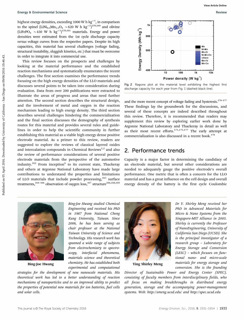
Fig. 2 shows the Ragone plot of the highest capacitiesexhibited in each respective year where energy and powerdensities are plotted showing performance capabilities at thematerial level. In general, this class of materials exhibit the
Fig. 1 Evolution of the discharge capacity by years of Mn,6,73–77 Ni–Mn,5,78–113 Mn–Cr,114–124 Ni–Mn–Co7–72 Mn–Fe,125–135 Mn–Co,136–140
and other143–156 lithium rich positive electrode materials.
Sunny Hy
Dr Sunny Hy received his BS degreein chemical engineering from theUniversity of Utah and his PhDdegree from the National TaiwanUniversity of Science and Tech-nology in chemical engineering.He then worked as a postdoctoralscholar at the University ofCalifornia, San Diego where hisresearch focused on advancedlithium ion battery materials,all solid state batteries, andadvanced materials charac-terization techniques.
Haodong Liu
Haodong Liu received his BS inChemistry from Xiamen University(2011). He is currently a PhDcandidate in the NanoengineeringDepartment at the University ofCalifornia San Diego (UCSD). Heis the founder of ElectrochemicalSociety – UCSD Student Chapter,which promotes the interest andadvancement of electrochemistryscience and technology amongboth graduate and undergraduatestudents at UCSD. His researchobjective is to diagnose, optimize
and design Ni and Mn based layered oxides as cathode materials fornext generation Li-ion batteries and Na-ion batteries.
Minghao Zhang
Minghao Zhang received his BSin Physics from Nankai University(2009), and MS in MaterialsPhysics and Chemistry fromChinese Academy of Sciences(2012). He is currently a Ph.D.candidate in Laboratory forEnergy Storage and Conversion(LESC) at the University ofCalifornia, San Diego. Hisresearch interests includeadvanced lithium-ion and postlithium-ion batteries based onnovel types of electrode materials.
Danna Qian
Dr Danna Qian received herPhD in NanoEngineering fromthe University of California, SanDiego, in 2015, after which sheworked as a postdoc researcherfor a year. Her research focuseson combining high-end charac-terization techniques with compu-tations for better design of cathodematerials in alkaline ion batteries.
Review Energy & Environmental Science
Publ
ishe
d on
05
Apr
il 20
16. D
ownl
oade
d by
Uni
vers
ity o
f C
alif
orni
a -
San
Die
go o
n 09
/06/
2016
19:
46:4
3.
View Article Online
This journal is©The Royal Society of Chemistry 2016 Energy Environ. Sci., 2016, 9, 1931--1954 | 1933
highest energy densities, exceeding 1000 W h kg�1, in comparisonto the spinel (LiNi0.5Mn1.5O4 B620 W h kg�1)159,160 and olivine(LiFePO4 B430 W h kg�1)159,161 materials. Energy and powerdensities were estimated from the 1st cycle discharge capacityversus voltage curves from the respective papers. Despite its highcapacities, this material has several challenges (voltage fading,structural instability, sluggish kinetics, etc.) that must be overcomein order to integrate it into commercial use.
This review focuses on the prospects and challenges bylooking at the material performance and the establishedreaction mechanisms and systematically enumerates the recentchallenges. The first section examines the performance trendsfocusing on the high energy densities of the LLO materials anddiscusses several points to be taken into consideration duringevaluation. Data from over 200 publications were extracted toillustrate the areas of progress and areas that need furtherattention. The second section describes the structural design,and the involvement of metal and oxygen in the reactionmechanism leading to high energy density. The third sectiondescribes several challenges hindering the commercializationand the final section discusses the demography of synthesisroutes for this material and provides several rules and guide-lines in order to help the scientific community in furtherestablishing this material as a viable high energy dense positiveelectrode material. As a primer to this review, readers aresuggested to explore the reviews of classical layered oxidesand intercalation compounds in Chemical Reviews1,2 and alsothe review of performance considerations of several positiveelectrode materials from the perspective of the automotiveindustry.162 From inception6 to its current state, Thackerayand others at Argonne National Laboratory have made largecontributions to understand the properties and limitationsof LLO materials that include powder processing,163 surfacetreatments,164–166 observation of oxygen loss,167 structure166,168,169
and the more recent concept of voltage fading and hysteresis.170–177
These findings lay the groundwork for the discussions, andseveral of these concepts are indeed described throughoutthis review. Therefore, it is recommended that readers maysupplement this review by exploring earlier work done byArgonne National Laboratory and Thackeray in detail as wellas their most recent efforts.171,173,177 The early attempt atcommercialization is also discussed in a recent book.178
2. Performance trends
Capacity is a major factor in determining the candidacy ofan electrode material, but several other considerations areneeded to adequately gauge the positive electrode’s overallperformance. One metric that is often a concern for the LLOmaterial and has a great influence on the cell design and overallenergy density of the battery is the first cycle Coulombic
Fig. 2 Ragone plot at the material level exhibiting the highest firstdischarge capacity for each year from Fig. 1 (dashed black line).
Bing-Joe Hwang
Bing-Joe Hwang studied ChemicalEngineering and received his PhDin 1987 from National ChengKung University, Taiwan. Since2006, he has been serving aschair professor at the NationalTaiwan University of Science andTechnology. His research work hasspanned a wide range of subjectsfrom electrochemistry to spectro-scopy, interfacial phenomena,materials science and theoreticalchemistry. He has established bothexperimental and computational
strategies for the development of new nanoscale materials. Histheoretical work has led to a better understanding of reactionmechanisms of nanoparticles and to an improved ability to predictthe properties of potential new materials for ion batteries, fuel cellsand solar cells.
Ying Shirley Meng
Dr Y. Shirley Meng received herPhD in Advanced Materials forMicro & Nano Systems from theSingapore-MIT Alliance in 2005.Shirley is currently the Professorof NanoEngineering, University ofCalifornia San Diego (UCSD). Sheis the principal investigator of aresearch group – Laboratory forEnergy Storage and Conversion(LESC) – which focuses on func-tional nano- and micro-scalematerials for energy storage andconversion. She is the founding
Director of Sustainable Power and Energy Center (SPEC),consisting of faculty members from interdisciplinary fields, whoall focus on making breakthroughs in distributed energygeneration, storage and the accompanying power-managementsystems. Web: http://smeng.ucsd.edu/ and http://spec.ucsd.edu
Energy & Environmental Science Review
Publ
ishe
d on
05
Apr
il 20
16. D
ownl
oade
d by
Uni
vers
ity o
f C
alif
orni
a -
San
Die
go o
n 09
/06/
2016
19:
46:4
3.
View Article Online

1934 | Energy Environ. Sci., 2016, 9, 1931--1954 This journal is©The Royal Society of Chemistry 2016
efficiency where the discharge capacity may be considerablylower than the corresponding charge capacity. Fig. 3 shows thefirst discharge capacity of the LLO materials versus the 1st cycleCoulombic efficiency. The Coulombic efficiency was extractedby taking the values directly reported from each respectivepaper. A dashed line at 0.8 is shown to illustrate that, unlikeLiNi0.5Mn1.5O4 or LiFePO4, the LLO materials generally have alarge distribution of the 1st cycle efficiencies. Each of the majormetal systems shows a broad distribution of efficiencies, withno particular system showing greater reversibility over the otherbased purely on the base metals. Several factors contribute tothe 1st cycle efficiencies, with oxygen involvement being amajor contributor. While it is important to achieve a first cycleCoulombic efficiency close to 1, if this is not achievable,a consistent and high Coulombic efficiency is also equallyimportant with respect to electrode balance (positive to negative)and design. Several of these factors will be discussed later in thisreview.
Capacity retention has also been a point of contention forthe assessment of lifetime where capacity fading may not occuruntil considerably long cycling at a reasonably slow C-rate(4100 cycles and C/3 or lower) has been done. Several studieson the LLO material select a cut-off of o100 cycles with variableC-rates where capacity fading may not be as severe, withthe exception of high temperature cycling that may catalysecapacity fading. Such cycling protocols are not inadequate inassessing electrochemical behaviour, but the results should beviewed cautiously. In addition, cycle-to-cycle procedures alsovary the fading behaviour. Adoption of an IR-corrected cyclingprotocol or related standard tests may be considered whichwould provide a more robust determination and measure forthe different fading behaviours.171,177 4100 cycles serve, at thevery least, as a first approximation in gauging the capacityretention as some researchers have illustrated in their respec-tive studies.35,39,41,42,44,59,60,63,69,107,112,114,140,156,179 Fig. 4 showsa comparison between materials cycled o100 cycles (top) and4100 cycles (bottom). Capacity retention was measured against
the first cycle with the same C-rate after material activation(material activation protocols generally have the first 3 cycles ata relatively slow rate in order to ensure adequate activation).It should be noted that the C-rate for the retention tests ofthe different materials was not explicitly shown but was below0.5 C. General trends indicate that higher C-rates deliver betterretention at the cost of capacity compared to slower C-rates.For the LLO materials cycled o100 cycles, the majority showa retention of 480% of their first discharge capacity. Becausethe relationship between capacity fading and cycle number isnonlinear, it may not be appropriate to identify whether aparticular LLO material has superior or poor capacity retention.Interestingly, several materials also exhibit capacities wellbeyond 100% retention that may also present some issues incyclability assessments.93,95,138,140 The increasing cycle effi-ciency is largely related to either the material composition orlarger particle size, which causes an incremental growth fromlower initial capacities with cycle number due to slow kinetics,activation, or alteration to hysteretic behavior.176,180 This is notan ideal case considering the cycle to cycle variants when amore consistent capacity with each cycle is preferred.
Fig. 4(bottom) plots discharge capacities versus cycle retentionfor studies that had cycled over 100 times. Again, we see materialsthat exhibit retention 480% with capacities from 150 mA h g�1
to 270 mA h g�1. Promisingly, several materials exhibit capacities
Fig. 3 Discharge capacity versus first cycle efficiency. The dashed lineat 0.8 is a reference point to show the large distribution of efficiencieswhere a number of factors contribute to the low first cycle efficiencythat may include oxygen involvement, metal migration, and/or electrolytedecomposition.
Fig. 4 Stable capacity at the specific end cycle (number of cyclesindicated by open circle size) versus % capacity retention for materialscycled o100 cycles (top) and 4100 cycles (bottom).
Review Energy & Environmental Science
Publ
ishe
d on
05
Apr
il 20
16. D
ownl
oade
d by
Uni
vers
ity o
f C
alif
orni
a -
San
Die
go o
n 09
/06/
2016
19:
46:4
3.
View Article Online

This journal is©The Royal Society of Chemistry 2016 Energy Environ. Sci., 2016, 9, 1931--1954 | 1935
over 200 mA h g�1 after 4300 cycles that correspond to aretention of 475%.39,59,60,63,69,112,140 Zheng et al.179 showed a77% capacity retention of 165 mA h g�1 after 500 cycles. Whilethe capacity was low, the severe capacity fading was substantiallyreduced. Again, this should be looked at with caution but doesshow the retention capabilities of the LLO material and alsobetter represents the cycle life of the LLO material that movescloser to cell targets of 1000 cycles at C/3.4 It should be noted thatcell types such as coin cell or pouch cell types may also have alarge effect on the cycle life testing. Electrode and cell designshave a substantial impact on cycle life and must also be con-sidered in the final design consideration for material evaluation.One of the great challenges for this material that has largelyplayed in the premature cyclability assessment is voltage fading.Although minimal capacity fading can be observed over longcycling protocols, the average voltage decreases over severalcycles, leading to a severe drop in the energy density. To illustrate,taking into account the average voltage and the rate at which theLLO material was cycled, a Ragone plot at the material level ofthe 4100 cycle studies is shown in Fig. 5. In comparison to theRagone plot in Fig. 1 where the initial energy densities were over1000 W h kg�1 at power densities of B100 W kg�1, the energydensity after cycling 4100 cycles shows a considerable drop inthe range of roughly 800 down to 500 W h kg�1 at the same powerdensity. Considering that most of the materials in Fig. 5 had aninitial energy density of B1000 W h kg�1, this decrease in energydensity that was not represented completely by retention orcapacity alone illustrates that a careful consideration of theelectrochemical performance of the LLO is needed. In addition,similar to the related performance plots, the Co–Mn systemexhibits relatively high energy density and power density after103 cycles, but due to the incremental increase with each cycle,its performance also varies with every cycle.137,140 While Fig. 5illustrates the challenge in overcoming and assessing voltagefading, it also shows that the LLO material still shows greatpromise with energy densities of B800 W h kg�1 in a Ni–Mn–Co
system39 and a Ni–Mn system112 as well as corresponding powerdensities that could reach close to 1000 W kg�1 after 4100 cycleswith reasonable energy densities in a Ni–Mn–Co system.42 As aguideline, it is recommended, in addition to discharge capacitiesversus cycle number, that average potentials or energy densitiesshould also be reported. Also, cyclability measurements shouldbe extended beyond 100 cycles at moderate current rates orutilizing more standardized protocols.171,177
With considerable improvement in capacities over the yearsand examples of retention after long cycling, this materialshows great promise as the next generation positive electrodematerial for electric vehicles. However, as illustrated above,further improvements in voltage stability, irreversible capacity,and rate capability are needed. Cost-effective and easily adop-table methods and materials would be ideal. A fundamentalunderstanding of the material and its related reactions andinteractions with other parts of the battery would provideinsight into the thermodynamic and kinetic drivers relatedto stability and fast rate charging. The following section willdescribe the LLO material’s structure and the reaction mechanismsthat drive high capacities.
3. Material structure and reactionmechanisms3.1. Phase segregation and metal distribution
The LLO materials, often denoted as (1 � y)Li2MnO3�LiTMO2
(TM = Mn, Co, Ni), have been described as either a composite ora solid solution of the rhombohedral LiMO2 (R%3m space group)and monoclinic Li2MnO3 structures (C2/m space group). Alter-natively, the Li2MnO3 can be written as Li[Li1/3Mn2/3]O2 todescribe both structures as layered a-NaFeO2-type rock saltstructures with cation ordering or long-range Li in-plane order-ing and a O3ahex � O3ahex superstructure in the TM layer.78,181
While there is evidence for both the composite and solidsolution structures,79,90,166,168,182–187 the debate concerningthe pristine structure still has not reached a conclusion.However, there is some evidence that the pristine structureis largely dependent on composition and synthesis condi-tions.35,112,183–185,188–190 Utilizing a solution-based combinatorialapproach,191 McCalla et al. studied large arrays of compositionswithin the Gibb’s triangle for the Li–Mn–Co–O (Fig. 6a and b) andLi–Mn–Ni–O (Fig. 6c and d) systems under different coolingrates.188,190
For the Li–Mn–Co–O system,188 a solid solution extendingthe entire composition line between Li2MnO3 and LiCoO2 doesshift when samples are heat treated at different temperaturesand subsequently quenched or slowly cooled where the identifi-cation of multiple phases including the layered–layered phaseseparation was through peak broadening in X-ray diffractionpatterns. Bareno et al. have observed this nanoscale phasesegregation in the non-quenched Li1.2Co0.4Mn0.4O2 usingextended X-ray absorption fine structures.168 Similarly, thenanoscale phase segregation of the Li–Mn–Ni–O system has astrong dependence on cooling rates where the boundaries
Fig. 5 Ragone plot of lithium rich positive electrode materials aftercycling over 100 cycles with circle size indicating the number of cycles(from 103 to 500 cycles). Relative to Fig. 1, the materials that exhibitedsimilar energy densities of B1000 W h kg�1 show a significant decreaseafter extended cycling over 100 cycles largely due to the voltage fadingprocess.
Energy & Environmental Science Review
Publ
ishe
d on
05
Apr
il 20
16. D
ownl
oade
d by
Uni
vers
ity o
f C
alif
orni
a -
San
Die
go o
n 09
/06/
2016
19:
46:4
3.
View Article Online

1936 | Energy Environ. Sci., 2016, 9, 1931--1954 This journal is©The Royal Society of Chemistry 2016
within the diagram can move dramatically, although key featuresin the phase diagram remain constant.190 Interestingly, a distinct‘‘bump’’ can be observed near the Li2MnO3 region of the diagramsuggesting metal-site vacancy (Li and/or TM) within Li-deficientstructures. This was confirmed by Monte Carlo simulation, X-raydiffraction, and redox titration where the presence of vacanciesmay promote the formation of a solid solution.189 While the roleof vacancies in the electrochemical behaviour is still not wellunderstood, it has been suggested that they may have a positiveimpact on lowering the irreversible capacity.192 The route-dependent phase segregation has also been observed at theatomic level using electron microscopy and X-ray energy disper-sive spectroscopy to observe the nanoscale phase separation andselective surface cation segregation in pristine Li1.2Ni0.2Mn0.6O2
after high temperature calcination (Fig. 7).35,193 Zheng et al.showed that an uniform distribution of TMs which exhibits asolid solution-like C2/m monoclinic symmetry could be achievedwhen they applied a hydrothermal synthesis route. The hydro-thermally synthesized LLO material with uniform TM distributionshowed much improved cycling retention with minimal voltagefading when compared to the phase segregated LLO materialscycled for 200 cycles (Fig. 7).112
With these recent findings, it is apparent that the differentsynthesis parameters as well as the materials characterizationmethods for pristine LLO materials must be heavily scrutinizedas they have a large impact on the overall battery performance.A discussion on material design and synthesis routes with somesynthesis guidelines is elaborated and provided later in thisreview.
Over the past 20 years, the LLO has been extended to othermetal systems beyond the Li–Mn–Co–Ni–O containing com-pounds where the typical structure consists of alternating layersof Li and TM layers where the Li and TM layers exhibit the samein-plane ordering in the TM layer with the oxygen close-packedlayers stacked with O3 symmetry.116,125,132,144,149–151,153,158,194–196
Recently, disordered Li-excess materials have been shown toexhibit facile Li diffusion not limited to the structure, as it is thecase for well-ordered materials.122,196–198 The facile ion diffusionis made possible by a percolating network of 0-TM channelsof no face sharing TM ions made more easily accessible with alocal Li-rich domain. As illustrated in Fig. 8 the percolationprobability dramatically increases once the Li content reaches41.1 without traversing through 1 or 2 TM ion199 face sharingion channels.122,198 These phenomena and a new class ofdisordered Li-excess materials have been extended to othermetal systems197,200 and are expected to expand and be appliedto other new and existing systems in the near future.
3.2. Activity of oxygen and transition metals
Similar to the classical Li layered oxides, the LLO materialsfollow the solid-state redox chemistry of TM3+/4+ or TM2+/3+/4+
with simultaneous extraction/insertion of Li ions at the onset ofcharge compensation mechanism in the LLO system. However,based on this model, experimentally observed capacities cannotbe fully accounted for by the available TM redox pairs. Indeed,Ohzuku et al. showed capacities up to 350 mA h g�1 for theirseries of trials at high temperature cycling for the Li1.2Ni0.2Mn0.6O2
attributing relatively low capacities at room temperature to besolely limited by kinetics (Fig. 9a). By applying a low current,capacities approaching 300 mA h g�1 at room temperature wereshown, which illustrated that the electrochemical reactions thatdetermine the reversible capacities are indeed under kineticcontrol (Fig. 9b).5 For Li1.2Ni0.2Mn0.6O2, 126 mA h g�1 ofreversible capacity can be accounted for the Ni2+/4+ redoxcouple. While the further oxidation of Mn4+ to high valencestates cannot be ruled out and has been suggested as apossibility, this has not been experimentally observed. Instead
Fig. 6 The entire Gibbs phase diagrams for Co–Mn (a and b) heated in airand Ni–Mn (c and d) heated in oxygen to 800 1C and then subsequentlyquenched (a and c) or subjected to regular cooling (b and d).188–190
Fig. 7 Z-contrast image and XEDS maps of multiple Li1.2Ni0.2Mn0.6O2
nanoparticle aggregates; (a) Z-contrast image, (b) Ni, (c) overlaid Ni andMn, and (d) Ni/(Mn + Ni) atomic percentage quantification maps.35
Z-contrast image and XEDS map of overlaid Ni/Mn particles synthesizedby (e) co-precipitation, (f) sol–gel, and (h) hydrothermal methods with(i) corresponding average voltage versus cycle number.112
Review Energy & Environmental Science
Publ
ishe
d on
05
Apr
il 20
16. D
ownl
oade
d by
Uni
vers
ity o
f C
alif
orni
a -
San
Die
go o
n 09
/06/
2016
19:
46:4
3.
View Article Online

This journal is©The Royal Society of Chemistry 2016 Energy Environ. Sci., 2016, 9, 1931--1954 | 1937
the proposed participation of a distinct redox chemistry of theoxygen ion, O2
n�, in the redox processes has been recentlyfound to explain the high capacities exhibited by the LLOmaterials.5,150,151,201–205 This oxygen participation is distinctfrom the irreversible release of oxygen to form oxygen gasand/or react with the electrolyte that may often occur nearthe region of anionic redox activity.32,86,206–210
The reversible anionic redox of oxygen ions can be explainedby the strong metal (d) to ligand (p) hybridization betweenthe orbitals of TM ions and oxygen ions and the formation ofhighly oxidized metals plus holes on the oxygen. As depicted inFig. 10a, a schematic representation of the density of states ofLi2MnO3, Li2RuO3, and Li2�xRu1/2Mn1/2O3, Sathiya et al. showsthat Ru4+ is oxidized to Ru5+ with the removal of 0.5 Li andfurther removal of Li further oxidizes Ru5+ to a state of Ru5+ + h+
within the O2� band.150 Their XPS results show the reversibleformation of lattice O2
n� via a peak at B530.5 eV within theXPS O 1s core peaks. This peak corresponds well to an ‘‘O’’species, which showed lower electronic density than O2� ions.This component was found after charging to 4.6 V and thendisappeared after discharging to 2 V (Fig. 10b).150 This was alsoaccompanied by structural reorganization with the reductionof Mn after discharging, which is common within the LLOmaterials after high voltage cycling.91,99,211–213 The reversibleformation of O2
n� species was further confirmed in theLi–Ru–Sn–O system using a combination of XPS, ex situ electronparamagnetic resonance (EPR), and DFT calculations wherereductive coupling of highly oxidized Ru6+ forms Ru5+ or Ru4+
coordinated with hole containing oxygen (O2n�) (Fig. 11f).151
Furthermore, unlike Mn, the observed spectator ion (Sn) showedno reduction upon cycling, which they attributed to the largeSn4+ cation. Indeed, similar reduction of TMs at the plateau hasalso been observed in other metal systems where the spectatorions are involved via reduction.91,99,194,195,211,214 This was thenagain confirmed by operando EPR in the Li–Ru–Sn–O systemshowing the presence of the reductive coupling mechanisms
Fig. 8 (A) Computed probability of finding a percolating network of 0-TMchannels (color) versus Li content (x in LixTM2�xO2) and cation mixing(TMLi layers/TMTM layers � 100%). (B) Accessible Li content by a percolating0-TM network (color) versus Li content and cation mixing. (C) o–t–odiffusion where two tetrahedral paths connect each pair of neighboringoctahedral sites. The activated state can share faces with (D) no octahedraltransition metals, (E) one transition metal, or (F) two transition metals.122
Fig. 9 The effect of current on the discharge capacity of Li[Li1/5Ni1/5Mn3/5]O2
examined in a lithium cell at room temperature. The cell was charged to5.0 V at a constant current of 0.15 mA cm�2 (9.7 mA g�1) and then keptat 5.0 V until the current decreased to 0.025 mA cm�2, the so calledCCCV-charging mode, and then discharged at (a) 1.65 mA cm�2
(106.5 mA g�1), (b) 1.05 (67.8), (c) 0.3 (19.4), (d) 0.15 (9.7), or (e) 0.075 (4.8).Electrode mix used is 35.2 mg weight and 101 mm thick.5
Fig. 10 (a) Schematic representation of the density of states (DOS).(b) XPS spectra of Mn 3p–Li 1s, Ru 3p, and O 1s core peaks of(1) Li2Ru0.5Mn0.5O3 pristine material, (2) after the charge of 4 V, (3) afterthe charge of 4.6 V, and (4) after the discharge of 2 V.150
Energy & Environmental Science Review
Publ
ishe
d on
05
Apr
il 20
16. D
ownl
oade
d by
Uni
vers
ity o
f C
alif
orni
a -
San
Die
go o
n 09
/06/
2016
19:
46:4
3.
View Article Online

1938 | Energy Environ. Sci., 2016, 9, 1931--1954 This journal is©The Royal Society of Chemistry 2016
indicated by a decrease in the Ru5+ signal and a new weak signalrelated to oxygenated species, possibly due to oxygen holeswithin the oxygen-2p orbitals.215
Fig. 11 shows the molecular orbital diagram of the relatedoxygenated species (O2)n� with the holes having antibondingcharacteristics. The extraction of electrons from highly oxidizedRu5+ and O2� ligands during the oxygen activation plateauforms the Ru5+–O2
3� or O2� ligand. Upon discharge, this
process was observed to be reversible. Besides the irreversibilityfrom the oxygen gas evolution, there is a degree of irreversibilitythat is attributed to the formed oxygenated species.194,195
Fig. 12a depicts the density of states for the possible involvementof oxygen for three different metal systems. In the classicalintercalation compounds, besides oxygen evolution at certainlithium concentrations, charge compensation involves mostlythe metal redox pairs where all electron density is attributed tothe M d-band. For the formation of peroxo/superoxo species, thisoccurs with highly oxidized metal cations with the addition ofholes within the oxygen band.
Finally, the evolution of oxygen occurs when the majority ofthe electron density near the Fermi level is from oxygen p-levelswhere continued extraction of lithium forms O–O dimers thatsubsequently form oxygen gas.194 McCalla et al. in a study onLi4FeSbO6 found that metal and anion redox reactions occur ata distinct plateau that is separated from the oxygen gas evolvingplateau that is followed by the reductive coupling mechanismoccurring along with oxygen gas evolution (Fig. 12).195 Interest-ingly, they suggest that with the reduction of the metal backto its pristine oxidation state during the reductive couplingprocess, all or a majority of the capacity at the maximallycharged state is stored solely in the oxygen. They also showedthat the oxygen related species exhibited 30% irreversibility,although they did not determine which of the oxygenatedspecies contributed to the irreversible process. The root cause
for this irreversibility in the oxygenated species is still unclear.Several questions are still left related to the involvementand reversibility of oxygen. Does oxygen come back? In whatforms does oxygen come in? Can we quantify it? What is thespeciation? While the unconventional anion participationallows for higher capacities to be reached, it also contributesto several challenges that impede Li mobility and stability.The next section will focus on several challenges necessary toovercome to fully utilize its high capacity characteristics.
4. Challenges for high energy density
Within the last ten years, a certain amount of fundamentalstudies have been carried out aiming at understanding thecomplex reactions and structural evolutions of the LLO mate-rial upon electrochemical cycling, in particular, the studies thatculminate as irreversible processes.32,80,86,98,173,182,210,216–221 Inthis section we will discuss the irreversible loss of latticeoxygen, its impact on the electrode/electrolyte interface, andhow the Li ion and TM ion migration induces the gradualevolution of surface and bulk structure of the LLO material.
4.1. Surface-related reactions and mechanisms
The most significant feature of the Li-rich layered oxide is thelong oxygen activation plateau, which only appears at its first
Fig. 11 (a–e) Schematic representation of the O2 molecular orbitaldiagram for the oxygenated species (O2)n�.215 (f) Schematic diagramshowcasing the reductive coupling mechanism.151,215
Fig. 12 (a) Schematic diagram of the density of states of the differentpossible participation of oxygen.194 (b) Schematic representation of themechanisms involved during electro-chemical cycling of Li4FeSbO6. Eachcircle represents a typical particle, with the red outline being used toindicate that the surface is prone to electrolyte reaction at low voltagebelow 3.0 V. Of particular importance is the reductive couple acting oniron when sufficient oxygenated species are present in the sample.195
Review Energy & Environmental Science
Publ
ishe
d on
05
Apr
il 20
16. D
ownl
oade
d by
Uni
vers
ity o
f C
alif
orni
a -
San
Die
go o
n 09
/06/
2016
19:
46:4
3.
View Article Online

This journal is©The Royal Society of Chemistry 2016 Energy Environ. Sci., 2016, 9, 1931--1954 | 1939
charge when the cut-off voltage is set to be more than 4.6 Vfor the Ni–Mn–Co systems and its derivatives.80,182 This oxygenactivation plateau consists of participation of a reversibleO2
n�/2O2� redox process and an irreversible loss of latticeO2�.86,151,215 The reversible process has been thoroughly dis-cussed in the previous sections, which contributes to the highcapacity of the Li-rich layered oxide. However, the irreversibleloss of lattice O2� is the origin of a series of surface reactionsand irreversible structural changes upon electrochemical cycling.In 2002, Lu et al. first proposed the lattice oxygen loss, andattempted to quantify the oxygen deficiency via XRD wherethey found 13.5% oxygen deficiency in the LLO material(Li[NixLi(1/3�2x/3)Mn(2/3�2x/3)]O2, x = 1/6), which has beencharged to 4.8 V.80 Later, in 2006, Armstrong et al. directlyobserved the generation of O2 gas during this plateau by in situdifferential electrochemical mass spectrometry (DEMS) thatwould subsequently cause cooperative displacement of TMdiffusing from the surface to the bulk, observed in neutronpowder diffraction.86 With the advancement of powerful charac-terization techniques, researchers have gained more insightsinto the irreversible loss of lattice O2� and its role in the surfacestructure/chemistry transformations. Yabuuchi et al. performeddetailed studies using synchrotron XRD, X-ray absorption spectro-scopy (XAS), X-ray photoelectron spectroscopy (XPS), and time-of-flight secondary ion mass spectroscopy (TOF-SIMS) showing theformation and deposition of Li2CO3 and oxygen-related species,which they believe are by-products of the oxygen reductionreaction to form a superoxide upon discharge below 3 V.32
Fig. 13 shows the TOF-SIMS spectra of LixNi0.13Co0.13Mn0.54O2�dafter charging to 4.8 V and discharging to 2 V (Fig. 13a) whereLi2O+ and LiC2
+ signals appear and subsequently disappear whenrecharged to 4.8 V (Fig. 13b). They attributed these two fragmentsto possible reduction products from the oxygen molecule.32 Zhenget al., performing in situ DEMS, not only observed O2 evolutionbut also a greater formation of CO2 during the high voltageplateau for Li[Li0.2Mn0.54Ni0.13Co0.13]O2 as seen in Fig. 14a andb.218 Hong et al. observed similar gas formation with the evolutionof O2, CO2 and CO for the first cycle and CO2 and CO forsubsequent cycles with in situ DEMS for the Li1.2Ni0.2Mn0.6O2
positive electrode. They also observed the continuous decomposi-tion and formation of Li2CO3 upon charging to 4.8 V anddischarging to 2 V using FTIR for multiple cycles (Fig. 13c),respectively.208 They attribute the loss of lattice oxygen andformation of CO2, CO, and Li2CO3 to the formation of oxygenradicals from oxygen gas reduced at the conductive surface of theelectrode. In addition, these oxygen radicals would then react withthe electrolyte (ethylene carbonate solvent and LiPF6 salt) to formH2O by-products. These by-products subsequently react to forman acidic species (HF) that corrodes the surface of the positiveelectrode and leads to dissolution of Mn.
Hy et al. performed in situ surface-enhanced Raman spectro-scopy (SERS) on Li2MnO3, LiNi0.5Mn0.5O2, and Li1.2Ni0.2Mn0.6O2
positive electrodes and observed the generation of Li2CO3 andLi2O for the oxygen evolving materials (L1.2Ni0.2Mn0.6O2 andLi2MnO3).210 For Li1.2Ni0.2Mn0.6O2, the formation of Li2O wasobserved to occur during the oxygen activation plateau which
subsequently is consumed towards the end of charge (Fig. 14cand d). Li2O subsequently reacts with the acidic species (HF) toform H2O that subsequently solvates the negative electrode (C6)to form LiOH at the negative electrode changing its SEI.Changes within the electrolyte pH environment as a result oflattice O2� loss were also observed.210 These side products areformed from the complex reactions taking place betweenoxygen-related species, the organic electrolyte, and the elec-trode surfaces, which are driven by the high charge potential.Strategies for suppression of the irreversible oxygen evolution
Fig. 13 TOF-SIMS spectra32 of cycled LixNi0.13Co0.13Mn0.54O2�d (a) dis-charged to 2 V and (b) recharged to 4.8 V with Li2O+ and LiC2
+ signaturesat the discharged state and (c) FTIR spectra of the Li1.2Ni0.2Mn0.6O2
electrodes with Li2CO3 reference showing decomposition and reforma-tion of Li2CO3 after being charged and discharged, respectively.208
Fig. 14 DEMS measurements for (a) O2 evolution and (b) CO2 evolutionfor Li[Li0.2Mn0.54Ni0.13Co0.13]O2.218 In situ SERS during (c) charging and(d) discharging for Li[Li0.2Ni0.2Mn0.6]O.
Energy & Environmental Science Review
Publ
ishe
d on
05
Apr
il 20
16. D
ownl
oade
d by
Uni
vers
ity o
f C
alif
orni
a -
San
Die
go o
n 09
/06/
2016
19:
46:4
3.
View Article Online

1940 | Energy Environ. Sci., 2016, 9, 1931--1954 This journal is©The Royal Society of Chemistry 2016
or a means to protect the surface of the electrodes whilepromoting the participation of the anion redox pair will likelybe the key to increase the cycle stability of the LLO material.Further studies of the complex mechanism that occurs at theelectrode/electrolyte interface as well as quantification of thecontribution made by each process to the reversible andirreversible capacity will undoubtedly spur the developmentof the LLO as a positive electrode material. However, while thereactions related to the surface chemistry are important,equally important are the structural changes occurring at thesurface and bulk that are also tied to the dynamic changes inoxygen within the lattice.
4.2. Subsurface structural changes and correlation withperformance issues
Electron microscopic techniques have further pushed ourunderstanding of the surface phenomena for the LLO materials.The combination of scanning transmission electron microscopyand electron energy loss spectroscopy (STEM/EELS) has proven tobe a powerful tool to obtain structural and chemical informationat the atomic scale.98,219,222 Qian et al. performed DFT calcula-tions and STEM/EELS on the positive electrode materialLi[Li1/6Ni1/6Co1/6Mn1/2]O2 to understand the role of oxygenvacancies in cation migration during charging and discharging.EELS spectra in Fig. 15 show the O K edge of the Li-rich layeredoxide after the first cycle, from the bulk to the surface.219 Theirresults indicate the formation of oxygen vacancies near thematerial surfaces and sub-surfaces at 5–6 atomic layers whereTM ion migration only occurs near these vacancies. Bulktheoretical calculations on the formation of oxygen vacanciesin different atomic configurations indicate a strong preferencefor the Li–Ni–Mn local environment in the transition metallayer. A transition state theory was subsequently used todescribe the migration mechanism of Ni and Mn ions wherethe diffusion barrier in the presence of vacancies is lower
relative to no vacancies and the specific location of the oxygenvacancies has a significant impact on the diffusion barrier. Dueto the alteration of the O-coordination in the presence ofoxygen vacancies Ni or TM ions become unstable and sponta-neously migrate to a fully coordinated site near the lithiumlayer.219 In contrast, Delmas et al. proposed a densificationmodel, in which there is TM ion migration from the surfaceto the bulk with the elimination of oxygen vacancies.86,217
Whether or not oxygen vacancies are eliminated during cyclingis still under debate. The rearrangement of cations on thesurface is another consequence of lattice O2� loss with thereduction of surface TM ions, including those seen in theNi–Co–Mn systems. XPS and soft-XAS, which are surface sensitivetools, have been used to capture the reduced TM ions on thesurface and subsurface at highly charged states.99,214,223 As aconsequence, the diffusion rates of the surface TM ions wouldlikely be higher than their high oxidation state counterparts. Theloss of lattice oxygen would likely form vacancy sites and inducethe reduction of surface TM ions, with both factors facilitatingthe migration of TM ions to the Li layer.
More STEM related studies have been carried out on the LLOmaterial after electrochemical cycling. Yan et al.,224 usingSTEM-EELS, studied the Li1.2Ni0.2Mn0.6O2 positive electrodematerial and determined chemical and structural changeswithin two distinct layers: (1) Ni-rich and lithium deficientlayers and (2) layers that are prone to surface structuralchanges. They found a sequential surface structural changefrom C2/m - I41 - Mn3O4-spinel due to the progressiveTM enrichment and Li depletion with increasing cycles up to100 cycles (Fig. 16). Upon cycling, the formation of pits andcracks on the material occurs more prominently at specificfacets (typically (200) and (202) planes), while others, such asthe (002) plane, are highly resistant to these corrosions. Extrastructural ordering also occurs with cycling indicated by theadditional spots (blue arrows in Fig. 16) in the fast Fouriertransform images. In addition, the chemical compositionchange between Ni-rich and surface structural layers was distin-guished in which the Ni-rich layers tend to maintain a relativelyconstant thickness while the surface structural layer tends togrow with increasing cycles. Other researchers reported theobservation of rock-salt and spinel phases with electrochemicalcycling where the spinel phase has been observed even in thebulk.107,169,224,225 In contrast, Carroll et al. showed no increaseof the spinel-like phase up to 10 cycles for the LLO material,223
and Boulineau et al. reported the growth of the surface spinelphase starting after the 1st cycle with the thickness of the phaseremaining at 2–3 nm after 50 cycles and beyond.226
Using STEM equipped with a high angle annular dark field(HAADF) detector and EELS on the LLO LixMn0.61Ni0.18Mg0.01O2
positive electrode material, Boulineau et al. observed a surfaceNi gradient that is progressive with increasing cycling due tothe migration of Mn from the surface to the bulk and ascribedthis phenomenon to the partial structural densification withMn progressively occupying the vacant lithium sites of the slabswithout excluding the possibility of surface Mn dissolution(Fig. 17).226 The resulting surface transformation and the
Fig. 15 Spatially resolved O K-edge EELS spectra from the bulk to thesurface.219
Review Energy & Environmental Science
Publ
ishe
d on
05
Apr
il 20
16. D
ownl
oade
d by
Uni
vers
ity o
f C
alif
orni
a -
San
Die
go o
n 09
/06/
2016
19:
46:4
3.
View Article Online

This journal is©The Royal Society of Chemistry 2016 Energy Environ. Sci., 2016, 9, 1931--1954 | 1941
positive electrode/electrolyte interface of LLO may also impedeLi diffusion between the electrode/electrolyte interface and thesurface/bulk interface.32,94,208,210,223 Additionally, the increasedimpedance of the cell and the deteriorated electrode/electrolyteinterface can cause capacity and voltage fading. The dissolution
of low oxidation state Mn ions should also be considered as asource of capacity loss.208
There has been great progression towards understandingand determining the surface structural transformation that isgenerally considered irreversible. However, continued efforts atelucidating the complexities and subtle nuances at differentlength scales will be necessary in order to formulate strategiesto mitigate these surface and subsurface structural changes.A better understanding of the specific composition of thesubsurface phases would be beneficial. Also, extending theobservation of the bare materials to ones that have beenmodified either with coatings, surface treatments, additives,or dopants would also shed more light on their specific role. Itwill also be necessary to distinguish, ideally quantitatively, thecontribution of surface changes from ones that are related tobulk changes that propagate outwards to the surface and onesthat are related to surface/electrolyte interface interactions. It isthen necessary to elucidate the phenomenon that encompassesthe bulk structure of the LLO materials.
4.3. Bulk structural changes and correlation withperformance issues
As mentioned in the first section, one of the most seriousproblems within the LLO materials is the capacity and voltagefading that occurs upon long cycling that continuouslydecreases the energy density and limits the practical applica-tion of these materials despite their high energy density in thefirst cycle.210,227,228 Performance can be easily misinterpreteddue to the nonlinear relationship between capacity and voltageloss (e.g. high capacities are still possible with voltage decay).
As shown in Fig. 18a, Gu et al. have correlated the layer tospinel phase transformation with voltage fading where thetransition is accomplished through the migration of TM ionsto the Li layer sites without lattice breakdown.229 In Fig. 18b,
Fig. 16 (a–d) Low magnification STEM-HAADF images to show cyclinginduced corrosion. Cracks and pits are highlighted by red arrows. The(002) surface planes show strong resistance to corrosion. (e–h) [010] zoneaxis SAED patterns. Extra diffraction spots appeared in cycled samples,which are highlighted by red and blue circles. Red circles indicate theformation of ordered structures. A (10�1) ordered plane is clearly seenafter cycling. Blue circles come from double diffraction. (i–l) High resolu-tion STEM-HAADF images to show the cycling induced structural changeon particle surfaces. Pristine samples (i) show a homogeneous structurefrom the surface to the bulk. Dashed lines in (j and k) highlight thethickness of the SRL. In (l), the whole areas were transformed. (m) [101]zone axis STEM-HAADF image and its fast Fourier transform image. Bluearrows indicate the ordered features of (20�2) planes and extra diffractionspots. (n) [010] zone axis STEM-HAADF image to show the spinel structureand the I41 structure in a sample cycled for 45 cycles.224
Fig. 17 High-resolution STEM-HAADF images, chemical maps, and plot of the evolution of the Mn and Ni atomic concentration obtained fromSTEM-EELS experiments after 50 charge–discharge cycles. Concentrations are obtained by averaging the composition over the width of the box whichcorresponds to one cell (a slab and an interslab). (a) At the C/2 rate. (b) At the C/10 rate. The white dotted lines highlight the transition between layeredand defect spinel structures located in the bulk and on the surface of the particles, respectively.226
Energy & Environmental Science Review
Publ
ishe
d on
05
Apr
il 20
16. D
ownl
oade
d by
Uni
vers
ity o
f C
alif
orni
a -
San
Die
go o
n 09
/06/
2016
19:
46:4
3.
View Article Online
1942 | Energy Environ. Sci., 2016, 9, 1931--1954 This journal is©The Royal Society of Chemistry 2016
a schematic diagram illustrates the relationship between hysteresisand voltage fading where they represent the reversible andirreversible processes that occur during cycling, respectively.171
The onset of voltage fading and hysteresis are intrinsic processeslinked to the activation of the Li2MnO3 component, which hasbeen correlated with the Li–Mn ordering.158,168,171,173,175–177,211,230
For hysteresis, cations that have migrated to tetrahedral sites fromoctahedral sites during the plateau now migrate back to octa-hedral sites once sufficient Li insertion has occurred duringdischarge. For voltage fading, changes in the local structure areinduced by the tetrahedral cations (Li-layer octahedral sites)migrating and occupying new sites that are not easily extracted.
DFT calculations,98 solid state NMR,91 and neutron diffrac-tion analysis231,232 have identified the extraction of Li ions fromthe TM layer, the formation of tetrahedral Li, and the migrationof TM from the octahedral site of TM layers to the tetrahedral/octahedral sites in the Li layer during the plateau.158,173,232,233
Recently, Sathiya et al. used TEM and XPCS to observe the onsetof voltage decay that occurs with the migration of Ti4+ intointerstitial tetrahedral sites within the Li2Ru1�yTiyO3 material.158
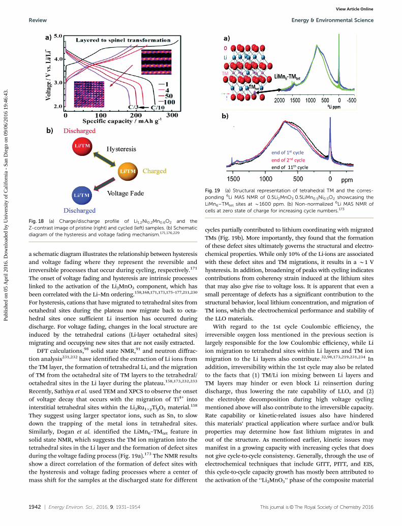
They suggest using larger spectator ions, such as Sn, to slowdown the trapping of the metal ions in tetrahedral sites.Similarly, Dogan et al. identified the LiMn6–TMtet feature insolid state NMR, which suggests the TM ion migration into thetetrahedral sites in the Li layer and the formation of defect sitesduring the voltage fading process (Fig. 19a).173 The NMR resultsshow a direct correlation of the formation of defect sites withthe hysteresis and voltage fading processes where a center ofmass shift for the samples at the discharged state for different
cycles partially contributed to lithium coordinating with migratedTMs (Fig. 19b). More importantly, they found that the formationof these defect sites ultimately governs the structural and electro-chemical properties. While only 10% of the Li-ions are associatedwith these defect sites and TM migrations, it results in a B1 Vhysteresis. In addition, broadening of peaks with cycling indicatescontributions from coherency strain induced at the lithium sitesthat may also give rise to voltage loss. It is apparent that even asmall percentage of defects has a significant contribution to thestructural behavior, local lithium concentration, and migration ofTM ions, which the electrochemical performance and stability ofthe LLO materials.
With regard to the 1st cycle Coulombic efficiency, theirreversible oxygen loss mentioned in the previous section islargely responsible for the low Coulombic efficiency, while Liion migration to tetrahedral sites within Li layers and TM ionmigration to the Li layers also contribute.32,98,173,219,231,234 Inaddition, irreversibility within the 1st cycle may also be relatedto the facts that (1) TM/Li ion mixing between Li layers andTM layers may hinder or even block Li reinsertion duringdischarge, thus lowering the rate capability of LLO, and (2)the electrolyte decomposition during high voltage cyclingmentioned above will also contribute to the irreversible capacity.Rate capability or kinetic-related issues also have hinderedthis materials’ practical application where surface and/or bulkproperties may determine how fast lithium migrates in andout of the structure. As mentioned earlier, kinetic issues maymanifest in a growing capacity with increasing cycles that doesnot give cycle-to-cycle consistency. Generally, through the use ofelectrochemical techniques that include GITT, PITT, and EIS,this cycle-to-cycle capacity growth has mostly been attributed tothe activation of the ‘‘Li2MnO3’’ phase of the composite material
Fig. 18 (a) Charge/discharge profile of Li1.2Ni0.2Mn0.6O2 and theZ-contrast image of pristine (right) and cycled (left) samples. (b) Schematicdiagram of the hysteresis and voltage fading mechanism.171,176,229
Fig. 19 (a) Structural representation of tetrahedral TM and the corres-ponding 6Li MAS NMR of 0.5Li2MnO3�0.5LiMn0.5Ni0.5O2 showcasing theLiMn6–TMtet sites at B1600 ppm. (b) Non-normalized 6Li MAS NMR ofcells at zero state of charge for increasing cycle numbers.173
Review Energy & Environmental Science
Publ
ishe
d on
05
Apr
il 20
16. D
ownl
oade
d by
Uni
vers
ity o
f C
alif
orni
a -
San
Die
go o
n 09
/06/
2016
19:
46:4
3.
View Article Online

This journal is©The Royal Society of Chemistry 2016 Energy Environ. Sci., 2016, 9, 1931--1954 | 1943
in which several cycles may sometimes be necessary to fullyactivate this particular phase.42,140,235,236 The distribution ofelements also dictates the rate capability of the material as wellwhere elemental migration or non-homogeneous distributionsignificantly impedes lithium migration.112,237 Surface structureand surface chemistry may also dictate the rate capability of theLLO material where oxygen-related species form and surfacestructural changes occur.98,223 Another source of lower ratecapability is particle size, morphology, and density where largersecondary particles also go through a gradual capacity increasedue to the slow kinetics involved in activating the Li2MnO3
phase.180 Therefore, the material synthesis and processing iscrucial from both thermodynamic and kinetic points of view.Section 5 covers several guidelines and considerations relatedto powder processing. Other alternative approaches to improvethe rate capability include morphology control,92,180 crystal-tuning,96,106,108 surface treatments,48 and dopants.237
Fig. 20 is a schematic diagram, which summarizes Sections 3and 4, illustrating several recent key findings related tophenomena that occur at the surface of the material andthe related structural changes. For the sake of simplicity, theNi-containing LLO materials are represented, but the overallreactions and structural changes may be extended to most ofthe other metal systems with variations of the potentials inwhich specific changes occur. In the pristine state, the differentmetals are at the initial oxidation state of Mm+, i.e. Ni2+, Mn4+,Co3+, and oxygen at O2�. The degree of Li/Ni mixing presentwithin the pristine material is dependent on the synthesisconditions and composition. A homogeneous distribution ofcations is also assumed relative to the different charge/discharge states. As the potential increases to o4.5 V and Liis extracted, an increase in the oxidation of Mm+ to M(m+p)+
occurs. As the potential increases to 44.5 V, a characteristic
long plateau in the charging curve is often observed, signallingthe participation of oxygen O2
n� to compensate Li extraction. Inthe presence of O2
n�, a reductive coupling of M(m+p)+ toM(m+p�s)+ occurs. Within the same region, loss of oxygen ionsand formation of oxygen vacancies drive the migration of Li/Mions to tetrahedral/octahedral sites and the segregation ofmetals. In the case of Ni, Ni-rich surfaces are formed. Inaddition, there is formation of Li2O on the surface and O2,CO, and CO2 gas evolution during and near the end of theplateau. The formation of Li2O and gases leads to the formationof Li2CO3 and other surface species on the positive electrodeafter discharging to o2.5 V. Changes within the electrolyteafter charging also lead to surface structural changes upondischarging. Due to the redistribution of ions and metaldissolution that may occur, in the discharged state of o2.5 Vsome metal ions such as Mn may reduce below their pristineoxidation state to M(m�o)+. In addition, cycling will increaseLi/Ni mixing, making it more difficult to remove migrated M/Liin the tetrahedral sites. After the nth cycle, further segregationas well as fragmentation and corrosion may occur.
4.4. Full cell consideration
Although it is important to understand individual electrodeperformance and phenomena, a fundamental understanding ofthe interactions across the entire battery environment is crucialto achieve the desired performance. For the LLO, severalstudies have focused on the full cell configuration containingthe LLO positive electrode material with various electrolyte andcounter electrode systems.19,29,43,70,165,210,238–244 The two majorconsiderations so far related specifically to the LLO positiveelectrode in a full cell configuration are the electrode pairingand the fate of oxygen and its impact on the entire system.Kang et al. explored the use of a Ti-based negative electrode
Fig. 20 Schematic diagram of the changes that occur during electrochemical cycling that occurs within the surface and the crystal structure.The middle region represents the changes in the redox for the cations and anions that participate in the charge compensation mechanism.
Energy & Environmental Science Review
Publ
ishe
d on
05
Apr
il 20
16. D
ownl
oade
d by
Uni
vers
ity o
f C
alif
orni
a -
San
Die
go o
n 09
/06/
2016
19:
46:4
3.
View Article Online
1944 | Energy Environ. Sci., 2016, 9, 1931--1954 This journal is©The Royal Society of Chemistry 2016
(Li4Ti5O12 and TiO2-C) and LLO positive electrode-limitingconfigurations based on the specific capacity (mA h g�1) ofthe respective electrodes. Of the two configurations, theLi4Ti5O12 negative electrode-limited configuration showed asuperior cycling efficiency, albeit with lower positive electrodecapacity (180 versus 200 mA h g�1), over the positive electrode-limited configuration that is largely due to only partial utilizationof the Li available within the LLO positive electrode. This allowedfor a reservoir of Li to be used for electrolyte decomposition oroxygen loss.19 For TiO2-C, both configurations exhibited similarcapacity fading that was largely due to the instability of thenegative electrode material. The Li4Ti5O12 negative electrode witha high redox potential versus Li offered the unique opportunity fora practical negative electrode-limiting configuration. This may notbe possible for carbon-based negative electrodes in which over-charging may lead to the formation of metallic Li, a safetyconcern. One of the major negative electrode materials that havebeen paired with the LLO positive electrode is the Si-basedmaterial because of its high capacities.241–243 However, Si-basednegative electrodes also present an additional complexity toelectrode pairing where large volume expansions often lead tothe degradation of the Si-based material and while continuousreactions between the electrode surface and the electrolyteform surface layers with increasing cycles. To overcome this,Fridman et al. restricted the specific capacity that correspondedto 600 mA h g�1 for Si thin film electrodes limiting the volumeexpansion and surface growth.242 This Si/LLO configurationwith a restricted capacity electrochemical protocol showed areversible capacity of 195 mA h g�1 after 200 cycles with highcycle efficiency (99.5%). Other considerations specific to theSi/LLO electrode system have been discussed by Ko et al.241
While oxygen release has not been shown to have a significantimpact on the short term electrochemical cycling performanceand general operation of batteries containing the LLO material,70
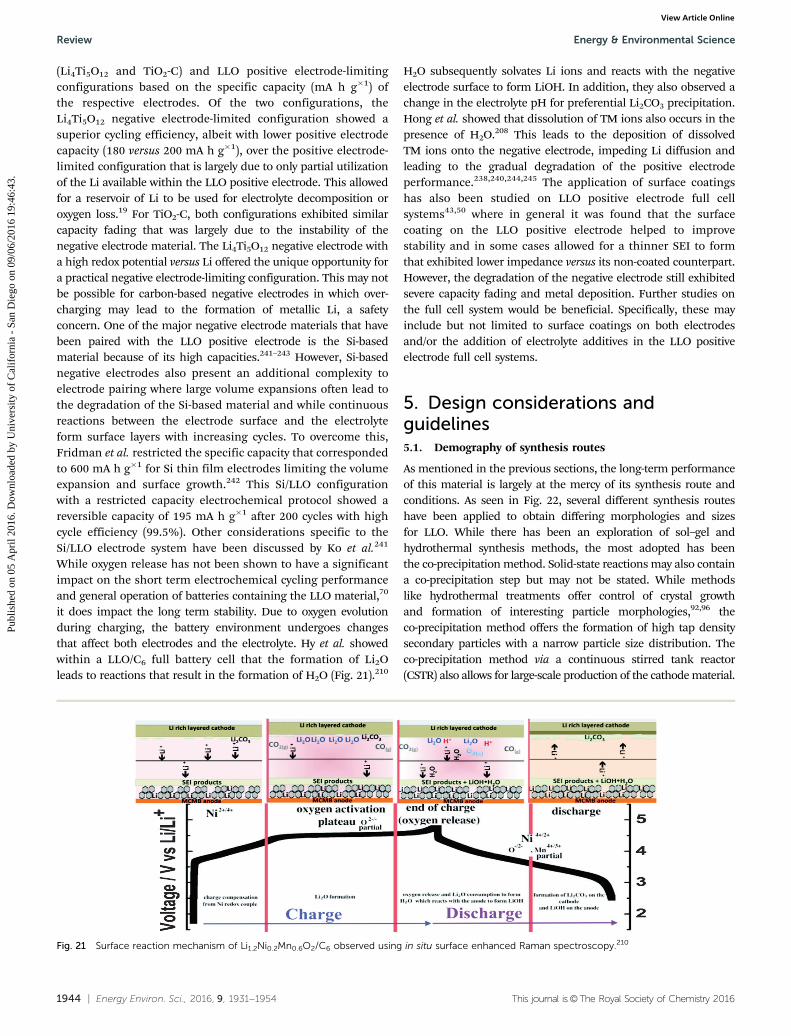
it does impact the long term stability. Due to oxygen evolutionduring charging, the battery environment undergoes changesthat affect both electrodes and the electrolyte. Hy et al. showedwithin a LLO/C6 full battery cell that the formation of Li2Oleads to reactions that result in the formation of H2O (Fig. 21).210
H2O subsequently solvates Li ions and reacts with the negativeelectrode surface to form LiOH. In addition, they also observed achange in the electrolyte pH for preferential Li2CO3 precipitation.Hong et al. showed that dissolution of TM ions also occurs in thepresence of H2O.208 This leads to the deposition of dissolvedTM ions onto the negative electrode, impeding Li diffusion andleading to the gradual degradation of the positive electrodeperformance.238,240,244,245 The application of surface coatingshas also been studied on LLO positive electrode full cellsystems43,50 where in general it was found that the surfacecoating on the LLO positive electrode helped to improvestability and in some cases allowed for a thinner SEI to formthat exhibited lower impedance versus its non-coated counterpart.However, the degradation of the negative electrode still exhibitedsevere capacity fading and metal deposition. Further studies onthe full cell system would be beneficial. Specifically, these mayinclude but not limited to surface coatings on both electrodesand/or the addition of electrolyte additives in the LLO positiveelectrode full cell systems.
5. Design considerations andguidelines5.1. Demography of synthesis routes
As mentioned in the previous sections, the long-term performanceof this material is largely at the mercy of its synthesis route andconditions. As seen in Fig. 22, several different synthesis routeshave been applied to obtain differing morphologies and sizesfor LLO. While there has been an exploration of sol–gel andhydrothermal synthesis methods, the most adopted has beenthe co-precipitation method. Solid-state reactions may also containa co-precipitation step but may not be stated. While methodslike hydrothermal treatments offer control of crystal growthand formation of interesting particle morphologies,92,96 theco-precipitation method offers the formation of high tap densitysecondary particles with a narrow particle size distribution. Theco-precipitation method via a continuous stirred tank reactor(CSTR) also allows for large-scale production of the cathode material.
Fig. 21 Surface reaction mechanism of Li1.2Ni0.2Mn0.6O2/C6 observed using in situ surface enhanced Raman spectroscopy.210
Review Energy & Environmental Science
Publ
ishe
d on
05
Apr
il 20
16. D
ownl
oade
d by
Uni
vers
ity o
f C
alif
orni
a -
San
Die
go o
n 09
/06/
2016
19:
46:4
3.
View Article Online

This journal is©The Royal Society of Chemistry 2016 Energy Environ. Sci., 2016, 9, 1931--1954 | 1945
The next section will describe several factors that have beenexplored using the co-precipitation synthesis route to fabricatethe LLO and discuss several design considerations based on thework of different scientists.
5.2. Co-precipitation and design considerations
Co-precipitation involves salt compounds of desired precursorsthat are dissolved in an aqueous solution and subsequentlyprecipitated or salted out. As illustrated in Fig. 23, the formationof the precursors follows a nucleation stage, followed by growth/agglomeration, and finally an aging process. The resulting pre-cursor’s morphology, composition, density, and size distributionare dependent on the control of different parameters for eachstep.246
For the LLO material, carbonate and hydroxide co-precipitationroutes are among the most popular and well studied forthe LLO precursor that will eventually be lithiated through
high-temperature solid-state reactions. The carbonate routeoffers morphology control and environmental friendlinessrelated to the chemicals involved. However, improper processcontrol may lead to oversized particles and lower tap densitiesdue to void spaces during the growth/agglomeration andaging step. The hydroxide route generally shows a much bettertap density relative to the carbonate route but proves to beproblematic in controlling a homogeneous composition withNi and Mn that are easily oxidized at its nucleation and growth/agglomeration step.247 The co-precipitation of the LLO precursorand the resulting LLO powder is largely contingent on the carefulcontrol of the pH, reaction time, reaction temperature, salt pre-cursor, stirring rate, use of a gas purge, and cooling rate duringhigh-temperature calcination. These parameters and their effect onthe size and density, composition, distribution of metal ions, andmorphology are highlighted in Fig. 24.66,87,108,110,163,180,246–255
5.2.1. Optimization of pH solution. The pH conditions havea large impact on the resulting composition that ultimatelydictates the performance of the final material.249 Wang et al.optimized the pH conditions in the Ni–Mn system for thecarbonate-based co-precipitation using theoretical calculationsbased on equilibrium reactions that may take place within thesystem.163 Fig. 24a shows the residual concentration of the TMin solution as a function of pH where 4 zones are establishedbased on the dominant reactions. Zone 1 (o7.5) shows a largeresidual concentration for Ni and Mn that would result inundesired chemical compositions. Zones 3 (8.5–9.8) and 4(49.8) also result in undesired chemical compositions where ahigh concentration of Ni would occur due to the formationof [Ni(NH3)n]2� complexes and the domination of the hydroxidereaction taking place, respectively. The pH range of 7.5–8.5shows the minimal residual TM concentration that provides thebest conditions to form the desired Ni0.3Mn0.7CO3 precursorwhere they applied a pH value of 8.3. Similarly, the optimalpH conditions for the hydroxide co-precipitation can also bedetermined based on the equilibrium reactions taking place.As seen in the solubility diagrams (Fig. 24b), Nam et al. foundan optimal pH range of 10.5 to 11.5 for Ni–Co–Mn precursorswithin an ammonia-free, citric acid-based co-precipitation route.254
Interestingly, a spherical secondary particle with medium particlesize distribution (76% B13 mm) and high tap density (2.31 g cm�3
vs. 2.6 g cm�3 in commercial LiCoO2) was fabricated using thisroute which may offer a more environmentally friendly route.
5.2.2. Increasing precursor tap density. Under certainconditions, the hydroxide co-precipitation method may beproblematic due to its relative complexity compared to thecarbonate method, especially with high Mn content precursorswhere Mn2+ formed from manganese hydroxide can be easilyoxidized to Mn3+ that would result in a segregated mixedhydroxide.247,249 In addition, primary particles may adopt plate-or needle-like morphologies that may not easily form denselypacked secondary particles. Therefore, in addition to pH,the salt and chelating agent concentration must be carefullycontrolled. Van Bommel and Dahn studied the growth mecha-nism of metal hydroxide particles in the presence of aqueousammonia where they found the tap density of various mixed
Fig. 22 Demography of synthesis routes utilized by years for number ofstudies (top) and percentage of total synthesis in the corresponding year(bottom).
Fig. 23 Schematic representation of the co-precipitation synthesisprocess.
Energy & Environmental Science Review
Publ
ishe
d on
05
Apr
il 20
16. D
ownl
oade
d by
Uni
vers
ity o
f C
alif
orni
a -
San
Die
go o
n 09
/06/
2016
19:
46:4
3.
View Article Online

1946 | Energy Environ. Sci., 2016, 9, 1931--1954 This journal is©The Royal Society of Chemistry 2016
metal hydroxide precursors to be dependent on the reactiontime and pH.249 In particular they observed higher tap densitieswith longer reaction times of over 5 h and at pH values of 11for the Ni(OH)2 precursor and 10.2 for Ni0.5Mn0.5(OH)2 andNi0.333Mn0.333Co0.333(OH)2 (Fig. 24c). They attributed the pHdependence of tap density and particle morphology to theconcentration of metal–ammonia complexes where Ni showscoordination with ammonia over a large pH range of 4–12whereas Mn and Co show coordination over a smaller range of6–10 (Fig. 24d). They proposed a dissolution–crystallizationmechanism where the particle growth is due to the equilibriumbetween the metal hydroxide powders and aqueous ammonia.The presence of aqueous ammonia effectively increases thesolubility of the hydroxide particles based on the followingequilibrium reaction:
TM(OH)2(s) + nNH3 " [TM(NH3)n]2+(aq) + 2OH�
(1)
where the small particles will be consumed in favor of largerparticles to minimize surface free energy.
Wang et al. performed similar studies to control the tap densityand morphology by varying the molar ratio of sodium hydroxideand ammonium hydroxide in the hydroxide co-precipitationroute.247 They found the optimal molar ratio to be 1 : 1 whichresulted in a relatively high tap density (1.5 g cm�3)compared toother molar ratios for the precursor, and spherical secondaryparticles of B10 mm were attributed to the thicker primaryparticles made of multi-layered plates (Fig. 24e). Interestingly,
they found that size distribution was relatively constant followinga two-level agglomeration mechanism regardless of the molarratio. In contrast to the dissolution–crystallization mechanismused to explain the growth of the metal hydroxide particles, theysuggest that the dominant reactions for co-precipitation are thestepwise reactions expressed as
TM2+ + nNH4OH(aq) - [TM(NH3)n]2+(aq) + nH2O(2)
[TM(NH3)n]2+(aq) + 2OH� - TM(OH)2(s) + nNH3
(3)
where the metal ions first complex with ammonia in solutionand then are released to react with hydroxyl groups to formhydroxide precipitates. They showed a higher stability ofthe hydroxide precursor versus the ammonia complex underthe synthesis conditions by observation of no color variations(absence of Ni2+ in solution) of the different synthesis super-natants after 2 h.
5.2.3. Precursor particle size and distribution. Wang et al.found the particle nucleation and growth to follow a linearrelationship with time in the carbonate co-precipitation routeafter an initial decrease in the average particle size.163 Overtime, the particle size distribution decreases and the averageparticle size increases up to 36 mm (Fig. 24f). The larger particlesize, however, may introduce several kinetic limitations duringinitial activation that would result in an increasing capacityover several cycles and limited to only slow current rates.180,253
A specific balance of particle size distribution, tap density,
Fig. 24 (a) Calculated residual transition metal concentration in solution as a function of pH for the carbonate co-precipitation method.163 (b) Solubilitydiagrams of the mixed metal hydroxides for Ni, Mn, and Co.254 (c) The effect of pH on the tap density for different mixed metal-hydroxides.249 (d) Effect ofpH on the concentration of the mixed metal–ammonia complexes in the hydroxide co-precipitation method.249 (e) 1 : 1 molar ratio of sodium andammonium hydroxide leads to spherical secondary particles with thicker primary particles.247 (f) Residence time within the reactor will impact the particlesize and size distribution of the carbonate co-precipitation method.163 (g) The two-level agglomeration in hydroxide co-precipitation.254 (h) Schematicdiagram illustrating the role of gas purging in the formation of mixed metal hydroxides.250
Review Energy & Environmental Science
Publ
ishe
d on
05
Apr
il 20
16. D
ownl
oade
d by
Uni
vers
ity o
f C
alif
orni
a -
San
Die
go o
n 09
/06/
2016
19:
46:4
3.
View Article Online

This journal is©The Royal Society of Chemistry 2016 Energy Environ. Sci., 2016, 9, 1931--1954 | 1947
and particle size will most likely be ideal and extra care maybe needed for carbonate methods where larger particle sizes aregenerally observed compared to hydroxide methods.163,180,247,250
Interestingly, as seen in Fig. 24g, the particle size distribution ofthe LLO particle from the hydroxide co-precipitation has two mainparticle sizes.254 The hydroxide co-precipitation route exhibits atwo-level agglomeration mechanism in which the first agglomera-tion leads to the formation of smaller secondary particles (1–2 mm)followed by a secondary agglomeration which converts the smallersecondary agglomerates to larger secondary particles (10 mm thatare B64–76% of particles).247,254,256
5.2.4. Other considerations. The use of different gasesincluding air, pure O2, CO2, and N2 during co-precipitationcan also affect the structure and morphology of the resultingprecursors.87,250,252 Zhou et al. studied the use of air andN2 purging and its effect on the NixMn1�x mixed hydroxidesamples for different x values using XRD powder patterns andRietveld refinement analysis.250 Fig. 24h shows a schematicrepresentation of the structures synthesized under anaerobicconditions (N2 purge) and in air where slabs represent M(OH)2,cubes represent the Mn3O4 spinel, and circles represent eitherNO3
� or CO32� anions. Under anaerobic conditions, the structure
adopts a more layered structure consistent with the single-phaselayered double hydroxide for x = 1, 5/6, and 0. When synthesizedin air for x = 1, corresponding to Ni(OH)2, Ni cations are moreprone to oxidize to 3+ and anions are incorporated betweenM(OH)2 slabs. For x = 5/6 in air, the structure exhibits misalignedslabs evidenced by poorly formed Bragg peaks, although pure inphase. For x = 1/2 in air, the structure exhibits single M(OH)2
layers that may form due to a two-phase mixture of the M(OH)2
and Mn3O4 spinel in the nanoscale where the inclusion of Mn3O4
disrupts stacking of the M(OH)2 planes. Mn3O4 spinel particlegrowth is found for x = 0 in air that shows up as sharp Braggpeaks. CO2 gas purging has also been used for the carbonatebased co-precipitation method as well.87 In general, the use of gaspurging acts as an additional control for the complex reactionstaking place during co-precipitation where different metalcations are easily oxidized. Other considerations that may betaken into account during the synthesis of the metal precursor isthe stirring speed and temperature, where faster stirring speeds(1000 rpm) and controlled elevated temperatures (50–60 1C) havebeen able to provide homogeneous and consistent reactionswithin the reactor.87,163,247,249,250 A continuous stirred-tank reactor(CSTR) process includes additional factors that must be consid-ered such as feeding rate, reactor volume, chemical reactions andkinetics.163,246 In any case, the use of a CSTR offers a facileapproach for the scale-up of the precursor powders and offers aninteresting design problem for the chemical engineer.
5.2.5. High temperature thermal treatment and morphologycontrol. After the formation of the precursor, the metal precursoris generally mixed with a lithium source (often lithium hydroxideor lithium carbonate) and then subsequently thermally treated athigh temperatures. The first is a pre-heating treatment below500 1C for 3–12 h followed by a high temperature treatmentranging from 600 to 1000 1C for 10–12 h in air or oxygenflow.78,79,84,87,94,188,190,257 Temperatures of r700 1C have been
shown to lead to higher quantities of impurity phases and/orcapacity decay over several cycles.78,79 While several studies haveshown a slightly increasing capacity with increasing hightemperature heat treatment from 800 to 1000 1C, the electro-chemical performance was shown to be similar for short cyclingprotocols.78,79,84,87,257 However, it should be noted that thetemperature would have an effect on the composition for agiven metal system where boundary lines within the phasediagrams will shift with temperature and atmosphere as well asthe cooling rate after heat treatment.190 The phase diagrams forthe Co–Mn,188 Ni–Mn,190 and Ni–Mn–Co258 systems shouldserve as a good starting point for optimizing temperatureselection for high temperature treatment, cooling rates, andatmosphere for a specific composition. The use of combinatorialmethods for studying different compositions within differentmetal systems for quantities that allow for adequate electro-chemical testing would be beneficial to tie the electrochemicalproperties with the material properties.258 There is also certaindegree of control over the morphology during co-precipitationand after high temperature heat treatment which has led topreferred electronic pathways, exposed facets, and other tailoredparticle morphologies.66,108,180,247,256 Chen et al., using ahydroxide co-precipitation synthesis process via a CSTR process,synthesized Li1.2Ni0.2Mn0.6O2 nanoplates with exposed (010)planes that exhibited high rate capabilities of 225 mA h g�1 at1C and up to 150 mA h g�1 of capacity at 20C.108 The nanoplateshave also been observed in other hydroxide co-precipitationprocesses as well by other researchers where the orientationand thickness of the plates are affected by the molar ratio ofsodium and ammonium hydroxide solution.247,256 Oh et al., alsousing the hydroxide co-precipitation via the CSTR process,formed 10 mm secondary particles with submicron-sized flake-shaped primary particles with facile electron migration pathsand then chemically activated with 0.4 wt% of hydrazine for3 h in a 90 1C water bath.180 This material showed good ratecapability and higher average voltage stability over 600 cycles dueto the high surface area, electron pathways of the primaryparticles, and the chemical activation of the Li2MnO3 componentavoiding partial activation.
Fig. 25 is a schematic diagram highlighting some considera-tions that would greatly impact the size and density of theprecursors, composition, distribution of the metal cations, andmorphology. As the reaction time is increased, the size of thesecondary particles increases and particle size distributionnarrows. A balance must be made in order to obtain particlesthat are not too large (o20 mm) to avoid partial activation ofthe material but to keep the size distribution narrow enoughto allow all of the particles to react homogeneously. The tapdensity of the particles is directly related to the solution pH aswell as the molar ratio of sodium and ammonium hydroxide forthe hydroxide method. The composition of a given system willbe determined by the pH of the solution where the ideal pHenvironment can be determined by the equilibrium reactionsof possible products. Ideally, a homogeneous distribution ofmetal cations throughout the entire particle would exhibitsuperior voltage and cycle stability, and careful studies of the
Energy & Environmental Science Review
Publ
ishe
d on
05
Apr
il 20
16. D
ownl
oade
d by
Uni
vers
ity o
f C
alif
orni
a -
San
Die
go o
n 09
/06/
2016
19:
46:4
3.
View Article Online
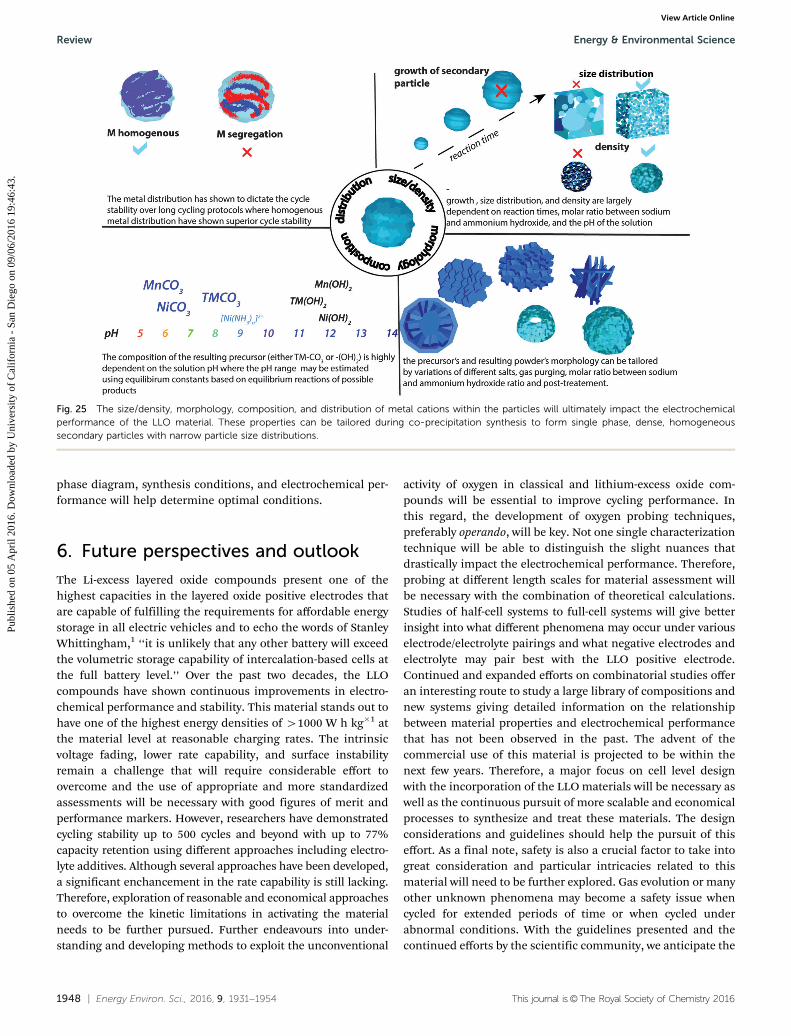
1948 | Energy Environ. Sci., 2016, 9, 1931--1954 This journal is©The Royal Society of Chemistry 2016
phase diagram, synthesis conditions, and electrochemical per-formance will help determine optimal conditions.
6. Future perspectives and outlook
The Li-excess layered oxide compounds present one of thehighest capacities in the layered oxide positive electrodes thatare capable of fulfilling the requirements for affordable energystorage in all electric vehicles and to echo the words of StanleyWhittingham,1 ‘‘it is unlikely that any other battery will exceedthe volumetric storage capability of intercalation-based cells atthe full battery level.’’ Over the past two decades, the LLOcompounds have shown continuous improvements in electro-chemical performance and stability. This material stands out tohave one of the highest energy densities of 41000 W h kg�1 atthe material level at reasonable charging rates. The intrinsicvoltage fading, lower rate capability, and surface instabilityremain a challenge that will require considerable effort toovercome and the use of appropriate and more standardizedassessments will be necessary with good figures of merit andperformance markers. However, researchers have demonstratedcycling stability up to 500 cycles and beyond with up to 77%capacity retention using different approaches including electro-lyte additives. Although several approaches have been developed,a significant enchancement in the rate capability is still lacking.Therefore, exploration of reasonable and economical approachesto overcome the kinetic limitations in activating the materialneeds to be further pursued. Further endeavours into under-standing and developing methods to exploit the unconventional
activity of oxygen in classical and lithium-excess oxide com-pounds will be essential to improve cycling performance. Inthis regard, the development of oxygen probing techniques,preferably operando, will be key. Not one single characterizationtechnique will be able to distinguish the slight nuances thatdrastically impact the electrochemical performance. Therefore,probing at different length scales for material assessment willbe necessary with the combination of theoretical calculations.Studies of half-cell systems to full-cell systems will give betterinsight into what different phenomena may occur under variouselectrode/electrolyte pairings and what negative electrodes andelectrolyte may pair best with the LLO positive electrode.Continued and expanded efforts on combinatorial studies offeran interesting route to study a large library of compositions andnew systems giving detailed information on the relationshipbetween material properties and electrochemical performancethat has not been observed in the past. The advent of thecommercial use of this material is projected to be within thenext few years. Therefore, a major focus on cell level designwith the incorporation of the LLO materials will be necessary aswell as the continuous pursuit of more scalable and economicalprocesses to synthesize and treat these materials. The designconsiderations and guidelines should help the pursuit of thiseffort. As a final note, safety is also a crucial factor to take intogreat consideration and particular intricacies related to thismaterial will need to be further explored. Gas evolution or manyother unknown phenomena may become a safety issue whencycled for extended periods of time or when cycled underabnormal conditions. With the guidelines presented and thecontinued efforts by the scientific community, we anticipate the
Fig. 25 The size/density, morphology, composition, and distribution of metal cations within the particles will ultimately impact the electrochemicalperformance of the LLO material. These properties can be tailored during co-precipitation synthesis to form single phase, dense, homogeneoussecondary particles with narrow particle size distributions.
Review Energy & Environmental Science
Publ
ishe
d on
05
Apr
il 20
16. D
ownl
oade
d by
Uni
vers
ity o
f C
alif
orni
a -
San
Die
go o
n 09
/06/
2016
19:
46:4
3.
View Article Online

This journal is©The Royal Society of Chemistry 2016 Energy Environ. Sci., 2016, 9, 1931--1954 | 1949
LLO material as a cost effective and practical positive electrodematerial for use in the next-generation high energy lithium ionbatteries.
Acknowledgements
UCSD’s efforts are supported by the Assistant Secretary forEnergy Efficiency and Renewable Energy, Office of VehicleTechnologies of the U.S. DOE under Contract No. DE-AC02-05CH11231, Subcontract No. 7073923, under the AdvancedBattery Materials Research (BMR) program (formerly knownas BATT). We would like to also acknowledge Devin Cela for hisfruitful discussions and input.
References
1 M. S. Whittingham, Chem. Rev., 2014, 114, 11414–11443.2 M. S. Whittingham, Chem. Rev., 2004, 104, 4271–4301.3 B. Nykvist and M. Nilsson, Nat. Clim. Change, 2015, 5,
329–332.4 DOE Annual Merit Review 2015, http://www.annualmeritre
view.energy.gov/.5 T. Ohzuku, M. Nagayama, K. Tsuji and K. Ariyoshi, J. Mater.
Chem., 2011, 21, 10179.6 M. H. Rossouw and M. M. Thackeray, Mater. Res. Bull.,
1991, 26, 463–473.7 K. Naoi, D. Yonekura, S. Moriyama, H. Goto, E. Iwama,
S. Kubota, S. Ishimoto and W. Naoi, J. Alloys Compd., 2014,605, 137–141.
8 J. Kim, Solid State Ionics, 2003, 164, 43–49.9 S. H. Kang and K. Amine, J. Power Sources, 2005, 146,
654–657.10 L. Zhang, K. Takada, N. Ohta, K. Fukuda, M. Osada,
L. Wang, T. Sasaki and M. Watanabe, J. Electrochem. Soc.,2005, 152, A171.
11 L. Zhang, K. Takada, N. Ohta, K. Fukuda and T. Sasaki,J. Power Sources, 2005, 146, 598–601.
12 N. Tran, L. Croguennec, C. Labrugere, C. Jordy, P. Biensanand C. Delmas, J. Electrochem. Soc., 2006, 153, A261.
13 A. Ito, D. Li, Y. Ohsawa and Y. Sato, J. Power Sources, 2008,183, 344–346.
14 Y. Wu, A. Vadivel Murugan and A. Manthiram,J. Electrochem. Soc., 2008, 155, A635.
15 J. Gao and A. Manthiram, J. Power Sources, 2009, 191,644–647.
16 S.-H. Kang and M. M. Thackeray, Electrochem. Commun.,2009, 11, 748–751.
17 Q. Y. Wang, J. Liu, A. V. Murugan and A. Manthiram,J. Mater. Chem., 2009, 19, 4965.
18 A. Ito, D. Li, Y. Sato, M. Arao, M. Watanabe, M. Hatano,H. Horie and Y. Ohsawa, J. Power Sources, 2010, 195,567–573.
19 S. H. Kang, V. G. Pol, I. Belharouak and M. M. Thackeray,J. Electrochem. Soc., 2010, 157, A267.
20 J. Liu and A. Manthiram, J. Mater. Chem., 2010, 20, 3961.
21 J. Liu, Q. Wang, B. Reeja-Jayan and A. Manthiram, Electrochem.Commun., 2010, 12, 750–753.
22 A. Abouimrane, O. C. Compton, H. Deng, I. Belharouak,D. A. Dikin, S. T. Nguyen and K. Amine, Electrochem. Solid-State Lett., 2011, 14, A126.
23 K. G. Gallagher, S.-H. Kang, S. U. Park and S. Y. Han,J. Power Sources, 2011, 196, 9702–9707.
24 V. A. Godbole, J.-F. o. Colin and P. Novak, J. Electrochem.Soc., 2011, 158, A1005.
25 A. Ito, Y. Sato, T. Sanada, M. Hatano, H. Horie andY. Ohsawa, J. Power Sources, 2011, 196, 6828–6834.
26 A. Ito, K. Shoda, Y. Sato, M. Hatano, H. Horie andY. Ohsawa, J. Power Sources, 2011, 196, 4785–4790.
27 E. S. Lee and A. Manthiram, J. Electrochem. Soc., 2011,158, A47.
28 H. Liu and L. Tan, Mater. Chem. Phys., 2011, 129, 729–732.29 J.-L. Liu, J. Wang and Y.-Y. Xia, Electrochim. Acta, 2011, 56,
7392–7396.30 Y. Seok Jung, A. S. Cavanagh, Y. Yan, S. M. George and
A. Manthiram, J. Electrochem. Soc., 2011, 158, A1298.31 W. C. West, J. Soler, M. C. Smart, B. V. Ratnakumar,
S. Firdosy, V. Ravi, M. S. Anderson, J. Hrbacek, E. S. Leeand A. Manthiram, J. Electrochem. Soc., 2011, 158, A883.
32 N. Yabuuchi, K. Yoshii, S. T. Myung, I. Nakai andS. Komaba, J. Am. Chem. Soc., 2011, 133, 4404–4419.
33 F. Amalraj, M. Talianker, B. Markovsky, D. Sharon,L. Burlaka, G. Shafir, E. Zinigrad, O. Haik, D. Aurbach,J. Lampert, M. Schulz-Dobrick and A. Garsuch,J. Electrochem. Soc., 2012, 160, A324–A337.
34 C. Ghanty, R. N. Basu and S. B. Majumder, J. Electrochem.Soc., 2012, 159, A1125–A1134.
35 M. Gu, I. Belharouak, A. Genc, Z. Wang, D. Wang,K. Amine, F. Gao, G. Zhou, S. Thevuthasan, D. R. Baer,J. G. Zhang, N. D. Browning, J. Liu and C. Wang, Nano Lett.,2012, 12, 5186–5191.
36 W. He, J. Qian, Y. Cao, X. Ai and H. Yang, RSC Adv., 2012,2, 3423.
37 E.-S. Lee, A. Huq, H.-Y. Chang and A. Manthiram, Chem.Mater., 2012, 24, 600–612.
38 J. Liu, L. Chen, M. Hou, F. Wang, R. Che and Y. Xia,J. Mater. Chem., 2012, 22, 25380.
39 S. K. Martha, J. Nanda, G. M. Veith and N. J. Dudney,J. Power Sources, 2012, 216, 179–186.
40 Y.-K. Sun, M.-J. Lee, C. S. Yoon, J. Hassoun, K. Amine andB. Scrosati, Adv. Mater., 2012, 24, 1192–1196.
41 Q. Wu, W. Lu, M. Miranda, T. K. Honaker-Schroeder,K. Y. Lakhsassi and D. Dees, Electrochem. Commun.,2012, 24, 78–81.
42 H. Yu, H. Kim, Y. Wang, P. He, D. Asakura, Y. Nakamuraand H. Zhou, Phys. Chem. Chem. Phys., 2012, 14,6584–6595.
43 M. Bettge, Y. Li, B. Sankaran, N. D. Rago, T. Spila,R. T. Haasch, I. Petrov and D. P. Abraham, J. Power Sources,2013, 233, 346–357.
44 S. K. Martha, J. Nanda, Y. Kim, R. R. Unocic, S. Pannalaand N. J. Dudney, J. Mater. Chem. A, 2013, 1, 5587.
Energy & Environmental Science Review
Publ
ishe
d on
05
Apr
il 20
16. D
ownl
oade
d by
Uni
vers
ity o
f C
alif
orni
a -
San
Die
go o
n 09
/06/
2016
19:
46:4
3.
View Article Online
1950 | Energy Environ. Sci., 2016, 9, 1931--1954 This journal is©The Royal Society of Chemistry 2016
45 S. J. Shi, J. P. Tu, Y. Y. Tang, Y. X. Yu, Y. Q. Zhang andX. L. Wang, J. Power Sources, 2013, 221, 300–307.
46 S. J. Shi, J. P. Tu, Y. Y. Tang, Y. X. Yu, Y. Q. Zhang,X. L. Wang and C. D. Gu, J. Power Sources, 2013, 228, 14–23.
47 S. J. Shi, J. P. Tu, Y. J. Zhang, Y. D. Zhang, X. Y. Zhao,X. L. Wang and C. D. Gu, Electrochim. Acta, 2013, 108,441–448.
48 B. Song, H. Liu, Z. Liu, P. Xiao, M. O. Lai and L. Lu, Sci.Rep., 2013, 3, 3094.
49 O. Toprakci, H. A. K. Toprakci, Y. Li, L. Ji, L. Xue, H. Lee,S. Zhang and X. Zhang, J. Power Sources, 2013, 241,522–528.
50 X. Zhang, I. Belharouak, L. Li, Y. Lei, J. W. Elam, A. Nie,X. Chen, R. S. Yassar and R. L. Axelbaum, Adv. EnergyMater., 2013, 3, 1299–1307.
51 J. Zheng, S. Deng, Z. Shi, H. Xu, H. Xu, Y. Deng, Z. Zhangand G. Chen, J. Power Sources, 2013, 221, 108–113.
52 Y. Chen, K. Xie, C. Zheng, Z. Ma and Z. Chen, ACS Appl.Mater. Interfaces, 2014, 6, 16888–16894.
53 M. Choi, G. Ham, B.-S. Jin, S.-M. Lee, Y. M. Lee, G. Wangand H.-S. Kim, J. Alloys Compd., 2014, 608, 110–117.
54 W. Choi, A. Benayard, J.-H. Park, J. Park, S.-G. Doo andJ. Mun, Electrochim. Acta, 2014, 117, 492–497.
55 F. Fu, Y.-P. Deng, C.-H. Shen, G.-L. Xu, X.-X. Peng,Q. Wang, Y.-F. Xu, J.-C. Fang, L. Huang and S.-G. Sun,Electrochem. Commun., 2014, 44, 54–58.
56 S. Guo, H. Yu, P. Liu, X. Liu, D. Li, M. Chen, M. Ishida andH. Zhou, J. Mater. Chem. A, 2014, 2, 4422.
57 S. Han, B. Qiu, Z. Wei, Y. Xia and Z. Liu, J. Power Sources,2014, 268, 683–691.
58 L. Li, Y. L. Chang, H. Xia, B. H. Song, J. R. Yang, K. S. Leeand L. Lu, Solid State Ionics, 2014, 264, 36–44.
59 Q. Li, G. Li, C. Fu, D. Luo, J. Fan and L. Li, ACS Appl. Mater.Interfaces, 2014, 6, 10330–10341.
60 H. Liu, C. Du, G. Yin, B. Song, P. Zuo, X. Cheng, Y. Ma andY. Gao, J. Mater. Chem. A, 2014, 2, 15640.
61 J. Liu, M. Hou, J. Yi, S. Guo, C. Wang and Y. Xia, EnergyEnviron. Sci., 2014, 7, 705–714.
62 X. Miao, Y. Yan, C. Wang, L. Cui, J. Fang and G. Yang,J. Power Sources, 2014, 247, 219–227.
63 P. Oh, M. Ko, S. Myeong, Y. Kim and J. Cho, Adv. EnergyMater., 2014, 4, 1470084.
64 E. O. Ortiz-Quiles, J. Soler, M. Gobet, T. Nosach,O. J. Garcıa-Ricard, O. Resto, A. J. Hernandez-Maldonado,S. Greenbaum, W. C. West and C. R. Cabrera, RSC Adv.,2014, 4, 12018.
65 B. Qiu, J. Wang, Y. Xia, Z. Wei, S. Han and Z. Liu, ACS Appl.Mater. Interfaces, 2014, 6, 9185–9193.
66 P. Remith and N. Kalaiselvi, Nanoscale, 2014, 6,14724–14732.
67 F. Wu, Z. Wang, Y. Su, N. Yan, L. Bao and S. Chen, J. PowerSources, 2014, 247, 20–25.
68 J. Zhang, J. Wang, J. Yang and Y. NuLi, Electrochim. Acta,2014, 117, 99–104.
69 L. Guo, N. Zhao, J. Li, C. He, C. Shi and E. Liu, ACS Appl.Mater. Interfaces, 2015, 7, 391–399.
70 J. Jiang and J. R. Dahn, Electrochim. Acta, 2006, 51,3413–3416.
71 J. Li, J. Camardese, R. Shunmugasundaram, S. Glazier,Z. Lu and J. R. Dahn, Chem. Mater., 2015, 27, 3366–3377.
72 X. He, J. Wang, R. Kloepsch, S. Krueger, H. Jia, H. Liu,B. Vortmann and J. Li, Nano Res., 2014, 7, 110–118.
73 A. D. Robertson and P. G. Bruce, Chem. Commun., 2002,2790–2791.
74 D. Y. W. Yu, K. Yanagida and H. Nakamura, J. Electrochem.Soc., 2010, 157, A1177.
75 D. Y. W. Yu and K. Yanagida, J. Electrochem. Soc., 2011,158, A1015.
76 S. Francis Amalraj, B. Markovsky, D. Sharon, M. Talianker,E. Zinigrad, R. Persky, O. Haik, J. Grinblat, J. Lampert,M. Schulz-Dobrick, A. Garsuch, L. Burlaka and D. Aurbach,Electrochim. Acta, 2012, 78, 32–39.
77 S. F. Amalraj, D. Sharon, M. Talianker, C. M. Julien,L. Burlaka, R. Lavi, E. Zhecheva, B. Markovsky, E. Zinigrad,D. Kovacheva, R. Stoyanova and D. Aurbach, Electrochim.Acta, 2013, 97, 259–270.
78 Z. Lu, D. D. MacNeil and J. R. Dahn, Electrochem. Solid-State Lett., 2001, 4, A191.
79 Z. Lu, L. Y. Beaulieu, R. A. Donaberger, C. L. Thomas andJ. R. Dahn, J. Electrochem. Soc., 2002, 149, A778.
80 Z. Lu and J. R. Dahn, J. Electrochem. Soc., 2002, 149, A815.81 J. H. Kim and Y. K. Sun, J. Power Sources, 2003, 119–121,
166–170.82 C. S. Johnson, J. S. Kim, C. Lefief, N. Li, J. T. Vaughey and
M. M. Thackeray, Electrochem. Commun., 2004, 6, 1085–1091.83 D. A. R. Barkhouse and J. R. Dahn, J. Electrochem. Soc.,
2005, 152, A746.84 B. J. Hwang, C. J. Wang, C. H. Chen, Y. W. Tsai and
M. Venkateswarlu, J. Power Sources, 2005, 146, 658–663.85 Y. J. Kang, J. H. Kim, S. W. Lee and Y. K. Sun, Electrochim.
Acta, 2005, 50, 4784–4791.86 A. R. Armstrong, M. Holzapfel, P. Novak, C. S. Johnson,
S. H. Kang, M. M. Thackeray and P. G. Bruce, J. Am. Chem.Soc., 2006, 128, 8694–8698.
87 D. K. Lee, S. H. Park, K. Amine, H. J. Bang, J. Parakash andY. K. Sun, J. Power Sources, 2006, 162, 1346–1350.
88 M. M. Thackeray, S. H. Kang, C. S. Johnson, J. T. Vaughey andS. A. Hackney, Electrochem. Commun., 2006, 8, 1531–1538.
89 C. S. Johnson, N. Li, C. Lefief and M. M. Thackeray,Electrochem. Commun., 2007, 9, 787–795.
90 C. H. Lei, J. Bareno, J. G. Wen, I. Petrov, S. H. Kang andD. P. Abraham, J. Power Sources, 2008, 178, 422–433.
91 M. Jiang, B. Key, Y. S. Meng and C. P. Grey, Chem. Mater.,2009, 21, 2733–2745.
92 M. G. Kim, M. Jo, Y. S. Hong and J. Cho, Chem. Commun.,2009, 218–220.
93 F. Wu, H. Lu, Y. Su, N. Li, L. Bao and S. Chen, J. Appl.Electrochem., 2009, 40, 783–789.
94 C. R. Fell, K. J. Carroll, M. Chi and Y. S. Meng,J. Electrochem. Soc., 2010, 157, A1202.
95 J. Hong, D.-H. Seo, S.-W. Kim, H. Gwon, S.-T. Oh andK. Kang, J. Mater. Chem., 2010, 20, 10179.
Review Energy & Environmental Science
Publ
ishe
d on
05
Apr
il 20
16. D
ownl
oade
d by
Uni
vers
ity o
f C
alif
orni
a -
San
Die
go o
n 09
/06/
2016
19:
46:4
3.
View Article Online

This journal is©The Royal Society of Chemistry 2016 Energy Environ. Sci., 2016, 9, 1931--1954 | 1951
96 G. Z. Wei, X. Lu, F. S. Ke, L. Huang, J. T. Li, Z. X. Wang,Z. Y. Zhou and S. G. Sun, Adv. Mater., 2010, 22, 4364–4367.
97 A. van Bommel, L. J. Krause and J. R. Dahn, J. Electrochem.Soc., 2011, 158, A731.
98 B. Xu, C. R. Fell, M. Chi and Y. S. Meng, Energy Environ.Sci., 2011, 4, 2223.
99 S. Hy, W.-N. Su, J.-M. Chen and B.-J. Hwang, J. Phys. Chem. C,2012, 116, 25242–25247.
100 Y. Jiang, Z. Yang, W. Luo, X.-L. Hu, W.-X. Zhang andY.-H. Huang, J. Mater. Chem., 2012, 22, 14964.
101 D. Wang, I. Belharouak, S. Gallagher, G. Zhou andK. Amine, J. Mater. Chem., 2012, 22, 12039.
102 H. Z. Zhang, Q. Q. Qiao, G. R. Li, S. H. Ye and X. P. Gao,J. Mater. Chem., 2012, 22, 13104.
103 J. H. Kim, S. H. Choi, M. Y. Son, M. H. Kim, J.-K. Lee andY. C. Kang, Ceram. Int., 2013, 39, 331–336.
104 H. J. Lee and Y. J. Park, J. Power Sources, 2013, 244,222–233.
105 F. Wu, N. Li, Y. Su, H. Shou, L. Bao, W. Yang, L. Zhang,R. An and S. Chen, Adv. Mater., 2013, 25, 3722–3726.
106 L. Zhang, B. Wu, N. Li, D. Mu, C. Zhang and F. Wu, J. PowerSources, 2013, 240, 644–652.
107 J. Zheng, M. Gu, J. Xiao, P. Zuo, C. Wang and J. G. Zhang,Nano Lett., 2013, 13, 3824–3830.
108 L. Chen, Y. Su, S. Chen, N. Li, L. Bao, W. Li, Z. Wang,M. Wang and F. Wu, Adv. Mater., 2014, 26, 6756–6760.
109 H. J. Lee and Y. J. Park, Mater. Res. Bull., 2014, 58, 169–173.110 L. Li, S. Song, X. Zhang, R. Chen, J. Lu, F. Wu and
K. Amine, J. Power Sources, 2014, 272, 922–928.111 F. Wu, N. Li, Y. Su, L. Zhang, L. Bao, J. Wang, L. Chen,
Y. Zheng, L. Dai, J. Peng and S. Chen, Nano Lett., 2014, 14,3550–3555.
112 J. Zheng, M. Gu, A. Genc, J. Xiao, P. Xu, X. Chen, Z. Zhu,W. Zhao, L. Pullan, C. Wang and J. G. Zhang, Nano Lett.,2014, 14, 2628–2635.
113 D. Kim, S.-H. Kang, M. Balasubramanian and C. S.Johnson, Electrochem. Commun., 2010, 12, 1618–1621.
114 B. Ammundsen, J. Paulsen, I. Davidson, R.-S. Liu, C.-H.Shen, J.-M. Chen, L.-Y. Jang and J.-F. Lee, J. Electrochem.Soc., 2002, 149, A431.
115 M. Balasubramanian, J. McBreen, I. J. Davidson, P. S.Whitfield and I. Kargina, J. Electrochem. Soc., 2002,149, A176.
116 Z. Lu and J. R. Dahn, J. Electrochem. Soc., 2002, 149, A1454.117 Z. Lu and J. R. Dahn, J. Electrochem. Soc., 2002, 149,
A1454–A1459.118 X. Wu, Solid State Ionics, 2004, 169, 145–150.119 X. Wu, K. S. Ryu, Y.-S. Hong, Y. J. Park and S. H. Chang,
J. Power Sources, 2004, 132, 219–224.120 I. R. Mangani, C. W. Park, Y. K. Yoon, J. H. Beom and
J. Kim, J. Electrochem. Soc., 2007, 154, A359.121 N. Yabuuchi, K. Yamamoto, K. Yoshii, I. Nakai, T. Nishizawa,
A. Omaru, T. Toyooka and S. Komaba, J. Electrochem. Soc.,2012, 160, A39–A45.
122 J. Lee, A. Urban, X. Li, D. Su, G. Hautier and G. Ceder,Science, 2014, 343, 519–522.
123 B. Song, C. Zhou, H. Wang, H. Liu, Z. Liu, M. O. Lai andL. Lu, J. Electrochem. Soc., 2014, 161, A1723–A1730.
124 T. Zhao, L. Li, S. Chen, R. Chen, X. Zhang, J. Lu, F. Wu andK. Amine, J. Power Sources, 2014, 245, 898–907.
125 J. Kikkawa, T. Akita, M. Tabuchi, M. Shikano, K. Tatsumiand M. Kohyama, Appl. Phys. Lett., 2007, 91, 054103.
126 M. Tabuchi, Y. Nabeshima, K. Ado, M. Shikano, H. Kageyamaand K. Tatsumi, J. Power Sources, 2007, 174, 554–559.
127 M. Tabuchi, Y. Nabeshima, T. Takeuchi, H. Kageyama,K. Tatsumi, J. Akimoto, H. Shibuya and J. Imaizumi,J. Power Sources, 2011, 196, 3611–3622.
128 K. Karthikeyan, S. Amaresh, G. W. Lee, V. Aravindan,H. Kim, K. S. Kang, W. S. Kim and Y. S. Lee, Electrochim.Acta, 2012, 68, 246–253.
129 F. Lian, M. Gao, W. H. Qiu, P. Axmann and M. Wohlfahrt-Mehrens, J. Appl. Electrochem., 2012, 42, 409–417.
130 K. Karthikeyan, S. Amaresh, S. H. Kim, V. Aravindan andY. S. Lee, Electrochim. Acta, 2013, 108, 749–756.
131 J. Li, L. Wang, L. Wang, J. Luo, J. Gao, J. Li, J. Wang, X. He,G. Tian and S. Fan, J. Power Sources, 2013, 244, 652–657.
132 G.-B. Liu, H. Liu, Y. Wang, Y.-F. Shi and Y. Zhang, J. SolidState Electrochem., 2013, 17, 2437–2444.
133 G. B. Liu, H. Liu and Y. F. Shi, Electrochim. Acta, 2013, 88,112–116.
134 T. Zhao, S. Chen, L. Li, X. Zhang, H. Wu, T. Wu, C. J. Sun,R. Chen, F. Wu, J. Lu and K. Amine, ACS Appl. Mater.Interfaces, 2014, 6, 22305–22315.
135 Y. Zhao, Y. Sun, Y. Yue, X. Hu and M. Xia, Electrochim. Acta,2014, 130, 66–75.
136 J. R. Croy, M. Balasubramanian, D. Kim, S.-H. Kang andM. M. Thackeray, Chem. Mater., 2011, 23, 5415–5424.
137 F. L. Liu, S. Zhang, C. Deng, Q. Wu, M. Zhang, F. L. Meng,H. Gao and Y. H. Sun, J. Electrochem. Soc., 2012, 159,A1591–A1597.
138 K. Ozawa, Y. Nakao, T. Mochiku, Z. Cheng, L. Wang,H. Iwai, Y. Tsuchiya, H. Fujii and N. Igawa, J. Electrochem.Soc., 2012, 159, A300–A304.
139 D. Luo, G. Li, X. Guan, C. Yu, J. Zheng, X. Zhang and L. Li,J. Mater. Chem. A, 2013, 1, 1220–1227.
140 D. Ye, B. Wang, Y. Chen, G. Han, Z. Zhang, D. Hulicova-Jurcakova, J. Zou and L. Wang, J. Mater. Chem. A, 2014, 2,18767–18774.
141 C. W. Park, S. H. Kim, K. S. Nahm, H. T. Chung, Y. S. Lee,J. H. Lee, S. Boo and J. Kim, J. Alloys Compd., 2008, 449,343–348.
142 W. Liu, P. Oh, X. Liu, S. Myeong, W. Cho and J. Cho,Adv. Energy Mater., 2015, 5, 1500274.
143 W. Tang, H. Kanoh, X. Yang and K. Ooi, Chem. Mater.,2000, 12, 3271–3279.
144 Y. K. Sun, M. G. Kim, S. H. Kang and K. Amine, J. Mater.Chem., 2003, 13, 319–322.
145 S. Sivaprakash, S. B. Majumder and R. S. Katiyar,J. Electrochem. Soc., 2009, 156, A328.
146 C. S. Johnson, S. H. Kang, J. T. Vaughey, S. V. Pol,M. Balasubramanian and M. M. Thackeray, Chem. Mater.,2010, 22, 1263–1270.
Energy & Environmental Science Review
Publ
ishe
d on
05
Apr
il 20
16. D
ownl
oade
d by
Uni
vers
ity o
f C
alif
orni
a -
San
Die
go o
n 09
/06/
2016
19:
46:4
3.
View Article Online

1952 | Energy Environ. Sci., 2016, 9, 1931--1954 This journal is©The Royal Society of Chemistry 2016
147 S. Sivaprakash and S. B. Majumder, Solid State Ionics, 2010,181, 730–739.
148 D. Kim, G. Sandi, J. R. Croy, K. G. Gallagher, S. H. Kang,E. Lee, M. D. Slater, C. S. Johnson and M. M. Thackeray,J. Electrochem. Soc., 2012, 160, A31–A38.
149 M. Sathiya, K. Ramesha, G. Rousse, D. Foix, D. Gonbeau,K. Guruprakash, A. S. Prakash, M. L. Doublet and J. M.Tarascon, Chem. Commun., 2013, 49, 11376–11378.
150 M. Sathiya, K. Ramesha, G. Rousse, D. Foix, D. Gonbeau,A. S. Prakash, M. L. Doublet, K. Hemalatha and J. M.Tarascon, Chem. Mater., 2013, 25, 1121–1131.
151 M. Sathiya, G. Rousse, K. Ramesha, C. P. Laisa, H. Vezin,M. T. Sougrati, M. L. Doublet, D. Foix, D. Gonbeau,W. Walker, A. S. Prakash, M. Ben Hassine, L. Dupontand J. M. Tarascon, Nat. Mater., 2013, 12, 827–835.
152 M. Tabuchi, Y. Nabeshima, T. Takeuchi, H. Kageyama,J. Imaizumi, H. Shibuya and J. Akimoto, J. Power Sources,2013, 221, 427–434.
153 J. Ma, Y. Gao, Z. Wang and L. Chen, J. Power Sources, 2014,258, 314–320.
154 W. Zhao, S. Harada, Y. Furuya, S. Yamamoto and H. Noguchi,J. Power Sources, 2014, 261, 324–331.
155 Y. Gao, X. Wang, J. Ma, Z. Wang and L. Chen, Chem. Mater.,2015, 27, 3456–3461.
156 A. K. Kalathil, P. Arunkumar, H. Kim da, J. W. Lee andW. B. Im, ACS Appl. Mater. Interfaces, 2015, 7, 7118–7128.
157 E. McCalla, A. M. Abakumov, M. Saubanere, D. Foix,E. J. Berg, G. Rousse, M.-L. Doublet, D. Gonbeau, P. Novak,G. Van Tendeloo, R. Dominko and J.-M. Tarascon, Science,2015, 350, 1516–1521.
158 M. Sathiya, A. M. Abakumov, D. Foix, G. Rousse, K. Ramesha,M. Saubanere, M. L. Doublet, H. Vezin, C. P. Laisa, A. S.Prakash, D. Gonbeau, G. VanTendeloo and J. M. Tarascon,Nat. Mater., 2015, 14, 230–238.
159 L. Ghadbeigi, J. K. Harada, B. R. Lettiere and T. D. Sparks,Energy Environ. Sci., 2015, 8, 1640–1650.
160 M. Kunduraci and G. G. Amatucci, Electrochim. Acta, 2008,53, 4193–4199.
161 X. Yan, G. Yang, J. Liu, Y. Ge, H. Xie, X. Pan and R. Wang,Electrochim. Acta, 2009, 54, 5770–5774.
162 D. Andre, S.-J. Kim, P. Lamp, S. F. Lux, F. Maglia, O. Paschosand B. Stiaszny, J. Mater. Chem. A, 2015, 3, 6709–6732.
163 D. Wang, I. Belharouak, G. M. Koenig, G. Zhou andK. Amine, J. Mater. Chem., 2011, 21, 9290.
164 Y. K. Sun, M. J. Lee, C. S. Yoon, J. Hassoun, K. Amine andB. Scrosati, Adv. Mater., 2012, 24, 1192–1196.
165 S. H. Kang and M. M. Thackeray, J. Electrochem. Soc., 2008,155, A269.
166 M. M. Thackeray, C. S. Johnson, J. T. Vaughey, N. Li andS. A. Hackney, J. Mater. Chem., 2005, 15, 2257.
167 A. R. Armstrong, M. Holzapfel, P. Novak, C. S. Johnson,S. H. Kang, M. M. Thackeray and P. G. Bruce, J. Am. Chem.Soc., 2006, 128, 8694.
168 J. Bareno, M. Balasubramanian, S. H. Kang, J. G. Wen,C. H. Lei, S. V. Pol, I. Petrov and D. P. Abraham, Chem.Mater., 2011, 23, 2039–2050.
169 P. J. Phillips, J. Bareno, Y. Li, D. P. Abraham and R. F. Klie,Adv. Energy Mater., 2015, 5, 1501252.
170 J. R. Croy, D. Kim, M. Balasubramanian, K. Gallagher,S.-H. Kang and M. M. Thackeray, J. Electrochem. Soc., 2012,159, A781.
171 J. R. Croy, M. Balasubramanian, K. G. Gallagher andA. K. Burrell, Acc. Chem. Res., 2015, 48, 2813–2821.
172 Y. Li, J. Bareno, M. Bettge and D. P. Abraham,J. Electrochem. Soc., 2014, 162, A155–A161.
173 F. Dogan, B. R. Long, J. R. Croy, K. G. Gallagher, H. Iddir,J. T. Russell, M. Balasubramanian and B. Key, J. Am. Chem.Soc., 2015, 137, 2328–2335.
174 J. R. Croy, K. G. Gallagher, M. Balasubramanian, B. R. Longand M. M. Thackeray, J. Electrochem. Soc., 2014, 161,A318–A325.
175 D. Kim, J. R. Croy and M. M. Thackeray, Electrochem.Commun., 2013, 36, 103–106.
176 K. G. Gallagher, J. R. Croy, M. Balasubramanian, M. Bettge,D. P. Abraham, A. K. Burrell and M. M. Thackeray,Electrochem. Commun., 2013, 33, 96–98.
177 M. Bettge, Y. Li, K. Gallagher, Y. Zhu, Q. Wu, W. Lu,I. Bloom and D. P. Abraham, J. Electrochem. Soc., 2013,160, A2046–A2055.
178 S. LeVine, The Powerhouse: Inside the Invention of a Batteryto Save the World, Viking, New York, 2015.
179 J. Zheng, J. Xiao, M. Gu, P. Zuo, C. Wang and J.-G. Zhang,J. Power Sources, 2014, 250, 313–318.
180 P. Oh, S. Myeong, W. Cho, M. J. Lee, M. Ko, H. Y. Jeong andJ. Cho, Nano Lett., 2014, 14, 5965–5972.
181 S. Meng, G. Ceder, C. P. Grey, W.-S. Yoon, M. Jiang,J. Breger and Y. Shao-Horn, Chem. Mater., 2005, 17, 2386.
182 M. M. Thackeray, S.-H. Kang, C. S. Johnson, J. T. Vaughey,R. Benedek and S. A. Hackney, J. Mater. Chem., 2007, 17, 3112.
183 J. Bareno, C. H. Lei, J. G. Wen, S. H. Kang, I. Petrov andD. P. Abraham, Adv. Mater., 2010, 22, 1122–1127.
184 K. A. Jarvis, Z. Deng, L. F. Allard, A. Manthiram andP. J. Ferreira, Chem. Mater., 2011, 23, 3614–3621.
185 H. Yu, R. Ishikawa, Y. G. So, N. Shibata, T. Kudo, H. Zhouand Y. Ikuhara, Angew. Chem., Int. Ed., 2013, 52,5969–5973.
186 A. Devaraj, M. Gu, R. Colby, P. Yan, C. M. Wang,J. M. Zheng, J. Xiao, A. Genc, J. G. Zhang, I. Belharouak,D. Wang, K. Amine and S. Thevuthasan, Nat. Commun.,2015, 6, 8014.
187 A. K. Shukla, Q. M. Ramasse, C. Ophus, H. Duncan,F. Hage and G. Chen, Nat. Commun., 2015, 6, 8711.
188 E. McCalla, C. M. Lowartz, C. R. Brown and J. R. Dahn,Chem. Mater., 2013, 25, 912–918.
189 E. McCalla, A. W. Rowe, J. Camardese and J. R. Dahn,Chem. Mater., 2013, 25, 2716–2721.
190 E. McCalla, A. W. Rowe, R. Shunmugasundaram andJ. R. Dahn, Chem. Mater., 2013, 25, 989–999.
191 C. R. Brown, E. McCalla, C. Watson and J. R. Dahn,ACS Comb. Sci., 2015, 17, 381–391.
192 R. Shunmugasundaram, R. Senthil Arumugam andJ. R. Dahn, Chem. Mater., 2015, 27, 757–767.
Review Energy & Environmental Science
Publ
ishe
d on
05
Apr
il 20
16. D
ownl
oade
d by
Uni
vers
ity o
f C
alif
orni
a -
San
Die
go o
n 09
/06/
2016
19:
46:4
3.
View Article Online

This journal is©The Royal Society of Chemistry 2016 Energy Environ. Sci., 2016, 9, 1931--1954 | 1953
193 M. Gu, A. Genc, I. Belharouak, D. Wang, K. Amine,S. Thevuthasan, D. R. Baer, J.-G. Zhang, N. D. Browning,J. Liu and C. Wang, Chem. Mater., 2013, 25, 2319–2326.
194 E. McCalla, A. S. Prakash, E. Berg, M. Saubanere,A. M. Abakumov, D. Foix, B. Klobes, M. T. Sougrati,G. Rousse, F. Lepoivre, S. Mariyappan, M. L. Doublet,D. Gonbeau, P. Novak, G. Van Tendeloo, R. P. Hermannand J. M. Tarascon, J. Electrochem. Soc., 2015, 162,A1341–A1351.
195 E. McCalla, M. T. Sougrati, G. Rousse, E. J. Berg,A. Abakumov, N. Recham, K. Ramesha, M. Sathiya,R. Dominko, G. Van Tendeloo, P. Novak and J. M.Tarascon, J. Am. Chem. Soc., 2015, 137, 4804–4814.
196 R. Wang, X. Li, L. Liu, J. Lee, D.-H. Seo, S.-H. Bo, A. Urbanand G. Ceder, Electrochem. Commun., 2015, 60, 70–73.
197 N. Twu, X. Li, A. Urban, M. Balasubramanian, J. Lee, L. Liuand G. Ceder, Nano Lett., 2015, 15, 596–602.
198 A. Urban, J. Lee and G. Ceder, Adv. Energy Mater., 2014,4, 1400478.
199 J. Lee, D.-H. Seo, M. Balasubramanian, N. Twu, X. Li andG. Ceder, Energy Environ. Sci., 2015, 8, 3255–3265.
200 S. L. Glazier, J. Li, J. Zhou, T. Bond and J. R. Dahn, Chem.Mater., 2015, 27, 7751.
201 R. Xiao, H. Li and L. Chen, Chem. Mater., 2012, 24,4242–4251.
202 H. Koga, L. Croguennec, M. Menetrier, K. Douhil, S. Belin,L. Bourgeois, E. Suard, F. Weill and C. Delmas,J. Electrochem. Soc., 2013, 160, A786–A792.
203 H. Koga, L. Croguennec, M. Menetrier, P. Mannessiez,F. Weill and C. Delmas, J. Power Sources, 2013, 236, 250–258.
204 H. Koga, L. Croguennec, M. Menetrier, P. Mannessiez,F. Weill, C. Delmas and S. Belin, J. Phys. Chem. C, 2014,118, 5700–5709.
205 M. Oishi, C. Yogi, I. Watanabe, T. Ohta, Y. Orikasa,Y. Uchimoto and Z. Ogumi, J. Power Sources, 2015, 276,89–94.
206 F. La Mantia, F. Rosciano, N. Tran and P. Novak, J. Appl.Electrochem., 2008, 38, 893–896.
207 N. Tran, L. Croguennec, M. Menetrier, F. Weill, P. Biensan,C. Jordy and C. Delmas, Chem. Mater., 2008, 20, 4815–4825.
208 J. Hong, H.-D. Lim, M. Lee, S.-W. Kim, H. Kim, S.-T. Oh, G.-C.Chung and K. Kang, Chem. Mater., 2012, 24, 2692–2697.
209 P. Lanz, H. Sommer, M. Schulz-Dobrick and P. Novak,Electrochim. Acta, 2013, 93, 114–119.
210 S. Hy, F. Felix, J. Rick, W. N. Su and B. J. Hwang, J. Am.Chem. Soc., 2014, 136, 999–1007.
211 S. Hy, J.-H. Cheng, J.-Y. Liu, C.-J. Pan, J. Rick, J.-F. Lee, J.-M. Chen and B. J. Hwang, Chem. Mater., 2014, 26,6919–6927.
212 K. Kubobuchi, M. Mogi, H. Ikeno, I. Tanaka, H. Imai andT. Mizoguchi, Appl. Phys. Lett., 2014, 104, 053906.
213 J. Rana, M. Stan, R. Kloepsch, J. Li, G. Schumacher,E. Welter, I. Zizak, J. Banhart and M. Winter, Adv. EnergyMater., 2014, 4, 1300998.
214 M. Oishi, T. Fujimoto, Y. Takanashi, Y. Orikasa,A. Kawamura, T. Ina, H. Yamashige, D. Takamatsu,
K. Sato, H. Murayama, H. Tanida, H. Arai, H. Ishii,C. Yogi, I. Watanabe, T. Ohta, A. Mineshige, Y. Uchimotoand Z. Ogumi, J. Power Sources, 2013, 222, 45–51.
215 M. Sathiya, J. B. Leriche, E. Salager, D. Gourier, J. M.Tarascon and H. Vezin, Nat. Commun., 2015, 6, 6276.
216 H. D. Liu, C. R. Fell, K. An, L. Cai and Y. S. Meng, J. PowerSources, 2013, 240, 772–778.
217 H. Koga, L. Croguennec, M. Menetrier, P. Mannessiez,F. Weill and C. Delmas, J. Power Sources, 2013, 236,250–258.
218 J. M. Zheng, Z. R. Zhang, X. B. Wu, Z. X. Dong, Z. Zhu andY. Yang, J. Electrochem. Soc., 2008, 155, A775.
219 D. Qian, B. Xu, M. Chi and Y. S. Meng, Phys. Chem. Chem.Phys., 2014, 16, 14665–14668.
220 J. R. Croy, D. Kim, M. Balasubramanian, K. Gallagher,S. H. Kang and M. M. Thackeray, J. Electrochem. Soc., 2012,159, A781.
221 K. A. Jarvis, Z. Deng, L. F. Allard, A. Manthiram andP. J. Ferreira, J. Mater. Chem., 2012, 22, 11550–11555.
222 A. Boulineau, L. Simonin, J. F. Colin, E. Canevet, L. Danieland S. Patoux, Chem. Mater., 2012, 24, 3558–3566.
223 K. J. Carroll, D. Qian, C. Fell, S. Calvin, G. M. Veith, M. Chi,L. Baggetto and Y. S. Meng, Phys. Chem. Chem. Phys., 2013,15, 11128–11138.
224 P. Yan, A. Nie, J. Zheng, Y. Zhou, D. Lu, X. Zhang, R. Xu,I. Belharouak, X. Zu, J. Xiao, K. Amine, J. Liu, F. Gao,R. Shahbazian-Yassar, J. G. Zhang and C. M. Wang, NanoLett., 2015, 15, 514–522.
225 M. Gu, I. Belharouak, J. M. Zheng, H. M. Wu, J. Xiao,A. Genc, K. Amine, S. Thevuthasan, D. R. Baer, J. G. Zhang,N. D. Browning, J. Liu and C. M. Wang, ACS Nano, 2013, 7,760–767.
226 A. Boulineau, L. Simonin, J. F. Colin, C. Bourbon andS. Patoux, Nano Lett., 2013, 13, 3857–3863.
227 M. G. Verde, H. D. Liu, K. J. Carroll, L. Baggetto,G. M. Veith and Y. S. Meng, ACS Appl. Mater. Interfaces,2014, 6, 18868–18877.
228 H. Liu, D. Qian, M. G. Verde, M. Zhang, L. Baggetto, K. An,Y. Chen, K. J. Carroll, D. Lau, M. Chi, G. M. Veith andY. S. Meng, ACS Appl. Mater. Interfaces, 2015, 7,19189–19200.
229 M. Gu, I. Belharouak, J. Zheng, H. Wu, J. Xiao, A. Genc,K. Amine, S. Thevuthasan, D. R. Baer, J. G. Zhang,N. D. Browning, J. Liu and C. Wang, ACS Nano, 2013, 7,760–767.
230 J. R. Croy, K. G. Gallagher, M. Balasubramanian, Z. Chen,Y. Ren, D. Kim, S.-H. Kang, D. W. Dees andM. M. Thackeray, J. Phys. Chem. C, 2013, 117, 6525–6536.
231 D. Mohanty, J. L. Li, D. P. Abraham, A. Huq, E. A. Payzant,D. L. Wood and C. Daniel, Chem. Mater., 2014, 26,6272–6280.
232 D. Mohanty, J. Li, D. P. Abraham, A. Huq, E. A. Payzant,D. L. Wood and C. Daniel, Chem. Mater., 2014, 26,6272–6280.
233 C. Genevois, H. Koga, L. Croguennec, M. Menetrier,C. Delmas and F. Weill, J. Phys. Chem. C, 2015, 119, 75–83.
Energy & Environmental Science Review
Publ
ishe
d on
05
Apr
il 20
16. D
ownl
oade
d by
Uni
vers
ity o
f C
alif
orni
a -
San
Die
go o
n 09
/06/
2016
19:
46:4
3.
View Article Online
1954 | Energy Environ. Sci., 2016, 9, 1931--1954 This journal is©The Royal Society of Chemistry 2016
234 C. R. Fell, D. N. Qian, K. J. Carroll, M. F. Chi, J. L. Jones andY. S. Meng, Chem. Mater., 2013, 25, 1621–1629.
235 H. Yu, Y. Wang, D. Asakura, E. Hosono, T. Zhang andH. Zhou, RSC Adv., 2012, 2, 8797.
236 X. Yu, Y. Lyu, L. Gu, H. Wu, S.-M. Bak, Y. Zhou, K. Amine,S. N. Ehrlich, H. Li, K.-W. Nam and X.-Q. Yang, Adv. EnergyMater., 2013, 4, 1300950.
237 Y. Wang, Z. Yang, Y. Qian, L. Gu and H. Zhou, Adv. Mater.,2015, 27, 3915–3920.
238 X. Li, M. Xu, Y. Chen and B. L. Lucht, J. Power Sources,2014, 248, 1077–1084.
239 K. Nakahara, M. Tabuchi, S. Kuroshima, A. Toda, K. Tanimotoand K. Nakano, J. Electrochem. Soc., 2012, 159, A1398–A1404.
240 L. Boulet-Roblin, M. E. Kazzi, P. Novak and C. Villevieille,J. Electrochem. Soc., 2015, 162, A1297–A1300.
241 M. Ko, P. Oh, S. Chae, W. Cho and J. Cho, Small, 2015, 11,4058–4073.
242 K. Fridman, R. Sharabi, E. Markevich, R. Elazari, G. Salitra,G. Gershinsky, D. Aurbach, J. Lampert and M. Schulz-Dobrick, ECS Electrochem. Lett., 2013, 2, A84–A87.
243 J.-G. Ren, Q.-H. Wu, G. Hong, W.-J. Zhang, H. Wu,K. Amine, J. Yang and S.-T. Lee, Energy Technol., 2013, 1, 77–84.
244 Y. Li, M. Bettge, B. Polzin, Y. Zhu, M. Balasubramanianand D. P. Abraham, J. Electrochem. Soc., 2013, 160,A3006–A3019.
245 C. Zhan, J. Lu, A. Jeremy Kropf, T. Wu, A. N. Jansen,Y. K. Sun, X. Qiu and K. Amine, Nat. Commun., 2013,4, 2437.
246 A. Mersmann and M. Kind, Chem. Eng. Technol., 1988, 11,264–276.
247 D. Wang, I. Belharouak, L. H. Ortega, X. Zhang, R. Xu,D. Zhou, G. Zhou and K. Amine, J. Power Sources, 2015,274, 451–457.
248 S. H. Park, S. H. Kang, I. Belharouak, Y. K. Sun andK. Amine, J. Power Sources, 2008, 177, 177–183.
249 A. van Bommel and J. R. Dahn, Chem. Mater., 2009, 21,1500–1503.
250 F. Zhou, X. Zhao, A. van Bommel, A. W. Rowe andJ. R. Dahn, Chem. Mater., 2010, 22, 1015–1021.
251 C. Deng, S. Zhang, L. Ma, Y. H. Sun, S. Y. Yang, B. L. Fu,F. L. Liu and Q. Wu, J. Alloys Compd., 2011, 509, 1322–1327.
252 J.-Z. Kong, X.-Y. Yang, H.-F. Zhai, C. Ren, H. Li, J.-X. Li,Z. Tang and F. Zhou, J. Alloys Compd., 2013, 580, 491–496.
253 J. Zhang, X. Guo, S. Yao, W. Zhu and X. Qiu, J. PowerSources, 2013, 238, 245–250.
254 K.-M. Nam, H.-J. Kim, D.-H. Kang, Y.-S. Kim and S.-W.Song, Green Chem., 2015, 17, 1127–1135.
255 L. Zhang, N. Li, B. Wu, H. Xu, L. Wang, X. Q. Yang andF. Wu, Nano Lett., 2015, 15, 656–661.
256 D. Wang, I. Belharouak, G. Zhou and K. Amine, Adv. Funct.Mater., 2013, 23, 1070–1075.
257 H. Koga, L. Croguennec, P. Mannessiez, M. Menetrier,F. Weill, L. Bourgeois, M. Duttine, E. Suard and C. Delmas,J. Phys. Chem. C, 2012, 116, 13497–13506.
258 C. R. Brown, E. McCalla, C. Watson and J. R. Dahn,ACS Comb. Sci., 2015, 17, 381–391.
Review Energy & Environmental Science
Publ
ishe
d on
05
Apr
il 20
16. D
ownl
oade
d by
Uni
vers
ity o
f C
alif
orni
a -
San
Die
go o
n 09
/06/
2016
19:
46:4
3.
View Article Online