Embed Size (px)
Citation preview

Introduction System Model Resource Allocation and Scheduling Optimization Simulation Conclusions
Energy-Efficient Resource Allocation in Multi-CellOFDMA Systems with Limited Backhaul Capacity
Derrick Wing Kwan Ng
University of British Columbia, Canada
Supervisor: Prof. Robert SchoberUniversity Erlangen-Nuremberg, Germany
Derrick Wing Kwan Ng FAU 1/27

Introduction System Model Resource Allocation and Scheduling Optimization Simulation Conclusions
Outline
1 IntroductionOFDMA and BS cooperationLimited Backhaul and Energy efficiency
2 System ModelMulti-Cell OFDMA network modelAverage Weighted System ThroughputPerformance Measure - Energy Efficiency
3 Resource Allocation and Scheduling OptimizationOptimization Problem FormulationOptimization Solution -Fractional Programming
4 Simulation
5 Conclusions
Derrick Wing Kwan Ng FAU 2/27

Introduction System Model Resource Allocation and Scheduling Optimization Simulation Conclusions
1 IntroductionOFDMA and BS cooperationLimited Backhaul and Energy efficiency
2 System ModelMulti-Cell OFDMA network modelAverage Weighted System ThroughputPerformance Measure - Energy Efficiency
3 Resource Allocation and Scheduling OptimizationOptimization Problem FormulationOptimization Solution -Fractional Programming
4 Simulation
5 ConclusionsDerrick Wing Kwan Ng FAU 3/27

Introduction System Model Resource Allocation and Scheduling Optimization Simulation Conclusions
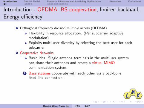
Introduction - OFDMA, BS cooperation, limited backhaul,Energy efficiency
Orthogonal frequency division multiple access (OFDMA)
Flexibility in resource allocation. (Per subcarrier adaptivemodulation)Exploits multi-user diversity by selecting the best user for eachsubcarrier
Cooperative Networks
Basic idea: Single antenna terminals in the multiuser systemcan share their antennas and create a virtual MIMOcommunication system.
1 Base stations cooperate with each other via a backbonefixed-line connection.
Advantages: Reducing the co-channel interference effectivelyvia joint resource allocation.
2 Relaying
Advantages: Low cost implementation with promisingperformance, i.e., coverage extension and diversity gains.
Derrick Wing Kwan Ng FAU 3/27

Introduction System Model Resource Allocation and Scheduling Optimization Simulation Conclusions
Introduction - OFDMA, BS cooperation, limited backhaul,Energy efficiency
Orthogonal frequency division multiple access (OFDMA)
Flexibility in resource allocation. (Per subcarrier adaptivemodulation)
Exploits multi-user diversity by selecting the best user for eachsubcarrier
Cooperative Networks
Basic idea: Single antenna terminals in the multiuser systemcan share their antennas and create a virtual MIMOcommunication system.
1 Base stations cooperate with each other via a backbonefixed-line connection.
Advantages: Reducing the co-channel interference effectivelyvia joint resource allocation.
2 Relaying
Advantages: Low cost implementation with promisingperformance, i.e., coverage extension and diversity gains.
Derrick Wing Kwan Ng FAU 3/27

Introduction System Model Resource Allocation and Scheduling Optimization Simulation Conclusions
Introduction - OFDMA, BS cooperation, limited backhaul,Energy efficiency
Orthogonal frequency division multiple access (OFDMA)
Flexibility in resource allocation. (Per subcarrier adaptivemodulation)Exploits multi-user diversity by selecting the best user for eachsubcarrier
Cooperative Networks
Basic idea: Single antenna terminals in the multiuser systemcan share their antennas and create a virtual MIMOcommunication system.
1 Base stations cooperate with each other via a backbonefixed-line connection.
Advantages: Reducing the co-channel interference effectivelyvia joint resource allocation.
2 Relaying
Advantages: Low cost implementation with promisingperformance, i.e., coverage extension and diversity gains.
Derrick Wing Kwan Ng FAU 3/27

Introduction System Model Resource Allocation and Scheduling Optimization Simulation Conclusions
Introduction - OFDMA, BS cooperation, limited backhaul,Energy efficiency
Orthogonal frequency division multiple access (OFDMA)
Flexibility in resource allocation. (Per subcarrier adaptivemodulation)Exploits multi-user diversity by selecting the best user for eachsubcarrier
Cooperative Networks
Basic idea: Single antenna terminals in the multiuser systemcan share their antennas and create a virtual MIMOcommunication system.
1 Base stations cooperate with each other via a backbonefixed-line connection.
Advantages: Reducing the co-channel interference effectivelyvia joint resource allocation.
2 Relaying
Advantages: Low cost implementation with promisingperformance, i.e., coverage extension and diversity gains.
Derrick Wing Kwan Ng FAU 3/27

Introduction System Model Resource Allocation and Scheduling Optimization Simulation Conclusions
Introduction - OFDMA, BS cooperation, limited backhaul,Energy efficiency
Orthogonal frequency division multiple access (OFDMA)
Flexibility in resource allocation. (Per subcarrier adaptivemodulation)Exploits multi-user diversity by selecting the best user for eachsubcarrier
Cooperative Networks
Basic idea: Single antenna terminals in the multiuser systemcan share their antennas and create a virtual MIMOcommunication system.
1 Base stations cooperate with each other via a backbonefixed-line connection.
Advantages: Reducing the co-channel interference effectivelyvia joint resource allocation.
2 RelayingAdvantages: Low cost implementation with promisingperformance, i.e., coverage extension and diversity gains.
Derrick Wing Kwan Ng FAU 3/27

Introduction System Model Resource Allocation and Scheduling Optimization Simulation Conclusions
1 IntroductionOFDMA and BS cooperationLimited Backhaul and Energy efficiency
2 System ModelMulti-Cell OFDMA network modelAverage Weighted System ThroughputPerformance Measure - Energy Efficiency
3 Resource Allocation and Scheduling OptimizationOptimization Problem FormulationOptimization Solution -Fractional Programming
4 Simulation
5 ConclusionsDerrick Wing Kwan Ng FAU 4/27

Introduction System Model Resource Allocation and Scheduling Optimization Simulation Conclusions
OFDMA, BS cooperation, limited backhaul, Energyefficiency
Backhaul Capacity [1][2][3] Ideal backhaul ⇒ unlimited control signals,
users channel information, and precoding data can always be exchanged.
In practice: Limited backhaul capacity. Finite information
Energy Efficiency (Green communications) Combining a few technologies:
Free lunch?
Power consumptions in circuitries, RF, and backhaul areignored.
[1] O. Somekh, O. Simeone, Y. Bar-Ness, A. Haimovich, and S. Shamai, “Cooperative Multicell
Zero-Forcing Beamforming in Cellular Downlink Channels,” IEEE Trans. Inform. Theory, vol. 55, pp. 3206–3219, Jul. 2009.
[2] R. Zhang, “Cooperative Multi-Cell Block Diagonalization with Per-Base-Station Power Constraints,”
IEEE J. Select. Areas Commun., vol. 28, pp. 1435 –1445, Dec. 2010.
[3] G. Dartmann, W. Afzal, X. Gong, and G. Ascheid, “Joint Optimization of Beamforming, User
Scheduling, and Multiple Base Station Assignment in a Multicell Network,” in Proc. IEEE WirelessCommun. and Networking Conf., Mar. 2011, pp. 209 –214.
Derrick Wing Kwan Ng FAU 4/27

Introduction System Model Resource Allocation and Scheduling Optimization Simulation Conclusions
1 IntroductionOFDMA and BS cooperationLimited Backhaul and Energy efficiency
2 System ModelMulti-Cell OFDMA network modelAverage Weighted System ThroughputPerformance Measure - Energy Efficiency
3 Resource Allocation and Scheduling OptimizationOptimization Problem FormulationOptimization Solution -Fractional Programming
4 Simulation
5 ConclusionsDerrick Wing Kwan Ng FAU 5/27

Introduction System Model Resource Allocation and Scheduling Optimization Simulation Conclusions
System Model
Mobile
MobileMobile
MobileMobile
Mobile
MobileMobile
MobileBase Station
Backhaul connection topology
Central Unit
= BS= User= Backhaul connections with limited
capacities for data exchange
= Backhaul connections for control signals
Figure: A multi-cell system with M = 3 cells with a fully connected backhaullink topology.
Universal frequency reuse, i.e., Frequency reuse factor = 1.
Each transceiver is equipped with a single antenna.
All base stations are cooperating with each other.
Full connection backhaul topology.
Derrick Wing Kwan Ng FAU 5/27

Introduction System Model Resource Allocation and Scheduling Optimization Simulation Conclusions
System Model Base Station
Mobile
Relayed signalOverheard
signal Relay
Base StationBase Station
Backhaul connection
MobileJoint
transmission
Joint transmission
Figure: BSs are connected with backhaul with limited capacities.
The transmitted signal from BS m to all selected users on subcarrier i is given by∑k∈S(i)
xkm(i) =
∑k∈S(i)
wkBm
(i)√
PkBm
(i)uk (i). (1)
The received signal from M BSs at user k on subcarrier i is given by
Y k (i) =
(M∑
c=1
HkBc
(i)wkBc
(i)√
PkBc
(i)lkBc
)uk (i) (2)
+M∑
m=1
∑j∈S(i)
j 6=k
√P j
Bm(i)lk
BmHk
Bm(i)w j
Bm(i)uj (i)
︸ ︷︷ ︸Multiple Access Interference
+zk (i),
Derrick Wing Kwan Ng FAU 6/27

Introduction System Model Resource Allocation and Scheduling Optimization Simulation Conclusions
Instantaneous Channel Capacity: BSs→ User kBase Station
Mobile
Relayed signalOverheard
signal Relay
Base StationBase Station
Backhaul connection
MobileJoint
transmission
Joint transmission
Figure: BSs are connected with backhaul with limited capacities.
Given perfect CSI at the receiver, the channel capacity between all thecooperating BSs and user k on subcarrier i with subcarrier bandwidth B
nFis
given by
C k (i) =BnF
log2
(1 + Γk (i)
), (3)
Γk (i) =
∣∣∣∑Mc=1 Hk
Bc(i)w k
Bc(i)√
PkBc
(i)lkBc
∣∣∣2σ2
z + I k (i), (4)
I k (i) =∑
j∈S(i)j 6=k
∣∣∣ M∑m=1
√P j
Bm(i)w j
Bm(i)√
lkBm
HkBm
(i)∣∣∣2, (5)
Derrick Wing Kwan Ng FAU 7/27

Introduction System Model Resource Allocation and Scheduling Optimization Simulation Conclusions
1 IntroductionOFDMA and BS cooperationLimited Backhaul and Energy efficiency
2 System ModelMulti-Cell OFDMA network modelAverage Weighted System ThroughputPerformance Measure - Energy Efficiency
3 Resource Allocation and Scheduling OptimizationOptimization Problem FormulationOptimization Solution -Fractional Programming
4 Simulation
5 ConclusionsDerrick Wing Kwan Ng FAU 8/27

Introduction System Model Resource Allocation and Scheduling Optimization Simulation Conclusions
Average weighted system throughput
The weighted system capacity is defined as the total number ofbits successfully delivered to the K mobile users and is given by
U(P,W,S) =M∑
m=1
∑k∈Am
αk
nF∑i=1
sk (i)C k (i),
where P, W, and S are the power, precoding coefficient, andsubcarrier allocation policies, respectively. sk (i) ∈ 0, 1 is thebinary subcarrier allocation variable.
Derrick Wing Kwan Ng FAU 8/27
Introduction System Model Resource Allocation and Scheduling Optimization Simulation Conclusions
1 IntroductionOFDMA and BS cooperationLimited Backhaul and Energy efficiency
2 System ModelMulti-Cell OFDMA network modelAverage Weighted System ThroughputPerformance Measure - Energy Efficiency
3 Resource Allocation and Scheduling OptimizationOptimization Problem FormulationOptimization Solution -Fractional Programming
4 Simulation
5 ConclusionsDerrick Wing Kwan Ng FAU 9/27

Introduction System Model Resource Allocation and Scheduling Optimization Simulation Conclusions
Energy Efficiency
Power dissipation in the system:
UTP (P,W,S) = PC ×M︸ ︷︷ ︸Circuits power consumption
+ δ × PBH︸ ︷︷ ︸Backhauls power consumption
+M∑
m=1
K∑k=1
nF∑i=1
εPkBm
(i)|wkBm
(i)|2sk (i)
︸ ︷︷ ︸Power consumption in the RF PAs
, (6)
The objective function, energy efficiency (bit/Joule), is given by
Ueff (P,W,S) =U(P,W,S)
UTP (P,W,S).
Derrick Wing Kwan Ng FAU 9/27

Introduction System Model Resource Allocation and Scheduling Optimization Simulation Conclusions
1 IntroductionOFDMA and BS cooperationLimited Backhaul and Energy efficiency
2 System ModelMulti-Cell OFDMA network modelAverage Weighted System ThroughputPerformance Measure - Energy Efficiency
3 Resource Allocation and Scheduling OptimizationOptimization Problem FormulationOptimization Solution -Fractional Programming
4 Simulation
5 ConclusionsDerrick Wing Kwan Ng FAU 10/27

Introduction System Model Resource Allocation and Scheduling Optimization Simulation Conclusions
Problem Formulation
Problem (Optimization Problem Formulation)
maxP,W,S
Ueff (P,W,S)
s.t. C1:K∑
k=1
nF∑i=1
|wkBm
(i)|2PkBm
(i)sk (i) ≤ PTm , ∀m, [Max. transmit power per BS]
C2:M∑
m=1
K∑k∈Am
nF∑i=1
sk (i)C k (i) ≥ Rmin, [Min. data date requirement]
C3:K∑
k∈Am
nF∑i=1
sk (i)C k (i) ≤ Rmaxm = minRBm1,RBm2
, . . . ,RBmNm, ∀m,
[Backhaul capacity limit]
C4:K∑
k=1
sk (i) ≤ M, ∀i , C5: sk (i) = 0, 1,∀i , k, [Subcarrier constraint]
C6: PkBm
(i) ≥ 0, ∀i , k,m, [Power constraint]
Derrick Wing Kwan Ng FAU 10/27

Introduction System Model Resource Allocation and Scheduling Optimization Simulation Conclusions
1 IntroductionOFDMA and BS cooperationLimited Backhaul and Energy efficiency
2 System ModelMulti-Cell OFDMA network modelAverage Weighted System ThroughputPerformance Measure - Energy Efficiency
3 Resource Allocation and Scheduling OptimizationOptimization Problem FormulationOptimization Solution -Fractional Programming
4 Simulation
5 ConclusionsDerrick Wing Kwan Ng FAU 11/27

Introduction System Model Resource Allocation and Scheduling Optimization Simulation Conclusions
Objective Function Transformation
Without loss of generality, we define the maximum energy efficiency q∗ of theconsidered system as
q∗ =U(P∗,W∗,S∗)
UTP (P∗,W∗,S∗) = maxP,W,S
U(P,W,S)
UTP (P,W,S). (7)
Theorem
The maximum energy efficiency q∗ is achieved if and only if
maxP,W,S
U(P,W,S)− q∗UTP (P,W,S)
= U(P∗,W∗,S∗)− q∗UTP (P∗,W∗,S∗) = 0, (8)
for U(P,W,S) ≥ 0 and UTP (P,W,S) > 0.
Derrick Wing Kwan Ng FAU 11/27

Introduction System Model Resource Allocation and Scheduling Optimization Simulation Conclusions
Equivalent Objective Function
maxP,R,S
Usec (P,R,S)− q∗UTP(P,R,S)
s.t. C1, C2, C3, C4, C5, C6.
Questions:
How to find the optimal q∗?How to solve the above optimization?
Derrick Wing Kwan Ng FAU 12/27
Introduction System Model Resource Allocation and Scheduling Optimization Simulation Conclusions
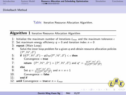
Dinkelbach Method
Table: Iterative Resource Allocation Algorithm.
Algorithm 1 Iterative Resource Allocation Algorithm
1: Initialize the maximum number of iterations Lmax and the maximum tolerance ε2: Set maximum energy efficiency q = 0 and iteration index n = 03: repeat Main Loop4: Solve the inner loop problem for a given q and obtain resource allocation policies
P ′,W ′,S′5: if U(P ′,W ′,S′)− qUTP (P ′,W ′,S′) < ε then6: Convergence = true
7: return P∗,W∗,S∗ = P ′,W ′,S′ and q∗ = U(P′,W′,S′)UTP (P′,W′,S′)
8: else9: Set q = U(P′,W′,S′)
UTP (P′,W′,S′)and n = n + 1
10: Convergence = false11: end if12: until Convergence = true or n = Lmax
Derrick Wing Kwan Ng FAU 13/27

Introduction System Model Resource Allocation and Scheduling Optimization Simulation Conclusions
Power Allocation Optimization
Based on the Dinkelbach iterative algorithm, we solve the following non-convexoptimization problem for a given parameter q:
maxP,W,S
U(P,W,S)− qUTP (P,W,S)
s.t. C1, C2, C3, C4, C5, C6.
Yet,
Joint optimization of precoding vector, power allocation, and subcarrierallocation ⇒ Non-convex problem ⇒ Computational infeasible for number ofvariables.
Precoding scheme: Zero-forcing beamforming.
Subcarrier allocation: Semi-orthogonal user selection.
Power allocation optimization is still non-convex for a given fixed precodingscheme and subcarrier allocation.
Derrick Wing Kwan Ng FAU 14/27

Introduction System Model Resource Allocation and Scheduling Optimization Simulation Conclusions
Theorem
Let P and D denote the optimal values of the primal and the dualproblem, respectively. For a given selected user set and ZFBFtransmission, if the number of subcarriers is sufficiently large, thenstrong duality holds and the duality gap is zero, i.e., P = D.
Derrick Wing Kwan Ng FAU 15/27

Introduction System Model Resource Allocation and Scheduling Optimization Simulation Conclusions
Primal Problem, Perturbation Function, Dual Problem
Without loss of generality, the primal optimization problem can bewritten in general form as
P = maxpk
i ≥0
nF∑i=1
fi 〈pki 〉
s.t.
nF∑i=1
gi 〈pki 〉 ≤ 0. (9)
Then, the perturbation function v〈y〉 and perturbation vector y aredefined as:
v〈y〉 = maxpk
i ≥0
nF∑i=1
fi 〈pki 〉
s.t.
nF∑i=1
gi 〈pki 〉 ≤ y. (10)
Derrick Wing Kwan Ng FAU 16/27

Introduction System Model Resource Allocation and Scheduling Optimization Simulation Conclusions
Primal Problem, Perturbation Function, Dual Problem
The Lagrangian function of (9) can be expressed as
L〈pki ,u〉 =
nF∑i=1
fi 〈pki 〉 − uT
(gi 〈pk
i 〉)
(11)
where u ∈ RL,u ≥ 0 is a vector of Lagrange multipliers. Thus, thecorresponding dual problem is given by
D = minu≥0
maxpk
i
L〈pki ,u〉. (12)
Derrick Wing Kwan Ng FAU 17/27

Introduction System Model Resource Allocation and Scheduling Optimization Simulation Conclusions
Geometric Interpretation of Perturbation Function and Dual Problem
Hyperplane with suboptimal u
y
Hyperplane with optimal u
P
Perturbation functionv(y)
Dual optimal = Primal optimal
Figure: Zero duality gap when maximizing a concave problem.
Derrick Wing Kwan Ng FAU 18/27

Introduction System Model Resource Allocation and Scheduling Optimization Simulation Conclusions
Geometric Interpretation of Duality Gap and Perturbation Function
y
P
Perturbation functionv(y)
Hyperplane with optimal uDual optimal
Primal optimal
Duality gap
Figure: Non-Zero duality gap when maximizing a concave problem.
Derrick Wing Kwan Ng FAU 19/27

Introduction System Model Resource Allocation and Scheduling Optimization Simulation Conclusions
Zero Duality Gap
Theorem
If the perturbation function v〈y〉 is a concave function of y, thenthe duality gap is zero despite the convexity of the primal problem,i.e., D = P.
We need to prove that v〈y〉 is a concave function of y, i.e.,
v〈ρy + (1− ρ)x〉 ≥ ρv〈y〉+ (1− ρ)v〈x〉 (13)
for 0 ≤ ρ ≤ 1, where x ∈ RL is another perturbation vector suchthat x− y 6= 0.How to apply this result to our problem?
Frequency sharing (Large number of subcarriers)
Frequency sharing in multicarrier systems ⇒ Concave perturbationfunction ⇒ Zero Duality gap ⇒ Dual Optimal = Primal Optimal
Derrick Wing Kwan Ng FAU 20/27

Introduction System Model Resource Allocation and Scheduling Optimization Simulation Conclusions
Layer 2 Master Problem - minimization of Dual problem w.r.t
Layer 11 st sub-problem
Layer 12 nd sub-problem
Layer 1th sub-problem
Fn
,μ γGradient update on
,μ γ
[ ] [ ]k F k FP sn n
[2] [2]k kP s
[1] [1]k kP s
,μ γ,μ γ
,μ γ
Figure: An illustration of dual decomposition.
Dual Problem → Dual Decomposition
D = minλ,β, γ≥0
maxP
L(λ,β, γ,P).
L(λ,β, γ,P) =M∑
m=1
nF∑i=1
K∑k∈Am∩S⊥(i)
(αk + γ − βm)C k (i)− γRmin +M∑
m=1
βmRmaxm
−M∑
m=1
λm
( nF∑i=1
K∑k∈S⊥(i)
|wkBm
(i)|2PkBm
(i)− PTm
)
− q( M∑
m=1
K∑k∈Am∩S⊥(i)
nF∑i=1
εPkBm
(i)|wkBm
(i)|2 + δPBH + PC × M),
Derrick Wing Kwan Ng FAU 21/27

Introduction System Model Resource Allocation and Scheduling Optimization Simulation Conclusions
Dual Decomposition Solution in each interaction
Solution of Layer 1 Sub-Problem: The closed-form power allocation for the BSs serving user k in subcarrier i for agiven parameter q is obtained as
PkBm
(i) =
[B/nF (αk + γ − βm)
ln(2)Ωk (i)−
σ2z
|γk (i)|2
]+
and PkBa
(i) = PkBm
(i) ∀a 6= m, where Ωk (i) =( M∑
c=1
(λc + qε)|wkBc
(i)|2).
Solution of Layer 2 Master Problem: The dual function is differentiable and, hence, the gradient method can beused to solve the Layer 2 master problem which leads to
λm(c + 1) =[λm(c)− ξ1(c)×
(PTm −
nF∑i=1
K∑k∈S⊥(i)
|wkBm
(i)|2PkBm
(i))]+, ∀m,
γ(c + 1) =[γ(c)− ξ2(c)×
( M∑m=1
nF∑i=1
K∑k∈Am∩S⊥(i)
C k (i)− Rmin
)]+,
βm(c + 1) =[βm(c)− ξ3(c)×
(Rmaxm −
nF∑i=1
K∑k∈Am∩S⊥(i)
C k (i))]+
, ∀m.
Derrick Wing Kwan Ng FAU 22/27
Introduction System Model Resource Allocation and Scheduling Optimization Simulation Conclusions
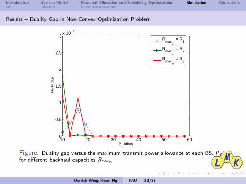
Results – Duality Gap in Non-Convex Optimization Problem
10 20 30 40 50 600
0.5
1
1.5
2
2.5
3x 10
−7
PT (dBm)
Dua
lity
gap
R
maxm
= R1
Rmax
m
= R2
Rmax
m
= R3
Figure: Duality gap versus the maximum transmit power allowance at each BS, PT ,for different backhaul capacities Rmaxm .
Derrick Wing Kwan Ng FAU 23/27

Introduction System Model Resource Allocation and Scheduling Optimization Simulation Conclusions
Results – Energy Efficiency for Different Limited Backhaul Capacities
10 15 20 25 30 35 40 45 50 550
0.5
1
1.5
2
2.5
3
3.5
4
4.5x 10
5
PT (dBm)
Ene
rgy
effic
ienc
y (b
it/Jo
ule)
Proposed algorithm and baseline
Rmax
m
= 11 Mb/s
Baseline R
maxm
=34 Mb/s,
Rmax
m
= 44Mb/s,
Proposed algorithm, R
maxm
=34 Mb/s,
Rmax
m
= 44Mb/s,
Figure: Energy efficiency (bit-per-Joule) versus the maximum transmit powerallowance at each BS PT . Baseline scheme is a resource allocator which maximizesthe system throughput.
Derrick Wing Kwan Ng FAU 24/27

Introduction System Model Resource Allocation and Scheduling Optimization Simulation Conclusions
Results – Average Capacity for Different Limited Backhaul Capacities
10 15 20 25 30 35 40 45 50 556
8
10
12
14
16
18
20
22
24
PT (dBm)
Ave
rage
sys
tem
cap
acity
(bi
t/s/H
z/ce
ll)
Baseline
Rmax
m
= R2, R
maxm
= R3
Proposed algorithm and baseline
Rmax
m
= R1
Proposed algorithm, Rmax
m
= R2,
Rmax
m
= R3
Figure: Average outage capacity (bit/s/Hz) versus the maximum transmit powerallowance at each BS, PT , for different resource allocation algorithms and differentbackhaul capacities with K = 45 users. Baseline scheme is a resource allocators whichmaximizes the system throughput.
Derrick Wing Kwan Ng FAU 25/27

Introduction System Model Resource Allocation and Scheduling Optimization Simulation Conclusions
Conclusions
The resource allocation algorithm design for BS cooperativeOFDMA systems was formulated as a non-convexoptimization problem.
Power allocation was optimized for energy efficiencymaximization for the non-convex optimization problem.
We showed that when the number of subcarriers is sufficientlylarge, the duality gap is practically zero despite thenon-convexity of the primal problem.
An efficient power allocation was obtained by solving the dualproblem.
Simulation results demonstrated the trade-off betweenbackhaul capacity and energy efficiency.
Derrick Wing Kwan Ng FAU 26/27

Introduction System Model Resource Allocation and Scheduling Optimization Simulation Conclusions
Q&A
Derrick Wing Kwan Ng FAU 27/27