Embed Size (px)
Citation preview

20
14
E n e r g y e f f i c i e n c y o r i e n t e d
Materials, Machines and Advanced Electromagnetic Devices
Highlights
20
14
E n e r g y e f f i c i e n c y o r i e n t e d
Highlights 2014
MADEA
1
Foreword MADEA: Materials, Machines and Advanced Electromagnetic Devices
The MADEA team has multidisciplinary activities, aiming design of innovative systems through material knowledge and their potential applications in Electrical Engineering. Its research field covers from materials to applications and associated phenomena analysis, modelling and experimentation.
The researches of the MADEA team are structured in three axes:
• StudyoffunctionalmaterialsforElectricalEngineeringMADEA is working on magnetic materials, superconductors and magnetocaloric materials. It involves improvement and optimization of these materials and apprehension of behaviour laws taking into account material physics.
• ResearchoninnovativeelectromagneticdevicesforenergyconversionandprocessingThe approach is based on rational use of materials, especially magnetic materials, and study of new device structures exploiting the full potential of these materials.
•DesignofinnovativeelectromagneticdevicesforinformationconversionandprocessingMADEA team works on magnetic field sensors and physical quantity sensors (electric current, position, torque, etc.).
Highlights 2014
MADEA
3
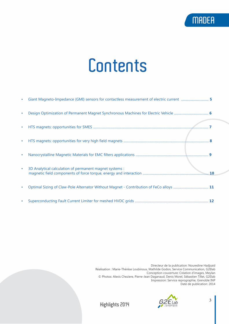
• GiantMagneto-Impedance(GMI)sensorsforcontactlessmeasurementofelectriccurrent................................. 5
• DesignOptimizationofPermanentMagnetSynchronousMachinesforElectricVehicle......................................... 6
• HTSmagnets:opportunitiesforSMES.......................................................................................................................................... 7
• HTSmagnets:opportunitiesforveryhighfieldmagnets...................................................................................................... 8
• NanocrystallineMagneticMaterialsforEMCfiltersapplications....................................................................................... 9
• 3DAnalyticalcalculationofpermanentmagnetsystems:magneticfieldcomponentsofforcetorque,energyandinteraction............................................................................... 10
• OptimalSizingofClaw-PoleAlternatorWithoutMagnet-ContributionofFeCoalloys.......................................... 11
• SuperconductingFaultCurrentLimiterformeshedHVDCgrids........................................................................................ 12
Directeurdelapublication:NouredineHadjsaidRéalisation:Marie-ThérèseLoubinoux,MathildeGodon,ServiceCommunication,G2Elab
Conceptioncouverture:Créationd’images,Meylan©Photos:AlexisCheziere,Pierre-JeanDaganaud,DenisMorel,SébastienTillet,G2Elab
Impression:Servicereprographie,GrenobleINPDatedepublication:2014
Contents
Highlights 2014
MADEA
5
ContaCtsAktham [email protected] [email protected]
Further reading
A high dynamic range GMI curent sensor Journal of Sensor Technology, 2012, 2, 165 - 171Doi:10.4236/jst.2012.24023
Giant Magneto-Impedance (GMI) sensors for contactless measurement of electric current
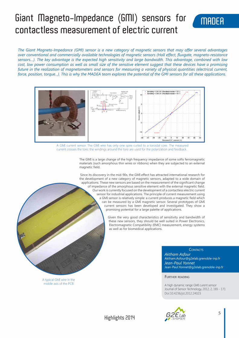
The Giant Magneto-Impedance (GMI) sensor is a new category of magnetic sensors that may offer several advantages over conventional and commercially available technologies of magnetic sensors (Hall effect, fluxgate, magneto-resistance sensors…). The key advantage is the expected high sensitivity and large bandwidth. This advantage, combined with low cost, low power consumption as well as small size of the sensitive element suggest that these devices have a promising future in the realization of magnetometers and sensors for measuring a variety of physical quantities (electrical current, force, position, torque...). This is why the MADEA team explores the potential of the GMI sensors for all these applications.
TheGMIisalargechangeofthehighfrequencyimpedanceofsomesoftsferromagneticmaterials(suchamorphousthinwiresorribbons)whentheyaresubjectedtoanexternalmagneticfield.
Sinceitsdiscoveryinthemid-90s,theGMIeffecthasattractedinternationalresearchforthedevelopmentofanewcategoryofmagneticsensors,adaptedtoawidedomainofapplications.Thesenewsensorsarebasedonthemeasurementofthesignificantchange
ofimpedanceoftheamorphoussensitiveelementwiththeexternalmagneticfield.Ourworkiscurrentlyfocusedonthedevelopmentofacontactlesselectriccurrentsensorforindustrialapplications.TheprincipleofcurrentmeasurementusingaGMIsensorisrelativelysimple:acurrentproducesamagneticfieldwhichcanbemeasuredbyaGMImagneticsensor.SeveralprototypesofGMIcurrent sensors has been developed and investigated. They show apromisingpotentialforalargepaletteofapplications.
Giventheverygoodcharacteristicsofsensitivityandbandwidthofthesenewsensors,theyshouldbewellsuitedinPowerElectronics,ElectromagneticCompatibility(EMC)measurement,energysystemsaswellasforbiomedicalapplications.
A GMI current sensor. The GMI wire has only one spire curled to a toroidal core. The measured current crosses the tore; the windings around the tore are used for the polarization and feedback.
A typical GMI wire in the middle axis of the PCB
MADEA
6
Design Optimization of Permanent Magnet Synchronous Machines for Electric Vehicle
Due to the use of permanent magnets in the rotor, Permanent Magnet Synchronous Machines (PMSM) have the highest power density and efficiency among all types of motors. Therefore, PMSM have found wide attention in designing machines for a lot of high performance industrial applications as in transportation and Electric Vehicle (EV). In the same time, specifications of such applications present severe constraints and the challenge of designers is to find the best machines giving the best performances.
ContaCtsFrédéric [email protected] [email protected]
Further reading
[1] Analysis of Slots-Poles Combination of Frac-tional-Slots PMSM for Embedded Applications H.Dogan, F. Wurtz, A. Foggia and L. Garbuio IEEE Aegean Conference on Electr. Machines & Power Electronics, ACEMP’11, Istanbul, Turkey, Sept. 2011 [2] Multistatic Reluctance Network Modeling for the Design of PMSM H. Dogan, L. Garbuio, H. Nguyen-Xuan, B. Delinchant, A. Foggia and F. Wurtz IEEE Conference on Electromagnetic Field Computation, CEFC’12, Oita, Japan, Nov. 2012
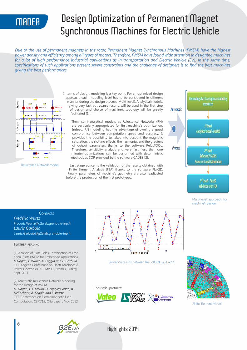
Intermsofdesign,modelingisakeypoint.Foranoptimizeddesignapproach, eachmodeling level has tobe considered indifferentmannerduringthedesignprocess(Multi-level).Analyticalmodels,givingveryfastbutcoarseresults,willbeusedinthefirststepof design and choice of machine’s topology will be greatlyfacilitated[1].
Then, semi-analytical models as Reluctance Networks (RN)areparticularlyappropriated forfirstmachine’soptimization.Indeed, RNmodeling has the advantage of owning a goodcompromise between computation speed and accuracy. Itprovides the possibility to takes into account the magneticsaturation,theslottingeffects,theharmonicsandthegradientof output parameters thanks to the software RelucTOOL.Therefore, sensitivity analysis and very fast (less than oneminute) optimizations can be performed with deterministicmethodsasSQPprovidedbythesoftwareCADES[2].
LaststageconcernsthevalidationoftheresultsobtainedwithFinite Element Analysis (FEA) thanks to the software Flux2D.Finally, parameters of machine’s geometry are also readjustedbeforetheproductionofthefirstprototypes.
Finite Element Model
Validation results between RelucTOOL & Flux2D
Multi-level approach for machine’s design
Reluctance Network model
Highlights 2014
Industrialpartners:
Highlights 2014
MADEA
7
HTS magnets: opportunities for SMES
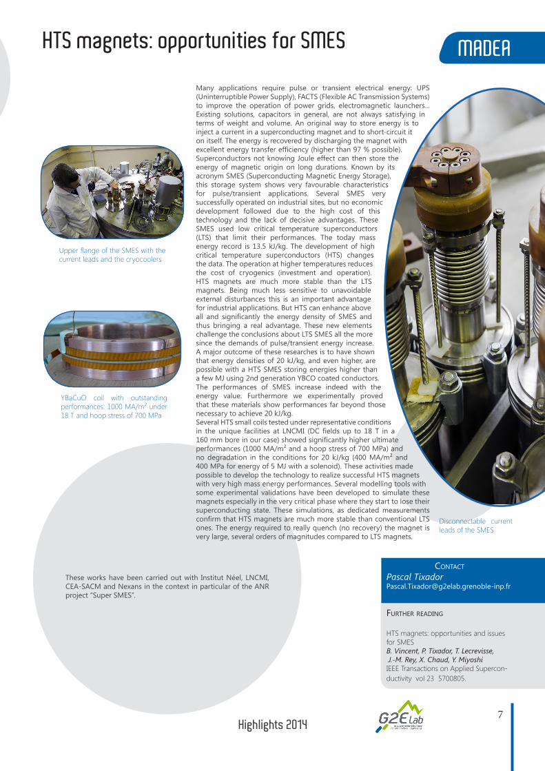
Many applications require pulse or transient electrical energy: UPS(UninterruptiblePowerSupply),FACTS(FlexibleACTransmissionSystems)to improve the operation of power grids, electromagnetic launchers...Existing solutions, capacitors in general, are not always satisfying intermsofweight and volume.Anoriginalway to store energy is toinjectacurrentinasuperconductingmagnetandtoshort-circuititonitself.Theenergyisrecoveredbydischargingthemagnetwithexcellentenergytransferefficiency(higherthan97%possible).SuperconductorsnotknowingJouleeffectcanthenstoretheenergy ofmagnetic origin on long durations. Known by itsacronymSMES(SuperconductingMagneticEnergyStorage),this storage system shows very favourable characteristicsfor pulse/transient applications. Several SMES verysuccessfullyoperatedonindustrialsites,butnoeconomicdevelopment followed due to the high cost of thistechnology and the lack of decisive advantages. TheseSMES used low critical temperature superconductors(LTS) that limit their performances. The today massenergy record is 13.5 kJ/kg. Thedevelopmentofhighcritical temperature superconductors (HTS) changesthedata.Theoperationathighertemperaturesreducesthe cost of cryogenics (investment and operation).HTS magnets are much more stable than the LTSmagnets. Being much less sensitive to unavoidableexternal disturbances this is an important advantageforindustrialapplications.ButHTScanenhanceaboveall and significantly the energy density of SMES andthus bringing a real advantage. These new elementschallengetheconclusionsaboutLTSSMESallthemoresincethedemandsofpulse/transientenergy increase.Amajoroutcomeoftheseresearchesistohaveshownthatenergydensitiesof20kJ/kg,andevenhigher,arepossiblewithaHTSSMESstoringenergieshigherthanafewMJusing2ndgenerationYBCOcoatedconductors.The performances of SMES increase indeed with theenergy value. Furthermore we experimentally provedthatthesematerialsshowperformancesfarbeyondthosenecessarytoachieve20kJ/kg.SeveralHTSsmallcoilstestedunderrepresentativeconditionsin the unique facilities at LNCMI (DC fields up to 18 T in a160mmboreinourcase)showedsignificantlyhigherultimateperformances(1000MA/m²andahoopstressof700MPa)andnodegradation in the conditions for 20 kJ/kg (400MA/m² and400MPaforenergyof5MJwithasolenoid).TheseactivitiesmadepossibletodevelopthetechnologytorealizesuccessfulHTSmagnetswithveryhighmassenergyperformances.Severalmodellingtoolswithsomeexperimental validationshavebeendeveloped tosimulate thesemagnetsespeciallyintheverycriticalphasewheretheystarttolosetheirsuperconducting state. These simulations, as dedicatedmeasurementsconfirmthatHTSmagnetsaremuchmorestablethanconventionalLTSones.Theenergyrequiredtoreallyquench(norecovery)themagnetisverylarge,severalordersofmagnitudescomparedtoLTSmagnets.
ContaCtPascal [email protected]
Further reading
HTS magnets: opportunities and issues for SMESB. Vincent, P. Tixador, T. Lecrevisse, J.-M. Rey, X. Chaud, Y. MiyoshiIEEE Transactions on Applied Supercon-ductivity vol 23 5700805.
Theseworkshavebeencarriedoutwith InstitutNéel,LNCMI,CEA-SACMandNexansinthecontextinparticularoftheANRproject“SuperSMES”.
Upper flange of the SMES with the current leads and the cryocoolers
YBaCuO coil with outstanding performances: 1000 MA/m² under 18 T and hoop stress of 700 MPa
Disconnectable current leads of the SMES
Highlights 2014
MADEA
8
HTS magnets: opportunities for very high field magnets
The discovery of the Higgs boson in 2012 was aworldwide event, possible thanks to the LHC, thesuperconductingcollideratCERN.ButthequestforthefundamentallawsofUniversedoesnotstop.Therearenumerousunsolvedquestions,suchas super symmetry, for which colliders ofhigherenergy,thushighermagneticfields,arerequired.The constraints on superconducting(SC) acceleratormagnet design are se-vere:veryhighcurrentdensities(higherthan300to400MA/m²)duetospaceconstraints, outstanding field qualityforasuitablebeamoptics…Theelec-tromagnetic stressesarehugeonSCconductors since they experienceboth high current densities andmagneticfluxdensities.Thefieldlimitfor low critical temperature super-conductingmagnetsisabout15-16T.But the outstanding current trans-port properties of high temperaturesuperconductorsatlowtemperaturesopen the road to higher magneticfields.YBCOcoatedconductorsshowanoverallcurrentdensityhigherthan1000MA/m²at4Kunderalongitudi-nalmagneticfluxdensityof35T.WithintheECEuCARDproject,coordinatedbyCERN, theG2ELabwith InstitutNéel ledthe“highfield”task,incooperation,LNC-MIandCEAamongothers.The possibility of using YBCO conductorto build an insert dipole was investigated,leading to the development of a 1st of a
kind HTS dipole that will be tested in an outerNb3Sn magnetunderdevelopment. The activities
passed through several steps, from characterizationsof available conductors to modelling work focused on
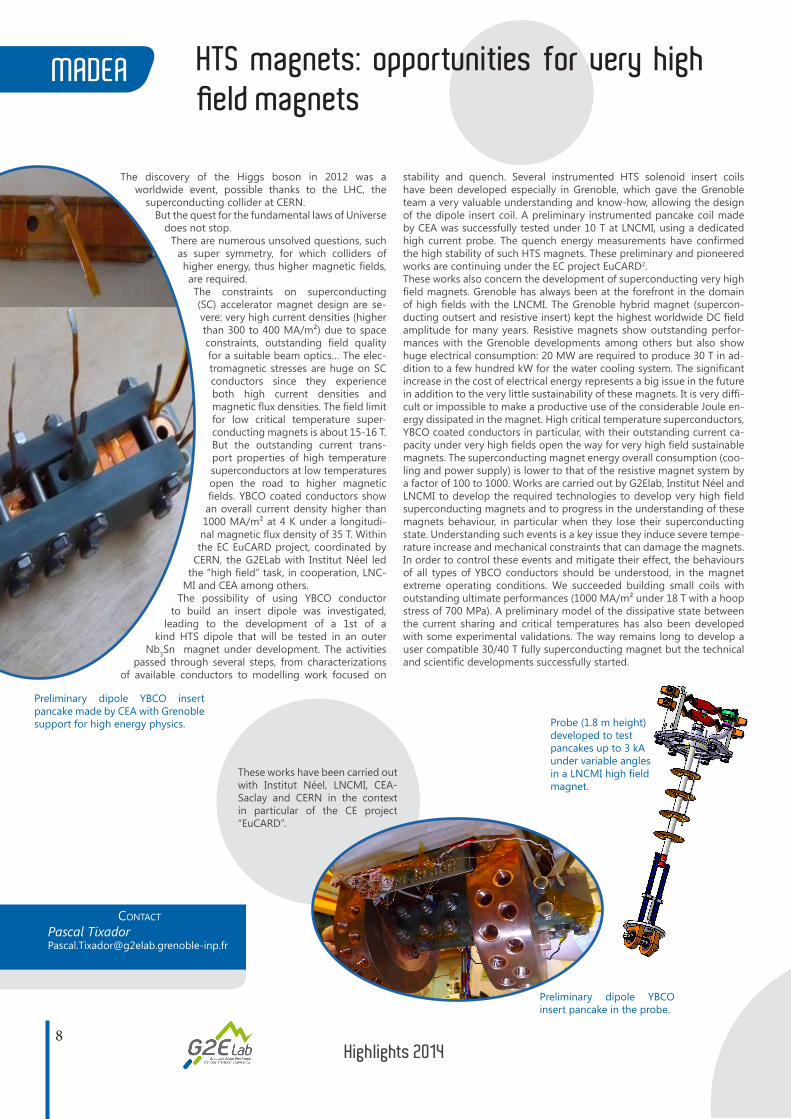
stability and quench. Several instrumented HTS solenoid insert coilshavebeendevelopedespecially inGrenoble,whichgave theGrenobleteamaveryvaluableunderstandingandknow-how,allowingthedesignofthedipoleinsertcoil.ApreliminaryinstrumentedpancakecoilmadebyCEAwassuccessfullytestedunder10TatLNCMI,usingadedicatedhighcurrentprobe.ThequenchenergymeasurementshaveconfirmedthehighstabilityofsuchHTSmagnets.ThesepreliminaryandpioneeredworksarecontinuingundertheECprojectEuCARD2.Theseworksalsoconcernthedevelopmentofsuperconductingveryhighfieldmagnets.GrenoblehasalwaysbeenattheforefrontinthedomainofhighfieldswiththeLNCMI.TheGrenoblehybridmagnet (supercon-ductingoutsertandresistiveinsert)keptthehighestworldwideDCfieldamplitude formanyyears.Resistivemagnets showoutstandingperfor-manceswith theGrenobledevelopments amongothersbut also showhugeelectricalconsumption:20MWarerequiredtoproduce30Tinad-ditiontoafewhundredkWforthewatercoolingsystem.Thesignificantincreaseinthecostofelectricalenergyrepresentsabigissueinthefutureinadditiontotheverylittlesustainabilityofthesemagnets.Itisverydiffi-cultorimpossibletomakeaproductiveuseoftheconsiderableJouleen-ergydissipatedinthemagnet.Highcriticaltemperaturesuperconductors,YBCOcoatedconductorsinparticular,withtheiroutstandingcurrentca-pacityunderveryhighfieldsopenthewayforveryhighfieldsustainablemagnets.Thesuperconductingmagnetenergyoverallconsumption(coo-lingandpowersupply)islowertothatoftheresistivemagnetsystembyafactorof100to1000.WorksarecarriedoutbyG2Elab,InstitutNéelandLNCMItodeveloptherequiredtechnologiestodevelopveryhighfieldsuperconductingmagnetsandtoprogressintheunderstandingofthesemagnetsbehaviour, inparticularwhen they lose their superconductingstate.Understandingsucheventsisakeyissuetheyinduceseveretempe-ratureincreaseandmechanicalconstraintsthatcandamagethemagnets.Inordertocontroltheseeventsandmitigatetheireffect,thebehavioursof all typesof YBCOconductors shouldbeunderstood, in themagnetextreme operating conditions.We succeeded building small coils withoutstandingultimateperformances(1000MA/m²under18Twithahoopstressof700MPa).Apreliminarymodelofthedissipativestatebetweenthe current sharing and critical temperatures has also beendevelopedwithsomeexperimentalvalidations.Thewayremainslongtodevelopausercompatible30/40Tfullysuperconductingmagnetbutthetechnicalandscientificdevelopmentssuccessfullystarted.
Probe(1.8mheight)developedtotestpancakesupto3kAundervariableanglesinaLNCMIhighfieldmagnet.
Preliminary dipole YBCO insertpancakemadebyCEAwithGrenoblesupportforhighenergyphysics.
Preliminary dipole YBCOinsertpancakeintheprobe.
ContaCtPascal [email protected]
Theseworkshavebeencarriedoutwith Institut Néel, LNCMI, CEA-Saclay and CERN in the contextin particular of the CE project“EuCARD”.
Highlights 2014
MADEA
9
ContaCtHervé [email protected]
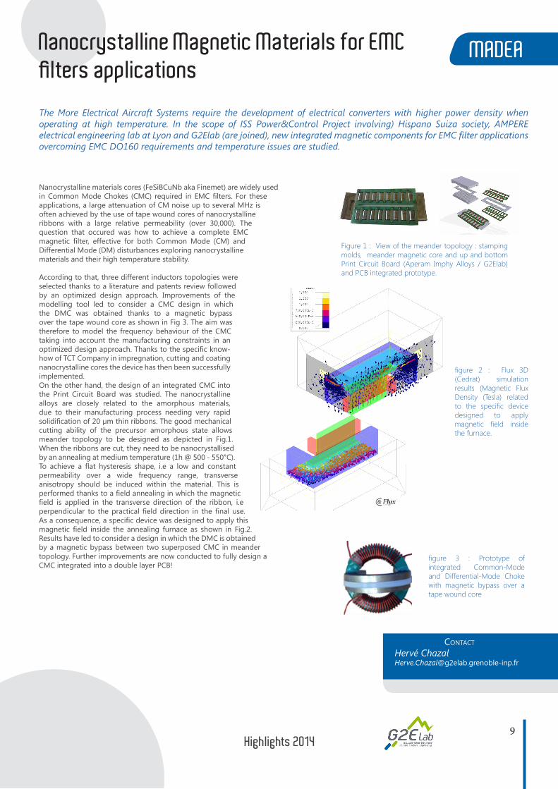
Nanocrystalline Magnetic Materials for EMC filters applications
The More Electrical Aircraft Systems require the development of electrical converters with higher power density when operating at high temperature. In the scope of ISS Power&Control Project involving) Hispano Suiza society, AMPERE electrical engineering lab at Lyon and G2Elab (are joined), new integrated magnetic components for EMC filter applications overcoming EMC DO160 requirements and temperature issues are studied.
Nanocrystallinematerialscores(FeSiBCuNbakaFinemet)arewidelyusedinCommonModeChokes (CMC) required inEMCfilters. For theseapplications,alargeattenuationofCMnoiseuptoseveralMHzisoftenachievedbytheuseoftapewoundcoresofnanocrystallineribbons with a large relative permeability (over 30,000). Thequestion that occured was how to achieve a complete EMCmagnetic filter, effective for both CommonMode (CM) andDifferentialMode(DM)disturbancesexploringnanocrystallinematerialsandtheirhightemperaturestability.
Accordingtothat,threedifferentinductorstopologieswereselectedthankstoaliteratureandpatentsreviewfollowedby an optimized design approach. Improvements of themodelling tool led to consider a CMC design in whichthe DMC was obtained thanks to a magnetic bypassoverthetapewoundcoreasshowninFig3.Theaimwastherefore tomodel the frequencybehaviourof theCMCtaking into account themanufacturing constraints in anoptimizeddesignapproach.Thankstothespecificknow-howofTCTCompanyinimpregnation,cuttingandcoatingnanocrystallinecoresthedevicehasthenbeensuccessfullyimplemented.Ontheotherhand,thedesignofanintegratedCMCintothe Print Circuit Board was studied. The nanocrystallinealloys are closely related to the amorphous materials,due to their manufacturing process needing very rapidsolidificationof20µmthinribbons.Thegoodmechanicalcutting ability of the precursor amorphous state allowsmeander topology to be designed as depicted in Fig.1.Whentheribbonsarecut,theyneedtobenanocrystallisedbyanannealingatmediumtemperature(1h@500-550°C).To achieve a flat hysteresis shape, i.e a low and constantpermeability over a wide frequency range, transverseanisotropy should be induced within the material. This isperformedthankstoafieldannealinginwhichthemagneticfield is applied in the transverse direction of the ribbon, i.eperpendicular to thepractical fielddirection in thefinal use.Asaconsequence,aspecificdevicewasdesignedtoapplythismagnetic field inside the annealing furnace as shown in Fig.2.ResultshaveledtoconsideradesigninwhichtheDMCisobtainedbyamagneticbypassbetweentwosuperposedCMCinmeandertopology.FurtherimprovementsarenowconductedtofullydesignaCMCintegratedintoadoublelayerPCB!
figure 3 : Prototype of integrated Common-Mode and Differential-Mode Choke with magnetic bypass over a tape wound core
Figure 1 : View of the meander topology : stamping molds, meander magnetic core and up and bottom Print Circuit Board (Aperam Imphy Alloys / G2Elab) and PCB integrated prototype.
figure 2 : Flux 3D (Cedrat) simulation results (Magnetic Flux Density (Tesla) related to the specific device designed to apply magnetic field inside the furnace.
Highlights 2014
MADEA
10
3D Analytical calculation of permanent magnet systems : magnetic field components of force torque, energy and interaction
ContaCtJean-Paul [email protected]
Further reading
Three-Dimensional Analytical Calculation of Permanent Magnet Interactions by “Magnetic Node” RepresentationJ.-P. Yonnet and H. AllagIEEE Transaction on Magnetics, Volume 47, n° 8, Aug 2011, p. 2050 – 2055
Analytical Calculation of Magnet Systems: Magnetic Field Created by Charged Triangles and PolyhedraC. Rubeck , J-P. Yonnet , H. Allag , B. Delinchant, and O. ChadebecIEEE Trans on Magn, Vol. 49, No. 1, Part 1, January 2013, p. 144 – 147
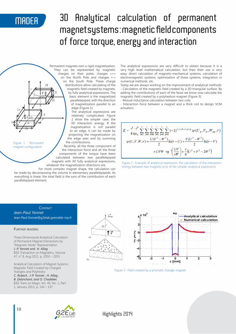
Permanentmagnetsownarigidmagnetization.They can be represented by magneticcharges on their poles: charges «+»on the North Pole and charges «-»on the South Pole. These chargedistributionsallowcalculatingofthemagneticfieldcreatedbymagnets,byfullyanalyticalexpressions.Thebasicelementisthemagnetizedparallelepiped,withthedirectionofmagnetizationparallel toanedge(Figure1).The analytical expressions arerelatively complicated; Figure2 show the simpler case: the3D interaction energy. If themagnetization is not parallelto an edge, it can bemade byprojecting themagnetization onthe edge axes and by summingthecontributions.Recently,allthethreecomponentoftheinteractionforceandallthethree
components of the torque have beencalculated between two parallelepiped
magnetswith3D fullyanalyticalexpressions,whateverthemagnetizationdirectionsare.
Formore complexmagnet shape, the calculation canbemadebydecomposingthevolumeinelementaryparallelepipeds.Aseverythingislinear,thetotalfieldisthesumofthecontributionofeachparallelepipedelement.
The analytical expressions are very difficult to obtain because it is avery high level mathematical calculation, but then their use is veryeasy: direct calculation ofmagneto-mechanical systems, calculation ofelectromagnetic systems, optimization of these systems, integration innumericalmethods,etc.Todaywearealwaysworkingontheimprovementofanalyticalmethods:-Calculationofthemagneticfieldcreatedbya3Dtriangularsurface.Byaddingthecontributionsofeachofthefacesweknownowcalculatethemagneticfieldcreatedbyapolyhedronmagnet(Figure3).-Mutualinductancecalculationbetweentwocoils- Interaction force between amagnet and a thick coil to design VCMactuators.
Figure 3 : Field created by a prismatic triangle magnet
Figure 2 : Example of analytical expression, the calculation of the interaction energy between two magnets (one of the simpler analytical expression)
Figure 1 : Permanent magnet configuration

Highlights 2014
MADEA
11
Optimal Sizing of Claw-Pole Alternator Without Magnet - Contribution of FeCo alloys
Claw-pole alternators are often used in automotive industry. Permanent magnets like NdFEB are currently integrated to increased the power density of claw-pole machine. However their higher price and their availabilities brings into question their usage. This tight context implies finding new technical solutions to keep the same power density without NdFeB magnets. The solution adopted consists to evaluate the potential of gain with different soft magnetic materials and more especially FeCo family (AFK18, AFK1 et AFK502).
FeComaterialoffershighsaturationpolarizationandhighpermeabilitybuttheirhigherpriceimposedustouseitwithmoderationandsmartness.Inthisstudy,wehaveevaluatedtheirusageandshownthatFeCocorealternatorcanreachthesameperformancesofinitialstructure[1].Unlikeconventionalelectricalmachines,claw-polemachineischaracterizedbyitsunsymmetricalshapeofpolesalongtherotorthatinducesa3Dfluxpath.Inthiscontext,amodelbasedonamagneticequivalentcircuit(MEC)isestablishedtoperformoptimizationsunderconstraintsincludingshorttime simulation and high parameters number. In our case, themodelaccuracyisabout30%butitwasadequatetoachievepredesignofthealternator.Resultsdemonstrate theCoFeability to increase theoutputcurrentatlowspeed.AlternatorpredesignsachievedwiththeMECmodelshowedthatusingsolidCoFerotorshouldincreasethecurrentflowof30%to70%atlowspeed.Inoptimizationaspect, this work is based on an adapted designmethodologyincludingtwomodelinglevel(magneticequivalentcircuitmodelandfiniteelementmodel)inordertoobtainagoodcompromisebetweentimecomputation/accuracy[2].
ContaCtsAfef [email protected] [email protected]
Further reading
[1] Optimisation of a claw-pole alternator using solid cofe rotorPerez S., Garbuio L., Foggia A., Kedous-Lebouc A. and Mipo J-CSMM 2013, Budapest, Hongrie, 2013
[2] Modeling of claw-pole alternator with a global reluctance model based on improved equivalent magnetic circuits with objective of robustness Perez S., Garbuio L., Foggia A., Kedous-Lebouc A. and Mipo J-CIEEE Conference on Electromagnetic Field Computation, CEFC’12, Oita, Japan, Nov. 2012
Multi-levelConceptionStrategy:PredesignandDesign
OptimizationofaClawpolegenerator:a3Dproblem
ReluctanceNetworkModelforwideandcomplexoptimizationproblem
ImprovementofoutputpowerwithoptimalFeCocore(FEMresults)
Industrialpartners:
Highlights 2014
MADEA
12
Superconducting Fault Current Limiter for meshed HVDC grids
ContaCtsPascal [email protected] [email protected] [email protected]
Further reading
Innovative distribution networks planning integrating superconducting fault current limitersC. Gandioli, M.-C. Alvarez Hérault, P. Tixador, N. Hadjsaid, D. M. Rojas MedinaIEEE Transactions on Applied Superconductivity vol 23
Design and production of Eccoflow Resistive Fault Current LimiterA. Hobl, W. Goldacker, B. Dutoit, L. Martini, A. Petermann, P. TixadorIEEE Transactions on Applied Superconductivity vol 23
Protection system for meshed HVDC network using superconducting fault current limitersJ. Descloux, C. Gandioli, B. Raison, N. Hadjsaid, P. TixadorIEEE grenoble powerTech 2013
Meshed High Voltage Direct Current (HVDC) grids areforeseenasaneconomical,suitableandveryefficientsolutionforthetransfersoflargeamountrenewableenergies through submarine cables or/and onlongdistances:offshorewindgenerationfarmsand desert solar energies. Nevertheless thisattractive technology faces the technicalhurdle of managing fault currents. In DCit is no more possible to take advantageof the AC current zero-crossing in orderto clear a fault. Whereas it is possibleto fix this issue in today point-to-pointHVDC transmissions by interruptingthecurrentontheACsides, itbecomesa difficult task and significant lock inmeshed HVDC grids. The control ofthe voltage converters does not allowhandling the fault currents due to thediodes connected anti-parallel acrossthe controlled switches. The estimationsof the fault currents in meshed HVDCgrids overstep the switching and clearingcapacity of the state of the art DC circuitbreaker and destroy the diodes of theconverter.This very annoying problem could be solvedbyusingSuperconductingFaultCurrentlimiters
(SCFCL) whose first medium voltage devices areinstalledingrids.G2ElabandInstitutNéelhavelong
experience and know-how on SCFCL design and gridintegration.
RecentlytheyparticipatedtotheEccoflowEUproject(figure1),oneofthemostambitiousprojectworldwideonSuperconductingtechnologiesapplications.TheSCFCLisbasedontheintrinsichighlynonlinearvoltageversus current characteristic of a superconducting element. Under agivenDCcurrentthevoltageacrossitisnearlyundetectablemakingitinvisibleforthegrid.Ontheotherhand,assoonasacurrentoverstepsthis given current a high voltage develops itself automatically andnaturally,whichlimitsthefaultcurrentamplitudewithoutanyexternalaction.Acircuitbreaker is required to isolate thesuperconductorandavoiditsdamaging.Thesuperconductinglengthcanbefavourablyusedtoshowaninductancetolimitthefaultcurrentrise.InDCsystems,thissuperconducting inductance does not introduce any voltage drop innormalandsteadystateoperation.
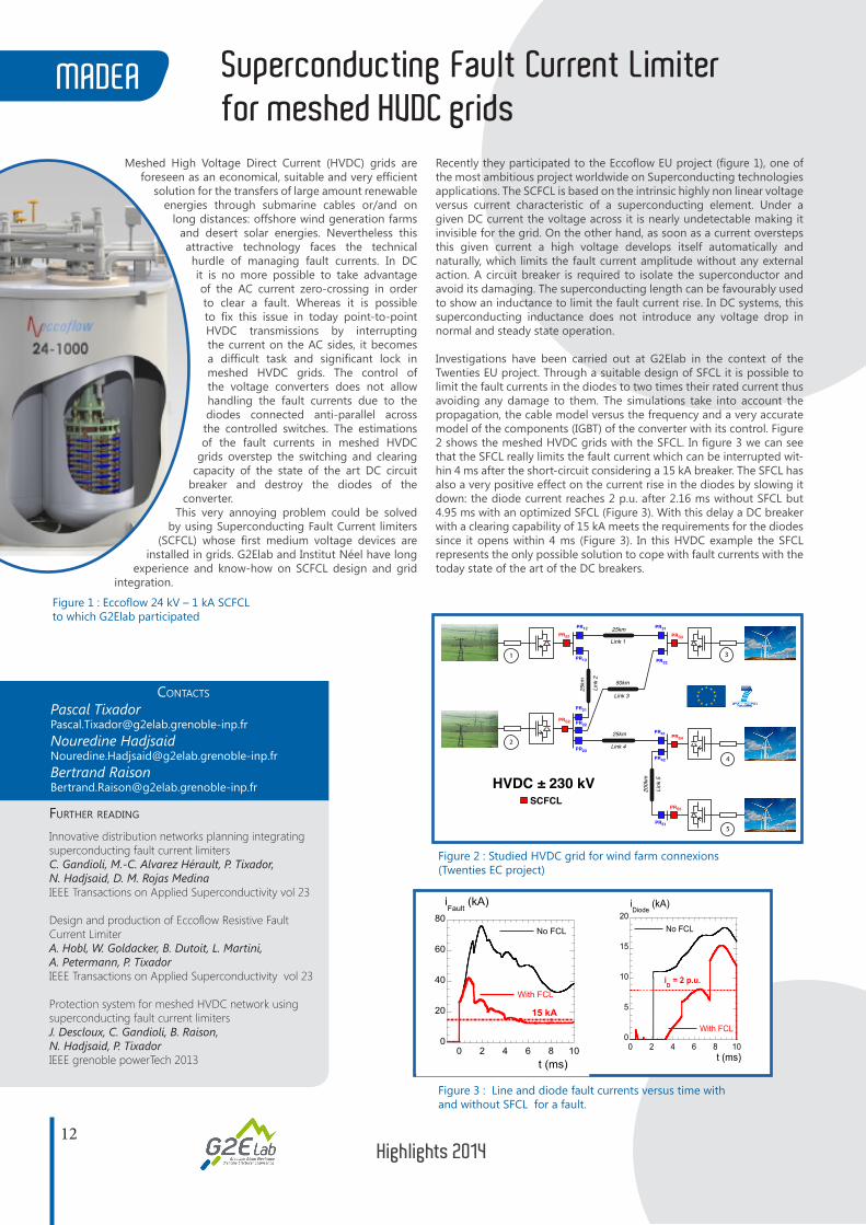
Investigations have been carried out at G2Elab in the context of theTwentiesEUproject.ThroughasuitabledesignofSFCLitispossibletolimitthefaultcurrentsinthediodestotwotimestheirratedcurrentthusavoiding anydamage to them. The simulations take into account thepropagation,thecablemodelversusthefrequencyandaveryaccuratemodelofthecomponents(IGBT)oftheconverterwithitscontrol.Figure2showsthemeshedHVDCgridswiththeSFCL.Infigure3wecanseethattheSFCLreallylimitsthefaultcurrentwhichcanbeinterruptedwit-hin4msaftertheshort-circuitconsideringa15kAbreaker.TheSFCLhasalsoaverypositiveeffectonthecurrentriseinthediodesbyslowingitdown:thediodecurrentreaches2p.u.after2.16mswithoutSFCLbut4.95mswithanoptimizedSFCL(Figure3).WiththisdelayaDCbreakerwithaclearingcapabilityof15kAmeetstherequirementsforthediodessince itopenswithin4ms (Figure3). In thisHVDCexample theSFCLrepresentstheonlypossiblesolutiontocopewithfaultcurrentswiththetodaystateoftheartoftheDCbreakers.
1
2
3
4
25km
50km
Link 3
25km
25km
200k
mLink 1
Link 4
Link
2
Link
5PR13
HVDC ± 230 kVSCFCL
PR12 PR31
PR32
PR41
PR42
PR21
PR22
PR23
PRS2
PRS1 PRS3
PRS4
PRS5
PR515
©EDF
©EDF
Figure3:LineanddiodefaultcurrentsversustimewithandwithoutSFCLforafault.
Figure2:StudiedHVDCgridforwindfarmconnexions(TwentiesECproject)
Figure1:Eccoflow24kV–1kASCFCLtowhichG2Elabparticipated

G2ElabGrenoble Electrical Engineering
www.G2Elab.grenoble-inp.fr
Site : Domaine Universi ta i re ENSE3
BP 4638402 St Martin d’HèresCedex, FranceTél. +33 (0)4 76 82 62 99Fax +33 (0)4 76 82 63 00
Site : Polygone Scient i f iqueCNRSBP 166 38042 GrenobleCedex 9, FranceTél. +33 (0)4 76 88 78 83Fax +33 (0)4 76 88 79 45