Embed Size (px)
Citation preview
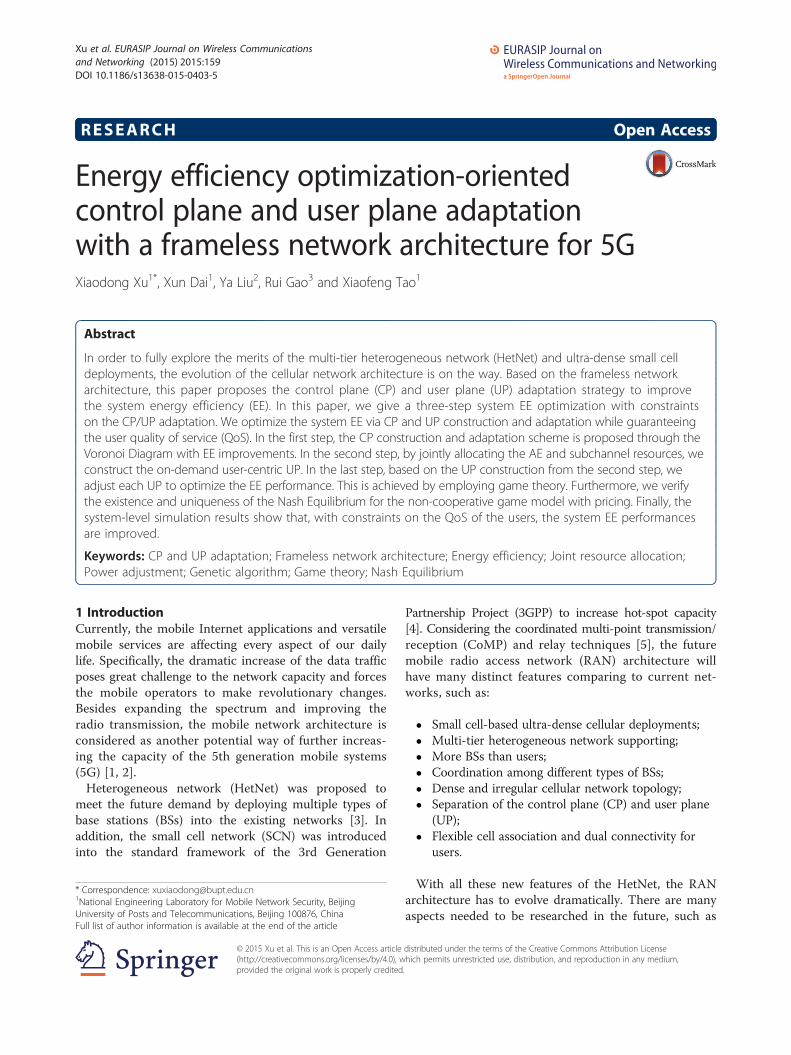
Xu et al. EURASIP Journal on Wireless Communicationsand Networking (2015) 2015:159 DOI 10.1186/s13638-015-0403-5
RESEARCH Open Access
Energy efficiency optimization-orientedcontrol plane and user plane adaptationwith a frameless network architecture for 5G
Xiaodong Xu1*, Xun Dai1, Ya Liu2, Rui Gao3 and Xiaofeng Tao1Abstract
In order to fully explore the merits of the multi-tier heterogeneous network (HetNet) and ultra-dense small celldeployments, the evolution of the cellular network architecture is on the way. Based on the frameless networkarchitecture, this paper proposes the control plane (CP) and user plane (UP) adaptation strategy to improvethe system energy efficiency (EE). In this paper, we give a three-step system EE optimization with constraintson the CP/UP adaptation. We optimize the system EE via CP and UP construction and adaptation while guaranteeingthe user quality of service (QoS). In the first step, the CP construction and adaptation scheme is proposed through theVoronoi Diagram with EE improvements. In the second step, by jointly allocating the AE and subchannel resources, weconstruct the on-demand user-centric UP. In the last step, based on the UP construction from the second step, weadjust each UP to optimize the EE performance. This is achieved by employing game theory. Furthermore, we verifythe existence and uniqueness of the Nash Equilibrium for the non-cooperative game model with pricing. Finally, thesystem-level simulation results show that, with constraints on the QoS of the users, the system EE performancesare improved.
Keywords: CP and UP adaptation; Frameless network architecture; Energy efficiency; Joint resource allocation;Power adjustment; Genetic algorithm; Game theory; Nash Equilibrium
1 IntroductionCurrently, the mobile Internet applications and versatilemobile services are affecting every aspect of our dailylife. Specifically, the dramatic increase of the data trafficposes great challenge to the network capacity and forcesthe mobile operators to make revolutionary changes.Besides expanding the spectrum and improving theradio transmission, the mobile network architecture isconsidered as another potential way of further increas-ing the capacity of the 5th generation mobile systems(5G) [1, 2].Heterogeneous network (HetNet) was proposed to
meet the future demand by deploying multiple types ofbase stations (BSs) into the existing networks [3]. Inaddition, the small cell network (SCN) was introducedinto the standard framework of the 3rd Generation
* Correspondence: [email protected] Engineering Laboratory for Mobile Network Security, BeijingUniversity of Posts and Telecommunications, Beijing 100876, ChinaFull list of author information is available at the end of the article
© 2015 Xu et al. This is an Open Access article(http://creativecommons.org/licenses/by/4.0), wprovided the original work is properly credited
Partnership Project (3GPP) to increase hot-spot capacity[4]. Considering the coordinated multi-point transmission/reception (CoMP) and relay techniques [5], the futuremobile radio access network (RAN) architecture willhave many distinct features comparing to current net-works, such as:
� Small cell-based ultra-dense cellular deployments;� Multi-tier heterogeneous network supporting;� More BSs than users;� Coordination among different types of BSs;� Dense and irregular cellular network topology;� Separation of the control plane (CP) and user plane
(UP);� Flexible cell association and dual connectivity for
users.
With all these new features of the HetNet, the RANarchitecture has to evolve dramatically. There are manyaspects needed to be researched in the future, such as
distributed under the terms of the Creative Commons Attribution Licensehich permits unrestricted use, distribution, and reproduction in any medium,.
Xu et al. EURASIP Journal on Wireless Communications and Networking (2015) 2015:159 Page 2 of 15
the cellular network modeling with dense and irregulardeployments, the influence of separated CP&UP on sys-tem energy efficiency (EE), and so on.Currently, there is significant research on the C-RAN,
Open RAN, Soft Cell, and frameless network architec-ture (FNA) [6–10]. Based on the baseband pool, ChinaMobile Research Institute proposed C-RAN featuring acentralized base band unit, coordination, and cloudcomputing [6]. A software-defined RAN architecture isimplemented through the virtualization in [7]. For theSoft Cell concept proposed in [8], the transparent sets ofBSs are provided for users.Research on the FNA has also been studied substantially.
In [9, 10], the concept of the FNA was given to explore thecapacity gain in the network architecture evolution. Severalimportant metrics, e.g., the user-centric frameless coveragedefinition with coordinated serving set construction,centralized resource management, CP/UP separationand adaptation, were considered and found to supportthe FNA networking. In the FNA, the resource poolingand service slicing schemes are proposed for differentuser quality of service (QoS) guaranteed resource allo-cations. According to the booming and strong re-search conducted in this field, FNA is a promisingsolution for fulfilling the requirements of 5G. Specific-ally, the user-centric service and cloud computing fea-tures are important for managing the multi-tierHetNets.The research topics for the FNA include the network
topology modeling, on-demand user-centric serving setconstruction, CP/UP adaptation, mobility management,and so on. In this paper, we focus on the CP/UP adapta-tion schemes based on the FNA.In mobile networks, 3GPP has already started dis-
cussions on the CP/UP separation. The RAN2 StudyItem - Small Cell Enhancement studies the dual con-nectivity in the small cell scenarios. It allows users toconnect to both small cells and macrocells at thesame time, which can effectively reduce the frequency ofhandovers. Therefore, CP and UP are separated to achievehigh efficiency, flexibility, and low cost. Furthermore,3GPP has designed two alternative architectures for theCP and nine alternative architectures for the UP. In thisscheme, the CP/UP may both be maintained coopera-tively by the macro- and small cells.However, the separation of the CP and UP introduces
new relationship between their coverage areas, whichcould be modeled by constraints on the deployment ofCP and UP. Considering the constraints, the system EEcould be further improved by dynamically adjusting theseparated CP and UP. This method is defined as the CP/UP adaptation. The CP/UP adaptation also raiseschallenges for the AE association on the aforementioneduser connectivity, such as choosing the “best” AE for the
specific user considering both the user QoS requirementand the system EE.In this paper, we present the constraints and adapta-
tion scheme for the CP and UP separation. A three-stepoptimization solution is given. The main contributionsof this paper are highlighted as follows:
� CP/UP separation-based adaptation model isconstructed with constraints.
� The CP construction and adaptation scheme is givenusing the Voronoi Diagram with EE optimization.
� Considering the user QoS requirements, on-demanduser-centric UP construction with joint resourceallocation (AE and subchannel) for establishing theserving set is studied. Equal power allocation for allthe UPs are maintained by the AEs within theserving set. The coordination between the AEs isimplemented for better supporting different userQoS requirements.
� Game theory is employed for power adjustmentbased UP adaptation to achieve the optimal EEperformance. Additionally, we also verified theexistence and uniqueness of the Nash Equilibriumfor the proposed non-cooperative game model.
The structure of this paper is arranged as follows. InSection 2, we give the system model for the FNA andput constraints on the CP/UP. In Section 3, we proposea Voronoi Diagram-based CP construction and adapta-tion for EE optimization. Then, we study the joint allo-cation of the AE and subchannels for UP construction inSection 4 and game theory-based power adjustment forUP adaptation in Section 5. Finally, we give the EEperformance evaluation and simulation of CP/UP adap-tation in Section 6.
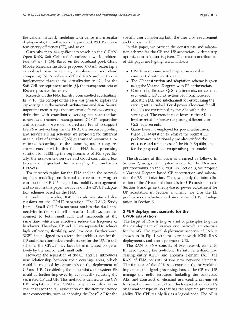
2 FNA deployment scenario for theCP/UP adaptationThe target of FNA is to give a set of principles to guidethe development of user-centric network architecturefor the 5G. The typical deployment scenario of FNA isshown as in Fig. 1 with the core network (CN), RANdeployments, and user equipment (UE).The RAN of FNA consists of two network elements.
By decomposing the traditional BS into centralized pro-cessing entity (CPE) and antenna element (AE), theRAN of FNA consists of two new network elements.The function of the CPE is to maintain the networking,implement the signal processing, handle the CP and UP,manage the radio resources including the connectedAEs, and construct on-demand user-centric serving setfor specific users. The CPE can be located at a macro BSor at another type of BS that has the required processingability. The CPE mainly lies as a logical node. The AE is
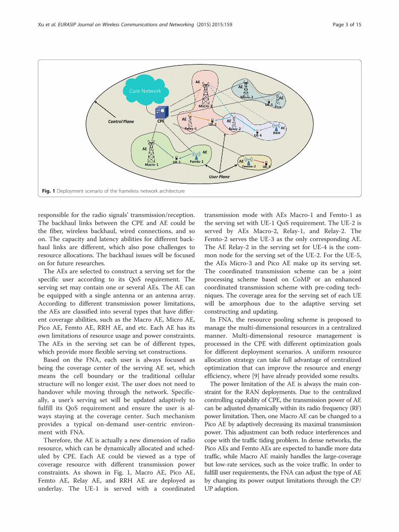
Fig. 1 Deployment scenario of the frameless network architecture
Xu et al. EURASIP Journal on Wireless Communications and Networking (2015) 2015:159 Page 3 of 15
responsible for the radio signals’ transmission/reception.The backhaul links between the CPE and AE could bethe fiber, wireless backhaul, wired connections, and soon. The capacity and latency abilities for different back-haul links are different, which also pose challenges toresource allocations. The backhaul issues will be focusedon for future researches.The AEs are selected to construct a serving set for the
specific user according to its QoS requirement. Theserving set may contain one or several AEs. The AE canbe equipped with a single antenna or an antenna array.According to different transmission power limitations,the AEs are classified into several types that have differ-ent coverage abilities, such as the Macro AE, Micro AE,Pico AE, Femto AE, RRH AE, and etc. Each AE has itsown limitations of resource usage and power constraints.The AEs in the serving set can be of different types,which provide more flexible serving set constructions.Based on the FNA, each user is always focused as
being the coverage center of the serving AE set, whichmeans the cell boundary or the traditional cellularstructure will no longer exist. The user does not need tohandover while moving through the network. Specific-ally, a user’s serving set will be updated adaptively tofulfill its QoS requirement and ensure the user is al-ways staying at the coverage center. Such mechanismprovides a typical on-demand user-centric environ-ment with FNA.Therefore, the AE is actually a new dimension of radio
resource, which can be dynamically allocated and sched-uled by CPE. Each AE could be viewed as a type ofcoverage resource with different transmission powerconstraints. As shown in Fig. 1, Macro AE, Pico AE,Femto AE, Relay AE, and RRH AE are deployed asunderlay. The UE-1 is served with a coordinated
transmission mode with AEs Macro-1 and Femto-1 asthe serving set with UE-1 QoS requirement. The UE-2 isserved by AEs Macro-2, Relay-1, and Relay-2. TheFemto-2 serves the UE-3 as the only corresponding AE.The AE Relay-2 in the serving set for UE-4 is the com-mon node for the serving set of the UE-2. For the UE-5,the AEs Micro-3 and Pico AE make up its serving set.The coordinated transmission scheme can be a jointprocessing scheme based on CoMP or an enhancedcoordinated transmission scheme with pre-coding tech-niques. The coverage area for the serving set of each UEwill be amorphous due to the adaptive serving setconstructing and updating.In FNA, the resource pooling scheme is proposed to
manage the multi-dimensional resources in a centralizedmanner. Multi-dimensional resource management isprocessed in the CPE with different optimization goalsfor different deployment scenarios. A uniform resourceallocation strategy can take full advantage of centralizedoptimization that can improve the resource and energyefficiency, where [9] have already provided some results.The power limitation of the AE is always the main con-
straint for the RAN deployments. Due to the centralizedcontrolling capability of CPE, the transmission power of AEcan be adjusted dynamically within its radio frequency (RF)power limitation. Then, one Macro AE can be changed to aPico AE by adaptively decreasing its maximal transmissionpower. This adjustment can both reduce interferences andcope with the traffic tiding problem. In dense networks, thePico AEs and Femto AEs are expected to handle more datatraffic, while Macro AE mainly handles the large-coveragebut low-rate services, such as the voice traffic. In order tofulfill user requirements, the FNA can adjust the type of AEby changing its power output limitations through the CP/UP adaption.

Xu et al. EURASIP Journal on Wireless Communications and Networking (2015) 2015:159 Page 4 of 15
The CP/UP is separated in the FNA. Based on the cen-tralized resource management, the CP and UP are bothmaintained by the CPE. The CP needs to cover all thedeployment area for supporting all possible user accessrequests and other necessary signaling processes. Inorder to cover a relatively large area, the CP is usuallyhandled by the Macro AEs with higher power limita-tions, which are logically named as the Controlling-AEs.The AEs are defined as Data-AEs, when they make upthe UP as an on-demand user-centric serving set. TheData-AEs only need to cover the required area for thespecific user. The beamforming or pre-coding tech-niques with multiple AEs can also be implemented forfurther improving the capacity and decreasing the inter-ferences. The UPs are also constrained and controlled bythe CPE, which could be adjusted adaptively for bettersystem performances.In this paper, we will give the CP/UP adaptation
scheme for improving the system EE performance in thedownlink scenario of the FNA networks. A three-stepEE optimization process is designed as follows.
3 CP construction and adaptation withVoronoi DiagramIn the FNA, the coordinated transmission is managedby one CPE with an arbitrary deployment of AEswithin the coverage area. The CP and UP are separatedbased on the FNA. The designated Controlling-AEimplements the function of CPE, which is handlingand maintaining the control plane. The Data-AEsmaintain their own user plane under the control ofControlling-AEs.The Data-AEs distributed within the coverage area of
a Controlling-AE are supposed to be managed by theControlling-AE through the CPE. To quantize themaster–slave relationship between the Controlling-AEand Data-AE, we focus on a simplified scenario that in-cludes a single Controlling-AE and multiple relatedData-AEs. For notational simplicity, the Controlling-AE is denoted as AE 0 while Data-AEs are denotedas AE i (i = 1, ⋯, N). We denote Pi as the maximumtransmission power of the ith AE, Pc, Po as the allocatedtransmission power for CP and UP of the Controlling-AE,which satisfy the constraints that pc ≤ po, po ≤ po. For theData-AE, the constraints should be pi ≤ pi(i = 1, …, N),where pi denotes the allocated transmission power of theith Data-AE for the UP. Since the CP transmits thenecessary signaling for the UP, additional coverage con-straints should be made for the UP. That is, the wholecoverage of all the UPs constructed by the Data-AEsshould not surpass the coverage of the CP. Then theabove constraint can be transformed as the coverageradius of Data-AE:
di þ ri ≤ r0 ð1Þwhere di is the distance between the Controlling-AE andith Data-AE. ri is the coverage radius of the ith Data-AE,and ro is the coverage radius of the Controlling-AE. Thecoverage radius of the ith Data-AE ri is actually deter-mined by its transmission power pi, while the coverageradius of the Controlling-AE ro is determined by its CPtransmission power pc. Then, Equation 1 can be furthertransformed to a power constraint of ith Data-AE:
pi ≤ pc − P dið Þ; i ∈ 1;⋯;Nf g ð2ÞWhere P(di) is the power attenuation from the ith Data-AE to the Controlling-AE. The above power constraintstill guarantees that the coverage of UPs does not sur-pass the CP coverage, which will be used in the UP con-struction step of Section 4.In order to formulate the above constraints, a basic
signal propagation model capturing pathloss as well asshadowing is defined as [11]:
prx ¼ Krro
� �−α
φPtx ð3Þ
Where Prx, Ptx, r, and α denote the receiving power,transmission power, propagation distance, and pathloss ex-ponent, respectively. The random variable φ is used tomodel slow fading effects and commonly follows a log-normal distribution. K is set to the free-space path gainat distance ro with assumption of omnidirectional an-tennas. Here, the coverage is defined as the maximumcoverage range, which satisfies the UE’s minimum re-quired received power Pmin. The effect of shadowingwill be averaged out for the network planning of theCP construction and adaptation. The coverage radius
can be expressed as ri ¼ roffiffiffiffiffiffiffiffiffiffiffiffiffiffiffiffiffiffiKP=Pmin
αp
.
In the designed three-step EE optimization for the CP/UP adaptation, the first step aims at constructing aseamless deployment of the CP with minimum transmis-sion power. The Voronoi Diagram, a geometric structurein the computational geometry, divides the space into anumber of regions consisting of all the points closer to aspecific site than to any other. As energy consumption isproportional to distance, the Voronoi Diagram also de-fines regions where less energy consumption is required.In order to achieve better EE in the CP construction andadaptation, we construct Voronoi coverage area for theControlling-AEs. The Data-AEs located within theVoronoi coverage area are controlled by the correspond-ing Controlling-AE.As shown in Fig. 2, the deployment of Controlling-
AEs creates a Voronoi tessellation of the CP. Assum-ing that C represents the set of n Controlling-AEs. In2D Euclidean space, dE(ci,x) denotes the Euclidean
Fig. 2 Voronoi tessellation of the CP construction (the blue spots represent the locations of the Controlling-AEs and the red triangles are Data-AEs)
Xu et al. EURASIP Journal on Wireless Communications and Networking (2015) 2015:159 Page 5 of 15
distance between the ith Controlling-AE and a pos-ition x. Therefore, the Voronoi coverage of the ithControlling-AE is defined as
Vor cið Þ ¼ x ∈ R2 ∀j ≠ i; dE ci; xð Þ < dE cj; x� ��� � ð4Þ
In order to further adapt the transmission powerof Controlling-AE with updated AE deployment orcoverage area, the Voronoi coverage can be redefinedbased on the pathloss between the Controlling-AE andpoint x. Let α(ci,x)t be the pathloss between the ithControlling-AE and the position x at time slot t, theVoronoi coverage will be revised as
Vor cið Þt ¼ x ∈ R2 ∀j ≠ i; α ci; xð Þt< α cj; x� �
t
�� onð5Þ
Then, the whole CP can be formed into the expres-sion as ∪ 1 ≤ i ≤ nVor(ci). According to this definition,any position in the Voronoi coverage area is closer toits Voronoi Controlling-AE than any others, whichyields less power consumption. As a consequence, the re-quired transmission power for the Controlling-AE isminimized.The simulation evaluation of the proposed CP con-
struction and adaptation could be found in Section 6.
4 User-centric UP construction with joint AE andsubchannel allocationFor the second step of the designed optimizationprocess, the initial deployment of the UP constructionfor each user should be set up with the available sys-tem resources. Based on FNA, AE is released as a new
dimensional radio resource for allocation and scheduling.By jointly allocating the AE and subchannel resources,the on-demand user-centric UP is constructed with theuser’s QoS requirement. The AEs’ transmission powersare allocated equally in this step. Moreover, the trans-mission power will be further adjusted based on gametheory in the third step.
4.1 Joint resource allocation model for theUP constructionAssume that there are N Data-AEs located in the net-work with two types of AEs, including the Macro AEand Small Cell AE. The bandwidth of each AE is thesame and is divided into M subchannels. We set Pi asthe maximum transmission power of the ith Data-AE.Meanwhile, K users are randomly distributed in thecoverage area of the FNA, including K1 users withguaranteed bit rate (GBR) service and K2 users withnon-GBR service. Each subchannel of an AE can onlybe allocated to one user. That is, we do not consider aspace division multiple access (SDMA) scenario.According to the concepts of FNA, in order to
reduce the inter-AE interference and improve the cap-acity performance, users can use coordination tech-niques to receive signals from more than one AE inthe same time slot. Let Am
k represent the serving set ofuser k on subchannel m, while �Am
k is the complementset of Am
k . The instantaneous received signal to inter-ference and noise ratio (SINR) on subchannel m foruser k is given by:
Xu et al. EURASIP Journal on Wireless Communications and Networking (2015) 2015:159 Page 6 of 15
γmk ¼P
i∈Amkpi h
mi;k
2Pj∈Am
k�pj h
mj;k
2 þ nmk
ð6Þ
where hmi;k denotes the complex channel responsebetween AE i and user k on subchannel m, nmk denotesthe additive white Gaussian noise with covariance σ2 andpi is the transmission power of AE i to the serving user.The transmission powers for the AEs are allocated to itsserving users equally in this step for decreasing thecomplexity of the multi-dimensional joint resource allo-cations. The power adjustment for the UP adaptationwill be conducted further in the last optimization step.The data rate allocated to user k on subchannel m can
be calculated as [12]:
Rmk ¼ Blog2 1þ γmk
� � ð7Þ
The subchannel set allocated to user k is denoted asSk ⊆ {0, 1, 2, ⋯, M}, ∀ k, and we assume that at mostNS subchannels can be assigned to one user. Thus, it isobvious that |Sk| ≤ Ns, ∀ k, where “||” denotes the cardin-ality of the set. We assume that the serving set for user kon all subchannels in Sk is selected form a common AEset. Ak ⊆ {0, 1, 2, ⋯, N + 1}, ∀ k, i.e., Am
k ⊆Ak ;∀m∈Sk ;∀k. That is, Am
k may contain all elements or partialelements in Ak. Assume that the maximal number ofelements in Ak is Na, i.e., |Ak| ≤ Na, ∀ k.Hence, the instantaneous data rate for the user k can
be given by:
Rk ¼Xm∈Sk
Rmk ð8Þ
In order to quantify the different QoS requirementsof users, the utility theory in economics is introducedto describe the characteristics of service by mappingthe data rate to the user satisfaction level [13].According to the user service QoS constraints, theutility functions of the GBR and non-GBR service areverified as the S-shaped function and convex functioncorrespondingly [13, 14]. To satisfy these two types ofservices simultaneously, the utility function U(r) of alltypes of service is extracted from [15].
U rð Þ ¼ EAþ Be−C r−dð Þ þ D ð9Þ
where r is the data rate allocated to user; R is the totalresource of the system; C mainly influences the slope ofthe curve; A, B, D, E mainly effect the range of utilityvalue; and d is the inflection point of the utilityfunction, which indicates the user requirement of re-source. By setting different parameter values, theutility function can present different characteristics,
both the S-shaped function and the convex function.The utility functions of the GBR service Ureal(r) and non-GBR service Unon-real(r) are obtained from Equation 9 [15].The system utility is defined as the linear weighted
sum of all users’ utility values. In Equation 10, λ rep-resents the priority of GBR service and μ representthe priority of non-GBR service. These two weightsare constrained by λ, μ ∈ [0, 1] and λ + μ = 1.
U system ¼ λXk1k¼1
U real rkð Þ þ μXk1þk2
k¼K1þ1
Unon‐real rkð Þ ð10Þ
The system utility can be further extended to in-clude more types of service. Since the utility valuerepresents the satisfaction level of users, the systemutility indeed represents all users’ satisfaction level,which can provide a better reflection of system per-formance than throughput.
4.2 Generic algorithm-based centralized resourceallocationIn the FNA, the UP construction process is jointly andsimultaneously allocating two dimensions of resources(AEs and subchannels) to users with different QoSrequirements. Such a multi-dimensional resource alloca-tion problem can be solved by using the resourcepooling-based centralized RRM scheme [9]. The abovescheme is processed by the CPE to manage all of theavailable resources uniformly. Since the optimizationproblem of centralized resource allocation has a largeand complex search space, genetic algorithm (GA) isimplemented to obtain near-optimal solutions with arelatively fast convergence speed.Based on GA, chromosome, which is a two-dimensional
integer matrix, is used to represent the potential resourceallocation solution. Each row of the matrix represents theresource allocation strategy for the specific user. More-over, each row can be further divided into several parts.Each part lists the allocated elements of a particular di-mension of resource. In particular, the chromosome G inthe following GA process is given by:
G ¼
a1;1; a1;2;⋯; a1;Na ; b1;1; b1;2;⋯; b1;Ns;⋯⋯
aK1;1; aK 1;2;⋯; aK 1;Na ; bK 1;1; bK1;2;⋯; bK 1;Ns ;aK 1þ1;1; aK 1þ1;2;⋯; aK 1þ1;Na ; bK 1þ1;1; bK 1þ1;2;⋯; bK1þ1;Ns ;
⋯⋯aK1þK2;1; aK1þK2;2;⋯; aK 1þK 2;Na ; bK 1þK 2;1; bK1;K 2;2;⋯; bK 1þK 2;Ns ;
8>>>>>><>>>>>>:
ð11Þwhere the first K1 rows represent the resource allocationstrategies of the K1 users with GBR service, and theremaining K2 rows represent the resource allocationstrategies of the users with the non-GBR services. Eachrow is further divided into two parts. The first part
Xu et al. EURASIP Journal on Wireless Communications and Networking (2015) 2015:159 Page 7 of 15
containing Na integers indicates the allocated AEs, whilethe second part containing Ns integers lists the allocatedsubchannels. The initial population which includes Np
chromosomes is generated by a random process.Fitness function is constructed by the system utility
function, which is the sum of all users’ utility values. Itcan be used to evaluate the chromosomes. The largerthe fitness value is, the better the solution is. Thus, theoptimized objective is to maximize the fitness value thatis to maximize the system utility. Since the utility valuerepresents the satisfaction level of user, the proposed al-gorithm tends to meet the requirements of two types ofservices simultaneously under the three constraints inthe user-centric UP constructions process. Specifically,we assume that at most Na out of N AEs and Ns out ofM subchannels can be allocated to user k. In addition toAE and subchannel limitations, we also apply the con-straint derived from Equation 2 into the power limita-tion where we choose the minimum value between thetwo power constraints Pi (maximum transmission powerlimitation) and pc-P(di). By using such constraint, we areable to guarantee that the coverage of UPs will not sur-pass the CP coverage required in Section 3.
maxF ¼ maxU system
¼ max λXK1
k¼1
U real rkð Þ þ μXK1þK2
k¼K1þ1
Unon‐real rkð Þ" #
ð12Þs.t.
Akj j ≤ Na; Ak ⊆ 0; 1; 2;⋯;Nf g;∀kSkj j ≤ Ns; Sk ⊆ 0; 1; 2;⋯;Mf g;∀k
pi ≤ min Pi; Pc − P dið Þf g; i∈ 1; 2;⋯;Nf gThe chromosomes will be passed to the next gener-
ation through a four-step breeding process includingSelection, Crossover, Mutation, and Modification.First of all, a pair of parent individuals is selected
based on the so-called “Roulette Wheel Selection”, suchthat the higher the fitness, the greater the opportunityfor the individual to be selected. The possibility ofchromosome Gi being selected is:
p Gið Þ ¼ F Gið ÞXNp
k¼1F Gkð Þ
ð13Þ
Where F(Gi) is the value of the fitness function ofchromosome Gi. Note that the selected chromosomesare still in the population, and as a result, it is entirelylikely that a chromosome is selected more than once.Then, two children are generated by combining their par-
ent’s genes. In particular, a crossover point is first chosenrandomly at a certain column of the two given chromo-somes. Next, in order to form the first offspring, all the row
vectors before the crossover point of the first matrix willcombine with the row vectors after the crossover point ofthe second matrix. The second offspring is generated in theopposite way. Herein, the crossover process is illustrated.Assume two selected parent individuals A and B as
follows:
A ¼
a1;1; a1;2;⋯; a1;Na ; b1;1; b1;2;⋯; b1;Ns
⋯⋯aK1;1; aK 1;2;⋯; aK1;Na ; bK 1;1; bK1
;2;⋯; bK 1;Ns ;aK1þ1;1; aK 1þ1;2;⋯; aK 1þ1;Na ; bK1þ1;1; bK1þ1;2;⋯; bK1þ1;Ns ;
⋯⋯aK1þK2 ; aK 1þK 2;2;⋯; aK1þK 2Na ; bK1þK2;1; bK 1þK2;2;⋯; bK 1þK 2;Ns ;
8>>>>>>><>>>>>>>:
ð14Þ
B ¼
a′1;1; a′1;2;⋯; a′1;Na
; b′1;1; b′1;2;⋯; b′1;Ns
;
⋯⋯a′K 1;1; a
′K 1;2;⋯; a′K1;Na
; b′K1;1; b′K 1;2;⋯; b′K1;Ns
;
a′K 1;1; a′K 1;2;⋯; a′K1;Na
; b′K 1þ1;1; b′K1þ1;2;⋯; b′K 1þ1;Ns
;⋯⋯
a′K1þK2;1; a′K 1þK2;2;⋯; a′K 1þK 2;Na
; b′K 1þK 2;2; b′K1þK2;2;⋯; b′K 1þK 2;Ns
;
8>>>>>>>><>>>>>>>>:
ð15ÞSuppose that the crossover point is located between
b1,1 and b1,2. Then the two children chromosomes C andD can be expressed as:
C ¼
a1;1; a1;2;⋯; a1;Na ; b1;1; b′1;2;⋯; b′1;Ns
;⋯⋯
aK 1þ1; aK1;2;⋯; aK1;Na ; bK 1;1; b′K 1;2;⋯; b′K1;Ns
;
aK 1þ1;1; aK1þ1;2;⋯; aK 1þ1;Na ; bK1þ1;1; b′K 1þ1;2;⋯; b′K1þ1;Ns
;⋯⋯
aK 1þK 2;1; aK 1þK 2;2⋯; aK1þK2;Na ; bK 1þK 2;1; b′K 1þK 2;2;⋯; b′K1þK2;Ns
;
8>>>>>>><>>>>>>>:
ð16Þ
D ¼
a′1;1; a′1;2;⋯; a′1;Na
; b′1;1; b1;2;⋯; b1;Ns;⋯⋯
a′K1;1; a′K1;2;⋯; a′K 1;Na
; b′K1;1; bK1 ;2;⋯; bK1;Ns ;
a′K 1þ1;1; a′K 1þ1;2;⋯; a′K 1;Na
; b′K1;1; bK1 ;2;⋯; bK1;Ns ;⋯⋯
a′K1þK 2;1; a′K 1þK 2;2;⋯; a′K1þK 2Na
; b′K 1þK 2;1; bK 1þK 2;2;⋯; bK1þK 2;Ns ;
8>>>>>>><>>>>>>>:
ð17ÞIn this way, the offsprings are expected to provide better
chromosomes with their parents’ partial characteristics.After the above processes, all of the children will go
through the mutation operation to avoid converging to alocal optimized solution. Since the individuals generatedby crossover and mutation may no longer satisfy systemconstraints, some modification should be made.Finally, in order to prevent good solutions from being
lost in the breeding process and to ensure the conver-gence of the algorithm, we take the two best solutions(named “Elites”) from the parent generation and directthem into the child generation. Meanwhile, all other par-ents will be replaced by the offspring generation. Thenew generation will replace the original generation andthe above procedures are repeated for a total of Ng
Xu et al. EURASIP Journal on Wireless Communications and Networking (2015) 2015:159 Page 8 of 15
times. The whole population will evolve from generationto generation and gradually converge to the optimizedsolution. When the algorithm is terminated, the central-ized resource allocation solution is based on the best in-dividual Gbest t among the current population.Using the joint resource allocation strategy of AEs and
subchannels in the Gbest, the UP is constructed with equaltransmission power allocation mentioned before, where thetransmission power of each serving set Data-AE is Pi, i ∈{1, 2, ⋯, N}. After that, based on the UP construction pa-rameters, the UP adaptation via a power adjustmentscheme can be implemented to further optimize the EEperformance.
5 UP adaptation with game theory-based poweradjustmentBased on above CP and UP construction, game theorycould be further implemented as a power adjustmentstrategy for the UP adaptation in order to maximize thesystem EE. The non-cooperative game model with thepricing function is used to achieve the optimized systemEE for the Data-AEs. Here, penalty is defined as the ex-cessive power consumption from Macro Data-AEs,which yields severe interferences. The existence anduniqueness of the Nash Equilibrium for the proposedgame model will also be verified.
5.1 Game theory model for the UP adaptationAs we assumed above, the FNA network consists of N1
Macro Data-AEs and N2 Small Cell Data-AEs. One Data-AE is able to serve several users within its coverage area. Itis assumed that there is only one scheduled active user ineach serving set during each signaling slot. Let k ∈{1, 2, ⋯, N} denote the scheduled user k. According tothe results of Gbest and pi, i ∈ {1, 2, ⋯, N} derived inthe UP construction step, the received SINR on subchannelm for the scheduled user k can be expressed as:
γmk ¼X
i∈Amk
pi hmi;k
2Xj∈Am
k�pj h
mj;k
2 þ nmk
ð18Þ
where γk ¼ γmk and pk ¼X
i∈Amk
pi are the aggregate
SINR and transmission power of the scheduled user k,respectively. Considering the user k’s QoS requirement,its received SINR has the constraint as γk≥γ
thresholdk . But
the threshold γthresholdk for GBR service and non-GBRservice are different.
5.2 UP adaption based on game theoryThe UP Adaption focuses on the transmission power ofserving set Data-AEs. Based on the game theory, wepropose a power adjustment scheme for the system EE
optimization from the perspective of Data-AEs. EachData-AE within the serving set will choose a reasonabletransmission power to maximize its own utility of EE per-formance, which is a typical non-cooperative N-playergame problem. Let G = [N, {pk}, {uk(pk, γk|P‐ k)}] denotethe Non-cooperative Power adjustment Game with Pri-cing (NPGP), where
� N = {1, 2, …, N} is the index of the serving setData-AE.
� {pk} = {pk|pk ∈ [0, pmax]} are the transmission powerof serving set Data-AEs for user k and pmax > 0 isthe maximum power constraint of the correspondingData-AEs.
Let {uk(pk, γk|p‐ k) denote the utility of the scheduleduser k, where γk and pk is the aggregated SINR andtransmission power of the user k respectively. p-k is thevector of transmission power of all serving set Data-AEsother than the serving set Data-AEs for user k.Considering the energy efficiency measured in bit/
Joule [16], the utility function of the serving set Data-AEs for user k is defined as:
uk�pk ; γk p‐kj Þ ¼ ak
f γk� �pk
−bkpk ð19Þ
where akf γkð Þpk
denotes the EE of the user k and bkpk de-
notes the linear pricing for the user k. Both the ak andbk are positive factors.f(γk) is defined as:
f γk� � ¼ 1−e−
γk2 ð20Þ
which means that the revenue of the user k will increaseslowly as γk increases [17].The pricing bkpk will ensure that the serving set
Data-AEs for the user k could be penalized when theycause serious interference to other users with moretransmission powers.Finally, the EE optimization problem for the UP adap-
tion is formulated as the game model:
max0≤pk≤pmax
uk pk ; γk p‐kj Þ; ∀k ¼ 1; 2;…;N� ð21Þ
5.3 Nash Equilibrium for the power adjustment gameThe Nash Equilibrium is a steady state that offers apredictable outcome of a game, where Data-AEs com-pete with selfish actions through self-optimization andconverge to a point that no Data-AEs wish to deviateunilaterally. For the proposed game model (21), theNash Equilibrium is defined as:Definition 1:

Xu et al. EURASIP Journal on Wireless Communications and Networking (2015) 2015:159 Page 9 of 15
Suppose p�k ; ∀k ¼ 1; 2;…;N is a solution for (21).Hence, the point p* is a Nash Equilibrium for the pro-posed non-cooperative game if for any p, the followingconditions are satisfied:
uk pk�; γk
� p−k�j Þ≥uk pk ; γk p−kj Þ; ∀k ¼ 1; 2;…;N
��ð22Þ
The proposed game model with pricing in this paperis a supermodular game [18]. The existence and unique-ness of the Nash Equilibrium will be verified as follows.(1) Existence of Nash EquilibriumTheorem 1:The set of Nash Equilibria of a supermodular game is
nonempty. Furthermore, the Nash set has a largest elem-ent and a smallest element.A proof of the theorem can be found in [19]. Let E de-
note the set of Nash Equilibria. Let pS and pL denote thesmallest and the largest elements of E respectively. Thetheorem states that all the equilibria p ∈ E are locatedsuch that pS < p < pL.We introduce a totally asynchronous algorithm that
generates a sequence of powers that converges to thesmallest Nash Equilibrium pS. Suppose that the servingset Data-AEs for user k update their power at time in-stances given by the set Tk = {tk1, tk2, tk3, …} where tkl <tk(l + 1) and for tk0 = 0 all k. Define T = {τ1, τ2, τ3, …} asthe set of update instances T1 ∪ T2 ∪ … ∪ TN sorted inincreasing order. Assume that there are no two time in-stances in set T that are exactly the same. The algo-rithm for finding the Nash Equilibrium is designed asfollows.
Algorithm 1:Let us consider the proposed non-cooperative power
adjustment game with pricing as given in (21). We willgenerate a sequence of the transmission powers:
1) Set the initial power vector at time t = 0: p = p(0).Also let l = 1.
2) For all l such that τl ∈ T
For all serving set Data-AEs for the user k such thatτl ∈ Tki. Given p(τl − 1), compute pk * = arg max uk(pk, yk| p− k)ii. If y�k≥y
thresholdk
Then pk tlð Þ ¼ min p�k ; pmax
� �.
elseRemove user k in this iteration and continue thealgorithm in next iteration [20].end For.end For.
Theorem 2:
The proposed Algorithm 1 converges to a Nash Equilib-rium of the NPGP. Furthermore, it is the smallest equilib-rium pS, in the set of Nash Equilibria.The proof can be found in [17], which implies that the
Nash Equilibrium in the proposed NPGP exists and canbe reached from either the top or the bottom of thestrategy space with Algorithm 1. Since we do not knowif there is a unique equilibrium, we compare the equilib-rium in the Nash set E to determine if there exists a sin-gle equilibrium that dominates all other equilibria.Indeed, we can show that pS is the best equilibrium inthe set E.(2) Uniqueness of Nash EquilibriumTheorem 3:If x, y ∈ E are two Nash Equilibria in NPGP and x ≥ y,
then uk(x) ≤ uk(y) for all k.Proof:
Notice that, for fixed pk, the utility uk ¼ akf γkð Þpk
−bkpkdecreases with increasing p-k for all k. Therefore, sincex− k ≥ y− k, we have:
uk xk ; x−kð Þ≤ xk ; y‐kð Þ ð23ÞAlso, by definition of Nash Equilibrium and since y is
a Nash Equilibrium of NPGP, we have:
uk xk ; y−kð Þ≤uk yk ; y−k� � ð24Þ
By the above equations,
uk xð Þ≤uk yð Þ ð25ÞAccording to the Theorem 3, we know that smaller
Nash Equilibrium leads to higher utilities for all users.Since pS < p for all p ∈ E, we conclude that for all p ∈ E,
uk psð Þ≥uk pð Þ for all k ð26ÞThis result implies that, in case the NPGP has Nash
Equilibria, the one that yields highest utilities is the NashEquilibrium with the minimum total transmission powers.In conclusion, the existence and the uniqueness of the
Nash Equilibrium for the proposed NPGP have beenproved. It means that the transmission power of the serv-ing set Data-AEs at the Nash Equilibrium are regarded asa reasonable solution for the EE improvement of the UPadaption scheme.
6 Simulation evaluationsIn this section, the system-level simulations are conductedto evaluate the proposed CP/UP adaptation scheme. Thesimulation environment is introduced at first with thesimulation parameters. Then, the EE performance of theVoronoi Diagram-based CP construction and adaptationis given. Based on the CP construction, the simulation re-sults of the user-centric UP construction with joint AE
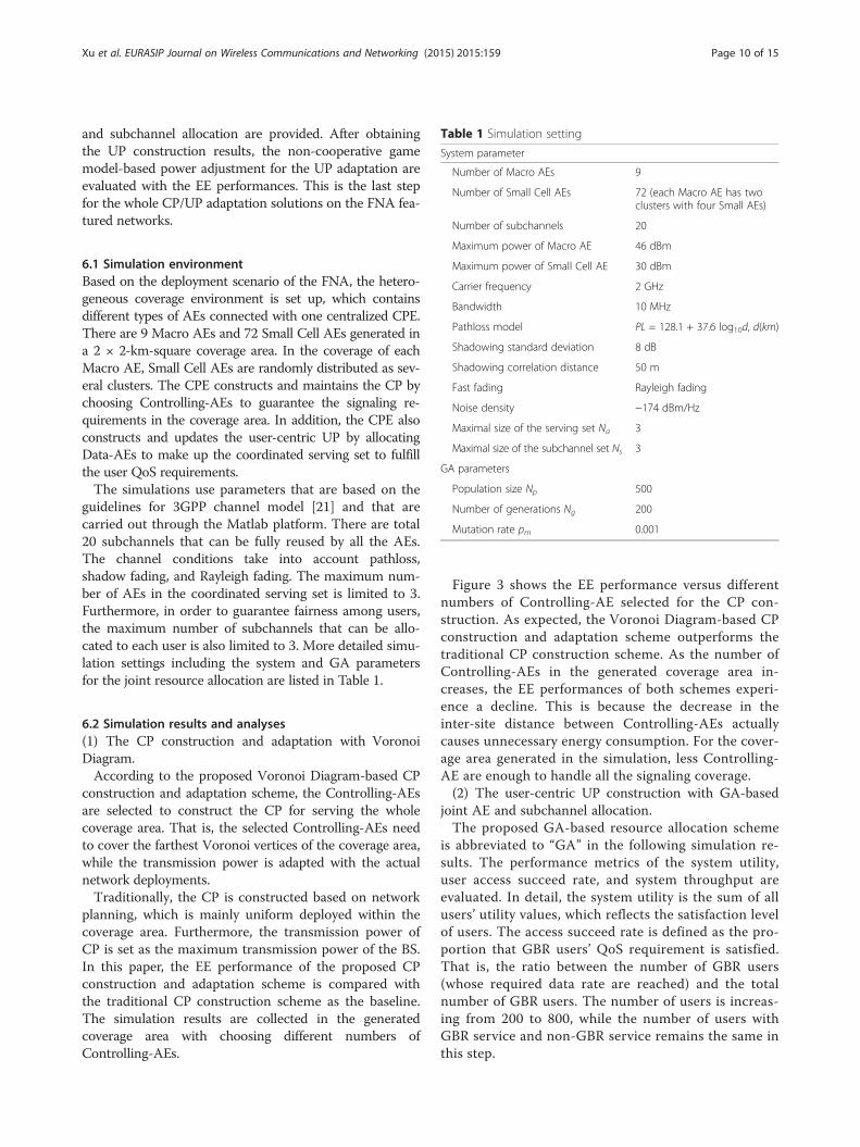
Table 1 Simulation setting
System parameter
Number of Macro AEs 9
Number of Small Cell AEs 72 (each Macro AE has twoclusters with four Small AEs)
Number of subchannels 20
Xu et al. EURASIP Journal on Wireless Communications and Networking (2015) 2015:159 Page 10 of 15
and subchannel allocation are provided. After obtainingthe UP construction results, the non-cooperative gamemodel-based power adjustment for the UP adaptation areevaluated with the EE performances. This is the last stepfor the whole CP/UP adaptation solutions on the FNA fea-tured networks.
Maximum power of Macro AE 46 dBm
Maximum power of Small Cell AE 30 dBm
Carrier frequency 2 GHz
Bandwidth 10 MHz
Pathloss model PL = 128.1 + 37.6 log10d, d(km)
Shadowing standard deviation 8 dB
Shadowing correlation distance 50 m
Fast fading Rayleigh fading
Noise density −174 dBm/Hz
Maximal size of the serving set Na 3
Maximal size of the subchannel set Ns 3
GA parameters
Population size Np 500
Number of generations Ng 200
Mutation rate pm 0.001
6.1 Simulation environmentBased on the deployment scenario of the FNA, the hetero-geneous coverage environment is set up, which containsdifferent types of AEs connected with one centralized CPE.There are 9 Macro AEs and 72 Small Cell AEs generated ina 2 × 2-km-square coverage area. In the coverage of eachMacro AE, Small Cell AEs are randomly distributed as sev-eral clusters. The CPE constructs and maintains the CP bychoosing Controlling-AEs to guarantee the signaling re-quirements in the coverage area. In addition, the CPE alsoconstructs and updates the user-centric UP by allocatingData-AEs to make up the coordinated serving set to fulfillthe user QoS requirements.The simulations use parameters that are based on the
guidelines for 3GPP channel model [21] and that arecarried out through the Matlab platform. There are total20 subchannels that can be fully reused by all the AEs.The channel conditions take into account pathloss,shadow fading, and Rayleigh fading. The maximum num-ber of AEs in the coordinated serving set is limited to 3.Furthermore, in order to guarantee fairness among users,the maximum number of subchannels that can be allo-cated to each user is also limited to 3. More detailed simu-lation settings including the system and GA parametersfor the joint resource allocation are listed in Table 1.
6.2 Simulation results and analyses(1) The CP construction and adaptation with VoronoiDiagram.According to the proposed Voronoi Diagram-based CP
construction and adaptation scheme, the Controlling-AEsare selected to construct the CP for serving the wholecoverage area. That is, the selected Controlling-AEs needto cover the farthest Voronoi vertices of the coverage area,while the transmission power is adapted with the actualnetwork deployments.Traditionally, the CP is constructed based on network
planning, which is mainly uniform deployed within thecoverage area. Furthermore, the transmission power ofCP is set as the maximum transmission power of the BS.In this paper, the EE performance of the proposed CPconstruction and adaptation scheme is compared withthe traditional CP construction scheme as the baseline.The simulation results are collected in the generatedcoverage area with choosing different numbers ofControlling-AEs.
Figure 3 shows the EE performance versus differentnumbers of Controlling-AE selected for the CP con-struction. As expected, the Voronoi Diagram-based CPconstruction and adaptation scheme outperforms thetraditional CP construction scheme. As the number ofControlling-AEs in the generated coverage area in-creases, the EE performances of both schemes experi-ence a decline. This is because the decrease in theinter-site distance between Controlling-AEs actuallycauses unnecessary energy consumption. For the cover-age area generated in the simulation, less Controlling-AE are enough to handle all the signaling coverage.(2) The user-centric UP construction with GA-based
joint AE and subchannel allocation.The proposed GA-based resource allocation scheme
is abbreviated to “GA” in the following simulation re-sults. The performance metrics of the system utility,user access succeed rate, and system throughput areevaluated. In detail, the system utility is the sum of allusers’ utility values, which reflects the satisfaction levelof users. The access succeed rate is defined as the pro-portion that GBR users’ QoS requirement is satisfied.That is, the ratio between the number of GBR users(whose required data rate are reached) and the totalnumber of GBR users. The number of users is increas-ing from 200 to 800, while the number of users withGBR service and non-GBR service remains the same inthis step.

Fig. 3 Energy efficiency of the CP construction and adaptation
Xu et al. EURASIP Journal on Wireless Communications and Networking (2015) 2015:159 Page 11 of 15
During the simulations, two algorithms are used as thecomparisons. One is the pathloss-based AE selection forthe user-centric serving set construction and random-ized subchannel set allocation (abbreviate to “PL-Ran-dom”). Each user will select Na best AEs with the lowestpathloss between the AEs and the user. Then the userwill be randomly allocated the common available sub-channels of all the AEs in the serving set.The other compared algorithm is the pathloss-based
user-centric serving set construction and maximumSINR subchannel set allocation (abbreviate to “PL-Max-SINR”). Each user will select Na best AEs with the lowestpathloss between the AEs and the user. Then the userwill be allocated the common available subchannels of theselected AEs, which tend to provide the highest SINR.The simulation results of the system utility, the user
access succeed rate, and the system throughput are plot-ted as Figs. 4, 5 and 6, respectively.As shown in Fig. 4, the performance of the proposed
UP construction scheme is shown in terms of the systemutility value versus the number of users. It is observedthat the GA-based scheme achieves the highest systemutility value, PL-MaxSINR ranks second and PL-Randomhas the lowest performance. Note that the performance gapbetween GA and other algorithms becomes larger as thenumber of users increases. This is mainly because when theresources are not sufficient, the optimized resource man-agement can allocate limited resources more effectivelybased on different user QoS requirements, which improvesthe system utility further.
For GBR users, the satisfaction level can be measuredby access succeed rate, the larger the better. For in-stance, the access succeed rate 0.8 means that 80 % ofGBR users’ prescribed QoS requirements are fulfilled.As shown in Fig. 5, the proposed GA-based algorithmcan achieve larger access succeed rate than the other so-lutions (PL-MaxSINR, PL-Random), which means theGA-based scheme tends to guarantee that a highernumber of GBR users will meet the required data rate.This is because the S-shaped utility function curve ofthe GBR service rises rapidly at the required bit rate,and allocating enough resources to the GBR users willhave more contribution to the overall system utility,compared to allocating more resources to the non-real-time services.The system throughput performances of these three
algorithms against the number of users were also simu-lated. In Fig. 6, we can observe that the PL-MaxSINR al-gorithm, which pursues maximal throughput, ranks firstas expected. The GA-based scheme ranks second andalso achieves relative high system throughput. This con-firms that the GA-based scheme can achieve a betterbalance between user satisfaction and system through-put. In other words, it can provide better resourceutilization, while just slightly worse system throughput.Since the computational complexity of the solution to
NP-Hard problems is an important factor for evaluatingits performance, the complexities of the proposed GA-based algorithm and comparison schemes will be ana-lyzed as follows.
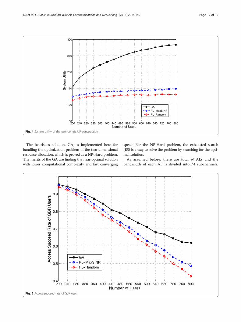
Fig. 4 System utility of the user-centric UP construction
Xu et al. EURASIP Journal on Wireless Communications and Networking (2015) 2015:159 Page 12 of 15
The heuristics solution, GA, is implemented here forhandling the optimization problem of the two-dimensionalresource allocation, which is proved as a NP-Hard problem.The merits of the GA are finding the near-optimal solutionwith lower computational complexity and fast converging
Fig. 5 Access succeed rate of GBR users
speed. For the NP-Hard problem, the exhausted search(ES) is a way to solve the problem by searching for the opti-mal solution.As assumed before, there are total N AEs and the
bandwidth of each AE is divided into M subchannels,
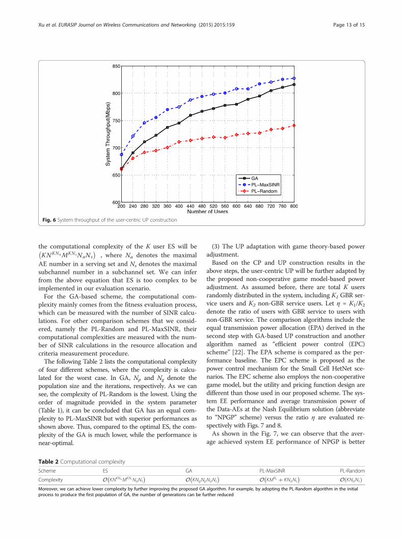
Fig. 6 System throughput of the user-centric UP construction
Xu et al. EURASIP Journal on Wireless Communications and Networking (2015) 2015:159 Page 13 of 15
the computational complexity of the K user ES will beKNKNaMKNsNaNs� �
, where Na denotes the maximalAE number in a serving set and Ns denotes the maximalsubchannel number in a subchannel set. We can inferfrom the above equation that ES is too complex to beimplemented in our evaluation scenario.For the GA-based scheme, the computational com-
plexity mainly comes from the fitness evaluation process,which can be measured with the number of SINR calcu-lations. For other comparison schemes that we consid-ered, namely the PL-Random and PL-MaxSINR, theircomputational complexities are measured with the num-ber of SINR calculations in the resource allocation andcriteria measurement procedure.The following Table 2 lists the computational complexity
of four different schemes, where the complexity is calcu-lated for the worst case. In GA, Np and Ng denote thepopulation size and the iterations, respectively. As we cansee, the complexity of PL-Random is the lowest. Using theorder of magnitude provided in the system parameter(Table 1), it can be concluded that GA has an equal com-plexity to PL-MaxSINR but with superior performances asshown above. Thus, compared to the optimal ES, the com-plexity of the GA is much lower, while the performance isnear-optimal.
Table 2 Computational complexity
Scheme ES GA
Complexity O KNKNaMKNsNaNs� � O KNgNp
�Moreover, we can achieve lower complexity by further improving the proposed GAprocess to produce the first population of GA, the number of generations can be fu
(3) The UP adaptation with game theory-based poweradjustment.Based on the CP and UP construction results in the
above steps, the user-centric UP will be further adapted bythe proposed non-cooperative game model-based poweradjustment. As assumed before, there are total K usersrandomly distributed in the system, including K1 GBR ser-vice users and K2 non-GBR service users. Let η = K1/K2
denote the ratio of users with GBR service to users withnon-GBR service. The comparison algorithms include theequal transmission power allocation (EPA) derived in thesecond step with GA-based UP construction and anotheralgorithm named as “efficient power control (EPC)scheme” [22]. The EPA scheme is compared as the per-formance baseline. The EPC scheme is proposed as thepower control mechanism for the Small Cell HetNet sce-narios. The EPC scheme also employs the non-cooperativegame model, but the utility and pricing function design aredifferent than those used in our proposed scheme. The sys-tem EE performance and average transmission power ofthe Data-AEs at the Nash Equilibrium solution (abbreviateto “NPGP” scheme) versus the ratio η are evaluated re-spectively with Figs. 7 and 8.As shown in the Fig. 7, we can observe that the aver-
age achieved system EE performance of NPGP is better
PL-MaxSINR PL-Random
NaNs� O KMNs þ KNaNs
� � O KNaNsð Þalgorithm. For example, by adopting the PL-Random algorithm in the initialrther reduced

The ratio of GBR services and non-GBR services1 2 3 4 5 6 7 8 9 10
Ave
rage
achi
eved
EE
in[b
it/J]
105
106
107
108
NPGP
EPA
EPC
Fig. 7 Average achieved system EE at the Nash Equilibrium
Xu et al. EURASIP Journal on Wireless Communications and Networking (2015) 2015:159 Page 14 of 15
than that for the EPA and EPC schemes. The system EEat the Nash Equilibrium solution of the proposed NPGPis much better than that of EPA at each value of η. Theutility function and pricing function design with theNPGP game model also show the gain of the EE per-formance over the EPC scheme.Figure 8 compares serving set Data-AEs’ average trans-
mission power among the Nash Equilibrium solution ofthe NPGP, EPA, and EPC versus the user ratio η. As
The ratio of GBR service1 2 3 4 5
Ave
rage
tran
smis
sion
pow
erof
Dat
a-A
Es
in[d
Bm
]
10
15
20
25
30
35
40
Fig. 8 Average power of the serving set Data-AEs
observed from the simulations results, the serving setSmall Cell Data-AEs’ average transmission powers atNash Equilibrium are much lower than that of the EPAand EPC with η increasing, which means that the trans-mission power of the Small Cell AEs are saved with theproposed NPGP scheme. For the average transmissionpower of Macro Data-AEs in the serving set, the NPGPat the Nash Equilibrium solution has larger transmissionpower requirements than that of the EPA and EPC
s and non-GBR services6 7 8 9 10
NPGP-Macro Data-AE
NPGP-Small Cell Data-AE
EPA-Macro Data-AE
EPA-Small Cell Data-AE
EPC-Macro Data-AE
EPC-Small Cell Data-AE

Xu et al. EURASIP Journal on Wireless Communications and Networking (2015) 2015:159 Page 15 of 15
scheme. This is due to the fact that the Macro Data-AEneeds to cover the Macro cell edge users to guaranteetheir QoS requirements, especially with the increasing ofGBR services. The users are randomly distributed in thewhole coverage area, which means there are several GBRusers located in the Macro coverage edge. The largertransmission power limitation lets the Macro Data-AEhave the ability to handle the GBR requirements even atthe edge of coverage. There is only about 7 % average in-crease of the Macro Data-AE transmission power com-pared with the NPGP scheme, which is still under thepower limitation of the Macro Data-AE. Furthermore,since the number of Small Cell Data-AEs is much morethan the Macro Data-AEs in the system, it is obviousthat the proposed NPGP-based UP adaptation solutionis helpful to save the transmission power and improvethe system EE.
7 ConclusionsBased on the frameless network architecture, we proposea control plane/user plane adaptation strategy for systemenergy efficiency improvement. The constraints for theCP/UP separation-based adaptation are presented andthe system EE performance optimization problem is de-signed as a three-step scheme. Firstly, the CP is con-structed with the Voronoi Diagram to achieve bettersystem EE. Secondly, we constructed the user-centric UPfor each specific user and considered user-centric serv-ing set construction by jointly allocating resources. TheAEs and subchannels are jointly allocated by the GA al-gorithm with equal power allocations for different QoSservices, while the power adjustments are further han-dled by the third step with game theory solutions for thesystem EE optimization. The non-cooperative power ad-justment game model with pricing is given and thecorresponding Nash Equilibrium is solved with the verifi-cations of its existence and uniqueness. Finally, the per-formance evaluations are conducted with the system-levelsimulations. According to the simulation results, the CP/UP adaptation-based system EE performances are im-proved. Moreover, the user-centric UP constructionscheme achieves a better user satisfaction level and accesssucceed user rate. Hence, considering the constraints onsignaling and data transmission, the CP/UP adaptation isan innovative method for further improving the systemenergy efficiency.
Competing interestsThe authors declare that they have no competing interests.
AcknowledgementsThis paper is supported by the Natural and Science Foundation of Chinaunder Grant No. 61471068, Beijing Nova Programme No. Z131101000413030and National High Technology Research and Development Program of ChinaNo. 2014AA01A701. The authors also thank the reviewers and editors fortheir thorough review and comments.
Author details1National Engineering Laboratory for Mobile Network Security, BeijingUniversity of Posts and Telecommunications, Beijing 100876, China. 2Divisionof Terminal Technology, China Mobile Research Institute, Beijing 100053,China. 3Intellectual Property Department, Tendyron Corporation, Beijing100083, China.
Received: 1 September 2014 Accepted: 1 June 2015
References1. JG Andrews, Seven ways that HetNets are a cellular paradigm shift.
Commun. Mag. IEEE 51(3), 136–144 (2013)2. L Hanzo, H Haas, S Imre, D O’Brien, M Rupp, L Gyongyosi, Wireless myths,
realities, and futures: from 3G/4G to optical and quantum wireless. Proc.IEEE 100, 1853–1888 (2012)
3. 3GPP, TR 36.839 v11.1.0, Mobility enhancements in heterogeneous networks(3GPP, Sophia-Antipolis, 2012)
4. 3GPP, TR 36.842 v0.4.1, Study on small cell enhancements for E-UTRA andE-UTRAN - higher layer aspects (3GPP, Sophia-Antipolis, 2013)
5. 3GPP, TR 36.814 v11.1.0, Further advancements for E-UTRA physical layeraspects (3GPP, Sophia-Antipolis, 2013)
6. China Mobile Research Institute, C-RAN, The road towards green RAN,White Paper, v3.0 (2013)
7. M Yang, Y Li, D Jin, OpenRAN: a software-defined RAN architecture viavirtualization. ACM SIGCOMM 43(4), 549–550 (2013)
8. X Jin, L E Li, L Vanbever, J Rexford, Softcell: Scalable and flexible cellularcore network architecture. ACM conference on Emerging networkingexperiments and technologies, Santa Barbara, 2013.
9. X Xu, D Wang, X Tao, T Svensson, Resource pooling for frameless networkarchitecture with adaptive resource allocation. Sci. China Inf. Sci 56(12),83–94 (2013)
10. X Xu, H Zhang, X Dai, Y Hou, X Tao, P Zhang, SDN based next generation mobilenetwork with service slicing and trials. China Commun. 11(2), 65–77 (2014)
11. A Goldsmith, Wireless Communications (Cambridge University press,Cambridge, 2005)
12. D Wang, X Xu, X Tao, Joint Scheduling and Resource Allocation Based onGenetic Algorithm for Coordinated Multi-Point Transmission Using AdaptiveModulation (IEEE PIMRC, Sydney, 2012)
13. C Liu, L Shi, B Liu, Utility-based Bandwidth Allocation for Triple-Play Services(ECUMN, Toulouse, 2007)
14. Z Niu, L Wang, X Duan, Utility-based radio re-source optimization formultimedia DS-CDMA systems. ACTA ELECTRONICA SINICA. 32(010),1594–1599 (2004)
15. L Chen, W Chen, Utility based resource allocation in wireless networks.Journal of Beijing University of Posts and Telecommunications 3(6), 58–63(2010)
16. YS Soh, TQS Quek, M Kountouris, Energy efficient heterogeneous cellularnetworks. IEEE J Selected Areas Commun. 31(5), 840–850 (2013)
17. CU Saraydar, NB Mandayam, DJ Goodman, Efficient power control via pricingin wireless data networks. IEEE Trans. Commun. 50(2), 291–303 (2002)
18. DM Topkis, Equilibrium points in nonzero Sum n-person submodular games.SIAM J. Control Optimization 17(6), 773–787 (1979)
19. DM Topkis, Supermodularity and Complementarity (Princeton Univ Press,Princeton, 1998)
20. M Andersin, Z Rosberg, J Zander, Gradual removals in cellular PCS withconstrained power control and noise. Wirel. Netw 2(1), 27–43 (1996)
21. 3GPP, TR25.996 v.11.0.0, Spatial channel model for multiple input multipleoutput (MIMO) simulations (3GPP, Sophia-Antipolis, 2012)
22. Y Ma, T Lv, Y Lu, Efficient Power Control in Heterogeneous Femto-MacroCell Networks, (IEEE WCNC, Shanghai, 2013)