Embed Size (px)
Citation preview
ENERGY EFFICIENCY NEED STATEMENT
CAWAGAN ALAM SEKITAR & KECEKAPAN TENAGA
CKE
ENERGY EFFICIENCY
NEED STATEMENT
Issue : 01
Date Issued : 1 October 2014
PAGE I OF III
CKE
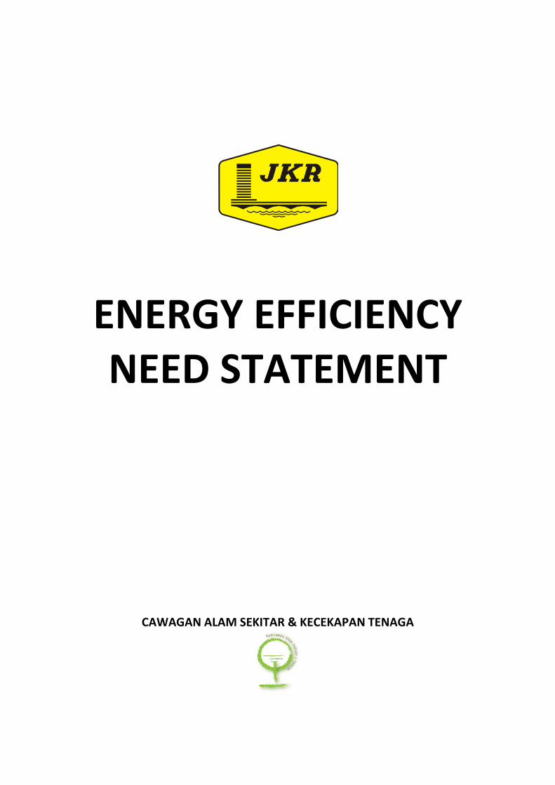
CONTENT
CKE
Abbreviation iii
1.0 General Condition 1
2.0 Architectural 3
2.1 Objective
2.2 Requirements
2.3 Submittals
2.4 Reference
3.0 Mechanical 5
3.1 Air-conditioning And Mechanical Ventilation (ACMV) Design
3.2 High Efficiency Motors/Booster Pump
3.3 Lift System
4.0 Electrical 11
4.1 Zoning Of Lighting System
4.2 Lighting Control System
4.3 Lighting System
4.4 Fan
4.5 Power Factor And Harmonic Distortion
4.6 Electrical Power Distribution System
4.7 Low Losses Transformer
5.0 Sub Metering 15
6.0 Energy Management Control System In Building Operation 16
7.0
Data Centre, Telecommunications & IT System
19
CKE
ENERGY EFFICIENCY
NEED STATEMENT
Issue : 01
Date Issued : 1 October 2014
PAGE II OF III
CKE
CONTENT
CKE
8.0 Building Energy Intensity 20
9.0 Training and Awareness 21
10.0 Project Documentation For Operations, Maintenance, Capacity
Building, Knowledge And Technology Transfer
22
11.0 Best Energy Management Practices 23
12.0 Commissioning & Tune-up 24
12.1 Objective
12.2 Commissioning Tasks
13.0 Payback Period 27
Contractor Checklist
CKE
ENERGY EFFICIENCY
NEED STATEMENT
Issue : 01
Date Issued : 1 October 2014
PAGE III OF III
CKE
ABBREVIATION
CKE
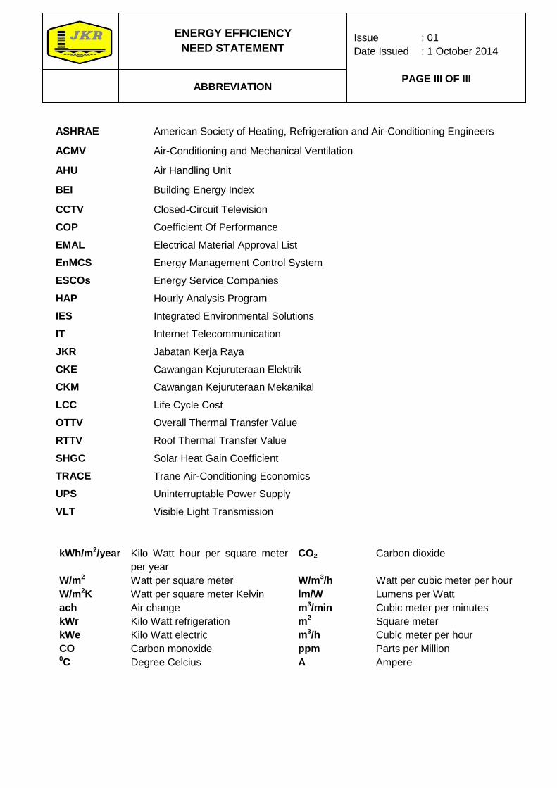
kWh/m2/year Kilo Watt hour per square meter
per year
CO2 Carbon dioxide
W/m2 Watt per square meter W/m3/h Watt per cubic meter per hour
W/m2K Watt per square meter Kelvin lm/W Lumens per Watt
ach Air change m3/min Cubic meter per minutes
kWr Kilo Watt refrigeration m2 Square meter
kWe Kilo Watt electric m3/h Cubic meter per hour
CO Carbon monoxide ppm Parts per Million 0C Degree Celcius A Ampere
ASHRAE American Society of Heating, Refrigeration and Air-Conditioning Engineers
ACMV Air-Conditioning and Mechanical Ventilation
AHU Air Handling Unit
BEI Building Energy Index
CCTV Closed-Circuit Television
COP Coefficient Of Performance
EMAL Electrical Material Approval List
EnMCS Energy Management Control System
ESCOs Energy Service Companies
HAP Hourly Analysis Program
IES Integrated Environmental Solutions
IT Internet Telecommunication
JKR
CKE
CKM
Jabatan Kerja Raya
Cawangan Kejuruteraan Elektrik
Cawangan Kejuruteraan Mekanikal
LCC Life Cycle Cost
OTTV Overall Thermal Transfer Value
RTTV Roof Thermal Transfer Value
SHGC Solar Heat Gain Coefficient
TRACE Trane Air-Conditioning Economics
UPS Uninterruptable Power Supply
VLT Visible Light Transmission
ENERGY EFFICIENCY
NEED STATEMENT
CKE
Issue : 01
Date Issued : 1 October 2014
PAGE 1 OF 27
SECTION 1.0
CKE
GENERAL CONDITIONS
CKE
1.1 The building shall be design to be a sustainable and green to the extent possible brief
current availability of building materials and M & E components and systems.
1.2 Building Energy Intensity (BEI) shall be proven in the design phase using advance
computer modeling tools, the IES software, ECOTECT or similar, as concurred by
JKR’S approval.
1.3 The overall efficiency of lighting and maintained illuminance levels for general building
areas shall comply with the latest version of MS 1525.
1.4 The building shall be designed according to the relevant standards, guidelines, policies
and directives pertaining to energy efficiency and green technology as follows:
a) Uniform Building By-Laws
b) MS 1525:2007 “Standard for Energy Efficiency and Use of Renewable Energy
in Non-Domestic Buildings” shall be used as a guide with assumption that
energy efficiency performance will achieve Building Energy Intensity (BEI)
≤150 kWh/m2/year as indicated in (c).
c) Garis Panduan dan Peraturan Bagi Perancangan Bangunan oleh
Jawatankuasa Standard dan Kos, Unit Perancang Ekonomi, Jabatan Perdana
Menteri, edisi tahun 2008, Bab 4.
d) Energy Efficiency and Conservation Guidelines for Malaysian Industries,
Part 1: Electrical Energy – use Equipment, July 2007 and Part 2 : Thermal
Energy-use Equipment, June 2010, Kementerian Tenaga, Teknologi Hijau
dan Air (KETTHA)
e) National Green Technology Policy, Kementerian Tenaga, Teknologi Hijau dan
Air (KETTHA), 2009
f) Handbook On Passive Design Strategies For Energy Efficient Building,
Cawangan Arkitek, 2010 (JKR20802-0012-09)
g) Design Strategies for Energy Efficiency in New Buildings (Non-Domestic),
Kementerian Tenaga Komunikasi dan Multimedia (KTKM), JKR and Danida,
2004
h) Energy Efficiency Guidelines For CKE Design

ENERGY EFFICIENCY
NEED STATEMENT
CKE
Issue : 01
Date Issued : 1 October 2014
PAGE 2 OF 27
SECTION 1.0
CKE
GENERAL CONDITIONS
CKE
1.5 Energy Efficiency is to be achieved, however, without compromising users comfort.
1.6 The cost of incorporating energy efficiency into the design is deemed to be included
and no separate cost shall be entertained.
1.7 In addition to this, the following design criteria shall be fulfilled in order to increase
energy efficiency of the building.
1.8 In the event of differences between the General Need Statement and Energy Efficiency
Need Statement versions of this statement, it is noted and agreed that the higher
requirements from either General Need Statement or Energy Efficiency Need
Statement shall prevail.
1.9 The contractor shall submit all the necessary documents as below;
a) Architectural conceptual design drawing (A3).
b) Air conditioning zoning drawing (A3).
c) Lighting Zoning drawing (A3).
d) Daylight zoning drawing (A3).
e) Energy simulation file (softcopy).
ENERGY EFFICIENCY
NEED STATEMENT
CKE
Issue : 01
Date Issued : 1 October 2014
PAGE 3 OF 27
SECTION 2.0
CKE
ARCHITECTURAL
CKE
2.1 Objective
The objective of this Architectural Energy Efficiency Need Statement is to encourage
architects to apply passive design strategies through creativity, innovation and varying
envelope components. This effort in the long run will give high impact reduction and low
operational cost in building’s energy consumption. By controlling and cutting down on heat
transfer shall reduce air-conditioning loads. Similarly, if daylight is optimized, then it can be
an important energy saving feature by displacing electric lighting demands.
2.2 Requirements
The overall building design shall incorporate and comply with the latest version of MS 1525:
Code of Practice on Energy Efficiency and Use of Renewable Energy for Non-Residential
Buildings. The Tenderers shall submit an Energy Efficient Design Report on items pertaining
to Section 4 (Architectural and Passive Design Strategies) and Section 5 (Building
Envelope).
a) Site planning and orientation;
For the analysis of the local microclimate condition (air temperature, radiant
temperature, relative humidity, air velocity and precipitation) reliable climate
data (of at least 20 years) for the site shall be used. The building’s main
longitudinal orientation shall be on an axis of 5º Northeast.
b) Daylighting;
Daylight penetration must be optimised but glare and heat shall be minimised
(refer Table 1a. and Table 13 in MS 1525). Daylight Factor Diagram® or Df-
TOOL® shall be used as daylight prediction tool.
c) Facade design;
The glass windows/fenestration system shall be protected from direct sunlight
during the day’s most solar heat gain and hottest months of the year.
d) Natural ventilation;
The orientation of the building shall be facing the most prevailing wind. Lobby
areas, corridors, lift cores, toilets and staircases shall be naturally ventilated.
Alternatively, if performance based approach is used, then compliance pertaining to Section
10 (Building Energy Simulation) from the latest version of MS 1525 must be met.
Additionally these targeted figures shall be established;
e) The design building annual energy use must demonstrated at least 6%
improved energy savings from the baseline building annual energy use using
the same simulation program.
ENERGY EFFICIENCY
NEED STATEMENT
CKE
Issue : 01
Date Issued : 1 October 2014
PAGE 4 OF 27
SECTION 2.0
CKE
ARCHITECTURAL
CKE
f) To achieve thermal performance compliance, out of 8,760 hours time step per
year, 60% of the simulated indoor temperature (without active means) of the
occupied space shall be between comfortable indoor temperature range in
Malaysia (24.5 – 28º Celsius).
2.3 Submittals
The following information for energy report shall be provided by a Professional Architect or
Professional Engineer, which includes but not limited to the following:
a) Submit a drawing showing building configuration, site planning and orientation
b) Submit a drawing showing daylight penetration 3 metres from external wall
and image capture of Daylight Factor Diagram® or Df-TOOL® results. The
windows used for the calculation must be coloured red in the drawing.
c) Submit a drawing showing sun path analysis where the shadows cast on the
glass windows/fenestration system from 9:30 am until 5:00 pm during the
months of March to July.
d) Submit a wind rose of the site and a drawing showing the building to be facing
the most prevailing wind.
e) Submit a drawing showing the naturally ventilated spaces in red.
f) Submit a drawing showing strategic landscaping; trees to help reduce heat
gain
g) Submit calculations of the OTTV calculation; (≤ 45W/m2) and
h) The RTTV calculation (≤ 20W/m2) of the roof assembly, if provided with
skylights. The BEIT software shall be used.
i) Calculations of U-values for roof and walls.
j) Submit a drawing showing the cross sections of typical parts of the roof
construction, giving details of the type and thickness of basic construction
materials, insulation and air space.
k) Submit a proposed glazing specifications on Shading Coefficient, U-values
and Visible Light Transmission
2.4 Reference
a) MS 1525:2014:Code of Practice on Energy Efficiency and Use of Renewable
Energy for Non-Residential Buildings
b) ASHRAE Standard 90.1 – 2004
c) Building Energy Efficiency Technical Guideline for Passive Design 2013,
BSEEP
d) Handbook on Passive Design Strategies for Energy Efficiency Buildings,
Cawangan Arkitek
e) Manual Penarafan Hijau pH JKR
ENERGY EFFICIENCY
NEED STATEMENT
CKE
Issue : 01
Date Issued : 1 October 2014
PAGE 5 OF 27
SECTION 3.0
CKE
MECHANICAL
CKE
3.1 Air-Conditioning and Mechanical Ventilation (ACMV) Design
3.1.1 Load calculations
3.1.1.1 Cooling system design loads for the purpose of sizing systems and equipment shall
be determined in accordance with the procedures described in the latest edition of
the ASHRAE handbook, or other equivalent publications.
3.1.1.2 Computerized load calculations shall be conducted on hourly basis using tools such
as Hourly Analysis Program (HAP), TRACE 700, E-20 or equivalent.
3.1.1.3 Design conditions (outdoor and indoor) of air conditioned space for comfort cooling
shall be as recommended by the latest version of MS 1525.
3.1.1.4 Alternative ACMV system (air system and refrigeration plant) comparison and its
corresponding energy demand shall be conducted. If not specified elsewhere in this
document, ACMV system with the least energy consumption shall be selected.
3.1.1.5 A comprehensive design report shall be submitted comprises all design input data,
design output and energy simulation result. The design report shall be endorsed by
professional engineer.
3.1.2 System/ Equipment Sizing and efficiency
3.1.2.1 Air conditioning systems and equipment shall comply to the latest version of MS
1525.
3.1.2.2 Where chillers are used and when the design load is greater than 1000kWr, a
minimum of two chillers should be provided to meet the required load. Should
consider standby chillers as well.
3.1.2.3 Minimum chiller efficiency (COP) shall be as set by the MS 1525 in order to have an
energy efficient system.
3.1.2.4 Individual air-cooled or water cooled direct expansion (DX) units greater than 35 kWr
(reciprocating compressor) or 65kWr (scroll compressor) should consist of either multi
compressors or single compressor with minimum step/variable unloaders. Refrigerant
type used should have Ozone Depletion Potential of zero (ODP=0).
ENERGY EFFICIENCY
NEED STATEMENT
CKE
Issue : 01
Date Issued : 1 October 2014
PAGE 6 OF 27
SECTION 3.0
CKE
MECHANICAL
CKE
3.1.2.5 Maximum allowable flow rate in pipes shall follow Ashrae 90.1 – 2007.
3.1.2.6 A presentation of pipe routing shall be made during the concept design stage to
show that the most efficient route has been selected for the chill water pipe system.
3.1.2.7 Detailed pump head computation shall be provided together with all supporting
documentation of pressure losses; i.e.
a. Friction losses in pipes
b. No. of bends
c. Valves and fittings k-value
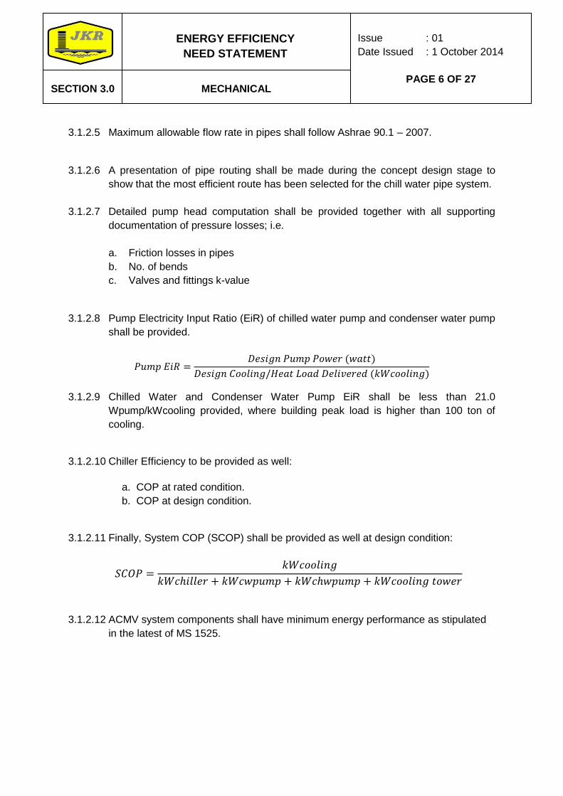
3.1.2.8 Pump Electricity Input Ratio (EiR) of chilled water pump and condenser water pump
shall be provided.
3.1.2.9 Chilled Water and Condenser Water Pump EiR shall be less than 21.0
Wpump/kWcooling provided, where building peak load is higher than 100 ton of
cooling.
3.1.2.10 Chiller Efficiency to be provided as well:
a. COP at rated condition.
b. COP at design condition.
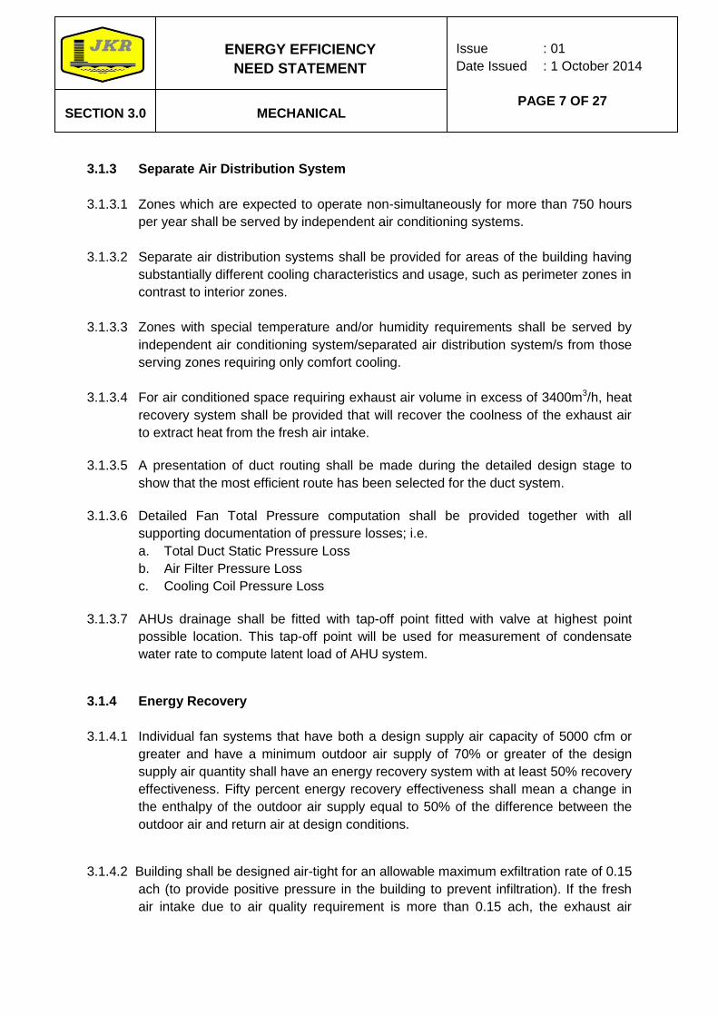
3.1.2.11 Finally, System COP (SCOP) shall be provided as well at design condition:
3.1.2.12 ACMV system components shall have minimum energy performance as stipulated
in the latest of MS 1525.
ENERGY EFFICIENCY
NEED STATEMENT
CKE
Issue : 01
Date Issued : 1 October 2014
PAGE 7 OF 27
SECTION 3.0
CKE
MECHANICAL
CKE
3.1.3 Separate Air Distribution System
3.1.3.1 Zones which are expected to operate non-simultaneously for more than 750 hours
per year shall be served by independent air conditioning systems.
3.1.3.2 Separate air distribution systems shall be provided for areas of the building having
substantially different cooling characteristics and usage, such as perimeter zones in
contrast to interior zones.
3.1.3.3 Zones with special temperature and/or humidity requirements shall be served by
independent air conditioning system/separated air distribution system/s from those
serving zones requiring only comfort cooling.
3.1.3.4 For air conditioned space requiring exhaust air volume in excess of 3400m3/h, heat
recovery system shall be provided that will recover the coolness of the exhaust air
to extract heat from the fresh air intake.
3.1.3.5 A presentation of duct routing shall be made during the detailed design stage to
show that the most efficient route has been selected for the duct system.
3.1.3.6 Detailed Fan Total Pressure computation shall be provided together with all
supporting documentation of pressure losses; i.e.
a. Total Duct Static Pressure Loss
b. Air Filter Pressure Loss
c. Cooling Coil Pressure Loss
3.1.3.7 AHUs drainage shall be fitted with tap-off point fitted with valve at highest point
possible location. This tap-off point will be used for measurement of condensate
water rate to compute latent load of AHU system.
3.1.4 Energy Recovery
3.1.4.1 Individual fan systems that have both a design supply air capacity of 5000 cfm or
greater and have a minimum outdoor air supply of 70% or greater of the design
supply air quantity shall have an energy recovery system with at least 50% recovery
effectiveness. Fifty percent energy recovery effectiveness shall mean a change in
the enthalpy of the outdoor air supply equal to 50% of the difference between the
outdoor air and return air at design conditions.
3.1.4.2 Building shall be designed air-tight for an allowable maximum exfiltration rate of 0.15
ach (to provide positive pressure in the building to prevent infiltration). If the fresh
air intake due to air quality requirement is more than 0.15 ach, the exhaust air
ENERGY EFFICIENCY
NEED STATEMENT
CKE
Issue : 01
Date Issued : 1 October 2014
PAGE 8 OF 27
SECTION 3.0
CKE
MECHANICAL
CKE
system shall be designed to exhaust the additional air from the building and channel
it to the heat recovery where the following conditions are met:
a. The total exhaust air volume is more than 70% of the fresh air intake volume.
b. Areas where total exhaust and 100% fresh air is required, such as Operating
Theatre, Autopsy Rooms, etc.
3.1.5 Control
3.1.5.1 Temperature control.
Each system should be provided with at least one thermostat for the regulation of
temperature. Each thermostat should be capable of being set by adjustment or
selection of sensors over a minimum range of between 22°C to 27°C.
3.1.5.2 Humidity control.
3.1.5.2.1 In a system requiring moisture removal to maintain specific selected
relative humidity in spaces or zones, no new energy (such as electric
reheat) shall be used to produce a space relative humidity as stated in
the latest version of MS 1525.
3.1.5.2.2 Air conditioning system for spaces primarily designed for non comfort
cooling purposes, which require precise control of humidity (such as
Operation Theatre, Library, Drug Store), reheat system utilizing
recovered energy such as from condenser water, de-superheater, heat
recovery wheel, heat pipe and other energy recovery technology shall
be used. Use of electric reheat can only be considered if the use of
above technologies is not technically feasible due to site or building
conditions.
3.1.5.3 Zoning for Temperature Control.
At least one thermostat for regulation of space temperature shall be provided for
each separate system and each separate zone. As a minimum, each floor of a
building should be considered as a separate zone. On a multi-storey building
where the perimeter system offsets only the transmission gains of the exterior wall,
an entire side of uniform exposure may be zoned separately.
ENERGY EFFICIENCY
NEED STATEMENT
CKE
Issue : 01
Date Issued : 1 October 2014
PAGE 9 OF 27
SECTION 3.0
CKE
MECHANICAL
CKE
3.1.5.4 Control Setback and Shutoff.
Each system shall be equipped with a readily accessible means of shutting off or
reducing the energy used during periods of non-use or alternate uses of the building
spaces or zones served by the system The following are examples that meet these
requirements:-
a) Manually adjustable automatic timing devices
b) Manual devices for use by operating personnel
c) Automatic control system
d) Occupancy Sensors
3.1.5.5 Off hour control.
ACMV system shall be equipped with automatic controls i.e weekly timers,
scheduler for use during periods of non-use or alternative use of the spaces served
by the system. Equipment with connected load less than 2kWe each may be
controlled by readily accessible manual switch.
3.1.5.6 Outdoor and Exhaust air control.
Outdoor air supply and exhaust systems with design capacity more than 1800 m3/h
shall be provided with motorized dampers interlocked with equipments operation.
Outdoor air supply motorized damper shall be modulated based on level of CO2
measured in the return air stream. Maximum allowable CO2 level in the manned
spaces is 1000 ppm. Use of gravity damper is not allowed.
3.1.5.7 Mechanical Ventilation Control.
Each mechanical ventilation system (supply and/or exhaust) shall be equipped with
a readily accessible switch or other means for shut-off or volume reduction when
ventilation is not required. Examples of such devices would include timer switch
control, thermostat control, duty cycle programming and CO/CO2 sensor control.
ENERGY EFFICIENCY
NEED STATEMENT
CKE
Issue : 01
Date Issued : 1 October 2014
PAGE 10 OF 27
SECTION 3.0
CKE
MECHANICAL
CKE
3.1.6 Fan System Efficacy
3.1.6.1 Fan system with air flow rate exceeds 17,000 m3/h and operating for more than
750 hours per year shall have overall fan efficacy of not more than 0.35 W/m3 of
air flow rate.
3.1.6.2 Minimum Fan Efficiency shall be in accordance to ‘Energy Efficiency and
Conservation Guideline for Industrial Electrical Equipments – Part 1, published by
Pusat Tenaga Malaysia.
3.2 High Efficiency Motors/Booster Pumps
All motors used for any mechanical system should be energy efficiency motor
according to the latest version of MS 1525.
3.3 Lift System
3.3.1 The lift shall be of energy efficient type, driven by variable velocity variable
frequency (VVVF) motors.
3.3.2 The lift motor rooms shall be designed with minimum requirement of cooling (if
any) and ventilation system.
3.3.3 All motor used for lift drive shall be of high efficiency motor complied with MS
1525.
3.3.4 Regenerative drives which are systems that can convert or store braking energy
from a moving lift car.
3.3.5 Switch off car lighting and ventilation fan when idling more than 2 minutes.
3.3.6 Energy efficient lighting such as LED lighting, compact fluorescent, etc.
3.4 Need Statement and other technical documents of Cawangan Kejuruteraan
Mekanikal of JKR for Mechanical Services take precedence should there be
any contradiction.
ENERGY EFFICIENCY
NEED STATEMENT
CKE
Issue : 01
Date Issued : 1 October 2014
PAGE 11 OF 27
SECTION 4.0
CKE
ELECTRICAL
CKE
4.0 The energy saving criteria shall be incorporated in all design, installations and
equipment.
4.1 Zoning of lighting system
4.1.1 The lighting system in the building shall be designed with multiple zones according
to:
a) Daylight availability especially for rooms or area near the façade.
b) Controls of artificial lighting system.
c) Reasonable number of beds per lighting zones (for hospital / clinic)
4.1.2 The purpose of having multi zones of lighting system is to provide flexibility to
control the operation of the artificial lighting system thus to eliminate energy
wastage in the system.
4.1.3 The zoning might also be associated with automatic lighting control system such as
sensors, controllers and building control system.
4.1.4 Office rooms near the façade shall have a minimum of two separate lighting circuits.
The lighting circuits shall be designed parallel to the façade or perimeter of the
building.
4.2 Lighting control system
4.2.1 The electrical lighting control panel shall have contactors for interfacing and control
by the building control system / energy management system. All lighting control
schedules and zoning shall reside in the system.
4.2.2 In those areas, outside or inside, where daylight is available, lighting shall be
controlled by a daylight photocell and occupancy sensors. The control of the lighting
circuit with photocell shall be designed according to the daylight availability. All
lighting circuits shall have a motion sensor that would cut off lights if motion is not
detected during a preset time period (1 – 10 minutes).
4.2.3 The switching of lights at temporary habitable areas such as corridors, waiting
areas, toilets, surau, staircases and open public area, shall have the most practical
lighting control strategy to eliminate energy wastage, but at the same time shall
comply with safety requirement such as CCTV.
4.2.4 The lighting control shall be fully user programmable and allows time-of-day, day-of-
week, and holiday scheduling of all lights. It shall also allow for user’s temporary
ENERGY EFFICIENCY
NEED STATEMENT
CKE
Issue : 01
Date Issued : 1 October 2014
PAGE 12 OF 27
SECTION 4.0
CKE
ELECTRICAL
CKE
after-hours lighting needs through the use of Telephone Dial-in Operator or
computer interface system commands.
4.3 Lighting System
4.3.1 The lighting system shall use energy efficient lighting such as:
a) Energy efficient tubes for general office area (T5, LEDs, CCFL or better).
However other type of lighting tubes are allowable to be installed at other area
(example: store, utility area, service room, etc)
b) Use of low loss magnetic ballast or electronic ballast.
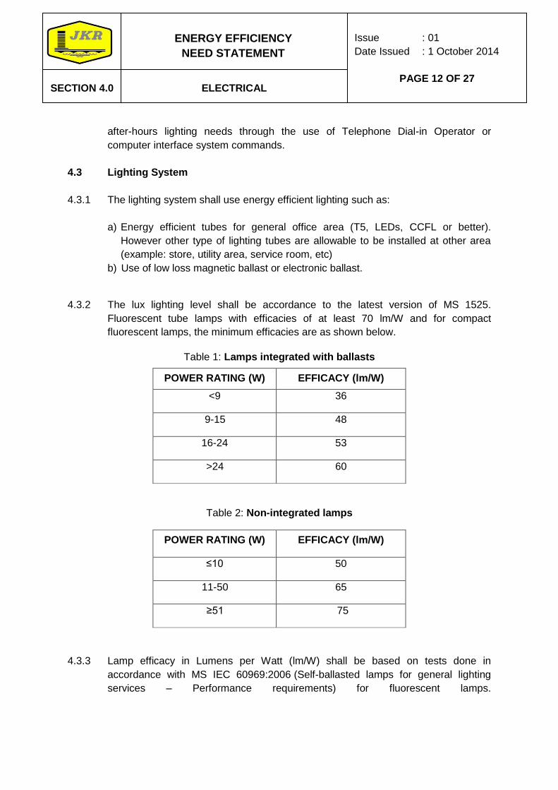
4.3.2 The lux lighting level shall be accordance to the latest version of MS 1525.
Fluorescent tube lamps with efficacies of at least 70 lm/W and for compact
fluorescent lamps, the minimum efficacies are as shown below.
Table 1: Lamps integrated with ballasts
POWER RATING (W) EFFICACY (lm/W)
<9 36
9-15 48
16-24 53
>24 60
Table 2: Non-integrated lamps
POWER RATING (W) EFFICACY (lm/W)
≤10 50
11-50 65
≥51 75
4.3.3 Lamp efficacy in Lumens per Watt (lm/W) shall be based on tests done in
accordance with MS IEC 60969:2006 (Self-ballasted lamps for general lighting
services – Performance requirements) for fluorescent lamps.
ENERGY EFFICIENCY
NEED STATEMENT
CKE
Issue : 01
Date Issued : 1 October 2014
PAGE 13 OF 27
SECTION 4.0
CKE
ELECTRICAL
CKE
4.3.4 LED lamp with efficacy of at least 55 lm/W for integrated lamps excluding the
transformer. LED efficacy shall be based on the latest test accordance to the
accepted standard if any.
4.3.5 The luminaires shall be of type approved by JKR Electrical Material Approval List
(EMAL). The luminaires shall comply with IEC 60598, IES LM-79-08, IEC 62471,
IEC 61547, IEC 61000-3-2, and BS EN 55015.
4.3.6 The common corridor, public areas etc. shall have two levels of illuminance
(evening/night) such that after midnight, the lighting can be reduced to a lower level.
4.3.7 The switching of these lights shall be by automatic time switches complete with 24
hours spring reserve and manual override or by other appropriate methods.
4.3.8 Dual timer switches for compound lighting to allow reduced illumination levels.
4.4 Fan
4.4.1 All ceiling fans shall be energy saving. All fans should have Coefficient of
Performance (COP) value of at least 2.66 for ceiling fans. COP based on tests done
in accordance with MS1220:2001.
4.4.2 Ceiling fans offered shall be complying with MS 1219, MS 1220 and JKR EMAL.
For 1500mm sweep ceiling fan, the power consumption at full speed shall not be
more than 80 watts at rated voltage, and the minimum air delivery shall not be less
than 210m3/min. Safety thermal fuse (130 0 C, 2A) shall be incorporated against
power surge and overheat.
4.5 Power Factor & Harmonic Distortion
4.5.1 An adequate automatic capacitor compensate system shall be installed to regulate
the power factor of the electrical power supply. The power factors shall not be less
than 0.85 for low voltage system and high voltage system.
4.5.2 To maintain good power quality in the electrical network distribution, the maximum
Voltage of Total Harmonic Distortion (THD) shall not be more than 5%.
4.6 Electrical power distribution system.
4.6.1 The design of electrical power distribution system shall be reflected according to
energy monitoring requirement.
ENERGY EFFICIENCY
NEED STATEMENT
CKE
Issue : 01
Date Issued : 1 October 2014
PAGE 14 OF 27
SECTION 4.0
CKE
ELECTRICAL
CKE
4.7 Low Losses Transformer
4.7.1 The substation for the main electrical supply intake shall have low losses
transformer system. The transformer shall be able to reduce the losses
automatically according to the power supply demand in the buildings. The
transformer shall be of low iron loss and low copper loss cast resin type dry type
complying with the relevant Malaysian Standard or IEC recommendations. The no-
load loss and total losses shall not exceed the values specified. The tolerance shall
be in accordance with MS IEC 60076-1.
ENERGY EFFICIENCY
NEED STATEMENT
CKE
Issue : 01
Date Issued : 1 October 2014
PAGE 15 OF 27
SECTION 5.0
CKE
SUB METERING
CKE
5.1 Digital Electrical Energy Meters shall be installed at sub-switch board serving, but
not limited to the following:
a) Central air-conditioning b) Lift and escalator system c) Major water pump system d) General power supply e) Lighting supply f) Data Centre/Server Room
ENERGY EFFICIENCY
NEED STATEMENT
CKE
Issue : 01
Date Issued : 1 October 2014
PAGE 16 OF 27
SECTION 6.0
CKE
ENERGY MANAGEMENT CONTROL
SYSTEM IN BUILDING OPERATION
CKE
6.1 The Contractor shall propose a comprehensive energy management component within
the building automation system. Continuous monitoring of the energy performance and
the comfort perimeter use is vital achieving energy savings in building.
6.2 The Building Management System shall include a comprehensive Energy
Management Control System (EnMCS), comprising of both software and hardware,
which shall be able to provide monitoring (including graphics interface), control and
reporting of the whole building energy status.
6.3 According to the MS 1525:2007 – Section 9.1:Energy Management System (EMS), the
EnMCS shall be considered for buildings having area greater than 4000m² of air-
conditioned space where it is a subset of the building automation system function.
6.4 Comprehensive Energy Management Control System shall be implemented as part of
the Building Control and Automation System. The energy management system shall
monitor all energy flows in the building, floor by floor. The minimum energy
management features shall be as listed below:
a) Monitoring and trending of electricity consumption for plug loads per floor
b) Monitoring and trending of electricity consumption for general office lighting per
floor.
c) Monitoring and trending of fan energy consumption per AHU.
d) Monitoring and trending of electricity consumption for chilled water pump and
condenser water pump.
e) Monitoring and trending of the chiller Coefficient of Performance with breakdown
of cooling power delivered and electricity consumed.
f) Monitoring and trending of AHU on-coil and off-coil temperature and static
pressure.
g) Monitoring and trending of CO2 from the return air.
h) Monitoring and trending of supply and return chill water temperature of each
AHU.
i) Monitoring and trending of Room temperatures per VAV zones.
j) Monitoring and trending Air temperature and humidity level for every zone; the
supply from 1 AHU is considered as 1 zone.
k) Monitoring and trending of Electricity consumption of lifts (and escalators if
used).
l) Monitoring and trending of Miscellaneous electricity consumption, including
toilets
m) Displaying the energy trending on screen and printout.
ENERGY EFFICIENCY
NEED STATEMENT
CKE
Issue : 01
Date Issued : 1 October 2014
PAGE 17 OF 27
SECTION 6.0
CKE
ENERGY MANAGEMENT CONTROL
SYSTEM IN BUILDING OPERATION
CKE
6.5 The EnMCS system shall provide hourly load profile, daily, weekly and monthly energy
consumption in kWh/m2 per floor, and projected annual energy consumption in kWh/m2
based on current day energy consumption of the building.
6.6 All energy flows, temperatures and radiation data shall be stored in the computer, and
reports of the performance on a daily, weekly and monthly basis shall be computed
automatically. Also, trending of all parameters shall be provided automatically.
6.7 A comprehensive 2 years monitoring program shall be implemented covering the
energy consumption for:
a) Refrigeration plant
b) Lighting
c) Computers
d) Other plug loads
e) Electricity consumption for AHU
f) Miscellaneous electricity consumption including toilets
6.8 The building management system shall be reliable, easy to operate and maintain. The
system shall be open protocol type such as using TCP-IP, Lon Works, ModBus (or
equivalent) communication system, integrated with web-based interface feature and
shall be operated remotely through intranet and internet using common web internet
software such as Microsoft Internet Explorer, Firefox, Netscape, Opera, etc.
6.9 The building management system shall have maximum demand control incorporated
into the system for ensure that building does not incur high maximum demand cost.
6.10 Furthermore, the following indoor climate and comfort parameters shall be assessed
and evaluated:
a) Air temperature, mean radiant temperature, relative humidity, CO2 levels and air
velocity for the various areas of the building.
b) Illumination and glare for the various areas of the building.
6.11 The various controls energy for M&E systems shall be evaluated and compared to the
design/ideal controls strategies:
a) Control of electrical lighting, according to the occupancy and daylight availability.
b) Control of the ventilation and the cooling system according to variations in inner
loads, exterior loads and occupancy.
c) Control of cooling input and stability of temperatures
d) Any other control strategies (depending on the final design chosen)
ENERGY EFFICIENCY
NEED STATEMENT
CKE
Issue : 01
Date Issued : 1 October 2014
PAGE 18 OF 27
SECTION 6.0
CKE
ENERGY MANAGEMENT CONTROL
SYSTEM IN BUILDING OPERATION
CKE
6.12 Measured performance data shall be normalized to the standard design condition so
that the actual performance can be compared with the predicted performance. On the
monthly basis, analysis of the monitoring data shall be done so that it is possible to
verify how much off target the energy consumption and the indoor comfort conditions
are. Also, proposal for improved performance shall be given on a monthly basis and
after the next month, follow up of the measures shall be made to see whether the
goals have been achieved.
6.13 For each month, and energy performance report shall be presented to the
management of the building owner. This report shall include but not restricted to the
following areas.
a) Energy index of the month, actual and normalized.
b) Assessment of energy consumption for each category.(lights, computers etc.)
c) Assessment of the indoor comfort parameters (temperature, humidity, light, etc.)
d) Proposal for measures to improve energy efficiency
e) Follow up on previous initiative for improving energy efficiency.
f) Overall assessment of energy performance and indoor comfort of the building
6.14 The Contractor shall follow all guidelines by the relevant agencies and refer to the
latest version of MS 1525. The Contractor shall propose and demonstrate clearly the
overall concept of EE with the appointed consultant for JKR’s approval.

ENERGY EFFICIENCY
NEED STATEMENT
CKE
Issue : 01
Date Issued : 1 October 2014
PAGE 19 OF 27
SECTION 7.0
CKE
DATA CENTRE, YELECOMMUNICATIONS
& IT SYSTEM
CKE
7.1 The data centre, telecommunications and IT system shall be designed with
preference to energy efficiency approach.
7.2 Supporting IT equipment generating heat such as UPS and transformers shall be
isolated from the IT equipment rooms.
7.3 The cooling and ventilation of these systems shall be designed to minimum
requirements of the specification and comply with the latest version of ASHRAE
Environmental Guidelines for Datacom Equipment.
ENERGY EFFICIENCY
NEED STATEMENT
CKE
Issue : 01
Date Issued : 1 October 2014
PAGE 20 OF 27
SECTION 8.0
CKE
BUILDING ENERGY INTENSITY
CKE
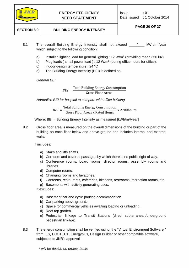
8.1 The overall Building Energy Intensity shall not exceed ________ kWh/m2/year
which subject to the following condition:
a) Installed lighting load for general lighting : 12 W/m2 (providing mean 350 lux)
b) Plug loads ( small power load ) : 12 W/m² (during office hours for office),
c) Indoor design temperature : 24 oC
d) The Building Energy Intensity (BEI) is defined as:
General BEI
Normalize BEI for hospital to compare with office building
Where; BEI = Building Energy Intensity as measured [kWh/m²/year]
8.2 Gross floor area is measured on the overall dimensions of the building or part of the
building on each floor below and above ground and includes internal and external
walls.
It includes:
a) Stairs and lifts shafts.
b) Corridors and covered passages by which there is no public right of way.
c) Conference rooms, board rooms, director rooms, assembly rooms and
libraries.
d) Computer rooms.
e) Changing rooms and lavatories.
f) Canteens, restaurants, cafeterias, kitchens, restrooms, recreation rooms, etc.
g) Basements with activity generating uses.
It excludes:
a) Basement car and cycle parking accommodation.
b) Car parking above ground.
c) Space for commercial vehicles awaiting loading or unloading.
d) Roof top garden.
e) Pedestrian linkage to Transit Stations (direct subterranean/underground
pedestrian linkage).
8.3 The energy consumption shall be verified using the “Virtual Environment Software “
from IES, ECOTECT, Energyplus, Design Builder or other compatible software,
subjected to JKR’s approval
*
* will be decide on project basis
ENERGY EFFICIENCY
NEED STATEMENT
CKE
Issue : 01
Date Issued : 1 October 2014
PAGE 21 OF 27
SECTION 9.0
CKE
TRAINING AND AWARENESS
CKE
9.1 The Contractor shall provide two levels of training and awareness on the use of the
building:
a) Level 1 is meant to provide awareness and concept of energy savings and
environmental management to users & building occupants, the building’s
O&M crew, and Facility Management.
b) Level 2 is meant to guide users & building occupants on the actual operations
and on the use of the facilities provided for in the building.
ENERGY EFFICIENCY
NEED STATEMENT
CKE
Issue : 01
Date Issued : 1 October 2014
PAGE 22 OF 27
SECTION
10.0
CKE
PROJECT DOCUMENTATION FOR
OPERATIONS, MAINTENANCE, CAPACITY
BUILDING, KNOWLEDGE AND
TECHNOLOGY TRANSFER
CKE
10.1 Complete operations & maintenance (O&M) document which shall include, but not
limited to, building specifications, proposed O&M schedules, trainings and list of
respective equipment suppliers, shall be provided.
10.2 The manual shall be written and diagramed for easy understanding by technician
level people that will be operating the building.
10.3 The project shall implement good project documentation in softcopy and hardcopy
which include the design, implementation, testing & commissioning and fine-tuning
(if any) of the building system. The documents shall contain, but not limited to the
following;
a) Design and feasibility studies reports.
b) Construction and As-Built drawings.
c) Detailed information of building materials.
d) Life cycle cost analysis of energy efficient system; this includes making
comparative analysis between costs in installing Energy Efficiency features
and costs without Energy Efficiency features.

ENERGY EFFICIENCY
NEED STATEMENT
CKE
Issue : 01
Date Issued : 1 October 2014
PAGE 23 OF 27
SECTION
11.0
CKE
BEST ENERGY MANAGEMENT
PRACTICES
CKE
11.1 The Facility Management (on behalf of building’s owner) shall be involved during
installation, testing and commissioning works of the active and passive Energy
Efficiency features.
ENERGY EFFICIENCY
NEED STATEMENT
CKE
Issue : 01
Date Issued : 1 October 2014
PAGE 24 OF 27
SECTION
12.0
CKE
COMMISSIONING & SET-UP
CKE
12.0.1 The building energy intensity of _____ kWh/m2/year shall be proven with 1 full year
of actual measurement made from the building within 2 years of handing over the
building to the client and the result should be certified by Energy Manager
registered with Suruhanjaya Tenaga. The contractor shall have maximum of 1 year
of fine-tuning period before the start of actual measurement is made. Adjustment
may be made to the actual building if there are any special operating conditions
such as unusually high occupancy density, unusually high small plug load or any
other circumstances beyond the control of the contractor. The adjusted calculation
methodology to be employed has to be mutually agreed upon.
12.0.2 If the 1 full year of actual measurement made of the building energy intensity
exceeds the requirement, it will be considered as a building defect that will need to
be rectified by the Contractor.
12.0.3 Prior to occupancy, after construction ends, with all interior finishes installed, the
Contractor shall perform a building flush out.
12.0.4 The Contractor shall conduct an air-sampling test after the flush out consistent with
an approved testing protocol.
12.0.5 A commissioning agent shall be appointed and be subjected to JKR approval. The
commissioning agent shall be knowledgeable about building mechanical and
electrical systems and be appointed from one of the following:
a) Building Services Consultant or,
b) M&E Contracting Engineer or,
c) Energy Consultant or,
d) Third party Energy Service Companies (ESCOs) or,
e) JKR’s qualified personnel.
12.0.6 The commissioning agent shall not be the same person as the design engineer for
the project.
12.1 Objective
12.1.1 Commissioning agent shall provide commissioning services to JKR. Commissioning
applies a systematic investigation process for improving and optimizing a building’s
operation and maintenance (O&M).
12.1.2 Commissioning ensures system functionality. It is an inclusive and systematic
process intended not only to optimize how equipment and systems operate, but
also to optimize how the systems function together. The commissioning process
must focuses on the dynamics of energy-using systems with the goal of reducing
energy wastages, obtaining energy cost savings for the owner, and identifying and
fixing existing and potential problems.
*
* will be decide on project basis
ENERGY EFFICIENCY
NEED STATEMENT
CKE
Issue : 01
Date Issued : 1 October 2014
PAGE 25 OF 27
SECTION
12.0
CKE
COMMISIONING & TUNE UP
CKE
12.1.3 The commissioning agent shall be fine-tuning the building for a minimum of 1 (one)
full year after the handing over of the building to the client.
12.2 Commissioning Tasks
12.2.1 The commissioning process consists of four primary phases:
12.2.1.1 Planning phase
a) Develop commissioning objectives.
b) Review available documentation.
c) Develop commissioning plan.
d) Deliverables: Commissioning plan, on the following areas:
(i) Chillers & pumps efficiencies
(ii) Cooling Tower efficiencies
(iii) AHU fan efficiencies
(iv) VAVs & VSDs
(v) Lighting control system.
(vi) Daylight control system (if available)
(vii) Daylight Factors measurement at Daylit spaces
(viii) Standby-power of building and all major equipments
(ix) Other Hydraulic systems
(x) Lift and escalators
(xi) Façade & outdoor lighting
(xii) Carpark ventilation & lighting efficiencies
(xiii) Infiltration measurement
(xiv) CO2 & motorized fresh air damper
12.2.1.2 Commissioning phase
a) Perform site assessment
b) Obtain or develop missing documentation
c) Develop and execute diagnostic monitoring and test plans
d) Develop and execute functional test plans
e) Analyze result
f) Develop Master List of deficiencies and improvements
g) Recommend improvements for implementation
h) Deliverables: Commissioning report with Master List of Deficiencies,
recommended improvements and energy saving calculations
ENERGY EFFICIENCY
NEED STATEMENT
CKE
Issue : 01
Date Issued : 1 October 2014
PAGE 26 OF 27
SECTION
12.0
CKE
COMMISIONING & TUNE UP
CKE
12.2.1.3 Tune-up phase
a) Implement repairs and improvements
b) Retest and re-monitor for results
c) Fine-tune improvements if needed
d) Revise estimated energy saving calculations
e) Deliverables: Tune-up report with improvement made, Master List of
Deficiencies (for unresolved items), recommended improvements and
energy saving calculations.
12.2.1.4 Project hand-off and integration phase
a) Prepare and submit final report
b) Perform deferred tests (if needed)
c) Develop building operation and maintenance plan/schedule/guidelines
d) Deliverables:
(i) Final report with Master List of Deficiencies (for unresolved items),
recommended improvements, energy saving calculations.
(ii) The original and corrected (if any was made) commissioning plan
(iii) Develop an O&M document that can be understood by the building
operators, facility managers or energy managers. Include full written
sequences of operation for the building and all equipments within it.
(iv) Develop guidelines for implementing a preventative maintenance
plan.
(v) Develop a comprehensive training plan for appropriate building staff
to attend training in general O&M concepts and for specific
equipment and systems. This will include both building operators
and facility managers or owners.
(vi) Conduct overall system level training of maintenance staff to
communicate the design intent, theory of system operation, delineate
the function of individual components in the system, and intersystem
functional operations
(vii) Develop guidelines and recommendations for maintaining an energy
accounting and tracking system.
(viii) Develop an operations assessment program and systems tune-up
and re-commissioning schedule.
ENERGY EFFICIENCY
NEED STATEMENT
CKE
Issue : 01
Date Issued : 1 October 2014
PAGE 27 OF 27
SECTION
13.0
CKE
PAYBACK PERIOD
CKE
13.1 All energy efficient system that has been proposed shall include financial analysis
calculation, of minimum of Simple Payback Period method.
13.2 Selection of the proposed system shall be based on financial analysis calculation
and subjected to JKR’s approval.

Contractor Checklist
Project Name:
No. Items Submitted (√/X)
1. To check inclusion of all necessary documents as listed below in tender submission:
a.
Compulsory drawings (A3): i. All floor plans
ii. Front elevation, Back elevation
iii. 2 side elevations
iv. Architectural conceptual design
v. Air conditioning zoning
vi. Lighting Zoning
vii. Daylight zoning drawing
All drawings shall be endorsed by professional engineer or architect, follow each discipline.
b. Documents related to Energy Efficiency features (i.e product catalog and etc)
c. Energy consumption simulation using Virtual Environment Software from IES, Energy plus, Designbuilder or compatible softwares.
TABLE A: ENERGY EFFICIENCY DATA
Building Information Please fill in the blanks
Total Floor Area in m2:
Air Conditioned Floor Area in m
2:
Gross Floor Area (follow GFA definition as stated in Need Statement)
Estimated Total Energy Consumption (kwh):
Estimated Weighted Operating Hours/Rated Hours (hrs/year):
Estimated Building Energy intensity (kwh/m²/year):
Architectural Energy Data
Estimated OTTV (W/m²)
Estimated RTTV (W/m²)
Targeted Infiltration rate:
Daylit spaces (%):
Mechanical Energy Data
Chiller plant system COP:
Peak cooling load provided for building (kWcooling):
COP of chiller:
Chill water pump power (kW):
Condenser water pump power (kW):
Cooling tower power (kW):
VRV chiller used (Yes/No):
VSD chill water pump used (Yes/No):
VSD condenser water pump used (Yes/No):
VSD cooling tower used (Yes/No):
VAV system used (Yes/No):
Average combined fan, motor and belt efficiency for AHU(%):
Fan total pressure (Pa):
Other mechanical system, total energy consumption (kw):System........................
Other mechanical system, total energy consumption (kw):System........................
Page 1 of 2
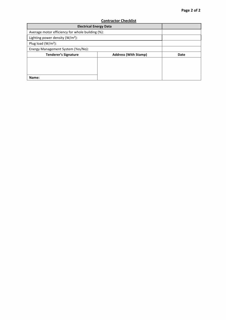
Contractor Checklist
Electrical Energy Data
Average motor efficiency for whole building (%):
Lighting power density (W/m²):
Plug load (W/m²):
Energy Management System (Yes/No):
Tenderer’s Signature Address (With Stamp) Date
Name:
Page 2 of 2