Embed Size (px)
Citation preview
1
Energy Control Centers
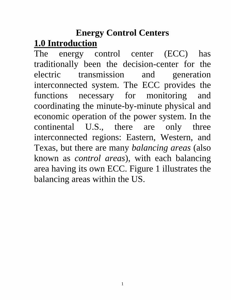
1.0 Introduction
The energy control center (ECC) has
traditionally been the decision-center for the
electric transmission and generation
interconnected system. The ECC provides the
functions necessary for monitoring and
coordinating the minute-by-minute physical and
economic operation of the power system. In the
continental U.S., there are only three
interconnected regions: Eastern, Western, and
Texas, but there are many balancing areas (also
known as control areas), with each balancing
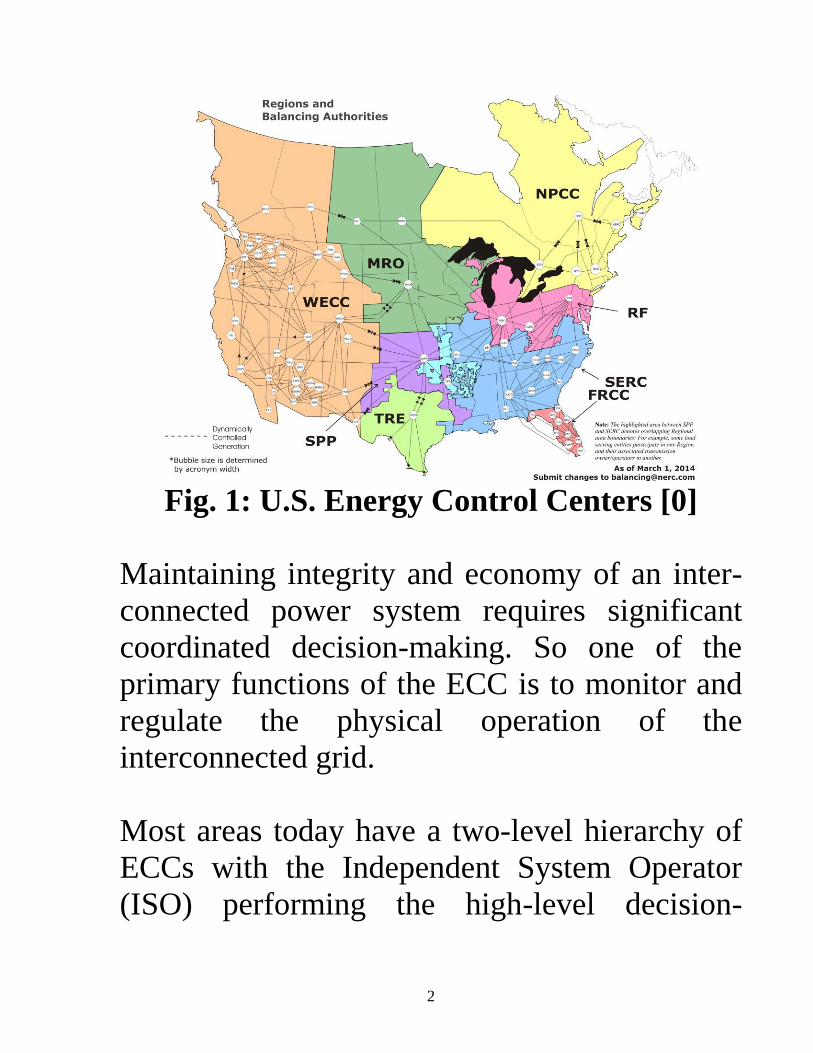
area having its own ECC. Figure 1 illustrates the
balancing areas within the US.
2
Fig. 1: U.S. Energy Control Centers [0]
Maintaining integrity and economy of an inter-
connected power system requires significant
coordinated decision-making. So one of the
primary functions of the ECC is to monitor and
regulate the physical operation of the
interconnected grid.
Most areas today have a two-level hierarchy of
ECCs with the Independent System Operator
(ISO) performing the high-level decision-
3
making and the transmission owner ECC
performing the lower-level decision-making.
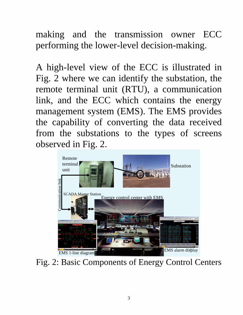
A high-level view of the ECC is illustrated in
Fig. 2 where we can identify the substation, the
remote terminal unit (RTU), a communication
link, and the ECC which contains the energy
management system (EMS). The EMS provides
the capability of converting the data received
from the substations to the types of screens
observed in Fig. 2.
27
Substation
Remote
terminal
unit
SCADA Master Station
Co
mm
unic
atio
n l
ink
Energy control center with EMS
EMS alarm displayEMS 1-line diagram
Fig. 2: Basic Components of Energy Control Centers

4
In these notes we will introduce the basic
components and functionalities of the ECC.
Note that there is no chapter in your text which
provides this information.
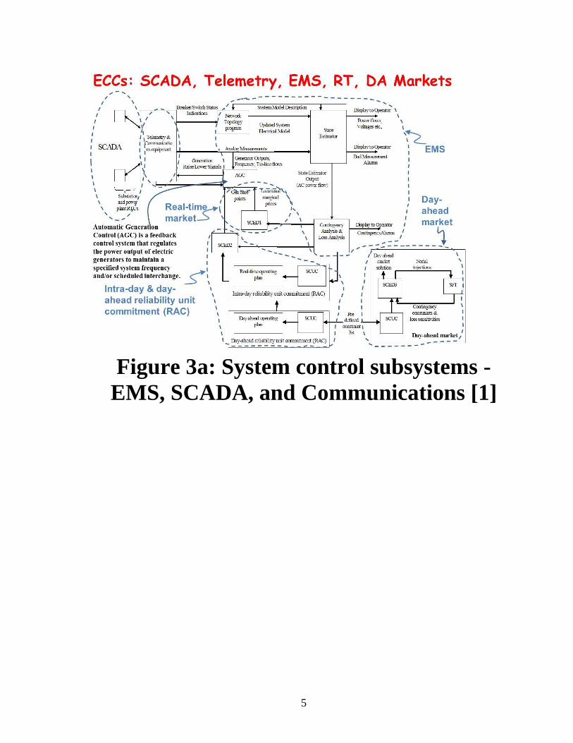
2.0 ECC Components The system control function traditionally used in
electric utility operation consists of three main
integrated subsystems: the energy management
system (EMS), the supervisory control and data
acquisition (SCADA), and the communications
interconnecting the EMS and the SCADA
(which is often thought of as part of the SCADA
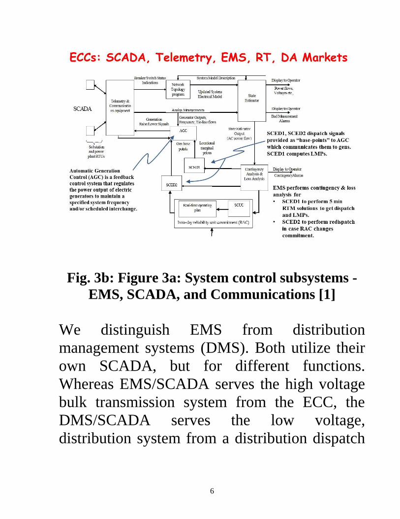
itself). Figure 3a [1] provides a block diagram
illustration of these three integrated subsystems
and Fig. 3b provides a closer view. The SCADA
and communications subsystems are indicated
in the dotted ovals at the top left hand corner of
the figure. The rest of the figure indicates the
EMS. We will describe each one in the
following subsections.
5
Figure 3a: System control subsystems -
EMS, SCADA, and Communications [1]
6
Fig. 3b: Figure 3a: System control subsystems -
EMS, SCADA, and Communications [1]
We distinguish EMS from distribution
management systems (DMS). Both utilize their
own SCADA, but for different functions.
Whereas EMS/SCADA serves the high voltage
bulk transmission system from the ECC, the
DMS/SCADA serves the low voltage,
distribution system from a distribution dispatch
7
center. We are addressing in these notes the
EMS/SCADA.
2.1 SCADA
There are two parts to the term SCADA [2-5].
Supervisory control indicates that the operator,
residing in the energy control center (ECC), has
the ability to control remote equipment. Data
acquisition indicates that information is
gathered characterizing the state of the remote
equipment and sent to the ECC for monitoring
purposes.
The monitoring equipment is normally located
in the substations and is consolidated in what is
known as the remote terminal unit (RTU).
Generally, the RTUs are equipped with
microprocessors having memory and logic
capability, together with some form of telemetry
to provide the communication link to the ECC.
8
Relays located within the RTU, on command
from the ECC, open or close selected control
circuits to perform a supervisory action. Such
actions may include, for example, opening or
closing of a circuit breaker or switch, modifying
a transformer tap setting, raising or lowering
generator MW output or terminal voltage,
switching in or out a shunt capacitor or inductor,
and the starting or stopping of a synchronous
condenser.
Information gathered by the RTU and
communicated to the ECC includes both analog
information and status indicators. Analog
information includes, for example, frequency,
voltages, currents, and real and reactive power
flows. Status indicators include alarm signals
(over-temperature, low relay battery voltage,
illegal entry) and whether switches and circuit
breakers are open or closed. Such information is
provided to the ECC through a periodic scan of
all RTUs. A 2 second scan cycle is typical.
9
2.2 Communication technologies
The form of communication required for
SCADA is telemetry. Telemetry is [6] the
measurement of a quantity in such a way so as
to allow interpretation of that measurement at a
distance from the primary detector. The
distinctive feature of telemetry is the nature of
the translating means, which includes provision
for converting the measure into a representative
quantity of another kind that can be transmitted
conveniently for measurement at a distance. The
actual distance is irrelevant.
Telemetry may be analog or digital. In analog
telemetry, a voltage, current, or frequency
proportional to the quantity being measured is
developed and transmitted on a communication
channel to the receiving location, where the
received signal is applied to a meter calibrated
to indicate the quantity being measured, or it is
applied directly to a control device such as a
ECC computer [2].

10
Forms of analog telemetry include variable
current, pulse-amplitude, pulse-length, and
pulse-rate, with the latter two being the most
common. In digital telemetry, the quantity
being measured is converted to a code in which
the sequence of pulses transmitted indicates the
quantity. One of the advantages to digital
telemetering is the fact that accuracy of data is
not lost in transmitting the data from one
location to another [2]. Digital telemetry
requires analog to digital (A/D) and possible
digital to analog (D/A) converters, as illustrated
in Fig. 4 [2].
Quantity to
be
telemetered
Transducer A/D
converter
Telemeter
transmitter
Telemeter
receiver
Computer
D/A
converter
Indicating
meter
Recording
meter
Signal circuit (wire line,
PLC, microwave, etc.)
Fig 4: Block Diagram of Telemetering System [2]
The earliest form of signal circuit used for
SCADA telemetry consisted of twisted pair
wires; although simple and economic for short
11
distances, it suffers from reliability problems
due to breakage, water ingress, and ground
potential risk during faults.
Improvements over twisted pair wires came in
the form of what is now the most common,
traditional type of telemetry mediums based on
leased-wire, power-line carrier, or microwave
[7]. These are voice grade forms of telemetry,
meaning they represent communication
channels suitable for the transmission of speech,
either digital or analog, generally with a
frequency range of about 300 to 3000 Hz [6].
Leased-wire means use of a standard telephone
circuit; this is a convenient and straightforward
means of telemetry when it is available,
although it can be unreliable, and it requires a
continual outlay of leasing expenditures. In
addition, it is not under user control and requires
careful coordination between the user and the
telephone company. Power-line carrier (PLC)
offers an inexpensive and typically more

12
reliable alternative to leased-wire. Here, the
transmission circuit itself is used to modulate a
communication signal at a frequency much
greater than the 60 Hz power frequency. Most
PLC occurs at frequencies in the range of 30-
500 kHz. The security of PLC is very high since
the communication equipment is located inside
the substations. One disadvantage of PLC is that
the communication cannot be made through
open disconnects, i.e., when the transmission
line is outaged. Often, this is precisely the time
when the communication signal is needed most.
In addition, PLC is susceptible to line noise and
requires careful signal-to-noise ratio analysis.
Most PLC is strictly analog although digital
PLC has become available from a few suppliers
during the last few years.
Microwave radio refers to ultra-high-frequency
(UHF) radio systems operating above 1 GHz.
The earliest microwave telemetry was strictly
analog, but digital microwave communication is
now quite common for EMS/SCADA
13
applications. This form of communication has
obvious advantages over PLC and leased wire
since it requires no physical conducting medium
and therefore no right-of-way. However, line of
sight clearance is required in order to ensure
reliable communication, and therefore it is not
applicable in some cases.
A more recent development has concerned the
use of fiber optic cable, a technology capable of
extremely fast communication speeds. Although
cost was originally prohibitive, it has now
decreased to the point where it is viable. Fiber
optics may be either run inside underground
power cables or they may be fastened to
overhead transmission line towers just below the
lines. They may also be run within the shield
wire suspended above the transmission lines.
Additional communication technologies include
use of satellites, VHF and UHF radio, spread
spectrum radio, and internet/intranet systems.

14
One easily sees that communication engineering
is very important to power system control.
Students specializing in power and energy
systems should strongly consider taking
communications courses to have this
background. Students specializing in
communication should consider taking power
systems courses as an application area.
2.3 Energy Management System (EMS)
The EMS is a software system. Most utility
companies purchase their EMS from one or
more EMS vendors. These EMS vendors are
companies specializing in design, development,
installation, and maintenance of EMS within
ECCs. There are a number of EMS vendors in
the U.S., and they hire many power system
engineers with good software development
capabilities.
During the time period of the 1970s through
about 2000, almost all EMS software
applications were developed for installation on
15
the control centers computers. An attractive
alternative today is, however, the application
service provider, where the software resides on
the vendor’s computer and control center
personnel access it from the Internet. Benefits
from this arrangement [10] include application
flexibility and reliability in the software system
and reduced installation cost.
One can observe from Figure 3 that the EMS
consists of 4 major functions: network model
building (including topology processing and
state estimation), security assessment, automatic
generation control, and dispatch. These
functions are described in more detail in the
following subsections.
2.3.1 Network Model Building
A network model is necessary in order to
determine whether operating conditions are safe
under the existing topology and also under the
event that one or more components fail and are
outaged. The network model must reflect the
16
correct topology and the correct operating
conditions relative to the actual network
conditions. The information available to
construct the network model includes the status
indicators and the analog measurements
available from the SCADA. The result of the
network model builder is a power flow model.
Network model building takes place in two
steps, topology processing and state estimation.
Topology Processing: The topology of the
network characterizes the connectivity between
buses (nodes), the shunt elements at each bus,
and which generators are connected to each bus.
This information comes to the EMS from the
SCADA in the form of status indicators for each
circuit breaker and switch at all buses. This
information is referred to as the bus section-
breaker-switch data and provides a mapping of
individual bus sections at each substation and
how they are connected. Different bus sections
connected by closed breakers or switches are
electrically a single node. A key step in
17
topology processing is to recognize these
situations in order to minimize the number of
nodes in the resulting network model.
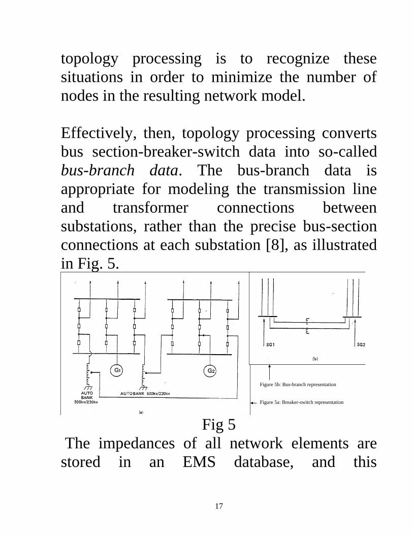
Effectively, then, topology processing converts
bus section-breaker-switch data into so-called
bus-branch data. The bus-branch data is
appropriate for modeling the transmission line
and transformer connections between
substations, rather than the precise bus-section
connections at each substation [8], as illustrated
in Fig. 5.
Figure 5b: Bus-branch representation
Figure 5a: Breaker-switch representation
Fig 5
The impedances of all network elements are
stored in an EMS database, and this

18
information, when combined with the output of
the topology processor, is enough to establish
the system topology.
State Estimation: Given the topology of the
system, it still remains to determine the
operating conditions, i.e., the bus voltages, load
levels, and generation levels. At first glance, this
appears to be an easy problem – just take the
corresponding information from the SCADA.
However, one must recognize the reality of data
unavailability and of data error.
Data unavailability comes from two sources.
First, there may be some substations that have
no SCADA. Second, there may be some
substation RTUs or telemetry systems that are
unavailable due to maintenance or unexpected
trouble.
Data error comes from the fact that all analog
measurement devices contain some
measurement error. Typically this error is small
19
for any single device, but the use of many
thousands of devices, each having small error,
can result in significant inaccuracy in regards to
the overall system analysis. The state estimator
is a program that receives the SCADA
measurement information and then uses
statistical procedures to obtain the very best
estimate of the actual state of the system. The
result of state estimation is a power flow model
that can be used for security assessment.
2.3.2 Security Assessment Security assessment determines first, whether the
system is currently residing in an acceptable state
and second, whether the system would respond in
an acceptable manner and reach an acceptable
state following any one of a pre-defined
contingency set. A contingency is the unexpected
failure of a transmission line, transformer, or
generator. Usually, contingencies result from
occurrence of a fault, or short-circuit, to one of
these components. When such a fault occurs, the
protection systems sense the fault and remove the
20
component, and therefore also the fault, from the
system.
Of course, with one less component, the overall
system is weaker, and undesirable effects may
occur. For example, some remaining circuit may
overload, or some bus may experience an
undervoltage condition. These are called static
security problems.
Dynamic security problems may also occur,
including uncontrollable voltage decline,
generator overspeed (loss of synchronism), or
undamped oscillatory behavior.
Almost all EMS today are capable of
performing static security assessment, because it
only requires a power flow program to do so.
Very few EMS are capable of performing
dynamic security assessment, however, because
the assessment tools are more complex and
computationally intense. However, dynamic
security assessment tools are rapidly becoming
21
more prevalent in EMS with the continued
growth in computational and algorithmic
efficiency.
2.3.3 Automatic Generation Control
As we have seen already in this course, the
purpose of AGC is to regulate the system
frequency and power interchange between
control areas.
There are two SCADA measurement used by
AGC: total net tie line flow and frequency.
There also exist scheduled values for these two
parameters. The scheduled net tie line flow
depends on the total sales less purchases to other
control areas. The scheduled frequency is
always 60 Hz. The differences between actual
and scheduled tie line flow and frequency can
be denoted as Ptie and f, respectively. These
two values are combined in a weighted sum
Ptie+Bf and provided as the AGC control
actuation signal. If this signal is positive, it
22
means that either our control area is selling too
much power or the frequency is too high. In
either case, the solution is to reduce generation
within our control area, and “lower” command
pulses are consequently sent to all generators. If
the control actuation signal is negative, it means
that either our control area is buying too much
power or the frequency is too low. In either
case, the solution is to increase generation
within our control area, and “raise” command
pulses are consequently sent to all generators.
AGC typically sends the appropriate command
pulses to the generators every 1-5 minutes.
It is important to recognize that the command
pulses sent to each generator represent
incremental changes only. This leaves the
question: What should be the set point power
levels at the generators?
2.3.4 Economic Dispatch
Previous to the power industry restructuring, all
ECCs used economic dispatch calculation
23
(EDC) to determine the set point power levels of
all generators in order to supply the demand.
Such a system still exists in some parts of the
country. But in other parts, a market dispatch is
done based on an auction system whereby the
optimization algorithm is similar to EDC except
generator cost-rate curves are replaced by
generator owner bids. We have already studied
the EDC problem and solution procedure.
One also observes in Figure 3 the acronym
“SCED,” which stands for security-constrained
economic dispatch. The SCED is also an
optimization problem. It is similar to EDC in
that it typically has the same objective of
minimizing the total cost of generation in order
to supply the demand. Yet it extends the EDC to
account for the equality constraints governing
the real and reactive power flowing out of each
bus and therefore, its optimal solutions are more
realistic. More important, it offers the capability
to determine the effects of different electrical
constraints on the system economic operation.
24
The security constrained aspect of the SCED
accounts for flow constraints imposed by
security considerations identified through
contingency analysis.
References 0. http://www.nerc.com/AboutNERC/keyplayers/Pages/default.aspx
1. V. Sudhakar Ganugula, Parallelization of On-Line Risk Based Security Assessment Application, M.S. Thesis,
Iowa State University, January, 2001.
2. R. Miller, Power System Operation, second edition, McGraw-Hill, New York, 1983.
3. G. Kusic, Computer Aided Power System Analysis, Prentice-Hall, Englewood Cliffs, NJ, 1986.
4. H. Rustebakke, editor, Electric Utility Systems and Practices, fourth edition, John Wiley & Sons, New York,
1983.
5. M. Sterling, Power System Control, Peter Peregrinus, LTD, London, 1978.
6. “The New IEEE Standard Dictionary of Electrical and Electronics Terms,” fifth edition, IEEE, 1993.
7. D. Marihart, “Communications Technology Guidelines for EMS/SCADA Systems,” IEEE Transactions on
Power Delivery, Vol. 16, No. 2, April, 2001, pp. 181-188.
8. A. Monticelli, State Estimation in Electric Power Systems, A Generalized Approach, Kluwer, Boston, 1999.
9. A. Moser, G. Ejebe, J. Frame, “Network and Power Applications for EMS within a Competitive Environment,”
Proceedings of the IEEE Power Engineering Society Transmission and Distribution Conference, pp. 280-285,
1999.
10. C. Gonzalez-Perez, “Information Systems Supporting Electric Energy Deregulation in North
America,” presentation at the 2002 IEEE Summer Meeting, Chicago, July 2002, with
permission from Open Access Technology, Incorporated.