Embed Size (px)
Citation preview

ENERGY-BASED CONTROL OF THEBUTTERFLY ROBOT
Massimo Cefalo Leonardo Lanari Giuseppe Oriolo
Dipartimento di Informatica e SistemisticaUniversita di Roma “La Sapienza”
Via Eudossiana 18, 00184 Roma, Italycefalo,lanari,[email protected]
Abstract: We address the control problem for the Butterfly, an interesting exampleof 2-dof underactuated mechanical system. This robot consists of a butterfly-shaped rotational link on whose rim a ball rolls freely. The control objective isto stabilize the robot at a certain unstable equilibrium. To this end, exploitingthe existence of heteroclinic trajectories, we extend a previously proposed energy-based technique. Simulation results show the effectiveness of the presented method.Copyright c©2006 IFAC
Keywords: Energy-based control, underactuated systems, heteroclinic orbits
1. INTRODUCTION
In recent years, a remarkable effort has been de-voted to the study of underactuated robots, i.e.,mechanical systems with less control inputs thangeneralized coordinates. This class encompassesmany interesting robotic devices, including min-imalistic manipulation devices, elastic manipula-tors, underwater vehicles, and biped robots.
The Butterfly robot considered in this paper wasintroduced in (Lynch et al., 1998) for the study ofnon-prehensile manipulation tasks. Other closelyrelated systems are the Ball and Beam (Hauser etal., 1992), the Acrobot (Spong, 1995) and the Pen-dubot (Spong and Block, 1995). Among the differ-ent available approaches, control techniques basedon passivity and energy concepts have recentlybeen extended to underactuated mechanical sys-tems; see for example (Ortega et al., 2002; Grizzleet al., 2005).
With reference to the problem of stabilizing theButterfly at a certain unstable equilibrium, wepresent in this paper the extension of an energy-based control technique introduced for the Pen-
dubot in (Fantoni et al., 2000) and subsequentlyrefined in (Kolesnichenko and Shiriaev, 2002). Theresulting controller combines a swing-up phase,aimed at approaching a heteroclinic trajectory,with a balancing phase designed on the linearapproximation of the system.
The paper is organized as follows. Section 2 de-scribes the Butterfly robot, while the existence ofheteroclinic orbits is analyzed in Section 3. Theproposed energy-based controller is presented inSection 4, and its stability properties are analyzedin Section 5. Simulation results for a laboratoryprototype which is currently being instrumentedare presented in Section 6.
2. THE BUTTERFLY
The Butterfly is a two-dof planar robotic mech-anism, originally conceived to analyze the role ofshape in dynamic (non-prehensile) manipulationtasks (Lynch et al., 1998). As shown in Fig. 1, thesystem consists of a butterfly-shaped rotationallink over whose rim a ball is free to roll. In par-
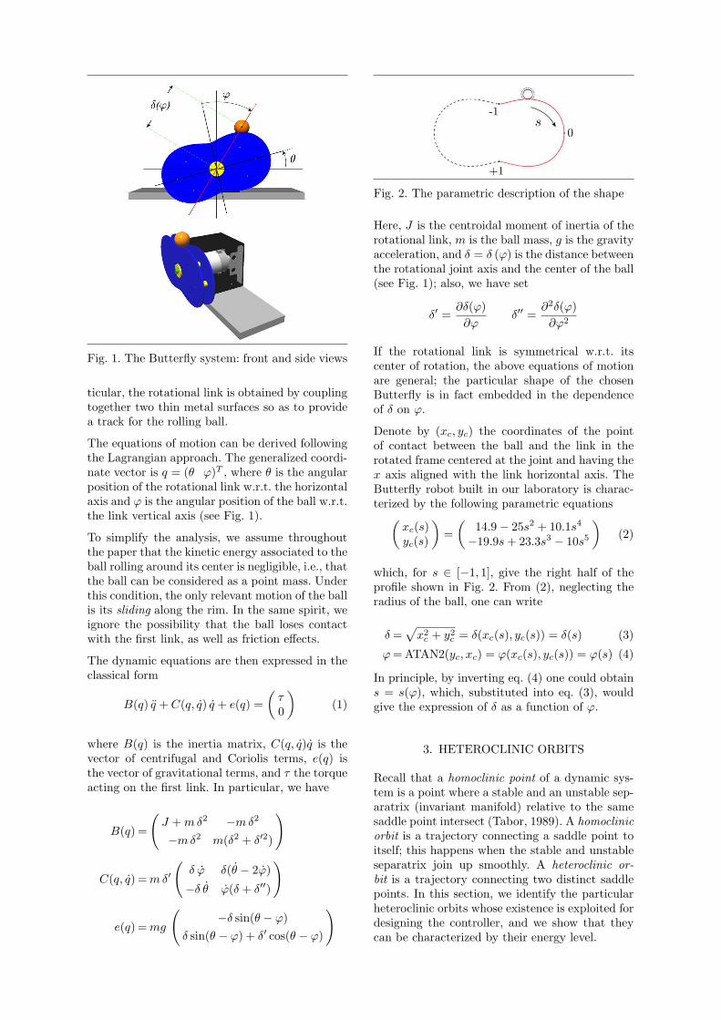
Fig. 1. The Butterfly system: front and side views
ticular, the rotational link is obtained by couplingtogether two thin metal surfaces so as to providea track for the rolling ball.
The equations of motion can be derived followingthe Lagrangian approach. The generalized coordi-nate vector is q = (θ ϕ)T , where θ is the angularposition of the rotational link w.r.t. the horizontalaxis and ϕ is the angular position of the ball w.r.t.the link vertical axis (see Fig. 1).
To simplify the analysis, we assume throughoutthe paper that the kinetic energy associated to theball rolling around its center is negligible, i.e., thatthe ball can be considered as a point mass. Underthis condition, the only relevant motion of the ballis its sliding along the rim. In the same spirit, weignore the possibility that the ball loses contactwith the first link, as well as friction effects.
The dynamic equations are then expressed in theclassical form
B(q) q + C(q, q) q + e(q) =(
τ0
)(1)
where B(q) is the inertia matrix, C(q, q)q is thevector of centrifugal and Coriolis terms, e(q) isthe vector of gravitational terms, and τ the torqueacting on the first link. In particular, we have
B(q) =
(J + m δ2 −m δ2
−m δ2 m(δ2 + δ′2)
)
C(q, q) = m δ′
(δ ϕ δ(θ − 2ϕ)
−δ θ ϕ(δ + δ′′)
)
e(q) = mg
(−δ sin(θ − ϕ)
δ sin(θ − ϕ) + δ′ cos(θ − ϕ)
)
Fig. 2. The parametric description of the shape
Here, J is the centroidal moment of inertia of therotational link, m is the ball mass, g is the gravityacceleration, and δ = δ (ϕ) is the distance betweenthe rotational joint axis and the center of the ball(see Fig. 1); also, we have set
δ′ =∂δ(ϕ)∂ϕ
δ′′ =∂2δ(ϕ)∂ϕ2
If the rotational link is symmetrical w.r.t. itscenter of rotation, the above equations of motionare general; the particular shape of the chosenButterfly is in fact embedded in the dependenceof δ on ϕ.
Denote by (xc, yc) the coordinates of the pointof contact between the ball and the link in therotated frame centered at the joint and having thex axis aligned with the link horizontal axis. TheButterfly robot built in our laboratory is charac-terized by the following parametric equations(
xc(s)yc(s)
)=(
14.9− 25s2 + 10.1s4
−19.9s + 23.3s3 − 10s5
)(2)
which, for s ∈ [−1, 1], give the right half of theprofile shown in Fig. 2. From (2), neglecting theradius of the ball, one can write
δ =√
x2c + y2
c = δ(xc(s), yc(s)) = δ(s) (3)
ϕ = ATAN2(yc, xc) = ϕ(xc(s), yc(s)) = ϕ(s) (4)
In principle, by inverting eq. (4) one could obtains = s(ϕ), which, substituted into eq. (3), wouldgive the expression of δ as a function of ϕ.
3. HETEROCLINIC ORBITS
Recall that a homoclinic point of a dynamic sys-tem is a point where a stable and an unstable sep-aratrix (invariant manifold) relative to the samesaddle point intersect (Tabor, 1989). A homoclinicorbit is a trajectory connecting a saddle point toitself; this happens when the stable and unstableseparatrix join up smoothly. A heteroclinic or-bit is a trajectory connecting two distinct saddlepoints. In this section, we identify the particularheteroclinic orbits whose existence is exploited fordesigning the controller, and we show that theycan be characterized by their energy level.

Fig. 3. The desired unstable equilibrium points
Consider the two equilibrium points
(qdes
qdes
)=
0
±ϕdes
00
(5)
where ±ϕdes are the symmetric angular positionsof the ball shown in Fig. 3. Such equilibria areunstable and in particular they are saddle points.
Denoting by K(q, q) the kinetic energy and byU(q) the potential energy, the total energy of thesystem is given by
E(q, q) = K(q, q) + U(q)
=12qT B(q)q + mgδ cos(θ − ϕ)
The above equilibrium points achieve the maximalpotential energy compatible with the rotationallink being horizontal. In particular, the energy atthese points is
Edes = E(qdes, qdes) = U(qdes)
A fundamental observation 1 for our control de-sign is that, if the Butterfly link is held horizontal(i.e., if θ(t) ≡ 0), any trajectory starting at a pointwhere E = Edes will converge (depending on thesign of the initial ϕ) to one of the equilibriumpoints (5) . This is clearly shown by the phaseportrait for θ(t) ≡ 0 reported in Fig. 4 (equiva-lently, we may say that this is the phase portraitfor the zero dynamics corresponding to the outputθ). Therefore, the heteroclinic orbits of interest arethe two non-trivial system trajectories for which
θ(t) ≡ 0 and E(q, q) = Edes (6)
Note that each heteroclinic orbit tends to one ofthe two unstable equilibria (see Fig. 4).
1 This behavior is similar to that of the Pendubot whenthe first link is kept vertical and the system is initialized at
an energy level corresponding to the upward unstable equi-librium (Fantoni et al., 2000). In that case, the resulting
trajectories are exactly the homoclinic orbits of a simple
pendulum.
Fig. 4. The Butterfly phase portrait for θ(t) ≡ 0
4. CONTROLLER DESIGN
In the sequel, an energy-based control approachis used to solve a set-point regulation problem.In particular, starting from any initial state, theButterfly is to be stabilized at one of the twounstable equilibrium points (5).
As common in this kind of problems, a two-phasecontrol approach is used. In the first phase (swing-up), the controller brings the system toward thetwo heteroclinic orbits implicitly defined by (6).Since the controller is energy-based, it does notdistinguish between the two trajectories: indeed,the state will alternately approach both the de-sired equilibria (5) with increasing accuracy. Inthe second phase (balancing), the control switchesto a locally stabilizing controller. For example, anLQR controller designed on the linearization ofthe system about the chosen desired equilibriumpoint can be used. In the following we focus onthe design of the swing-up phase.
In order to bring the system trajectories to theheteroclinic orbits defined by eq. (6), the followingpositive semi-definite Lyapunov function is con-sidered
V (q, q) =12Ke(∆E)2 + +
12Kdθ
2 +12Kpθ
2
with ∆E = E(q, q)−Edes and Ke, Kd, Kp strictlypositive constants. The time derivative of V is
V = Ke ∆E E + Kd θ θ + Kp θ θ (7)
Using the passivity property of the mechanismfrom τ to θ
E = qT
(τ0
)= θ τ
eq. (7) can be rewritten as
V = θ(Ke ∆E τ + Kd θ + Kp θ
)(8)
Using the dynamic equations (1) for θ and letting

detB = m(Jδ2 + Jδ2 + mδ2δ2
)h = m2δδ′
[g(δ′sin(θ − ϕ)− δcos(θ − ϕ)) +
+(δ2 + 2δ′2 − δδ′′)ϕ2 + δ2θ2 − 2(δ2 + δ′2)θϕ]
eq. (8) becomes
V = θ
[(Ke∆E +
Kdb22
det B
)τ + Kpθ +
Kdh
detB
]
where b22 = m(δ2 + δ′2) is the (2, 2) element ofthe inertia matrix B. Choosing the input as
τ =− det B
detB Ke ∆E + Kdb22·(
Kθ + Kpθ +Kdh
det B
)(9)
with K > 0, leads to a negative semi-definite V
V = −Kθ2 (10)
To avoid singularities in the control law (9), itmust be
detB Ke ∆E + Kdb22 6= 0 (11)
Since det B and b22 are positive, eq. (11) is satis-fied if
|∆E| 6= Kd
Ke
b22
detB
Defining
b22min = minϕ
b22(ϕ) det Bmax = maxϕ
detB(ϕ)
eq. (11) is clearly satisfied if the following inequal-ity is verified for some ε > 0
|∆E| ≤ Kd
Ke
b22min
detBmax− ε (12)
Under constraint (12), which in turn entails acondition involving the initial state and the gainsKd, Ke, the control law (9) is well defined.
5. STABILITY ANALYSIS
Since V is only negative semi-definite, the stabilityanalysis is based upon LaSalle’s invariance princi-ple (Khalil, 1996). Being V nonincreasing, θ, θ andϕ are bounded. Moreover, the system trajectoriesare also bounded and remain inside a compactset Ω that depends on the initial state. Let Γ bethe set of points in Ω where V = 0, and M bethe largest invariant set in Γ. LaSalle’s invarianceprinciple states that every solution starting in Ωapproaches M as t →∞.
For the Butterfly, we have Γ = (q, q) ∈ Ω : θ = 0and hence
M = (q, q) ∈ Γ : θ = 0, θ = 0
Comparing eqs. (8) and (10) the control torque onM satisfies
Ke ∆E τ + Kp θ = 0 (13)
Moreover, since on M it is E(q, q) = θ τ = 0,it follows that E(q, q) = cost. We can have twodifferent cases, E(q, q) = Edes and E(q, q) 6= Edes.
If ∆E = 0 (i.e., E(q, q) = Edes), it follows fromeq. (13) that θ(t) ≡ 0; therefore, the closed-loopsystem is evolving along one of the heteroclinicorbits defined by eq. (6).
In the second case we have E(q, q) = E∗ 6= Edes.From eq. (13), defining ∆E∗ = E∗−Edes, one hasthat τ = τ∗ = −kpθ
∗/Ke∆E∗. This implies thatthe ball must be also at rest, since otherwise anon-constant torque would be needed to keep therigid body at rest. Therefore the only additionalstates which can potentially belong to M , areequilibrium points (θ∗ ϕ∗ 0 0)T such that
e(θ∗, ϕ∗) =(
τ∗
0
)or, more explicitly
Kpθ∗
Ke∆E∗ = mgδ(ϕ∗) sin(θ∗ − ϕ∗)
δ(ϕ∗) sin(θ∗− ϕ∗) + δ′(ϕ∗) cos(θ∗− ϕ∗) = 0(14)
To find out if these additional equilibria exist,it is necessary to analyze (14). From the secondequation, we get
θ∗ = ϕ∗ + arctan(−δ′(ϕ∗)
δ(ϕ∗)
)which, plugged into the first one, leads to arelationship of the form
Kpf1 (ϕ∗) = Kef2 (ϕ∗) (15)
Note that, up to now, the specific form of theprofile δ = δ(ϕ) has not been used. For ourButterfly prototype, no closed form is available forδ, and therefore the solutions of eq. (15) must befound numerically. Figure 5 shows in red (dashedlines) the family of curves Kef2(ϕ) when Ke
varies, and in blue (continuous lines) the familyof curves Kpf1(ϕ) when Kp varies.
For any choice of Kp and Ke, as shown in Figure 5,there always exist at least three solutions, corre-sponding to the desired equilibrium states (5) andthe origin. Note also that for any fixed value of Ke

-150 -100 -50 0 50 100 150-3
-2
-1
0
1
2
3
-180 18090-90
Fig. 5. Equation (15): curves representing the lhsand rhs when Kp and Ke vary.
(Kp) it is always possible to avoid other solutionsby choosing Kp high enough (Ke low enough).
It is then necessary to seek conditions under whichthe equilibrium point at the origin is avoided. Tothis end, it is sufficient to require that at all timeinstants
|∆E| < ∆E = |Edes − E0|
where E0 is the energy of the Butterfly at theorigin. Putting this together with the sufficientcondition (12) for the control input to be welldefined, we conclude that at all time instants ∆Emust be such that
|∆E| < γ = min(
∆E,Kdb22min
Ke detBmax− ε
)(16)
Since V is nonincreasing, we can write
12Ke |∆E|2 ≤ V (t) ≤ V (0)
so that eq. (16) is certainly satisfied provided that
V (0) ≤ Keγ2
2(17)
In conclusion, if the initial conditions are chosen 2
so as to satisfy eq. (17), the closed-loop systemtrajectories will converge to the set M given bythe heteroclinic orbits. In general, the Butterflywill perform growing oscillations, which will leadthe system state to alternately approach boththe equilibria (5) with increasing accuracy. In theparticular case that the initial state belongs toone of the two heteroclinic orbits, no oscillationoccurs and the system monotonically approachesthe corresponding equilibrium point.
If one of the two equilibria (5) is specificallyassigned as set-point, the balancing controller
2 Note that the origin is not an admissible initialization.
Fig. 6. The Butterfly experimental set-up
must be designed so as to capture (by properswitching) and stabilize the Butterfly around thechosen point. In view of the above discussion,initial states along the ‘wrong’ heteroclinic orbitmust be avoided (in addition to the origin).
We mention that the proof of (Fantoni et al.,2000), that has been closely followed in this paper,has been modified in (Kolesnichenko and Shiri-aev, 2002) where less stringent conditions on thecontroller parameters have been presented. Thelack of an explicit dependence of δ from ϕ preventsthe use of such a result in this context.
6. SIMULATION RESULTS
We remind the reader that the model presentedin Section 2 is valid only if the contact betweenthe ball and the Butterfly is not lost. The numericsimulator used in our analysis includes a test onthe contact conditions.
The system parameters, computed from a CADmodel of the prototype built in our lab (seeFig. 6), are J = 0.853 10−2 kg m2 and m =0.15 kg. The controller gains are Kp = 1000,Kd = 10, Ke = 10000 and K = 100. Theinitial state is ( 0 10 0 0 )T ; i.e., the Butterflyis horizontal and at rest while the ball starts atϕ(0) = 10 with zero velocity. The desired set-point is ( 0 ϕdes 0 0 )T .
Figures 7 and 8 show, respectively, the evolutionof (θ, θ) and (ϕ, ϕ). As a result of the stabilizationto the energetic level of the heteroclinic orbits,the control input injects energy into the systemso as to make the ball oscillate with increasingamplitude, until the trajectory enters the basin ofattraction of the linear controller. Note how thisis obtained with a very limited oscillation of thefirst link. Figure 9 shows how, during the swing-upphase, the energy asymptotically converges to thedesired value while the Lyapunov function goes tozero.

0 4 10 16 20- 20
0
20
t
(deg
)
4 16- 30
0
30
t
(deg
/s)
0 10 20
µµ.
Fig. 7. Simulation: evolution of θ and θ
0 4 10 16 20- 40
0
40
t
(deg
)
0 4 10 16 20- 400
0
400
t
(deg
/s)
''.
Fig. 8. Simulation: evolution of ϕ and ϕ
0 4 8 12 160.135
0.14
0.15
0.155
0 4 8 120
0.2
0.8
1
V(t)
t
t
E(t)
16
Fig. 9. Simulation: evolution of E and V
At t = 16.7 sec the state is sufficiently close to thedesired set-point, so that the balancing controlkicks in. Note the sudden change in θ at theswitching instant, due to particular choice of gainsin the LQR design.
7. CONCLUSIONS
We have studied a particular control problem forthe Butterfly, an example of 2-dof underactuatedmechanical system of interest in nonprehensilemanipulation. The specific objective is to stabilizethe robot at certain unstable equilibria. Relying
on the existence of heteroclinic trajectories con-verging to such equilibria, an energy-based con-trol technique has been proposed which extendprevious results obtained for the Pendubot sys-tem . Simulation results have been presented toshow the effectiveness of the method. Currentwork includes the vision-based implementationand experimental validation of our approach ona laboratory prototype.
REFERENCES
Fantoni, I., R. Lozano and M.W. Spong (2000).Energy based control of the Pendubot. IEEETransactions on Automatic Control 45, 725–729.
Grizzle, J.W., C.H. Moog and C. Chevallereau(2005). Nonlinear control of mechanical sys-tems with an unactuated cyclic variable.IEEE Transactions on Automatic Control50, 559–576.
Hauser, J., S. Sastry and P. Kokotovic (1992).Nonlinear control via approximate input-output linearization: the ball and beam exam-ple. IEEE Transactions on Automatic Con-trol 37, 392–398.
Khalil, H.K. (1996). Nonlinear Systems. PrenticeHall.
Kolesnichenko, O. and A.S. Shiriaev (2002).Partial stabilization of underactuated euler-lagrange systems via a class of feedbacktransformations. Systems & Control Letters45, 121–132.
Lynch, K.M., N. Shiroma, H. Arai and K. Tanie(1998). The roles of shape and motion in dy-namic manipulation: The butterfly example.In: IEEE Int. Conf. on Robotics and Automa-tion. pp. 1958–1963.
Ortega, R., M.W. Spong, F. Gomez-Estern andG. Blankenstein (2002). Stabilization of aclass of underactuated mechanical systemsvia interconnection and damping assignment.IEEE Transactions on Automatic Control47, 1218–1233.
Spong, M.W. (1995). The swing up control prob-lem for the Acrobot. IEEE Control SystemsMagazine 1, 49–55.
Spong, M.W. and D.J. Block (1995). The Pen-dubot: a mechatronic system for control re-search and education. In: 34th IEEE Conf.on Decision and Control. pp. 555–556.
Tabor, M. (1989). Chaos and integrability in non-linear dynamics. New York: Wiley.