Embed Size (px)
Citation preview

Energy and Helicity Budget of Four Solar Flares and Associated Magnetic
Clouds.
Maria D. Kazachenko, Richard C. Canfield, Dana Longcope, Jiong Qiu
Montana State University
CMEs
Quiet sun
structures
Active region
s
Coronal Mass Ejections (CME)
ICMEs
Non-Cylindri
cal structur
es
Magnetic
clouds
(MC)
Magnetic
clouds
(MC)
Active region
s
>1/3
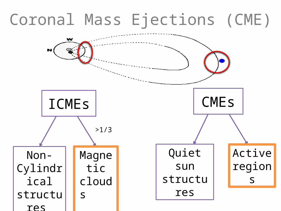
Physical properties: CME vs MC
?
Compare! MC physical properties:• axis orientation• magnetic flux• helicity
CME • axis orientation• magnetic flux• helicity
magnetic energy
radiated energy loss
GOESModeled

• Fast magnetic reconnection during flare
CME: flux rope formation
To model CME flux rope properties we need to understand
When are the flux ropes formed?
Before flare Pre-
existing• Emerge twisted• Formed by slow pre-flare magnetic reconnectionLow (1994), Fan & Gibson (2004), Leka et al.
(1996), Abbett & Fisher (2003), van Ballegooijen & Martens (1989), Mackay and van Ballegooijen (2001), Forbes & Priest (1995), Antiochos et al. (1999), Lynch et al. (2004)
Moore & LaBonte 1980, Mikic & Linker 1994, Demoulin et al. 1996, 2002; Magara et al. 1997; Antiochos et al. 1999; Choe & Cheng 2000; Nindos & Zhange (2002), Qiu et al. (2007), Longcope (2007).
During flareFormed in-
situ
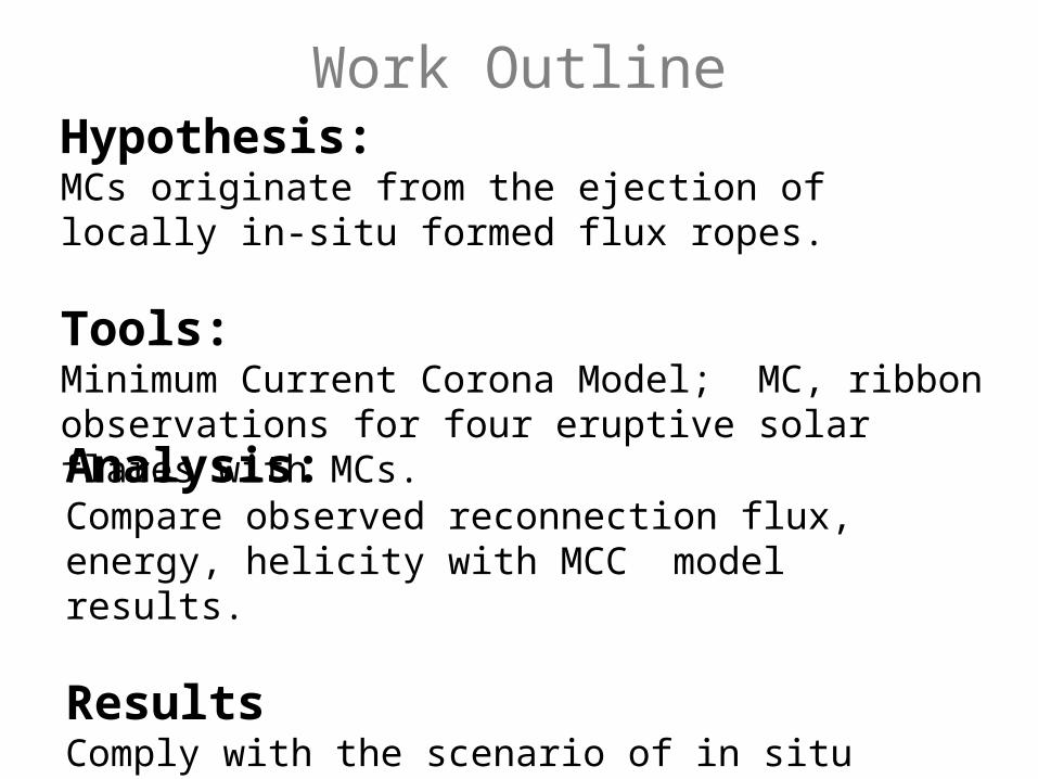
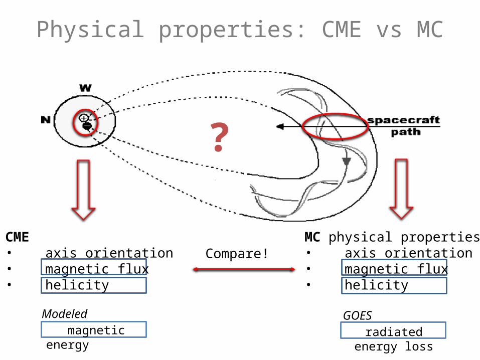
Hypothesis: MCs originate from the ejection of locally in-situ formed flux ropes.
Tools: Minimum Current Corona Model; MC, ribbon observations for four eruptive solar flares with MCs.Analysis:Compare observed reconnection flux, energy, helicity with MCC model results.
Results Comply with the scenario of in situ formed FR
Work Outline
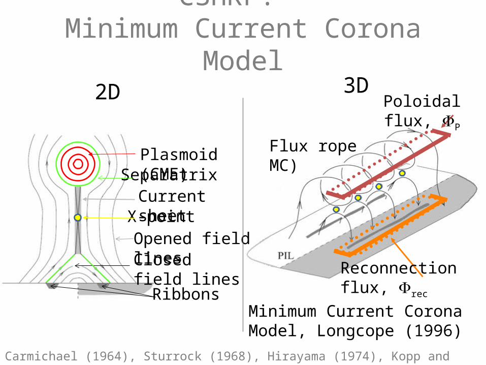
CSHKP. Minimum Current Corona
Model2D 3D
Closed field lines
X-pointCurrent sheet
Ribbons
Opened field lines
Plasmoid (CME)Separatrix
Flux rope MC)
Reconnection flux, rec
Poloidal flux, P
Carmichael (1964), Sturrock (1968), Hirayama (1974), Kopp and Pneuman (1976), Gosling (1990, 1995)
Minimum Current Corona Model, Longcope (1996)
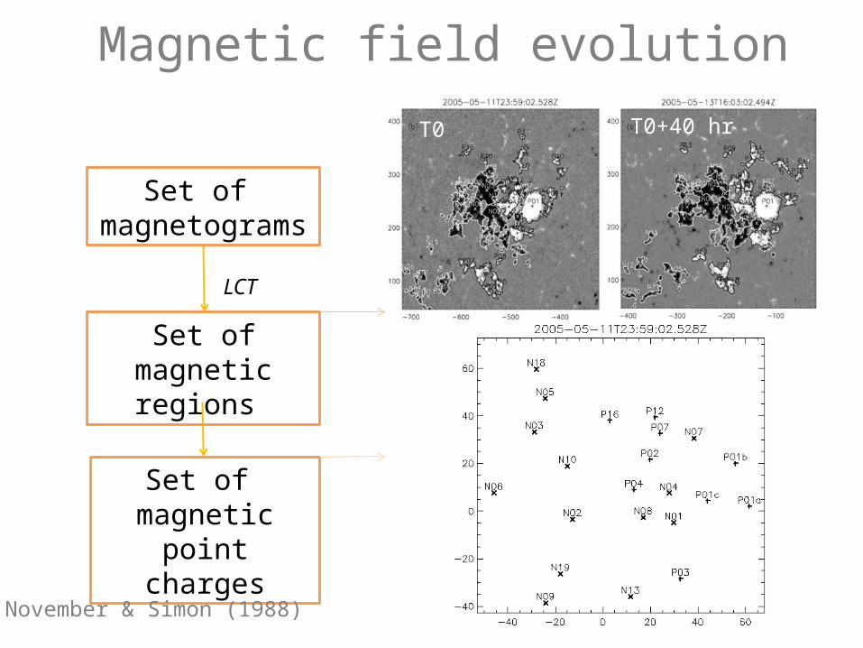
Magnetic point charge motions before May 13 2005 flare
Magnetic field evolution in 40 hr.
Magnetic field evolution
Set of magnetogram
s
Set of magnetic regions
Set of magnetic
point charges
LCT
T0 T0+40 hr
November & Simon (1988)
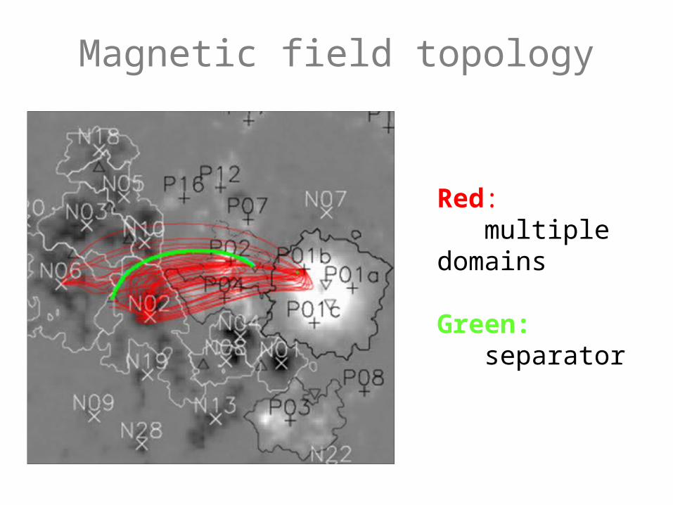
Magnetic field topology
Red: multiple domains
Green: separator
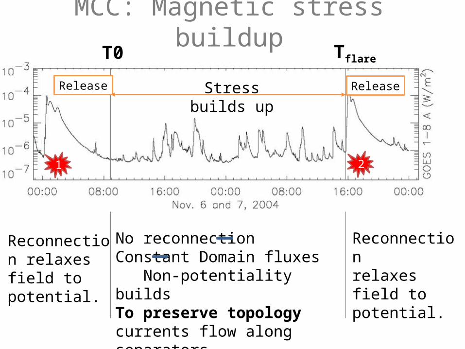
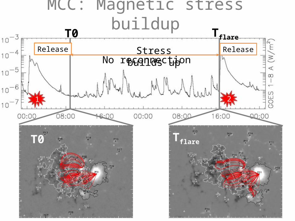
MCC: Magnetic stress buildup
1 2
Stress builds up
ReleaseRelease
No reconnection Constant Domain fluxes Non-potentiality buildsTo preserve topology currents flow along separators
Reconnection relaxes field to potential.
Reconnection relaxes field to potential.
T0 Tflare
MCC: Magnetic stress buildup
1 2
Stress builds upNo reconnection
ReleaseRelease
T0 Tflare
T0 Tflare
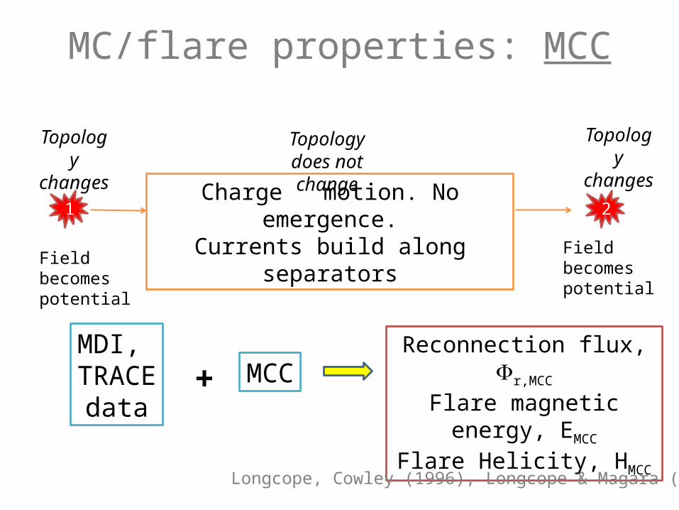
MC/flare properties: MCC
Charge motion. No emergence.
Currents build along separators
Reconnection flux, r,MCC
Flare magnetic energy, EMCC
Flare Helicity, HMCC
Topology does not change
1
Field becomes potential
2
Topology
changes
Field becomes potential
MCC
Topology
changes
MDI, TRACEdata
+
Longcope, Cowley (1996), Longcope & Magara (2004)
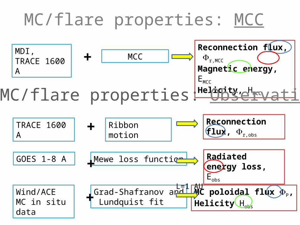
MC/flare properties: MCC
Wind/ACE MC in situ data
Grad-Shafranov and Lundquist fit
MC poloidal flux P,Helicity Hobs
GOES 1-8 A Mewe loss function Radiated energy loss, Eobs+
TRACE 1600 A
Reconnection flux, r,obs
Ribbon motion
+
+
L=1 AU
Reconnection flux, r,MCC
Magnetic energy, EMCC
Helicity, HMCC
MCCMDI, TRACE 1600 A +
MC/flare properties: Observations
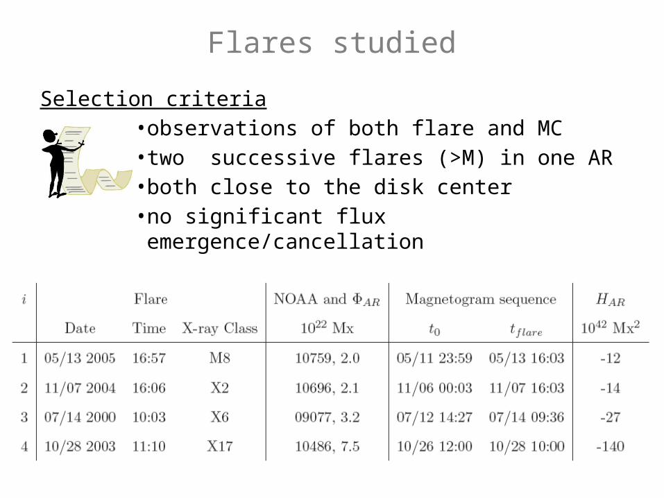
Flares studied
Selection criteria• observations of both flare and MC• two successive flares (>M) in one AR• both close to the disk center• no significant flux emergence/cancellation
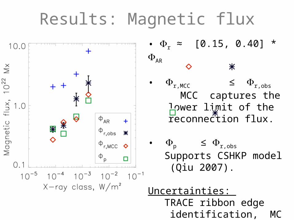
• r ≈ [0.15, 0.40] * AR
• r,MCC ≤ r,obs
MCC captures the lower limit of the reconnection flux.
• p ≤ r,obs
Supports CSHKP model (Qiu 2007).
Uncertainties: TRACE ribbon edge identification, MC fitting (MC length, boundaries)
Results: Magnetic flux
Results: Energy
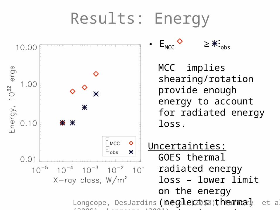
• EMCC ≥ Eobs
MCC implies shearing/rotation provide enough energy to account for radiated energy loss.
Uncertainties:GOES thermal radiated energy loss – lower limit on the energy (neglects thermal conduction and non-thermal energy).MCC model estimates minimum energy.
Longcope, DesJardins et al.(2010), Raftery et al. (2009), Longcope (2001)
Results: Magnetic Helicity
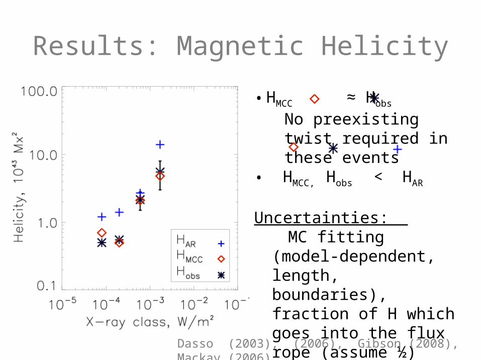
• HMCC ≈ Hobs
No preexisting twist required in these events
• HMCC, Hobs < HAR
Uncertainties: MC fitting (model-dependent, length, boundaries), fraction of H which goes into the flux rope (assume ½)
Dasso (2003), (2006), Gibson (2008), Mackay (2006)
ConclusionsMain purpose of the study:
Understand the FR formation and its relationship with the MC
Tool, DataMCC model + observations for four eruptive solar flares with
MCs
Results: In these four events, the MCC model is able to account for the observed reconnection flux, FR helicity and flare energy.
It suggests that:
FRs are formed in situ within the AR,
Flux emergence is relatively unimportant,
No preexisting twist is required.
Uncertainties: MC length, flux rope escape, total flare energy estimate.
Kazachenko et al. 2009, 2010

Acknowledgements• Richard Canfield, Dana Longcope,
Jiong Qiu, Angela DesJardins, Richard Nightingale, Qiang Hu, NASA.
Questions?
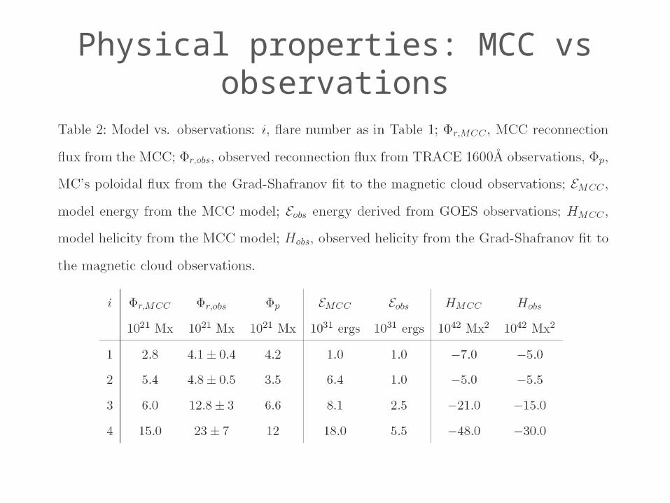
Physical properties: MCC vs observations