Embed Size (px)
Citation preview

Journal of the Mechanics and Physics of Solids51 (2003) 187–208
www.elsevier.com/locate/jmps
Energy absorption of an egg-box materialV.S. Deshpande, N.A. Fleck∗
Department of Engineering, Cambridge University, Trumpington Street, Cambridge CB2 1PZ, UK
Received 21 February 2002; accepted 3 June 2002
Abstract
Conical frustra made from leaded gun-metal have been compressed axially. Collapse is eitherby a travelling plastic hinge or by tearing. An analytical model is developed for the travellingplastic hinge in a rigid, ideally plastic solid; its predictions are compared with the observedresponse, and with those of an axisymmetric 4nite element analysis. The travelling hinge mech-anism is also observed in the compressive collapse of an egg-box material comprising a squarearray of conical frustra. Collapse mechanism maps are constructed for the egg-box material,and they show the regimes of dominance of elastic buckling, material tearing and the travellingplastic hinge. The maps are useful for selecting egg-box geometries that maximise the energyabsorption per unit mass at any prescribed value of collapse stress. The optimisation indicates thatthe egg-box material has a similar energy absorption capacity to that of hexagonal honeycombsand is superior to that of metal foams.? 2002 Elsevier Science Ltd. All rights reserved.
Keywords: Energy absorption; Tearing; Travelling plastic hinge; Elastic buckling; Compressive strength;Conical frustum
1. Introduction
In recent years a number of new micro-architectured materials have been developedfor the multi-functional design of lightweight structures. Lattice materials are peri-odic truss structures with a su9ciently large connectivity at each node to provide forstructural rigidity: under all applied loadings the individual struts deform by stretchingrather than by bending (Deshpande and Fleck, 2001; Deshpande et al., 2001; Wicksand Hutchinson, 2001). Consequently, the sti=ness and strength of lattice materialsscale linearly with their relative density >�.
∗ Corresponding author. Fax: +44-1223-332662.E-mail address: [email protected] (N.A. Fleck).
0022-5096/02/$ - see front matter ? 2002 Elsevier Science Ltd. All rights reserved.PII: S0022 -5096(02)00052 -2

188 V.S. Deshpande, N.A. Fleck / J. Mech. Phys. Solids 51 (2003) 187–208
Fig. 1. (a) Photograph of the egg-box material made by cold-pressing commercially pure aluminium. (b)Sketch of the cross-section of the egg-box material, from crown to adjacent trough. All dimensions are in mm.The solid line represents a unit cell of the egg-box material, and is a conical frustum with a hemisphericalcrown.
Lattice materials collapse in compression by the elastic buckling of struts at >�¡ 1%and by plastic yield at higher values of >�. Provided >�¡ 20% the struts are su9cientlyslender for the compressive collapse load to drop steeply in magnitude beyond the initialpeak value: this feature is not desirable in energy absorption. For relative densitieshigher than 20%, the struts are stocky and collapse at an almost constant load, makingfor high energy absorption. For many energy absorption applications a material of lowdensity is required and lattice materials are not the best choice. Instead, hexagonalhoneycombs, metal foams and egg-box materials are candidates; the geometry of theegg-box material used in the present study is shown in Fig. 1. Metal honeycombsare currently used for energy absorption within the cores of sandwich panels, whilemetal foams can be manufactured to complex near nett shape by powder metallurgicalmethods (Banhart, 2000). Egg-box material is potentially cheaper than lattice material,honeycomb or metal foam as it can be cold or hot stamped from a wrought sheet ina single step operation.

V.S. Deshpande, N.A. Fleck / J. Mech. Phys. Solids 51 (2003) 187–208 189
Hexagonal honeycombs give high energy absorption by the formation of a successionof folds of each cell, with hoop stretching of the cell wall between each fold. Theformation of each successive fold leads to large oscillations in the collapse stress. Incontrast, open-cell metal foams and the current generation of commercially producedclosed-cell metal foams absorb energy primarily by the bending of the cell edges atstationary plastic hinges. Again, Guctuations in the macroscopic stress versus straincurve are observed, but now the cause is the successive collapse of layers of the foam.In the current study, we investigate experimentally and theoretically the compressivecollapse of egg-box material in order to determine its ability to absorb energy. Weshall show that the primary mode of collapse is by a travelling plastic hinge withineach periodic cell of the egg-box. The same collapse mode is exhibited by a closed-topconical frustum, and so the study begins with an investigation of the axial compressiveresponse of a closed-top conical frustum.
2. Compressive behaviour of conical frustra
A number of researchers have investigated experimentally and theoretically the com-pressive collapse of open-top conical frustra, see for example Mamalis et al. (1986a, b).Collapse is by a variety of plastic folding mechanisms (axisymmetric or diamondpatterns) which resemble the collapse mechanisms of thin walled cylindrical shells.Alghamdi (2001) has recently reviewed these and related investigations. In this sectionwe investigate the compressive deformation behaviour of conical frustra with closedtops. Then in the following sections, the results for conical frustra are used to interpretthe transverse compressive collapse of egg-box material.
2.1. Experimental investigation
Conical frustra of geometry sketched in Fig. 2a, were machined from solid circularbars of leaded gun-metal of wt.% Cu-7Pb-7Sn-3Zn. Gun-metal was chosen as it hasa high tensile ductility of about 22%: tearing of the material is a potential failuremechanism as will be seen later in the paper. All specimens had a wall thicknesst = 1 mm and base diameter D = 35 mm. The transition in shape between the Gattop of radius a and the conical portion of the frustum was sharp, with a radius ofcurvature c on the order of microns. Four conical frustra, with a=2 and 5 mm and coneangles !=30◦ and 50◦, were manufactured and tested; the cone angle ! is de4ned inFig. 2a.Each conical frustum was compressed between parallel steel platens on a screw-driven
test machine. All tests were performed at a nominal macroscopic strain rate of 10−3 s−1.The applied load P and the relative displacement u of the platens were recorded andplotted in Fig. 2b. Two competing deformation modes were observed:
1. The specimen with a large cone angle ! = 50◦ and a small top a = 2:5 mm toreas it underwent plastic straining within the knuckle. After tearing, the specimen

190 V.S. Deshpande, N.A. Fleck / J. Mech. Phys. Solids 51 (2003) 187–208
Fig. 2. (a) Sketch of conical frustum and the loading arrangement. (b) Measured load versus displacementcurves for conical frustra made from leaded gun-metal.
deformed by the in-extensional plastic folding mechanism for open-top conical shellsas reported by Mamalis et al. (1986b).
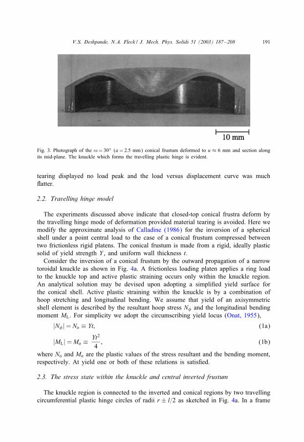
2. A travelling plastic hinge was observed in the remaining geometries. The character-istics of this travelling hinge are clear from the diametrical section of the specimenwith geometry !=30◦, a=2:5 mm and axial displacement u=6 mm, as shown inFig. 3. A circumferential knuckle forms the travelling plastic hinge and leads to theprogressive inversion of the conical frustum from its apex.
The three conical frustra that deformed by the travelling hinge mechanism showedan initial load peak associated with the initiation of the travelling hinge. The loaddropped over the ensuing 1 mm of axial displacement followed by an increase inload as the hinge propagated. On the other hand, the conical frustum that underwent
V.S. Deshpande, N.A. Fleck / J. Mech. Phys. Solids 51 (2003) 187–208 191
Fig. 3. Photograph of the != 30◦ (a= 2:5 mm) conical frustum deformed to u ≈ 6 mm and section alongits mid-plane. The knuckle which forms the travelling plastic hinge is evident.
tearing displayed no load peak and the load versus displacement curve was muchGatter.
2.2. Travelling hinge model
The experiments discussed above indicate that closed-top conical frustra deform bythe travelling hinge mode of deformation provided material tearing is avoided. Here wemodify the approximate analysis of Calladine (1986) for the inversion of a sphericalshell under a point central load to the case of a conical frustum compressed betweentwo frictionless rigid platens. The conical frustum is made from a rigid, ideally plasticsolid of yield strength Y , and uniform wall thickness t.Consider the inversion of a conical frustum by the outward propagation of a narrow
toroidal knuckle as shown in Fig. 4a. A frictionless loading platen applies a ring loadto the knuckle top and active plastic straining occurs only within the knuckle region.An analytical solution may be devised upon adopting a simpli4ed yield surface forthe conical shell. Active plastic straining within the knuckle is by a combination ofhoop stretching and longitudinal bending. We assume that yield of an axisymmetricshell element is described by the resultant hoop stress N and the longitudinal bendingmoment ML. For simplicity we adopt the circumscribing yield locus (Onat, 1955),
|N |= No ≡ Yt; (1a)
|ML|=Mo ≡ Yt2
4; (1b)
where No and Mo are the plastic values of the stress resultant and the bending moment,respectively. At yield one or both of these relations is satis4ed.
2.3. The stress state within the knuckle and central inverted frustum
The knuckle region is connected to the inverted and conical regions by two travellingcircumferential plastic hinge circles of radii r ± l=2 as sketched in Fig. 4a. In a frame

192 V.S. Deshpande, N.A. Fleck / J. Mech. Phys. Solids 51 (2003) 187–208
Fig. 4. The travelling hinge model. (a) sketch of the cross-section of the partially inverted frustum, (b) freebody diagram showing the cross-section of the inverted central region, (c) free body diagram of the knucklewith a unit circumference at radius r, and (d) free body diagram showing the plan view of a circumferentialsegment of the knuckle subtending a polar angle d at the centre.
of reference which moves with the toroidal knuckle, material enters the knuckle at theouter hinge and a longitudinal curvature is imposed; when material elements leave theknuckle by the inner hinge, this curvature is removed. Axisymmetric shell elementswithin the knuckle are subjected to a longitudinal bending moment ML that decreasesfrom +Mo at the outer plastic hinge to −Mo at the inner hinge, while the hoop bendingmoment vanishes throughout the knuckle. Since the equations of equilibrium requireML to vary continuously, we argue that |ML|¡Mo within the knuckle and so nochange in longitudinal curvature occurs between the two hinge circles. The toroidalknuckle rotates instantaneously about the outer hinge, and in order for the invertedconical frustum to be rigid, the entry and exit hinge-circles lie on the same horizontalplane as indicated in Fig. 4a. During an incremental rotation of the knuckle about theouter hinge each elemental hoop within the knuckle displaces with an inward radialcomponent. Thus, the knuckle undergoes compressive hoop straining and it follows

V.S. Deshpande, N.A. Fleck / J. Mech. Phys. Solids 51 (2003) 187–208 193
from the circumscribing yield locus that the hoop stress within the entire knuckleregion attains the compressive yield strength.Fig. 4b shows the stress resultants which act on the central inverted frustum. The
outer edge of inverted frustum is subjected to a longitudinal bending moment ML=−Mo.Vertical equilibrium of the inverted frustum dictates that the vertical component ofthe stress resultant on the outer edge of the inverted frustum equals zero. Also, thelongitudinal bending moment is a maximum on the outer edge since the outer edgeis at a moving plastic hinge. Consequently, the shear force vanishes and no stressresultants act on the outer edge of the inverted central frustum.
2.4. Equilibrium relations
The cross-section of the knuckle and the stress resultants that act on a segment ofunit circumference at radius r are sketched in Fig. 4c. The ends of the knuckle have aslope of ±!, and the pro4le of the knuckle is a circular arc of radius R. Geometricalconsiderations dictate that the height h of the knuckle and the elevation � of the centroidabove the plane of the hinge circles are given by
h= R(1− cos!) (2a)
and
�= R(sin!!
− cos!): (2b)
Upon assuming that l�r, equilibrium in the axial (vertical) direction gives
V =P2�r
; (3a)
where P is the total compressive force exerted by the rigid plates and V is the verticalforce per unit length at the outer hinge circle. At the outer hinge circle the forceresultant is tangential to the longitudinal direction since ML is a maximum at the hingecircle and thus it follows that the inner radial force per unit length H is
H =P
2�r tan!: (3b)
Now consider radial equilibrium of a segment of the knuckle subtending a small polarangle d as shown in Fig. 4d. The inward radial force balances the outward radialforce due to compressive hoop yield within the knuckle, to give
Hr d = 2YtR! d : (4)
Elimination of H from Eqs. (3b) and (4) gives
P = 4�YtR! tan!: (5)
In order to determine the knuckle radius R we consider moment equilibrium about thehoop direction. Recall that the stress resultants on a segment of the knuckle with unitcircumference at radius r are sketched in Fig. 4c. Then on taking moments about the

194 V.S. Deshpande, N.A. Fleck / J. Mech. Phys. Solids 51 (2003) 187–208
outer hinge, we obtain
Pl4�r
= 2Mo +2Yt!R2
r
(sin!!
− cos!)
(6)
and an explicit expression for R follows via (5) and the relation l= 2R sin!,
R=[
MorYt(2!− sin 2!)
]1=2: (7)
An expression for the compressive force P is obtained in terms of the current radiusr by combining Eqs. (5) and (7) to obtain
P =2�! tan!
(2!− sin 2!)1=2Yt3=2r1=2: (8)
For thin walled shells, it is reasonable to assume that the knuckle dimensions are muchsmaller than the axial displacement u of the rigid platen. Then the nominal compressivedisplacement u of the conical frustra is related to r through
r ≈ a+ u cot! (9)
and the load versus displacement relation of the conical shell can be expressed as
PYt2
=2�! tan!
(2!− sin 2!)1=2
[at+utcot!
]1=2: (10)
In some of the experiments described above, tearing was observed within the incipientknuckle. The longitudinal bending strain �L induced by the travelling knuckle is givenby
�L =t2R
=[
2!− sin 2!a=t + u=t cot!
]1=2: (11)
It is recalled that tearing occurred in the conical frustum of geometry ! = 50◦ anda=t = 2:5 made from gun-metal of ductility 22%. The maximum bending strain �L is55% by (11), and so tearing is anticipated.
2.4.1. Comparison of the model with 9nite element calculations and withmeasurementsThe accuracy of the analytical model is gauged in two steps. First, it is compared
with 4nite element (FE) calculations for an elastic, ideally plastic solid and second itis compared with the measured responses of the conical frustra made from gun-metal,as summarised in Fig. 2.The FE calculations were performed using the general purpose 4nite element package
ABAQUS (HKS, 1997) with the conical frustra modelled by about 320 axisymmetricquadratic shell elements (SAX2 element of ABAQUS). The base of the frustra wasconstrained to have no lateral displacements and no rotation. Loading was appliedthrough prescribed displacements of rigid loading platens, with the contact between theconical frustum and the rigid surfaces modelled by a frictionless contact surface as

V.S. Deshpande, N.A. Fleck / J. Mech. Phys. Solids 51 (2003) 187–208 195
provided by ABAQUS. J2 Gow theory was employed and the solid was taken to beelastic—perfectly plastic with a yield strain �Y = 0:1% and a Poisson’s ratio �= 0:3.A comparison between the load versus displacement curves from the FE calculations
and the analytical travelling hinge model is shown in Fig. 5a for cones (a=t=0) and inFig. 5b for conical frustra (a=t = 5). For the cones, the travelling hinge solution is ingood agreement with the FE calculations once a travelling hinge has become establishedat u=t ¿ 0:2. For the conical frustra both perfect and imperfect 4nite element geometriesare considered as follows:
1. Perfect conical frustra, with a sharp transition between the Gat top and the conicalshell and labelled as c = 0 in Fig. 5b. The FE calculations show an initial peak inthe load versus displacement response corresponding to initiation of the travellinghinge. After the travelling hinge has become established, the analytical travellinghinge solution agrees well with the FE calculations.
2. “Imperfect” frustra, with a local radius at the transition given by c=t = 1:7. The FEcalculations shown in Fig. 5b reveal that the initial load peak is now absent andadequate agreement is noted between the FE and rigid-plastic analytical calculationsfor u=t ¿ 0:5.
It is concluded that the travelling hinge model, despite its simplicity, gives an accu-rate description of the collapse of conical frustra made from an elastic perfectly plasticsolid.The second step in gauging the accuracy of the travelling hinge model is to compare
its predictions with the observed collapse response of the gun-metal frustra. To achievethis we measured the tensile stress versus strain behaviour of the leaded gun-metal, seeFig. 6a. The gun-metal has a yield strength of 170 MPa, an ultimate tensile strengthof 284 MPa and a tensile ductility of 22%. Comparisons between the measured loadversus displacement response of the conical frustra and the analytical travelling hingemodel are given in Fig. 6b for an assumed Gow strength Y =(170+284)=2=227 MPa.The comparisons are made only for the case a = 5 mm and ! = 30◦ and 50◦ asthese frustra did not tear. Reasonable agreement between the model predictions andthe experimental measurements is seen in light of the fact that the analytical modelneglects the e=ects of strain hardening.
3. Compressive behaviour of the egg-box material
Commercially pure (CP) aluminium sheets of thickness 1:0 mm were cold pressed 1
into an egg-box shape with overall dimensions 170 × 170 × 20 mm3 as shown inFig. 1a. The egg-box geometry can be approximated by a square array of conicalfrustra with each frustum of half the height of the egg-box material; the base diameterof the frustum is taken as the spacing between adjacent crowns of the egg-box. For
1 Cellbond Composites Ltd., 5 Stukeley Business Centre, Blackstone Road, Huntingdon PE29 6EF, UK(Ashmead, 2000).

196 V.S. Deshpande, N.A. Fleck / J. Mech. Phys. Solids 51 (2003) 187–208
Fig. 5. Comparison between the FE and travelling hinge model predictions of the load versus displacementresponse for: (a) cones with a=t =0, (b) conical frustra with a=t =5. In the FE calculations, the yield strain�Y was taken as 0.1%.

V.S. Deshpande, N.A. Fleck / J. Mech. Phys. Solids 51 (2003) 187–208 197
Fig. 6. (a) Measured tensile stress versus strain curve of the leaded gun-metal. (b) Comparison betweenthe measured load versus displacement response and the predictions of the rigid, perfectly plastic travellinghinge model (Y = 227 MPa) for conical frustra with a = 5 mm.

198 V.S. Deshpande, N.A. Fleck / J. Mech. Phys. Solids 51 (2003) 187–208
the manufactured egg-box, each frustum had a height of 10 mm and top cap and basediameters of 18 and 35 mm, respectively. The crowns of the egg-box were not Gat:they comprised hemispherical shells of radius R= 14 mm, as sketched in Fig. 1b.Prior to testing, the egg-box specimen was annealed for 4 h at 300◦C in an air
furnace to reduce the e=ects of the work-hardening of the solid material due to thecold-pressing. The compressive response of the egg-box specimen was measured withfull in-plane constraint: in-plane lateral expansion of the egg-box material was pre-vented by placing the specimen within a steel box with inner dimensions identicalto the projected plan dimensions of the egg-box specimen. The loading platens werecovered with PTFE tape to reduce friction, and the compression test was performedusing a screw driven test machine at a nominal strain rate of 10−3 s−1. The appliedload was measured by the load cell on the test machine and was used to de4ne thenominal compressive stress on the specimen; the nominal axial strain was measuredvia a clip gauge 4xed between the loading platens.The measured compressive stress versus strain response of the egg-box material is
shown in Fig. 7a. The stress versus strain curve comprises two regimes of behaviour:4rst, the stress increases gently with strain up to the densi4cation strain, and secondit rises steeply. A visual examination of the deformed specimen revealed that the de-formation mode in the 4rst regime involved the progressive inversion of the conicalfrustra, with the load transmitted from the rigid platens to the egg-box through circum-ferential knuckles. This closely resembles the travelling hinge mechanism discussedabove.In order to compare the measured response with FE calculations we measured the
uniaxial tensile response of the annealed CP aluminium sheet from which the egg-boxmaterial was cold-pressed; this curve is plotted in Fig. 7b. It was found that the CPaluminium had a yield strength Y ≈ 40 MPa, an ultimate tensile strength of about85 MPa and a tensile ductility of 20%. Axisymmetric 4nite element calculations wereperformed on the axial collapse of the unit cell shown in Fig. 1b. Details on the mesh,boundary conditions and the contact problem are the same as described above for theconical frustum. The solid was treated as an isotropic hardening J2 Gow theory solid,with the measured uniaxial tensile stress versus strain curve as reported in Fig. 7b anda Poisson’s ratio � = 0:3. The calculated stress versus strain response of the egg-boxmaterial is plotted as a dashed line in Fig. 7b and agrees very well with the measuredresponse of the egg-box material over the entire range of deformation. The FE analysisalso revealed that the mode of deformation resembled a travelling hinge mechanism.
3.1. Analysis of compressive deformation
It is of practical importance to develop analytical expressions for the collapse strengthand energy absorption capacity of the egg-box material. We proceed by making useof the travelling hinge model for the conical frustum. Consider an egg-box material ofdepth d made from a sheet of thickness t. The egg-box comprises a 2D square arrayof conical frustra, each with a top radius a and a cone angle !, see Fig. 1b. The baseof the unit cell for each frustum is assumed to be a square of side (2a + d cot!);thereby the unit cells 4ll space. The relative density >� of the egg-box material (ratio

V.S. Deshpande, N.A. Fleck / J. Mech. Phys. Solids 51 (2003) 187–208 199
Fig. 7. (a) Comparison between measured, travelling hinge model and FE predictions of the constrainedcompressive stress versus strain response of the egg-box material. In the insert all dimensions are in mm.(b) Measured tensile stress versus strain curve of the as-received commercially pure (CP) aluminium sheet.

200 V.S. Deshpande, N.A. Fleck / J. Mech. Phys. Solids 51 (2003) 187–208
of the density of the egg-box material to the density of the solid material from whichit is made) is given by
>�=�4>t
[cot!+ 4 >a>t + 4 >a2 >t2 sin!
sin!(2 >a>t + cot!)2
]; (12)
where >a= a=t and >t = t=d. Experimental measurements and FE simulations both showthat the mode of deformation of the egg-box material under constrained compressionresembles the travelling hinge mode discussed above. Thus, we proceed by employingthe travelling hinge model to estimate the compressive stress versus strain response ofthe egg-box material.
3.1.1. Travelling hinge deformation modeWe analyse the deformation of the egg-box material with the unit cell described
above and made from a rigid, perfectly plastic material of yield strength Y . Each unitcell contains a conical frustum, and the collapse stress � of the egg-box material isrelated to the axial load P by
� =P
(2a+ d cot!)2: (13)
Upon substituting for P from (10), the stress versus strain response of the egg-boxmaterial is
�Y
= k(>a+
�2>t
cot!)1=2
; (14a)
where � is the nominal axial strain and k a geometrical constant de4ned by
k =�! tan!
21
(2!− sin 2!)1=21
( >a+ cot!=2t)2: (14b)
We proceed by de4ning the densi4cation strain �D as the strain at which the invertedportion of the conical frustum makes 4rst contact with the lower rigid platen. Referringto Fig. 4a, the depth of the inverted region of the conical frustum below the planeof the hinge circles is given by
=(r − l
2− a)tan!: (15)
At densi4cation we have
R(1− cos!) + + 2u= d; (16)
where 2u is the relative displacement of the platens. Combining Eqs. (16) with (15),and noting that l= 2R sin! gives
R
(1− cos!− sin2 !
cos!
)+ (r − a) tan!+ 2u= d: (17)
With our assumption that the knuckle dimensions are much less than the magnitudeof the displacement u, we can neglect the 4rst term in the above equation. Upon

V.S. Deshpande, N.A. Fleck / J. Mech. Phys. Solids 51 (2003) 187–208 201
substituting for r from Eq. (9) we obtain
�D =23: (18)
This formula is not expected to be accurate for !�1 since the assumption R�u breaksdown.A comparison between the travelling hinge model predictions and the measured
stress versus strain response of the egg-box material is shown in Fig. 7a. It is recalledthat the actual geometry of the egg-box consists of a conical shell with a shallowhemispherical crown rather than a Gat top. For comparison with the analytical modelthe egg-box geometry is approximated by a conical frustum with a= 0 and ! = 40◦,as shown by the dashed line in the insert of Fig. 7a. The predicted stress versus strainresponse of the conical frustum is plotted in Fig. 7a for a yield strength Y =60 MPa. Itis truncated at the estimated densi4cation strain �D as stated by Eq. (18) and a verticalline indicates the sharply rising stress beyond the densi4cation strain. We conclude thatthe travelling hinge model and the predicted densi4cation strain are in good agreementwith the measured response.
3.1.2. Estimate of energy absorptionEnergy absorbers for packaging and crash protection are chosen so that they can
absorb energy at a stress level below a prescribed limit. We de4ne the energy absorptionper unit volume Wv as the area under the predicted nominal stress versus nominal straincurve for the egg-box material up to the densi4cation strain �D,
Wv =∫ �D
0� d�: (19)
Upon substituting (14a) into the above expression, we obtain
Wv
Y=
43k >t tan!
[(>a+
�D2>t
cot!)3=2
− >a3=2]; (20)
where k has already been de4ned by Eq. (14b). This is the energy absorbed per unitvolume with a maximum stress �D set by the stress at the densi4cation strain �D (�D isgiven explicitly by Eq. (14a) with �= �D = 2=3). The corresponding energy absorptionper unit mass is
Wm =Wv
>��s; (21)
where �s is the density of the sheet from which the egg-box material is made.
3.2. Collapse mechanism maps and energy absorption
The collapse of egg-box material under constrained compression is by (a) a travellingplastic hinge mechanism, (b) elastic buckling or (c) tearing. In order to determine howthe failure mode depends upon the geometry of the egg-box material we require anestimate of the elastic buckling stress for the egg-box material.

202 V.S. Deshpande, N.A. Fleck / J. Mech. Phys. Solids 51 (2003) 187–208
3.2.1. Elastic buckling of the egg-box materialThe egg-box material will collapse by elastic buckling when the elastic buckling
load is less than the load for a travelling plastic hinge. Recall that the elastic bucklingload Pc of a perfect conical shell is given by (Seide, 1956)
Pc =2�Et2 sin2 !√
3(1− �2): (22a)
For the case of a conical frustum, Seide (1956) modi4ed this formula to the form
Pact = CPc; (22b)
where the knock-down factor C is given by
C = 23:8(
sin!>a+ cot!=2>t
)0:66: (23a)
Thus, the elastic buckling stress of the egg-box is given by
�cY
= C�
2�Y√3(1− �2)
sin2 !( >a+ cot!=2>t )2
; (24)
where �Y is the yield strain of the solid material of the egg-box.
3.2.2. Construction of a collapse mechanism mapIt is assumed that the egg-box material collapses by elastic buckling if the buckling
stress �c is less than the densi4cation stress �D as predicted by the travelling plastichinge model. This can be shown graphically by plotting the collapse stress on a diagramwith non-dimensional axes ! and >� for selected values of >a=a=t. An example of sucha collapse mechanism map is given in Fig. 8 for >a = 4 and for the solid materialproperties � = 1=3 and �Y = 0:007. Tearing is assumed to occur if the longitudinalbending strain �L in the knuckle (11) exceeds the ductility of the solid material �f .This strain is a maximum in the early stages of deformation and we assume that thematerial will tear if �L¿ �f at u=0. Boundaries truncating the travelling hinge regimefor �f = 0:3 and 0.5 are included in the collapse mechanism map.In selecting materials for an energy absorption application it is common to maximise
the energy absorption per unit mass >Wm at a prescribed safe level of stress >�. To gaugethe capacity of the egg-box material to absorb energy at a given stress level we haveadded to Fig. 8 contours of the normalised energy per unit mass >Wm
>Wm =Wm�sY
(25)
and contours of normalised densi4cation stress >�=�D=Y . Both >Wm and >� increase alongthe leading diagonal of the map. We note that at a given stress level >�, the maximumenergy absorption >Wm is achieved along the boundary between the travelling hinge andtearing regimes.

V.S. Deshpande, N.A. Fleck / J. Mech. Phys. Solids 51 (2003) 187–208 203
Fig. 8. Deformation mechanism map for egg-box material with >a=4 (�Y =7× 10⁻³ and �=1=3). Contoursof the normalised densi4cation stress >� and the normalised energy absorption per unit mass >Wm are includedin the travelling plastic hinge deformation regime.
Fig. 9 shows the collapse mechanism map for >a = 10, with lines truncating thetravelling hinge regime due to tearing of the solid material for the choices �f = 0:2,0.3 and 0.5. Again it is evident that at any given stress level >�, the maximum energyabsorption >Wm is achieved along the boundary between the travelling hinge and tearingregimes.
3.2.3. Minimum weight designThe maximum energy absorption per unit mass >W
maxm is plotted in Fig. 10 as a
function of >�, for the selected values >a = 4 and 10, with �Y = 0:007, � = 1=3 and�f = 0:3. These curves correspond to boundaries of the travelling hinge and tearingregimes of Figs. 8 and 9. Fig. 10 includes estimates of >Wm for metal foams and metalhoneycombs loaded in the out-of-plane direction. We assume that the compressivestrength of the metal foam is given by Ashby et al. (2000)
�foamY
= 0:3 >�1:5; (26)
where Y is the yield strength of the fully dense metal and >� the relative density ofthe foam. Employing the same notation, the average axial collapse stress for hexagonalhoneycombs is given by Gibson and Ashby (1997)
�hcY
≈ 4:85 >�5=3: (27)

204 V.S. Deshpande, N.A. Fleck / J. Mech. Phys. Solids 51 (2003) 187–208
Fig. 9. Deformation mechanism map for egg-box material with >a=10 (�Y =7×10⁻³ and �=1=3). Contoursof the normalised densi4cation stress >� and the normalised energy absorption per unit mass >Wm are includedin the travelling plastic hinge deformation regime.
The densi4cation strain �D for these materials is taken as (Ashby et al., 2000)
�D = 0:8− 1:75 >�: (28)
Upon making use of these relations, the normalised energy absorption per unit mass >Wm
is plotted in Fig. 10 as a function of the normalised collapse strength >�. We note thatthe egg-box material substantially out-performs metal foams and compares favourablywith hexagonal honeycombs from an energy absorption standpoint for >�¡ 0:01.
3.3. Practical design considerations
The optimisation discussed above indicates that egg-box materials with large coneangles !¿ 60◦ (and thus correspondingly high values of >a to avoid tearing) are highlye9cient energy absorbers. However, manufacturing constraints may restrict the magni-tude of the cone angle !: the sheet may tear during pressing to the egg-box shape attoo large a value of !.It is instructive to explore the dependence of the energy absorption for an egg-box
material upon the value of >a, at a 4xed cone angle !. Curves of >Wm as a functionof the normalised stress >� are shown in Fig. 11 for a cone angle != 30◦, with >a= 4and 10. Note that for an assumed material failure strain �f = 0:3, these geometrieslie within the travelling hinge regime of behaviour. The corresponding optimal energyabsorption designs for >a=4 (!=38◦) and >a=10 (!=52◦) which lie on the boundaryof the travelling hinge and tearing regimes and are included in Fig. 11 for comparison

V.S. Deshpande, N.A. Fleck / J. Mech. Phys. Solids 51 (2003) 187–208 205
Fig. 10. Energy absorption per unit mass versus the normalised stress of the optimised egg-box material foregg-box materials with >a=4 and 10 (�Y = 0:007, �=1=3 and �f = 0:3). For comparison, curves for metallicfoams and out-of-plane crushing of hexagonal honeycombs are included.
purposes. We see from Fig. 11 that, for a given value of angle !, the lower value of>a provides the more e9cient energy absorber. In fact, >Wm is maximised by selectingthe minimum value of >a without tearing (for the given value of cone angle !). Thisoptimal choice of >a, designated >amin (and de4ned via Eq. (11) with u=0 and �L=�f ) isplotted in Fig. 12 as a function of ! for selected values of the ductility �f . This diagrammay be interpreted as follows: tearing is avoided by choosing egg-box geometries tothe left of the line for a given ductility �f , with the optimal design along the line. Thus,Fig. 12 may be used as a practical design chart to select the value of >a, assuming that! has already been 4xed by manufacturing constraints and the material failure strain�f is known.
4. Discussion
The above analysis demonstrates that the energy absorption capacity of egg-boxmaterial compares favourably with competing materials such as metal foams and hon-eycombs. Unlike metal foams which deform by stationary plastic hinges within the cel-lular micro-structure, the egg-box material deforms by travelling plastic hinges whichsweep through the micro-structure. Additionally, for the egg-box material, each materialelement that enters and leaves the travelling hinge undergoes cyclic plastic straining.

206 V.S. Deshpande, N.A. Fleck / J. Mech. Phys. Solids 51 (2003) 187–208
Fig. 11. The energy absorption for >a= 4, 10 and != 30◦ is shown to demonstrate that for any given ! inthe travelling hinge regime, a lower >a gives a higher >Wm. For comparison, the optimum energy absorptionfrom Fig. 10 is included for >a = 4 and 10.
This mechanism of reversed plasticity is also observed in the inversion of tubes (Reid,1993).The optimisation conducted in this study has revealed that the ideal egg-box
geometry for energy absorption at a given stress level has the following geometricfeatures:
1. a large cone angle !, provided the egg-box can be manufactured without tearing,2. a Gat top which is of su9ciently large radius >a ≡ a=t for collapse to occur without
tearing, and3. a transition between the Gat top and the conical portion of radius c=t≈ 2 in
order to establish the travelling hinge collapse mode without a load peak, (seeFig. 5b).
In the experiments described above tearing was observed for frustra with large coneangles ! and small >a. This resulted in collapse by a plastic folding mechanism. Incontrast, exploratory experiments on thick-walled conical frustra showed that tearingcan be accompanied by a travelling plastic hinge. This petalling phenomenon has beenobserved previously in the inversion of tubes, see Reddy and Reid (1986). An analysisof this phenomena by Atkins (1987) suggests that the number of petals is a functionof the tube diameter, the strength to toughness ratio of the metal and the hoop fracture

V.S. Deshpande, N.A. Fleck / J. Mech. Phys. Solids 51 (2003) 187–208 207
Fig. 12. Minimum value of >a to avoid tearing for a given cone angle ! at selected values of ductility �f .
strain. An analysis of the tearing of conical shells under axial compression remains atopic for future study.
5. Concluding remarks
A set of experiments on the axial compression of closed-top conical frustra revealedthat collapse was by a travelling hinge mechanism. If the induced strain within theknuckle exceeded the ductility of the material, tearing occurred and the collapse mech-anism switched to plastic folding, as observed previously by Mamalis et al. (1986a, b)for open-top conical frustra.An egg-box material comprising a square array of conical frustra was manufactured
by cold-pressing sheet aluminium. The egg-boxes were subjected to transverse compres-sion, with constraint against in-plane macroscopic straining. In all cases, collapse wasby a travelling plastic hinge within each unit cell of the egg-box. An analytical modelof the travelling hinge mode has been derived, and a collapse mechanism map con-structed. This map displays the competing collapse modes of elastic buckling, travellingplastic hinge and material tearing. The egg-box geometry was optimised to maximisethe energy absorption per unit mass at a given stress level: the optimum design liesalong the boundary between the travelling hinge and material tearing regimes of thecollapse mechanism map. The optimised egg-box material compares very favourablywith the competing concepts of metal foams and honeycombs for energy absorption.

208 V.S. Deshpande, N.A. Fleck / J. Mech. Phys. Solids 51 (2003) 187–208
Acknowledgements
The authors are grateful to DARPA/ONR for their 4nancial support through MURIgrant number N00014-1-96-1028 on the Ultralight Metal Structures project at HarvardUniversity. The authors would like to thank Prof. M.F. Ashby for helpful discussions,and S. Marshall and A. Heaver for help with the experiments.
References
Alghamdi, A.A.A., 2001. Collapsible impact energy absorbers: an overview. Thin-walled Struct. 39,189–213.
Ashby, M.F., Evans, A.G., Fleck, N.A., Gibson, L.J., Hutchinson, J.W., Wadley, H.N.G., 2000. Metal Foams:A Design Guide. Butterworth-Heinemann, Stoneham, MA.
Ashmead, M., 2000. Energy-absorbing structures. International Patent, Serial No. WO 00/31434, June 2000.Atkins, A.G., 1987. On the number of cracks in the axial splitting of ductile metal tubes. Int. J. Mech. Sci.
29 (2), 115–121.Banhart, J., 2000. Manufacturing routes for metallic foams. J. Miner. Mater. Soc. 52 (12), 22–27.Calladine, C.R., 1986. Analysis of large plastic deformations in shell structures. In: Bevilacqua, L., Feijoo,
R., Valid, R. (Eds.), Inelastic Behaviour of Plates and Shells, IUTAM Symposium. Springer, Rio deJanerio, pp. 69–101.
Deshpande, V.S., Fleck, N.A., 2001. Collapse of truss core sandwich beams in 3-point bending. Int. J. SolidsStruct. 38 (36,37), 6275–6305.
Deshpande, V.S, Fleck, N.A., Ashby, M.F., 2001. E=ective properties of the octet-truss lattice material.J. Mech. Phys. Solids 49 (8), 1747–1769.
Gibson, L.J., Ashby, M.F., 1997. Cellular Solids: Structure and Properties, 2nd Edition. Cambridge UniversityPress, Cambridge.
HKS, 1997. ABAQUS/Standard Users Manual, Version 5.7. Hibbit, Karlsson and Sorensen Inc., Providence,RI.
Mamalis, A.G., Manolakos, D.E., Saigal, S., Viegelahn, G.I., Johnson, W., 1986a. Extensional plastic collapseof thin-wall frustra as energy absorbers. Int. J. Mech. Sci. 28 (4), 219–229.
Mamalis, A.G., Manolakos, D.E., Viegelahn, G.I., Vaxevanidis, N.M., Johnson, W., 1986b. On theinextensional axial collapse of thin PVC conical shells. Int. J. Mech. Sci. 28 (5), 323–335.
Onat, E.T., 1955. The plastic collapse of cylindrical shells under axially symmetric loading. Quart. Appl.Math. 13, 63–72.
Reddy, T.Y., Reid, S.R., 1986. Axial splitting of circular metal tubes. Int. J. Mech. Sci. 28 (2), 111–131.Reid, S.R., 1993. Plastic deformation mechanisms in axially compressed metal tubes used as energy absorbers.
Int. J. Mech. Sci. 35 (12), 1035–1052.Seide, P., 1956. Axisymmetrical buckling of circular cones under axial compression. J. Appl. Mech. 23,
625–628.Wicks, N., Hutchinson, J.W., 2001. Optimal truss plates. Int. J. Solids Struct. 38 (30,31), 5165–5183.