Embed Size (px)
Citation preview

Vers. 013 Energy 4000 B / 4000 GAS 1
GB
USER'S OPERATING INSTRUCTION AND INSTALLATION MANUAL
GB
ENERGY 4000B ENERGY 4000GAS
V. 013 - MARCH 2008
ENGLISH
GENERATORS

2 Energy 4000 B / 4000 GAS Vers. 013
GB
INDEX
1 FOREWORD ..................................................................................................................................... 5
1.1 Purpose and scope of this manual ............................................................................................. 5 1.2 Symbols and Definitions ............................................................................................................. 5 1.3 General Information .................................................................................................................... 5
2 GENERATING SET IDENTIFICATION DATA .................................................................................. 6 2.1 Components (Fig. 1) ................................................................................................................... 6 2.2 Identification plate (Fig. 2) .......................................................................................................... 6 2.3 Dimensions ................................................................................................................................. 6 2.4 Fiche technique .......................................................................................................................... 7
3 SHIPPING, HANDLING, STORAGE................................................................................................. 7 3.1 Storage ....................................................................................................................................... 7 3.2 Weight......................................................................................................................................... 8 3.3 Handling...................................................................................................................................... 8
4 INSTALLAZIONE .............................................................................................................................. 8 4.1 Preliminary information ............................................................................................................... 8 4.2 Instructions for fastening the generating set ............................................................................... 8 4.3 Wiring connection instructions .................................................................................................... 9 4.4 Battery connection ...................................................................................................................... 9 4.5 Battery charger ......................................................................................................................... 10 4.6 Electronic control panel connection .......................................................................................... 10 4.7 Fuel tank installation instructions.............................................................................................. 10 4.8 Fuel reserve.............................................................................................................................. 11 4.9 Connecting the fuel pump......................................................................................................... 11 4.10 Connecting the additional silencer.......................................................................................... 13
5 OPERATING INSTRUCTIONS ....................................................................................................... 14 5.1 Machine safety.......................................................................................................................... 14
6 USING THE GENERATING SET .................................................................................................... 14 6.1 Starting up the generating set................................................................................................... 14 6.2 Turning the generating sets off ................................................................................................. 15 6.3 Information on forbidden use .................................................................................................... 15 6.4 Suggestions .............................................................................................................................. 15 6.5 Control and alarm functions (Fig. 21) ....................................................................................... 15 6.6 Initialising the GE penel and turning off alarms ........................................................................ 15
7 MAINTENANCE INSTRUCTIONS .................................................................................................. 16 7.1 Maintenance list ........................................................................................................................ 16 7.2 Maintenance not requiring specialised personnel..................................................................... 16 7.3 Checking the engine oil level .................................................................................................... 17 7.4 Maintenance operations calling for qualified personnel ............................................................ 17
7.4.1 Engine oil replacement ...................................................................................................... 17 7.4.2 Air filter maintenance ......................................................................................................... 18 7.4.3 Spark plug maintenance .................................................................................................... 18 7.4.4 Voltage adjustment ............................................................................................................ 19
8 INSTRUCTIONS ON PUTTING OUT OF WORK AND DISMANTLING......................................... 19 8.1 Long downtime ......................................................................................................................... 19 8.2 Dismantling ............................................................................................................................... 19
9 FIRE-PREVENTION ........................................................................................................................ 19 WIRING DIAGRAM ENERGY 4000 B ................................................................................................. 20 WIRING DIAGRAM ENERGY 4000 GAS ............................................................................................ 21 DRAWING FOR SPARE PARTS LIST ENERGY 4000 B.................................................................... 22 DRAWING FOR SPARE PARTS LIST ENERGY 4000 GAS .............................................................. 23 GENERAL INFORMATION FOR ENERGY 4000 GAS ONLY ............................................................ 27

Vers. 013 Energy 4000 B / 4000 GAS 3
GB
WIRING DIAGRAM INSIDE THE GENERATOR FOR THE CABLES OF THE LPG SYSTEM .......... 28 HOSE CONNECTION BETWEEN THE BOTTLE AND REDUCER FOR ENERGY 4000 GAS.......... 29 GENERAL WARRANTY TERMS......................................................................................................... 30

4 Energy 4000 B / 4000 GAS Vers. 013
GB
Via E. Majorana , 49 48022 Lugo (RA) ITALY
"CE" COMPLIANCE STATEMENT
Under Machine Directive 89/392/EEC, attachment II A We hereby represent that the generator-set, the data concerning which appear below, has been designed and built to correspond to the essential safety and health requirements laid down by the European Directive on Machine Safety. This statement shall not be valid any longer if any changes are made on the machine without our written ap-proval. Machine: GENERATOR-SET Model: ENERGY 4000 B / 4000 GAS Serial number: ………………………... Directive of reference: Machine Directive (89/392/EEC) in version 91/31/EEC Low Voltage Directive (73/23/EEC) Electro-magnetic Compatibility (89/336/EEC) in version 93/31/EEC Harmonised standards applied, especially: EN 292-1; EN 292-2; EN 60204-1 DATE........20/03/2008.......... THE PRESIDENT
Vers. 013 Energy 4000 B / 4000 GAS 5
GB
1 FOREWORD
Refer carefully to this man-ual before performing any operation on the air conditioner. 1.1 Purpose and scope of this manual This manual has been drawn up by the Manufac-turer in order to provide basic information and in-structions for performing every operation for ser-vicing and using the generating set in a proper and safe manner. It is an integral part of the equipment of the gen-erating set, must be kept with care throughout the life of the same, and must be protected against any agent which could damage it. It must follow the generating set if the latter is in-stalled on a new vehicle, or if its ownership chan-ges hands. The information in this manual is addressed to the personnel which must install the generating set, and to all those involved in its maintenance and use. This manual sets out the purpose the machine was designed for, and contains all the information required to guarantee that it is used in a safe and proper fashion. Constant attention to the instructions laid down here will guarantee the safety of the user, econ-omy and longer life of the machine. To facilitate reference, this manual has been subdivided into chapters which specify the main notions; for quick consultation, refer to the table of contents. The most important parts of the text are in bold letters and preceded by symbols described be-low. Please read the contents of this manual and of the reference document carefully. This is the only way to ensure that the air conditioner will work properly through time and be reliable, while safe-guarding people and things. Note: The information contained in this publica-tion was correct at the time it went to print, but may be modified without advance notice.
1.2 Symbols and Definitions "Graphic safety symbols” have been employed in this booklet to identify different levels of danger or important information.
This means that you must pay attention to avoid serious consequences which might lead to serious accidents or damage the health of the operators.
This means a potentially hazardous situation which could lead to accidents or to damage to property.
This calls the user’s attention to a potentially dangerous situation which could cause malfunction or damage to the machine. The drawings are only provided by way of exam-ple. Even though the machine you actually have may differ from the illustrations contained in this man-ual, safety and information about the same are guaranteed. The manufacturer, as part of his policy of con-stant product development and updating, may ef-fect changes without providing advance notice. 1.3 General Information The ENERGY generating set has been designed for installation on vehicles. It can deliver power at a voltage of 230 VAC 50 Hz. The ENERGY 4000 B models must be fed with lead-free petrol. The ENERGY 4000 GAS models with GPL. In order to achieve a low noise level, the EN-ERGY series generating sets are provided with internally insulated sound-proofing boxes. They can be accessed easily in order to perform maintenance work, and are provided with a re-mote control panel which can be installed inside the vehicle. The generating sets can be connected to the tank of the vehicle as long as the fuel type is compati-ble. Otherwise, install a special tank which can be supplied as an option.

6 Energy 4000 B / 4000 GAS Vers. 013
GB
2 GENERATING SET IDENTIFICATION DATA 2.1 Components (Fig. 1) 1 Sound-proofing box 2 Supporting brackets 3 Access door 4 Access door closure 5 Technical features sticker 6 Anti-vibration support 7 Anchoring bracket 8 Electronic control panel
2.2 Identification plate (Fig. 2) 1 Generating set model 2 Model code number 3 Serial number 4 Date of manufacture 5 Power factor 6 Frequency 7 Maximum electric power 8 Maximum current 9 Rated voltage 230 V AC 10 Current delivered at 12 V DC 11 Weight 12 Bar code
2.3 Dimensions Figure 3 shows the dimensions of the generating sets.
A B C D E mm 295 463 665 723 346
2
1
3

Vers. 013 Energy 4000 B / 4000 GAS 7
GB
2.4 Fiche technique ENERGY ENERGY ENGINE 4000 B 4000 GAS
Type Single cylinder, 4 stroke petrol, head valves, air cooling
Single cylinder, 4 stroke GPL, head valves, air cooling
Engine Yamaha MZ 250 Yamaha MZ 250 GAS Displacement cm3 251 251 Bore x Stroke mm 70 x 57 70 x 57 Consumption 2,0 l/h 1,5 kg/h Fuel supply Lead-free petrol GPL Ignition system Electronic Electronic Spark plug BPR4ES (NGK) BPR4ES (NGK) Oil sump capacity litres 1,0 1,0 Speed governor Counter weight Counter weight ALTERNATOR 4000 B 4000 GAS
Type Synchronous, single phase, self-adjusting, two poles, no
brushes
Synchronous, single phase, self-adjusting, two poles, no
brushes Max power kW 3,6 3,8 Continuous power kW 3,3 3,3 Voltage/ Frequency V/Hz 230 / 50 230 / 50 Continuous current output A / Vdc 10 / 12 10 / 12 Rotor insulation class H H Stator insulation class F F Refroidissement Centrifugal fan Centrifugal fan GENERATOR 4000 B 4000 GAS Overall weight kg 81 85,7 Dimensions (Lu X La X H) mm 665 x 463 x 346 665 x 463 x 346 Starting Electrical / Manual Electrical / Manual Fuel supply Supply pump to depression Pressure reducer Noise level 60 dBA - 7 m 60 dBA - 7 m Operation Hours h 7 7
3 SHIPPING, HANDLING, STORAGE 3.1 Storage The generating set is protected during shipping by suitable carton packaging and a wooden ba-se. It must be stored horizontally, in a covered, dry and ventilated area.

8 Energy 4000 B / 4000 GAS Vers. 013
GB
Do not turn the package upside down. The right position is the one shown by the symbol printed on the package ( ). 3.2 Weight Total weight including packing: ENERGY 4000 B: 81 kg ENERGY 4000 GAS: 85,7 kg 3.3 Handling The generating sets, complete with their packag-ing, can be moved using common lifting and transport vehicles. The boxes are provided with spacers in order to allow for the introduction of transpallet forks.
During lifting and trans-port, comply with accident prevention and safety regulations. Use lifting and transport equipment with a capacity greater than the load to be lifted.
4 INSTALLAZIONE 4.1 Preliminary information
Before installing the condi-tioner, it is absolutely necessary to read the-se instructions, in order not to make any mis-takes during installation.
The generator must be in-stalled so as to prevent water seeping directly into the alternator through the inlet holes; it must therefore be protected. Improper installation of the generating sets can cause irreparable damage to the equip-ment and compromise the safety of the instal-lation engineer. Should the generating sets be installed in a man-ner which does not comply with the instructions in this manual, the Manufacturer shall be held harmless for malfunctions or for the safety of the generating set, under D.M. 89/392/EEC. Fur-thermore, he shall be held harmless for any damage or injury to people or things.
Installation must be per-formed by qualified and properly trained per-sonnel only. 4.2 Instructions for fastening the generating set The ENERGY 4000 B / 4000 GAS generating sets are provided with anchoring brackets with extra vibration dampers (Fig. 4, Ref. 1) and a fuel filter to be fitted along the generator feeding pipe. The brackets allow for hanging assembly. This kind of assembly provides the following ad-vantages: less room taken up, quick installation, easy access for routine and unscheduled main-tenance. Make sure that there is enough room around the hood of the generating set to allow cooling air to pass; also leave 20 mm free room between the hood and the surrounding parts. Should the generating set air intake be behind a wheel of the vehicle, care should be taken to prevent water from being sprayed into the gener-ating set by the wheel when raining.
4

Vers. 013 Energy 4000 B / 4000 GAS 9
GB
4.3 Wiring connection instructions To connect the loads to the generating set, use a three-pole power cable working according to cur-rent laws. The proper cross-section is shown on Table 1. To connect the line for picking up 230 Volt cur-rent, the generating set is provided with a special terminal board (Fig. 5 ref. 1) to which the cables must be connected. Use the cable presser (Fig. 7 ref. 2) to fasten the cable and prevent water from getting inside the generating set. The wire for earth connection of the generating set must be connected to the relevant terminal outside the sound-proofing box (Fig. 7 ref. 1). Although the generating set is equipped inside with a thermal switch to cut off power delivery in case of overload or short circuit (Fig. 5 ref. 4), it is best to provide a magnetic cutout inside the switchboard of the vehicle, able to cut off power delivery to the users when current absorption ex-ceeds 9.5 Amp in the case of ENERGY 4000 B / 4000 GAS. Should the safety thermal switch trip in the gen-erating set, to restore closure of the circuit and delivery of current, press the push-button.
Carefully check the posi-tion of the connection of the line for picking up 230 Volt current. Wrong connection could damage the generating set irreparably or cre-ate dangerous short circuits.
The wiring connections to the generating set must be performed by qualified personnel. A relay or change-over switch (accessory code 05423) (Fig. 6) must be installed on the vehicle wiring system. This serves to insulate the gener-
ating set when it is connected to an outside power mains. Connect the relay proceeding as follows: • Connect both wires of the 230 V line of the
generating set to the PINS 1-3. • Connect the user line to the PINS 7 - 9 • Connect the outside line to the PINS 6 - 4 • Bridge the PINS 4 - A • Bridge the PIN 6 – B.
4.4 Battery connection To start up the generating set, you must connect to the battery of the vehicle, using a sheathed power cable to current regulations, with the cross-section shown on Table 1. To this end, the generating set is provided with two special terminals used to connect the posi-tive and negative pole of the battery. Connect the cable of the positive pole (red cable) to the terminal (Fig. 5 ref. 3) and the cable of the negative pole to the terminal (Fig. 5 ref. 2). The cable of the negative pole must be of the same cross-section as the positive cable, and must be connected to the chassis of the vehicle. Make sure there is a good contact; remove any paint or rust from the contact surface, and protect the connection using grease. The capacity of the battery to be used for starting up must not be less than 30 A/h.
6
5

10 Energy 4000 B / 4000 GAS Vers. 013
GB
The soundproofing box is equipped with two ca-ble pressers used to let through the battery con-nection cables (Fig. 7 ref. 3).
Always fit a 70 A fuse onto the positive cable connecting the generating set to the positive pole of the battery.
230 Volt AC Leng. < 4 m
230 Volt AC Leng. > 4 m
12 Volt CC Leng. < 6 m
12 Volt CC Leng. > 6 m
2,5 mm2 4 mm2 10 mm2 16 mm2 230 V LINE CONNECTION BATTERY CONNECTION
TAB. 1 4.5 Battery charger The ENERGY 4000 B/4000 GAS generating sets are provided with a battery charger which can de-liver a 10 Amp current at 12 V. You can use it to recharge the start-up battery of the generating set or for the service batteries of the vehicle. To use the battery charger, connect the positive pole of the battery you intend to recharge - via a 2.5 mm2 cross-section cable - to the proper ter-minal (Fig. 5 ref. 6) and the negative pole to the terminal on Figure 5 ref. 2.
The generating set does not automatically recharge the battery used for starting up unless it is connected to the battery charger. 4.6 Electronic control panel connection Choose the position you want inside the vehicle and make a rectangular hole, 30 x 32 mm. Fasten the electronic control panel (Fig. 8) using self-tapping screws measuring 3 x 20 mm. Use slight pressure to fasten the plastic frame. The electronic control panel is provided with a 5 metre long connecting cable which must be con-nected properly to the generating set using the relevant connector (Fig. 9 ref. 1).
4.7 Fuel tank installation instructions For ENERGY 4000 B only The fuel tank (Fig. 10) must be located so the fuel hose (Fig. 12 ref. 2) is as short as possible. Nor must the cross-section of the hose be dimin-ished by squeezing, bending or crushing. We also suggest you install the tank at the same height as the generating set; even if you place it at a lower position, there must never be more than 20 cm level difference (Fig. 10).
9
7
8

Vers. 013 Energy 4000 B / 4000 GAS 11
GB
Should it not be possible to respect this maxi-mum level difference between the fuel tank and the generating set, you can install an electric fuel pump which comes as an option (code 05469), which can easily overcome level differences of over one metre.
Never place the fuel tank near heat sources; protect it from any outside infiltration of water. To connect the tank to the generating set, use a rubber hose suitable for lead-free petrol, having an inside diameter of 5 mm, and place a fuel filter in between (Fig. 10 ref. 1). The tank needs a breather pipe. For this pur-pose, a pipe has been connected to the suitable rubber holder (Fig. 11 ref. 1). Make sure this fol-lows an upward line (Fig. 11 ref. 2) without any curves (Fig. 11 ref. 3). Dealers provide two different models of fuel tanks, which can be used for every installation requirement. • The tank code 05421 (Fig. 12) (capacity 16 li-
tres) is equipped with a bracket (Fig. 12 ref. 1) and two stainless steel clamps (Fig. 12 ref. 6) which can be used for installation on the vehi-cle. The pipe union (Fig. 12 ref. 3) is provided with a closing cap. If necessary, in order to put fuel into the tank, you can use a rubber hose, able to stand up to lead-free petrol, having a 50 mm inside diameter, in order to connect the tank to a filler on the wall (Fig. 14).
• The tank code 05466 (Fig. 13) (capacity about 15 litres) was designed to be installed in vari-ous positions, in order to make the best use of available space on the vehicle and to permit connection of the filler (Fig. 14) at two different places (Fig. 13 ref. 1 and 2). This gives the in-staller an opportunity to choose from time to time the most suitable solution depending on
the kind of installation. The fuel cut-off cock (Fig. 13 ref. 3) can also be screwed onto two different threaded pipe fittings (Fig. 13 ref. 4), to be used depending on the position of their installation.
To anchor the tank to the vehicle, use the special threaded inserts (Fig. 13 ref. 5) as needed. The tank vent must be connected to the filler via a rubber hose as shown on Figure 13 ref. 6. 4.8 Fuel reserve For ENERGY 4000 B only Both models of fuel tanks are provided with a cock with an electrical reserve indicator (Fig. 12 ref. 4). To connect this component electrically, use an electric cable to connect the connector lo-cated on the fuel tank (Fig. 12 ref. 5) to the con-nector on the machine (Fig. 5 ref. 5). The fuel reserve available on either tank is about 4 litres. The warning light on the control panel (Fig. 15 ref. 1) will light up to indicate when the fuel level inside the tank has gone below the reserve level. 4.9 Connecting the fuel pump For ENERGY 4000 B only Should it not be possible to respect the maximum permitted level difference between the tank and the generating set, one can install an electric pump (code 05469) to overcome this difference. It is very easy to install the fuel pump. Simply place it between the tank and the generating set, connecting it to the fuel piping. We suggest you place the pump as close as possible to the tank (a pipe for returning the fuel to the tank is not required).
10

12 Energy 4000 B / 4000 GAS Vers. 013
GB
To power the fuel pump, proceed as follows: • connect the negative pole of the pump to the
relevant connector inside the generating set (Fig. 16 ref. 1);
• connect the positive pole of the pump to the positive terminal of the battery (Fig. 5 ref. 3).
To perform the power connections, use a two-pole cable with a cross-section of at least 1 mm2.
14
13
11
12
Vers. 013 Energy 4000 B / 4000 GAS 13
GB
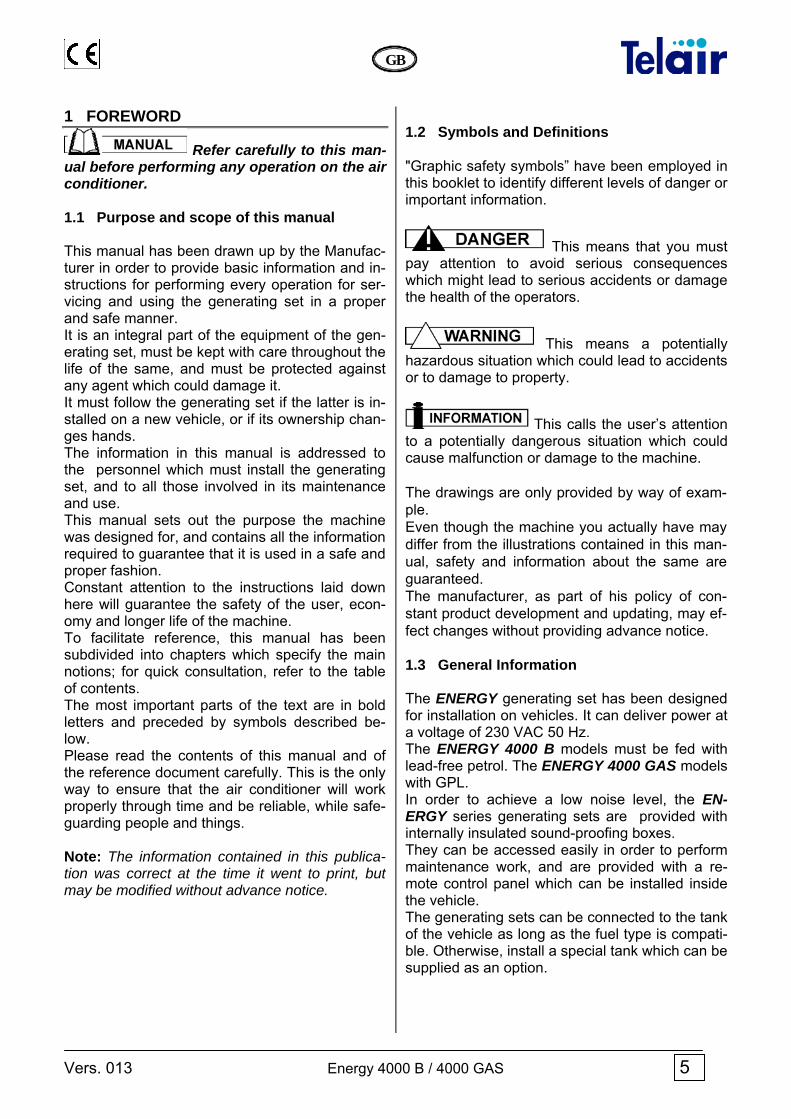
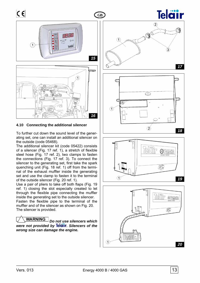
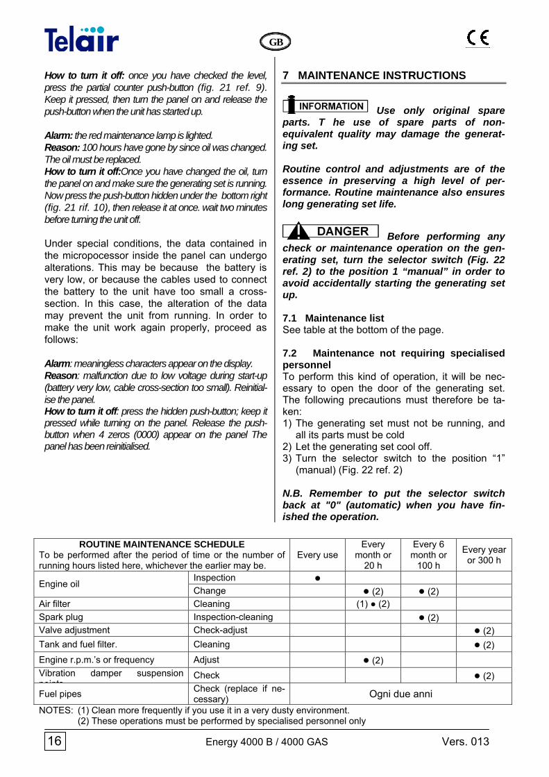
4.10 Connecting the additional silencer To further cut down the sound level of the gener-ating set, one can install an additional silencer on the outside (code 05468). The additional silencer kit (code 05422) consists of a silencer (Fig. 17 ref. 1), a stretch of flexible steel hose (Fig. 17 ref. 2), two clamps to fasten the connections (Fig. 17 ref. 3). To connect the silencer to the generating set, first take the spark quenching unit (Fig. 18 ref. 1) off from the termi-nal of the exhaust muffler inside the generating set and use the clamp to fasten it to the terminal of the outside silencer (Fig. 20 ref. 1). Use a pair of pliers to take off both flaps (Fig. 19 ref. 1) closing the slot especially created to let through the flexible pipe connecting the muffler inside the generating set to the outside silencer. Fasten the flexible pipe to the terminal of the muffler and of the silencer as shown on Fig. 20. The silencer is provided.
Do not use silencers which were not provided by . Silencers of the wrong size can damage the engine.
20
19
18
17
16
15

14 Energy 4000 B / 4000 GAS Vers. 013
GB
5 OPERATING INSTRUCTIONS ENERGY series generators are made from petrol or gas internal combustion engines connected to an alternator that can produce both alternating and direct electrical current. The generating sets are assembled inside a steel plate casing, insu-lated and sound-proofed using special sound ab-sorbing materials. The fuel is fed to the endothermic engine (only on petrol model) by a pump assembled standard on the generating set. 5.1 Machine safety The generating sets come with perfectly sealed casings, so there is no danger of contact with any mobile parts, with high temperatures or with live cables. The doors open with a lock and key. The keys must not be left within the reach of children or in-expert people.
The generating sets must be used only and exclusively with their doors shut. Remove any flammable substance from near the generating set, for example: petrol, paint, solvents, etc. Make sure the hot parts of the generating sets are not in touch with any easily flammable material. Never fill up the fuel tank while the generator is running. Never touch the generating sets or the wiring connections with wet hands. Never replace the fuses or the thermal swi-tches using others having a higher amperage. Should you have to check any electrical part, this must be done only with the engine turned off and by specialised personnel. The generating sets were made in compliance with the safety standards listed in the statement of compliance.
6 USING THE GENERATING SET 6.1 Starting up the generating set The generating sets are provided with a remote electronic control panel which allows you to per-form starting up / turning off operations and to check their running conditions. The elements making them up are: 1 ON/OFF switch 2 Display 3 High temperature indicator 4 Engine minimum oil level indicator 5 Startup failed 6 Generator running 7 Engine oil change indicator 8 Petrol reserve indicator 9 Display changeover switch 10 Reset Position the startup switch (Fig. 21 Ref. 1) on the “ON” position. The word “WAIT” will appear on the display for 8". When these have run out, the electronic control panel will start the first auto-matic procedure for starting up the generator set. If the engine starts up at the end of this phase, then “generator running” indicator (Fig. 21 ref. 6) will start to flash. Should the engine not start up, this automatic procedure will be repeated up to 4 times. If the engine has not started up yet at the end of this complete cycle, the “startup failed” indicator (Fig. 14 ref. 5) will light up to say that the generating set has failed to start up. If only the “startup failed” indicator (Fig. 21 ref. 5) stays lit, you can repeat the procedure several times. If the generating set has not started up at all e-ven after many attempts, you will have to get in touch with the After-sales service. Only on petrol model, should the battery have run out, you can start the generating sets by hand, using the handle of the engine coil winding (Fig. 22 ref. 1) after having set the selector switch in position “1” (Fig. 22 ref. 2) and the electronic con-trol panel in position “ON”. Once you have started the engine up manually, put the selector switch back in position “0” (Fig. 22 ref. 2). The start-up battery must never disconnected: in fact, the electronic control panel would no longer be fed, and this would prevent the generating sets from working.

Vers. 013 Energy 4000 B / 4000 GAS 15
GB
6.2 Turning the generating sets off To stop the generating set, place the “ON/OFF” switch in its OFF position (Fig. 21 ref. 1).
The generating set is provided with an internal combustion engine; therefore the fuel used is highly flammable. The exhaust gases are conveyed under the hood; their temperature, inevitably, is quite high, even though they are mixed with cool-ing air. Do not touch the hood areas near the ex-haust, and do not put your hands or other ob-jects inside the hood. 6.3 Information on forbidden use
The generating set must be installed and used only by personnel qua-lified and authorised according to the manu-facturer’s instructions. The generating set must be used only and exclusively to produce electrical power on vehicles provided with an electrical system made according to stan-dards and depending on the quantity of power delivered.
6.4 Suggestions To make the best use of the generating sets, re-member that even small overloads - if they last for some time - will make the temperature cut-off contact open (Fig. 22 ref. 3). During the running-in period, do not subject the new engine to a load higher than 70% of the ra-ted load, at least for the first 50 running hours. 6.5 Control and alarm functions (Fig. 21) 2 Display: when the generating set has started up, the total running hours will be displayed. Press the key (Fig. 21 ref. 9) to display the partial running hours of the generating set after the last change of the engine oil. 3 High temperature indicator: this warning light will light up when the temperature of the generat-ing set goes over its safety value; the engine will stop at the same time. 4 Engine oil minimum pressure indicator: this warning light will light up to indicate that the level of oil in the engine has gone below the minimum level. A safety system will turn the engine off au-tomatically in order to prevent breakages. 5 Engine startup failed: this warning light will light up to indicate that the generating set has not started up, after all four attempts at starting up have failed. 7 Change oil: this warning light will light up when the engine has reached 100 running hours after the last change of oil. Every time the oil is chan-ged, the After-sales service must reset the timer at zero. 8 Petrol reserve: this warning light will light up when the fuel level inside the extra tank has gone below its reserve level (about 4 litres) 9 Display changeover switch: press this to dis-play the running hours which have elapsed since the last time the engine oil was changed. 10 Reset: When the display shows any charac-ters without logic, the panel is to be reinitialised. Press the Reset key and, holding it down, switch on the panel. When 4 zeroes (0000) are shown on the display, the panel is reinitialised. 6.6 Initialising the GE penel and turning off alarms When you use the generator set, alarm signals may light up which refer to checking the oil of the unit. After having checked the oil, to put an end to the alarms proceed as follows: Alarm: the red maintenence lamp is flashing. Reason: 50 hours have gone by since oil was last chan-ged, and you must check its level.
21
22
16 Energy 4000 B / 4000 GAS Vers. 013
GB
How to turn it off: once you have checked the level, press the partial counter push-button (fig. 21 ref. 9). Keep it pressed, then turn the panel on and release the push-button when the unit has started up. Alarm: the red maintenance lamp is lighted. Reason: 100 hours have gone by since oil was changed. The oil must be replaced. How to turn it off:Once you have changed the oil, turn the panel on and make sure the generating set is running. Now press the push-button hidden under the bottom right (fig. 21 rif. 10), then release it at once. wait two minutes before turning the unit off. Under special conditions, the data contained in the micropocessor inside the panel can undergo alterations. This may be because the battery is very low, or because the cables used to connect the battery to the unit have too small a cross-section. In this case, the alteration of the data may prevent the unit from running. In order to make the unit work again properly, proceed as follows: Alarm: meaningless characters appear on the display. Reason: malfunction due to low voltage during start-up (battery very low, cable cross-section too small). Reinitial-ise the panel. How to turn it off: press the hidden push-button; keep it pressed while turning on the panel. Release the push-button when 4 zeros (0000) appear on the panel The panel has been reinitialised.
7 MAINTENANCE INSTRUCTIONS
Use only original spare parts. T he use of spare parts of non-equivalent quality may damage the generat-ing set. Routine control and adjustments are of the essence in preserving a high level of per-formance. Routine maintenance also ensures long generating set life.
Before performing any check or maintenance operation on the gen-erating set, turn the selector switch (Fig. 22 ref. 2) to the position 1 “manual” in order to avoid accidentally starting the generating set up. 7.1 Maintenance list See table at the bottom of the page.
7.2 Maintenance not requiring specialised personnel To perform this kind of operation, it will be nec-essary to open the door of the generating set. The following precautions must therefore be ta-ken: 1) The generating set must not be running, and
all its parts must be cold 2) Let the generating set cool off. 3) Turn the selector switch to the position “1”
(manual) (Fig. 22 ref. 2) N.B. Remember to put the selector switch back at "0" (automatic) when you have fin-ished the operation.
ROUTINE MAINTENANCE SCHEDULE To be performed after the period of time or the number of running hours listed here, whichever the earlier may be.
Every use Every
month or 20 h
Every 6 month or
100 h Every year or 300 h
Inspection ● Engine oil
Change ● (2) ● (2) Air filter Cleaning (1) ● (2) Spark plug Inspection-cleaning ● (2) Valve adjustment Check-adjust ● (2) Tank and fuel filter. Cleaning ● (2) Engine r.p.m.’s or frequency Adjust ● (2) Vibration damper suspension points
Check ● (2)
Fuel pipes Check (replace if ne-cessary) Ogni due anni
NOTES: (1) Clean more frequently if you use it in a very dusty environment. (2) These operations must be performed by specialised personnel only

Vers. 013 Energy 4000 B / 4000 GAS 17
GB
7.3 Checking the engine oil level • Unscrew the engine oil level reference cap
and clean the dipstick (Fig. 23 ref. 1). • Put the dipstick back in without screwing. • Take the dipstick out again, and make sure
that the engine oil level is between the two no-tches (min and max). Should the oil level be below the minimum notch, restore the level of the oil with the kind of motor oil advised (refer to the engine user and maintenance manual).
• Put the dipstick cap back on and screw tightly.
Do not exceed the maxi-mum level, since this could cause malfunc-tion of the fuel pump and hence of the gener-ating set.
Every engine oil level checking operation must be performed with the generating set in a perfectly horizontal position. 7.4 Maintenance operations calling for qualified personnel With certain maintenance operations, it is possi-ble to lower the engine-alternator unit, removing the hexagonal-headed screws (Fig. 24 ref. 1) and loosening the two studs (Fig. 24 ref. 2). This will make it easier to access all the inside parts of the generating set for unscheduled main-tenance or repair operations.
7.4.1 Engine oil replacement Use multigrade detergent oil for four-stroke petrol engines having a SAE viscosity suited to the cli-mate the generating set is working in (see table and detailed instructions shown on the engine use and maintenance manual). use and maintenance manual).
To make it easier to take the engine oil out, it is best to heat the engine for 3 - 5 minutes; this way, the oil will be more fluid and emptying will be quicker and more complete. Loosen the special cap on the oil pan by a few turns, and let all the oil inside run out into a col-lection container (Fig. 25 ref. 1).
When this has been done, screw the cap back on again and restore the oil level inside the engine pan, using the filler hole (Fig. 23 ref. 2). For the quantity of oil to be fed into the pan, see the following table (Table 2).
MOD. Quantity of oil (litres)
Energy 4000 B / 4000 GAS 1,0 Tab. 2
• Hot oil can scald. • Running the engine when the oil level is
too low can damage it seriously • Check the oil level when the engine has
been turned off.
Used oil must not be dis-posed of in the open, but handed over to companies specialising in disposal and/or re-cycling according to the laws current in the
24
23
25
For cold climates
For hot climates

18 Energy 4000 B / 4000 GAS Vers. 013
GB
country where such operations are per-formed. 7.4.2 Air filter maintenance
A dirty air filter will reduce the air flow to the carburettor. To prevent carburettor malfunction, check the air filter regularly. If the engine is used in an espe-cially dusty environment, we suggest you check it every time before starting up.
Never use Diesel fuel or solvents with a low evaporation point for cleaning the air filter cartridge. Never run the engine without the air filter; the engine would wear down quickly due to dust in the air. To access the filter cartridge, remove the air filter closing lid (Fig. 24 ref. 3) after having unscrewed both screws which keep it attached to the air filter box. Take out the cartridge (Fig. 26 ref. 1) and wash it using a neutral detergent solution and rinse care-fully. Let the filter cartridge dry out completely, then dip it in clean motor oil. Squeeze out care-fully in order to remove excess oil. Replace the cartridge only if it should be visibly no longer whole.
7.4.3 Spark plug maintenance For both models of generating sets, use spark plugs mod. BP6ES, BPR6ES (NGK), W20EP-U, W20EPR-U (ND) or else spark plugs made by other manufacturers but compatible with the abo-ve. Never use spark plugs with a different tempera-ture degree from those listed above.
• Take the cap off the spark plug (Fig. 26 ref. 2) and using the special wrench take out the plug.
• Perform a sight check. Replace in case of ob-
vious war or if the insulator is broken or cracked.
• Use a steel brush to clean the spark plug, if it can be used again.
• Use a thickness gauge to measure the dis-tance between the electrodes. The right dis-tance should be between 0.7 and 0.8 mm (Fig. 27).
• Correct the distance if necessary, folding the
side electrode. • Make sure that the spark plug washer is in
good condition and then screw back on by hand so as to be sure it is put back in place properly. Finally, tighten using the special wrench at the right torque (see instructions on the engine user and maintenance manual).
When assembling a new spark plug, tighten by 1/2 turn after the spark plug has compressed the sealing washer. If you put back the old plug after having re-moved it, tighten it by 1/4 turn after it has compressed the sealing washer.
The spark plug must be tightened firmly. A badly positioned spark plug may become very hot and damage the engine.
26
27

Vers. 013 Energy 4000 B / 4000 GAS 19
GB
7.4.4 Voltage adjustment Adjust the voltage when the engine is hot, no lo-ad is present and the generating set is running. Check the voltage of the generating set using a voltmeter via a 230 V vehicle socket. The voltage must be between 230 V and 245 V without any user being attached. If the values are different from this it will be nec-essary to set the right ones by working on the engine rev adjustment screw (Fig. 28 ref. 1). Turn the screw clockwise to increase the engine revs and hence the voltage. Turn the screw counter-clockwise to diminish the engine revs and hence the voltage.
8 INSTRUCTIONS ON PUTTING OUT OF WORK AND DISMANTLING 8.1 Long downtime
When the generator remains idle for at least three weeks, old unleaded petrol sediments could collect inside the carburettor. These sediments can seriously damage the en-gine and it is therefore COMPULSORY that the carburettor be completely emptied prior to a long period of non-use: do this by closing the fuel tap and running the generator set until it stops. It is also essential that you never use old unlea-ded petrol, as it can undergo chemical modifica-tions and seriously damage the engine. Failure to observe these instructions automati-cally renders the WARRANTY NULL AND VOID.
8.2 Dismantling Should you have to dismantle the generating set, refer to specialised shops.
9 FIRE-PREVENTION In case of fire, never open the hood of the gener-ating set and use only approved type fire extin-guishers.
Never use water to put out flames in the generating unit.
Electronic control panel connector
WHITE ORANGE GREY BLACK PURPLE RED BLUE WHITE GREEN BLUE YELLOW YELLOW ORANGE PINK RED GREY BROWN GREEN GENERATOR
28

20 Energy 4000 B / 4000 GAS Vers. 013
GB
WIRING DIAGRAM ENERGY 4000 B
Air
elec
trom
agne
t Fu
el re
serv
e M
otor
tem
pera
ture
ther
mos
tat
Low
oil
leve
l flo
at
Sta
rter b
atte
ry c
onne
ctio
n te
rmin
als
Sw
itch-
off r
elay
Ti
med
sw
itch-
off r
elay
B
atte
ry C
harg
er te
rmin
al
17
18
19
20
21
22
23
A
Con
dens
er
Pow
er c
onne
ctio
n te
rmin
al b
oard
Th
erm
al s
witc
h D
iode
brid
ge
"Man
ual/a
utom
atic
"sw
itch
Sta
rter
Pow
er-o
n co
ntro
l E
xter
nal f
uel p
ump
(opt
iona
l)
9 10
11
12
13
14
15
16
Ele
ctro
nic
cont
rol b
oard
C
ontro
l boa
rd c
onne
ctor
S
tarte
r eng
ine
rela
y O
N-O
FF R
elay
A
utom
atic
air
elec
trom
agne
t rel
ay
Rot
or
Alte
rnat
or
Sta
tor
1 2 3 4 5 6 7 8

Vers. 013 Energy 4000 B / 4000 GAS 21
GB
WIRING DIAGRAM ENERGY 4000 GAS
Pres
sure
redu
cer
GA
S s
olen
oid
valv
e Lo
w o
il le
vel f
loat
S
tarte
r bat
tery
con
nect
ion
term
inal
s M
otor
tem
pera
ture
ther
mos
tat
Tim
ed s
witc
h-of
f rel
ay
Mot
or te
mpe
ratu
re th
erm
osta
t B
atte
ry C
harg
er te
rmin
al
18
19
20
21
22
23
24
A
Pow
er c
onne
ctio
n te
rmin
al b
oard
Th
erm
al s
witc
h D
iode
brid
ge
Not
use
d S
tarte
r P
ower
-on
cont
rol
Fuse
E
xtra
GA
S b
utto
n
10
11
12
13
14
15
16
17
1Ele
ctro
nic
cont
rol b
oard
C
ontro
l boa
rd c
onne
ctor
S
tarte
r eng
ine
rela
y O
N-O
FF R
elay
N
ot u
sed
Rot
or
Alte
rnat
or
Sta
tor
Con
dens
er
1 2 3 4 5 6 7 8 9

22 Energy 4000 B / 4000 GAS Vers. 013
GB
DRAWING FOR SPARE PARTS LIST ENERGY 4000 B

Vers. 013 Energy 4000 B / 4000 GAS 23
GB
DRAWING FOR SPARE PARTS LIST ENERGY 4000 GAS

24 Energy 4000 B / 4000 GAS Vers. 013
GB
Pos. Code Q.tà Descrizione
Description
Dèsignation
Bezeichnung
Denomination
Descripcion
1 02015 N. 1 Cofano superiore Upper cowling
Capot supérieur Obere Haube
Bovenste kap Capo superior
2 00632 N. 4 Antivibrante Vib.damper ANTIOIL
Anti-vibr. 30x30 I 8MA FF SH 45 AN-TIHUILE
Schwing.bdämpf. 30x30 I 8MA FF SH 45 ÖLABW.
Trillingsdemp. 30x30 I 8MA FF SH 45 OLIEWEREND
Silenc. 30x30 I 8MA FF SH 45 AN-TIACEITE
3 01671 N. 2 Staffa ancoraggio Anchor clamp
Bride de fixation Befestigungsbügel
Verankeringsbeugel Estribo de anclaje
4 05505 N. 16
Rondella 6x18x1 UNI 6593 Washer 6x18x1 UNI 6593
Rondelle 6x18x1 UNI 6593 Scheibe 6x18x1 UNI 6593
Onderlegring 6x18x1 UNI 6593 Arandela 6x18x1 UNI 6593
5 02049 N. 1 Vite fissagio alternatore Alternator fastening screw
Vis de fixation de l’alternateur “Befestigungsschraube der Lichtma-
schine”
Bevestigingsschroef dynamo Tornillo sujecion alternador
6 01429 N. 1 FUSIONE 2501/A1 CASTING 2501/A1
MOULAGE 2501/A1 GUSSTEIL 2501/A1
GIETWERK 2501/A1 FUNDICION 2501/A1
7 01086 N. 4 Vite M6x160 UNI5931 Screw M6x160 UNI5931
Vis M6x160 UNI5931 Schraube M6x160 UNI5931
Schroef M6x160 UNI5931 Tornillo M6x160 UNI5931
8 02050 N. 1 Rondella alternatore Alternator washer
Rondelle de l’alternateur Scheibe der Lichtmaschine
Onderlegring dynamo Arandela alternador
9 02051 N. 1 Cuscinetto alternatore Alternator bearing
Palier de l’alternateur Lager der Lichtmaschine
Lager dynamo Cojinete alternador
10 02054 N. 2 Diodo alternatore Alternator diode
Diode de l’alternateur Diode der Lichtmaschine
Diode dynamo Diodo alternador
11 01989 N. 3 Antivibrante Vibration damper
Anti-vibrations Schwingungsdämpfer
Trillingsdemper Silenciador
12 02714 N. 1 Statore alternatore Alternator stator
Stator de l’alternateur Stator der Lichtmaschine
Stator dynamo Estator alternador
13 02054 N. 2 Diodo alternatore Alternator diode
Diode de l’alternateur Diode der Lichtmaschine
Diode dynamo Diodo alternador
14 02715 N. 1 Rotore alternatore Alternator rotor
Rotor de l’alternateur Rotor der Lichtmaschine
Rotor dynamo Rotor alternador
15 00299 N. 1 Motore EL. 12 V 0,30 kW El. Motor 12 V 0.30 kW
Moteur él. 12 V 0,30 kW Elektromotor 12 V 0,30 kW
El. motor 12 V 0,30 kW Motor el. 12 V 0,30 kW
16 03833 N. 1 Fusione ATR 4000/B1 Casting ATR 4000/B1
Moulage ATR 4000/B1 Gussteil ATR 4000/B1
Gietwerk ATR 4000/B1 Fundicion ATR 4000/B1
17 03727 N. 1 Corona dentata x mozzo flangiato Ring gear for flanged hub
Couronne dentée pour moyeu bridé Zahnkranz für Flanschnabe
Conisch tandwiel geflensde naaf Corona dentada cubo embridado
18 03829 N. 1 Ghiera Ring nut
Bague Nutmutter
Klemring Virola
19 03574 N. 1 Ventola Fan
Ventilateur Lufterrad
Ventilator Ventilador
20 02717 N. 1 Fusione ATR 4000/C1 Casting ATR 4000/C1
Moulage ATR 4000/C1 Gussteil ATR 4000/C1
Gietwerk ATR 4000/C1 Fundicion ATR 4000/C1
21 00958 N. 1 Pompa a depressione Vacuum pump
Pompè à dépression Vakuumpumpe
Vacuumpomp Bomba de vacio
22 01127 N. 4 Fascetta stringitubo Hose clamp
Collier serre-tube Schlauchschelle
Pijpklembandje Abrazadera para tubo
23 01442 0,7 m
Tubo Pipe
Tuyau Rohr
Pijp Tubo
24 02188 N. 1 Staffa supp. pompa carburante Fuel pump bearing bracket
Bride de support pompe à carburant Befestigungsbügel der Kraftstoffpumpe
Steunbeugel brandstofpomp Estribo soporte bomba carburante
25 02690 N. 1 Tappo filettato Threaded cap
Bouchon filetè Verschluss mit Gewinde
Schroefdraaddop Tapòn roscado
26 00478 N. 2 Raccordo 90° 1/8 MF Fitting 90° 1/8 MF
Raccord 90° 1/8 MF Anschlussstuck 90° 1/8 MF
Koppeling 90° 1/8 MF Empalme 90° 1/8 MF
27 01648 N. 1 Motore YAMAHA MZ 250 YAMAHA motor MZ 250
Moteur YAMAHA MZ 250 Motor YAMAHA MZ 250
YAMAHA motor MZ 250 Motor YAMAHA MZ 250
28 02729 N. 1 Filtro aria Air cleaner
Filtre à air Luftfilter
Luchtfilter Filtro aire
29 02619 N. 2 Supporto inferiore (optional) Lower support (optional)
Support inférieur (option) Unterer Halter (option)
Onderste steun (optie) Soporte inferior (opcional)
31 02743 N. 1 Candela Plug
Bougie Kerze
Bougie Bujia
32 00093 N. 1 Relè 12 V 70 A Relay 12 V 70 A
Relais 12 V 70 A Relais 12 V 70 A
Relais 12 V 70 A Rele 12 V 70 A
33 02014 N. 1 Basamento cassa Case base
Base de la caisse Kasten-Grundrahmen
Onderstel kast Base caja
34 00370 N. 3 Passacavo SKINTOP PG16 SKINTOP PG16 fairlead
Serre-câble SKINTOP PG16 Kabeldurchführung SKINTOP PG16
Kabeldoorvoer SKINTOP PG16 Pasacable SKINTOP PG16

Vers. 013 Energy 4000 B / 4000 GAS 25
GB
Pos. Code Q.tà Descrizione
Description
Dèsignation
Bezeichnung
Denomination
Descripcion
35 00369 N. 3 Dado plastica PG16 plastic nut
Ecrou plastique PG16 Kunststoffmutter PG16
Moer plastic PG16 Tuerca plástico PG16
36 00863 N. 2 Pressacavo SKINTOP PG9 SKINTOP cable gland
Serre-câble SKINTOP PG9 Kabelschelle SKINTOP PG9
Kabelklem SKINTOP PG9 Prensacable SKINTOP PG9
37 00854 N. 4 Vite UNI 5739 UNI 5739 screw
Vis UNI 5739 Schraube UNI 5739
Schroef UNI 5739 Tornillo UNI 5739
38 01251 N. 2 Diodo ponte raddrizzatore Bridge rectifier diode
Diode redresseur en pont Gleichrichterbrückendiode
Diode gelijkrichterbrug Diodo puente rectificador
39 01324 N. 1 Fascetta porta condensatore Condenser-holding clamp
Collier porte-condenseur Tragband fur Kondensator
Draagbandje condensator Abrazadera para condensador
40 01997 N. 1 Condensatore 18 μF Condenser 18 μF
Condensateur 18 μF Kondensator 18 μF
Condensator 18 μF Condensador 18 μF
41 02615 N. 1 Scatola marmitta Muffler box
Boitier du pot d'échappement Schalldampfergehause
Knaldemperkast Caja silenciador
42 00578 N. 4 Vite M 8x16 UNI 5739 Screw M 8x16 UNI 5739
Vis M 8x16 UNI 5739 Schraube M 8x16 UNI 5739
Schroef M 8x16 UNI 5739 Tornillo M 8x16 UNI5739
43 02186 N. 1 Collare scatola marmitta Muffler box collar
Collier boitier du pot d'échappement Bundring fur Schalldampfergehause
Kraagring knaldemperkast Collar caja silenciador
44 02408 N. 1 Marmitta Muffler
Pot d’échappement Auspufftopf
Knaldemper Silenciador de escape
45 02630 N. 1 Chiusura convogliatore Conveyor closure
Fermeture du convoyeur Verschluss Luftleitblech
Afdekking geleider Cierre transportador
46 02183 N. 1 Convogliatore alternatore Alternator conveyor
Convoyeur alternateur Luftleitblech Lichtmaschine
Geleider wisselstroomdynamo Transportador alternador
47 02185 N. 1 Chiusura scatola marmitta Muffler box closure
Fermeture du boitier du pot d'èchap-pement
Verschluss Schalldampfergehause
Afdekking knaldemperkast Cierre caja silenciador
48 00810 N. 1 Tappo Cap
Bouchon Kappe
Dop Tapon
49 01407 N. 1 Interruttore Manuale/Autom. Manual/Automatic Switch
Interrupteur Manuel/Automatique Schalter Hand/Auto
Schakelaar handb./autom. Interruptor Manual/Autom.
50 01838 N. 1 Scatola di comando Control box
Boîtier de commande Schaltkasten
Besturingskast Caja de mando
51 01209 N. 2 Morsetto LEGRAND 2x10 Clamp LEGRAND 2x10
Borne LEGRAND 2x10 Klemme LEGRAND 2x10
Aansluitklem LEGRAND 2x10 Borne LEGRAND 2x10
52 01139 N. 2 Morsetto Terminal
Borne Klemme
Aansluitklem Mordaza
53 01120 N. 1 Raccordo D10 GPL ottone Brass union D10 GPL
Raccord D10 GPL en cuivre Anschluss D10 GPL aus Messing
Messing LPG-koppeling D10 Union D10 GPL laton
54 01929 N. 1 Protezione termica Thermal protection
Protection thermique Wärmeschutz
Thermische beveiliging Protección térmica
55 01839 N. 1 Fondo scatola di comando Control box bottom
Fond du boîtier de commande Schaltkastenboden
Onderkant besturingskast Fondo caja de mando
56 02013 N. 1 Distanziatore ottone Brass spacer
Entretoise en cuivre Distanzstück aus Messung
Messing afstandshouder Riostra laton
57 01144 N. 1 Circuito stampato C.S. T0101 REV. CPrinted circuit T0101 C version
Circuit imprimé T0101 version C Gedruckte Schaltung T0101 Version C
Gedrukte schakeling T0101 versie CCircuito Impreso T0101 version
58 02187 N. 1 Staffa supporto choke Choke bearing bracket
Bride de support bobine Choke-Befestigungsbügel
Steunbeugel choke Estribo soporte bobina
59 00242 N. 1 Bobina Choke
Bobine Spule
Bobine Bobina
60 02072 N. 1 Boccola magnete Magnet bush
Bague aimant Magnet-Buchse
Magneetbus Casquillo iman
61 00704 N. 1 Molla Spring
Ressort Feder
Veer Resorte
62 02073 N. 1 Ancoretta magnete Magnet armature
Magnetanker Armature de l’aimant
Magneetanker Ancla iman
63 03648 N. 1 Molla comando choke Choke pushing spring
Ressort de commande bobine Choke-Betätigungsfeder
Bedieningsveer choke Resorte accionamiento bobina
64 02016 N. 1 Lamiera di chiusura sportello Door closing plate
Tôle de fermeture de porte Türblech
Afdekplaat deurtje Chapa cierre puerta
65 00642 N. 5 Vite M 6x16 UNI 5739 Screw M 6x16 UNI 5739
Vis M 6x16 UNI 5739 Schraube M 6x16 UNI 5739
Schroef M 6x16 UNI 5739 Tornillo M 6x16 UNI 5739
66 01224 N. 1 Serratura Lock
Serrure Schloss
Slot Cerradura
67 02697 N. 1 Cablaggio Harness
Câblage Verkabelung
Bedrading Cableado
68 01128 N. 1 Termostato 90° Thermostat 90°
Thermostat 90° Thermostat 90°
Thermostaat 90° Termostato 90°

26 Energy 4000 B / 4000 GAS Vers. 013
GB
Pos. Code Q.tà Descrizione
Description
Dèsignation
Bezeichnung
Denomination
Descripcion
69 03789 N. 4 Pannello di controllo ENERGY ENERGY control panel
Tableau/contrôle ENERGY Bedienpanel ENERGY
Schakelpaneel ENERGY Panel de control ENERGY
70 03830 N. 1 Cavo raccordo 5 m Jn cable 5 m
Câble raccord 5 m Verbindungskabel 5 m
Verbindingskabel 5 m Cable de empalme 5 m
71 01772 N. 1 Vite ISO 7380 ISO 7380 screw
Vis ISO 7380 Schraube ISO 7380
Schroef ISO 7380 Tornillo ISO 7380
72 02046 N. 2 Gommino protezione ponte di Diodi Diode bridge protection grommet
Protection en caoutchouc du pont de diodes
Gummiteil zum Schutz der Diodenbrü-cke
Beschermrubbertje gelijkrichterbrug Proteccion de caucho puente de
diodos
73 02732 N. 1 Tappo olio Oil cap
Bouchon de l’huile Ölschraube
Oliedop Tapon aceite
74 01251 N. 2 Diodo ponte raddrizzatore Bridge rectifier diode
Diode redresseur en pont Gleichrichterbrückendiode
Diode gelijkrichterbrug Diodo puente rectificador
75 02712 N. 1 Kit coibentazione Insulation kit
Kit de calorifugeage Isolierset
Isolatieset Kit Aislamiento termico
76 00931 N. 2 Rondella in alluminio Aluminium washer
Rondelle en aluminium Alu-Scheibe
Onderlegring van aluminium Arandela aluminio
78 01132 N. 1 Resca Union for vacuum pipe
Raccord pour tuyau à dépression Schlauchanschluss
Koppeling voor vacuümpijp Union para tubo depresion bomba
gasolina
80 02701 N. 1 Scatola filtro aria Air filter box
Boitier du filtre à air Luftfiltergehause
Behuizing luchtfilter Cajà filtro aire
81 00401 N. 2 Distanziatore acciaio Steel spacer
Entretoise en acier Distanzstück aus Stahl
Stalen afstandshouder Riostra acero
82 01388 N. 1 Passacavo Fairlead
Serre-câble Kabeldurchführung
Kabeldoorvoer Pasacable
83 02184 N. 1 Staffa fissaggio motore Engine fastening bracket
Bride de fixation du moteur Motor-Befestigungsbugel
Bevestigingsbeugel motor Abrazadera sujeciòn motor
84 02614 N. 1 Distanziale ventola Fan spacer
Entretoise du ventilateur Distanzstuck Lufter
Afstandshouder ventilator Riostra ventilador
85 03573 N. 1 Ventola 160 Fan 160
Ventilateur 160 Lufterrad 160
Ventilator 160 Ventilador 160
86 02468 N. 1 Minirelè temporizzato Timed minirelay
Mini-relais temporisè Zeitgeschaltetes minirelais
Minirelè tijdgeschakeld Minirelè temporizado
87 02189 N. 4 Staffe fissaggio cofano Hood fastening brackets
Bride de fixation de l'habillage Befestigungsbugel fur motorhaube
Bevestigingsbeugels kap Abrazaderas sujeciòn capò
88 02720 N. 1 Distanziale di supporto Support spacer
Entretoise de support Distanzstuck halter
Afstandshouder steun Riostra soporte
90 02727 N. 1 Scatola filtro aria Air filter box
Boitier du filtre à air Luftfiltergehause
Behuizing luchtfilter Cajà filtro aire
91 02728 N. 1 Supporto filtro aria Air filter support
Support du filtre à air Luftfilteraufnahme
Steun luchtfilter Soporte filtro aire
92 02730 N. 1 Coperchio filtro aria Air filter lid
Couvercle du filtre à air Luftfilterdeckel
Kap luchfilter Tapa filtro aire
93 03831 N. 1 Cavo raccordo 7 m Jn cable 7 m
Câble raccord 7 m Verbindungskabel 7 m
Verbindingskabel 7 m Cable de empalme 7 m
94 01349 N. 1 Riduttore di pressione Pressure reducer
Manodétendeur Druckreduzierer
Drukregelaar Reductor de presion
95 02292 N. 1 Bobina di starter Starter coil
Bobine d'allumage Starterspule
Starterspoel Bobina de starter
96 01344 N. 1 Bobina 12 Vcc Choke 12 Vcc
Bobine 12 Vcc Spule 12 Vcc
Bobine 12 Vcc Bobina 12 Vcc
97 01343 N. 1 Cablaggio esterno gas Gas external harness
Câblage extérieur du gaz Externe Verkabelung Gas
Externe gasbedrading Cableado exterior gas
98 03832 Cavo raccordo 15 m Jn cable 15 m
Câble raccord 15 m Verbindungskabel 15 m
Verbindingskabel 15 m Cable de empalme 15 m

Vers. 013 Energy 4000 B / 4000 GAS 27
GB
GENERAL INFORMATION FOR ENERGY 4000 GAS ONLY
CAUTION IMPORTANT
• Set the solenoid valves in vertical position. • Keep the air filter clean.
1 Cable n° 1, brown color, connected to the POSITIVE pole of the battery and to a terminal of the primer push button.
2 Cable n° 2, brown colour, connected to the POSITIVE pole of the battery and to the positive termi-
nal of the gas solenoide valve. 3 Cable n° 3, blue colour, connected to the terminal of the primer push button and to the positive
terminal of the primer solenoid valve. 4 Cable n° 4, yellow-green colour, connected to the negative terminals of two solenoid valves and
connected to another yellow-green cable inside the generator. 5 Primer solenoid valve. 6 Primer push button. 7 Gas solenoid valve. 8 Generator. 9 FUSE TO BE FITTED – 5 A (by the customer).

28 Energy 4000 B / 4000 GAS Vers. 013
GB
WIRING DIAGRAM INSIDE THE GENERATOR FOR THE CABLES OF THE LPG SYSTEM
FOR ENERGY 4000 B ONLY
1 Brown cable from the positive terminal of the battery to any of the terminals of the primer push but-
ton. 2 Brown cable from the positive terminal of the battery to the positive terminal of the gas solenoid
valve. 3 Yellow-green return cable of the external circuit of the gas system. 4 Yellow-green cable inside the generator, which the return cable is to be connected to. 5 Terminal which the positive terminal of the battery is to be connected.

Vers. 013 Energy 4000 B / 4000 GAS 29
GB
HOSE CONNECTION BETWEEN THE BOTTLE AND REDUCER FOR ENERGY 4000 GAS
Fig. A: The generator (1) is supplied by TELAIR complete with the special pres-sure reducer (2) and one metre long gas hose (3) to connect the pressure reducer to the generator.
The gas hose (4) to connect the pres-sure reducer to the gas bottle (5) is not supplied. Per questo collegamento l’installatore deve utilizzare un adeguato tubo omolo-gato munito degli adeguati raccordi.
Fig. A
IT IS FORBIDDEN to carry out connections to the pressure reducer and bottle as is shown in Fig. B.
The correct connecting procedure is shown in fig. C: the coupling (6) is gripped on a special hose. Insert the sleeve (7) and while holding the fixed hex nut (8) with a spanner tighten the ring nut (9).
Fig. B Fig. C

30 Energy 4000 B / 4000 GAS Vers. 013
GB
GENERAL WARRANTY TERMS TELAIR guarantees its products against any material and/or manufacturing faults and defects. The entitlement to warranty cover for new engines is valid for a period of 24 months from the time of handing over to the end user, or for a maxi-mum of 2000 operating hours, whichever of these limits is reached first. In all cases the warranty period shall lapse no later than 26 months (28 months if delivered outside Europe) after delivery ex factory. For electric and hydraulic components, pipes, belts, sealing elements, in-jection nozzles, clutches, gear boxes, the warranty term is 12 months from the time of handing over to the end user, or for a maximum of 2000 operat-ing hours, whichever of these limits is reached first. In all cases the war-ranty period shall lapse no later than 14 months (16 months if delivered outside Europe) after delivery ex factory. In any case, the costs of lubricants and consumables shall be charged. Any transport expenses shall be intended as to be covered by the purchaser; the same applies to any expenses connected with inspections requested by the customer and accepted by TELAIR. In any case, the costs of lubricants and consumables shall be charged. The manufacturer’s warranty shall only be valid if: • the customer has carried out any routine maintenance according to the rec-
ommended schedule and has promptly visited the nearest after-sale centre if required.
• the customer can produce a document showing the date of sale (invoice or receipt).
Such document will have to be kept with care and be intact when produced to the TELAIR After-Sales centre on requesting service.
In any case, the purchaser shall not be entitled to: • terminate the contract; • claim damages to persons or property; • ask that the warranty be extended in the event of product defects or malfunc-
tioning.

Vers. 013 Energy 4000 B / 4000 GAS 31
GB
Notes
……………………………………………………
……………………………………………………
……………………………………………………
……………………………………………………
……………………………………………………
……………………………………………………
……………………………………………………………………………………………………………
……………………………………………………………………………………………………………
……………………………………………………………………………………………………………
……………………………………………………………………………………………………………
……………………………………………………………………………………………………………
……………………………………………………………………………………………………………
……………………………………………………………………………………………………………
……………………………………………………………………………………………………………
……………………………………………………………………………………………………………
……………………………………………………………………………………………………………
……………………………………………………………………………………………………………
……………………………………………………………………………………………………………
……………………………………………………………………………………………………………
……………………………………………………………………………………………………………
……………………………………………………………………………………………………………
……………………………………………………………………………………………………………
……………………………………………………………………………………………………………
……………………………………………………………………………………………………………
……………………………………………………………………………………………………………

Foto e disegni non contrattuali - Les photos et les dessins ne sont donnés qu’à titre indicatif. We reserve the right to make technical changes without prior notice - Fotos und Zeichnungen nicht vertraglich. Fotos y planos no indicados en contrato
AIR CONDITIONER
IN EUROPE: GREAT BRITAIN - SCAN TERIEUR LTD 30, The Metro Centre, Tolpits Lane - Watford, Herts - England - WD18 9XG Tel. 01923 800353 - Fax 01923 220358 HOLLAND - KARMAN AGENTUREN Emmastraat, 31 1213 AJ Hilversum - Holland Tel. 035 6240156 - Fax 035 6242141 FRANCE - GERARD DURAND Lieu dit Borde Rouge 31590 Verfeil - France Tel. 05 61356238 - Fax. 05 61743502 [email protected] ESPAÑA - NAUCCA ACCESORIOS Y REPUESTOS Calle Pallars, 141 - 143 4°B 08018 Barcelona España Tel. 093 3099537 - Fax. 093 4850700 e-mail: [email protected] ÖSTERREICH - TELECO GmbH 82041 Deisenhofen - Tel. 08031 98939 - Fax. 08031 98949 e-mail: [email protected] www.telecogroup.com IN DEUTSCHLAND TELECO GmbH 82041 Deisenhofen - Tel. 08031 98939 - Fax. 08031 98949 Mit unserer Servicenummer sind Sie 01805 006 857 direkt mit dem Teleco-Vertreter in Ihrer Nähe verbunden.
KUNDENDIENST BEI AUSGEWÄHLTEN BOSCH SERVICE!
IN EUROPE: GREAT BRITAIN - SCAN TERIEUR LTD 30, The Metro Centre, Tolpits Lane - Watford, Herts - England - WD18 9XG Tel. 01923 800353 - Fax 01923 220358 HOLLAND / BELGIUM - KARMAN TRADING Lagewed 54 – 3849 PE Hierden – the Netherlands Tel. 0341 722450 - Fax 0341 722451 e-mail: [email protected] web site: www.karmantrading.nl FRANCE - BLEYS JEAN-PHILIPPE 19, Rue de la Parcheminerie 18700 Aubigny sur Nere - France Tel.02 48580367 – Fax 02 48583585 e-mail: [email protected] ESPAÑA - NAUCCA CARAVANING, S.A. Poligono Industrial CAN ROQUETA 2 – Calle Can Lletget,2 08202 Sabadell (Barcelona) - España Tel. 00 34 937 457 054 - Fax. 00 34 937 254 484 e-mail: [email protected] ÖSTERREICH – TELECO GmbH 82041 Deisenhofen - Deutshland Tel. 0049 8031 98939 - Fax. 0049 8031 98949 e-mail: [email protected] www.telecogroup.com
IN DEUTSHLAND TELECO GmbH 82041 Deisenhofen - Tel. 0049 8031 98939 - Fax. 0049 8031 98949 e-mail: [email protected] www.telecogroup.com
Händler und Info in Ihrer Nähe (Deutschland):
01805 006857
Service für Teleco Anlagen in Deutschland:
09001000045
ITALY Via E.Majorana 49 48022 LUGO( RA ) Tel. + 39 0545 25037 Fax.+ 39 0545 32064 E-mail: [email protected] www.telecogroup.com


![[013] ass 013 [1880]](https://img.pdfslide.us/doc/110x75/5695d38c1a28ab9b029e54d8/013-ass-013-1880.jpg)