Embed Size (px)
Citation preview
Video Security System
Endura™ Mapping
Operation
C3608M (9/07)

C3608M (9/07) 3
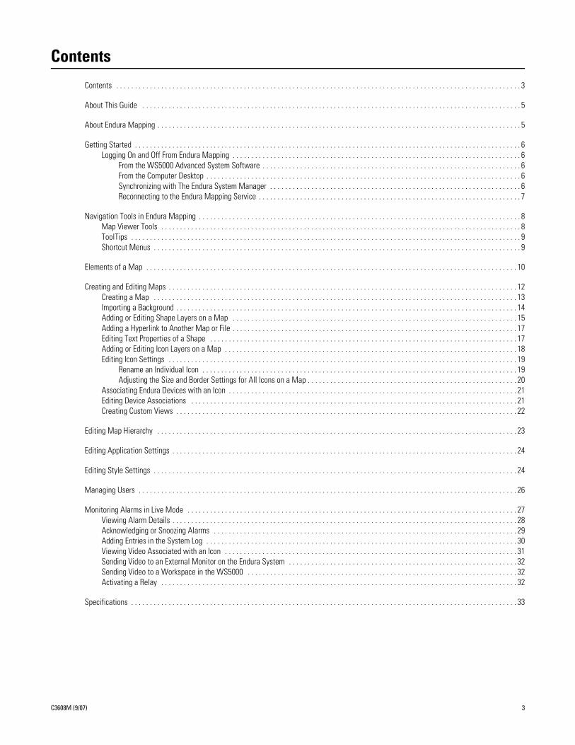
Contents
Contents . . . . . . . . . . . . . . . . . . . . . . . . . . . . . . . . . . . . . . . . . . . . . . . . . . . . . . . . . . . . . . . . . . . . . . . . . . . . . . . . . . . . . . . . . . . . . . . . . . . . . . . . . . . . 3
About This Guide . . . . . . . . . . . . . . . . . . . . . . . . . . . . . . . . . . . . . . . . . . . . . . . . . . . . . . . . . . . . . . . . . . . . . . . . . . . . . . . . . . . . . . . . . . . . . . . . . . . . . 5
About Endura Mapping . . . . . . . . . . . . . . . . . . . . . . . . . . . . . . . . . . . . . . . . . . . . . . . . . . . . . . . . . . . . . . . . . . . . . . . . . . . . . . . . . . . . . . . . . . . . . . . . . 5
Getting Started . . . . . . . . . . . . . . . . . . . . . . . . . . . . . . . . . . . . . . . . . . . . . . . . . . . . . . . . . . . . . . . . . . . . . . . . . . . . . . . . . . . . . . . . . . . . . . . . . . . . . . . 6Logging On and Off From Endura Mapping . . . . . . . . . . . . . . . . . . . . . . . . . . . . . . . . . . . . . . . . . . . . . . . . . . . . . . . . . . . . . . . . . . . . . . . . . . . . . 6
From the WS5000 Advanced System Software . . . . . . . . . . . . . . . . . . . . . . . . . . . . . . . . . . . . . . . . . . . . . . . . . . . . . . . . . . . . . . . . . . . . . 6From the Computer Desktop . . . . . . . . . . . . . . . . . . . . . . . . . . . . . . . . . . . . . . . . . . . . . . . . . . . . . . . . . . . . . . . . . . . . . . . . . . . . . . . . . . . . 6Synchronizing with The Endura System Manager . . . . . . . . . . . . . . . . . . . . . . . . . . . . . . . . . . . . . . . . . . . . . . . . . . . . . . . . . . . . . . . . . . . 6Reconnecting to the Endura Mapping Service . . . . . . . . . . . . . . . . . . . . . . . . . . . . . . . . . . . . . . . . . . . . . . . . . . . . . . . . . . . . . . . . . . . . . . 7
Navigation Tools in Endura Mapping . . . . . . . . . . . . . . . . . . . . . . . . . . . . . . . . . . . . . . . . . . . . . . . . . . . . . . . . . . . . . . . . . . . . . . . . . . . . . . . . . . . . . . 8Map Viewer Tools . . . . . . . . . . . . . . . . . . . . . . . . . . . . . . . . . . . . . . . . . . . . . . . . . . . . . . . . . . . . . . . . . . . . . . . . . . . . . . . . . . . . . . . . . . . . . . . . 8ToolTips . . . . . . . . . . . . . . . . . . . . . . . . . . . . . . . . . . . . . . . . . . . . . . . . . . . . . . . . . . . . . . . . . . . . . . . . . . . . . . . . . . . . . . . . . . . . . . . . . . . . . . . . 9Shortcut Menus . . . . . . . . . . . . . . . . . . . . . . . . . . . . . . . . . . . . . . . . . . . . . . . . . . . . . . . . . . . . . . . . . . . . . . . . . . . . . . . . . . . . . . . . . . . . . . . . . . 9
Elements of a Map . . . . . . . . . . . . . . . . . . . . . . . . . . . . . . . . . . . . . . . . . . . . . . . . . . . . . . . . . . . . . . . . . . . . . . . . . . . . . . . . . . . . . . . . . . . . . . . . . . . 10
Creating and Editing Maps . . . . . . . . . . . . . . . . . . . . . . . . . . . . . . . . . . . . . . . . . . . . . . . . . . . . . . . . . . . . . . . . . . . . . . . . . . . . . . . . . . . . . . . . . . . . . 12Creating a Map . . . . . . . . . . . . . . . . . . . . . . . . . . . . . . . . . . . . . . . . . . . . . . . . . . . . . . . . . . . . . . . . . . . . . . . . . . . . . . . . . . . . . . . . . . . . . . . . . 13Importing a Background . . . . . . . . . . . . . . . . . . . . . . . . . . . . . . . . . . . . . . . . . . . . . . . . . . . . . . . . . . . . . . . . . . . . . . . . . . . . . . . . . . . . . . . . . . . 14Adding or Editing Shape Layers on a Map . . . . . . . . . . . . . . . . . . . . . . . . . . . . . . . . . . . . . . . . . . . . . . . . . . . . . . . . . . . . . . . . . . . . . . . . . . . . 15Adding a Hyperlink to Another Map or File . . . . . . . . . . . . . . . . . . . . . . . . . . . . . . . . . . . . . . . . . . . . . . . . . . . . . . . . . . . . . . . . . . . . . . . . . . . . 17Editing Text Properties of a Shape . . . . . . . . . . . . . . . . . . . . . . . . . . . . . . . . . . . . . . . . . . . . . . . . . . . . . . . . . . . . . . . . . . . . . . . . . . . . . . . . . . 17Adding or Editing Icon Layers on a Map . . . . . . . . . . . . . . . . . . . . . . . . . . . . . . . . . . . . . . . . . . . . . . . . . . . . . . . . . . . . . . . . . . . . . . . . . . . . . . 18Editing Icon Settings . . . . . . . . . . . . . . . . . . . . . . . . . . . . . . . . . . . . . . . . . . . . . . . . . . . . . . . . . . . . . . . . . . . . . . . . . . . . . . . . . . . . . . . . . . . . . 19
Rename an Individual Icon . . . . . . . . . . . . . . . . . . . . . . . . . . . . . . . . . . . . . . . . . . . . . . . . . . . . . . . . . . . . . . . . . . . . . . . . . . . . . . . . . . . . 19Adjusting the Size and Border Settings for All Icons on a Map . . . . . . . . . . . . . . . . . . . . . . . . . . . . . . . . . . . . . . . . . . . . . . . . . . . . . . . . 20
Associating Endura Devices with an Icon . . . . . . . . . . . . . . . . . . . . . . . . . . . . . . . . . . . . . . . . . . . . . . . . . . . . . . . . . . . . . . . . . . . . . . . . . . . . . 21Editing Device Associations . . . . . . . . . . . . . . . . . . . . . . . . . . . . . . . . . . . . . . . . . . . . . . . . . . . . . . . . . . . . . . . . . . . . . . . . . . . . . . . . . . . . . . . 21Creating Custom Views . . . . . . . . . . . . . . . . . . . . . . . . . . . . . . . . . . . . . . . . . . . . . . . . . . . . . . . . . . . . . . . . . . . . . . . . . . . . . . . . . . . . . . . . . . . 22
Editing Map Hierarchy . . . . . . . . . . . . . . . . . . . . . . . . . . . . . . . . . . . . . . . . . . . . . . . . . . . . . . . . . . . . . . . . . . . . . . . . . . . . . . . . . . . . . . . . . . . . . . . . 23
Editing Application Settings . . . . . . . . . . . . . . . . . . . . . . . . . . . . . . . . . . . . . . . . . . . . . . . . . . . . . . . . . . . . . . . . . . . . . . . . . . . . . . . . . . . . . . . . . . . . 24
Editing Style Settings . . . . . . . . . . . . . . . . . . . . . . . . . . . . . . . . . . . . . . . . . . . . . . . . . . . . . . . . . . . . . . . . . . . . . . . . . . . . . . . . . . . . . . . . . . . . . . . . . 24
Managing Users . . . . . . . . . . . . . . . . . . . . . . . . . . . . . . . . . . . . . . . . . . . . . . . . . . . . . . . . . . . . . . . . . . . . . . . . . . . . . . . . . . . . . . . . . . . . . . . . . . . . . 26
Monitoring Alarms in Live Mode . . . . . . . . . . . . . . . . . . . . . . . . . . . . . . . . . . . . . . . . . . . . . . . . . . . . . . . . . . . . . . . . . . . . . . . . . . . . . . . . . . . . . . . . 27Viewing Alarm Details . . . . . . . . . . . . . . . . . . . . . . . . . . . . . . . . . . . . . . . . . . . . . . . . . . . . . . . . . . . . . . . . . . . . . . . . . . . . . . . . . . . . . . . . . . . . 28Acknowledging or Snoozing Alarms . . . . . . . . . . . . . . . . . . . . . . . . . . . . . . . . . . . . . . . . . . . . . . . . . . . . . . . . . . . . . . . . . . . . . . . . . . . . . . . . . 29Adding Entries in the System Log . . . . . . . . . . . . . . . . . . . . . . . . . . . . . . . . . . . . . . . . . . . . . . . . . . . . . . . . . . . . . . . . . . . . . . . . . . . . . . . . . . . 30Viewing Video Associated with an Icon . . . . . . . . . . . . . . . . . . . . . . . . . . . . . . . . . . . . . . . . . . . . . . . . . . . . . . . . . . . . . . . . . . . . . . . . . . . . . . 31Sending Video to an External Monitor on the Endura System . . . . . . . . . . . . . . . . . . . . . . . . . . . . . . . . . . . . . . . . . . . . . . . . . . . . . . . . . . . . . 32Sending Video to a Workspace in the WS5000 . . . . . . . . . . . . . . . . . . . . . . . . . . . . . . . . . . . . . . . . . . . . . . . . . . . . . . . . . . . . . . . . . . . . . . . . 32Activating a Relay . . . . . . . . . . . . . . . . . . . . . . . . . . . . . . . . . . . . . . . . . . . . . . . . . . . . . . . . . . . . . . . . . . . . . . . . . . . . . . . . . . . . . . . . . . . . . . . 32
Specifications . . . . . . . . . . . . . . . . . . . . . . . . . . . . . . . . . . . . . . . . . . . . . . . . . . . . . . . . . . . . . . . . . . . . . . . . . . . . . . . . . . . . . . . . . . . . . . . . . . . . . . . 33

About This GuideThank you for purchasing Pelco’s Endura™ Mapping application. This guide provides instructions on creating maps, editing application settings, and monitoring alarm events. For proper network configuration, follow the instructions in the Endura Network Design Guide, which is available at the Pelco Web site (www.pelco.com). For instructions on installing the application, refer to the Endura Mapping Quick Installation Guide. You also can find complete instructions for operating the application in the online help.
About Endura MappingEndura Mapping provides the following features and capabilities:
• Designs, manages, and displays maps of your site.
• Organizes maps into logical groups and links maps together for quick navigation and viewing.
• Imports images created in other drawing applications to serve as backgrounds.
• Imports AutoCAD® files that are saved as DXF files.
• Displays camera status and alarm events from icons that are strategically placed on the maps.
• Views video, responds to alarms, and activates relays through icon interaction.
• Integrates camera views with the WS5000 advanced system software.
• Communicates with the Endura system.
For best results when running Endura Mapping, this application should be installed on a computer or Endura Workstation to which two monitors are attached. Since Endura Mapping can be started directly from the WS5000, operators can view both applications simultaneously on the separate monitors. In such a working environment, Endura Mapping should be displayed on the secondary monitor.
Endura Mapping gives operators the ability to display the physical location of cameras, alarms, and other Endura devices throughout a facility. Careful integration with the Endura WS5000 Advanced System Software makes setting up a map fast and intuitive. A flexible user interface with powerful filtering and navigation tools makes working with maps an effective way of monitoring a large and geographically dispersed system for the operator.
The ability to use maps saved as AutoCAD® DXF files or in common graphics file formats allows administrators to quickly import an existing map to begin building a graphical representation of the site. Direct access to the Endura system means that administrators can assign cameras, alarms, relays, and other devices to map icons quickly and easily. Icons can be customized in size and color to manage clutter on a map while still providing an effective way of determining where key components are located. Hyperlinks can be inserted on a map to provide easy linking to other maps. Maps can be organized hierarchically into meaningful groups. Custom views of each map provide quick navigation through various map layers to drill down on alarm events at large sites. Custom shape layers, icon layers, and views serve the needs of various operators.
Operators can run Endura Mapping directly from the Endura WS5000 advanced system software. User rights and permissions are managed by the Endura SM5000 system manager, providing a single database for managing operator access to all Endura applications. Animated icons on maps indicate alarm severity as configured in Endura. The Map Browser automatically tallies the alarms as they occur in the system so that operators can quickly see the number, severity, and location of alarms from a single list. Operators can click an icon to access and acknowledge alarms, activate relays, view live video, and manage monitor wall displays without exiting Endura Mapping.
C3608M (9/07) 5
Getting Started
LOGGING ON AND OFF FROM ENDURA MAPPINGLog on to and off from Endura Mapping with one of the following methods.
FROM THE WS5000 ADVANCED SYSTEM SOFTWARE
1. From the WS5000 main screen, click the “Endura Mapping” button in the toolbar. The Endura Mapping main screen appears and displays the default map in Live Mode. If you have not selected a default map, follow the instructions in Editing Application Settings on page 24 to do so.
2. To close Endura Mapping, click the Close button in the upper right corner of the application window.
FROM THE COMPUTER DESKTOP
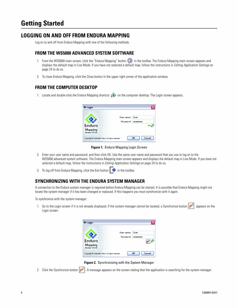
1. Locate and double-click the Endura Mapping shortcut on the computer desktop. The Login screen appears.
Figure 1. Endura Mapping Login Screen
2. Enter your user name and password, and then click OK. Use the same user name and password that you use to log on to the WS5000 advanced system software. The Endura Mapping main screen appears and displays the default map in Live Mode. If you have not selected a default map, follow the instructions in Editing Application Settings on page 24 to do so.
3. To log off from Endura Mapping, click the Exit button in the toolbar.
SYNCHRONIZING WITH THE ENDURA SYSTEM MANAGERA connection to the Endura system manager is required before Endura Mapping can be started. It is possible that Endura Mapping might not locate the system manager if it has been changed or replaced. If this happens you must synchronize with it again.
To synchronize with the system manager:
1. Go to the Login screen if it is not already displayed. If the system manager cannot be located, a Synchronize button appears on the Login screen.
Figure 2. Synchronizing with the System Manager
2. Click the Synchronize button . A message appears on the screen stating that the application is searching for the system manager.
6 C3608M (9/07)
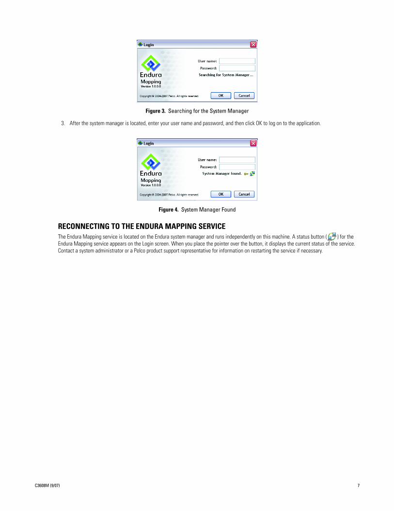
Figure 3. Searching for the System Manager
3. After the system manager is located, enter your user name and password, and then click OK to log on to the application.
Figure 4. System Manager Found
RECONNECTING TO THE ENDURA MAPPING SERVICEThe Endura Mapping service is located on the Endura system manager and runs independently on this machine. A status button ( ) for the Endura Mapping service appears on the Login screen. When you place the pointer over the button, it displays the current status of the service. Contact a system administrator or a Pelco product support representative for information on restarting the service if necessary.
C3608M (9/07) 7
Navigation Tools in Endura MappingEndura Mapping provides several features to navigate on a map. These features are available in both Live Mode and Edit Mode. The Tear-off feature is available while viewing a map in Live Mode.
MAP VIEWER TOOLS
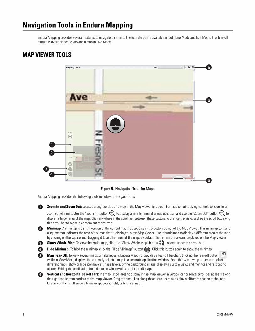
Figure 5. Navigation Tools for Maps
Endura Mapping provides the following tools to help you navigate maps.
Zoom In and Zoom Out: Located along the side of a map in the Map viewer is a scroll bar that contains sizing controls to zoom in or
zoom out of a map. Use the “Zoom In” button to display a smaller area of a map up close, and use the “Zoom Out” button to display a larger area of the map. Click anywhere in the scroll bar between these buttons to change the view, or drag the scroll box along this scroll bar to zoom in or zoom out of the map. Minimap: A minimap is a small version of the current map that appears in the bottom corner of the Map Viewer. This minimap contains a square that indicates the area of the map that is displayed in the Map Viewer. Use this minimap to display a different area of the map by clicking on the square and dragging it to another area of the map. By default the minimap is always displayed on the Map Viewer. Show Whole Map: To view the entire map, click the “Show Whole Map” button located under the scroll bar.
Hide Minimap: To hide the minimap, click the “Hide Minimap” button . Click this button again to show the minimap.
Map Tear-Off: To view several maps simultaneously, Endura Mapping provides a tear-off function. Clicking the Tear-off button while in View Mode displays the currently selected map in a separate application window. From this window operators can select different maps; show or hide icon layers, shape layers, or the background image; display a custom view; and monitor and respond to alarms. Exiting the application from the main window closes all tear-off maps.Vertical and horizontal scroll bars: If a map is too large to display in the Map Viewer, a vertical or horizontal scroll bar appears along the right and bottom borders of the Map Viewer. Drag the scroll box along these scroll bars to display a different section of the map. Use any of the scroll arrows to move up, down, right, or left in a map.
��
�
�
�
�
�
8 C3608M (9/07)
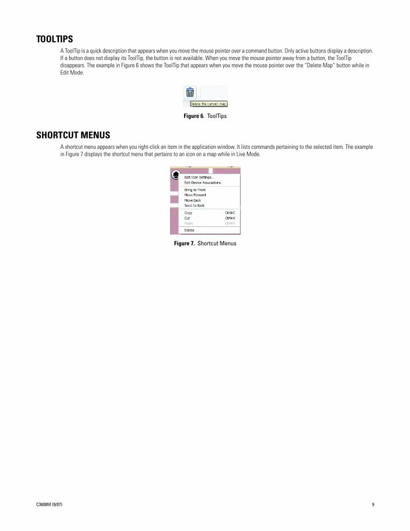
TOOLTIPSA ToolTip is a quick description that appears when you move the mouse pointer over a command button. Only active buttons display a description. If a button does not display its ToolTip, the button is not available. When you move the mouse pointer away from a button, the ToolTip disappears. The example in Figure 6 shows the ToolTip that appears when you move the mouse pointer over the “Delete Map” button while in Edit Mode.
Figure 6. ToolTips
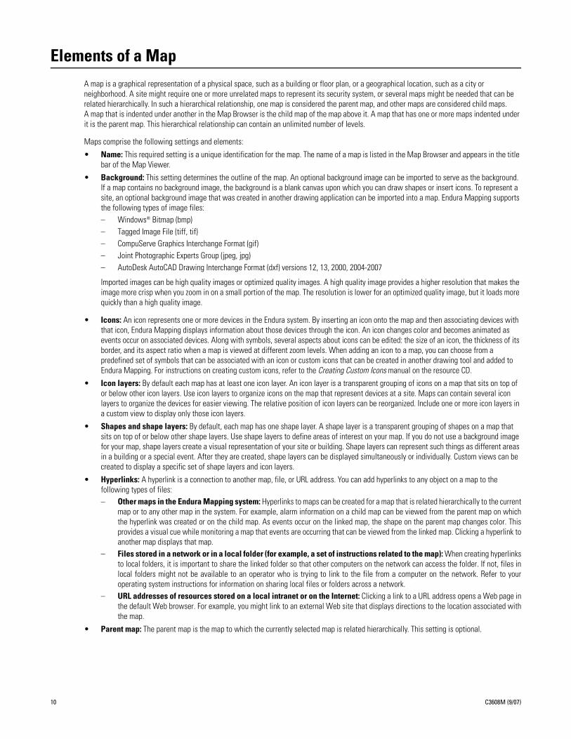
SHORTCUT MENUSA shortcut menu appears when you right-click an item in the application window. It lists commands pertaining to the selected item. The example in Figure 7 displays the shortcut menu that pertains to an icon on a map while in Live Mode.
Figure 7. Shortcut Menus
C3608M (9/07) 9
Elements of a MapA map is a graphical representation of a physical space, such as a building or floor plan, or a geographical location, such as a city or neighborhood. A site might require one or more unrelated maps to represent its security system, or several maps might be needed that can be related hierarchically. In such a hierarchical relationship, one map is considered the parent map, and other maps are considered child maps. A map that is indented under another in the Map Browser is the child map of the map above it. A map that has one or more maps indented under it is the parent map. This hierarchical relationship can contain an unlimited number of levels.
Maps comprise the following settings and elements:
• Name: This required setting is a unique identification for the map. The name of a map is listed in the Map Browser and appears in the title bar of the Map Viewer.
• Background: This setting determines the outline of the map. An optional background image can be imported to serve as the background. If a map contains no background image, the background is a blank canvas upon which you can draw shapes or insert icons. To represent a site, an optional background image that was created in another drawing application can be imported into a map. Endura Mapping supports the following types of image files: – Windows® Bitmap (bmp)– Tagged Image File (tiff, tif)– CompuServe Graphics Interchange Format (gif)– Joint Photographic Experts Group (jpeg, jpg)– AutoDesk AutoCAD Drawing Interchange Format (dxf) versions 12, 13, 2000, 2004-2007
Imported images can be high quality images or optimized quality images. A high quality image provides a higher resolution that makes the image more crisp when you zoom in on a small portion of the map. The resolution is lower for an optimized quality image, but it loads more quickly than a high quality image.
• Icons: An icon represents one or more devices in the Endura system. By inserting an icon onto the map and then associating devices with that icon, Endura Mapping displays information about those devices through the icon. An icon changes color and becomes animated as events occur on associated devices. Along with symbols, several aspects about icons can be edited: the size of an icon, the thickness of its border, and its aspect ratio when a map is viewed at different zoom levels. When adding an icon to a map, you can choose from a predefined set of symbols that can be associated with an icon or custom icons that can be created in another drawing tool and added to Endura Mapping. For instructions on creating custom icons, refer to the Creating Custom Icons manual on the resource CD.
• Icon layers: By default each map has at least one icon layer. An icon layer is a transparent grouping of icons on a map that sits on top of or below other icon layers. Use icon layers to organize icons on the map that represent devices at a site. Maps can contain several icon layers to organize the devices for easier viewing. The relative position of icon layers can be reorganized. Include one or more icon layers in a custom view to display only those icon layers.
• Shapes and shape layers: By default, each map has one shape layer. A shape layer is a transparent grouping of shapes on a map that sits on top of or below other shape layers. Use shape layers to define areas of interest on your map. If you do not use a background image for your map, shape layers create a visual representation of your site or building. Shape layers can represent such things as different areas in a building or a special event. After they are created, shape layers can be displayed simultaneously or individually. Custom views can be created to display a specific set of shape layers and icon layers.
• Hyperlinks: A hyperlink is a connection to another map, file, or URL address. You can add hyperlinks to any object on a map to the following types of files:– Other maps in the Endura Mapping system: Hyperlinks to maps can be created for a map that is related hierarchically to the current
map or to any other map in the system. For example, alarm information on a child map can be viewed from the parent map on whichthe hyperlink was created or on the child map. As events occur on the linked map, the shape on the parent map changes color. Thisprovides a visual cue while monitoring a map that events are occurring that can be viewed from the linked map. Clicking a hyperlink toanother map displays that map.
– Files stored in a network or in a local folder (for example, a set of instructions related to the map): When creating hyperlinksto local folders, it is important to share the linked folder so that other computers on the network can access the folder. If not, files inlocal folders might not be available to an operator who is trying to link to the file from a computer on the network. Refer to youroperating system instructions for information on sharing local files or folders across a network.
– URL addresses of resources stored on a local intranet or on the Internet: Clicking a link to a URL address opens a Web page inthe default Web browser. For example, you might link to an external Web site that displays directions to the location associated withthe map.
• Parent map: The parent map is the map to which the currently selected map is related hierarchically. This setting is optional.
10 C3608M (9/07)
• Scale: The scale of a map determines the ratio of the actual physical space that the map represents in relation to the map as it is viewed in Endura Mapping. Map scale is adjusted based on the unit of measurement (standard or metric) that is set for the map each time you zoom in or out of the map. When setting the scale of a map, the following optional settings are available:– System of measurement: Maps can be measured using either the standard system (miles, feet, inches, etc.), or the metric system
(kilometers, meters, centimeters, etc.).– Width and height: These settings determine the virtual dimensions of the map as viewed in Endura Mapping. Width and height can
be greater than the available screen size. When the width and height are greater than the screen size, vertical or horizontal scroll barsare provided in the Map Viewer. When the entire map is visible in the Map Viewer, the scroll bars are not available.
– Conversion chart: A conversion chart provides the relationship of a unit of measurement on the map to the physical space the maprepresents. For example, a mile might be represented on the map by a single inch or centimeter. If necessary, degrees on the globe canbe converted to smaller units of measure. When converting to degrees, only the width of the map can be scaled to degrees. Expressedas Latitude (Lat.°) on the conversion chart, one degree represents 69.2 miles (111.37 km).
– Physical location (latitude and longitude): The physical location of a map identifies the actual position of the upper-left corner ofthe map on the Earth. This location is determined by entering the latitude and longitude of the upper-left corner of the map.
C3608M (9/07) 11
Creating and Editing MapsTo create or edit maps, you must be logged on to Endura Mapping with a user ID that has permissions to edit maps. Permissions to any function in an Endura system are assigned from the WS5000.
Several tasks are involved in creating and editing maps from while in Edit Mode. Refer to the following sections for instructions on these tasks:
• Creating a Map on page 13.• Importing a Background on page 14.• Adding or Editing Shape Layers on a Map on page 15.• Adding a Hyperlink to Another Map or File on page 17.• Adding or Editing Icon Layers on a Map on page 18.• Associating Endura Devices with an Icon on page 21.• Editing Device Associations on page 21.• Creating Custom Views on page 22.
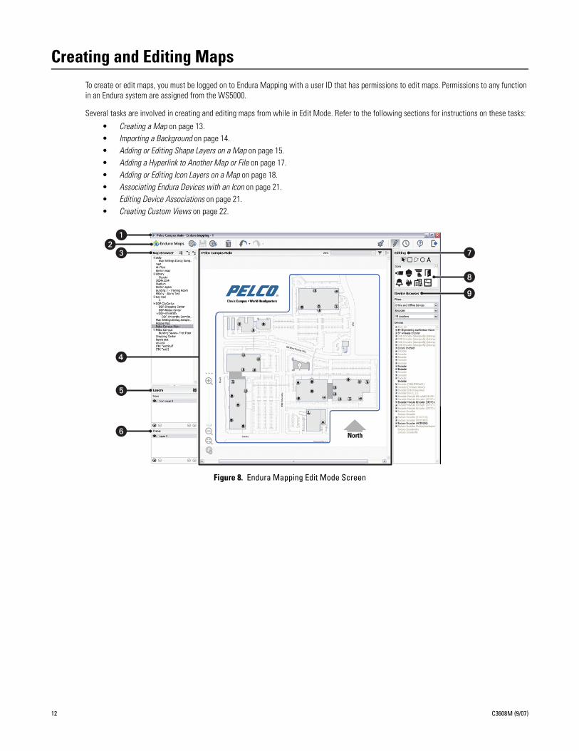
Figure 8. Endura Mapping Edit Mode Screen
12 C3608M (9/07)
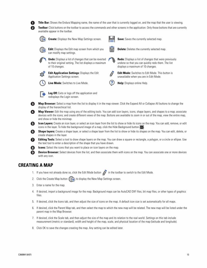
CREATING A MAP1. If you have not already done so, click the Edit Mode button in the toolbar to switch to the Edit Mode.
2. Click the Create Map button to display the New Map Settings screen.
3. Enter a name for the map.
4. If desired, import a background image for the map. Background maps can be AutoCAD DXF files, bit map files, or other types of graphics files.
5. If desired, click the Icons tab, and then adjust the size of icons on the map. A default icon size is set automatically for all maps.
6. If desired, click the Parent Map tab, and then select the map to which the new map will be related. The new map will be listed under the parent map in the Map Browser.
7. If desired, click the Scale tab, and then adjust the size of the map and its relation to the real world. Settings on this tab include measurement (metric or standard), width and height of the map, scale, and physical location of the map (latitude and longitude).
8. Click OK to save the changes creating the map. Any setting can be edited later.
Title Bar: Shows the Endura Mapping name, the name of the user that is currently logged on, and the map that the user is viewing.
Toolbar: Click buttons on the toolbar to access the commands and other screens in the application. Only those buttons that are currently available appear in the toolbar.
Create: Displays the New Map Settings screen. Save: Saves the currently selected map.
Edit: Displays the Edit map screen from which you can modify map settings.
Delete: Deletes the currently selected map.
Undo: Displays a list of changes that can be reverted to their original setting. The list displays a maximum of 10 changes.
Redo: Displays a list of changes that were previously undone so that you can quickly redo them. The list displays a maximum of 10 changes.
Edit Application Settings: Displays the Edit Application Settings screen.
Edit Mode: Switches to Edit Mode. This button is unavailable when you are in Edit Mode.
Live Mode: Switches to Live Mode. Help: Displays online Help.
Log Off: Exits or logs off the application and redisplays the Login screen.
Map Browser: Select a map from the list to display it in the map viewer. Click the Expand All or Collapse All buttons to change the display of the hierarchical list.Map Viewer: Edit the map using any of the editing tools. You can add icon layers, icons, shape layers, and shapes to a map; associate devices with the icons; and create different views of the map. Buttons are available to zoom in or out of the map, view the entire map, and show or hide the minimap.Icon Layers: Create an icon layer, or select an icon layer from the list to show or hide its icons on the map. You can add, remove, or edit icons in the layer. To hide the background image of a map, click the Hide Background button .Shape layers: Create a shape layer, or select a shape layer from the list to show or hide its shapes on the map. You can edit, delete, or create shapes in the layer. Editing Tools: Select a tool to draw shape layers on the map. You can draw a square or rectangle, a polygon, or a circle or ellipse. Use the text tool to enter a description of the shape that you have drawn.Icons: Select the icons that you want to place on icon layers on the map.
Device Browser: Select devices from the list, and then associate them with icons on the map. You can associate one or more devices with any icon.
C3608M (9/07) 13
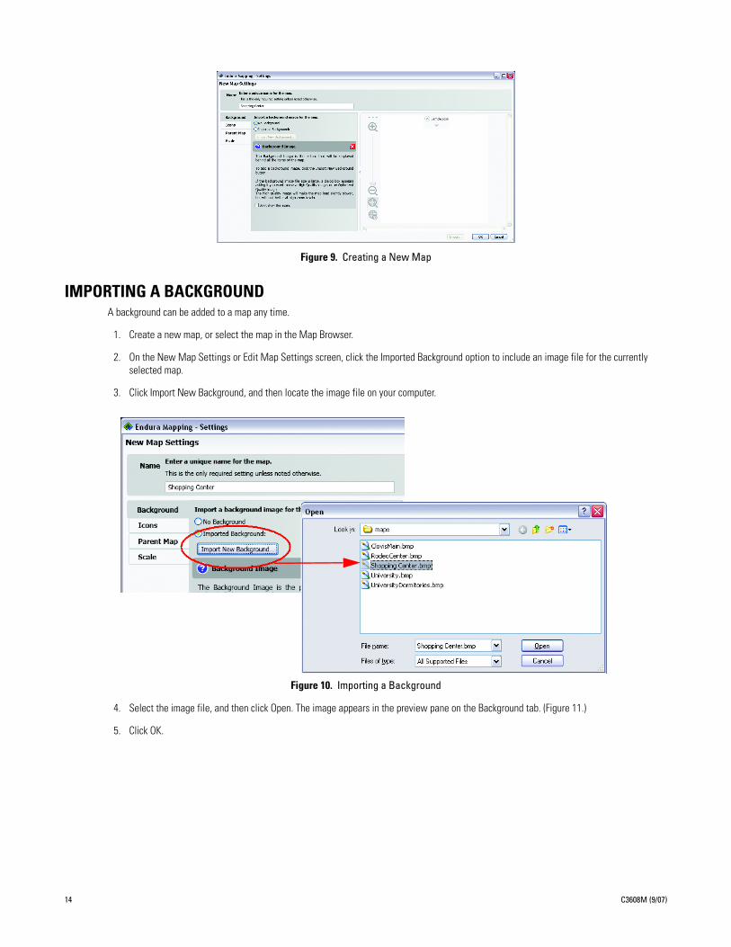
Figure 9. Creating a New Map
IMPORTING A BACKGROUNDA background can be added to a map any time.
1. Create a new map, or select the map in the Map Browser.
2. On the New Map Settings or Edit Map Settings screen, click the Imported Background option to include an image file for the currently selected map.
3. Click Import New Background, and then locate the image file on your computer.
Figure 10. Importing a Background
4. Select the image file, and then click Open. The image appears in the preview pane on the Background tab. (Figure 11.)
5. Click OK.
14 C3608M (9/07)
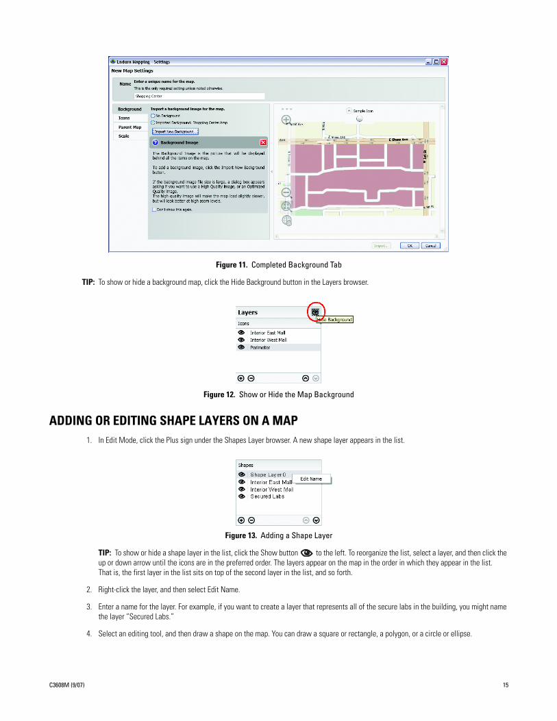
Figure 11. Completed Background Tab
TIP: To show or hide a background map, click the Hide Background button in the Layers browser.
Figure 12. Show or Hide the Map Background
ADDING OR EDITING SHAPE LAYERS ON A MAP1. In Edit Mode, click the Plus sign under the Shapes Layer browser. A new shape layer appears in the list.
Figure 13. Adding a Shape Layer
TIP: To show or hide a shape layer in the list, click the Show button to the left. To reorganize the list, select a layer, and then click the up or down arrow until the icons are in the preferred order. The layers appear on the map in the order in which they appear in the list. That is, the first layer in the list sits on top of the second layer in the list, and so forth.
2. Right-click the layer, and then select Edit Name.
3. Enter a name for the layer. For example, if you want to create a layer that represents all of the secure labs in the building, you might name the layer “Secured Labs.”
4. Select an editing tool, and then draw a shape on the map. You can draw a square or rectangle, a polygon, or a circle or ellipse.
C3608M (9/07) 15
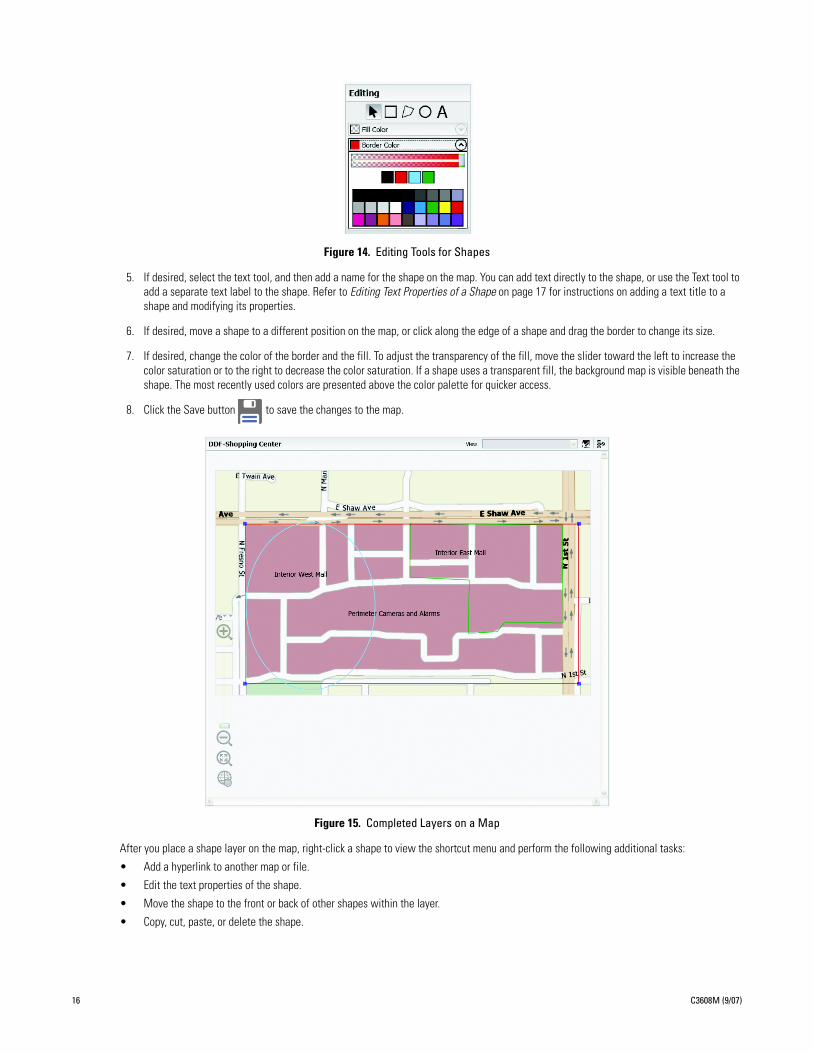
Figure 14. Editing Tools for Shapes
5. If desired, select the text tool, and then add a name for the shape on the map. You can add text directly to the shape, or use the Text tool to add a separate text label to the shape. Refer to Editing Text Properties of a Shape on page 17 for instructions on adding a text title to a shape and modifying its properties.
6. If desired, move a shape to a different position on the map, or click along the edge of a shape and drag the border to change its size.
7. If desired, change the color of the border and the fill. To adjust the transparency of the fill, move the slider toward the left to increase the color saturation or to the right to decrease the color saturation. If a shape uses a transparent fill, the background map is visible beneath the shape. The most recently used colors are presented above the color palette for quicker access.
8. Click the Save button to save the changes to the map.
Figure 15. Completed Layers on a Map
After you place a shape layer on the map, right-click a shape to view the shortcut menu and perform the following additional tasks:
• Add a hyperlink to another map or file.
• Edit the text properties of the shape.
• Move the shape to the front or back of other shapes within the layer.
• Copy, cut, paste, or delete the shape.
16 C3608M (9/07)
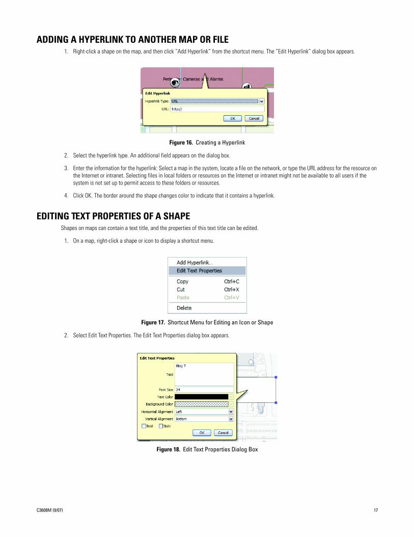
ADDING A HYPERLINK TO ANOTHER MAP OR FILE1. Right-click a shape on the map, and then click “Add Hyperlink” from the shortcut menu. The “Edit Hyperlink” dialog box appears.
Figure 16. Creating a Hyperlink
2. Select the hyperlink type. An additional field appears on the dialog box.
3. Enter the information for the hyperlink: Select a map in the system, locate a file on the network, or type the URL address for the resource on the Internet or intranet. Selecting files in local folders or resources on the Internet or intranet might not be available to all users if the system is not set up to permit access to these folders or resources.
4. Click OK. The border around the shape changes color to indicate that it contains a hyperlink.
EDITING TEXT PROPERTIES OF A SHAPEShapes on maps can contain a text title, and the properties of this text title can be edited.
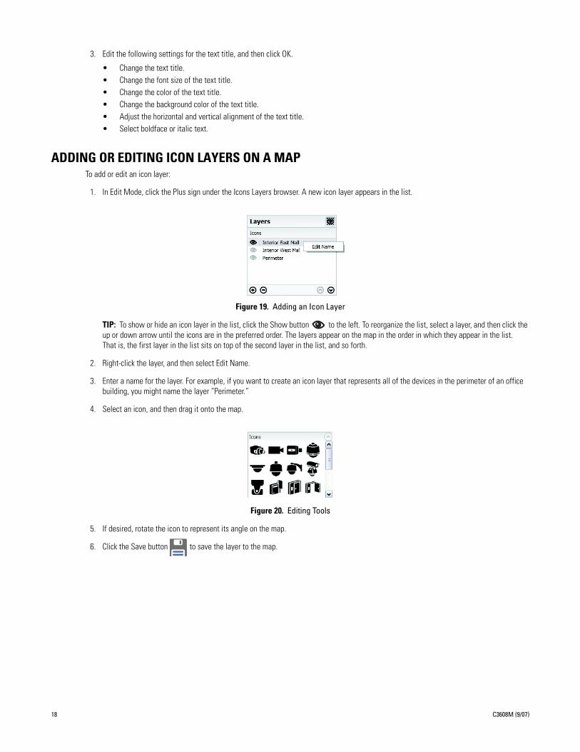
1. On a map, right-click a shape or icon to display a shortcut menu.
Figure 17. Shortcut Menu for Editing an Icon or Shape
2. Select Edit Text Properties. The Edit Text Properties dialog box appears.
Figure 18. Edit Text Properties Dialog Box
C3608M (9/07) 17
3. Edit the following settings for the text title, and then click OK.
• Change the text title.• Change the font size of the text title.• Change the color of the text title.• Change the background color of the text title.• Adjust the horizontal and vertical alignment of the text title.• Select boldface or italic text.
ADDING OR EDITING ICON LAYERS ON A MAPTo add or edit an icon layer:
1. In Edit Mode, click the Plus sign under the Icons Layers browser. A new icon layer appears in the list.
Figure 19. Adding an Icon Layer
TIP: To show or hide an icon layer in the list, click the Show button to the left. To reorganize the list, select a layer, and then click the up or down arrow until the icons are in the preferred order. The layers appear on the map in the order in which they appear in the list. That is, the first layer in the list sits on top of the second layer in the list, and so forth.
2. Right-click the layer, and then select Edit Name.
3. Enter a name for the layer. For example, if you want to create an icon layer that represents all of the devices in the perimeter of an office building, you might name the layer “Perimeter.”
4. Select an icon, and then drag it onto the map.
Figure 20. Editing Tools
5. If desired, rotate the icon to represent its angle on the map.
6. Click the Save button to save the layer to the map.
18 C3608M (9/07)

Figure 21. Completed Icons on a Map
EDITING ICON SETTINGS
RENAME AN INDIVIDUAL ICONTo perform these tasks, select Edit Icon Settings from the shortcut menu.
Figure 22. Edit Icon Settings Screen
C3608M (9/07) 19
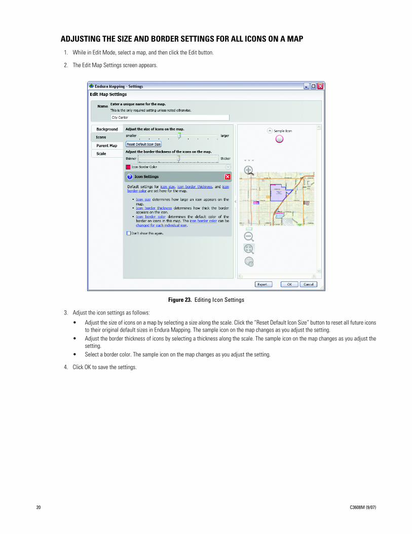
ADJUSTING THE SIZE AND BORDER SETTINGS FOR ALL ICONS ON A MAP
1. While in Edit Mode, select a map, and then click the Edit button.
2. The Edit Map Settings screen appears.
Figure 23. Editing Icon Settings
3. Adjust the icon settings as follows:
• Adjust the size of icons on a map by selecting a size along the scale. Click the “Reset Default Icon Size” button to reset all future iconsto their original default sizes in Endura Mapping. The sample icon on the map changes as you adjust the setting.
• Adjust the border thickness of icons by selecting a thickness along the scale. The sample icon on the map changes as you adjust thesetting.
• Select a border color. The sample icon on the map changes as you adjust the setting.
4. Click OK to save the settings.
20 C3608M (9/07)
ASSOCIATING ENDURA DEVICES WITH AN ICON1. From the Edit Mode screen, display the desired icon layer on the map.
2. In the Device Browser list, use the filters to sort the list. You can display devices by their availability (online or offline), by type (camera, encoder, alarm, and so forth), or by location.
3. Select a device or group of devices, and then drag it to the icon. A message appears confirming that the devices have been associated with the icon.
Figure 24. New Device Association Message
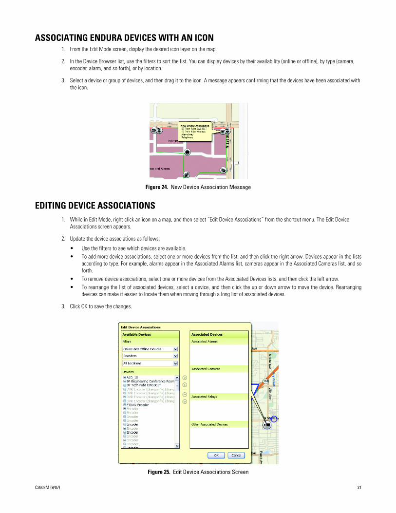
EDITING DEVICE ASSOCIATIONS1. While in Edit Mode, right-click an icon on a map, and then select “Edit Device Associations” from the shortcut menu. The Edit Device
Associations screen appears.
2. Update the device associations as follows:
• Use the filters to see which devices are available.• To add more device associations, select one or more devices from the list, and then click the right arrow. Devices appear in the lists
according to type. For example, alarms appear in the Associated Alarms list, cameras appear in the Associated Cameras list, and soforth.
• To remove device associations, select one or more devices from the Associated Devices lists, and then click the left arrow.• To rearrange the list of associated devices, select a device, and then click the up or down arrow to move the device. Rearranging
devices can make it easier to locate them when moving through a long list of associated devices.
3. Click OK to save the changes.
Figure 25. Edit Device Associations Screen
C3608M (9/07) 21
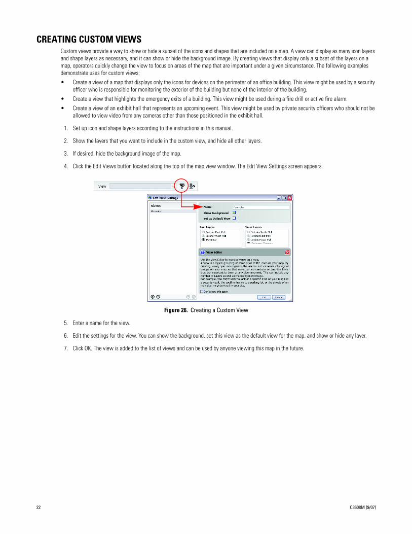
CREATING CUSTOM VIEWSCustom views provide a way to show or hide a subset of the icons and shapes that are included on a map. A view can display as many icon layers and shape layers as necessary, and it can show or hide the background image. By creating views that display only a subset of the layers on a map, operators quickly change the view to focus on areas of the map that are important under a given circumstance. The following examples demonstrate uses for custom views:
• Create a view of a map that displays only the icons for devices on the perimeter of an office building. This view might be used by a security officer who is responsible for monitoring the exterior of the building but none of the interior of the building.
• Create a view that highlights the emergency exits of a building. This view might be used during a fire drill or active fire alarm.
• Create a view of an exhibit hall that represents an upcoming event. This view might be used by private security officers who should not be allowed to view video from any cameras other than those positioned in the exhibit hall.
1. Set up icon and shape layers according to the instructions in this manual.
2. Show the layers that you want to include in the custom view, and hide all other layers.
3. If desired, hide the background image of the map.
4. Click the Edit Views button located along the top of the map view window. The Edit View Settings screen appears.
Figure 26. Creating a Custom View
5. Enter a name for the view.
6. Edit the settings for the view. You can show the background, set this view as the default view for the map, and show or hide any layer.
7. Click OK. The view is added to the list of views and can be used by anyone viewing this map in the future.
22 C3608M (9/07)
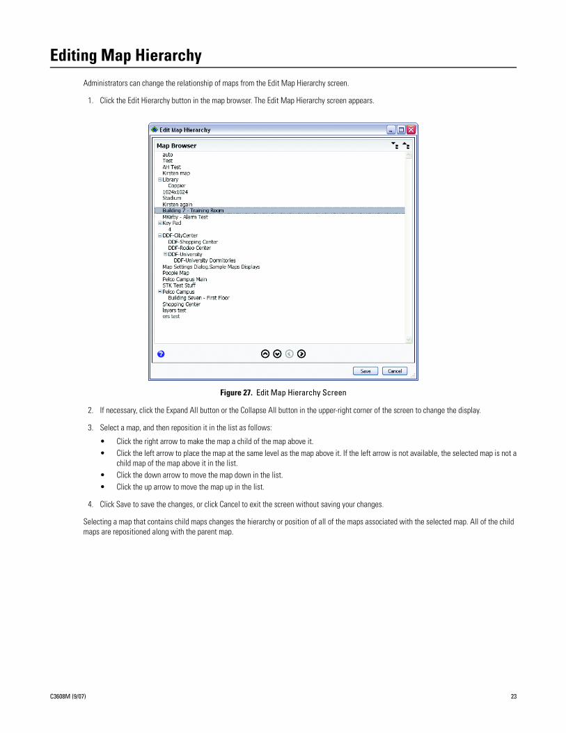
Editing Map HierarchyAdministrators can change the relationship of maps from the Edit Map Hierarchy screen.
1. Click the Edit Hierarchy button in the map browser. The Edit Map Hierarchy screen appears.
Figure 27. Edit Map Hierarchy Screen
2. If necessary, click the Expand All button or the Collapse All button in the upper-right corner of the screen to change the display.
3. Select a map, and then reposition it in the list as follows:
• Click the right arrow to make the map a child of the map above it.• Click the left arrow to place the map at the same level as the map above it. If the left arrow is not available, the selected map is not a
child map of the map above it in the list.• Click the down arrow to move the map down in the list.• Click the up arrow to move the map up in the list.
4. Click Save to save the changes, or click Cancel to exit the screen without saving your changes.
Selecting a map that contains child maps changes the hierarchy or position of all of the maps associated with the selected map. All of the child maps are repositioned along with the parent map.
C3608M (9/07) 23
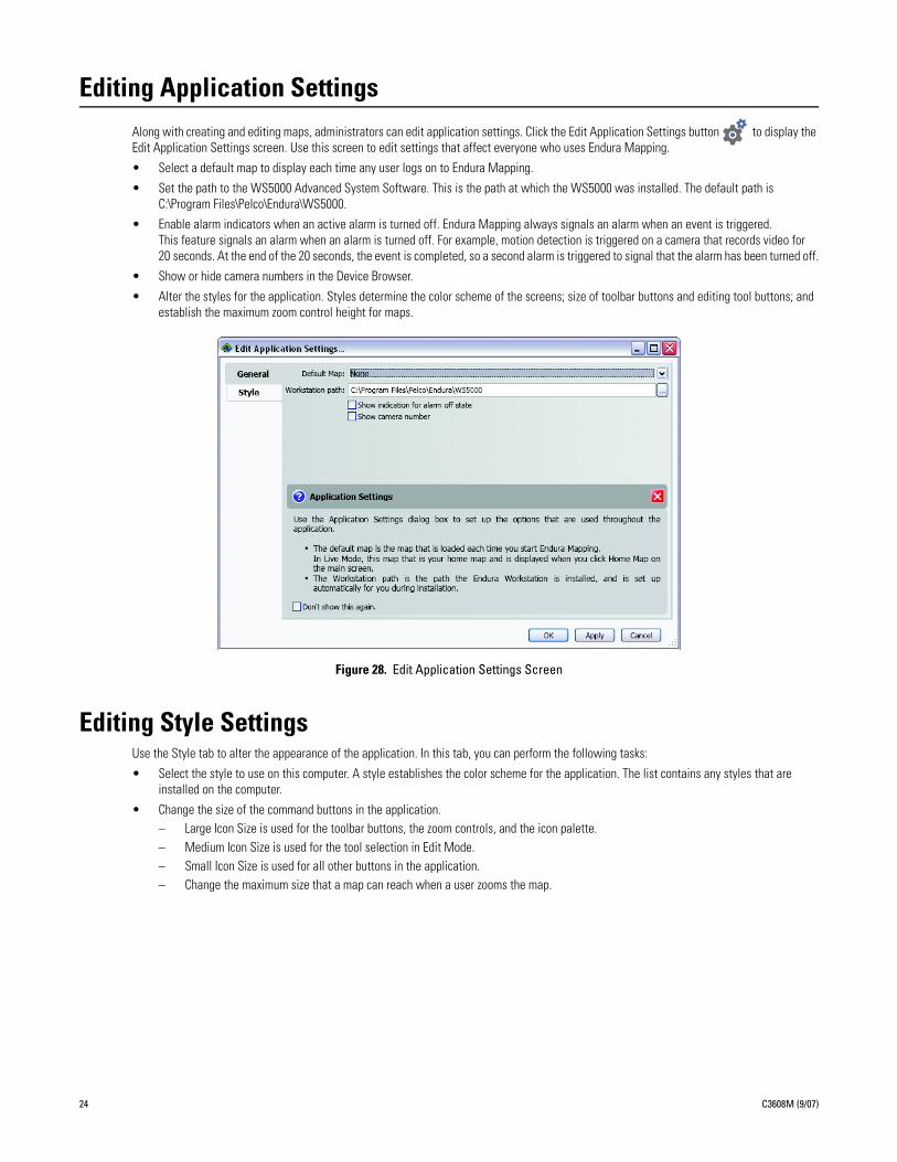
Editing Application SettingsAlong with creating and editing maps, administrators can edit application settings. Click the Edit Application Settings button to display the Edit Application Settings screen. Use this screen to edit settings that affect everyone who uses Endura Mapping.
• Select a default map to display each time any user logs on to Endura Mapping.
• Set the path to the WS5000 Advanced System Software. This is the path at which the WS5000 was installed. The default path is C:\Program Files\Pelco\Endura\WS5000.
• Enable alarm indicators when an active alarm is turned off. Endura Mapping always signals an alarm when an event is triggered. This feature signals an alarm when an alarm is turned off. For example, motion detection is triggered on a camera that records video for 20 seconds. At the end of the 20 seconds, the event is completed, so a second alarm is triggered to signal that the alarm has been turned off.
• Show or hide camera numbers in the Device Browser.
• Alter the styles for the application. Styles determine the color scheme of the screens; size of toolbar buttons and editing tool buttons; and establish the maximum zoom control height for maps.
Figure 28. Edit Application Settings Screen
Editing Style SettingsUse the Style tab to alter the appearance of the application. In this tab, you can perform the following tasks:
• Select the style to use on this computer. A style establishes the color scheme for the application. The list contains any styles that are installed on the computer.
• Change the size of the command buttons in the application.– Large Icon Size is used for the toolbar buttons, the zoom controls, and the icon palette.– Medium Icon Size is used for the tool selection in Edit Mode.– Small Icon Size is used for all other buttons in the application.– Change the maximum size that a map can reach when a user zooms the map.
24 C3608M (9/07)
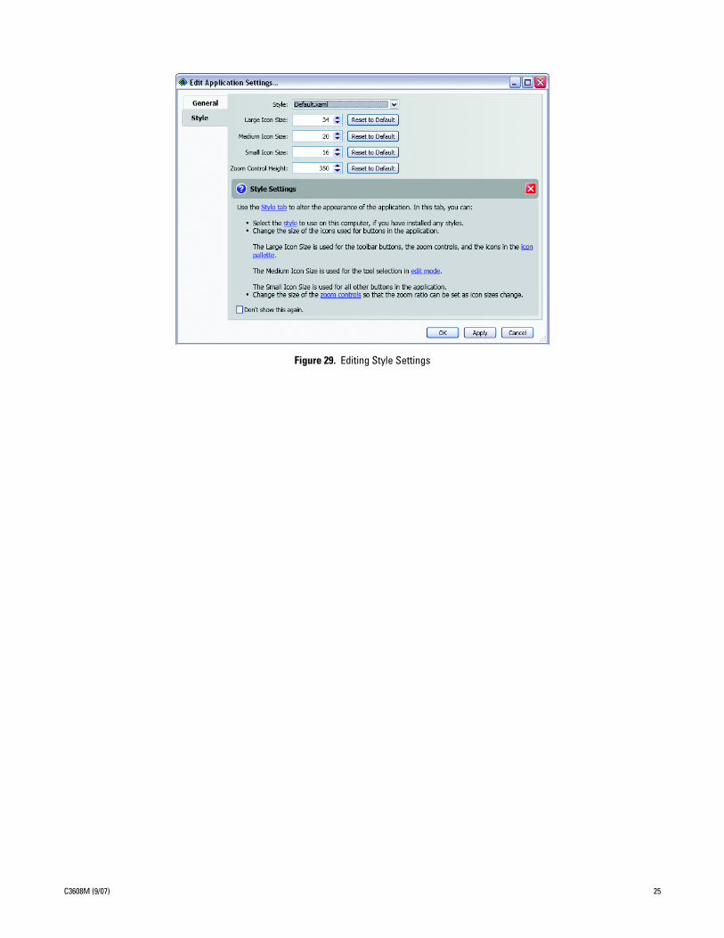
Figure 29. Editing Style Settings
C3608M (9/07) 25

Managing UsersUser permissions for Endura Mapping are controlled on the SM5000 Endura system manager and are set from the WS5000 advanced system software. To provide access to Endura Mapping, a system administrator can add permission for either of the following roles to any Endura user from the WS5000:
• View maps: Assign this permission to operators who will monitor video and alarms. Users with this permission cannot create, edit, or delete maps, nor can they edit application settings.
• Add and modify maps: Assign this permission to administrators who can view, create, edit, and delete maps, and who can edit application settings.
26 C3608M (9/07)
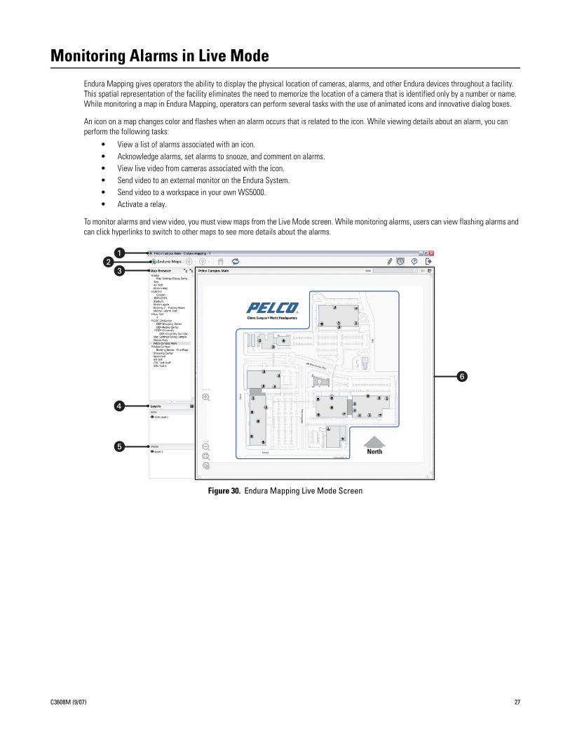
Monitoring Alarms in Live ModeEndura Mapping gives operators the ability to display the physical location of cameras, alarms, and other Endura devices throughout a facility. This spatial representation of the facility eliminates the need to memorize the location of a camera that is identified only by a number or name. While monitoring a map in Endura Mapping, operators can perform several tasks with the use of animated icons and innovative dialog boxes.
An icon on a map changes color and flashes when an alarm occurs that is related to the icon. While viewing details about an alarm, you can perform the following tasks:
• View a list of alarms associated with an icon.• Acknowledge alarms, set alarms to snooze, and comment on alarms.• View live video from cameras associated with the icon.• Send video to an external monitor on the Endura System.• Send video to a workspace in your own WS5000.• Activate a relay.
To monitor alarms and view video, you must view maps from the Live Mode screen. While monitoring alarms, users can view flashing alarms and can click hyperlinks to switch to other maps to see more details about the alarms.
Figure 30. Endura Mapping Live Mode Screen
C3608M (9/07) 27
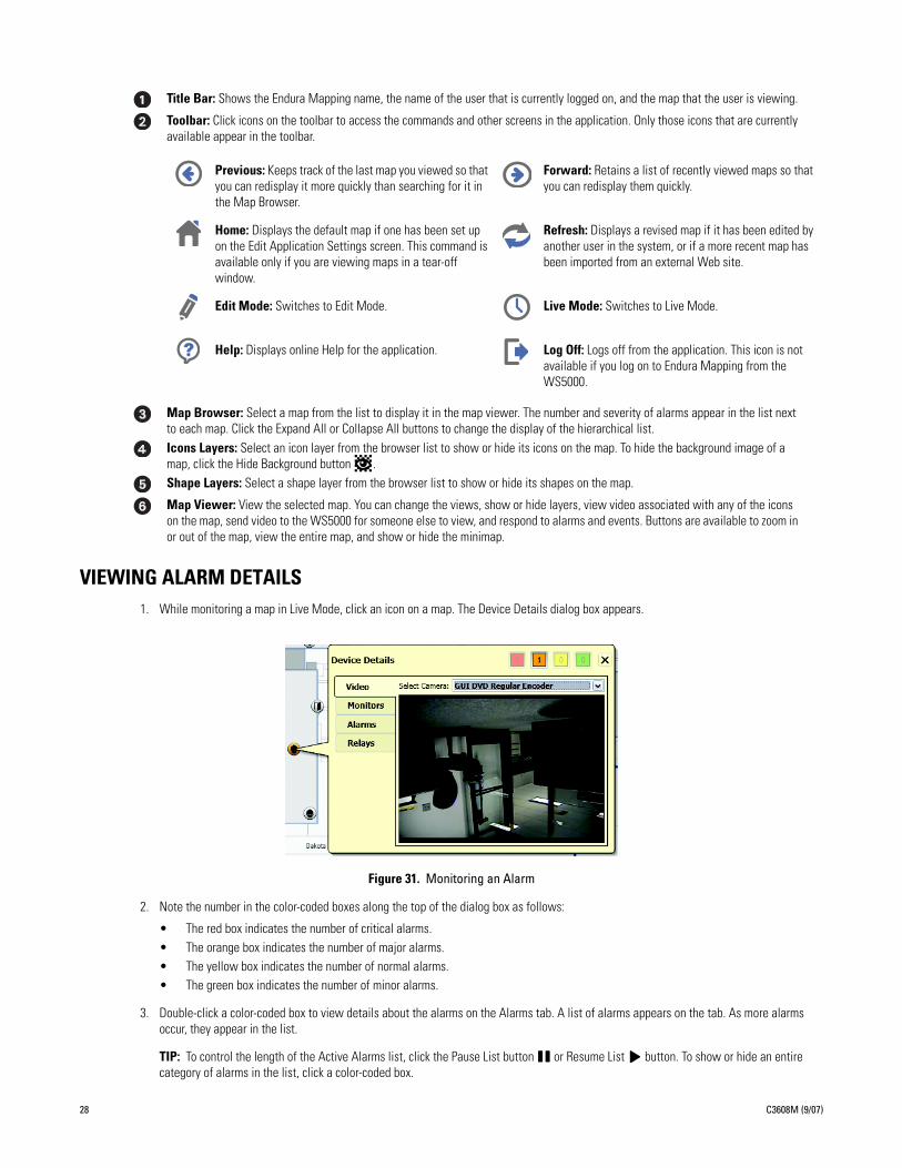
VIEWING ALARM DETAILS1. While monitoring a map in Live Mode, click an icon on a map. The Device Details dialog box appears.
Figure 31. Monitoring an Alarm
2. Note the number in the color-coded boxes along the top of the dialog box as follows:
• The red box indicates the number of critical alarms.• The orange box indicates the number of major alarms.• The yellow box indicates the number of normal alarms.• The green box indicates the number of minor alarms.
3. Double-click a color-coded box to view details about the alarms on the Alarms tab. A list of alarms appears on the tab. As more alarms occur, they appear in the list.
TIP: To control the length of the Active Alarms list, click the Pause List button or Resume List button. To show or hide an entire category of alarms in the list, click a color-coded box.
Title Bar: Shows the Endura Mapping name, the name of the user that is currently logged on, and the map that the user is viewing.
Toolbar: Click icons on the toolbar to access the commands and other screens in the application. Only those icons that are currently available appear in the toolbar.
Previous: Keeps track of the last map you viewed so that you can redisplay it more quickly than searching for it in the Map Browser.
Forward: Retains a list of recently viewed maps so that you can redisplay them quickly.
Home: Displays the default map if one has been set up on the Edit Application Settings screen. This command is available only if you are viewing maps in a tear-off window.
Refresh: Displays a revised map if it has been edited by another user in the system, or if a more recent map has been imported from an external Web site.
Edit Mode: Switches to Edit Mode. Live Mode: Switches to Live Mode.
Help: Displays online Help for the application. Log Off: Logs off from the application. This icon is not available if you log on to Endura Mapping from the WS5000.
Map Browser: Select a map from the list to display it in the map viewer. The number and severity of alarms appear in the list next to each map. Click the Expand All or Collapse All buttons to change the display of the hierarchical list.Icons Layers: Select an icon layer from the browser list to show or hide its icons on the map. To hide the background image of a map, click the Hide Background button .Shape Layers: Select a shape layer from the browser list to show or hide its shapes on the map.
Map Viewer: View the selected map. You can change the views, show or hide layers, view video associated with any of the icons on the map, send video to the WS5000 for someone else to view, and respond to alarms and events. Buttons are available to zoom in or out of the map, view the entire map, and show or hide the minimap.
28 C3608M (9/07)
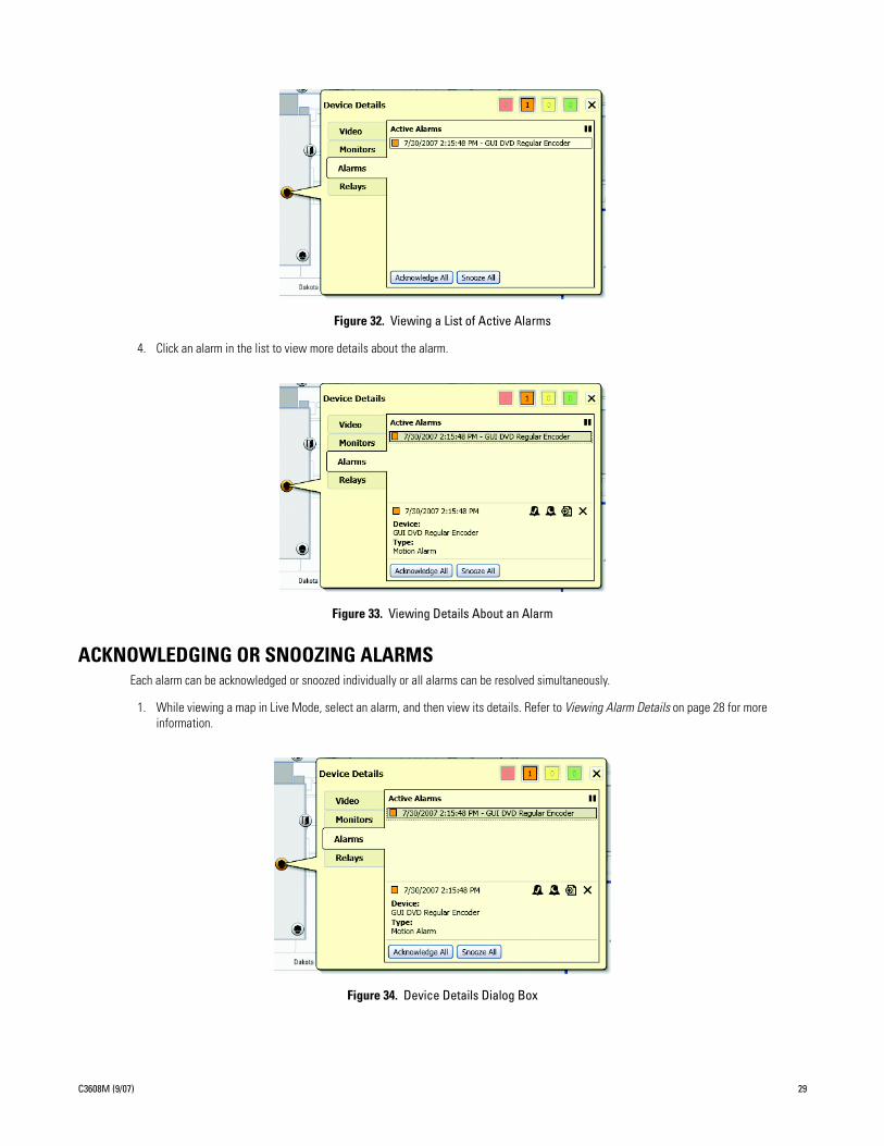
Figure 32. Viewing a List of Active Alarms
4. Click an alarm in the list to view more details about the alarm.
Figure 33. Viewing Details About an Alarm
ACKNOWLEDGING OR SNOOZING ALARMSEach alarm can be acknowledged or snoozed individually or all alarms can be resolved simultaneously.
1. While viewing a map in Live Mode, select an alarm, and then view its details. Refer to Viewing Alarm Details on page 28 for more information.
Figure 34. Device Details Dialog Box
C3608M (9/07) 29
2. Perform any of the following tasks from this tab:
• Acknowledge all of the alarms by clicking the Acknowledge All button.• Snooze all of the alarms by clicking the Snooze All button.• Acknowledge a specific alarm by clicking the Acknowledge Alarm button .• Snooze a specific alarm by clicking the Snooze Alarm button .• Hide the alarm details and return to the list view by clicking the Close Alarm Details button .
NOTE: The length of time that an alarm can be snoozed is set for each user in the Endura system. The default snooze time is one minute. To change this setting, refer to the WS5000 Operation manual.
3. Close the Device Details dialog box when you are done handling the alarms for this icon.
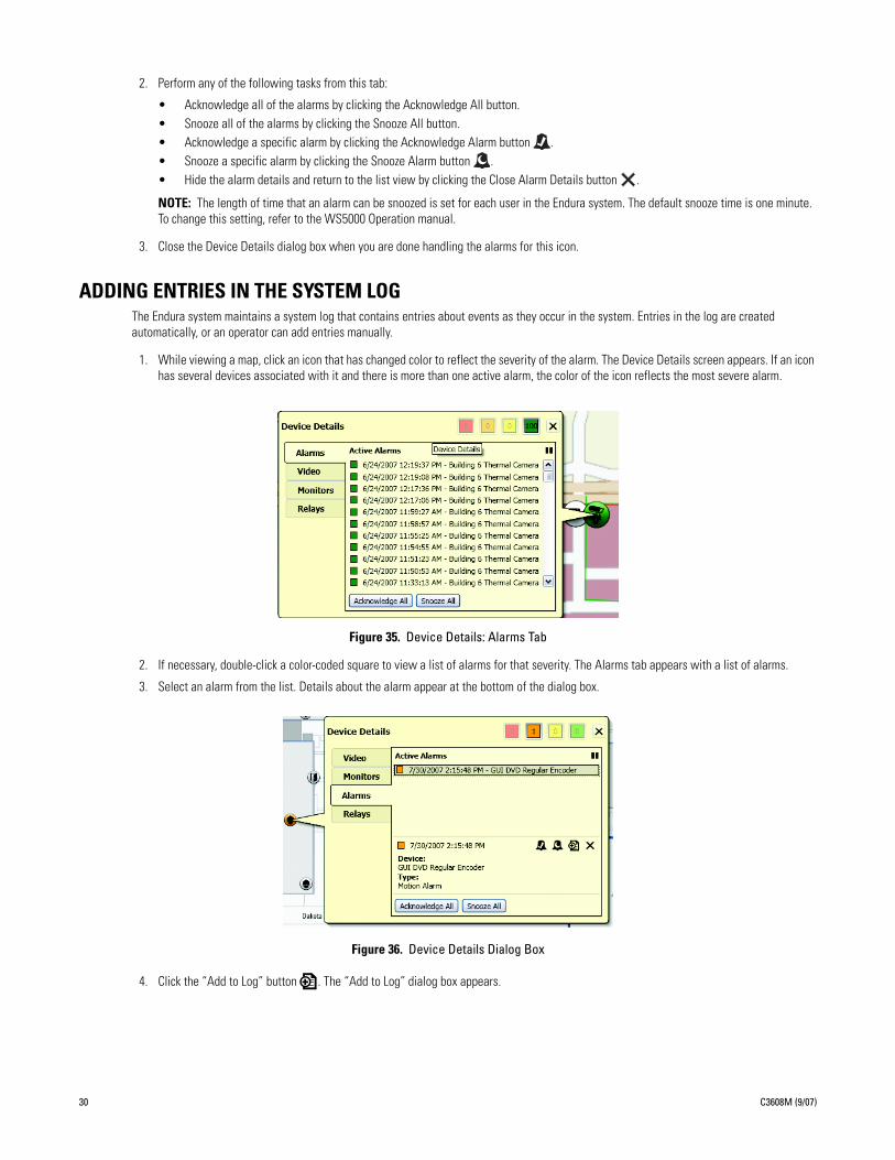
ADDING ENTRIES IN THE SYSTEM LOGThe Endura system maintains a system log that contains entries about events as they occur in the system. Entries in the log are created automatically, or an operator can add entries manually.
1. While viewing a map, click an icon that has changed color to reflect the severity of the alarm. The Device Details screen appears. If an icon has several devices associated with it and there is more than one active alarm, the color of the icon reflects the most severe alarm.
Figure 35. Device Details: Alarms Tab
2. If necessary, double-click a color-coded square to view a list of alarms for that severity. The Alarms tab appears with a list of alarms.
3. Select an alarm from the list. Details about the alarm appear at the bottom of the dialog box.
Figure 36. Device Details Dialog Box
4. Click the “Add to Log” button . The “Add to Log” dialog box appears.
30 C3608M (9/07)
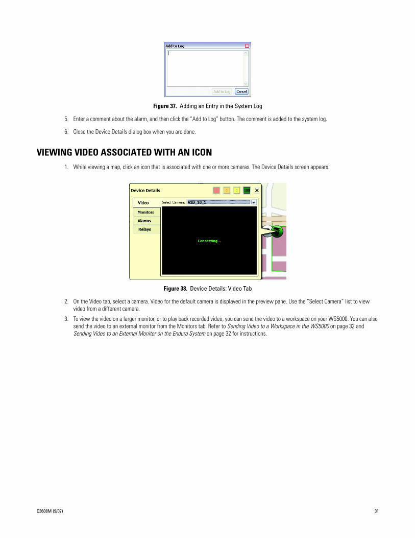
Figure 37. Adding an Entry in the System Log
5. Enter a comment about the alarm, and then click the “Add to Log” button. The comment is added to the system log.
6. Close the Device Details dialog box when you are done.
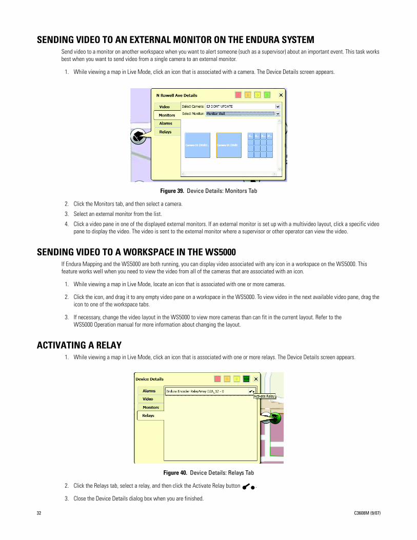
VIEWING VIDEO ASSOCIATED WITH AN ICON1. While viewing a map, click an icon that is associated with one or more cameras. The Device Details screen appears.
Figure 38. Device Details: Video Tab
2. On the Video tab, select a camera. Video for the default camera is displayed in the preview pane. Use the “Select Camera” list to view video from a different camera.
3. To view the video on a larger monitor, or to play back recorded video, you can send the video to a workspace on your WS5000. You can also send the video to an external monitor from the Monitors tab. Refer to Sending Video to a Workspace in the WS5000 on page 32 and Sending Video to an External Monitor on the Endura System on page 32 for instructions.
C3608M (9/07) 31
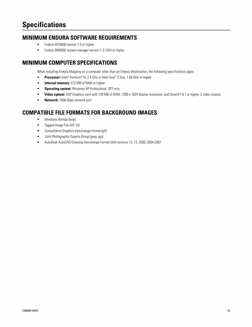
SENDING VIDEO TO AN EXTERNAL MONITOR ON THE ENDURA SYSTEMSend video to a monitor on another workspace when you want to alert someone (such as a supervisor) about an important event. This task works best when you want to send video from a single camera to an external monitor.
1. While viewing a map in Live Mode, click an icon that is associated with a camera. The Device Details screen appears.
Figure 39. Device Details: Monitors Tab
2. Click the Monitors tab, and then select a camera.
3. Select an external monitor from the list.
4. Click a video pane in one of the displayed external monitors. If an external monitor is set up with a multivideo layout, click a specific video pane to display the video. The video is sent to the external monitor where a supervisor or other operator can view the video.
SENDING VIDEO TO A WORKSPACE IN THE WS5000If Endura Mapping and the WS5000 are both running, you can display video associated with any icon in a workspace on the WS5000. This feature works well when you need to view the video from all of the cameras that are associated with an icon.
1. While viewing a map in Live Mode, locate an icon that is associated with one or more cameras.
2. Click the icon, and drag it to any empty video pane on a workspace in the WS5000. To view video in the next available video pane, drag the icon to one of the workspace tabs.
3. If necessary, change the video layout in the WS5000 to view more cameras than can fit in the current layout. Refer to the WS5000 Operation manual for more information about changing the layout.
ACTIVATING A RELAY1. While viewing a map in Live Mode, click an icon that is associated with one or more relays. The Device Details screen appears.
Figure 40. Device Details: Relays Tab
2. Click the Relays tab, select a relay, and then click the Activate Relay button .
3. Close the Device Details dialog box when you are finished.
32 C3608M (9/07)
Specifications
MINIMUM ENDURA SOFTWARE REQUIREMENTS• Endura WS5000 version 1.5 or higher
• Endura SM5000 system manager version 1.3.1024 or higher
MINIMUM COMPUTER SPECIFICATIONSWhen installing Endura Mapping on a computer other than an Endura Workstation, the following specifications apply.
• Processor: Intel® Pentium® IV, 2.4 GHz or Intel Core™ 2 Duo, 1.66 GHz or higher
• Internal memory: 512 MB of RAM or higher
• Operating system: Windows XP Professional, SP2 only
• Video system: AGP Graphics card with 128 MB of RAM, 1280 x 1024 display resolution, and DirectX® 8.1 or higher, 2 video outputs
• Network: 1000 Gbps network port
COMPATIBLE FILE FORMATS FOR BACKGROUND IMAGES• Windows Bitmap (bmp)
• Tagged Image File (tiff, tif)
• CompuServe Graphics Interchange Format (gif)
• Joint Photographic Experts Group (jpeg, jpg)
• AutoDesk AutoCAD Drawing Interchange Format (dxf) versions 12, 13, 2000, 2004-2007
C3608M (9/07) 33

PRODUCT WARRANTY AND RETURN INFORMATION
WARRANTY
Pelco will repair or replace, without charge, any merchandise proved defective in material orworkmanship for a period of one year after the date of shipment.
Exceptions to this warranty are as noted below:
• Five years on fiber optic products and TW3000 Series unshielded twisted pair transmissionproducts.
• Three years on Spectra® IV products.• Three years on Genex® Series products (multiplexers, server, and keyboard).• Three years on Camclosure® and fixed camera models, except the CC3701H-2,
CC3701H-2X, CC3751H-2, CC3651H-2X, MC3651H-2, and MC3651H-2X camera models,which have a five-year warranty.
• Three years on PMCL200/300/400 Series LCD monitors.• Two years on standard motorized or fixed focal length lenses.• Two years on Legacy®, CM6700/CM6800/CM9700 Series matrix, and DF5/DF8 Series fixed
dome products.• Two years on Spectra III™, Esprit®, ExSite®, and PS20 scanners, including when used in
continuous motion applications.• Two years on Esprit and WW5700 Series window wiper (excluding wiper blades).• Two years (except lamp and color wheel) on Digital Light Processing (DLP®) displays.
The lamp and color wheel will be covered for a period of 90 days. The air filter is notcovered under warranty.
• Eighteen months on DX Series digital video recorders, NVR300 Series network videorecorders, and Endura™ Series distributed network-based video products.
• One year (except video heads) on video cassette recorders (VCRs). Video heads will becovered for a period of six months.
• Six months on all pan and tilts, scanners or preset lenses used in continuous motionapplications (that is, preset scan, tour and auto scan modes).
Pelco will warrant all replacement parts and repairs for 90 days from the date of Pelcoshipment. All goods requiring warranty repair shall be sent freight prepaid to Pelco, Clovis,California. Repairs made necessary by reason of misuse, alteration, normal wear, or accidentare not covered under this warranty.
Pelco assumes no risk and shall be subject to no liability for damages or loss resulting fromthe specific use or application made of the Products. Pelco’s liability for any claim, whetherbased on breach of contract, negligence, infringement of any rights of any party or product lia-bility, relating to the Products shall not exceed the price paid by the Dealer to Pelco for suchProducts. In no event will Pelco be liable for any special, incidental or consequential damages(including loss of use, loss of profit and claims of third parties) however caused, whether bythe negligence of Pelco or otherwise.
The above warranty provides the Dealer with specific legal rights. The Dealer may also haveadditional rights, which are subject to variation from state to state.
If a warranty repair is required, the Dealer must contact Pelco at (800) 289-9100 or(559) 292-1981 to obtain a Repair Authorization number (RA), and provide the followinginformation:
1. Model and serial number2. Date of shipment, P.O. number, Sales Order number, or Pelco invoice number3. Details of the defect or problem
If there is a dispute regarding the warranty of a product which does not fall under thewarranty conditions stated above, please include a written explanation with the product whenreturned.
Method of return shipment shall be the same or equal to the method by which the item wasreceived by Pelco.
RETURNS
In order to expedite parts returned to the factory for repair or credit, please call the factory at(800) 289-9100 or (559) 292-1981 to obtain an authorization number (CA number if returned forcredit, and RA number if returned for repair).
All merchandise returned for credit may be subject to a 20% restocking and refurbishingcharge.
Goods returned for repair or credit should be clearly identified with the assigned CA or RAnumber and freight should be prepaid. Ship to the appropriate address below.
If you are located within the continental U.S., Alaska, Hawaii or Puerto Rico, send goods to:Service DepartmentPelco3500 Pelco WayClovis, CA 93612-5699
If you are located outside the continental U.S., Alaska, Hawaii or Puerto Rico and are instructedto return goods to the USA, you may do one of the following:
If the goods are to be sent by a COURIER SERVICE, send the goods to:Pelco3500 Pelco WayClovis, CA 93612-5699 USA
If the goods are to be sent by a FREIGHT FORWARDER, send the goods to:Pelco c/o Expeditors473 Eccles AvenueSouth San Francisco, CA 94080 USAPhone: 650-737-1700Fax: 650-737-0933
The materials used in the manufacture of this document and its components are compliant to the requirements of Directive 2002/95/EC.
This equipment contains electrical or electronic components that must be recycled properly to comply with Directive 2002/96/EC of the European Union regarding the disposal of waste electrical and electronic equipment (WEEE). Contact your local dealer for procedures for recycling this equipment.
REVISION HISTORY
Manual # Date CommentsC3608M 9/07 Original version.
Pelco, the Pelco logo, Camclosure, Esprit, Genex, Legacy, ExSite, and Spectra are registered trademarks of Pelco. ©Copyright 2007, Pelco.Endura and Spectra III are trademarks of Pelco. All rights reserved.DLP is a registered trademark of Texas Instruments, Inc.AutoCAD is registered trademark of AutoDesk Inc. Illustrator is a registered trademark of Adobe, Inc.Windows and DirectX are registered trademarks of Microsoft Corporation in the United States and/or other countries.Intel and Pentium are registered trademarks of Intel Corporation.Core is a trademark of Intel Corporation.

Worldwide Headquarters3500 Pelco Way
Clovis, California 93612 USA
USA & CanadaTel: 800/289-9100Fax: 800/289-9150
InternationalTel: 1-559/292-1981Fax: 1-559/348-1120
www.pelco.com
ISO9001
Australia | Canada | Finland | France | Germany | Italy | Macau | The Netherlands | Russia | Singapore
South Africa | Spain | Sweden | United Arab Emirates | United Kingdom | United States