Embed Size (px)
Citation preview
Torsten Braun, Michel Diaz, Jose Enrıquez-Gabeiras, and Thomas Staub
End-to-End Quality of ServiceOver Heterogeneous Networks
February 12, 2008
Springer


Foreword
v


Preface
The Internet has evolved from an academic network for data applications such asfile transfer and net news, to a global general-purpose network used for a varietyof different applications covering electronic mail, voiceover IP, television, peer-to-peer file sharing, video streaming and many more. The heterogeneity of appli-cations results in rather different application requirements in terms of bandwidth,delay, loss, etc. Ideally, the underlying network supportssuch Quality-of-Serviceparameters such that applications can request the desired services from the network,and do not need to take actions by themselves to achieve the desired communica-tion quality. Initially, the Internet was not designed to support Quality-of-Service,and only since the last decade have appropriate mechanisms been developed. Thosemechanisms mainly operate on the Internet Protocol (IP) level, but also network-specific mechanisms—e.g., targeted to particular wired/wireless access networktechnologies—are required.
The goal of the European 6th Framework Programme (FP6) Integrated Project”End-to-end Quality of Service Support over HeterogeneousNetworks” (EuQoS)was to develop, implement, and evaluate concepts and mechanisms to support QoSend-to-end, meaning that QoS mechanisms in end systems, access networks, inter-domain links and within domains must be supported. The EuQoSproject developedan impressive set of innovative solutions and novel scientific ideas to support end-to-end QoS in the Internet. New mechanisms and concepts were designed and imple-mented in a European-wide distributed testbed. In additionto the rather technicaldesign and implementation work, the project also developedtraining material in-troducing basic QoS mechanisms and techniques. Several e-learning modules weredeveloped and are currently being used at several partner universities for teachingon MSc or PhD levels.
The significant technical and educational results achievedduring the EuQoSproject, motivated us to use the gained knowledge and experiences of the projectpartners and write this book on end-to-end QoS in heterogeneous IP networks. Thebook basically consists of three parts. In Chapters 1-4, we discuss QoS mecha-nisms and protocols such as scheduling schemes, QoS architectures metrics andmeasurement techniques, traffic engineering and signalling protocols, and the latest
vii
viii Preface
standardisation activities. Chapter 5 describes related work and recent developmentin the area of transport protocols, in particular how TCP canbe optimised towardsQoS support and fairness. The EuQoS system presented in Chapter 6 extends andcombines the basic mechanisms discussed in the previous chapters. We show how acombination of different QoS enabling mechanisms and protocols can be used andextended to build a comprehensive end-to-end QoS architecture over heterogeneouswired/wireless access networks. To evaluate QoS mechanisms and architectures, ap-propriate evaluation schemes are required. The two chapters in the annex describehow simulation—in particular the well-known network simulator ns-2—as well asemulation techniques can be used for tests and evaluations.
This book, which is based on the achievements of the EuQoS project, would nothave been possible to compile without the funding from the European Commission,as well as the tremendous efforts and enthusiasm of all the people involved in theproject. Special thanks to Mark Gunter for proof-reading the text contributions tothis book.
Torsten BraunMichel Diaz
Jose Enriquez GabeirasBern, Toulouse, Madrid. January 2008. Thomas Staub

Acknowledgements
The book editors and authors would like to thank all people who were involved inthe EuQoS project:
• Telefonica I+D: Jose Enrıquez Gabeiras, Francisco Javier Ramon Salguero, Ger-ardo Garcıa de Blas, Antonio J. Elizondo Armengol, Francisco, Romero Bueno,Jesus Bravo lvarez, Jorge Andres Colas, MarıaAngeles, Callejo Rodrıguez,Marıa Luisa Garcıa Osma
• University of Pisa (CPR/UoPisa):Enzo Mingozzi, Giovanni Stea, LucianoLenzini, Luca Bisti, Claudio Cicconetti, Linda Martorini,Abraham Gebrehiwot,Simone Bisogni, Paolo Sozzi
• Elsag Datamat:Enrico Angori, Giuseppe Martufi, Marco Carusio, AlessandroGiorgini, Andrea Paselli, Giovanni Saccomandi, Marco Mauro
• CNRS (LAAS-CNRS, ENSICA): Michel Diaz, Florin Racaru, Ernesto Expos-ito, Philippe Owezarski, Patrick Senac , Christophe Chassot , Nicolas Larrieu,Laurent Dairaine, Mathieu Gineste, Nicolas Van Wambeke, Slim Abdellatif,Sebastien Ardon, Roberto Willrich, Guillaume Auriol, Silvia Farraposo
• France Telecom R&D:Olivier Dugeon, Walid Htira, Michel Bourbao, Pascal LeGuern, Jean-Louis Le Roux, Stephane Statiotis, Regis Fr´echin, Claire Teisseire
• Polska Telefonia Cyfrowa (ERA):Michal Obuchowicz, Robert Parzydo , AdamFlizikowski, Edyta Rafalska, Karol Jez, Krzysztof Horszczaruk, Krzysztof Bro-narski, Krzysztof Samp, Maciej Rozowicz, Michal Dudzinski, Pawel Caban, Pi-otr Zadroga, Slawomir Tkacz
• Martel: Martin Potts, Mark Guenter, Sandra Wittwer• NICTA: Emmanuel Lochin, Guillaume Jourjon, Sebastien Ardon, Ernesto Ex-
posito, Feiselia Tan, Laurent Dairaine• PointerCom: Roberto Marega, Stefano Salsano, Donald Papalilo, Gianluca Mar-
tiniello, Valeria Calcagni• Polish Telecom R&D: Zbigniew Kopertowski, Jaroslaw Kowalczyk, Tomasz
Ciszkowski
ix

x Acknowledgements
• Portugal Telecom Inovacao (PTIN): Jorge Carapinha, Nuno Carapeto, PauloLoureiro, Arnaldo Santos, Eduardo Silva, Fernando Santiago, Helena PaulaMatos, Hugo Manaia, Isabel Borges, Jacinto Barbeira, Filipe Peixinho.
• Red Zinc: Donal Morris, Brian Widger, Diarmuid O Neill, Lea Compin, OscarCuidad
• Silogic: Laurent Baresse, Benoıt Baurens, Jean-Philippe Darmet, Yannick Lizzi,Francois Meaude
• INDRA ( previously SOLUZIONA): Ignacio Fresno, Jaime Orozco, Luis Col-lantes Abril, Pablo Vaquero Barbon, Ruben Romero San Martın, Jorge Alonso,Maria Lurdes Sousa, Raul Manzano Barroso
• Telscom AG:Sathya Rao, Marcin Michalak• Technical University of Catalonia (UPC): Jordi Domingo-Pascual, Lorand
Jakab, Marcelo Yannuzzi, Rene Serral-Gracia, Xavier Masip-Bruin• University of Bern: Torsten Braun, Thomas Staub, Dragan Milic, Marc Brogle,
Marc-Alain Steinemann, Thomas Bernoulli, Gerald Wagenknecht, Markus Wulff,Patrick Lauer, Markus Anwander, Matthias Scheidegger
• University of Paderborn/C-LAB: Isabell Jahnich, Achim Rettberg, Chris Loeser,Michael Ditze, Kay Klobedanz, Sebastian Seitz, Andreas Konig, Volker Spaar-mann, Matthias Grawinkel
• University of Rome: Antonio Pietrabissa, Francesco Delli Priscoli, Sabrina Gi-ampaoletti, Emiliano Guainella, Erasmo Di Santo, Gianfranco Santoro, IlariaMarchetti, Massimiliano Rossi
• Universidade de Coimbra: Edmundo Monteiro, Luıs Cordeiro, Bruno Car-valho, Fernando Boavida, Gabriela Batista Leao, Isidro Caramelo, Jian Zhang,Jorge Sa Silva, Marilia Curado, Maxwel Carmo, Paulo Simoes, Romulo Ribeiro,Vitor Bernardo, David Palma, Rui Vilao, Luıs Conceicao
• Warsaw University of Technology: Wojciech Burakowski, Andrzej Beben,Halina Tarasiuk, Jaroslaw Sliwinski, Jordi Mongay Batalla, Marek Dabrowski,Piotr Krawiec, Robert Janowski
• Ericsson: Antoine de Poorter, Julio Lopez Roldan, Miguel Angel Recio, JesusRenero Quintero, Jose Luis Agundez
• Hospital Divino Espirito Santo: Jose Manuel Ponte, Antonio Vasco Viveiros,Carlos P. Duarte, Paula Maciel, Jose M. Jesus Silva, Maura Medeiros, MariaDulce Raposo
Contents
1 Motivation and Basics . . . . . . . . . . . . . . . . . . . . . . . . . . . . . . . . . . . . . . . . . . 11.1 Quality of Service and its Parameters . . . . . . . . . . . . . . . .. . . . . . . . . . 1
1.1.1 Delay and Delay Variations in End-to-End Packet Delivery . 21.1.2 Bandwidth and Packet Loss Ratio . . . . . . . . . . . . . . . . . . .. . . 4
1.2 Applications’ QoS Requirements . . . . . . . . . . . . . . . . . . . .. . . . . . . . . 51.2.1 Types of Network Applications . . . . . . . . . . . . . . . . . . . .. . . . 51.2.2 QoS Requirements of Applications . . . . . . . . . . . . . . . . .. . . . 7
1.3 Packet Scheduling in Network Elements . . . . . . . . . . . . . . .. . . . . . . . 91.3.1 (Non)Work-conserving Scheduling Disciplines . . . . .. . . . . . 91.3.2 Fairness . . . . . . . . . . . . . . . . . . . . . . . . . . . . . . . . . . . . . .. . . . . . 101.3.3 Scheduling Disciplines . . . . . . . . . . . . . . . . . . . . . . . . .. . . . . . 111.3.4 Packet Dropping . . . . . . . . . . . . . . . . . . . . . . . . . . . . . . . .. . . . 12
1.4 Quality-of-Service Architectures . . . . . . . . . . . . . . . . .. . . . . . . . . . . . . 131.4.1 Integrated Services . . . . . . . . . . . . . . . . . . . . . . . . . . . .. . . . . . 131.4.2 Differentiated Services. . . . . . . . . . . . . . . . . . . . . . . .. . . . . . . . 151.4.3 End-To-End QoS Mechanisms . . . . . . . . . . . . . . . . . . . . . . .. . 17
1.5 Implementation and Performance of QoS-aware Applications. . . . . . 191.5.1 Prequisites for Successful QoS Applications . . . . . . .. . . . . . . 191.5.2 Media Scaling . . . . . . . . . . . . . . . . . . . . . . . . . . . . . . . . . .. . . . . 191.5.3 Applications’ Performance Gain Due to QoS . . . . . . . . . .. . . 201.5.4 Summary . . . . . . . . . . . . . . . . . . . . . . . . . . . . . . . . . . . . . . .. . . . 22
1.6 Structure of the Book . . . . . . . . . . . . . . . . . . . . . . . . . . . . . .. . . . . . . . . 22
2 QoS Measurements in IP-based Networks. . . . . . . . . . . . . . . . . . . . . . . . . 252.1 Introduction . . . . . . . . . . . . . . . . . . . . . . . . . . . . . . . . . . . .. . . . . . . . . . . 252.2 Measurement Metrics . . . . . . . . . . . . . . . . . . . . . . . . . . . . . .. . . . . . . . . 26
2.2.1 Network Level . . . . . . . . . . . . . . . . . . . . . . . . . . . . . . . . . .. . . . 262.2.2 Call level . . . . . . . . . . . . . . . . . . . . . . . . . . . . . . . . . . . . .. . . . . . 302.2.3 User Level . . . . . . . . . . . . . . . . . . . . . . . . . . . . . . . . . . . . .. . . . . 32
2.3 Measurement Techniques . . . . . . . . . . . . . . . . . . . . . . . . . . .. . . . . . . . . 362.3.1 Previous Considerations . . . . . . . . . . . . . . . . . . . . . . . .. . . . . . 36
xi

xii Contents
2.3.2 Base Techniques . . . . . . . . . . . . . . . . . . . . . . . . . . . . . . . .. . . . . 392.3.3 Active Measurements . . . . . . . . . . . . . . . . . . . . . . . . . . . .. . . . . 412.3.4 Passive Measurements . . . . . . . . . . . . . . . . . . . . . . . . . . .. . . . . 47
2.4 Conclusions . . . . . . . . . . . . . . . . . . . . . . . . . . . . . . . . . . . . .. . . . . . . . . . 51
3 Traffic Engineering . . . . . . . . . . . . . . . . . . . . . . . . . . . . . . . . . . . . . . . . . . . . . 533.1 Introduction . . . . . . . . . . . . . . . . . . . . . . . . . . . . . . . . . . . .. . . . . . . . . . . 533.2 A Motivating Example . . . . . . . . . . . . . . . . . . . . . . . . . . . . . .. . . . . . . . 543.3 Multi-Protocol Label Switching Architecture . . . . . . . .. . . . . . . . . . . 56
3.3.1 The Forwarding Component . . . . . . . . . . . . . . . . . . . . . . . .. . . 573.3.2 The Control Component . . . . . . . . . . . . . . . . . . . . . . . . . . .. . . 593.3.3 MPLS Optimisation . . . . . . . . . . . . . . . . . . . . . . . . . . . . . .. . . . 60
3.4 MPLS-based Traffic Engineering . . . . . . . . . . . . . . . . . . . . .. . . . . . . . 623.4.1 Constraint-Based Routing . . . . . . . . . . . . . . . . . . . . . . .. . . . . 623.4.2 Explicit Route Signalling . . . . . . . . . . . . . . . . . . . . . . .. . . . . . 663.4.3 Traffic Engineering Practices . . . . . . . . . . . . . . . . . . . .. . . . . . 69
3.5 Traffic Engineering and Quality of Service . . . . . . . . . . . .. . . . . . . . . 713.5.1 QoS Support over MPLS . . . . . . . . . . . . . . . . . . . . . . . . . . . .. . 723.5.2 Traffic Engineering Extensions for DiffServ . . . . . . . .. . . . . . 74
3.6 Conclusions . . . . . . . . . . . . . . . . . . . . . . . . . . . . . . . . . . . . .. . . . . . . . . . 78
4 Signalling . . . . . . . . . . . . . . . . . . . . . . . . . . . . . . . . . . . . . . . . . . . . . . . . . . .. . 794.1 Introduction . . . . . . . . . . . . . . . . . . . . . . . . . . . . . . . . . . . .. . . . . . . . . . . 794.2 Session Initiation Protocol (SIP) . . . . . . . . . . . . . . . . . .. . . . . . . . . . . . 80
4.2.1 SIP and Its Value Propositions . . . . . . . . . . . . . . . . . . . .. . . . . 804.2.2 Protocol Components . . . . . . . . . . . . . . . . . . . . . . . . . . . .. . . . . 814.2.3 SIP Messages . . . . . . . . . . . . . . . . . . . . . . . . . . . . . . . . . . .. . . . 844.2.4 Session Description . . . . . . . . . . . . . . . . . . . . . . . . . . . .. . . . . . 874.2.5 Establishment of a SIP Session . . . . . . . . . . . . . . . . . . . .. . . . . 884.2.6 SIP’s Extension . . . . . . . . . . . . . . . . . . . . . . . . . . . . . . . .. . . . . . 91
4.3 The Next Steps In Signalling (NSIS) . . . . . . . . . . . . . . . . . .. . . . . . . . 914.3.1 Background and main Characteristics . . . . . . . . . . . . . .. . . . . 914.3.2 Background and Main Characteristics . . . . . . . . . . . . . .. . . . . 924.3.3 Overview of Signalling Scenarios and Protocol Structure . . . 954.3.4 The NSIS Layer Transport Protocol . . . . . . . . . . . . . . . . .. . . . 96
4.4 Common Open Policy Service (COPS) . . . . . . . . . . . . . . . . . . .. . . . . 1044.4.1 COPS Overview . . . . . . . . . . . . . . . . . . . . . . . . . . . . . . . . . .. . . 1044.4.2 Basic Model . . . . . . . . . . . . . . . . . . . . . . . . . . . . . . . . . . . .. . . . 1054.4.3 COPS Protocol . . . . . . . . . . . . . . . . . . . . . . . . . . . . . . . . . .. . . . 1064.4.4 COPS Messages . . . . . . . . . . . . . . . . . . . . . . . . . . . . . . . . . .. . . 1104.4.5 Common Operation . . . . . . . . . . . . . . . . . . . . . . . . . . . . . . .. . . 1134.4.6 Illustrative Examples, Using COPS for RSVP . . . . . . . . .. . . 114
4.5 Conclusions . . . . . . . . . . . . . . . . . . . . . . . . . . . . . . . . . . . . .. . . . . . . . . . 116
Contents xiii
5 Enhanced Transport Protocols. . . . . . . . . . . . . . . . . . . . . . . . . . . . . . . . . . . 1175.1 Introduction . . . . . . . . . . . . . . . . . . . . . . . . . . . . . . . . . . . .. . . . . . . . . . . 1175.2 State of the Art of Transport Protocols . . . . . . . . . . . . . . .. . . . . . . . . . 118
5.2.1 TCP and UDP . . . . . . . . . . . . . . . . . . . . . . . . . . . . . . . . . . . . .. . 1195.2.2 TCP Evolution . . . . . . . . . . . . . . . . . . . . . . . . . . . . . . . . . .. . . . 1205.2.3 SCTP . . . . . . . . . . . . . . . . . . . . . . . . . . . . . . . . . . . . . . . . . .. . . . 1225.2.4 DCCP. . . . . . . . . . . . . . . . . . . . . . . . . . . . . . . . . . . . . . . . . .. . . . 1235.2.5 Discussion . . . . . . . . . . . . . . . . . . . . . . . . . . . . . . . . . . . .. . . . . . 124
5.3 Transport Mechanisms . . . . . . . . . . . . . . . . . . . . . . . . . . . . .. . . . . . . . . 1245.3.1 Overview . . . . . . . . . . . . . . . . . . . . . . . . . . . . . . . . . . . . . .. . . . . 1245.3.2 Congestion Control Mechanisms . . . . . . . . . . . . . . . . . . .. . . . 1265.3.3 Reliability Mechanisms . . . . . . . . . . . . . . . . . . . . . . . . .. . . . . . 1275.3.4 Discussion . . . . . . . . . . . . . . . . . . . . . . . . . . . . . . . . . . . .. . . . . . 128
5.4 Enhanced Transport Protocol Mechanisms. . . . . . . . . . . . .. . . . . . . . . 1295.4.1 TFRC and gTFRC, a QoS-aware Congestion Control . . . . . .1295.4.2 Application-Aware Transport Mechanisms . . . . . . . . . .. . . . . 130
5.5 Conclusion . . . . . . . . . . . . . . . . . . . . . . . . . . . . . . . . . . . . . .. . . . . . . . . . 136
6 The EuQoS System. . . . . . . . . . . . . . . . . . . . . . . . . . . . . . . . . . . . . . . . . . . . . 1376.1 Introduction . . . . . . . . . . . . . . . . . . . . . . . . . . . . . . . . . . . .. . . . . . . . . . . 1386.2 Architecture . . . . . . . . . . . . . . . . . . . . . . . . . . . . . . . . . . . .. . . . . . . . . . . 139
6.2.1 Goals and Requirements . . . . . . . . . . . . . . . . . . . . . . . . . .. . . . 1396.2.2 Functional Blocks and their Main Functions . . . . . . . . .. . . . . 1406.2.3 Control Plane Elements: RM and RA . . . . . . . . . . . . . . . . . .. 143
6.3 Provisioning, Invocation, and Operation, Administration andManagement . . . . . . . . . . . . . . . . . . . . . . . . . . . . . . . . . . . . . . . . .. . . . . 1456.3.1 Provisioning Process . . . . . . . . . . . . . . . . . . . . . . . . . . .. . . . . . 1466.3.2 Invocation Process . . . . . . . . . . . . . . . . . . . . . . . . . . . . .. . . . . . 1526.3.3 Operation, Administration and Management . . . . . . . . .. . . . . 156
6.4 End-to-End Classes of Service in Heterogeneous Networks . . . . . . . 1566.4.1 End-to-end Classes of Service in EuQoS . . . . . . . . . . . . .. . . . 1576.4.2 QoS Mechanisms and Algorithms for Specification of e2e
Classes of Service . . . . . . . . . . . . . . . . . . . . . . . . . . . . . . . . . . .. 1606.4.3 Implementation of e2e Classes of Service in Underlying
Technologies . . . . . . . . . . . . . . . . . . . . . . . . . . . . . . . . . . . . . . .. 1626.5 EuQoS Enhanced Transport Protocol . . . . . . . . . . . . . . . . . .. . . . . . . . 168
6.5.1 Introduction . . . . . . . . . . . . . . . . . . . . . . . . . . . . . . . . . .. . . . . . . 1686.5.2 Enhanced Transport Protocol Services for EuQoS . . . . .. . . . 1696.5.3 Services for Streaming/Non-Streaming Applications. . . . . . 170
6.6 Multicast . . . . . . . . . . . . . . . . . . . . . . . . . . . . . . . . . . . . . . .. . . . . . . . . . 1716.6.1 Application Layer Multicast . . . . . . . . . . . . . . . . . . . . .. . . . . . 1726.6.2 Application Layer Multicast in the EuQoS System . . . . .. . . 1736.6.3 Multicast Middleware . . . . . . . . . . . . . . . . . . . . . . . . . . .. . . . . 1756.6.4 Introducing QoS to Multicast Middleware . . . . . . . . . . .. . . . 178
6.7 Telemedicine Application . . . . . . . . . . . . . . . . . . . . . . . . .. . . . . . . . . . . 180

xiv Contents
6.7.1 Telemedicine – the Case for Application-Driven QoS . .. . . 1806.7.2 Overview of Medigraf . . . . . . . . . . . . . . . . . . . . . . . . . . . .. . . . 1806.7.3 Medigraf Adaptation to EuQoS . . . . . . . . . . . . . . . . . . . . .. . . 182
6.8 Conclusions . . . . . . . . . . . . . . . . . . . . . . . . . . . . . . . . . . . . .. . . . . . . . . . 184
7 Summary and Outlook . . . . . . . . . . . . . . . . . . . . . . . . . . . . . . . . . . . . . . . . . 187
A Implementing Protocols on Network Simulators . . . . . . . . . . . . . . . . . . . 189A.1 Main Simulation Terms and Concepts . . . . . . . . . . . . . . . . . .. . . . . . . 189
A.1.1 Simulation Process . . . . . . . . . . . . . . . . . . . . . . . . . . . . .. . . . . . 190A.1.2 Simulation Types . . . . . . . . . . . . . . . . . . . . . . . . . . . . . . .. . . . . 190
A.2 Network Simulation . . . . . . . . . . . . . . . . . . . . . . . . . . . . . . .. . . . . . . . . 191A.2.1 Parallel/Distributed versus Serial Execution of Simulations . 192A.2.2 Packet-Level, Fluid-Based and Hybrid Model Simulation . . . 192A.2.3 Simulation Speedup . . . . . . . . . . . . . . . . . . . . . . . . . . . . .. . . . . 193A.2.4 Network Simulation in Research . . . . . . . . . . . . . . . . . . .. . . . 193A.2.5 Simulation for Education Purposes . . . . . . . . . . . . . . . .. . . . . 195
A.3 Network Simulators . . . . . . . . . . . . . . . . . . . . . . . . . . . . . . .. . . . . . . . . 195A.3.1 GloMoSim and Qualnet . . . . . . . . . . . . . . . . . . . . . . . . . . . .. . . 195A.3.2 JiST/SWANS . . . . . . . . . . . . . . . . . . . . . . . . . . . . . . . . . . . .. . . 196A.3.3 Scalable Simulation Framework (SSF) and SSFNet . . . . .. . . 196A.3.4 OMNeT++ and OMNEST . . . . . . . . . . . . . . . . . . . . . . . . . . . . . 196
A.4 The Network Simulator ns-2 . . . . . . . . . . . . . . . . . . . . . . . . .. . . . . . . . 197A.4.1 The Language Concept . . . . . . . . . . . . . . . . . . . . . . . . . . . .. . . 197A.4.2 Hierarchical Structure . . . . . . . . . . . . . . . . . . . . . . . . .. . . . . . . 198A.4.3 First Steps - Simulation Script Template . . . . . . . . . . .. . . . . . 199A.4.4 Nodes, Links and Traffic . . . . . . . . . . . . . . . . . . . . . . . . . .. . . . 199A.4.5 Wireless Networks . . . . . . . . . . . . . . . . . . . . . . . . . . . . . .. . . . . 202A.4.6 Implementing Protocols with ns-2 . . . . . . . . . . . . . . . . .. . . . . 204A.4.7 Tips for Running ns-2 Simulations . . . . . . . . . . . . . . . . .. . . . . 219A.4.8 Analysing Methods . . . . . . . . . . . . . . . . . . . . . . . . . . . . . .. . . . 220
B Network Emulation Focusing on QoS-Oriented SatelliteCommunication . . . . . . . . . . . . . . . . . . . . . . . . . . . . . . . . . . . . . . . . . . . . . . . . 221B.1 Network Emulation Basics . . . . . . . . . . . . . . . . . . . . . . . . . .. . . . . . . . . 221
B.1.1 Introduction to Network Emulation . . . . . . . . . . . . . . . .. . . . . 221B.1.2 What is Network Emulation? . . . . . . . . . . . . . . . . . . . . . . .. . . 223B.1.3 Why Using Network Emulation? . . . . . . . . . . . . . . . . . . . . .. . 226B.1.4 Requirements for Emulation Systems . . . . . . . . . . . . . . .. . . . 228B.1.5 Network Emulation System Approaches . . . . . . . . . . . . . .. . 230
B.2 Case Study: Emulation of QoS-oriented Satellite Communication . . 241B.2.1 Introduction . . . . . . . . . . . . . . . . . . . . . . . . . . . . . . . . . .. . . . . . . 241B.2.2 DVB Satellite Communications . . . . . . . . . . . . . . . . . . . .. . . . 241B.2.3 QoS Support for Satellite Network Systems . . . . . . . . . .. . . . 243B.2.4 Emulation of a DVB-S, DVB-RCS Satellite System . . . . . .. 244

Contents xv
B.3 Conclusions . . . . . . . . . . . . . . . . . . . . . . . . . . . . . . . . . . . . .. . . . . . . . . . 253References . . . . . . . . . . . . . . . . . . . . . . . . . . . . . . . . . . . . . . . . .. . . . . . . . . . . . 255
Index . . . . . . . . . . . . . . . . . . . . . . . . . . . . . . . . . . . . . . . . . . . . . . . . . . .. . . . . . . . . . 265


Acronyms
The following list contains acronyms used in the book and their explanation. Mostacronyms can be found in the index as well together with a pagereference.
ALM Application layer multicastAPI Application programming interfaceCIDR Classless Internet domain routingCOPS Common Open Policy ServiceDVMRP Distance-vector multicast routing protocolIGMP Internet group management protocolIP Internet protocolIPTV Internet Protocol TelevisionIPv4 Internet protocol version 4IPv6 Internet protocol version 6ISP Internet service providerMM Multicast MiddlewareMOSPF Multicast open shortest path firstNSIS Next Step In SignallingP2P Peer-to-peerPDP Policy Decision PointPEP Policy Enforcement PointPIM Protocol-independant multicastQoS Quality of ServiceSDP Session Description ProtocolSE Signalling EntitiesSIP Session initiation ProtocolSSQ Synchronize State QueryTCP Transmission control protocolTTL Time-To-LiveUAC User Agent ClientUAS User Agent ServerUDP User datagram protocol
xvii

xviii Acronyms
VLSM Variable length subnet maskMPLS Multi Protocol Label SwitchingTE Traffic EngineeringRIP Routing Information ProtocolIGP Interior Gateway ProtocolOSPF Open Shortest Path FirstIS-IS Intermediate System-Intermediate SystemRSVP ReSerVation ProtocolIETF Internet Engineering Task ForceFEC Forwarding Equivalence ClassLSR Label-Switching RouterLFIB Label Forwarding Information BaseATM Asynchronous Transfer ModeDLCI Data-Link Connection IdentifierVPI Virtual Path IdentifierVCI Virtual Channel IdentifierBGP Border Gateway ProtocolLDP Label Distribution ProtocolLIB Label Information BaseLSP Label-Switched PathCBR Constraint-Based RoutingTED Traffic Engineering DatabaseCSPF Constrained Shortest Path FirstSPF Shortest Path FirstCR-LDP Constraint-based Routing Label Distribution ProtocolTSPEC Traffic SpecificationERO Explicit Route ObjectBA Behavior AggregatePHB Per Hop BehaviorDSCP Diff-Serv CodepointOA Ordered AggregatePSC PHB Scheduling ClassAF Assured ForwardingE-LSP EXP-Inferred-PSC LSPL-LSP Label-Only-Inferred-PSC LSPBE Best EffortDS-TE Diff-Serv-aware Traffic EngineeringCT Class TypeBC Bandwidth ConstraintMAM Maximum Allocation Bandwidth Constraints ModelRDM Russian Doll Bandwidth Constraints ModelAC Access CategoryADSL Asymmetric DSLAIFS Arbitrary Inter-Frame SpaceAP Access Point
Acronyms xix
AS Autonomous SystemsASPB AS-path BuilderATM Asynchronous Transfer ModeBR Border RouterBRAS Broadband Remote Access ServerBRPC Backward Recursive Path ComputationCAC Connection Admission ControlCBR Constant Bit RateCoS Class of ServiceCPE Customer Premises EquipmentCRA Continuous Rate AssignmentCW Contention WindowDAMA Demand Assignment Multiple AccessDCF Distributed Coordination FunctionDSL Digital Subscriber LineDSLAM Digital Subscriber Line Access MultiplexerDVB-S Digital Video Broadcasting - SatelliteDVB-RCS Digital Video Broadcasting - Reverse Channel Satellitee2e CoS End-to-end Class of ServiceEDCA Enhanced Distributed Coordination AccessER Edge RouterES Ethernet SwitchFCA Free Capacity AssignmentFTP File Transfer ProtocolGGSN GPRS Gateway Support NodeHTD High Throughput DataIPLR IP Packet Loss RatioIPTD IP Packet Transfer DelayIPDV IP Packet Delay VariationMAC Medium Access ControlMT Mobile TerminalNCC Network Control CentreNRT Non Real TimeOGGSN Open GPRS Gateway Support NodePCC Path Computation ClientPCE Path Computation ElementPCEP PCE ProtocolPQ Priority QueuingPR Peak RateRA Resource AllocatorRBDC Rate Based Dynamic CapacityRM Resource ManagerRNC Radio Network ControllerRT Real TimeSHDSL Symmetrical High Bitrate DSL

xx Acronyms
SLA Service Level AgreementST Satellite TerminalSTD StandardTERO Traffic Engineering and Resource OptimizationTOS (Type of Service)UTRAN UMTS Terrestrial Radio Access NetworkVBDC Volume Based Dynamic CapacityVBR Variable Bit RateVDSL Very High Bitrate DSLVoD Video on DemandVoIP Voice over IPVTC Video TeleconferenceWFQ Weighted Fair QueueingWMM WiFi Multi-MediaWRED Weighted Random Early DetectionWRR Weighted Round-RobinCLI Command Line InterfaceEQ-BGP Enhanced QoS Border Gateway ProtocolQoS NLRI QoS Network Layer Reachability InformationDoP Degree of PreferenceSNMP Simple Network Management ProtocolTMN Telecommunications Management NetworkSAAA Security, Authentication, Authorization and AccountingQoSR Quality of Service RoutingxDSL Digital Subscriber LineUMTS Universal Mobile Telecommunications SystemLAN Local Area NetworkNREN National REsearch NetworkGEANT Multi-gigabit pan-European data communications networkNTI Network Technology IndependentNTD Network Technology DependentAQ-SSN Application Quality Signalling and Service NegotiationCHAR CHARging moduleQCM Quality Control ModuleMMS Monitoring and Measurement SystemEQ-SAP EQ-Service Access PointPQ-WFQ Priority Queueing - Weighted Fair QueueingSCTP Stream Control Transmission ProtocolDCCP Datagram Congestion Control ProtocolETP Enhanced Transport ProtocolgTFRC TCP-Friendly Rate Congestion ControlTC Time ConstraintsSACK Selective ACKnowledgementPCMA Pulse Code Modulation a-lawPCMU Pulse Code Modulation mu-law

Acronyms xxi
CIF Common Intermediate FormatQCIF Quarter Common Intermediate FormatSQCIF Sub Quarter Common Intermediate Formate2e end-to-end


Chapter 4Signalling
Ilaria Marchetti, Antonio Pietrabissa, Massimiliano Rossi, Fernando Boavida,Luıs Cordeiro, Edmundo Monteiro and Marilia Curado
Abstract Although the Internet does not rely on a connection-oriented paradigmas the PSTN does including connection establishment, data transfer, and connec-tion termination, several signalling protocols are required as well. The need forsignalling protocols is manifold. Three of such routing protocols with rather dif-ferent purposes and goals are the Session Initiation Protocol (SIP), the Next StepsIn Signalling (NSIS) framework, and the Common Open Policy Service (COPS)protocol. SIP supports application level signalling to establish, maintain and ter-minate Voice over IP calls, while NSIS and COPS rather operate at the networklevel. NSIS is a signalling framework supporting network-level signalling of QoSparameters between network elements such as routers. COPS supports policy-basednetwork management and configuration of network elements.
4.1 Introduction
Several approaches to signalling exist on the current Internet. All of them have thecommon objective of providing some form of control over—and support of—usertraffic and services, thus contributing to the smooth operation of the network.
For many years in the past, Internet users have looked at signalling-based ap-proaches as something to avoid. Ideally, signalling on the Internet should be reducedto a minimum and performed by end-systems in order to keep the network as sim-ple as possible. The current use of the Internet is showing that this is not possibleanymore and that, for several reasons, some forms of signalling must be used.
Although the current Internet is still data-driven—as opposed to the signalling-driven nature of, for instance, the telephone network—signalling is present in vir-tually all its components for network operation support, quality of service support,management and application/user support. Routing protocols, such as OSPF andBGP, can be considered operation-oriented signalling protocols, as they are indis-pensable to the operation of the current Internet. RSVP, MPLS and NSIS are ex-amples of signalling protocols for the support of Quality of Service. SNMP and
79

80 4 Signalling
COPS are examples of management protocols. On the other hand, SIP and H.323are examples of application/user support signalling protocols.
The purpose of this chapter is to address and explain three ofthe most used andmost promising signalling protocols/frameworks used in the current Internet: theSession Initiation Protocol (SIP), the Next Steps In Signalling (NSIS) framework,and the Common Open Policy Service (COPS) architecture and protocol.
This chapter starts off with a description of the Session Initiation Protocol. Thedescription addresses the protocol components, SIP messages, session description,session establishment and SIP extensions. The next sectionis dedicated to the NSISframework providing some background and main characteristics, presenting theoverall architecture and an overview of the protocol structure, as well as describ-ing the main aspects of the NSIS Layer Transport Protocol andof the two mainNSIS Signalling Layer Protocols. COPS is described in the last section of the chap-ter. The description includes architectural and protocol overviews, message formats,common operation and some examples.
4.2 Session Initiation Protocol (SIP)
4.2.1 SIP and Its Value Propositions
The SIP protocol has been developed with the main purpose of establishing a sessionwith two or more clients wishing to communicate with each other. It is similar tothe two major Internet protocols—HTTP (World Wide Web) and SMTP (e-mail)—in that it uses symbolic addresses to represent persons in a session. Like both ofthem, SIP is a textual client-server protocol, in which the client issues requests andthe server returns responses. SIP uses much of the syntax andsemantics of HTTP:its response code architecture, many message headers and its overall operations.Also like HTTP, each SIP request is an attempt to invoke some method at the server.There are six SIP methods to establish a session: INVITE, ACK, CANCEL, REG-ISTER, OPTION and BYE. The most basic is the INVITE method used to initiate acall between the client and the server. Unlike HTTP and SMTP,SIP can run on topof either the Transmission Control Protocol (TCP) or the User Datagram Protocol(UDP). To assure the Quality of Service during the transmission of the messages, theSIP protocol uses the time-out and request-response mechanisms. When the serversends a request, if the answer does not return in a pre-established time (time-out), itassumes that the request was lost and it re-issues the request. In the same way, thecaller must receive an ACK message when the response is received. But, if the re-quest is unsuccessful for several times, the client can decide to open the connectionwith TCP. However, the preferred transport protocol for theSIP is UDP, in orderto avoid the time spent in TCP connection set-up and tear-down. When used withTCP, SIP allows many requests and responses to be sent over the same TCP connec-tion, as in HTTP. The SIP protocol allows a perfect integration with other protocols

4.2 Session Initiation Protocol (SIP) 81
developed for the IP network (for example: SAP, RTPRTCP, RTSP, RSVP, SDP,MEGACO), but it does not depend on these, so it can be used withanother sig-nalling protocols. In the following the most important capabilities of SIP protocolwill be analysed, such as:
• Identification of the locations of the target endpoint: SIP supports address reso-lution, name mapping and call redirection.
• Identification of the media capabilities of the target endpoint: conferences can beestablished only knowing the media capabilities supportedby all endpoints.
• Identification of the target endpoint availability: if the called party is alreadyconnected to a call or did not answer in the allotted number ofrings, the SIPprotocol sends a message indicating why the target point wasunavailable.
• Establishment of a session with two or more parties.• Handling of transfer and termination of calls: during a calltransfer, SIP can es-
tablish a session between the transferee (a proxy server in-between) and a newendpoint and terminates a session between transferee and the transferring party.
• Supporting of the advanced personal mobility service: if anendpoint has twoaddresses (for instance, one for the office and one for home),the user can set uphis/her computer to automatically forward the calls to the address where he/sheis.
4.2.2 Protocol Components
The SIP protocol is able to create, modify and terminate voice, video and multimediasessions thanks to messages sent between two or more parties(clients and servers).SIP is a client-server protocol that involves the followingfour basic entities: UserAgents (that contains both a client protocol, called User Agent Client (UAC) anda server protocol called User Agent Server (UAS)), Registrar, Proxy Server andRedirect Server.
4.2.2.1 User Agent Client (UAC)
The User Agent Client is an entity that allows initiating a session by sending a re-quest. When a client has to forward a call by the UAC SIP component, the UACdetermines the essential parameters to establish a conversation, which is the proto-col, the port and the IP address of the UAS to which the requestis being sent. TheUAC is also capable of using the information in the request URI to establish the pathof the SIP request to its destination, as the request URI always specifies the host,which is essential.
82 4 Signalling
4.2.2.2 User Agent Server (UAS)
The UAS is the server that hosts the application responsiblefor receiving the SIPrequests from a UAC, and on reception it returns a response tothe request back tothe UAC. The UAS can answer more requests from the UAC. The communicationbetween the UAC and the UAS is client-server and peer-to-peer.
4.2.2.3 Proxy Server
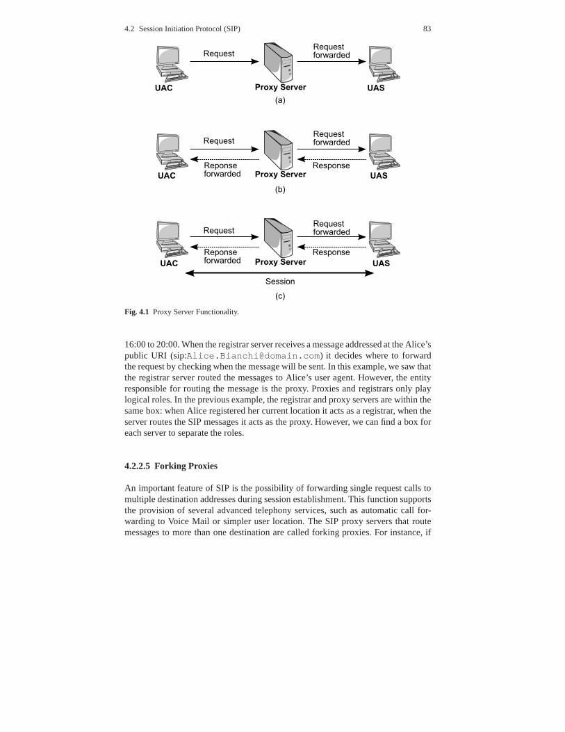
Proxy Servers are SIP routers. They receive a message and forward it to a user agentor another proxy along the path. The Proxy Server is the most important entity tounderstand how the SIP protocol routing works. A typical SIPsession is initiated bythe user agent client thanks to the services provided by the proxies. Users have theirUA configured to be directed to their respective proxy servers. The proxy serversthen communicate with each other to convey the message. If the proxy server isused, the caller UA sends an INVITE message to the proxy server. When the proxyserver determines a path to send the call and then forwards itFigure 4.1(a), the calleeresponds to the proxy server, which forwards the response tothe caller Figure 4.1(b).Once the proxy server forwards the acknowledgments of both parties, a session isthen established between the two clients Figure 4.1(c).
A proxy server can be also used for name mapping. A proxy server can ask alocation service and map an external SIP identity to an internal SIP identity. Theseproxy servers are not firewalls, they are independent servers on the Internet thatproxy the request on behalf of the user for various possible reasons. The ProxyServer can use an inter-organisational configuration through which SIP communi-cations are routed. This configuration is used when the messages are routed throughthe proxy servers before the messages are relayed to the destination SIP client. Thiscan be useful for internal communications where security over an Internet link canbe a problem.
4.2.2.4 Registrar
The Registrar server allows redirecting a call to where the client is usually reachable.This is possible by sending a request to change the address tothe registrar server.When the server receives these messages, it forwards the requests to the registeredaddress. For instance, a client (that we will call Alice) canbe reachable by twoaddresses:
• at home, where she has a computer - sip:[email protected]• and on her computer at the university laboratory - sip:[email protected].
edu
Alice registered both addresses with the registrar messageat domain.com. She wantsto receive the calls at the university between 9:00 and 13:30and at home from
4.2 Session Initiation Protocol (SIP) 83
Fig. 4.1 Proxy Server Functionality.
16:00 to 20:00. When the registrar server receives a messageaddressed at the Alice’spublic URI (sip:[email protected]) it decides where to forwardthe request by checking when the message will be sent. In thisexample, we saw thatthe registrar server routed the messages to Alice’s user agent. However, the entityresponsible for routing the message is the proxy. Proxies and registrars only playlogical roles. In the previous example, the registrar and proxy servers are within thesame box: when Alice registered her current location it actsas a registrar, when theserver routes the SIP messages it acts as the proxy. However,we can find a box foreach server to separate the roles.
4.2.2.5 Forking Proxies
An important feature of SIP is the possibility of forwardingsingle request calls tomultiple destination addresses during session establishment. This function supportsthe provision of several advanced telephony services, suchas automatic call for-warding to Voice Mail or simpler user location. The SIP proxyservers that routemessages to more than one destination are called forking proxies. For instance, if
84 4 Signalling
all the telephones ring at the same time in a house, the clienthas the time to pick upthe call in any rooms of the house. This is called parallel forking. A forking proxycan also route a message sequentially. For instance, if a client has two addresses, theserver can let a user agent ring for a certain time at the first location. If the clientdoes not pick up the call, the forking proxy forwards the callto the second address.
4.2.2.6 Redirect Server
The Redirect Server helps the UAC to find a new location of the receiver of themessage. When it receives a message, it contacts the location server to determine thepath to the callee and then sends a reply, which provides the client with informationabout the next hop (or hops) that the message should take. Thecaller then sends amessage directly to the device indicated in the redirectioninformation. Note that theredirect server does not forward the message to its destination as proxies do.
4.2.3 SIP Messages
As previously mentioned, SIP is based on HTTP, thus it is a textual request-responseprotocol. In order to establish a session, the clients send the requests and the serversanswer with responses. The format of SIP messages is composed by Start Line, anumber ofheader fields, anEmpty Lineand anOptional message body.
4.2.3.1 Start Line
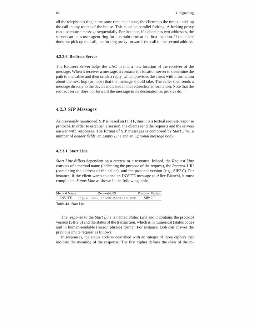
Start Linediffers dependent on arequestor a response. Indeed, theRequest Lineconsists of a method name (indicating the purpose of the request), theRequest-URI(containing the address of the callee), and the protocol version (e.g., SIP2.0). Forinstance, if the client wants to send an INVITE message to Alice Bianchi, it mustcompile theStatus Lineas shown in the following table.
Method Name Request-URI Protocol VersionINVITE sip:[email protected] SIP/ 2.0
Table 4.1 Start Line
Theresponseto theStart Lineis namedStatus Lineand it contains the protocolversion (SIP2.0) and the status of the transaction, which isin numerical (status code)and in human-readable (reason phrase) format. For instance, Bob can answer theprevious invite request as follows:
In responses, the status code is described with an integer ofthree ciphers thatindicate the meaning of the response. The first cipher definesthe class of the re-

4.2 Session Initiation Protocol (SIP) 85
Protocol Version Status Code Reason PhraseSIP/ 2.0 200 OK
Table 4.2 Invite Request
sponse and the others have no particular meaning. Some possible response classesare shown in the following table:
Status code Meaning1XX (100−199) Provisional: the request has been received
but at the server there is not definitiveresponse so it is continuing to process the request.
2XX (200−299) Success: the request has been successful3XX (300−399) Redirection: the callee has a new location4XX (400−499) Request Failure: the request has a syntax
error so the server does not understand the message5XX (500−599) Server Failure: the server does not implement
the request that appears to be good6XX (600−699) Global Failure: the request is not identified from any server
Table 4.3 Possible Responses for the example
4.2.3.2 Header Field
All messages have the mandatory header fields. In the SIP messages there are dif-ferent header fields. The most used are:
• To: contains the URI of the destination of the request. However, this addresscannot be definitive; in fact, as previously said, a client can change its location.In the presence of forking proxies, this field includes a tag value to distinguishamong the different user agents that are identified with the same URI.
• From: contains the URI of the caller. Like theTo header field it can specify a tagvalue.
• Call-ID: provides a unique identifier for a SIP message exchange.• Cseq: contains a number and a method name. They are used to match requests
and responses.• Contact: contains a list of addresses where the callee can find the caller.• Via: indicates the request’s path among proxies. The response uses this header
field to keep the same proxies traversed by the request. So it returns more quickly.• Max-Forwards: is used to avoid routing loops. Every proxy that handles a request
decrements its value by one, and if it reaches zero, the request is discarded.
Some header fields contain information on call services, addresses and protocolfeatures to establish a session, and a set of header fields provides information aboutthe message body, such as:

86 4 Signalling
• Content-Typeindicates which is the protocol used in the message body (in gen-eral it uses the SDP protocol).
• Content-Lengthcontains the length of the body expressed in bytes.
4.2.3.3 Message Body
The message body is separated from the header field by an emptyline. SIP mes-sages can carry any type of body, also multi-part bodies using MIME (MultipurposeInternet Mail Extensions) encoding. The MIME is a format that allows sending amessage with multiple attachments of different formats. For example, an e-mailmessage can carry a JPEG picture and an MPEG video. The most important aspectof the Message bodies is that they are transmitted end-to-end. In fact, the proxyserver does not need the message body to route the message. Note that the body canbe empty.
4.2.3.4 SIP Methods
SIP defines some several methods that are summarised in the following table:
Method name MeaningINVITE Establishes a session inviting a user to a callACK Confirms reliable message exchangesCANCEL Terminates a pending requestINFO Transports PSTN telephony signallingOPTIONS Solicits information about the capabilities
of the callee, but does not set up a call.REGISTER Conveys location information to a SIP server.
Allows a user to tell a SIP server how to map an incomingaddress into an outgoing address that will reach that user
BYE Terminates a sessionNOTIFY Notifies the user agent about a particular eventPRACK Acknowledges the reception of a provisional responsePUBLISH Uploads information to a serverSUBSCRIBE Requests to be notified about a particular eventUPDATE Modifies some characteristic of a sessionMESSAGE Carries an instant messageREFER Instructs a server to send a request
Table 4.4 SIP Methods
4.2 Session Initiation Protocol (SIP) 87
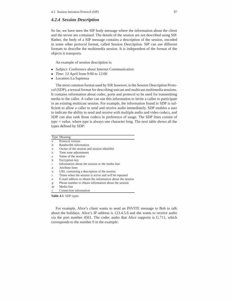
4.2.4 Session Description
So far, we have seen the SIP body message where the information about the clientand the server are contained. The details of the session are not described using SIP.Rather, the body of a SIP message contains a description of the session, encodedin some other protocol format, called Session Description.SIP can use differentformats to describe the multimedia session. It is independent of the format of theobjects it transports.
An example of session description is:
• Subject: Conference about Internet Communication• Time: 12 April from 9:00 to 12:00• Location:La Sapienza
The most common format used by SIP, however, is the Session Description Proto-col (SDP), a textual format for describing unicast and multicast multimedia sessions.It contains information about codec, ports and protocol to be used for transmittingmedia to the caller. A caller can use this information to invite a callee to participatein an existing multicast session. For example, the information found in SDP is suf-ficient to allow a caller to send and receive audio immediately. SDP enables a userto indicate the ability to send and receive with multiple audio and video codecs, andSDP can also rank those codecs in preference of usage. The SDPlines consist oftype = value, wheretypeis always one character long. The next table shows all thetypes defined by SDP:
Type Meaningv Protocol versionb Bandwidth informationo Owner of the session and session identifierz Time zone adjustmentss Name of the sessionk Encryption keyi Information about the session or the media linea Attribute linesu URL containing a description of the sessiont Times when the session is active and will be repeatede E-mail address to obtain the information about the sessionp Phone number to obtain information about the sessionm Media linec Connection information
Table 4.5 SDP types
For example, Alice’s client wants to send an INVITE message to Bob to talkabout the holidays. Alice’s IP address is 123.4.5.6 and she wants to receive audiovia the port number 4561. The codec audio that Alice supportsis G.711, whichcorresponds to the number 0 in the example:
88 4 Signalling
v =0o =Alice 2649376915 734564836585 IN IP4 123.4.5.6s =Talk about the next holidaysc =IN IP4 123.4.5.6t =0 0m=audio 4561 RTP/AVP 0a =sendrecvAs we can see in this example, an SDP description consists of two parts: session-
level information and media-level information. The first part (before the m-line)provides version and user identifiers (v-line and o-line), the subject of the session(s-line), Alice’s IP address (c-line) and the time of the session (t-line). Note that inthis case the session is supposed to take place at the moment this session is received,which is why the t-line is t = 0 0. The second part is stream-specific and consists ofan m-line and a number of optional a-lines that provide further information about themedia stream. The a-lines in the example indicates that the stream is bidirectional(user and server receive media).
4.2.5 Establishment of a SIP Session
SIP supports five ways of establishing and terminating multimedia sessions:
• User location: determination of the end system to be used for communication• User availability: determination of the willingness of the called party to engage
in communications• User capabilities: determination of the media and media parameters to be used• Session setup: ”ringing”, establishment of session parameters at both called and
calling party• Session management: including transfer and termination of sessions, modifying
session parameters, and invoking services
To establish a session the caller sends an INVITE message addressed to thecallee’s SIP URI, which he/she wants to contact. The INVITE message contains anumber of header fields that provide additional informationabout the message (thedestination address, the caller’s address, session information, etc.) and the sessiondescription. The session is established when the caller receives the OK response bythe callee. The 200 (OK) message contains a message body withthe SDP mediadescription of the type of the session that the callee is willing to establish with thecaller. As a result, there is a two-phase exchange of SDP messages - the first inthe request and the second in the response. This two-phase exchange provides basicnegotiation capabilities and is based on a simple request/response model of SDPexchange. Now that we have introduced the generic information about the sessionestablishment, let us give some examples of how SIP works.

4.2 Session Initiation Protocol (SIP) 89
4.2.5.1 Message Flow for Session Establishment
First of all, to establish a multimedia session, Alice must register her current loca-tion with the REGISTER message at thedomain.com by sending a REGISTERrequest, indicating that all messages addressed to the URI specified in theToheaderfield
must be forwarded to the URI specified in the CONTACT header field
The OK response by thedomain.com confirms that the request has been reg-istered. If Bob wants to contact Alice to talk about a meeting, he sends an INVITEmessage to Alice’s public URI. The proxy at thedomain.com routes the INVITErequest at Alice’s current location. Alice accepts the invitation by sending a200 OKresponse. The proxy at thedomain.com routes the200 OKmessage at the Bob’sURI.
Note that in the200 OKresponse Alice specifies her current location in the Con-tact header field. This header field is used by Bob to send subsequent messagesdirectly to Alice, bypassing the proxy server. As soon as thesession has been es-tablished, Bob and Alice can talk about whatever they want. If, in the middle of thesession, they want to make any changes to the session (e.g., add video), they shouldissue another INVITE request with an updated session description.
When Bob and Alice finish their conversation, Bob sends a BYE request directlyto Alice without interaction with the proxy. Alice confirms the request with an OKresponse. Session description is summarised in Figure 4.2.
Fig. 4.2 Session Description.

90 4 Signalling
4.2.5.2 Home Phone
One of the most interesting technical challenges for IP telephony is to mimic stan-dard residential phone services. In particular, IP telephony requires the followingfeatures:
• All phones in a home must ring if someone calls its number.• When one of the lines is picked up, all other phones in the homemust stop ring-
ing.• A user can join an existing call by picking up any other telephone in the home.• A home can have multiple lines, enabling a user on another handset to initiate a
new call while one or more are in progress.• All users involved in a single call are essentially involvedin a multi-party con-
ference call, and are thus able to hear each other.
A simple example further explains these features: Alice sends an invite messageto Bob’s parents. When the network server receives the message, it consults thedatabase to find the list of contact addresses, each of which constitutes a singleextension of the line. The server thus forks and sends out theINVITE messages at allmembers of the family and the lines ring at each address. Whena user picks up thecall (Member 3), an acceptance message is sent back to the server. When a forkingproxy receives a call acceptance, it should send a cancel request on all unansweredmembers of the family (Member 1 and Member 2). Then, the server forwards thecall acceptance. After that, if another callee picks up the call, an acceptance messageis acknowledged by the server and the new participants join the call. To terminatethe session, the caller sends a BYE message that is forwardedby the proxy to thetwo currently active lines.
4.2.5.3 Personal Mobility
Alice is a university researcher. So, in addition to having acomputer at home(sip: [email protected]), she also has two location addresses atthe university, at the laboratory (sip:[email protected]) and at the office(sip: [email protected]). When Alice is at the university, she sends aREGISTER message to thedomain.com server listing the university address (sip:[email protected]) as a forwarding address. Once at the university, Alice regis-ters both her lab and office machine with the registration server of the university.Now, if someone sends a request to Alice’s public URL (sip:[email protected]), thedomain.com server checks the current location of Alice inthe database and forwards the request to the university server. As soon as the re-quest arrives, the university server looks up the database and determines that Alicehas two potential means of contact. The server then forks andsends the request toboth the lab and office machines at the same time, causing the ringing of the phones.When Alice picks up the call, an acceptance message is sent back to the server andthe session is established, as we have seen above. We have a different situation if Al-

4.3 The Next Steps In Signalling (NSIS) 91
ice forgets to register the lab machine, for instance, and restarts her user agent in thelab to forward the call to herdomain.com server. When the lab phone receives therequest, according to its outdated configuration, it forwards it to thedomain.comserver. Using the loop detection capabilities in SIP, this server determines that anerror has occurred and returns an error response to the lab machine. In turn, it re-turns an error code to the university server. If, in the meantime, Alice responds tothe call from the office, the university server also receivesan acceptance message.Having now received both responses, the server forwards theacceptance answerestablishing a session.
4.2.6 SIP’s Extension
SIP’s extension negotiation mechanism uses three header fields: Supported, Re-quired, and Unsupported. When a SIP session is being established, the user agentclient lists in the Required header field all the names of the extensions it wants to usefor that session, and all the names of the extensions it supports are not listed previ-ously in aSupportedheader field. When the user agent server receives theRequiredheader field, it checks the list and, if it does not support anyof the extensions listed,it sends back an error message specifying that the session could not be established.This error response contains anUnsupportedheader field listing the extensions theuser agent server did not support. If the user agent server supports all the requiredextensions, it should decide whether or not it wants to use any extra extensions and,if so, it includes the option tag for the extension in theRequiredheader of its re-sponse. If this option was included in theSupportedheader field of the request, thesession will be established. Otherwise, the user agent server includes the extensionthat is required by the server in aRequiredheader field in the error response.
4.3 The Next Steps In Signalling (NSIS)
4.3.1 Background and main Characteristics
The IETF’s Next Steps in Signalling Working Group is responsible for standardis-ing an IP signalling protocol with QoS signalling as the firstuse case. This workinggroup will concentrate on a two-layer signalling paradigm.The intention is to re-use, where appropriate, the protocol mechanisms of RSVP, while at the same timesimplifying it and applying a more general signalling model. The existing work onthe requirements, the framework and analysis of existing protocols will be com-pleted and used as input for the protocol work. The NSIS WG is developing a trans-port layer signalling protocol for the transport of upper layer signalling. In orderto support a toolbox or building block approach, the two-layer model will be used
92 4 Signalling
to separate the transport of the signalling from the application signalling. This al-lows for a more general signalling protocol to be developed to support signalling fordifferent services or resources, such as NAT, firewall traversal, and QoS resources.The initial NSIS application will be an optimised RSVP QoS signalling protocol.The second application will be a middle box traversal protocol. Security is a veryimportant point for NSIS and the working group will study andanalyse the threatsand security requirements for signalling. Compatibility with authentication and au-thorisation mechanisms such as Diameter, COPS for RSVP (RFC2749) and RSVPSessions will be addressed. NSIS is a signalling protocol framework for convey-ing information about data flows along their path in the network, and interactingwith nodes along the data path. Moreover, the NSIS messages pass directly throughthe same nodes as the data and only unicast data flows are considered. The inten-tion is that the components of the NSIS protocol suite will beusable in differentparts of the Internet, for different needs, without requiring a complete end-to-enddeployment (signalling is intended not only for QoS). This flexibility is achieved bydividing the signalling protocol stack in two layers: a generic (lower) layer and anupper layer specific for each signalling application.
4.3.2 Background and Main Characteristics
In the signalling architecture, the messages are only received, processed and sentby Signalling Entities (SE) that can be placed on all deviceson the data path (tosupport signalling purposes) or on some devices not included on the data path. Twodifferent signalling architectures can be realised (distributed and centralised) andwill be analysed in the following sections. In the distributed signalling architec-ture, SEs are placed on all devices (e.g., routers) on the data path. Thus, all devicesare signalling-aware and take part in signalling. In the centralised signalling archi-tecture, signalling is managed by a centralised SE in a domain. This architecturereduces the signalling charge on the interior devices in thedomain.
4.3.2.1 Signalling Entities (SE)
A Signalling Entity (SE) is the function that implements thesignalling protocol. Itcan be placed in a network device (e.g., router, policy server) or in end systems.SE can support many signalling applications (for instance resource reservation).A Signalling Initiator (SI) is the SE that initiates the signalling, while SignallingResponder (SR) is the SE that is at the end of the signalling path and terminates thesignalling. Signalling Forwarder (SF) is a SE that is on the signalling path betweenSI and SR. SF receives, processes and forwards signalling messages from SI toSR. Finally, Signalling Controller (SC) is the centralisedSE in a domain. A SC isresponsible for receiving, processing and sending signalling messages in a domain
4.3 The Next Steps In Signalling (NSIS) 93
and it is used in the centralised signalling architecture toreduce the charge on theedge routers and interior routers.
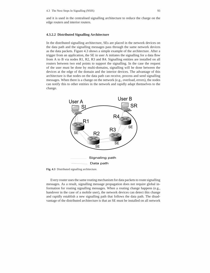
4.3.2.2 Distributed Signalling Architecture
In the distributed signalling architecture, SEs are placedin the network devices onthe data path and the signalling messages pass through the same network devicesas the data packets. Figure 4.3 shows a simple example of the architecture. After atrigger from an application, the SE in user A initiates the signalling for a data flowfrom A to B via nodes R1, R2, R3 and R4. Signalling entities areinstalled on allrouters between two end points to support the signalling. Inthe case the requestof the user must be done by multi-domains, signalling will bedone between thedevices at the edge of the domain and the interior devices. The advantage of thisarchitecture is that nodes on the data path can receive, process and send signallingmessages. When there is a change on the network (e.g., overload, errors), the nodescan notify this to other entities in the network and rapidly adapt themselves to thechange.
Fig. 4.3 Distributed signalling architecture.
Every router uses the same routing mechanism for data packets to route signallingmessages. As a result, signalling message propagation doesnot require global in-formation for routing signalling messages. When a routing change happens (e.g.,handover in the case of a mobile user), the network devices can detect this changeand rapidly establish a new signalling path that follows thedata path. The disad-vantage of the distributed architecture is that an SE must beinstalled on all network
94 4 Signalling
devices on the data path with consequently increased load ofsignalling on the inter-mediate nodes between two end points. Moreover, when the number of user flowsincreases, the information of state per flow contained in intermediate nodes can alsoincrease. This could cause serious scalability problems.
4.3.2.3 Centralised Signalling Architecture
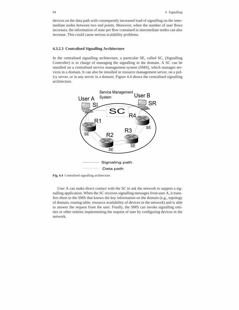
In the centralised signalling architecture, a particular SE, called SC, (SignallingController) is in charge of managing the signalling in the domain. A SC can beinstalled on a centralised service management system (SMS), which manages ser-vices in a domain. It can also be installed in resource management server, on a pol-icy server, or in any server in a domain. Figure 4.4 shows the centralised signallingarchitecture.
Fig. 4.4 Centralised signalling architecture.
User A can make direct contact with the SC to ask the network tosupport a sig-nalling application. When the SC receives signalling messages from user A, it trans-fers them to the SMS that knows the key information on the domain (e.g., topologyof domain, routing table, resource availability of devicesin the network) and is ableto answer the request from the user. Finally, the SMS can invoke signalling enti-ties or other entities implementing the request of user by configuring devices in thenetwork.

4.3 The Next Steps In Signalling (NSIS) 95
4.3.3 Overview of Signalling Scenarios and Protocol Structure
4.3.3.1 Layer Model for the Protocol Suite
In order to achieve a modular solution for the NSIS requirements, the NSIS WGproposed a split-layer protocol suite structured in two layers:
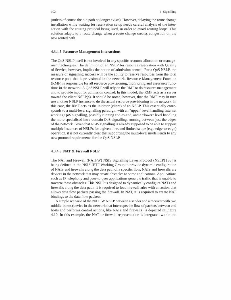
The NSIS Transport Layer Protocol, named General Internet Signaling Transport(GIST) [Schulzrinne2006], is responsible for moving signalling messages amongnetwork entities. This process should be independent of thesignalling applications.The NSLP (NSIS Signalling Layer Protocol contains the specific functionalities ofthe signalling applications. As described in the followingsubsection, this two-layerprotocol model allows the support of various signalling applications, such as QoS[Manner2006] and Network Address Translation (NAT) & Firewall (FW) [Stiemer-ling2006] (see Figure 4.5.
Fig. 4.5 Protocol Signalling Architecture.
4.3.3.2 Signalling Application Properties
For some signalling applications and scenarios, signalling may only be consideredfor a uni-directional data flow. However, in other cases there may be interestingrelationships between the signalling for the two flows of a bi-directional session.An example is QoS for a voice call. Note that the path may be different for two
96 4 Signalling
directions, due to asymmetric routing. In the basic case, bi-directional signallingcan simply use a separate instance of the same signalling mechanism in each di-rection. In constrained topologies where parts of the routeare symmetric, it maybe possible to use a more unified approach to bidirectional signalling, e.g. carry-ing the two signalling directions in common messages. This optimisation might beused for example to make mobile QoS signalling more efficient. In either case, thecorrelation of the signalling for the two flow directions is carried out in the NSLP.The NTLP would simply be enabled to bundle the messages together. Moreover,to provide additional flexibility in defining the objects carried by the NSLP suchthat only the objects applicable in a particular setting areused. One approach forreflecting the distinction is that local objects could be putinto separate local mes-sages that are initiated and terminated within one single domain; an alternative isthat they could be ”stacked” within the NSLP messages that are used anyway forinter-domain signalling. We are assuming that the NTLP provides a simple messagetransfer service, and any acknowledgments or notificationsit generates are handledpurely internally (and applied within the scope of a single NTLP peer relationship).However, we expect that some signalling applications will require acknowledgmentsregarding the failure/success of state installation alongthe data path, and this will bean NSLP function. Acknowledgments can be sent along the sequence of NTLP peerrelationships toward the signalling initiator, which relieves the requirements on thesecurity associations that need to be maintained by NEs and can allow NAT traversalin both directions (if this direction is toward the sender, it implies maintaining re-verse routing state in the NTLP). In certain circumstances,e.g. trusted domains, anoptimisation could be to send acknowledgments directly to the signalling initiatoroutside the NTLP, although any such approach would have to take into account thenecessity of handling denial of service attacks launched from outside the network.The semantics of the acknowledgment messages are of particular importance. ANE sending a message could assume responsibility for the entire downstream chainof NEs, indicating for instance the availability of reserved resources for the entiredownstream path. Alternatively, the message could have a more local meaning, indi-cating for instance that a certain failure or degradation occurred at a particular pointin the network. Notifications differ from acknowledgments,because they are not(necessarily) generated in response to other signalling messages. This means that itmay not be obvious to determine where the notification shouldbe sent.
4.3.4 The NSIS Layer Transport Protocol
4.3.4.1 GIST Description
The GIST layer is responsible for the transport of signalling messages. When asignalling message is ready to be sent, it is given to the GISTlayer along withinformation about the flow it is for; it is then up to the GIST layer to get the messageto the next network element (NE) along the path (downstream,in the flow direction
4.3 The Next Steps In Signalling (NSIS) 97
from the source to the destination; or upstream, in the opposite direction of theflow from the destination to the source), where it is receivedand the local GISTresponsibility ends.
In the receiving NE, the GIST either forwards the message directly to the nexthop or, if there is an appropriate signalling application, passes it upwards for furtherprocessing; the signalling application can then generate another message to be sentvia GIST.
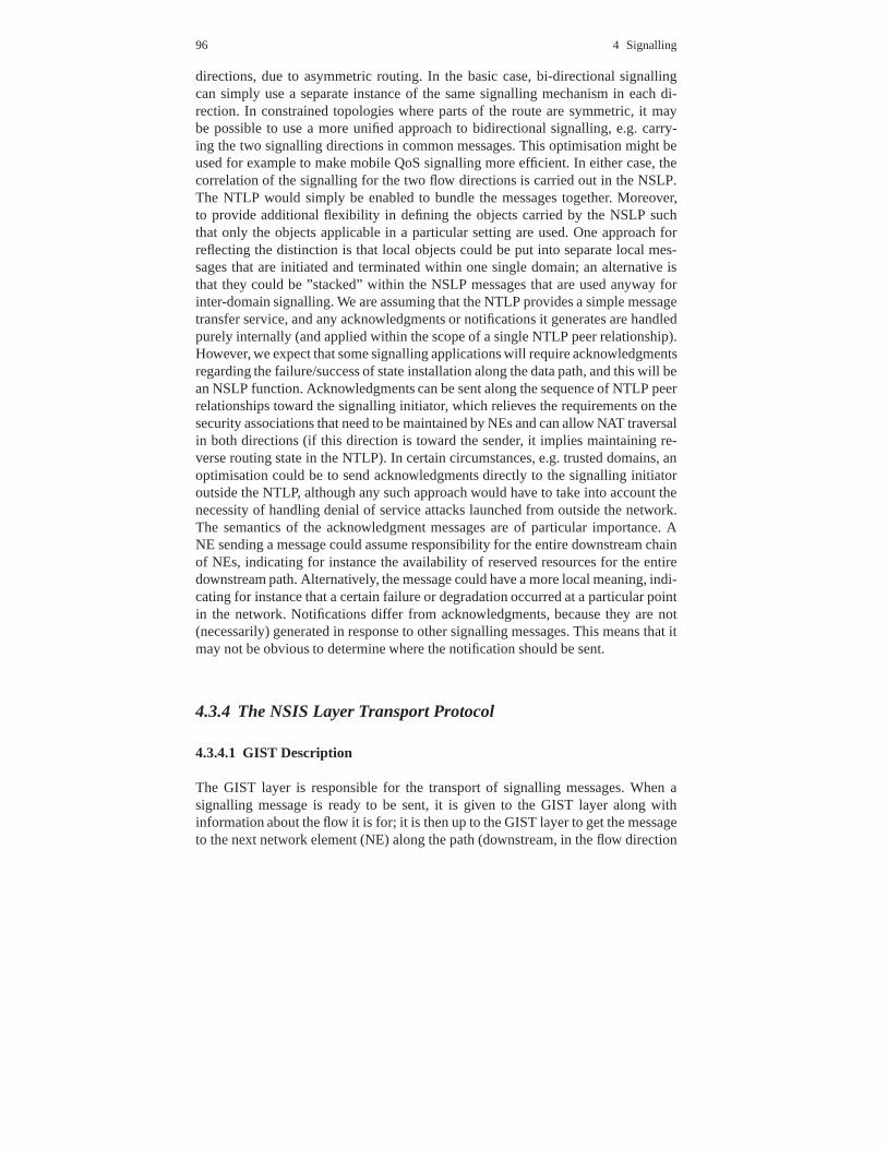
Figure 4.6. is an example of the NSIS two-layer architecture, showing two differ-ent signalling applications and how NEs handle the signalling messages accordingly.
Fig. 4.6 Signalling with Heterogeneous NSLPs.
In this example, the first NE in the path has the NTLP and NSLP 1.NSLP 1generates a signalling message and sends it to the local NTLPso that it can be for-warded to the flow destination. In the next NE, there are no NSLPs, so the messageis forwarded without being processed by the NTLP. In the nexthop the NTLP andNSLP 2 are present. Since the message NSLP ID does not correspond to the con-nected NSLP 2, the message is forwarded to the flow destination again. In the nexthop there is again NTLP and NSLP 1. Since the correct NSLP is available, NTLPsends the message to NSLP 1. When NSLP receives the message from NTLP, itprocesses it accordingly.
GIST allows two modes of operation, the Datagram mode (D-mode) and theConnection mode (C-mode). D-mode uses UDP to encapsulate the messages andis used for small and infrequent messages. All Query messages must be sent inD-mode. The C-mode uses TCP or any other stream or message oriented transportprotocol (currently only Stream Control Transmission Protocol, SCTP [83], is beingresearched in addition to TCP) which allows GIST to support reliability and security(for example using Transport Layer Security, TLS, [84] overTCP) in the messagetransport.
To meet the routing requirement, GIST defines a 3-way handshake to set upthe necessary connection with the adjacent peers. This 3-way handshake contains

98 4 Signalling
a QUERY, a RESPONSE and an optional CONFIRM message. Figure 4.7 describesthe 3-way handshake process between two entities that support GIST. In this hand-shake, the QUERY message is the first message to be sent. This message is alwayssent in D-mode and with the IP Router Alert Option (RAO) [85] flag active. Withthis flag, the message sent by GIST travels along the network and every router thatchecks this flag analyses the packet content. GIST entities in the network analyseall packets flagged with the IP RAO and process all QUERY messages.
Fig. 4.7 GIST 3-way handshake.
When a QUERY message is intercepted, the NSLP ID is checked and if the cor-responding NSLP is present, the message is processed by GIST. Otherwise, the mes-sage is forwarded to the flow destination so that other GIST entities can interceptthe message, or the destination is reached.
The purpose of the QUERY message is the discovery of the next NSIS hop inthe path and the transport of a proposal for the establishment of a connection be-tween the two entities. These messages contain a QUERY Cookie object and whena connection is requested, the association characteristics (for instance the protocoland port to use in the association) are also present. The QUERY Cookie is a secu-rity payload that is carried by the QUERY message, which allows the detection andprevention of several security problems in the handshake.
GIST entities that receive a QUERY message need to reply witha RESPONSEmessage. This message is sent to the previous GIST entity by getting its identity

4.3 The Next Steps In Signalling (NSIS) 99
from the QUERY message. This message contains a RESPONSE Cookie, which is acryptographic key based on the received QUERY Cookie. This RESPONSE Cookieincreases the security of the protocol, allowing the upstream hop to check if theResponse message is not sent by a fake NSIS entity. If the received QUERY messagerequested an association, the RESPONSE message also includes the associationresponse.
If the association between the two GIST entities is requested (by the NSLP orby a local GIST decision/configuration) when the RESPONSE message is receivedin the upstream GIST, the association is created and a CONFIRM message is sentto the downstream GIST using the association. This association can be supportedthrough TCP, secure TCP with Transport Layer Security (TCP/TLS) or the StreamControl Transmission Protocol (SCTP). Only after the CONFIRM message is sent,the NSLPs payloads can start flowing between the two GISTs.
The associations created via the 3-way handshake can be re-used for differentsessions and NSLPs when the downstream peer and the association characteristicsare the same. Even though the 3-way handshake is needed for each new session,the RESPONSE and CONFIRM messages are sent using the alreadyestablishedassociation.
GIST was designed as a soft-state protocol to manage all the messages and as-sociations. GIST uses states for each action occurred in thesystem and associates atimer to each state. Each time the state is updated, the timeris restarted. If the stateis not updated, the timer expires and the state is removed. GIST has two main statetables: Message Routing State (MRS) and Message Association State (MAS). TheMRS is responsible for managing individual flows and the MAS is responsible formanaging the associations between individual peers. When atimer expires (if nomessage is received for the corresponding flow or association), the state automati-cally is removed from the state tables. If a state is requiredagain, a new handshakeis needed and a new association must be created.
After the handshake is completed, data messages can be sent with the NSLPpayload. GIST does not check the NSLP payload, the only processing done to themessage is the decrement of the message hop-count, the corresponding states arerefreshed (MRS and MAS) and finally the payload is sent to the correspondingNSLP.
QoS NSLP is described in the following subsection. This NSLPis one exampleof an NSLP that uses GIST as its transport protocol.
4.3.4.2 Signalling for Quality of Service
In the case of signalling for QoS, we can apply all the basic NSIS concepts. Inaddition, there is an assumed directionality of the signalling process in that one endof the signalling flow takes responsibility for actually requesting the resources. Thisleads to the following definitions:
• The protocol employs a client/server model where the PEP requests, updates anddeletes to the remote PDP and the PDP returns decisions back to the PEP.

100 4 Signalling
• QoS NSIS Responder (QNR): the signalling entity that acts asthe endpoint forthe signalling and can optionally interact with applications as well.
• QoS NSIS Forwarder (QNF): a signalling entity between a QNI and QNR, whichpropagates NSIS signalling further through the network.
• COPS provides message level security for authentication, replay protection andmessage integrity. COPS can also reuse existing protocol for security (IPSEC) orto authenticate and secure the channel between the PEP and the PDP.
Each of these entities will interact with a resource management function (RMF),which actually allocates network resources (router buffers, interface bandwidth,etc.). Note that there is no constraint on which end of the signalling flow shouldtake the QNI role: with respect to the data flow direction it could be at the sendingor receiving end.
4.3.4.3 Protocol Message Semantics
The QoS NSLP will include a set of messages to reserve resources along the sig-nalling path. A possible set of message semantics for the QoSNSLP is shown below.Note that the ”direction” column in the table below only indicates the ”orientation”of the message. Messages can be originated and absorbed at QNF nodes as well asthe QNI or QNR. An example might be QNFs at the edge of a domain exchangingmessages to set up resources for a flow across it. Note that it is left open whetherthe responder can release or modify a reservation, during orafter setup. This seemsmainly a matter of assumptions about authorisation, and thepossibilities might de-pend on resource type specifics. The table also explicitly includes a refresh opera-tion. This does nothing to a reservation except extend its lifetime, and is one possiblestate management mechanism.
Operation Direction DescriptionRequest I to R Create a new reservation for a flowModify I to R Modify an existing reservation
(R to I)Release I to R Delete (tear down) an existing reservation
(R to I)Accept/Reject R to I Confirm or reject a reservation requestNotify I to R Report an event detected within the network
(R to I)Refresh I to R State Management
Table 4.6 NSIS Protocol Messages
4.3 The Next Steps In Signalling (NSIS) 101
4.3.4.4 Route Changes and QoS Reservations
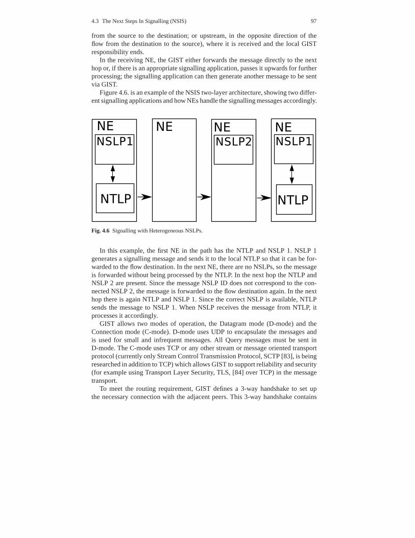
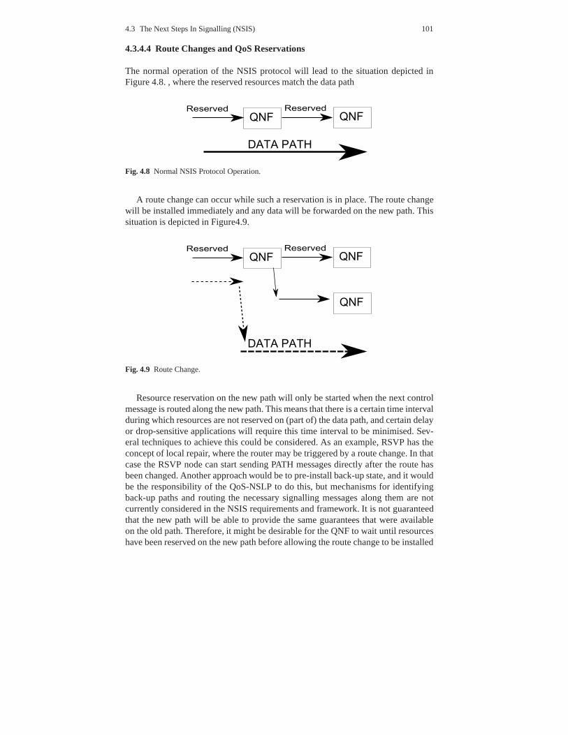
The normal operation of the NSIS protocol will lead to the situation depicted inFigure 4.8. , where the reserved resources match the data path
Fig. 4.8 Normal NSIS Protocol Operation.
A route change can occur while such a reservation is in place.The route changewill be installed immediately and any data will be forwardedon the new path. Thissituation is depicted in Figure4.9.
Fig. 4.9 Route Change.
Resource reservation on the new path will only be started when the next controlmessage is routed along the new path. This means that there isa certain time intervalduring which resources are not reserved on (part of) the datapath, and certain delayor drop-sensitive applications will require this time interval to be minimised. Sev-eral techniques to achieve this could be considered. As an example, RSVP has theconcept of local repair, where the router may be triggered bya route change. In thatcase the RSVP node can start sending PATH messages directly after the route hasbeen changed. Another approach would be to pre-install back-up state, and it wouldbe the responsibility of the QoS-NSLP to do this, but mechanisms for identifyingback-up paths and routing the necessary signalling messages along them are notcurrently considered in the NSIS requirements and framework. It is not guaranteedthat the new path will be able to provide the same guarantees that were availableon the old path. Therefore, it might be desirable for the QNF to wait until resourceshave been reserved on the new path before allowing the route change to be installed
102 4 Signalling
(unless of course the old path no longer exists). However, delaying the route changeinstallation while waiting for reservation setup needs careful analysis of the inter-action with the routing protocol being used, in order to avoid routing loops. Thissolution adapts to a route change when a route change createscongestion on thenew routed path.
4.3.4.5 Resource Management Interactions
The QoS NSLP itself is not involved in any specific resource allocation or manage-ment techniques. The definition of an NSLP for resource reservation with Qualityof Service, however, implies the notion of admission control. For a QoS NSLP, themeasure of signalling success will be the ability to reserveresources from the totalresource pool that is provisioned in the network. Resource Management Function(RMF) is responsible for all resource provisioning, monitoring and assurance func-tions in the network. A QoS NSLP will rely on the RMF to do resource managementand to provide input for admission control. In this model, the RMF acts as a servertoward the client NSLP(s). It should be noted, however, thatthe RMF may in turnuse another NSLP instance to do the actual resource provisioning in the network. Inthis case, the RMF acts as the initiator (client) of an NSLP. This essentially corre-sponds to a multi-level signalling paradigm with an ”upper”level handling Internetworking QoS signalling, possibly running end-to-end, and a”lower” level handlingthe more specialised intra-domain QoS signalling, runningbetween just the edgesof the network. Given that NSIS signalling is already supposed to be able to supportmultiple instances of NSLPs for a given flow, and limited scope (e.g., edge-to-edge)operation, it is not currently clear that supporting the multi-level model leads to anynew protocol requirements for the QoS NSLP.
4.3.4.6 NAT & Firewall NSLP
The NAT and Firewall (NATFW) NSIS Signalling Layer Protocol(NSLP) [86] isbeing defined in the NSIS IETF Working Group to provide dynamic configurationof NATs and firewalls along the data path of a specific flow. NATsand firewalls aredevices in the network that may create obstacles to some applications. Applicationssuch as IP telephony and peer-to-peer applications generate traffic that is unable totraverse these obstacles. This NSLP is designed to dynamically configure NATs andfirewalls along the data path. It is required to load firewall rules with an action thatallows data flow packets passing the firewall. In NAT, it is required to create NATbindings to the data flow packets.
A simple scenario of the NATFW NSLP between a sender and a receiver with twomiddle-boxes (device in the network that intercepts the flowof packets between endhosts and performs control actions, like NATs and firewalls)is depicted in Figure4.10. In this example, the NAT or firewall representation is integrated within the
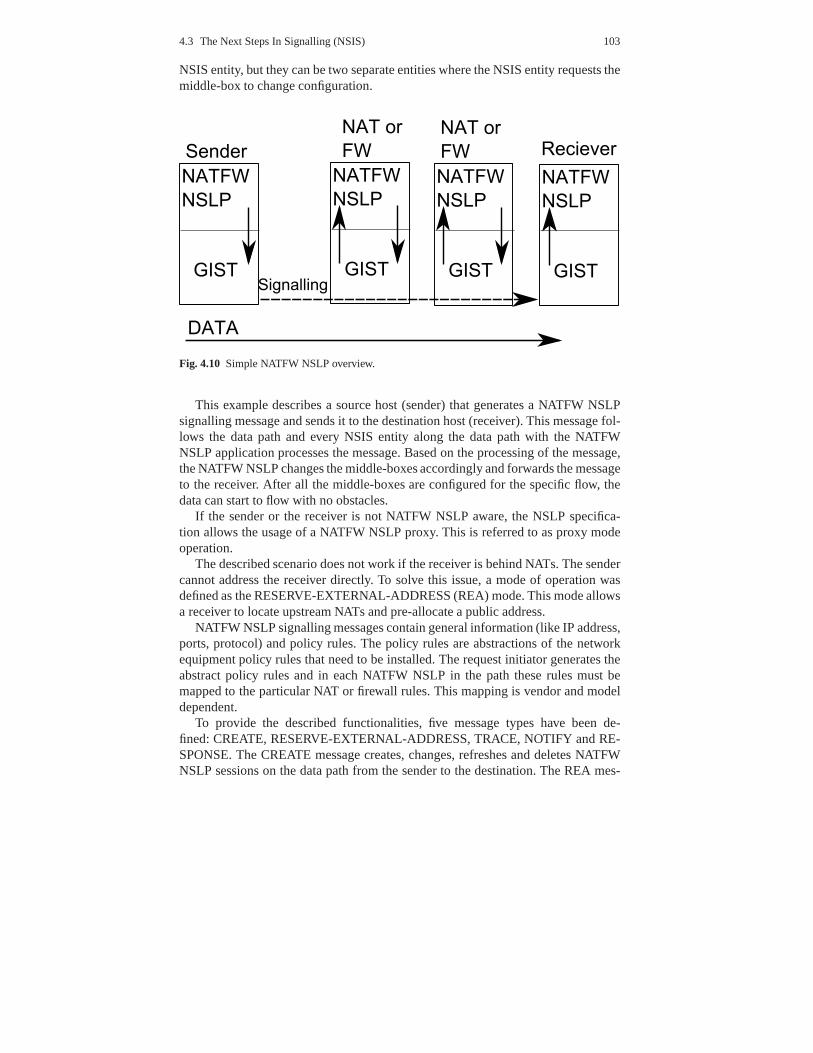
4.3 The Next Steps In Signalling (NSIS) 103
NSIS entity, but they can be two separate entities where the NSIS entity requests themiddle-box to change configuration.
Fig. 4.10 Simple NATFW NSLP overview.
This example describes a source host (sender) that generates a NATFW NSLPsignalling message and sends it to the destination host (receiver). This message fol-lows the data path and every NSIS entity along the data path with the NATFWNSLP application processes the message. Based on the processing of the message,the NATFW NSLP changes the middle-boxes accordingly and forwards the messageto the receiver. After all the middle-boxes are configured for the specific flow, thedata can start to flow with no obstacles.
If the sender or the receiver is not NATFW NSLP aware, the NSLPspecifica-tion allows the usage of a NATFW NSLP proxy. This is referred to as proxy modeoperation.
The described scenario does not work if the receiver is behind NATs. The sendercannot address the receiver directly. To solve this issue, amode of operation wasdefined as the RESERVE-EXTERNAL-ADDRESS (REA) mode. This mode allowsa receiver to locate upstream NATs and pre-allocate a publicaddress.
NATFW NSLP signalling messages contain general information (like IP address,ports, protocol) and policy rules. The policy rules are abstractions of the networkequipment policy rules that need to be installed. The request initiator generates theabstract policy rules and in each NATFW NSLP in the path theserules must bemapped to the particular NAT or firewall rules. This mapping is vendor and modeldependent.
To provide the described functionalities, five message types have been de-fined: CREATE, RESERVE-EXTERNAL-ADDRESS, TRACE, NOTIFY and RE-SPONSE. The CREATE message creates, changes, refreshes anddeletes NATFWNSLP sessions on the data path from the sender to the destination. The REA mes-
104 4 Signalling
sage is forwarded from the receiver to the edge NAT to allow inbound CREATEmessages to be forwarded to the receiver. This message reserves an external address(and a port number if needed) in the edge router and requests the configuration of allintermediate middle-boxes (between the receiver and the edge NAT). The TRACEmessage gathers information from all NATFW NSLP in the data path. The NOTIFYmessage is an asynchronous message used by the NSLP to notifyupstream peersabout specific events. The RESPONSE message is a response to CREATE, REAand TRACE messages.
All messages received by a NATFW NSLP before being processedare checkedas to whether the requested actions are authenticated and authorised. For this pur-pose all the NATFW NSLP messages carry the NATFW CREDENTIAL object. Theinformation and structure of this object depends on the authentication and authori-sation model used in each domain.
4.4 Common Open Policy Service (COPS)
4.4.1 COPS Overview
COPS (Common Open Policy Service specified in the RFC 2748 [87] is a sim-ple query and response protocol that can be used to exchange policy informationbetween a policy server (Policy Decision Point or PDP) and its clients (Policy En-forcement Points or PEPs). COPS supports two models of policy control: outsourc-ing and configuration (also known as provisioning). In the outsourcing model thePEP contacts the PDP every time a policy decision has to be made. The PDP makesthe decision and communicates it back to the PEP, which enforces it. In the con-figuration model the PDP configures the PEP with the policy to be used. The PEPstores the policy received from the PDP locally and uses it tomake decisions insteadof contacting the PDP every time a new event occurs. The main characteristics ofCOPS protocol include:
• The protocol employs a client/server model where the PEP requests, updates anddeletes to the remote PDP and the PDP returns decisions back to the PEP.
• The protocol uses TCP (Transfer Control Protocol) as its transport protocol forreliable exchange of messages between policy clients and a server.
• The protocol is extensible in that it is designed to leverageoff self-identifying ob-jects and can support diverse client specific information without requiring modi-fications to the COPS protocol itself.
• COPS provides message level security for authentication, replay protection andmessage integrity. COPS can also reuse existing protocol for security (IPSEC) orto authenticate and secure the channel between the PEP and the PDP.
• The protocol allows the server to push configuration information to the client,and than allows the server to remove such state from the client when it is nolonger applicable.
4.4 Common Open Policy Service (COPS) 105
• The protocol is stateful in two main aspects:
– TheRequest/Decisionstate is shared between client and server. The requestsfrom the client PEP are installed or remembered by the remotePDP until theyare explicitly deleted by the PEP. At the same time, decisions from the remotePDP can be generate asynchronously at any time for a currently installed re-quest state.
– In theInter-associatedstate, the server may respond to new queries differentlybecause of previously installedRequest/Decisionstate(s) that are related.
4.4.2 Basic Model
The basic model of COPS and the framework of policy-based admission control areshown in the Figure 4.11. The network nodes can be routers, switches or hubs. Theresources are allocated or released inside a node by PEP (Policy Enforcement Point).A node can be a policy ignorant node, which does not support the COPS protocol.The network nodes are grouped into administrative domains.There is always at leastone policy server in each administrative domain. Inside thepolicy server there is thePDP (Policy Decision Point), which makes the final decision about the handling ofthe resources. There can also be a local PDP in the network node (see Figure 4.11.).
The PEP may communicate with a policy server to obtain policydecisions ordirectives. It is responsible for initiating a persistent TCP connection to a PDP, fornotifying the PDP when a request state has changed on the PEP and, finally, for thedeletion of any state that is no longer applicable. When the PEP sends a configura-tion request, it expects the PDP to continuously send the named units of configu-ration data until it is successfully installed, and then thePEP should send a reportmessage to the PDP confirming the installation. The policy protocol is designed tocommunicate self-identifying objects that contain the data necessary for identifyingrequest states, establishing the context for a request, identifying the type of the re-quest, referencing previously installed request, relaying policy decisions, reportingerrors and providing message integrity. When a failure is detected, the PEP must tryto reconnect to the remote PDP or attempt to connect to a backupalternative PDP.While disconnected, the PEP should revert to making local decision with LPDP;once the connection is re-established, the PEP is expected to notify the PDP of anydeleted state or new event that passed local admission control after the connectionwas lost. The PDP can also send unsolicited decisions to the PEP, e.g., the PDP canforce the PEP to change previous decisions. Respectively, the PDP can send infor-mation for accounting or monitoring purposes to the PDP. ThePEP outsources thedecision making to the PDP. Although the PEP can make local decisions with theLPDP, the final decision is made by the remote PDP. There are three different typesof outsourcing events that need the decision from the PDP andone not outsourcingtype (Figure 4.12. ). These define the context of the each request and decision. The
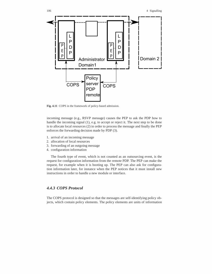
106 4 Signalling
Fig. 4.11 COPS in the framework of policy-based admission.
incoming message (e.g., RSVP message) causes the PEP to ask the PDP how tohandle the incoming signal (1), e.g. to accept or reject it. The next step to be doneis to allocate local resources (2) in order to process the message and finally the PEPenforces the forwarding decision made by PDP (3).
1. arrival of an incoming message2. allocation of local resources3. forwarding of an outgoing message4. configuration information
The fourth type of event, which is not counted as an outsourcing event, is therequest for configuration information from the remote PDP. The PEP can make therequest, for example when it is booting up. The PEP can also ask for configura-tion information later, for instance when the PEP notices that it must install newinstructions in order to handle a new module or interface.
4.4.3 COPS Protocol
The COPS protocol is designed so that the messages are self-identifying policy ob-jects, which contain policy elements. The policy elements are units of information
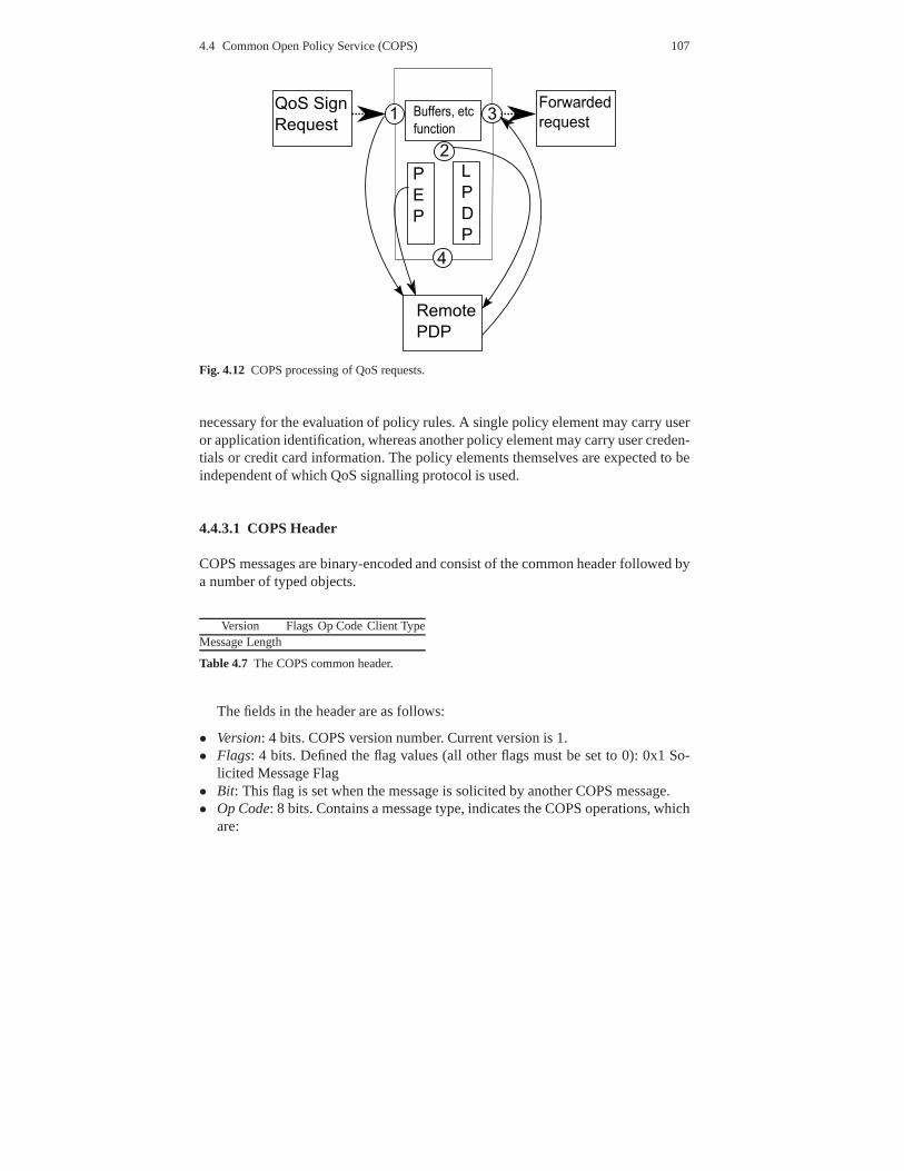
4.4 Common Open Policy Service (COPS) 107
Fig. 4.12 COPS processing of QoS requests.
necessary for the evaluation of policy rules. A single policy element may carry useror application identification, whereas another policy element may carry user creden-tials or credit card information. The policy elements themselves are expected to beindependent of which QoS signalling protocol is used.
4.4.3.1 COPS Header
COPS messages are binary-encoded and consist of the common header followed bya number of typed objects.
Version Flags Op Code Client TypeMessage Length
Table 4.7 The COPS common header.
The fields in the header are as follows:
• Version: 4 bits. COPS version number. Current version is 1.• Flags: 4 bits. Defined the flag values (all other flags must be set to 0): 0x1 So-
licited Message Flag• Bit: This flag is set when the message is solicited by another COPSmessage.• Op Code: 8 bits. Contains a message type, indicates the COPS operations, which
are:
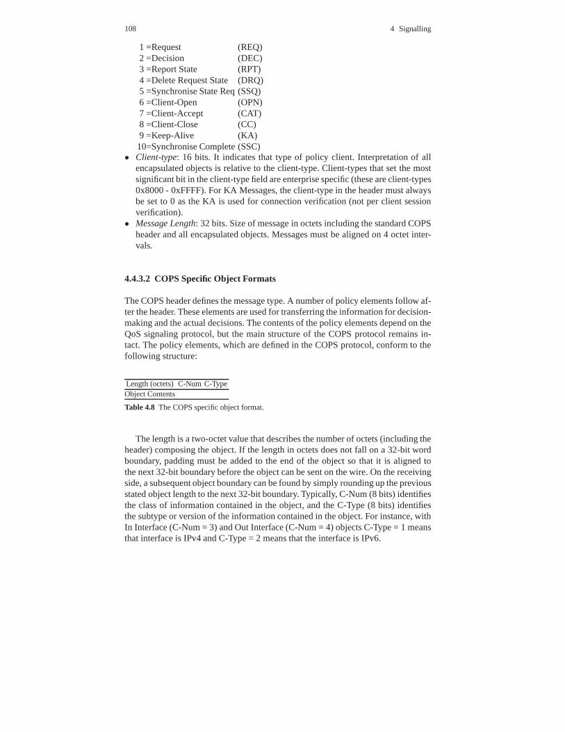
108 4 Signalling
1 =Request (REQ)2 =Decision (DEC)3 =Report State (RPT)4 =Delete Request State (DRQ)5 =Synchronise State Req (SSQ)6 =Client-Open (OPN)7 =Client-Accept (CAT)8 =Client-Close (CC)9 =Keep-Alive (KA)10=Synchronise Complete (SSC)
• Client-type: 16 bits. It indicates that type of policy client. Interpretation of allencapsulated objects is relative to the client-type. Client-types that set the mostsignificant bit in the client-type field are enterprise specific (these are client-types0x8000 - 0xFFFF). For KA Messages, the client-type in the header must alwaysbe set to 0 as the KA is used for connection verification (not per client sessionverification).
• Message Length: 32 bits. Size of message in octets including the standard COPSheader and all encapsulated objects. Messages must be aligned on 4 octet inter-vals.
4.4.3.2 COPS Specific Object Formats
The COPS header defines the message type. A number of policy elements follow af-ter the header. These elements are used for transferring theinformation for decision-making and the actual decisions. The contents of the policy elements depend on theQoS signaling protocol, but the main structure of the COPS protocol remains in-tact. The policy elements, which are defined in the COPS protocol, conform to thefollowing structure:
Length (octets) C-Num C-TypeObject Contents
Table 4.8 The COPS specific object format.
The length is a two-octet value that describes the number of octets (including theheader) composing the object. If the length in octets does not fall on a 32-bit wordboundary, padding must be added to the end of the object so that it is aligned tothe next 32-bit boundary before the object can be sent on the wire. On the receivingside, a subsequent object boundary can be found by simply rounding up the previousstated object length to the next 32-bit boundary. Typically, C-Num (8 bits) identifiesthe class of information contained in the object, and the C-Type (8 bits) identifiesthe subtype or version of the information contained in the object. For instance, withIn Interface (C-Num = 3) and Out Interface (C-Num = 4) objectsC-Type = 1 meansthat interface is IPv4 and C-Type = 2 means that the interfaceis IPv6.

4.4 Common Open Policy Service (COPS) 109
The possible values of the C-Num fields and their meanings arepresented in Ta-ble 6.3.2.1. Every COPS specific object has respective contents of the object. Thiscontent is of variable length depending of the C-Num and C-Type. The messagesbetween the PEP and the PDP are constructed from these objects. In the next sub-section some examples of the messages are shown.
C Num Name Explanation1 Handle The Handle Object encapsulates a unique value
that identifies an installed state. This identification isused by most COPS operations.
2 Context Specifies the type of event(s) that triggered the query.Required for request messages.
3 In-Interface This object is used to identify the incoming interfaceon which a particular request applies and the address wherethe received message originated.
4 Out-Interface This object is used to identify the outgoinginterface to which a specific request applies and the addressfor where the forwarded message is to be sent.
5 Reason Code This object specifies the reason why a requeststate was deleted. It appears in the delete request (DRQ)message.
6 Decision Appears in the reply as the decision taken by the PDP7 LPDP Decision May appear in the request as local point decision8 Error Identifies a particular COPS protocol error9 Client Specific Info (SI) This contains client-type specific
information, e.g. the contents of RSVP Path-message, if theclient is RSVP.
10 Keep-alive timer Maximum time interval over which a COPSmessage has to be sent or received
11 PEP Identification Allows client identification to the PDP,required for Client-Open messages
12 Report Type Type of report in request state associatedwith handle
13 PDP Redirect Address A PDP when closing a PEPsession for a particular client-type may optionally use thisobject to redirect the PEP to the specified PDP serveraddress and TCP port number.
14 Last PDP Address Used from PEP to specify the PDPthe last PDP that has accepted to open session sincehe last rebooted, when PDP sends Open message
15 Accounting timer Optional timer value used todetermine the minimum interval betweenaccounting type reports
16 Message Integrity Sequence of number used forauthentication and validating COPS messages
Table 4.9 COPS Specific objects.
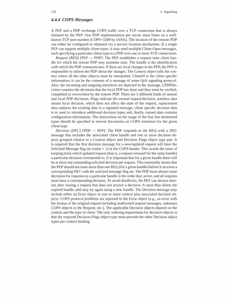
110 4 Signalling
4.4.4 COPS Messages
A PEP and a PDP exchange COPS traffic over a TCP connection thatis alwaysinitiated by the PEP. One PDP implementation per server mustlisten on a well-known TCP port number (COPS=3288 by IANA). The location of the remote PDPcan either be configured or obtained via a service location mechanism. If a singlePEP can support multiple client-types, it may send multipleClient-Open messages,each specifying a particular client-type to a PDP over one ormore TCP connections.
Request (REQ)[PEP→ PDP]: The PEP establishes a request state client han-dle for which the remote PDP may maintain state. The handle isthe identificationwith which the PDP communicates. If there are local changes in the PEP, the PEP isresponsible to inform the PDP about the changes. The Contextobject tells the con-text where all the other objects must be interpreted. ClientSI is the client specificinformation; it can be the contents of a message of some QoS signaling protocol.Also, the incoming and outgoing interfaces are depicted in the message. LPDPDe-cision contains the decisions that the local PDP has done andthey must be verified,completed or overwritten by the remote PDP. There are 5 different kinds of remoteand local PDP decisions. Flags indicate the normal request/decision, stateless datameans local decision, which does not affect the state of the request, replacementdata replaces the existing data in a signaled message, client specific decision datais to used to introduce additional decision types and, finally, named data containsconfiguration information. The instructions on the usage ofthe four last mentionedtypes should be specified in several documents on COPS extension for the givenclient-type.
Decision (DEC)[PDP → PEP]: The PDP responds to the REQ with a DECmessage that includes the associated client handle and one or more decision ob-jects grouped relative to a Context object and Decision Flags object type pair. Itis required that the first decision message for a new/updatedrequest will have theSolicited Message flag set (value = 1) in the COPS header. Thisavoids the issue ofkeeping track which updated request (that is, a request reissued for the same handle)a particular decision corresponds to. It is important that for a given handle there willbe at most one outstanding solicited decision per request. This essentially means thatthe PEP should not issue more than one REQ (for a given handle)before it receives acorresponding DEC with the solicited message flag set. The PDP must always issuedecisions for requests on a particular handle in the order they arrive, and all requestsmust have a corresponding decision. To avoid deadlocks, thePEP can always time-out after issuing a request that does not receive a decision.It must then delete theexpired handle, and may try again using a new handle. The Decision message mayinclude either an Error object or one or more context plus associated decision ob-jects. COPS protocol problems are reported in the Error object (e.g., an error withthe format of the original request including malformed request messages, unknownCOPS objects in the Request, etc.). The applicable Decisionobjects depend on thecontext and the type of client. The only ordering requirement for decision objects isthat the required Decision Flags object type must precede the other Decision objecttypes per context binding.
4.4 Common Open Policy Service (COPS) 111
Report State (RPT)[PEP→ PDP]: The RPT message is used by the PEP tocommunicate to the PDP its success or failure in carrying outthe PDP’s decision,or to report an accounting related change in state. The Report-Type specifies thekind of report and the optional ClientSI can carry additional information per Client-Type. For every DEC message containing a configuration context that is receivedby a PEP, the PEP must generate a corresponding Report State message with theSolicited Message flag set, describing its success or failure in applying the config-uration decision. In addition, outsourcing decisions fromthe PDP may result in acorresponding solicited Report State from the PEP depending on the context andthe type of client. RPT messages solicited by decisions for agiven Client Handlemust set the Solicited Message flag and must be sent in the sameorder as their cor-responding Decision messages were received. There must never be more than oneReport State message generated with the Solicited Message flag set per Decision.The Report State may also be used to provide periodic updatesof client specificinformation for accounting and state monitoring purposes depending on the type ofthe client. In such cases, the accounting report type shouldbe specified, utilising theappropriate client specific information object.
Delete Request State (DRQ)[PEP→ PDP]: This message indicates to the remotePDP that the state identified by the client handle is no longeravailablerelevant. Thisinformation will then be used by the remote PDP to initiate the appropriate house-keeping actions. The reason code object is interpreted withrespect to the client-typeand signifies the reason for the removal. The format of the Delete Request Statemessage is as follows: It is important that when a request state is finally removedfrom the PEP, a DRQ message for this request state is sent to the PDP so the corre-sponding state may likewise be removed on the PDP. Request states not explicitlydeleted by the PEP will be maintained by the PDP until either the client session isclosed or the connection is terminated.
Synchronise State Query (SSQ): This message indicates that the remote PDP re-quests the client (which appears in the common header) to re-send its state. If theoptional Client Handle is present, only the state associated with this handle is syn-chronised. If the PEP does not recognise the requested handle, it must immediatelysend a DRQ message to the PDP for the handle that was specified in the SSQ mes-sage. If no handle is specified in the SSQ message, all of the active client statemust be synchronised with the PDP. The client performs statesynchronisation byre-issuing request queries of the specified client-type forthe existing state in thePEP. When the synchronisation is complete, the PEP must issue a synchronise statecomplete message to the PDP.
Client-Open (OPN)[PEP→ PDP]: The PEP uses the Client-Open message totell the PDP what kind of client-types the PEP support. The PEP can also specifythe last PDP to which the PEP connected. The PEPID is a symbolic name of thePEP, which identifies it inside the administrative domain. The identifier is an ASCIIstring that can be an IP address or DNS name of the PEP. The PEP can forward someadditional client specific information to the PDP. The last PDP address describes thelast PDP for which the PEP is still caching decisions. The integrity object is used ifsecurity is in use or when the security is wanted in the usage.

112 4 Signalling
Client-Accept (CAT)[PDP→ PEP]: The Client-Accept message is used to pos-itively respond to the Client-Open message. This message will return to the PEP atimer object, indicating the maximum time interval betweenkeep-alive messages.Optionally, a timer specifying the minimum allowed interval between accountingreport messages may be included when applicable. If the PDP refuses the client, itwill instead issue a Client-Close message. The Keep-Alive (KA) timer correspondsto maximum acceptable intermediate time between the generation of messages bythe PDP and PEP. The timer value is determined by the PDP and isspecified in sec-onds. A timer value of 0 implies no secondary connection verification is necessary.The optional Accounting (ACCT) timer allows the PDP to indicate to the PEP thatperiodic accounting reports should not exceed the specifiedtimer interval per clienthandle. This allows the PDP to control the rate at which accounting reports are sentby the PEP (when applicable). In general, accounting type Report messages are sentto the PDP when determined appropriate by the PEP. The accounting timer is merelyused by the PDP to keep the rate of such updates in check (i.e.,preventing the PEPfrom blasting the PDP with accounting reports). Not including this object impliesthat there are no PDP restrictions on the rate at which accounting updates are gen-erated. If the PEP receives a malformed Client-Accept message, it must generate aClient-Close message specifying the appropriate error code.
Client-Close (CC)[PEP→ PDP, PDP→ PEP]: The Client-Close message can beissued by either the PDP or PEP to notify each other that a particular type of clientis no longer being supported. The Error object is included todescribe the reason forthe closing (e.g., the requested client-type is not supported by the remote PDP orclient failure).
Keep-Alive (KA)[PEP→ PDP, PDP→ PEP]: The keep-alive message must betransmitted by the PEP within the period defined by the minimum of all KA Timervalues specified in all received CAT messages for the connection. A KA messagemust be generated randomly between1
4 and 34 of this minimum KA timer interval.
When the PDP receives a keep-alive message from a PEP, it mustecho a keep-aliveback to the PEP. This message provides validation for each side that the connec-tion is still functioning even when there is no other messageexchange. Note: Theclient-type in the header must always be set to 0, as the KA is used for connectionverification (not per client session verification). Both client and server may assumethe TCP connection is insufficient for the client-type with the minimum time value(specified in the CAT message), if no communication activityis detected for a pe-riod exceeding the timer period. For the PEP, such detectionimplies the remote PDPor connection is down and the PEP should now attempt to use an alternativebackupPDP.
Synchronise State Complete (SSC)[PEP→ PDP]: The Synchronise State Com-plete is sent by the PEP to the PDP after the PDP sends a synchronise state requestto the PEP and the PEP has finished synchronisation. It is useful, since the PDP willknow when all of the old client state has been successfully re-requested and, thus,the PEP and PDP are completely synchronised. The Client Handle object only needsto be included if the corresponding Synchronise State Message originally referenceda specific handle.
4.4 Common Open Policy Service (COPS) 113
4.4.5 Common Operation
COPS supports two models of policy control: outsourcing andconfiguration (alsoknown as provisioning). In the outsourcing model the PEP contacts the PDP everytime a policy decision has to be made. The PDP makes the decision and commu-nicates it back to the PEP, which enforces it. In the configuration model the PDPconfigures the PEP with the policy to be used. The PEP stores the policy receivedfrom the PDP locally and uses it to make decisions instead of contacting the PDPevery time a new event occurs.
4.4.5.1 Outsourcing Operation
In the outsourcing scenario the PEP contacts the PDP every time a policy decisionneeds to be made. Since the request is stateful, the request will be remembered, orinstalled, on the remote PDP. The unique handle (unique per TCP connection andclient-type), specified in both the request and its corresponding decision identifiesthis request state. The PEP is responsible for deleting thisrequest state once therequest is no longer applicable. The PEP can update a previously installed requeststate by re-issuing a request for the previously installed handle. The remote PDPis then expected to make new decisions and send a decision message back to thePEP. Likewise, the server may change a previously issued decision on any currentlyinstalled request state at any time by issuing an unsolicited decision message. Atall times the PEP module is expected to enforce the PDP’s decisions and notify thePDP of any state changes. An example of this model is COPS usage for RSVP.RSVP-enabled routers, which act as PEPs and use COPS client-type 1, query thePDP when an RSVP message is received. The client specifies which RSVP messagewas received (e.g., PATH or RESV) and the expected behaviourof the router. ThePDP decides whether or not the requested reservation is acceptable, according to thepolicy of the domain and communicates its decision back to the PEP (e.g., removethe resources assigned to a particular flow).
4.4.5.2 Configuration Operations
In the configuration scenario (known as COPS-PR), the PDP provides PEPs withpolicies and the PEP applies these policies. The PDP will then potentially send sev-eral decisions containing named units of configuration datato the PEP. The PEPis expected to install and use the configuration locally. When the PDP no longerwishes that the PEP uses a piece of configuration information, it will send a deci-sion message specifying the named configuration and a decision flags object withthe remove configuration command. The PEP should then proceed to remove thecorresponding configuration and send a report message to thePDP that specifies ithas been deleted. When the client downloads this policy, it does not need to con-tact the server to make individual decisions. This makes COPS-PR a highly scalable

114 4 Signalling
protocol; moreover, the COPS-PR could potentially be used to transfer configurationparameters beyond policy information.
4.4.5.3 Security
In the typical exchanges between remote PDP servers and PEP clients there are alsothe COPS security messages. If COPS level security is required, it must be nego-tiated during the initial Client-Open/Client-Accept message exchange specifying aClient-Type of zero (which is reserved for connection levelsecurity negotiation andconnection verification). Security can be initiated by the PEP, if the PDP accepts thePEP’s security key and algorithm by validating the message digest using the iden-tified key, the PDP must send a Client-Accept message with a Client-Type of zeroto the PEP carrying an Integrity object. This Integrity object will contain the initialsequence number that the PDP requires the PEP to increment during all subsequentcommunication with the PDP and the Key ID, identifying the key and algorithmused to compute the digest. The COPS protocol provides the Integrity object thatcan achieve authentication, message integrity, and replayprevention. Furthermore,it is good practice to use localised keys specific to a particular PEP such that a stolenPEP will not compromise the security of an entire administrative domain. The COPSIntegrity object also provides sequence numbers to avoid replay attacks. The PDPchooses the initial sequence number for the PEP and the PEP chooses the initialsequence number for the PDP. These initial numbers are then incremented witheach successive message sent over the connection in the corresponding direction.The initial sequence numbers should be chosen such that theyare monotonicallyincreasing and never repeat for a particular key. Security between the client (PEP)and server (PDP) may be provided by IP Security [IPSEC]. In this case, the IPSECAuthentication Header (AH) should be used for the validation of the connection.Additionally, IPSEC Encapsulation Security Payload (ESP)may be used to provideboth validation and secrecy.
4.4.6 Illustrative Examples, Using COPS for RSVP
4.4.6.1 Unicast Flow Example
This subsection details the steps in using COPS for controlling a Unicast RSVPflow. It details the contents of the COPS messages with respect to Figure 4.13.
The PEP router has two interfaces (if1, if2). Sender S1 sendsto receiver R1. APath message arrives from S1:
PEP --> PDP REQ := <Handle A><Context: in & out, Path><In-Interface if2> <Out-Interface if1><ClientSI: all objects in Path message>
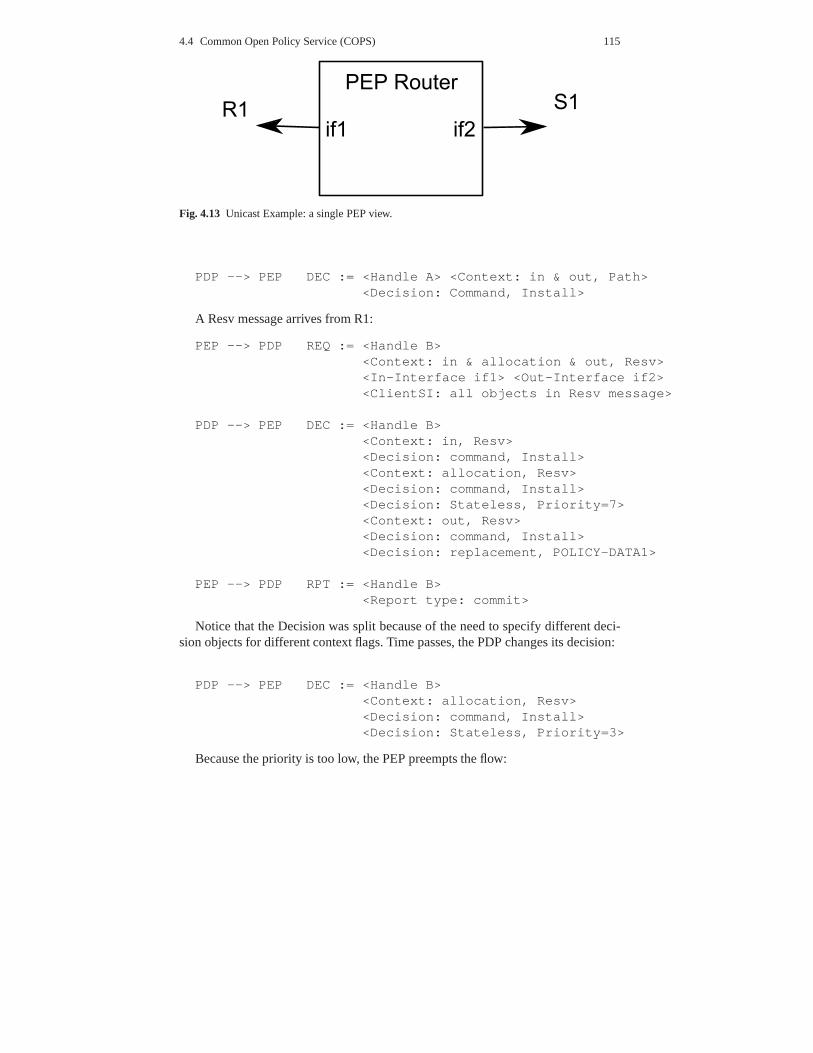
4.4 Common Open Policy Service (COPS) 115
Fig. 4.13 Unicast Example: a single PEP view.
PDP --> PEP DEC := <Handle A> <Context: in & out, Path><Decision: Command, Install>
A Resv message arrives from R1:
PEP --> PDP REQ := <Handle B><Context: in & allocation & out, Resv><In-Interface if1> <Out-Interface if2><ClientSI: all objects in Resv message>
PDP --> PEP DEC := <Handle B><Context: in, Resv><Decision: command, Install><Context: allocation, Resv><Decision: command, Install><Decision: Stateless, Priority=7><Context: out, Resv><Decision: command, Install><Decision: replacement, POLICY-DATA1>
PEP --> PDP RPT := <Handle B><Report type: commit>
Notice that the Decision was split because of the need to specify different deci-sion objects for different context flags. Time passes, the PDP changes its decision:
PDP --> PEP DEC := <Handle B><Context: allocation, Resv><Decision: command, Install><Decision: Stateless, Priority=3>
Because the priority is too low, the PEP preempts the flow:

116 4 Signalling
PEP --> PDP DRQ := <Handle B><Reason Code: Preempted>
Time Passes, the sender S1 ceases to send Path messages:
PEP --> PDP DRQ := <Handle A><Reason: Timeout>
4.5 Conclusions
This chapter provided an overview on the signalling protocols and analysed in detailthree of the most popular and promising signalling protocols/frameworks that areused in the current Internet: the Session Initiation Protocol (SIP), the Next StepsIn Signalling (NSIS) framework, and the Common Open Policy Service (COPS)architecture and protocol.
For each signalling protocol/framework, background information was given andthe main characteristics were described, presenting the overall architecture andoverview of the protocol structure. The descriptions included architectural and pro-tocol overviews, message formats, common operation and some examples.

References 255
References
1. R. Steinmetz and K. Nahrstedt,Multimedia Fundamentals: Medai Coding and Content Pro-cessing, 2nd ed. Prentice-Hall PTR, 2002, vol. 1.
2. ——,Multimedia Systems, 1st ed. Berlin, Germany: Springer Verlag, 2004.3. S. Floyd, “Connections with multiple congested gatewaysin packet-switched networks part
1: One-way traffic,”Computer Communications Review, vol. 21, no. 5, pp. 30–47, October1991.
4. M. Mathis, J. Semke, and J. Mahdavi, “The macroscopic behavior of the tcp congestionavoidance algorithm,”SIGCOMM Comput. Commun. Rev., vol. 27, no. 3, pp. 67–82, 1997.
5. ITU-T, “Itu t recommendation g.114: One-way transmission time.” 2003.6. ——, “Itu t recommendation g.1010: End-user multimedia qos categories.” 2001.7. T. Szigeti and C. Hattingh,End-to-End QoS Network Design: Quality of Service in LANs,
WANs, and VPNs (Networking Technology). CISCO Press, 2005.8. S. Keshav,An Engineering Approach to Computer Networking. Addison Wesley, 1997.9. R. Braden, D. Clark, and S. Shenker, “Integrated servicesin the internet architecture: an
overview,” RFC 1633, June 1994.10. S. Shenker and J. Wroclawski, “General characterization parameters for integrated service
network elements,” RFC 2215, September 1997.11. J. Wroclawski, “Specification of the Controlled-Load Network Element Service,” RFC 2211
(Proposed Standard), September 1997. [Online]. Available: http://www.ietf.org/rfc/rfc2211.txt
12. S. Shenker, C. Partridge, and R. Guerin, “Specification of Guaranteed Qualityof Service,” RFC 2212 (Proposed Standard), September 1997.[Online]. Available:http://www.ietf.org/rfc/rfc2212.txt
13. J. Solomon, “Applicability Statement for IP Mobility Support,” RFC 2005 (ProposedStandard), Oktober 1996. [Online]. Available: http://www.ietf.org/rfc/rfc2005.txt
14. S. Blake, D. Black, M. Carlson, E. Davies, Z. Wang, and W. Weiss, “An Architecture forDifferentiated Service,” RFC 2475 (Informational), Dezember 1998, updated by RFC 3260.[Online]. Available: http://www.ietf.org/rfc/rfc2475.txt
15. K. Nichols, S. Blake, F. Baker, and D. Black, “Definition of the Differentiated ServicesField (DS Field) in the IPv4 and IPv6 Headers,” RFC 2474 (Proposed Standard), Dezember1998, updated by RFCs 3168, 3260. [Online]. Available: http://www.ietf.org/rfc/rfc2474.txt
16. K. Nichols and B. Carpenter, “Definition of Differentiated Services Per Domain Behaviorsand Rules for their Specification,” RFC 3086 (Informational), April 2001. [Online].Available: http://www.ietf.org/rfc/rfc3086.txt
17. K. Nichols, V. Jacobson, and K. Poduri, “A per-domain behavior for circuit emulation in ipnetworks,”SIGCOMM Comput. Commun. Rev., vol. 34, no. 2, pp. 71–83, 2004.
18. B. Davie, A. Charny, J. Bennet, K. Benson, J. L. Boudec, W.Courtney, S. Davari,V. Firoiu, and D. Stiliadis, “An Expedited Forwarding PHB (Per-Hop Behavior),” RFC 3246(Proposed Standard), Marz 2002. [Online]. Available: http://www.ietf.org/rfc/rfc3246.txt
19. J. Heinanen, F. Baker, W. Weiss, and J. Wroclawski, “Assured Forwarding PHB Group,”RFC 2597 (Proposed Standard), June 1999, updated by RFC 3260. [Online]. Available:http://www.ietf.org/rfc/rfc2597.txt
20. J. Babiarz, K. Chan, and F. Baker, “Configuration Guidelines for DiffServ ServiceClasses,” RFC 4594 (Informational), August 2006. [Online]. Available: http://www.ietf.org/rfc/rfc4594.txt
21. L. Breslau, E. W. Knightly, S. Shenker, I. Stoica, and H. Zhang, “Endpoint admission control:architectural issues and performance,” inSIGCOMM ’00: Proceedings of the conferenceon Applications, Technologies, Architectures, and Protocols for Computer Communication.New York, NY, USA: ACM, 2000, pp. 57–69.
22. K. Ramakrishnan and S. Floyd, “A Proposal to add ExplicitCongestion Notification (ECN)to IP,” RFC 2481 (Experimental), Januar 1999, obsoleted by RFC 3168. [Online]. Available:http://www.ietf.org/rfc/rfc2481.txt
256 B Network Emulation Focusing on QoS-Oriented SatelliteCommunication
23. C. Cetinkaya, V. Kanodia, and E. W. Knightly, “Scalable services via egress admissioncontrol,” IEEE Transactions on Multimedia, vol. 3, no. 1, pp. 69–81, 2001. [Online].Available: citeseer.ist.psu.edu/cetinkaya01scalable.html
24. S. McCanne, V. Jacobson, and M. Vetterli, “Receiver-driven layered multicast,” inACM SIG-COMM, vol. 26, no. 4. New York: ACM Press, Aug. 1996, pp. 117–130.
25. V. Paxson, “Strategies for Sound Internet Measurement,” in 4rth Internet Measurements Con-ference, 2004.
26. V. Paxson, G. Almes, J. Mahdavi, and M. Mathis, “Framework for IP Performance Metrics,”RFC 2330, May 1998.
27. J. Mahdavi and V. Paxson, “IPPM Metrics for Measuring Connectivity,” RFC 2678, Sept.1999.
28. G. Almes, S. Kalidindi, and M. Zekauskas, “A One-way Delay Metric for IPPM,” RFC 2679,Sept. 1999.
29. I.-T. R. Y.1541, “Network Performance Objectives fo IP-based Services,” Review Jan 2005.30. G. Almes, S. Kalidindi, and M. Zekauskas, “A Round-trip Delay Metric for IPPM,” RFC
2681, Sept. 1999.31. ——, “A One-way Packet Loss Metric for IPPM,” RFC 2680, Sept. 1999.32. C. Demichelis and P. Chimento, “IP Packet Delay Variation Metric for IP Performance Met-
rics (IPPM),” RFC 3393, Nov. 2002.33. M. Mathis and M. Allman, “A Framework for Defining Empirical Bulk Transfer Capacity
Metrics,” RFC 3148, July 2001.34. I.-T. R. P.800.1, “Mean Opinion Score (MOS) terminology,” 2003.35. A. Takahashi, H. Yoshino, and N. Kitawaki, “Perceptual qos assessment technologies for
voip,” IEEE/Comm. Mag, vol. 42, no. 7, pp. 28–34, 2004.36. I.-T. R. G.107, “The E-model, a computational model for use in transmission planning,”
2003.37. I.-T. R. P.910, “Subjective video quality assessment methods for multimedia applications,”
1999.38. I.-T. R. P.862, “Perceptual evaluation of speech quality (PESQ): An objective method
for end-to-end speech quality assessment of narrow-band telephone networks and speechcodecs,” 2001.
39. D. L. Mills, “Network Time Protocol (Version 3) Specification, Implementation and Analy-sis,” RFC 1305, Mar. 1992.
40. D. Veitch, S. Babu, and A. Pasztor, “Robust synchronization of software clocks across theinternet,” inInternet Measurement Conference (IMC ’04), 2004.
41. N. Duffeld, “Sampling for passive internet measurement: A review,” Statistical Science,vol. 19, no. 3, pp. 472–498, 2004.
42. J. Quittek, T. Zseby, B. Claise, and S. Zander, “Requirements for IP Flow Information Export(IPFIX),” RFC 3917, Oct. 2004.
43. M. Crovella and B. Krishnamurthy,Internet Measurement. Infrastructure, Traffic, and Appli-cations. John Wiley & Sons, Ltd, 2006.
44. D. Harrington, R. Presuhn, and B. Wijnen, “An architecture for describing simple networkmanagement protocol (snmp) management frameworks,” RFC 3411, Dec. 2002.
45. “Lobster - Large-scale Monitoring of Broadband Internet Infrastructures,” http://www.ist-lobster.org.
46. N. G. Duffield and M. Grossglauser, “Trajectory samplingfor direct traffic observation,”IEEE/ACM Trans. Netw., vol. 9, no. 3, pp. 280–292, 2001.
47. T. Zseby, S. Zander, and G. Carle, “Evaluation of Building Blocks for Passive One-Way-Delay Measurements,” inPassive and Active Measurements Conference, 2001.
48. S. B. Moon, “Measurement and Analysis of End-to-end Delay and Loss in the Internet,”Ph.D. dissertation, University of Massachusetts, 2000.
49. J. Strauss, D. Katabi, and F. Kaashoek, “A measurement study of available bandwidth esti-mation tools,” inInternet Measurement Conference (IMC), 2003.
References 257
50. L. Lao, C. Dovrolis, and M. Y. Sanadidi, “The probe gap model can underestimate the avail-able bandwidth of multihop paths,”SIGCOMM Comput. Commun. Rev., vol. 36, no. 5, pp.29–34, 2006.
51. B. Melander, M. Bjorkman, and P. Gunningberg, “A New End-to-End Probing and AnalysisMethod for Estimating Bandwidth Bottlenecks,” inIEEE Globecom Global Internet Sympo-sium, 2000.
52. Q. Liu and J.-N. Hwang, “End-to-end available bandwidthestimation and time measurementadjustment for multimedia qos,” inICME ’03: Proceedings of the 2003 International Con-ference on Multimedia and Expo - Volume 3 (ICME ’03). Washington, DC, USA: IEEEComputer Society, 2003, pp. 373–376.
53. A. Pasztor and D. Veitch, “Active Probing using Packet Quartets,” inInternet MeasurementWorkshop, 2002.
54. R. Jain and S. A. Routhier, “Packet Trains-Measurementsand a New Model for ComputerNetwork Traffic,” IEEE Journal of Selected Areas in Communications, vol. SAC-4, no. 6, pp.986–995, 1986.
55. C. Dovrolis, P. Ramanathan, and D. Moore, “Packet-dispersion techniques and a capacity-estimation methodology,”IEEE/ACM Trans. Netw., vol. 12, no. 6, pp. 963–977, 2004.
56. “PlanetLab: An open platform for developing, deploying, and accessing planetary-scale ser-vices,” http://www.planet-lab.org/.
57. “Cooperative Association for Internet Data Analysis (CAIDA),” http://www.caida.org/.58. “Active Measurement Project (AMP),” http://amp.nlanr.net/.59. F. Georgatos, F. Gruber, D. Karrenberg, M. Santcroos, A.sanj, H. Uijterwaal, and R. Wilhem,
“Providing Active Measurements as a Regular Service for ISP’s,” in Proceedings of Passiveand Active Measurement, 2001.
60. “Evergrow Traffic Observatory Measurement InfrastruCture,” http://www.etomic.org/.61. “DIMES (Distributed Internet MEasurements & Simulations),” http://www.netdimes.org/.62. “Ever-growing global scale-free networks, their provisioning, repair and unique functions,”
http://www.evergrow.org/.63. S. Shalunov, B. Teitelbaum, A. Karp, J. W. Boote, and M. J.Zekauskas, “One-Way Active
Measurements Protocol,” RFC 4656, Sept. 2006.64. S. McCanne and V. Jacobson, “The BSD Packet Filter: A New Architecture for User-level
Packet Capture,” inUSENIX Winter, 1993.65. “perfSONAR - PERFormance Service-Oriented Network monitoring ARchitecture,” http:
//www.perfsonar.net.66. I. Miloucheva, P. Gutierrez, D. Hetzer, A. Nassri, and M.Beoni, “Intermon architecture for
complex QoS analysis in inter-domain environment based on discovery of topology and traf-fic impact,” in Inter-domain Performance and Simulation Workshop, Budapest, March 2004.
67. “Passive Measurement and Analysis (PMA),” http://pma.nlanr.net/.68. D. Awduche, J. Malcolm, J. Agogbua, M. O’Dell, and J. McManus, “Requirements
for Traffic Engineering Over MPLS,” RFC 2702 (Informational), Sept. 1999. [Online].Available: http://www.ietf.org/rfc/rfc2702.txt
69. E. Rosen, D. Tappan, G. Fedorkow, Y. Rekhter, D. Farinacci, T. Li, and A. Conta, “MPLSLabel Stack Encoding,” RFC 3032 (Proposed Standard), Jan. 2001, updated by RFCs 3443,4182. [Online]. Available: http://www.ietf.org/rfc/rfc3032.txt
70. L. Andersson, P. Doolan, N. Feldman, A. Fredette, and B. Thomas, “LDP Specification,”RFC 3036 (Proposed Standard), Jan. 2001. [Online]. Available: http://www.ietf.org/rfc/rfc3036.txt
71. H. Smit and T. Li, “Intermediate System to Intermediate System (IS-IS) Extensions forTraffic Engineering (TE),” RFC 3784 (Informational), June 2004, updated by RFC 4205.[Online]. Available: http://www.ietf.org/rfc/rfc3784.txt
72. D. Katz, K. Kompella, and D. Yeung, “Traffic Engineering (TE) Extensions to OSPFVersion 2,” RFC 3630 (Proposed Standard), Sept. 2003, updated by RFC 4203. [Online].Available: http://www.ietf.org/rfc/rfc3630.txt
258 B Network Emulation Focusing on QoS-Oriented SatelliteCommunication
73. R. Braden, L. Zhang, S. Berson, S. Herzog, and S. Jamin, “Resource ReSerVation Protocol(RSVP) – Version 1 Functional Specification,” RFC 2205 (Proposed Standard), Sept. 1997,updated by RFCs 2750, 3936, 4495. [Online]. Available: http://www.ietf.org/rfc/rfc2205.txt
74. D. Awduche, L. Berger, D. Gan, T. Li, V. Srinivasan, and G.Swallow, “RSVP-TE:Extensions to RSVP for LSP Tunnels,” RFC 3209 (Proposed Standard), Dec. 2001, updatedby RFCs 3936, 4420, 4874. [Online]. Available: http://www.ietf.org/rfc/rfc3209.txt
75. B. Jamoussi, L. Andersson, R. Callon, R. Dantu, L. Wu, P. Doolan, T. Worster, N. Feldman,A. Fredette, M. Girish, E. Gray, J. Heinanen, T. Kilty, and A.Malis, “Constraint-BasedLSP Setup using LDP,” RFC 3212 (Proposed Standard), Jan. 2002, updated by RFC 3468.[Online]. Available: http://www.ietf.org/rfc/rfc3212.txt
76. D. Grossman, “New Terminology and Clarifications for Diffserv,” RFC 3260 (Informa-tional), Apr. 2002. [Online]. Available: http://www.ietf.org/rfc/rfc3260.txt
77. F. Le Faucheur, L. Wu, B. Davie, S. Davari, P. Vaananen, R.Krishnan, P. Cheval,and J. Heinanen, “Multi-Protocol Label Switching (MPLS) Support of DifferentiatedServices,” RFC 3270 (Proposed Standard), May 2002. [Online]. Available: http://www.ietf.org/rfc/rfc3270.txt
78. F. L. Faucheur and W. Lai, “Requirements for Support of Differentiated Services-awareMPLS Traffic Engineering,” RFC 3564 (Informational), July 2003. [Online]. Available:http://www.ietf.org/rfc/rfc3564.txt
79. F. Le Faucheur and W. Lai, “Maximum Allocation BandwidthConstraints Model forDiffserv-aware MPLS Traffic Engineering,” RFC 4125 (Experimental), June 2005. [Online].Available: http://www.ietf.org/rfc/rfc4125.txt
80. F. Le Faucheur, “Russian Dolls Bandwidth Constraints Model for Diffserv-awareMPLS Traffic Engineering,” RFC 4127 (Experimental), June 2005. [Online]. Available:http://www.ietf.org/rfc/rfc4127.txt
81. W. Lai, “Bandwidth Constraints Models for Differentiated Services (Diffserv)-aware MPLSTraffic Engineering: Performance Evaluation,” RFC 4128 (Informational), June 2005.[Online]. Available: http://www.ietf.org/rfc/rfc4128.txt
82. F. Le Faucheur, “Protocol Extensions for Support of Diffserv-aware MPLS TrafficEngineering,” RFC 4124 (Proposed Standard), June 2005. [Online]. Available: http://www.ietf.org/rfc/rfc4124.txt
83. R. Stewart, Q. Xie, K. Morneault, and H. Schwarzbauer, “Stream Control Transmission Pro-tocol,” IETF, Tech. Rep. 2960, 2000.
84. T. Dierks and C. Allen, “The TLS Protocol,” IETF, Tech. Rep. 2246, 1999.85. D. Katz, “Router Alert Option,” IETF, Tech. Rep. 2113, 1997.86. M.Stiemerling, H.Tschofenig, C. Aoun, and E. Davies, “Nat/firewall nsis signaling layer
protocol (nslp),” IETF,” internet draft, 2006.87. D.Durham, J.Boyle, R.Cohen, S.Herzog, R.Rajan, and A.Sastry, “The COPS (Common Open
Policy Service) Protocol,” IETF, Tech. Rep. 2748, 2000.88. isox214, “ITU-T recommendation X.214 (11/95) information technology,” Nov. 1995.89. J. Postel, “Transmission control protocol: DARPA internet program protocol specification,”
IETF, Request For Comments 793, 1981.90. ——, “User datagram protocol (UDP),” IETF, Request For Comments 768, Aug. 1980.91. H.Schulzrinne, S.Casner, R. Frederick, and V. Jacobson, “An extension to the Selective Ac-
knowledgment (SACK) Options for TCP,” IETF, Task Force 3550, 2003.92. V. Jacobson and R. Braden, “TCP extensions for long-delay paths,” IETF, Request For Com-
ments 1072, Oct. 1988.93. V. Jacobson, R. Braden, and D. Borman, “Tcp extensions for high performance,” IETF, Re-
quest For Comments 1323, 1992.94. L. S. Brakno and L. L. Peterson, “TCP Vegas: End to End congestion Avoidance on a Global
Internet,”IEEE Journal on Selected Areas in Communications, no. 13, pp. 1465–1480, 1995.95. S. Floyd, T. Henderson, and A. Gurtov, “The newreno modification to tcp’s fast recovery
algorithm,” IETF, Request For Comments 3782, Apr. 2004.96. S. Floyd, J. Mahdavi, M. Mathis, and M. Podolsky, “An extension to the selective acknowl-
edgement (SACK) option for TCP,” IETF, Request For Comments2883, July 2000.

References 259
97. O. Ait-Hellal and E. Altman, “Analysis of tcp-vegas and tcp-reno,” inProc. of the IEEEInternational Conference on Communications - ICC, 1997, pp. 495–499.
98. V. Jacobson, L. Peterson, L. Brakmo, and S. Floyd, “Problems with arizona’s vegas,” mailinglist, end2end-tf, Tech. Rep., 1994, ftp://ftp.ee.lbl.gov/email/vanj.94mar14.txt.
99. L. Xu, K. Harfoush, and I. Rhee, “Binary increase congestion control for fast long-distancenetworks,” inProc. of IEEE INFOCOM, Mar. 2004, pp. 2514–2524.
100. S. Floyd, “Highspeed tcp for large congestion windows,” IETF, Request For Comments3649, Dec. 2003.
101. D. Katabi, M. Handley, and C. Rohrs, “Congestion control for high bandwidth-delay productnetworks,” inProc. of ACM SIGCOMM, 2002.
102. Y. Xia, L. Subramanian, I. Stoica, and S. Kalyanaraman,“One more bit is enough,” inProc.of ACM SIGCOMM, 2005.
103. K. Ramakrishnan, S. Floyd, and D. Black, “The addition of explicit congestion notification(ECN) to ip,” IETF, Request For Comments 3168, Sept. 2001.
104. P. Sinha, T. Nandagopal, N. Venkitaraman, R. Sivakumar, and V. Bharghavan, “WTCP: Areliable transport protocol for wireless wide-area networks,” Wireless Networks, vol. 8, no.2-3, pp. 301–316, 2002.
105. M. Gerla, M. Y. Sanadidi, R. Wang, A. Zanella, C. Casetti, and S. Mascolo, “Tcp westwood:congestion window control using bandwidth estimation,” inProc. of IEEE GLOBECOM,2001, pp. 1698–1702.
106. C. P. Fu and S. C. Liew, “Tcp veno: Tcp enhancement for transmission over wireless accessnetworks,”IEEE Journal on Selected Areas in Communications, vol. 21, no. 2, pp. 216–229,Feb. 2003.
107. R. S. et Al., “Sockets API extensions for stream controltransmission protocol (SCTP),”IETF, Internet Draft draft-ietf-tsvwg-sctpsocket-06.txt, Mar. 2003.
108. E. Kohler, M. Handley, and S. Floyd, “Datagram congestion control protocol (DCCP),” IETF,Request For Comments 4340, Mar. 2006.
109. S. Floyd and E. Kohler, “Profile for DCCP Congestion Control ID 2: TCP-like CongestionControl,” IETF, Request For Comments 4341, Mar. 2006.
110. S. Floyd, E. Kohler, and J. Padhye, “Profile for DCCP congestion control ID 3: TRFC con-gestion control,” IETF, Request For Comments 4342, Mar. 2006.
111. M. Handley, S. Floyd, J. Pahdye, and J. Widmer, “Tcp-friendly rate control (TFRC): Protocolspecification,” IETF, Request For Comments 3448, Jan. 2003.
112. S. Iren, P. D. Amer, and P. T. Conrad, “The transport layer: tutorial and survey,”ACM Com-puter Survey, vol. 31, no. 4, pp. 360–404, 1999.
113. S. Floyd, “Congestion control principles,” IETF, Request For Comments 2914, Sept. 2000.114. Y.-Q. Z. D. Wu, T. Hou, “Transporting real-time video over the internet: Challenges and
approaches,” inProc. of the IEEE, vol. 88, no. 12, Dec. 2000, pp. 1855–1875.115. V. Jacobson, “Congestion avoidance and control,” inProc. of ACM SIGCOMM, Stanford,
CA, Aug. 1988, pp. 314–329.116. R. Talluri, “Error-resilience video coding in the ISO MPEG-4 standard,”IEEE Communica-
tions Magazine, pp. 112–119, June 1998.117. Y. Wang and Q.-F. Zhu, “Error control and concealment for video communication: A review,”
in Proc. of the IEEE, vol. 86, no. 5, May 1998, pp. 974–997.118. M. Mathis, J. Mahdavi, S. Floyd, and A. Romanow, “TCP selective acknowledgment op-
tions,” IETF, Request For Comments 2018, Oct. 1996.119. J. Widmer, “Equation-based congestion control,” Diploma Thesis, University of Mannheim,
Germany, Feb. 2000.120. S. Floyd and K. Fall, “Promoting the use of end-to-end congestion control in the internet,”
IEEE/ACM Transactions on Networking, vol. 7, no. 4, pp. 458–472, 1999.121. P. Amer, C. Chassot, C. Connolly, P. Conrad, and M. Diaz,“Partial order transport service
for MM and other application,”IEEE/ACM Transactions on Networking, vol. 2, no. 5, 1994.122. L. Rojas-Cardenas, E. Chaput, L. Dairaine, P. Snac, andM. Diaz, “Video transport over
partial order connections,”Computer Networks, vol. 31, no. 7, pp. 709–725, Apr. 1999.
260 B Network Emulation Focusing on QoS-Oriented SatelliteCommunication
123. J.-P. V. A. Farrel and J. Ash, “A Path Computation Element (PCE)-Based Architecture,” TheInternet Society, Request For Comments 4655, Aug. 2006.
124. J. Enrıquez, M. A. Callejo, and et al., “EuQoS Architecture Deliverable D122,” 2007.125. A. Beben, “EQ-BGP: an efficient inter-domain QoS routing protocol,” inAINA ’06: Proceed-
ings of the 20th IEEE International Conference on Advanced Information Networking andApplications. Los Alamitos, CA, United States: IEEE Computer Society, Apr. 2006, pp.560–564.
126. X. Masip-Bruin, M. Yannuzzi, R. Serral-Gracia, J. Domingo-Pascual, J. Enriquez-Gabeiras,M. Callejo, M. Diaz, F.Racaru, G. Stea, E. Mingozzi, A. Beben, W. Burakowski, E. Mon-teiro, and L. Cordeiro, “The EuQoS System: A solution for QoSRouting in HeterogeneousNetworks,”IEEE Communications Magazine, vol. 45, no. 2, Feb. 2007.
127. Y. Rekhter, T. Li, and S. Hares, “A Border Gateway Protocol 4 (BGP-4),” The Internet Soci-ety, Request For Comments 4271, Jan. 2006.
128. L. Baresse and et al., “Integrated EuQoS system Software architecture for application usecases and API for application driving Deliverable D421.”
129. P. Krawiec and W. Burakowski, “Resource allocation strategies for new connections in qosmulti-domain networks with signaling capabilities,” inProceedings of Australian Telecom-munication Networks and Applications Conference 2007 (ATNAC 2007), Christchurch, NewZealand, Dec. 2007, pp. 337–342.
130. A. Beben and et al., “Definition of measurement and monitoring system for Phase 2 Deliver-able D222.”
131. A. Bak, W. Burakowski, F. Ricciato, S. Salsano, and H. Tarasiuk, “A framework for providingdifferentiated QoS guarantees in IP-based network,”Computer Communications, vol. 26,no. 4, pp. 327–337, 2003.
132. C. Brandauer, W. Burakowski, M. Dabrowski, B. Koch, andH. Tarasiu, “AC algorithms inAQUILA QoS IP network,”European Transactions on Telecommunications, vol. 16, no. 3,pp. 225–232, 2005.
133. M. Dabrowski, G. Eichler, M. Fudala, D. Katzengruber, T. Kilkanen, N. Miettinen, H. Tara-siuk, and M. Titze, “Evaluation of the AQUILA Architecture:Trial Results for SignallingPerformance, Network Services and User Acceptance,” inArt-QoS, 2003, pp. 218–233.
134. K.Chan, J.Babiarz, and F.Baker, “Aggregation of DiffServ Service Classes,” Transport AreaWorking Group,” Internet-Draft, Nov. 2007.
135. “Nexuiz project,” www.alientrap.org/nexuiz/.136. J. M. Batalla and R. Janowski, “Provisioning dedicatedclass of service for reliable transfer
of signaling traffic,” inInternational Teletraffic Congress, ser. Lecture Notes in ComputerScience, L. Mason, T. Drwiega, and J. Yan, Eds., vol. 4516. Springer, 2007, pp. 853–864.
137. “Medigraf,” http://www.medigraf.pt/.138. J. W. Roberts, U. Mocci, and J. T. Virtamo, Eds.,Broadband Network Teletraffic - Perfor-
mance Evaluation and Design of Broadband Multiservice Networks: Final Report of ActionCOST 242, ser. Lecture Notes in Computer Science. Springer, 1996, vol. 1155.
139. L. Kleinrock,Queueing Systems, Volume 2, Computer Applications. John Wiley & SonsInc, 1976.
140. H. Tarasiuk, R. Janowski, and W. Burakowski, “Admissible traffic load of real time class ofservice for inter-domain peers,” inProceedings of Joint International Conference on Auto-nomic and Autonomous Systems and International Conferenceon Networking and Services(ICAS/ICNS 2005). Papeete, Tahiti, French Polynesia: IEEE Computer Society, Oct. 2005.
141. ——, “Application of Admission Control and Traffic Shaping for providing TCP ThroughputGuarantees,” inProceedings of International Workshop To-QoS’2006 in conjunction withIFIP 2006 Networking Conference (ed. W.Burakowski), Coimbra, Portugal, May 2006, pp.163–172.
142. “IEEE standards for local and metropolitan area networks. Virtual bridged local area net-works,” IEEE Std 802.1Q, 2003 Edition (Incorporates IEEE Std 802.1Q-1998, IEEE Std802.1u-2001, IEEE Std 802.1v-2001, and IEEE Std 802.1s-2002), 2003.
143. “IEEE Standard for Local and metropolitan area networks Media Access Control (MAC)Bridges,”IEEE Std 802.1D-2004 (Revision of IEEE Std 802.1D-1998), 2004.
References 261
144. M. Carmo, J. S. Silva, E. Monteiro, P. Simoes, and F. Boavida, “Ethernet QoS Modelingin Emerging Scenarios,” inProceedings of 3rd International Workshop on Internet Perfor-mance, Simulation, Monitoring and Measurement (IPS-MoMe 2005). Warsaw, Poland: ISTMoMe Cluster, Mar. 2005, pp. 90–96.
145. M. Carmo, B. Carvalho, J. S. Silva, E. Monteiro, P. Simoes, M. Curado, and F. Boavida,“NSIS-based Quality of Service and Resource Allocation in Ethernet Networks,” inPro-ceedings of 4th International Conference on Wired/Wireless Internet Communications 2006,2006.
146. M. Carmo, J. S. Silva, and E. Monteiro, “EuQoS approach for Resource Allocation in Ether-net Networks,”International Journal of Network Management, vol. 17, no. 5, pp. 373–388,sep / oct 2007.
147. “Wireless LAN Medium Access Control (MAC) and PhysicalLayer (PHY) specifications:Amendment 8: Medium Access Control (MAC) Quality of ServiceEnhancements,”IEEEStd 802.11e-2005, 2005.
148. E. Lochin and L. D. A. Jourjon, “gtfrc, a tcp friendly qos-aware rate control for diffservassured service,”Springer Telecommunication Systems, vol. 10.1007/s11235-006-9004-2,ISSN: 1018-4864 (Print) 1572-9451 (Online), September 2006 2006.
149. E. Exposito, P. Senac, and M. Diaz, “Compositional architecture pattern for qos-orientedcommunication mechanisms,” inMMM, Y.-P. P. Chen, Ed. IEEE Computer Society, 2005,pp. 413–420.
150. B. Quinn and K. Almeroth, “Ip multicast applications: Challenges and solutions,” The Inter-net Society, Request For Comments 3170, Sept. 2001.
151. Z. Albanna, K. Almeroth, D. Meyer, and M. Schipper, “Iana guidelines for ipv4 multicastaddress assignments,” The Internet Society, Request For Comments 3171, Aug. 2001.
152. R. Hinden and S. Deering, “Internet protocol version 6 (ipv6) addressing architecture,” TheInternet Society, Request For Comments 3513, Apr. 2003.
153. B. Cain, S. Deering, I. Kouvelas, B. Fenner, and A. Thyagarajan, “Internet group manage-ment protocol, version 3,” The Internet Society, Request For Comments 3376, Oct. 2002.
154. A. Adams, J. Nicholas, and W. Siadak, “Protocol independent multicast - dense mode (pim-dm): Protocol specification (revised),” The Internet Society, Request For Comments 3973,Jan. 2005.
155. B. Fenner, M. Handley, H. Holbrook, and I. Kouvelas, “Protocol independent multicast -sparse mode (pim-sm): Protocol specification (revised),” The Internet Society, Request ForComments 4601, Aug. 2006.
156. D. Waitzman, C. Partridge, and S. Deering, “Distance vector multicast routing protocol,”Network Working Group, Request For Comments 1075, Nov. 1988.
157. J. Moy, “Multicast extensions to ospf,” Network Working Group, Request For Comments1584, Mar. 1994.
158. K. Savetz, N. Randall, and Y. Lepage,MBONE: Multicasting Tomorrow’s Internet. JohnWiley & Sons Inc, 1996.
159. R. Zhang and Y. C. Hu, “Borg: A hybrid protocol for scalable application-level multicast inpeer-to-peer networks,” inNOSSDAV ’03: Proceedings of the 13th international workshopon Network and operating systems support for digital audio and video, ACM. New York,NY, USA: ACM Press, June 2003, pp. 172–179.
160. A. Sobeih, W. Yurcik, and J. C. Hou, “Vring: A case for building application-layer multi-cast rings (rather than trees),” inMASCOTS ’04: Proceedings of the The IEEE ComputerSociety?s 12th Annual International Symposium on Modeling, Analysis, and Simulation ofComputer and Telecommunications Systems (MASCOTS’04). Washington, DC, USA: IEEEComputer Society, 2004, pp. 437–446.
161. S. Q. Zhuang, B. Y. Zhao, A. D. Joseph, R. H. Katz, and J. D.Kubiatowicz, “Bayeux: Anarchitecture for scalable and fault-tolerant wide-area data dissemination,” inNOSSDAV ’01:Proceedings of the 11th international workshop on Network and operating systems supportfor digital audio and video. Port Jefferson, New York, United States: ACM Press, 2001, pp.11–20.
262 B Network Emulation Focusing on QoS-Oriented SatelliteCommunication
162. M. Castro, P. Druschel, A.-M. Kermarrec, A. Nandi, A. Rowstron, and A. Singh, “Split-stream: High-bandwidth multicast in a cooperative environment,” in 19th ACM Symposiumon Operating Systems Principles (SOSP’03), Bolton Landing, New York, USA, oct 2003.
163. A. Rowstron and P. Druschel, “Pastry: Scalable, distributed object location and routing forlarge-scale peer-to-peer systems,” inIFIP/ACM International Conference on Distributed Sys-tems Platforms (Middleware), Heidelberg, Germany, nov 2001, pp. 329–350.
164. M. Castro, P. Druschel, A.-M. Kermarrec, and A. Rowstron, “Scribe: A large-scale and de-centralized application-level multicast infrastructure,” IEEE Journal on Selected Areas inCommunication (JSAC), vol. 20, no. 8, oct 2002.
165. M. Brogle, D. Milic, and T. Braun, “Qos enabled multicast for structured p2p networks,”in 4th IEEE Consumer Communications and Networking Conference, Las Vegas, NV, USA,Jan. 2007.
166. D. Milic, M. Brogle, and T. Braun, “Video broadcasting using overlay multicast,” inSeventhIEEE International Symposium on Multimedia (ISM 2005), Irvine, CA, USA, Dec. 2005, pp.515–522.
167. A. Sulistio, C. S. Yeo, and R. Buyya, “A taxonomy of computer-based simulations and itsmapping to parallel and distributed systems simulation tools,” Softw. Pract. Exper., vol. 34,no. 7, pp. 653–673, 2004.
168. N. Metropolis, A. W. Rosenbluth, M. N. Rosenbluth, A. H.Teller, and E. Teller, “Equationof state calculations by fast computing machines,”The Journal of Chemical Physics, vol. 21,pp. 1087–1092, 1953.
169. T. Yung, J. Martin, M. Takai, and R. Bagrodia, “Integration of fluidbased analytical modelwith packet-level simulation for analysis of computer networks,” 2001.
170. C. Kiddle, R. Simmonds, C. Williamson, and B. Unger, “Hybrid packet/fluid flow networksimulation,” in PADS ’03: Proceedings of the seventeenth workshop on Parallel and dis-tributed simulation. Washington, DC, USA: IEEE Computer Society, 2003, p. 143.
171. J. Incera, R. Marie, D. Ros, and G. Rubino, “Fluidsim: a tool to simulate fluid models ofhigh-speed networks,”Perform. Eval., vol. 44, no. 1-4, pp. 25–49, 2001.
172. B. Liu, D. R. Figueiredo, Y. Guo, J. F. Kurose, and D. F. Towsley, “A study of networkssimulation efficiency: Fluid simulation vs. packet-level simulation,” in INFOCOM, 2001,pp. 1244–1253.
173. “Glomosim,” http://pcl.cs.ucla.edu/projects/glomosim/.174. “Qualnet,” http://www.scalable-networks.com/.175. “Swans,” http://jist.ece.cornell.edu/.176. “Ssfnet,” http://www.ssfnet.org/homePage.html.177. “Omnet++,” http://www.omnetpp.org/.178. “ns-2,” http://www.isi.edu/nsnam/ns/index.html.179. “Vint - virtual internetwork testbed project,” http://www.isi.edu/nsnam/vint/index.html.180. K. Fall and K. Varadhan, “The ns manual (formerly ns notes and documentation),” 2002.181. F. J. Ros and P. M. Ruiz, “Implementing a new manet unicast routing protocol in ns2,” Dept.
of Information and Communications Engineering Universityof Murcia, Tech. Rep., 2004.182. “Vmware software (virtual machine),”http://www.vmware.com, 2005.183. V. J. Easton and J. H. McColl, “Statistics glossary v1.1,”
http://www.cas.lancs.ac.uk/glossaryv1.1/main.html, vol. 2005, 2005.184. M. Allman, A. Caldwell, and S. Ostermann, “One: The ohionetwork emulator,”TR-19972,
1997.185. L. Rizzo, “Dummynet: a simple approach to the evaluation of protocols,”ACM Computer
Communication Review, 1997.186. M. Carson and D. Santay, “Nist net: A linux-based network emulation tool,”ACM Computer
Communication Review, 2003.187. S. Hemminger, “Netem, network emulator,”http://developer.osdl.org/shemminger/netem/,
2005.188. P. Zheng and L. M. Nil, “Empower: A network emulator for wireline and wireless networks,”
in IEEE Infocom, San Francisco, California, USA, 2003.

References 263
189. R. Buyya, D. Abramson, and J. Giddy, “A case for economy grid architecture for serviceoriented grid computing,” in10th IEEE International Heterogeneous Computing Workshop,San Francisco, California, USA, 2001.
190. B. White, J. Lepreau, L. Stoller, R. Ricci, S. Guruprasad, M. Newbold, M. Hibler, C. Barb,and A. Joglekar, “An integrated experimental environment for distributed systems and net-works,” in 5th symposium on Operating systems design and implementation, Boston, USA,2002.
191. CNRS, “Grid 5000,”http://www.grid5000.org, 2003.192. L. Peterson, T. Anderson, D. Culler, and T. Roscoe, “A blueprint for introducing disruptive
technology into the internet,” inFirst Workshop on Hot Topics in Networking (HotNets-I),Princeton, New Jersey, USA, 2002.
193. D. Herrscher and K. Rothermel, “A dynamic network scenario emulation tool,” in11th In-ternational Conference on computer communications and networks, Florida, USA, 2002.
194. “Network node emulation and method of node emulation,”European patent, 2002.195. S. Dawson and F. Jahanian, “Probing and fault injectionof distributed protocols implemen-
tations,” inInternational Conference on Distributed Computer Systems, 1995.196. M. Zec and M. Mikuc, “Operating system support for integrated network emulation in
imunes,” inFirst Workshop on Operating System and Architectural Support for the on de-mand IT InfraStructure, Boston, USA, 2004.
197. X. W. Huang, R. Sharma, and S. Keshav, “The entrapid protocol development environment,”in IEEE Infocom, Boston, USA, 1999.
198. E. Savage and D. Wethereall, “Alpine, a user level infrastructure for network developmentenvironment,” inIEEE Infocom, Boston, USA, 1999.
199. F. Baumgertner, T. Braun, and B. Bhargava, “Virtual routers: a tool for emulating ip routers,”in 27th Annual IEEE Conference on Local Computer Networks, 2002.
200. B. Noble, M. Satyanarayanan, D. Narayanan, J. E. Tilton, J. Flinn, and K. R. Walker, “Trace-based mobile network emulation,” inACM SIGCOMM, Cannes, France, 1997.
201. NS-Group, “The network simulator - ns-2,”http://www.isi.edu/nsnam/ns, 1989.202. K. Fall, “Network emulation in the vint/ns simulator,”in Fourth IEEE Symposium on Com-
puters and Communications, 1999.203. C. Kiddle, R. Simmonds, and B. Unger, “Improving scalability of network emulation through
parallelism and abstraction,” in38th Annual Simulation Symposium (ANSS’05), 2005.204. M. Gineste, H. Thalmensy, L. Dairaine, P. Senac, and M. Diaz, “Active emulation of a dvb-rcs
satellite link in an end-to-end qos-oriented heterogeneous network,” in23rd AIAA Interna-tional Communication Satellite Systems (ICSSC), Rome, Italy, 2005.
205. ETSI, “Dvb-rcs: Digital video broadcasting (dvb); interaction channel for satellite distribu-tion systems,” vol. EN 301 790, 2003.
206. ——, “Digital video broadcasting (dvb); dvb specification for data broadcasting,” vol. EN301 192, 1999.
207. ISO/IEC, “Information technology – generic coding of moving pictures and associated audio:Systems,” vol. 13818-1, 1994.
208. ——, “Information technology - generic coding of movingpictures and associated audioinformation - part 6: Extensions for dsm-cc,” vol. 13818-6,1998.
209. S.Kota and M. Marchese, “Quality of service for satellite ip networks: a survey,”Interna-tional Journal of Satellite Communications and Networking, vol. 21, pp. 303–349, 2003.
210. ETSI, “Satellite earth stations and systems (ses); broadband satellite multimedia (bsm) ser-vices and architectures: Qos functional architecture,” vol. TS 102 462, 2006.
211. S. Blake, D. Black, M. Carlson, E. Davies, Z. Wang, and W.Weiss, “An architecture fordifferentiated services,” vol. RFC 2475, 1998.


Index
active emulation, 236, 249Admission Control, 11Aggregation, 40Application-aware transport mechanisms, 130Application layer multicast, 172Application Quality Service Signalling
Negotiation, 141AQ-SSN, 141Assured Forwarding, 72Audio Application, 7Automatic Repeat Request, 127
Bandwidth, 4Bandwidth Constraint Model, 76Behavior Aggregates, 71Best-effort, 1
CAC, 144, 162CAT, 112CC, 112Class-Type, 75Class of Service, 16Codec, 5Compression, 20Computer simulation, 187congestion control, 124, 126Connection Admission Control, 144Conservation Law, 9Constrained Shortest Path First, 64Constraint-Based Routing, 62Control Component, 59Controlled Load Service, 13COPS, 79, 104
Protocol, 106CoS, 138, 144CoSs in LAN/Ethernet, 163CoSs in MPLS, 166
CoSs in satellite, 167CoSs in UMTS, 165CoSs in WiFi, 164CoSs in xDSL, 163
Data analysis, 37Data collection, 37Datagram Congestion Control Protocol, 123Data storage, 37Data Traffic, 8DEC, 110Delay Variation, 2, 3, 7Differentiated Services, 15
Codepoint, 15DiffServ, 15, 71DiffServ-aware Traffic Engineering, 75drift, 37Dropping, 18DRQ, 111DSCP, 15Dummynet, 229, 238DVB-RCS, 239DVB-S, 239
E-LSP, 72e2e CoSs, 157Egress Admission Control, 18Elastic Application, 5emulation models, 231End-to-end Classes of Service, 157End-to-end QoS, 19End Point Admission Control, 17Endpoint Admission Control, 18Enhanced Transport Protocol Mechanisms,
129EQ-BGP, 147, 149EQ-ETP, 168
265

266 Index
EQ-SAP, 143, 152, 154EQ-Service Access Point, 152EQ link, 147EQ path, 141EQ paths, 145error control mechanisms, 124ETP, 168EuQoS, 137
Application Quality Service SignallingNegotiation, 141
AQ-SSN, 141CAC, 144, 162Connection Admission Control, 144CoSs in LAN/Ethernet, 163CoSs in MPLS, 166CoSs in satellite, 167CoSs in UMTS, 165CoSs in WiFi, 164CoSs in xDSL, 163e2e CoSs, 157End-to-end Classes of Service, 157EQ-BGP, 147, 149EQ-ETP, 168EQ-SAP, 152EQ-Service Access Point, 152EQ link, 147EQ paths, 145ETP, 168EuQoS-awareness, 182EuQoS Enhanced QoS-oriented Transport
Protocol, 168EuQoS Enhanced Transport Protocol, 168hard model, 147inter-domain CAC, 162invocation process, 151loose model, 146Medigraf, 180Network Technology Dependent level, 139,
141Network Technology Independent level,
139, 141NTD, 139, 141NTI, 139, 141OAM, 146, 155Operation, Administration and Maintenance,
146, 155Path Computation Element, 144PCE, 144provisioning process, 146QCM, 140QoS on-demand service, 139, 152Quality Control Module, 140RA, 144Resource Allocator, 144
Resource Manager, 143RM, 143Telemedicine applications, 180
EuQoS-awareness, 182EuQoS Enhanced QoS-oriented Transport
Protocol, 168EuQoS Enhanced Transport Protocol, 168EXP-Inferred-PSC LSP, 72Expedited Forwarding, 16experimentation, 220experiments, 221
applications, 223protocols, 223
Explicit Route Object, 67Explicit Route Signalling, 66
Fairness, 10Fast Rerouting, 69FCFS, 9Field
Header, 85FIFO, 9firewall, 82First Come First Serve, 9First In First Out, 9Flow, 26Flow control, 125, 128Forking Proxy, 83Forwarding Component, 57Forwarding Equivalence Classes, 56
Generalised Processor Sharing, 11GIST, 95, 96, 98GloMoSim, 193Go-Back-N, 128GPS, 11Guaranteed Service, 14
hard model, 147Home Gateway, 142HTTP, 80
IANA, 110IETF, 91IGMP, 171Inelastic Application, 5Integrated Services, 13, 66inter-domain CAC, 162Interactive Application, 6Internet group management protocol, 171IntServ, 13invocation process, 151IPSEC, 100, 104IPv4, 108

Index 267
KA, 112
L-LSP, 72Label-Only-Inferred-PSC LSP, 72Label Distribution Protocol, 59, 66Label Forwarding Information Base, 58Label Stacking, 61Label Switched Path, 58Label Switching Routers, 56loose model, 146LPDP, 105
Marking, 18MAS, 99Max-Min Fair Share, 10Maximum Allocation Model, 76Medigraf, 138, 180Metric, 26
PBLOCK, 31Trelease, 32Tset−up, 31BTC, 30Bulk Transport Capacity, 30Call Blocking, 31Call Level, 30Call release latency, 32Call set-up latency, 31Connectivity, 27IP Delay Variation, 29IPDV, 29Jitter, 29MOS, 33Network Level, 26One-Way Delay, 27One-Way Packet Loss, 29OWD, 27OWPL, 29Perceived QoS, 32Round-Trip Delay, 28RTD, 28Subjective, 26Type-P Packet, 27User Level, 32Wire-time, 27
MIME, 86MPLS label, 57MRS, 99Multi-Protocol Label Switching, 56Multicast, 171
addressing, 171protocols, 171routing, 171
Multicast Middleware, 175
NAT, 95NAT and Firewall, 102Netem, 229Netflow, 40network emulation, 221Network Layer Reachability Information, 150Network Simulation, 189, 191Network Simulator ns-2, 195Network Simulators, 193
GloMoSim, 193ns-2,seens-2OMNEST, 194OMNeT++, 194Qualnet, 193SSFNet, 194SWANS, 194
Network Technology Dependent level, 139,141
Network Technology Independent level, 139,141
NLRI, 150Non-interactive Applications, 6Non-transparent Scaling, 20ns-2, 195
Analysing Methods, 218Language Concept, 195Links, 197MobileNode, 200Nodes, 197Routing Protocol Implementation, 202Structure, 196Traffic, 197Wireless Networks, 200
nse, 235NSIS, 79, 91, 116, 143NSLP, 95, 96NTD, 139, 141NTI, 139, 141NTLP, 96NTP, 36
OAM, 146, 155OMNEST, 194OMNeT++, 194One Way Delay, 2Open System Interconnection, 118Operation, Administration and Maintenance,
146, 155OPN, 111Ordered Aggregates, 72
P2P, 138Packet Loss Rate, 4Packet Scheduling, 9

268 Index
Pastry, 173Path Computation Element, 144PCE, 143, 144PDB, 16PDP, 99, 104, 113Penultimate Hop Popping, 60PEP, 99, 104Per-domain Behaviour, 16Per Hop Behaviour, 15PHB, 15PHB Scheduling Class, 72Play-out Buffer, 7Play-out Buffering, 3PMPLS, 144Priority Scheduler, 11Probing Traffic, 17provisioning process, 143, 146
QCM, 140QNF, 100QNI, 100QNR, 100QoS, 1, 79
Architectures, 13End-to-end, 19Parameters, 1Requirements, 5
QoS on-demand service, 139, 152QoS path, 141Quality Control Module, 140Quality of Service, 1Qualnet, 193
RA, 144Random Dropping, 12Random Early Detection, 12RA Resource Allocator, 143rate-based congestion control, 126Rate controlled Scheduling, 12REA, 103Receiver-Driven Layered Multicast, 19RED, 12Registrar, 81Reliability mechanisms, 127Reservation Protocol, 66Resource Allocator, 144Resource Management
Function, 102Interactions, 102
Resource Manager, 143Resource Reservation Setup Protocol, 14RLM, 19RM, 143RMF, 100
RM Ressource Manager, 143Round Robin, 11RPT, 111RSVP, 14, 91, 101RSVP-TE, 66Russian Doll Model, 76
Sampling, 41satellite emulation, 236Scheduling, 19Scheduling Disciplines, 9Scribe, 174SCTP, 99SDP, 87SE, 92Selective Acknowledgement, 128Selective Repeat, 128Server
Proxy, 81, 82Redirect Server, 81Registrar, 82
Service Class, 16Service Classes, 16Service Level Agreement, 15Service Level Specification, 15Shortest Path First, 64Shortest Path Tree, 64Signalling, 19, 79
Application Properties, 95Centralised Architecture, 94Entity, 92QoS, 99
SimulatinExecution, 190
SimulationContinuous, 188Discrete, 188Discrete-event, 190Distributed, 190Experimentation and analysis, 188Fluid Model, 190Hybrid, 189Hybrid Model, 191Modelling, 188Monte Carlo, 188Network, 189, 191Packet-Level, 190Parallel, 190Speedup, 191Types, 188Verification, 188
simulation, 220SIP, 79, 80
Extension, 91

Index 269
Methods, 86Session, 88
skew, 36SLA, 15SLS, 15SMS, 94SMTP, 80SNMP, 40SSC, 112SSFNet, 194SSQ, 111Start Line, 84Statistical Multiplexing, 18Stop-and-Wait, 127Stream Control Transmission Protocol, 122SWANS, 194Synchronisation, 36
TAP device, 176TCP, 80, 104Telemedicine applications, 180Traffic
Data, 8Strongly Regular, 8
Weakly Regular, 8Traffic Engineering, 53Traffic Engineering Database, 63traffic shapers, 228Transmission Control Protocol, 119Transparent Scaling, 19transport layer, 118transport protocols, 118
UAC, 81UAS, 81, 82UDP, 80Unicast, 170URI, 81, 88User Datagram Protocol, 119
Video Application, 7Virtual Wire, 16
Weighted Fair Queuing, 11Weighted Round Robin, 11windows-based congestion control, 126Work-Conserving, 9


![Heterogeneous Networks Americas Online Brochure[1]](https://img.pdfslide.us/doc/110x75/54364545219acdd95f8b52af/heterogeneous-networks-americas-online-brochure1.jpg)