Embed Size (px)
Citation preview

August 2013
ORI INC.
www.foriauto.com
WORLD WIDE LEADER
END OF LINE SYSTEMSLOCATIONS IN THE USA, MEXICO, BRAZIL, GERMANY, INDIA, CHINA & KOREA
3-D�WHEEL ALIGNMENT SYSTEMS
SALES, ENGINEERING (MECHANICAL / CONTROLS /SOFTWARE), MANUFACTURING, ASSEMBLY, FULL SYSTEMINTEGRATOR & INSTALLATION & SERVICE ON 5 CONTINENTS
SYSTEM�SOLUTIONSWHEEL�ALIGNMENTHEADLAMP�AIMINGROLL�&�BRAKETOE�TOOLINGSIDE�SLIP�TESTING
HEADLAMPAIMINGSYSTEMS
DIGITAL�
EXPERIENCEFORI AUTOMATION IS A WORLD
LEADER IN END OF LINESYSTEMS. FORI HAS OVER 400
INSTALLATIONS WORLDWIDE SUPPORTED BY A GLOBAL
SALES AND SERVICENETWORK OF FORI COMPANIES.
CAPABILITIES
ISO 9001:2000 ISO 14001:2008 Certified ITAR Certified Cage Code M20746 World Headquarters 50955 Wing Drive, Shelby Township, Michigan 48315 Phone: 586-247-2336 Option 4 Fax: 586-566-6773 www.foriauto.com
GLOBAL DESIGN & BUILDER OF ASSEMBLY,WELDING & TESTING EQUIPMENT

The 3D measurement is a brand new process developed by Fori Automation, using laser measurement modules. Software and system interface improvements resulted in a more precise static / dynamic measurement with better resolution as well as making the system more reliable. This new 3-D wheel alignment machine is a fast flexible and highly accurate system running over 40 JPH.
2 Wheel Alignment
WHEEL ALIGNMENTFori Automation has Installed Over 400 Wheel Alignment Systems Worldwide
MEASURING�HEAD�TECHNOLOGYTwo (2) 3-D Camera Modules per wheel: 8 total. Each module generates 36 laser lines for static aligners and dynamic aligners to provide high density measurement data. Each module contains (1) high speed digital camera (70 FPS). More than 38,000 possible measured points with more than 10,000 on any one tire equals increased measurement accuracy. Increased caster sweep accuracy & decreased caster sweep cycle time. Large field of view: 350 mm height x 250 mm width allows for extremely large range of tire variation. 250 mm Depth of measurement per side accommodates larger vehicle tread width variations and allows for stationary measurement head. 1 Gigabit Ethernet communication capable of long cable runs without electrical noise interference. Highly accurate wheel center measurement due to high density measurement. Optional fender measurement module provides X, Y & Z fender location for body height measurement.
3-D
3-D WHEEL ALIGNMENT SYSTEM

3Wheel Alignment
ONE-PIECE ALUMINUM CASTING CAN BEUSED FOR ALL FOUR (4) CORNERS & ANY
FLOATING PLATE CONFIGURATION
Each module contains (1) high speed digital camera(100 FPS)
Large number of measured points = increased measurement accuracy
Measuring heads do not move, eliminates cable tray & wiring connection problems
Large field of view: 350 mm height x 250 mm width.
10” Depth of measurement per side accommodates larger vehicle tread width variations and allows for stationary measurement head
Available on all new machines and upgrades / retrofits 3-D system is incorporated with new Fori world standard modular machine design
Static toe set process decreases machine cycle time
Highly accurate wheel center measurement due to high density measurement.
ELECTRICALPANEL
VALVE PACK
3-D MEASURING HEADMODULE
VEHICLEPRESENT SWITCH
RODLESS CYLINDER POWEREDCABLE CENTERING
FIELD OF VIEW 12” HIGH x 10” WIDE x 10” DEEP
Static mode updates @ 0.01 second+/- 100 mm tread width (200mmTotal) and minimum of 12º of caster sweep (Optional 400mm TW Range Available)Variable mounting - covers the smallest low profile tire to the largest off road tire so all Tire Ranges can be AccommodatedModular system is pre-wired, pre-piped and packaged for inventoryIntel dual core quad processor in computer eliminates auxiliary image processors
FEATURES
ACCURACY
MODULAR 3-D MEASURING HEADS

4 Wheel Alignment
SYSTEM CONFIGURATIONS
HEAVY�DUTY�3�AXLE�
MAIN�LINEDRIVERLESSThe Wheel alignment system is integrated into the main conveyor line at a stop and go station
The floating plates are raised into position by servomotor and simulate the vehicle weight
The vision system is used to measure the true steering wheel angle when locked at center to make the system completely driver-less wheelbase
The heavy duty three axle wheel alignment machine uses 3 sets of floating plates to accommodate the front, middle and trailing axles.
The construction of the frame is designed to support truck weights of more than 10MTon
Can use 4 sets of 3-D measuring heads if only measuring the rear toe, 6 measuring heads if adjustment of rear toe is required
Wheelbase range is 2000mm with 300mm adjustment 2nd to 3rd Axle

5Wheel Alignment
PREDICTOR�MODEAfter each adjustment made during a cycle it takes, 3 or 4 seconds (one tire rotation) to update the run out of the tires and display the new measurement value. Predictor Mode identifies a unique feature on the wheel and determines it’s orientation. Virtual real time measurement updates are then performed which reduces machine cycle time by 3 or 4 seconds for every adjustment made. If several adjustments are made the cycle time decreases even more
FENDER�HEIGHTMounted on top of measuring head riser at 4 corners. Includes specially designed camera housing with brackets to adapt to all styles of Fori Wheel Alignment systems.Camera modules includes Basler ACA 1600-20GM digital camera.LED light sources embedded in camera modules and mounted to bottom of riser for illumination of the fender bottom edge.Measurement tolerance = +/- 1 mmCamera view of 250 mm (D) x 250 mm (H) x 90 mm (fore/aft) : processor rate = 20 fps STEERING�WHEEL�LEVELER
Fori’s steering wheel leveler is a mechanical device that is attached to the steering wheel. The locating rollers accurately and repeatedly locate on the wheel at points that represent the steering wheels horizontal axis. The device ensures the steering wheel is level while the alignment process is performed.
The standard SWL tool uses an electronic inclinometer with feed Pack to the WA Host PC via I/O input modules. Other systems also available for wireless communication.
CASTER�SWEEP�/�TURN�ANGLE�TESTINGCaster sweep process incorporated with Wheel AlignmentMultiple laser data points & capability to sweep +/- 12° provides for improved accuracy of < 0.10° caster angle repeatability.Capability to measure front caster on multiple vehicles with various tire styles
Turning angle tester incorporated into wheel alignment front floating plates, or a stand alone turning angle system can be providedRotary encoders read to the angle that wheel is turned while operator rotates steering wheel CW to Lock, then CCW to lock. Designs can be for 30 ° -50 °turning angle capability as per customer specification.A final calculation is made in WA software program to display to final LH and RH turning angle, and to signify if set within specification.For stand alone systems a separate control panel, PC and software is provided for calculating the turning angle and displaying.

6 Wheel Alignment
LOAD�SIMULATORAfter the vehicle enters the system the load is placed on the vehicle and the system reads the values, the load is lifted and the wheel alignment cycle begins.During the cycle the system uses the data from the load to calculate road conditions at 15 mph.
SUSPENSION�PULL�DOWNSome vehicles requiring adjustment for variable brake systems or other simulation may need to have the suspension pre-loaded before or after wheel alignment adjustment process.
The pull-down mechanism is controlled by a servo motor. It raises into body location slot, an air actuator rotates detail to latch onto vehicle underbody, and the servo drive will lower until load cell within the pull-down mechanism reads to targeted load.
A calibration system is incorporated the wheel aligner rolling reference for re-certifying the load accuracy
This can also be incorporated with the floating plate load cells if vehicle load measurement is required at the rear axle.
VEHICLE�WEIGHTMEASUREMENT
16 Weight measurement transducers are integrated into the 4 floating plates to equally measure the distributed load of the vehicle during the alignment process. This eliminates the need for a separate weight measurement station used in the past when vehicle weight measurement is mandatory prior to shipping the vehicle
Weight measurement capability is < 5% of requirement
VEHICLE�SUSPENSION�EXERCISERThe spring force exerciser is used to jounce to exercise the vehicle suspension similar to affect seen from roads.
The equipment consists of 4 Motor driven exerciser mechanisms that applies a jouncing force to each wheel individually
The jouncing motion as has a viable control for the frequency of at which the wheel is exercised.
Resultant forces and displacement values are calculated and stored in the database by the Host PC

FEATURESHEADLAMP AIMING SYSTEMS
Gantry frame provides for easy add on to existing wheel alignment platform or centering platforms, In-Floor style integrated with wheel aligner.
Single Door control panel with I/O interface is included for stand alone, or add on to Wheel Aligner
Optional AB Compact Logics or other brand PLC can be included if required
Options for Semi-Auto Smart Screwdrivers to control aiming capability
Algorithms leverage increase resolution, frame rate and processor speed to improve accuracy
Digital cameras
No Vision Board in PC – Direct E-net PC to Camera
Aiming Accuracy <+/-0.2CM
Servo Positioning Accuracy <=/-1mm
Solid state computer
DUAL�MASTSYSTEMS
7Headlamp Aiming

DIGITAL�AIMINGLarge size box and lens to optimize processing of lamp image
No Auto iris:
Reduction of potential machine downtime
Reduction in aimer set-up complexity
Improved machine to machine correlation
Gigabit Ethernet
Reduction of potential machine downtime
50% increase in camera resolution
Improved lamp intensity measurement
Faster data acquisition time:
Frame rate increased from 30 to 54 FPS
Lamp image data transferred directly in
digital format to PC
Ethernet communication thus
eliminating video noise
Improved aim point tracking throughout
aiming process
Vehicle Sensor Calibration / Alignment8
Headlamp aim pre adjust systems are specifically design tofixture headlamps in perfect parallelism to the X, Y, Z planes
Fixture tooling can adapt to various headlamp styles
Headlamps are aligned prior to being installed on the vehicle
Automatic screwdrivers are fixture to locate adjuster precisely
High speed data acquisition resulting in fast through put
Accuracy and repeatability <+/-0.2cm
PRE-FINAL�ASSEMBLY
Up to 5’ x 12’ board (Truck series size)
Vertical scan length of 24”
Stand alone control panel with PC
Photo array of 128 photo diodes with 0.2” resolution
SPC database package
AUDIT�AIM�BOARD

VEHICLE SENSOR CALIBRATION / ALIGNMENT
LASER�CRUISE�CALIBRATIONPneumatic lift system with locking air cylinder to lower target screen and vision system in front of LCC sensor
Horizontal and vertical positioning of target screen by servomotor
Vision system to find the location of vehicle sensor, and position the target board
Calibration fixture with LCC sensor to uses as reference for vision system and centerline positioning
ADAPTIVE�CRUISE�&�LANE�DEPARTURE�WARNINGACC�SystemAluminum back plate with sound absorbent material and adjustable reflector targets
Horizontal / vertical positioning system for +/-1mm
Special rotating feature that will turn the ACC target screen 90° for vehicle drive-through clearance
Control panel interface box mounted near gantry.
Calibration laser fixture mounted to wheel aligner master calibration fixture.
Verification laser system to verify horizontal / vertical & target alignment.
Direct interface from the Fori wheel aligner PC via the OBDII adaptor for initiating the ACC calibration sequence, and aligning to the wheel aligner thrust angle data.
An estimated cycle time of 15-20 seconds
PLS scanner to stop all motion if presence detected.
LDW�SystemDrop-down slide unit that will position the target board in front of the LDW sensor mounted to vehicle’s Rearview mirror
Target board features a painted checker board pattern for the LDW reference
PLS Scanner stops down motion if presence detected
9Vehicle Sensor Calibration / Alignment
For ACC sensors containing a small reflective mirror on the vehicle’s radar sensor, it is possible to aim and adjust this sensor with a modified version of the Fori HLA camera box
The modified box contains an LED light sources for reflecting off the sensor mirror, and a pneumatic rotate device to place the box on a small angle to the sensor to avoid “Bounce-Back”
The Fori HLA camera will then aim the reflect light similar to how it aims a headlamp.
ADAPTIVE�CRUISE�CALIBRATION
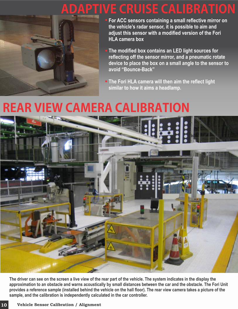
REAR�VIEW�CAMERA�CALIBRATION
The driver can see on the screen a live view of the rear part of the vehicle. The system indicates in the display the approximation to an obstacle and warns acoustically by small distances between the car and the obstacle. The Fori Unit provides a reference sample (installed behind the vehicle on the hall floor). The rear view camera takes a picture of the sample, and the calibration is independently calculated in the car controller.
Vehicle Sensor Calibration / Alignment10

ROLL / BRAKE / DVT SYSTEMS
Windows 7 Embedded based softwareFull featured SPC PackageOn-the Fly customizable softwareHigh speed computer and hardwareComprehensive diagnostics covering all I/O Capability for direct plug-into various vehicle ECU’s via the OBDII connector, and receive/transmit commands Capability for dynamic brake test, free roll testing and DVT testingVarious wheelbase adjustment ranges can be accommodatedVarious horsepower, torque and speed requirements can be accommodatedVarious styles of machine frame architectures can be considered to accommodate pet depths, width and length requirementsDual roller or Single roller design can be offeredSafety retaining rollers, safety stop posts, auto lubrication, auto roller scrapers, and other devices are normally includedOptions for sound proof booths and ventilation systems can be offered
FEATURES
11Roll & Brake / DVT

Roll
Dynamic Brake
4-Wheel Drive
Speed Testing and Speed Calibration
Noise vibration or harness testing
Drag force tests
Wireless dynamic vehicle testing
Cruise control testing
Electrical integration
Transmission shift point Individual wheel testing
Reverse testing
AVAILABLE TESTS
The system software computes brake forceand anti-lock braking system characteristics
Precision speed measurement is attainedwith the use of optical encoders
Preventative maintenance issimplified with the installationof automatic lubricationsystems throughout themachine
Fori's four-roller design cradles and centersthe vehicle on top of the rollers providingsuperior safety, stability and accuracy.
Vehicle Side Guides keep the vehicleon the rollers
12 Roll & Brake / DVT

13Toe Set Tooling Systems
FEATURESTOE SET TOOL SYSTEMS
Decrease in Cycle Time
Reduced Work Force
Increased Accuracy & Repeatability
Increases flexibility by allowing compensation for vehicle
variation, X, Y & Z positioning ,tie rod or cam bolt angle by
vehicle type.
Allows greater gear head access by having programmable
paths versus straight line or fixed cam paths.
Decreases cycle time by having close proximity robot
pounce positions.
Robotic toe set eliminates many valves and actuators
thus reducing downtime.
Can adapt a vision system to locate adjustment points
and compensate robot position.
Tie Rod or cam bolt adjustment
The most popular Fully Automatic Toe Set system is Fori’s patented hex adjustment system. This system incorporates the adjustment and socket into one assembly. The socket is shuttled from one location to the other to perform the appropriate task. Powering the motions of the automation can be pneumatics, electric servo or robot controlled. Fori’s unique compliance in tooling allows for various vehicle variation. Fori offers a full range of Semi & Fully automatic adjustment tools to fit your product. Fori’s tools can be driven pneumatically or electrically, with full integration to the plants torque data verification & storage systems. The motion of the fully automatic toe set system can be air, electric servo, robotic, or a combination.
Fori�has�a�several�patents�for�toe�set�gearhead�advances,�tie�rod�guide�fork�rollers�and�a�single�guide�fork�gearhead�with�a�compliance�locking�brake.

14 Toe Set Tooling Systems
Front and rear robotic toe set can be either a cam bolt style of adjustment or a tie rod style.Adds flexibility by allowing future vehicle types to be added by reprogramming the robot positions.The robot can be coupled with a vision system to first find the tie rod or cam bolt position X, Y & Z and the bolt or tie rod angle then compensate the gear head or nutrunner position when gear head accessibility is very limited. The vision system can also be used to measure Z height or possibly caster.The gear heads can be attached to a robotic quick change adaptor to change the gear heads when adjusting vehicles styles with different hex nuts or cambolts. Can be used with a maintenance retract slide which slides the robot out of position allowing an operator to adjust the tie rod manually. Requires an approximate robot capacity of 120kg.
ROBOTIC�TOE�SET�WITH�VISION�PLACEMENT
Various robot brands and styles can be used. The latest design using the compact series Robot allows the tooling the be stored under the machine frame, to maintain an open architecture. Maintenance slides are not necessary if the tooling must be placed off line.
Specially designed front tooling is provided as the end effecter of the robot. The tooling consists of a gear driven socket that engages with the tie rod adjust hex for setting the toe automatically, then shift to the outer tie rod for engaging with the jamb-nut and securing to the required torque.
The adjustment socket can be controlled by a nut-runner of servomotor. In either case the capability for controlling capability is more improved in comparisons to adjustments done manually with operators.
ROBOTIC FRONT & REAR TOE SET SYSTEMS

15Side Slip Testing
AUDIT�SYSTEMST h e n o n -
contact high speed audit system is de-signed do give the most accurately measured toe , camber & caster values in the market to d a t e . T h i s s y s t e m
utilizes many patented Fori technologies to allow the
plants the fastest and most accurate audit system in the world.
The whole system requires a very shallow pit or the system can use a ramp. A
wide range of wheelbase lengths allows the system to run multiple vehicle styles an a single
machine.
CENTERING�PLATFORMSCentering platforms can be used for a variety of applications including that for stand alone headlamp aiming systems, for use with Driver Assist Calibration equipment, and other vehicle measurements when centering of the vehicle is required.
The platforms contain leveling adjustment to provide a level surface for the vehicle. It also includes front and rear pneumatic centering devices, and vehicle guides.
SIDE�SLIP�TESTING
A system with one plate can be used to measure slip displacement on one side of the vehicle, or a dual plate design can be used in the case LH/RH displacement values are required.
The machines are also capable of measuring the slip on the front axle, and rear axle individually.


![more than 25 years - Fori groupforigroup.com/wp-content/uploads/2016/08/FORI-porocilo... · 2017-11-09 · 4 [ BUSINESS AND SUSTAINBILITY REPORT 2015 ] [ BUSINESS AND SUSTAINBILITY](https://img.pdfslide.us/doc/110x75/5f0cc76c7e708231d43716c9/more-than-25-years-fori-2017-11-09-4-business-and-sustainbility-report-2015.jpg)