Embed Size (px)
Citation preview
129 © 2018 Cengage Learning. All Rights Reserved. May not be scanned, copied or duplicated, or posted to a publicly accessible website, in whole or in part.
Chapter 2
STEADY STATE CONDUCTION
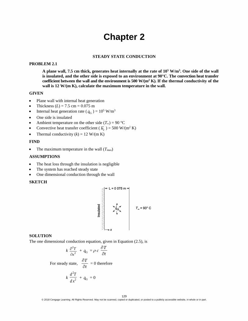
PROBLEM 2.1
A plane wall, 7.5 cm thick, generates heat internally at the rate of 105 W/m3. One side of the wall
is insulated, and the other side is exposed to an environment at 90°C. The convection heat transfer
coefficient between the wall and the environment is 500 W/(m2 K). If the thermal conductivity of the
wall is 12 W/(m K), calculate the maximum temperature in the wall.
GIVEN
Plane wall with internal heat generation
Thickness (L) = 7.5 cm = 0.075 m
Internal heat generation rate (Gq ) = 105 W/m3
One side is insulated
Ambient temperature on the other side (T) = 90 °C
Convective heat transfer coefficient (ch ) = 500 W/(m2 K)
Thermal conductivity (k) = 12 W/(m K)
FIND
The maximum temperature in the wall (Tmax)
ASSUMPTIONS
The heat loss through the insulation is negligible
The system has reached steady state
One dimensional conduction through the wall
SKETCH
SOLUTION
The one dimensional conduction equation, given in Equation (2.5), is
k 2
2
T
x +
Gq = c T
t
For steady state, T
t = 0 therefore
k
2
2
d T
d x +
Gq = 0

130 © 2018 Cengage Learning. All Rights Reserved. May not be scanned, copied or duplicated, or posted to a publicly accessible website, in whole or in part.
2
2
d T
d x = – Gq
k
This is subject to the following boundary conditions
No heat loss through the insulation
d T
d x = 0 at x = 0
Convection at the other surface
– k d T
d x = ch (T – T) at x = L
Integrating the conduction equation once
d T
d x = Gq
k + C1
C1 can be evaluated using the first boundary condition
0 = – Gq
k (0) + C1 C1 = 0
Integrating again
T = – 2
Gq
k x2 + C2
The expression for T and its first derivative can be substituted into the second boundary condition to evaluate
the constant C2
– k Gq L
k = ch
2
22
Gq LC T
k C2 =
Gq L 1
2c
L
kh + T
Substituting this into the expression for T yields the temperature distribution in the wall
T(x) = 2
Gq
k x2 +
Gq L 1
2c
L
kh + T
T(x) = T+ 2
Gq
k
2 22
c
kLL x
h
Examination of this expression reveals that the maximum temperature occurs at x = 0
Tmax = T + 2
Gq
k
2 2
c
kLL
h
Tmax = 90°C +
5 32
2
2[12W/(mK)](0.075m)10 W / m(0.075m)
2[12W/(mK)] 500W/(m K) = 128°C

131 © 2018 Cengage Learning. All Rights Reserved. May not be scanned, copied or duplicated, or posted to a publicly accessible website, in whole or in part.
PROBLEM 2.2
A small dam, which may be idealized by a large slab 1.2 m thick, is to be completely poured in a
short period of time. The hydration of the concrete results in the equivalent of a distributed
source of constant strength of 100 W/m3. If both dam surfaces are at 16°C, determine the
maximum temperature to which the concrete will be subjected, assuming steady-state conditions.
The thermal conductivity of the wet concrete may be taken as 0.84 W/(m K).
GIVEN
Large slab with internal heat generation
Internal heat generation rate (Gq ) = 100 W/m3
Both surface temperatures (Ts) = 16°C
Thermal conductivity (k) = 0.84 W/(m K)
FIND
The maximum temperature (Tmax)
ASSUMPTIONS
Steady state conditions prevail
SKETCH
SOLUTION
The dam is symmetric. Therefore, x will be measured from the centerline of the dam. The equation for one
dimensional conduction is given by Equation (2.5)
k 2
2
T
x +
Gq = c T
t
For steady state, T
t = 0 therefore
k
2
2
d T
d x +
Gq = 0
This is subject to the following boundary conditions
1. By symmetry, dT/dx = 0 at x = o
2. T = Ts at x = L
Also note that for this problem Gq is a constant.
Integrating the conduction equation
132 © 2018 Cengage Learning. All Rights Reserved. May not be scanned, copied or duplicated, or posted to a publicly accessible website, in whole or in part.
d T
d x = – Gq
kx + C1
The constant C1 can be evaluated using the first boundary condition
0 = – Gq
k (0) + C1 C1 = 0
Integrating once again
T = 2
Gq
k x2 + C2
The constant C2 can be evaluated using the second boundary condition
Ts = 2
Gq
k L2 + C2 C2 = Ts +
2
Gq
k L2
Therefore, the temperature distribution in the dam is
T = Ts + 2
Gq
k (L2 – x2)
The maximum temperature occurs at x = 0
Tmax = Ts + 2
Gq
k(L2 – (0)2) = 16°C +
3100W/m
2[0.84W/(m K)] (0.6 m)2 = 37°C
COMMENTS
This problem is simplified significantly by choosing x = 0 at the centerline and taking advantage of the
problem’s symmetry.
For a more complete analysis, the change in thermal conductivity with temperature and moisture content
should be measured. The system could then be analyzed by numerical methods discussed in chapter 4.
133 © 2018 Cengage Learning. All Rights Reserved. May not be scanned, copied or duplicated, or posted to a publicly accessible website, in whole or in part.
PROBLEM 2.3
The shield of a nuclear reactor is idealized by a large 25 cm thick flat plate having a thermal
conductivity of 3.5 W/(m K). Radiation from the interior of the reactor penetrates the shield and
there produces heat generation that decreases exponentially from a value of 187.6 kW/ m3. at the
inner surface to a value of 18.76 kW/m3 at a distance of 12.5 cm from the interior surface. If the
exterior surface is kept at 38°C by forced convection, determine the temperature at the inner
surface of the shield. Hint: First set up the differential equation for a system in which the heat
generation rate varies according to q (x) = q (0)e–Cx.
GIVEN
Large flat plate with non-uniform internal heat generation
Thickness (L) = 25 cm=0.25 m
Thermal conductivity (k) = 3.5 W/(m K)
Exterior surface temperature (To) = 38°C
Heat generation is exponential with values of
187.6 kW/m3 at the inner surface
18.76 kW/m3 at 12.5 cm from the inner surface
FIND
The inner surface temperature (Ti)
ASSUMPTIONS
One dimensional, steady state conduction
The thermal conductivity is constant
No heat transfer at the inner surface of the shield
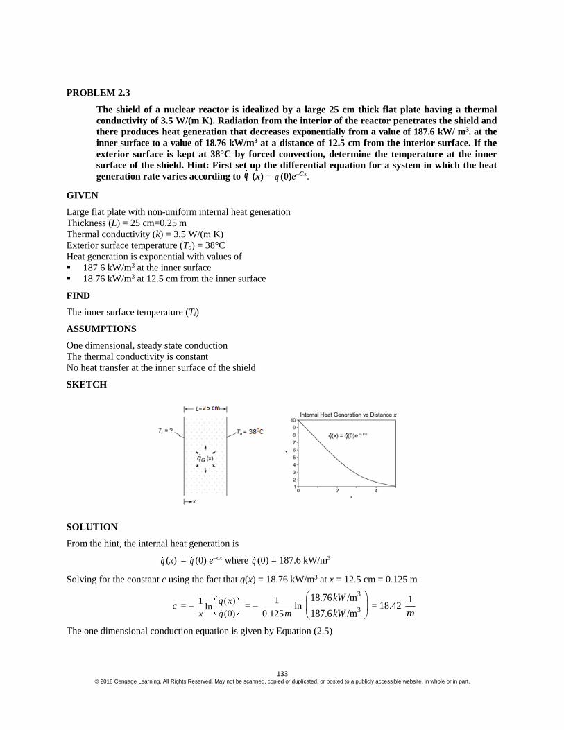
SKETCH
SOLUTION
From the hint, the internal heat generation is
q (x) = q (0) e–cx where q (0) = 187.6 kW/m3
Solving for the constant c using the fact that q(x) = 18.76 kW/m3 at x = 12.5 cm = 0.125 m
c = – 1 ( )
ln(0)
q x
x q = –
1
0.125mln
3
3
18.76 /m
187.6 /m
kW
kW
= 18.42 1
m
The one dimensional conduction equation is given by Equation (2.5)

134 © 2018 Cengage Learning. All Rights Reserved. May not be scanned, copied or duplicated, or posted to a publicly accessible website, in whole or in part.
k 2
2
T
x +
Gq = c T
t = 0 (steady state)
2
2
d T
d x = –
( )Gq x
k =
(0)q
ke–cx
The boundary conditions are
dT
dx = 0 at x = 0
T(L) = To = 100°F at x = L
Integrating the conduction equation
dT
dx = –
(0)q
ck e–cx + C1
The constant C1 can be evaluated by applying the first boundary condition
0 = – (0)q
ck e–c(0) + C1 C1 =
(0)q
ck
Integrating again
T(x) = 2
(0)q
c k e–cx –
2
(0)q
c kx + C2
The constant C2 can be evaluated by applying the second boundary condition
T(L) = To = 2
(0)q
c ke–cL –
(0)q
c k L + C2 C2 = To +
(0) 1 cLqL e
ck c
Therefore, the temperature distribution is
T(x) = To + 2
(0)q
c k [e–cL – e–cx + c(L – x)]
Solving for the temperature at the inside surface (x = 0)
Ti = T(0) = To + 2
(0)q
c k [e–cL – 1 + cL]
Ti = 38°C+
3
2
187600 W /
18.423.5 /(m )
m
W Km
(18.42/ ) 0.25 11 18.42 0.25m me m
m
=38°C+
3
2
187600 W /
18.423.5 /(m )
m
W Km
* 3.615 = 6090C

135 © 2018 Cengage Learning. All Rights Reserved. May not be scanned, copied or duplicated, or posted to a publicly accessible website, in whole or in part.
PROBLEM 2.4
A plane wall 15 cm thick has a thermal conductivity given by the relation
k = 2.0 + 0.0005 T W/(m K)
where T is in degrees Kelvin. If one surface of this wall is maintained at 150 °C and the other at
50 °C, determine the rate of heat transfer per square meter. Sketch the temperature distribution
through the wall.
GIVEN
A plane wall
Thickness (L) = 15 cm = 0.15 m
Thermal conductivity (k) = 2.0 + 0.0005 T W/(m K) (with T in Kelvin)
Surface temperatures: Th = 150 °C Tc = 50 °C
FIND
(a) The rate of heat transfer per square meter (q/A)
(b) The temperature distribution through the wall
ASSUMPTIONS
The wall has reached steady state
Conduction occurs in one dimension
SKETCH
SOLUTION
Simplifying Equation (2.2) for steady state conduction with no internal heat generation but allowing for the
variation of thermal conductivity with temperature yields
d dT
kdx dx
= 0
with boundary conditions: T = 423 K at x = 0
T = 323 K at x = 0.15 m
The rate of heat transfer does not vary with x
– k dT
dx =
q
A = constant
– (2.0 + 0.0005T) dT = q
A dx

136 © 2018 Cengage Learning. All Rights Reserved. May not be scanned, copied or duplicated, or posted to a publicly accessible website, in whole or in part.
Integrating
2.0T + 0.00025 T 2 = – q
A x + C
The constant can be evaluated using the first boundary condition
2.0 (423) + 0.00025 (423)2 = C – q
A (0) C = 890.7
(a) The rate of heat transfer can be evaluated using the second boundary condition:
2.0 (323) + 0.00025 (323)2 = 890.7 – q
A (0.15 m) q
k = 1457 W/m2
(b) Therefore, the temperature distribution is
0.00025 T 2 + 2.0 T = 890.7 – 1458 x
COMMENTS
Notice that although the temperature distribution is not linear due to the variation of the thermal conductivity
with temperature, it is nearly linear because this variation is small compared to the value of the thermal
conductivity.
If the variation of thermal conductivity with temperature had been neglected, the rate of heat transfer would
have been 1333 W/m2, an error of 8.5%.

137 © 2018 Cengage Learning. All Rights Reserved. May not be scanned, copied or duplicated, or posted to a publicly accessible website, in whole or in part.
PROBLEM 2.5
Derive an expression for the temperature distribution in a plane wall in which there are
uniformly distributed heat sources that vary according to the linear relation
Gq =
wq [1 – (T – Tw)]
where qw is a constant equal to the heat generation per unit volume at the wall temperature Tw.
Both sides of the plate are maintained at Tw and the plate thickness is 2L.
GIVEN
A plane wall with uniformly distributed heat sources as in the above equation
Both surface temperatures = Tw
Thickness = 2L
FIND
An expression for the temperature distribution
ASSUMPTIONS
Constant thermal conductivity (k)
SKETCH
SOLUTION
The equation for one dimensional, steady state (dT/dt = 0) conduction from Equation (2.5) is
2
2
d T
dx = Gq
k = wq
k [1 – (T – Tw)] = wq
k (T – Tw) – wq
k
With the boundary conditions
dT
dx = 0 at x = 0
T = Tw at x = L
Let = T – Tw and m2 = ( wq )/k then
2
2
d
dx – m2 = wq
k
This is a second order, linear, nonhomogeneous differential equation with constant coefficients. Its solution is
the addition of the homogeneous solution and a particular solution. The solution to the homogeneous equation
2
2
d
dx – m2 = 0

138 © 2018 Cengage Learning. All Rights Reserved. May not be scanned, copied or duplicated, or posted to a publicly accessible website, in whole or in part.
is determined by its characteristics equation. Substituting = ex and its derivatives into the homogeneous
equation yields the characteristics equation
2 ex – m2 ex = 0 = m
Therefore, the homogeneous solution has the form
h = C1 cmx + C2 e
–mx
A particular solution for this problem is simply a constant: = ao
Substituting this into the differential equation
0 – m2 ao = wq
k ao =
2
wq
m k
Therefore, the general solution is
= C1 emx + C2 e–mx +
2
wq
m k
With the boundary condition
d
dx = 0 at x = 0
= 0 at x = L
Applying the first boundary condition:
d
dx = C1 me(0) – C2 me(0) = 0 C1 = C2 = C
From the second boundary condition
0 = C (emL + e–mL) + 2
wq
m k C =
2 ( )
w
mL mL
q
m k e e
The temperature distribution in the wall is
= T(x) – Tw = 2 ( )
w
mL mL
q
m k e e (emx + e–mx) +
2
wq
m k
T(x) = Tw + 2
wq
m k1
mx mx
mL mL
e e
e e
T(x) = Tw + 2
wq
m k
cosh( )1
cosh( )
mx
mL

139 © 2018 Cengage Learning. All Rights Reserved. May not be scanned, copied or duplicated, or posted to a publicly accessible website, in whole or in part.
PROBLEM 2.6
A plane wall of thickness 2L has internal heat sources whose strength varies according to
Gq =
0q cos (ax)
where 0q is the heat generated per unit volume at the center of the wall (x = 0) and a is a
constant. If both sides of the wall are maintained at a constant temperature of Tw, derive an
expression for the total heat loss from the wall per unit surface area.
GIVEN
A plane wall with internal heat sources
Heat source strength: Gq =
0q cos (ax)
Wall surface temperatures = Tw
Wall thickness = 2L
FIND
An expression for the total heat loss per unit area (q/A)
ASSUMPTIONS
Steady state conditions prevail
The thermal conductivity of the wall (k) is constant
One dimensional conduction within the wall
SKETCH
SOLUTION
Equation (2.5) gives the equation for one dimensional conduction. For steady state, dT/dt = 0, therefore
2
2 G
Tk q
x = c
T
t = 0
2
2
d T
d x = Gq
k = 0 cos( )q ax
k
With boundary conditions:
dT
dx = 0 at x = 0 (by symmetry)
T = Tw at x = L (given)

140 © 2018 Cengage Learning. All Rights Reserved. May not be scanned, copied or duplicated, or posted to a publicly accessible website, in whole or in part.
Integrating the conduction equation once
dT
dx = - oq
a k sin (ax) + C1
Applying the first boundary condition yields: C1 = 0
The rate of heat transfer from one side of the wall is
qk = – k A
dT
dx|x = L
= – k A sin( ) sin( )G oq q AaL aL
ak a
The total rate of heat transfer is twice the rate of heat transfer from one side of the wall
total
kq
A =
2 oq
asin (aL)
An alternative method of solution for this problem involves recognizing that at steady state the rate of heat
generation within the entire wall must equal the rate of heat transfer from the wall surfaces
A ( )L
GLq x dx = q
oq cos
L
L(ax) dx =
q
A
sin( ) sin( )oqaL aL
a =
q
A
q
A =
2 oq
asin (aL)
COMMENTS
The heat loss can be determined by solving for the temperature distribution and then the rate of heat transfer or
via the conservation of energy which allows us to equate the heat generation rate with the rate of heat loss.

141 © 2018 Cengage Learning. All Rights Reserved. May not be scanned, copied or duplicated, or posted to a publicly accessible website, in whole or in part.
PROBLEM 2.7
A very thin silicon chip is bonded to a 6-mm thick aluminum substrate by a 0.02-mm thick epoxy
glue. Both surfaces of this chip-aluminum system are cooled by air at 250C, where the convective heat
transfer coefficient of air flow is 100 W/(m2 K). If the heat dissipation per unit area from the chip is
104 W/m2 under steady state condition, draw the thermal circuit for the system and determine the
operating temperature of the chip.
GIVEN
Silicon chip bonded to 6-mm thick aluminum substrate bye 0.02-mm thick epoxy glue
Air temperature(T∞)=250C
Convective heat transfer coefficient(h̅)=100 W/(m2 K)
Heat dissipation from chip(q/A)= 104 W/m2
FIND
Draw thermal circuit of system
Operating temperature of the chip.
ASSUMPTIONS
1-Dimensional Steady state conditions prevail
Negligible heat loss from the sides
Isothermal chip
Negliglble radiation
SKETCH
SOLUTION
From the figure
Total heat transferred to the surrounding is sum of heat transferred from upper surface and lower
surface. Thus
.
q =.
1q +.
2q
.
q =2
1 1
1 1 ( / )
c c
e a
e a
T T T T K
L L m K W
h h k k

142 © 2018 Cengage Learning. All Rights Reserved. May not be scanned, copied or duplicated, or posted to a publicly accessible website, in whole or in part.
.
q = 3 5 24
298
1 6*10 10 ( / )10
1000 1644 50
c cT K T T K
m K W
= 104 W/m2
104 =
4 4
4 4
201.36*10 ( 298) 10 *10( 298)
2513.6*10 *10
c cT T
2513.6+62985.28=211.36*Tc
Tc=310 K
COMMENT
The heat transfer occurs on both sides through the chip to the surrounding. As there are both conductive and
convective resistances on the lower side heat flow rate on the lower side will be less than that on the upper side
which has only convective resistance.

143 © 2018 Cengage Learning. All Rights Reserved. May not be scanned, copied or duplicated, or posted to a publicly accessible website, in whole or in part.
PROBLEM 2.8
A thin, flat plate integrated circuit of 5 mm thickness is cooled on its upper surface by a dielectric
liquid. The heat dissipation rate from the chip is 20,000 W/m2 and with the coolant flow at a free
stream temperature of T∞,l =250C, the convective heat transfer coefficient between the chip surface
and the liquid is 1000 W/(m2 K). On the lower surface, the chip is attached to a circuit board, where
the thermal contact resistance between the chip and the board is 10-4 m2.K/W. The thermal
conductivity of board material is 1.0 W/m. K, and its other surface ( away from the chip) is exposed
to ambient air at T∞,a =200C where it is cooled by natural convection with the heat transfer coefficient
of 30 W/(m2 K). (a) Determine the chip surface temperature under steady state condition for the
described conditions. (b) If the maximum chip temperature is not to exceed 750C, determine
maximum allowable heat flux that is generated by the chip. (c) A colleague suggests that in order to
improve the cooling, you use a high conductivity bonding base at chip-board interface that would
reduce the thermal contact resistance at the interface to 10-5 m2.K/W. Determine the consequent
increase in the chip heat flux that can be sustained.
GIVEN
Heat dissipation rate ( q )= 20,000 W/m2
Coolant free stream temp (T∞,l)= 250C
Ambient air temperature (T∞,a)= 200C
Heat transfer coefficient (h̅)= 1000 W/(m2 K)
Thermal contact resistance (R”tc) =10-4 m2.K/W
Maximum chip temperature=750C
FIND
(a) Chip surface temperature under steady state condition
(b) Maximum allowable heat flux generated by the chip
(c) Consequent increase in chip heat flux if high conductivity bonding is used.
ASSUMPTIONS
Steady state conditions prevail
The thermal conductivity of the wall (k) is constant
One dimensional conduction
Negligible radiation and thermal resistance between chip surface and the liquid.
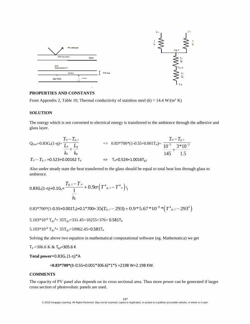
SKETCH
The thermal circuit of problem is given by
SOLUTION
(a) A heat balance in the above problem gives
.
q =.
liquidq +.
airq
Substituting values from thermal circuits

144 © 2018 Cengage Learning. All Rights Reserved. May not be scanned, copied or duplicated, or posted to a publicly accessible website, in whole or in part.
20000 W/m2=2
298
1 1 0.005 ( / )0.0001
1000 30 1
c cT K T T K
m K W
20000 W/m2=( 298cT )*1000 + ( 293cT )/0.03843 W/m2
20000 W/m2=(1000Tc-298000+26.01Tc-7620.93) W/m2
Solving for Tc , we get Tc = 317.63 K or 44.37 0C
(b) Tc,max=750C= 343 K Solving for q from above equation, we get
Q=50*1000+ 55*26.01 W/m2
=50000+1430.55 W/m2
=5.14*104 W/m2
(c) Using the same equation as in (a), and changing only the value of thermal resistance, and using
the value of Tc as 343 K, we get q=4.63*104 W/m2, which is a decrease in allowable heat dissipation
of around 5126 W/m2.

145 © 2018 Cengage Learning. All Rights Reserved. May not be scanned, copied or duplicated, or posted to a publicly accessible website, in whole or in part.
PROBLEM 2.9
In a large chemical factory, hot gases at 2273 K are cooled by a liquid at 373 K with gas side and liquid side
convection heat transfer coefficients of 50 and 1000 W/(m2 K), respectively. The wall that separates the gas
and liquid streams is composed of 2-cm thick slab of stainless steel on the liquid side. There is a contact
resistance between the oxide layer and the steel of 0.05 m2.K/W. Determine the rate of heat loss from hot
gases through the composite wall to the liquid.
GIVEN
Hot gases at Tg=2273 K cooled by liquid at Tf=373 K
Convection heat transfer coefficients on gas side h̅g=50 W/(m2 K) and h̅f=100 W/(m2 K)
Wall of stainless steel of thickness(L)= 2 cm = 0.02 m
Contact resistance (Rcr”)= 0.05 m2.K/W
FIND
Rate of heat loss from hot gases through composite wall to liquid.
ASSUMPTIONS
1 Dimensional steady state heat transfer
Thermal conductivity remain constant.
Radiation is negligible.
SKETCH
PROPERTIES AND CONSTANTS
From Appendix 2, Table 10, Thermal conductivity of stainless steel (k) = 14.4 W/(m2 K)
SOLUTION
Total resistance for the heat flow through the pipe is given by
Rtotal=1 1
"cr
f g
LR
h k h m2.K/W
=1 0.02 1
0.0550 14.4 100
m2.K/W
=0.02+0.05+0.0014+0.01 m2.K/W
=0.0814 m2.K/W
Heat flux for the above resistance for given temperature difference is given by
q = g f totalT T R W/m2
= 2273 373 0.0814 W/m2 =23342 W/m2

146 © 2018 Cengage Learning. All Rights Reserved. May not be scanned, copied or duplicated, or posted to a publicly accessible website, in whole or in part.
PROBLEM 2.10
The conversion of solar energy into electric power by means of photovoltaic panels will be an important part
of the transition from fossil fuels to sustainable energy resources. As described in detail in Principles of
Sustainable Energy, a typical PV panel consists of a top layer of glass attached with a thin optically clear
adhesive to a very thin layer of photoelectric material such as doped-silicon in which the incident solar
irradiation is converted into electric energy. Experiments have shown that the solar to electric efficiency
ƞ=0.55-0.001Tsilicon, where Tsilicon is the silicon temperature in K. In a typical installation where solar
irradiation is G=700 W/m2, 7% is reflected from the top surface of the glass, 10% is absorbed by the glass,
and 83% is transmitted to the photovoltaic active layer. A part of irradiation absorbed by photovoltaic
material is converted into heat and the remainder is converted into electric energy. The silicon layer is
attached by a 0.01-mm thick layer of solder to a 3-mm thick aluminum nitride substrate as shown in the
schemetic. Determine the electric power produced by this PV panel, assuming the following properties for
the pertinent materials: conductivity of the glass kg=1.4 W/(m K), conductivity of the adhesive ka=145 W/(m
K), the emmisivity of the glass is 0.90, heat transfer coefficient from the top of the panel to the surrounding is
35 W/(m2 K), and the surrounding air temperature is Tair=200C. The solar PV panel is 5 m long and 1 m wide
and is situated on the roof where the bottom is considered insulated. (Hint: Start by applying first law of
thermodynamics to the photovoltaic-active layer and note that some of the irradiation will be converted to
electricity and some of it transmitted thermally).
GIVEN
Electric efficiency ƞ=0.55-0.001Tsilicon
Solar irradiation is G=700 W/m2
Thickness of solder(ts=0.01 mm
Al substrate thickness (tAl)=3 mm=0.003 m
Conductivity of the glass kg=1.4 W/(m K)
Conductivity of the adhesive ka=145 W/(m K)
Emissivity of the glass is 0.90
Heat transfer coefficient from the top of the panel to the surrounding(hc)= 35 W/(m2 K),
Surrounding air temperature is Tair=200C.
Solar PV panel area= 5 m*1m
FIND
Electric power produced by the PV panel.
ASSUMPTIONS
1 Dimensional steady state heat transfer
Thermal conductivity remains constant.
SKETCH
147 © 2018 Cengage Learning. All Rights Reserved. May not be scanned, copied or duplicated, or posted to a publicly accessible website, in whole or in part.
PROPERTIES AND CONSTANTS
From Appendix 2, Table 10, Thermal conductivity of stainless steel (k) = 14.4 W/(m2 K)
SOLUTION
The energy which is not converted to electrical energy is transferred to the ambience through the adhesive and
glass layer.
Qloss=0.83Gs(1-ƞ)=,si g t
a g
a g
T T
L L
k k
=> 0.83*700*(1-0.55+0.001Tsi)=
,
5 310 3*10
145 1.5
si g tT T
,si g tT T =0.523+0.00162 Tsi => Tsi=0.524+1.0016Tg,t
Also under steady state the heat transferred to the glass should be equal to total heat loss through glass to
ambience.
0.83Gs(1-ƞ)+0.1Gs= , 4 4
,0.91
g tg t
c
T TT T
h
\
0.83*700*(1-0.55+0.001Tsi)+0.1*700= 8 4 4, ,35( 293) 0.9*5.67*10 * 293g t g tT T
5.103*10-8 Tg,t4+ 35Tg,t=331.45+10255+376+ 0.581Tsi
5.103*10-8 Tg,t4+ 35Tg,t=10962.45+0.581Tsi
Solving the above two equation in mathematical computational software (eg. Mathematica) we get
Tsi =306.6 K & Tg,t=305.6 K
Total power=0.83Gs (1-ƞ)*A
=0.83*700*(1-0.55+0.001*306.6)*1*5 =2198 W=2.198 KW.
COMMENTS
The capacity of PV panel also depends on its cross sectional area. Thus more power can be generated if larger
cross section of photovoltaic panels are used.

148 © 2018 Cengage Learning. All Rights Reserved. May not be scanned, copied or duplicated, or posted to a publicly accessible website, in whole or in part.
149 © 2018 Cengage Learning. All Rights Reserved. May not be scanned, copied or duplicated, or posted to a publicly accessible website, in whole or in part.
PROBLEM 2.11
For the design of novel type of nuclear power plant, it is necessary to determine the temperature distribution
in a large slab-type nuclear fuel element. Volumetric heat is generated uniformly in the fuel element at the
rate of 2*107 W/m3. This slab fuel is insulated on one side, while on other side it is covered by a stainless steel
cladding of 0.3 cm thickness. Heat is removed from the fuel slab by a liquid at 2000C that flows on the other
side of the steel cladding with the convective heat transfer coefficient of 10,000 W/(m2 K). Determine the
maximum temperature in the fuel element and sketch the temperature distribution.
GIVEN
Volumetric heat generated ( q )=2*107 W/m2
Stainless steel cladding thickness (y)= 0.3 cm = 0.003 m
Coolant liquid temperature (T∞)= 2000C
Heat transfer coefficient(h̅)= 1000 W/(m2 K)
Fuel element thickness (x)=1.5 cm = 0.015 m
FIND
Maximum temperature in fuel element
Sketch temperature distribution.
ASSUMPTIONS
1 Dimensional steady state heat transfer
Constant properties.
Uniform heat generation.
Negligible contact resistance between surfaces.
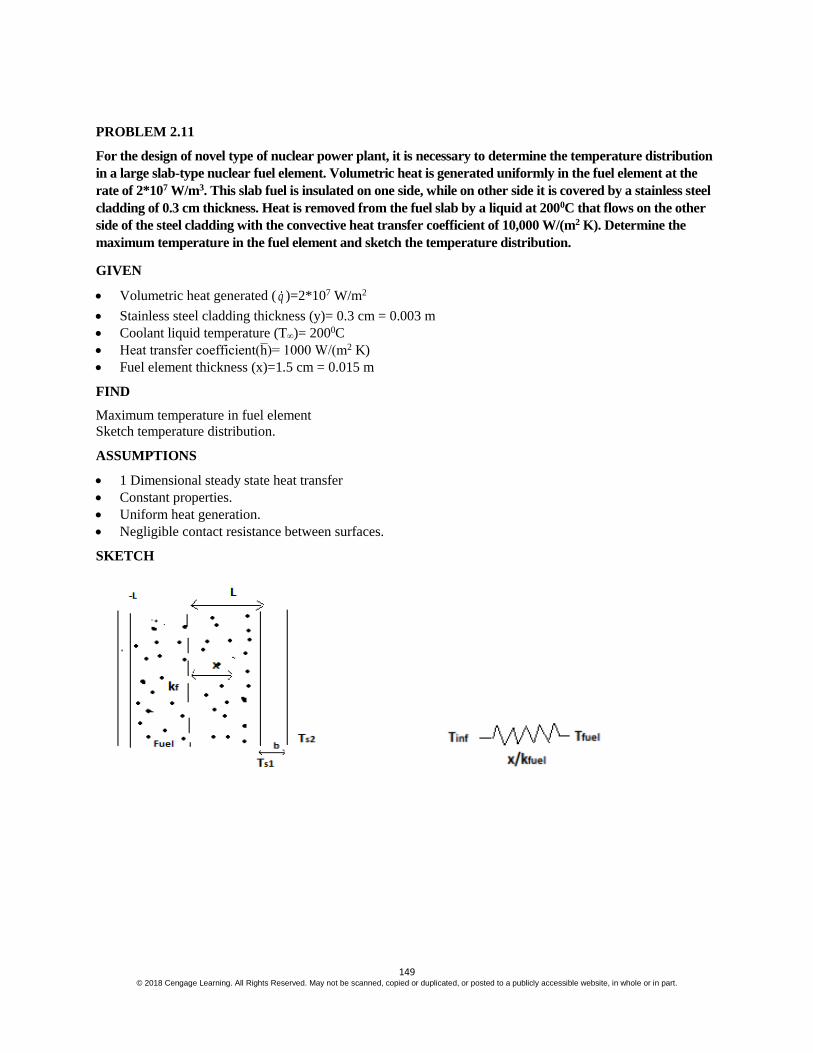
SKETCH
150 © 2018 Cengage Learning. All Rights Reserved. May not be scanned, copied or duplicated, or posted to a publicly accessible website, in whole or in part.
PROPERTIES AND CONSTANTS
From Appendix 2, Table 10, Thermal conductivity of stainless steel (k) = 14.4 W/(m2 K)
SOLUTION
Heat transfer equation in 1 dimension with steady state and uniform heat generation is given by
2
20
f
T q
x k
where x varies from –L to L

151 © 2018 Cengage Learning. All Rights Reserved. May not be scanned, copied or duplicated, or posted to a publicly accessible website, in whole or in part.
Integrating twice we get
1
f
dT qx C
dx k and
21 2
2 f
qT x C x C
k where C1 and C2 are constants.
Applying boundary conditions
1. The wall is insulated at the end thus q (x=-L)=0 ( which implies dT
dx=0)
Substituting this in first order equation above we get
1
)
( )(x L f
dT qL C
dx k
1
f
qC L
k
2. Using energy conservation equation
q conduction= q convection
q conduction equation considering unit width q (2L)= 1 2s
s sk
T Tb
q convection equation is 1 2 2s
s s sk
T T h T Tb
Equating these two above equations at L we get
T(L)=Ts1=(2 ) (2 )
s
q Lb q LT
k h
The differential equation at x=L gives
Tx=L= 2 22
2 f f
q qL L C
k k
Equating both and solving for C2 we get
C2=2 2 3
s f
b LT qL
k h k
Substituting C1 and C2 in the integrated differential equation we get
2 2 2 3
2 2f f s f
q q b LT x Lx T qL
k k k h k
Tmax occurs at 0dT
dx

152 © 2018 Cengage Learning. All Rights Reserved. May not be scanned, copied or duplicated, or posted to a publicly accessible website, in whole or in part.
Applying this condition in differential equation above we get
0f f
q qx L
k k which implies Tmax is at –L. Thus
Tmax=2 2 2 3
2 2f s f
q b LL T qL
k k h k
Substituting values to get Tmax we get
Tmax=7 3 3
3 2 7 32*10 2*3*10 2 3*7.5*10(7.5*10 ) 2*10 *7.5*10
2*60 14.4 10000 2*60T
Tmax=9.375+200+55.63 K
= 265 K

153 © 2018 Cengage Learning. All Rights Reserved. May not be scanned, copied or duplicated, or posted to a publicly accessible website, in whole or in part.
PROBLEM 2.12
Nomads in the desert make ice by exposing a thin water layer to cold air during the night. The icing or
freezing of thin layers of water is often also referred to as ice making by nocturnal ( or night time ) cooling,
where the surface temperature of water is lowered considerably by radioactive and convective cooling, and it
had been practiced extensively in ancient India. To model this process and evaluate the conduction process in
water layer, consider a 5-mm thick horizontal layer gets cooled such that its top surface is at temperature of -
50C. After a while the water begins to freeze at top surface and the ice front expands downwards through the
water layer. Determine the location of solid liquid(ice-water) interface if the bottom surface temperature of
the liquid water is at 30C. State your assumptions for the model and calculations.
GIVEN
Thickness of the layer(t)= 5 mm
Surface temperature (Ts)= -50C=268 K
Water temperature(Tw)= 30C= 276 K
FIND
Location of solid liquid interface .
ASSUMPTIONS
1 Dimensional steady state heat transfer
Constant properties throughout time
Negligible radiation
Negligible convection by liquid.
SKETCH
PROPERTIES AND CONSTANTS
From Appendix 2, Table 10,
For water at 273 K, kw=0.569 W/mK
For ice at 273 K, ki=1.88 W/mK
SOLUTION
If x is the distance of solid liquid interface from liquid surface, the energy balance over the interface gives
*( 273) *(273 )
5
w w i sk T k T
x x
=>
0.569*(276 273) 1.88*(273 268)
5x x
Solving for x we get
1.707(5-x) = 9.4 x => x=0.77 mm
Thus the interface is at distance of 0.77 mm from liquid surface or 4.23 mm from ice surface.

154 © 2018 Cengage Learning. All Rights Reserved. May not be scanned, copied or duplicated, or posted to a publicly accessible website, in whole or in part.
STEADY STATE CONDUCTION IN CYLINDERS
PROBLEM 2.13
The heat conduction equation in cylindrical coordinates is
c T
t = k
2 2 2
2 2 2 2
1 1T T T T
r rr r z+q˙G
(a) Simplify this equation by eliminating terms equal to zero for the case of steady-state heat flow
without sources or sinks around a right-angle corner such as the one in the accompanying
sketch. It may be assumed that the corner extends to infinity in the direction perpendicular to
the page. (b) Solve the resulting equation for the temperature distribution by substituting the
boundary condition. (c) Determine the rate of heat flow from T1 to T2. Assume k = 1 W/(m K)
and unit depth .
GIVEN
Steady state conditions
Right-angle corner as shown below
No sources or sinks
Thermal conductivity (k) = 1 W/(m K)
FIND
(a) Simplified heat conduction equation
(b) Solution for the temperature distribution
(c) Rate of heat flow from T1 to T2
ASSUMPTIONS
Corner extends to infinity perpendicular to the paper
No heat transfer in the z direction
Heat transfer through the insulation is negligible
SKETCH
SOLUTION
The boundaries of the region are given by
1 m r 2 m
0 2

155 © 2018 Cengage Learning. All Rights Reserved. May not be scanned, copied or duplicated, or posted to a publicly accessible website, in whole or in part.
Assuming there is no heat transfer through the insulation, the boundary condition is
T
r = 0 at r = 1 m
T
r = 0 at r = 2 m
T1 = 100°C at = 0
T2 = 0°C at = 2
(a) The conduction equation is simplified by the following
Steady state
T
t = 0
No sources or sinks
qk = 0
No heat transfer in the z direction
2
2
T
z = 0
Since T
r = 0 over both boundaries,
T
r = 0 throughout the region
(Maximum principle); therefore, 2
2
T
r = 0 throughout the region also.
Substituting these simplifications into the conduction equation
0 = k
2
2 2
10 0 0
T
r
2
2
T = 0
(b) Integrating twice
T = c1 + c2
The boundary condition can be used to evaluate the constants
At = 0, T = 100°C : 100°C = c2
At = 2
, T = 0°C : 0°C = c1 (/2) + 100°C
c1 = –o200 C
Therefore, the temperature distribution is

156 © 2018 Cengage Learning. All Rights Reserved. May not be scanned, copied or duplicated, or posted to a publicly accessible website, in whole or in part.
T() = 100 – 200 C
°C
(c) Consider a slice of the corner as follow
The heat transfer flux through the shaded element in the direction is
q= thickness
k T =
( )k T T
r
In the limit as 0, q= – k dT
r d
Multiplying by the surface area drdz and integrating along the radius
q = 1
or
rq drdz =
200°C k
1
or
r
dr
r =
200°C k ln
1
or
r
q = 200°C k
[1 W/(m K)] ln(2 m/1 m) = 44.1 W/m 44.1W per meter in the z direction
COMMENTS
Due to the boundary conditions, the heat flux direction is normal to radial lines.

157 © 2018 Cengage Learning. All Rights Reserved. May not be scanned, copied or duplicated, or posted to a publicly accessible website, in whole or in part.
PROBLEM 2.14
Calculate the rate of heat loss per foot and the thermal resistance for a 15 cm schedule 40 steel
pipe covered with a 7.5 cm thick layer of 85% magnesia. Superheated steam at 150°C flows
inside the pipe [ch = 170 W/(m2 K)] and still air at 16°C is on the outside
[ch = 30 W/(m2 K)].
GIVEN
A 6 in. standard steel pipe covered with 85% magnesia
Magnesia thickness = 15 cm=0.15 m
Superheated steam at Ts= 150°C flows inside the pipe
Surrounding air temperature (T) = 17°C
Heat transfer coefficients
Inside (cih ) = 170 W/(m2 K)
Outside (coh ) = 30 W/(m2 K)
FIND
(a) The thermal resistance (R)
(b) The rate of heat loss per foot (q/L)
ASSUMPTIONS
Constant thermal conductivity
The pipe is made of 1% carbon steel
SKETCH
PROPERTIES AND CONSTANTS
From Appendix 2, Tables 10, 11, and 41
For a 6 in. schedule 40 pipe
Inside diameter (Di) = 6.065 in.=0.154 m
Outside diameter (Do) = 6.625 in.=0.1683 m
Thermal Conductivities
85% Magnesia (kI) = 0.059 W/(m K) at 20°C
1% Carbon steel (ks) = 43 W/(m K) at 20°C
SOLUTION
The thermal circuit for the insulated pipe is shown below

158 © 2018 Cengage Learning. All Rights Reserved. May not be scanned, copied or duplicated, or posted to a publicly accessible website, in whole or in part.
(a) The values of the individual resistances can be calculated using Equations (1.14) and (2.39)
Rco = 1 1
co o co ih A h D L =
2
1 1
[30 /(m )] 0.1683 0.075 * LW K m L
0.04361 (m K)/W
RkI =
ln
2
i
o
i
r
r
L k =
2
(0.1683 0.075)ln
0.1683
2 * *0.059 /(m K)
m
m
L W
= 1
L 0.9942 (m K)/W
Rks =
ln
2
o
i
s
r
r
L k =
0.1683ln
0.154
2 * 43 /( )W m K
=
1
L 0.000329 (m K)/W
Rci = 1
ci ih A =
1
ci ih D L =
2
1
[170 /(m )] 0.154W K L =
1
L 0.01216 (m K)/W
The total resistance is
Rtotal = Rco + RkI + Rks + Rci
Rtotal = 1
L (0.04361+ 0.9942 + 0.00329 + 0.01216) (m K)/W
Rtotal = 1
L 1.05326 (m K)/W
(b) The rate of heat transfer is given by
q = total
T
R =
150° 17°
11.05326 ( )/W
C C
mKL
q
L = 126.27 W/m
COMMENTS
Note that almost all of the thermal resistance is due to the insulation and that the thermal resistance of the steel
pipe is negligible.

159 © 2018 Cengage Learning. All Rights Reserved. May not be scanned, copied or duplicated, or posted to a publicly accessible website, in whole or in part.
PROBLEM 2.15
Suppose that a pipe carrying a hot fluid with an external temperature of Ti and outer radius ri is
to be insulated with an insulation material of thermal conductivity k and outer radius ro. Show
that if the convective heat transfer coefficient on the outside of the insulation is h and the
environmental temperature is T, the addition of insulation can actually increases the rate of
heat loss if ro < k / h and that maximum heat loss occurs when ro = k/ h . This radius, rc, is often
called the critical radius.
GIVEN
An insulated pipe
External temperature of the pipe = Ti
Outer radius of the pipe = ri
Outer radius of insulation = ro
Thermal conductivity = k
Ambient temperature = T
Convective heat transfer coefficient = h
FIND
Show that
(a) The insulation can increase the heat loss if ro < k/ h
(b) Maximum heat loss occurs when ro = k/ h
ASSUMPTIONS
The system has reached steady state
The thermal conductivity does not vary appreciably with temperature
Conduction occurs in the radial direction only
SKETCH
SOLUTION
Radial conduction for a cylinder of length L is given by Equation (2.37)
qk = 2 L k
0ln
i o
i
T T
r r
Convection from the outer surface of the cylinder is given by Equation (1.10)
qc
= ch A T = h 2 ro L (To – T)
For steady state qk
= qc
2 L k 0ln
i o
i
T T
r r
= h 2 ro L (To – T)

160 © 2018 Cengage Learning. All Rights Reserved. May not be scanned, copied or duplicated, or posted to a publicly accessible website, in whole or in part.
The outer wall temperature, To, is an unknown and must be eliminated from the equation
Solving for Ti – To
Ti – To = oh r
k ln o
i
r
r (To – T)
Ti – T = (Ti – To) + (To – T) = oh r
k ln o
i
r
r (To – T) + (To – T)
Ti – T = ln 1o o
i
h r r
k r (To – T)
or To – T =
1 ln
i
o o
i
T T
h r r
k r
Substituting this into the convection equation
q= qc = h 2 ro L
1 ln
i
o o
i
T T
h r r
k r
=> q= ln1
22
o
i
i
r
r
o
T T
Lkr L h
Examining the above equation, the heat transfer rate is a maximum when the term
ln1
22
o
i
r
r
o Lkr L h is a minimum, which occurs when its differential with respect to ro is zero
1
ln2
o
i
r
ro o
d k
k L dr r h = 0 =>
1
o o
k d
dr rh + ln o
i
r
ro
d
dr= 0
2
1
o
k
h r +
1
or = 0 => ro=
k
h
The second derivative of the denominator is
3
2
o
k
h r –
2
1
or
which is greater than zero at ro = k/h, therefore ro = k/h is a true minimum and the maximum heat loss occurs
when the diameter is ro = k/h. Adding insulation to a pipe with a radius less than k/h will increase the heat loss
until the radius of k/h is reached.
COMMENTS
A more detailed solution taking into account the dependence of hc on the temperature has been obtained by
Sparrow and Kang, Int. J. Heat Mass Transf., 28: 2049–2060, 1985.

161 © 2018 Cengage Learning. All Rights Reserved. May not be scanned, copied or duplicated, or posted to a publicly accessible website, in whole or in part.
PROBLEM 2.16
A solution with a boiling point of 82°C boils on the outside of a 2.5 cm tube with a No. 14 BWG
gauge wall. On the inside of the tube flows saturated steam at 40 kPa(abs). The convection heat
transfer coefficients are 8.5 kW/(m2 K) on the steam side and 6.2 kW/(m2 K) on the exterior
surface. Calculate the increase in the rate of heat transfer if a copper tube is used instead of a
steel tube.
GIVEN
Tube with saturated steam on the inside and solution boiling at 82°C outside
Tube specification: 1 in. No. 14 BWG gauge wall
Saturated steam in the pipe is at 40 kPa(abs)
Convective heat transfer coefficients
Steam side (cih ) : 8.5 kW/(m2 K)
Exterior surface (coh ) : 6.2 kW/(m2 K)
FIND
The increase in the rate of heat transfer for a copper over a steel tube
ASSUMPTIONS
The system is in steady state
Constant thermal conductivities
SKETCH
PROPERTIES AND CONSTANTS:
From Appendix 2, Tables 10, 12, 13 and 42
Temperature of saturated steam at 60 psia (Ts) = 144°C
Thermal conductivities
Copper (kc) = 391 W/(m K) at 127°C
1% Carbon steel (ks) = 43 W/(m K) at 20°C
Tube inside diameter (Di) = 0.0212 m
SOLUTION
The thermal circuit for the tube is shown below
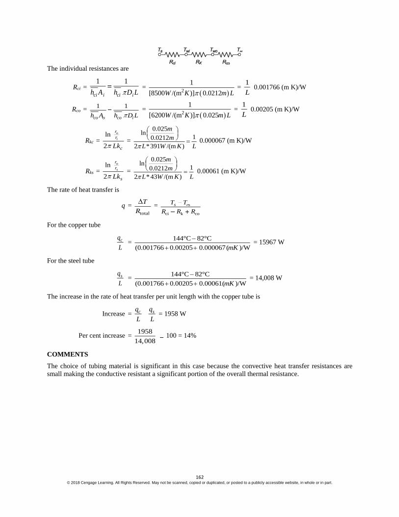
162 © 2018 Cengage Learning. All Rights Reserved. May not be scanned, copied or duplicated, or posted to a publicly accessible website, in whole or in part.
The individual resistances are
Rci = 1 1
ci i ci ih A h D L =
2
1
[8500 /(m )] 0.0212W K m L =
1
L 0.001766 (m K)/W
Rco = 1 1
co o co ih A h D L =
2
1
[6200 /(m )] 0.025W K m L =
1
L 0.00205 (m K)/W
Rkc = ln
2
o
i
r
r
cLk =
0.025ln
10.0212
2 *391 /(m )
m
m
L W K L
0.000067 (m K)/W
Rks = ln
2
o
s
r
r
sLk =
0.025ln
10.0212
2 * 43 /(m )
m
m
L W K L
0.00061 (m K)/W
The rate of heat transfer is
q = total
T
R =
ci k co
sT T
R R R
For the copper tube
cq
L =
144°C 82°C
(0.001766 0.00205 0.000067( )/WmK
= 15967 W
For the steel tube
sq
L =
144°C 82°C
(0.001766 0.00205 0.00061( )/WmK
= 14,008 W
The increase in the rate of heat transfer per unit length with the copper tube is
Increase = c sq q
L L = 1958 W
Per cent increase = 1958
14,008 100 = 14%
COMMENTS
The choice of tubing material is significant in this case because the convective heat transfer resistances are
small making the conductive resistant a significant portion of the overall thermal resistance.

163 © 2018 Cengage Learning. All Rights Reserved. May not be scanned, copied or duplicated, or posted to a publicly accessible website, in whole or in part.
PROBLEM 2.17
Steam having a quality of 98% at a pressure of 1.37 105 N/m2 is flowing at a velocity of 1 m/s
through a steel pipe of 2.7 cm OD and 2.1 cm ID. The heat transfer coefficient at the inner
surface, where condensation occurs, is 567 W/(m2 K). A dirt film at the inner surface adds a unit
thermal resistance of 0.18 (m2 K)/W. Estimate the rate of heat loss per meter length of pipe if; (a)
the pipe is bare, (b) the pipe is covered with a 5 cm layer of 85% magnesia insulation. For both
cases assume that the convective heat transfer coefficient at the outer surface is 11 W/(m2 K) and
that the environmental temperature is 21°C. Also estimate the quality of the steam after a 3-m
length of pipe in both cases.
GIVEN
A steel pipe with steam condensing on the inside
Diameters
Outside (Do) = 2.7 cm = 0.027 m
Inside (Di) = 2.1 cm = 0.021 m
Velocity of the steam (V) = 1 m/s
Initial steam quality (Xi) = 98%
Steam pressure = 1.37 105 N/m2
Heat transfer coefficients
Inside (hci) = 567 W/(m2 K)
Outside (hco) = 11 W/(m2 K)
Thermal resistance of dirt film on inside surface (Rf) = 0.18 (m2 K)/W
Ambient temperature (T) = 21°C
FIND
The heat loss per meter (q/L) and the change in the quality of the steam per 3 m length for
(a) A bare pipe
(b) A pipe insulated with 85% Magnesia: thickness (Li) = 0.05 m
ASSUMPTIONS
Steady state conditions exist
Constant thermal conductivity
Steel is 1% carbon steel
Radiative heat transfer from the pipe is negligible
Neglect the pressure drop of the steam
SKETCH
PROPERTIES AND CONSTANTS
From Appendix 2, Tables 10, 11, and 13
The thermal conductivities are:
1% carbon steel (ks) = 43 W/(m K) at 20°C
85% Magnesia (ki) = 0.059 W/(m K) at 20°C
5 N/m2:
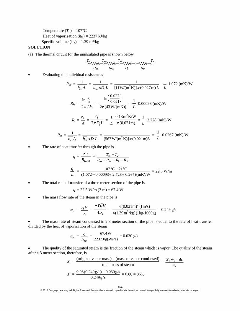
164 © 2018 Cengage Learning. All Rights Reserved. May not be scanned, copied or duplicated, or posted to a publicly accessible website, in whole or in part.
Temperature (Tst) = 107°C
Heat of vaporization (hfg) = 2237 kJ/kg
Specific volume ( s) = 1.39 m3/kg
SOLUTION
(a) The thermal circuit for the uninsulated pipe is shown below
Evaluating the individual resistances
Rco = 1
co oh A =
1
co oh D L =
2
1 1
[11W/(m K)] (0.027m) LL 1.072 (mK)/W
Rks = ln
2
o
i
r
r
iLk =
0.027ln
0.021
2 [43W/(mK)] =
1
L 0.00093 (mK)/W
Rf = fr
A =
2
f
i
r
D L =
1
L
20.18m K/W
(0.021m) =
1
L 2.728 (mK)/W
Rci = 1
ci ih A=
1
ci ih D L =
2
1
[567 W/(m K)] (0.021m)L =
1
L 0.0267 (mK)/W
The rate of heat transfer through the pipe is
q = total
T
R = st
ks i ci
T T
R R R R
q
L =
107°C 21°C
(1.072 0.00093 2.728 0.267)(mK)/W = 22.5 W/m
The total rate of transfer of a three meter section of the pipe is
q = 22.5 W/m (3 m) = 67.4 W
The mass flow rate of the steam in the pipe is
sm = i
s
A V =
2
4
i
s
D V =
2
3
(0.021m) (1m/s)
4(1.39m /kg)(1kg/1000g) = 0.249 g/s
The mass rate of steam condensed in a 3 meter section of the pipe is equal to the rate of heat transfer
divided by the heat of vaporization of the steam
cm =
fg
q
h =
67.4W
2237J/g(Ws/J) = 0.030 g/s
The quality of the saturated steam is the fraction of the steam which is vapor. The quality of the steam
after a 3 meter section, therefore, is
Xi = (original vapor mass) (mass of vapor condensed)
total mass of steam = i s c
s
X m m
m
Xi = 0.98(0.249g/s) 0.030g/s
0.249g/s = 0.86 = 86%

165 © 2018 Cengage Learning. All Rights Reserved. May not be scanned, copied or duplicated, or posted to a publicly accessible website, in whole or in part.
The quality of the steam changed by 12%.
The thermal circuit for the pipe with insulation is shown below
The convective resistance on the outside of the pipe is different than that in part (a) because it is based
on the outer area of the insulation
Rco = 1
co oh A =
1
( 2 )co o ih D L L =
2
1
[11W/(m K)] (0.027 m+0.1m)L =
1
L 0.228 (mK)/W
The thermal resistance of the insulation is
Rki =
2 0.027 0.1ln ln
0.027
2 2 [0.059W/(mK)]
o i
i
i
D L
r
Lk =
1
L 4.18 (mK)/W
The rate of heat transfer is
q = total
T
R =
si
ki ks f ci
T T
R R R R R
q
L =
107°C 21°C
(0.228 4.18 0.00093 2.728 0.0267)(mK)/W = 12.0 W/m
Therefore, the rate of steam condensed in 3 meters is
cm =
fg
q
h =
12.0*3W
2237J/g (Ws/J) = 0.016 g/s
The quality of the steam after 3 meters of pipe is
Xf = 0.98(0.249g/s) 0.016g/s
0.249g/s = 0.92 = 92%
The change in the quality of the steam is 6%.
COMMENTS
Notice that the resistance of the steel pipe and the convective resistance on the inside of the pipe are
negligible compared to the other resistances.
The resistance of the dirt film is the dominant resistance for the uninsulated pipe.

166 © 2018 Cengage Learning. All Rights Reserved. May not be scanned, copied or duplicated, or posted to a publicly accessible website, in whole or in part.
PROBLEM 2.18
Estimate the rate of heat loss per unit length from a 5 cm ID, 6 cm OD steel pipe covered with
high temperature insulation having a thermal conductivity of 0.11 W/(m K) and a thickness of 1.2
cm. Steam flows in the pipe. It has a quality of 99% and is at 150°C. The unit thermal resistance
at the inner wall is 0.0026 (m2 K)/W, the heat transfer coefficient at the outer surface is 17 W/(m2
K), and the ambient temperature is 16°C.
GIVEN
Insulated, steam filled steel pipe
Diameters
ID of pipe (Di) = 5 cm=0.05 m
OD of pipe (Do) = 6 cm=0.06 m
Thickness of insulation (Li) = 1.2 cm=0.012 m
Steam quality = 99%
Steam temperature (Ts) = 150°C
Unit thermal resistance at inner wall (A Ri) = 0.026 (m2 K)/W
Heat transfer coefficient at outer wall (ho) = 17 W /(m2 K)
Ambient temperature (T ) = 16°C
Thermal conductivity of the insulation (kI) = 0.11 W /(m K)
FIND
Rate of heat loss per unit length (q/L)
ASSUMPTIONS
1% carbon steel
Constant thermal conductivities
Steady state conditions
SKETCH
PROPERTIES AND CONSTANTS
From Appendix 2, Table 10
The thermal conductivity of 1% carbon steel (ks) = 43 W/(m2 °K) at 20 °C
SOLUTION
The outer diameter of the insulation (DI) = 6 cm + 2(1.2 cm) = 8.4 cm
The thermal circuit of the insulated pipe is shown below
The values of the individual resistances are
Ri = i i
i i
AR AR
A D L =
20.0026( K)/
0.05
m W
L m =
1
L 0.01655 (m K)/W

167 © 2018 Cengage Learning. All Rights Reserved. May not be scanned, copied or duplicated, or posted to a publicly accessible website, in whole or in part.
Rks =
ln
2
o
i
s
D
D
Lk =
0.06ln
0.05
2 * * 43 /(m )
m
m
L W K
=
1
L 0.000675 (m K)/W
RkI =
ln
2
I
o
i
D
D
Lk =
0.084ln
0.06
2 *0.11 /(m )
m
m
L W K
=
1
L 0.487 (m K)/W
Rco = 1
co oh A=
1
co Ih D L =
1
[17 / ( )] 0.084W mK m L =
1
L 0.223 (m K)/W
The rate of heat transfer is
q = total
T
R =
i
s
ks kI co
T T
R R R R
q
L =
150 16
(0.01655 0.000675 0.487 0.223)(h ft °F )/Btu
C C
= 184 W/m

168 © 2018 Cengage Learning. All Rights Reserved. May not be scanned, copied or duplicated, or posted to a publicly accessible website, in whole or in part.
PROBLEM 2.19
The rate of heat flow per unit length q/L through a hollow cylinder of inside radius ri and outside
radius ro is
q/L = ( A k T)/(ro – ri)
where A = 2 (ro – ri)/ln(ro/ri). Determine the per cent error in the rate of heat flow if the
arithmetic mean area (ro + ri) is used instead of the logarithmic mean area A for ratios of
outside to inside diameters (Do/Di) of 1.5, 2.0, and 3.0. Plot the results.
GIVEN
A hollow cylinder
Inside radius = ri
Outside radius = ro
Heat flow per unit length as given above
FIND
(a) Per cent error in the rate of heat flow if the arithmetic rather than the logarithmic mean area is used for
ratios of outside to inside diameters of 1.5, 2.0, and 3.0.
(b) Plot the results
ASSUMPTIONS
Radial conduction only
Constant thermal conductivity
Steady state prevails
SKETCH
SOLUTION
The rate of heat transfer per unit length using the logarithmic mean area is
log
q
L =
2 ( )
ln
o i
o
i
r r
r
r
o i
k T
r r =
2
ln o
i
k T
r
r
The rate of heat transfer per unit length using the arithmetic mean area is
arith
q
L = (ro + ri)
o i
k T
r r = k T o i
o i
r r
r r
The per cent error is

169 © 2018 Cengage Learning. All Rights Reserved. May not be scanned, copied or duplicated, or posted to a publicly accessible website, in whole or in part.
% error = log arith
log
q q
L L
q
L
100 =
2
ln
2
ln
o
i
o
i
o i
ro ir
r
r
r rk Tk T
r r
k T 100
% error =
11
1 ln2
1
o
o i
i o
i
r
r r
r r
r
100
For a ratio of outside to inside diameters of 1.5
% error = 1 1.5 1
1 ln (1.5)2 1.5 1
100 = – 1.37%
The percent errors for the other diameter ratios can be calculated in a similar manner with
the following results
Diameter ratio % Error
1.5 –1.37
2.0 –3.97
3.0 –9.86
(b)
COMMENTS
For diameter ratios less than 2, use of the arithmetic mean area will not introduce more than
a 4% error.

170 © 2018 Cengage Learning. All Rights Reserved. May not be scanned, copied or duplicated, or posted to a publicly accessible website, in whole or in part.
PROBLEM 2.20
A 2.5-cm-OD, 2-cm-ID copper pipe carries liquid oxygen to the storage site of a space shuttle at –
183°C and 0.04 m3/min. The ambient air is at 21°C and has a dew point of 10°C. How much
insulation with a thermal conductivity of 0.02 W/(m K) is needed to prevent condensation on the
exterior of the insulation if hc + hr = 17 W/(m2 K) on the outside?
GIVEN
Insulated copper pipe carrying liquid oxygen
Inside diameter (Di) = 2 cm = 0.02 m
Outside diameter (Do) = 2.5 cm = 0.025 m
LOX temperature (Tox) = – 183°C
LOX flow rate (mox) = 0.04 m3/min
Thermal conductivity of insulation (ki) = 0.02 W/(m K)
Exterior heat transfer coefficients (ho = hc + hr) = 17 W/(m2 K)
Ambient air temperature (T ) = 21°C
Ambient air dew point (Tdp) = 10°C
FIND
Thickness of insulation (L) needed to prevent condensation
ASSUMPTIONS
Steady-state conditions have been reached
The thermal conductivity of the insulation does not vary appreciably with temperature
Radial conduction only
The thermal resistance between the inner surface of the pipe and the liquid oxygen is negligible, therefore Twi =
Tox
SKETCH
PROPERTIES AND CONSTANTS
From Appendix 2, Table 12, thermal conductivity of copper (kc) = 401 W/(m K) at 0°C
SOLUTION
The thermal circuit for the pipe is shown below
The rate of heat transfer from the pipe is

171 © 2018 Cengage Learning. All Rights Reserved. May not be scanned, copied or duplicated, or posted to a publicly accessible website, in whole or in part.
q = total
T
R =
ln ln1
2 2
oI
o i
ox
DD
D D
I co I
T T
Lk Lkh A
The rate of heat transfer by convection and radiation from the outer surface of the pipe is
q o
T
R =
1I
o i
T T
h A
Equating these two expressions
ln ln1
2 2
oI
o i
ox
DD
D D
I co I
T T
Lk Lkh A
= 1
I
o I
T T
h A
ox
I
T T
T T =
ln ln1
2 2
1
oI
o i
DD
D D
I co I
o I
Lk Lkh D L
h D L
ox
I
T T
T T = 1 +
2
oI
hD
ln ln oI
o i
DD
D D
I ck k
DI
lnlnlno
i
D
DoI
I I c
DD
k k k
= 2
oh 1ox
I
T T
T T
DI
0.025ln
ln ln (0.025) 0.02
0.02W/(m K) 0.02W/(m K) 401W/(m K)
ID
= 2
2
17W/(m K)
o o
o o
21 C (183 C)
21 C 10 CID
ln184.4 0.00056
0.02
ID
= 2.064 (m2 K)/W
Solving this by trial and error
DI = 0.054 m = 5.4 cm
Therefore, the thickness of the insulation is
L = 2
I oD D =
5.4cm 2.5cm
2 = 1.5 cm
COMMENTS
Note that the thermal resistance of the copper pipe is negligible compared to that of the insulation.
172 © 2018 Cengage Learning. All Rights Reserved. May not be scanned, copied or duplicated, or posted to a publicly accessible website, in whole or in part.
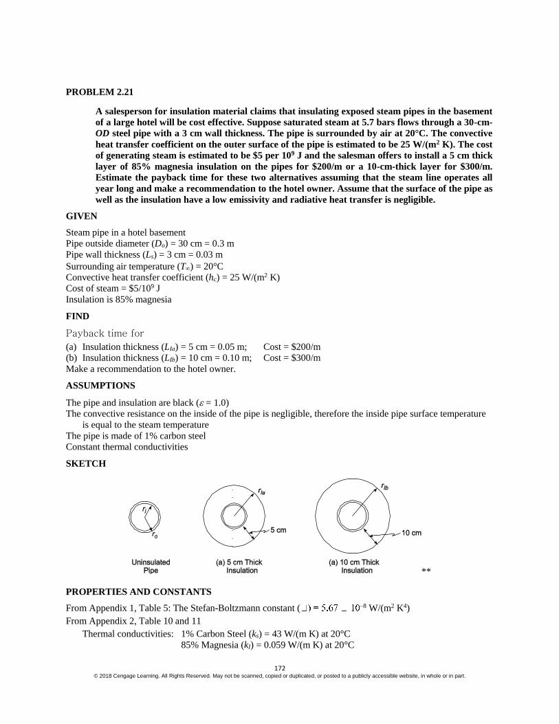
PROBLEM 2.21
A salesperson for insulation material claims that insulating exposed steam pipes in the basement
of a large hotel will be cost effective. Suppose saturated steam at 5.7 bars flows through a 30-cm-
OD steel pipe with a 3 cm wall thickness. The pipe is surrounded by air at 20°C. The convective
heat transfer coefficient on the outer surface of the pipe is estimated to be 25 W/(m2 K). The cost
of generating steam is estimated to be $5 per 109 J and the salesman offers to install a 5 cm thick
layer of 85% magnesia insulation on the pipes for $200/m or a 10-cm-thick layer for $300/m.
Estimate the payback time for these two alternatives assuming that the steam line operates all
year long and make a recommendation to the hotel owner. Assume that the surface of the pipe as
well as the insulation have a low emissivity and radiative heat transfer is negligible.
GIVEN
Steam pipe in a hotel basement
Pipe outside diameter (Do) = 30 cm = 0.3 m
Pipe wall thickness (Ls) = 3 cm = 0.03 m
Surrounding air temperature (T) = 20°C
Convective heat transfer coefficient (hc) = 25 W/(m2 K)
Cost of steam = $5/109 J
Insulation is 85% magnesia
FIND
Payback time for
(a) Insulation thickness (LIa) = 5 cm = 0.05 m; Cost = $200/m
(b) Insulation thickness (LIb) = 10 cm = 0.10 m; Cost = $300/m
Make a recommendation to the hotel owner.
ASSUMPTIONS
The pipe and insulation are black ( = 1.0)
The convective resistance on the inside of the pipe is negligible, therefore the inside pipe surface temperature
is equal to the steam temperature
The pipe is made of 1% carbon steel
Constant thermal conductivities
SKETCH
**
PROPERTIES AND CONSTANTS
From Appendix 1, Table 5: The Stefan-Boltzmann constant ( –8 W/(m2 K4)
From Appendix 2, Table 10 and 11
Thermal conductivities: 1% Carbon Steel (ks) = 43 W/(m K) at 20°C
85% Magnesia (kI) = 0.059 W/(m K) at 20°C

173 © 2018 Cengage Learning. All Rights Reserved. May not be scanned, copied or duplicated, or posted to a publicly accessible website, in whole or in part.
From Appendix 2, Table 13
The temperature of saturated steam at 5.7 bars (Ts) = 156°C
SOLUTION
The rate of heat loss and cost of the uninsulated pipe will be calculated first.
The thermal circuit for the uninsulated pipe is shown below
Evaluating the individual resistances
Rks =
ln
2
o
i
s
r
r
Lk =
0.15ln
10.12
2 [43W/(m K)] L 0.000826 (m K)/W
Rco = 1
c oh A =
1
2c oh r L =
2
1
[25W/(m K)]2 (0.15m)L =
1
L 0.0424 (m K)/W
The rate of heat transfer for the uninsulated pipe is
q = total
T
R =
ks co
sT T
R R
q
L =
o o156 C 20 C
(0.000826 0.0424)(K m) / W = 3148 W/m
The cost to supply this heat loss is
cost = (3148 w/m) (J/W s) (3600 s/h) (24 h/day) (365 days/yr) ($5/109J) = $496/(yr m)
For the insulated pipe the thermal circuit is
The resistance of the insulation is given by:
RkIa =
aln
2
I
o
I
r
r
Lk =
0.2ln
10.15
2 [0.059W/(mK)] L 0.776 (m K)/W
RkIb =
ln
2
Io
o
I
r
r
Lk =
0.25ln
10.15
2 [0.059W/(mK)] L 1.378 (m K)/W
(a) The rate of heat transfer for the pipe with 5 cm of insulation is
q = total
T
R = s
ks kIa co
T T
R R R
q
L =
o o156 C 20 C
(0.000826 0.776 0.0424)(Km)/W = 166 W/m

174 © 2018 Cengage Learning. All Rights Reserved. May not be scanned, copied or duplicated, or posted to a publicly accessible website, in whole or in part.
The cost of this heat loss is
cost = (166 w/m) (J/W s) (3600 s/h) (24 h/day) (365 days/yr) ($5/109J) = $26/yr m
Comparing this cost to that of the uninsulated pipe we can calculate the payback period
Payback period = Cost of installation $200 / m
uninsulated cost insulated cost $496 /(yr m) $26 /(yr m)
Payback period = 0.43 yr = 5 months
(b) The rate of heat loss for the pipe with 10 cm of insulation is
q = total
T
R = s
ks kIb co
T T
R R R
q
L =
o o156 C 20 C
(0.000826 1.378 0.0424)(Km)/W = 95.7 W/m
The cost of this heat loss
cost = (95.7 w/m) (J/W s) (3600 s/h) (24 h/day) (365 days/yr) ($5/109 J) = $15/yr m
Comparing this cost to that of the uninsulated pipe we can calculate the payback period
Payback period = $300 / m
$496 / yr m $15/ yr m = 0.62 yr = 7.5 months
COMMENTS
The 5 cm insulation is a better economic investment. The 10 cm insulation still has a short payback period and
is the superior environmental investment since it is a more energy efficient design. Moreover, energy costs are
likely to increase in the future and justify the investment in thicker insulation.

175 © 2018 Cengage Learning. All Rights Reserved. May not be scanned, copied or duplicated, or posted to a publicly accessible website, in whole or in part.
PROBLEM 2.22
A cylindrical liquid oxygen (LOX) tank has a diameter of 1.22 m, a length of 6.1 m, and
hemispherical ends. The boiling point of LOX is – 179.4°C. An insulation is sought which will
reduce the boil-off rate in the steady state to no more than 11.3 kg/h. The heat of vaporization of
LOX is 214 kJ/kg. If the thickness of this insulation is to be no more than 7.5 cm, what would the
value of its thermal conductivity have to be?
GIVEN
Insulated cylindrical tank with hemispherical ends filled with LOX
Diameter of tank (Dt) = 1.22 m
Length of tank (Lt) = 6.1 m
Boiling point of LOX (Tbp) = –179.40C
Heat of vaporization of LOX (hfg) = 214 kJ/kg
Steady state boil-off rate ( m ) = 11.2 kg/h
Maximum thickness of insulation (L) = 7.5 cm = 0.075 m
FIND
The thermal conductivity (k) of the insulation necessary to maintain the boil-off rate below 11.2 kg/h.
ASSUMPTIONS
The length given includes the hemispherical ends
The thermal resistance of the tank is negligible compared to the insulation
The thermal resistance at the interior surface of the tank is negligible
SKETCH
SOLUTION
The tank can be thought of as a sphere (the ends) separated by a cylindrical section, therefore the total heat
transfer is the sum of that through the spherical and cylindrical sections. The steady state conduction through a
spherical shell with constant thermal conductivity, from Equation (2.50), is
qs = 4 ( )o i o i
o i
K r r T T
r r
The rate of steady state conduction through a cylindrical shell, from Equation (2.37), is
qc = 2 Lc k
ln
o i
o
i
T T
r
r
(Lc = Lt – 1.22 m = 4.88 m)
The total heat transfer through the tank is the sum of these

176 © 2018 Cengage Learning. All Rights Reserved. May not be scanned, copied or duplicated, or posted to a publicly accessible website, in whole or in part.
q = qs + qc = 4 ( )o i o i
o i
k r r T T
r r + 2 Lc k
( )
ln
o i
o
i
T T
r
r
= 2 k (To – Ti) 2
ln
o i c
o i o
i
r r L
r r r
r
The rate of heat transfer required to evaporate the liquid oxygen at m is m hfg, therefore
sm hfg = 2 k (To – Ti)
2
ln
o i c
o i o
i
r r L
r r r
r
k =
2
2 ( )ln o
i
fg
o i co i r
o i r
mh
r r Lk T T
r r
k =
0.6850.61
11.3 /h*(1/3600 s) (254 /kg) * (1000 / )
2(0.685)(0.61) 4.882 [20 ( 179.4 )]
0.075 ln
kg kJ J kJ
C C
k = 0.0119 W/(m K)
COMMENTS
Based on data given in Appendix 2, Table 11, no common insulation has such low value of thermal
conductivity. However, Marks Standard Handbook for Mechanical Engineers lists the thermal conductivity of
expanded rubber board, ‘Rubatex’, at –180°C to be 0.007 W/(m K).

177 © 2018 Cengage Learning. All Rights Reserved. May not be scanned, copied or duplicated, or posted to a publicly accessible website, in whole or in part.
PROBLEM 2.23
The addition of insulation to a cylindrical surface, such as a wire, may increase the rate of heat
dissipation to the surroundings (see Problem 2.15). (a) For a No. 10 wire (0.26 cm in diameter),
what is the thickness of rubber insulation [k = 0.16 W/(m K)] that maximizes the rate of heat loss
if the heat transfer coefficient is 10 W/(m2 K)? (b) If the current-carrying capacity of this wire is
considered to be limited by the insulation temperature, what per cent increase in capacity is
realized by addition of the insulation? State your assumptions.
GIVEN
An insulated cylindrical wire
Diameter of wire (Dw) = 0.26 cm = 0.0026 m
Thermal conductivity of rubber (k) = 0.16 W/(m K)
Heat transfer coefficient ( ch ) = 10 W/(m2 K)
FIND
(a) Thickness of insulation (Li) to maximize heat loss
(b) Per cent increase in current carrying capacity
ASSUMPTIONS
The system is in steady state
The thermal conductivity of the rubber does not vary with temperature
SKETCH
SOLUTION
(a) From Problem 2.15, the radius that will maximize the rate of heat transfer (rc) is:
rc = k
h =
2
0.16W/(mK)
10W/(m K) = 0.016 m
The thickness of insulation needed to make this radius is
Li = rc – rw = 0.016 m – 0.0026m
2 = 0.015 m = 1.5 cm
(b) The thermal circuit for the insulated wire is shown below
where RkI =
ln
2
o
i
r
r
Lk and Rc =
1
ch A =
1
2c oh r L
The rate of heat transfer from the wire is

178 © 2018 Cengage Learning. All Rights Reserved. May not be scanned, copied or duplicated, or posted to a publicly accessible website, in whole or in part.
q = total
T
R = Ii
kI c
T T
R R =
2 ( )
ln 1o
i
Ii
r
r
c o
L T T
k h r
If only a very thin coat of insulation is put on the wire to insulate it electrically then ro = ri = Dw/2 = 0.0013 m.
The rate of heat transfer from the wire is
q
L =
2
2 ( )
10
10 W/(m K)(0.0013m)
IiT T = 0.082 (TIi – T)
For the wire with the critical insulation thickness
q
L =
0.0160.0013
2
2 ( )
ln 1
0.16W/(m K) 10W/(m K)(0.016m)
IiT T
= 0.286 (TIi – T)
The current carrying capacity of the wire is directly related to the rate of heat transfer from the wire. For a
given maximum allowable insulation temperature, the increase in current carrying capacity of the wire with the
critical thickness of insulation over that of the wire with a very thin coating of insulation is
% increase = thin coat
thin coat
ar
q q
L L
q
L
100 = 0.286 0.082
0.082 100 = 250%
COMMENTS
This would be an enormous amount of insulation to add to the wire changing a thin wire into a rubber cable
over an inch in diameter and would not be economically justifiable. Thinner coatings of rubber will achieve
smaller increases in current carrying capacity.

179 © 2018 Cengage Learning. All Rights Reserved. May not be scanned, copied or duplicated, or posted to a publicly accessible website, in whole or in part.
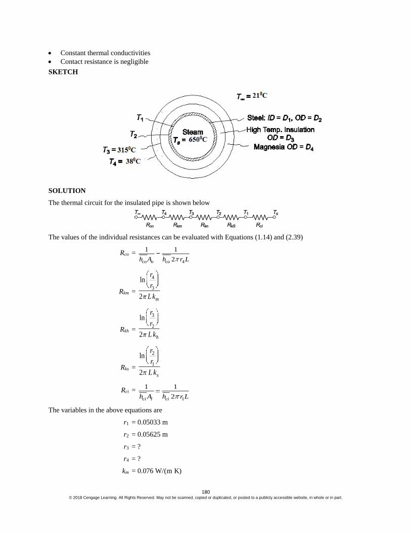
PROBLEM 2.24
A standard 4 10 cm steel pipe (ID = 10.066 cm., OD = 11.25 cm) carries superheated steam at
650°C in an enclosed space where a fire hazard exists, limiting the outer surface temperature to
38°C. To minimize the insulation cost, two materials are to be used; first a high temperature
(relatively expensive) insulation is to be applied to the pipe and then magnesia (a less expensive
material) on the outside. The maximum temperature of the magnesia is to be 315°C. The
following constants are known.
Steam-side coefficient h = 500 W/(m2 K)
High-temperature insulation conductivity k = 0.1 W/(m K)
Magnesia conductivity k = 0.076 W/(m K)
Outside heat transfer coefficient h = 11 W/(m2 K)
Steel conductivity k = 43 W/(m K)
Ambient temperature Ta = 21°C
(a) Specify the thickness for each insulating material.
(b) Calculate the overall heat transfer coefficient based on the pipe OD.
(c) What fraction of the total resistance is due to (1) steam-side resistance, (2) steel pipe
resistance, (3) insulation (combination of the two), and (4) outside resistance?
(d) How much heat is transferred per hour, per foot length of pipe?
GIVEN
Steam filled steel pipe with two layers of insulation
Pipe inside diameter (Di) = 10.066 cm=0.10066 m
Pipe outside diameter (Do) = 11.25 cm=0.1125 m
Superheated steam temperature (Ts) = 650°C
Maximum outer surface temperature (Tso) = 38°C
Maximum temperature of the Magnesia (Tm) = 315°C
Thermal conductivities
High-temperature insulation (kh) = 0.1 W/(m K)
Magnesia (km) = 0.076 W/(m K)
Steel (ks) = 43 W/(m K)
Heat transfer coefficients
Steam side (cih ) = 500 W/(m2 K)
Outside (coh ) = 11 W/(m2 K)
Ambient temperature (Ta) = 21°C
FIND
(a) Thickness for each insulation material
(b) Overall heat transfer coefficient based on the pipe OD
(c) Fraction of the total resistance due to
Steam-side resistance
Steel pipe resistance
Insulation
Outside resistance
(d) The rate of heat transfer per unit length of pipe (q/L)
ASSUMPTIONS
The system is in steady state
180 © 2018 Cengage Learning. All Rights Reserved. May not be scanned, copied or duplicated, or posted to a publicly accessible website, in whole or in part.
Constant thermal conductivities
Contact resistance is negligible
SKETCH
SOLUTION
The thermal circuit for the insulated pipe is shown below
The values of the individual resistances can be evaluated with Equations (1.14) and (2.39)
Rco =
4
1 1
2co o coh A h r L
Rkm =
4
3
ln
2 m
r
r
L k
Rkh =
3
2
ln
2 h
r
r
L k
Rks =
2
1
ln
2 s
r
r
L k
Rci =
1
1 1
2ci i cih A h r L
The variables in the above equations are
r1 = 0.05033 m
r2 = 0.05625 m
r3 = ?
r4 = ?
km = 0.076 W/(m K)

181 © 2018 Cengage Learning. All Rights Reserved. May not be scanned, copied or duplicated, or posted to a publicly accessible website, in whole or in part.
ks = 43 W/(m K)
kh = 0.1 W/(m K)
coh = 11 W/(m2 K)
cih = 500 W/(m2 K)
The temperatures for this problem are
Ts = 650 °C
T1 = ?
T2 = ?
T3 = 315 °C
T4 = 38 °C
Ta = 21 °C
There are five unknowns in this problem: q/L, T1, T2, r3, and r4. These can be solved for by writing the
equation for the heat transfer through each of the five resistances and solving them simultaneously.
1. Steam side convective heat transfer
q = ci
T
R = 2 cih r1 L (Ts – Tl) = 2 L 2[500 /(m K)] 0.05033W m (650 °C – T1)
q
L = 102775 – 158.12T1 W/m [1]
2. Conduction through the pipe wall
q = ks
T
R =
2
1
2
ln
sk L
r
r
(T1 – T2) = 2 [43 /(m )]
0.05625ln
0.05033
L W K
(T1 – T2)
q
L = 2429.5 (T1 – T2) W/m [2]
3. Conduction through the high temperature insulation
q = kh
T
R =
3
2
2
ln
hk L
r
r
(T2 – T3) =
2
3
2 [0.1 / )]
ln ln 0.05625
L W m K
r
(T2 – 315°C)
q
L =
3
0.628
ln 2.878r (T2 – 315) W/m [3]
4. Conduction through the magnesia insulation
q = km
T
R =
4
3
2
ln
mk L
r
r
(T3 – T4) =
2
4 3
2 [0.076 /( )]
ln ( ) ln( )
L W m K
r r
(315 °C – 38 °C)
q
L =
4 3
132.3
ln ( ) ln ( )r r W/m [4]
5. Air side convective heat transfer

182 © 2018 Cengage Learning. All Rights Reserved. May not be scanned, copied or duplicated, or posted to a publicly accessible website, in whole or in part.
q = co
T
R = 2 coh r4 L (T4 – Ta) = 2 L r4
2(11 / ( ))W m K (38 °C – 21 °C)
q
L = 1174.96 r4 W/m [5]
To maintain steady state, the heat transfer rate through each resistance must be equal. Equations [1] through [5]
are a set of five equations with five unknowns, they may be solved through numerical iterations using a simple
program or may be combined algebraically as follows
Substituting Equation [1] into Equation [2] yields
T2 = 1.065 T1 – 42.1
Substituting this into Equation [3] and combining the result with Equation [1]
ln r3 = 1
1
0.669 224.26
102775 158.12
T
T
– 2.878
Substituting this into Equation [4] and combining the result with Equation [1]
r4 = exp 1
1
0.669 13.62.878
102,775 158.12
T
T
Finally, substituting this into Equation [5] and combining the result with Equation [1]
126,480 – 105.4 T1 = 1174.96 exp 1
1
0.669 13.62.878
102,775 158.12
T
T
Solving this by trial and error: T1 = 648.15°C
This result can be substituted into the equations above to find the unknown radii
r3 = 0.1164 m = 11.64 cm r4 = 0.182 m = 18.2 cm
The thickness of the high temperature insulation = r3 – r2 = 6.015 cm
The thickness of the magnesia insulation = r4 – r3 = 6.56 cm
(b) Substituting T1 = 647°C into [1] yields a heat transfer rate of 289 W/m. The overall heat transfer
coefficient based on the pipe outside area must satisfy the following equation
q = U A2 (Ts – Ta) = U D2 L (Ts – Ta)
U = 2
1
( )s a
q
L D T T = 289 W/m
1
0.1125 (650 21 )C C
U = 1.30 W/(m2 K)
(c) The overall resistance for the insulated pipe is
Rtotal = 2
1
UA =
2
1
[1.30 /(m ) ] 0.1125W K L =
1
L 2.18 (K/W)
(1) The thermal resistance of the steam side convection is
Rci = 1
ci ih A =
1
1
2cih r L =
2
1 1
(500 /(m ))2 0.10066 LW K L 0.0095 K/W
The fraction of the resistance due to steam side convection = 0.0095/3.57 = 0.00.
(2) The thermal resistance of the steel pipe is

183 © 2018 Cengage Learning. All Rights Reserved. May not be scanned, copied or duplicated, or posted to a publicly accessible website, in whole or in part.
Rks =
2
1
ln
2 s
r
r
Lk =
0.05625ln
10.05033
2 [43 /(m )]L W K L
0.000412 K/W
The fraction of the resistance due to the steel pipe = 0.000412/2.18 = 0.00015
(3) The thermal resistance of the magnesia insulation is
Rkm =
4
3
ln
2 m
r
r
Lk =
0.182ln
10.1164
2 [0.076 /(mK)]L W L
0.936 K/W
The thermal resistance of the high temperature insulation is
Rkh =
3
2
ln
2 h
r
r
Lk =
0.1164ln
10.05625
2 [0.1 /( )]L W m K L
1.15 K/W
The fraction of the resistance due to the insulation = 2.09/2.18 = 0.96.
(4) The convective thermal resistance on the air side is
Rco =
4
1 1
2co o coh A h r L =
1
(11 /(m ))2 (0.182)W K L =
1
L 0.08 K/W
The fraction of the resistance due to air side convection = 0.08/2.18 = 0.04.
(d) The rate of heat transfer is
q = U A2 (Ts – Ta) = U D2 L (Ts – Ta)
q
L = 1.3 W/(m2 K) 2 0.05625 (650°C – 21°C) = 288 W/m
COMMENTS
Notice that the insulation accounts for 97% of the total thermal resistance and that the thermal resistance of the
steel pipe and the steam side convection are negligible.

184 © 2018 Cengage Learning. All Rights Reserved. May not be scanned, copied or duplicated, or posted to a publicly accessible website, in whole or in part.
PROBLEM 2.25
Show that the rate of heat conduction per unit length through a long hollow cylinder of inner
radius ri and outer radius ro, made of a material whose thermal conductivity varies linearly with
temperature, is given by
kq
L =
( ) /
i o
o i m
T T
r r k A
where Ti = temperature at the inner surface
To = temperature at the outer surface
A = 2 (ro – ri)/ln o
i
r
r
km = ko [1 + k (Ti + To)/2]
L = length of cylinder
GIVEN
A long hollow cylinder
The thermal conductivity varies linearly with temperature
Inner radius = ri
Outer radius = ro
FIND
Show that the rate of heat conduction per unit length is given by the above equation
ASSUMPTIONS
Conduction occurs in the radial direction only
Steady state prevails
SKETCH
SOLUTION
The rate of radial heat transfer through a cylindrical element of radius r is
q
L = k A
dT
dr = k 2 r
dT
dr = a constant
But the thermal conductivity varies linearly with the temperature
k = ko (1 + T)
q
L = 2 r ko (1 + T)
dT
dr
q
L
1
rdr = 2 ko (1 + T) dT
Integrating between the inner and outer radii

185 © 2018 Cengage Learning. All Rights Reserved. May not be scanned, copied or duplicated, or posted to a publicly accessible website, in whole or in part.
q
L
1o
i
r
r r dr = 2 ko (1 )o
i
T
TT dt
q
L (ln ro – ln ri) = 2 ko
2 2
2 2o o i iT T T T
q
L ln o
i
r
r = 2 ko
2 2( ) ( )2
o i o iT T T T
q
L =
2 ( )
ln ( )
o i
oo i
i
r r
rr r
r
ko (To – Ti) 1 ( )2
o iT T
q
L =
( )o i
A
r r km (To – Ti)
q
L =
o i
o i
m
T T
r r
k A
where A= 2 (ro – ri)/ln o
i
r
r
km = ko [1 + k (Ti + To)/2]

186 © 2018 Cengage Learning. All Rights Reserved. May not be scanned, copied or duplicated, or posted to a publicly accessible website, in whole or in part.
PROBLEM 2.26
A long, hollow cylinder is constructed from a material whose thermal conductivity is a function
of temperature according to k = 0.15 + 0.0018 T, where T is in C and k is in W/(m K). The inner
and outer radii of the cylinder are 12.5 and 25 cm, respectively. Under steady-state conditions,
the temperature at the interior surface of the cylinder is 427°C and the temperature at the
exterior surface is 93°C.
(a) Calculate the rate of heat transfer per meter length, taking into account the variation in
thermal conductivity with temperature. (b) If the heat transfer coefficient on the exterior
surface of the cylinder is 17 W/(m2 K), calculate the temperature of the air on the outside of
the cylinder.
GIVEN
A long hollow cylinder
Thermal conductivity (k) = 0.15+ 0.0018 T [T in °C, k in W/(m K)]
Inner radius (ri) = 12.5 cm
Outer radius (ro) = 25 cm
Interior surface temperature (Twi) = 427°C
Exterior surface temperature (Two) = 93°C
Exterior heat transfer coefficient (oh ) = 17 W/(m2 K)
Steady-state conditions
FIND
(a) The rate of heat transfer per meter length (q/L)
(b) The temperature of the air on the outside (T)
ASSUMPTIONS
Steady state heat transfer
Conduction occurs in the radial direction only
SKETCH
SOLUTION
(a) The rate of radial conduction is given by Equation (2.37)
q = – k A dT
dr
q = – (0.15+ 0.0018 T) 2 r L dT
dr

187 © 2018 Cengage Learning. All Rights Reserved. May not be scanned, copied or duplicated, or posted to a publicly accessible website, in whole or in part.
1
r dr = -
2 L
q (0.15+ 0.0018 T) dT
Integrating this from the inside radius to the outside radius
1o
i
r
r r dr = 2
(0.15 0.0018 )wo
wi
T
T
LT dt
q
In ro – ln ri = – 2 L
q [0.15 (Two – Twi) + 0.0009 (Two
2 – Twi2)]
ln o
i
r
r = 2
L
q [015 (Two – Twi) + 0.00009 (Two
2 – Twi2)]
q
L =
2
ln o
i
r
r
[0.15 (Two – Twi) + 0.0009 (Two2 – Twi
2)]
q
L =
2
25ln
12.5
[0.15 (427 – 93) + 0.0009 (4272 – 932)] W/m
q
L = 1871.1 W/m
(b) The conduction through the hollow cylinder must equal the convection from the outer surface in steady
state
q
L = oh Ao T = oh 2 ro (Two – T)
Solving for the air temperature
T = Two – q
L
1
2o oh r = 93 °C – 1871.1 W/m *
2
1
17 W/(m ) *2 0.25K m = 23°C

188 © 2018 Cengage Learning. All Rights Reserved. May not be scanned, copied or duplicated, or posted to a publicly accessible website, in whole or in part.
PROBLEM 2.27
Derive an expression for the temperature distribution in an infinitely long rod of uniform cross
section within which there is uniform heat generation at the rate of
1 W/m. Assume that the rod is attached to a surface at Ts and is exposed through a convective
heat transfer coefficient h to a fluid at Tf.
GIVEN
An infinitely long rod with internal heat generation
Temperature at one end = Ts
Heat generation rate ( Gq A) = 1 W/m
Convective heat transfer coefficient = hc
Ambient fluid temperature = Tf
FIND
Expression for the temperature distribution
ASSUMPTIONS
The rod is in steady state
The thermal conductivity (k) is constant
SKETCH
SOLUTION
Let A = the cross sectional area of the rod = D2/4
An element of the rod with heat flows is shown at the right
Conservation of energy requires that
Energy entering the element + Heat generation = Energy leaving the element
– k A dT
dxG
x x x
dTq A x k A
dx + ch D x [T(x) – Tf]
kA x x x
dT dT
dx dx = ch D x (T – Tf) – Gq A x
Dividing by x and letting x 0 yields
kA 2
2
d T
dx = ch D (T – Tf) – G
q A

189 © 2018 Cengage Learning. All Rights Reserved. May not be scanned, copied or duplicated, or posted to a publicly accessible website, in whole or in part.
2
2
d T
dx =
4 ch
D k (T – Tf) – Gq
k
Let = T – Tf and m2 = 4
( )
ch
D k
2
2
d
dx – m2 = Gq
k
This is a second order, linear, nonhomogeneous differential equation with constant coefficients. Its solution is
the addition of the homogeneous solution and a particular solution. The solution to the homogeneous equation
2
2
d
dx – m2 = 0
is determined by its characteristic equation. Substituting = ex and its derivatives into the homogeneous
equation yields the characteristic equation
2 ex – m2 ex = 0 = ± m
Therefore, the homogeneous solution has the form
h = C1 cmx + C2 e–mx
A particular solution for this problem is simply a constant
= ao
Substituting this into the differential equation
0 – m2 ao = Gq
k ao =
2
Gq
m k
Therefore, the general solution is
q = C1 emx + C2 e–mx +
2
Gq
m k
With the boundary conditions
= a finite number as x
= Ts – Tf at x = 0
From the first boundary condition, as x emx , therefore C1 = 0
From the second boundary condition
Ts – Tf = C2 + 2
Gq
m k C2 = Ts – Tf –
2
Gq
m k
The temperature distribution in the rod is
q = T(x) – Tf = 2
Gs f
qT T
m ke–mx +
2
Gq
m k
T(x) = Tf + 2
Gs f
qT T
m k e–mx +
2
Gq
m k

190 © 2018 Cengage Learning. All Rights Reserved. May not be scanned, copied or duplicated, or posted to a publicly accessible website, in whole or in part.
PROBLEM 2.28
Heat is generated uniformly in the fuel rod of a nuclear reactor. The rod has a long, hollow
cylindrical shape with its inner and outer surfaces at temperatures of Ti and To, respectively.
Derive an expression for the temperature distribution.
GIVEN
A long, hollow cylinder with uniform internal generation
Inner surface temperature = Ti
Outer surface temperature = To
FIND
The temperature distribution
ASSUMPTIONS
Conduction occurs only in the radial direction
Steady state prevails
SKETCH
SOLUTION
Let ri = the inner radius
ro = the outer radius
Gq = the rate of internal heat generation per unit volume
k = the thermal conductivity of the fuel rod
The one dimensional, steady state conduction equation in cylindrical coordinates is given in Equation (2.21)
1 d dT
rr dr dr
+ Gq
k = 0
d dT
rdr dr
= Grq
k
With boundary conditions
T = Ti at r = ri
T = To at r = ro
Integrating the conduction equation once
r dT
dr =
2
2
Gr q
k + C1
191 © 2018 Cengage Learning. All Rights Reserved. May not be scanned, copied or duplicated, or posted to a publicly accessible website, in whole or in part.
dT =
21
2
Gr q C
k rdr
Integrating again
T = 2
4
Gr q
k + C1 ln (r) + C2
Applying the first boundary condition
Ti = 2
4
i Gr q
k + C1 ln (ri) + C2
C2 = Ti + 2
4
i Gr q
k – Ci ln (ri)
Applying the second boundary condition
To = 2
4
o Gr q
k + C1 ln (ro) + C2
To = 2
4
o Gr q
k + C1 ln (ro) + Ti +
2
4
i Gr q
k – C1 ln (ri)
C1 =
2 2( )4
ln
Go i o i
o
i
qT T r r
k
r
r
Substituting the constants into the temperature distribution
T = 2
4
Gr q
k+
2 2( )4
ln
Go i o i
o
i
qT T r r
k
r
r
ln (r) + Ti +
2 22 ( )
4
4ln
Go i o i
i G
o
i
qT T r r
r q k
k r
r
T =
2 2
2 2
( ) ln
( )4
ln
o iG i
io
i
rr r
q rr r
k r
r
+
( ) ln
ln
o ii
o
i
rT T
r
r
r
+ Ti

192 © 2018 Cengage Learning. All Rights Reserved. May not be scanned, copied or duplicated, or posted to a publicly accessible website, in whole or in part.
PROBLEM 2.29
In a cylindrical fuel rod of a nuclear reactor, heat is generated internally according to the
equation
Gq = 1q 1
2
o
r
r
where gq = local rate of heat generation per unit volume at r
ro = outside radius
1q = rate of heat generation per unit volume at the centerline
Calculate the temperature drop from the center line to the surface for a 2.5 cm diameter rod
having a thermal conductivity of 26 W/(m K) if the rate of heat removal from its surface is 1.6
MW/ m2.
GIVEN
A cylindrical rod with internal generation and heat removal from its surface
Outside diameter (Do) = 2.5 cm=0.025 m
Rate of heat generation is as given above
Thermal conductivity (k) = 26 W/(m K)
Heat removal rate (q/A) = 1.6 MW/m2
FIND
The temperature drop from the center line to the surface (T)
ASSUMPTIONS
The heat flow has reached steady state
The thermal conductivity of the fuel rod is constant
One dimensional conduction in the radial direction
SKETCH
SOLUTION
The equation for one dimensional conduction in cylindrical coordinates is given in Equation (2.21)
1 d dT
rr dr dr
+ Gq
k = 0
d dT
rdr dr
= r
k1q
2
1o
r
r

193 © 2018 Cengage Learning. All Rights Reserved. May not be scanned, copied or duplicated, or posted to a publicly accessible website, in whole or in part.
With the boundary conditions
dT
dr = 0 at r = 0
T = Ts at r = ro
Integrating once
r dT
dr =
21
2
r q
k +
41
24 o
r q
k r + C1
From the first boundary condition: C1 = 0, therefore
dT
dr = 1
2
q
k
3
22 o
rr
r
Integrating again
T = 1
2
q
k
4 2
2 28 o
r r
r + C2
Evaluate this expression at the surface of the cylinder and at the centerline of the sphere and subtracting the
results gives us the temperature drop in the cylinder
T = T0 – or
T = 1
2
q
k
4 24 2
2 2
(0) (0)
2 28 8
o o
o o
r r
r r =
213
16
oq r
k
The rate of heat generation at the centerline (q1) can be evaluated using the conservation of energy. The total
rate of heat transfer from the cylinder must equal the total rate of heat generation within the cylinder
q
AA = L 1
0
or r
rq
4
21
o
r
r 2r dr
q
A 2 ro L = 2 L q1
2 4
2
02 4
or
o
r r
r
q
A ro = q1
2 2
2 4
o or r = q1
2
4
or
q1 = 4
or
q
A =
4
0.0125m [1.6*106 W/ m2] = 5.12 108 W/m2
Therefore, the temperature drop within the cylinder is
T =
28 23[5.12 10 / )] 0.0125
16[26 / ( )]
W m
W m K
= 577°C
194 © 2018 Cengage Learning. All Rights Reserved. May not be scanned, copied or duplicated, or posted to a publicly accessible website, in whole or in part.
PROBLEM 2.30
An electrical heater capable of generating 10,000 W is to be designed. The heating element is to
be a stainless steel wire, having an electrical resistivity of 80 10–6 ohm-centimeter. The
operating temperature of the stainless steel is to be no more than 1260°C. The heat transfer
coefficient at the outer surface is expected to be no less than 1720 W/(m2 K) in a medium whose
maximum temperature is 93°C. A transformer capable of delivering current at 9 and 12 V is
available. Determine a suitable size for the wire, the current required, and discuss what effect a
reduction in the heat transfer coefficient would have. (Hint: Demonstrate first that the
temperature drop between the center and the surface of the wire is independent of the wire
diameter, and determine its value.)
GIVEN
A stainless steel wire with electrical heat generation
Heat generation rate ( GQ ) = 10,000 W
Electrical resistivity () = 80 10–6 ohms-cm
Maximum temperature of stainless steel (Tmax) = 1260°C
Heat transfer coefficient ( ch ) = 1700 W/(m2 K)
Maximum temperature of medium (T) = 93°C
Voltage (V) = 9 or 12 V
FIND
(a) A suitable wire size: diameter (dw) and length (L)
(b) The current required (I)
(c) Discuss the effect of reduction in the heat transfer coefficient
ASSUMPTIONS
Variation in the thermal conductivity of stainless steel is negligible
The system is in steady-state
Conduction occurs in the radial direction only
SKETCH
PROPERTIES AND CONSTANTS
From Appendix 2, Table 10, Thermal conductivity of stainless steel (k) = 14.4 W/(m2 K)
SOLUTION
The rate of heat generation per unit volume is
Gq = volume
GQ =
2
G
w
Q
r L
The temperature distribution in a long cylinder with internal heat generation is given in
Section 2.3.3

195 © 2018 Cengage Learning. All Rights Reserved. May not be scanned, copied or duplicated, or posted to a publicly accessible website, in whole or in part.
T(r) = C2 – 2
4
Gq r
k
where C2 is a constant determined by boundary conditions. Therefore
T(0) – T(rw) – = [C2 – 0] – 2
24
G wq rC
k =
2
4
G wq r
k =
4
GQ
kL
The convective heat transfer from the outer surface must equal the internal heat generation
qc = ch A [T(rw) – T] = GQ
T(rw) – T = 2
G
w c
Q
r Lh
Adding the two temperature differences calculated above yields
[T(0) – T(rw)] + [T(rw) – T] = 4
GQ
kL+
2
G
w c
Q
r Lh
T(0) – T = 2
GQ 1 1
2w c
kL r Lh
The wire length and its radius are related through an expression for the electric power dissipation
GQ = Pe = 2
e
V
R =
2V
L
A
= 2 2
wV r
L L =
2 2w
G
V r
Q
T(0) – T = 2
2 22
GQ
V2 3
1 1
2 w w ck r r h
rw2 [T(0) – T] –
2
2 22
GQ
V
1
2
w
c
r
k h = 0
For the 12 volt case
rw3 (1260°C – 90°C) –
2 6
2 2
(10,000W) (80 10 ohm-cm)
2 (12 )(100cm/m)V 2
1
2 14.4 W/(mK) 1700 (W/(m K))
wr = 0
After checking the units, they are dropped for clarity
1167 rw3 – 0.0281(0.0347 r2 + 0.000581) = 0
Solving by trial and error
rw = 0.0025 m = 2.5 mm
For the 12 volt case, the suitable wire diameter is
dw = 2(rw) = 5 mm
The length of the wire required is
L = 2 2
6
(12V) (0.0025m) (100 cm/m)
80 10 ohm-cm(10,000W) = 0.353 m
The electrical resistance of this wire is
Re = 2
w
L
r =
6
2
80 10 ohm-cm(0.353m)
(0.0025m) *(100 cm/m)
= 0.0144 ohm
Therefore, the current required for the 12 volt case is

196 © 2018 Cengage Learning. All Rights Reserved. May not be scanned, copied or duplicated, or posted to a publicly accessible website, in whole or in part.
I = e
V
R =
12V
0.0144ohm = 833 amps
This same procedure can be used for the 9 volt case yielding
dw = 6.3 mm
L = 0.306 m
Re = 0.0081 ohm
I = 1111 amps
COMMENTS
The 5-mm-diameter wire would be a better choice since the amperage is less. However, 833 amps is still
extremely high.
The effect of a lower heat transfer coefficient would be an increase in the diameter and length of the wire as
well as an increase in the surface temperature of the wire.

197 © 2018 Cengage Learning. All Rights Reserved. May not be scanned, copied or duplicated, or posted to a publicly accessible website, in whole or in part.
STEADY STATE CONDUCTION IN SPHERE
PROBLEM 2.31
A hollow sphere with inner and outer radii of R1 and R2, respectively, is covered with a layer of
insulation having an outer radius of R3. Derive an expression for the rate of heat transfer
through the insulated sphere in terms of the radii, the thermal conductivities, the heat transfer
coefficients, and the temperatures of the interior and the surrounding medium of the sphere.
GIVEN
An insulated hollow sphere
Radii
Inner surface of the sphere = R1
Outer surface of the sphere = R2
Outer surface of the insulation = R3
FIND
Expression for the rate of heat transfer
ASSUMPTIONS
Steady state heat transfer
Conduction in the radial direction only
Constant thermal conductivities
SKETCH
SOLUTION
Let k12 = the thermal conductivity of the sphere
k23 = the thermal conductivity of the insulation
h1 = the interior heat transfer coefficient
h3 = the exterior heat transfer coefficient
Ti = the temperature of the interior medium
To = the temperature of the exterior medium
The thermal circuit for the sphere is shown below
The individual resistances are
Rc1 = 1 1
1
h A =
21 1
1
4h R L
From Equation (2.51)

198 © 2018 Cengage Learning. All Rights Reserved. May not be scanned, copied or duplicated, or posted to a publicly accessible website, in whole or in part.
Rk12 = 2 1
12 2 14
R R
k R R
Rk23 = 3 2
23 3 24
R R
k R R
Rc3 = 3 3
1
h A =
23 3
1
4h R L
The rate of heat transfer is
q = total
T
R =
1 12 23 3c k k c
T
R R R R
q =
3 22 1
2 212 2 1 23 3 21 1 3 3
1 1 1
4
T
R RR R
k R R k R RR h R h
q = 3 22 1
2 212 2 1 23 3 21 1 3 3
4
1 1
T
R RR R
k R R k R RR h R h
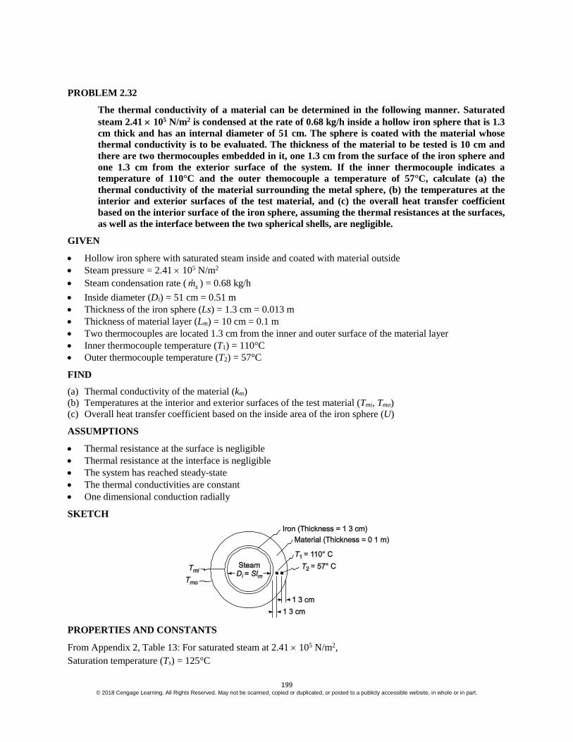
199 © 2018 Cengage Learning. All Rights Reserved. May not be scanned, copied or duplicated, or posted to a publicly accessible website, in whole or in part.
PROBLEM 2.32
The thermal conductivity of a material can be determined in the following manner. Saturated
steam 2.41 105 N/m2 is condensed at the rate of 0.68 kg/h inside a hollow iron sphere that is 1.3
cm thick and has an internal diameter of 51 cm. The sphere is coated with the material whose
thermal conductivity is to be evaluated. The thickness of the material to be tested is 10 cm and
there are two thermocouples embedded in it, one 1.3 cm from the surface of the iron sphere and
one 1.3 cm from the exterior surface of the system. If the inner thermocouple indicates a
temperature of 110°C and the outer themocouple a temperature of 57°C, calculate (a) the
thermal conductivity of the material surrounding the metal sphere, (b) the temperatures at the
interior and exterior surfaces of the test material, and (c) the overall heat transfer coefficient
based on the interior surface of the iron sphere, assuming the thermal resistances at the surfaces,
as well as the interface between the two spherical shells, are negligible.
GIVEN
Hollow iron sphere with saturated steam inside and coated with material outside
Steam pressure = 2.41 105 N/m2
Steam condensation rate ( sm ) = 0.68 kg/h
Inside diameter (Di) = 51 cm = 0.51 m
Thickness of the iron sphere (Ls) = 1.3 cm = 0.013 m
Thickness of material layer (Lm) = 10 cm = 0.1 m
Two thermocouples are located 1.3 cm from the inner and outer surface of the material layer
Inner thermocouple temperature (T1) = 110°C
Outer thermocouple temperature (T2) = 57°C
FIND
(a) Thermal conductivity of the material (km)
(b) Temperatures at the interior and exterior surfaces of the test material (Tmi, Tmo)
(c) Overall heat transfer coefficient based on the inside area of the iron sphere (U)
ASSUMPTIONS
Thermal resistance at the surface is negligible
Thermal resistance at the interface is negligible
The system has reached steady-state
The thermal conductivities are constant
One dimensional conduction radially
SKETCH
PROPERTIES AND CONSTANTS
From Appendix 2, Table 13: For saturated steam at 2.41 105 N/m2,
Saturation temperature (Ts) = 125°C

200 © 2018 Cengage Learning. All Rights Reserved. May not be scanned, copied or duplicated, or posted to a publicly accessible website, in whole or in part.
Heat of vaporization (hfg) = 2187 kJ/kg
SOLUTION
(a) The rate of heat transfer through the sphere must equal the energy released by the condensing steam:
q = sm hfg = 0.68 kg/hh
2187 kJ/kg 1000 J/kJ (Ws)/J3600s
= 413.1 W
The thermal conductivity of the material can be calculated by examining the heat transfer between the
thermocouple radii
q = 12k
T
R = 2 1
2 1
2 14 m
T T
r r
k r r
Solving for the thermal conductivity
km = 2 1
2 1 2 1
( )
4 ( )
q r r
r r T T
r1 = 2
iD + Ls + 0.013 m =
0.51m
2 + 0.013 m + 0.013 m = 0.281 m
r2 = 2
iD + Ls + Lm – 0.013 m =
0.51m
2 + 0.013 m + 0.1 m – 0.013 m = 0.355
km = 413.1W(0.355 m 0.281 m)
4 (0.355m)(0.281m)(110 57 )o oC C = 0.46 W/(m K)
(b) The temperature at the inside of the material can be calculated from the equation for conduction through
the material from the inner radius, the radius of the inside thermocouple
q = 1ki
T
R =
1
14
mi i
i
m i
T T
r r
k r r
Solving for the temperature of the inside of the material
Tmi = T1 + 1
1
( )
4
i
m i
q r r
k r r
ri = 2
iD + Lm =
0.51 m
2 + 0.013 m = 0.268 m
Tmi = 110°C + 413.1W(0.013m)
4 [0.46W/(mK)](0.281 m)(0.268m) = 122°C
The temperature at the outside radius of the material can be calculated from the equation for conduction
through the material from the radius of the outer thermocouple to the outer radius
q = 2k o
T
R = 2
2
24
mo
o
m o
T T
r r
k r r
Solving for the temperature of the outer surface of the material

201 © 2018 Cengage Learning. All Rights Reserved. May not be scanned, copied or duplicated, or posted to a publicly accessible website, in whole or in part.
Tmo = T2 – 2
2
( )
4
o
m o
q r r
k r r
ro = 2
iD + Ls + Lm =
0.51 m
2 + 0.013 m + 0.01 m = 0.368 m
Tmo = 57°C – 413.1W(0.013m)
4 [0.46W/(mK)](0.368 m)(0.355m) = 50°C
(c) The heat transfer through the sphere can be expressed as
q = U Ai T = U D12 (Ts – Tmo)
U = 2( )i s mo
q
D T T =
2
413.1 W
(0.51m) (125 C 50 C ) = 6.74 W/(m2 K)

202 © 2018 Cengage Learning. All Rights Reserved. May not be scanned, copied or duplicated, or posted to a publicly accessible website, in whole or in part.
PROBLEM 2.33
For the system outlined in Problem 2.31, determine an expression for the critical radius of the
insulation in terms of the thermal conductivity of the insulation and the surface coefficient
between the exterior surface of the insulation and the surrounding fluid. Assume that the
temperature difference, R1, R2, the heat transfer coefficient on the interior, and the thermal
conductivity of the material of the sphere between R1 and R2 are constant.
GIVEN
An insulated hollow sphere
Radii
Inner surface of the sphere = R1
Outer surface of the sphere = R2
Outer surface of the insulation = R3
FIND
An expression for the critical radius of the insulation
ASSUMPTIONS
Constant temperature difference, radii, heat transfer coefficients, and thermal conductivities
Steady state prevails
SKETCH
SOLUTION
Let k12 = the thermal conductivity of the sphere
k23 = the thermal conductivity of the insulation
h1 = the interior heat transfer coefficient
h3 = the exterior heat transfer coefficient
Ti = the temperature of the interior medium
To = the temperature of the exterior medium
From Problem 2.11, the rate of heat transfer through the sphere is
q = 3 22 1
2 212 2 1 23 3 21 1 3 3
4
1 1
T
R RR R
k R R k R RR h R h
The rate of heat transfer is a maximum when the denominator of the above equation is a minimum. This occurs
when the derivative of the denominator with respect to R3 is zero
3
d
dR 3 22 1
2 212 2 1 23 3 21 1 3 3
1 1R RR R
k R R k R RR h R h = 0 => –
3 3
2
h R +
23
1
k= 0
R3 = 23 32k h
The maximum heat transfer will occur when the outer insulation radius is equal to 2 k23/h3.

203 © 2018 Cengage Learning. All Rights Reserved. May not be scanned, copied or duplicated, or posted to a publicly accessible website, in whole or in part.
PROBLEM 2.34
Show that the temperature distribution in a sphere of radius ro, made of a homogeneous material
in which energy is released at a uniform rate per unit volume Gq , is
T(r) = To +
2G oq r
6 k1
2
o
r
r
GIVEN
A homogeneous sphere with energy generation
Radius = ro
FIND
Show that the temperature distribution is as shown above.
ASSUMPTIONS
Steady state conditions persist
The thermal conductivity of the sphere material is constant
Conduction occurs in the radial direction only
SKETCH
SOLUTION
Let k = the thermal conductivity of the material
To= the surface temperature of the sphere
Equation (2.23) can be simplified to the following equation by the assumptions of steady state and radial
conduction only
2
2
1 Gqd dTr
dr dr kr = 0
2d dTr
dr dr =
2Gr q
k
With the following boundary conditions
dT
dr = 0 at r = 0
T = To at r = ro

204 © 2018 Cengage Learning. All Rights Reserved. May not be scanned, copied or duplicated, or posted to a publicly accessible website, in whole or in part.
Integrating the differential equation once
r2 dT
dr =
3
3
Gr q
k + C1
From the first boundary condition
C1 = 0
Integrating once again
T = 2
6
Gr q
k + C2
Applying the second boundary condition
To = 2
6
o Gr q
k + C2 C2 = To +
2
6
o Gr q
k
Therefore, the temperature distribution in the sphere is
T = 2
6
Gr q
k + To +
2
6
o Gr q
k
T(r) = To + 2
6
G oq r
k
2
1o
r
r

205 © 2018 Cengage Learning. All Rights Reserved. May not be scanned, copied or duplicated, or posted to a publicly accessible website, in whole or in part.
PROBLEM 2.35
Liquid oxygen is to be stored on a service module of NASA’s new Orion Spacecraft (NASA, “Orion
Quick Facts,” FS-2014-08-004-JSC, Lyndon B. Johnson Space Center, Houston, TX) in a spherical
stainless steel container. The service module is depicted in the figure below (note the various spherical
containers shown), and the entire Orion Spacecraft is shown later in figure. 3.1(Chapter 3). The
container has an outside diameter of 1.0 m and a wall thickness of 10 mm. The boiling point of liquid
oxygen is 90 K, and its latent heat is 213 kJ/Kg. The tank is to be installed in an environment where loss
of oxygen from the container is not to exceed 1.0 kg/day. Tank is to be installed in service module where
ambient temperature is 225 K and convection coefficient is 5 W/ (m2 K). To ensure this calculate the
thermal conductivity of material used for insulation if its thickness is 10 cm.
GIVEN
Liquid oxygen container with 1.0 m diameter and 10 mm thickness.
Boiling point of oxygen (Tb)= 90 K
Ambient temperatue (T∞)=225 K
Convection coefficient (h)= 5 W/ (m2 K)
Latent heat of vaporization (hfg)= 213 kJ/kg
Loss of oxygen (ṁ)= 1.0 kg/day=1/86400 kg/sec
FIND
Suitable layer of insulation and its thickness.
ASSUMPTIONS
Steady state conditions persist
The insulation is uniform.
Properties remain constant.
SKETCH
PROPERTIES AND CONSTANTS
From Appendix 2, Table 10, Thermal conductivity of stainless steel (ks) = 14.4 W/(m2 K).
The material with lowest conductivity available is selected pertaining to light weight requirement for
spacecraft. From Appendix 2, Table 11, glass fiber is selected with conductivity of (kg)=0.035 W/ (m K).

206 © 2018 Cengage Learning. All Rights Reserved. May not be scanned, copied or duplicated, or posted to a publicly accessible website, in whole or in part.
SOLUTION
The inner and outer radius of the stainless steel sphere is
r1=0.5-0.01= 0.49 m
r2=0.5 m
r3=0.5+0.1=0.6 m
The rate of heat loss by vaporization is given by
q =1/86400*213*1000 J/sec = 2.465 W
This amount should be equal to heat loss by conduction through the sphere. Thus
q =
2
2 1 3 2
1 * 2 2 * 3 3
1
2* * * 2* * * 4* * *
b
s g
T TW
r r r r
k r r k r r h r
0.02652.465* 0.000225 0.04421 135
k
0.026554.767 0.044
k
2* *
225 902.465
0.50 0.49 0.6 0.5 1
4* *14.4*0.50 0.49 4* * *0.5 0.6 4* *5*0.6s
W
k
2* *
225 902.465
0.50 0.49 0.6 0.5 1
4* *14.4*0.50 0.49 4* * *0.5 0.6 4* *5*0.6s
W
k

207 © 2018 Cengage Learning. All Rights Reserved. May not be scanned, copied or duplicated, or posted to a publicly accessible website, in whole or in part.
k=0.0265/54.723 W/(m K)
=0.000484 W/(m K)
COMMENTS
Currently no material is available whose conductivity is as low as 0.000484 W/(m K). Scientists are working
on developing low conductivity material so that the thickness of insulation material required reduces which is
critical for developing light weight spacecraft.
208 © 2018 Cengage Learning. All Rights Reserved. May not be scanned, copied or duplicated, or posted to a publicly accessible website, in whole or in part.
PROBLEM 2.36
The development of contact lenses has transformed the solutions that are available today for
vision impairments. However, wearing them also poses several problems that includes the
condition of dry eyes due to lack of cooling, oxygenation, and moisturizing or lubrication of
cornea, among others. In a development phase of a new protective liquid for contact lenses, the
optometrist would like to know rate of heat loss from the anterior chamber of the eye through
the cornea and the contact lens. The system is modelled as a partial hollow sphere, as shown in
schematic diagram. The inner and outer radius of the cornea are respectively r1=10 mm and
r2=12.5 mm, and the outer radius of the fitted contact lens is r3=14.5 mm. The anterior chamber,
which contains the aqueous humor that provides nutrients to the cornea (as the later tissue has
no blood vessels), exposes the inner surface of the cornea to a temperature of Ti=36.90C with a
convective heat transfer coefficient of h̄i=10 W/(m2 K). The thermal conductivity of transparent
tissue of cornea is 0.35 W/(m K), and that of the contact lens material is 0.8 W/(m K). The outer
surface of the contact lens is exposed to room air at T0=220C and has a convection coefficient of
h̄0=5 W/(m2 K). Draw a thermal circuit for the system showing all of the temperature potentials
and thermal resistances. Then estimate the rate of heat loss from the anterior eye assuming that
steady state exists and eye aperture spherical angle is of 1000.
GIVEN
Inner radius of cornea r1=10 mm=0.01 m
Outer radius of cornea r2=12.5 mm=0.0125 m
Radius of contact lens r3=14.5 mm=0.0145 m
Inner cornea temperature Ti=36.90C
Inner convective heat transfer coefficient h̄i=10 W/(m2 K)
Conductivity of cornea tissue (k1)=0.35 W/(m K)
Conductivity of lens material (k2)=0.8 W/(m K)
Room air temperature T0=220C
Outer convection coefficient of h̄0=5 W/(m2 K)
FIND
Draw thermal circuit showing all temperature potentials and thermal resistances
Estimate rate of heat loss from anterior eye.
ASSUMPTIONS
Steady state conditions persist
Properties remain constant.
Eye is treated as partial hollow sphere sweeping an angle of θ =1000
SKETCH

209 © 2018 Cengage Learning. All Rights Reserved. May not be scanned, copied or duplicated, or posted to a publicly accessible website, in whole or in part.

210 © 2018 Cengage Learning. All Rights Reserved. May not be scanned, copied or duplicated, or posted to a publicly accessible website, in whole or in part.
PROPERTIES AND CONSTANTS
From Appendix 2, Table 10, Thermal conductivity of stainless steel (k)= 14.2 W/(m2 K)
SOLUTION
Since solid angle for complete sphere is 7200 or 4π the surface area reduces by the factor of 720
and thus
resistances increase by the factor of 720
.
The thermal circuit diagram for the problem is given as follows
Total heat loss with the lens is given by
q =0i
total
T T
R
Rtotal=R1+ R2+ R3+ R4
R1=2
* 1
720 1
4 ih r =7.2*
2
1
4 *10*0.01= 573 K/W
R2=2 1
1 * 1 2
720
4
r r
k r r
=
0.0125 0.017.2*
4 *0.35*0.0125*0.01
=32.74 K/W
R3=3 2
2 * 2 3
720
4
r r
k r r
=
0.0145 0.01257.2*
4 *0.8*0.0145*0.0125
=7.9 K/W
R4=2
* 3
720 1
4 oh r =7.2*
2
1
4 *5*0.0145= 545 K/W
Rtotal=R1+ R2+ R3+ R4= 1158.64 K/W
Total heat loss with the lens is
q =0i
total
T T
R
=
36.9 22
1158.64W
= 0.0129 W

211 © 2018 Cengage Learning. All Rights Reserved. May not be scanned, copied or duplicated, or posted to a publicly accessible website, in whole or in part.
PROBLEM 2.37
In cryogenic surgery, a small spherical probe is brought into contact with the diseased tissue
which is frozen and thereby destroyed. One such probe can be modeled as a 3-mm diameter
sphere whose surface is maintained at 240 K when the surrounding tissue is at 314 K. During
the surgical procedure, a thin layer of tissue freezes around the probe at a temperature of 273 K.
Assuming that the thermal conductivity of a frozen tissue is 1.5 W/(m K) and the heat transfer
mechanism at the surface is described by the effective convective coefficient of 50 W/(m2 K),
estimate the thickness of frozen tissue formed during a 30 min long operation.
GIVEN
Diameter of sphere(D1)= 3 mm, r1=0.0015 m
Probe surface temperature(Tp)= 240 K
Surrounding tissue temperature(Tt)= 314 K
Tissue freezing temperature(Tf)= 273 K
Thermal conductivity of frozen tissue(kt)= 1.5 W/(m K)
Effective convective coefficient (h̅)=50 W/(m2 K)
Operation time (t)= 30 min
FIND
Thickness of a frozen tissue formed
ASSUMPTIONS
1 dimensional Steady state conditions persist
Negligible contact resistance between probe and frozen tissue.
Constant properties.
SKETCH
SOLUTION
The thermal circuit diagram for the given as follows

212 © 2018 Cengage Learning. All Rights Reserved. May not be scanned, copied or duplicated, or posted to a publicly accessible website, in whole or in part.
The thickness of tissue in 30 mins is obtained by energy balance that is when rate of heat loss through
conduction is equal to rate of heat loss through convection, which means
q conduction= q convection
If r2 is the radius of frozen tissue at 30 mins
The convection heat loss
q convection= 2
2 t f*4 r T Th =50*4π* 2
2r *(314-273) =257612
2r
Conduction heat loss is given by
q conduction =2 1
1 24
f p
t
T T
r r
k r r
=
2
2
273 240
0.0015
4 *1.5*0.0015*
r
r
=
2
2
0.933
0.0015
r
r
Equating above two equations we get
257612
2r =2
2
0.933
0.0015
r
r
25761*r2=2
0.933
0.0015r
Solving the above equation, we get r2=0.007 m or 7 mm.
Thus the thickness of frozen tissue=r2-r1= 5.5 mm

213 © 2018 Cengage Learning. All Rights Reserved. May not be scanned, copied or duplicated, or posted to a publicly accessible website, in whole or in part.
EXTENDED SURFACES OR FINS
PROBLEM 2.38
The addition of aluminum fins has been suggested to increase the rate of heat dissipation from
one side of an electronic device 1-m-wide and 1-m-tall. The fins are to be rectangular in cross
section, 2.5-cm-long and 0.25-cm-thick. There are to be 100 fins per meter. The convective heat
transfer coefficient, both for the wall and the fins, is estimated at 35 W/(m2 K). With this
information, determine the per cent increase in the rate of heat transfer of the finned wall
compared to the bare wall.
GIVEN
Aluminum fins with a rectangular cross section
Dimensions: 2.5-cm-long and 0.25-mm-thick
Number of fins per meter = 100
The convective heat transfer coefficient ( ch ) = 35 W/(m2 K)
FIND
The per cent increase in the rate of heat transfer of the finned wall compared to the bare wall
ASSUMPTIONS
Steady state heat transfer
SKETCH
PROPERTIES AND CONSTANTS
From Appendix 2, Table 12
The thermal conductivity of aluminum (k) = 240 W/(m K) at 127°C
SOLUTION
Since the fins are of uniform cross section, Table 2.1 can be used to calculate the heat transfer rate from a
single fin with convection at the tip
qf = M
sinh ( ) cosh ( )( )
cosh ( ) sinh ( )
c
c
hmL mL
mk
hmL mL
mk
where M = ch P kA s = 2( ) ( )ch t w k tw s
s = Ts – T

214 © 2018 Cengage Learning. All Rights Reserved. May not be scanned, copied or duplicated, or posted to a publicly accessible website, in whole or in part.
For a 1 m width (w = 1 m)
M = 2 235W/(m K) 2(1.0025m) 240W/(m K) (0.025 m ) s = 6.49 s W/K
m L = ch P
kA = L
2( )
( )
ch t w
k tw = 0.025 m
2
2
35 W/(m K) 2(1.0025m)
240W/(m K) (0.0025 m )
L m = 0.025 m 1
10.81m
= 0.270
m K
ch =
235W/(m K)
110.81 240 W/(m K)
m
= 0.0135
Therefore, the rate of heat transfer from one fin, 1-meter-wide is:
qf = 6.49 s W/Ksin h (0.27) 0.0135 cos h (0.27)
cos h (0.27) 0.0135sin h (0.27)
qf = 1.792 s W/K
In 1 m2 of wall area there are 100 fins covering 100 tw = 100 (0.0025 m) (1 m) = 0.25 m2 of wall area leaving
0.75 m2 of bare wall. The total rate of heat transfer from the wall with fins is the sum of the heat transfer from
the bare wall and the heat transfer from 100 fins.
qtot = qbare + 100 qfin = h Abare s + 100 qfin
qtot = 235 W/(m K) (0.75 m2) s + 100 (1.792) s W/K = 205.3 s W/K
The rate of heat transfer from the wall without fins is
qbare = ch A s = 235 W/(m K) (1 m2) s = 35.0 W/K
The percent increase due to the addition of fins is
% increase = 205.3 35
35 100 = 486%
COMMENTS
This problem illustrates the dramatic increase in the rate of heat transfer that can be achieved with properly
designed fins.
The assumption that the convective heat transfer coefficient is the same for the fins and the wall is an
oversimplification of the real situation, but does not affect the final results appreciably. In later chapters, we
will learn how to evaluate the heat transfer coefficient from physical parameters and the geometry of the
system.
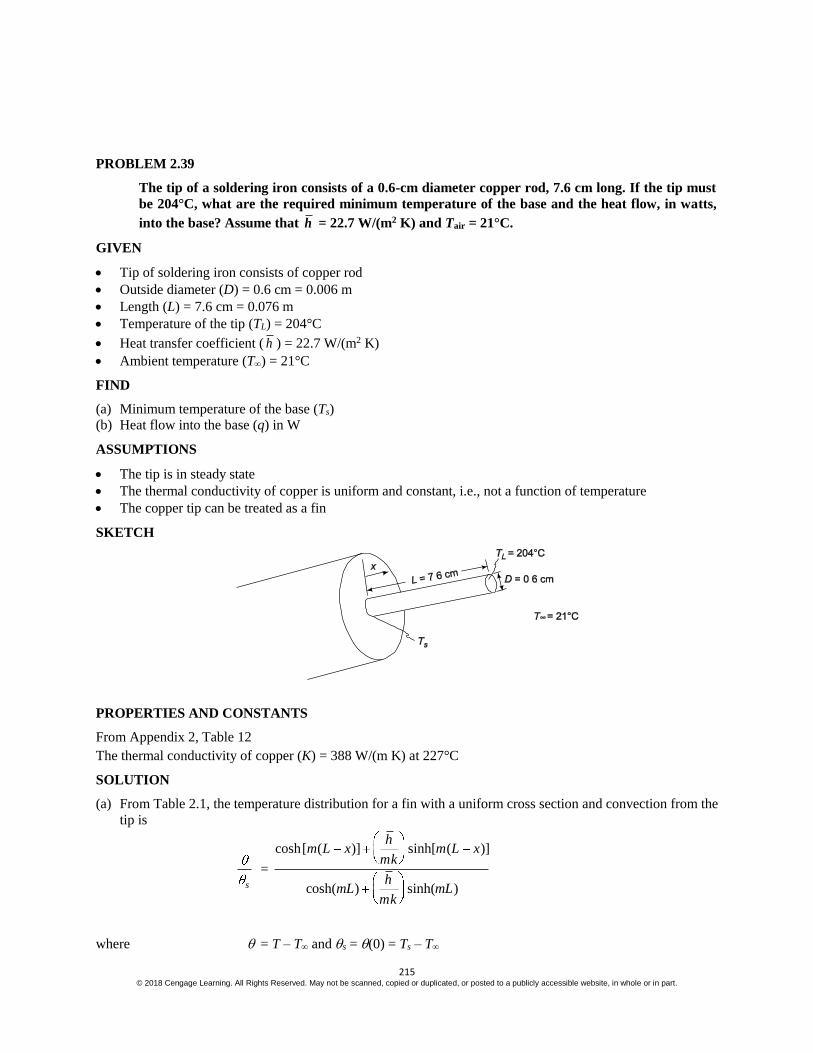
215 © 2018 Cengage Learning. All Rights Reserved. May not be scanned, copied or duplicated, or posted to a publicly accessible website, in whole or in part.
PROBLEM 2.39
The tip of a soldering iron consists of a 0.6-cm diameter copper rod, 7.6 cm long. If the tip must
be 204°C, what are the required minimum temperature of the base and the heat flow, in watts,
into the base? Assume that h = 22.7 W/(m2 K) and Tair = 21°C.
GIVEN
Tip of soldering iron consists of copper rod
Outside diameter (D) = 0.6 cm = 0.006 m
Length (L) = 7.6 cm = 0.076 m
Temperature of the tip (TL) = 204°C
Heat transfer coefficient ( h ) = 22.7 W/(m2 K)
Ambient temperature (T) = 21°C
FIND
(a) Minimum temperature of the base (Ts)
(b) Heat flow into the base (q) in W
ASSUMPTIONS
The tip is in steady state
The thermal conductivity of copper is uniform and constant, i.e., not a function of temperature
The copper tip can be treated as a fin
SKETCH
PROPERTIES AND CONSTANTS
From Appendix 2, Table 12
The thermal conductivity of copper (K) = 388 W/(m K) at 227°C
SOLUTION
(a) From Table 2.1, the temperature distribution for a fin with a uniform cross section and convection from the
tip is
s
=
cosh[ ( )] sinh[ ( )]
cosh( ) sinh( )
hm L x m L x
mk
hmL mL
mk
where = T – T and s = (0) = Ts – T

216 © 2018 Cengage Learning. All Rights Reserved. May not be scanned, copied or duplicated, or posted to a publicly accessible website, in whole or in part.
L m = L h P
kA = L
2
4
h D
k D
= 4 h
kD = 0.076 m
24 22.7W/(m K)
388W/(m K) (0.006m)
L m = 0.076 m 1
6.25m
= 0.475
h
mK =
222.7 W/(m K)
16.25 388W/(mK)
m
= 0.00936
Evaluating the temperature at x = L
L L
s s
T T
T T =
cosh (0) 0.00936sinh (0)
cosh(0.475) 0.00936sinh(0.475) = 0.8932
Solving for the base temperature
Ts = T + 0.8932
LT T = 21°C +
o o204 C 21 C
0.8932 = 226°C
(b) To maintain steady state conditions, the rate of heat transfer into the base must be equal to the rate of heat
loss from the rod. From Table 2.1, the rate of heat loss is
qf = M
sin h ( ) cosh ( )
cos h( ) sinh( )
hmL mL
mk
hmL mL
mk
where M = shPkA =2
3
4h k D (Ts – T)
M = 2
2 322.7W/(m K) 388W/(m K) (0.006m)4
(226°C – 21°C) = 14.045 W
qf = 14.045 W sinh(0.475) .00936cosh(0.475)
cosh(0.475) .00936sinh(0.475) = 6.3 W
COMMENTS
A small soldering iron such as this will typically be rated at 30 W to allow for radiation heat losses and more
rapid heat-up.

217 © 2018 Cengage Learning. All Rights Reserved. May not be scanned, copied or duplicated, or posted to a publicly accessible website, in whole or in part.
PROBLEM 2.40
One end of a 0.3-m-long steel rod is connected to a wall at 204°C. The other end is connected to a
wall that is maintained at 93°C. Air is blown across the rod so that a heat transfer coefficient of
17 W/(m2 K) is maintained over the entire surface. If the diameter of the rod is 5 cm and the
temperature of the air is 38°C, what is the net rate of heat loss to the air?
GIVEN
A steel rod connected to walls at both ends
Length of rod (L) = 0.3 m
Diameter of the rod (D) = 5 cm = 0.05 m
Wall temperatures Ts = 204°C
TL = 93°C
Heat transfer coefficient ( ch ) = 17 W/(m2 K)
Air temperature (T) = 38°C
FIND
The net rate of heat loss to the air (qf)
ASSUMPTIONS
The wall temperatures are constant
The system is in steady state
The rod is 1% carbon steel
The thermal conductivity of the rod is uniform and not dependent on temperature
One dimensional conduction along the rod
SKETCH
PROPERTIES AND CONSTANTS
From Appendix 2, Table 10
The thermal conductivity of 1% carbon steel (k) = 43 W/(m K) (at 20°C)
SOLUTION
The rod can be idealized as a fin of uniform cross section with fixed temperatures at both ends. From Table 2.1
the rate of heat loss is
qf = M
cos h ( )
sin h ( )
L
s
mL
mL

218 © 2018 Cengage Learning. All Rights Reserved. May not be scanned, copied or duplicated, or posted to a publicly accessible website, in whole or in part.
where L = TL – T = 93°C – 38°C = 55°C and s = Ts – T = 204°C – 38°C = 166°C
L m = L ch P
kA = L
2
4
ch D
k D
= L 4 ch
kD = 0.3 m
24 17 W/(m K)
4 17 W/(m K) (0.05 m) = 1.687
M = h PkA s = 2
3
4h D k s =
22 317W/(m K) (0.05 m) 43W/(m K)
4 (166°C) = 78.82 W
qf = 78.82 W
55cosh (1.687)
166
sinh (1.687) = 74.4 W
COMMENTS
In a real situation the convective heat transfer coefficient will not be uniform over the circumference. It will be
higher over the side facing the air stream. But because of the high thermal conductivity, the temperature at any
given section will be nearly uniform.

219 © 2018 Cengage Learning. All Rights Reserved. May not be scanned, copied or duplicated, or posted to a publicly accessible website, in whole or in part.
PROBLEM 2.41
Both ends of a 0.6-cm copper U-shaped rod, are rigidly affixed to a vertical wall as shown in the
accompanying sketch. The temperature of the wall is maintained at 93°C. The developed length
of the rod is 0.6 m, and it is exposed to air at 38°C. The combined radiation and convection heat
transfer coefficient for this system is 34 W/(m2 K). (a) Calculate the temperature of the midpoint
of the rod. (b) What will the rate of heat transfer from the rod be?
GIVEN
U-shaped copper rod rigidly affixed to a wall
Diameter (D) = 0.6 cm = 0.006 m
Developed length (L) = 0.6 m
Wall temperature is constant at (Ts) = 93°C
Air temperature (T) = 38°C
Heat transfer coefficient ( h ) = 34 W/(m2 K)
FIND
(a) Temperature of the midpoint (TLf)
(b) Rate of heat transfer from the rod (M)
ASSUMPTIONS
The system is in steady state
Variation in the thermal conductivity of copper is negligible
The U-shaped rod can be approximated by a straight rod of equal length
Uniform temperature across any section of the rod
SKETCH
PROPERTIES AND CONSTANTS
From Appendix 2, Table 12, thermal conductivity of copper (k) = 396 W/(m2 K) at 64°C
SOLUTION
By symmetry, the conduction through the rod at the center must be zero. Therefore, the rod can be thought of
as two pin fins with insulated ends as shown in the sketch above.
(a) From Table 2.1, the temperature distribution for a fin of uniform cross section with an adiabatic tip is
s
= cosh[ ( )]
cosh( )
fm L x
mL
where = T – T, s = Ts – T and Lf = length of the fin
m = hP
kA =
2
4
h D
k D
= 4 h
kD =
24 34W/(m K)
396W/(m K) (0.006m) = 7.57
1
m

220 © 2018 Cengage Learning. All Rights Reserved. May not be scanned, copied or duplicated, or posted to a publicly accessible website, in whole or in part.
Evaluating the temperature of the tip of the pin fin
( )f
s
L =
cosh[ ( )]
cosh ( )
f f
f
m L L
m L =
1
cosh ( )fm L
The length of the fin is half of the wire length (Lf = 0.3 m)
( )f
s
L =
( )
s
T Lf T
T T =
1
1cosh 7.57 (0.3m)
m
= 0.205
T(Lf) = 0.205 (Ts – T) + T = 0.205 (93°C – 38°C) + 38°C = 49.2°C
The temperature at the tip of the fin is the temperature at the midpoint of the curved rod (49.2°C).
(b) From Table 2.1, the heat transfer from the fin is
qfin = M tanh (m Lf)
where M = h PkA s =2( )
4h D k D (Ts – T)
M = 2 334W/(m K) 396W/(mK) (0.006m)4
(93°C – 38°C) = 4.653 W
qfin = 4.653 W tanh 1
7.57m
(0.3 m) = 4.56 W
The rate of heat transfer from the curved rod is approximately twice the heat transfer of the pin fin
qrod = 2 qfin = 2(4.56 W) = 9.12 W
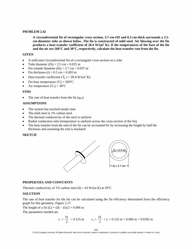
221 © 2018 Cengage Learning. All Rights Reserved. May not be scanned, copied or duplicated, or posted to a publicly accessible website, in whole or in part.
PROBLEM 2.42
A circumferential fin of rectangular cross section, 3.7-cm-OD and 0.3-cm-thick surrounds a 2.5-
cm-diameter tube as shown below. The fin is constructed of mild steel. Air blowing over the fin
produces a heat transfer coefficient of 28.4 W/(m2 K). If the temperatures of the base of the fin
and the air are 260°C and 38°C, respectively, calculate the heat transfer rate from the fin.
GIVEN
A mild steel circumferential fin of a rectangular cross section on a tube
Tube diameter (Dt) = 2.5 cm = 0.025 m
Fin outside diameter (Df) = 3.7 cm = 0.037 m
Fin thickness (t) = 0.3 cm = 0.003 m
Heat transfer coefficient ( ch ) = 28.4 W/(m2 K)
Fin base temperature (Ts) = 260°C
Air temperature (T) = 38°C
FIND
The rate of heat transfer from the fin (qfin)
ASSUMPTIONS
The system has reached steady state
The mild steel is 1% carbon steel
The thermal conductivity of the steel is uniform
Radial conduction only (temperature is uniform across the cross section of the fin)
The heat transfer from the end of the fin can be accounted for by increasing the length by half the
thickness and assuming the end is insulated
SKETCH
PROPERTIES AND CONSTANTS
Thermal conductivity of 1% carbon steel (k) = 43 W/(m K) at 20°C
SOLUTION
The rate of heat transfer for the fin can be calculated using the fin efficiency determined from the efficiency
graph for this geometry, Figure 2.17.
The length of a fin (L) = (Df – Dt)/2 = 0.006 m
The parameters needed are
ri = 2
tD = 0.125 m ro =
2
tD + L = 0.125 m + 0.006 m = 0.0185 m

222 © 2018 Cengage Learning. All Rights Reserved. May not be scanned, copied or duplicated, or posted to a publicly accessible website, in whole or in part.
32
2o i
tr r =
122
( )
c
o i
h
k t r r
320.003m
0.0815m 0.0125 m2
1222 28.4w/(m K)
43W/(m K) (0.003 m)(0.0185m 0.0125 m) = 0.176
2o
i
tr
r =
0.0185m 0.0015m
0.0125 m = 1.6
From Figure 2.17, the fin efficiency for these parameters is:
f = 98%
The rate of heat transfer from the fin is
qfin = f ch Afin (Ts – T) = f ch 2
22
2o i
tr r (Ts – T)
qfin = (0.98) 228.4W/(m K) 2 [(0.085 m + 0.0015 m)2 – (0.0125 m)2] (260°C – 38°C) = 9.46 W

223 © 2018 Cengage Learning. All Rights Reserved. May not be scanned, copied or duplicated, or posted to a publicly accessible website, in whole or in part.
PROBLEM 2.43
A turbine blade 6.3-cm-long, with cross-sectional area A = 4.6 10–4 m2 and perimeter P = 0.12 m, is
made of stainless steel (k = 18 W/(m K). The temperature of the root, Ts, is 482°C. The blade is
exposed to a hot gas at 871°C, and the heat transfer coefficient h̅ is 454 W/(m2 K). Determine the
temperature of the blade tip and the rate of heat flow at the root of the blade. Assume that the
tip is insulated.
GIVEN
Stainless steel turbine blade
Length of blade (L) = 6.3 cm = 0.063 m
Cross-sectional area (A) = 4.6 10–4 m2
Perimeter (P) = 0.12 m
Thermal conductivity (k) = 18 W/(m K)
Temperature of the root (Ts) = 482°C
Temperature of the hot gas (T) = 871°C
Heat transfer coefficient ( ch ) = 454 W/(m2 K)
FIND
(a) The temperature of the blade tip (TL)
(b) The rate of heat flow (q) at the roof of the blade
ASSUMPTIONS
Steady state conditions prevail
The thermal conductivity is uniform
The tip is insulated
The cross-section of the blade is uniform
One dimensional conduction
SKETCH
SOLUTION
(a) The temperature distribution in a fin of uniform cross-section with an insulated tip, from Table 2.1, is
s
= cosh[ ( )]
cosh( )
m L x
mL
where m = h P
k A =
2
4 2
454W/(m K)(0.12 m)
18W/(mK)(4.6 10 m ) = 81.1
1
m
= T – T

224 © 2018 Cengage Learning. All Rights Reserved. May not be scanned, copied or duplicated, or posted to a publicly accessible website, in whole or in part.
At the blade tip, x = L, therefore
L
s
= L
s
T T
T T =
cosh[ (0)]
cosh( )
m
mL =
1
cosh( )mL
TL = T + cosh( )
sT T
mL = 871°C +
o o482 C 871 C
1cosh 81.1 (0.063m)
m
= 866°C
(b) The rate of heat transfer from the fin is given by Table 2.1 to be
q = M tanh (m L)
where M = ch P k A s
M = 2 4 2454W/(m K)(0.12 m) 18W/(m K) (4.6 10 m ) (482°C – 871°C) = – 261 W
q = (– 261 W) tanh 1
81.1 (0.063 m)m
= – 261 W (out of the blade)
COMMENTS
In a real situation, the heat transfer coefficient will vary over the surface with the highest value near the
leading edge. But because of the high thermal conductivity of the blade, the temperature at any section will be
esentially uniform.

225 © 2018 Cengage Learning. All Rights Reserved. May not be scanned, copied or duplicated, or posted to a publicly accessible website, in whole or in part.
PROBLEM 2.44
To determine the thermal conductivity of a long, solid 2.5 cm diameter rod, one half of the rod
was inserted into a furnace while the other half was projecting into air at 27°C. After steady
state had been reached, the temperatures at two points 7.6 cm apart were measured and found to
be 126°C and 91°C, respectively. The heat transfer coefficient over the surface of the rod
exposed to the air was estimated to be 22.7 W/(m2 K). What is the thermal conductivity of the
rod?
GIVEN
A solid rod, one half inserted into a furnace
Diameter of rod (D) = 2.5 cm = 0.25 m
Air temperature (T) = 27°C
Steady state has been reached
Temperatures at two points 7.6 cm apart
T1 = 126°C
T2 = 91°C
The heat transfer coefficient ( ch ) = 22.7 W/(m2 K)
FIND
The thermal conductivity (k) of the rod
ASSUMPTIONS
Uniform thermal conductivity
One dimensional conduction along the rod
The rod approximates a fin of infinite length protruding out of the furnace
SKETCH
SOLUTION
This problem can be visualized as the following pin fin problem shown below
The fin is of uniform cross section, therefore Table 2.1 can be used. The temperature distribution for a fin of
infinite length, from Table 2.1, is
s
= e–mx
where m = ch P
kA =
2
2
ch D
k D
= 4 ch
kD
Substituting this into the temperature distribution and solving for k

226 © 2018 Cengage Learning. All Rights Reserved. May not be scanned, copied or duplicated, or posted to a publicly accessible website, in whole or in part.
s
= exp 4 ch
xkD
k = 2
4
lns
ch
Dx
at x = L L = TL – T = 91°C – 27°C = 64°C
s = TW – T = 126°C – 27°C = 99°C
L
s
= 64
99 = 0.6465
Therefore
k =
2
2
4 22.7w/(m K)
ln (0.6465)0.025
0.076m
= 110 W/(m K)
COMMENTS
Note that this procedure can only be used if the assumption of an infinite length fin is valid. Otherwise, the
location of the temperature measurements along the fin must be specified to determine the thermal
conductivity.

227 © 2018 Cengage Learning. All Rights Reserved. May not be scanned, copied or duplicated, or posted to a publicly accessible website, in whole or in part.
PROBLEM 2.45
Heat is transferred from water to air through a brass wall (k = 54 W/(m K)). The addition of
rectangular brass fins, 0.08-cm-thick and 2.5-cm-long, spaced 1.25 cm apart, is contemplated.
Assuming a water-side heat transfer coefficient of 170 W/(m2 K) and an air-side heat transfer
coefficient of 17 W/(m2 K), compare the gain in heat transfer rate achieved by adding fins to: (a)
the water side, (b) the air side, and (c) both sides. (Neglect temperature drop through the wall.)
GIVEN
A brass wall with brass fins between air and water
Thermal conductivity of the brass (k) = 54 W/(m K)
Fin thickness (t) = 0.08 cm = 0.0008 m
Fin length (L) = 2.5 cm = 0.025 m
Fin spacing (d) = 1.25 cm = 0.125 m
Water-side heat transfer coefficient ( cwh ) = 170 W/(m2 K)
Air-side heat transfer coefficient ( cah ) = 17 W/(m2 K)
FIND
Compare the heat transfer rate with fins added to
(a) the water side, q(a)
(b) the air side, q(b)
(c) both sides, q(c)
ASSUMPTIONS
The thermal resistance of the wall is negligible
Steady state conditions prevail
Constant thermal conductivity
One dimensional conduction
Heat transfer from the tip of the fins is negligible
SKETCH
SOLUTION
The fins are of uniform cross-section, therefore Table 2.1 may be used. To simplify the analysis, the heat
transfer from the end of the fin will be neglected. For a fin with adiabatic tip, the rate of heat transfer is
qf = M tanh (m L)
where M = ch PkA s = (2 ) ( )ch w k wt s = w 2 ch kt s
m = ch P
kA =
(2 )ch w
kwt =
2 ch
kt

228 © 2018 Cengage Learning. All Rights Reserved. May not be scanned, copied or duplicated, or posted to a publicly accessible website, in whole or in part.
The number of fins per square meter of wall is
2
number of fins
m =
1
(0.0133m/fin)1m width) = 75.2 fins/m2
Fraction of the wall area not covered by fins is
bare
n
A
A =
2
2
1m 75.2(1-m-width)(0.008m)
m
= 0.939 0.94
The rate of heat transfer from the wall with fins is equal to the sum of the heat transfer from the bare wall and
from the fins q = ch Abare s + (number of fins) [M tanh (m L)]
q = bare 75.2 tanh ( ) sc w s
s c
Mh A A mL
R
where Aw is the total base area, i.e., with fins removed.
Therefore, the thermal resistance of a wall with fins based on a unit of base area is
Rc = bare
1
75.2 tanh ( )W cw s
A MA h mL
A
For fins on the water side
w
s
M = 1-m-width
2170W/(m K)(2) 54W/(mK) (0.0008 m) = 3.832 W/K
wm =
22 170W/(m K)
54W/(m K)(.0008 m) = 88.72
1
m
tan h (ma L) = tanh 1
88.72m
(0.025 m) = 0.977
For fins on the air side
a
s
M = 1-m-width 217W(m K) (2) 54W/(mK) (0.0008) = 1.212 W/K
ma =
22 17W/(m K)
54W/(m K) (0.0008 m) = 28.05
1
m
tan h ma L = tan h 1
28.05m
(0.025 m) = 0.605
The thermal circuit for the problem is
The values of thermal resistances with and without fins are
(Rca)nofins= 1
w caA h =
2
1
17W/(m K)wA =
1
wA 0.0588 (m2 K)/W

229 © 2018 Cengage Learning. All Rights Reserved. May not be scanned, copied or duplicated, or posted to a publicly accessible website, in whole or in part.
(Rcw)nofins = 1
w cwA h =
2
1
170W/(m K)wA =
1
wA 0.00588 (m2 K)/W
(Rca)fins = 2 2
1
17 W/(m K)(0.94) 75.2 m 1.212W/K (0.605)wA =
1
wA 0.0141 (m2 K)/W
(Rcw)fins = 2 2
1
170 W/(m K)(0.94) 75.2 m 3.832 W/K (0.977)wA =
1
wA 0.00227 (m2 K)/W
(a) The rate of heat transfer with fins on the water side only is
q(a) = no fins fins( ) ( )ca cw
T
R R
( )a
w
q
A =
2(0.0588 0.00227)(m K)/W
T = 16.4 T W/(m2 K)
(b) The rate of heat transfer with fins on the air side only is
q(b) = fins no fins( ) ( )ca cw
T
R R
( )b
w
q
A =
2(0.0141 0.00588)(m K)/W
T = 50.1 T W/(m2 K)
(c) With fins on both sides, the rate of heat transfer is
q(c) = fins no fins( ) ( )ca cw
T
R R
( )c
w
q
A =
2(0.0141 0.00227)(m K)/W
T = 61.1 T W/(m2 K)
As a basis of comparison, the rate of heat transfer without fins on either side is:
w
q
A =
2(0.0588 0.00588)(m W)/K
T = 15.5 T W/(m2 K)
The following percent increase over the no fins case occurs
Case % Increase
(a) fins on water side 5.8
(b) fins on air side 223
(c) fins on both sides 294
COMMENTS
Placing the fins on the side with the larger thermal resistance, i.e., the air side, has a much greater effect on the
rate of heat transfer.
The small gain in heat transfer rate achieved by placing fins on the water side only would most likely not be
justified due to the high cost of attaching the fins.

230 © 2018 Cengage Learning. All Rights Reserved. May not be scanned, copied or duplicated, or posted to a publicly accessible website, in whole or in part.
PROBLEM 2.46
The wall of a liquid-to-gas heat exchanger has a surface area on the liquid side of
1.8 m2 (0.6m 3m) with a heat transfer coefficient of 255 W/(m2 K). On the other side of the heat
exchanger wall flows a gas, and the wall has 96 thin rectangular steel fins 0.5-cm-thick and 1.25-cm-
high [k = 3 W/(m K)]. The fins are 3-m-long and the heat transfer coefficient on the gas side is 57
W/(m2 K). Assuming that the thermal resistance of the wall is negligible, determine the rate of
heat transfer if the overall temperature difference is 38°C.
GIVEN
The wall of a heat exchanger has 96 fins on the gas side
Surface area on the liquid side (AL) = 1.8 m2 (0.6 m 3 m)
Heat transfer coefficient on the liquid side (hcL) = 255 W/(m2 K)
The wall has 96 thin steel fins 0.5-cm-thick and 1.25-cm-high
Thermal conductivity of the steel (k) = 3 W/(m K)
Fin length (w) = 3 m, Fin height (L) = 1.25 cm = 0.0125 m
Fin thickness (t) = 0.5 cm = 0.005 m
Heat transfer coefficient on the gas side (hcg) = 57 W/(m2 K)
The overall temperature difference (T) = 38°C
FIND
The rate of heat transfer (q)
ASSUMPTIONS
The thermal resistance of the wall is negligible
The heat transfer through the wall is steady state
The thermal conductivity of the steel is constant
SKETCH
SOLUTION
The heat transfer from a single fin can be calculated from Table 2.1 for a fin with convection from the tip
qf = M
sinh ( ) cosh ( )
cosh ( ) sinh ( )
c
c
hmL mL
mk
hmL mL
mk

231 © 2018 Cengage Learning. All Rights Reserved. May not be scanned, copied or duplicated, or posted to a publicly accessible website, in whole or in part.
where m = ch P
kA =
(2 2 )
( )
ch t w
k wt =
257W/(m K)(6m 0.01 m)
3W/(m K)(3m)(0.005 m) = 87.25
1
m
mL = 87.25 1
m (0.0125 m) = 1.091 and ch
mk=
2
1m
57W/(m K)
87.25 3W/(m K) = 0.2178
M = ch PkA s = 257 W/(m K) (6.01m) 3W/(mK) (3m)(0.005m) (Ts – Tg) = 3.926 (Ts – Tg)W/K
qf = 3.926( )W/Ks gT Tsinh(1.091) 0.2178cosh(1.091)
cosh(1.091) 0.2178sin h(1.091) = 3.395 (Ts – Tg) W/K
The rate of heat transfer on the gas side is the sum of the convection from the fins and the convection from the
bare wall between the fins. The bare area is
Abare = Awall – (number of fins) (Area of one fin)
= 1.8 m2 – (96 fins) [(3 m) (0.005 m)/fin] = 0.36 m2
The total rate of heat transfer to the gas is
qg = qbare + (number of fins) qf = cgh Abare (Ts – Tg) + 96(3.395) (Ts – Tg) W/K
qg = 2 257 W/(m K)(0.36m ) 96(3.395) (Ts – Tg) W/K = 346.4 (Ts – Tg) W/K =
s g
g
T T
R
The thermal resistance on the gas side is
Rg = 1
346.4 K/W = 0.002887 K/W
The thermal resistance on the liquid side is
RL = 1
cL wh A =
2 2
1
255W/(m K)(1.8 m ) = 0.002179 K/W
The rate of heat transfer is
q = tot
T
R =
g L
T
R R =
o38 C
(0.002887 0.002179)K/W = 7500 W
COMMENTS
Note that despite the much lower heat transfer coefficient on the gas side, the thermal resistance is no larger
than on the liquid side. This is the result of balancing the fin geometries which is a desirable situation from the
thermal design perspective. Adding fins on the liquid side would not increase the rate of heat transfer
appreciably.

232 © 2018 Cengage Learning. All Rights Reserved. May not be scanned, copied or duplicated, or posted to a publicly accessible website, in whole or in part.
PROBLEM 2.47
The top of a 30 cm I-beam is maintained at a temperature of 260°C, while the bottom is at 93°C.
The thickness of the web is 1.25 cm. Air at 260°C is blowing along the side of the beam so that h
= 40 W/(m2 K). The thermal conductivity of the steel may be assumed constant and equal to 43
W/(m K). Find the temperature distribution along the web from top to bottom and plot the
results.
GIVEN
A steel 12 in. I-beam
Temperature of the top (TL) = 260°C
Temperature of the bottom (Ts) = 93°C
Thickness of the web (t) = 1.25 cm
Air temperature (T) = 2600°C
Heat transfer coefficient ( ch ) = 40 W/(m2 K)
Thermal conductivity of the steel (k) = 43 W/(m K)
FIND
The temperature distribution along the web and the plot the results
ASSUMPTIONS
The thermal conductivity of the steel is uniform
The beam has reached steady state conditions
One dimensional through the web
The beam is very long compared to the web thickness
SKETCH
SOLUTION
The web of the I beam can be thought of as a fin with a uniform rectangular cross section and a fixed tip
temperature. From Table 2.1, the temperature distribution along the web is
s
=
sinh ( ) sinh[ ( )]
sinh ( )
L
s
m x m L x
mL
where = T – T

233 © 2018 Cengage Learning. All Rights Reserved. May not be scanned, copied or duplicated, or posted to a publicly accessible website, in whole or in part.
m = ch P
kA =
2( )ch w t
kwt =
2 ch
kt =
22 40 W/(m K)
43 /( K) 0.0125W m m = 12.2
1
m
mL = 3.666 & sinh (m L) = 19.54
s = Ts – T = 930C – 260°C = – 167°C L = TL – T = 0
Substitute these into the temperature distribution
( )
s
T x T = 0.0512 sinh [3.666 (1 – x)]
T(x) = 2600C – 15.353 sinh [3.66 (1 – x)]
This temperature distribution is plotted below
COMMENTS
In a real situation, the heat transfer coefficient is likely to vary with distance and this would require a
numerical solution.

234 © 2018 Cengage Learning. All Rights Reserved. May not be scanned, copied or duplicated, or posted to a publicly accessible website, in whole or in part.
PROBLEM 2.48
The handle of a ladle used for pouring molten lead is 30-cm-long. Originally the handle was
made of 1.9 1.25 cm mild steel bar stock. To reduce the grip temperature, it is proposed to
form the handle of tubing 0.15-cm-thick to the same rectangular shape. If the average heat
transfer coefficient over the handle surface is 14 W/(m2 K), estimate the reduction of the
temperature at the grip in air at 21°C.
GIVEN
A steel handle of a ladle used for pouring molten lead
Handle length (L) = 30 cm = 0.3 m
Original handle: 1.9 by 1.25 cm mild steel bar stock
New handle: tubing 0.15 cm thick with the same shape
The average heat transfer coefficient ( ch ) = 14 W/(m2 K)
Air temperature (T) = 21°C
FIND
The reduction of the temperature at the grip
ASSUMPTIONS
The lead is at the melting temperature
The handle is made of 1% carbon steel
The ladle is normally in steady state during use
The variation of the thermal conductivity is negligible
One dimensional conduction
Heat transfer from the end of the handle can be neglected
SKETCH
PROPERTIES
From Appendix 2, Tables 10 and 12
Thermal conductivity of 1% carbon steel = 43 W/(m K) at 20°C
Melting temperature of lead (Ts) = 601 K = 328°C
SOLUTION
The ladle handle can be treated as a fin with an adiabatic end as shown below
The temperature distribution in the handle, from Table 2.1 is
s
= cosh[ ( )]
cosh( )
m L x
mL
where = T(x) – T s = Ts – T = 328°C – 21°C = 307°C
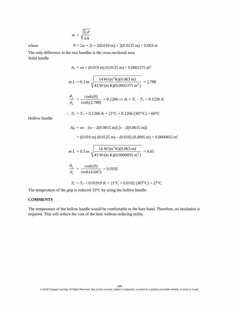
235 © 2018 Cengage Learning. All Rights Reserved. May not be scanned, copied or duplicated, or posted to a publicly accessible website, in whole or in part.
m = ch P
kA
where P = 2w + 2t = 2(0.019 m) + 2(0.0125 m) = 0.063 m
The only difference in the two handles is the cross-sectional area
Solid handle
As = wt = (0.019 m) (0.0125 m) = 0.0002375 m2
m L = 0.3 m 2
2
14 W/(m K)(0.063 m)
43 W/(m K)(0.0002375 m ) = 2.788
L
s
= cosh(0)
cosh(2.788) = 0.1266 L = TL – T = 0.1226 s
TL = T + 0.1266 s = 21°C + 0.1266 (307°C) = 60°C
Hollow handle
AH = wt – [w – 2(0.0015 m)] [t – 2(0.0015 m)]
= (0.019 m) (0.0125 m) – (0.016) (0.0095 m) = 0.0000855 m2
m L = 0.3 m 2
2
14 W/(m K)(0.063 m)
43 W/(m K)(0.0000855 m ) = 4.65
L
s
= cosh(0)
cosh(4.647) = 0.0192
TL = T + 0.01919 s = 21°C + 0.0192 (307°C) = 27°C
The temperature of the grip is reduced 33°C by using the hollow handle.
COMMENTS
The temperature of the hollow handle would be comfortable to the bare hand. Therefore, no insulation is
required. This will reduce the cost of the item without reducing utility.

236 © 2018 Cengage Learning. All Rights Reserved. May not be scanned, copied or duplicated, or posted to a publicly accessible website, in whole or in part.
PROBLEM 2.49
A 0.3-cm-thick aluminum plate has rectangular fins 0.16 0.6 cm, on one side, spaced 0.6 cm
apart. The finned side is in contact with low pressure air at 38°C and the average heat transfer
coefficient is 28.4 W/(m2 K). On the unfinned side water flows at 93°C and the heat transfer
coefficient is 284 W/(m2 K). (a) Calculate the efficiency of the fins
(b) calculate the rate of heat transfer per unit area of wall and (c) comment on the design if the
water and air were interchanged.
GIVEN
Aluminum plate with rectangular fins on one side
Plate thickness (D) = 0.3 cm = 0.003 m
Fin dimensions (t L) = 0.0016 m 0.006 m
Fin spacing (s) = 0.006 m apart
Finned side
Air temperature (Ta) = 38°C
Heat transfer coefficient ( ah ) = 28.4 W/(m2 K)
Unfinned side
Water temperature (Tw) = 93°C
Heat transfer coefficient ( wh ) = 284 W/(m2 K)
FIND
(a) The fin efficiency (f)
(b) Rate of heat transfer per unit wall area (q/Aw)
(c) Comment on the design if the water and air were interchanged
ASSUMPTIONS
Width of fins is much longer than their thickness
The system has reached steady state
The thermal conductivity of the aluminum is constant
SKETCH
PROPERTIES AND CONSTANTS
From Appendix 2, Table 12
The thermal conductivity of aluminum (k) = 238 W/(m K) at 65°C
SOLUTION
(a) The fin efficiency is defined as the actual heat transfer rate divided by the rate of heat transfer if the entire
fin were at the wall temperature. Since the fin is of uniform cross section,
Table 2.1 can be used to find an expression for the heat transfer from a fin with a convection from the tip

237 © 2018 Cengage Learning. All Rights Reserved. May not be scanned, copied or duplicated, or posted to a publicly accessible website, in whole or in part.
qf = M sinh ( ) cosh ( )
cosh ( ) ( )sinh ( )
ah
mk
a
mL mL
mL h mk mL
where m2 = ah P
kA =
2
( )
ah w
k wt =
2 ah
k t
M = ah PkA s = w 2 ah tk s
where s = Tsa – Ta
If the entire fin were at the wall temperature (Tsa) the rate of heat transfer would be
qf = ah Af (Tsa – Ta) = ah w(2L + t) (Tsa – Ta)
The fin efficiency is f = f
f
q
q =
sinh ( ) cosh ( )
cosh ( ) sinh ( )
(2 ) ( )
a
a
h
mk
h
mk
a sa a
mL mLM
mL mL
h w L t T T
m = 2 ah
kt =
22 28.4 W/(m K)
238 W/(m K)(0.0016 m) = 12.2
1
m
m L = 12.2 1
m (0.006 m) = 0.0733
M = w (Tsa – Ta) 2 22 28.4W/(m K) (0.0016 m) 238W/(m K) = 4.65 w (Tsa – Tw)s W/(mK)
ah
mk =
228.4 W/(m K)
112.2 238W/(m K)
m
= 0.0098
f =
2
2
sinh (0.0733) 0.00977cosh (0.0733)4.65W/(m K)
cosh (0.0733) 0.00977sinh (0.0733)
28.4 W/(m K) [(2)0.006 m 0.0016m] = 0.998
(b) The heat transfer to the air is equal to the sum of heat transfer from the fins and the heat transfer from the
wall area not covered by fins.
The number of fins per meter height is
1m (0.076 m/fin) = 131.6 fins
The wall area not covered by fins per m2 of total wall area is
Abare = 1 m2 – (131. 6 fins) 0.0016 m/fin (1 m width) = 0.789 m2
The surface area of the fins per m2 of wall area is
Afins = 131.6 fins (2(0.006 m) + 0.0016 m) (1 m width) = 1.79 m2
The rate of heat transfer to the air is
qa = ah Abare (Tsa – Ta) + ah f Afins (Tsa – Ta)
qa = ah (Abare + f Afins) (Tsa – Ta) = sa a
ca
T T
R
Therefore, the resistance to heat transfer on the air side (Ra) is

238 © 2018 Cengage Learning. All Rights Reserved. May not be scanned, copied or duplicated, or posted to a publicly accessible website, in whole or in part.
Rca = bare fins
1
( )a fh A A
total
1
ah A
The thermal circuit for the wall is shown below
The individual resistance based on 1 m2 of wall area are
Rcw = 1
w wh A =
2 2
1
238.7 W/(m K)(1m ) = 0.00419 K/W
Rk = w
D
kA =
2
0.003m
238.7 W/m K(1m ) = 0.0000126 K/W
Rca = bare fins
1
( )a fh A A =
2 2 2
0.003m
28.4 W/(m K) [0.789m (0.998)(1.79m ) = 0.0137 K/W
The rate of heat transfer through the wall is
q = tot
T
R = w a
cw k ca
T T
R R R =
93 38
(0.00419 0.0000126 0.0137)K/W
o oC C= 3072 W (per m2 of wall)
(c) Note that the air side convective resistance is by far the dominant resistance in the problem. Therefore, the
fins will enhance the overall heat transfer much less on the water side.
For fins on the water side
m =
22 283.7 W/(m K)
238W/(m K)(0.0016 m) = 38.6
1
m and m L = 38.6
1
m (0.006 m) = 0.2316
M = w (Tsw – Tw) 22 283.7 W/(m K) (0.0016 m)2 238 W/(mK) = 14.70 w (Tsw – Tw)W/m K
wh
mk
2283.7 W/(m K)
138.6 238 W/(mK)
m
= 0.0309
f = 2
sinh (0.2316) 0.0309cosh (0.2316)14.70 W/(m K)
cosh (0.2316) 0.0309sinh (0.2316)
283.7 W/(m K) [2 (0.006 m) 0.0016 m = 0.978
q = 1 1
(0.089 1.79)
w a
ca cw
T T
D
h k h
= o o
2
93 C 38 C
(0.0352 0.0000126 0.00139) (m K)/W
= 1502 W/m2
COMMENTS
The fins are most effective in the medium with the lowest heat transfer coefficient.
With no fins, the rate of heat transfer would be 1419 W/m2. Fins on the water side increase the rate of heat
transfer 6%. Fins on the air side increase the rate of heat transfer 116%. Therefore, installing fins on the water
side would be a poor design.

239 © 2018 Cengage Learning. All Rights Reserved. May not be scanned, copied or duplicated, or posted to a publicly accessible website, in whole or in part.
MULTIDIMENSIONAL STEADY STATE CONDUCTION
PROBLEM 2.50
Compare the rate of heat flow from the bottom to the top in the aluminum structure shown in
the sketch below with the rate of heat flow through a solid slab. The top is at –10°C, the bottom
at 0°C. The holes are filled with insulation which does not conduct heat appreciably.
GIVEN
The aluminum structure shown in the sketch below
Temperature of the top (TT) = – 10°C
Temperature of the bottom (TB) = 0°C
The holes are filled with insulation which does not conduct heat appreciably
FIND
Compare the rate of heat flow from the bottom to the top with the rate of heat flow through a solid slab
ASSUMPTIONS
The structure is in steady state
Heat transfer through the insulation is negligible
The thermal conductivity of the aluminum is uniform
The edges of the structure are insulated
Two dimensional conduction through the structure
SKETCH
PROPERTIES AND CONSTANTS
The thermal conductivity of aluminum (k) = 236 W/(m K) at 0°C
SOLUTION
Because of the symmetry of the structure, we can draw the flux plot for just one of the twenty-four equivalent
sections

240 © 2018 Cengage Learning. All Rights Reserved. May not be scanned, copied or duplicated, or posted to a publicly accessible website, in whole or in part.
(a) The total number of flow lanes in the structure, (M) = (12) (4) = (48). Each flow lane consists of 12
curvilinear squares (6 on top as shown, and 6 on bottom. Therefore, the shape factor is
S = 48
12
M
N = 4
The heat flow per meter, from Equation (2.85), is
q = kSToverall = 236 W/m K (4) (0°C – (– 10°C)) = 9440 W/m
The total rate of heat flow is
qo = q (length of structure) = 9440 W/m (3 m) = 28,320 W
(b) For a solid aluminum plate, the total heat flow from Equation (1.3), is
qTOT = Ak
t T =
(3m)(0.3m) 236 W/(mK)
0.05 (10 C) = 42,500 W
Therefore, the insulation filled tubes reduce the heat transfer rate by 33%.
COMMENTS
The shape factor was determined graphically and can easily be in error by 10%.
Also, the surface temperature will not be uniform in the insulated structure.

241 © 2018 Cengage Learning. All Rights Reserved. May not be scanned, copied or duplicated, or posted to a publicly accessible website, in whole or in part.
PROBLEM 2.51
Determine by means of a flux plot the temperatures and heat flow per unit depth in the ribbed
insulation shown in the accompanying sketch.
GIVEN
The sketch below
FIND
(a) The temperatures
(b) The heat flow per unit depth
ASSUMPTIONS
Steady state conditions
Two dimensional heat flow
The heat loss through the insulation is negligible
The thermal conductivity of the material is uniform
SKETCH
SOLUTION
The total number of heat flow lanes (M) = 11
The number of curvilinear squares per lane (N) = 8
Therefore, the shape factor is
S = 11
8
M
N = 1.38
The rate of heat transfer for unit depth is given by Equation 2.85
q = kST = (0.5 W/(m K)) (1.38) (100°C – 30°C) = 48.3 W/m

242 © 2018 Cengage Learning. All Rights Reserved. May not be scanned, copied or duplicated, or posted to a publicly accessible website, in whole or in part.
PROBLEM 2.52
Use a flux plot to estimate the rate of heat flow through the object shown in the sketch. The
thermal conductivity of the material is 15 W/(m K). Assume no heat is lost from the sides.
GIVEN
The shape of object shown in the sketch
The thermal conductivity of the material (k) = 15 W/(m K)
The temperatures at the upper and lower surfaces (30°C & 10°C)
FIND
The rate of heat flow through the object (By means of a flux plot)
ASSUMPTIONS
No heat is lost from the sides and ends
Uniform thermal conductivity
Two dimensional conduction
Steady state
SKETCH
SOLUTION
The flux plot is shown below
The number of heat flow lanes (M) = 2 10 = 20
The number of curvilinear squares in each lane (N) = 12
Therefore, the shape factor for this object is
S = 20 12M N = 1.67
The rate of heat transfer per unit length from Equation (2.85) is
q = kSToverall = [15 W/(m K)] (1.67) (20°C) = 500 W/m
The total rate of heat transfer is
qtot = qL = (500 W/m) (20 m) = 10,000 W

243 © 2018 Cengage Learning. All Rights Reserved. May not be scanned, copied or duplicated, or posted to a publicly accessible website, in whole or in part.
PROBLEM 2.53
Determine the rate of heat transfer per unit length from a 5-cm-OD pipe at 150°C placed
eccentrically within a larger cylinder of 85% Magnesia wool as shown in the sketch. The outside
diameter of the larger cylinder is 15 cm and the surface temperature is 50°C.
GIVEN
A pipe placed eccentrically within a larger cylinder of 85% Magnesia wool as shown in the sketch
Outside diameter of the pipe (Dp) = 5 cm = 0.05 m
Temperature of the pipe (Ts) = 150°C
Outside diameter of the larger cylinder (Do) = 15 cm = 0.15 m
Temperature of outer pipe (To) = 50°C
FIND
The rate of heat transfer per meter length (q)
ASSUMPTIONS
Two dimensional heat flow (no end effects)
The system is in steady state
Uniform thermal conductivity
SKETCH
PROPERTIES AND CONSTANTS
From Appendix 2, Table 11
The thermal conductivity of 85% Magnesia wool (k) = 0.059 W/(m K) (at 20°C).
SOLUTION
The rate of heat transfer can be estimated from a flux plot
The number of flow lanes (M) = 2 15 = 30
The number of squares per lane (N) = 5

244 © 2018 Cengage Learning. All Rights Reserved. May not be scanned, copied or duplicated, or posted to a publicly accessible website, in whole or in part.
Therefore, the shape factor is
S = 30
5
M
N = 6
Equation (2.85) can be used to find the rate of heat transfer per unit length
q = kST = kS(Ts – To) = [0.059 W/(m K)] (6) (150°C – 50°C) = 35.4 W/m
COMMENTS
This problem can also be solved analytically (see Table 2.2)
S = 2 2
1
2
4cosh
2
D d z
Dd
= 6.53
(z = the distance between the centers of the circular cross sections)
q = kST = 38.5 W/m
The answer from the graphical solution is 8% less than the analytical value.
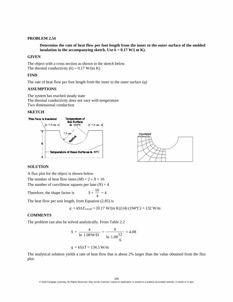
245 © 2018 Cengage Learning. All Rights Reserved. May not be scanned, copied or duplicated, or posted to a publicly accessible website, in whole or in part.
PROBLEM 2.54
Determine the rate of heat flow per foot length from the inner to the outer surface of the molded
insulation in the accompanying sketch. Use k = 0.17 W/( m K).
GIVEN
The object with a cross section as shown in the sketch below
The thermal conductivity (k) = 0.17 W/(m K)
FIND
The rate of heat flow per foot length from the inner to the outer surface (q)
ASSUMPTIONS
The system has reached steady state
The thermal conductivity does not vary with temperature
Two dimensional conduction
SKETCH
SOLUTION
A flux plot for the object is shown below
The number of heat flow lanes (M) = 2 8 = 16
The number of curvilinear squares per lane (N) = 4
Therefore, the shape factor is S = 16
4 = 4
The heat flow per unit length, from Equation (2.85) is
q = kSToverall = [0.17 W/(m K)] (4) (194°C) = 132 W/m
COMMENTS
The problem can also be solved analytically. From Table 2.2
S = π
ln 1.08W/D =
π
12ln 1.08
6
= 4.08
q = kST = 134.5 W/m
The analytical solution yields a rate of heat flow that is about 2% larger than the value obtained from the flux
plot.

246 © 2018 Cengage Learning. All Rights Reserved. May not be scanned, copied or duplicated, or posted to a publicly accessible website, in whole or in part.
PROBLEM 2.55
A long 1-cm-diameter electric copper cable is embedded in the center of a 25 cm square concrete
block. If the outside temperature of the concrete is 25°C and the rate of electrical energy
dissipation in the cable is 150 W per meter length, determine the temperatures at the outer
surface and at the center of the cable.
GIVEN
A long electric copper cable embedded in the center of a square concrete block
Diameter of the pipe (Dp) = 1 cm = 0.01 m
Length of a side of the block = 25 cm = 0.25 m
The outside temperature of the concrete (To) = 25°C
The rate of electrical energy dissipation ( /GQ L ) = 150 W/m
FIND
The temperatures at the outer surface (Ts) and at the center of the cable (Tc)
ASSUMPTIONS
Two dimensional, steady state heat transfer
Uniform thermal conductivities
SKETCH
PROPERTIES AND CONSTANTS
From Appendix 2, Table 11
The thermal conductivity of concrete (kb) = 0.128 W/(m K) at 20°C
From Appendix 2, Table 12
The thermal conductivity of copper (kc) = 396 W/(m K) at 63°C
SOLUTION
For steady state, the rate of heat transfer through the concrete block must equal the rate of electrical energy
dissipation. The heat transfer rate can be estimated with a flux plot of one quarter of the block:
The number of flow lanes (M) = 4 6 = 24
The number of squares per lane (N) = 10

247 © 2018 Cengage Learning. All Rights Reserved. May not be scanned, copied or duplicated, or posted to a publicly accessible website, in whole or in part.
Therefore, the shape factor is
S = M
N =
24
10 = 2.4
The rate of heat flow per unit length is given by Equation (2.85)
q = kbST = kbS(Ts – To) = GQ
L
Solving for the surface temperature of the cable
Ts = To +
G
b
Q
L
k S = 25°C +
150W/m
[0.128W/(m K)](2.4) = 513°C
From Equation (2.56) the temperature in the center of the cable is
Tc = Ts + 2
0
4
G
C
q r
k
Where Gq = heat generation per unit volume 2
0
Gq
r L
TC = Ts + 4
G
C
Q
L
k = 513°C +
150W/m
4 396W/(m K) = 513°C + 0.03°C 513°C
COMMENT
The thermal conductivity of the cable is quite large and therefore its temperature is essentially uniform.
The analytical solution for this geometry, given in Table 2.2, is
S = 2 π
WIn 0.8
D
= 2 π
25 cmIn 1.08
1cm
= 1.91
This would lead to a cable temperature of 639°C, 20% higher than the flux plot estimate. The high error is
probably due to the difficulty in drawing the flux plot close to the cable and may be improved by drawing a
larger scale flux plot is geometries that involve tight curves.

248 © 2018 Cengage Learning. All Rights Reserved. May not be scanned, copied or duplicated, or posted to a publicly accessible website, in whole or in part.
PROBLEM 2.56
A large number of 3.8 cm OD pipes carrying hot and cold liquids are embedded in concrete in an
equilateral staggered arrangement with center line 11.2 cm apart as shown in the sketch. If the
pipes in rows A and C are at 16°C while the pipes in rows B and D are at 66°C, determine the
rate of heat transfer per foot length from pipe X in row B.
GIVEN
A large number of pipes embedded in concrete as shown below
Outside diameter of pipes (D) = 3.8 cm
The temperature of the pipes in rows A and C = 16°C
The temperature of the pipes in rows B and D = 66°C
FIND
The rate of hat transfer per foot length from pipe X in row B
ASSUMPTIONS
Steady state, two dimensional heat transfer
Uniform thermal conductivity in the concrete
SKETCH
PROPERTIES AND CONSTANTS
From Appendix 2, Table 11
The thermal conductivity of concrete (kb) = 0.128 W/(m K) at 20°C
SOLUTION
A flux diagram for this problem is shown below

249 © 2018 Cengage Learning. All Rights Reserved. May not be scanned, copied or duplicated, or posted to a publicly accessible website, in whole or in part.
By symmetry, the total heat transfer from the tube X is four times that shown in the flux diagram.
The number of heat flow lanes (M) = 8 4 = 32
The number of curvilinear squares per lane (N) = 7
Therefore, the shape factor is
S = M
N =
32
7 = 4.6
The heat transfer per unit length from Table 2.2, from Equation (2.85) is
q KSToverall = [0.128 W/(m K)] (4.6) (660C –16°C) = 29.44 W/m

250 © 2018 Cengage Learning. All Rights Reserved. May not be scanned, copied or duplicated, or posted to a publicly accessible website, in whole or in part.
PROBLEM 2.57
A long 1-cm-diameter electric cable is imbedded in a concrete wall (k = 0.13 W/(m K)) which is 1
m*1 m, as shown in the sketch. If the lower surface is insulated, the surface of the cable is 100°C
and the exposed surface of the concrete is 25°C, estimate the rate of energy dissipation per meter
of cable.
GIVEN
A long electric cable imbedded in a concrete wall with cable diameter (D) = 1 cm = 0.01 m
Thermal conductivity of the wall (k) = 0.13 W/(m K)
Wall dimensions are 1 m by 1 m, as shown in the sketch below
The lower surface is insulated
The surface temperature of the cable (Ts) = 100°C
The temperature of the exposed concrete surfaces (To) = 25°C
FIND
The rate of energy dissipation per meter of cable (q/L)
ASSUMPTIONS
The system is in steady state
The thermal conductivity of the wall is uniform
Two dimensional heat transfer
SKETCH
SOLUTION
By symmetry, only half of the flux plot needs to be drawn
The number of heat flow lanes (M) = 2 14 = 28
The number of curvilinear squares per lane (N) = 6
Therefore, the shape factor is
S = M N = 28 6 = 4.7
For steady state, the rate of energy dissipation per unit length in the cable must equal the rate of heat transfer
per unit length from the cable which, from Equation (2.85), is
q = kS(Ts – To) = (0.13 W/(m K) (4.7)) (100°C – 25°C) = 46 W/m

251 © 2018 Cengage Learning. All Rights Reserved. May not be scanned, copied or duplicated, or posted to a publicly accessible website, in whole or in part.

252 © 2018 Cengage Learning. All Rights Reserved. May not be scanned, copied or duplicated, or posted to a publicly accessible website, in whole or in part.
PROBLEM 2.58
Determine the temperature distribution and heat flow rate per meter length in a long concrete
block having the shape shown below. The cross-sectional area of the block is square and the hole
is centered.
GIVEN
A long concrete block having the shape shown below
The cross-sectional area of the block is square
The hole is centered
FIND
(a) The temperature distribution in the block
(b) The heat flow rate per meter length
ASSUMPTIONS
The heat flow is two dimensional and in steady state
The thermal conductivity in the block is uniform
SKETCH
PROPERTIES AND CONSTANTS
From Appendix 2, Table 11
The thermal conductivity of concrete (kb) = 0.128 W/(m K) at 20°C
SOLUTION
The temperature distribution and heat flow rate may be estimated with a flux plot

253 © 2018 Cengage Learning. All Rights Reserved. May not be scanned, copied or duplicated, or posted to a publicly accessible website, in whole or in part.
(a) The temperature distribution is given by the isotherms in the flux plot.
(b) The number of flow lanes (M) = 2 21 = 42
The number of squares per lane (N) = 4
Therefore, the shape factor is
S = M
N =
42
4 = 10.5
From Equation (2.85), the rate of heat flow per unit length is
q = kST = [0.128 W/(m K)] (10.5) (40°C) = 54 W/m
COMMENTS
If the lower surface were not insulated, the shape factor from Table 2.2, would be
S = 2
WIn 1.08
D
= 14.8 q = 75.6 W/m
The rate of heat transfer with the insulation as calculated with the flux plot is about 29% less than the
analytical result without insulation. We would expect a reduction of slightly less than 25%.

254 © 2018 Cengage Learning. All Rights Reserved. May not be scanned, copied or duplicated, or posted to a publicly accessible website, in whole or in part.
PROBLEM 2.59
A 30-cm-OD pipe with a surface temperature of 90°C carries steam over a distance of 100 m.
The pipe is buried with its center line at a depth of 1 m, the ground surface is –6°C, and the
mean thermal conductivity of the soil is 0.7 W/(m K). Calculate the heat loss per day, and the
cost of this loss if steam heat is worth $3.00 per 106 kJ. Also, estimate the thickness of 85%
magnesia insulation necessary to achieve the same insulation as provided by the soil with a total
heat transfer coefficient of 23 W/(m2 K) on the outside of the pipe.
GIVEN
A buried steam pipe
Outside diameter of the pipe (D) = 30 cm = 0.3 m
Surface temperature (Ts) = 90°C
Length of pipe (L) = 100 m
Depth of its center line (Z) = 1 m
The ground surface temperature (Tg) = –6°C
The mean thermal conductivity of the soil (k) = 0.7 W/(m K)
Steam heat is worth $3.00 per 106 kJ
The heat transfer coefficient (hc) = 23 W/(m2 K) for the insulated pipe
FIND
(a) The heat loss per 24 hour day
(b) The value of the lost heat
(c) The thickness of 85% magnesia insulation necessary to achieve the same insulation
ASSUMPTIONS
Steady state conditions
Uniform thermal conductivity
Two dimensional heat transfer from the pipe
SKETCH
PROPERTIES AND CONSTANTS
From Appendix 2, Table 11
The thermal conductivity of 85% magnesia (ki) = 0.059 W/(m K) (at 20°C)
SOLUTION
(a) The shape factor for this problem, from Table 2.2, is

255 © 2018 Cengage Learning. All Rights Reserved. May not be scanned, copied or duplicated, or posted to a publicly accessible website, in whole or in part.
S = 1
2
2cosh
L
z
D
If z/L < 1
Note that the condition Z/L << 1 is satisfied in this problem.
S = –1
2 (100m)
2(1m)cosh
0.3m
= 243 m
From Equation (2.85), the rate of heat transfer is
q = kST = 0.7 W/(m K) (243 m) (90°C – (– 6°C))
q = 16,300 W (J/Ws) kI 3600s 24h
1000J h day
= 1.41 106 kJ/Day
(b) The cost of this heat loss is
Cost = 6
6
$3.001.41×10 kJ/day
10 kJ = $4.23/day
(c) The thermal circuit for the pipe covered with insulation is
The rate of heat loss from the pipe is
q = s g
ki c
T T
R R =
1
1 1ln
2 2
s g
o
i o c
T T
r
Lk r Lr h
= 16,300 W
16,300 W = 2 ( )
1 1ln
s g
o
i i o c
L T T
r
k r r h
=
2
2 (100m)[90 ( 6 )]
1 1ln
0.059W/(m K) 0.15m 23W/(m K)
o
o
L C
r
r
ln 0.15
or + 0.00257 1
or = 0.2183
By trial and error: ro = 0.184 m
Insulation thickness = ro – ri = 0.184 m – 0.15 m = 0.034 m = 3.4 cm
COMMENTS
The value of the heat loss per year is 365 $4.23 = $1544. Hence insulation will pay for itself quite rapidly.
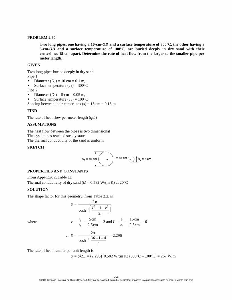
256 © 2018 Cengage Learning. All Rights Reserved. May not be scanned, copied or duplicated, or posted to a publicly accessible website, in whole or in part.
PROBLEM 2.60
Two long pipes, one having a 10-cm-OD and a surface temperature of 300°C, the other having a
5-cm-OD and a surface temperature of 100°C, are buried deeply in dry sand with their
centerlines 15 cm apart. Determine the rate of heat flow from the larger to the smaller pipe per
meter length.
GIVEN
Two long pipes buried deeply in dry sand
Pipe 1
Diameter (D1) = 10 cm = 0.1 m,
Surface temperature (T1) = 300°C
Pipe 2
Diameter (D2) = 5 cm = 0.05 m,
Surface temperature (T2) = 100°C
Spacing between their centerlines (s) = 15 cm = 0.15 m
FIND
The rate of heat flow per meter length (q/L)
ASSUMPTIONS
The heat flow between the pipes is two dimensional
The system has reached steady state
The thermal conductivity of the sand is uniform
SKETCH
PROPERTIES AND CONSTANTS
From Appendix 2, Table 11
Thermal conductivity of dry sand (k) = 0.582 W/(m K) at 20°C
SOLUTION
The shape factor for this geometry, from Table 2.2, is
S = 2 2
–1
2
– 1 –cosh
2
L r
r
where r = 1
2
r
r =
5cm
2.5cm = 2 and L =
2
1
r =
15cm
2.5cm = 6
S = –1
2π
36 – 1 – 4cosh
4
= 2.296
The rate of heat transfer per unit length is
q = SkT = (2.296) 0.582 W/(m K) (300°C – 100°C) = 267 W/m
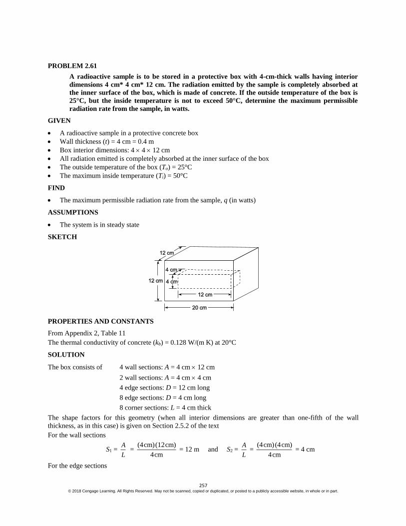
257 © 2018 Cengage Learning. All Rights Reserved. May not be scanned, copied or duplicated, or posted to a publicly accessible website, in whole or in part.
PROBLEM 2.61
A radioactive sample is to be stored in a protective box with 4-cm-thick walls having interior
dimensions 4 cm* 4 cm* 12 cm. The radiation emitted by the sample is completely absorbed at
the inner surface of the box, which is made of concrete. If the outside temperature of the box is
25°C, but the inside temperature is not to exceed 50°C, determine the maximum permissible
radiation rate from the sample, in watts.
GIVEN
A radioactive sample in a protective concrete box
Wall thickness (t) = 4 cm = 0.4 m
Box interior dimensions: 4 4 12 cm
All radiation emitted is completely absorbed at the inner surface of the box
The outside temperature of the box (To) = 25°C
The maximum inside temperature (Ti) = 50°C
FIND
The maximum permissible radiation rate from the sample, q (in watts)
ASSUMPTIONS
The system is in steady state
SKETCH
PROPERTIES AND CONSTANTS
From Appendix 2, Table 11
The thermal conductivity of concrete (kb) = 0.128 W/(m K) at 20°C
SOLUTION
The box consists of 4 wall sections: A = 4 cm 12 cm
2 wall sections: A = 4 cm 4 cm
4 edge sections: D = 12 cm long
8 edge sections: D = 4 cm long
8 corner sections: L = 4 cm thick
The shape factors for this geometry (when all interior dimensions are greater than one-fifth of the wall
thickness, as in this case) is given on Section 2.5.2 of the text
For the wall sections
S1 = A
L =
(4cm)(12cm)
4cm = 12 m and S2 =
A
L =
(4cm)(4cm)
4cm = 4 cm
For the edge sections

258 © 2018 Cengage Learning. All Rights Reserved. May not be scanned, copied or duplicated, or posted to a publicly accessible website, in whole or in part.
S3 = 0.54 D = 0.54 (12 cm) = 6.48 cm and S4 = 0.54 D = 0.54 (4 cm) = 2.16 cm
For the corner sections
S5 = 0.15 L = 0.15 (4 cm) = 0.6 cm
Multiplying each shape factor by the number of elements having that shape factor and summing them
S = 4 S1 + 2 S2 + 4 S3 + 8 S4 + 8 S5
S = 4 (12 cm) + 2(4 cm) + 4(6.48 cm) + 8(2.16 cm) + 8(0.6 cm) = 104 cm
The rate of heat transfer is
q = kST = 0.128 W/(m K) (104 cm) (1m/100 cm) (50°C – 25°C) = 3.3 W
COMMENTS
The conductivity of the concrete was evaluated at 20°C while the actual temperature is between 50°C and
25°C. Therefore, the actual rate of heat flow may be slightly different than that calculated, but no better
property value is available in the text.

259 © 2018 Cengage Learning. All Rights Reserved. May not be scanned, copied or duplicated, or posted to a publicly accessible website, in whole or in part.
PROBLEM 2.62
A 15 cm-OD pipe is buried with its centerline 1.25 m below the surface of the ground
[k of soil is 0.35 W/(m K)]. An oil having a density of 800 kg/m3 and a specific heat of 2.1 kJ/(kg
K) flows in the pipe at 5.6 L/s. Assuming a ground surface temperature of 5°C and a pipe wall
temperature of 95°C, estimate the length of pipe in which the oil temperature decreases by
5.5°C.
GIVEN
An oil filled pipe buried below the surface of the ground
Pipe outside diameter (D) = 15 cm = 0.15 m
Depth of centerline (z) = 1.25 m
Thermal conductivity of the soil (k) = 0.35 W/(m K)
Specific gravity of oil (Sp. Gr.) = 0.8
Specific heat of oil (cp) = 2.1 kJ/(kg K)
Flows rate of oil m = 5.6 L/s= 0.0056 m3/s
The ground surface temperature (Ts) = 5°C
The pipe wall temperature (Tp) = 95°C
FIND
The length of pipe (L) in which the oil temperature decreases by 5.5°C
ASSUMPTIONS
Steady state condition
Two dimensional heat transfer
SKETCH
SOLUTION
The rate of heat flow from the pipe can be calculated using the shape factor from Table 2.2 for an infinitely
long cylinder
S = –1
2
2cosh
Z
D
=
–1
2π
2(1.25)cosh
0.15
= 1.79
The rate of heat transfer per unit length is given by Equation (2.85)
q = kSToverall = (0.35 W/(m K)) (1.79) (950C – 50C) = 56.4 W/m

260 © 2018 Cengage Learning. All Rights Reserved. May not be scanned, copied or duplicated, or posted to a publicly accessible website, in whole or in part.
The total heat loss required to decrease the oil by 5.5°C is
qt = m cp T = 0.0056 [m3/s] (2100 J/(kg K)) (5.5°C)*800 (kg/m3) = 51744 W
We can estimate the length of pipe in which the oil temperature drops 10°F by assuming the rate of heat loss
from the pipe per unit length is constant, then:
qt = qL L = tq
q =
51744
56.4 = 917.5 m
COMMENTS
The heat loss from the pipe will actually be less because as the oil temperature and therefore also the pipe
temperature decreases with distance from the inlet. This means the length will be slightly longer than the
estimate above. If the calculation is based on an arithmetic mean pipe temperature of 50°C, the estimated
length is 954 m about 4% more.
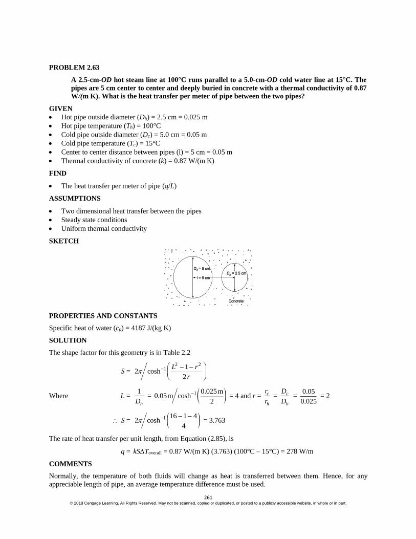
261 © 2018 Cengage Learning. All Rights Reserved. May not be scanned, copied or duplicated, or posted to a publicly accessible website, in whole or in part.
PROBLEM 2.63
A 2.5-cm-OD hot steam line at 100°C runs parallel to a 5.0-cm-OD cold water line at 15°C. The
pipes are 5 cm center to center and deeply buried in concrete with a thermal conductivity of 0.87
W/(m K). What is the heat transfer per meter of pipe between the two pipes?
GIVEN
Hot pipe outside diameter (Dh) = 2.5 cm = 0.025 m
Hot pipe temperature (Th) = 100°C
Cold pipe outside diameter (Dc) = 5.0 cm = 0.05 m
Cold pipe temperature (Tc) = 15°C
Center to center distance between pipes (l) = 5 cm = 0.05 m
Thermal conductivity of concrete (k) = 0.87 W/(m K)
FIND
The heat transfer per meter of pipe (q/L)
ASSUMPTIONS
Two dimensional heat transfer between the pipes
Steady state conditions
Uniform thermal conductivity
SKETCH
PROPERTIES AND CONSTANTS
Specific heat of water (cp) = 4187 J/(kg K)
SOLUTION
The shape factor for this geometry is in Table 2.2
S = 2 2
1 12 cosh
2
L r
r
Where L = 1
hD = 1 0.025m
0.05m cosh2
= 4 and r = c
h
r
r = c
h
D
D =
0.05
0.025 = 2
S = 1 16 1 42 cosh
4
= 3.763
The rate of heat transfer per unit length, from Equation (2.85), is
q = kSToverall = 0.87 W/(m K) (3.763) (100°C – 15°C) = 278 W/m
COMMENTS
Normally, the temperature of both fluids will change as heat is transferred between them. Hence, for any
appreciable length of pipe, an average temperature difference must be used.

262 © 2018 Cengage Learning. All Rights Reserved. May not be scanned, copied or duplicated, or posted to a publicly accessible website, in whole or in part.
PROBLEM 2.64
Calculate the rate of heat transfer between a 15-cm-OD pipe at 120°C and a 10-cm-OD pipe at
40°C. The two pipes are 330-m-long and are buried in sand [k = 0.33 W/(m K)] 12 m below the
surface (Ts = 25°C). The pipes are parallel and are separated by 23 cm (center to center)
distance.
GIVEN
Two parallel pipes buried in sand
Pipe 1
Outside diameter (D1) = 15 cm = 0.15 m
Temperature (T1) = 120°C
Pipe 2
Outside diameter (D2) = 10 cm = 0.1 m
Temperature (T2) = 40°C
Length of pipes (L) = 330 m
Thermal conductivity of the sand (k) = 0.33 W/(m K)
Depth below surface (d) = 1.2 m
Surface temperature (Ts) = 25°C
Center to center distance between pipes (s) = 23 cm = 0.23 m
FIND
The rate of heat transfer between the pipes (q)
ASSUMPTIONS
The thermal conductivity of the sand is uniform
Two dimensional, steady state heat transfer
SKETCH
SOLUTION

263 © 2018 Cengage Learning. All Rights Reserved. May not be scanned, copied or duplicated, or posted to a publicly accessible website, in whole or in part.
For the pipe-to-pipe heat transfer, the surface is not important since Z >> D. The shape factor for this
geometry, from Table 2.2, is
S = 2 2
1
2
1cosh
2
L r
r
where L = 2
1
r =
0.23m
0.05m = 4.6 and r = 1
2
r
r = 1
2
D
D =
15m
0.1m = 1.5
S = 2 2
1
2
(4.6) 1 (1.5)cosh
2(1.5)
= 2.541
The rate of heat transfer per unit length is
q
L = kST = 0.33 W/(m K) (2.541) (120°C – 40°C) = 67 W/m
For L = 330 m: q = 67 W/m (330 m) = 22,100 W
COMMENTS
Normally, the temperature of both fluids will change as heat is transferred between them. Hence, for any
appreciable length of pipe, an average temperature difference must be used.

264 © 2018 Cengage Learning. All Rights Reserved. May not be scanned, copied or duplicated, or posted to a publicly accessible website, in whole or in part.
Principles of Heat Transfer, 8th Edition
Chapter 2: Concept Review Questions
2.1 Consider steady-state heat conduction in a semi-infinite plate or slab of thickness L, a very long hollow cylinder, and a hollow sphere of inner radius ri and outer radius ro. Assuming uniform conductivity k in the plate, write the conduction equation and express the respective thermal resistance for each of the three geometries.
2.2 What is the primary purpose of adding fins to a heat transfer surface? Consider a plate separating two fluids, A and B, with respective convection heat transfer coefficients cAh and cBh such that cAh >> cBh . To what side of the plate surface should fins be added and why? In choosing the size of these fins, would you make them as long as the available space would permit? Why or why not?
© 2018 Cengage Learning Engineering. All Rights Reserved.

Principles of Heat Transfer, 8th Edition
Chapter 2: Concept Review Solutions
2.1 Consider steady-state heat conduction in a semi-infinite plate or slab of thickness L, a very long hollow cylinder, and a hollow sphere of inner radius ri and outer radius ro. Assuming uniform conductivity k in the plate, write the conduction equation and express the respective thermal resistance for each of the three geometries.
Semi-infinite plate or slab of thickness L: 02
2
=dx
Td
For heat flow from the hot side at TH to the cold side at TC the heat transfer rate is
th
CHk R
TTLT
kAq)( −
=∆
−= ,
where the thermal resistance is kAL
Rth = and A is the surface area of the plate.
Long hollow cylinder of radii ri and ro: 0=⎟⎠⎞⎜
⎝⎛
drdT
rdrd
For heat flow from the inside of the cylinder to the outside (Ti > To), the heat transfer rate is
th
oi
io
oik R
TTrr
TTLkq
)()ln()(
2−
=−
= π ,
where the thermal resistance is Lk
rrR io
th π2)ln(
= and L is the length of cylinder.
Hollow sphere of radii ri and ro: 01 2
2 =⎟⎠⎞⎜
⎝⎛
drdT
rdrd
r
For heat flow from the inside of the sphere to the outside (Ti > To), the heat transfer rate is
th
oi
io
oiiok R
TTrrTT
krrq)(
)()(
4−
=−−
= π ,
where the thermal resistance is krr
rrR
io
ioth π4
−= .
2.2 What is the primary purpose of adding fins to a heat transfer surface? Consider a plate separating two fluids, A and B, with respective convection heat transfer
© 2018 Cengage Learning Engineering. All Rights Reserved.

Principles of Heat Transfer, 8th Edition
coefficients cAh and cBh such that cAh >> cBh . To what side of the plate surface should fins be added and why? In choosing the size of these fins, would you make them as long as the available space would permit? Why or why not?
The primary purpose of adding fins to a heat transfer surface is to increase its surface area so that it can increase the rate of heating or cooling, or heat transfer enhancement. In explanation, consider a surface of area A that exchanges heat by convection with its surroundings (e.g. cooling air flow over a heat dissipating microelectronic processor) for which the heat transfer rate can be expressed as
TAhq cc ∆=
Thus, for fixed ∆T and ch , a higher heat transfer rate qc can be sustained by increasing the surface area A by adding fins. Another way to look at this problem is that by increasing A, the same heat transfer rate qc can be accommodated with a much smaller temperature difference ∆T. Such considerations are important for the design of many heat exchangers in chemical processing plants, waste-heat recovery systems, micro-electronics cooling, and solar thermal energy conversion.
The overall thermal resistance of the two fluids, A and B, and the plate separating them is given by
⎟⎠
⎞⎜⎝
⎛++⎟
⎠
⎞⎜⎝
⎛=++=
AhR
AhRRRR
cBplate
cAcBplatecAo
11
Thus, if cBcA hh >> then cAcB RR >> and if the plate thermal resistance is much smaller than either of the two convection resistances, fins should be added to side B of the plate so that RcB could be reduced.
In choosing the size of fins, optimization based on length of fin is not very useful because fin efficiency decreases with increasing fin length (fin efficiency is 100% for the trivial case of zero fin length). What is more important is the relative increase in the heat transfer surface area with the addition of fins, which have a reasonably high efficiency (relatively short fins). For this, the number of fins becomes more important and generally thin, slender, closely space fins provide the most benefit (compared to fewer and thicker fins).
© 2018 Cengage Learning Engineering. All Rights Reserved.