Embed Size (px)
Citation preview

Encoders & Resolvers:
How to Choose the Right Feedback Option
This White Paper summarizes the difference between encoder and resolver feedback technology, helping the reader understand which
type of motion control is right for their application.
Absolute Encoder Incremental Encoder Resolver

The spectrum of rotary position and speed feedback devices on the market is increasing in breadth on a daily basis. The question is no longer just whether you should go with an encoder or a resolver. The number of questions can be mind boggling. Beginning with “Should I go absolute or incremental?” Should I go magnetic or optical? There are other manufacturers out there that make capacitive and
inductive. Should I be considering them as well? Do I need commercial, industrial, heavy, extreme, or maximum duty systems? Answer all these questions, and it’s easy street right? Wrong. When it comes to resolvers, you need to know size, accuracy, mounting, speed(s), and electrical interface. With encoders, you need to know resolution, ac-curacy, mounting, output, and connection.
We have good news. Your application is your cheat sheet, and no one knows more about your application than you do. We will review each feedback option down to its core technology, and how it may apply to your application.We will also highlight some key specifications in a chart that will also allow you to cross reference the type of feedback device to your application. Let us get started.
Incremental EncodersIncremental encoders rely on external electronics to interpret the position based on the count of the events that occurred on that device. The outputs for incremental encoders can come in the form of a single square wave(A), phased square waves(A and B) to determine direction of rotation, or phased square waves and an index or one pulse per revolution (A, B, and Z). The concept of phasing square waves to determine rotational direction is often referred to as “quadrature”. The means of achieving an incremental signal are typically referred to as the encoder engines. The two primary encoder engine categories are optical and magnetic. In both engines, similar sensor alignment is performed to provide output compatibility.
In the optical design, light is generated by an LED and detected by a chip‐level sensor. Between the two is a code disc, typically made of glass, metal, or plastic. In an incremental encoder, the code disc is etched, coated, or punched (if metal) with a fine grating of similar lines around the circumference. In the magnetic design, there is a magnetic wheel or disk, a magneto‐resistive sensor, and a conditioning circuit. The disk or wheel is magnetized with several poles. The sensor converts the sinusoidal change in magnetic field to an electrical signal as the disk or wheel rotates. That electrical signal is multiplied, divided, or interpolated by the conditioning circuit to produce the desirable square wave output.
Incremental encoders continue to lead in the area of speed feedback with no signs of slowing. Incremental encod-ers are the most widely used of all rotary feedback devices. With the ease of solid state circuit and software design,
written/edited by the Dynapar Engineering Team
Encoders and Resolvers: How to Choose the Right Feedback Option
DYNAPAR • Experts in Rotary Feedback Solutions • 1675 N. Delany Rd. • Gurnee, IL 60031 • P: 1.800.873.8731 F: 1.847-662.6633 • E: [email protected] • www.dynapar.com
devices that accept incremental encoder input are widely available. You can find drives, panel meters, counters, and PC cards that interface with incremental encoders. Optical encoders can be found in office environment applications such as copiers, and industrial applications such as automated guided vehicles(AGV’s), magnetic encoders are typi-cally needed in harsh conditions where optical encoders may show significant performance decrease. These applica-tions can be over‐head cranes, off highway vehicles, and paper mills.
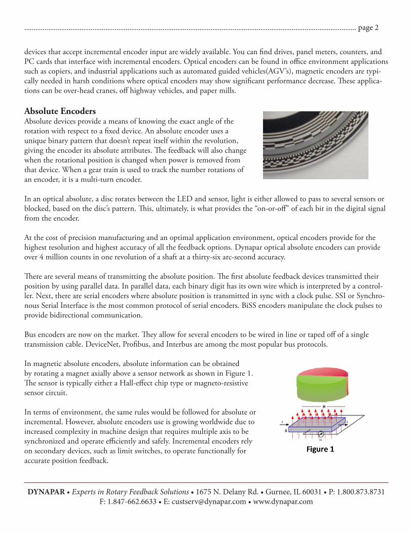
Absolute EncodersAbsolute devices provide a means of knowing the exact angle of the rotation with respect to a fixed device. An absolute encoder uses a unique binary pattern that doesn’t repeat itself within the revolution, giving the encoder its absolute attributes. The feedback will also change when the rotational position is changed when power is removed from that device. When a gear train is used to track the number rotations of an encoder, it is a multi‐turn encoder.
In an optical absolute, a disc rotates between the LED and sensor, light is either allowed to pass to several sensors or blocked, based on the disc’s pattern. This, ultimately, is what provides the “on-or-off” of each bit in the digital signal from the encoder.
At the cost of precision manufacturing and an optimal application environment, optical encoders provide for the highest resolution and highest accuracy of all the feedback options. Dynapar optical absolute encoders can provide over 4 million counts in one revolution of a shaft at a thirty‐six arc‐second accuracy.
There are several means of transmitting the absolute position. The first absolute feedback devices transmitted their position by using parallel data. In parallel data, each binary digit has its own wire which is interpreted by a control-ler. Next, there are serial encoders where absolute position is transmitted in sync with a clock pulse. SSI or Synchro-nous Serial Interface is the most common protocol of serial encoders. BiSS encoders manipulate the clock pulses to provide bidirectional communication.
Bus encoders are now on the market. They allow for several encoders to be wired in line or taped off of a single transmission cable. DeviceNet, Profibus, and Interbus are among the most popular bus protocols.
In magnetic absolute encoders, absolute information can be obtained by rotating a magnet axially above a sensor network as shown in Figure 1. The sensor is typically either a Hall-effect chip type or magneto-resistive sensor circuit.
In terms of environment, the same rules would be followed for absolute or incremental. However, absolute encoders use is growing worldwide due to increased complexity in machine design that requires multiple axis to be synchronized and operate efficiently and safely. Incremental encoders rely on secondary devices, such as limit switches, to operate functionally for accurate position feedback.
DYNAPAR • Experts in Rotary Feedback Solutions • 1675 N. Delany Rd. • Gurnee, IL 60031 • P: 1.800.873.8731 F: 1.847-662.6633 • E: [email protected] • www.dynapar.com
.................................................................................................................................................................................... page 2

Resolvers
Similar to encoders, resolvers are also electromechanical devices that convert mechanical motion into an electronic signal. However, unlike an encoder, a resolver transmits an analog signal rather than digital. It is essentially a rotary transformer with one primary winding and two secondary windings that are phased 90 mechanical degrees as shown in Figure 2. The resolver output requires control inputs and logic that can interpret analog signals.
One of the specifications in a resolver is its number of speeds. The output in Figure 3 is the output of a resolver with a single speed output. The number of speeds is equivalent to the number of amplitude modulated sinusoidal cycles in one revolution of the resolver. Multiple speed resolvers are achieved by increasing the number of magnetic poles in the rotor and stator equally. The maximum number of speeds is limited to the size of the resolver, and is typically done to increase the accuracy. However, a single speed resolver is essentially a single turn absolute device. By increasing the speeds of a resolver, the absolute information is lost. If space allows, mounting a single speed resolver on top of a multiple speed resolver will provide the higher accuracy and absolute benefits.
Resolvers lend themselves to maximum duty applications because of their simple component similarity to electric motors (windings, laminations, bearings, and carrier). The lack of optics and precision alignment increases shock and vibration capabilities. The lack of both optics and solid state electronics allows for use in high radiation environ-ments.
Resolvers have been time tested and proven, but the analog output limits the options that are available. The most popular use of resolvers is in permanent magnet brushless ac servo motors, military, aerospace applications.
The Bottom LineIn summary, the application should be the guide when deciding between resolver or encoder feedback. Control electronics and environment are the two biggest factors to consider-when both of these are answered, the choice becomes clear. On the next page, you’ll find quantified ratings that reflect the comments in this paper.
DYNAPAR • Experts in Rotary Feedback Solutions • 1675 N. Delany Rd. • Gurnee, IL 60031 • P: 1.800.873.8731 F: 1.847-662.6633 • E: [email protected] • www.dynapar.com
.................................................................................................................................................................................... page 3

Device Resolution Best Accuracy IP Rating Shock VibrationOptical
Incremental10,000 PPR Up to 2.5 arc-min IP67 50g1 20g2
Magnetic Incremental
2048 PPR NA3 IP67 30g 18g
Optical Absolute
222 cpr 36 arc-sec IP67 100g 10g
Magnetic Absolute
4096 cpr 0.6° IP68K 200g 20g
Resolver ∞ 2 arc-min IP654 200g5 40g
Table 1: Summary Chart6
1 Based on Northstar HD252 Based on Northstar HD253 Accuracy of Dynapar magnetic incremental is dependant upon the installation4 Housed5 Housed6 All values based on Dynapar feedback product line
Dynapar has the widest portfolio of encoders and resolvers in the industry and our experts are at your service to help you choose the right feedback option based on your application needs.
.................................................................................................................................................................................... page 4
DYNAPAR • Experts in Rotary Feedback Solutions • 1675 N. Delany Rd. • Gurnee, IL 60031 • P: 1.800.873.8731 F: 1.847-662.6633 • E: [email protected] • www.dynapar.com