Embed Size (px)
Citation preview

Product Information Rotary Encoders for the Elevator Industry
ENCODERS ESPECIALES PARA ASCENSORES
Rotary Encoders for the Elevator Industry
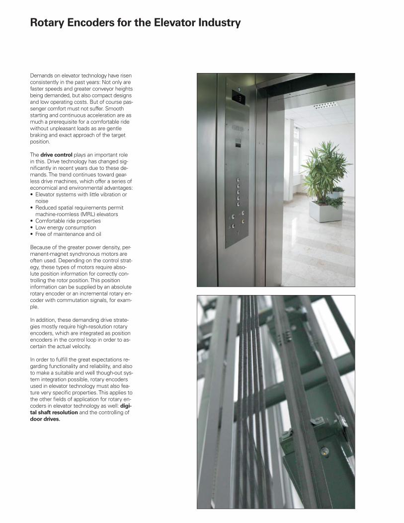
Demands on elevator technology have risen consistently in the past years: Not only are faster speeds and greater conveyor heights being demanded, but also compact designs and low operating costs. But of course pas-senger comfort must not suffer. Smooth starting and continuous acceleration are as much a prerequisite for a comfortable ride without unpleasant loads as are gentle braking and exact approach of the target position.
The drive control plays an important role in this. Drive technology has changed sig-nifi cantly in recent years due to these de-mands. The trend continues toward gear-less drive machines, which offer a series of economical and environmental advantages:
Elevator systems with little vibration or noiseReduced spatial requirements permit machine-roomless (MRL) elevatorsComfortable ride propertiesLow energy consumptionFree of maintenance and oil
Because of the greater power density, per-manent-magnet synchronous motors are often used. Depending on the control strat-egy, these types of motors require abso-lute position information for correctly con-trolling the rotor position. This position information can be supplied by an absolute rotary encoder or an incremental rotary en-coder with commutation signals, for exam-ple.
In addition, these demanding drive strate-gies mostly require high-resolution rotary encoders, which are integrated as position encoders in the control loop in order to as-certain the actual velocity.
In order to fulfi ll the great expectations re-garding functionality and reliability, and also to make a suitable and well though-out sys-tem integration possible, rotary encoders used in elevator technology must also fea-ture very specifi c properties. This applies to the other fi elds of application for rotary en-coders in elevator technology as well: digi-
tal shaft resolution and the controlling of door drives.
•
•
•••
Overview
Rotary Encoders for Drive Control in Elevators
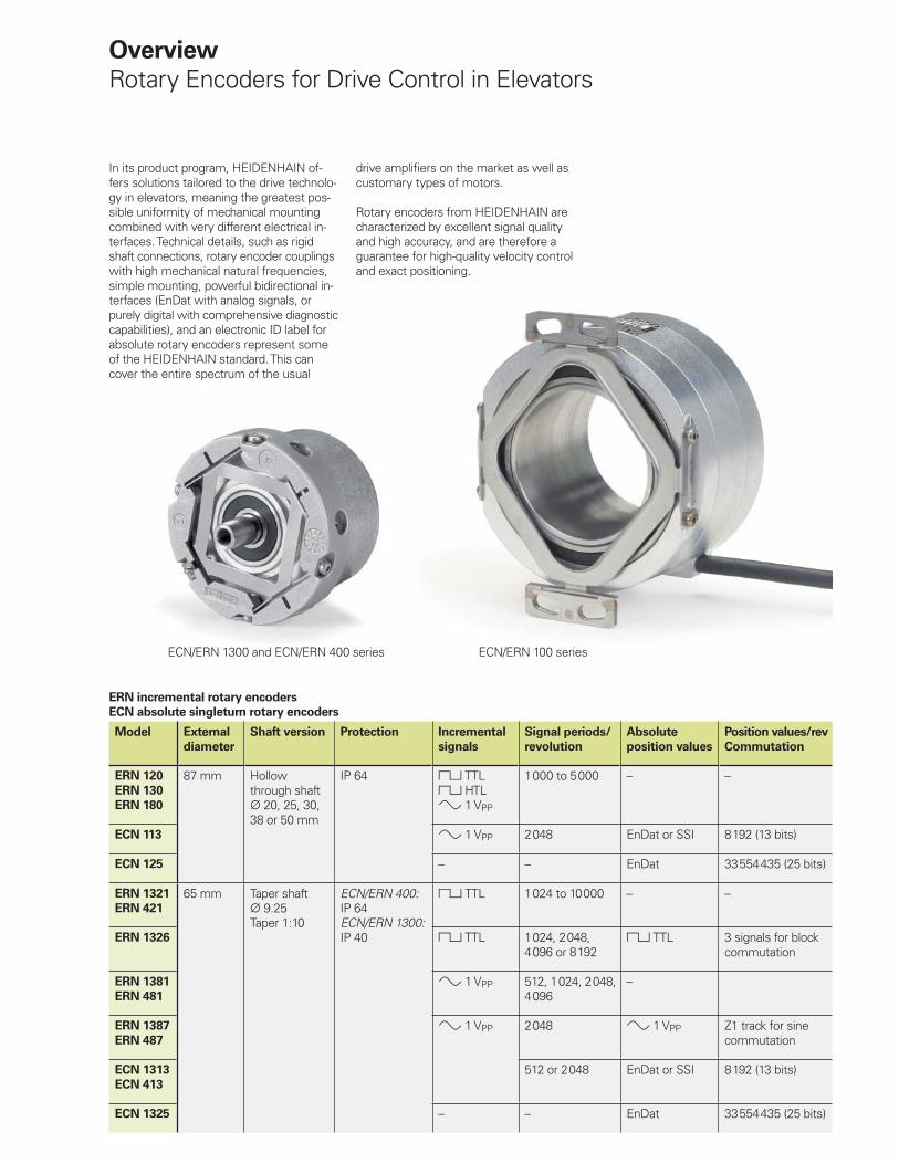
In its product program, HEIDENHAIN of-fers solutions tailored to the drive technolo-gy in elevators, meaning the greatest pos-sible uniformity of mechanical mounting combined with very different electrical in-terfaces. Technical details, such as rigid shaft connections, rotary encoder couplings with high mechanical natural frequencies, simple mounting, powerful bidirectional in-terfaces (EnDat with analog signals, or purely digital with comprehensive diagnostic capabilities), and an electronic ID label for absolute rotary encoders represent some of the HEIDENHAIN standard. This can cover the entire spectrum of the usual
ERN incremental rotary encoders
ECN absolute singleturn rotary encoders
Model External
diameter
Shaft version Protection Incremental
signals
Signal periods/
revolution
Absolute
position values
Position values/rev
Commutation
ERN 120
ERN 130
ERN 180
87 mm Hollowthrough shaft
20, 25, 30,38 or 50 mm
IP 64 TTL HTL 1 VPP
1 000 to 5 000 – –
ECN 113 1 VPP 2 048 EnDat or SSI 8 192 (13 bits)
ECN 125 – – EnDat 33 554 435 (25 bits)
ERN 1321
ERN 421
65 mm Taper shaft 9.25
Taper 1:10
ECN/ERN 400:IP 64ECN/ERN 1300:IP 40
TTL 1 024 to 10 000 – –
ERN 1326 TTL 1 024, 2 048, 4 096 or 8 192
TTL 3 signals for block commutation
ERN 1381
ERN 481
1 VPP 512, 1 024, 2 048, 4 096
–
ERN 1387
ERN 487
1 VPP 2 048 1 VPP Z1 track for sine commutation
ECN 1313
ECN 413
512 or 2 048 EnDat or SSI 8 192 (13 bits)
ECN 1325 – – EnDat 33 554 435 (25 bits)
drive amplifi ers on the market as well as customary types of motors.
Rotary encoders from HEIDENHAIN are characterized by excellent signal qualityand high accuracy, and are therefore a guarantee for high-quality velocity control and exact positioning.
ECN/ERN 1300 and ECN/ERN 400 series ECN/ERN 100 series
Rotary Encoders for Digital Shaft Resolution
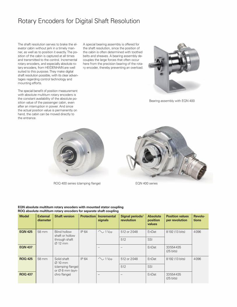
The shaft resolution serves to brake the el-evator cabin without jerk in a timely man-ner, as well as to position it exactly. The po-sition of the cabin is captured at all times and transmitted to the control. Incremental rotary encoders, and especially absolute ro-tary encoders, from HEIDENHAIN are well suited to this purpose. They make digital shaft resolution possible, with its clear advan-tages regarding control technology and mounting efforts.
The special benefi t of position measurement with absolute multiturn rotary encoders is the constant availability of the absolute po-sition value of the passenger cabin, even after an interruption in power. And since the actual position value is permanently on hand, the cabin can be moved directly to the entrance.
EQN absolute multiturn rotary encoders with mounted stator coupling
ROQ absolute multiturn rotary encoders for separate shaft coupling
Model External
diameter
Shaft version Protection Incremental
signals
Signal periods/
revolution
Absolute
position
values
Position values
per revolution
Revolu-
tions
EQN 425 58 mm Blind hollow shaft or hollow through shaft
12 mm
IP 64 1 VPP 512 or 2 048 EnDat 8 192 (13 bits) 4 096
512 SSI
EQN 437 – – EnDat 33 554 435(25 bits)
ROQ 425 58 mm Solid shaft 10 mm
(clamping fl ange) or 6 mm (syn-chro fl ange)
IP 64 1 VPP 512 or 2 048 EnDat 8 192 (13 bits) 4 096
512 SSI
ROQ 437 – – EnDat 33 554 435(25 bits)
A special bearing assembly is offered for the shaft resolution, since the position of the cabin is often determined with toothed belts and sheaves. A bearing assembly de-couples the large forces that often occur here from the precision bearing of the rota-ry encoder, thereby preventing an overload.
ROQ 400 series (clamping fl ange) EQN 400 series
Bearing assembly with EQN 400
ERO incremental rotary encoders for integration
ERN incremental rotary encoders
ECI absolute singleturn rotary encoders
EQI absolute multiturn encoders
Model External
diameter
Shaft version Protection Incremental
signals
Signal periods/
revolution
Absolute
position
values
Position values
per revolution
Revolu-
tions
ERO 1420 38.4 mm Hollowthrough shaft
4, 6 or 8 mm
IP 00 TTL 512, 1 000 or 1 024
– – –
ERN 1020
ERN 1030
ERN 1080
36.5 mm Blind hollow shaft 6 mm
IP 64 TTL HTL 1 VPP
100 to 3 600 – – –
ECI 1118 37 mm IP 20 1 VPP 16 EnDat 262 144 (18 bits) –
– –
EQI 1130 1 VPP 16 4 096
– –
Overview
Rotary Encoders for Door Drives
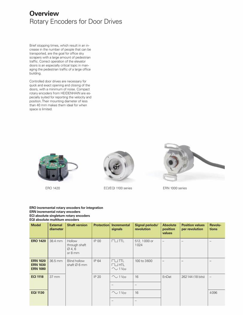
Brief stopping times, which result in an in-crease in the number of people that can be transported, are the goal for offi ce sky scrapers with a large amount of pedestrian traffi c. Correct operation of the elevator doors is an especially critical topic in man-aging the pedestrian traffi c of a large offi ce building.
Controlled door drives are necessary for quick and exact opening and closing of the doors, with a minimum of noise. Compact rotary encoders from HEIDENHAIN are es-pecially suited for reporting the velocity and position. Their mounting diameter of less than 40 mm makes them ideal for when space is limited.
ERO 1420 ECI/EQI 1100 series ERN 1000 series
�
���
�
������
���
����
���
��
�������� �
�����
���� ��
�
�
�
���
���
��
�� �
�
�
�
���
�
������
�
�����
���������������� ��������� ���!"�������� �����
����
�����������
#
�����
���
���
$��
�� � ���
����
%
� � %
� �
�
���
��
� �
��� ��
�� �
&���
"�
����
�
ERN 421, ERN 487, ECN 413, ECN 425 Product Information 10/2007
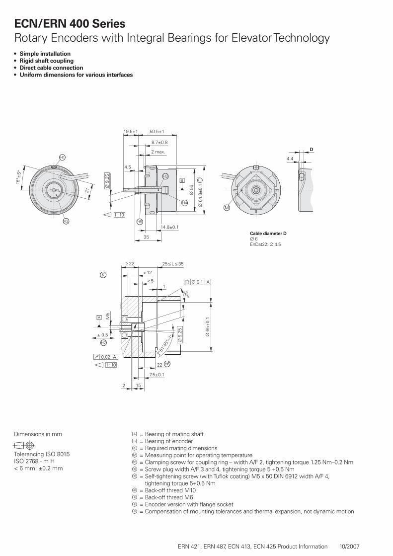
ECN/ERN 400 Series
Rotary Encoders with Integral Bearings for Elevator TechnologySimple installation
Rigid shaft coupling
Direct cable connection
Uniform dimensions for various interfaces
•
•
•
•
Dimensions in mm A = Bearing of mating shaftB = Bearing of encoderk = Required mating dimensionsm = Measuring point for operating temperatureÀ = Clamping screw for coupling ring – width A/F 2, tightening torque 1.25 Nm–0.2 NmÁ = Screw plug width A/F 3 and 4, tightening torque 5 +0.5 Nm = Self-tightening screw (with Tufl ok coating) M5 x 50 DIN 6912 width A/F 4,
tightening torque 5+0.5 Nmà = Back-off thread M10Ç = Back-off thread M6Å = Encoder version with fl ange socketÆ = Compensation of mounting tolerances and thermal expansion, not dynamic motion
Cable diameter D
¬ 6EnDat22: ¬ 4.5
ERN 421, ERN 487, ECN 413, ECN 425 Product Information 10/2007
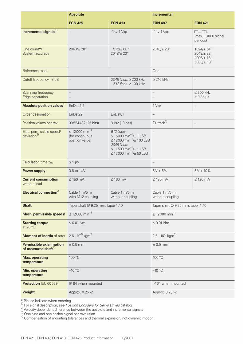
Absolute Incremental
ECN 425 ECN 413 ERN 487 ERN 421
Incremental signals1) – » 1 VPP » 1 VPP « TTL
(max. 10 000 signal periods)
Line count*/ System accuracy
2048/± 20“ 512/± 60“2048/± 20“
2048/± 20“ 1024/± 64“2048/± 32“4096/± 16“5000/± 13“
Reference mark – One
Cutoff frequency –3 dB – 2048 lines: ‡ 200 kHz 512 lines: ‡ 100 kHz
‡ 210 kHz –
Scanning frequencyEdge separation
––
––
† 300 kHz‡ 0.35 µs
Absolute position values1) EnDat 2.2 1 VPP –
Order designation EnDat22 EnDat01 –
Position values per rev 33 554 432 (25 bits) 8192 (13 bits) Z1 track3) –
Elec. permissible speed/deviation2)
† 12 000 min–1
(for continuousposition value)
512 lines:† 5 000 min–1/± 1 LSB† 12 000 min–1/± 100 LSB2048 lines:† 1 500 min–1/± 1 LSB† 12 000 min–1/± 50 LSB
–
Calculation time tcal † 5 µs –
Power supply 3.6 to 14 V 5 V ± 5% 5 V ± 10%
Current consumption
without load† 150 mA † 160 mA † 130 mA † 120 mA
Electrical connection2) Cable 1 m/5 m
with M12 couplingCable 1 m/5 mwithout coupling
Cable 1 m/5 mwithout coupling
Shaft Taper shaft ¬ 9.25 mm; taper 1:10 Taper shaft ¬ 9.25 mm; taper 1:10
Mech. permissible speed n † 12 000 min–1 † 12 000 min–1
Starting torque
at 20 °C† 0.01 Nm † 0.01 Nm
Moment of inertia of rotor 2.6 · 10-6 kgm2 2.6 · 10-6 kgm2
Permissible axial motion
of measured shaft4)
± 0.5 mm ± 0.5 mm
Max. operating
temperature
100 °C 100 °C
Min. operating
temperature
–10 °C –10 °C
Protection IEC 60 529 IP 64 when mounted IP 64 when mounted
Weight Approx. 0.25 kg Approx. 0.25 kg
* Please indicate when ordering1) For signal description, see Position Encoders for Servo Drives catalog 2) Velocity-dependent difference between the absolute and incremental signals3) One sine and one cosine signal per revolution4) Compensation of mounting tolerances and thermal expansion, not dynamic motion
���
�'�
������
��
#�
#
��
�
�'�
���
�
��
�'�
���(�����)����(��*� ��)�
��
�
���(��*� ��)�
�'���#��� �+�)�����
��
ERN 421, ERN 487, ECN 413, ECN 425 Product Information 10/2007
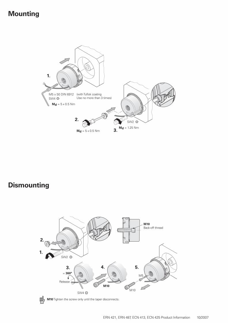
Mounting
Dismounting
Back-off thread
Release
M10 Tighten the screw only until the taper disconnects.
(with Tufl ok coatingUse no more than 3 times)
�
�
��
�
�
ERN 421, ERN 487, ECN 413, ECN 425 Product Information 10/2007
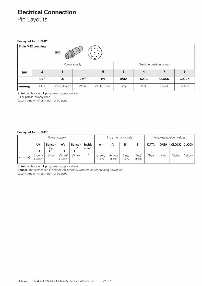
8-pin M12 coupling
Power supply Absolute position values
2 8 1 5 3 4 7 6
UP1)
UP 0 V1)
0 V DATA DATA CLOCK CLOCK
Blue Brown/Green White White/Green Gray Pink Violet Yellow
Shield on housing; UP = power supply voltage1) For parallel supply linesVacant pins or wires must not be used!
Pin layout for ECN 425
Power supply Incremental signals Absolute position values
UP Sensor
UP
0 V Sensor
0 VInside
shield
A+ A– B+ B– DATA DATA CLOCK CLOCK
Brown/Green
Blue White/Green
White / Green/Black
Yellow/Black
Blue/Black
Red/Black
Gray Pink Violet Yellow
Shield on housing; UP = power supply voltageSensor: The sensor line is connected internally with the corresponding power line.Vacant pins or wires must not be used!
Pin layout for ECN 413
Electrical Connection
Pin Layouts
��� �������� ���������� ����+�� ,�-����. !��/��-��� �0��1����� �������� ! ������"� *���2���3��� *���2���3� ��4 #�������5�6-��/��-����/�
###�$�%���$�%����
587 717-22 · 5 · 10/2007 · F&W · Printed in Germany · Subject to changes without notice
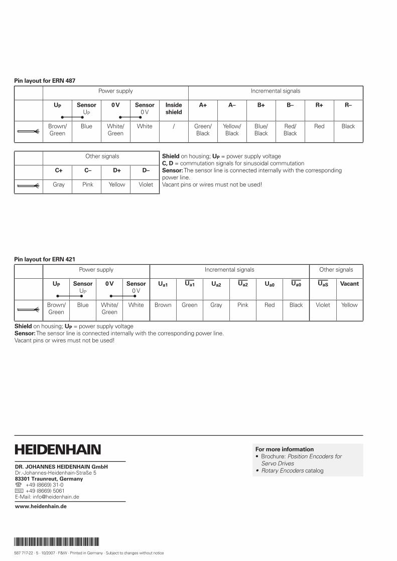
Power supply Incremental signals
UP Sensor
UP
0 V Sensor
0 VInside
shield
A+ A– B+ B– R+ R–
Brown/Green
Blue White/Green
White / Green/Black
Yellow/Black
Blue/Black
Red/Black
Red Black
Other signals Shield on housing; UP = power supply voltageC, D = commutation signals for sinusoidal commutationSensor: The sensor line is connected internally with the correspondingpower line.Vacant pins or wires must not be used!
C+ C– D+ D–
Gray Pink Yellow Violet
Pin layout for ERN 487
Power supply Incremental signals Other signals
UP Sensor
UP
0 V Sensor
0 VUa1 Ua2 £ Ua0 ¤ ¥ Vacant
Brown/Green
Blue White/Green
White Brown Green Gray Pink Red Black Violet Yellow
Shield on housing; UP = power supply voltageSensor: The sensor line is connected internally with the corresponding power line.Vacant pins or wires must not be used!
Pin layout for ERN 421
For more information
Brochure: Position Encoders forServo DrivesRotary Encoders catalog
•
•

Calle 49 Nº 5764 - Villa Ballester (B1653AOX) - Prov. de Buenos Aires - ARGENTINATel: (+54 11) 4768-4242 / Fax: (+54 11) 4849-1212Mail: [email protected] / Web: www.nakase.com.ar
Representante oficial de:
[Argentina – Bolivia – Chile – Colombia - Costa Rica – Ecuador - El Salvador – Guatemala – Honduras – Nicaragua – Panamá – Paraguay – Perú -
República Dominicana – Uruguay – Venezuela.]