Embed Size (px)
Citation preview
;-,
~)
BOOK 4: WELDING
t!2NBRIDGE
Related Standards
Requirements
Section
STANDARDS
Subject
Inspection
Canada Canadian Standards Association (CSA): • CSA Z662 - Oil and Gas Pipeline Systems
Canadian General Standards Board (CGSB):
02·02·06 Subject Number
• CAN/CGSB 48.9712 - Nondestructive Testing; Qualification and Certification of Personnel
United States American Petroleum Institute (API): • ANSI/API Std 1104 - Welding of Pipelines and Related
Facilities, Section 9
American Society for Non-destructive Testing (ASNT) • ASNT SNT-TC-IA - Nondestructive Testing
All welds must be nondestructively inspected in accordance with CSA Z662 (CAN), or API Std 1104, Section 9 (USA).
Workers must be aware of company policies concerning weld inspection to ensure standards are met.
Use contractors for: • magnetic particle inspection (MPI)
. • ultrasonic inspection (except to determine wall thickness)-• . radiographic inspection
1 + 1 CAN ................................ :. Contractors who are retained to perfonm nondestructive examination (NDE) must be hired directly by the company and must not be subcontracted through a second or third party.
Contractors must submit a written procedure describing the nondestructive testing method that includes as a minimum: • equipment used • calibration of the equipment • how to use the equipment
Qualification 1+1 CAN ... - ......................... Contractor personnel establishing inspection procedures or
techniques, scanning weldments, or interpreting results must be qualified to Level II or Level III in accordance with CAN/CGSB 48.9712-2000.
Juty 1,2009 Page 1 of 3

02-02-06 Inspection
= USA ...... .
Page2of3
BOOK4
Contractor personnel establishing inspection procedures or techniques, scanning weldments or interpreting results must be qualified to Level II or Level III in accordance with ASNT RP SNT-TC-IA.
Visual Inspection Observe the welding process to ensure the weld is completed according to the qualified procedure.
Fillet Welds For all welding on in-service pipe, inspect the weld for defects using MPI (a) immediately after completing the weld, and (b) at least 12 hrs after completing the weld. IfMPI identifies crack indications, complete ultrasonic inspection on all suspected areas.
Any undercut must be blended out and the area re-examined. Cracks, regardless of length, are defects that must be repaired (see Book 3: Pipeline Facilities, Tab 06 Pipe Repair and Modification).
NOTE: Exceptions to the 12-hr wait for branch connections reinforced with a saddle or split tee (see below) and in special circumstances must be' approved by regional management.
When adding a branch connection that will be reinforced with a saddle or split tee, the weld between the branch and the mainline can be inspected immediately after welding. The 12-hr waiting period must be observed b~fore nondestructive examination of the fillet welds between the branch and the reinforcement and between the run pipe and the reinforcement
Magnetic Particle Inspection Use magnetic particle inspection to check: • . fillet welds • nozzle welds • sleeve long-seam welds • longitudinal welds on pipe (manufacturers' welds)
NOTE: For more information, see 02-03-03 Magnetic Particle inspeclion of Fillel Welds.
July 1,2009

~ \ J
BOOK 4
Records'
Ultrasonic Inspection Use ultrasonic inspection to: • evaluate pipe wall thickness • evaluate internal corrosion • examine fillet welds • examine nozzle welds
02-02-06 Inspection
• examine longitudinal welds on pipe (manufacturers' welds)
NOTE: For more information, see 02-03-04 Ultrasonic Inspection of Fillet Welds.
Radiographic Inspection (X-Ray) Use radiographic inspection (or x-ray) to examine:
• butt welds
NOTE: For more information, see CSA 2662 (CAN) and ANSI!API Std 1104 (USA).
NOTE: In Canada, ultrasonic inspection may be used as an alternative to radiographic inspection at the company's discretion.
Defects Welds that exceed the defect acceptance criteria of CSA 2662 (CAN) or ANSI! API Std 1104 (USA) must be repaired or removed (see 02-02-04 Defect Repair).
Nondestructive Testing Report Record the results of ultrasonic and magnetic particle inspections of fillet welds using the Nondestructive Testing Report.
Retain all Nondestructive Testing Reports permanently in the PLM Activity Reporting database.
X-Ray Inspection of Girth Welds Form Record the results of radiographic inspection of butt welds using the X-Ray Inspection of Girth Welds form.
- USA .................................. Retain all X-Ray Inspection of Girth Welds forms permanently in the PLM Activity Reporting database.
July 1. 2009 Page 3 of 3

Welding
1. Scope of Work
The scope of this section is to ensure the required Welding Procedure Qualification and Welding
Procedure Specification (WPS) are met and the necessa ry Welder Performance Qualifications are
adequate and current. All regulatory requirements are noted below in Section 2. Enbridge O&MP Book
4 - Welding is the primary standard and includes incorporation of other regulatory requirements.
The pipe replacement section will be welded into the existing pipeline using pre-approved Company
WPS. Welders currently qualified to the WPS will perform the welding required. Two WPS's will be used
as part of the welding repair process. Enbridge procedure to be determined will be used as the WPS for
welding 2" branch connections on the existing line to allow thorough drain-up of any remaining product
in the line and venting during the welding process. Enbridge procedure UB-7S will be used as the WPS
for butt weld tie-ins of replacement pipe to the existing pipeline. Both procedures are manual, shielded
metal arc weld (SMAW) welding procedures. The SMAW process uses consumable electrodes coated in
flux to lay the weld. The WPS's are included as attachments to this section of the work plan.
At the completion of the respective replacement pipe segment installation welding processes, the
integrity of all welds will be verified by a non-destructive testing (NOT). The 2" drain connections will be
tested by Magnetic Particle Inspection (MPI) . The requirements for the MPI process are addressed in
Enbridge O&MP Book 4, Section 02-02-06 Inspection and Section 02-03-03 Performing Magnetic Particle
Inspection of Fillet Welds. The butt welds will be inspected by radiography. The radiographic process is
addressed in Enbridge O&MP Book 4, Section 02-02-06 Inspection. All NOT will be performed by
independent, third party Contractors who have the required, qualified NOT procedures and technical
personnel to perform the respective NOT process.
2. Regulatory Requirements
API 1104 Welding of Pipelines and Related Facilities, 19t h Edition
ASME Section IX of the Boiler and Pressure Vessel Code
CFR Title 49, Part 195:
§ 195.202 Compliance with specifications or standards.
Each pipeline system must be constructed in accordance with comprehensive written specifications or standards that are consistent with the requirements of this part.
§ 195.206 Material inspection.
No pipe or other component may be installed in a pipeline system unless it has been visually inspected at the site of installation to ensure that it is not damaged in a manner that could impair its strength or reduce its serviceability.
195.214 Welding procedures.
(a) Welding must be performed by a qualified welder in accordance with welding procedures qualified under Section 5 of API 1104 or Section IX of the ASME Boiler and Pressure Vessel Code (incorporated by reference, see § 195.3) . The quality of the test welds used to qualify the welding procedure shall be determined by destructive testing .
(b) Each welding procedure must be recorded in detail, including the results of the qualifying tests. This record must be retained and followed whenever the procedure is used.
§ 195.222 Welders: Qualification of welders.
(a) Each welder must be qualified in accordance with section 6 of API 1104 (incorporated by reference, see §195.3) or section IX of the ASME Boiler and Pressure Vessel Code, (incorporated by reference, see §195.3) except that a welder qualified under an earlier edition than listed in §195.3 may weld but may not re-qualify under that earlier edition.
(b) No welder may weld with a welding process unless, within the preceding 6 calendar months, the welder has-
(1) Engaged in welding with that process; and
(2) Had one welded tested and found acceptable under section 9 of API 1104 (incorporated by reference, see §195.3).
§ 195_224 Welding: Weather.
Welding must be protected from weather conditions that would impair the quality of the completed weld.
§ 195.226 Welding: Arc burns_
(a) Each arc bum '!lust be repaired .
(b) An arc bum may be repaired by completely removing the notCh by grinding, if the grinding does not reduce the remaining wall thickness to less than the minimum thickness required by the tolerances in the specification to which the pipe is manufactured . If a notch is not repairable by grinding. a cylinder of the pipe containing the entire notch must be removed .
(c) A ground may not be welded· to the pipe or fitting that is being welded .
§ 195.228 Welds and welding Inspection: Standards of acceptability.
(a) Each weld and welding must be inspected to insure compliance with the requirements of this subpart. Visual inspection must be supplemented by nondestructive testing .
(b) The acceptability of a weld is determined according to the standards in Section 9 of API 1104. However, if a girth weld is unacceptable under those standards for a reason other than a crack, and if Appendix A to API 1104 (incorporated by reference, see §195.3) applies to the weld, the acceptability of the weld may be determined under that appendix.
§ 195.230 Welds: Repair or removal of defects.

(a) Each weld that is unacceptable under §195.228 must be removed or repaired. Except for welds on an offshore pipeline being installed from a pipelay vessel, a weld must be removed if it has a crack that is more than 8 percent of the weld length.
(b) Each weld that is repaired must have the defect r~moved down to sound metal and the segment to be repaired must be preheated if conditions exist which would adversely affect the quality of the weld repair. After repair, the segment of the weld that was repaired must be inspected to ensure its acceptability.
(c) Repair of a crack, or of any defect in a previously repaired area must be in accordance with written weld repair procedures that have been qualified under §195.214. Repair procedures must provide that the minimum mechanical properties specified for the welding procedure used to make the original weld are met upon completion of the final weld repair.
§ 195.234 Welds: Nondestructive testing.
(a) A weld may be nondestructively tested by any process that will clearly indicate any defects that may affect the integrity of the weld.
(b) Any nondestructive testing of welds must be performed-
(1) In accordance with a written set of procedures for nondestructive testing; and
(2) With personnel that have been trained in the established procedures and in the use of the equipment employed in the testing.
(c) Procedures for the proper interpretation of each weld inspection must be established to ensure the acceptability of the weld under §195.228.
(d) During construction, at least 10 percent of the girth welds made by each welder during each welding day must be nondestructively tested over the entire circumference of the weld.
(e) All girth welds installed each day in the following locations must be nondestructively tested over their entire circumference, except that when nondestructive testing is impracticable for a girth weld , it need not be tested if the number of girth welds for which testing is impracticable does not exceed 10 percent of the girth welds installed that day: .
(1) At any onshore location where a loss of hazardous liquid could reasonably be expected to pollute any stream, river, lake, reservoir, or other body of water, and any offshore area;
(2) Within railroad or public road rights-of-way;
(3) At overhead road crossings and within tunnels;
(4) Within the limits of any incorporated subdivision of a State government; and
(5) Within populated areas, including, but not limited to, residential subdivisions, shopping centers, schools, designated commercial areas, industrial facilities, public institutions, and places of public assembly.
(I) When installing used pipe, 100 percent of the old girth welds must be nondestructively tested.
(g) At pipeline tie-ins, including tie-ins of replacement sections, 100 percent of the girth welds must be nondestructively tested .

',\ 3. Company Standards ~i
\. ) O&MP Book 4 - Welding
4. Exceptions to standards or specific site requirements - None

tilNBRIDGE Welding Procedure Specification Datasheet Application: Butt weld for maintenance welding of non-in-service pipe or fittings with and without notch toughness requirement to -46'C (-50'F) Codes: ASME Section IX, Compliant to CSA Z662, CFR 49 Parts 192 and 195 Inspection Standards: CAN: ASME B31.3; USA: API 1104
Material Qua lified ;5;API 5L Gr.X70; "CSA Z245 Gr.4S3, ASME IX PI(SI) Group 112/3 CEo ", 0.50
Datasheet No.: UB-75 Rev. : 0 WPS No.: UB-75 (rev 0)
(typical P I materials include SA 106, SA333, SA516-70, SA537CL2) - contact Pi".line Intellrity for other material substitutions Diameter Range Welding Process Polarity All SMA W, Manual DCRP (Electrode Positive) Wall Thickness Range 3.2 - 25.4 mm (0.125 - I in.) Preheat Temperature ~ 120'C (250'F)
Welding Position All Interpass Temperature ~ 120'C (250'F) and ;5;232'C (450' F)
Filler Metal E60 I 0 and ESO IS-C3 Postweld Heat Treatment NIA
• Preheat must be applied to an area of at least 2" on each side of the weld joint for the entire circumference prior to welding. • Preheating may be applied by oxy·fuel torch, propane torch, electrical induction coils or other method approved by Enbridge. • Preheat temperature must be checked using temperature indicating crayons, thermocouple pyrometers or other suitable method
approved by Enbridge to determine that the required preheat temperature is obtained prior to, and maintained during the welding operation.
Line Up Clamp Removal Internal Clamp: 100% of root complete prior to removal. External Clamp: 50% of root complete and ,uniformly spaced prior to removal.
Welding Technique Root Pass: String Hot I Fili i Cap: String or Weave
Bead Number
Rootlhot
Electrode Size AWS
mm (in.) Class
2.4 (3132)
3.2 (liS) E6010 5P+
4.0 (5132)
2.4 (3 /32)
Minimum No. of Welders One for OD <= 12" Two for OD >12"
Welding Amperage
Range Progression amperes
R,oot: upldown 50 - 70
75 - 130 Hot: down
90-160
SO - 1I0
Voltage Range volts
19 -30
Maximum Time Interval Between Passes Root I Hot: 5 Minutes To Completion: 72 Hours (Unless otherwise Authorized by Enbridge Assigned Designate) Interpass Cleaning Brush, chip andlor grind as required
Travel Speed mOl/min (in.!min)
50 - 300 (2,0 - 12,0)
75 - 350 (3,0 - 14,0)
100 - 400 (4,0 - 16.0)
50 - 250 (2,0 • 10,0)
Heat Input kJ/mm (kJlin.)
SO,69 (17,5) for wt S12, 7mm (OS')
SLI3 (28,8) for wt >12,7mm ,<0.5"1
S LO& (27,0) for wt S12,7mm (OS')
Remaining 3.2 (1/8) ESOIS-C3 Uphi ll 100 - 150 IS-2S 100 - 300 (4,0·12.0)
4,0 (5132) 130 - ISO 125 - 350 (5,0 - 14,0) SL42 (36,2)
for wt > 12, 7mm (OS')
JOINT PREPARATION AND WELDING DETAILS
r:----'F/ * ~;.. \/i-II 1
-), 1-'16' ---.~ 1 ~I- !
1116', tlt6'
lIS" mu ! Reinforcemenl h.eight
Enbridge Engineering Approval: // / ~ Date: June 30, 2010 Page 1 of 1

~-) .
~j;ENBRIDGE \.. ) UB-75 Rev. 0
.
WELDING PROCEDURE SPECIFICATION No. UB-75 (Rev. 0) Date: 20 May 2010
Company: Enbridge Pipelines Inc., PO Box 398, 10201 Jasper Avenue, Edmonton, AB T5J 2J9 Supporting PQR(s): UB-70-1, UB-70-2, EPI-08-WP9-1 Intended Application: Above and below ground piping and repair welding Base Metals: P1 Groups 1, 2 &3 to P1 Groups 1, 2 &3 Carbon Equivalent: 0.5 max. Welding Process: SMAW Type: Manual Minimum No. of Root Bead and Hot Pass Welders:
Weld Types: Groove and Fillet Two for NPS 12 and greater
Position: All positions Diameters: All Filler Metals: E6010 5P+, E8018-C3 Thickness Qualified: 3.2 mm to 25.4 mm (0.125 to 1.000 in.) inclusive Notch Toughness: -46·C as-welded condition
JOINTS (QW-402) Type: All groove and fillet weld joints Backing: Root Opening: 1.6 to 4.0 mm (1/16 to 5132 in.) Retainers:
with or without not required
BASE METALS (QW-403) P-Number: P1 Groups 1, 2&3 To P-Number : P1 Groups 1, 2&3 Thickness Range: Groove: 3.2 to 25.4 mm (0.125 to 1.000 in.) inclusive
Fillet: All base metal thicknesses Pipe Diameter Ranges: Groove: all Fillet: all Max. Deposited Weld Metal (Per Pass): 12.7 mm (0.50 in.)
FILLER METALS (QW - 404) SMAW
Specification No. (SFA) 5.1 AWS No. (Class) E6010 5P+ F-No. F3 A-No. A1 Diameter mm (in.) 2.4 3.2 & 4 (3/32 , 118 & 5/32) Deposited Metal Thickness Range
Groove Fillet
POSITION (QW -405) Position of Groove: Weld Progression:
PREHEAT (QW - 406)
6.4 mm (0.250) max. All fillet sizes
All positions Position of Fillet: F3: vertical up or down; F4: vertical up
SMAW 5.5 'E8018-C3 F4 A1 2.4 to 6.4 (3/32 to 114)
19.05 mm (0.750) max. All fillet sizes
All positions
Preheat Temperature: 120·C Maximum Interpass Temperature: 232·C Preheat Maintenance: 120·C prior to welding. Preheat maintenance is not required if welding is interrupted or after the completion of welding unless required by the code of construction.
POSTWELD HEAT TREATMENT (QW - 407) Temperature: None Time: Not applicable
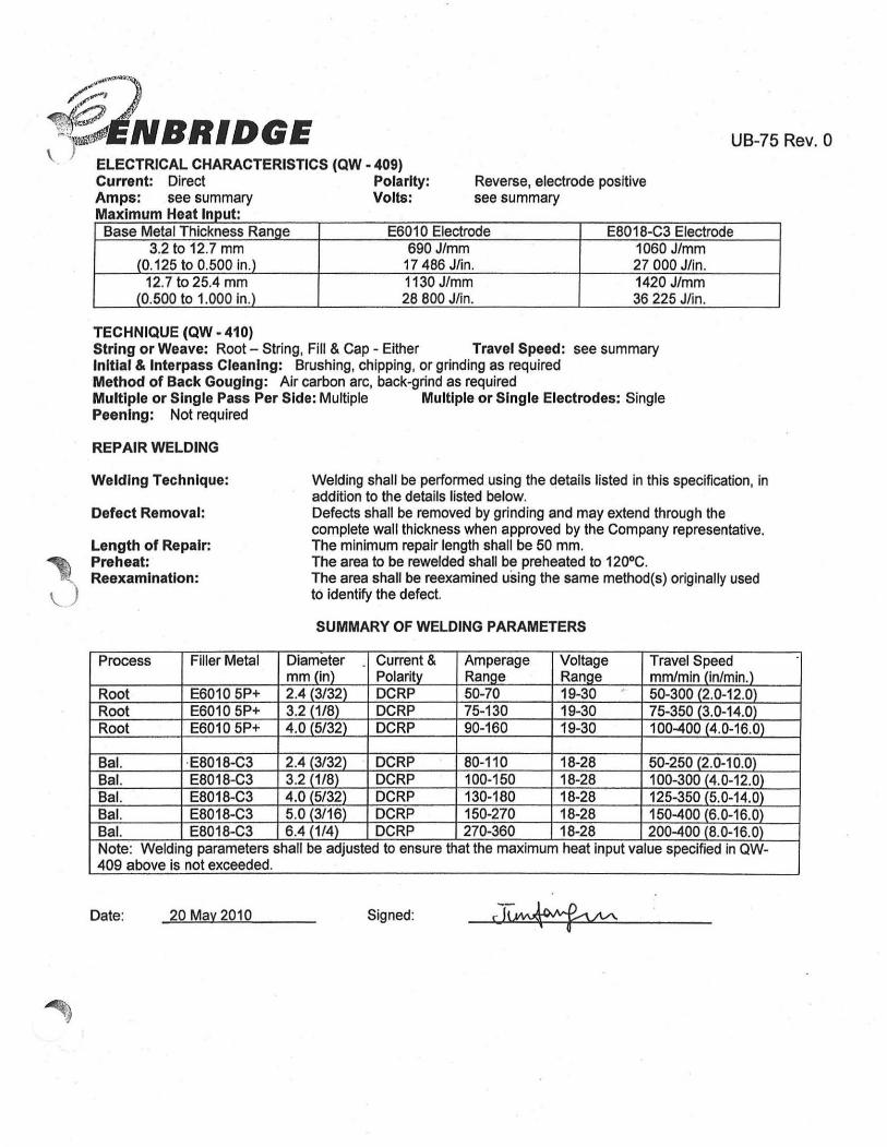
~:::-) ~INBRIDGE \ ) ELECTRICAL CHARACTERISTICS (QW - 409)
Current: Direct Polarity: Amps: see summary Volts: M i Hilt ax mum ea npu:
Reverse, electrode positive see summary
UB-75 Rev. 0
Base Metal Thickness Range E6010 Electrode E8018-C3 Electrode 3.2 to 12.7 mm 690 J/mm 1060 J/mm
(0.125 to 0.500 In.) 17486 J/in. 27000 J/in. 12.7 to 25.4 mm 1130 J/mm 1420 J/mm
(0.500 to 1.000 in.) 28800 J/in. 36225 J/in.
TECHNIQUE (QW - 410) String or Weave: Root - String, Fill & Cap - Either Travel Speed: see summary Initial & Interpass Cleaning: Brushing, chipping , or grinding as required Method of Back Gouging: Air carbon arc, back-grind as required Multiple or Single Pass Per Side: Multiple Multiple or Single Electrodes: Single Peening: Not required
REPAIR WELDING
Welding Technique:
Defect Removal:
Length of Repair: Preheat: Reexamination:
Date: 20 May 2010
Welding shall be performed using the details listed in this speCification, in addition to the details listed beiow. Defects shall be removed by grinding and may extend through the complete wall thickness when approved by the Company representative. The minimum repair length shall be 50 mm. The area to be rewelded shall be preheated to 120·C. The area shall be reexamined using the same method(s) originally used t6 identify the defect.
SUMMARY OF WELDING PARAMETERS
Signed:

~1 , \ }
" \ )
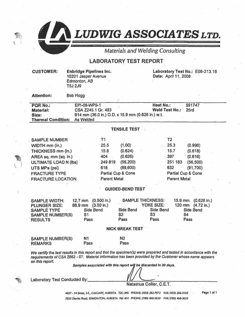
PROCEDURE QUALIFICATION TEST REPORT
PQR No. EPI-OB-WP9-1 Date March 19. 200B Welder (a) Brad Whitworth Welder (b) Shannon Whitworth Base Material CSA Z245.1 Grade -::--:--:--:-...::4~B:l::3 _____ _ Heat Number 591747 Carbon Equivalent ...;0;.;.~23~-:-::::-::7::":-:_ Size 914 mm (36.0 in.) 0.0. Wall Thickness 15.9 mm (0.625 in.) Preheat & Min. Interpass 120'C (250'F) Max. Interpass 160' C (320'F) . Technique Root & hot pass - string. Fill & Cap - weave Thermal Condition As welded Welding Progression Root & Hot: Down Remaining: Up Welding Position -;H:7o'-'ri:Uzo<"n~ta"7I-_ ::'"fix-e"7d"'T.(5::-:G""') Time Delay: NI A Test No.: _"..-;::::--:2"'5""R"'D=-.,--__ _ Electrode Trade Name: E6010 (Lincoln Fleetweld 5P+), EB010-P1 (Lincoln Pipeliner 8P+)
E8018-C3 (Air Liquide LA B01B-C3)
WELDING PARAMETERS
ELECTRODE CURRENT Pass Class Size Type & Amperage Voltage Arc Speed Heat Input
Polarity mm I min. (Lp.m.) kJ I mm (J I inch) 1a E6010 1/B DCRP 100 23.5 203 B.O 0.69 (17,625 1b E6010 11B DCRP 95 25.5 319 12.5 0.46 (11 62B 2a EB010-P1 5/32 DCRP 160 27.5 274 10.8 0.96 ' 24,444 2b EB010-P1 5/32 DCRP 160 29.5 290 11.4 0.9B 24,842 . 3a EB018-C3 3/32 DCRP 115 25.5 90 3.5 1.96. 50,271 3b E8018-C3 3/32 DCRP 95 24 66 2.6 2.07 52,615 4a E8018-C3 1/B DCRP 155 25 82 3.2 2.B4 72,656 4b E8018-C3 1/8 DCRP 125 25 39 1.5 4.81 ( 125,000 5a E8018-C3 1/8 DCRP 160 25 80 3.2 3.00 75,000 5b E8018-C3 1/8 DCRP 120 24 45 1.B 3.84 96000) '6a E8018-C3 1/8 . DCRP 155 23 89 (3.5) 2.40 61 ,114)
• Brad Completed the weld using six passes, Shannon used five.
-r 15J1mm
L--~~_---.l~ II
1.8 mm
Prepared by Ludwig Associates ltd. Page 4 of 4
\ I
~
Materials and Welding Consulting
LABORATORY TEST REPORT
CUSTOMER: Enbrldge Pipelines Inc. 10201 Jasper Avenue Edmonton, AB
Laboratory Test No.: E08-213.18 Date: April 11, 2008
T5J 2J9
Attention: Bob Hogg
PQR No.: EPI·08·WP9·1 Heat No.: 591747 Material: CSA Z245.1 Gr. 483 Weld Test No.: 25rd Size: 914 mm (36.0 In.) 0 .0. x 15.9 mm (0.626 in.) W.t. Thermal Condition: As Welded
TENSILE TEST
. SAMPLE NUMBER T1 T2
WIDTH mm (in.) 25.5 (1.00) 25.3 (0.996)
THICKNESS mm (in.) 15.8 (0.624) 15.7 (0.618)
AREA sq. mm (sq. In.) 404 (0.626) 397 . (0.616)
ULTIMATE LOAD N (Ibs) 249819 (56,200) 251 183 (56,500)
UTS MPa (psi) 618 (89,600) 632 (91,700)
FRACTURE TYPE Partial Cup & Cone Partial Cup & Cone
FRACTURE LOCATION Parent Metal Parent Metal
SAMPLE WIDTH: PLUNGER SIZE: SAMPLE TYPE SAMPLE NUMB.ER(S) RESULTS
SAMPLE NUMBER(S) REMARKS
GUIDED·BEND TEST
12.7 mm (0.500 In.) 88.9 mm (3.50 in.)
Side. Bend S1 Pass
SAMPLE THICKNESS:
Side Bend S2 Pass
YOKE SIZE: Side Bend S3 Pass
NICK BREAK TEST .
N1 Pass
N2 Pass
15.9 mm (0.626 In.) 120 mm (4.72 in.)
Side Bend 54
'Pass
We certify the test results in this report and that the specimen(s) were prepared and tested in accordance with the requirements of C.sA Z662 ·07. Materie/lnformatlon has been provided by the Customer whose name appears on this report.
Sample .... ,Ocl.t.d with thl. report wi b. dlscard.d In 30 d.ys.
Laboratory Test Conducted By: ______ ~.1.t..-:-.::::,':""'::::....-:-""""'---------Natashua Collier, C. E. T.
4027 · 14 SU" , S.E .• CALGARY, ALBERTA T2C 3K6 PHONE, (403) 262-7072 FAX, (403) 26&.3169
1925 Davits R~d. EDMONTON, ALBERTA T6£ 4N' PHONE: (780) .f68~JOJO FM:'(780) 468-3OJ1
Page' of f
~ \. )
, /) LUDWIG ASSOCIATES LTD.
CUSTOMER:
Attention:
PQR No.: Material: Size:
Materials and Welding Consulting
LABORATORY TEST REPORT
Enbrldge Pipelines Inc. 10201 Jasper Avenue Edmonton, AB
Laboratory Test No.: E08-213.16 Date: April 11, 2006
T5J 2J9 .
Bob Hogg
EPI-06-WP9-1 Heat No.: CSA Z245.1 Gr. 463 Weld Test No.: 914 mm (36.0 in.) 0.0. x 15.9 mm (0.626 in.) W.t.
591747 25rd
Thermal Condition: As Welded
NOTCH-TOUGHNESS TEST
TYPEO OF TEST: Charpy V-Notch -5°C (23°F)
ORIENTATION: Transverse TEST TEMPERATURE: SPECIMEN SIZE: 10 x 10 mm .
Specimen Number
Notch Location
J2.1 · Weld Metal within 1/16" of root J2.2 Weld Metal within 1/16" of root J2.3 Weld Metal within 1/16" of root
J3.1 HAl J3.2 HAl J3.3 HAl
Impact Values Joules (ft.lbs)
152 (112) 130 (96.2)
>163 (>120)
>163 (>120) >163 (>120) >163 (>120)
We certify the test results in this report and that the speclmen(s) were prepared and tested In accordance with the requirements o( ASME Section VIII, Div. I, UG-B4 - 2007 edition and latest addenda. Material Information has been provided by the Customer whose name appears on this re art.
Sample. I •• ocl.ted with thl. report be dIscarded In 30 dlYS.
Laboratory Test Conducted By: . . ~ • Natashua Collier, C.E. T.
4027. 14S1t .. ~ S.E., CAlQlRY, Al8ERTA T2G 3K6 PHONE, (403) 262·7072 FAX, (403) 266-3169
7925 D.vles Ro.d, EDMONTON, ALBERTA 16E 4NI PHONE, (780) 46(1.3030 FAX, (780) 468·3032
Page 1 01 1

~) " ).
CUSTOMER:
Attention:
PQR No.: Material: Size:
Materials and Welding Consulting
LABORATORY TEST REPORT
Enbrldge Pipelines Inc. 10201 Jasper Avenue Edmonlon. AB
Laboratory Test No.: EOa·213.18 Date: April 11. 2008
T5J 2J9
Bob Hogg
EPI-08-WP9-1 Heat No.: CSA Z245.1 Gr. 483 Weld Test No.: 914 mm (36.0 in.) 0 .0. x 15.9mm (0.626 In.) w.t.
591747 25rd
Thermal Condition: As Welded
HARDr-lESS TEST
Type ofT est: Vickers 10kg (HV 1 0) Instrument: Leco V-100-C1
'm - ...----.---<' ,t§ = 1· " " ,. . ." ."
\ ,. . .. I I .. --- \
...
We CfJrtify the test results in this report and that the speGlmen(s) were prepared and tested In OGGoroonoe with the requIrements o( ASTM E92·82 (Reapproved 2003). Meterial inform. Yon h.s been provIded by the Customer whose name app •• rn on this report.
Semples es.socleled with this repay"/! dlSCerd~d In 30 deys
Laboratory Test Conducted By: ______ I-IlLJL//,--, l~-~_",___::_==_------_ • Natashua Collier. C.E.T.
4027 - "51,.., S.E., OUG.'IRY, ~LBERTA T2G JK6 PHONE: (40J) 261·7072 FAX, (4OJ) 266·J .69
7915 Oavles Road, EDMONTON, ALBERTA T6[ 4Nr PHONE: (780) 468·3030 FItX: (780) 46&-3032
Pagel of 1

~~ " ~
--- ':1;;/ '.
~I~q - MILL I"t:RTIFICATE Certificate l PackaaelD: 4454 Chemistry Celtific.ate
Fonn Number: L 2422 ·
Customer: ENBRJDGE PIPEUNES tHe. Customer Ortler Oate: Size: 3 6.000 In No: P~722 O3J!>4I2D01
Speclfieatlon: API5L 43RO EO I ENBfUOGE &S103-2006 REV 0 8tU06 MIROrder TIme: Wall: D.625 In
No: 7000888'1 13:05:41 Gf'ad&: X70 PSL 2
Coli PIpe Typo C Mn S P SI I Cu I NI I C, V I Cb I Sn I Mo I AJ C. B 1 TI I N I c. CEFcm So AI
He.t 511747
HEAT ..., .... ..... .."" .... .... CUI o. .. O.tol o.---;-~ 1.0471 0 .110 o.on .. -...... i ' .01 ..... ..... o. .. ;;:;; C!2 .170 PRODUCT • .113 ... , ... ..... .~ . G.2: • .lO 0.07' . .... 0.07'~ a.cUl O.1U 0 . .,7 .. "" o.oocnJ 0,01' . .... ..... o." 0 .n1
C53 0173 PRODUCT .... 1." ... , ..... 0.> .... . ... .., ..0>3 •.• nl • · ... 1
0.1tS 0.031 .. "" o.ooo~ . U ti O.tel ..... .. " •. "
Deoxidization Pradice: Numilum Fully KiRed WE HEREBY CERTIFY THATTHE PRODUCT rUmace: E1.ECTRIC ARC Casting: CONTINUOUS SLAB Rofmg Mil: STECKEL OESCRIBED ABOVE HAS PASSED AU THE (l,l!.
TESTS REQUIRED BY THE SPECIFICAT IONS. J!..-.C .>.' I O: ::!I.l C!;a:1ti t Ouattr Assurance
' .

\.
rHUn-UJ npel1nes t;anada
RIll a....,_ .... 1431-70_ EdrMMon, _ TIP INa
+780-955-3518 T-724 P003/003 F-543
Date mldIy; ?!l®- i? II - tJ Y Time; ______ _
N ; (7101--(780)_ ~~g:; ·~252r-
RADIOGRAPHIC TESTING REPORT ClleatlC"'Iracf4r:~ I!.;..~J.~.~ '.j~.,fL.. ~ '_-..-_--:_
Project: ~. -I; ~:. ~ I'M Loeatlo.: 11.·:1. A'!3 f ..{;?nJ)
(]Ieat Job 'rr.o.',
RTDJob': tJt};;~/ .
RTD Procedmre: ;( 1- lJ f!) I Rev. ':
CedelSpecUlcadoD: "'. .<.13-2 he. ,2 . . rxz Item(I)I •• pected: .36 " '1':::.~ I~JJa
Materl_1t Type; /!"" '~ s;.-rl. / Weld Reinforcement: .,,3'-W,6.!.dl ...... '--_
Esr-re: B"s'ingJe Wan 0 Double Will Vl ...... g: ci?single Wan 0 Double Wan RTD T"hnique;~A~;;:r:..,.l . ' ~;; "'DH: '. , ..... _"" '. ' '': . ~<··'<'i:.
D - ~ 17" \I 7",,,, I / - 17,,// -"' .. '" ' ~.:.
.
Type: g Iridium 192 nube Source Size: 0.005" g Front g Back o Cobalt 60 . Other Focal Spot Size: ---- 0.010" U Pront U Back
. 'SOD: ____ PI"!'C ... ID,: [3'",o"u,", 0 Automatic Scr ... Type: Ib . Pi/Z_;.... OFD: Note:: 1M OPlJ (Ob}tel 10 FII". Dt/lance) .1111/1 U wUtJlllrulJrom 1M maxi",,,,,. df,tanct/ro", lire 101If"c;C ,Ide o/thct1bJeel io t/Nfl/Iff.
,'. . . . ' .
\ L '; ' , .. ' -
'j J.III . .
.
L ~R"'3I.t>, I /{".f. ;H'~" ·1tJ7A - ~ In/!
I •
" •• o· . l ' , ,. )T.
. , • ::/.
I (')I :., I '
~/('.r (')S', _TIm<: 070() I!odTirne: I?OO T'M, SI"", .... , ~ ~ .IJ ,f)f}..
Total Houn:
' .
l&Jc Knoooeuw.
El coso 0 ASNr 0 SlIT V Lev": ff -f Dis<.: f{ 1 ~: ..... , .... tN.me: lJ!h--.GItIAA,f.o ecrt':
~~ I~, __ ~D*~: ____________ ~~~~~~~ __ ~O~CG_S_D~O~AS>rr ___ O~S>rr __ ~O~L~.v_e\_I~O~~~O~C~EOO~-~~~~~~;~~' ColllWOlblea: Dr" ONo
TOOlll ... OJ .R.clUltS are &II lD~OD oCtbc iD.spoction method, aot a JUUUl'tt. Clicol dltD&ture iDdlcatet IcccptaQCCI of report, Rsults &I)d applic.able charles. Oct.2q.~ Whitc :- Oiall Orta-OieDt Yellow-OfIic:e Pink-loYOice OokleD ,Rod·TccMiciao

,
Address:
POfWO:
RTD QUALITY SBRV1~ INC. 1431-70 AVENUE, EDMONTON, ALBERTA, CANADA T6P INS TIL: (780) 440-6600 FAX: (7~O) 440·2538
+780-955-3518 T-724 P002/003 F-643
NDEREpORT # 2585 DlIe m/dly: 2)".. _ <It-P sr' Page ---L- of ---L
RTDlobN: 009'11 RTD Dep. #: P.s lob location: L<::-"'«V='-''L-l~-::; ______ _
Procodwe(s): _?n-=-=--,-,T,--c-il2",' '-'0<:....>5<.. .... _____ _
Code(s): -'C""S""'Au-· ... :z"-""~-"6'-'.:?.......... .....0'-'1'--__ _ Client Rep.:
Part (s) Examined: ",3~6,,--< .J.1'. ... 4f1ljz:L,-'t.J~(.;..I{:...'jLd.(~ ..... • t;:r.&>"'<>1t!."tt.J~<9!t''-' tIdL",,' r-".yrpf~=L-..Jf.~!::!>.~ _______ _ Calibration Standard: ; I
Surface Condition: -~-:w""·~el-dm-'-.-I -O-Qrou-n-d--O-Ma-ch-in-'-d-O-s-an-d-blo-,,-.-d-O-h-i-.I-ed-O-O-th-,,----------
Method: ~ OPT ovr DOthe, Surface Temp (CO): 0<5 >S~60 0>60
Equipment
~ l!!rYoke D Penn. Mean" DCoil o BI.oIe';",.
alDA"elN
/07.2.2 CalibratiOD D.te
?n",-IJ/- ,,1'
Test Medium
o Wet Fluorescent
Technique
~C Doc
!..PI o Water Washable D Post Emulsified D Solvent Removable
o Alloy Aoalyzer
. 0 Hard .... Too'"
DOlfI"
~poWd.r
Black and Whit. Fluor .. cent Visible Dye
DOlhcr . B Continuous
Ro.idual o Other Dwell Time: Developer Time: ----
. :., . .... ' ~ ..... .. ,' .~: . , ,::. "
. ..... ' .: ,:: .. i.',:':: ... :.,. .
A .. ; ..... : DO&! 6&I,Av1J( f)
. . ,j, .•. ;
o COSB 0 ASNT CI SIfT 1Ave1: 0 , Diooip'''e: Dur C1MT OPT CI ET ORT OVT
Unll: Km: T,.vol l1mo;
011
... .... . . ,
-- ---Stari Time: Stop Time: Work bn:
--~ ------o OTM .. I CI S.bow.. .... qulted TaIa'lva: ___ _
• •• •• •• • • : •• :.:· •• l ..... : . ........ ; .. : •••••• . •• 1 ..,
Tullal, I .. : ~'§t~~"u"""'~JM.U<~_=~=..-COS 0 ASNT 0 SNT L ... ' : 0 I
Our em OPT CIIIT ·(3"RT Ovi ?30,
Ob.clptiae:
Slplhm;
Clialt Name: M Coa.umabla: Climt Sla'natare:
1'094, Rev. 2 ·Rnuh. ate 1.0 lntuprcttUOIl oribe IDlpcctiOIiIMthod. not • JUlrante., Client ","'~ Jlldlc.lct accepl&Gc:O of report. rauki end applicable char,Cl. Apr. U. 0) Wtt - CHenl Yellaw - OftIce Pink -invoice Ooldca R.od -TecbaicJan
PROCEDURE QUALIFICATION RECORD (PQR)
Procedure Qualification No:
Welding Procedure Specification No:
UB-70-1
UB-70
JOINTS
t ~3j) <) 0.2"" ,\2/) ! ! ( 1 "')
118' I-!
BASE METALS Material Spec: _____ :::;SA~5::.1:::.6-----
Type or Grade: __ .,-__ ..:6::.0'-/7"'0'--_-:-::-:-_ P No: _--,1,--_ Group No.: _",,1:.;&:;.2,--_
Heat Number: ___________ _
ASME Carbon Equivalent: _____ ---'0,;,..4'--____ _
CSA Carbon £quivalent: ___________ _
f
To: To: To: To: To: To:
? 118"
SA 537 CL 2
P No: 1 Group No. : _-,3,--_
0.45
Coupon Thickness: Machined to 0.249" To Machined to 0.249" Coupon Diameter: __ --'PI:::.at::e'--_______ -'Tc:o ______ ---'P.:;la:..:te:::.... _____ _
FILLER METALS Process
Number of Layers SFA Spec. No.
AWS Class No. F·No. A·No.
Size of Filler Metal Manufacturer
Trade Name Heat/Lot No.
:
:
:
:
:
:
:
:
:
:
:
:
Weld Metal Thickness
Flux Type Flux Trade Name
Other :
:
POSITIONS
SMAW 1
5.1 E60105P+
F3 A1
1/8" Lincoln .
Fleetweld 5P+
0.100" NA NA
Covered Electrode
SMAW 2
5.5 E8018-C3
., F4
A10 3/32"
Air Liquide LA8018-C3
0.149" NA NA
Covered Electrode
Position of Groove: 3G 3G Process: I SMAW SMAW
Welding prOgreSsion:~L -==_ -==_ -=~_U~_P~_h=_il=_1 =_ -==_ -==_l-~=_ -==_-==_-==_ -==_ -::=U~_P~_h=_il=_1 =_ -==_ -==_ -==_ -==_l-~=_ -==_ -==_ -==_ -==_ -==_ -==_ -==_ -==_ -==_ -==_ -=j..,J
1 of 3
a NBRIDGE PROCEDURE QUALIFICATION RECORD (PQR)
PREHEAT Preheat Temp: 50' F
--------------------~~~--------------------Interpass Temp: __________ ------.::5::.50::.·..,;F,.-----:---:----------
Other: ________ T_e_m--'-p_e_ra_t_u_re_m_o;..n_i.;..to;..r...;e..;.d_u'-s;..in-'g"-'.te;;..m---"p_le:..;s;..t",ic.;..k,,-s _______ _
POST WELD HEAT TREATMENT Temperature: _______________ --:.;Nc..A=----______________ _
Time: ----------------------------------------------Heating: -------------------------------------------------------Coollng: _______________________________ __
GAS SFA Composition Flow Rate (CFH)
Shlelding:lt-___ -:-N:::A;..... __ -t-_______ -t-_______ -+ ___ -+ ___ --l Backlng:L.. ___ ..:.N::.A=----__ --L.. _______ --L.. _______ -l. ___ -l. ___ --l
ELECTRICAL CHARACTERISTICS :
:
:
:
: t :
:
Process Current Type
Polarity
Amps
Volts Maximum Heat rnpu
(Joules/Inch) Tungsten Electrode
Size & Type Mode of Meta I
:
:
Transfer for GMAW Electrode Wire
Feed Speed
Electrode Stick OUI :
TECHNIQUE
:
5
String or Weave Bead
Multiple or Single Pas (Per Side
Multiple or Singl Electrodes
):
e
Gas Cup Size
Oscillation
Other
:
:
:
:
SMAW- F3
Direct (DC)
Reverse (EP)
82-87
22-26
17,486
NA
NA
NA
NA
Process Filler Metal
SMAW E6010 5P+
SMAW ES018-C3
SMAW ES01S-C3
F3 String
single
NA
NA
NA
SMAW -F4
Direct (DC)
Reverse (EP)
72-92
18-22
27,000
.'
Diameter Amps Volts Travel (IPM)
l/S" S5 24 7
3/32" 90 20 4
3/32" SO 21 4
F4
String & Weave
Multiple Passes from One Side
single
2 of 3
,
PROCEDURE QUALIFICATION RECORD (PQRj
TENSILE TEST
Specimen No.
GUIDED BEND TEST Specimen No.
TOUGHNESS TEST Specimen
No.
1
2
3
4 5
6 7 8 9
OTHER TESTS Hardness:
Width Thickness
(In.) (In.)
Type
~.
Notch location
SA 516 HAZ
SA516 HAZ
SA516 HAZ
Weld Zone
Weld Zone
Weld Zone
SA-537 HAZ
SA-537 HAZ
SA-537 HAZ
Area Ultimate Total Ultimate Unit Type of Failure
(In') Load {lb.1 Stress (psi) & location
Figure No. Result
Notch Impact literal Qu.,fflalUon
Values % Shear Expansion Type Temper.hlle
ft-Ibs (Inches)
V-notch -50"F 34 NA
V-notch -50"F 35
V-notch -50"F 38
V-notch -50"F 26
V-notch -50"F 25
V-notch -50"F 26
V-notch -50"F 58 -V-notch -50"F 45
V-notch -50"F 61
----------------------------------------------Ferrlte: ______________ ,-_________ -, ________ __
Chemical Analysls: _________________________________ __
liquid Penetrant: _________________________________ __
PMI:
Welder's Name: Greg McKecheran File No.:____ 10 NO.:-:-:-....,...,~_
Test Conducted By: ___ .;..A"'lf.:.o_r M=e.:;ta:...li.:.u,-,rg"ic:.:a;;..I.:.Co.:.m=p.:.an-"Y,-l:.:t.:.d.___ lab. Test No.: 09-363
We certify that the statements In this record are correct and that the test welds were prepared, welded, and
tested In accordance with the requirements of Section IX of the ASME Code.
Manufacturer: _______ E:;n.:.:b::.r::id"'g;:.e.:.P;.tip:.:;e.:.;lin:.:;e:;s:.;l:.:.td::;. ______ _
Oate: ________ ~5.:.-J:;u::.I-.:.O.:.9 ________ _
Signed: __________________ _
3 of 3
?) . ~NBRIDGE
PROCEDURE QUALIFICATION RECORD (PQR)
Procedure Qualification No:
Welding Procedure Specification No:
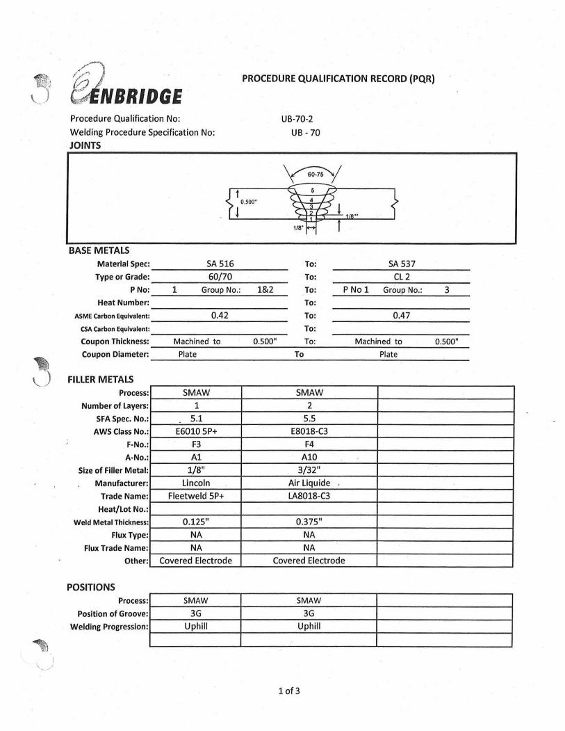
UB-70-2
UB -70
JOINTS
'y?/
BASE METALS
Material Spec: ____ --'':-:-~:.....---_ Type or Grade:
--------~~---------
SA 516 To:
60/70 To:
PNo: _~--,_~~~~--,~~ 1 Group No.: 1&2 To:
Heat Number: To: ------~~-------
ASME Carbon Equivalent: --------~~--------
0.42 To: CSA Carbon Equlvalent : ___________ __ To:
SA 537
CL 2
P No 1 Group No.:
0.47
3
Coupon Thickness: __ ===:...:::..... __ == __ --=.::.:.. ___ ====-.:.:..... __ -,0;;;.5;.::0.:,0_" _ Machined to 0.500" To: Machined to Coupon Diameter: __ -'-.:...:.;'-___ _____ -'-______ -'-'-= _____ _ Plate To Plate
FILLER METALS Process
Number of Layers
SFA Spec. No.
AWS Class No.
F-No.
A-No.
Size of Filler Metal
Manufacturer
Trade Name
Heat/Lot No.
Weld Metal Thickness
Flux Type
Flux Trade Name
Other
POSITIONS
:
:
:
:
:
:
:
:
:
:
:
:
:
:
SMAW
1
5.1
E6010 5P+
F3
A1
1/8"
Lincoln
Fleetweld 5P+
0.125"
NA
NA
Covered Electrode
SMAW
2
5.5 E8018-C3
F4
A10
3/32"
Air Liquide
LA8018-C3
0.375"
NA
NA
Covered Electrode
process:1 SMAW SMAW Position of Groove:I-___ -'3:.:G:,.,.,... __ -+ ____ --:--'3:.:G:,.,.,... ____ -+ ___________ ~
Welding progresslon:I-__ --'U"'p;.:,h:;,;iI;",1 __ -+ ____ --'U"'p;.:,h:;,;il;",1 ____ -+ ___________ ~ ~--------~----------------~--------------~
10f3
filNBRI~GE PROCEDURE QUALIFICATION RECORD (PQR)
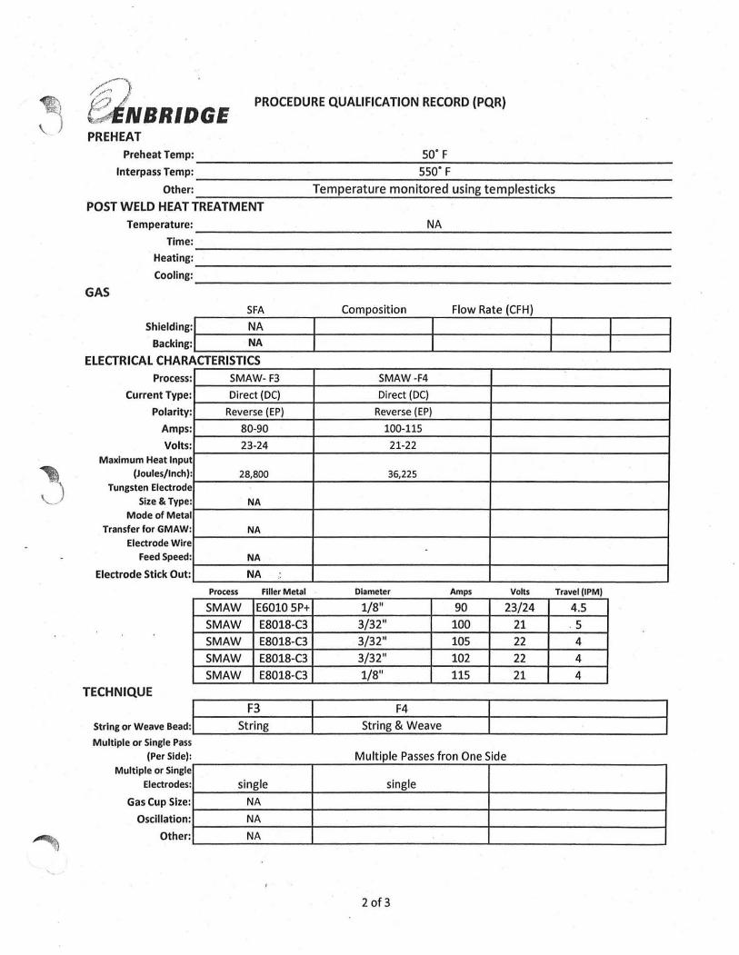
PREHEAT
preheatTemp: ______________________________ ~5~0=·~F~-----------------------------Interpass Temp: 550' F
Other: ----------------T=e-m--p-e-ra~t-u-re--m-o-n~i::'to.;;.r.;;.e-d~u-s""7in-g~te-m--p7Ie-s7t:-ic7k-s ---------------
POST WELD HEAT TREATMENT Temperature: ______________________________ ....;..N"-A'-____________________________ _
Time: -------------------------------------------------------Heating: ______________________________________________________________ __
Cooling: ______________________________________________________________ __
GAS SFA
Shlelding:1 NA Backing: . NA
ELECTRICAL CHARACTERISTICS :
:
:
:
: I
Process CurrentType
Polarity
Amps
Volts Maximum Heat Inpu
(Joules/Inch Tungsten Electrod
Size & Type Mode of Meta
Transfer for GMAW Electrode Wir
Feed 5peed
): e : I : e :
Electrode Stick Out :
TECHNIQUE
SMAW- F3
Direct (DC)
Reverse (EP)
80-90
23-24
28,800
NA
NA
NA
NA
Process Filler Metal
SMAW E6010 5P+
SMAW E8018-C3
SMAW E8018-C3
SMAW E8018-C3
SMAW E8018-C3
Composition Flow Rate (CFH)
SMAW -F4
Direct (DC)
Reverse (EP)
100-115
21-22
36,225
Diameter Amps Volts TravelllPM)
1/8" 90 23/24 4.5
3/32" 100 21 5
3/32" 105 22 4
3/32" 102 22 4
1/8" 115 21 4
SIring or Weave Bead : I-I-----:s...:t~..:~n:...g------t-------::-St-r:-in-g-;~:-4:...w..,.e-a-v-e------t_-----------------------1 Multiple or Single Pass
(Per Side): e Multiple or Singl
Electrodes
Gas Cup Size
Oscillation
Other
:
:
:
:
Multiple Passes fron One Side
single single
NA
NA
NA
2 of 3
/;;:;7 t;ENBRIDGE
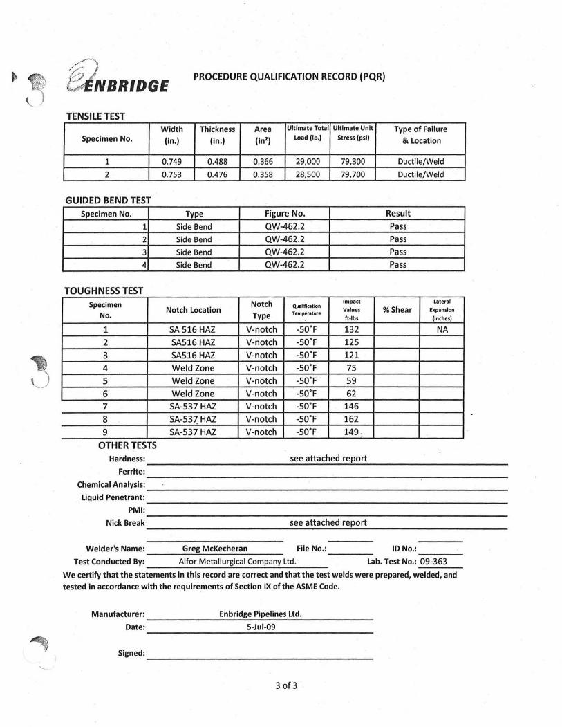
PROCEDURE QUALIFICATION RECORD (PQR)
TENSILE TEST Width Thickness Area Ultimate Total Ultimate Unit Type of Failure
Specimen No. (In.) (In.) (In') Load (lb.1 Stress (psi) & location
1 0.749 0.488 0.366 29,000 79,300 Ductile/Weld
2 0.753 0.476 0.358 28,500 79,700 Ductile/Weld
GUIDED BEND TEST Specimen No. Type Figure No. Result
1 Side Bend QW-462.2 Pass
2 Side Bend QW-462.2 Pass
3 Side Bend QW-462.2 Pass
4 Side Bend QW-462.2 Pa ss
TOUGHNESS TEST Specimen Notch Impact Lateral
Notch location Qllitltflcil ion
Values % Shear hpansion No. Type Trmper.turr
ft·lbs (Inches)
1 . SA 516 HAZ V-notch -50"F 132 NA
2 SA516 HAZ V-notch -50"F 125
3 SA516 HAZ V-notch -50"F 121
4 Weld Zone V-notch -50"F 75
5 Weld Zone V-notch -50"F 59
6 Weld Zone V-notch -50"F 62
7 SA-537 HAZ V-notch -50"F 146
8 SA-53? HAZ V-notch -50"F 162
9 SA-537 HAZ V-notch -50"F 149 ·
OTHER TESTS Hardness: ____________ ---'s;::e.:.e..:a"'tt:.:a.:.ch"'e:.:d;...r:..::e"'p..::o.:.;rt=--___________ _
Ferrite: ----------------------------------~----------Chemical Analysls: _______________________________ _
Liquid Penetrant: _______________________________ __
PMI: _________________________ ~~~~--~----------------------Nick Break see attached report
----------~~~~~~~------------
Welder's Name: Greg McKecheran File No.:_____ 10 NO.:-:-:--:-~_
Test Conducted By: ___ A..;;I;..;fo"-r..;.M.:.;e:..;ta",I",lu",rg,,,ic;;.:a.;.1 ",Co",m=pa",n"-y..:U,,,d..;;' -:-__ lab. Test No.: 09-363
We certify that the statements In this record are correct and that the test welds were prepared, welded, and tested In accordance with the requirements of Section IX of the ASME Code.
Manufacturer: ______ ....:::En~b:.:.r:.:ld:2g.:.e .:...P",ip::;e:::lin~e:::s::;lt::d::... _____ _ Date: ________ ---'5:.-.:,:)u:..;I-..:O.:.9 ________ _
Signed: ___________________________________ __
30f3


