Embed Size (px)
Citation preview
Final Report: Enbridge Line 5 - East Straits
of Mackinac Hydrostatic Test
Prepared for:
Enbridge Energy, Limited Partnership
AFE: 20007132
Hydrostatic Test #: 5-17-153
REDACTED SUBMITTAL -- PUBLIC COPY
Excellence & Integrity
Enbridge Line 5 - East Straits of Mackinac Hydrostatic Test Page | 1
TABLE OF CONTENTS 1 EXECUTIVE SUMMARY............................................................................................................................................... 4
2 TEST SPECIFICS .......................................................................................................................................................... 4
2.1 TEST SECTION DESCRIPTION ........................................................................................................................4
2.2 TEST MEDIUM ..........................................................................................................................................4
2.3 TEST PRESSURE RANGES .............................................................................................................................4
2.4 ELEVATION PROFILE ...................................................................................................................................5
2.5 EQUIPMENT SETUP ....................................................................................................................................6
3 TEST OVERVIEW ........................................................................................................................................................ 6
3.1 SUMMARY OF TEST ....................................................................................................................................6
3.2 PRESSURIZATION AND PV PLOT ....................................................................................................................7
3.3 STRENGTH TEST ........................................................................................................................................8
3.4 LEAK TEST ...............................................................................................................................................8
3.5 WEATHER CONDITIONS ..............................................................................................................................8
3.6 TEMPERATURE SUMMARY ...........................................................................................................................8
4 TEST ACCEPTANCE ..................................................................................................................................................... 9
4.1 STRENGTH TEST ........................................................................................................................................9
4.2 LEAK TEST ...............................................................................................................................................9
4.3 TEST CRITERIA CONFIRMATION................................................................................................................... 10
APPENDIX 1 – TEST RECORDS ............................................................................................................................................ I
1 PRESSURE TEST PLAN – NORTH STRAITS SITE ............................................................................................................. I
2 PRESSURE TEST PLAN – MACKINAW STATION SITE ..................................................................................................... I
3 701 PRESSURE TEST REPORT ....................................................................................................................................... I
4 702 PRESSURE TEST DATA SHEET ................................................................................................................................ I
5 PV PLOT ...................................................................................................................................................................... I
6 CHARTS ...................................................................................................................................................................... I
7 TEMPERATURE PROBE GRAPHS .................................................................................................................................. I
8 704 PRESSURE TEST CHECKLIST................................................................................................................................... I
9 705 PRESSURE TEST REQUIREMENTS CHECKLIST ........................................................................................................ I
APPENDIX 2 – TEST EQUIPMENT & OQ’S .......................................................................................................................... II
1 TEST SCHEMATIC ....................................................................................................................................................... II
2 PHOTO REPORT ......................................................................................................................................................... II
REDACTED SUBMITTAL -- PUBLIC COPY
Excellence & Integrity
Enbridge Line 5 - East Straits of Mackinac Hydrostatic Test Page | 2
3 EQUIPMENT CERTS .................................................................................................................................................... II
4 HYDROTEST OPERATOR QUALIFICATIONS ................................................................................................................. II
APPENDIX 3 – PROJECT SPECIFIC HYDROTEST PLANS....................................................................................................... III
1 PROJECT HYDROTEST PLAN ...................................................................................................................................... III
2 HYDROTEST PLAN SUBMITTED TO EPA ..................................................................................................................... III
3 TEMPERATURE VS. PRESSURE CORRELATION ........................................................................................................... III
APPENDIX 4 – TEST MEDIUM ........................................................................................................................................... IV
1 WATER ACQUISITION ............................................................................................................................................... IV
2 LINE FILL ................................................................................................................................................................... IV
3 STABILIZATION ......................................................................................................................................................... IV
4 DEWATER AND TREATMENT ..................................................................................................................................... IV
5 PHOTO REPORT ........................................................................................................................................................ IV
APPENDIX 5 –SYSTEM ISOLATION AND VALVE POSITIONS ............................................................................................... V
1 SYSTEM ISOLATION ................................................................................................................................................... V
2 VALVE POSITIONS ...................................................................................................................................................... V
APPENDIX 6 –TEMPERATURE SUMMARY ........................................................................................................................ VI
1 TEMPERATURE DATA SUMMARY TABLES ................................................................................................................. VI
1.1 STRENGTH TEST ....................................................................................................................................... VI
1.2 LEAK TEST .............................................................................................................................................. VI
APPENDIX 7 – MICHIGAN TECHNOLOGICAL UNIVERSITY WATER TEMPERATURE MEASUREMENTS ............................... VII
1 WATER TEMPERATURE OVERVIEW .......................................................................................................................... VII
2 DATA SUMMARY TABLE .......................................................................................................................................... VII
REDACTED SUBMITTAL -- PUBLIC COPY
Excellence & Integrity
Enbridge Line 5 - East Straits of Mackinac Hydrostatic Test Page | 3
SIGNATURE PAGE
WRITTEN BY:
MEGAN HALVER
AUGUST 28, 2017
INTEGRITY ENGINEER
DULUTH, MN
LAKE SUPERIOR CONSULTING, LLC
SIGNATURE DATE
APPROVED BY:
GARY ZUNKEL, PE
AUGUST 28, 2017
SENIOR DIRECTOR OF INTEGRITY
MANAGEMENT
DULUTH, MN
LAKE SUPERIOR CONSULTING, LLC
SIGNATURE DATE
KORY JOHNSON, PE
AUGUST 28, 2017
PIPELINE ENGINEER
DULUTH, MN
LAKE SUPERIOR CONSULTING, LLC
SIGNATURE DATE
REDACTED SUBMITTAL -- PUBLIC COPY
Excellence & Integrity
Enbridge Line 5 - East Straits of Mackinac Hydrostatic Test Page | 4
1 EXECUTIVE SUMMARY
The purpose of this report is to summarize and document the results from Test # 5-17-153, the East segment of
the Line 5 Straits of Mackinac Hydrostatic Pressure Test for Enbridge US Special Projects. The test was conducted
by Milbar who was subcontracted through UPI, the general contractor. Site Engineers Megan Halver and Kory
Johnson observed the test. Gary Zunkel monitored the test remotely. The Line 5 Straits of Mackinac Hydrostatic
Pressure Test fulfills Enbridge’s requirements per Paragraph 25.f and 71.b of the Consent Decree for U.S. vs.
Enbridge Energy, Limited Partnership, et. Al., (Civil Action No: 1:16-cv-914).
An 8-hour continuous pressure test was conducted. The Strength Test was completed with pressure held above
1200 psi at all locations on the pipe segment for a duration greater than 4.25 hours. The leak test was completed
with the pressure held above 660 psi at all locations on the pipe segment for a duration greater than 4.25 hours.
2 TEST SPECIFICS
2.1 TEST SECTION DESCRIPTION
This hydrostatic test was comprised of the following elements:
• Test #: 5-17-153
• Test Segment: East Segment of Line 5 across the Straits of Mackinac
o Trap 1475.68-5.1-ST-2 (STA 19936+01) to Trap 1479.55-5.1-ST-1 (STA 20141+22)
o Note: Stationing and Milepost Values are from trap to trap based on 2016 Geopig Data
• Length: 4.09 Miles
• Test Site Location: North Straits Pipe Yard @ MP 1475.68, STA 19936+01
• Mainline Pipe Summary: 20” OD x 0.812” WT x Grade A seamless pipe
o Note: Additional Facility piping, valves, flanges, and fittings were also tested.
A full list of all materials has been included in the Pressure Test Plans in Appendix 1.
2.2 TEST MEDIUM
Line 5 East Straits Test # 5-17-153 was tested with water on 6/16/2017. Additional details on fill,
stabilization, dewatering, and water quality are outlined in Appendix 4.
2.3 TEST PRESSURE RANGES
All components were tested to 1200 psi (minimum) for 4.25 hours, followed by 660 psi (minimum) for
4.25 hours. Hydrostatic test pressures were established based on the following elevation profiles and
are outlined in the Project Hydrotest Plan, located in Appendix 3.
REDACTED SUBMITTAL -- PUBLIC COPY
Excellence & Integrity
Enbridge Line 5 - East Straits of Mackinac Hydrostatic Test Page | 5
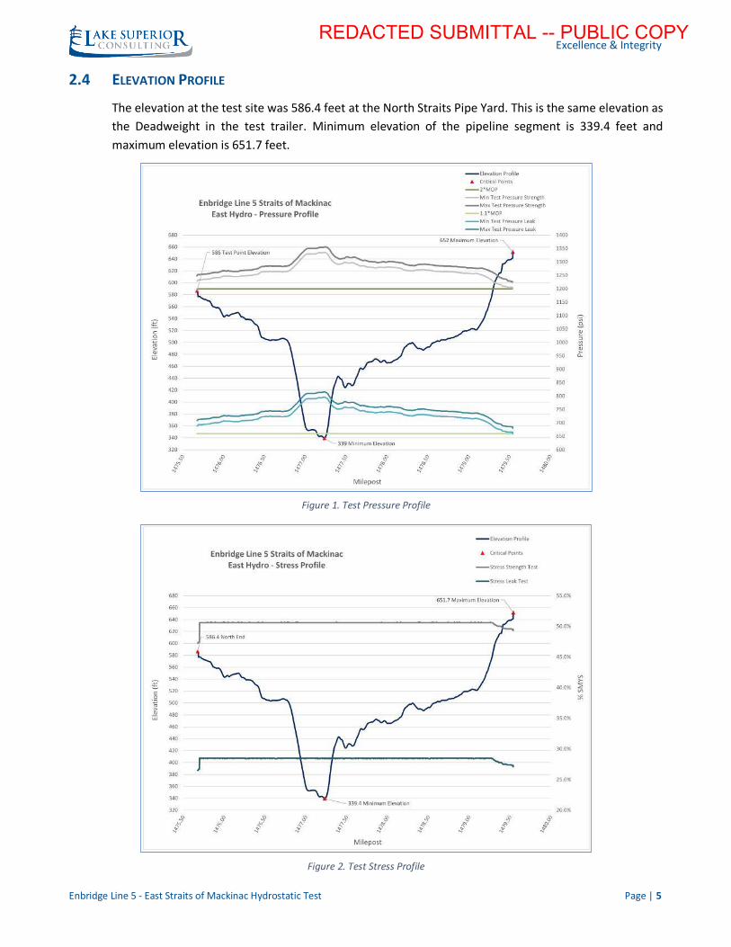
2.4 ELEVATION PROFILE
The elevation at the test site was 586.4 feet at the North Straits Pipe Yard. This is the same elevation as
the Deadweight in the test trailer. Minimum elevation of the pipeline segment is 339.4 feet and
maximum elevation is 651.7 feet.
Figure 1. Test Pressure Profile
Figure 2. Test Stress Profile
REDACTED SUBMITTAL -- PUBLIC COPY
Excellence & Integrity
Enbridge Line 5 - East Straits of Mackinac Hydrostatic Test Page | 6
2.5 EQUIPMENT SETUP
Milbar conducted the test using Test Trailer 25. The equipment set-up by Milbar included:
• North Straits Pipe Yard, Test Site (Milepost 1475.68)
o 1 Deadweights, for strength test (S/N: 26747)
o 1 Deadweights, for leak test (S/N: 883)
o 1 Pressure Gauge (S/N: 218170D0023)
o 1 Pressure Recorder (S/N: 102111-2)
o 1 Back-up Pressure Recorder (S/N: 1215152)
o 1 Pressure & Temperature Recorder (Ambient, Pipe, and Ground) (S/N: 1000225)
o 1 Above Grade Pipe Temperature Recorder (S/N: 14342077)
o 1 Back-up Above Grade Pipe Temperature Chart (S/N: 0807137)
• Northeast Temp Probe (Milepost 1475.74) (
o 1 Pipe & Ground Temperature Recorder (S/N: 14342071)
• Southeast Temp Probe (Milepost 1479.38)
o 1 Pipe & Ground Temperature Recorder (S/N: 15015179)
• South Mackinaw Station, End Site (Milepost 1479.54)
o 1 Back-up Pressure Recorder (S/N: 202E-52081)
o 1 Pressure Gauge (S/N: 218170D0020)
o 1 Above Grade Pipe Temperature Recorder (S/N: 06215056)
Details and photos of all equipment locations and certifications are outlined in Appendix 2.
3 TEST OVERVIEW
3.1 SUMMARY OF TEST
The East segment of Line 5, Test # 5-17-153, began at 7:15 AM on 6/16/2017 and concluded at 5:30
PM on 6/16/2017. The test included a 4.25-hour strength test where pressure on all points in the test
segment were maintained above 1200 psi followed by a 4.25-hour leak test where pressure on all
points in the test segment were maintained above 660 psi.
All times included in this report and on all documentation are in Eastern Daylight Time (EDT).
Official signed test plans, logs, and charts can be found in Appendix 1.
REDACTED
REDACTED
REDACTED SUBMITTAL -- PUBLIC COPY
Excellence & Integrity
Enbridge Line 5 - East Straits of Mackinac Hydrostatic Test Page | 7
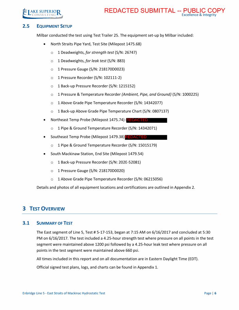
3.2 PRESSURIZATION AND PV PLOT
A 0% hold on all charts began at 4:00 AM on 6/16/2017 and was completed at 4:30 AM. Once the 0%
hold was complete, line pressure of 562 psi was reintroduced to the recorders. Pressurization began at
5:07 AM, starting at a pressure of 562 psi.
At 5:14 AM, a 50% pressure of 620 psi was reached. A 15-minute hold was commenced at the 50%
pressure. At 5:31 AM, pressurization began to 75% with a starting pressure of 621 psi. A PV plot was
completed during pressurization from 50% to 75%. This PV plot resulted in an average of 49.9 strokes
per 10 psi, using a 0.258 gal/stroke pump, with a maximum of 52 and minimum of 46. Pressurization
rate did not exceed the outlined maximum of 10 psi/minute.
At 6:05 AM, a 75% pressure of 930 psi was reached. A 15-minute hold was commenced at the 75%
pressure. At 6:31 AM, pressurization began to strength test pressure with a starting pressure of 930
psi. A PV plot was completed during pressurization from 75% to strength test pressure. The PV plot
from 75% to strength test pressure resulted in an average of 49.7 strokes per 10 psi with a maximum
of 53 and minimum of 46. Pressurization rate did not exceed the outlined maximum of 10 psi/minute.
Figure 3. Pressure vs Volume Plot
REDACTED SUBMITTAL -- PUBLIC COPY
Excellence & Integrity
Enbridge Line 5 - East Straits of Mackinac Hydrostatic Test Page | 8
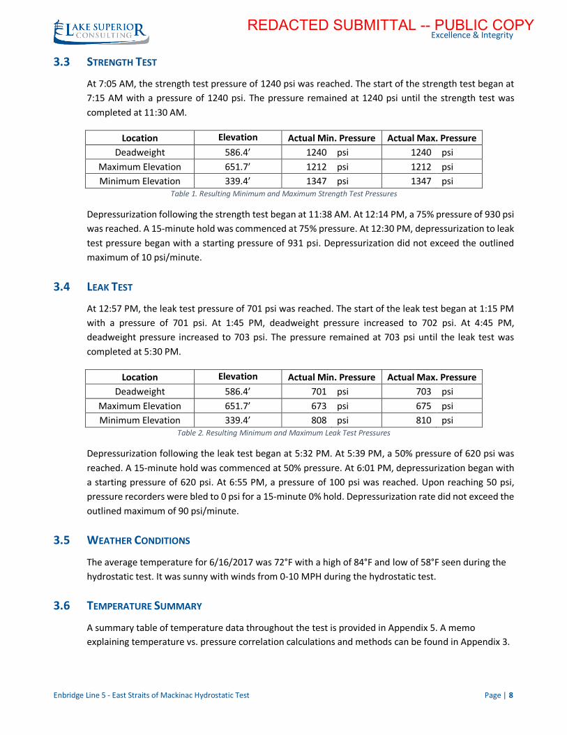
3.3 STRENGTH TEST
At 7:05 AM, the strength test pressure of 1240 psi was reached. The start of the strength test began at
7:15 AM with a pressure of 1240 psi. The pressure remained at 1240 psi until the strength test was
completed at 11:30 AM.
Location Elevation Actual Min. Pressure Actual Max. Pressure
Deadweight 586.4’ 1240 psi 1240 psi
Maximum Elevation 651.7’ 1212 psi 1212 psi
Minimum Elevation 339.4’ 1347 psi 1347 psi Table 1. Resulting Minimum and Maximum Strength Test Pressures
Depressurization following the strength test began at 11:38 AM. At 12:14 PM, a 75% pressure of 930 psi
was reached. A 15-minute hold was commenced at 75% pressure. At 12:30 PM, depressurization to leak
test pressure began with a starting pressure of 931 psi. Depressurization did not exceed the outlined
maximum of 10 psi/minute.
3.4 LEAK TEST
At 12:57 PM, the leak test pressure of 701 psi was reached. The start of the leak test began at 1:15 PM
with a pressure of 701 psi. At 1:45 PM, deadweight pressure increased to 702 psi. At 4:45 PM,
deadweight pressure increased to 703 psi. The pressure remained at 703 psi until the leak test was
completed at 5:30 PM.
Location Elevation Actual Min. Pressure Actual Max. Pressure
Deadweight 586.4’ 701 psi 703 psi
Maximum Elevation 651.7’ 673 psi 675 psi
Minimum Elevation 339.4’ 808 psi 810 psi Table 2. Resulting Minimum and Maximum Leak Test Pressures
Depressurization following the leak test began at 5:32 PM. At 5:39 PM, a 50% pressure of 620 psi was
reached. A 15-minute hold was commenced at 50% pressure. At 6:01 PM, depressurization began with
a starting pressure of 620 psi. At 6:55 PM, a pressure of 100 psi was reached. Upon reaching 50 psi,
pressure recorders were bled to 0 psi for a 15-minute 0% hold. Depressurization rate did not exceed the
outlined maximum of 90 psi/minute.
3.5 WEATHER CONDITIONS
The average temperature for 6/16/2017 was 72°F with a high of 84°F and low of 58°F seen during the
hydrostatic test. It was sunny with winds from 0-10 MPH during the hydrostatic test.
3.6 TEMPERATURE SUMMARY
A summary table of temperature data throughout the test is provided in Appendix 5. A memo
explaining temperature vs. pressure correlation calculations and methods can be found in Appendix 3.
REDACTED SUBMITTAL -- PUBLIC COPY
Excellence & Integrity
Enbridge Line 5 - East Straits of Mackinac Hydrostatic Test Page | 9
4 TEST ACCEPTANCE
4.1 STRENGTH TEST
Pressure maintained constant at 1240 psi during the 4.25-hour Strength Test. Pressure within an
isolated test segment is influenced by the temperature of the water within that segment, and the
gross amount of pressure change across the segment depends on the length of pipe exposed to each
heating/cooling influence, as shown further in Appendix 3, 3. Temperature vs Pressure Correlation.
During the strength test, the following influences were present:
• Fluctuations in temperature were observed in the above grade pipe temperature and below
grade pipe temperature. A slight decrease of less than 1oF was observed in the below grade
pipe temperature. An increase in above grade pipe temperature of approximately 2oF was
observed throughout the Strength Test. The length of below grade pipe is significantly greater
than the above grade pipe so any change in temperature of below grade pipe will influence
pressure much more than temperature changes in the above grade pipe. The net change in
pressure resulting from the temperature change in above grade and below grade pipe results
in less than a 0.5 psi decrease in pressure.
• The effect of the lake water on the submerged portion of the pipe has the most significant
effect on changes in pressure. The lake water temperature recordings fluctuated
approximately ~0.3oF from the beginning to the end of the strength test. If this temperature
change had transferred directly to the water inside the pipe, the resulting pressure change
would have been a 2 psi fluctuation.
The minimal change in lake water temperature in combination with the above and below grade pipe
temperatures result in a zero-net pressure effect on the pipeline. A 0 psi pressure change during the
Strength Test is within the resolution of the instrumentation and within the calculated response due to
the observed temperature changes.
Strength Test pressure was held at a 1240 psi for a duration of 4 hours and 15 minutes. Pressures
remained within the allowable Strength Test range of 1229 psi – 1249 psi, and a minimum of a 4.25-
hour hold was completed.
4.2 LEAK TEST
Pressure increased 2 psi during the 4.25-hour Leak Test. As with the strength test, pressure
fluctuations were influenced by corresponding fluctuations in temperature during the leak test. During
the leak test, the following influences were present:
• An average of 0.5oF decrease was observed on the below grade pipe during the 4.25-hour Leak
Test, which corresponds to a 0.5 psi decrease in pressure.
• The above grade pipe temperature increased on average approximately 3oF, which
corresponds to a 0.6 psi increase in pressure.
REDACTED SUBMITTAL -- PUBLIC COPY
Excellence & Integrity
Enbridge Line 5 - East Straits of Mackinac Hydrostatic Test Page | 10
• The lake water temperature recordings fluctuated approximately ~0.4oF throughout the Leak
Test with an upward trend. If this temperature change had transferred directly to the water
inside the pipe, the result would have been a 3 psi increase.
The net effect of minimal temperature fluctuations throughout the Leak Test had a slight upward trend
resulting from the slight increase in observed water temperature recordings. The pressure increase of
2 psi during the Leak Test is within the resolution of the instrumentation and within the calculated
response due to the observed temperature changes.
Leak Test pressure held at a minimum of 701 psi and a maximum of 703 psi for a duration of 4 hours
and 15 minutes. Pressures remained within the allowable Leak test range of 689 psi – 709 psi, and a
minimum of a 4.25-hour hold was completed.
4.3 TEST CRITERIA CONFIRMATION
4.3.1 TEST PERIOD
The test was conducted by completing the Strength Test and Leak Test consecutively over a
continuous 8-hour period.
1. The Strength Test was conducted with test pressure maintained at 2 X MOP (>1200 psi) for 4
hours 15 minutes at all locations of the test segment.
2. Upon completion of the Strength Test, the Leak Test was conducted with the test pressure
maintained at 1.1 X MOP (>660 psi) for 4 hours 15 minutes at all locations of the test segment.
3. No water was added to or withdrawn from any line segment during the test period.
4.3.2 LINE FAILURE
No line failures or evidence of leaks occurred during the hydrostatic pressure test.
REDACTED SUBMITTAL -- PUBLIC COPY

Excellence & Integrity
Enbridge Line 5 - East Straits of Mackinac Hydrostatic Test
APPENDIX 1 – TEST RECORDS
1 PRESSURE TEST PLAN – NORTH STRAITS SITE
Accepted Pressure Test Plan with all materials associated with the North Straits Site.
2 PRESSURE TEST PLAN – MACKINAW STATION SITE
Accepted Pressure Test Plan with all materials associated with the Mackinaw Station Site.
3 701 PRESSURE TEST REPORT
Signed copy of the 701 Pressure Test Report form.
4 702 PRESSURE TEST DATA SHEET
Signed copy of the 702 Pressure Test Data Sheets.
5 PV PLOT
Copy of the PV Plot graph and PV Plot data sheet.
6 CHARTS
Signed copy of all test charts.
7 TEMPERATURE PROBE GRAPHS
Signed copy of all temperature probe graphs.
8 704 PRESSURE TEST CHECKLIST
Copy of the 704 Pressure Test Checklist form.
9 705 PRESSURE TEST REQUIREMENTS CHECKLIST
Copy of the 705 Pressure Test Requirements Checklist form.
REDACTED SUBMITTAL -- PUBLIC COPY
Excellence & Integrity
Enbridge Line 5 - East Straits of Mackinac Hydrostatic Test
APPENDIX 2 – TEST EQUIPMENT & OPERATOR QUALIFICATIONS
1 TEST SCHEMATIC
Drawing D-3.04-1783-E-165 – EAST with overview of all equipment locations and serial numbers.
2 PHOTO REPORT
Photo report of all test equipment outlined in above schematic.
3 EQUIPMENT CERTIFICATIONS
Equipment certifications for all test equipment. All equipment certifications were verified as being within
the calibration data and accuracy range outlined in the Project Hydrotest Plan (Appendix 3).
4 HYDROTEST OPERATOR QUALIFICATIONS
Copy of Milbar personnel operator qualifications.
REDACTED SUBMITTAL -- PUBLIC COPY
Excellence & Integrity
Enbridge Line 5 - East Straits of Mackinac Hydrostatic Test
APPENDIX 3 – PROJECT SPECIFIC HYDROTEST PLANS
1 PROJECT HYDROTEST PLAN
Version No. 2.3 of the official Project Hydrotest Plan.
2 HYDROTEST PLAN SUBMITTED TO EPA
Version No. 2 (4/25/2017) of the official Line 5 Straits of Mackinac Hydrostatic Pressure Test Plan.
3 TEMPERATURE VS. PRESSURE CORRELATION
Document outlining how the temperature pressure calculations were completed.
REDACTED SUBMITTAL -- PUBLIC COPY
Excellence & Integrity
Enbridge Line 5 - East Straits of Mackinac Hydrostatic Test
APPENDIX 4 – TEST MEDIUM
1 WATER ACQUISITION
Water was acquired from the City of St. Ignace, MI from a fire hydrant at (45°51’12.37” N, 84°46’13.91”
W). A report of the initial quality of water from the City of St Ignace is included below. Water was then
trucked to the North Straits Pipeyard and unloaded into an Above Ground Storage tank (AST). The AST was
73ft in diameter and had a capacity of 9000BBLS.
2 LINE FILL
Line fill of the East Segment of the Line 5 Straits Hydrotest began on 6/13/2017 at 8:50 PM. Line fill was
completed behind a pig to ensure a solid water column from trap to trap during line fill, and ensure all air
was purged from the pipeline. Enbridge operations set up temporary venting locations on the 2” valves to
bleed air out of the station piping. Once venting was completed the line was packed out to 260 psi by the
fill pumps. Line Fill was complete on 6/14/2017 at 4:58 AM.
The calculated volume of water required for line fill was 305,900 gallons. A total of 305,200 gallons were
used to complete pipe fill, station piping fill, and initial pack out of the segment, according to the flow
meter on the fill pump. The initial height of the water in the AST was 11ft 1” and a final height of 22” was
observed resulting in a total of 299,600 gallons used. An additional 10,000 gallons was added to the AST
prior to line fill resulting in a total volume of 309,600 gallons. The additional volume was used to flood the
line fill piping.
During line fill, Praxair “Seeper Trace” tracer gas was injected in the first 20,000 gallons of water and the
last 28,000 gallons of water at a concentration of 7 PPM. This was designed to have gas entrained in all
above lake level piping. Also during line fill Milbar injected a fluorescein dye into the entire water column
at a concentration of 1GAL/1000BBLS. The “Seeper Trace” and dye were injected into the pipeline in
preparation of a leak event, but were not utilized on this hydrotest since no leaks were observed.
3 STABILIZATION
Water was injected into the pipeline at approximately 65oF to fill the pipeline. The ground temperature at
the below grade temperature sites was approximately 57oF. Line fill was completed at 4:58 AM,
6/14/2017, pressure was increased to 600 psi to allow beginning of stabilization at 7:36 AM,
6/14/2017. Pressure declined steadily at an average rate of less than 2 psi per hour until 7:30 AM,
6/15/2017. At 7:30 AM, 6/15/2017 pressure was 565 psi, over the next 21 hours a decline of only 3 psi was
observed. Referring to the below grade pipe and ground temperature data, the pipe temperature was seen
to be nearly equal to the ground temperature.
The minimal decrease in pressure (3 psi) in 21 hours preceding the start of test at 5:00 AM, 6/16/2017
combined with the minimal difference in pipe/ground temperature data indicated the water in the test
segment had stabilized with its environment. A total of 45 hours stabilization occurred from initial
pressurization to 600 psi (7:36 AM, 6/14/2017) to beginning of test sequence (5:00 AM, 6/16/2017).
Charts and graphs for stabilization are in Appendix 4 Attachments.
REDACTED SUBMITTAL -- PUBLIC COPY
Excellence & Integrity
Enbridge Line 5 - East Straits of Mackinac Hydrostatic Test
4 DEWATER AND TREATMENT
Once the East segment hydrotest was complete the south station piping was drained up using a vac truck.
The segment was then dewatered by pushing the water out of the pipeline with a pig, being pushed by
nitrogen from Mackinaw Station towards the North Straits Pipe Yard. Water flowed through temporary
piping at the North Straits Pipe Yard into 2 frac tanks. After the frac tanks water was treated by ProAct who
was subcontracted through UPI, the general contractor. ProAct used a carbon filtration system to remove
any remaining hydrocarbons and the fluorescent dye from the water before discharging into the Above
Ground Storage tank (AST). Water was then transported to the St. Ignace wastewater treatment facility for
disposal. A report of the final quality of water after filtration is included below.
5 PHOTO REPORT
Photo report of all test medium equipment.
REDACTED SUBMITTAL -- PUBLIC COPY
Excellence & Integrity
Enbridge Line 5 - East Straits of Mackinac Hydrostatic Test
APPENDIX 5 –SYSTEM ISOLATION AND VALVE POSITIONS
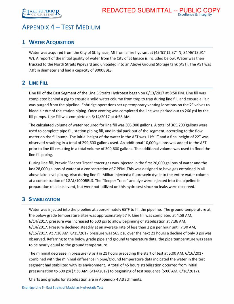
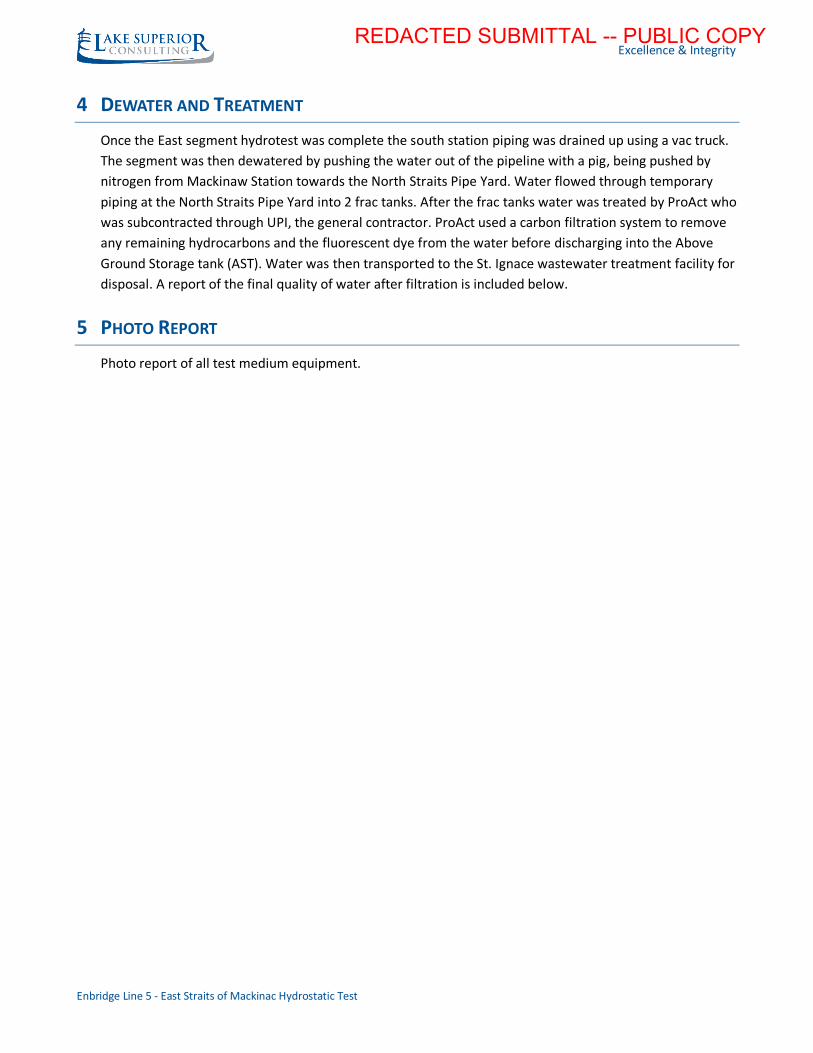
1 SYSTEM ISOLATION
The East Segment of Line 5 across the Straits of Mackinac was isolated on the north end by removing
flanged valve 5.1-V-1 and installing blind flanges. It was isolated on the south end by removing flanged
check valve 5.1-CV-1 and installing blind flanges. All 2” auxiliary connections on the traps and station
piping were removed and isolated with blind flanges or plugs.
2 VALVE POSITIONS
All valve positions were confirmed to be in the partially open position by Enbridge Operations to Kory
Johnson (Test Engineer) prior to the start of test. Valves were set in the partially open position to include
the body of the valve in the hydrotest.
Figure 5: North Straits Pipeyard Isolation Figure 7: North Straits Pipeyard Isolation
Figure 6: Mackinaw Station Isolation Figure 4: Mackinaw Station Isolation
REDACTED
REDACTED
REDACTED SUBMITTAL -- PUBLIC COPY
Excellence & Integrity
Enbridge Line 5 - East Straits of Mackinac Hydrostatic Test
APPENDIX 6 –TEMPERATURE SUMMARY
1 TEMPERATURE DATA SUMMARY TABLES
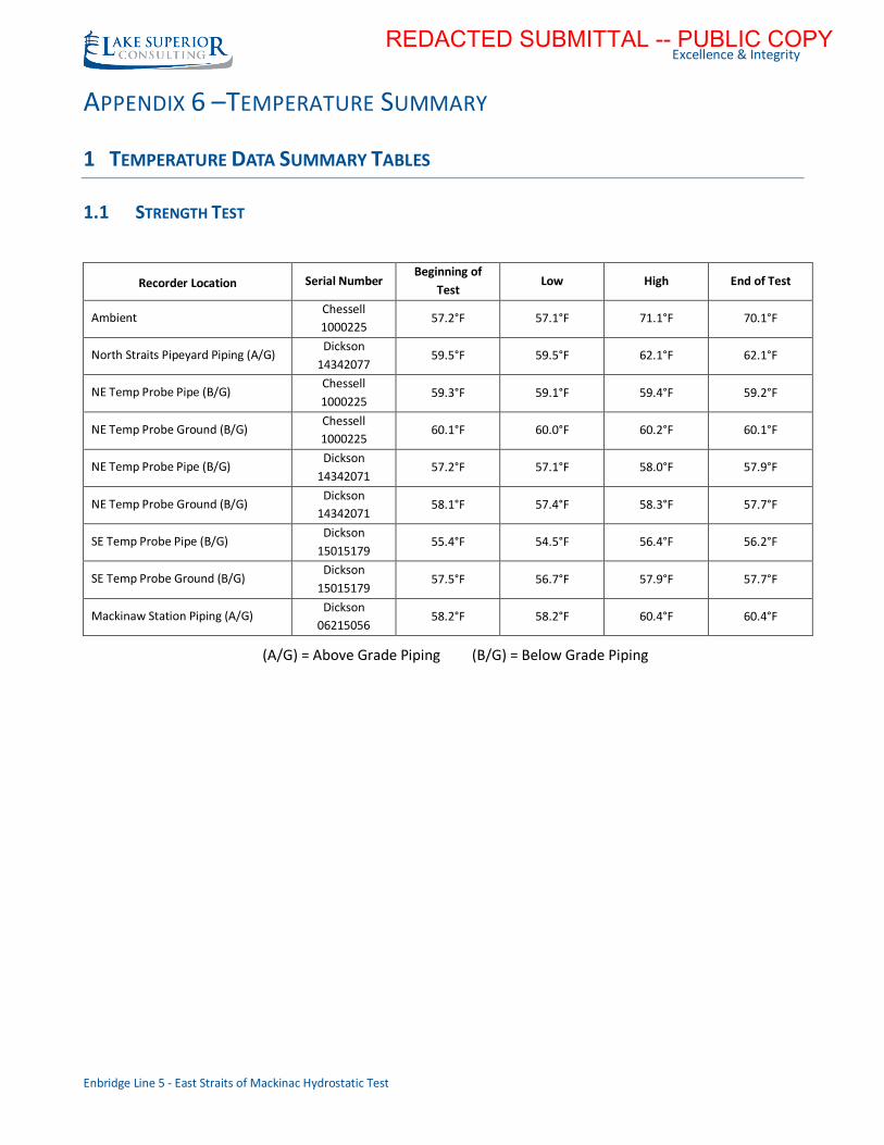
1.1 STRENGTH TEST
Recorder Location Serial Number Beginning of
Test Low High End of Test
Ambient Chessell
1000225 57.2°F 57.1°F 71.1°F 70.1°F
North Straits Pipeyard Piping (A/G) Dickson
14342077 59.5°F 59.5°F 62.1°F 62.1°F
NE Temp Probe Pipe (B/G) Chessell
1000225 59.3°F 59.1°F 59.4°F 59.2°F
NE Temp Probe Ground (B/G) Chessell
1000225 60.1°F 60.0°F 60.2°F 60.1°F
NE Temp Probe Pipe (B/G) Dickson
14342071 57.2°F 57.1°F 58.0°F 57.9°F
NE Temp Probe Ground (B/G) Dickson
14342071 58.1°F 57.4°F 58.3°F 57.7°F
SE Temp Probe Pipe (B/G) Dickson
15015179 55.4°F 54.5°F 56.4°F 56.2°F
SE Temp Probe Ground (B/G) Dickson
15015179 57.5°F 56.7°F 57.9°F 57.7°F
Mackinaw Station Piping (A/G) Dickson
06215056 58.2°F 58.2°F 60.4°F 60.4°F
(A/G) = Above Grade Piping (B/G) = Below Grade Piping
REDACTED SUBMITTAL -- PUBLIC COPY
Excellence & Integrity
Enbridge Line 5 - East Straits of Mackinac Hydrostatic Test
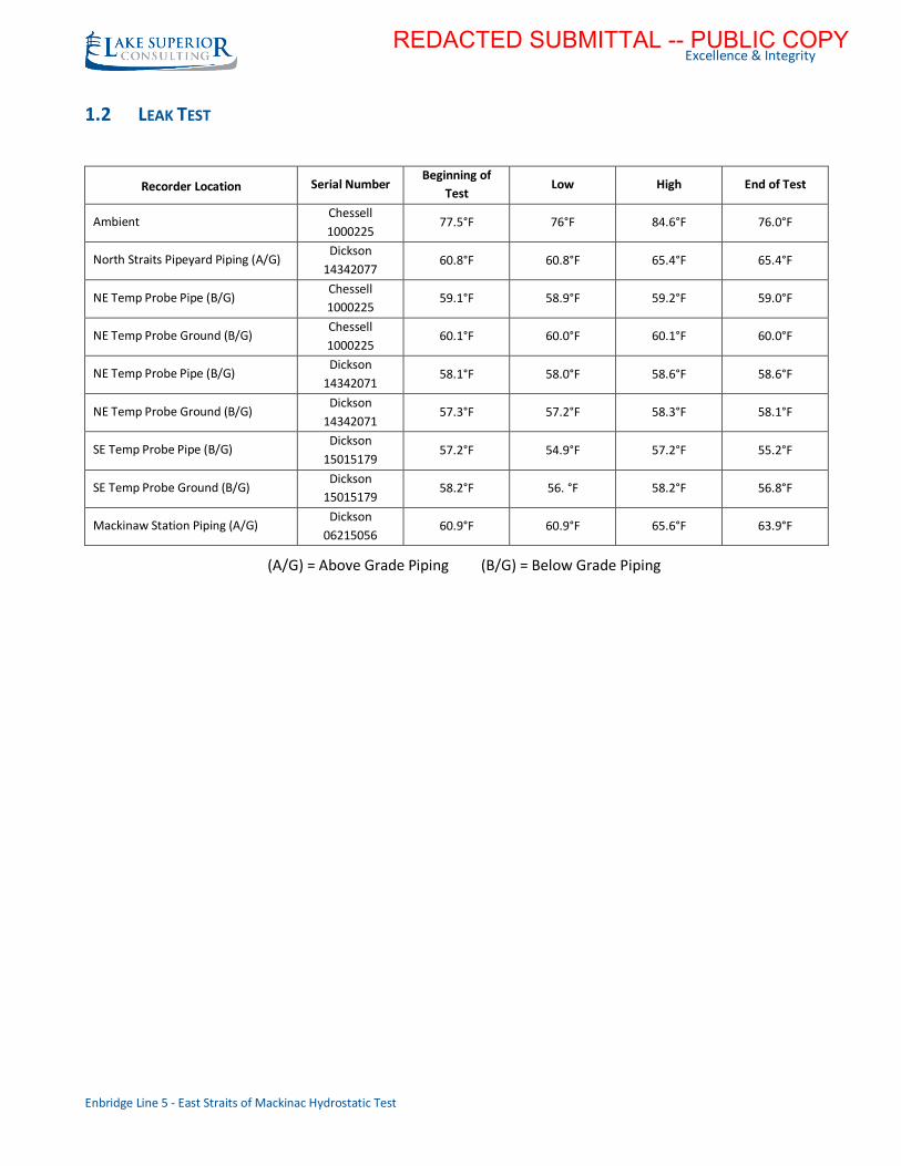
1.2 LEAK TEST
Recorder Location Serial Number Beginning of
Test Low High End of Test
Ambient Chessell
1000225 77.5°F 76°F 84.6°F 76.0°F
North Straits Pipeyard Piping (A/G) Dickson
14342077 60.8°F 60.8°F 65.4°F 65.4°F
NE Temp Probe Pipe (B/G) Chessell
1000225 59.1°F 58.9°F 59.2°F 59.0°F
NE Temp Probe Ground (B/G) Chessell
1000225 60.1°F 60.0°F 60.1°F 60.0°F
NE Temp Probe Pipe (B/G) Dickson
14342071 58.1°F 58.0°F 58.6°F 58.6°F
NE Temp Probe Ground (B/G) Dickson
14342071 57.3°F 57.2°F 58.3°F 58.1°F
SE Temp Probe Pipe (B/G) Dickson
15015179 57.2°F 54.9°F 57.2°F 55.2°F
SE Temp Probe Ground (B/G) Dickson
15015179 58.2°F 56. °F 58.2°F 56.8°F
Mackinaw Station Piping (A/G) Dickson
06215056 60.9°F 60.9°F 65.6°F 63.9°F
(A/G) = Above Grade Piping (B/G) = Below Grade Piping
REDACTED SUBMITTAL -- PUBLIC COPY
Excellence & Integrity
Enbridge Line 5 - East Straits of Mackinac Hydrostatic Test
APPENDIX 7 – MICHIGAN TECHNOLOGICAL UNIVERSITY WATER
TEMPERATURE MEASUREMENTS
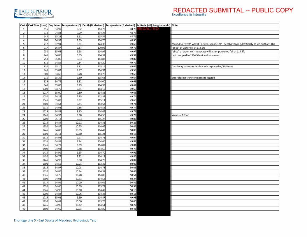
1 WATER TEMPERATURE OVERVIEW
The majority of the L5 Pipeline crossing the Straits of Mackinac is underwater so it was determined that
reference water temperature data would be beneficial in order to correlate trends in lake water
temperature versus trends in pressure throughout the duration of the hydrotest.
Michigan Technological University was brought on to the project to collect this data. The data was
gathered approximately every 15 minutes from a boat which was located at a location 50ft off of the
pipeline. The location was chosen to represent the average elevation of the below water piping. Data was
gathered by using a CastAway®-CTD instrument for gathering the temperature. Data was gathered during
the daytime on the day prior to the test (stabilization period) and during the hydrotest duration.
Note: Data was gathered only during times when weather conditions allowed.
2 DATA SUMMARY TABLE
Below is a table provided by Michigan Technological University, from 6/16/2017, summarizing the data
gathered during the hydrotest.
REDACTED SUBMITTAL -- PUBLIC COPY
Excellence & Integrity
Enbridge Line 5 - East Straits of Mackinac Hydrostatic Test
Cast # Cast Time (local) Depth (m) Temperature (C) Depth (ft, derived) Temperature (F, derived) Latitude (dd) Longitude (dd) Note
1 615 34.99 9.32 114.78 48.78
2 631 34.81 9.29 114.22 48.73
3 645 35.23 9.31 115.59 48.75
4 700 34.98 9.39 114.76 48.90
5 717 37.91 9.81 124.38 49.66 Moved to "west" waypt - depth (sonar) 124' - depths varying drastically as we drift at 1.0kt
6 717 36.87 9.87 120.96 49.76 "slice" of water col at 114.5ft
7 730 35.03 9.98 114.94 49.97 "slice" of water col - next cast will attempt to stop fall at 114.5ft
8 745 34.86 9.95 114.37 49.91 cast dropped to ~114.5 feet and recovered
9 759 35.00 9.93 114.82 49.87
10 816 34.84 9.84 114.30 49.72
11 830 35.10 9.81 115.16 49.65 CastAway batteries depleated - replaced w/ Lithiums
12 845 35.03 9.77 114.92 49.58
13 901 34.66 9.78 113.70 49.60
14 916 35.25 9.80 115.63 49.64 Error closing transfer message logged
15 929 34.75 9.82 114.00 49.68
16 945 35.05 9.79 114.98 49.62
17 1000 34.79 9.81 114.15 49.66
18 1017 35.00 9.80 114.81 49.63
19 1030 34.24 9.85 112.33 49.74
20 1045 35.09 9.82 115.11 49.68
21 1100 34.64 9.84 113.63 49.71
22 1115 34.93 9.86 114.58 49.74
23 1129 34.88 9.85 114.44 49.73
24 1145 34.92 9.88 114.56 49.79 Waves < 1 foot
25 1200 35.13 9.93 115.27 49.87
26 1215 34.84 10.12 114.32 50.21
27 1230 34.89 10.25 114.46 50.45
28 1245 34.89 10.05 114.47 50.09
29 1300 35.13 10.10 115.24 50.18
30 1315 34.98 9.97 114.78 49.94
31 1331 34.88 9.94 114.45 49.89
32 1345 34.77 9.89 114.09 49.81
33 1400 34.94 9.88 114.65 49.78
34 1416 34.96 9.95 114.70 49.91
35 1430 34.79 9.92 114.13 49.86
36 1445 34.98 9.90 114.75 49.82
37 1501 34.55 10.01 113.35 50.02
38 1516 34.97 10.03 114.73 50.05
39 1532 34.86 10.24 114.37 50.43
40 1546 34.75 10.28 114.00 50.51
41 1600 34.91 10.13 114.54 50.24
42 1615 34.95 10.29 114.66 50.52
43 1630 34.66 10.19 113.73 50.34
44 1645 34.90 10.10 114.49 50.18
45 1700 34.84 10.06 114.32 50.11
46 1715 35.01 9.99 114.87 49.98
47 1730 34.67 10.00 113.76 50.00
48 1746 34.90 10.12 114.51 50.22
49 1800 34.69 10.23 113.80 50.41
REDACTED
REDACTED SUBMITTAL -- PUBLIC COPY

![Straits of Mackinac - Nautical Charts & · PDF fileStraits of Mackinac . ... harbor blueprints can be obtained at the dock office on the south side of ... Á v]vP UZÌ }vÀ]P }vv](https://img.pdfslide.us/doc/110x75/5aa132b77f8b9aa0108b7074/straits-of-mackinac-nautical-charts-of-mackinac-harbor-blueprints-can-be.jpg)