Embed Size (px)
Citation preview

Sinclair 1 21st Annual AIAA/USU
Conference on Small Satellites
SSC07-X-3
ENABLING REACTION WHEEL TECHNOLOGY FOR HIGH PERFORMANCE
NANOSATELLITE ATTITUDE CONTROL
Doug Sinclair
Sinclair Interplanetary
268 Claremont Street, Toronto, Ontario, Canada, M6J 2N3
Tel: 647-286-3761; Fax: 775-860-5428; Web: www.sinclairinterplanetary.com
C. Cordell Grant, Robert E. Zee
Space Flight Laboratory
University of Toronto Institute for Aerospace Studies
4925 Dufferin Street, Toronto, Ontario, Canada, M3H 5T6
Tel: 416-667-7700; Fax: 416-667-7799; Web: www.utias-sfl.net
[email protected], [email protected]
ABSTRACT
To date nanosatellites have primarily relied on magnetic stabilization which is sufficient to meet thermal and
communications needs but is not suited for most payloads. The ability to put one, or even three, reaction wheels on
a spacecraft in the 2-20 kg range enables new classes of mission. With reaction wheels and an appropriate sensor
suite a nanosatellite can point in arbitrary directions with accuracies on the order of a degree. Sinclair
Interplanetary, in collaboration with the University of Toronto Space Flight Laboratory (SFL), has developed a
reaction wheel suitable for very small spacecraft. It fits within a 5 x 5 x 4 cm box, weighs 185 g, and consumes only
100 mW of power at nominal speed. No pressurized enclosure is required, and the motor is custom made in one
piece with the flywheel. The wheel is in mass production with sixteen flight units delivered, destined for the CanX
series of nanosatellites. The first launch is expected in 2007. Future missions that will make use of these wheels
include CanX-3 (BRITE), which will make astronomical observations that cannot be duplicated by any existing
terrestrial facility, and CanX-4 and -5, which will demonstrate autonomous precision formation flying.
INTRODUCTION
Precise three-axis stabilization is a virtual necessity for
any mission that requires a pointed instrument, whether
the application is Earth observation, communications or
astronomy. Until recently, the technology for precise
pointing (a degree or less) has not been available for
small missions. The Microvariability and Oscillations
of STars space telescope was among the first to
demonstrate arcsecond-level attitude stability on a 53-
kilogram microsatellite platform. For microsatellites,
the advent of precise three-axis attitude control has
greatly expanded their utility. For nanosatellites, or
satellites under 10 kilograms (or 20 kilograms,
depending upon the naming convention used), the
enabling technology for precise three-axis attitude
control has so far been nascent. One key enabling
technology is the reaction wheel. Although various
organizations have attempted to create reaction wheels
for nanosatellites, subject to the physical and financial
constraints of typical nanosatellite programs, there are
currently no products on the market that fill this need.
In recognition of this need, and in order to meet the
stringent requirements of missions under development
at the University of Toronto’s Space Flight Laboratory
(SFL), Sinclair Interplanetary has developed a low-cost,
scalable/customizable reaction wheel for nanosatellites
in collaboration with SFL. At present, sixteen wheels
have been produced to support three nanosatellite
missions under development at SFL: CanX-2
(Canadian Advanced Nanospace eXperiment 2),
BRIght Target Explorer (BRITE) Constellation (aka
CanX-3), and CanX-4/CanX-5 formation flying.
CanX-2, a 3.5 kg, 10x10x34cm satellite launching from
India in 2007 aboard the Polar Satellite Launch
Vehicle, is carrying a reaction wheel prototype for
testing in space. BRITE Constellation and the CanX-
4&5 formation flying mission involve multiple 20cm
cube satellites, each equipped with three reaction
wheels for precise pointing. BRITE Constellation is a
space astronomy mission that requires 1.5 arcminute
pointing stability, while CanX-4 and CanX-5 require
relatively fast slews (90º in 60 seconds) to point
thrusters for orbital maintenance. Neither mission
Sinclair 2 21st Annual AIAA/USU
Conference on Small Satellites
would be possible without nanosatellite reaction
wheels.
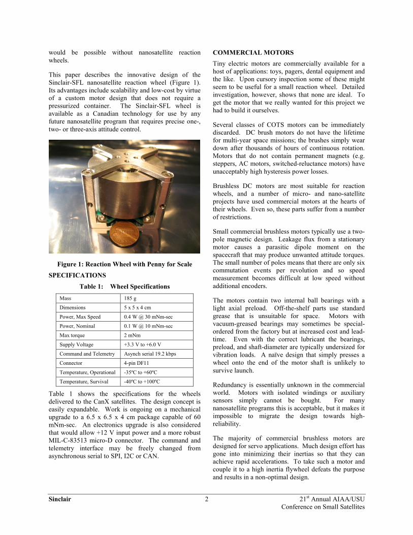
This paper describes the innovative design of the
Sinclair-SFL nanosatellite reaction wheel (Figure 1).
Its advantages include scalability and low-cost by virtue
of a custom motor design that does not require a
pressurized container. The Sinclair-SFL wheel is
available as a Canadian technology for use by any
future nanosatellite program that requires precise one-,
two- or three-axis attitude control.
Figure 1: Reaction Wheel with Penny for Scale
SPECIFICATIONS
Table 1: Wheel Specifications
Mass 185 g
Dimensions 5 x 5 x 4 cm
Power, Max Speed 0.4 W @ 30 mNm-sec
Power, Nominal 0.1 W @ 10 mNm-sec
Max torque 2 mNm
Supply Voltage +3.3 V to +6.0 V
Command and Telemetry Asynch serial 19.2 kbps
Connector 4-pin DF11
Temperature, Operational -35ºC to +60ºC
Temperature, Survival -40ºC to +100ºC
Table 1 shows the specifications for the wheels
delivered to the CanX satellites. The design concept is
easily expandable. Work is ongoing on a mechanical
upgrade to a 6.5 x 6.5 x 4 cm package capable of 60
mNm-sec. An electronics upgrade is also considered
that would allow +12 V input power and a more robust
MIL-C-83513 micro-D connector. The command and
telemetry interface may be freely changed from
asynchronous serial to SPI, I2C or CAN.
COMMERCIAL MOTORS
Tiny electric motors are commercially available for a
host of applications: toys, pagers, dental equipment and
the like. Upon cursory inspection some of these might
seem to be useful for a small reaction wheel. Detailed
investigation, however, shows that none are ideal. To
get the motor that we really wanted for this project we
had to build it ourselves.
Several classes of COTS motors can be immediately
discarded. DC brush motors do not have the lifetime
for multi-year space missions; the brushes simply wear
down after thousands of hours of continuous rotation.
Motors that do not contain permanent magnets (e.g.
steppers, AC motors, switched-reluctance motors) have
unacceptably high hysteresis power losses.
Brushless DC motors are most suitable for reaction
wheels, and a number of micro- and nano-satellite
projects have used commercial motors at the hearts of
their wheels. Even so, these parts suffer from a number
of restrictions.
Small commercial brushless motors typically use a two-
pole magnetic design. Leakage flux from a stationary
motor causes a parasitic dipole moment on the
spacecraft that may produce unwanted attitude torques.
The small number of poles means that there are only six
commutation events per revolution and so speed
measurement becomes difficult at low speed without
additional encoders.
The motors contain two internal ball bearings with a
light axial preload. Off-the-shelf parts use standard
grease that is unsuitable for space. Motors with
vacuum-greased bearings may sometimes be special-
ordered from the factory but at increased cost and lead-
time. Even with the correct lubricant the bearings,
preload, and shaft-diameter are typically undersized for
vibration loads. A naïve design that simply presses a
wheel onto the end of the motor shaft is unlikely to
survive launch.
Redundancy is essentially unknown in the commercial
world. Motors with isolated windings or auxiliary
sensors simply cannot be bought. For many
nanosatellite programs this is acceptable, but it makes it
impossible to migrate the design towards high-
reliability.
The majority of commercial brushless motors are
designed for servo applications. Much design effort has
gone into minimizing their inertias so that they can
achieve rapid accelerations. To take such a motor and
couple it to a high inertia flywheel defeats the purpose
and results in a non-optimal design.

Sinclair 3 21st Annual AIAA/USU
Conference on Small Satellites
CUSTOM MOTOR CONCEPT
Realizing that mating a low-inertia motor to a high-
inertia wheel makes no sense we attempted a different
tack. What if we could design a brushless DC motor
that was optimized for high inertia? If the inertia of the
motor itself is large enough then there is no need for a
separate wheel. The two concepts join into a single
rotor element.
The first step in the concept evolution is to turn the
traditional brushless motor configuration inside out.
The heavy magnets are now at a large radius from the
center so they contribute usefully to the inertia. The
windings are now on the outside of a cylindrical stator
instead of on the inside, making fabrication much
easier.
The second step is to spin the back-iron. The back-iron
on the outside of a conventional motor prevents field-
lines from leaving, increasing torque and suppressing
radiated emissions. It is normally subjected to rotating
magnetization, and thus must be made from ferrite or
laminated steel to prevent eddy-current losses. If the
back-iron is spun, however, it sees only DC
magnetization! There are no eddy-current or hysteresis
losses and it can be made from solid steel. A rotating
back-iron both increases the inertia and reduces the
motor’s magnetic losses.
The large inner circumference of the rotor allows many
poles to be comfortably spaced. More poles reduce
radiated magnetic fields, give more commutation events
from which speed can be determined, and push torque-
ripple up to higher frequencies. A sketch of the motor
concept is shown in Figure 2. For clarity a four-pole
motor is shown; flight-models use a ten-pole motor.
The red lines illustrate the magnetic field loops. Each
magnetic circuit travels approximately half its distance
in the rotor back-iron and half through the non-
magnetic stator and air-gap. The path reluctance is
high, and so large magnets are required to achieve high
field strength. As the magnets contribute usefully to the
rotor inertia this is not a particular problem.
Three-phase windings require three coils for each pole-
pair. The motor illustrated here has six coils for a four-
pole rotor. The flight motor have fifteen coils to go
with the ten-pole rotor. The coils are wound in slots on
a Delrin stator. Unlike the slots in a traditional steel
stator these slots serve no magnetic function – they
simply provide mechanical support for the wire.
N
N
S S
Rotor
Stator
Windings
Hall
Sensors (x3)
Figure 2: Magnetic Schematic of Motor
Three digital Hall-effect sensors are mounted to the
stator behind the windings. They detect the passage of
the rotor magnets and are used for both commutation
and for speed measurement.
MAGNETIC DESIGN
Once the concept was developed there were
quantitative design considerations. How many poles
should there be? How much clearance should there be
between rotor and stator? How many turns of wire are
needed, and of what gauge?
Precise analytical modeling is very difficult. The
problem is three-dimensional and the B-H curves of the
magnets are non-linear. Sophisticated finite-element
tools are available that might be used, but we took a
much simpler approach to the engineering.
For the first pass, a paper-and-pencil analysis of the
magnetic fields was performed. The field shapes were
sketched heuristically, and the resulting geometry used
to determine the strengths. This gave us confidence
that the design was feasible, and in the end proved to be
remarkably accurate.
The second pass was performed empirically. It turns
out that a small metalworking lathe is an invaluable tool
for prototyping reaction wheels. It can obviously be
used to make test parts. Once that is done, however, it
can be used experimentally. A test rotor complete with
magnets is chucked into the lathe and spun. A small
wire coil of known dimensions is attached to a wooden
stick which is clamped into the lathe’s tool holder. An
oscilloscope measures the back-EMF, from which
dB/dt can be calculated. The coil can be precisely

Sinclair 4 21st Annual AIAA/USU
Conference on Small Satellites
translated using the lathe’s handwheels, and so the field
at different points inside the rotor can be mapped.
Figure 3: Lathe as Test Instrument
In this special case we feel that experimentation was
faster and cheaper than computer modeling, with added
confidence that the data reflects reality.
WINDINGS
An ideal brushless DC motor should exhibit an equal
sinusoidal back-EMF voltage waveform in each phase.
This motor is far from ideal. The discrete spacing of
the poles and the windings leads to third-order
harmonics. The manual winding process leads to
certain phases having higher back-EMF amplitudes
than others. Building a high-performance wheel
requires accounting for these non-idealities.
A consequence of the poor phase-to-phase voltage
match is that a ∆-winding configuration is impossible. ∆-winding requires that the sum of the three winding voltages is always zero. When it is not, circulating
currents develop in the coils which contribute a drag
torque. Instead this motor is Y-wound. It eliminates
circulating currents at the cost of slightly less efficient
copper usage.
Each phase is composed of two conductors wound
bifilar and connected in parallel at the end points. This
provides redundancy in the event of wire breakage. By
using two smaller wires instead of one of a heavier
gauge the eddy currents in the copper are reduced and
thus the drag torque is decreased.
SOFTWARE
The reaction wheel incorporates a mixed-signal
microcontroller as central part of its electronics. This
replaces many of the analog functions in a traditional
wheel and leads to a radical decrease in parts count.
Figure 4 shows a block diagram of the software in the
microcontroller when configured as a closed-loop speed
servo. There are two nested feedback systems: a high-
rate power-control loop and a low-rate speed-control
loop.
The power-control loop occupies the top-right quadrant
of the figure. The microprocessor’s ADC is used to
sample the instantaneous current and voltage in the
motor. These readings are multiplied, subtracted from
the power setpoint, and fed into a saturating integral
controller. The output goes into a DAC that drives the
motor’s analog pulse-width modulator circuits.
ADC
ADC
Current Sensor
Voltage Sensor
DAC To Drive PWM∫
Power Estimate
Hall Sensors
Commutation
TableTo Drive FETs
PID
Speed
Estimator
Speed
Command
Speed
Telemetry
Serial Packet
Communications
+ +
- -
Figure 4: Speed-Mode Software Block Diagram

Sinclair 5 21st Annual AIAA/USU
Conference on Small Satellites
This software block executes at a rate of 55 kHz, phase-
locked to the 440 kHz switching PWM. By controlling
the motor power, instead of the more common current
or voltage, low torque ripple is maintained even with
non-ideal winding back-EMF waveforms. The
algorithm uses only fixed-point arithmetic and is hand-
coded in assembly language to achieve the required
speed.
The speed-control loop runs at a more leisurely 93 Hz
and is coded in C with floating-point arithmetic.
Hardware capture peripherals detect the transition-times
of the Hall sensors to a resolution of 200 nsec. By
measuring the time taken for a complete 360º wheel
rotation the instantaneous speed can be precisely
estimated. In particular, measurement over a full circle
cancels any errors due to magnet irregularities or Hall
sensor placement. The wheel speed is subtracted from
the speed setpoint and fed into a PID controller. The
output of this controller is used as the setpoint input of
the power-control loop.
On the left of the figure is the communications block.
All commands and telemetry flow through the packet
communications logic. A wide variety of telemetry is
available in addition to speed: voltage, current,
temperature, and a host of software status values.
Similarly, commands may be used to adjust controller
gains and saturation limits. Other operating modes are
also available. Some spacecraft may prefer to operate
in closed-loop torque mode, while open-loop modes
were used during development.
The operating software for the wheel is stored in on-
chip Flash memory. The packet communications driver
can be used to upload new programs that can be run on
command. This allows software to be patched on-orbit
if need be. The communications code itself cannot be
modified, and the spacecraft can return the wheel to a
known-good state at any time by a power cycle. If
erroneous software is accidentally loaded it can be
erased and rewritten without risk.
A final feature of the wheel software is the built-in test
mode. The wheel can be commanded to execute a
standard test sequence with a duration of several
minutes. The test measures a number of critical
variables: speed tracking error, bearing friction, and
winding resistance of each phase. The sequence is used
during manufacture after assembly, and then again after
vibration and thermal cycles. It can be run at the
spacecraft level after integration, and again after
TVAC. It can even be run on-orbit. The single test
sequence makes it easy to immediately compare before
and after data to detect changes in wheel performance.
Such automation is fiscally necessary when building a
large number of parts for low-cost missions.
STRUCTURE
The wheel is held in an open box-shaped frame which
supports the bearings, electronics and motor. The
trade-off between a closed container and an open frame
is interesting.
Many small satellite wheels use a hermetic housing
filled with a low-pressure gas. The internal atmosphere
allows the use of bearing lubricants with modest vapour
pressures as well as protecting parts from
contamination or damage.
By forgoing the enclosure we have been forced to use
vacuum-compatible lubricant in the bearings. These
greases tend to be quite thick, and they increase the
friction losses at a given speed. However the lack of a
container means that the wheel diameter can be
increased and still remain within the target footprint.
Increased diameter leads to greatly increased inertia,
which in turn means that the wheel can operate at lower
speed for a given angular momentum. Comparing a
high-speed bearing with regular lubricant to a low-
speed bearing with vacuum lubricant the frictional
losses are similar.
There are many advantages to an open-frame wheel.
The structure mass drops radically. We need no fill
valves, or other fittings to pump out air during
integration. There is no seal-leak failure mode, and no
need for an internal pressure telemetry point. There is
no windage loss on-orbit (though there is considerable
aerodynamic loss in the lab).
Most wheels only have mounting points on the bottom
plate, making it difficult to arrange three orthogonal
units without extensive brackets. By replacing the
container with an open frame we have added threaded
hardpoints on three additional faces giving much more
mounting flexibility.
The obvious down-side to an open concept wheel is its
vulnerability to external disturbance. This design is
robust against moderate chemical and dust
contamination. It uses no optical encoders, passivates
all metal surfaces, and uses shielded bearings with
fluorinated lubricant. The most serious threat is that a
large object in the spacecraft could get loose and press
against the rotor. Wire bundles in particular must be
carefully routed and restrained to prevent them from
coming into contact.
Sinclair 6 21st Annual AIAA/USU
Conference on Small Satellites
CONCLUSION
A number of groups, several involving the author, have
previously attempted to bring nanosatellite wheels to
market. They have produced limited quantities of flight
hardware but for various reasons the wheels have not
been commercially successful and have not been
available to small satellite designers. Now, with sixteen
delivered and interest from several other parties,
Sinclair Interplanetary and SFL believe that they have
succeeded. A wheel is now available to nanosatellite
builders at a price that is consistent with low-cost
research missions.
The key to our success has been to design the wheel
from the ground-up for simplicity. It does not use a
commercial motor, or any bought-in subassembly more
complex than a bearing or a computer chip. This
ensures complete control of the materials and processes
and eliminates the chain of specialized suppliers that
might otherwise drive the cost and the lead-time.
Experience shows that the labour to build such a unit is
no greater than that required to assemble a traditional
wheel from more complex integrated parts.
In the past ten years we have seen a host of new
missions opened up for microsatellites with the advent
of reaction wheels in the ~1 kg class. Space astronomy,
earth observation and narrow-spot communication
payloads which were traditionally reserved for very
large busses are now feasible for spacecraft in the 30 –
100 kg range. We have now introduced a wheel in the
0.2 kg class, and expect it to enable similar missions for
spacecraft in the 2 – 20 kg range. Already SFL is using
it for astronomy and formation-flying maneuvers. We
look forward to the missions that others may find for it.
ACKNOWLEDGEMENTS
The authors gratefully acknowledge the support of the
Ontario Centres of Excellence Inc. (ETech Division)
and the Canadian Space Agency.