Embed Size (px)
Citation preview
Enabling Multi-party 3D Tele-immersive Environments withViewCast
ZHENYU YANG, WANMIN WU, KLARA NAHRSTEDT
University of Illinois at Urbana-Champaign
and
GREGORIJ KURILLO, RUZENA BAJCSY
University of California at Berkeley
Three-dimensional tele-immersive (3DTI) environments have great potential to promote collaborative work amonggeographically distributed users. However, most existing 3DTI systems work with only two sites due to the hugedemand of resources and the lack of a simple yet powerful networking model to handle connectivity, scalability,and quality-of-service (QoS) guarantees.
In this paper, we explore the design space from the angle of multi-stream management to enable multi-party3DTI communication. Multiple correlated 3D video streams are employed to provide a comprehensive represen-tation of the physical scene in each 3DTI environment, and rendered together to establish a common cyberspaceamong all participating 3DTI environments. The existence of multi-stream correlation provides the unique oppor-tunity for new approaches in QoS provisioning. Previous work mostly concentrated on compression and adaptationtechniques on the per stream basis while ignoring the application layer semantics and the coordination requiredamong streams. We propose an innovative and generalized ViewCast model to coordinate the multi-stream contentdissemination over an overlay network. ViewCast leverages view semantics in 3D free-viewpoint video systems tofill the gap between the high-level user interest and the low-level stream management. In ViewCast, only the viewinformation is specified by the user/application, while the underlying control dynamically performs stream differ-entiation, selection, coordination and dissemination. We present the details of ViewCast and evaluate it throughboth simulation and 3DTI sessions among tele-immersive environments residing in different institutes across theInternet2. Our experimental results demonstrate the implementation feasibility and performance enhancement ofViewCast in supporting the multi-party 3DTI collaboration.
Categories and Subject Descriptors: C.2.3 [Computer-Communication Networks]: Network Operations;C.2.2 [Computer-Communication Networks]: Network Protocols; C.2.1 [Computer-Communication Net-works]: Network Architecture and Design
General Terms: design, performance, experimentation
Additional Key Words and Phrases: 3D tele-immersion, networking protocol, distributed multimedia system,multi-stream coordination, QoS adaptation, application level multicast
1. INTRODUCTION
Three-dimensional tele-immersive (3DTI) environments have great the potential to promote col-laborative work among geographically distributed users. Earlier research efforts [Daniilidis et al.2000; Kauff and Schreer 2002; Raskar et al. 1998] have illustrated the possible applications of
Author’s address: Z. Yang, W. Wu and K. Nahrstedt, University of Illinois at Urbana-Champaign, Departmentof Computer Science, 201 N. Goodwin, Urbana, IL 61801, U.S.A.; eMail: {zyang2, wwu23, klara}@uiuc.edu.Author’s address: G. Kurillo, R. Bajcsy, University of California at Berkeley, Department of Electrical Engineeringand Computer Sciences, 253 Cory Hall, Berkeley, CA 94720, U.S.A.; eMail: {gregorij, bajcsy}@eecs.berkeley.edu.This work was supported by the National Science Foundation (NSF SCI 05-49242 and NSF CNS 05-20182).Permission to make digital/hard copy of all or part of this material without fee for personal or classroom useprovided that the copies are not made or distributed for profit or commercial advantage, the ACM copyright/servernotice, the title of the publication, and its date appear, and notice is given that copying is by permission of theACM, Inc. To copy otherwise, to republish, to post on servers, or to redistribute to lists requires prior specificpermission and/or a fee.c© 200x ACM 1529-3785/200x/0700-0111 $5.00
ACM Transactions on Multimedia Computing, Communications and Applications, Vol. x, No. x, xx 200x, Pages 111–139.
112 · Z. Yang et al.
3DTI environments in various areas such as scientific research, medical science, artistic per-formance, education, physiotherapy, training, and entertainment, where a higher level of spatialinteractivity is desired. Meanwhile, the end-devices (e.g., 3D cameras and displays) that make thetele-immersive edge applications possible are becoming more available and deployable due to theadvances in hardware. Consequently, there have been various efforts to create tele-conferencingand tele-immersive environments [Baker et al. 2005; Chen 2001; Gharai et al. 2002; Ott andMayer-Patel 2004; Shi et al. 2004; Schreer et al. 2001]. The current approaches represent a verygood start for the next generation of tele-immersive systems with an ultimate goal of delivering3DTI experience to the broader audience.
However, disregarding the promise, extensive deployment of 3DTI environments is still hinderedby the problems pertaining to connectivity, scalability and quality-of-service (QoS) guarantees.There are two major deficiencies in the current work. First, most existing 3DTI systems either donot provide 3D multi-stream immersive content or require dedicated computing and networkingcomponents. We argue that with the advance of end-devices it is now practical to further extendthe application of 3DTI environments with general content creation and delivery infrastructures.Second, most existing systems only support the inter-connection of two parties across the Internet.Enabling multi-party 3DTI collaboration is challenging due to the huge demand in computingand networking resources.
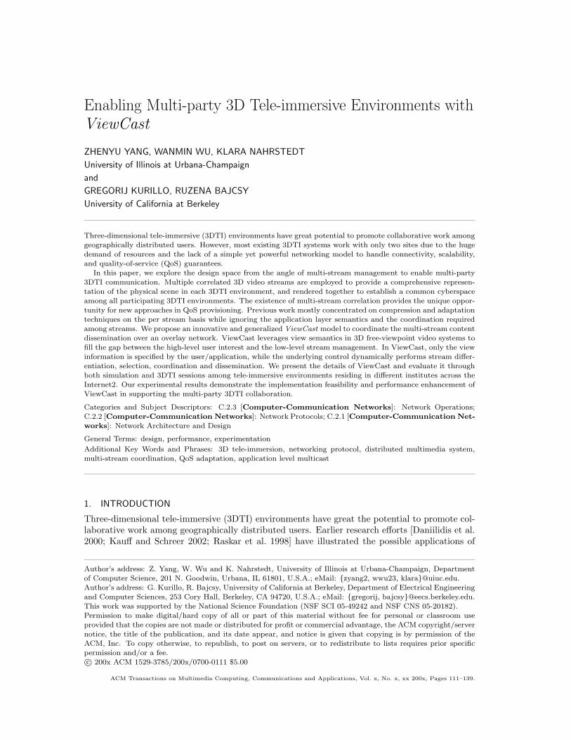
Figure 1 illustrates the multi-party 3DTI environments where remote users meet in a commonvirtual space and interact three-dimentionally. To accomplish that, the underlying system mustcapture, process, transmit, and render multiple 3D models with real-time performance. Hence,a critical question is how to organize the large volume of 3D visual data and their correspondingresources, over the current commercially available (COTS) computing and networking infras-tructures for the delivery of realistic immersive experience so that “everybody” would be able toinstall and enjoy the 3DTI environments for high quality tele-collaboration.
site 1
site 2
site 3
Fig. 1. Collaborative Multi-party 3DTI Environments
1.1 Characteristics and Challenges
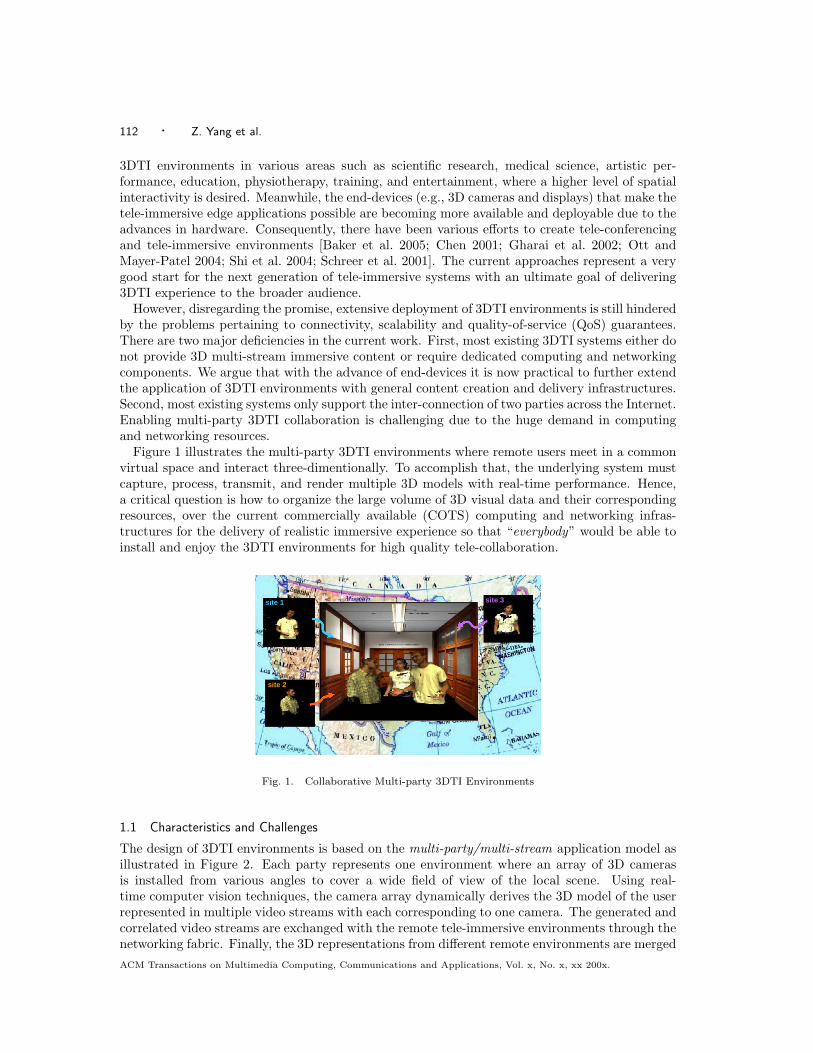
The design of 3DTI environments is based on the multi-party/multi-stream application model asillustrated in Figure 2. Each party represents one environment where an array of 3D camerasis installed from various angles to cover a wide field of view of the local scene. Using real-time computer vision techniques, the camera array dynamically derives the 3D model of the userrepresented in multiple video streams with each corresponding to one camera. The generated andcorrelated video streams are exchanged with the remote tele-immersive environments through thenetworking fabric. Finally, the 3D representations from different remote environments are mergedACM Transactions on Multimedia Computing, Communications and Applications, Vol. x, No. x, xx 200x.
Enabling Multi-party 3D Tele-immersive Environments with ViewCast · 113
and rendered together, creating a collaborative virtual space with the immersive awareness forevery participant.
SA,1
SA,2
SA,n
Party A
SB,1
SB,2
SB,m
Party B
SC,1
SC,2
SC,r
Party C
…
…
…network
SD,1
SD,2
SD,s
Party D
…
Streams from AStreams from BStreams from CStreams from D
Fig. 2. Multi-party/Multi-stream Application Model
In this paper, we explore the solution of enabling multi-party 3DTI communication from theangle of multi-stream management in content delivery. Our work is motivated by addressing thefollowing challenges.
—Large-volume Data. To achieve the realistic 3D visual effect, it is desirable to transmitmultiple video streams from each 3DTI environment in one communication session. In ourexperimental system [Yang et al. 2005; TEEVE 2006], one uncompressed 3D video stream hasthe basic rate over 30 Mbps (at the resolution of 320 × 240 pixels per 3D image frame and10 frames per second) to support the spatial collaboration, and each environment producesup to 10 streams. The resolution is being upgraded to 640 × 480 pixels/frame and over 15frames/second. If all streams were sent, the overall bandwidth from one environment wouldsoon exceed the Gbps level. The problem becomes even more exacerbated if multiple environ-ments are connected. Suppose the basic data rate of one stream is r, the number of streamsper environment is Ns, the number of environments in one 3DTI session is Ne, and the numberof 3DTI renderers (i.e., computers that host displays) is Nr. Then the total amount of datato be transmitted will become O(r×Ns ×Ne ×Nr) which is a very significant demand at thenetworking scale of Internet.
—Rendering Cost. At the current spatial/temporal resolution, one 3DTI environment with 10streams requires a rendering capacity of 7.7×10⁶ points/second. Unlike the 3D reconstruction,the parallelization of rendering is much more difficult as all streams must be rendered in onesingle virtual space. Thus, the cost of rendering grows linearly with the total amount of streamdata sent to the rendering process (i.e., O(r ×Ns ×Ne)).
—Stream Correlation. In one 3DTI environment, the video streams derived from the 3D cam-era array are correlated as all cameras are calibrated and synchronized to concurrently capturethe visual information of one physical scene. The rendering quality depends on the overallcontribution of the streams. Traditional QoS approaches in 2D and single-stream scenario thusbecome inadequate as the correlation among streams is not considered and hence the coor-dination of multiple streams is missing. This unique multi-stream content feature, combinedwith the resource bound imposed by the bandwidth and rendering overhead, demands for thedesign of a multi-stream coordination in the 3DTI content distribution.
ACM Transactions on Multimedia Computing, Communications and Applications, Vol. x, No. x, xx 200x.
114 · Z. Yang et al.
—View-based Rendering. Unlike 2D video rendering, 3D video rendering is an interactiveprocess. In order to render the 3D models with the correct visual effect, the displaying de-vice needs to keep track of the user view information (using e.g. head-mounted devices ormouse/keyboard) and render the 3D scene accordingly. The interactivity through view selec-tion is the key feature of a 3D video application [3DAV Report 2003]. The problem is howto incorporate the view semantics into the design of a multi-stream management for a moreefficient QoS provisioning that is not achievable through the previous 2D/single-stream QoStechniques. Further, we need to point out that the view-based rendering and stream correlationare dynamic concepts as the user view could change arbitrarily during one 3DTI session.
—Multi-party Connectivity. Finally, the problem of connecting multiple 3DTI environmentshas become more complicated due to the aforementioned challenges. We emphasize that thescalability model in the 3DTI context is different from traditional peer-to-peer streaming ap-plications. The scalability of the 3DTI systems is not in the number of distributed sites, butin the streaming density scale (number of I/O devices in a 3DTI room) among a small num-ber of sites. We do not expect a 3DTI session to consist of more than an order of ten sites.This is because immersed users collaborate jointly in the shared 3D virtual space, the jointdisplay space can become a limitation, and the human’s attention space is intrinsically limited.However, the challenge is that a slight increase in the number of sites significantly increasesthe streaming density of the system due to the multi-stream/multi-site features and the largeamount of resources a site consumes. Because of the huge data volume, it is impractical totake the approach of a unicast-based dissemination scheme. However, most available multicastschemes are single-stream-oriented, and do not have the desired flexibility to accommodate thedynamics of stream correlation and view semantics inherent in 3DTI environments.
1.2 Our Contributions
Our solution takes a novel approach by leveraging the unique feature, view, in multi-party/multi-stream systems to optimize stream dissemination and coordination, and provide quality guaran-tees. As mentioned earlier, in 3DTI environments the user view information is required to rendera 3D scene correctly. The view defines a particular viewing perspective or viewpoint that theuser prefers to observe the virtual space at any given time. Therefore, it is an important conceptthat would benefit the underlying layers for more efficient content delivery. Unfortunately, tradi-tional networking models (e.g., multicasting) formulated at the streaming content level have nosupport of any view -oriented multi-stream management and content delivery. To bridge the gap,we propose an innovative and generalized ViewCast model between the application layer andthe underlying delivery layer (e.g., an end-system overlay network). The basic idea is that theuser only specifies his/her view interest. The problems including how to dynamically map theuser view to an ideal set of streams and how to coordinate multi-streaming are left to ViewCast.The insight is that with an ultimate goal of satisfying the rendering quality of a particular view,the model ensures that the underlying delivery layer can have more flexibility in customizingstreaming topology for improved multi-stream coordination and QoS adaptation.
We embed the ViewCast model as a distributed service middleware in our 3DTI implementationof the TEEVE project [TEEVE 2006]. Our collaborative virtual space currently has three majorenvironments (with an average Ns of 8 streams) and a few rendering sites located in differentinstitutions across the Internet. The major contributions of the paper are summarized below.
—View-oriented Content Dissemination. We present a novel ViewCast model to coordinatethe multi-stream content dissemination on top of the end-system overlay network for supportingmulti-party 3DTI communication. Different from all other stream-oriented multicast protocols,the scope of QoS management in ViewCast is not bounded by a fixed set of streams. The newview-oriented approach brings more flexibility, customization and adaptability to the design.
ACM Transactions on Multimedia Computing, Communications and Applications, Vol. x, No. x, xx 200x.
Enabling Multi-party 3D Tele-immersive Environments with ViewCast · 115
—Multi-party 3DTI Communication. To the best of our knowledge, we are the first topresent a feasible solution to support multi-party 3DTI communication with a multi-stream3D video content. Our work will provide valuable reference to the future generation of 3DTIsystems that extend towards larger user groups and more interesting collaborative activities.
—Implementation and Validation. We implement the prototype of the ViewCast model.The ViewCast-based content distribution allows stable quality view rendering of the commonvirtual space in a real 3DTI session. Meanwhile, we evaluate the scalability of the ViewCastmodel through extensive simulation tests to demonstrate the implementation feasibility andpotential performance enhancements in efficiency, scalability and quality adaptation under alarger scale of the 3DTI deployment.
The remainder of the paper is organized as follows. In Section 2 we give an overview of the 3DTIenvironments and the multi-party 3DTI session architecture. In Section 3 we then formalize themaximum quality and minimum quality problem in supporting multi-party 3DTI environmentsand the ViewCast solution. We present the evaluation results in Section 4. We discuss relatedwork in Section 5, and conclude in Section 6.
2. OVERVIEW
We present an overview of 3DTI environments (more details in [Yang et al. 2005]) and the overlaynetworking structure (more details in [Yang et al. 2007]) to facilitate further discussion.
2.1 Data Model
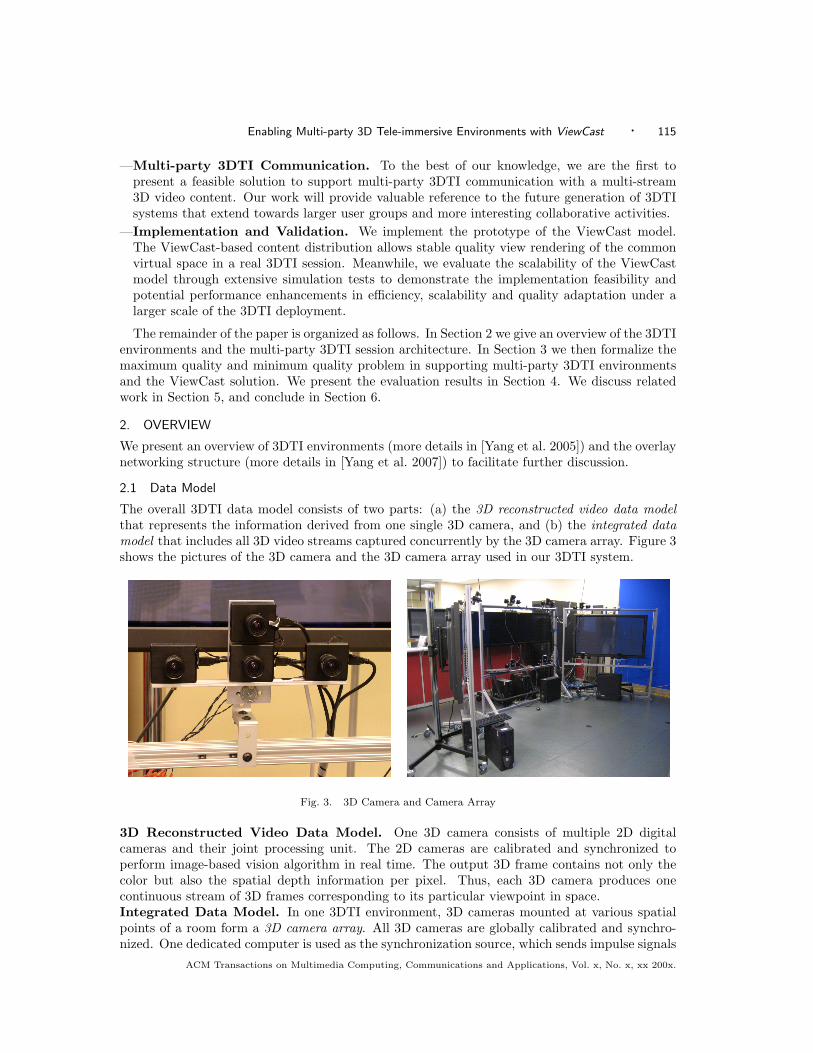
The overall 3DTI data model consists of two parts: (a) the 3D reconstructed video data modelthat represents the information derived from one single 3D camera, and (b) the integrated datamodel that includes all 3D video streams captured concurrently by the 3D camera array. Figure 3shows the pictures of the 3D camera and the 3D camera array used in our 3DTI system.
Fig. 3. 3D Camera and Camera Array
3D Reconstructed Video Data Model. One 3D camera consists of multiple 2D digitalcameras and their joint processing unit. The 2D cameras are calibrated and synchronized toperform image-based vision algorithm in real time. The output 3D frame contains not only thecolor but also the spatial depth information per pixel. Thus, each 3D camera produces onecontinuous stream of 3D frames corresponding to its particular viewpoint in space.Integrated Data Model. In one 3DTI environment, 3D cameras mounted at various spatialpoints of a room form a 3D camera array. All 3D cameras are globally calibrated and synchro-nized. One dedicated computer is used as the synchronization source, which sends impulse signals
ACM Transactions on Multimedia Computing, Communications and Applications, Vol. x, No. x, xx 200x.
116 · Z. Yang et al.
to the external trigger of all cameras via the general purpose input/output (GPIO) pins on thecamera board. The average time from when the trigger register is written to the start of theintegration of the image frame is approximately 56 µs, which allows for very high synchroniza-tion accuracy (ignoring the signal propagation delay). Therefore, the set of 3D frames bearingthe same timestamp, denoted as one macro-frame, constitutes a comprehensive panorama-likerepresentation of the physical scene. Note that, except for calibration and synchronization, each3D camera is an independent unit in terms of the visual content.1
2.2 View Model
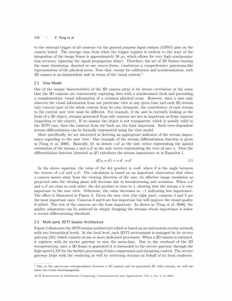
One of the unique characteristics of the 3D camera array is its stream correlation in the sensethat the 3D cameras are concurrently capturing data with a synchronized clock and presentinga complementary visual information of a common physical scene. However, since a user onlyobserves the visual information from one particular view at any given time and each 3D streamonly conveys part of the whole content from its own viewpoint, the contribution of each streamto the current user view must be different. For example, if the user is currently looking at thefront of a 3D object, streams generated from side cameras are not as important as front cameras(regarding to the object). If we assume the object is not transparent, which is usually valid inthe 3DTI case, then the cameras from the back are the least important. Such view-dependentstream differentiation can be formally represented using the view model.
More specifically, we are interested in deriving an appropriate indicator of the stream impor-tance regarding to the user view. One example of the stream differentiation function is givenin [Yang et al. 2006]. Basically, let us denote s.~w as the unit vector representing the spatialorientation of the stream s and u.~w as the unit vector representing the view of user u. Then thedifferentiation function (denoted as df) calculates the stream importance as in Equation 1.
df(s, u.~w) = s.~w · u.~w (1)
In the above equation, the value of the dot product is cosθ, where θ is the angle betweenthe vectors of s.~w and u.~w. The calculation is based on an important observation that whena camera moves away from the viewing direction of the user, its effective image resolution asprojected onto the viewing plane will decrease due to foreshortening and occlusion. When s.~wand u.~w are close to each other, the dot product is close to 1, showing that the stream s is veryimportant to the user view. Otherwise, the value decreases to −1 indicating less importance.The effect is illustrated in Figure 4. Given the user view (the right part), cameras 4 and 5 arethe most important ones. Cameras 3 and 6 are less important but will improve the visual qualityif added. The rest of the cameras are the least important. As shown in [Yang et al. 2006], thequality adaptation can be achieved by simply dropping the streams whose importance is belowa certain differentiating threshold.
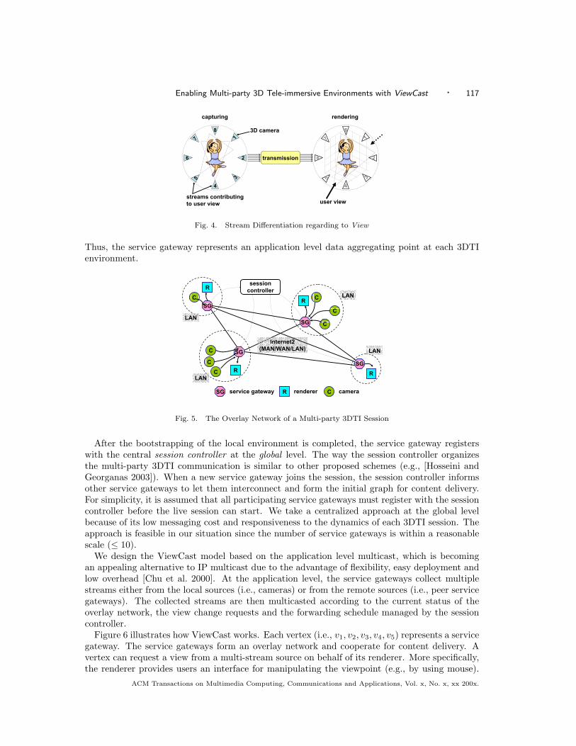
2.3 Multi-party 3DTI Session Architecture
Figure 5 illustrates the 3DTI session architecture which is based on an end-system overlay networkwith two hierarchical levels. At the local level, each 3DTI environment is managed by its servicegateway (SG) which consists of one or more dedicated processors. When a 3D camera is initiated,it registers with its service gateway to save the meta-data. Due to the overhead of the 3Dreconstruction, once a 3D frame is generated it is forwarded to the service gateway through thehigh-speed LAN for the further processing of data compression and streaming control. The servicegateway helps with the rendering as well by retrieving streams on behalf of its local renderers.
1 Due to the one-to-one correspondence between a 3D camera and its generated 3D video stream, we will usethese two terms interchangeably.
ACM Transactions on Multimedia Computing, Communications and Applications, Vol. x, No. x, xx 200x.
Enabling Multi-party 3D Tele-immersive Environments with ViewCast · 117
capturing
1
5
7
3
8
4
6 2
3D camera
transmission
1
5
7
3
8
4
6 2
rendering
user viewstreams contributingto user view
Fig. 4. Stream Differentiation regarding to View
Thus, the service gateway represents an application level data aggregating point at each 3DTIenvironment.
C
CC
SG
R
C
C
C
SG
R
SGR
CSG
R
R CSG service gateway renderer camera
sessioncontroller
LAN
LAN
LAN
LANInternet2
(MAN/WAN/LAN)
Fig. 5. The Overlay Network of a Multi-party 3DTI Session
After the bootstrapping of the local environment is completed, the service gateway registerswith the central session controller at the global level. The way the session controller organizesthe multi-party 3DTI communication is similar to other proposed schemes (e.g., [Hosseini andGeorganas 2003]). When a new service gateway joins the session, the session controller informsother service gateways to let them interconnect and form the initial graph for content delivery.For simplicity, it is assumed that all participating service gateways must register with the sessioncontroller before the live session can start. We take a centralized approach at the global levelbecause of its low messaging cost and responsiveness to the dynamics of each 3DTI session. Theapproach is feasible in our situation since the number of service gateways is within a reasonablescale (≤ 10).
We design the ViewCast model based on the application level multicast, which is becomingan appealing alternative to IP multicast due to the advantage of flexibility, easy deployment andlow overhead [Chu et al. 2000]. At the application level, the service gateways collect multiplestreams either from the local sources (i.e., cameras) or from the remote sources (i.e., peer servicegateways). The collected streams are then multicasted according to the current status of theoverlay network, the view change requests and the forwarding schedule managed by the sessioncontroller.
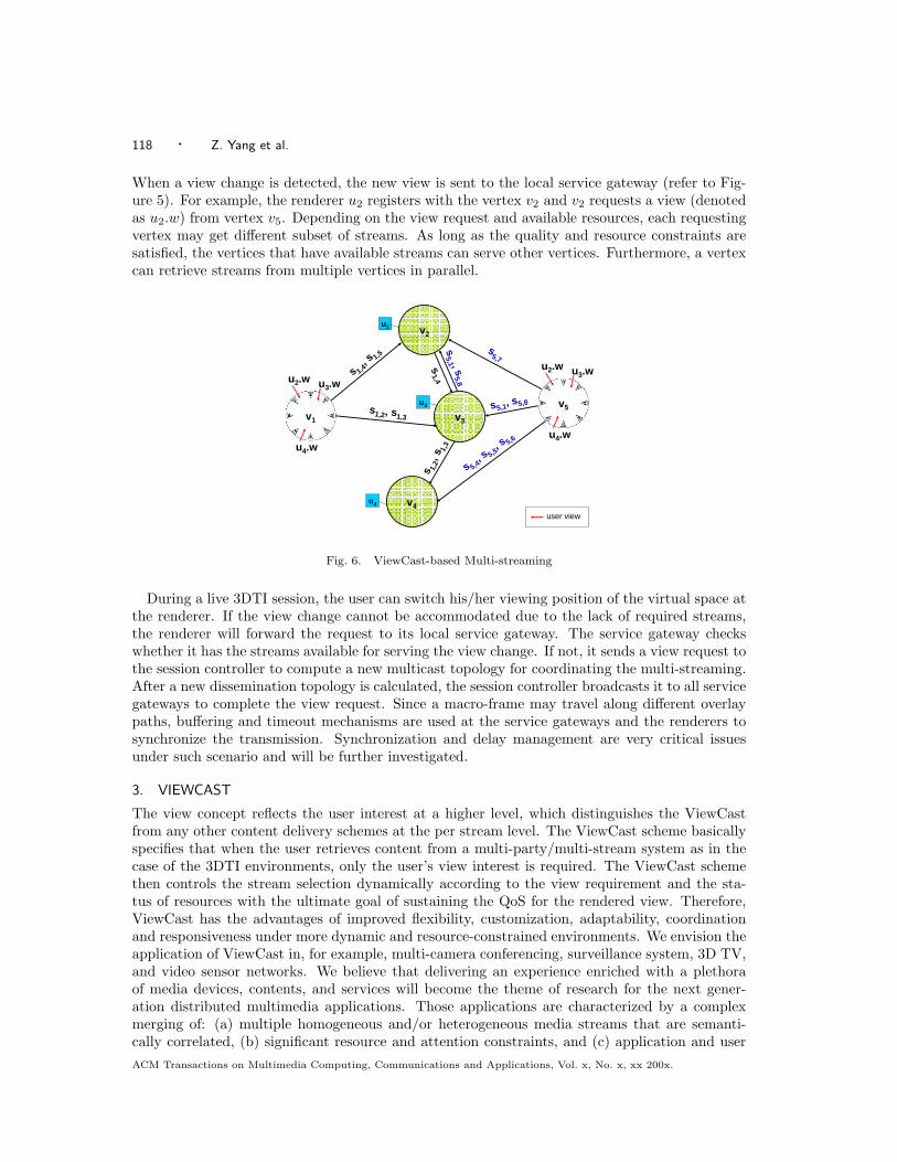
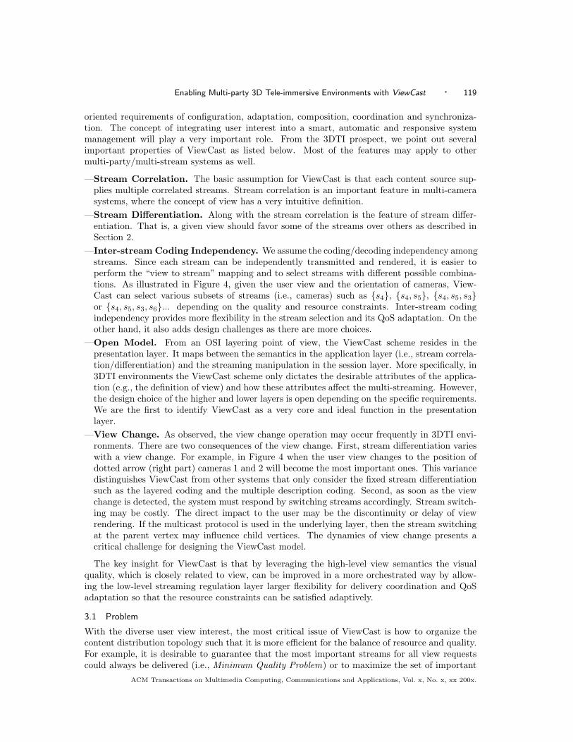
Figure 6 illustrates how ViewCast works. Each vertex (i.e., v1, v2, v3, v4, v5) represents a servicegateway. The service gateways form an overlay network and cooperate for content delivery. Avertex can request a view from a multi-stream source on behalf of its renderer. More specifically,the renderer provides users an interface for manipulating the viewpoint (e.g., by using mouse).
ACM Transactions on Multimedia Computing, Communications and Applications, Vol. x, No. x, xx 200x.
118 · Z. Yang et al.
When a view change is detected, the new view is sent to the local service gateway (refer to Fig-ure 5). For example, the renderer u2 registers with the vertex v2 and v2 requests a view (denotedas u2.w) from vertex v5. Depending on the view request and available resources, each requestingvertex may get different subset of streams. As long as the quality and resource constraints aresatisfied, the vertices that have available streams can serve other vertices. Furthermore, a vertexcan retrieve streams from multiple vertices in parallel.
v2
v3
v4
v1
v5
s 1,4, s 1,5
s1,4
s1,2, s1,3s 1,
2, s 1,
3
u2.w u3.w
u4.w
s5,1, s5,8
s5,7
s 5,4, s 5,5
, s 5,6
user view
u2.w u3.w
u4.ws
5,1 , s5,8
u2
u3
u4
Fig. 6. ViewCast-based Multi-streaming
During a live 3DTI session, the user can switch his/her viewing position of the virtual space atthe renderer. If the view change cannot be accommodated due to the lack of required streams,the renderer will forward the request to its local service gateway. The service gateway checkswhether it has the streams available for serving the view change. If not, it sends a view request tothe session controller to compute a new multicast topology for coordinating the multi-streaming.After a new dissemination topology is calculated, the session controller broadcasts it to all servicegateways to complete the view request. Since a macro-frame may travel along different overlaypaths, buffering and timeout mechanisms are used at the service gateways and the renderers tosynchronize the transmission. Synchronization and delay management are very critical issuesunder such scenario and will be further investigated.
3. VIEWCAST
The view concept reflects the user interest at a higher level, which distinguishes the ViewCastfrom any other content delivery schemes at the per stream level. The ViewCast scheme basicallyspecifies that when the user retrieves content from a multi-party/multi-stream system as in thecase of the 3DTI environments, only the user’s view interest is required. The ViewCast schemethen controls the stream selection dynamically according to the view requirement and the sta-tus of resources with the ultimate goal of sustaining the QoS for the rendered view. Therefore,ViewCast has the advantages of improved flexibility, customization, adaptability, coordinationand responsiveness under more dynamic and resource-constrained environments. We envision theapplication of ViewCast in, for example, multi-camera conferencing, surveillance system, 3D TV,and video sensor networks. We believe that delivering an experience enriched with a plethoraof media devices, contents, and services will become the theme of research for the next gener-ation distributed multimedia applications. Those applications are characterized by a complexmerging of: (a) multiple homogeneous and/or heterogeneous media streams that are semanti-cally correlated, (b) significant resource and attention constraints, and (c) application and userACM Transactions on Multimedia Computing, Communications and Applications, Vol. x, No. x, xx 200x.
Enabling Multi-party 3D Tele-immersive Environments with ViewCast · 119
oriented requirements of configuration, adaptation, composition, coordination and synchroniza-tion. The concept of integrating user interest into a smart, automatic and responsive systemmanagement will play a very important role. From the 3DTI prospect, we point out severalimportant properties of ViewCast as listed below. Most of the features may apply to othermulti-party/multi-stream systems as well.
—Stream Correlation. The basic assumption for ViewCast is that each content source sup-plies multiple correlated streams. Stream correlation is an important feature in multi-camerasystems, where the concept of view has a very intuitive definition.
—Stream Differentiation. Along with the stream correlation is the feature of stream differ-entiation. That is, a given view should favor some of the streams over others as described inSection 2.
—Inter-stream Coding Independency. We assume the coding/decoding independency amongstreams. Since each stream can be independently transmitted and rendered, it is easier toperform the “view to stream” mapping and to select streams with different possible combina-tions. As illustrated in Figure 4, given the user view and the orientation of cameras, View-Cast can select various subsets of streams (i.e., cameras) such as {s4}, {s4, s5}, {s4, s5, s3}or {s4, s5, s3, s6}... depending on the quality and resource constraints. Inter-stream codingindependency provides more flexibility in the stream selection and its QoS adaptation. On theother hand, it also adds design challenges as there are more choices.
—Open Model. From an OSI layering point of view, the ViewCast scheme resides in thepresentation layer. It maps between the semantics in the application layer (i.e., stream correla-tion/differentiation) and the streaming manipulation in the session layer. More specifically, in3DTI environments the ViewCast scheme only dictates the desirable attributes of the applica-tion (e.g., the definition of view) and how these attributes affect the multi-streaming. However,the design choice of the higher and lower layers is open depending on the specific requirements.We are the first to identify ViewCast as a very core and ideal function in the presentationlayer.
—View Change. As observed, the view change operation may occur frequently in 3DTI envi-ronments. There are two consequences of the view change. First, stream differentiation varieswith a view change. For example, in Figure 4 when the user view changes to the position ofdotted arrow (right part) cameras 1 and 2 will become the most important ones. This variancedistinguishes ViewCast from other systems that only consider the fixed stream differentiationsuch as the layered coding and the multiple description coding. Second, as soon as the viewchange is detected, the system must respond by switching streams accordingly. Stream switch-ing may be costly. The direct impact to the user may be the discontinuity or delay of viewrendering. If the multicast protocol is used in the underlying layer, then the stream switchingat the parent vertex may influence child vertices. The dynamics of view change presents acritical challenge for designing the ViewCast model.
The key insight for ViewCast is that by leveraging the high-level view semantics the visualquality, which is closely related to view, can be improved in a more orchestrated way by allow-ing the low-level streaming regulation layer larger flexibility for delivery coordination and QoSadaptation so that the resource constraints can be satisfied adaptively.
3.1 Problem
With the diverse user view interest, the most critical issue of ViewCast is how to organize thecontent distribution topology such that it is more efficient for the balance of resource and quality.For example, it is desirable to guarantee that the most important streams for all view requestscould always be delivered (i.e., Minimum Quality Problem) or to maximize the set of important
ACM Transactions on Multimedia Computing, Communications and Applications, Vol. x, No. x, xx 200x.
120 · Z. Yang et al.
streams for all view requests (i.e., Maximum Quality Problem). However, those problems aregenerally NP-hard under various system constraints including the bandwidth constraints, therelay constraints, and the delay constraints (more details in [Yang et al. 2007]). If we furtherconsider the dynamics of the user view interests, those problems will become more complicated.
Note that, an ideal criterion of stream importance should be based on the rendering quality.However, in 3DTI environments the rendering quality of particular view depends on the set ofstreams received. Since it is quite complicated to derive an exact form of the quality functionwith a given set of streams, a simple linear approach is taken to evaluate the relevance of a setstreams S′ to a view w as shown in Equation (2),
relv(S′, w) =∑s∈S′
df(s, w) (2)
where df denotes the differentiation function which gives the relevance of a stream regardingto a given user view. Depending on a specific application, the definition of the differentiationfunction could be different. In the case of 3DTI environments, the differentiation function isgiven in Equation 1. The above function of relevance is what we use as the basis to formulateand investigate the problems as we mention earlier. For example, the minimum quality problemcan be formulated as below.
Minimum Quality Problem1. to satisfy: ∀vi ∈ V, relv(Ri, vi.w) ≥ ∆2. subject to bandwidth, delay, and system availability constraints
where ∆ is a given lowest bound, Ri represents the set of streams that node vi is currentlyreceiving, and vi.w represents the view of vi. Although in the rest of the discussion we keepusing the term quality, it should be clear that the quality of a set of streams refers to the overallrelevance instead of the final rendering quality.
3.2 Solution
We have two major designing goals for the solution of ViewCast.
—Minimum quality guarantee. Each vertex should receive a minimum set of streams to havesome rendering quality guarantee of every other vertex inside its view. For 3DTI environments,it implies the consistent presence of all participants in the virtual space, which is critical forthe collaborative work.
—View change resilience. When a vertex changes its view, the impact on other affectedvertices should be minimized for the continuity of group interaction.
3.2.1 Minimum Quality Guarantee
Because the minimum quality problem is NP-hard, we propose heuristics using the approachbased on priority [Yang et al. 2006] and preemption [Yang et al. 2007] with the following steps.Step 1. Given a view request v.w, the importance of the stream is calculated using the differen-tiation function df(s, v.w).Step 2. The streams are selected if the df value is above a certain threshold. For example, inour 3DTI environment we choose the streams with df(s, v.w) ≥ 0, reflecting a 180 ◦ total viewrange.Step 3. The selected streams are further differentiated into several priority groups accordingto their importance. We define the set of priorities P as {p1, p2, ..., pk}, where p is in ascendingorder, i.e., pi < pi+1 for i = 1 to k − 1. We assign priorities to the selected streams accordingto the differentiation function. That is, we sort the selected streams according to the value ofthe differentiation function. The stream with the largest value of the differentiation function isassigned the highest priority pk, the stream with the second largest value is assigned the theACM Transactions on Multimedia Computing, Communications and Applications, Vol. x, No. x, xx 200x.
Enabling Multi-party 3D Tele-immersive Environments with ViewCast · 121
priority pk−1, and so forth. The result is that each priority group (with priority pi) typicallycontains one stream from each site. The choice of the parameter k depends on the number ofstreams originating from each vertex. In 3DTI environments each vertex has around 8 streams.The stream selection in Step 2 produces a subset of 3 to 4 streams. Therefore, we set k to be 4.Step 4. As mentioned earlier, the inbound (and outbound) bandwidth resource is divided intobins with each bin hosting one stream. Suppose it is needed to forward a stream s from thevertex vi to the vertex vj . If both vertices have available bins, it is straightforward to establishthe streaming. Otherwise, the bin of lower priority stream can be preempted. For example, if thestream s has p4 priority based on the view, it can take the outbound (or inbound) bin occupiedby the stream of a lower priority (i.e., p1, p2, p3) in either vi or vj respectively. When thepreemption is needed, the bin of the lowest priority stream will be taken first. The bin allocationof the selected streams is performed in the descending order of priority and terminated whenthe preemption is not possible.2 Note that the broken links will be repaired by a fix victim()routine described in the next section.
The preemption mechanism is important in the resource-constrained 3DTI environments. Sincebandwidth is such a sparse resource, prioritization-based preemption is a key to guarantee efficientutilization of the resource in times of contention. Further, preemption is not “intrusive” (in thesense of visual quality disruption) due to the 3D data representation. All streams are aggregatedand rendered into a single 3D representation of human body, which is very different from theconventional 2D video systems where losing a stream means losing a scene (e.g., the windowshowing that stream). Here when the user is observing the scene from the front view, for example,it will not be as visually noticeable if some stream from the side view is preempted. The 3Dpixel cloud of the participant is still being rendered, only that some of the less important points(in terms of view) are absent. The released resource can then be used to serve higher-prioritystreams which contribute more to the overall visual quality.
3.2.2 View Change Resilience
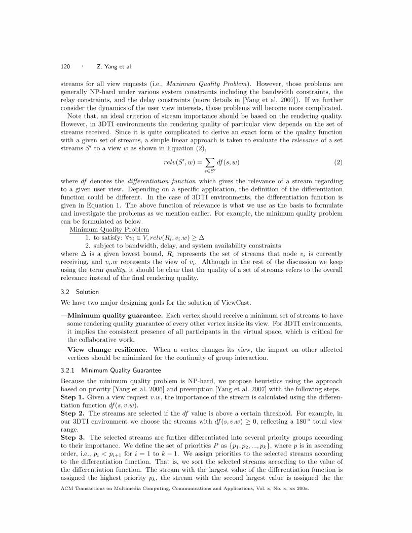
The negative impact of the view change is illustrated in Figure 7. In the figure, the vertex v3 andv4 have similar views and v4 is streaming s2 and s3 from v3. When the vertex v3 changes its view,streams needed by v4 may temporarily become unavailable. In such a case, v4 has victims (i.e.,broken streams). The impact will grow as the number of dependent vertices increases. The viewchange operation is a frequent phenomenon in 3DTI environment and may cause large overheadif not treated properly. Note that, the streaming preemption as introduced in Section 3.2.1 mayalso cause an involuntary termination of streaming in a way similar to the view change.
In a related domain, there are previous solutions dealing with a multicast member join/leavewhich rely on the concepts of soft leave [Hosseini and Georganas 2003], buffering [Cui and Nahrst-edt 2003] and rearrangement [Bauer and Varma 1997; Sriram et al. 1999]. Soft leave requires thechanging vertex to continuously serve old streams until affected vertices have found replacement.Although doable, under multi-stream scenario it would incur longer delay. Buffering let theintermediate vertices continue streaming from cache to absorb the propagation of quality degra-dation. However, it is not a feasible approach for live communication. Rearrangement involveslarge overhead which requires the multicast content delivery schedule to be relatively stable toamortize the cost.
As we observe, none of these solutions would directly fit in the case of 3DTI environments.Instead, we apply the strategy of dependency balancing to improve the resilience of view changetolerance. There are three basic techniques in dependency balancing: (1) source balancing, (2)
2 Currently, ViewCast is operated at the per stream granularity. When there is not enough resource to transmit astream at its full content, the streaming will be dropped. However, it is an interesting problem to explore whethera quantitative improvement could be achieved at finer granularity (e.g., to transmit a stream with different rates).
ACM Transactions on Multimedia Computing, Communications and Applications, Vol. x, No. x, xx 200x.
122 · Z. Yang et al.
V2
V3
V4
V1
u2.w u3.w
u4.w
s 4, s 5
s2, s3
s 2, s 3
u2
u3
s4
u4
V2
V3
V4
V1
u2.w
u4.w
s 4, s 5
s 2, s 3
u2
u3s
4
u4
s7, s8
u3.w
victim
(a) Before View Change (b) After View Change
Fig. 7. Effect of View Change
VC - Approaches
Dependency balancing1. Source – As long as delay requirement is
met, try to stream from more sources.
va vb
sj,1 sj,2
vc
va vb
sj,1
vc
sj,2
better
sj,1 sj,2 sj,1 sj,2 sj,1 sj,2 sj,1 sj,2
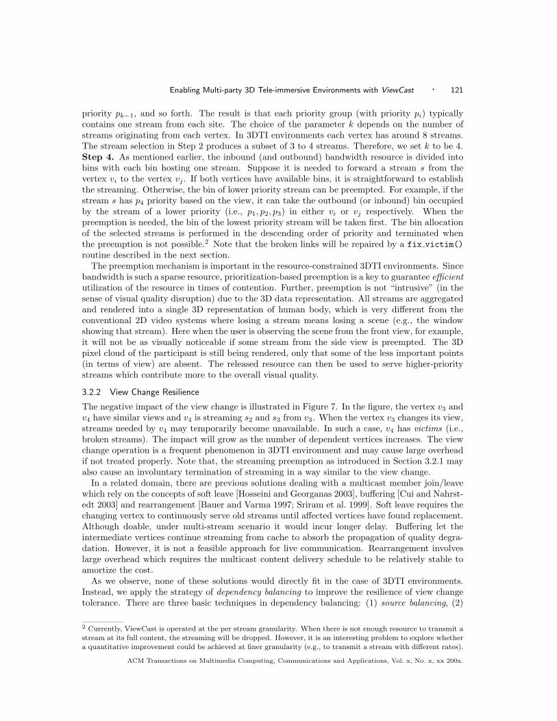
Fig. 8. Source Balancing in ViewCast
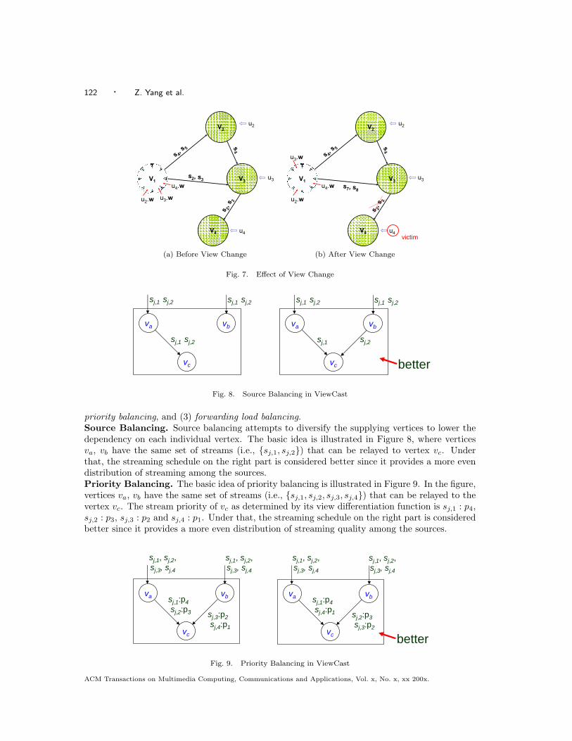
priority balancing, and (3) forwarding load balancing.Source Balancing. Source balancing attempts to diversify the supplying vertices to lower thedependency on each individual vertex. The basic idea is illustrated in Figure 8, where verticesva, vb have the same set of streams (i.e., {sj,1, sj,2}) that can be relayed to vertex vc. Underthat, the streaming schedule on the right part is considered better since it provides a more evendistribution of streaming among the sources.Priority Balancing. The basic idea of priority balancing is illustrated in Figure 9. In the figure,vertices va, vb have the same set of streams (i.e., {sj,1, sj,2, sj,3, sj,4}) that can be relayed to thevertex vc. The stream priority of vc as determined by its view differentiation function is sj,1 : p4,sj,2 : p3, sj,3 : p2 and sj,4 : p1. Under that, the streaming schedule on the right part is consideredbetter since it provides a more even distribution of streaming quality among the sources.
VC - Approaches
Dependency balancing2. Priority – Distributed streams among
sources in uniformity of priority.
va vbsj,1:p4 sj,2:p3
vc
sj,3:p2 sj,4:p1
va vbsj,1:p4 sj,4:p1
vc
sj,2:p3 sj,3:p2
better
sj,1, sj,2,sj,3, sj,4
sj,1, sj,2,sj,3, sj,4
sj,1, sj,2,sj,3, sj,4
sj,1, sj,2,sj,3, sj,4
Fig. 9. Priority Balancing in ViewCast
ACM Transactions on Multimedia Computing, Communications and Applications, Vol. x, No. x, xx 200x.
Enabling Multi-party 3D Tele-immersive Environments with ViewCast · 123
vc
va
vb
vc
va
vb
better
total forwarding load
TFa = 4
TFb = 0
forwarding load to specific vertex
TFa-c = 0
TFb-c = 0
sj,1, sj,2,sj,3, sj,4
sj,1, sj,2,sj,3, sj,4
sj,1, sj,2,sj,3, sj,4
sj,1, sj,2,sj,3, sj,4
Fig. 10. Forwarding Load Balancing in ViewCast
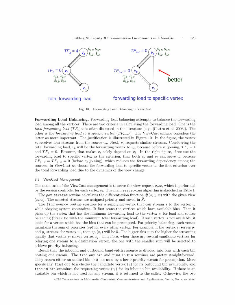
Forwarding Load Balancing. Forwarding load balancing attempts to balance the forwardingload among all the vertices. There are two criteria in calculating the forwarding load. One is thetotal forwarding load (TFv)as is often discussed in the literature (e.g., [Castro et al. 2003]). Theother is the forwarding load to a specific vertex (TFv−v′). The ViewCast scheme considers thelatter as more important. The justification is illustrated in Figure 10. In the figure, the vertexvb receives four streams from the source va. Next, vc requests similar streams. Considering thetotal forwarding load, vb will be the forwarding vertex to vc, because before vc joining, TFa = 4and TFb = 0. However, that makes vc solely depend on vb. In the right figure, if we use theforwarding load to specific vertex as the criterion, then both va and vb can serve vc becauseTFa−c = TFb−c = 0 (before vc joining), which reduces the forwarding dependency among thesources. In ViewCast we choose the forwarding load to specific vertex as the first criterion overthe total forwarding load due to the dynamics of the view change.
3.3 ViewCast Management
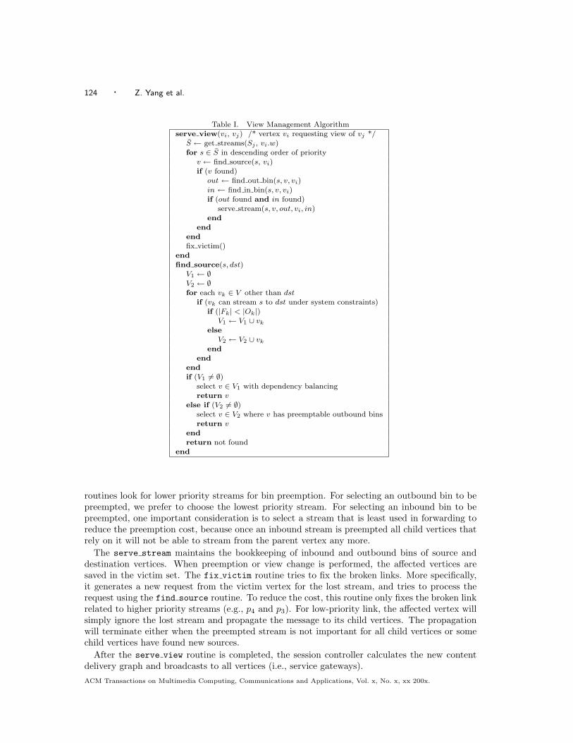
The main task of the ViewCast management is to serve the view request vi.w, which is performedby the session controller for each vertex vi. The main serve view algorithm is sketched in Table I.
The get streams routine calculates the differentiation function df(s, vi.w) with the given view(vi.w). The selected streams are assigned priority and saved in S.
The find source routine searches for a supplying vertex that can stream s to the vertex vi
while obeying system constraints. It first scans the vertices which have available bins. Then itpicks up the vertex that has the minimum forwarding load to the vertex vi for load and sourcebalancing (break tie with the minimum total forwarding load). If such vertex is not available, itlooks for a vertex which has the bins that can be preempted. For priority balancing, each vertexmaintains the sum of priorities (sp) for every other vertex. For example, if the vertex vi serves p3
and p2 streams for vertex vj , then spi(vj) will be 5. The bigger this sum the higher the streamingquality that vertex vi serves vertex vj . Therefore, when there are several candidate vertices forrelaying one stream to a destination vertex, the one with the smaller sum will be selected toachieve priority balancing.
Recall that the inbound and outbound bandwidth resource is divided into bins with each binhosting one stream. The find out bin and find in bin routines are pretty straightforward.They return either an unused bin or a bin used by a lower priority stream for preemption. Morespecifically, find out bin checks the candidate vertex (v) for its outbound bin availability, andfind in bin examines the requesting vertex (vi) for its inbound bin availability. If there is anavailable bin which is not used for any stream, it is returned to the caller. Otherwise, the two
ACM Transactions on Multimedia Computing, Communications and Applications, Vol. x, No. x, xx 200x.
124 · Z. Yang et al.
Table I. View Management Algorithmserve view(vi, vj) /* vertex vi requesting view of vj */
S ← get streams(Sj , vi.w)for s ∈ S in descending order of priority
v ← find source(s, vi)if (v found)
out ← find out bin(s, v, vi)in ← find in bin(s, v, vi)if (out found and in found)
serve stream(s, v, out, vi, in)end
endendfix victim()
endfind source(s, dst)
V1 ← ∅V2 ← ∅for each vk ∈ V other than dst
if (vk can stream s to dst under system constraints)if (|Fk| < |Ok|)
V1 ← V1 ∪ vk
elseV2 ← V2 ∪ vk
endend
endif (V1 6= ∅)
select v ∈ V1 with dependency balancingreturn v
else if (V2 6= ∅)select v ∈ V2 where v has preemptable outbound binsreturn v
endreturn not found
end
routines look for lower priority streams for bin preemption. For selecting an outbound bin to bepreempted, we prefer to choose the lowest priority stream. For selecting an inbound bin to bepreempted, one important consideration is to select a stream that is least used in forwarding toreduce the preemption cost, because once an inbound stream is preempted all child vertices thatrely on it will not be able to stream from the parent vertex any more.
The serve stream maintains the bookkeeping of inbound and outbound bins of source anddestination vertices. When preemption or view change is performed, the affected vertices aresaved in the victim set. The fix victim routine tries to fix the broken links. More specifically,it generates a new request from the victim vertex for the lost stream, and tries to process therequest using the find source routine. To reduce the cost, this routine only fixes the broken linkrelated to higher priority streams (e.g., p4 and p3). For low-priority link, the affected vertex willsimply ignore the lost stream and propagate the message to its child vertices. The propagationwill terminate either when the preempted stream is not important for all child vertices or somechild vertices have found new sources.
After the serve view routine is completed, the session controller calculates the new contentdelivery graph and broadcasts to all vertices (i.e., service gateways).ACM Transactions on Multimedia Computing, Communications and Applications, Vol. x, No. x, xx 200x.
Enabling Multi-party 3D Tele-immersive Environments with ViewCast · 125
4. EVALUATION
For evaluation, we have conducted both simulation and Internet experiments. The simulationexperiments help us to analyze the scaling property of ViewCast with larger session sizes. Mean-while, the Internet experiments provide us with a more practical sense of performance under thereal environment with real users. In the rest of this section, we present the schemes, metrics, andresults of our simulation and Internet experiments.
4.1 Simulation Evaluation
For a more extensive evaluation, we simulate the ViewCast model under the multi-party 3DTIscenario with a message-driven simulator written in C++ (on Windows and Linux operatingsystems). More details of the simulation setup are provided in the following sections.
4.1.1 Experiment Setup
The simulator first generates the graph of an application-level overlay network. We use themesh topology for the overlay network, where the connectivity between vertices follows the uni-form distribution. The total number of vertices, defined as the session size, ranges from 5 to 10.Since the human attention space is intrinsically limited, we do not expect the size of a sessionto be larger than ten sites. The total number of edges is determined by connectivity ratio (CR)which is the ratio of edges compared with the corresponding complete directed graph. For exam-ple, a directed graph of 8 vertices will have 42 edges, if the connectivity ratio is set to 75% (i.e.,56× 75%). We choose the connectivity ratio from 25% to 100%.
In the experiment, each vertex has 8 original streams which are evenly distributed in the 360 ◦
space. For any view request to a vertex, at most 4 of its original streams are selected for an optimalcoverage of 180 ◦. To determine the range of inward/outward degree bound, in the maximal caseof 10 vertices each vertex requires at least an in-degree of 36 to get the optimal coverage fromevery other vertex and an out-degree of 8 so that all its streams may be accessible for serving anyview. The estimation has not considered relaying overhead. For simplicity, we set the in-degreebound to be the same as the out-degree bound (later we evaluate the heterogeneity in the Internetexperiments). Recall that the in-degree and out-degree of a vertex are in the number of streams(Section 3). We set the degree bound (DegB) to be 12 (to simulate a small-capacity network)or 36 (large-capacity network) respectively. These numbers are chosen according to our Internetmeasurements.
During the simulated 3DTI session, each vertex sends the view change request to the centralsession controller. The view change interval follows the normal distribution with a mean of60 seconds. The total running time of one simulation experiment is 200 minutes. We use twopatterns of the view change: random walk and Zipf. In the random walk pattern, each vertex addsa view change degree to its current view. The view change degree follows the normal distributionwith a standard deviation of 20 ◦. We choose the Zipf distribution for the pattern of view changebecause it is recognized as the common selection pattern for multimedia data [Sripanidkulchaiet al. 2004]. The view is changed according to a Zipf distribution of 10 pre-selected view degrees(i.e., n = 10). The Zipf distribution is actually the power-law distribution in discrete form. Inour 3DTI simulation, it dictates that the ith most popular view degree has the access frequencyin proportion to ω/iα, where α is a constant (we choose α = 1.0) and ω is determined by n.
The propagation delay along each edge follows the normal distribution with a mean of 50 ms.We assume each stream has the same bandwidth. The simulation parameters are summarized inTable II.
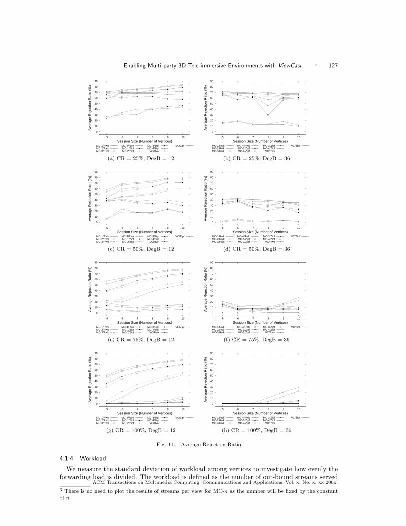
4.1.2 Rejection Ratio
We measure the rejection ratio of each view change request. Recall that in ViewCast, the viewchange request is served with relevant streams in descending order of importance and the request
ACM Transactions on Multimedia Computing, Communications and Applications, Vol. x, No. x, xx 200x.
126 · Z. Yang et al.
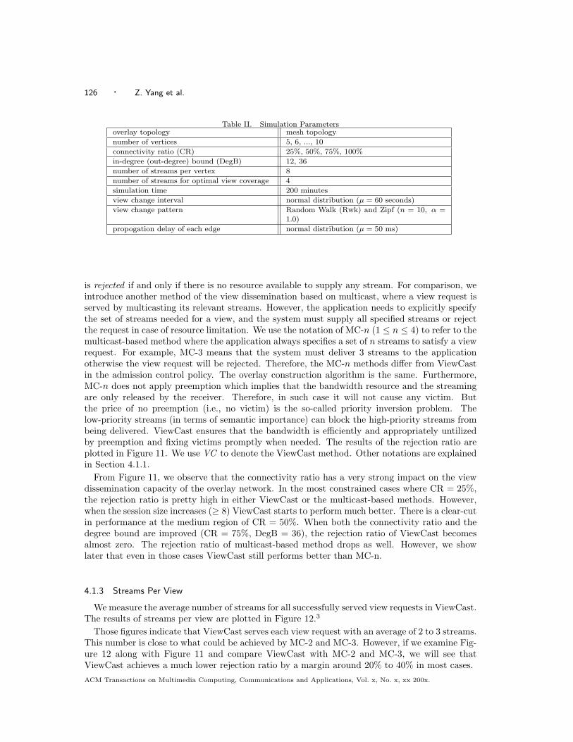
Table II. Simulation Parametersoverlay topology mesh topology
number of vertices 5, 6, ..., 10
connectivity ratio (CR) 25%, 50%, 75%, 100%
in-degree (out-degree) bound (DegB) 12, 36
number of streams per vertex 8
number of streams for optimal view coverage 4
simulation time 200 minutes
view change interval normal distribution (µ = 60 seconds)
view change pattern Random Walk (Rwk) and Zipf (n = 10, α =1.0)
propogation delay of each edge normal distribution (µ = 50 ms)
is rejected if and only if there is no resource available to supply any stream. For comparison, weintroduce another method of the view dissemination based on multicast, where a view request isserved by multicasting its relevant streams. However, the application needs to explicitly specifythe set of streams needed for a view, and the system must supply all specified streams or rejectthe request in case of resource limitation. We use the notation of MC-n (1 ≤ n ≤ 4) to refer to themulticast-based method where the application always specifies a set of n streams to satisfy a viewrequest. For example, MC-3 means that the system must deliver 3 streams to the applicationotherwise the view request will be rejected. Therefore, the MC-n methods differ from ViewCastin the admission control policy. The overlay construction algorithm is the same. Furthermore,MC-n does not apply preemption which implies that the bandwidth resource and the streamingare only released by the receiver. Therefore, in such case it will not cause any victim. Butthe price of no preemption (i.e., no victim) is the so-called priority inversion problem. Thelow-priority streams (in terms of semantic importance) can block the high-priority streams frombeing delivered. ViewCast ensures that the bandwidth is efficiently and appropriately untilizedby preemption and fixing victims promptly when needed. The results of the rejection ratio areplotted in Figure 11. We use VC to denote the ViewCast method. Other notations are explainedin Section 4.1.1.
From Figure 11, we observe that the connectivity ratio has a very strong impact on the viewdissemination capacity of the overlay network. In the most constrained cases where CR = 25%,the rejection ratio is pretty high in either ViewCast or the multicast-based methods. However,when the session size increases (≥ 8) ViewCast starts to perform much better. There is a clear-cutin performance at the medium region of CR = 50%. When both the connectivity ratio and thedegree bound are improved (CR = 75%, DegB = 36), the rejection ratio of ViewCast becomesalmost zero. The rejection ratio of multicast-based method drops as well. However, we showlater that even in those cases ViewCast still performs better than MC-n.
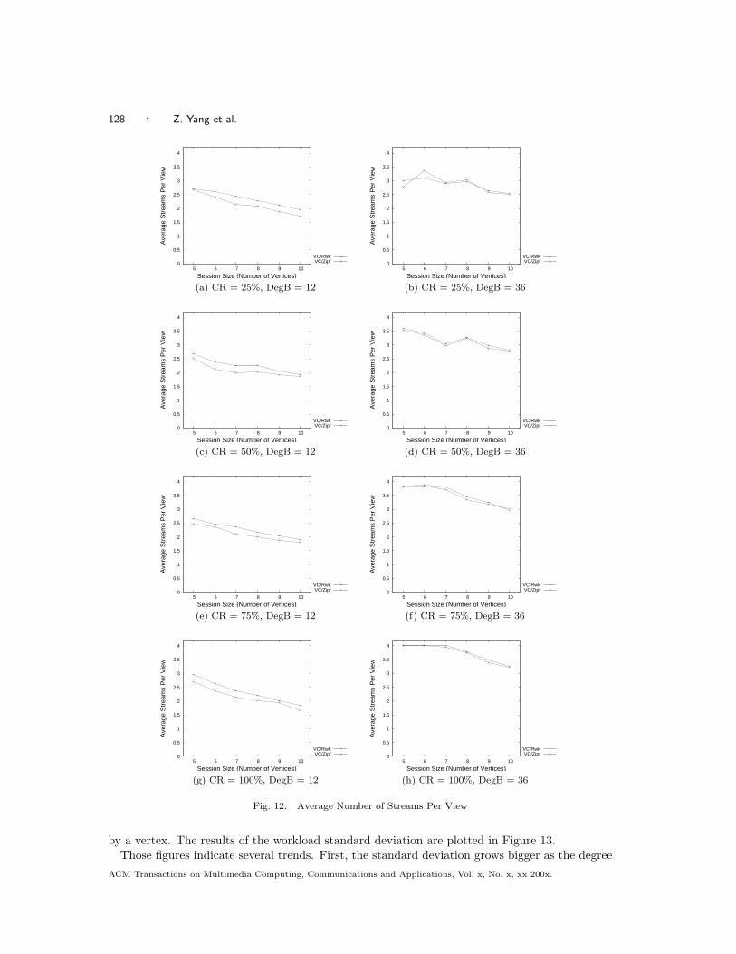
4.1.3 Streams Per View
We measure the average number of streams for all successfully served view requests in ViewCast.The results of streams per view are plotted in Figure 12.3
Those figures indicate that ViewCast serves each view request with an average of 2 to 3 streams.This number is close to what could be achieved by MC-2 and MC-3. However, if we examine Fig-ure 12 along with Figure 11 and compare ViewCast with MC-2 and MC-3, we will see thatViewCast achieves a much lower rejection ratio by a margin around 20% to 40% in most cases.ACM Transactions on Multimedia Computing, Communications and Applications, Vol. x, No. x, xx 200x.
Enabling Multi-party 3D Tele-immersive Environments with ViewCast · 127
0
10
20
30
40
50
60
70
80
90
5 6 7 8 9 10
Ave
rage
Rej
ectio
n R
atio
(%
)
Session Size (Number of Vertices)MC-1/RwkMC-2/RwkMC-3/Rwk
MC-4/RwkMC-1/ZipfMC-2/Zipf
MC-3/ZipfMC-4/Zipf
VC/Rwk
VC/Zipf
0
10
20
30
40
50
60
70
80
90
5 6 7 8 9 10
Ave
rage
Rej
ectio
n R
atio
(%
)
Session Size (Number of Vertices)MC-1/RwkMC-2/RwkMC-3/Rwk
MC-4/RwkMC-1/ZipfMC-2/Zipf
MC-3/ZipfMC-4/Zipf
VC/Rwk
VC/Zipf
(a) CR = 25%, DegB = 12 (b) CR = 25%, DegB = 36
0
10
20
30
40
50
60
70
80
90
5 6 7 8 9 10
Ave
rage
Rej
ectio
n R
atio
(%
)
Session Size (Number of Vertices)MC-1/RwkMC-2/RwkMC-3/Rwk
MC-4/RwkMC-1/ZipfMC-2/Zipf
MC-3/ZipfMC-4/Zipf
VC/Rwk
VC/Zipf
0
10
20
30
40
50
60
70
80
90
5 6 7 8 9 10
Ave
rage
Rej
ectio
n R
atio
(%
)
Session Size (Number of Vertices)MC-1/RwkMC-2/RwkMC-3/Rwk
MC-4/RwkMC-1/ZipfMC-2/Zipf
MC-3/ZipfMC-4/Zipf
VC/Rwk
VC/Zipf
(c) CR = 50%, DegB = 12 (d) CR = 50%, DegB = 36
0
10
20
30
40
50
60
70
80
90
5 6 7 8 9 10
Ave
rage
Rej
ectio
n R
atio
(%
)
Session Size (Number of Vertices)MC-1/RwkMC-2/RwkMC-3/Rwk
MC-4/RwkMC-1/ZipfMC-2/Zipf
MC-3/ZipfMC-4/Zipf
VC/Rwk
VC/Zipf
0
10
20
30
40
50
60
70
80
90
5 6 7 8 9 10
Ave
rage
Rej
ectio
n R
atio
(%
)
Session Size (Number of Vertices)MC-1/RwkMC-2/RwkMC-3/Rwk
MC-4/RwkMC-1/ZipfMC-2/Zipf
MC-3/ZipfMC-4/Zipf
VC/Rwk
VC/Zipf
(e) CR = 75%, DegB = 12 (f) CR = 75%, DegB = 36
0
10
20
30
40
50
60
70
80
90
5 6 7 8 9 10
Ave
rage
Rej
ectio
n R
atio
(%
)
Session Size (Number of Vertices)MC-1/RwkMC-2/RwkMC-3/Rwk
MC-4/RwkMC-1/ZipfMC-2/Zipf
MC-3/ZipfMC-4/Zipf
VC/Rwk
VC/Zipf
0
10
20
30
40
50
60
70
80
90
5 6 7 8 9 10
Ave
rage
Rej
ectio
n R
atio
(%
)
Session Size (Number of Vertices)MC-1/RwkMC-2/RwkMC-3/Rwk
MC-4/RwkMC-1/ZipfMC-2/Zipf
MC-3/ZipfMC-4/Zipf
VC/Rwk
VC/Zipf
(g) CR = 100%, DegB = 12 (h) CR = 100%, DegB = 36
Fig. 11. Average Rejection Ratio
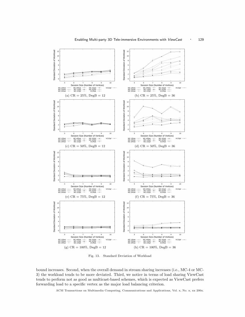
4.1.4 Workload
We measure the standard deviation of workload among vertices to investigate how evenly theforwarding load is divided. The workload is defined as the number of out-bound streams served
3 There is no need to plot the results of streams per view for MC-n as the number will be fixed by the constantof n.
ACM Transactions on Multimedia Computing, Communications and Applications, Vol. x, No. x, xx 200x.
128 · Z. Yang et al.
0
0.5
1
1.5
2
2.5
3
3.5
4
5 6 7 8 9 10
Ave
rage
Str
eam
s P
er V
iew
Session Size (Number of Vertices)
VC/RwkVC/Zipf 0
0.5
1
1.5
2
2.5
3
3.5
4
5 6 7 8 9 10
Ave
rage
Str
eam
s P
er V
iew
Session Size (Number of Vertices)
VC/RwkVC/Zipf
(a) CR = 25%, DegB = 12 (b) CR = 25%, DegB = 36
0
0.5
1
1.5
2
2.5
3
3.5
4
5 6 7 8 9 10
Ave
rage
Str
eam
s P
er V
iew
Session Size (Number of Vertices)
VC/RwkVC/Zipf 0
0.5
1
1.5
2
2.5
3
3.5
4
5 6 7 8 9 10
Ave
rage
Str
eam
s P
er V
iew
Session Size (Number of Vertices)
VC/RwkVC/Zipf
(c) CR = 50%, DegB = 12 (d) CR = 50%, DegB = 36
0
0.5
1
1.5
2
2.5
3
3.5
4
5 6 7 8 9 10
Ave
rage
Str
eam
s P
er V
iew
Session Size (Number of Vertices)
VC/RwkVC/Zipf 0
0.5
1
1.5
2
2.5
3
3.5
4
5 6 7 8 9 10
Ave
rage
Str
eam
s P
er V
iew
Session Size (Number of Vertices)
VC/RwkVC/Zipf
(e) CR = 75%, DegB = 12 (f) CR = 75%, DegB = 36
0
0.5
1
1.5
2
2.5
3
3.5
4
5 6 7 8 9 10
Ave
rage
Str
eam
s P
er V
iew
Session Size (Number of Vertices)
VC/RwkVC/Zipf 0
0.5
1
1.5
2
2.5
3
3.5
4
5 6 7 8 9 10
Ave
rage
Str
eam
s P
er V
iew
Session Size (Number of Vertices)
VC/RwkVC/Zipf
(g) CR = 100%, DegB = 12 (h) CR = 100%, DegB = 36
Fig. 12. Average Number of Streams Per View
by a vertex. The results of the workload standard deviation are plotted in Figure 13.Those figures indicate several trends. First, the standard deviation grows bigger as the degree
ACM Transactions on Multimedia Computing, Communications and Applications, Vol. x, No. x, xx 200x.
Enabling Multi-party 3D Tele-immersive Environments with ViewCast · 129
0
2
4
6
8
10
12
5 6 7 8 9 10
Sta
ndar
d D
evia
tion
of W
orkl
oad
Session Size (Number of Vertices)MC-1/RwkMC-2/RwkMC-3/Rwk
MC-4/RwkMC-1/ZipfMC-2/Zipf
MC-3/ZipfMC-4/Zipf
VC/Rwk
VC/Zipf
0
2
4
6
8
10
12
5 6 7 8 9 10
Sta
ndar
d D
evia
tion
of W
orkl
oad
Session Size (Number of Vertices)MC-1/RwkMC-2/RwkMC-3/Rwk
MC-4/RwkMC-1/ZipfMC-2/Zipf
MC-3/ZipfMC-4/Zipf
VC/Rwk
VC/Zipf
(a) CR = 25%, DegB = 12 (b) CR = 25%, DegB = 36
0
2
4
6
8
10
12
5 6 7 8 9 10
Sta
ndar
d D
evia
tion
of W
orkl
oad
Session Size (Number of Vertices)MC-1/RwkMC-2/RwkMC-3/Rwk
MC-4/RwkMC-1/ZipfMC-2/Zipf
MC-3/ZipfMC-4/Zipf
VC/Rwk
VC/Zipf
0
2
4
6
8
10
12
5 6 7 8 9 10
Sta
ndar
d D
evia
tion
of W
orkl
oad
Session Size (Number of Vertices)MC-1/RwkMC-2/RwkMC-3/Rwk
MC-4/RwkMC-1/ZipfMC-2/Zipf
MC-3/ZipfMC-4/Zipf
VC/Rwk
VC/Zipf
(c) CR = 50%, DegB = 12 (d) CR = 50%, DegB = 36
0
2
4
6
8
10
12
5 6 7 8 9 10
Sta
ndar
d D
evia
tion
of W
orkl
oad
Session Size (Number of Vertices)MC-1/RwkMC-2/RwkMC-3/Rwk
MC-4/RwkMC-1/ZipfMC-2/Zipf
MC-3/ZipfMC-4/Zipf
VC/Rwk
VC/Zipf
0
2
4
6
8
10
12
5 6 7 8 9 10
Sta
ndar
d D
evia
tion
of W
orkl
oad
Session Size (Number of Vertices)MC-1/RwkMC-2/RwkMC-3/Rwk
MC-4/RwkMC-1/ZipfMC-2/Zipf
MC-3/ZipfMC-4/Zipf
VC/Rwk
VC/Zipf
(e) CR = 75%, DegB = 12 (f) CR = 75%, DegB = 36
0
2
4
6
8
10
12
5 6 7 8 9 10
Sta
ndar
d D
evia
tion
of W
orkl
oad
Session Size (Number of Vertices)MC-1/RwkMC-2/RwkMC-3/Rwk
MC-4/RwkMC-1/ZipfMC-2/Zipf
MC-3/ZipfMC-4/Zipf
VC/Rwk
VC/Zipf
0
2
4
6
8
10
12
5 6 7 8 9 10
Sta
ndar
d D
evia
tion
of W
orkl
oad
Session Size (Number of Vertices)MC-1/RwkMC-2/RwkMC-3/Rwk
MC-4/RwkMC-1/ZipfMC-2/Zipf
MC-3/ZipfMC-4/Zipf
VC/Rwk
VC/Zipf
(g) CR = 100%, DegB = 12 (h) CR = 100%, DegB = 36
Fig. 13. Standard Deviation of Workload
bound increases. Second, when the overall demand in stream sharing increases (i.e., MC-4 or MC-3) the workload tends to be more deviated. Third, we notice in terms of load sharing ViewCasttends to perform not as good as multicast-based schemes, which is expected as ViewCast prefersforwarding load to a specific vertex as the major load balancing criterion.
ACM Transactions on Multimedia Computing, Communications and Applications, Vol. x, No. x, xx 200x.
130 · Z. Yang et al.
Table III. Bandwidth MeasurementUCB UIUC NCSA UCF
UCB → 41.8 Mbps 41.6 Mbps 39.3 Mbps
UIUC → 33.2 Mbps 538.7 Mbps 36.8 Mbps
NCSA → 33.4 Mbps 162.1 Mbps 38.1 Mbps
UCF → 36.4 Mbps 49.9 Mbps 38.9 Mbps
Table IV. End-to-End Application Delay MeasurementUCB ↔ UIUC 32 ms UIUC ↔ NCSA 0.41 ms
UCB ↔ NCSA 32 ms UIUC ↔ UCF 25 ms
UCB ↔ UCF 53 ms NCSA ↔ UCF 26 ms
4.1.5 Collateral Cost of ViewCast
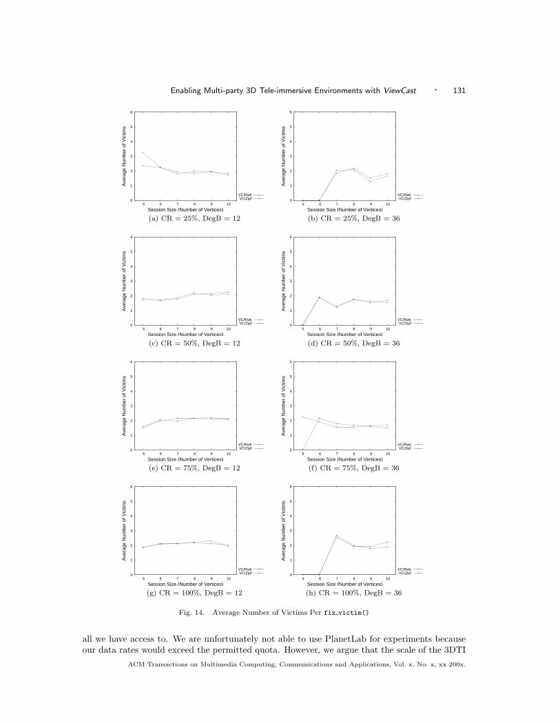
In ViewCast, due to the preemption of the network resource and the view change some verticesmay have their streams involuntarily discontinued. We call those broken links the victims. Moreprecisely, a victim is defined as a pair of (v, s) where v ∈ V and s ∈ S. After each view requestis served, the routine of fix victim() is called to fix any possible victims (refer to Table I). Inthe simulation, we measure the average number of victims. Inside fix victim(), if the numberof victims is greater than zero then we include it in the computation of the average number ofvictims. In other words, there are times the number of victims is 0 (in Internet evaluation, wefind this to be the majority which is about 88%). The size of the victim set indicates the scopeof affected vertex/stream pairs and the expected cost of fixing them. The results are plottedin Figure 14.4
The results indicate that in most cases the number of victims is small (around 2 ∼ 3). Notethat these broken links will be fixed by using a new parent vertex to supply the lost stream(Section 3.3). In the Internet experiments, we will show that the overall quality is resilient to aview change and stays stable over the time. Recall that because we don’t apply preemption inMC-n schemes, the number of victims will always be zero.
4.2 Internet Evaluation
We have integrated a prototype of the ViewCast model in our TEEVE testbed. Our goal is toobserve the implementation feasibility of ViewCast, the performance of response time, and theimpact of view change and network dynamics under the scale of Internet.
4.2.1 Network Characteristics
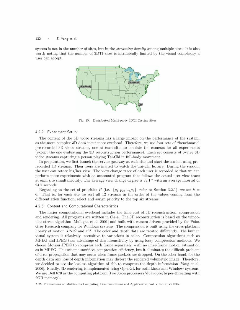
We currently have performed experiment using four 3DTI testing sites (Figure 15) includ-ing University of California at Berkeley (UCB), University of Illinois at Urbana-Champaign(UIUC), University of Central Florida (UCF), and National Center for Supercomputing Ap-plications (NCSA). We construct 3DTI environments in UCB, UIUC and NCSA while includingUCF only for testing purposes. We use 3D video streams recorded from remote Tai-Chi lecturesand deploy them in those testing sites.
We set up one service gateway at each location. The session controller is located at the site ofUIUC5. The connections among UCB, UCF, and UIUC run across the Internet2, while UIUC andNCSA are connected by the campus network. The network parameters are profiled and presentedin Table III and Table IV.
We cannot extend the experiment to a larger scale because so far the four testing sites are
4 As MC-n does not perform any preemption, there will be no victims of view change.5 The placement of the session controller has an impact on the system, for example, the response time of viewrequests. To ease the administration, we choose to place the session controller at UIUC.
ACM Transactions on Multimedia Computing, Communications and Applications, Vol. x, No. x, xx 200x.
Enabling Multi-party 3D Tele-immersive Environments with ViewCast · 131
0
1
2
3
4
5
6
5 6 7 8 9 10
Ave
rage
Num
ber
of V
ictim
s
Session Size (Number of Vertices)
VC/RwkVC/Zipf 0
1
2
3
4
5
6
5 6 7 8 9 10
Ave
rage
Num
ber
of V
ictim
s
Session Size (Number of Vertices)
VC/RwkVC/Zipf
(a) CR = 25%, DegB = 12 (b) CR = 25%, DegB = 36
0
1
2
3
4
5
6
5 6 7 8 9 10
Ave
rage
Num
ber
of V
ictim
s
Session Size (Number of Vertices)
VC/RwkVC/Zipf 0
1
2
3
4
5
6
5 6 7 8 9 10
Ave
rage
Num
ber
of V
ictim
s
Session Size (Number of Vertices)
VC/RwkVC/Zipf
(c) CR = 50%, DegB = 12 (d) CR = 50%, DegB = 36
0
1
2
3
4
5
6
5 6 7 8 9 10
Ave
rage
Num
ber
of V
ictim
s
Session Size (Number of Vertices)
VC/RwkVC/Zipf 0
1
2
3
4
5
6
5 6 7 8 9 10
Ave
rage
Num
ber
of V
ictim
s
Session Size (Number of Vertices)
VC/RwkVC/Zipf
(e) CR = 75%, DegB = 12 (f) CR = 75%, DegB = 36
0
1
2
3
4
5
6
5 6 7 8 9 10
Ave
rage
Num
ber
of V
ictim
s
Session Size (Number of Vertices)
VC/RwkVC/Zipf 0
1
2
3
4
5
6
5 6 7 8 9 10
Ave
rage
Num
ber
of V
ictim
s
Session Size (Number of Vertices)
VC/RwkVC/Zipf
(g) CR = 100%, DegB = 12 (h) CR = 100%, DegB = 36
Fig. 14. Average Number of Victims Per fix victim()
all we have access to. We are unfortunately not able to use PlanetLab for experiments becauseour data rates would exceed the permitted quota. However, we argue that the scale of the 3DTI
ACM Transactions on Multimedia Computing, Communications and Applications, Vol. x, No. x, xx 200x.
132 · Z. Yang et al.
system is not in the number of sites, but in the streaming density among multiple sites. It is alsoworth noting that the number of 3DTI sites is intrinsically limited by the visual complexity auser can accept.
UC Berkeley
UIUC/NCSA
UCF
Fig. 15. Distributed Multi-party 3DTI Testing Sites
4.2.2 Experiment Setup
The content of the 3D video streams has a large impact on the performance of the system,as the more complex 3D data incur more overhead. Therefore, we use four sets of “benchmark”pre-recorded 3D video streams, one at each site, to emulate the cameras for all experiments(except the one evaluating the 3D reconstruction performance). Each set consists of twelve 3Dvideo streams capturing a person playing Tai-Chi in full-body movement.
In preparation, we first launch the service gateway at each site and start the session using pre-recorded 3D streams. Then users are invited to watch the Tai-Chi lecture. During the session,the user can rotate his/her view. The view change trace of each user is recorded so that we canperform more experiments with an automated program that follows the actual user view traceat each site simultaneously. The average view change degree is 33.1 ◦ with an average interval of24.7 seconds.
Regarding to the set of priorities P (i.e. {p1, p2, ..., pk}, refer to Section 3.2.1), we set k =6. That is, for each site we sort all 12 streams in the order of the values coming from thedifferentiation function, select and assign priority to the top six streams.
4.2.3 Content and Computational Characteristics
The major computational overhead includes the time cost of 3D reconstruction, compressionand rendering. All programs are written in C++. The 3D reconstruction is based on the trinoc-ular stereo algorithm [Mulligan et al. 2001] and built with camera drivers provided by the PointGrey Research company for Windows systems. The compression is built using the cross-platformlibrary of motion JPEG and zlib. The color and depth data are treated differently. The humanvisual system is relatively insensitive to variations in color. Compression algorithms such asMPEG and JPEG take advantage of this insensitivity by using lossy compression methods. Wechoose Motion JPEG to compress each frame separately, with no inter-frame motion estimationas in MPEG. This scheme sacrifices compression efficiency, but it eliminates the difficult problemof error propagation that may occur when frame packets are dropped. On the other hand, for thedepth data any loss of depth information may distort the rendered volumetric image. Therefore,we decided to use the lossless algorithm of zlib to compress the depth information [Yang et al.2006]. Finally, 3D rendering is implemented using OpenGL for both Linux and Windows systems.We use Dell 670 as the computing platform (two Xeon processors/dual-core/hyper-threading with2GB memory).ACM Transactions on Multimedia Computing, Communications and Applications, Vol. x, No. x, xx 200x.
Enabling Multi-party 3D Tele-immersive Environments with ViewCast · 133
Table V. Overall Data Rates of 3D StreamsSite Rate
UCB 74.5 Mbps
UIUC 48.9 Mbps
NCSA 74.6 Mbps
UCF 60.9 Mbps
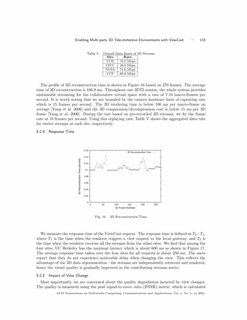
The profile of 3D reconstruction time is shown in Figure 16 based on 270 frames. The averagetime of 3D reconstruction is 106.9 ms. Throughout one 3DTI session, the whole system providessustainable streaming for the collaborative virtual space with a rate of 7-10 macro-frames persecond. It is worth noting that we are bounded by the camera hardware limit of capturing ratewhich is 15 frames per second. The 3D rendering time is below 100 ms per macro-frame onaverage [Yang et al. 2006] and the 3D compression/decompression cost is below 15 ms per 3Dframe [Yang et al. 2006]. During the test based on pre-recorded 3D streams, we fix the framerate at 10 frames per second. Using this replaying rate, Table V shows the aggregated data ratefor twelve streams at each site, respectively.
4.2.4 Response Time
0
0.02
0.04
0.06
0.08
0.1
0.12
0.14
0.16
0 50 100 150 200 250
3D R
econ
stru
ctio
n T
ime
(sec
ond)
3D Frame Number
3D Reconstruction Time
Fig. 16. 3D Reconstruction Time
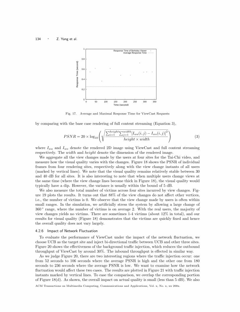
We measure the response time of the ViewCast request. The response time is defined as T2−T1,where T1 is the time when the renderer triggers a view request to the local gateway, and T2 isthe time when the renderer receives all the streams from the other sites. We find that among thefour sites, UC Berkeley has the maximal latency which is about 600 ms as shown in Figure 17.The average response time taken over the four sites for all requests is about 250 ms. The usersreport that they do not experience noticeable delay when changing the view. This reflects theadvantage of the 3D data representation - the streams are independently retrieved and rendered,hence the visual quality is gradually improved as the contributing streams arrive.
4.2.5 Impact of View Change
Most importantly, we are concerned about the quality degradation incurred by view changes.The quality is measured using the peak signal-to-noise ratio (PSNR) metric, which is calculated
ACM Transactions on Multimedia Computing, Communications and Applications, Vol. x, No. x, xx 200x.
134 · Z. Yang et al.
0
0.2
0.4
0.6
0.8
1
0 50 100 150 200 250 300 350
Res
pons
e T
ime
(sec
ond)
Time (second)
Response Time of Berkeley ViewerAverage Response Time
Fig. 17. Average and Maximal Response Time for ViewCast Requests
by comparing with the base case rendering of full content streaming (Equation 3),
PSNR = 20× log10
(√∑heighti=1
∑widthj=1 [Iwa(i, j)− Iwo(i, j)]
2
height× width
)(3)
where Iwa and Iwo denote the rendered 2D image using ViewCast and full content streamingrespectively. The width and height denote the dimension of the rendered image.
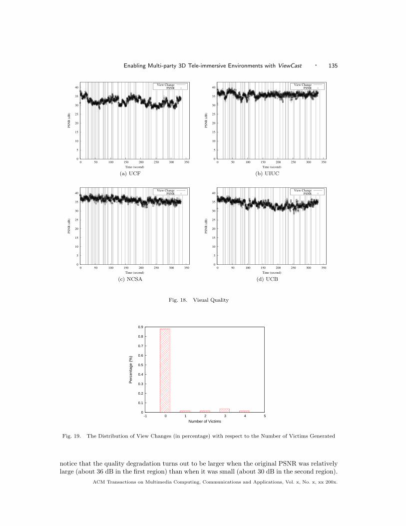
We aggregate all the view changes made by the users at four sites for the Tai-Chi video, andmeasure how the visual quality varies with the changes. Figure 18 shows the PSNR of individualframes from four rendering sites, respectively along with the view change instants of all users(marked by vertical lines). We note that the visual quality remains relatively stable between 30and 40 dB for all sites. It is also interesting to note that when multiple users change views atthe same time (where the view change lines become thick in Figure 18), the visual quality wouldtypically have a dip. However, the variance is usually within the bound of 5 dB.
We also measure the total number of victims across four sites incurred by view changes. Fig-ure 19 plots the results. It turns out that 88% of the view changes do not affect other vertices,i.e., the number of victims is 0. We observe that the view change made by users is often withinsmall ranges. In the simulation, we artificially stress the system by allowing a large change of360 ◦ range, where the number of victims is on average 2. With the real users, the majority ofview changes yields no victims. There are sometimes 1-4 victims (about 12% in total), and ourresults for visual quality (Figure 18) demonstrates that the victims are quickly fixed and hencethe overall quality does not vary largely.
4.2.6 Impact of Network Fluctuation
To evaluate the performance of ViewCast under the impact of the network fluctuation, wechoose UCB as the target site and inject bi-directional traffic between UCB and other three sites.Figure 20 shows the effectiveness of the background traffic injection, which reduces the outboundthroughput of ViewCast by around 30%. The inbound throughput is effected in similar way.
As we judge Figure 20, there are two interesting regions where the traffic injection occur: onefrom 52 seconds to 106 seconds where the average PSNR is high and the other one from 180seconds to 236 seconds where the average PSNR is low. We want to examine how the networkfluctuation would affect these two cases. The results are plotted in Figure 21 with traffic injectioninstants marked by vertical lines. To ease the comparison, we overlap the corresponding portionof Figure 18(d). As shown, the overall impact on actual quality is small (less than 5 dB). We alsoACM Transactions on Multimedia Computing, Communications and Applications, Vol. x, No. x, xx 200x.
Enabling Multi-party 3D Tele-immersive Environments with ViewCast · 135
0
5
10
15
20
25
30
35
40
0 50 100 150 200 250 300 350
PS
NR
(dB
)
Time (second)
View ChangePSNR
0
5
10
15
20
25
30
35
40
0 50 100 150 200 250 300 350
PS
NR
(dB
)
Time (second)
View ChangePSNR
(a) UCF (b) UIUC
0
5
10
15
20
25
30
35
40
0 50 100 150 200 250 300 350
PS
NR
(d
B)
Time (second)
View ChangePSNR
0
5
10
15
20
25
30
35
40
0 50 100 150 200 250 300 350
PS
NR
(d
B)
Time (second)
View ChangePSNR
(c) NCSA (d) UCB
Fig. 18. Visual Quality
0
0.1
0.2
0.3
0.4
0.5
0.6
0.7
0.8
0.9
-1 0 1 2 3 4 5
Per
cent
age
(%)
Number of Victims
Fig. 19. The Distribution of View Changes (in percentage) with respect to the Number of Victims Generated
notice that the quality degradation turns out to be larger when the original PSNR was relativelylarge (about 36 dB in the first region) than when it was small (about 30 dB in the second region).
ACM Transactions on Multimedia Computing, Communications and Applications, Vol. x, No. x, xx 200x.
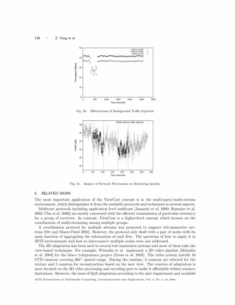
136 · Z. Yang et al.
0
10
20
30
40
50
0 500 1000 1500 2000 2500 3000
Thr
ough
put (
Mbp
s)
Time (second)
UCB to UIUCUCB to NCSA
UCB to UCF
Fig. 20. Effectiveness of Background Traffic Injection
28
30
32
34
36
38
0 50 100 150 200 250 300 350
PS
NR
(dB
)
Time (second)
PSNR without Traffic Injection
Fig. 21. Impact of Network Fluctuation on Rendering Quality
5. RELATED WORK
The most important application of the ViewCast concept is in the multi-party/multi-streamenvironment, which distinguishes it from the available protocols and techniques in several aspects.
Multicast protocols including application level multicast [Jannotti et al. 2000; Banerjee et al.2002; Chu et al. 2000] are mostly concerned with the efficient transmission of particular stream(s)for a group of receivers. In contrast, ViewCast is a higher-level concept which focuses on thecoordination of multi-streaming among multiple groups.
A coordination protocol for multiple streams was proposed to support tele-immersive sys-tems [Ott and Mayer-Patel 2004]. However, the protocol only dealt with a pair of nodes with itsmain function of aggregating the information of each flow. The questions of how to apply it in3DTI environments and how to interconnect multiple nodes were not addressed.
The 3D adaptation has been used in several tele-immersion systems and most of them take theview-based techniques. For example, Wurmlin et al. implement a 3D video pipeline [Murmlinet al. 2003] for the blue-c telepresence project [Gross et al. 2003]. The video system installs 16CCD cameras covering 360 ◦ spatial range. During the runtime, 3 cameras are selected for thetexture and 5 cameras for reconstruction based on the user view. The concern of adaptation ismore focused on the 3D video processing and encoding part to make it affordable within resourcelimitations. However, the issue of QoS adaptation according to the user requirement and availableACM Transactions on Multimedia Computing, Communications and Applications, Vol. x, No. x, xx 200x.
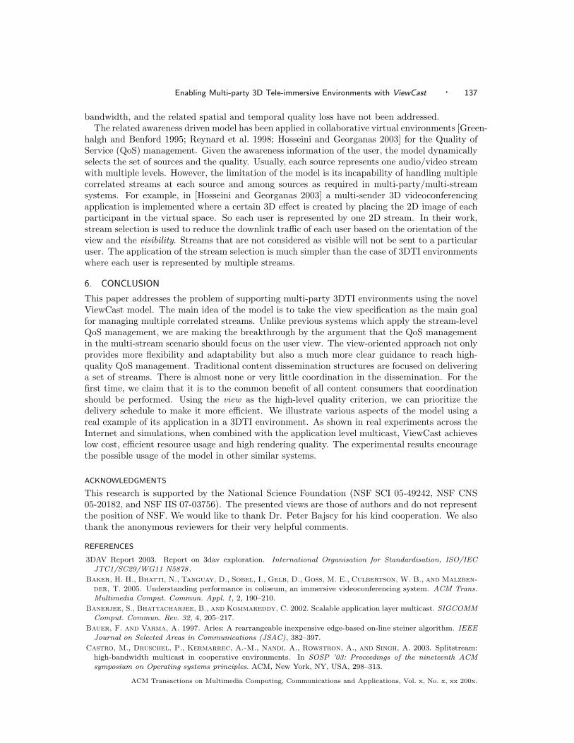
Enabling Multi-party 3D Tele-immersive Environments with ViewCast · 137
bandwidth, and the related spatial and temporal quality loss have not been addressed.The related awareness driven model has been applied in collaborative virtual environments [Green-
halgh and Benford 1995; Reynard et al. 1998; Hosseini and Georganas 2003] for the Quality ofService (QoS) management. Given the awareness information of the user, the model dynamicallyselects the set of sources and the quality. Usually, each source represents one audio/video streamwith multiple levels. However, the limitation of the model is its incapability of handling multiplecorrelated streams at each source and among sources as required in multi-party/multi-streamsystems. For example, in [Hosseini and Georganas 2003] a multi-sender 3D videoconferencingapplication is implemented where a certain 3D effect is created by placing the 2D image of eachparticipant in the virtual space. So each user is represented by one 2D stream. In their work,stream selection is used to reduce the downlink traffic of each user based on the orientation of theview and the visibility. Streams that are not considered as visible will not be sent to a particularuser. The application of the stream selection is much simpler than the case of 3DTI environmentswhere each user is represented by multiple streams.
6. CONCLUSION
This paper addresses the problem of supporting multi-party 3DTI environments using the novelViewCast model. The main idea of the model is to take the view specification as the main goalfor managing multiple correlated streams. Unlike previous systems which apply the stream-levelQoS management, we are making the breakthrough by the argument that the QoS managementin the multi-stream scenario should focus on the user view. The view-oriented approach not onlyprovides more flexibility and adaptability but also a much more clear guidance to reach high-quality QoS management. Traditional content dissemination structures are focused on deliveringa set of streams. There is almost none or very little coordination in the dissemination. For thefirst time, we claim that it is to the common benefit of all content consumers that coordinationshould be performed. Using the view as the high-level quality criterion, we can prioritize thedelivery schedule to make it more efficient. We illustrate various aspects of the model using areal example of its application in a 3DTI environment. As shown in real experiments across theInternet and simulations, when combined with the application level multicast, ViewCast achieveslow cost, efficient resource usage and high rendering quality. The experimental results encouragethe possible usage of the model in other similar systems.
ACKNOWLEDGMENTS
This research is supported by the National Science Foundation (NSF SCI 05-49242, NSF CNS05-20182, and NSF IIS 07-03756). The presented views are those of authors and do not representthe position of NSF. We would like to thank Dr. Peter Bajscy for his kind cooperation. We alsothank the anonymous reviewers for their very helpful comments.
REFERENCES
3DAV Report 2003. Report on 3dav exploration. International Organisation for Standardisation, ISO/IECJTC1/SC29/WG11 N5878 .
Baker, H. H., Bhatti, N., Tanguay, D., Sobel, I., Gelb, D., Goss, M. E., Culbertson, W. B., and Malzben-der, T. 2005. Understanding performance in coliseum, an immersive videoconferencing system. ACM Trans.Multimedia Comput. Commun. Appl. 1, 2, 190–210.
Banerjee, S., Bhattacharjee, B., and Kommareddy, C. 2002. Scalable application layer multicast. SIGCOMMComput. Commun. Rev. 32, 4, 205–217.
Bauer, F. and Varma, A. 1997. Aries: A rearrangeable inexpensive edge-based on-line steiner algorithm. IEEEJournal on Selected Areas in Communications (JSAC), 382–397.
Castro, M., Druschel, P., Kermarrec, A.-M., Nandi, A., Rowstron, A., and Singh, A. 2003. Splitstream:high-bandwidth multicast in cooperative environments. In SOSP ’03: Proceedings of the nineteenth ACMsymposium on Operating systems principles. ACM, New York, NY, USA, 298–313.
ACM Transactions on Multimedia Computing, Communications and Applications, Vol. x, No. x, xx 200x.
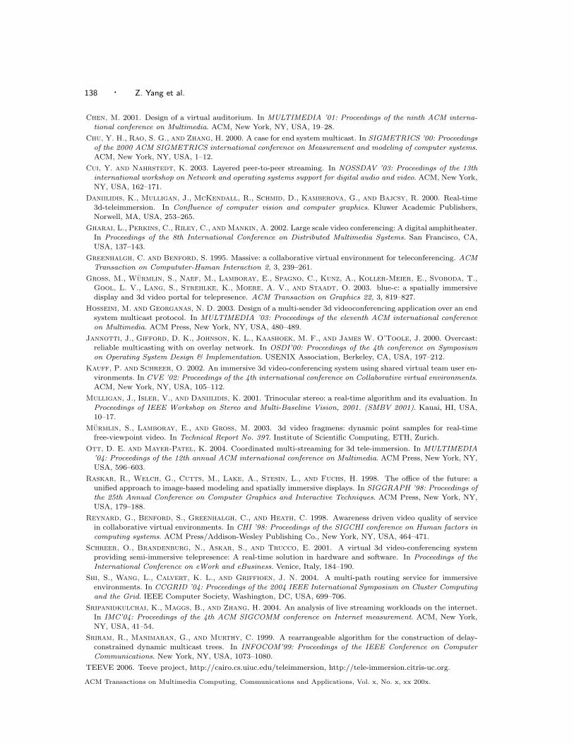
138 · Z. Yang et al.
Chen, M. 2001. Design of a virtual auditorium. In MULTIMEDIA ’01: Proceedings of the ninth ACM interna-tional conference on Multimedia. ACM, New York, NY, USA, 19–28.
Chu, Y. H., Rao, S. G., and Zhang, H. 2000. A case for end system multicast. In SIGMETRICS ’00: Proceedingsof the 2000 ACM SIGMETRICS international conference on Measurement and modeling of computer systems.ACM, New York, NY, USA, 1–12.
Cui, Y. and Nahrstedt, K. 2003. Layered peer-to-peer streaming. In NOSSDAV ’03: Proceedings of the 13thinternational workshop on Network and operating systems support for digital audio and video. ACM, New York,NY, USA, 162–171.
Daniilidis, K., Mulligan, J., McKendall, R., Schmid, D., Kamberova, G., and Bajcsy, R. 2000. Real-time3d-teleimmersion. In Confluence of computer vision and computer graphics. Kluwer Academic Publishers,Norwell, MA, USA, 253–265.
Gharai, L., Perkins, C., Riley, C., and Mankin, A. 2002. Large scale video conferencing: A digital amphitheater.In Proceedings of the 8th International Conference on Distributed Multimedia Systems. San Francisco, CA,USA, 137–143.
Greenhalgh, C. and Benford, S. 1995. Massive: a collaborative virtual environment for teleconferencing. ACMTransaction on Compututer-Human Interaction 2, 3, 239–261.
Gross, M., Wurmlin, S., Naef, M., Lamboray, E., Spagno, C., Kunz, A., Koller-Meier, E., Svoboda, T.,Gool, L. V., Lang, S., Strehlke, K., Moere, A. V., and Staadt, O. 2003. blue-c: a spatially immersivedisplay and 3d video portal for telepresence. ACM Transaction on Graphics 22, 3, 819–827.
Hosseini, M. and Georganas, N. D. 2003. Design of a multi-sender 3d videoconferencing application over an endsystem multicast protocol. In MULTIMEDIA ’03: Proceedings of the eleventh ACM international conferenceon Multimedia. ACM Press, New York, NY, USA, 480–489.
Jannotti, J., Gifford, D. K., Johnson, K. L., Kaashoek, M. F., and James W. O’Toole, J. 2000. Overcast:reliable multicasting with on overlay network. In OSDI’00: Proceedings of the 4th conference on Symposiumon Operating System Design & Implementation. USENIX Association, Berkeley, CA, USA, 197–212.
Kauff, P. and Schreer, O. 2002. An immersive 3d video-conferencing system using shared virtual team user en-vironments. In CVE ’02: Proceedings of the 4th international conference on Collaborative virtual environments.ACM, New York, NY, USA, 105–112.
Mulligan, J., Isler, V., and Daniilidis, K. 2001. Trinocular stereo: a real-time algorithm and its evaluation. InProceedings of IEEE Workshop on Stereo and Multi-Baseline Vision, 2001. (SMBV 2001). Kauai, HI, USA,10–17.
Murmlin, S., Lamboray, E., and Gross, M. 2003. 3d video fragmens: dynamic point samples for real-timefree-viewpoint video. In Technical Report No. 397. Institute of Scientific Computing, ETH, Zurich.
Ott, D. E. and Mayer-Patel, K. 2004. Coordinated multi-streaming for 3d tele-immersion. In MULTIMEDIA’04: Proceedings of the 12th annual ACM international conference on Multimedia. ACM Press, New York, NY,USA, 596–603.
Raskar, R., Welch, G., Cutts, M., Lake, A., Stesin, L., and Fuchs, H. 1998. The office of the future: aunified approach to image-based modeling and spatially immersive displays. In SIGGRAPH ’98: Proceedings ofthe 25th Annual Conference on Computer Graphics and Interactive Techniques. ACM Press, New York, NY,USA, 179–188.
Reynard, G., Benford, S., Greenhalgh, C., and Heath, C. 1998. Awareness driven video quality of servicein collaborative virtual environments. In CHI ’98: Proceedings of the SIGCHI conference on Human factors incomputing systems. ACM Press/Addison-Wesley Publishing Co., New York, NY, USA, 464–471.
Schreer, O., Brandenburg, N., Askar, S., and Trucco, E. 2001. A virtual 3d video-conferencing systemproviding semi-immersive telepresence: A real-time solution in hardware and software. In Proceedings of theInternational Conference on eWork and eBusiness. Venice, Italy, 184–190.
Shi, S., Wang, L., Calvert, K. L., and Griffioen, J. N. 2004. A multi-path routing service for immersiveenvironments. In CCGRID ’04: Proceedings of the 2004 IEEE International Symposium on Cluster Computingand the Grid. IEEE Computer Society, Washington, DC, USA, 699–706.
Sripanidkulchai, K., Maggs, B., and Zhang, H. 2004. An analysis of live streaming workloads on the internet.In IMC’04: Proceedings of the 4th ACM SIGCOMM conference on Internet measurement. ACM, New York,NY, USA, 41–54.
Sriram, R., Manimaran, G., and Murthy, C. 1999. A rearrangeable algorithm for the construction of delay-constrained dynamic multicast trees. In INFOCOM’99: Proceedings of the IEEE Conference on ComputerCommunications. New York, NY, USA, 1073–1080.
TEEVE 2006. Teeve project, http://cairo.cs.uiuc.edu/teleimmersion, http://tele-immersion.citris-uc.org.
ACM Transactions on Multimedia Computing, Communications and Applications, Vol. x, No. x, xx 200x.
Enabling Multi-party 3D Tele-immersive Environments with ViewCast · 139
Yang, Z., Cui, Y., Anwar, Z., Bocchino, R., Kiyanclar, N., Nahrstedt, K., Campbell, R. H., and Yurcik,W. 2006. Real-time 3d video compression for tele-immersive environments. In MMCN ’06: SPIE MultimediaComputing and Networking. San Jose, CA, USA, 12–23.
Yang, Z., Nahrstedt, K., Cui, Y., Yu, B., Liang, J., hack Jung, S., and Bajscy, R. 2005. Teeve: the nextgeneration architecture for tele-immersive environments. In ISM ’05: Proceedings of the 7th IEEE InternationalSymposium on Multimedia. Irvine, CA, USA, 112–119.
Yang, Z., Wu, W., Nahrstedt, K., Kurillo, G., and Bajcsy, R. 2007. Viewcast: view dissemination andmanagement for multi-party 3d tele-immersive environments. In MULTIMEDIA ’07: Proceedings of the 15thinternational conference on Multimedia. ACM, New York, NY, USA, 882–891.
Yang, Z., Yu, B., Nahrstedt, K., and Bajscy, R. 2006. A multi-stream adaptation framework for bandwidthmanagement in 3d tele-immersion. In NOSSDAV ’06: Proceedings of the 2006 international workshop onNetwork and operating systems support for digital audio and video. ACM, New York, NY, USA, 1–6.
Received xxx 20xx; xxx 20xx; accepted xxx 20xx
ACM Transactions on Multimedia Computing, Communications and Applications, Vol. x, No. x, xx 200x.