Embed Size (px)
Citation preview

1
Enabling Cross-Technology Communication from LoRa toZigBee via Payload Encoding in Sub-1 GHz Bands
JUNYANG SHI, DI MU, and MO SHA∗, State University of New York at Binghamton, USA
Low-power wireless mesh networks (LPWMNs) have been widely used in wireless monitoring and controlapplications. Although LPWMNs work satisfactorily most of the time thanks to decades of research, theyare often complex, inelastic to change, and difficult to manage once the networks are deployed. Moreover,the deliveries of control commands, especially those carrying urgent information such as emergency alarms,suffer long delay, since the messages must go through the hop-by-hop transport. Recent studies show thatadding low-power wide-area network (LPWAN) radios such as LoRa onto the LPWMN devices (e.g., ZigBee)effectively overcomes the limitation. However, users have shown a marked reluctance to embrace the newheterogeneous communication approach because of the cost of hardware modification. In this paper, weintroduce LoRaBee, a novel LoRa to ZigBee cross-technology communication (CTC) approach, which leveragesthe energy emission in the Sub-1 GHz bands as the carrier to deliver information. Although LoRa and ZigBeeadopt distinct modulation techniques, LoRaBee sends information from LoRa to ZigBee by putting specificbytes in the payload of legitimate LoRa packets. The bytes are selected such that the corresponding LoRa chirpscan be recognized by the ZigBee devices through sampling the received signal strength (RSS). Experimentalresults show that our LoRaBee provides reliable CTC communication from LoRa to ZigBee with the throughputof up to 281.61bps in the Sub-1 GHz bands.
CCS Concepts: • Networks → Network protocol design; Sensor networks; Network management.
Additional Key Words and Phrases: Cross-technology Communication, LoRa, ZigBee, Low-power wirelessmesh network
ACM Reference Format:Junyang Shi, Di Mu, and Mo Sha. 2021. Enabling Cross-Technology Communication from LoRa to ZigBeevia Payload Encoding in Sub-1 GHz Bands. ACM Trans. Sensor Netw. 1, 1, Article 1 (January 2021), 27 pages.https://doi.org/10.1145/3470452
1 INTRODUCTIONThe Internet of Things (IoT) refers to a broad vision whereby things such as everyday objects, places,and environments are connected to each other via the Internet [27]. Manywireless technologies (e.g.,ZigBee [45], WiFi [35], and Bluetooth [2]) are readily available to form the networks which connectthose things for various IoT applications. Many of those networks follow the low-power wirelessmesh network (LPWMN) paradigm and have been widely deployed for monitoring and controlapplications. For instance, sensors and actuators equipped with ZigBee radios have been used for adecade in industrial facilities, such as steel mills, oil refineries, and chemical plants, to monitor and∗Corresponding author
Part of this article was published in Proceedings of the ICNP [29].Authors’ address: Junyang Shi; Di Mu; Mo Sha, State University of New York at Binghamton, 4400 Vestal Parkway East,Binghamton, NY, 13902, USA, {jshi28,dmu1,msha}@binghamton.edu.
Permission to make digital or hard copies of all or part of this work for personal or classroom use is granted without feeprovided that copies are not made or distributed for profit or commercial advantage and that copies bear this notice andthe full citation on the first page. Copyrights for components of this work owned by others than ACM must be honored.Abstracting with credit is permitted. To copy otherwise, or republish, to post on servers or to redistribute to lists, requiresprior specific permission and/or a fee. Request permissions from [email protected].© 2021 Association for Computing Machinery.1550-4859/2021/1-ART1 $15.00https://doi.org/10.1145/3470452
ACM Trans. Sensor Netw., Vol. 1, No. 1, Article 1. Publication date: January 2021.
1:2 J. Shi et al.
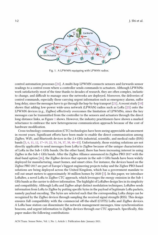
Fig. 1. A LPWMN equipping with LPWAN radios.
control automation processes [24]. A multi-hop LPWMN connects sensors and forwards sensorreadings to a control room where a controller sends commands to actuators. Although LPWMNswork satisfactorily most of the time thanks to decades of research, they are often complex, inelasticto change, and difficult to manage once the networks are deployed. Moreover, the deliveries ofcontrol commands, especially those carrying urgent information such as emergency alarms, sufferlong delay, since the messages have to go through the hop-by-hop transport [21]. A recent study [10]shows that adding low-power wide-area network (LPWAN) radios such as LoRa [23] onto theLPWMN devices (e.g., ZigBee) effectively overcomes the limitation of LPWMNs, since the keymessages can be transmitted from the controller to the sensors and actuators through the directlong-distance links, as Figure 1 shows. However, the industry practitioners have shown a markedreluctance to embrace the new heterogeneous communication approach because of the cost ofhardware modification.
Cross-technology communication (CTC) technologies have been seeing appreciable advancementin recent years. Significant efforts have been made to enable the direct communication amongZigBee, WiFi, and Bluetooth devices in the 2.4 GHz industrial, scientific, and medical radio (ISM)bands [5, 6, 11, 12, 17–19, 22, 33, 34, 37, 38, 40–43]. Unfortunately, those existing solutions are notdirectly applicable to send messages from LoRa to ZigBee because of the unique characteristicsof LoRa in the Sub-1 GHz bands. On the other hand, there has been increasing interest in usingZigBee in the Sub-1 GHz bands. After the ZigBee Alliance announced its ZigBee PRO 2017 with thedual-band option [46], the ZigBee devices that operate in the sub-1 GHz bands have been widelydeployed for manufacturing, smart homes, and smart cities. For instance, the devices based on theZigbee PRO 2017 are part of Europe’s biggest engineering projects today and the Zigbee PRO-basedsolutions are being deployed across the United Kingdom, which has a government mandate toroll out smart meters to approximately 30 million homes by 2020 [3]. In this paper, we introduceLoRaBee, a novel LoRa to ZigBee CTC approach, which leverages the energy emission in the Sub-1GHz bands as the carrier to deliver information. The highlight of LoRaBee design lies in its simplicityand compatibility. Although LoRa and ZigBee adopt distinct modulation techniques, LoRaBee sendsinformation from LoRa to ZigBee by putting specific bytes in the payload of legitimate LoRa packets,namely payload encoding. The bytes are selected such that the corresponding LoRa chirps can berecognized by the ZigBee devices through sampling the received signal strength (RSS). This designensures full compatibility with the commercial off-the-shelf (COTS) LoRa and ZigBee devices.A LoRa base station can disseminate the network management messages, time synchronizationbeacons, and urgent information to ZigBee devices through our CTC approach. Specifically, thispaper makes the following contributions:
ACM Trans. Sensor Netw., Vol. 1, No. 1, Article 1. Publication date: January 2021.
Enabling CTC from LoRa to ZigBee in Sub-1 GHz Bands 1:3
• To our knowledge, this is the first paper to investigate CTC from LoRa to ZigBee in the Sub-1GHz bands, distinguished with previous work pertaining to CTC among WiFi, ZigBee, andBluetooth devices in the 2.4 GHz band.
• This paper performs an empirical study that investigates the characteristics of LoRa from aCTC’s point of view and provides a set of new observations.
• This paper introduces LoRaBee, a novel LoRa to ZigBee CTC approach. By elaboratelytuning the LoRa’s central carrier frequency and packet payload, a ZigBee device is capable ofdecoding the information carried by the LoRa chirps by purely sampling the RSS. LoRaBeedoes not require any hardware modification.
• This paper presents a new Time Division Multiple Access (TDMA) based MAC protocol,which allows a LoRa device to time synchronize and deliver information to a network ofZigBee devices through LoRaBee.
• LoRaBee has been implemented and tested on real hardware. Experimental results show thatLoRaBee provides reliable CTC communication from LoRa to ZigBee with the throughput ofup to 281.61bps1 in Sub-1 GHz bands.
The remainder of the paper is organized as follows. Section 2 reviews the related work andSection 3 discusses the background of LoRa and ZigBee. Section 4 introduces our empirical study.Sections 5 and 6 present the design of our LoRaBee and MAC protocol. Section 7 evaluates LoRaBeeand Section 8 concludes the paper.
2 RELATEDWORKSThere has been increasing interest in developing CTC technologies in recent years. Significantefforts have been made to enable the direct communication among ZigBee, WiFi, and Bluetoothdevices in the 2.4 GHz ISM bands [5, 6, 11, 12, 16–18, 22, 33, 34, 37–43]. The key idea of packetlevel CTC is that heterogeneous wireless devices operating in the shared spectrum need to sensethe presence of signal via channel energy detection, such as received signal strength (RSS) andchannel state information (CSI). Most of the CTC technologies leverage the energy intensity, gapbetween energy appearance, and duration of radio energy to modulate data. For instance, Chebroluet al. proposed to enable the communication from WiFi to ZigBee devices based on sensing andinterpreting energy profiles and convey information by modulating the WiFi energy duration toconstruct an alphabet set [5]. Zhang et al. developed GapSense which leverages the sequences ofenergy bursts to modulate symbol [41]. Kim et al. proposed FreeBee which adjusts the appearance ofWiFi beacons in the time dimension to transmit modulated data [18, 19]. Yin et al. designed C-Morsewhich controls the presence of data traffic to deliver information [38]. Guo et al. designed a CTCtechnique that employs modulation techniques in both the amplitude and temporal dimensions tooptimize the throughput over a noisy channel [12]. Li et al. developed WEBee which uses WiFipackets to directly emulate the ZigBee signals in the physical-layer [22]. Yin et al. proposed touse the presence and absence of energy profiles to convey information among heterogeneouswireless devices [37]. More recently, Zheng et al. developed StripComm which is an interference-aware CTC modulation and demodulation scheme [43]. Gawłowicz et al. designed LtFi that allowsdirect communication between LTE-U (LTE in Unlicensed) and WiFi devices, which can enablecollaboration between co-located LTE-U and WiFi networks to mitigate interference [9, 47]. Zhenget al. designed a transparent cross-technology opportunistic forwarding method to mitigate Cross-Technology Interference (CTI) [44]. Guo et al. developed ZigFi that uses channel state informationto convey data from ZigBee to WiFi [11]. Yu et al. [39] and Hao et al. [16] proposed to use CTC for
1As a comparison for the throughput value, a LoRa device pair provides a throughput of up to 11kbps under the samesettings.
ACM Trans. Sensor Netw., Vol. 1, No. 1, Article 1. Publication date: January 2021.

1:4 J. Shi et al.
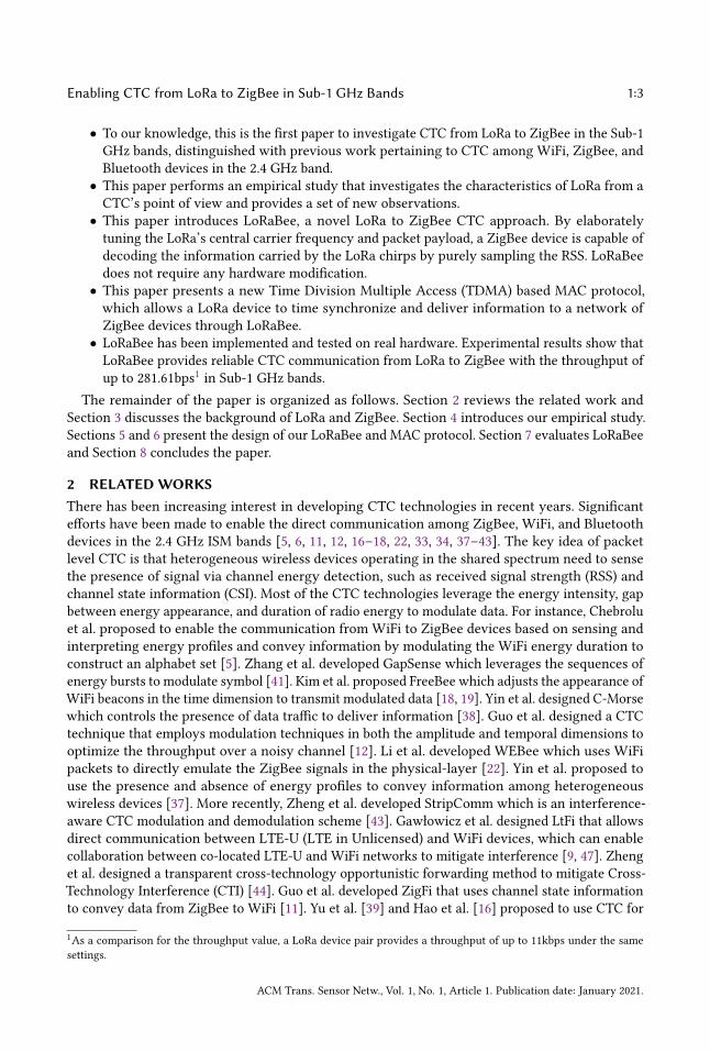
(a) A LoRa transmission with upchirps, downchirps and datachirps.
(b) A single LoRa data chirp.
Fig. 2. LoRa modulation.
clock synchronization. Jiang et al. developed SymBee that achieves symbol-level CTC from ZigBeeto WiFi [33]. Jiang et al. [17] and Chi et al. [6] enabled the CTC between ZigBee and Bluetoothdevices. Wang et al. [32] leveraged the CTC technology to turn the pervasively-deployed WiFiaccess point into a multi-user transmitter, which transmits different packets to multiple ZigBeedevices in parallel. Xia et al. [36] extended the communication range from ZigBee to WiFi andestablished symmetric CTC over asymmetric channels. In contrast to previous studies on CTCamong ZigBee, WiFi, and Bluetooth devices in the 2.4 GHz ISM bands, this paper investigates thecharacteristics of LoRa in the Sub-1 GHz bands; to our knowledge, it represents the first systematicstudy on CTC from LoRa to ZigBee. Our work is therefore orthogonal and complementary.LoRaBee enables the CTC from LoRa to ZigBee in the Sub-1 GHz bands by encoding the LoRa
packet payload with specific bytes, whose corresponding LoRa chirps can be detected by the ZigBeedevice through sampling the RSS. Specifically, the ZigBee device detects the sudden RSS valuedrop caused by each LoRa chirp and uses the time intervals of all RSS value drops to decodeinformation. Unfortunately, LoRaBee is not applicable in the 2.4 GHz band because the LoRa devicetransmits much faster and the ZigBee device is not capable of sampling RSS frequent enough todetect individual LoRa chirps. To enable the CTC from LoRa to ZigBee in the 2.4 GHz, we havedeveloped another approach, which encodes information using the sizes of the LoRa payloads [28].The ZigBee device uses the number of the consecutive RSS values higher than a threshold to decodeinformation. Such an approach [28] encodes less information in each time unit, which results inlower throughput if applied in the Sub-1 GHz bands compared to LoRaBee. Therefore, our twoCTC approaches reported in this paper and [28] are complementary with each other.
3 BACKGROUND3.1 LoRa OverviewLPWANs are emerging as a new paradigm in the field of IoT connectivity [31]. LoRa is an industryLPWAN technology which has been initiated by Semtech [7] to build scalable IoT networks. LoRaprovides a radio modulation scheme, which leverages chirp spread spectrum (CSS) modulation todeliver data. LoRa utilizes the unlicensed ISM bands and incorporates a variation of CSS techniqueto encode information.Modulation technique: LoRa employs the CSS modulation to modulate signals. It uses frequencychirps with a constantly increasing (upchirp) or decreasing (downchirp) frequency which sweeps
ACM Trans. Sensor Netw., Vol. 1, No. 1, Article 1. Publication date: January 2021.
Enabling CTC from LoRa to ZigBee in Sub-1 GHz Bands 1:5
Table 1. Key LoRa physical-layer parameters.
Parameter Options𝑓𝑐 between 902 MHz to 928 Mhz𝑆𝐹 7, 8, 9, 10, 11, 12
𝐵𝑊 (KHz) 125, 250, 500𝐶𝑅 4/5, 4/6, 4/7, 4/8𝐶𝑅𝐶 on or off
through a predefined bandwidth. Figure 2(a) plots an example LoRa transmission with multiplechirps in the frequency variation over time. The first 10 upchirps are preamble whose frequencystarts from the minimum frequency (𝑓𝑚𝑖𝑛) to the maximum frequency (𝑓𝑚𝑎𝑥 ). They are followedby 2.25 downchirps annotated as Start Frame Delimiter (SFD) that goes from 𝑓𝑚𝑎𝑥 to 𝑓𝑚𝑖𝑛 . Therest chirps carry data. The modulated data chirps start at different frequency positions representdifferent encoded bits. When each data chirp reaches 𝑓𝑚𝑎𝑥 , it wraps around and starts from 𝑓𝑚𝑖𝑛 ,as Figure 2(a) shows. In other words, LoRa uses different starting frequency of the chirp signal toencode different information. As Figure 2(b) shows, the value in the y-axis represents the encodedbits. More LoRa chirps are concatenated to represent more data bits.Key physical-layer parameters: LoRa allows users to change the central carrier frequency (𝑓𝑐 ),frequency bandwidth (𝐵𝑊 ), spreading factor (𝑆𝐹 ), coding rate (𝐶𝑅), and cyclic redundancy check(𝐶𝑅𝐶). Table 1 lists the possible values for each parameter in the United States. 𝑓𝑐 determinesthe central carrier frequency for data transmission2. 𝐵𝑊 determines the magnitude of frequencyvariation (𝑓𝑚𝑎𝑥 − 𝑓𝑚𝑖𝑛), representing the channel width. Each chirp consists of 2𝑆𝐹 chips which cancarry 𝑆𝐹 bits of data. The time duration of one LoRa chirp is:
𝑇𝑐ℎ𝑖𝑟𝑝 =2𝑆𝐹
𝐵𝑊(1)
𝐶𝑅 uses the Hamming code [15] to provide redundancy and correct error bits. This number refersto the proportion of the transmitted bits that actually carry information. LoRa allows users toenable the CRC check.Input: The LoRa transceivers provided by Semtech only accept hexadecimal strings as input. Theupper layer protocols must translate their data into the hexadecimal format. For instance, “0x6A”may be input into the LoRa transceiver to carry 106.
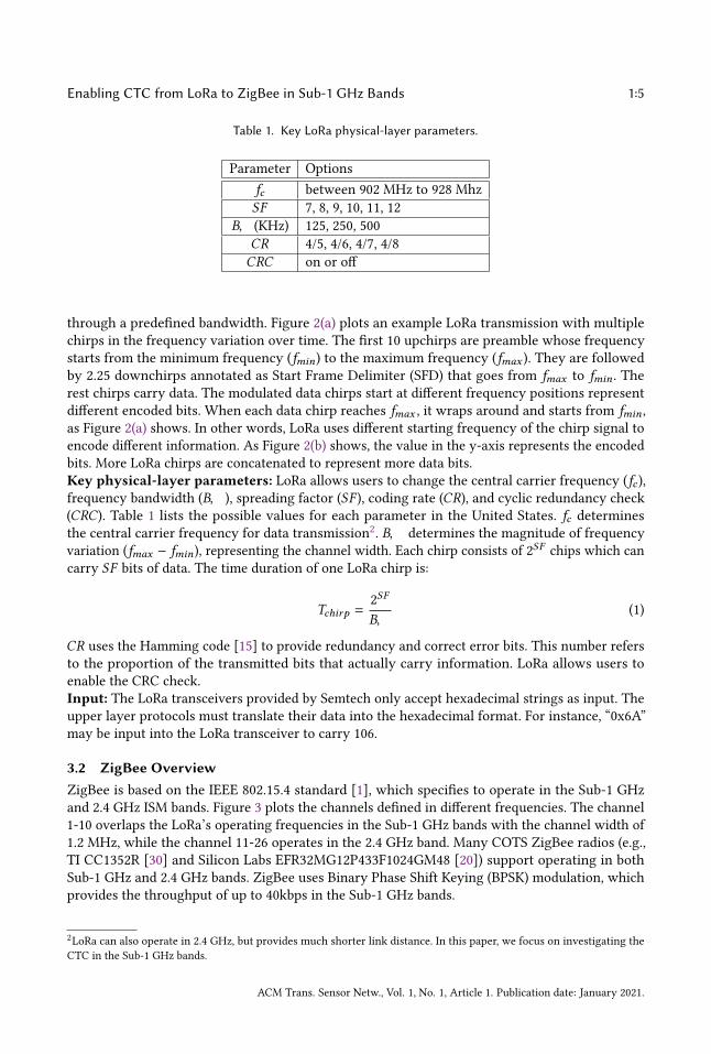
3.2 ZigBee OverviewZigBee is based on the IEEE 802.15.4 standard [1], which specifies to operate in the Sub-1 GHzand 2.4 GHz ISM bands. Figure 3 plots the channels defined in different frequencies. The channel1-10 overlaps the LoRa’s operating frequencies in the Sub-1 GHz bands with the channel width of1.2 MHz, while the channel 11-26 operates in the 2.4 GHz band. Many COTS ZigBee radios (e.g.,TI CC1352R [30] and Silicon Labs EFR32MG12P433F1024GM48 [20]) support operating in bothSub-1 GHz and 2.4 GHz bands. ZigBee uses Binary Phase Shift Keying (BPSK) modulation, whichprovides the throughput of up to 40kbps in the Sub-1 GHz bands.
2LoRa can also operate in 2.4 GHz, but provides much shorter link distance. In this paper, we focus on investigating theCTC in the Sub-1 GHz bands.
ACM Trans. Sensor Netw., Vol. 1, No. 1, Article 1. Publication date: January 2021.
1:6 J. Shi et al.
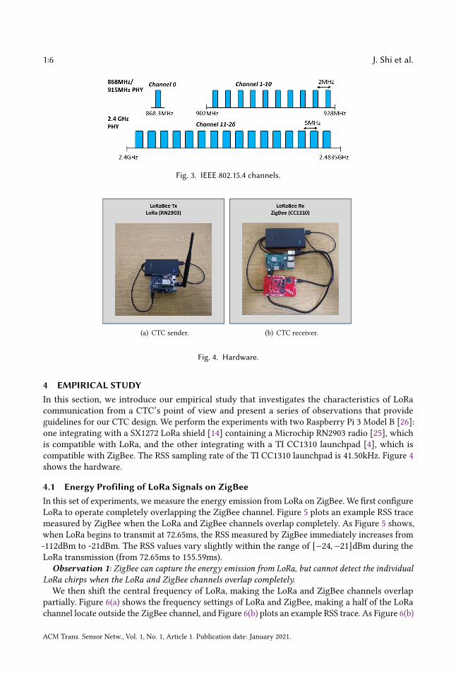
Fig. 3. IEEE 802.15.4 channels.
(a) CTC sender. (b) CTC receiver.
Fig. 4. Hardware.
4 EMPIRICAL STUDYIn this section, we introduce our empirical study that investigates the characteristics of LoRacommunication from a CTC’s point of view and present a series of observations that provideguidelines for our CTC design. We perform the experiments with two Raspberry Pi 3 Model B [26]:one integrating with a SX1272 LoRa shield [14] containing a Microchip RN2903 radio [25], whichis compatible with LoRa, and the other integrating with a TI CC1310 launchpad [4], which iscompatible with ZigBee. The RSS sampling rate of the TI CC1310 launchpad is 41.50kHz. Figure 4shows the hardware.
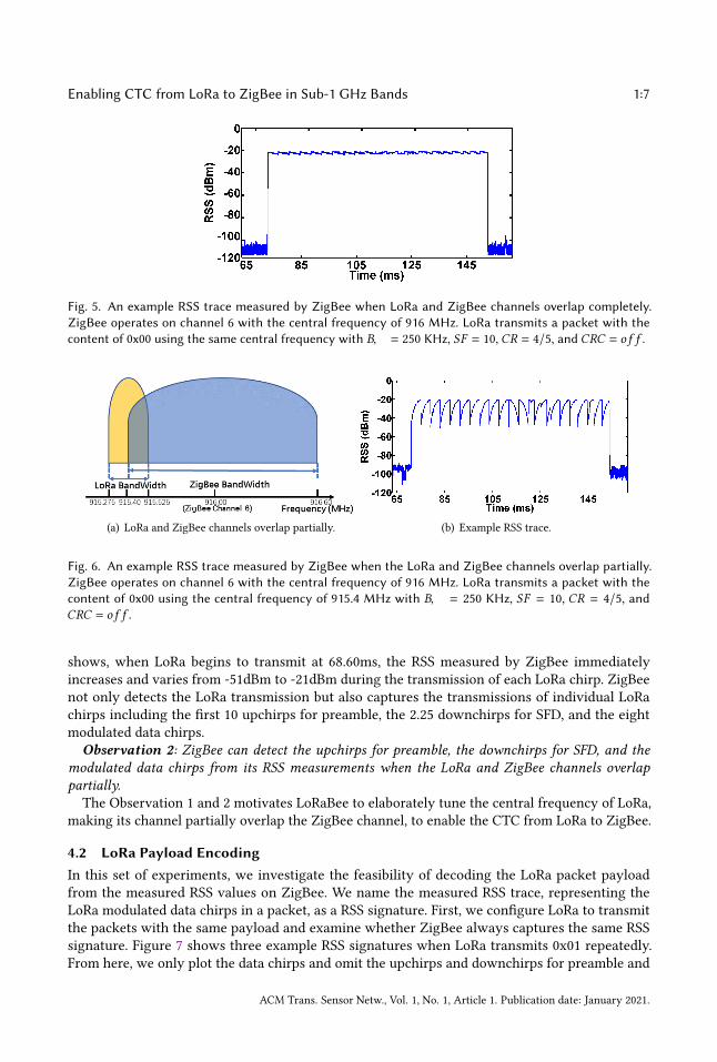
4.1 Energy Profiling of LoRa Signals on ZigBeeIn this set of experiments, we measure the energy emission from LoRa on ZigBee. We first configureLoRa to operate completely overlapping the ZigBee channel. Figure 5 plots an example RSS tracemeasured by ZigBee when the LoRa and ZigBee channels overlap completely. As Figure 5 shows,when LoRa begins to transmit at 72.65ms, the RSS measured by ZigBee immediately increases from-112dBm to -21dBm. The RSS values vary slightly within the range of [−24,−21]dBm during theLoRa transmission (from 72.65ms to 155.59ms).
Observation 1: ZigBee can capture the energy emission from LoRa, but cannot detect the individualLoRa chirps when the LoRa and ZigBee channels overlap completely.We then shift the central frequency of LoRa, making the LoRa and ZigBee channels overlap
partially. Figure 6(a) shows the frequency settings of LoRa and ZigBee, making a half of the LoRachannel locate outside the ZigBee channel, and Figure 6(b) plots an example RSS trace. As Figure 6(b)
ACM Trans. Sensor Netw., Vol. 1, No. 1, Article 1. Publication date: January 2021.
Enabling CTC from LoRa to ZigBee in Sub-1 GHz Bands 1:7
Fig. 5. An example RSS trace measured by ZigBee when LoRa and ZigBee channels overlap completely.ZigBee operates on channel 6 with the central frequency of 916 MHz. LoRa transmits a packet with thecontent of 0x00 using the same central frequency with 𝐵𝑊 = 250 KHz, 𝑆𝐹 = 10, 𝐶𝑅 = 4/5, and 𝐶𝑅𝐶 = 𝑜 𝑓 𝑓 .
(a) LoRa and ZigBee channels overlap partially. (b) Example RSS trace.
Fig. 6. An example RSS trace measured by ZigBee when the LoRa and ZigBee channels overlap partially.ZigBee operates on channel 6 with the central frequency of 916 MHz. LoRa transmits a packet with thecontent of 0x00 using the central frequency of 915.4 MHz with 𝐵𝑊 = 250 KHz, 𝑆𝐹 = 10, 𝐶𝑅 = 4/5, and𝐶𝑅𝐶 = 𝑜 𝑓 𝑓 .
shows, when LoRa begins to transmit at 68.60ms, the RSS measured by ZigBee immediatelyincreases and varies from -51dBm to -21dBm during the transmission of each LoRa chirp. ZigBeenot only detects the LoRa transmission but also captures the transmissions of individual LoRachirps including the first 10 upchirps for preamble, the 2.25 downchirps for SFD, and the eightmodulated data chirps.
Observation 2: ZigBee can detect the upchirps for preamble, the downchirps for SFD, and themodulated data chirps from its RSS measurements when the LoRa and ZigBee channels overlappartially.The Observation 1 and 2 motivates LoRaBee to elaborately tune the central frequency of LoRa,
making its channel partially overlap the ZigBee channel, to enable the CTC from LoRa to ZigBee.
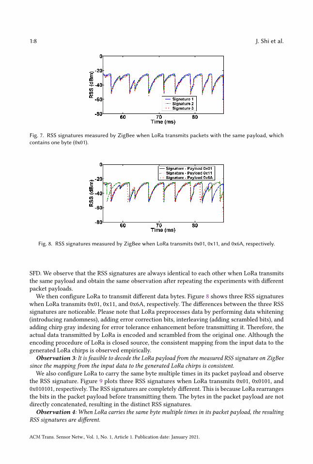
4.2 LoRa Payload EncodingIn this set of experiments, we investigate the feasibility of decoding the LoRa packet payloadfrom the measured RSS values on ZigBee. We name the measured RSS trace, representing theLoRa modulated data chirps in a packet, as a RSS signature. First, we configure LoRa to transmitthe packets with the same payload and examine whether ZigBee always captures the same RSSsignature. Figure 7 shows three example RSS signatures when LoRa transmits 0x01 repeatedly.From here, we only plot the data chirps and omit the upchirps and downchirps for preamble and
ACM Trans. Sensor Netw., Vol. 1, No. 1, Article 1. Publication date: January 2021.
1:8 J. Shi et al.
Fig. 7. RSS signatures measured by ZigBee when LoRa transmits packets with the same payload, whichcontains one byte (0x01).
Fig. 8. RSS signatures measured by ZigBee when LoRa transmits 0x01, 0x11, and 0x6A, respectively.
SFD. We observe that the RSS signatures are always identical to each other when LoRa transmitsthe same payload and obtain the same observation after repeating the experiments with differentpacket payloads.We then configure LoRa to transmit different data bytes. Figure 8 shows three RSS signatures
when LoRa transmits 0x01, 0x11, and 0x6A, respectively. The differences between the three RSSsignatures are noticeable. Please note that LoRa preprocesses data by performing data whitening(introducing randomness), adding error correction bits, interleaving (adding scrambled bits), andadding chirp gray indexing for error tolerance enhancement before transmitting it. Therefore, theactual data transmitted by LoRa is encoded and scrambled from the original one. Although theencoding procedure of LoRa is closed source, the consistent mapping from the input data to thegenerated LoRa chirps is observed empirically.
Observation 3: It is feasible to decode the LoRa payload from the measured RSS signature on ZigBeesince the mapping from the input data to the generated LoRa chirps is consistent.
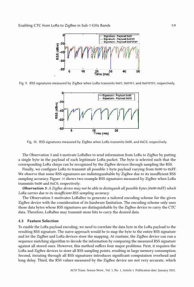
We also configure LoRa to carry the same byte multiple times in its packet payload and observethe RSS signature. Figure 9 plots three RSS signatures when LoRa transmits 0x01, 0x0101, and0x010101, respectively. The RSS signatures are completely different. This is because LoRa rearrangesthe bits in the packet payload before transmitting them. The bytes in the packet payload are notdirectly concatenated, resulting in the distinct RSS signatures.
Observation 4: When LoRa carries the same byte multiple times in its packet payload, the resultingRSS signatures are different.
ACM Trans. Sensor Netw., Vol. 1, No. 1, Article 1. Publication date: January 2021.
Enabling CTC from LoRa to ZigBee in Sub-1 GHz Bands 1:9
,
Fig. 9. RSS signatures measured by ZigBee when LoRa transmits 0x01, 0x0101, and 0x010101, respectively.
Fig. 10. RSS signatures measured by ZigBee when LoRa transmits 0x00, and 0xC0, respectively.
The Observation 3 and 4 motivate LoRaBee to send information from LoRa to ZigBee by puttinga single byte in the payload of each legitimate LoRa packet. The byte is selected such that thecorresponding LoRa chirps can be recognized by the ZigBee devices through sampling the RSS.Finally, we configure LoRa to transmit all possible 1-byte payload varying from 0x00 to 0xFF.
We observe that some RSS signatures are indistinguishable by ZigBee due to its insufficient RSSsampling accuracy. Figure 10 shows two example RSS signatures measured by ZigBee when LoRatransmits 0x00 and 0xC0, respectively.
Observation 5: A ZigBee device may not be able to distinguish all possible bytes (0x00-0xFF) whichLoRa carries due to its insufficient RSS sampling accuracy.The Observation 5 motivates LoRaBee to generate a tailored encoding scheme for the given
ZigBee device with the consideration of its hardware limitation. The encoding scheme only usesthose data bytes whose RSS signatures are distinguishable by the ZigBee device to carry the CTCdata. Therefore, LoRaBee may transmit more bits to carry the desired data.
4.3 Feature SelectionTo enable the LoRa payload encoding, we need to correlate the data byte in the LoRa payload to theresulting RSS signature. The naive approach would be to map the byte to the entire RSS signatureand let the ZigBee and LoRa devices store the mapping. At runtime, the ZigBee device can run asequence matching algorithm to decode the information by comparing the measured RSS signatureagainst all stored ones. However, this method suffers four major problems. First, it requires theLoRa and ZigBee devices to store all RSS sampling points, resulting in large memory consumption.Second, iterating through all RSS signatures introduces significant computation overhead andlong delay. Third, the RSS values measured by the ZigBee device are not very accurate, which
ACM Trans. Sensor Netw., Vol. 1, No. 1, Article 1. Publication date: January 2021.

1:10 J. Shi et al.
Fig. 11. Example RSS signature captured when LoRa transmits 0x01 with eight LoRa chirps. The time durationbetween the start of LoRa data chirps and their corresponding RSS drop are marked.
may introduce some sequence matching errors. Fourth, the measured RSS values depend on thedistance between the LoRa and ZigBee devices. Thus, every ZigBee device must record the RSSsignatures and perform the calibration, which maps each LoRa payload value to its own measuredRSS signature, introducing significant overhead. The abovementioned problems motivate us toidentify a lightweight feature which can be easily extracted from the RSS signature and used reliablyto decode the LoRa packet payload. The selected feature must not depend on the distance betweenthe LoRa and ZigBee devices. Therefore, only one ZigBee device in the network performs thecalibration and then shares the mapping between LoRa payload values and RSS signatures to otherdevices.We observe that there always exists a sudden drop in the measured RSS values during the
transmission of each LoRa chirp. This is because the LoRa’s CSS modulation requires the radio togradually increase its operating frequency and wrap around to 𝑓𝑚𝑖𝑛 when it reaches 𝑓𝑚𝑎𝑥 . Whenthe LoRa and ZigBee channels overlap partially, the RSS measurement experiences a significantdecrease when LoRa begins to use the frequency located outside the ZigBee channel. Since LoRauses the different starting frequency of data chirp signal to encode different information, the timeof those sudden drops in the RSS measurements depends on the data in the LoRa packet payload.Figure 11 plots an example of RSS signature with the marked time duration between the starts ofdata chirps and their corresponding sudden RSS value decreases. Our ZigBee device generates 177RSS samples during the transmission of a LoRa chirp. We mark the number of RSS samples betweenthe start of each data chirp and the sudden RSS value drop 𝑁𝑖 (𝑖 ∈ [1, 8]) in Figure 11. It is importantto note that this feature neither relies on the absolute RSS values nor depends on the distancebetween the LoRa and ZigBee devices. Therefore, only one ZigBee device in the network performsthe calibration and then shares the mapping between LoRa payload values and RSS signatures toother devices. Table 2 lists some example 𝑁𝑖 records when LoRa transmits different bytes. The 10LoRa upchirps for preamble are used by ZigBee to synchronize its clock and identify the start ofeach LoRa data chirp. Please note that a low RSS sampling rate of RSS may decrease the number ofdistinguishable RSS signatures and the ZigBee device can detect all LoRa signatures when its RSSsampling rate is larger than the LoRa chip rate.
Observation 6: The eight3 numbers of RSS samples which capture the sudden RSS value drops canbe used as the feature to identify the RSS signature.
3LoRa may use more than eight data chirps to carry one byte in its packet payload. The number is decided by Eq.2 (seeSection 5.2).
ACM Trans. Sensor Netw., Vol. 1, No. 1, Article 1. Publication date: January 2021.
Enabling CTC from LoRa to ZigBee in Sub-1 GHz Bands 1:11
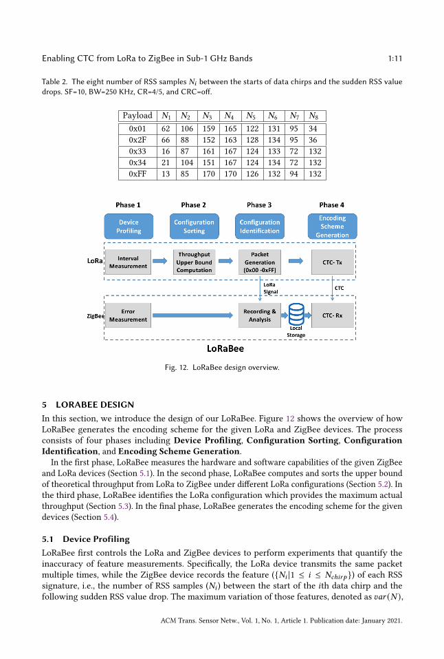
Table 2. The eight number of RSS samples 𝑁𝑖 between the starts of data chirps and the sudden RSS valuedrops. SF=10, BW=250 KHz, CR=4/5, and CRC=off.
Payload 𝑁1 𝑁2 𝑁3 𝑁4 𝑁5 𝑁6 𝑁7 𝑁8
0x01 62 106 159 165 122 131 95 340x2F 66 88 152 163 128 134 95 360x33 16 87 161 167 124 133 72 1320x34 21 104 151 167 124 134 72 1320xFF 13 85 170 170 126 132 94 132
Fig. 12. LoRaBee design overview.
5 LORABEE DESIGNIn this section, we introduce the design of our LoRaBee. Figure 12 shows the overview of howLoRaBee generates the encoding scheme for the given LoRa and ZigBee devices. The processconsists of four phases including Device Profiling, Configuration Sorting, ConfigurationIdentification, and Encoding Scheme Generation.
In the first phase, LoRaBee measures the hardware and software capabilities of the given ZigBeeand LoRa devices (Section 5.1). In the second phase, LoRaBee computes and sorts the upper boundof theoretical throughput from LoRa to ZigBee under different LoRa configurations (Section 5.2). Inthe third phase, LoRaBee identifies the LoRa configuration which provides the maximum actualthroughput (Section 5.3). In the final phase, LoRaBee generates the encoding scheme for the givendevices (Section 5.4).
5.1 Device ProfilingLoRaBee first controls the LoRa and ZigBee devices to perform experiments that quantify theinaccuracy of feature measurements. Specifically, the LoRa device transmits the same packetmultiple times, while the ZigBee device records the feature ({𝑁𝑖 |1 ≤ 𝑖 ≤ 𝑁𝑐ℎ𝑖𝑟𝑝 }) of each RSSsignature, i.e., the number of RSS samples (𝑁𝑖 ) between the start of the 𝑖th data chirp and thefollowing sudden RSS value drop. The maximum variation of those features, denoted as 𝑣𝑎𝑟 (𝑁 ),
ACM Trans. Sensor Netw., Vol. 1, No. 1, Article 1. Publication date: January 2021.
1:12 J. Shi et al.
(a) Impact of 𝑆𝐹 . (b) Impact of 𝐵𝑊 .
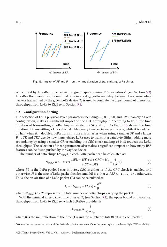
Fig. 13. Impact of 𝑆𝐹 and 𝐵𝑊 on the time duration of transmitting LoRa chirps.
is recorded by LoRaBee to serve as the guard space among RSS signatures4 (see Section 5.3).LoRaBee then measures the minimal time interval 𝑇𝑔 (software delay) between two consecutivepackets transmitted by the given LoRa device.𝑇𝑔 is used to compute the upper bound of theoreticalthroughput from LoRa to ZigBee in Section 5.2.
5.2 Configuration SortingThe selection of LoRa physical-layer parameters including 𝑆𝐹 , 𝐵𝑊 , 𝐶𝑅, and 𝐶𝑅𝐶 , namely a LoRaconfiguration, makes a significant impact on the CTC throughput. According to Eq. 1, the timeduration of transmitting a LoRa chirp is decided by 𝑆𝐹 and 𝐵𝑊 . As Figure 13 shows, the timeduration of transmitting a LoRa chirp doubles every time 𝑆𝐹 increases by one, while it is reducedby half when 𝐵𝑊 doubles. LoRa transmits the chirps faster when using a smaller 𝑆𝐹 and a larger𝐵𝑊 . 𝐶𝑅 and 𝐶𝑅𝐶 decide how many chirps LoRa uses to transmit a data byte. Either adding moreredundancy by using a smaller 𝐶𝑅 or enabling the 𝐶𝑅𝐶 check (adding 16 bits) reduces the LoRathroughput. The selection of those parameters also makes a significant impact on how many RSSfeatures can be distinguished by the ZigBee device.
The number of data chirps (𝑁𝑐ℎ𝑖𝑟𝑝 ) in each LoRa packet can be calculated as:
𝑁𝑐ℎ𝑖𝑟𝑝 = 8 +𝑚𝑎𝑥 (⌈8𝑃𝐿 − 4𝑆𝐹 + 8 +𝐶𝑅𝐶 + 𝐻
4(𝑆𝐹 − 𝐷𝐸) ⌉ ∗ 4𝐶𝑅
, 0) (2)
where 𝑃𝐿 is the LoRa payload size in bytes, 𝐶𝑅𝐶 is either 16 if the 𝐶𝑅𝐶 check is enabled or 0otherwise, 𝐻 is the size of LoRa packet header, and 𝐷𝐸 is either 2 if 𝑆𝐹 ∈ {11, 12} or 0 otherwise.Thus, the on-air time of a LoRa packet (𝑇𝑠 ) can be calculated as:
𝑇𝑠 = (𝑁𝑐ℎ𝑖𝑟𝑝 + 12.25) ∗ 2𝑆𝐹
𝐵𝑊(3)
where 𝑁𝑐ℎ𝑖𝑟𝑝 + 12.25 represents the total number of LoRa chirps carrying the packet.With the minimal inter-packet time interval 𝑇𝑔 (see Section 5.1), the upper bound of theoretical
throughput from LoRa to ZigBee, which LoRaBee provides, is:
𝐷𝑏𝑜𝑢𝑛𝑑 =8
𝑇𝑠 +𝑇𝑔(4)
where 8 is the multiplication of the time (1s) and the number of bits (8 bits) in each packet.
4We use the maximum variation of the LoRa chirp’s features 𝑣𝑎𝑟 (𝑁 ) as the guard space to achieve high CTC reliability.
ACM Trans. Sensor Netw., Vol. 1, No. 1, Article 1. Publication date: January 2021.
Enabling CTC from LoRa to ZigBee in Sub-1 GHz Bands 1:13
With Eq. 2, 3, and 4, LoRaBee can compute the upper bound of throughput 𝐷𝑏𝑜𝑢𝑛𝑑 , which itprovides under each LoRa configuration (6 ∗ 3 ∗ 4 ∗ 2 = 144 configurations in total). LoRaBeethen sorts all configurations based on their 𝐷𝑏𝑜𝑢𝑛𝑑 values in the descending order (denoted as{𝐷𝑏𝑜𝑢𝑛𝑑 [𝑖] |1 ≤ 𝑖 ≤ 144}).Please note that the 𝐷𝑏𝑜𝑢𝑛𝑑 values are calculated with the assumption that the ZigBee device
can distinguish all possible bytes (0x00-0xFF) from its measured RSS features. According to ourObservation 5 in Section 4, a ZigBee device may not be able to distinguish all of them due toits insufficient RSS sampling accuracy. Therefore, LoRaBee must compute the actual throughput𝐷𝑎𝑐𝑡𝑢𝑎𝑙 under different configurations and then identify the best one which provides the maximum𝐷𝑎𝑐𝑡𝑢𝑎𝑙 (see Section 5.3).
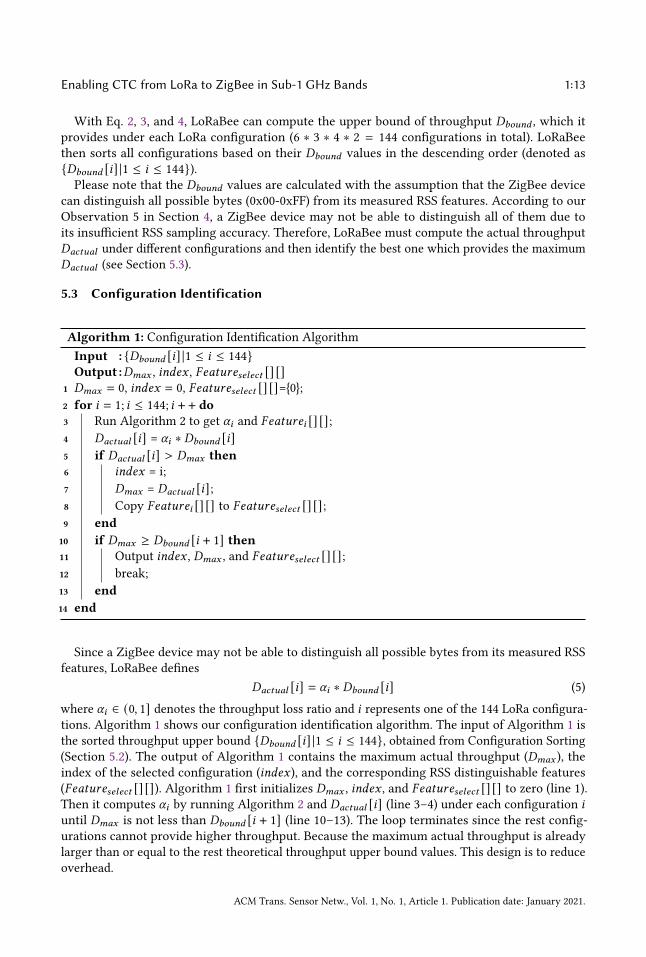
5.3 Configuration Identification
Algorithm 1: Configuration Identification AlgorithmInput : {𝐷𝑏𝑜𝑢𝑛𝑑 [𝑖] |1 ≤ 𝑖 ≤ 144}Output :𝐷𝑚𝑎𝑥 , 𝑖𝑛𝑑𝑒𝑥 , 𝐹𝑒𝑎𝑡𝑢𝑟𝑒𝑠𝑒𝑙𝑒𝑐𝑡 [] []
1 𝐷𝑚𝑎𝑥 = 0, 𝑖𝑛𝑑𝑒𝑥 = 0, 𝐹𝑒𝑎𝑡𝑢𝑟𝑒𝑠𝑒𝑙𝑒𝑐𝑡 [] []={0};2 for 𝑖 = 1; 𝑖 ≤ 144; 𝑖 + + do3 Run Algorithm 2 to get 𝛼𝑖 and 𝐹𝑒𝑎𝑡𝑢𝑟𝑒𝑖 [] [];4 𝐷𝑎𝑐𝑡𝑢𝑎𝑙 [𝑖] = 𝛼𝑖 ∗ 𝐷𝑏𝑜𝑢𝑛𝑑 [𝑖]5 if 𝐷𝑎𝑐𝑡𝑢𝑎𝑙 [𝑖] > 𝐷𝑚𝑎𝑥 then6 𝑖𝑛𝑑𝑒𝑥 = i;7 𝐷𝑚𝑎𝑥 = 𝐷𝑎𝑐𝑡𝑢𝑎𝑙 [𝑖];8 Copy 𝐹𝑒𝑎𝑡𝑢𝑟𝑒𝑖 [] [] to 𝐹𝑒𝑎𝑡𝑢𝑟𝑒𝑠𝑒𝑙𝑒𝑐𝑡 [] [];9 end
10 if 𝐷𝑚𝑎𝑥 ≥ 𝐷𝑏𝑜𝑢𝑛𝑑 [𝑖 + 1] then11 Output 𝑖𝑛𝑑𝑒𝑥 , 𝐷𝑚𝑎𝑥 , and 𝐹𝑒𝑎𝑡𝑢𝑟𝑒𝑠𝑒𝑙𝑒𝑐𝑡 [] [];12 break;13 end14 end
Since a ZigBee device may not be able to distinguish all possible bytes from its measured RSSfeatures, LoRaBee defines
𝐷𝑎𝑐𝑡𝑢𝑎𝑙 [𝑖] = 𝛼𝑖 ∗ 𝐷𝑏𝑜𝑢𝑛𝑑 [𝑖] (5)
where 𝛼𝑖 ∈ (0, 1] denotes the throughput loss ratio and 𝑖 represents one of the 144 LoRa configura-tions. Algorithm 1 shows our configuration identification algorithm. The input of Algorithm 1 isthe sorted throughput upper bound {𝐷𝑏𝑜𝑢𝑛𝑑 [𝑖] |1 ≤ 𝑖 ≤ 144}, obtained from Configuration Sorting(Section 5.2). The output of Algorithm 1 contains the maximum actual throughput (𝐷𝑚𝑎𝑥 ), theindex of the selected configuration (𝑖𝑛𝑑𝑒𝑥), and the corresponding RSS distinguishable features(𝐹𝑒𝑎𝑡𝑢𝑟𝑒𝑠𝑒𝑙𝑒𝑐𝑡 [] []). Algorithm 1 first initializes 𝐷𝑚𝑎𝑥 , 𝑖𝑛𝑑𝑒𝑥 , and 𝐹𝑒𝑎𝑡𝑢𝑟𝑒𝑠𝑒𝑙𝑒𝑐𝑡 [] [] to zero (line 1).Then it computes 𝛼𝑖 by running Algorithm 2 and 𝐷𝑎𝑐𝑡𝑢𝑎𝑙 [𝑖] (line 3–4) under each configuration 𝑖
until 𝐷𝑚𝑎𝑥 is not less than 𝐷𝑏𝑜𝑢𝑛𝑑 [𝑖 + 1] (line 10–13). The loop terminates since the rest config-urations cannot provide higher throughput. Because the maximum actual throughput is alreadylarger than or equal to the rest theoretical throughput upper bound values. This design is to reduceoverhead.
ACM Trans. Sensor Netw., Vol. 1, No. 1, Article 1. Publication date: January 2021.
1:14 J. Shi et al.
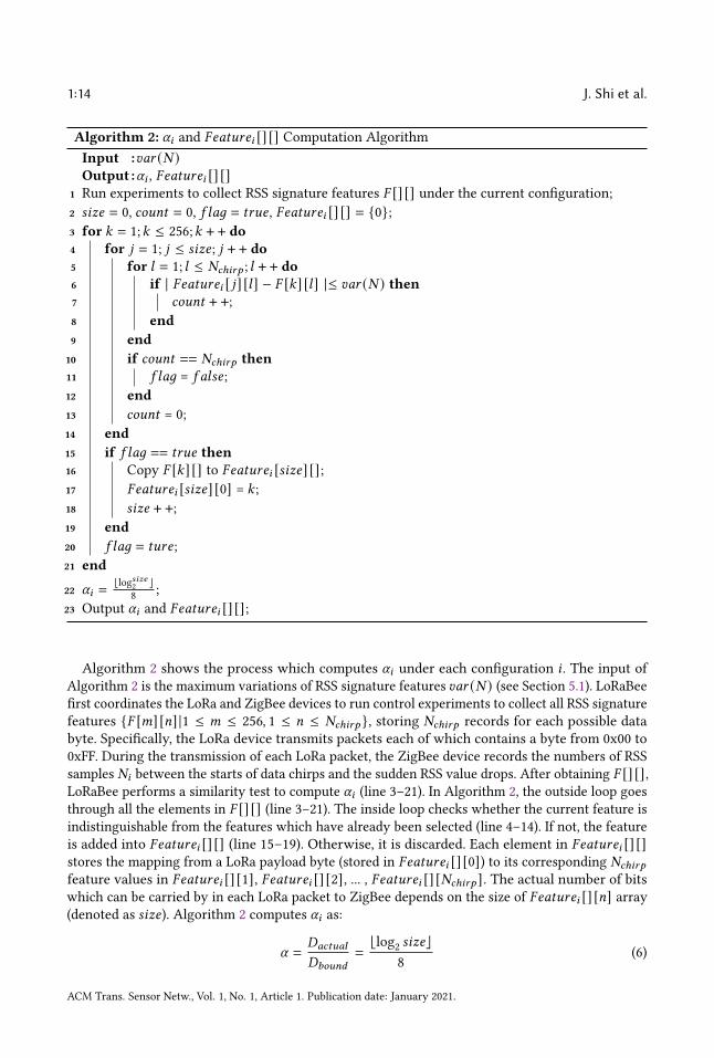
Algorithm 2: 𝛼𝑖 and 𝐹𝑒𝑎𝑡𝑢𝑟𝑒𝑖 [] [] Computation AlgorithmInput :𝑣𝑎𝑟 (𝑁 )Output :𝛼𝑖 , 𝐹𝑒𝑎𝑡𝑢𝑟𝑒𝑖 [] []
1 Run experiments to collect RSS signature features 𝐹 [] [] under the current configuration;2 𝑠𝑖𝑧𝑒 = 0, 𝑐𝑜𝑢𝑛𝑡 = 0, 𝑓 𝑙𝑎𝑔 = 𝑡𝑟𝑢𝑒 , 𝐹𝑒𝑎𝑡𝑢𝑟𝑒𝑖 [] [] = {0};3 for 𝑘 = 1;𝑘 ≤ 256;𝑘 + + do4 for 𝑗 = 1; 𝑗 ≤ 𝑠𝑖𝑧𝑒; 𝑗 + + do5 for 𝑙 = 1; 𝑙 ≤ 𝑁𝑐ℎ𝑖𝑟𝑝 ; 𝑙 + + do6 if | 𝐹𝑒𝑎𝑡𝑢𝑟𝑒𝑖 [ 𝑗] [𝑙] − 𝐹 [𝑘] [𝑙] |≤ 𝑣𝑎𝑟 (𝑁 ) then7 𝑐𝑜𝑢𝑛𝑡 + +;8 end9 end
10 if 𝑐𝑜𝑢𝑛𝑡 == 𝑁𝑐ℎ𝑖𝑟𝑝 then11 𝑓 𝑙𝑎𝑔 = 𝑓 𝑎𝑙𝑠𝑒;12 end13 𝑐𝑜𝑢𝑛𝑡 = 0;14 end15 if 𝑓 𝑙𝑎𝑔 == 𝑡𝑟𝑢𝑒 then16 Copy 𝐹 [𝑘] [] to 𝐹𝑒𝑎𝑡𝑢𝑟𝑒𝑖 [𝑠𝑖𝑧𝑒] [];17 𝐹𝑒𝑎𝑡𝑢𝑟𝑒𝑖 [𝑠𝑖𝑧𝑒] [0] = 𝑘 ;18 𝑠𝑖𝑧𝑒 + +;19 end20 𝑓 𝑙𝑎𝑔 = 𝑡𝑢𝑟𝑒;21 end
22 𝛼𝑖 =⌊log𝑠𝑖𝑧𝑒2 ⌋
8 ;23 Output 𝛼𝑖 and 𝐹𝑒𝑎𝑡𝑢𝑟𝑒𝑖 [] [];
Algorithm 2 shows the process which computes 𝛼𝑖 under each configuration 𝑖 . The input ofAlgorithm 2 is the maximum variations of RSS signature features 𝑣𝑎𝑟 (𝑁 ) (see Section 5.1). LoRaBeefirst coordinates the LoRa and ZigBee devices to run control experiments to collect all RSS signaturefeatures {𝐹 [𝑚] [𝑛] |1 ≤ 𝑚 ≤ 256, 1 ≤ 𝑛 ≤ 𝑁𝑐ℎ𝑖𝑟𝑝 }, storing 𝑁𝑐ℎ𝑖𝑟𝑝 records for each possible databyte. Specifically, the LoRa device transmits packets each of which contains a byte from 0x00 to0xFF. During the transmission of each LoRa packet, the ZigBee device records the numbers of RSSsamples 𝑁𝑖 between the starts of data chirps and the sudden RSS value drops. After obtaining 𝐹 [] [],LoRaBee performs a similarity test to compute 𝛼𝑖 (line 3–21). In Algorithm 2, the outside loop goesthrough all the elements in 𝐹 [] [] (line 3–21). The inside loop checks whether the current feature isindistinguishable from the features which have already been selected (line 4–14). If not, the featureis added into 𝐹𝑒𝑎𝑡𝑢𝑟𝑒𝑖 [] [] (line 15–19). Otherwise, it is discarded. Each element in 𝐹𝑒𝑎𝑡𝑢𝑟𝑒𝑖 [] []stores the mapping from a LoRa payload byte (stored in 𝐹𝑒𝑎𝑡𝑢𝑟𝑒𝑖 [] [0]) to its corresponding 𝑁𝑐ℎ𝑖𝑟𝑝
feature values in 𝐹𝑒𝑎𝑡𝑢𝑟𝑒𝑖 [] [1], 𝐹𝑒𝑎𝑡𝑢𝑟𝑒𝑖 [] [2], ... , 𝐹𝑒𝑎𝑡𝑢𝑟𝑒𝑖 [] [𝑁𝑐ℎ𝑖𝑟𝑝 ]. The actual number of bitswhich can be carried by in each LoRa packet to ZigBee depends on the size of 𝐹𝑒𝑎𝑡𝑢𝑟𝑒𝑖 [] [𝑛] array(denoted as 𝑠𝑖𝑧𝑒). Algorithm 2 computes 𝛼𝑖 as:
𝛼 =𝐷𝑎𝑐𝑡𝑢𝑎𝑙
𝐷𝑏𝑜𝑢𝑛𝑑
=⌊log2 𝑠𝑖𝑧𝑒⌋
8(6)
ACM Trans. Sensor Netw., Vol. 1, No. 1, Article 1. Publication date: January 2021.

Enabling CTC from LoRa to ZigBee in Sub-1 GHz Bands 1:15
where ⌊log2 𝑠𝑖𝑧𝑒⌋ represents the number of bits which can be carried in each LoRa 1-byte packetby LoRaBee. Algorithm 2 outputs 𝛼𝑖 and 𝐹𝑒𝑎𝑡𝑢𝑟𝑒𝑖 [] [], which are used by Algorithm 1.
5.4 Encoding Scheme GenerationAfter finding the LoRa configuration which provides the maximum throughput, LoRaBee startsto generate the encoding scheme. Since only 𝑠𝑖𝑧𝑒 bytes among 256 possible ones (0x00-0xFF) canbe distinguished by the ZigBee device, LoRaBee uses the first 2 ⌊log
𝑠𝑖𝑧𝑒2 ⌋ distinguishable bytes to
transmit the decimal values between 0 and 2 ⌊log𝑠𝑖𝑧𝑒2 ⌋ − 1 with ⌊log𝑠𝑖𝑧𝑒2 ⌋ bits. Therefore, LoRaBee
uses the first 2 ⌊log𝑠𝑖𝑧𝑒2 ⌋ values in 𝐹𝑒𝑎𝑡𝑢𝑟𝑒𝑠𝑒𝑙𝑒𝑐𝑡 [] [0] to encode data.
At runtime, LoRaBee first performs the segmentation by dividing the input data into pieces,each of which has ⌊log𝑠𝑖𝑧𝑒2 ⌋ bits, and then transmits those pieces one by one. The LoRa andZigBee devices use 𝐹𝑒𝑎𝑡𝑢𝑟𝑒𝑠𝑒𝑙𝑒𝑐𝑡 [] [] to encode and decode the information. For example, the LoRadevice puts the value 𝐹𝑒𝑎𝑡𝑢𝑟𝑒𝑠𝑒𝑙𝑒𝑐𝑡 [𝑥] [0] in the packet payload if it wants to transmit 𝑥 , whilethe ZigBee device decodes 𝑥 when it detects the match between the measured RSS feature and{𝐹𝑒𝑎𝑡𝑢𝑟𝑒𝑠𝑒𝑙𝑒𝑐𝑡 [𝑥] [𝑖] |1 ≤ 𝑖 ≤ 𝑁𝑐ℎ𝑖𝑟𝑝 }. LoRaBee reassembles the data pieces at the ZigBee device.The encoding scheme can be encrypted and shared between ZigBee devices, which prevents theadversaries from obtaining the CTC information.
Because of signal attenuation and interference, the ZigBee device may get some wrong values inthe RSS signature feature. LoRaBee may still be able to decode the information by using the rest 𝑁𝑖 .Algorithm 3 shows the algorithm which is used by LoRaBee to decode information.
Algorithm 3: LoRaBee Decoding AlgorithmInput : Input feature (𝐼𝑛𝑝𝑢𝑡 [])Output :Decoded Result (𝑅)
1 𝑓 𝑙𝑎𝑔 = 𝑡𝑟𝑢𝑒;2 for 𝑗 = 1; 𝑗 ≤ 𝑚; 𝑗 + + do3 for 𝑙 = 1; 𝑙 ≤ 𝑁𝑐ℎ𝑖𝑟𝑝 ; 𝑙 + + do4 if | 𝐹𝑒𝑎𝑡𝑢𝑟𝑒𝑠𝑒𝑙𝑒𝑐𝑡 [ 𝑗] [𝑙] − 𝐼𝑛𝑝𝑢𝑡 [𝑙] |> 𝑣𝑎𝑟 (𝑁 ) then5 𝑓 𝑙𝑎𝑔 = 𝑓 𝑎𝑙𝑠𝑒;6 end7 end8 if 𝑓 𝑙𝑎𝑔 == 𝑡𝑟𝑢𝑒 then9 𝑅 = 𝑗 ;
10 Output decoded result 𝑅;11 break;12 end13 𝑓 𝑙𝑎𝑔 = 𝑡𝑟𝑢𝑒;14 end
6 CTC-BASED MAC PROTOCOLIn this section, we introduce the design of our CTC-based MAC protocol, which allows the LoRato deliver data to a network of ZigBee devices using LoRaBee. We first present our TDMA framestructure design, and then discuss our CTC-based time synchronization method which replacesthe flooding-based time synchronization method used in the ZigBee network. Finally, we present
ACM Trans. Sensor Netw., Vol. 1, No. 1, Article 1. Publication date: January 2021.
1:16 J. Shi et al.
Fig. 14. TDMA frame structure.
our scheduling approach which assigns time slots for time synchronization, unicast and broadcastfrom LoRa to ZigBee, and transmissions between ZigBee devices.
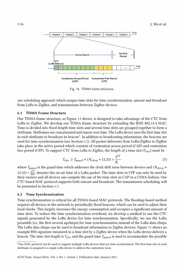
6.1 TDMA Frame StructureOur TDMA frame structure, as Figure 14 shows, is designed to take advantage of the CTC fromLoRa to ZigBee. We develop our TDMA frame structure by extending the IEEE 802.15.4 MAC.Time is divided into fixed-length time slots and several time slots are grouped together to form aslotframe. Slotframes are concatenated and repeat over time. The LoRa device uses the first time slotin each slotframe to broadcast its beacon5. In addition to broadcasting information, the beacons areused for time synchronization (see Section 6.2). All packet deliveries from LoRa/ZigBee to ZigBeetake place in the active period which consists of contention access period (CAP) and contentionfree period (CFP). To support CTC from LoRa to ZigBee, the length of a time slot (𝑇𝑠𝑙𝑜𝑡 ) must be
𝑇𝑠𝑙𝑜𝑡 ≥ 𝑇𝑔𝑢𝑎𝑟𝑑 + (𝑁𝑐ℎ𝑖𝑟𝑝 + 12.25) ∗ 2𝑆𝐹
𝐵𝑊(7)
where 𝑇𝑔𝑢𝑎𝑟𝑑 is the guard time which addresses the clock drift issue between devices and (𝑁𝑐ℎ𝑖𝑟𝑝 +12.25) ∗ 2𝑆𝐹
𝐵𝑊denotes the on-air time of a LoRa packet. The time slots in CFP can only be used by
their owners and all devices can compete the use of the time slots in CAP in a CSMA fashion. OurCTC-based MAC protocol supports both unicast and broadcast. The transmission scheduling willbe presented in Section 6.3.
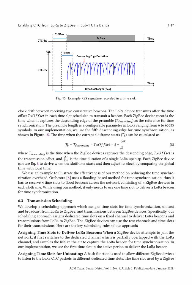
6.2 Time SynchronizationTime synchronization is critical for all TDMA-based MAC protocols. The flooding-based methodrequires all devices in the network to periodically flood beacons, which can be used to adjust theirlocal clocks. This largely increases the energy consumption and occupies a significant amount oftime slots. To reduce the time synchronization overhead, we develop a method to use the CTCsignals generated by the LoRa device for time synchronization. Specifically, we use the LoRapreamble (i.e. the first several upchirps) for time synchronization instead of the LoRa data chirps.The LoRa data chirps can be used to broadcast information to ZigBee devices. Figure 15 shows anexample RSS signature measured in a time slot by a ZigBee device when the LoRa device delivers abeacon. The time slot length is 𝑇𝑠𝑙𝑜𝑡 and the guard time 𝑇𝑔𝑢𝑎𝑟𝑑 is used to accommodate the possible
5Our MAC protocol can be used to support multiple LoRa devices that are time-synchronized. The first time slot in eachslotframe is assigned to a single LoRa device to address the contention issue.
ACM Trans. Sensor Netw., Vol. 1, No. 1, Article 1. Publication date: January 2021.
Enabling CTC from LoRa to ZigBee in Sub-1 GHz Bands 1:17
Fig. 15. Example RSS signature recorded in a time slot.
clock drift between receiving two consecutive beacons. The LoRa device transmits after the timeoffset 𝑇𝑥𝑂𝑓 𝑓 𝑠𝑒𝑡 in each time slot scheduled to transmit a beacon. Each ZigBee device records thetime when it captures the descending edge of the preamble (𝑇𝑑𝑒𝑠𝑐𝑒𝑛𝑑𝑖𝑛𝑔) as the reference for timesynchronization. The preamble length is a configurable parameter in LoRa ranging from 6 to 65535symbols. In our implementation, we use the fifth descending edge for time synchronization, asshown in Figure 15. The time when the current slotframe starts (𝑇𝑏 ) can be calculated as:
𝑇𝑏 = 𝑇𝑑𝑒𝑠𝑐𝑒𝑛𝑑𝑖𝑛𝑔 −𝑇𝑥𝑂𝑓 𝑓 𝑠𝑒𝑡 − 5 ∗ 2𝑆𝐹
𝐵𝑊(8)
where 𝑇𝑑𝑒𝑠𝑐𝑒𝑛𝑑𝑖𝑛𝑔 is the time when the ZigBee devices captures the descending edge, 𝑇𝑥𝑂𝑓 𝑓 𝑠𝑒𝑡 isthe transmission offset, and 2𝑆𝐹
𝐵𝑊is the time duration of a single LoRa upchirp. Each ZigBee device
can use Eq. 8 to derive when the slotframe starts and then adjust its clock by comparing the globaltime with local time.We use an example to illustrate the effectiveness of our method on reducing the time synchro-
nization overhead. Orchestra [8] uses a flooding-based method for time synchronization, thus ithas to reserve 𝑛 time slots to flood beacons across the network consisting of 𝑛 ZigBee devices ineach slotframe. While using our method, it only needs to use one time slot to deliver a LoRa beaconfor time synchronization.
6.3 Transmission SchedulingWe develop a scheduling approach which assigns time slots for time synchronization, unicastand broadcast from LoRa to ZigBee, and transmissions between ZigBee devices. Specifically, ourscheduling approach assigns dedicated time slots on a fixed channel to deliver LoRa beacons andtransmissions from LoRa to ZigBee. The ZigBee devices can use the rest channels and time slotsfor their transmissions. Here are the key scheduling rules of our approach:
Assigning Time Slots to Deliver LoRa Beacons: When a ZigBee device attempts to join thenetwork, it first switches to the dedicated channel which is partially overlapped with the LoRachannel, and samples the RSS in the air to capture the LoRa beacon for time synchronization. Inour implementation, we use the first time slot in the active period to deliver the LoRa beacon.
Assigning Time Slots for Unicasting: A hash function is used to allow different ZigBee devicesto listen to the LoRa CTC packets in different dedicated time slots. The time slot used by a ZigBee
ACM Trans. Sensor Netw., Vol. 1, No. 1, Article 1. Publication date: January 2021.
1:18 J. Shi et al.
Fig. 16. Variations of measured RSS signature features from the median value. 𝑣𝑎𝑟 (𝑁 ) = 2.
device to receive CTC is determined by its unique node id (𝐼𝐷). The LoRa device uses the 𝑠th timeslot to send information to the ZigBee device with 𝐼𝐷 :
𝑠 = (𝐼𝐷 − 𝐼𝐷𝑚𝑖𝑛)%(𝐶𝐹𝑃𝑒𝑛𝑑 −𝐶𝐹𝑃𝑏𝑒𝑔𝑖𝑛 + 1) +𝐶𝐹𝑃𝑏𝑒𝑔𝑖𝑛 (9)
where 𝐶𝐹𝑃𝑏𝑒𝑔𝑖𝑛 is the slot number of the first time slot in CFP, 𝐶𝐹𝑃𝑒𝑛𝑑 is the slot number of thelast time slot in CFP, and 𝐼𝐷𝑚𝑖𝑛 is the minimal node id in the network. We only use the CFP timeslots for CTC unicast.
Assigning Time Slots for Broadcasting: The last time slot in CFP is reserved for broadcast. AllZigbee devices can switch to the dedicated channel and wake up at the same time to receive CTCsignals broadcasted by the LoRa device.
Assigning Time Slots for ZigBee Transmissions: The ZigBee devices use the rest channelsfor transmission between them. During CAP time slots, all ZigBee devices compete for channelaccess in a CSMA fashion. The unoccupied CFP time slots can also be used for contention-freecommunication.
7 EVALUATIONTo validate the efficiency of our LoRaBee in enabling the CTC from LoRa to ZigBee, we performa series of experiments. We first perform microbenchmark experiments to validate our designand evaluate the capability of LoRaBee to effectively identify the best LoRa configuration, whichprovides the maximum throughput. We also evaluate the efficiency of LoRaBee’s encoding anddecoding processes. We then perform experiments to quantify the bit error rate (BER) of LoRaBeeunder different link distances in indoor and outdoor environments and repeat the experimentsunder controlled interference. Then, we study the impact of retransmissions on LoRaBee.
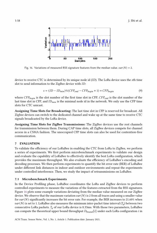
7.1 Microbenchmark ExperimentsIn the Device Profiling phase, LoRaBee coordinates the LoRa and ZigBee devices to performcontrolled experiments to measure the variations of the features extracted from the RSS signatures.Figure 16 plots some example variations deviating from the median value measured on our ZigBeedevice. We observe that the maximum variation 𝑣𝑎𝑟 (𝑁 ) is 2 from all traces and using a smaller valuefor 𝑣𝑎𝑟 (𝑁 ) significantly increases the bit error rate. For example, the BER increases to 21.60% when𝑣𝑎𝑟 (𝑁 ) is set to 1. LoRaBee also measures the minimum inter-packet time interval (𝑇𝑔) between twoconsecutive LoRa packets. 𝑇𝑔 of our LoRa device is 8.33ms. With those two parameters, LoRaBeecan compute the theoretical upper bound throughput 𝐷𝑏𝑜𝑢𝑛𝑑 [𝑖] under each LoRa configuration 𝑖 in
ACM Trans. Sensor Netw., Vol. 1, No. 1, Article 1. Publication date: January 2021.
Enabling CTC from LoRa to ZigBee in Sub-1 GHz Bands 1:19
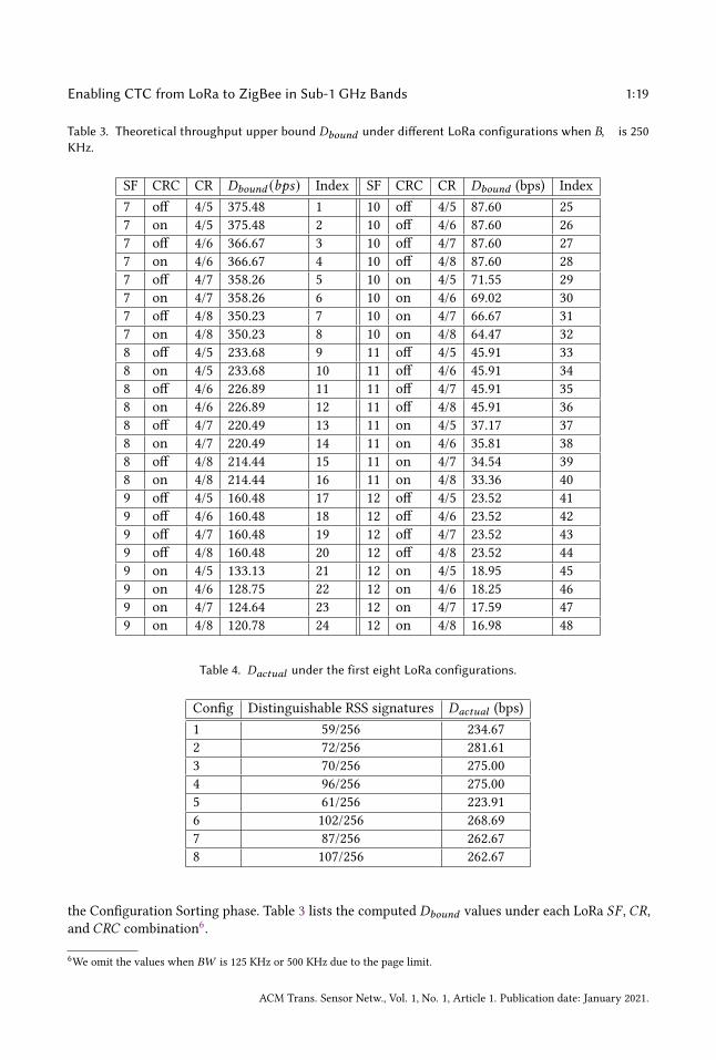
Table 3. Theoretical throughput upper bound 𝐷𝑏𝑜𝑢𝑛𝑑 under different LoRa configurations when 𝐵𝑊 is 250KHz.
SF CRC CR 𝐷𝑏𝑜𝑢𝑛𝑑 (𝑏𝑝𝑠) Index SF CRC CR 𝐷𝑏𝑜𝑢𝑛𝑑 (bps) Index7 off 4/5 375.48 1 10 off 4/5 87.60 257 on 4/5 375.48 2 10 off 4/6 87.60 267 off 4/6 366.67 3 10 off 4/7 87.60 277 on 4/6 366.67 4 10 off 4/8 87.60 287 off 4/7 358.26 5 10 on 4/5 71.55 297 on 4/7 358.26 6 10 on 4/6 69.02 307 off 4/8 350.23 7 10 on 4/7 66.67 317 on 4/8 350.23 8 10 on 4/8 64.47 328 off 4/5 233.68 9 11 off 4/5 45.91 338 on 4/5 233.68 10 11 off 4/6 45.91 348 off 4/6 226.89 11 11 off 4/7 45.91 358 on 4/6 226.89 12 11 off 4/8 45.91 368 off 4/7 220.49 13 11 on 4/5 37.17 378 on 4/7 220.49 14 11 on 4/6 35.81 388 off 4/8 214.44 15 11 on 4/7 34.54 398 on 4/8 214.44 16 11 on 4/8 33.36 409 off 4/5 160.48 17 12 off 4/5 23.52 419 off 4/6 160.48 18 12 off 4/6 23.52 429 off 4/7 160.48 19 12 off 4/7 23.52 439 off 4/8 160.48 20 12 off 4/8 23.52 449 on 4/5 133.13 21 12 on 4/5 18.95 459 on 4/6 128.75 22 12 on 4/6 18.25 469 on 4/7 124.64 23 12 on 4/7 17.59 479 on 4/8 120.78 24 12 on 4/8 16.98 48
Table 4. 𝐷𝑎𝑐𝑡𝑢𝑎𝑙 under the first eight LoRa configurations.
Config Distinguishable RSS signatures 𝐷𝑎𝑐𝑡𝑢𝑎𝑙 (bps)1 59/256 234.672 72/256 281.613 70/256 275.004 96/256 275.005 61/256 223.916 102/256 268.697 87/256 262.678 107/256 262.67
the Configuration Sorting phase. Table 3 lists the computed 𝐷𝑏𝑜𝑢𝑛𝑑 values under each LoRa 𝑆𝐹 ,𝐶𝑅,and 𝐶𝑅𝐶 combination6.
6We omit the values when 𝐵𝑊 is 125 KHz or 500 KHz due to the page limit.
ACM Trans. Sensor Netw., Vol. 1, No. 1, Article 1. Publication date: January 2021.
1:20 J. Shi et al.
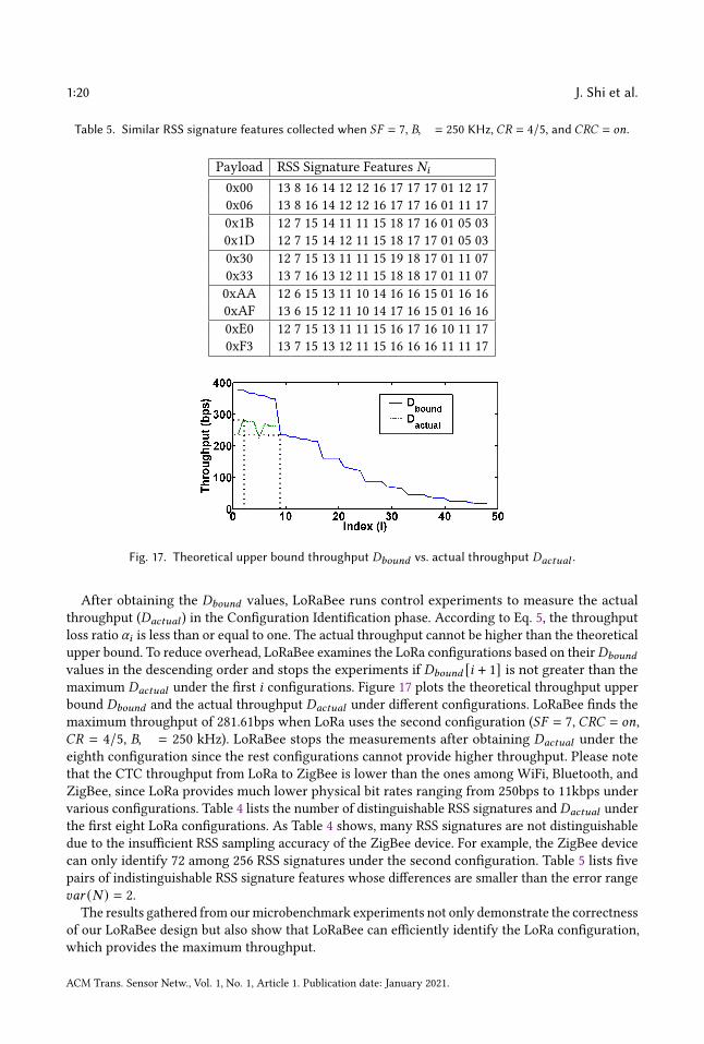
Table 5. Similar RSS signature features collected when 𝑆𝐹 = 7, 𝐵𝑊 = 250 KHz, 𝐶𝑅 = 4/5, and 𝐶𝑅𝐶 = 𝑜𝑛.
Payload RSS Signature Features 𝑁𝑖
0x00 13 8 16 14 12 12 16 17 17 17 01 12 170x06 13 8 16 14 12 12 16 17 17 16 01 11 170x1B 12 7 15 14 11 11 15 18 17 16 01 05 030x1D 12 7 15 14 12 11 15 18 17 17 01 05 030x30 12 7 15 13 11 11 15 19 18 17 01 11 070x33 13 7 16 13 12 11 15 18 18 17 01 11 070xAA 12 6 15 13 11 10 14 16 16 15 01 16 160xAF 13 6 15 12 11 10 14 17 16 15 01 16 160xE0 12 7 15 13 11 11 15 16 17 16 10 11 170xF3 13 7 15 13 12 11 15 16 16 16 11 11 17
Fig. 17. Theoretical upper bound throughput 𝐷𝑏𝑜𝑢𝑛𝑑 vs. actual throughput 𝐷𝑎𝑐𝑡𝑢𝑎𝑙 .
After obtaining the 𝐷𝑏𝑜𝑢𝑛𝑑 values, LoRaBee runs control experiments to measure the actualthroughput (𝐷𝑎𝑐𝑡𝑢𝑎𝑙 ) in the Configuration Identification phase. According to Eq. 5, the throughputloss ratio 𝛼𝑖 is less than or equal to one. The actual throughput cannot be higher than the theoreticalupper bound. To reduce overhead, LoRaBee examines the LoRa configurations based on their𝐷𝑏𝑜𝑢𝑛𝑑
values in the descending order and stops the experiments if 𝐷𝑏𝑜𝑢𝑛𝑑 [𝑖 + 1] is not greater than themaximum 𝐷𝑎𝑐𝑡𝑢𝑎𝑙 under the first 𝑖 configurations. Figure 17 plots the theoretical throughput upperbound 𝐷𝑏𝑜𝑢𝑛𝑑 and the actual throughput 𝐷𝑎𝑐𝑡𝑢𝑎𝑙 under different configurations. LoRaBee finds themaximum throughput of 281.61bps when LoRa uses the second configuration (𝑆𝐹 = 7, 𝐶𝑅𝐶 = 𝑜𝑛,𝐶𝑅 = 4/5, 𝐵𝑊 = 250 kHz). LoRaBee stops the measurements after obtaining 𝐷𝑎𝑐𝑡𝑢𝑎𝑙 under theeighth configuration since the rest configurations cannot provide higher throughput. Please notethat the CTC throughput from LoRa to ZigBee is lower than the ones among WiFi, Bluetooth, andZigBee, since LoRa provides much lower physical bit rates ranging from 250bps to 11kbps undervarious configurations. Table 4 lists the number of distinguishable RSS signatures and 𝐷𝑎𝑐𝑡𝑢𝑎𝑙 underthe first eight LoRa configurations. As Table 4 shows, many RSS signatures are not distinguishabledue to the insufficient RSS sampling accuracy of the ZigBee device. For example, the ZigBee devicecan only identify 72 among 256 RSS signatures under the second configuration. Table 5 lists fivepairs of indistinguishable RSS signature features whose differences are smaller than the error range𝑣𝑎𝑟 (𝑁 ) = 2.
The results gathered from ourmicrobenchmark experiments not only demonstrate the correctnessof our LoRaBee design but also show that LoRaBee can efficiently identify the LoRa configuration,which provides the maximum throughput.
ACM Trans. Sensor Netw., Vol. 1, No. 1, Article 1. Publication date: January 2021.
Enabling CTC from LoRa to ZigBee in Sub-1 GHz Bands 1:21
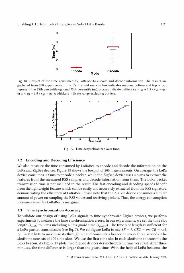
Fig. 18. Boxplot of the time consumed by LoRaBee to encode and decode information. The results aregathered from 200 experimental runs. Central red mark in box indicates median; bottom and top of boxrepresent the 25th percentile (𝑞1) and 75th percentile (𝑞2); crosses indicate outliers (𝑥 > 𝑞2 + 1.5 ∗ (𝑞2 − 𝑞1)or 𝑥 < 𝑞1 − 1.5 ∗ (𝑞2 − 𝑞1)); whiskers indicate range excluding outliers.
Fig. 19. Time desynchronized over time.
7.2 Encoding and Decoding EfficiencyWe also measure the time consumed by LoRaBee to encode and decode the information on theLoRa and ZigBee devices. Figure 18 shows the boxplot of 200 measurements. On average, the LoRadevice consumes 0.33ms to encode a packet, while the ZigBee device uses 4.66ms to extract thefeatures from the measured RSS samples and decode information from them. The LoRa packettransmission time is not included in the result. The fast encoding and decoding speeds benefitfrom the lightweight feature which can be easily and accurately extracted from the RSS signature,demonstrating the efficiency of LoRaBee. Please note that the ZigBee device consumes a similaramount of power on sampling the RSS values and receiving packets. Thus, the energy consumptionincrease caused by LoRaBee is marginal.
7.3 Time Synchronization AccuracyTo validate our design of using LoRa signals to time synchronize ZigBee devices, we performexperiments to measure the time synchronization errors. In our experiments, we set the time slotlength (𝑇𝑠𝑙𝑜𝑡 ) to 30ms including a 3ms guard time (𝑇𝑔𝑢𝑎𝑟𝑑 ). The time slot length is sufficient fora LoRa packet transmission (see Eq. 7). We configure LoRa to use 𝑆𝐹 = 7, 𝐶𝑅𝐶 = 𝑜𝑛, 𝐶𝑅 = 4/5,𝐵𝑊 = 250 kHz to maximize its throughput and transmits a beacon in every three seconds. Theslotframe consists of 100 time slots. We use the first time slot in each slotframe to transmit theLoRa beacon. As Figure 19 plots, two ZigBee devices desynchronize in time very fast. After threeminutes, the time difference is larger than the guard time. With the help of LoRa beacons, the
ACM Trans. Sensor Netw., Vol. 1, No. 1, Article 1. Publication date: January 2021.
1:22 J. Shi et al.
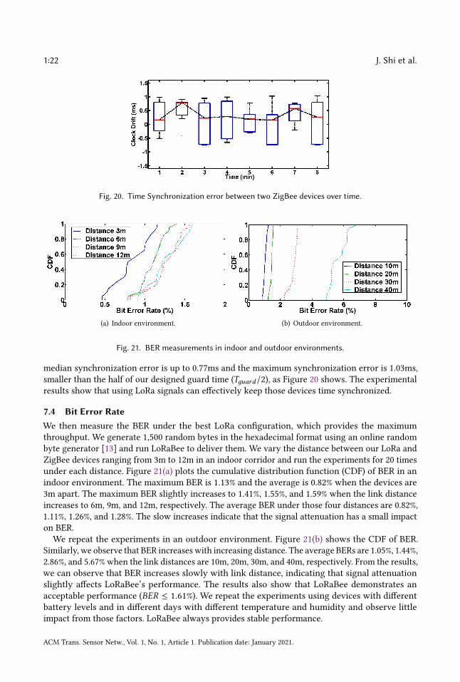
Fig. 20. Time Synchronization error between two ZigBee devices over time.
(a) Indoor environment. (b) Outdoor environment.
Fig. 21. BER measurements in indoor and outdoor environments.
median synchronization error is up to 0.77ms and the maximum synchronization error is 1.03ms,smaller than the half of our designed guard time (𝑇𝑔𝑢𝑎𝑟𝑑/2), as Figure 20 shows. The experimentalresults show that using LoRa signals can effectively keep those devices time synchronized.
7.4 Bit Error RateWe then measure the BER under the best LoRa configuration, which provides the maximumthroughput. We generate 1,500 random bytes in the hexadecimal format using an online randombyte generator [13] and run LoRaBee to deliver them. We vary the distance between our LoRa andZigBee devices ranging from 3m to 12m in an indoor corridor and run the experiments for 20 timesunder each distance. Figure 21(a) plots the cumulative distribution function (CDF) of BER in anindoor environment. The maximum BER is 1.13% and the average is 0.82% when the devices are3m apart. The maximum BER slightly increases to 1.41%, 1.55%, and 1.59% when the link distanceincreases to 6m, 9m, and 12m, respectively. The average BER under those four distances are 0.82%,1.11%, 1.26%, and 1.28%. The slow increases indicate that the signal attenuation has a small impacton BER.We repeat the experiments in an outdoor environment. Figure 21(b) shows the CDF of BER.
Similarly, we observe that BER increases with increasing distance. The average BERs are 1.05%, 1.44%,2.86%, and 5.67% when the link distances are 10m, 20m, 30m, and 40m, respectively. From the results,we can observe that BER increases slowly with link distance, indicating that signal attenuationslightly affects LoRaBee’s performance. The results also show that LoRaBee demonstrates anacceptable performance (𝐵𝐸𝑅 ≤ 1.61%). We repeat the experiments using devices with differentbattery levels and in different days with different temperature and humidity and observe littleimpact from those factors. LoRaBee always provides stable performance.
ACM Trans. Sensor Netw., Vol. 1, No. 1, Article 1. Publication date: January 2021.
Enabling CTC from LoRa to ZigBee in Sub-1 GHz Bands 1:23
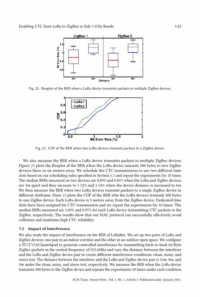
Fig. 22. Boxplot of the BER when a LoRa device transmits packets to multiple ZigBee devices.
Fig. 23. CDF of the BER when two LoRa devices transmit packets to a ZigBee device.
We also measure the BER when a LoRa device transmits packets to multiple ZigBee devices.Figure 22 plots the Boxplot of the BER when the LoRa device unicasts 500 bytes to two ZigBeedevices three or six meters away. We schedule the CTC transmissions to use two different timeslots based on our scheduling rules specified in Section 6.3 and repeat the experiments for 10 times.The median BERs measured on two devices are 0.89% and 0.83% when the LoRa and ZigBee devicesare 3𝑚 apart and they increase to 1.12% and 1.14% when the device distance is increased to 6𝑚.We then measure the BER when two LoRa devices transmit packets to a single ZigBee device indifferent slotframe. Fiure 23 plots the CDF of the BER whe the LoRa devices transmit 500 bytesto one ZigBee device. Each LoRa device is 3 meters away from the ZigBee device. Dedicated timeslots have been assigned for CTC transmission and we repeat the experiments for 10 times. Themedian BERs measured are 1.05% and 0.97% for each LoRa device transmitting CTC packets to theZigBee, respectively. The results show that our MAC protocol can successfully effectively avoidcollisions and maintains high CTC reliability.
7.5 Impact of InterferenceWe also study the impact of interference on the BER of LoRaBee. We set up two pairs of LoRa andZigBee devices: one pair in an indoor corridor and the other in an outdoor open space. We configurea TI CC1310 launchpad to generate controlled interference by transmitting back-to-back 64-ByteZigBee packets in the central frequency of 915.6Mhz and vary the distance between the interfererand the LoRa and ZigBee device pair to create different interference conditions: clean, noisy, andstress test. The distance between the interferer and the LoRa and ZigBee device pair is 15𝑚, 8𝑚, and5𝑚 under the clean, noisy, and stress test, respectively. We measure the BER when the LoRa devicetransmits 500 bytes to the ZigBee device and repeats the experiments 10 times under each condition.
ACM Trans. Sensor Netw., Vol. 1, No. 1, Article 1. Publication date: January 2021.

1:24 J. Shi et al.
Fig. 24. Box plot of the BER of LoRaBee in the clean, noisy, and stress testing environments.
(a) Reliability. (b) Throughput.
Fig. 25. Performance with different No. of transmission attempts per packet.
Figure 24 shows the Boxplot of BER when the LoRa and ZigBee devices are three meter away.In the indoor environment, LoRaBee achieves median BERs of 0.67%, 1.72%, and 15.10% in clean,noisy, and stress test environments, respectively. In the outdoor environment, LoRaBee achievesmedian BERs of 0.54%, 1.66%, and 12.28% in clean, noisy, and stress test environments, respectively.The results show that LoRaBee consistently provides low BERs under moderate interference. Thesignificant increases on BERs under strong interference emphasize the importance of employingan appropriate medium access control (MAC) protocol (e.g., a TDMA-based MAC) when usingLoRaBee.
7.6 Impact of RetransmissionsTo evaluate the impact of retransmissions on LoRaBee, we have performed the experiments withdifferent number of transmission attempts. Figure 25(b) shows the performance of LoRaBee with dif-ferent number of transmission attempts per packet when the devices are 6m apart in the corridor. AsFigure 25(a) shows, the retransmissions successfully improve the median packet delivery ratio (PDR)from 81.54% to 100% when three transmission attempts are scheduled for each packet. All PDRsbecome 100% when four transmission attempts are scheduled for each packet. As Figure 25(b), thethroughput decreases with more transmission attempts. The results show that the retransmissionseffectively enhance the link reliability at the cost of reduced throughput.
8 CONCLUSIONSIn this paper, we present LoRaBee, a novel CTC approach to enable the direct communication fromLoRa to ZigBee. By elaborately tuning the LoRa’s central carrier frequency and packet payload, a
ACM Trans. Sensor Netw., Vol. 1, No. 1, Article 1. Publication date: January 2021.
Enabling CTC from LoRa to ZigBee in Sub-1 GHz Bands 1:25
ZigBee device can decode the LoRa chirps by simply sensing the RSS. An empirical study has beenperformed to investigate the characteristics of LoRa communication from a CTC’s point of viewand a series of insights are distilled to guide our LoRaBee design. LoRaBee has been implementedand tested on real hardware. Experimental results show that our LoRaBee provides reliable CTCcommunication from LoRa to ZigBee with the throughput of up to 281.61bps in the Sub-1 GHzbands in indoor and outdoor environments, which is enough for a LoRa base station to disseminatenetwork management and urgent control messages to ZigBee devices, such as the periodic networkmanagement beacons transmitted by Orchestra [8] and the control messages generated by thecoupled water tank monitoring system [21].
ACKNOWLEDGMENTThis work was supported in part by the National Science Foundation under grants CNS-1657275and CNS-2046538.
REFERENCES[1] 802.15.4e. 2020. IEEE 802.15.4e WPAN Task Group. http://www.ieee802.org/15/pub/TG4e.html[2] Bluetooth. 1998. Bluetooth Technology. https://www.bluetooth.com/[3] businesswire. 2017. Multi-Band IoT Mesh Network Technology for Massive IoT
Deployments. https://www.businesswire.com/news/home/20170621005029/en/The-Zigbee-Alliance-Introduces-First-Multi-Band-IoT-Mesh-Network-Technology-for-Massive-IoT-Deployments
[4] CC1310. 2018. CC1310. http://www.ti.com/lit/ds/symlink/cc1310.pdf[5] K. Chebrolu and A. Dhekne. 2009. Esense: Communication through Energy Sensing. In Annual International Conference
on Mobile Computing and Networking (MobiCom). Association for Computing Machinery, New York, NY, USA, 85–96.[6] Zicheng Chi, Yan Li, Hongyu Sun, Yao Yao, Zheng Lu, and Ting Zhu. 2016. B2W2: N-Way Concurrent Communication
for IoT Devices. In Proceedings of the 14th ACM Conference on Embedded Network Sensor Systems CD-ROM (SenSys ’16).Association for Computing Machinery, New York, NY, USA, 245–258. https://doi.org/10.1145/2994551.2994561
[7] Semtech Corporation. 1960. Semtech. https://www.semtech.com/[8] Simon Duquennoy, Beshr Al Nahas, Olaf Landsiedel, and Thomas Watteyne. 2015. Orchestra: Robust Mesh Networks
Through Autonomously Scheduled TSCH. In Sensys. Association for Computing Machinery, New York, NY, USA,337–350.
[9] Piotr Gawlowicz, Anatolij Zubow, and Adam Wolisz. 2018. Enabling Cross-technology Communication between LTEUnlicensed and WiFi. In IEEE International Conference on Computer Communications (INFOCOM). IEEE, Honolulu, HI,USA, 144–152.
[10] Chaojie Gu, Rui Tan, and Xin Lou. 2019. One-Hop Out-of-Band Control Planes for Multi-HopWireless Sensor Networks.ACM Transaction on Sensor Network 15, 4 (July 2019), 29. https://doi.org/10.1145/3342100
[11] Xiuzhen Guo, Yuan He, Xiaolong Zheng, Liangcheng Yu, and Omprakash Gnawali. 2018. ZIGFI: Harnessing ChannelState Information for Cross-Technology Communication. In IEEE International Conference on Computer Communications(INFOCOM). IEEE, Honolulu, HI, USA, 360–368.
[12] Xiuzhen Guo, Xiaolong Zheng, and Yuan He. 2017. WiZig: Cross-Technology Energy Communication over a NoisyChannel. In IEEE International Conference on Computer Communications (INFOCOM). IEEE, Atlanta, GA, USA, 1–9.
[13] Mads Haahr. 1998. Random.org. https://www.random.org/bytes/[14] Cooking Hacks. 2016. SX1272 LoRa Shield for Raspberry Pi. https://www.cooking-hacks.com/
sx1272-lora-shield-for-raspberry-pi-900-mhz[15] Richard Wesley Hamming. 1950. Error Detecting and Error Correcting Codes. Bell System Technical Journal 2, 29
(1950), 147–160.[16] T. Hao, R. Zhou, G. Xing, M. W. Mutka, and J. Chen. 2014. WizSync: Exploiting Wi-Fi Infrastructure for Clock
Synchronization in Wireless Sensor Networks. IEEE Transactions on Mobile Computing 13, 6 (June 2014), 1379–1392.[17] Wenchao Jiang, Song Min Kim, Zhijun Li, and Tian He. 2018. Achieving Receiver-Side Cross-Technology Com-
munication with Cross-Decoding. In Proceedings of the 24th Annual International Conference on Mobile Comput-ing and Networking (MobiCom ’18). Association for Computing Machinery, New York, NY, USA, 639–652. https://doi.org/10.1145/3241539.3241547
[18] Song Min Kim and Tian He. 2015. Freebee: Cross-Technology Communication via Free Side-Channel. In AnnualInternational Conference on Mobile Computing and Networking (MobiCom). Association for Computing Machinery, NewYork, NY, USA, 317–330.
ACM Trans. Sensor Netw., Vol. 1, No. 1, Article 1. Publication date: January 2021.

1:26 J. Shi et al.
[19] S. M. Kim, S. Ishida, S. Wang, and T. He. 2017. Free Side-Channel Cross-Technology Communication in WirelessNetworks. IEEE/ACM Transactions on Networking 25, 5 (2017), 2974–2987.
[20] Silicon Labs. 2017. Silicon Labs EFR32MG12P433F1024GM48. https://www.silabs.com/products/wireless/mesh-networking/efr32mg-mighty-gecko-zigbee-thread-soc/device.efr32mg12p433f1024gm48
[21] Bo Li, Lanshun Nie, Chengjie Wu, Humberto Gonzalez, and Chenyang Lu. 2015. Incorporating Emergency Alarms inReliableWireless Process Control. InACM/IEEE International Conference on Cyber-Physical Systems (ICCPS). Associationfor Computing Machinery, New York, NY, USA, 218–227.
[22] Zhijun Li and Tian He. 2017. WEBee: Physical-Layer Cross-Technology Communication via Emulation. In AnnualInternational Conference on Mobile Computing and Networking (MobiCom). Association for Computing Machinery, NewYork, NY, USA, 2–14.
[23] LoRa. 2015. LoRa Alliance. https://lora-alliance.org/[24] Chenyang Lu, Abusayeed Saifullah, Bo Li, Mo Sha, Humberto Gonzalez, Dolvara Gunatilaka, Chengjie Wu, Lanshun
Nie, and Yixin Chen. 2016. Real-Time Wireless Sensor-Actuator Networks for Industrial Cyber-Physical Systems.Proceedings of the IEEE, Special Issue on Industrial Cyber Physical Systems 104, 5 (2016), 1013–1024.
[25] Microchip. 2015. RN2903. http://ww1.microchip.com/downloads/en/DeviceDoc/50002390E.pdf[26] Raspberry Pi. 2016. Raspberry Pi 3 Model B. https://www.raspberrypi.org/products/raspberry-pi-3-model-b/[27] Michael E Porter and James E Heppelmann. 2014. How Smart, Connected Products Are Transforming Competition.
Harvard Business Review 92, 11 (2014), 64–88.[28] Junyang Shi, Xingjian Chen, and Mo Sha. 2019. Enabling Direct Messaging from LoRa to ZigBee in the 2.4 GHz Band
for Industrial Wireless Networks. In 2019 IEEE International Conference on Industrial Internet (ICII). IEEE, Orlando, FL,USA, 180–189.
[29] Junyang Shi, Di Mu, and Mo Sha. 2019. LoRaBee: Cross-Technology Communication from LoRa to ZigBee via PayloadEncoding. In 2019 IEEE 27th International Conference on Network Protocols (ICNP). IEEE, Chicago, IL, USA, USA, 1–11.
[30] TICC1352R. 2018. TI CC1352R LaunchPad. http://www.ti.com/tool/launchxl-cc1352r1[31] H. Wang and A. O. Fapojuwo. 2017. A Survey of Enabling Technologies of Low Power and Long Range Machine-to-
Machine Communications. IEEE Communications Surveys Tutorials 19, 4 (2017), 2621–2639.[32] Shuai Wang, Woojae Jeong, Jinhwan Jung, and Song Min Kim. 2020. X-MIMO: Cross-Technology Multi-User MIMO.
In Proceedings of the 18th Conference on Embedded Networked Sensor Systems (SenSys). ACM, New York, NY, USA,218–231.
[33] S. Wang, S. M. Kim, and T. He. 2018. Symbol-Level Cross-Technology Communication via Payload Encoding. In IEEEInternational Conference on Distributed Computing Systems (ICDCS). IEEE, Vienna, Austria, 500–510.
[34] S. Wang, Z. Yin, S. M. Kim, and T. He. 2017. Achieving Spectrum Efficient Communication under Cross-TechnologyInterference. In International Conference on Computer Communication and Networks (ICCCN). IEEE, Vancouver, BC,Canada, 1–8.
[35] WiFi. 2000. WiFi Alliance. https://www.wi-fi.org/[36] Dan Xia, Xiaolong Zheng, Liang Liu, Chaoyu Wang, and Huadong Ma. 2020. c-Chirp: Towards Symmetric Cross-
technology Communication over Asymmetric Channels. In IEEE International Conference on Sensing, Communication,and Networking (SECON). IEEE, Como, Italy, 1–9.
[37] S. Yin, Q. Li, and O. Gnawali. 2015. Interconnecting WiFi Devices with IEEE 802.15.4 Devices without Using a Gateway.In International Conference on Distributed Computing in Sensor Systems (DCOSS). IEEE, Fortaleza, Brazil, 127–136.
[38] Zhimeng Yin, Wenchao Jiang, Song Min Kim, and Tian He. 2017. C-Morse: Cross-Technology Communication withTransparent Morse Coding. In IEEE International Conference on Computer Communications (INFOCOM). IEEE, Atlanta,GA, USA, 1–9.
[39] Zihao Yu, Chengkun Jiang, Yuan He, Xiaolong Zheng, and Xiuzhen Guo. 2018. Crocs: Cross-Technology ClockSynchronization for WiFi and ZigBee. In Proceedings of the 2018 International Conference on Embedded Wireless Systemsand Networks. Junction Publishing, USA, 135–144.
[40] Xinyu Zhang and Kang G. Shin. 2013. Cooperative Carrier Signaling: Harmonizing Coexisting WPAN and WLANDevices. IEEE/ACM Transactions on Networking 21, 2 (2013), 426–439. https://doi.org/10.1109/TNET.2012.2200499
[41] X. Zhang and K. G. Shin. 2013. Gap Sense: Lightweight Coordination of Heterogeneous Wireless Devices. In IEEEInternational Conference on Computer Communications (INFOCOM). IEEE, Turin, Italy, 3094–3101.
[42] Yifan Zhang and Qun Li. 2013. HoWiES: A Holistic Approach to ZigBee Assisted WiFi Energy Savings in MobileDevices. In IEEE International Conference on Computer Communications (INFOCOM). IEEE, Turin, Italy, 1366–1374.
[43] Xiaolong Zheng, Yuan He, and Xiuzhen Guo. 2018. StripComm: Interference-Resilient Cross-Technology Communica-tion in Coexisting Environments. In IEEE International Conference on Computer Communications (INFOCOM). IEEE,Honolulu, HI, USA, 171–179.
ACM Trans. Sensor Netw., Vol. 1, No. 1, Article 1. Publication date: January 2021.
Enabling CTC from LoRa to ZigBee in Sub-1 GHz Bands 1:27
[44] Xiaolong Zheng, Dan Xia, Xiuzhen Guo, Liang Liu, Yuan He, and Huadong Ma. 2020. Portal: Transparent Cross-Technology Opportunistic Forwarding for Low-Power Wireless Networks. In Proceedings of the Twenty-First Interna-tional Symposium on Theory, Algorithmic Foundations, and Protocol Design for Mobile Networks and Mobile Computing(Mobihoc). ACM, New York, NY, USA, 241–250.
[45] ZigBee. 2002. Zigbee Alliance. https://zigbeealliance.org/[46] ZigBee. 2017. Zigbee Alliance introduces Zigbee PRO 2017. https://www.automation.com/en-us/products/product03/
zigbee-alliance-introduces-zigbee-pro-2017[47] A. Zubow, P. Gawlowicz, and S. Bayhan. 2018. On Practical Coexistence Gaps in Space for LTE-U/WiFi Coexistence.
In European Wireless 2018; 24th European Wireless Conference. VDE, Catania, Italy, 1–8.
ACM Trans. Sensor Netw., Vol. 1, No. 1, Article 1. Publication date: January 2021.