Embed Size (px)
Citation preview
Copyright © 2000 Honeywell AG • All rights reserved EN0H-048GE25 R0700
V5032Kombi-2-plus
BALANCING AND SHUT-OFF VALVE
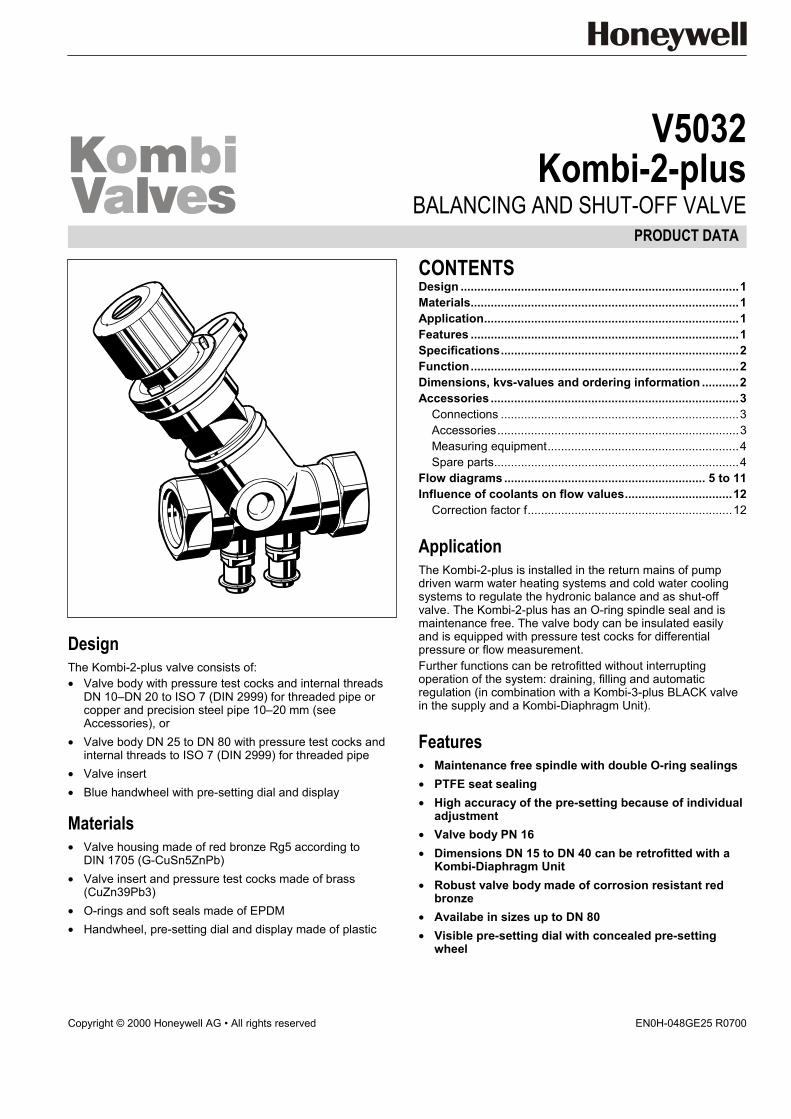
DesignThe Kombi-2-plus valve consists of:• Valve body with pressure test cocks and internal threads
DN 10–DN 20 to ISO 7 (DIN 2999) for threaded pipe orcopper and precision steel pipe 10–20 mm (seeAccessories), or
• Valve body DN 25 to DN 80 with pressure test cocks andinternal threads to ISO 7 (DIN 2999) for threaded pipe
• Valve insert• Blue handwheel with pre-setting dial and display
Materials• Valve housing made of red bronze Rg5 according to
DIN 1705 (G-CuSn5ZnPb)• Valve insert and pressure test cocks made of brass
(CuZn39Pb3)• O-rings and soft seals made of EPDM• Handwheel, pre-setting dial and display made of plastic
CONTENTSDesign ...................................................................................1Materials................................................................................1Application............................................................................1Features ................................................................................1Specifications.......................................................................2Function................................................................................2Dimensions, kvs-values and ordering information ...........2Accessories ..........................................................................3
Connections .......................................................................3Accessories........................................................................3Measuring equipment.........................................................4Spare parts.........................................................................4
Flow diagrams ............................................................ 5 to 11Influence of coolants on flow values................................12
Correction factor f.............................................................12
ApplicationThe Kombi-2-plus is installed in the return mains of pumpdriven warm water heating systems and cold water coolingsystems to regulate the hydronic balance and as shut-offvalve. The Kombi-2-plus has an O-ring spindle seal and ismaintenance free. The valve body can be insulated easilyand is equipped with pressure test cocks for differentialpressure or flow measurement.Further functions can be retrofitted without interruptingoperation of the system: draining, filling and automaticregulation (in combination with a Kombi-3-plus BLACK valvein the supply and a Kombi-Diaphragm Unit).
Features• Maintenance free spindle with double O-ring sealings• PTFE seat sealing• High accuracy of the pre-setting because of individual
adjustment• Valve body PN 16• Dimensions DN 15 to DN 40 can be retrofitted with a
Kombi-Diaphragm Unit• Robust valve body made of corrosion resistant red
bronze• Availabe in sizes up to DN 80• Visible pre-setting dial with concealed pre-setting
wheel
PRODUCT DATA
KOMBI-2-PLUS
EN0H-048GE25 R0700 2 Honeywell AG • All rights reserved
SpecificationsMedium Water, water-glycole mixtureOperating temperature 2 to 130 °C (36 to 266 °F)Operating pressure max. 16 bar (232 p.s.i.)Differential pressure max. 2,0 bar (29 p.s.i.) –
see NOTE belowkvs-values see table on page 2
NOTE: Differential pressure: Closing pressure forKombi-2-plus with installed Kombi-Diaphragm Unit.Regarding noise generation the conditions,requirements and installation design have to betaken into account.
FunctionThe hydronic balance is a significant requirement for theefficient operation of a hydronic heating or cooling installation.In an unbalanced system under or over provision of hot waterto individual radiators or circuits can occur. Apart from thecorrect selection of radiator valves, regulation of individualcircuits is also necessary and in some cases, such as inDIN 18 380, VOB part C, is required by national standards.This requirement is met with the shutoff and balancing valveKombi-2-plus. The Kombi-2-plus for the return has thefunctions shutoff, pre-setting, regulation (with diaphragm unit,accessory), draining and filling (draining adapter, accessory).
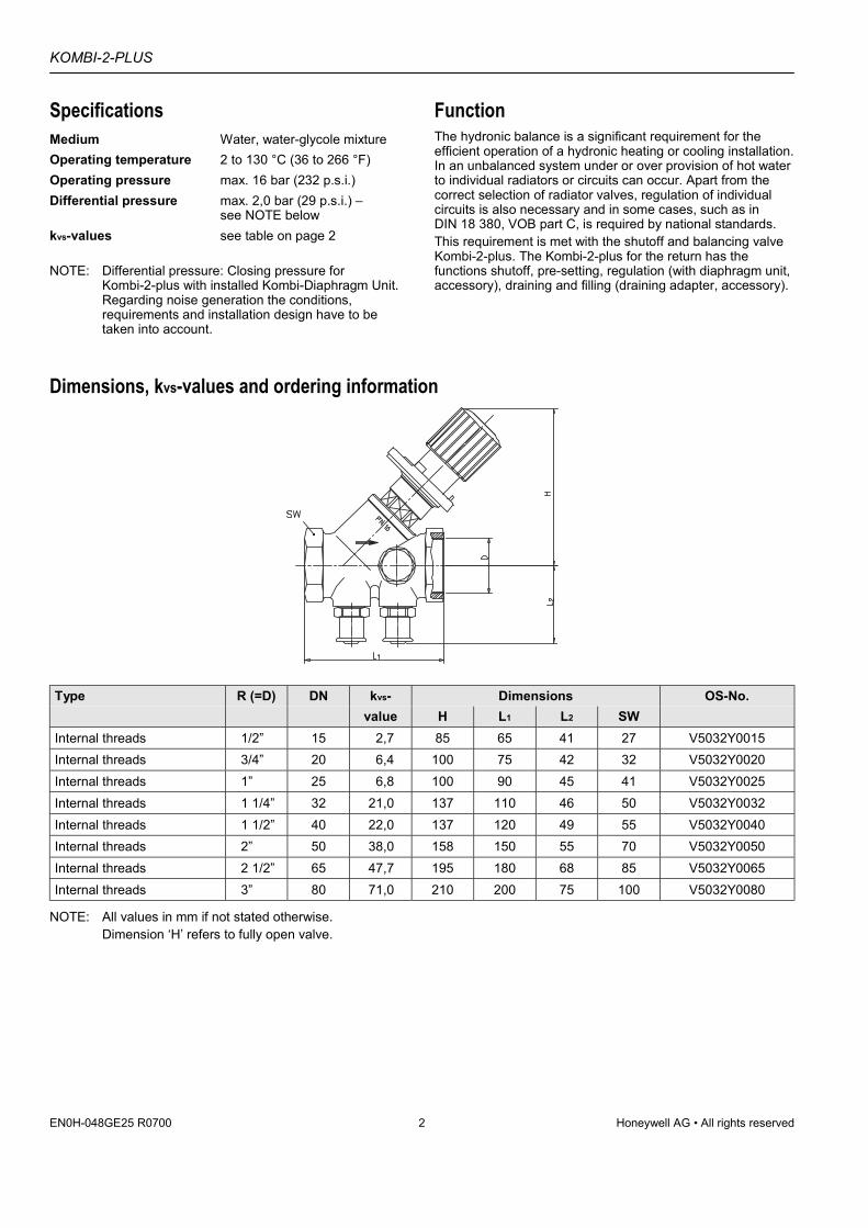
Dimensions, kvs-values and ordering information
Type R (=D) DN kvs- Dimensions OS-No.value H L1 L2 SW
Internal threads 1/2” 15 2,7 85 65 41 27 V5032Y0015Internal threads 3/4” 20 6,4 100 75 42 32 V5032Y0020Internal threads 1” 25 6,8 100 90 45 41 V5032Y0025Internal threads 1 1/4” 32 21,0 137 110 46 50 V5032Y0032Internal threads 1 1/2” 40 22,0 137 120 49 55 V5032Y0040Internal threads 2” 50 38,0 158 150 55 70 V5032Y0050Internal threads 2 1/2” 65 47,7 195 180 68 85 V5032Y0065Internal threads 3” 80 71,0 210 200 75 100 V5032Y0080
NOTE: All values in mm if not stated otherwise.Dimension ‘H’ refers to fully open valve.
KOMBI-2-PLUS
Honeywell AG • All rights reserved 3 EN0H-048GE25 R0700
AccessoriesConnectionsSet of compression ring and nut
1/2” x 10 mm 1 01 01 13 015 0001/2” x 12 mm 1 01 01 14 015 0001/2” x 14 mm 1 01 01 18 015 0001/2” x 15 mm 1 01 01 24 015 0001/2” x 16 mm 1 01 01 20 015 0003/4” x 18 mm 1 01 01 38 020 0003/4” x 22 mm 1 01 01 24 020 000
NOTE: For soft copper and steel pipe support inserts haveto be used.
Set of compression ring, nut and support insert (2 pcs each)
1/2” x 12 mm 1 01 01 35 120 0001/2” x 15 mm 1 01 01 35 150 0001/2” x 16 mm 1 01 01 35 160 0003/4” x 18 mm 1 01 01 36 180 000
AccessoriesKombi-Diaphragm Unit
Setting range 0,1 to 0,3bar differential pressure;for valves DN 15–DN 40
1 81 10 00 000 000
Setting range 0,3 to 0,6bar differential pressure;for valve DN 15–DN 40
1 81 30 00 000 000
NOTE: For product information and diagrams see productdata sheet ‘Kombi-Diaphragm Unit’.The Kombi-3-plus BLUE valve must be pre-set to 1.5(for DN 10–25) or 1.0 (DN 32–40) when used withthe Kombi-Diaphragm Unit.
Kombi-3-plus BLACK as shut-off valve and Kombi-Diaphragm Unitconnection point in the supply
DN 15 V5100Y0015DN 20 V5100Y0020DN 25 V5100Y0025DN 32 V5100Y0032DN 40 V5100Y0040
Draining adapter
for all sizes 1 00 96 06 000 000
Tamper-proof cap
for valves DN 15–DN 25 1 01 01 64 010 000for valves DN 32–DN 50 1 01 01 64 032 000
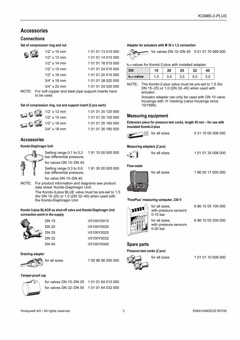
Adapter for actuators with M 30 x 1,5 connection
for valves DN 10–DN 40 0 01 01 70 069 000
kvs-values for Kombi-2-plus with installed adapter:DN 15 20 25 32 40kvs-value 1,5 3,5 3,5 5,5 5,5
NOTE: The Kombi-2-plus valve must be pre-set to 1.5 (forDN 15–25) or 1.0 (DN 32–40) when used withactuator.Actuator adapter can only be used with DN 10 valvehousings with ‘H’ marking (valve housings since10/1999).
Measuring equipmentExtension piece for pressure test cocks, length 45 mm – for use withinsulated Kombi-2-plus
for all sizes 0 21 10 05 008 000
Measuring adapters (2 pcs)
for all sizes 1 01 01 35 008 000
Flow meter
for all sizes 1 86 00 17 000 000
‘FlowPlus’ measuring computer, 230 V
for all sizes,with pressure sensors0-10 bar
6 86 10 05 100 000
for all sizes,with pressure sensors0-20 bar
6 86 10 05 200 000
Spare partsPressure test cocks (2 pcs)
for all sizes 1 01 01 10 008 000
KOMBI-2-PLUS
EN0H-048GE25 R0700 4 Honeywell AG • All rights reserved
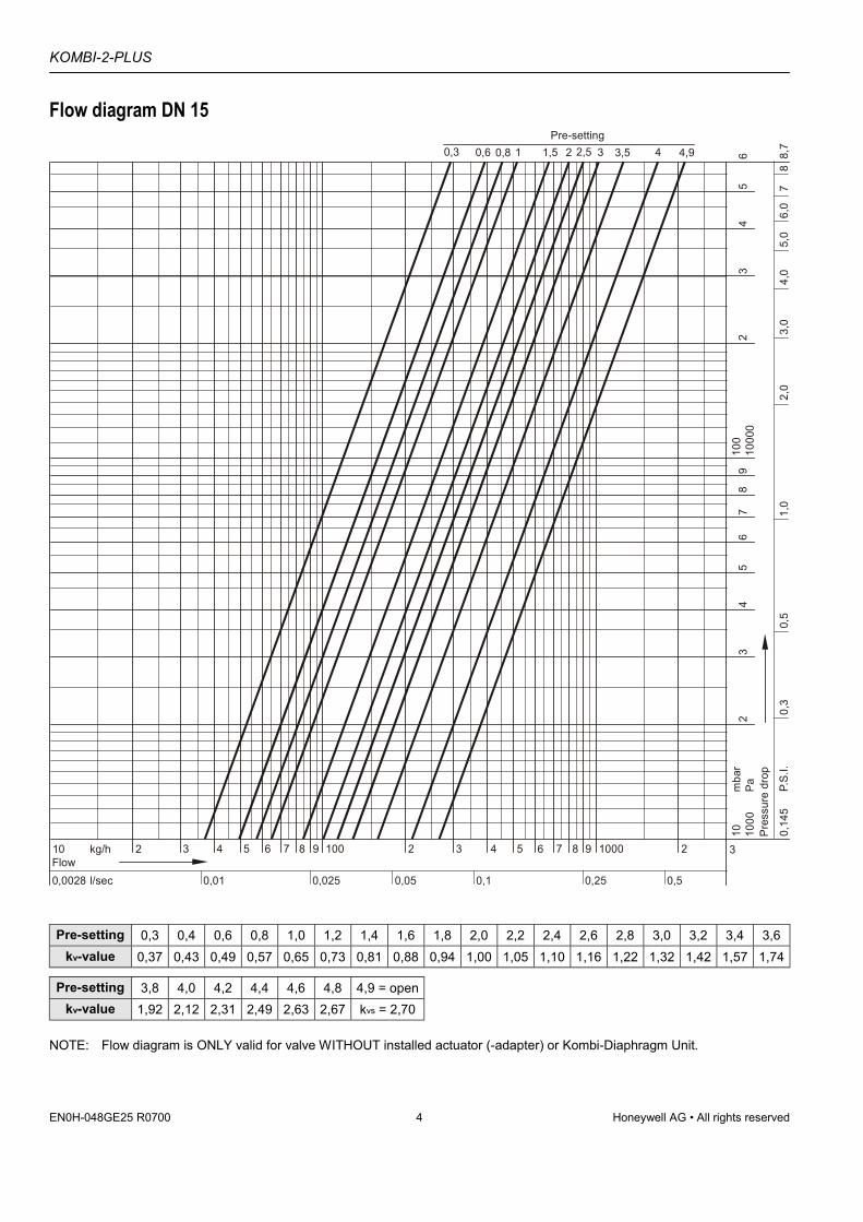
Flow diagram DN 15
10 2 4kg/hFlow
0,025 0,050,0028 0,01 0,5l/sec
3 5 6 7 8 1009 2 4 5 6 7 8 100093 2 3
0,1 0,25
1000
100
23
45
67
89
1000
02
34
56
Pres
sure
dro
p
10Pam
bar
0,14
5P.
S.I.
0,3
0,5
1,0
2,0
3,0
4,0
6,0
88,
77
5,0
1,5 2 2,5 31Pre-setting
0,80,6 3,5 40,3 4,9
Pre-setting 0,3 0,4 0,6 0,8 1,0 1,2 1,4 1,6 1,8 2,0 2,2 2,4 2,6 2,8 3,0 3,2 3,4 3,6kv-value 0,37 0,43 0,49 0,57 0,65 0,73 0,81 0,88 0,94 1,00 1,05 1,10 1,16 1,22 1,32 1,42 1,57 1,74
Pre-setting 3,8 4,0 4,2 4,4 4,6 4,8 4,9 = openkv-value 1,92 2,12 2,31 2,49 2,63 2,67 kvs = 2,70
NOTE: Flow diagram is ONLY valid for valve WITHOUT installed actuator (-adapter) or Kombi-Diaphragm Unit.
KOMBI-2-PLUS
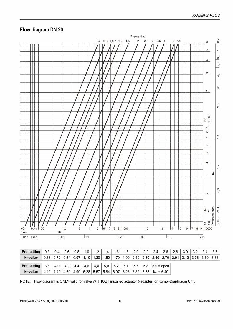
Honeywell AG • All rights reserved 5 EN0H-048GE25 R0700
Flow diagram DN 20
60 100kg/hFlow
0,10,017 0,05 2,5l/sec
2 4 5 6 7 8 100093 2 4 5 6 7 8 1000093
0,25 0,5 1,0
1000
100
23
45
67
89
1000
02
34
56
Pres
sure
dro
p
10Pam
bar
0,14
5P.
S.I.
0,3
0,5
1,0
2,0
3,0
4,0
6,0
88,
77
5,0
1,5 2 2,5 31Pre-setting
0,80,6 3,5 40,3 51,2 5,9
Pre-setting 0,3 0,4 0,6 0,8 1,0 1,2 1,4 1,6 1,8 2,0 2,2 2,4 2,6 2,8 3,0 3,2 3,4 3,6kv-value 0,68 0,72 0,84 0,97 1,10 1,30 1,50 1,70 1,90 2,10 2,30 2,50 2,70 2,91 3,12 3,36 3,60 3,86
Pre-setting 3,8 4,0 4,2 4,4 4,6 4,8 5,0 5,2 5,4 5,6 5,8 5,9 = openkv-value 4,12 4,40 4,69 4,99 5,28 5,57 5,84 6,07 6,26 6,32 6,38 kvs = 6,40
NOTE: Flow diagram is ONLY valid for valve WITHOUT installed actuator (-adapter) or Kombi-Diaphragm Unit.
KOMBI-2-PLUS
EN0H-048GE25 R0700 6 Honeywell AG • All rights reserved
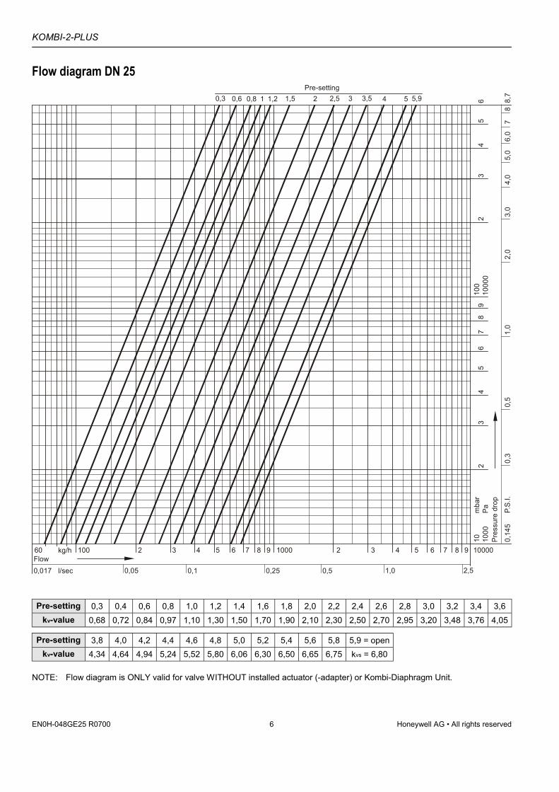
Flow diagram DN 25
60 100kg/hFlow
0,10,017 0,05 2,5l/sec
2 4 5 6 7 8 100093 2 4 5 6 7 8 1000093
0,25 0,5 1,0
1000
100
23
45
67
89
1000
02
34
56
Pres
sure
dro
p
10Pam
bar
0,14
5P.
S.I.
0,3
0,5
1,0
2,0
3,0
4,0
6,0
88,
77
5,0
1,5 2 2,5 31Pre-setting
0,80,6 3,5 40,3 51,2 5,9
Pre-setting 0,3 0,4 0,6 0,8 1,0 1,2 1,4 1,6 1,8 2,0 2,2 2,4 2,6 2,8 3,0 3,2 3,4 3,6kv-value 0,68 0,72 0,84 0,97 1,10 1,30 1,50 1,70 1,90 2,10 2,30 2,50 2,70 2,95 3,20 3,48 3,76 4,05
Pre-setting 3,8 4,0 4,2 4,4 4,6 4,8 5,0 5,2 5,4 5,6 5,8 5,9 = openkv-value 4,34 4,64 4,94 5,24 5,52 5,80 6,06 6,30 6,50 6,65 6,75 kvs = 6,80
NOTE: Flow diagram is ONLY valid for valve WITHOUT installed actuator (-adapter) or Kombi-Diaphragm Unit.
KOMBI-2-PLUS
Honeywell AG • All rights reserved 7 EN0H-048GE25 R0700
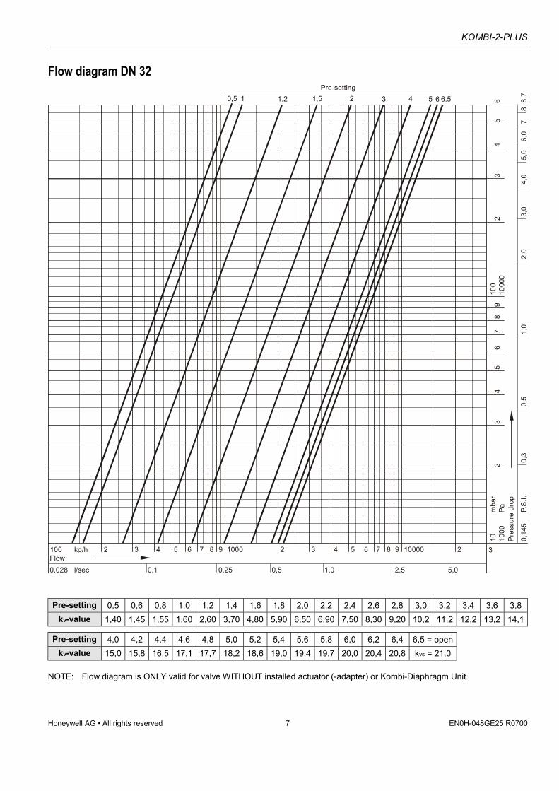
Flow diagram DN 32
100 2 4kg/hFlow
0,25 0,50,028 0,1 5,0l/sec
3 5 6 7 8 10009 2 4 5 6 7 8 1000093 2 3
1,0 2,5
1000
100
23
45
67
89
1000
02
34
56
Pres
sure
dro
p
10Pam
bar
0,14
5P.
S.I.
0,3
0,5
1,0
2,0
3,0
4,0
6,0
88,
77
5,0
1,5 2 3 4Pre-setting
1,21 5 60,5 6,5
Pre-setting 0,5 0,6 0,8 1,0 1,2 1,4 1,6 1,8 2,0 2,2 2,4 2,6 2,8 3,0 3,2 3,4 3,6 3,8kv-value 1,40 1,45 1,55 1,60 2,60 3,70 4,80 5,90 6,50 6,90 7,50 8,30 9,20 10,2 11,2 12,2 13,2 14,1
Pre-setting 4,0 4,2 4,4 4,6 4,8 5,0 5,2 5,4 5,6 5,8 6,0 6,2 6,4 6,5 = openkv-value 15,0 15,8 16,5 17,1 17,7 18,2 18,6 19,0 19,4 19,7 20,0 20,4 20,8 kvs = 21,0
NOTE: Flow diagram is ONLY valid for valve WITHOUT installed actuator (-adapter) or Kombi-Diaphragm Unit.
KOMBI-2-PLUS
EN0H-048GE25 R0700 8 Honeywell AG • All rights reserved
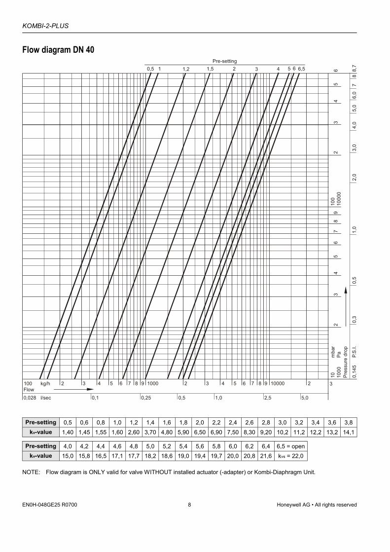
Flow diagram DN 40
100 2 4kg/hFlow
0,25 0,50,028 0,1 5,0l/sec
3 5 6 7 8 10009 2 4 5 6 7 8 1000093 2 3
1,0 2,5
1000
100
23
45
67
89
1000
02
34
56
Pres
sure
dro
p
10Pam
bar
0,14
5P.
S.I.
0,3
0,5
1,0
2,0
3,0
4,0
6,0
88,
77
5,0
1,5 2 3 4Pre-setting
1,21 5 60,5 6,5
Pre-setting 0,5 0,6 0,8 1,0 1,2 1,4 1,6 1,8 2,0 2,2 2,4 2,6 2,8 3,0 3,2 3,4 3,6 3,8kv-value 1,40 1,45 1,55 1,60 2,60 3,70 4,80 5,90 6,50 6,90 7,50 8,30 9,20 10,2 11,2 12,2 13,2 14,1
Pre-setting 4,0 4,2 4,4 4,6 4,8 5,0 5,2 5,4 5,6 5,8 6,0 6,2 6,4 6,5 = openkv-value 15,0 15,8 16,5 17,1 17,7 18,2 18,6 19,0 19,4 19,7 20,0 20,8 21,6 kvs = 22,0
NOTE: Flow diagram is ONLY valid for valve WITHOUT installed actuator (-adapter) or Kombi-Diaphragm Unit.
KOMBI-2-PLUS
Honeywell AG • All rights reserved 9 EN0H-048GE25 R0700
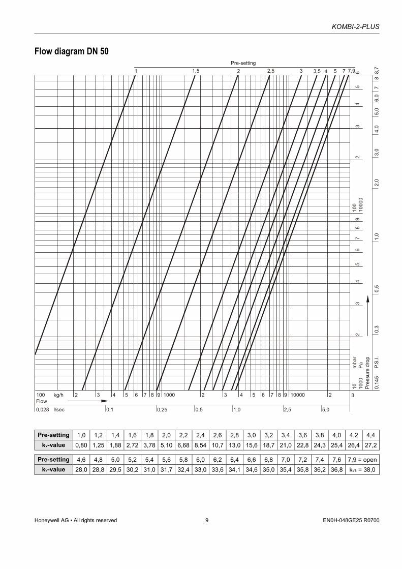
Flow diagram DN 50
100 2 4kg/hFlow
0,25 0,50,028 0,1 5,0l/sec
3 5 6 7 8 10009 2 4 5 6 7 8 1000093 2 3
1,0 2,5
1000
100
23
45
67
89
1000
02
34
56
Pres
sure
dro
p
10Pam
bar
0,14
5P.
S.I.
0,3
0,5
1,0
2,0
3,0
4,0
6,0
88,
77
5,0
2,5 3 3,5 4Pre-setting
21,5 5 71 7,9
Pre-setting 1,0 1,2 1,4 1,6 1,8 2,0 2,2 2,4 2,6 2,8 3,0 3,2 3,4 3,6 3,8 4,0 4,2 4,4kv-value 0,80 1,25 1,88 2,72 3,78 5,10 6,68 8,54 10,7 13,0 15,6 18,7 21,0 22,8 24,3 25,4 26,4 27,2
Pre-setting 4,6 4,8 5,0 5,2 5,4 5,6 5,8 6,0 6,2 6,4 6,6 6,8 7,0 7,2 7,4 7,6 7,9 = openkv-value 28,0 28,8 29,5 30,2 31,0 31,7 32,4 33,0 33,6 34,1 34,6 35,0 35,4 35,8 36,2 36,8 kvs = 38,0
KOMBI-2-PLUS
EN0H-048GE25 R0700 10 Honeywell AG • All rights reserved
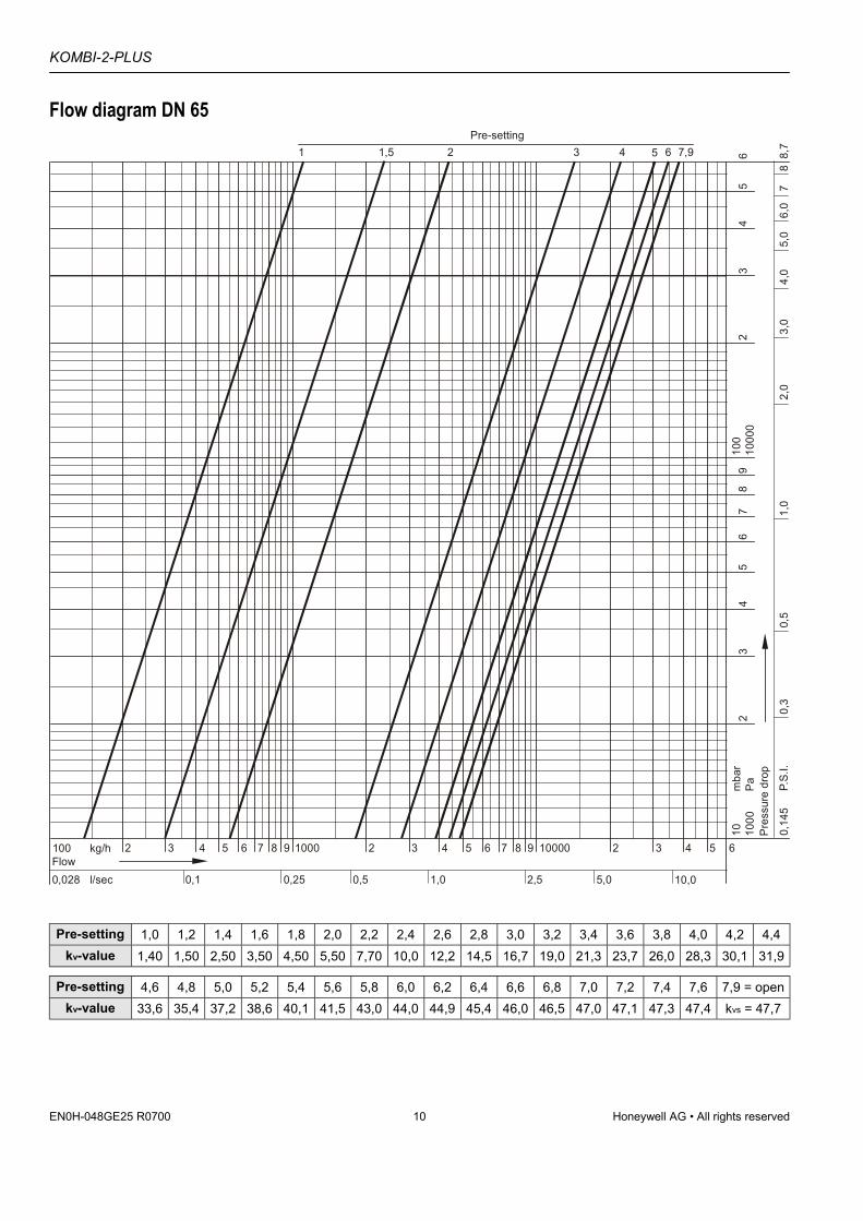
Flow diagram DN 65
100 2 4 5 6 7 8 1000kg/hFlow
9
0,25 0,50,028 0,1 5,0l/sec
3 2 4 5 6 7 8 1000093 2 4 5 63
1,0 2,5 10,0
1000
100
23
45
67
89
1000
02
34
56
Pres
sure
dro
p
10Pam
bar
0,14
5P.
S.I.
0,3
0,5
1,0
2,0
3,0
4,0
6,0
88,
77
5,0
1,5 2 3 41Pre-setting
5 6 7,9
Pre-setting 1,0 1,2 1,4 1,6 1,8 2,0 2,2 2,4 2,6 2,8 3,0 3,2 3,4 3,6 3,8 4,0 4,2 4,4kv-value 1,40 1,50 2,50 3,50 4,50 5,50 7,70 10,0 12,2 14,5 16,7 19,0 21,3 23,7 26,0 28,3 30,1 31,9
Pre-setting 4,6 4,8 5,0 5,2 5,4 5,6 5,8 6,0 6,2 6,4 6,6 6,8 7,0 7,2 7,4 7,6 7,9 = openkv-value 33,6 35,4 37,2 38,6 40,1 41,5 43,0 44,0 44,9 45,4 46,0 46,5 47,0 47,1 47,3 47,4 kvs = 47,7
KOMBI-2-PLUS
Honeywell AG • All rights reserved 11 EN0H-048GE25 R0700
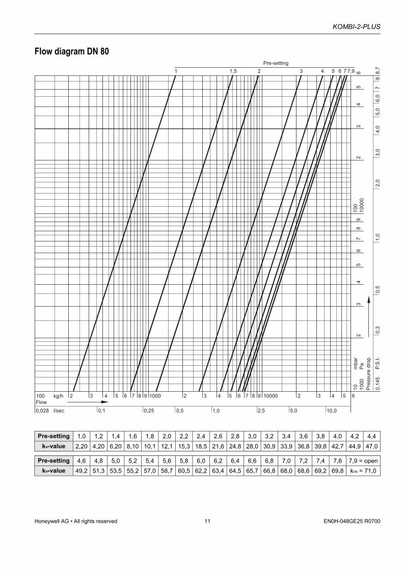
Flow diagram DN 80
100 2 4 5 6 7 8 1000kg/hFlow
9
0,25 0,50,028 0,1 5,0l/sec
3 2 4 5 6 7 8 1000093 2 4 5 63
1,0 2,5 10,0
1000
100
23
45
67
89
1000
02
34
56
Pres
sure
dro
p
10Pam
bar
0,14
5P.
S.I.
0,3
0,5
1,0
2,0
3,0
4,0
6,0
88,
77
5,0
1,5 2 3 41Pre-setting
5 6 7,97
Pre-setting 1,0 1,2 1,4 1,6 1,8 2,0 2,2 2,4 2,6 2,8 3,0 3,2 3,4 3,6 3,8 4,0 4,2 4,4kv-value 2,20 4,20 6,20 8,10 10,1 12,1 15,3 18,5 21,6 24,8 28,0 30,9 33,9 36,8 39,8 42,7 44,9 47,0
Pre-setting 4,6 4,8 5,0 5,2 5,4 5,6 5,8 6,0 6,2 6,4 6,6 6,8 7,0 7,2 7,4 7,6 7,9 = openkv-value 49,2 51,3 53,5 55,2 57,0 58,7 60,5 62,2 63,4 64,5 65,7 66,8 68,0 68,6 69,2 69,8 kvs = 71,0
KOMBI-2-PLUS
Home and Building ControlHoneywell AG Phone: (49) 2932 9880Zu den Ruhrwiesen 3 Fax: (49) 2932 988239D-59755 Arnsberg-Neheim [email protected] http://europe.hbc.honeywell.com
EN0H-048GE25 R0700 12 Subject to change • All rights reserved
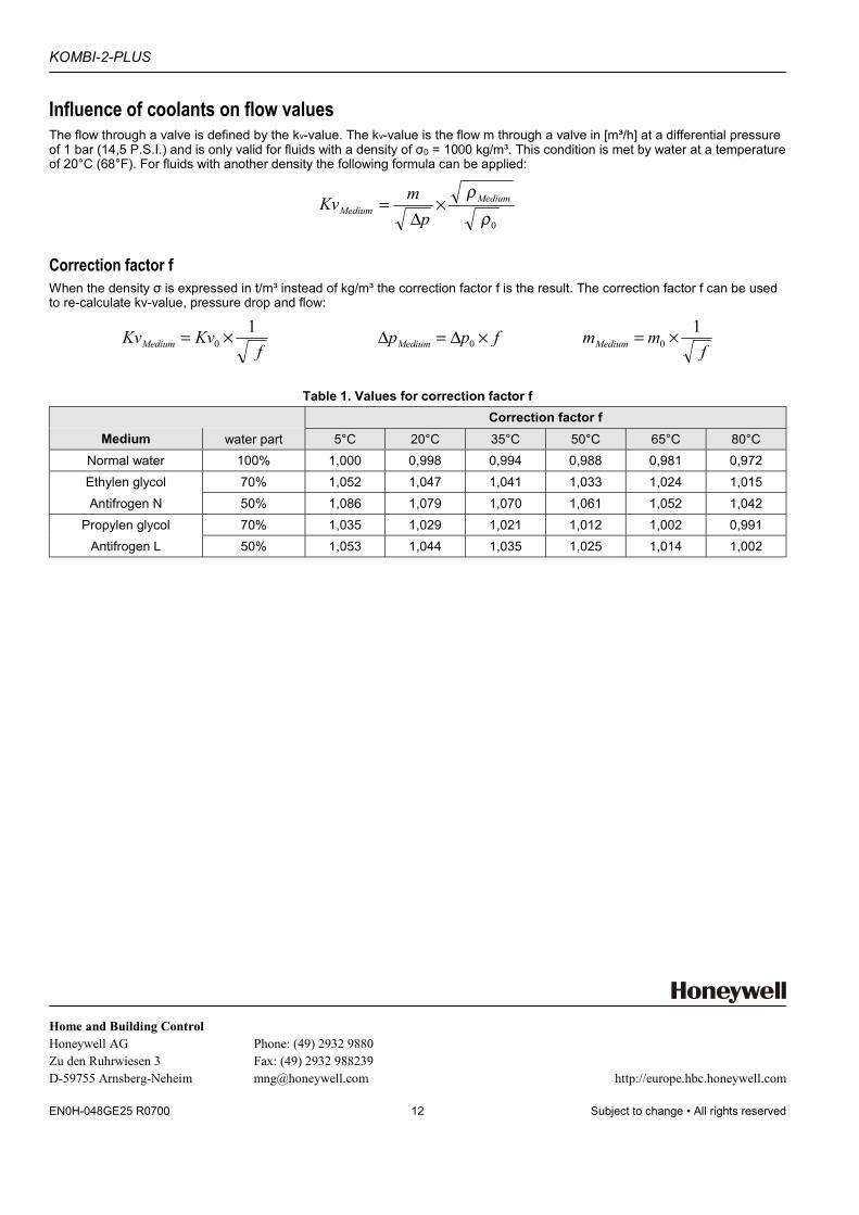
Influence of coolants on flow valuesThe flow through a valve is defined by the kv-value. The kv-value is the flow m through a valve in [m³/h] at a differential pressureof 1 bar (14,5 P.S.I.) and is only valid for fluids with a density of σ0 = 1000 kg/m³. This condition is met by water at a temperatureof 20°C (68°F). For fluids with another density the following formula can be applied:
0ρρMedium
Medium pmKv ×∆
=
Correction factor fWhen the density σ is expressed in t/m³ instead of kg/m³ the correction factor f is the result. The correction factor f can be usedto re-calculate kv-value, pressure drop and flow:
fKvKvMedium
10 ×= fppMedium ×∆=∆ 0 f
mmMedium1
0 ×=
Table 1. Values for correction factor fCorrection factor f
Medium water part 5°C 20°C 35°C 50°C 65°C 80°CNormal water 100% 1,000 0,998 0,994 0,988 0,981 0,972Ethylen glycol 70% 1,052 1,047 1,041 1,033 1,024 1,015Antifrogen N 50% 1,086 1,079 1,070 1,061 1,052 1,042
Propylen glycol 70% 1,035 1,029 1,021 1,012 1,002 0,991Antifrogen L 50% 1,053 1,044 1,035 1,025 1,014 1,002