Embed Size (px)
Citation preview
PD32*282410*
2824
10
pt
Operating instructions 1–30
Mode d’emploi 31–60
Istruzioni d’uso 61–90
Manual de instruções 91–120
Manual deinstrucciones 121–150
en
fr
es
it
Printed: 07.07.2013 | Doc-Nr: PUB / 5070013 / 000 / 00
�
5 2
4 9
6
3 1
7
12
810
10
11
11
11
13
Printed: 07.07.2013 | Doc-Nr: PUB / 5070013 / 000 / 00
PDAW 80-1
�
PDA 50
PDA 60
PDA 61
PDA 62
PDA 70
PDAW 80 / 81-3
PDAW 81-1
PDAW 80 / 81-2
PDAW 80 / 81-1
PDA 81
PDA 80
PUA 60
Printed: 07.07.2013 | Doc-Nr: PUB / 5070013 / 000 / 00
1
PD 32 laser range meter Contents
It is essential that the operatinginstructions are read before the rangemeter is used the first time.
Always keep these operating instruc-tions together with the tool.
Ensure that the operating instructionsare with the range meter when it isgiven to other persons.
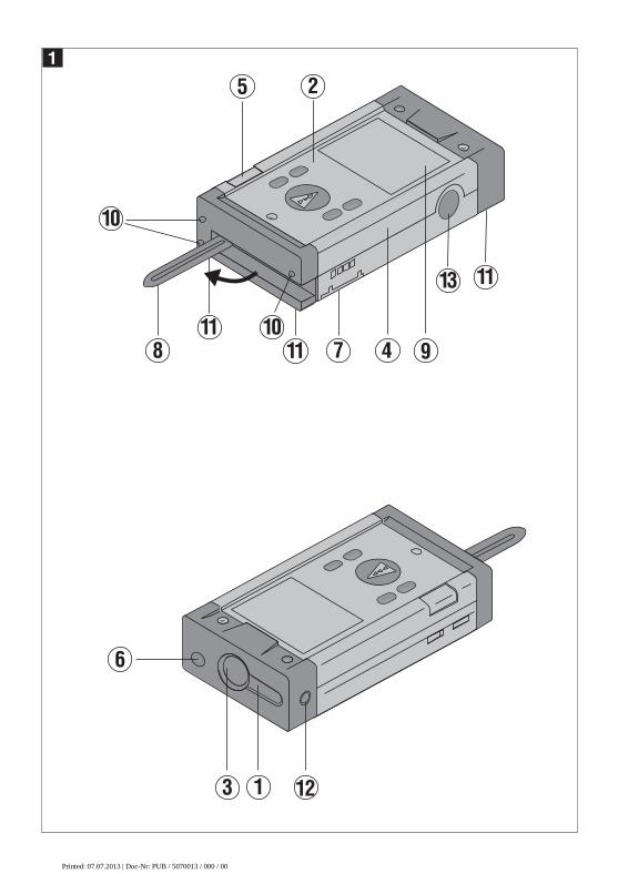
Component parts �
� Laser exit aperture� Control panel� Receiving lens� Plastic casing� Horizontal bubble � Vertical bubble� Battery compartment Folding spike Graphic display of operating status� Metal contact points for precise meas-
urement (3x rear)� Metal supports for precise measure-
ment (3x underneath) Optical sight� Side measuring key
Contents
1. General information. . . . . . . . . . 31.1. Safety notices and their meaning 31.2. Pictograms . . . . . . . . . . . . . . . . . 31.3. Location of identification data on
the range meter . . . . . . . . . . . . . 3
2. Description . . . . . . . . . . . . . . . . . 42.1. Intended use . . . . . . . . . . . . . . . . 42.2. Items supplied . . . . . . . . . . . . . . 42.3. Measuring principle . . . . . . . . . . 42.4. Range meter functions . . . . . . . . 42.4.1. General range meter functions . . 42.4.2. PD 32 side measurement key . . . 42.4.3. PD 32 optical sight . . . . . . . . . . . 4
3. Tools and accessories . . . . . . . . 53.1. PDA 50 target plate. . . . . . . . . . . 53.2. PDA 80 / 81charging kits . . . . . . 53.3. PDAW 80-1 mains adaptor . . . . . 63.4. PDAW 80 / 81-2 car battery plug 63.5. PDAW 80 / 81-1 charging adaptor63.6. PDAW 80 / 81-3 battery pack . . . 63.7. PDAW 81-1 mains adaptor . . . . . 63.8. PUA 60 laser visibility glasses . . 63.9. Belt clip PDA 62 . . . . . . . . . . . . . 63.10. Measuring extension PDA 70 . . . 6
4. Technical data . . . . . . . . . . . . . . 7
5. Safety information . . . . . . . . . . . 85.1. Basic safety information . . . . . . . 85.2. Misuse . . . . . . . . . . . . . . . . . . . . 85.3. General safety precautions . . . . . 85.4. Proper organization of workplace 95.4.1. Electromagnetic compatibility . . . 95.4.2. Laser classification . . . . . . . . . . . 95.4.3. Transport . . . . . . . . . . . . . . . . . . 9
Printed: 07.07.2013 | Doc-Nr: PUB / 5070013 / 000 / 00
2
Contents
6. Getting started . . . . . . . . . . . . . 106.1. Inserting alkaline / rechargeable
batteries . . . . . . . . . . . . . . . . . . 106.2. Battery charging . . . . . . . . . . . . 106.2.1. Standard charging of batteries . 106.2.2. Fast battery charging . . . . . . . . 116.3. Switching the range meter On
and Off . . . . . . . . . . . . . . . . . . . 116.3.1. Initial distances measurement . 116.4. Settings . . . . . . . . . . . . . . . . . . 126.4.1. Activating the setting menu . . . 126.4.2. Menu / Beep . . . . . . . . . . . . . . . 126.4.3. Menu / Units . . . . . . . . . . . . . . . 126.4.4. Terminating the menu. . . . . . . . 12
7. Operation . . . . . . . . . . . . . . . . . 127.1. General controls . . . . . . . . . . . . 127.1.1. Control panel . . . . . . . . . . . . . . 127.1.2. On and switch keys. . . . . . . . . . 127.1.3. Measure keys . . . . . . . . . . . . . . 137.1.4. Function keys . . . . . . . . . . . . . . 137.2. Display . . . . . . . . . . . . . . . . . . . 137.2.1. Symbols displayed . . . . . . . . . . 147.2.2. Display illumination . . . . . . . . . 157.3. Optical sight . . . . . . . . . . . . . . . 157.4. Measuring distances. . . . . . . . . 157.4.1. Measuring references . . . . . . . 157.4.2. Measuring distances step by step 167.4.3. Measurement mode . . . . . . . . . 167.4.4. Measuring from corners . . . . . . 177.4.5. Measuring with the aid of
target objects . . . . . . . . . . . . . . 187.4.6. Measuring in bright surroundings187.4.7. Taking measurements to
rough surfaces . . . . . . . . . . . . . 187.4.8. Taking measurements to
round or inclined surfaces . . . . 187.4.9. Taking measurements to
wet or shiny surfaces . . . . . . . . 187.4.10. Taking measurements to
transparent surfaces . . . . . . . . . 197.4.11. Measuring ranges . . . . . . . . . . . 19
8. Applications . . . . . . . . . . . . . . . 198.1. Measurement data memory . . . 198.1.1. Saving measurements . . . . . . . 198.1.2. Historical data memory. . . . . . . 208.2. Area measurement . . . . . . . . . . 208.3. Volume measurement . . . . . . . . 208.4. Adding distances . . . . . . . . . . . 218.5. Subtracting distances . . . . . . . . 228.6. Indirect measurement. . . . . . . . 228.6.1. Measuring criteria . . . . . . . . . . . 238.6.2. Selecting indirect measurement
options . . . . . . . . . . . . . . . . . . . 238.6.3. Indirect measurement
(combined version). . . . . . . . . . 238.6.4. Indirect measurement (simple
version). . . . . . . . . . . . . . . . . . . 248.7. Max / Min measurement . . . . . . 248.7.1. Max measurement . . . . . . . . . . 248.7.2. Min measurement. . . . . . . . . . . 258.7.3. Combined measurement. . . . . . 258.8. Setting out . . . . . . . . . . . . . . . . 26
9. Calibration and adjustment . . . 269.1. Calibration. . . . . . . . . . . . . . . . . 269.2. Adjustment . . . . . . . . . . . . . . . . 279.3. Hilti calibration service . . . . . . . 27
10. Care and maintenance. . . . . . . 2710.1. Cleaning and drying . . . . . . . . . 2710.2. Storage . . . . . . . . . . . . . . . . . . . 2710.3. Transportation. . . . . . . . . . . . . . 27
11. Disposal . . . . . . . . . . . . . . . . . . 28
12. Manufacturer's warranty – tools . . . . . . . . . . . . . . . . . . . . . 28
13. FCC statement (applicable in USA) . . . . . . . . . . . . . . . . . . . 29
14. EC declaration of conformity . . 30
Printed: 07.07.2013 | Doc-Nr: PUB / 5070013 / 000 / 00
3
1. General information
1. General information
1.1 Safety notices and their meaning
- CAUTION -This word indicates a possibly hazardoussituation which could result in slight bodilyinjuries or damage to property.
- NOTE -This word indicates information to help theuser employ the product efficiently, andother useful notes.
1.2 Pictograms
Warning signs
Symbols
� These numbers refer to the correspon-ding illustrations. The illustrations can befound on the fold-out cover pages. Keepthese pages open when studying the oper-ating instructions. In these operatinginstructions, the PD 32 laser range meter isreferred to as "the range meter".
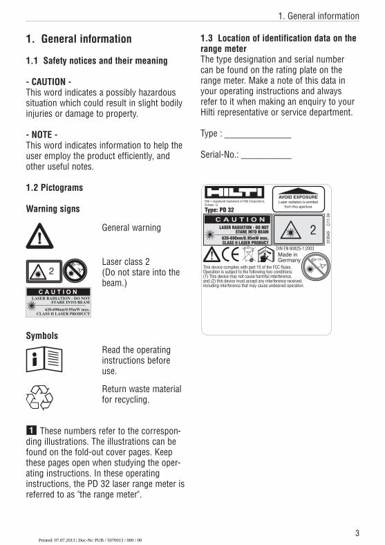
1.3 Location of identification data on therange meterThe type designation and serial numbercan be found on the rating plate on therange meter. Make a note of this data inyour operating instructions and alwaysrefer to it when making an enquiry to yourHilti representative or service department.
Type :
Serial-No.: ___________
General warning
Laser class 2(Do not stare into thebeam.)
Read the operatinginstructions beforeuse.
Return waste materialfor recycling.
CLASS II LASER PRODUCT620-690nm/0.95mW max.
STARE INTO BEAMLASER RADIATION - DO NOT 2
1/4 s
3195
49
C/1
1.04
This device complies with part 15 of the FCC Rules. Operation is subject to the following two conditions:(1) This device may not cause harmful interference, and (2) this device must accept any interference received,including interference that may cause undesired operation.
AVOID EXPOSURELaser radiation is emitted
from this aperture
Hilti = registered trademark of Hilti Corporation, Schaan, LI
Type: PD 32
Made in Germany
DIN EN 60825-1:2003
Printed: 07.07.2013 | Doc-Nr: PUB / 5070013 / 000 / 00
4
2. Description
2. Description
The distance is determined along an emitted laser beam up to the surface wherethe laser beam is reflected. The red laserspot clearly identifies the target from whichthe measurement is taken.
The measuring range depends on thereflectivity and the surface structure of thetarget surface.
2.1 Intended useThe range meter is designed for the:– Measurement of distances– Calculation of areas, volumes and distances– Addition and subtraction of distances– Operation and storage in the specified
temperatures
2.2 Items supplied1 PD 32 laser range meter1 PDA 50 target plate1 PDA 60 hand strap 2 Type AA batteries1 soft pouch1 Operating instructions1 Producer Certificate
2.3 Measuring principleThe range meter emits a visible laser beamwith measuring waves, which are reflectedreturning with a phase shift. The phaseshift is used to determine the distance.
This measuring principle permits highlyaccurate and reliable distance measurements to objects without special reflectors.
2.4 Range meter functions
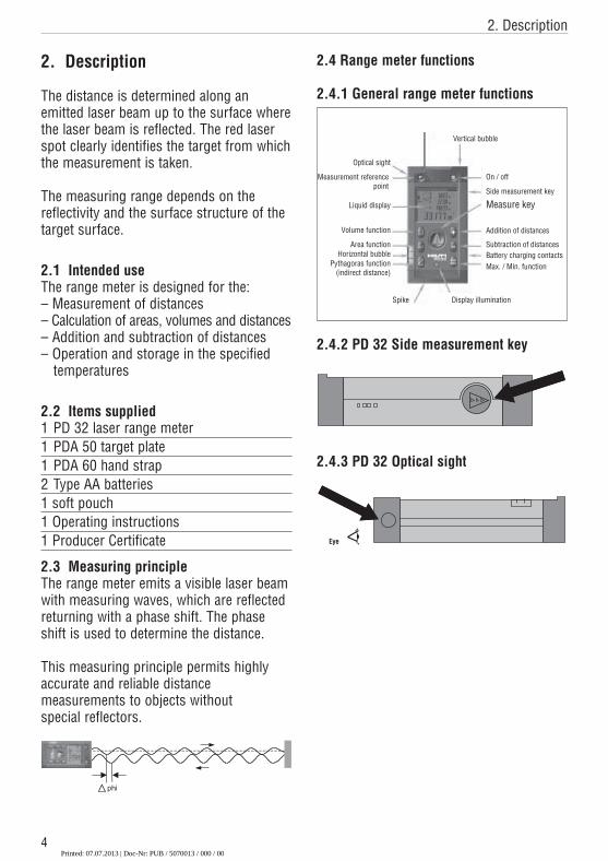
2.4.1 General range meter functions
2.4.2 PD 32 Side measurement key
2.4.3 PD 32 Optical sight
Eye
phi
Optical sight
Measurement reference point
On / off
Vertical bubble
Side measurement key
Measure key
Addition of distances
Subtraction of distancesBattery charging contactsMax. / Min. function
Liquid display
Volume function
Area functionHorizontal bubble
Pythagoras function(indirect distance)
Spike Display illumination
Printed: 07.07.2013 | Doc-Nr: PUB / 5070013 / 000 / 00
5
3. Tools and accessories
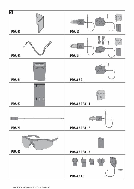
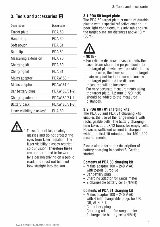
3. Tools and accessories �
Description Designation
Target plate PDA 50
Hand strap PDA 60
Soft pouch PDA 61
Belt clip PDA 62
Measuring extension PDA 70
Charging kit PDA 80
Charging kit PDA 81
Mains adaptor PDAW 80-1
Mains adaptor PDAW 81-1
Car battery plug PDAW 80/81-2
Charging adaptor PDAW 80/81-1
Battery pack PDAW 80/81-3
Laser visibility glasses* PUA 60
* These are not laser safety glasses and do not protect theeyes from laser radiation. Thelaser visibility glasses restrictcolour vision. Therefore theseare not permitted to be worn by a person driving on a publicroad, and must not be used look straight into the sun.
3.1 PDA 50 target plateThe PDA 50 target plate is made of durableplastic with a special reflective coating. Inpoor light conditions, it is advisable to usethe target plate for distances above 10 m(30 ft).
- NOTE -– For reliable distance measurements the
laser beam should be perpendicular to the target plate whenever possible. If thisnot the case, the laser spot on the target plate may not be in the same plane as the target point and the distance measured will be incorrect.
– For very accurate measurements using the target plate, 1.2 mm (1/20 inch) should be added to the measured distances.
3.2 PDA 80 / 81 charging kitsThe PDA 80 and PDA 81 charging kits enables the use of the range meters withrechargeable cells. The battery chargingtime takes approx.12 hours for empty cells.However, sufficient current is charged within the first 15 minutes – for 150 - 200 measurements.
Please also refer to the description ofbattery charging in section 6. Getting started.
Contents of PDA 80 charging kit– Mains adaptor 100 – 240 V AC
with 2-pole Europlug– Car battery plug– Charging adaptor for range meter– 2 chargeable battery cells (NiMH)
Contents of PDA 81 charging kit– Mains adaptor 100 – 240 V AC
with 4 interchangeable plugs for US, GB, AUS, EU.
– Car battery plug – Charging adaptor for range meter– 2 chargeable battery cells(NiMH)
Printed: 07.07.2013 | Doc-Nr: PUB / 5070013 / 000 / 00
6
3. Tools and accessories
3.3 PDAW 80-1 mains adaptorThe mains adaptor is an integral part of thecharging kit. It is equipped with a two pinplug. The mains adaptor transforms thepower supply from alternating current todirect current which is used to charge thebatteries. The mains adaptor automaticallyadjusts itself to suit an AC voltage between100 - 240 V and 50 - 60 Hz. The mainsadaptor has been specially designed tosupply current to the charging adaptor.
- NOTE -Battery chargers or mains adaptors withother voltage outputs, such as those formobile phones, may not be used. Use ofother battery chargers or mains adaptorsmay damage the range meter.
3.4 PDAW 80/81-2 car battery plugThe car battery plug is an integral part ofthe PDA 80/81 charging kit. It can be inserted into a vehicle cigarette lighter or into sockets of the same design. This adaptor has a special design and transforms the 12 - 24 V direct current ofa vehicle battery into a voltage suitable forthe charging adaptor.A light-emitting diode (LED) is incorporated in the adaptor to indicate correct connection for charging. Anadditionalfuse in the adapters front sectionprovides protection against voltage peaks.
- NOTE -As the car battery plug has been especiallydesigned to charge the NiMH batteries of the PD 32, it may not be replaced by othertypes of car battery plugs.
3.5 PDAW 80/81-1 charging adaptorThe respective mains adaptor supplies current to the charging adaptor. Prior tocharging the battery, the side flange connections should be carefully checked.
3.6 PDAW 80/81-3 battery packThe battery pack consists of two rechargeable, 1.2-V NiMH cells with acapacity of approx.1800 mAh. The batterypack remains in the battery compartmentwhile being charged.
- NOTE -– A "memory effect" is virtually
non-existent with this type of batteries and the charging process used. The charging process can be interrupted at any time without damaging the battery cells.
– Other brands of rechargeable batteriescan be used. It must be ensured, however, that, as far as possible, batteries have a similar capacity of approx. 1800 mAh.
3.7 PDAW 81-1 mains adaptorThis mains adaptor PDAW 81-1 is virtuallyidentical to the PDAW 80-1 mains adaptor.The only difference is the type of mainsplugs which are interchangeable plugs.
3.8 PUA 60 laser visibility glassesThe laser visibility glasses clearly improvethe visibility of the laser beam (spot)
3.9 Belt clip PDA 62The belt clip is made from durable plasticsand is quickly and easily fixed to the beltusing the snapper. For carrying the rangemeter snaps into position and easilydetaches when being needed.
3.10. Measuring extension PDA 70The measuring extension is made from alu-minium and durable plastic handle.With the help of the belt clip the rangemeter attaches to the measuring extension.The rear reference extends by 1.270 m / 50 inches. Please also refer to chapter 7.Operation for more explanations how tochange the reference setting to use themeasuring extension.
Printed: 07.07.2013 | Doc-Nr: PUB / 5070013 / 000 / 00
7
4. Technical data
4. Technical data
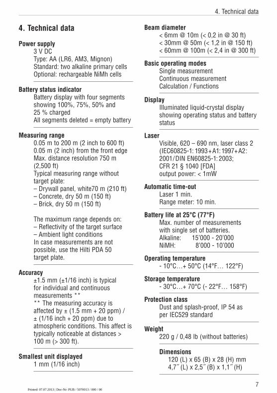
Power supply3 V DCType: AA (LR6, AM3, Mignon)Standard: two alkaline primary cellsOptional: rechargeable NiMh cells
Battery status indicatorBattery display with four segmentsshowing 100%, 75%, 50% and 25 % chargedAll segments deleted = empty battery
Measuring range0.05 m to 200 m (2 inch to 600 ft)0.05 m (2 inch) from the front edgeMax. distance resolution 750 m(2,500 ft)Typical measuring range without target plate:– Drywall panel, white70 m (210 ft)– Concrete, dry 50 m (150 ft)– Brick, dry 50 m (150 ft)
The maximum range depends on:– Reflectivity of the target surface– Ambient light conditionsIn case measurements are not possible, use the Hilti PDA 50 target plate.
Accuracy±1.5 mm (±1/16 inch) is typical for individual and continuous measurements **** The measuring accuracy is affected by ± (1.5 mm + 20 ppm) / ± (1/16 inch + 20 ppm) due toatmospheric conditions. This affect is typically noticeable at distances >100 m (> 300 ft).
Smallest unit displayed1 mm (1/16 inch)
Beam diameter< 6mm @ 10m (< 0,2 in @ 30 ft)< 30mm @ 50m (< 1,2 in @ 150 ft)< 60mm @ 100m (< 2,4 in @ 300 ft)
Basic operating modesSingle measurementContinuous measurementCalculation / Functions
DisplayIlluminated liquid-crystal display showing operating status and batterystatus
LaserVisible, 620 – 690 nm, laser class 2(IEC60825-1: 1993+A1:1997+A2:2001/DIN EN60825-1: 2003;CFR 21 § 1040 [FDA] output power: < 1mW
Automatic time-outLaser 1 min.Range meter: 10 min.
Battery life at 25°C (77°F)Max. number of measurements with single set of batteries.Alkaline: 15’000 - 20’000NiMH: 8’000 - 10’000
Operating temperature- 10°C…+ 50°C (14°F… 122°F)
Storage temperature- 30°C…+ 70°C (- 22°F… 158°F)
Protection classDust and splash-proof, IP 54 as per IEC529 standard
Weight220 g / 0,48 lb (without batteries)
Dimensions120 (L) x 65 (B) x 28 (H) mm4,7˝ (L) x 2,5˝ (B) x 1,1˝ (H)
Printed: 07.07.2013 | Doc-Nr: PUB / 5070013 / 000 / 00
8
5. Safety information
5. Safety information
5.1 Basic safety informationIn addition to the safety precautions listedin the individual sections of these operatinginstructions, the following points must bestrictly observed at all times.
5.2 Misuse
The range meter and its accessories can be a source of hazard if they are not usedproperly or not used for the intended purpose by untrained people.– Do not use the range meter without
suitable prior instruction.– Do not render any safety devices
ineffective and do not remove information and warning notices.
– Have the range meter repaired only at a Hilti service center. Unauthorized opening of the range meter may cause the emission of laser radiation in excess of class 2.
– No changes or manipulations to the range meter are allowed.
– Use only original Hilti accessories and auxiliary tools in order avoid the risk of injury.
– Do not use the range meter in atmospheres where there is a risk of explosion.
– Use only a clean, soft cloth for cleaning.If necessary, moisten the cloth slightly with pure alcohol.
– Keep the range meter out of the reach of children.
– Measurements taken to plastic foam materials, such as polystyrene foam, or to snow or other strongly reflecting surfaces, may be inaccurate.
– Taking measurements to surfaces withlow reflectivity surrounded by areas withhigh reflectivity may lead to measurement errors.
– Measurements taken through panes ofglass or other objects may be inaccurate.
– Rapid changes of the measuring conditions, e.g. persons walking throughthe laser beam, may lead to measurement errors.
– Do not direct the range meter towardsthe sun or other sources of bright light.
– Do not use the range meter as a levellingtool.
– If you do not check the range meter before taking important measurements and after it has been dropped or subjected to other mechanical stressing.
– No checking of the setting of the measuring reference before measuring.
5.3 General safety precautionsCheck the range meter for possible damagebefore use. If the range meter is found tobe damaged, have it repaired at a Hilti service centre. The accuracy of the rangemeter must be checked after it has beendropped or subjected to other mechanicalstressing.– When the range meter is brought into a
warm environment from very cold conditions, or vice versa, allow it tobecome acclimatised before use.
– Although the range meter is designed forthe tough conditions of jobsite use, itshould be treated with care, as otheroptical instruments (binoculars, spectacles, cameras, etc.)
– Although the range meter is protected toprevent entry of dampness, it should bewiped dry each time before being putaway in its transport container.
– As a precaution, check the settings youhave made before using the range meter.
Printed: 07.07.2013 | Doc-Nr: PUB / 5070013 / 000 / 00
9
5. Safety information
– When using the circular bubble level(bull's eye) for alignment, only look atthe range meter from the side.
5.4 Proper organization of workplace
– Secure the area in which you are measuring. When setting up the rangemeter, take care to avoid directing thebeam towards yourself or other people.
– Avoid unfavourable body position whenworking on ladders or scaffolding. Makesure you have a stable stance and avoiddanger of overbalancing at all times.
– Measurements taken through panes ofglass or other objects may be inaccurate.
– Use the range meter only while observingthe specified operating conditions, i.e.not directed towards a mirror, brightchromium steel, polished stone, etc.
– Observe the accident prevention regula-tions in force in the country you areworking.
5.4.1 Electromagnetic compatibilityAlthough the range meter complies withthe strict requirements of the relevant guidelines, Hilti cannot entirely rule out the following possibilities:– The range meter might cause
interference to other equipment, e.g. aircraft navigational equipment.
– The range meter might be subject tointerference caused by powerful radia-tion, which can then lead to incorrectoperation. Check the readings for plausibility when measuring in these conditions or if you are unsure of theresults.
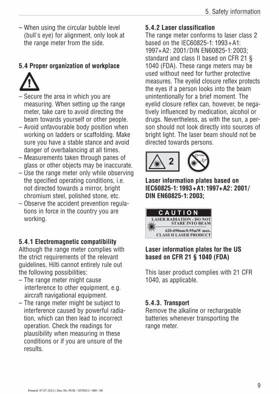
5.4.2 Laser classificationThe range meter conforms to laser class 2based on the IEC60825-1: 1993+A1:1997+A2: 2001/DIN EN60825-1: 2003;standard and class II based on CFR 21 §1040 (FDA). These range meters may beused without need for further protectivemeasures. The eyelid closure reflex pro tectsthe eyes if a person looks into the beamunintentionally for a brief moment. Theeyelid closure reflex can, however, be nega-tively influenced by medication, alcohol ordrugs. Nevertheless, as with the sun, a per-son should not look directly into sources ofbright light. The laser beam should not bedirected towards persons.
Laser information plates based on IEC60825-1: 1993+A1:1997+A2: 2001/DIN EN60825-1: 2003;
Laser information plates for the US based on CFR 21 § 1040 (FDA)
This laser product complies with 21 CFR1040, as applicable.
5.4.3. TransportRemove the alkaline or rechargeable batteries whenever transporting the range meter.
Printed: 07.07.2013 | Doc-Nr: PUB / 5070013 / 000 / 00
10
6. Getting started
6. Getting started
6.1 Inserting alkaline / rechargeable batteries
- CAUTION -– Observe the polarity of the batteries.
(refer to signs inside the battery compartment.)
– Make sure the battery compartment isproperly locked.
1.Lightly press the lid of the battery compartment.
2.Slide the lid out and off.3.Replace the batteries.
- NOTE -For alkaline batteries– Always replace a complete set of
batteries.– Do not mix used and new batteries.– Do not mix batteries of different makes
or types.– Use only undamaged batteries of an
approved type.
For rechargeable batteries– Always use rechargeable batteries of the
same make and same type.
– Always use rechargeable batteries of the same age and charged to the same level.
– New rechargeable batteries are mostly empty and have to be charged prior to first use.
– Use only NiMH batteries with 1.2 V and 1500 – 2000 mAh capacity.
6.2 Battery charging
6.2.1 Standard charging of batteriesThe charging process ensures that thethere will be no "memory effect". In view of this, charging can begin at any timeregardless of the level to which the batteryis already charged.
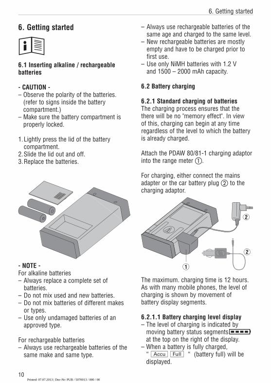
Attach the PDAW 80/81-1 charging adaptorinto the range meter �.
For charging, either connect the mainsadapter or the car battery plug � to the charging adaptor.
The maximum. charging time is 12 hours.As with many mobile phones, the level ofcharging is shown by movement of battery display segments.
6.2.1.1 Battery charging level display– The level of charging is indicated by
moving battery status segmentsat the top on the right of the display.
– When a battery is fully charged,“ “ (battery full) will bedisplayed.
Accu Full
1
2
2
Printed: 07.07.2013 | Doc-Nr: PUB / 5070013 / 000 / 00
11
6. Getting started
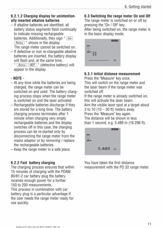
6.2.1.2 Charging display for unintention-ally inserted alkaline batteries – If alkaline batteries are identified, all
battery status segments flash continuallyto indicate missing rechargeable batteries. Additionally, they sign “
“ shows in the display.The range meter cannot be switched on.
– If defective or non re-chargeable alkalinebatteries are inserted, the battery displaywill flash and, at the same time, “ “ (defective battery) willappear in the display.
- NOTE -– At any time while the batteries are being
charged, the range meter can beswitched on and used. The battery charg-ing process stops when the range meteris switched on and the laser activated.
– Rechargeable batteries discharge if theyare stored for a long time. The batterycharging process terminates after 1minute when charging very emptyrechargeable batteries and the displayswitches off in this case, the chargingprocess can be re-started only by disconnecting the range meter from themains adaptor or by removing / replacethe rechargeable batteries.
– Keep the range meter in a safe place.
6.2.2 Fast battery chargingThe charging process ensures that within15 minutes of charging with the PDAW 80/81-2 car battery plug the battery receives enough power for a further 150 to 200 measurements.This process in combination with car battery plug is a particular advantage if the user needs the range meter ready foruse quickly.
noAccu
dEFAccu
6.3 Switching the range meter On and OffThe range meter is switched on or off bypressing the "On / Off" key.After being switched on, the range meter isin the basic display mode.
6.3.1 Initial distance measurementPress the "Measure" key once.This will switch on the range meter and the laser beam if the range meter was switched off.If the range meter is already switched on,this will activate the laser beam.Aim the visible laser spot at a target about3 to 10 (10 – 30 ft) meters away.Press the "Measure" key again.The distance will be shown in less than 1 second, e.g. 5.489 m (16.296 ft).
You have taken the first distance measurement with the PD 32 range meter.
Printed: 07.07.2013 | Doc-Nr: PUB / 5070013 / 000 / 00
12
6. Getting started / 7. Operation
6.4 Settings
6.4.1 Activating the setting menuThe menu is activated by pressing the "On / Off" key pressed for about 2 secondswhile the range meter is switched off.
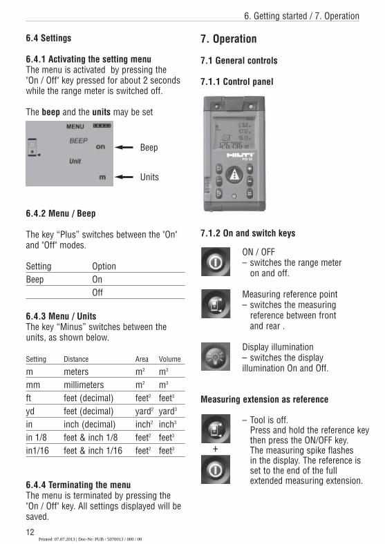
The beep and the units may be set
6.4.2 Menu / Beep
The key “Plus” switches between the "On"and "Off" modes.
Setting OptionBeep On
Off
6.4.3 Menu / UnitsThe key “Minus” switches between theunits, as shown below.
Setting Distance Area Volume
m meters m2 m3
mm millimeters m2 m3
ft feet (decimal) feet2 feet3
yd feet (decimal) yard2 yard3
in inch (decimal) inch2 inch3
in 1/8 feet & inch 1/8 feet2 feet3
in1/16 feet & inch 1/16 feet2 feet3
6.4.4 Terminating the menuThe menu is terminated by pressing the"On / Off" key. All settings displayed will besaved.
Beep
Units
7. Operation
7.1 General controls
7.1.1 Control panel
7.1.2 On and switch keys
ON / OFF– switches the range meter
on and off.
Measuring reference point– switches the measuring
reference between front and rear .
Display illumination– switches the display illumination On and Off.
Measuring extension as reference
– Tool is off.Press and hold the reference keythen press the ON/OFF key.
+ The measuring spike flashes in the display. The reference isset to the end of the full extended measuring extension.
Printed: 07.07.2013 | Doc-Nr: PUB / 5070013 / 000 / 00
13
7. Operation
7.1.3 Measure keys
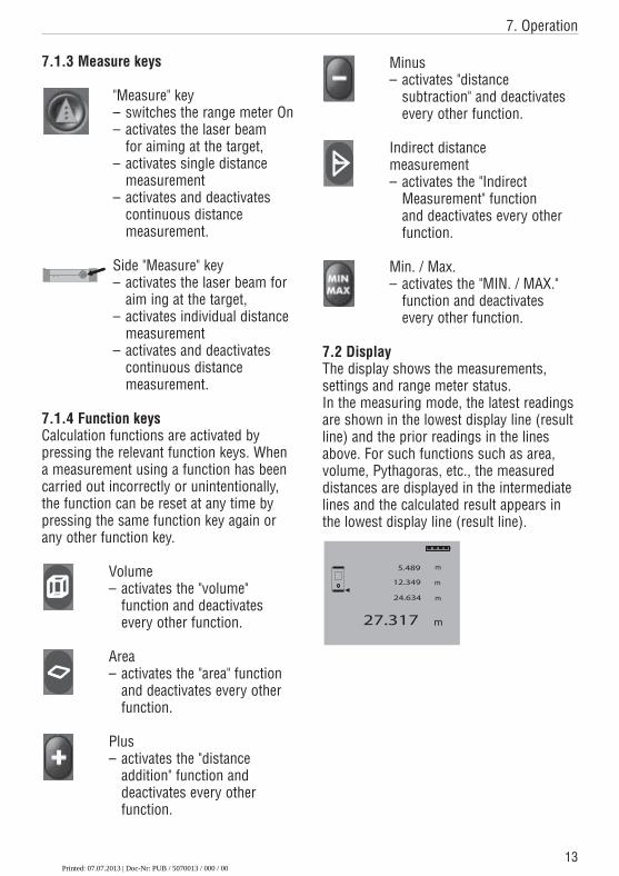
"Measure" key– switches the range meter On– activates the laser beam
for aiming at the target,– activates single distance
measurement – activates and deactivates
continuous distance measurement.
Side "Measure" key– activates the laser beam for
aim ing at the target,– activates individual distance
measurement – activates and deactivates
continuous distance measurement.
7.1.4 Function keysCalculation functions are activated by pressing the relevant function keys. Whena measurement using a function has been carried out incorrectly or unintentionally,the function can be reset at any time bypressing the same function key again orany other function key.
Volume– activates the "volume"
function and deactivates every other function.
Area– activates the "area" function
and deactivates every other function.
Plus– activates the "distance
addition" function and deactivates every other function.
Minus– activates "distance
subtraction" and deactivates every other function.
Indirect distance measurement– activates the "Indirect
Measurement" function and deactivates every other function.
Min. / Max.– activates the "MIN. / MAX."
function and deactivates every other function.
7.2 DisplayThe display shows the measurements, settings and range meter status.In the measuring mode, the latest readingsare shown in the lowest display line (resultline) and the prior readings in the linesabove. For such functions such as area,volume, Pythagoras, etc., the measureddistances are displayed in the intermediatelines and the calculated result appears inthe lowest display line (result line).
Printed: 07.07.2013 | Doc-Nr: PUB / 5070013 / 000 / 00
14
7. Operation
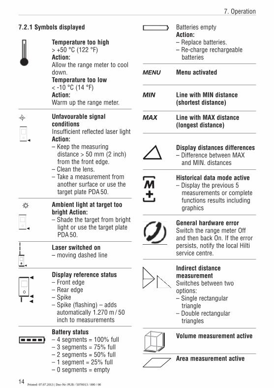
7.2.1 Symbols displayed
Temperature too high> +50 °C (122 °F)Action:Allow the range meter to cooldown.Temperature too low< -10 °C (14 °F)Action:Warm up the range meter.
Unfavourable signal conditionsInsufficient reflected laser lightAction:– Keep the measuring
distance > 50 mm (2 inch)from the front edge.
– Clean the lens.– Take a measurement from
another surface or use thetarget plate PDA 50.
Ambient light at target toobright Action:– Shade the target from bright
light or use the target platePDA 50.
Laser switched on– moving dashed line
Display reference status – Front edge– Rear edge– Spike– Spike (flashing) – adds
automatically 1.270 m / 50inch to measurements
Battery status– 4 segments = 100% full– 3 segments = 75% full– 2 segments = 50% full– 1 segment = 25% full– 0 segments = empty
Batteries emptyAction:– Replace batteries.– Re-charge rechargeable
batteries
Menu activated
Line with MIN distance(shortest distance)
Line with MAX distance(longest distance)
Display distances differences– Difference between MAX
and MIN. distances
Historical data mode active– Display the previous 5
measurements or completefunctions results includinggraphics
General hardware errorSwitch the range meter Offand then back On. If the errorpersists, notify the local Hiltiservice centre.
Indirect distance measurementSwitches between twooptions:– Single rectangular
triangle– Double rectangular
triangles
Volume measurement active
Area measurement active
Printed: 07.07.2013 | Doc-Nr: PUB / 5070013 / 000 / 00
15
7. Operation
7.2.2 Display illumination
= Illumination key
The illumination key, switches the displayillumination On or Off. In the dark or invery bright light, e.g. sunlight or a strongspotlight the display illumination helps theuser to read the display more easily.
- NOTE- Display illumination consumes additionalpower. If it is used frequently, a shorterbattery life must be expected.
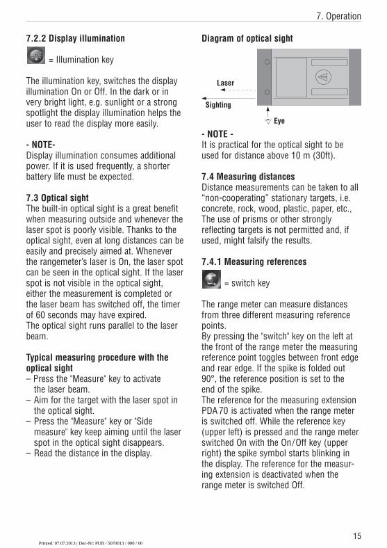
7.3 Optical sightThe built-in optical sight is a great benefitwhen measuring outside and whenever thelaser spot is poorly visible. Thanks to theoptical sight, even at long distances can beeasily and precisely aimed at. Wheneverthe rangemeter’s laser is On, the laser spotcan be seen in the optical sight. If the laserspot is not visible in the optical sight, either the measurement is completed orthe laser beam has switched off, the timerof 60 seconds may have expired.The optical sight runs parallel to the laserbeam.
Typical measuring procedure with theoptical sight– Press the "Measure" key to activate
the laser beam.– Aim for the target with the laser spot in
the optical sight.– Press the "Measure" key or "Side
measure" key keep aiming until the laser spot in the optical sight disappears.
– Read the distance in the display.
Diagram of optical sight
- NOTE -It is practical for the optical sight to beused for distance above 10 m (30ft).
7.4 Measuring distancesDistance measurements can be taken to all“non-cooperating” stationary targets, i.e.concrete, rock, wood, plastic, paper, etc.,The use of prisms or other strongly reflecting targets is not permitted and, ifused, might falsify the results.
7.4.1 Measuring references
= switch key
The range meter can measure distancesfrom three different measuring referencepoints.By pressing the "switch" key on the left atthe front of the range meter the measuringreference point toggles between front edgeand rear edge. If the spike is folded out90°, the reference position is set to the end of the spike.The reference for the measuring extensionPDA 70 is activated when the range meteris switched off. While the reference key(upper left) is pressed and the range meterswitched On with the On/Off key (upperright) the spike symbol starts blinking inthe display. The reference for the measur-ing extension is deactivated when therange meter is switched Off.
Eye
Laser
Sighting
Printed: 07.07.2013 | Doc-Nr: PUB / 5070013 / 000 / 00
7. Operation
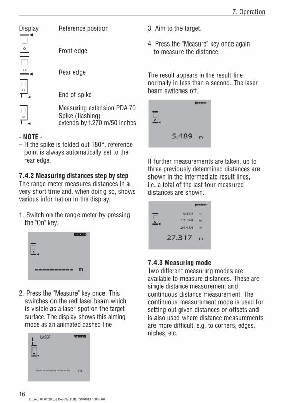
Display Reference position
Front edge
Rear edge
End of spike
Measuring extension PDA 70Spike (flashing)extends by 1.270 m/50 inches
- NOTE -– If the spike is folded out 180°, reference
point is always automatically set to therear edge.
7.4.2 Measuring distances step by stepThe range meter measures distances in avery short time and, when doing so, showsvarious information in the display.
1. Switch on the range meter by pressing the "On" key.
2. Press the "Measure" key once. This switches on the red laser beam which is visible as a laser spot on the target surface. The display shows this aimingmode as an animated dashed line
16
3. Aim to the target.
4. Press the "Measure" key once again to measure the distance.
The result appears in the result line normally in less than a second. The laserbeam switches off.
If further measurements are taken, up tothree previously determined distances areshown in the intermediate result lines, i.e. a total of the last four measured distances are shown.
7.4.3 Measuring modeTwo different measuring modes are available to measure distances. These aresingle distance measurement and continuous distance measurement. Thecontinuous measurement mode is used forsetting out given distances or offsets andis also used where distance measurementsare more difficult, e.g. to corners, edges,niches, etc.
Printed: 07.07.2013 | Doc-Nr: PUB / 5070013 / 000 / 00
7. Operation
17
7.4.3.1 Single distance measurement(Measure key)1.Switch on the laser beam by pressing
the "Measure" key.2.Press the "Measure" key once again.
Generally, the measured distance will be completed in less than a second and shown in the result line.
- NOTE -Alternatively the range meter may be switched on by pressing the On key andthe laser then activated by pressing themeasure key.
7.4.3.2 Continuous measurementPress the "Measure" key for about 2 sec-onds to activate this measuring mode.When doing so, it does not matter whetheror not the range meter is off or the laserbeam is switched on or off. The rangemeter will always switch to continuousmeasurement.During continuous measurement, the dis-tances are updated in the result line byabout 8 to 15 measurements every second.This depends on the reflectivity of the target surface.If the beep signal is switched on, continu-ous measurement is indicated by a Beep. The measuring process is stopped by pressing the "Measure" key once again. Ondoing so, the last valid distance measurement shows in the result line onthe display.
- NOTE -Continuous measurement is possiblewherever distances can be measured. Thisapplies also to functions, such as areasand volumes.
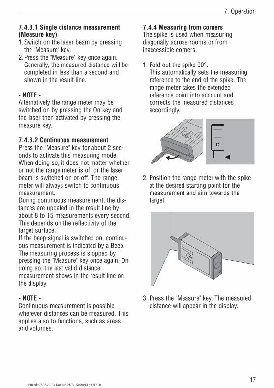
7.4.4 Measuring from cornersThe spike is used when measuring diagonally across rooms or from inaccessible corners.
1. Fold out the spike 90°.This automatically sets the measuringreference to the end of the spike. Therange meter takes the extended reference point into account and corrects the measured distances accordingly.
2. Position the range meter with the spikeat the desired starting point for the measurement and aim towards the target.
3. Press the "Measure" key. The measureddistance will appear in the display.
Printed: 07.07.2013 | Doc-Nr: PUB / 5070013 / 000 / 00
18
7. Operation
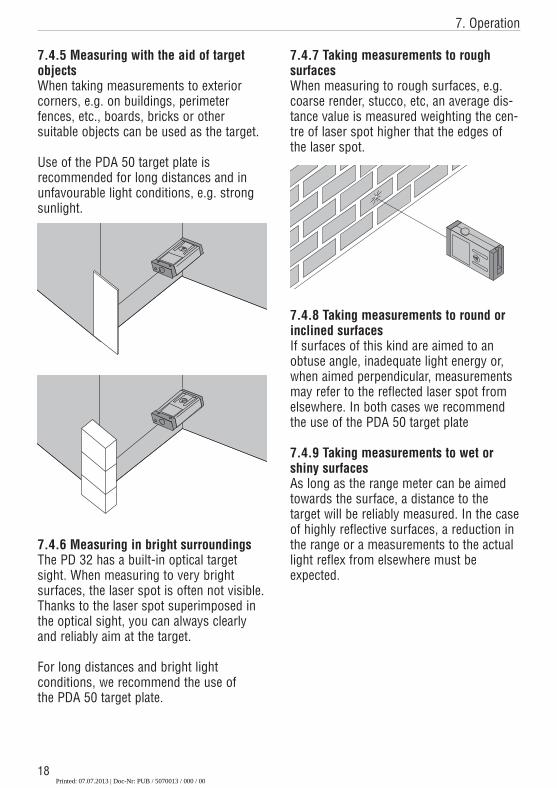
7.4.5 Measuring with the aid of targetobjectsWhen taking measurements to exterior corners, e.g. on buildings, perimeter fences, etc., boards, bricks or other suitable objects can be used as the target.
Use of the PDA 50 target plate is recommended for long distances and in unfavourable light conditions, e.g. strongsunlight.
7.4.6 Measuring in bright surroundingsThe PD 32 has a built-in optical targetsight. When measuring to very bright surfaces, the laser spot is often not visible.Thanks to the laser spot superimposed inthe optical sight, you can always clearlyand reliably aim at the target.
For long distances and bright light conditions, we recommend the use of the PDA 50 target plate.
7.4.7 Taking measurements to rough surfacesWhen measuring to rough surfaces, e.g.coarse render, stucco, etc, an average dis-tance value is measured weighting the cen-tre of laser spot higher that the edges ofthe laser spot.
7.4.8 Taking measurements to round orinclined surfacesIf surfaces of this kind are aimed to anobtuse angle, inadequate light energy or,when aimed perpendicular, measurementsmay refer to the reflected laser spot fromelsewhere. In both cases we recommendthe use of the PDA 50 target plate
7.4.9 Taking measurements to wet orshiny surfacesAs long as the range meter can be aimedtowards the surface, a distance to the target will be reliably measured. In the caseof highly reflective surfaces, a reduction inthe range or a measurements to the actuallight reflex from elsewhere must be expected.
Printed: 07.07.2013 | Doc-Nr: PUB / 5070013 / 000 / 00
19
7. Operation / 8. Applications
7.4.10 Taking measurements to transparent surfacesIt is not possible to measure distances totransparent materials, e.g. liquids, foampolystyrene, etc. This is because light pen-etrates these materials and therefore meas-uring errors may occur. If measurements are taken through glass,measuring errors may also occur.
7.4.11 Measuring ranges
7.4.11.1 Increased distances– Taking measurements in the dark, at
dawn, dusk and to shaded targets or with the front of the range meter shaded,generally leads to an increase of themeasuring range.
– Taking measurements to the PDA 50 tar-ge t plate also results in an increase ofthe measuring range.
7.4.11.2 Reduced distances– Taking measurements in very bright
ambient light, e.g. in sunshine or a verybright spotlight etc, can lead to a reduceddistances.
– Taking measurements through glass orother objects in the target beam can leadto a reduced measuring range.
– Taking measurements to matt green, blueor black, wet or shiny surfaces can leadto a reduced measuring range.
8. Applications and calculationfunctions
The individual steps within all functions aremostly supported, on principle, by graphicson the display.
- NOTE -– Continuous measurement can be used
within all functions where single measurements are possible.
– If measuring errors occur during continuous measurement or if continuous measurement is stopped bypressing the "Measure" key again, the lastvalid distance will be shown.
8.1 Measurement data memoryWhile measuring, the range meter continu-ously saves the measured values and theresults of calculations.
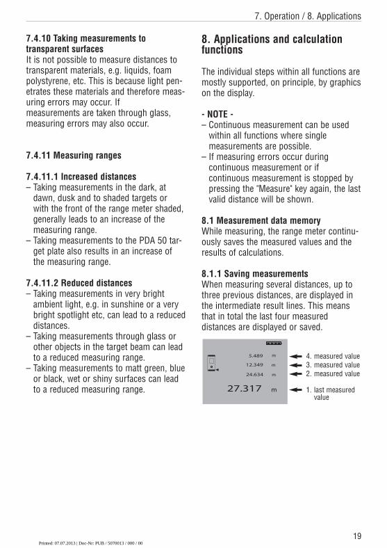
8.1.1 Saving measurementsWhen measuring several distances, up tothree previous distances, are displayed inthe intermediate result lines. This meansthat in total the last four measured distances are displayed or saved.
4. measured value3. measured value2. measured value
1. last measuredvalue
Printed: 07.07.2013 | Doc-Nr: PUB / 5070013 / 000 / 00
20
8. Applications
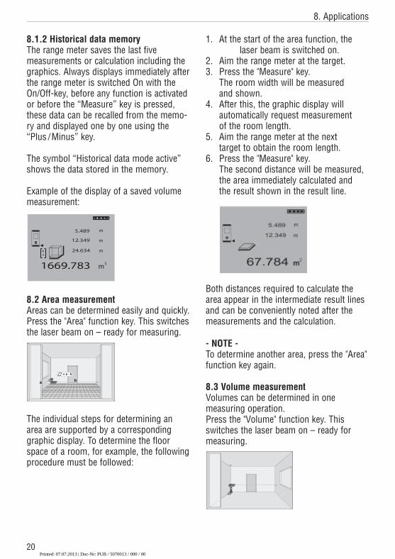
8.1.2 Historical data memoryThe range meter saves the last five measurements or calculation including the graphics. Always displays immediately afterthe range meter is switched On with theOn/Off-key, before any function is activatedor before the “Measure” key is pressed,these data can be recalled from the memo-ry and displayed one by one using the“Plus /Minus” key.
The symbol “Historical data mode active”shows the data stored in the memory.
Example of the display of a saved volumemeasurement:
8.2 Area measurement Areas can be determined easily and quickly.Press the "Area" function key. This switchesthe laser beam on – ready for measuring.
The individual steps for determining anarea are supported by a corresponding graphic display. To determine the floorspace of a room, for example, the followingprocedure must be followed:
a b
= a . b
1. At the start of the area function, the laser beam is switched on.
2. Aim the range meter at the target.3. Press the "Measure" key.
The room width will be measured and shown.
4. After this, the graphic display will automatically request measurement of the room length.
5. Aim the range meter at the next target to obtain the room length.
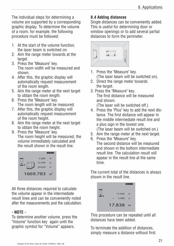
6. Press the "Measure" key.The second distance will be measured, the area immediately calculated and the result shown in the result line.
Both distances required to calculate thearea appear in the intermediate result linesand can be conveniently noted after themeasurements and the calculation.
- NOTE -To determine another area, press the "Area"function key again.
8.3 Volume measurement Volumes can be determined in onemeasuring operation.Press the "Volume" function key. This switches the laser beam on – ready formeasuring.
MEN
x+-I
=
PD 25
Printed: 07.07.2013 | Doc-Nr: PUB / 5070013 / 000 / 00
21
8. Applications
The individual steps for determining a volume are supported by a correspondinggraphic display. To determine the volumeof a room, for example, the following procedure must be followed:
1. At the start of the volume function, the laser beam is switched on.
2. Aim the range meter towards at the target.
3. Press the "Measure" key.The room width will be measured and shown.
4. After this, the graphic display will automatically request measurement of the room length.
5. Aim the range meter at the next targetto obtain the room length.
6. Press the "Measure" key.The room length will be measured.
7. After this, the graphic display will automatically request measurement of the room height.
8. Aim the range meter at the next targetto obtain the room height.
9. Press the "Measure" key.The room height will be measured, thevolume immediately calculated and the result shown in the result line.
All three distances required to calculate the volume appear in the intermediateresult lines and can be conveniently notedafter the measurements and the calculation.
- NOTE -To determine another volume, press the"Volume" function key again until the graphic symbol for “Volume” appears.
8.4 Adding distancesSingle distances can be conveniently added.This is useful for determining door or window openings or to add several partialdistances to form the perimeter.
1. Press the "Measure" key.(The laser beam will be switched on).
2. Direct the range meter towards the target.
3. Press the "Measure" key.The first distance will be measured and shown.(The laser will be switched off.)
4. Press the "Plus" key to add the next dis-tance. The first distance will appear inthe middle intermediate result line anda plus sign in the lowest one.(The laser beam will be switched on.)
5. Aim the range meter at the next target.6. Press the "Measure" key.
The second distance will be measuredand shown in the bottom intermediateresult line. The calculation result willappear in the result line at the sametime.
The current total of the distances is alwaysshown in the result line.
This procedure can be repeated until alldistances have been added.
To terminate the addition of distances, simply measure a distance without first
MEN
x+-I
=
PD 25
MEN
x+-I
=
PD 25
MEN
x+-I
=
PD 25
MENx+-I
=
PD
25
MENx+-I
=
PD
25
MEN
x+-I
=
PD 25
Printed: 07.07.2013 | Doc-Nr: PUB / 5070013 / 000 / 00
22
8. Applications
pressing the "Plus" key. The previous threemeasurement and calculation results willbe in the intermediate displays.
8.5 Subtracting distances Single distances can be conveniently subtracted from each other. This is usefulfor determining, for example, offsets to inaccessible places or the distance fromthe underside of a pipe to the ceiling. To doso, the distance from the floor to theunderside of the pipe is subtracted fromthe distance from the floor to the ceiling. If,additionally, the pipe diameter is deducted,the result is the distance from the top ofthe pipe to the ceiling.
1. Press the "Measure" key.(The laser beam will be switched on.)
2. Aim the range meter at the target.3. Press the "Measure" key.
The first distance will be measured andshown.(The laser beam will switch off.)
4. Press the "Minus" key for subtraction.The first distance will appear in themiddle intermediate result line and aminus sign in the lowest one.(The laser beam will switch on.)
5. Aim the range meter at the next target.6. Press the "Measure" key.
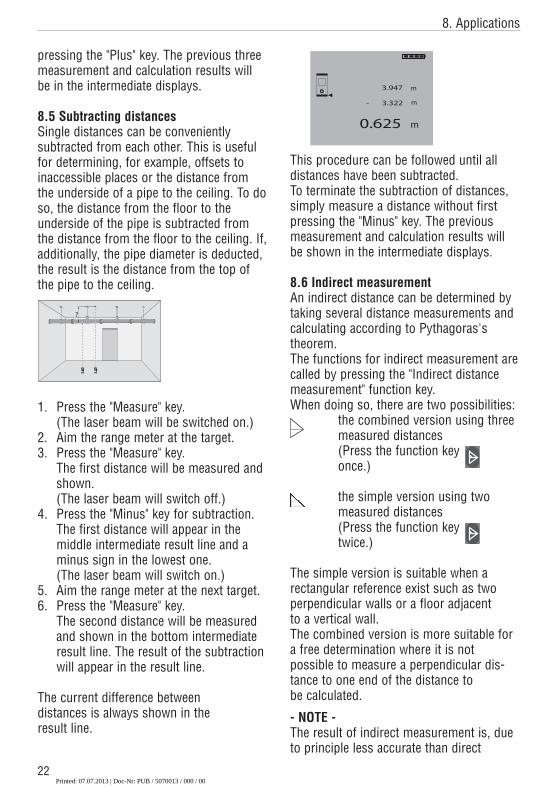
The second distance will be measuredand shown in the bottom intermediateresult line. The result of the subtractionwill appear in the result line.
The current difference between distances is always shown in the result line.
87 954 621 3.0 =
C
I
PD 28
?! +x
87 954 621 3.0 =
C
I
PD 28
?! +x
?
This procedure can be followed until alldistances have been subtracted.To terminate the subtraction of distances, simply measure a distance without firstpressing the "Minus" key. The previousmeasurement and calculation results willbe shown in the intermediate displays.
8.6 Indirect measurementAn indirect distance can be determined bytaking several distance measurements andcalculating according to Pythagoras's theorem.The functions for indirect measurement arecalled by pressing the "Indirect distancemeasurement" function key.When doing so, there are two possibilities:
the combined version using three measured distances(Press the function key once.)
the simple version using two measured distances(Press the function key twice.)
The simple version is suitable when a rectangular reference exist such as twoperpendicular walls or a floor adjacent to a vertical wall.The combined version is more suitable fora free determination where it is not possible to measure a perpendicular dis-tance to one end of the distance to be calculated.
- NOTE -The result of indirect measurement is, dueto principle less accurate than direct
Printed: 07.07.2013 | Doc-Nr: PUB / 5070013 / 000 / 00
23
8. Applications
measurements. To obtain the best possibleresult, attention must be paid to the geom-etry, e.g. right angle and triangle arrangement. The best results are obtained when:
a) the tool is aimed accurately at the endsof the line
b) all points measured are in one singleplane
c) measuring is carried out closer to theobject rather than far away.
8.6.1 Measuring criteriaThe indirect measurement function verifiesthe triangular geometry as the measure-ments are taken. The angle of the trian-gle(s) at the range meter’s position ischecked and must be greater than 10°.Otherwise a double beep indicates an error,the function terminates and all previousmeasurements are lost. The function auto-matically restarts.
The most reliable results are achieved withthe closest offset to the object. Additionallywhen using the combined version (double-triangle), both triangles should be almostthe same size.
8.6.2 Selecting indirect measurementoptionsPressing the "Indirect distance measurement" function key, activates thecombined version first. Pressing the"Indirect distance measurement" functionkey once again, switches to the simple version. Pressing this key a third time,switches from this function back to thenormal display mode.
>10°
>10°
>10°
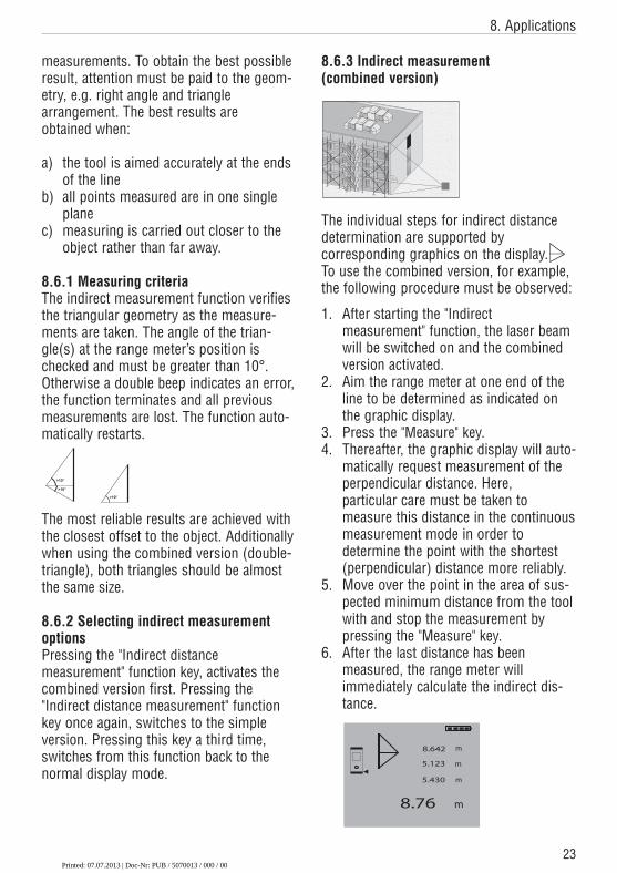
8.6.3 Indirect measurement (combined version)
The individual steps for indirect distancedetermination are supported by corresponding graphics on the display.To use the combined version, for example,the following procedure must be observed:
1. After starting the "Indirect measurement" function, the laser beamwill be switched on and the combinedversion activated.
2. Aim the range meter at one end of theline to be determined as indicated onthe graphic display.
3. Press the "Measure" key.4. Thereafter, the graphic display will auto-
matically request measurement of theperpendicular distance. Here, particular care must be taken to measure this distance in the continuousmeasurement mode in order to determine the point with the shortest(perpendicular) distance more reliably.
5. Move over the point in the area of sus-pected minimum distance from the toolwith and stop the measurement bypressing the "Measure" key.
6. After the last distance has been measured, the range meter will immediately calculate the indirect dis-tance.
90∞
90∞
Printed: 07.07.2013 | Doc-Nr: PUB / 5070013 / 000 / 00
24
8. Applications
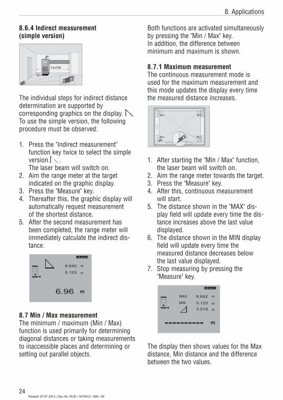
8.6.4 Indirect measurement (simple version)
The individual steps for indirect distancedetermination are supported by corresponding graphics on the display.To use the simple version, the followingprocedure must be observed:
1. Press the "Indirect measurement" function key twice to select the simple version. .The laser beam will switch on.
2. Aim the range meter at the target indicated on the graphic display.
3. Press the "Measure" key.4. Thereafter this, the graphic display will
automatically request measurement of the shortest distance.
5. After the second measurement hasbeen completed, the range meter willimmediately calculate the indirect dis-tance.
8.7 Min / Max measurementThe minimum / maximum (Min / Max)function is used primarily for determiningdiagonal distances or taking measurementsto inaccessible places and determining orsetting out parallel objects.
? m (? ft)
90∞
PD
22
MEN
=
1
x+
-
PD
22
MEN
=
1
x+
-
PD
22
MEN
=
1
x+
-
Both functions are activated simultaneouslyby pressing the "Min / Max" key. In addition, the difference between minimum and maximum is shown.
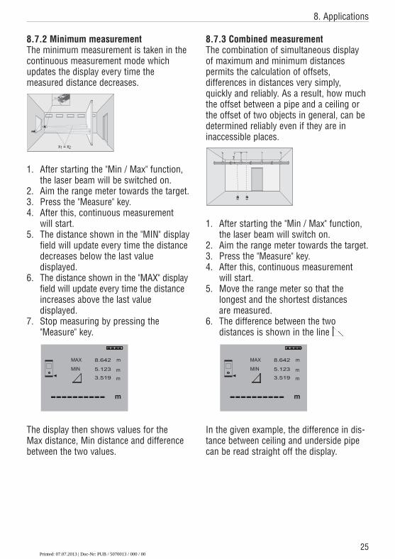
8.7.1 Maximum measurementThe continuous measurement mode isused for the maximum measurement andthis mode updates the display every timethe measured distance increases.
1. After starting the "Min / Max" function,the laser beam will switch on.
2. Aim the range meter towards the target.3. Press the "Measure" key.4. After this, continuous measurement
will start.5. The distance shown in the "MAX" dis-
play field will update every time the dis-tance increases above the last valuedisplayed.
6. The distance shown in the MIN displayfield will update every time the measured distance decreases below the last value displayed.
7. Stop measuring by pressing the"Measure" key.
The display then shows values for the Maxdistance, Min distance and the differencebetween the two values.
90∞
90∞
90∞
90∞
MEN
x+
-I
=
PD 22
LASER
MEN
x+
-I
=
PD
22
LASER
Printed: 07.07.2013 | Doc-Nr: PUB / 5070013 / 000 / 00
25
8. Applications
8.7.2 Minimum measurementThe minimum measurement is taken in thecontinuous measurement mode whichupdates the display every time the measured distance decreases.
1. After starting the "Min / Max" function,the laser beam will be switched on.
2. Aim the range meter towards the target.3. Press the "Measure" key.4. After this, continuous measurement
will start.5. The distance shown in the "MIN" display
field will update every time the distancedecreases below the last value displayed.
6. The distance shown in the "MAX" displayfield will update every time the distanceincreases above the last value displayed.
7. Stop measuring by pressing the"Measure" key.
The display then shows values for the Max distance, Min distance and differencebetween the two values.
x1 = x2
87
95
46
21
3.
0= C
I
PD
28
?!+x
87
95
46
21
3.
0= C
I
PD 28
?!+x
87
4C
PD 28
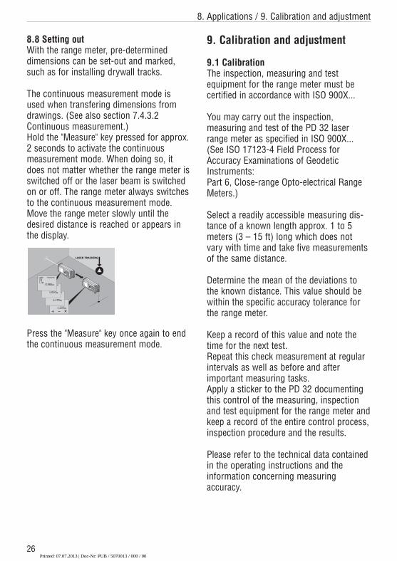
8.7.3 Combined measurementThe combination of simultaneous displayof maximum and minimum distances permits the calculation of offsets, differences in distances very simply, quickly and reliably. As a result, how muchthe offset between a pipe and a ceiling orthe offset of two objects in general, can bedetermined reliably even if they are in inaccessible places.
1. After starting the "Min / Max" function,the laser beam will switch on.
2. Aim the range meter towards the target.3. Press the "Measure" key.4. After this, continuous measurement
will start.5. Move the range meter so that the
longest and the shortest distances are measured.
6. The difference between the two distances is shown in the line
In the given example, the difference in dis-tance between ceiling and underside pipecan be read straight off the display.
87 954 621 3.0 =
C
I
PD 28
?! +x
87 954 621 3.0 =
C
I
PD 28
?! +x
?
Printed: 07.07.2013 | Doc-Nr: PUB / 5070013 / 000 / 00
26
8. Applications / 9. Calibration and adjustment
8.8 Setting out With the range meter, pre-determineddimensions can be set-out and marked,such as for installing drywall tracks.
The continuous measurement mode isused when transfering dimensions fromdrawings. (See also section 7.4.3.2Continuous measurement.)Hold the "Measure" key pressed for approx.2 seconds to activate the continuous measurement mode. When doing so, itdoes not matter whether the range meter isswitched off or the laser beam is switchedon or off. The range meter always switchesto the continuous measurement mode.Move the range meter slowly until the desired distance is reached or appears inthe display.
Press the "Measure" key once again to endthe continuous measurement mode.
9. Calibration and adjustment
9.1 CalibrationThe inspection, measuring and test equipment for the range meter must becertified in accordance with ISO 900X...
You may carry out the inspection, measuring and test of the PD 32 laserrange meter as specified in ISO 900X...(See ISO 17123-4 Field Process forAccuracy Examinations of GeodeticInstruments: Part 6, Close-range Opto-electrical RangeMeters.)
Select a readily accessible measuring dis-tance of a known length approx. 1 to 5meters (3 – 15 ft) long which does notvary with time and take five measurementsof the same distance.
Determine the mean of the deviations tothe known distance. This value should bewithin the specific accuracy tolerance forthe range meter.
Keep a record of this value and note thetime for the next test.Repeat this check measurement at regularintervals as well as before and after important measuring tasks.Apply a sticker to the PD 32 documentingthis control of the measuring, inspectionand test equipment for the range meter andkeep a record of the entire control process,inspection procedure and the results.
Please refer to the technical data containedin the operating instructions and the information concerning measuring accuracy.
Printed: 07.07.2013 | Doc-Nr: PUB / 5070013 / 000 / 00
27
9. Calibration and adjustment / 10. Care and maintenance
9.2 AdjustmentFor optimized adjustment, have the laserrange meter adjusted at a Hilti workshopwhere accurate adjustment of the rangemeter will be confirmed with a calibrationcertificate.
9.3 Hilti calibration serviceWe recommend that you undertake a regular check of the laser range meterthrough the Hilti calibration service in orderto verify its reliability in accordance withstandards and legal requirements.
The Hilti calibration service is available atall times, but a check at least once a year is recommended.
As a part of the Hilti calibration service, itis verified that on the day of the check thespecifications of the range meter complywith the technical information given in theoperating instructions.
If there are deviations from the manufac-turer's information, the range meter will be re-adjusted. After the check and adjustment, a calibration sticker will beapplied to the range meter, and it will beverified in writing in a calibration certificatethat the range meter functions in compliance with the manufacturer's information.
Calibration certificates are always requiredfor companies that have been certifiedaccording to ISO 900X...
Your local Hilti contact / representative willbe pleased to provide further information.
10. Care and maintenance
10.1 Cleaning and drying– Blow dust off the lens.– Do not touch the lens with your fingers.– Use only a clean, soft cloth for cleaning.
If necessary, slightly moisten the clothswith pure alcohol or a little water.
- NOTE -– Do not use any other liquids as these
might damage the plastic parts.– Observe the temperature limits when
storing your equipment. This is particu-larly important in winter or summer,especially if the equipment is kept insidea vehicle (storage temperatures: -30°C to +70°C / -22°F to +158°F).
– Replace damaged parts.
10.2 Storage– Remove the range meter from its case if
it has become wet. Clean the rangemeter, carrying case and accessories.Re-pack the equipment only when it iscompletely dry.
– Check the accuracy of the equipmentbefore it is used after a long period ofstorage or transportation.
– Remove the batteries if the range meteris not going to be used for a consider-able time. The range meter can be damaged by leaking batteries.
10.3 TransportationUse either the original Hilti cardboard boxthe tool was delivered in or packaging ofequivalent quality for transporting or ship-ping your equipment.
- NOTE -Always remove the batteries before shipment.
Printed: 07.07.2013 | Doc-Nr: PUB / 5070013 / 000 / 00
11. Disposal / 12. Manufacturer's warranty – tools
11. Disposal- CAUTION -Improper disposal of the equipment mayhave serious consequences:Burning plastic parts / components generates toxic fumes which may present ahealth hazard.Batteries might explode if damaged orexposed to very high temperatures. Thiscould cause poisoning, burns, acid burns orenvironmental pollution. Careless disposalmight permit unauthorized and improper useof the equipment, possibly leading to seriouspersonal injury, injury to third parties and pol-lution of the environment.
Most of the materials from which Hilti range meters are manufactured can be recycled. A prerequisite for recycling is proper separation of the materials. In many countries, Hilti has already made arrangements for old range meters (and other tools and machines) to be taken back for recycling. Ask the Hilti customer service or your local Hilti representative for further information.
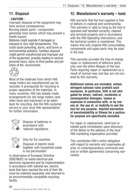
Dispose of batteries in accordance withnational regulations
Only for EU countriesDisposal of electric tools together with household waste is not permissible!
In observance of Euro pean Directive2002/96/EC on waste electrical and electronic equipment and its implementationin accordance with national law, electrictools that have reached the end of their lifemust be collected separately and returned toan environmentally compatible recyclingfacility.
12. Manufacturer's warranty – tools
Hilti warrants that the tool supplied is freeof defects in material and workmanship.This warranty is valid so long as the tool isoperated and handled correctly, cleanedand serviced properly and in accordancewith the Hilti Operating Instructions, andthe technical system is maintained. Thismeans that only original Hilti consumables,components and spare parts may be usedin the tool.
This warranty provides the free-of-chargerepair or replacement of defective partsonly over the entire lifespan of the tool.Parts requiring repair or replacement as aresult of normal wear and tear are not cov-ered by this warranty.
Additional claims are excluded, unlessstringent national rules prohibit suchexclusion. In particular, Hilti is not obli-gated for direct, indirect, incidental orconsequential damages, losses orexpenses in connection with, or by rea-son of, the use of, or inability to use thetool for any purpose. Implied warrantiesof merchantability or fitness for a particu-lar purpose are specifically excluded.
For repair or replacement, send tool orrelated parts immediately upon discoveryof the defect to the address of the localHilti marketing organization provided.
This constitutes Hilti's entire obligationwith regard to warranty and supersedes allprior or contemporaneous comments andoral or written agreements concerning war-ranties.
28Printed: 07.07.2013 | Doc-Nr: PUB / 5070013 / 000 / 00
29
13 FCC statement (applicable in US)
13 FCC statement (applicable in US)
- WARNING -This equipment has been tested and hasbeen found to comply with the limits for aclass B digital device, pursuant to part 15of the FCC rules.These limits are designed to provide reasonable protection against harmfulinterference in a residual installation. This equipment generates, uses, and canradiate radio frequency energy and, if notinstalled and used in accordance with theinstructions, may cause harmful interference to radio communications.However, there is no guarantee that interference will not occur in a particularinstallation. If this equipment does causeharmful interference to radio or televisionreception, which can be determined by turning the equipment on and off, the useris encouraged to try to correct the interference by one or more of the following measures:– Re-orient or re-locate the receiving
antenna.– Increase the separation between the
equipment and receiver.– Connect the equipment to an outlet on a
circuit different from that to which the receiver is connected.
- Consult the dealer or an experienced TV /radio technician for assistance.
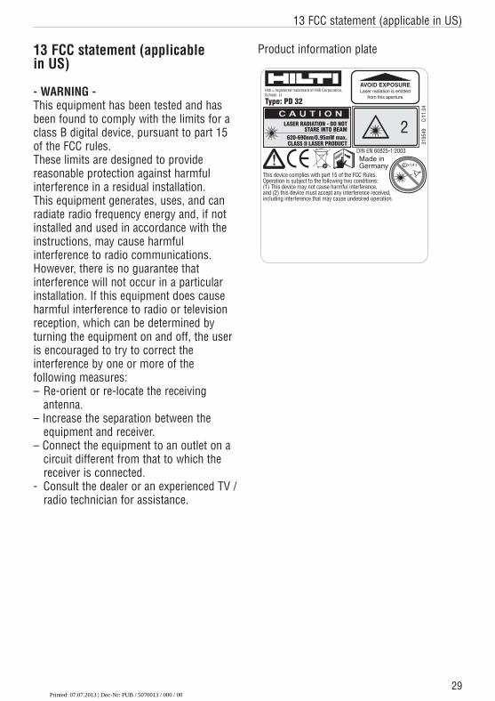
Product information plate
CLASS II LASER PRODUCT620-690nm/0.95mW max.
STARE INTO BEAMLASER RADIATION - DO NOT 2
1/4 s
3195
49
C/1
1.04
This device complies with part 15 of the FCC Rules. Operation is subject to the following two conditions:(1) This device may not cause harmful interference, and (2) this device must accept any interference received,including interference that may cause undesired operation.
AVOID EXPOSURELaser radiation is emitted
from this aperture
Hilti = registered trademark of Hilti Corporation, Schaan, LI
Type: PD 32
Made in Germany
DIN EN 60825-1:2003
Printed: 07.07.2013 | Doc-Nr: PUB / 5070013 / 000 / 00
30
14. EC conformity
14. EC conformity
Designation: Laser range meterType: PD 32Year of design: 2003
In conformance with
We declare, on our own responsibility, thatthis product complies with the followingstandards or standardization documents:EN 50081-1 and EN 61000-6-2 accordingto the stipulations of the directive89/336/EEC.
Hilti Corporation
Matthias GillnerHead BUMeasuring Systems01 / 2005
Dr. Heinz-Joachim SchneiderExecutive Vice PresidentBA Electric Tools &Accessories01 / 2005
Printed: 07.07.2013 | Doc-Nr: PUB / 5070013 / 000 / 00

Hilti CorporationFL-9494 SchaanTel.: +423 / 234 2111Fax: +423 / 234 29 65www.hilti.com
Hilti = registered trademark of Hilti Corp., Schaan W 2906 0306 20-Pos. 1 1 Printed in Liechtenstein © 2006Right of technical and programme changes reserved S. E. & O. 28
2410
/C
Printed: 07.07.2013 | Doc-Nr: PUB / 5070013 / 000 / 00