Embed Size (px)
Citation preview
650150000093927_A
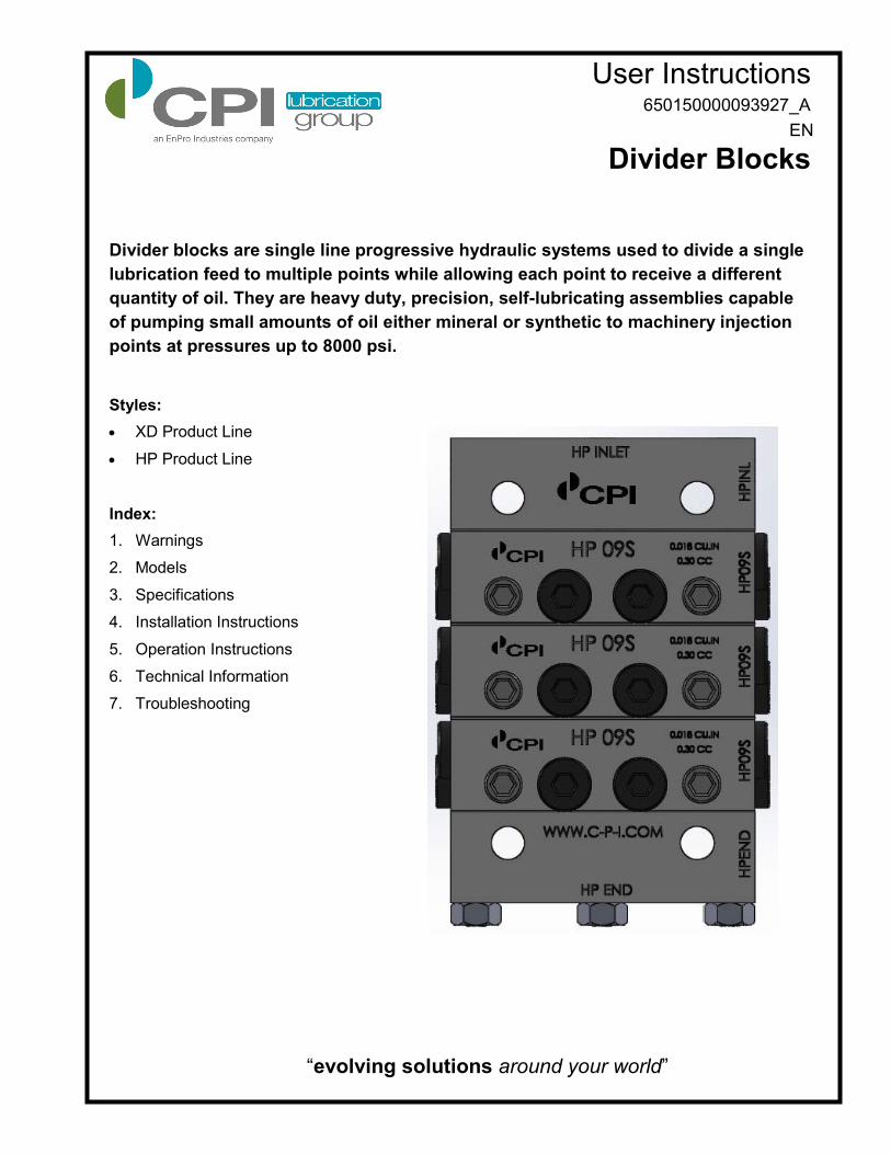
User Instructions
Divider Blocks
Divider blocks are single line progressive hydraulic systems used to divide a single
lubrication feed to multiple points while allowing each point to receive a different
quantity of oil. They are heavy duty, precision, self-lubricating assemblies capable
of pumping small amounts of oil either mineral or synthetic to machinery injection
points at pressures up to 8000 psi.
Styles:
XD Product Line
HP Product Line
Index:
1. Warnings
2. Models
3. Specifications
4. Installation Instructions
5. Operation Instructions
6. Technical Information
7. Troubleshooting
“evolving solutions around your world”
EN
650150000093927_A 2
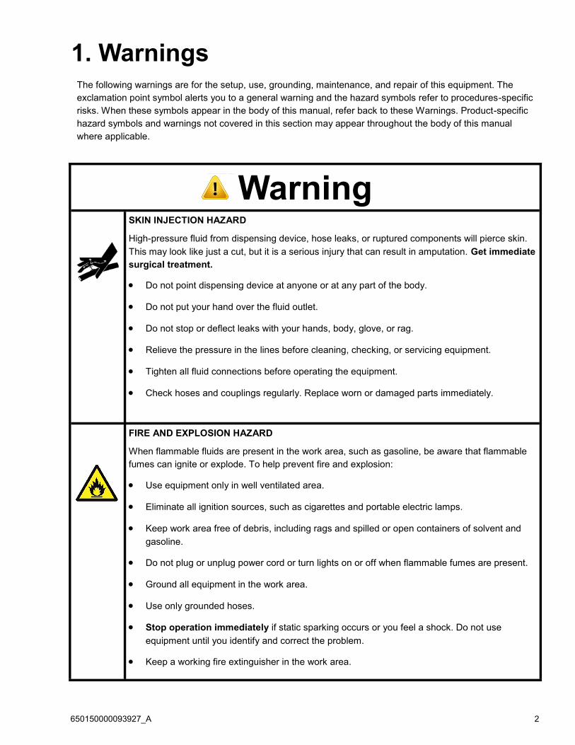
The following warnings are for the setup, use, grounding, maintenance, and repair of this equipment. The
exclamation point symbol alerts you to a general warning and the hazard symbols refer to procedures-specific
risks. When these symbols appear in the body of this manual, refer back to these Warnings. Product-specific
hazard symbols and warnings not covered in this section may appear throughout the body of this manual
where applicable.
1. Warnings
Warning SKIN INJECTION HAZARD
High-pressure fluid from dispensing device, hose leaks, or ruptured components will pierce skin.
This may look like just a cut, but it is a serious injury that can result in amputation. Get immediate
surgical treatment.
Do not point dispensing device at anyone or at any part of the body.
Do not put your hand over the fluid outlet.
Do not stop or deflect leaks with your hands, body, glove, or rag.
Relieve the pressure in the lines before cleaning, checking, or servicing equipment.
Tighten all fluid connections before operating the equipment.
Check hoses and couplings regularly. Replace worn or damaged parts immediately.
FIRE AND EXPLOSION HAZARD
When flammable fluids are present in the work area, such as gasoline, be aware that flammable
fumes can ignite or explode. To help prevent fire and explosion:
Use equipment only in well ventilated area.
Eliminate all ignition sources, such as cigarettes and portable electric lamps.
Keep work area free of debris, including rags and spilled or open containers of solvent and
gasoline.
Do not plug or unplug power cord or turn lights on or off when flammable fumes are present.
Ground all equipment in the work area.
Use only grounded hoses.
Stop operation immediately if static sparking occurs or you feel a shock. Do not use
equipment until you identify and correct the problem.
Keep a working fire extinguisher in the work area.
650150000093927_A 3
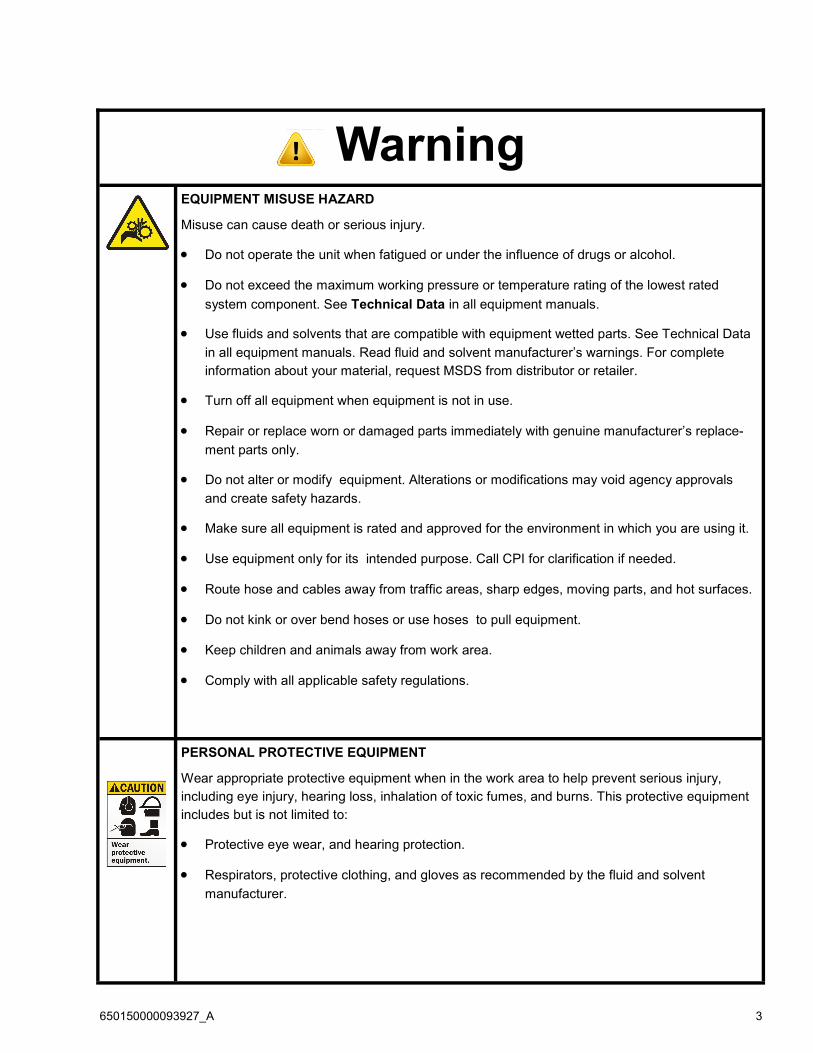
Warning EQUIPMENT MISUSE HAZARD
Misuse can cause death or serious injury.
Do not operate the unit when fatigued or under the influence of drugs or alcohol.
Do not exceed the maximum working pressure or temperature rating of the lowest rated
system component. See Technical Data in all equipment manuals.
Use fluids and solvents that are compatible with equipment wetted parts. See Technical Data
in all equipment manuals. Read fluid and solvent manufacturer’s warnings. For complete
information about your material, request MSDS from distributor or retailer.
Turn off all equipment when equipment is not in use.
Repair or replace worn or damaged parts immediately with genuine manufacturer’s replace-
ment parts only.
Do not alter or modify equipment. Alterations or modifications may void agency approvals
and create safety hazards.
Make sure all equipment is rated and approved for the environment in which you are using it.
Use equipment only for its intended purpose. Call CPI for clarification if needed.
Route hose and cables away from traffic areas, sharp edges, moving parts, and hot surfaces.
Do not kink or over bend hoses or use hoses to pull equipment.
Keep children and animals away from work area.
Comply with all applicable safety regulations.
PERSONAL PROTECTIVE EQUIPMENT
Wear appropriate protective equipment when in the work area to help prevent serious injury,
including eye injury, hearing loss, inhalation of toxic fumes, and burns. This protective equipment
includes but is not limited to:
Protective eye wear, and hearing protection.
Respirators, protective clothing, and gloves as recommended by the fluid and solvent
manufacturer.

650150000093927_A 4
2. Models CPI XD Divider Block Components
Full Part # Part # Description
XD METERING ELEMENTS
6500300000XD06S XD06S XD 06S METERING ELEMENT
6500300000XD06T XD06T XD 06T METERING ELEMENT
6500300000XD09S XD09S XD 09S METERING ELEMENT
6500300000XD09T XD09T XD 09T METERING ELEMENT
6500300000XD12S XD12S XD 12S METERING ELEMENT
6500300000XD12T XD12T XD 12T METERING ELEMENT
6500300000XD15S XD15S XD 15S METERING ELEMENT
6500300000XD15T XD15T XD 15T METERING ELEMENT
6500300000XD18S XD18S XD 18S METERING ELEMENT
6500300000XD18T XD18T XD 18T METERING ELEMENT
6500300000XD21S XD21S XD 21S METERING ELEMENT
6500300000XD21T XD21T XD 21T METERING ELEMENT
6500300000XD24S XD24S XD 24S METERING ELEMENT
6500300000XD24T XD24T XD 24T METERING ELEMENT
6500300000XD30S XD30S XD 30S METERING ELEMENT
6500300000XD30T XD30T XD 30T METERING ELEMENT
XD CROSSPORT BARS
6500300000XDCPL XDCPL XD CROSSPORT BAR LEFT
XD BASE PLATE ASSEMBLIES
6500300000XDBP3 XDBP3 XD 3 SECTION BASE PLATE
6500300000XDBP4 XDBP4 XD 4 SECTION BASE PLATE
6500300000XDBP5 XDBP5 XD 5 SECTION BASE PLATE
6500300000XDBP6 XDBP6 XD 6 SECTION BASE PLATE
XD BASE COMPONENTS
6500300000XDINL XDINL XD INLET BASE
6500300000XDIMD XDIMD XD INTERMEDIATE BASE
6500300000XDEND XDEND XD END BASE
XD TIE RODS
650030000XDTR03 XDTR03 XD TIE ROD 3 SECTION
650030000XDTR04 XDTR04 XD TIE ROD 4 SECTION
650030000XDTR05 XDTR05 XD TIE ROD 5 SECTION
650030000XDTR06 XDTR06 XD TIE ROD 6 SECTION
XD & HP FITTINGS AND PLUGS
65003001827PLUG 1827PLUG 1/8-27 ORB PLUG
65003071620PLUG 71620PLUG 7/16-20 ORB PLUG
65003014NPTPLUG 14NPTPLUG 1/4-18 NPT PLUG, RECESSED HEX
65002000421PROR 421PROR INTEGRAL BASE CHECK VALVE & TUBE FITTING, 1/8-27 ORB
6500300000TRNUT TRNUT TIE ROD NUT

650150000093927_A 5
CPI HP Divider Block Components
Full Part # Part # Description
HP METERING ELEMENTS
6500300000HP06S HP06S HP 06S METERING ELEMENT
6500300000HP06T HP06T HP 06T METERING ELEMENT
6500300000HP09S HP09S HP 09S METERING ELEMENT
6500300000HP09T HP09T HP 09T METERING ELEMENT
6500300000HP12S HP12S HP 12S METERING ELEMENT
6500300000HP12T HP12T HP 12T METERING ELEMENT
6500300000HP15S HP15S HP 15S METERING ELEMENT
6500300000HP15T HP15T HP 15T METERING ELEMENT
6500300000HP18S HP18S HP 18S METERING ELEMENT
6500300000HP18T HP18T HP 18T METERING ELEMENT
6500300000HP21S HP21S HP 21S METERING ELEMENT
6500300000HP21T HP21T HP 21T METERING ELEMENT
6500300000HP24S HP24S HP 24S METERING ELEMENT
6500300000HP24T HP24T HP 24T METERING ELEMENT
6500300000HP30S HP30S HP 30S METERING ELEMENT
6500300000HP30T HP30T HP 30T METERING ELEMENT
HP CROSSPORT BAR
6500300000HPCPL HPCPL HP CROSSPORT BAR LEFT
6500300000HPCPR HPCPR HP CROSSPORT BAR RIGHT
6500300000HPCPB HPCPB HP CROSSPORT BAR BOTH
HP BASE PLATE ASSEMBLIES
6500300000HPBP3 HPBP3 HP 3 SECTION BASE PLATE
6500300000HPBP4 HPBP4 HP 4 SECTION BASE PLATE
6500300000HPBP5 HPBP5 HP 5 SECTION BASE PLATE
6500300000HPBP6 HPBP6 HP 6 SECTION BASE PLATE
6500300000HPBP7 HPBP7 HP 7 SECTION BASE PLATE
HP BASE COMPONENTS
6500300000HPINL HPINL HP INLET BASE
6500300000HPIMD HPIMD HP INTERMEDIATE BASE
6500300000HPEND HPEND HP END BASE
HP TIE RODS
650030000HPTR03 HPTR03 HP TIE ROD 3 SECTION
650030000HPTR04 HPTR04 HP TIE ROD 4 SECTION
650030000HPTR05 HPTR05 HP TIE ROD 5 SECTION
650030000HPTR06 HPTR06 HP TIE ROD 6 SECTION
650030000HPTR07 HPTR07 HP TIE ROD 7 SECTION

650150000093927_A 6
3. Specifications XD Max Working Pressure 8000 psi
HP Max Working Pressure 6000 psi
Dropsa SMX Max Working Pressure 4000 psi
Max Oil Viscosity 8000 SUS (1700 CPS)
Min Oil Viscosity 80 SUS (15 CPS)
*Suitable for Use with Petroleum and Synthetic Base
Lubricants
Fluid Measurement Conversion Data
(NOTE: All measurements are approximate values only)
Number of Drops US Measurement Metric Measurement
1 drop 0.002 cubic inch 0.033 cubic centimeter (cc)
30 drops 0.061 cubic inch 1 cubic centimeter (cc)
500 drops 1 cubic inch 16.39 cubic centimeter (cc)
14,500 drops 1 pint 0.47 Liter
10 drops/minute 1 pint/24 hours 0.47 Liter /24 hours
1 (cc) = 1 mL
Divider Block Element
Outputs
HP/ XD Element
Size Description
Volume per
Output in in³
06T 0.006 twin 0.006
06S 0.006 single 0.012
09T 0.009 twin 0.009
09S 0.009 single 0.018
12T 0.012 twin 0.012
12S 0.012 single 0.024
15T 0.015 twin 0.015
15S 0.015 single 0.030
18T 0.018 twin 0.018
18S 0.018 single 0.036
21T 0.021 twin 0.021
21S 0.021 single 0.042
24T 0.024 twin 0.024
24S 0.024 single 0.048
30T 0.030 twin 0.030
30S 0.030 single 0.060
650150000093927_A 7
The equipment must be grounded to reduce
the risk of static sparking. Static sparking
can cause fumes to ignite or explode.
Grounding provides an escape wire for the
electric current.
4. Installation
4.3 Filtration
We recommend installing a 10 micron high pressure
filter prior to the inlet of the divider block to filter out
any debris that my be in the oil.
4.1 Mounting Divider Blocks Install the master divider block (the first divider block downstream of the pump) as close to the pump as possible. This will allow the operator to adjust the lu-bricator pump while monitoring cycle time of the sys-tem to achieve correct lubrication rates.
Install secondary divider blocks as close as possible to the injection points on the compressor cylinders and rod packing. This procedure eliminates long tub-ing runs from the divider block to the injection points and enables the operator to easily inspect the system for tubing leaks.
Mount all divider blocks parallel to the floor. This allows complete purging of air from the system and makes it easier to install straight and plumb tubing runs. (See Fig.1)
Avoid installing the divider blocks in locations that prevent easy access for preventative mainte-nance or replacement.
The indicator port plugs on the front of the divider blocks should be easily accessed for trouble shooting the system for blockage and for ease of replacement.
The divider blocks may be mounted directly to the compressor frame, if the surface can be drilled and tapped. When mounting the divider blocks directly to the cylinder. DO NOT use long drill bits that can penetrate through the inside wall of the compressor cylinder or frame.
Mount all divider blocks on a flat surface wher-ever possible. Mounting to an uneven surface may cause distortion in the piston bores and cre-ate premature wear or failure.
Use properly sized bolts for mounting the divider blocks to the compressor frame.
Use divider block mounting brackets in areas that require the divider block to be raised from the mounting surface to enable reliable tubing instal-lation. CPI has several styles of mounting brack-ets to ensure correct mounting of the divider blocks.
CAUTION: When using a mounting plate that must be welded in place NEVER weld on a mounting place with the divider block installed or with any electronic equipment connected to the skid or compressor (no-flow shutdown devices included). Heat or sparking generated during welding will permanently damage the divider blocks and any electronic equipment con-nected.
Install all divider block assemblies in an area on
Divider Block Not Mounted Parallel to Floor
INCORRECT MOUNTING
Divider Block Mounted Parallel to Floor
CORRECT MOUNTING
Fig.1
the compressor to avoid damage from debris or dropped objects.
Install the tubing on the compressor frame away from common areas that must be accessed for maintenance and out of areas commonly used for stepping or where there is the possibility of dam-age from debris or dropped objects.
Keep all multiple tubing rungs from secondary divider blocks as short as possible to reduce the total lubricant volume held in the lines to the injec-tion points.
4.2 Grounding
Ensure the Divider Block is properly grounded.

650150000093927_A 8
5.3 Pressure Relief Procedure
1. Stop lube pump.
2. If installed, close oil supply valve located up-stream from pump.
3. If installed, open drain valve located down-stream from pump.
4. Slowly crack open fluid line fittings to relieve pressure from system
5.1 Purging Air From the
System 1. Once the system is installed the first step is to
fully prime the system with fresh oil and then purge all air from the system.
2. Ensure that the main oil supply is connected and then begin the process of purging the complete system of air, including the divider block.
3. After maintenance or before compressor start-up loosen the tubing connections at the inlet of the master divider block, cylinder and packing gland injection points. If there are secondary divider blocks, loosen tubing connections at the inlet of the secondary divider blocks.
4. If a purge port is available at the pump head connect the purge gun (see fig. 2). If no purge port is available, remove the tubing from the discharge side of the pump and connect the purge gun to the tubing.
5. Pump clean oil common to the system into the tubing line until there are no air bubbles observed flowing from the tubing connection at the inlet of the master divider block. Always hold purge gun in a vertical position to eliminate pumping air into the system.
6. Tighten the tubing connection at the inlet of the master divider block while oil is still flowing.
5. Operation
This equipment stays pressurized until pressure is manually relieved. To help prevent serious injury from pressurized fluid, such as skin injection, splashing fluid and moving parts, follow the Pres-sure Relief Procedure below when you stop pump-ing and before cleaning, checking or servicing the equipment.
7. Continue to operate the purge gun until no air bubbles are observed flowing from the tubing connection at the inlet of the secondary divider block.
8. Tighten the tubing connection at the inlet of the secondary divider block while oil is still flowing.
9. Continue to operate the purge gun until no air bubbles are observed flowing from the tubing connections at the cylinder or packing gland injection points.
10. Tighten the tubing connections at the cylinder and packing gland injection points while oil is still flowing.
5.2 Checking Divider Block
Operation Once this process is complete the system can be tested. If the system is crank driven the compressor needs to be started and the lube rate set to the desired cycle time. To do this the feed pump will have to be adjusted, please see the pump adjustment process in the pump operation manual.
Divider block system lube rates are provided in the form of a cycle time. This is the amount of time required for the complete divider block assembly to complete one full cycle, an injection of oil at every point on the master block. In order to set this rate a cycle indicator must be installed, either digital our visual. The cycle time must be observed and the pump adjusted accordingly until the design or break in cycle time is achieved.
Fig.2
Fig. 2
650150000093927_A 9
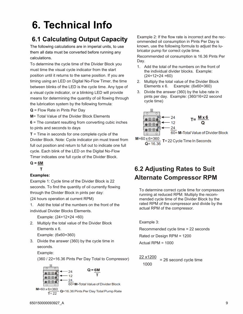
6.1 Calculating Output Capacity
6. Technical Info
The following calculations are in imperial units, to use
them all data must be converted before running any
calculations.
To determine the cycle time of the Divider Block you
must time the visual cycle indicator from the start
position until it returns to the same position. If you are
timing using an LED on Digital No-Flow Timer, the time
between blinks of the LED is the cycle time. Any type of
a visual cycle indicator, or a blinking LED will provide
means for determining the quantity of oil flowing through
the lubrication system by the following formula:
Q = Flow Rate in Pints Per Day
M= Total Value of the Divider Block Elements
6 = The constant resulting from converting cubic inches
to pints and seconds to days
T = Time in seconds for one complete cycle of the
Divider Block. Note: Cycle indicator pin must travel from
full out position and return to full out to indicate one full
cycle. Each blink of the LED on the Digital No-Flow
Timer indicates one full cycle of the Divider Block.
Q = 6M
T
Examples:
Example 1: Cycle time of the Divider Block is 22
seconds. To find the quantity of oil currently flowing
through the Divider Block in pints per day:
(24 hours operation at current RPM)
1. Add the total of the numbers on the front of the
individual Divider Blocks Elements.
Example: (24+12+24 =60)
2. Multiply the total value of the Divider Block
Elements x 6.
Example: (6x60=360)
3. Divide the answer (360) by the cycle time in
seconds.
Example:
(360 / 22=16.36 Pints Per Day Total to Compressor)
Example 2: If the flow rate is incorrect and the rec-ommended oil consumption in Pints Per Day is known, use the following formula to adjust the lu-bricator pump for correct cycle time.
Recommended oil consumption is 16.36 Pints Per Day.
1. Add the total of the numbers on the front of the individual divider blocks. Example: (24+12+24 =60)
2. Multiply the total value of the Divider Block Elements x 6. Example: (6x60=360)
3. Divide the answer (360) by the lube rate in pints per day. Example: (360/16=22 second cycle time)
To determine correct cycle time for compressors running at reduced RPM: Multiply the recom-mended cycle time of the Divider Block by the rated RPM of the compressor and divide by the actual RPM of the compressor.
Example 3:
Recommended cycle time = 22 seconds
Rated or Design RPM = 1200
Actual RPM = 1000
22 x1200
1000
6.2 Adjusting Rates to Suit
Alternate Compressor RPM
= 26 second cycle time
650150000093927_A 10
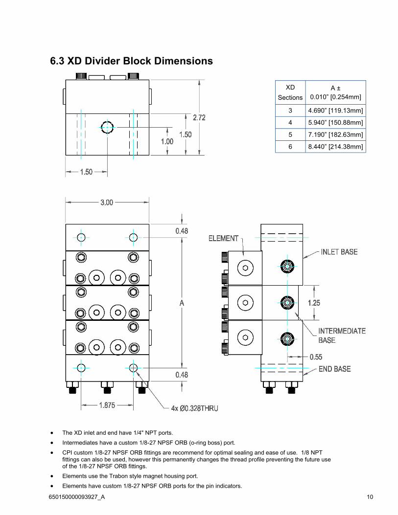
6.3 XD Divider Block Dimensions
XD
Sections
A ±
0.010” [0.254mm]
3 4.690” [119.13mm]
4 5.940” [150.88mm]
5 7.190” [182.63mm]
6 8.440” [214.38mm]
The XD inlet and end have 1/4" NPT ports.
Intermediates have a custom 1/8-27 NPSF ORB (o-ring boss) port.
CPI custom 1/8-27 NPSF ORB fittings are recommend for optimal sealing and ease of use. 1/8 NPT
fittings can also be used, however this permanently changes the thread profile preventing the future use of the 1/8-27 NPSF ORB fittings.
Elements use the Trabon style magnet housing port.
Elements have custom 1/8-27 NPSF ORB ports for the pin indicators.

650150000093927_A 11
HP
Sections
A ±
0.010” [0.254mm]
3 3.375” [85.72mm]
4 4.300” [109.22mm]
5 5.225” [132.72mm]
6 6.150” [156.21mm]
7 7.075” [179.71mm]
6.4 HP Divider Block Dimensions
The HP inlet and end have a custom 1/8-27 NPSF ORB (o-ring boss) port.
Intermediates have a custom 1/8-27 NPSF ORB (o-ring boss) port.
CPI custom 1/8-27 NPSF ORB fittings are recommend for optimal sealing and ease of use. 1/8 NPT
fittings can also be used, however this permanently changes the thread profile preventing the future use of the 1/8-27 NPSF ORB fittings.
Elements use the Trabon style magnet housing port.
Elements have custom 1/8-27 NPSF ORB ports for the pin indicators.
650150000093927_A 12
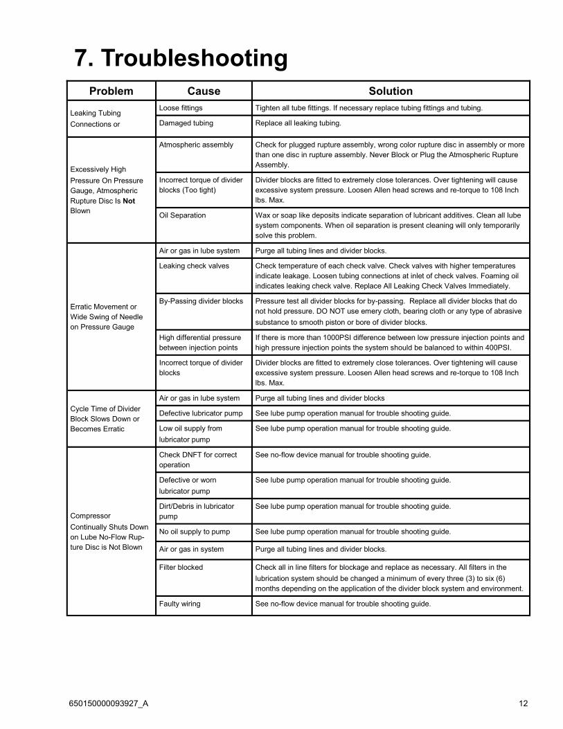
7. Troubleshooting
Problem Cause Solution
Leaking Tubing
Connections or
Loose fittings Tighten all tube fittings. If necessary replace tubing fittings and tubing.
Damaged tubing Replace all leaking tubing.
Excessively High
Pressure On Pressure
Gauge, Atmospheric
Rupture Disc Is Not
Blown
Atmospheric assembly Check for plugged rupture assembly, wrong color rupture disc in assembly or more
than one disc in rupture assembly. Never Block or Plug the Atmospheric Rupture
Assembly.
Incorrect torque of divider
blocks (Too tight)
Divider blocks are fitted to extremely close tolerances. Over tightening will cause
excessive system pressure. Loosen Allen head screws and re-torque to 108 Inch
lbs. Max.
Oil Separation Wax or soap like deposits indicate separation of lubricant additives. Clean all lube
system components. When oil separation is present cleaning will only temporarily
solve this problem.
Erratic Movement or
Wide Swing of Needle
on Pressure Gauge
Air or gas in lube system Purge all tubing lines and divider blocks.
Leaking check valves Check temperature of each check valve. Check valves with higher temperatures
indicate leakage. Loosen tubing connections at inlet of check valves. Foaming oil
indicates leaking check valve. Replace All Leaking Check Valves Immediately.
By-Passing divider blocks Pressure test all divider blocks for by-passing. Replace all divider blocks that do
not hold pressure. DO NOT use emery cloth, bearing cloth or any type of abrasive
substance to smooth piston or bore of divider blocks.
High differential pressure
between injection points
If there is more than 1000PSI difference between low pressure injection points and
high pressure injection points the system should be balanced to within 400PSI.
Incorrect torque of divider
blocks
Divider blocks are fitted to extremely close tolerances. Over tightening will cause
excessive system pressure. Loosen Allen head screws and re-torque to 108 Inch
lbs. Max.
Cycle Time of Divider
Block Slows Down or
Becomes Erratic
Air or gas in lube system Purge all tubing lines and divider blocks
Defective lubricator pump See lube pump operation manual for trouble shooting guide.
Low oil supply from
lubricator pump
See lube pump operation manual for trouble shooting guide.
Compressor
Continually Shuts Down
on Lube No-Flow Rup-
ture Disc is Not Blown
Check DNFT for correct
operation
See no-flow device manual for trouble shooting guide.
Defective or worn
lubricator pump
See lube pump operation manual for trouble shooting guide.
Dirt/Debris in lubricator
pump
See lube pump operation manual for trouble shooting guide.
No oil supply to pump See lube pump operation manual for trouble shooting guide.
Air or gas in system Purge all tubing lines and divider blocks.
Filter blocked Check all in line filters for blockage and replace as necessary. All filters in the
lubrication system should be changed a minimum of every three (3) to six (6)
months depending on the application of the divider block system and environment.
Faulty wiring See no-flow device manual for trouble shooting guide.

650150000093927_A 13
Problem Cause Solution
Atmospheric Rupture
Disc is Blown.
Compressor is Down
Air or gas in lube system Purge all tubing lines and divider blocks.
Nut on atmospheric rupture
assembly over tightened
Install new rupture disc and hand tighten nut on rupture assembly. If torque wrench
is available torque nut to 36 inch pounds max. If torque wrench is not available hand
tighten and tighten with end wrench 1/16th turn. Do not over tighten nut. Over
tightening nut on rupture assembly cuts into aluminum rupture disc causing disc to
blow out at lower pressures.
Crushed tubing Make a visual inspection of the system and check for crushed tubing lines. Correct
as needed
Defective tubing fitting Use purge gun to pump oil through tubing lines to locate blockage.
Correct as needed
Blocked injection point Use purge gun to pump oil into injection points. Oil should flow freely into each
injection point. Correct as needed.
Blocked check valve Use purge gun to pump oil through each check valve. Oil should flow easily through
check valves with less than 160 psi. If plugged replace check valve
Pipe plug improperly
installed in baseplate
Check to ensure all divider blocks required to discharge oil do not have pipe plugs
installed in an outlet designed to disperse oil to an injection point. Divider blocks with
a letter "T" stamped on the front should have (2) two outlets open from the base
plate. Divider blocks with a letter "S" stamped on the front should have (1) one outlet
open on the base plate and one outlet plugged.
Dirt/Debris in divider valve
block
Use purge gun to locate blockage.
Wrong magnet assembly
for proximity switch
Each divider valve manufacturer uses a different magnet assembly. Check for
correct magnet assembly installed on divider valve. Correct as needed.
Divider block assembly is
out of sync
If new divider blocks are installed there is a possibility the pistons are out of sync in
the hydraulic circuit. To correct this problem remove end plugs from one side of each
divider block in the assembly. Using a brass rod push each piston to the opposite
end of the divider block. Replace end plugs and purge the divider block assembly to
check for correct operation.
Oil separation Wax or soap like deposits indicate separation of lubricant additives. Clean all lube
system components. When oil separation is present cleaning will only temporarily
solve this problem.
Atmospheric Rupture
Disc is Blown.
Compressor Does Not
Shut Down.
No-Flow is disconnected Check wiring connections to no-flow and inside of control panel. Correct as needed.
Never Continue to operate the Compressor With the No-Flow Disabled or
Disconnected
Defective No-Flow See no-flow device manual for trouble shooting guide.
DNFT or Proflo Jr. is
connected to control panel
or alarm incorrectly
See no-flow device manual for trouble shooting guide.
Adjust DNFT or Proflo Jr. See no-flow device manual for trouble shooting guide.
650150000093927_A 14
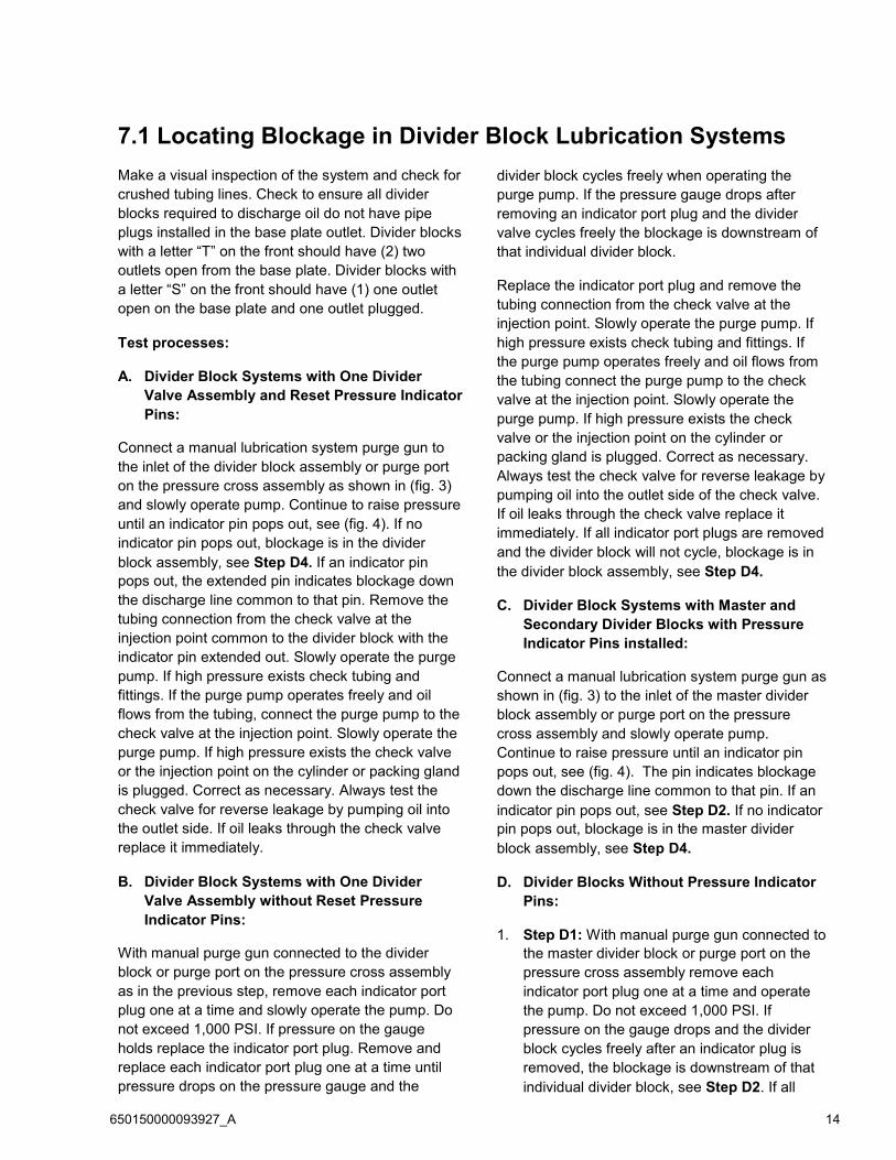
7.1 Locating Blockage in Divider Block Lubrication Systems
Make a visual inspection of the system and check for
crushed tubing lines. Check to ensure all divider
blocks required to discharge oil do not have pipe
plugs installed in the base plate outlet. Divider blocks
with a letter “T” on the front should have (2) two
outlets open from the base plate. Divider blocks with
a letter “S” on the front should have (1) one outlet
open on the base plate and one outlet plugged.
Test processes:
A. Divider Block Systems with One Divider
Valve Assembly and Reset Pressure Indicator
Pins:
Connect a manual lubrication system purge gun to
the inlet of the divider block assembly or purge port
on the pressure cross assembly as shown in (fig. 3)
and slowly operate pump. Continue to raise pressure
until an indicator pin pops out, see (fig. 4). If no
indicator pin pops out, blockage is in the divider
block assembly, see Step D4. If an indicator pin
pops out, the extended pin indicates blockage down
the discharge line common to that pin. Remove the
tubing connection from the check valve at the
injection point common to the divider block with the
indicator pin extended out. Slowly operate the purge
pump. If high pressure exists check tubing and
fittings. If the purge pump operates freely and oil
flows from the tubing, connect the purge pump to the
check valve at the injection point. Slowly operate the
purge pump. If high pressure exists the check valve
or the injection point on the cylinder or packing gland
is plugged. Correct as necessary. Always test the
check valve for reverse leakage by pumping oil into
the outlet side. If oil leaks through the check valve
replace it immediately.
B. Divider Block Systems with One Divider
Valve Assembly without Reset Pressure
Indicator Pins:
With manual purge gun connected to the divider
block or purge port on the pressure cross assembly
as in the previous step, remove each indicator port
plug one at a time and slowly operate the pump. Do
not exceed 1,000 PSI. If pressure on the gauge
holds replace the indicator port plug. Remove and
replace each indicator port plug one at a time until
pressure drops on the pressure gauge and the
divider block cycles freely when operating the
purge pump. If the pressure gauge drops after
removing an indicator port plug and the divider
valve cycles freely the blockage is downstream of
that individual divider block.
Replace the indicator port plug and remove the
tubing connection from the check valve at the
injection point. Slowly operate the purge pump. If
high pressure exists check tubing and fittings. If
the purge pump operates freely and oil flows from
the tubing connect the purge pump to the check
valve at the injection point. Slowly operate the
purge pump. If high pressure exists the check
valve or the injection point on the cylinder or
packing gland is plugged. Correct as necessary.
Always test the check valve for reverse leakage by
pumping oil into the outlet side of the check valve.
If oil leaks through the check valve replace it
immediately. If all indicator port plugs are removed
and the divider block will not cycle, blockage is in
the divider block assembly, see Step D4.
C. Divider Block Systems with Master and
Secondary Divider Blocks with Pressure
Indicator Pins installed:
Connect a manual lubrication system purge gun as
shown in (fig. 3) to the inlet of the master divider
block assembly or purge port on the pressure
cross assembly and slowly operate pump.
Continue to raise pressure until an indicator pin
pops out, see (fig. 4). The pin indicates blockage
down the discharge line common to that pin. If an
indicator pin pops out, see Step D2. If no indicator
pin pops out, blockage is in the master divider
block assembly, see Step D4.
D. Divider Blocks Without Pressure Indicator
Pins:
1. Step D1: With manual purge gun connected to
the master divider block or purge port on the
pressure cross assembly remove each
indicator port plug one at a time and operate
the pump. Do not exceed 1,000 PSI. If
pressure on the gauge drops and the divider
block cycles freely after an indicator plug is
removed, the blockage is downstream of that
individual divider block, see Step D2. If all
650150000093927_A 15
indicator port plugs are removed and the
master divider block will not cycle, blockage is
in this divider block assembly, see Step D4.
2. Step D2: Testing indicates blockage is located
downstream of the Master divider block. If
installed remove the indicator pin or indicator
port plug and connect the purge gun to the
indicator port on the front of the master divider
block that feeds the blocked line. See (fig. 6).
Remove all indicator port plugs in the
secondary divider block assembly. If oil can be
easily pumped through all indicator ports, the
blockage is not in the tubing line or the divider
valve, see Step D3. If oil does not flow freely
through the indicator ports the blockage is in
the secondary divider block or its supply line.
Disconnect the tubing line from the inlet of the
secondary divider block assembly and pump
the purge gun to verify blockage is not in the
tubing line. If blockage is in the divider block
assembly, see Step D4.
3. Step D3: Remove indicator port plugs or
indicator pins from the secondary divider
blocks. Connect purge gun to each indicator
port of the secondary divider blocks one at a
time and slowly operate pump as shown in (fig.
7). If high pressure exists in any port tested
blockage has been located. Check tube,
fittings, check valves, packing gland and
cylinder injection points by pumping oil into
each.
4. Step D4: When testing indicates blockage is in
the divider block, before disassembly, remove
all piston enclosure plugs, see (fig. 8). Without
removing the pistons use a brass rod and
finger pressure only to move each piston back
and forth. If all pistons are moveable, replace
the enclosure plugs and retest the assembly by
pumping oil into the inlet. (Blockage may have
been dislodged and the assembly may be in
working condition without further service.) If
piston is jammed or wax like substance or dirt
is found in the piston bore, the divider block
must be disassembled and cleaned. Before
removing, make a note of divider block
positions on the base from top to bottom, see
(fig. 3). (Example 9T-12T-24T). Working with
one block at a time, remove the piston with a
brass rod. If the piston is stuck, try removing it
in the opposite direction. The piston may have
to be forced out by lightly tapping it with a brass
rod only. Do not use any type of hard metal
object to remove the piston. After removal,
thoroughly wash the piston and divider block
with a clean suitable solvent. Blow out all ports
in the divider block and use a small piece of
wire to clean out all passages. Inspect divider
block bore and piston for scratches or score
marks. If either of these are damaged a new
divider block must be installed. The final step is
to thoroughly clean the base sections and blow
out all ports with compressed air.
Caution: DO NOT use emery cloth, bearing
cloth or any type of abrasive substance to clean
or smooth any piston or bore. To do so will
cause the divider block to bypass and can
cause extensive damage to compressor
components. Pistons are precision fitted to
each bore to extremely close tolerances and
cannot be turned end for end or interchanged
with other pistons.
After entire divider block assembly has been
cleaned, inspected and all blocks and pistons
appear in good condition, lubricate and
reassemble, positioning the divider blocks on the
base in their original order as per notes. Make sure
all pistons slide smoothly and fit snugly in divider
block bores. After assembly, test for proper
operation and purge the system with a purge gun
using oil common to the system. To insure proper
operation of the divider block system, it is
absolutely necessary that all tubing and
components be filled with clean oil common to the
system. All air must be purged from tubing and
components before start-up. See Section 5.1
“Purging Air From the System” for instruction.

650150000093927_A 16
Locating Blockage in Divider Block lubrication systems
3
4
5
4

650150000093927_A 17
6
7
650150000093927_A 18
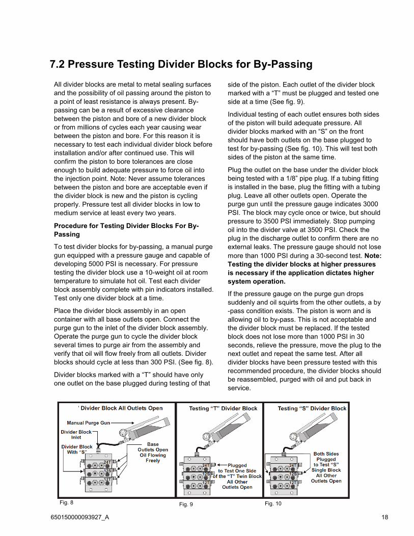
7.2 Pressure Testing Divider Blocks for By-Passing
All divider blocks are metal to metal sealing surfaces
and the possibility of oil passing around the piston to
a point of least resistance is always present. By-
passing can be a result of excessive clearance
between the piston and bore of a new divider block
or from millions of cycles each year causing wear
between the piston and bore. For this reason it is
necessary to test each individual divider block before
installation and/or after continued use. This will
confirm the piston to bore tolerances are close
enough to build adequate pressure to force oil into
the injection point. Note: Never assume tolerances
between the piston and bore are acceptable even if
the divider block is new and the piston is cycling
properly. Pressure test all divider blocks in low to
medium service at least every two years.
Procedure for Testing Divider Blocks For By-
Passing
To test divider blocks for by-passing, a manual purge
gun equipped with a pressure gauge and capable of
developing 5000 PSI is necessary. For pressure
testing the divider block use a 10-weight oil at room
temperature to simulate hot oil. Test each divider
block assembly complete with pin indicators installed.
Test only one divider block at a time.
Place the divider block assembly in an open
container with all base outlets open. Connect the
purge gun to the inlet of the divider block assembly.
Operate the purge gun to cycle the divider block
several times to purge air from the assembly and
verify that oil will flow freely from all outlets. Divider
blocks should cycle at less than 300 PSI. (See fig. 8).
Divider blocks marked with a “T” should have only
one outlet on the base plugged during testing of that
side of the piston. Each outlet of the divider block
marked with a “T” must be plugged and tested one
side at a time (See fig. 9).
Individual testing of each outlet ensures both sides
of the piston will build adequate pressure. All
divider blocks marked with an “S” on the front
should have both outlets on the base plugged to
test for by-passing (See fig. 10). This will test both
sides of the piston at the same time.
Plug the outlet on the base under the divider block
being tested with a 1/8” pipe plug. If a tubing fitting
is installed in the base, plug the fitting with a tubing
plug. Leave all other outlets open. Operate the
purge gun until the pressure gauge indicates 3000
PSI. The block may cycle once or twice, but should
pressure to 3500 PSI immediately. Stop pumping
oil into the divider valve at 3500 PSI. Check the
plug in the discharge outlet to confirm there are no
external leaks. The pressure gauge should not lose
more than 1000 PSI during a 30-second test. Note:
Testing the divider blocks at higher pressures
is necessary if the application dictates higher
system operation.
If the pressure gauge on the purge gun drops
suddenly and oil squirts from the other outlets, a by
-pass condition exists. The piston is worn and is
allowing oil to by-pass. This is not acceptable and
the divider block must be replaced. If the tested
block does not lose more than 1000 PSI in 30
seconds, relieve the pressure, move the plug to the
next outlet and repeat the same test. After all
divider blocks have been pressure tested with this
recommended procedure, the divider blocks should
be reassembled, purged with oil and put back in
service.
Fig. 8 Fig. 9 Fig. 10

650150000093927_A 19
Prepared By:
4410 Greenbriar Drive ▪ Stafford, Texas 77477 USA
Tel 281.207.4600 ▪ Fax 281.207.4612
Website: www.c-p-i.com