Embed Size (px)
Citation preview
DoP_en_HIT-RE 100 _ 000000002267_anchor.docx
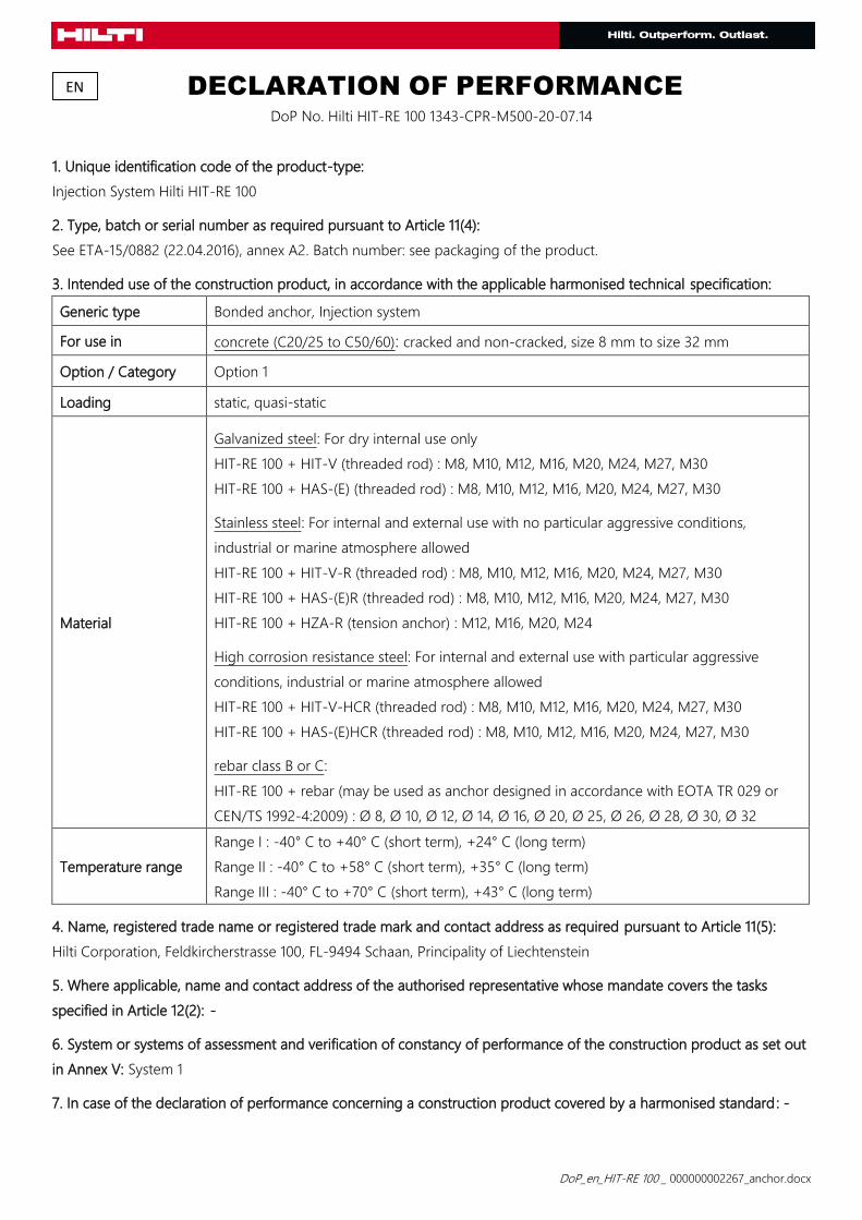
DECLARATION OF PERFORMANCE
DoP No. Hilti HIT-RE 100 1343-CPR-M500-20-07.14
1. Unique identification code of the product-type:
Injection System Hilti HIT-RE 100
2. Type, batch or serial number as required pursuant to Article 11(4):
See ETA-15/0882 (22.04.2016), annex A2. Batch number: see packaging of the product.
3. Intended use of the construction product, in accordance with the applicable harmonised technical specification:
Generic type Bonded anchor, Injection system
For use in concrete (C20/25 to C50/60): cracked and non-cracked, size 8 mm to size 32 mm
Option / Category Option 1
Loading static, quasi-static
Material
Galvanized steel: For dry internal use only
HIT-RE 100 + HIT-V (threaded rod) : M8, M10, M12, M16, M20, M24, M27, M30
HIT-RE 100 + HAS-(E) (threaded rod) : M8, M10, M12, M16, M20, M24, M27, M30
Stainless steel: For internal and external use with no particular aggressive conditions,
industrial or marine atmosphere allowed
HIT-RE 100 + HIT-V-R (threaded rod) : M8, M10, M12, M16, M20, M24, M27, M30
HIT-RE 100 + HAS-(E)R (threaded rod) : M8, M10, M12, M16, M20, M24, M27, M30
HIT-RE 100 + HZA-R (tension anchor) : M12, M16, M20, M24
High corrosion resistance steel: For internal and external use with particular aggressive
conditions, industrial or marine atmosphere allowed
HIT-RE 100 + HIT-V-HCR (threaded rod) : M8, M10, M12, M16, M20, M24, M27, M30
HIT-RE 100 + HAS-(E)HCR (threaded rod) : M8, M10, M12, M16, M20, M24, M27, M30
rebar class B or C:
HIT-RE 100 + rebar (may be used as anchor designed in accordance with EOTA TR 029 or
CEN/TS 1992-4:2009) : Ø 8, Ø 10, Ø 12, Ø 14, Ø 16, Ø 20, Ø 25, Ø 26, Ø 28, Ø 30, Ø 32
Temperature range
Range I : -40° C to +40° C (short term), +24° C (long term)
Range II : -40° C to +58° C (short term), +35° C (long term)
Range III : -40° C to +70° C (short term), +43° C (long term)
4. Name, registered trade name or registered trade mark and contact address as required pursuant to Article 11(5):
Hilti Corporation, Feldkircherstrasse 100, FL-9494 Schaan, Principality of Liechtenstein
5. Where applicable, name and contact address of the authorised representative whose mandate covers the tasks
specified in Article 12(2): -
6. System or systems of assessment and verification of constancy of performance of the construction product as set out
in Annex V: System 1
7. In case of the declaration of performance concerning a construction product covered by a harmonised standard: -
EN
DoP_en_HIT-RE 100 _ 000000002267_anchor.docx
8. In case of the declaration of performance concerning a construction product for which a European Technical
Assessment has been issued:
Deutsches Institut für Bautechnik (DIBt) issued European Technical Assessment ETA-15/0882 (22.04.2016) on the basis of
ETAG 001 Part 1, 5; the notified body 1343-CPR performed third party tasks as set out in Annex V under System 1 and
issued certificate of conformity 1343-CPR-M500-20-07.14.
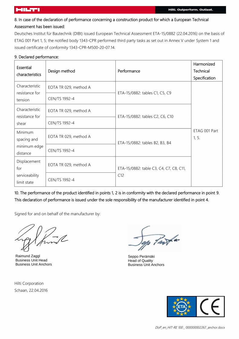
9. Declared performance:
Essential
characteristics Design method Performance
Harmonized
Technical
Specification
Characteristic
resistance for
tension
EOTA TR 029, method A
ETA-15/0882: tables C1, C5, C9
ETAG 001 Part
1, 5.
CEN/TS 1992-4
Characteristic
resistance for
shear
EOTA TR 029, method A
ETA-15/0882: tables C2, C6, C10
CEN/TS 1992-4
Minimum
spacing and
minimum edge
distance
EOTA TR 029, method A
ETA-15/0882: tables B2, B3, B4
CEN/TS 1992-4
Displacement
for
serviceability
limit state
EOTA TR 029, method A ETA-15/0882: table C3, C4, C7, C8, C11,
C12 CEN/TS 1992-4
10. The performance of the product identified in points 1, 2 is in conformity with the declared performance in point 9.
This declaration of performance is issued under the sole responsibility of the manufacturer identified in point 4.
Signed for and on behalf of the manufacturer by:
Hilti Corporation
Schaan, 22.04.2016
Raimund Zaggl Business Unit Head Business Unit Anchors
Seppo Perämäki Head of Quality Business Unit Anchors
Annex 1 DoP_en_HIT-RE 100 _ 000000002267_anchor.docx
Installation:
Use category:
dry or wet concrete or in flooded holes
Drilling technique:
hammer drilling
Overhead installation is admissible.
Anchor installation carried out by appropriately qualified personnel and under the supervision of the person
responsible for technical matters of the site.
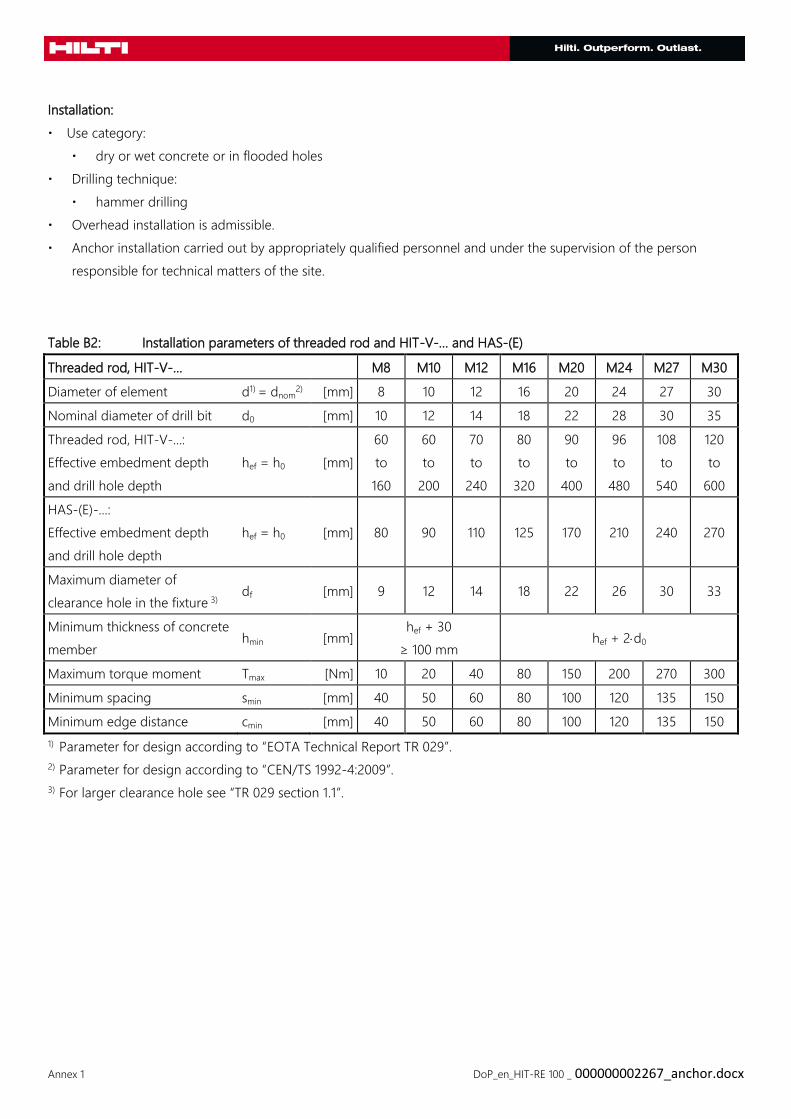
Table B2: Installation parameters of threaded rod and HIT-V-… and HAS-(E)
Threaded rod, HIT-V-… M8 M10 M12 M16 M20 M24 M27 M30
Diameter of element d1) = dnom2) [mm] 8 10 12 16 20 24 27 30
Nominal diameter of drill bit d0 [mm] 10 12 14 18 22 28 30 35
Threaded rod, HIT-V-...:
Effective embedment depth
and drill hole depth
hef = h0 [mm]
60
to
160
60
to
200
70
to
240
80
to
320
90
to
400
96
to
480
108
to
540
120
to
600
HAS-(E)-...:
Effective embedment depth
and drill hole depth
hef = h0 [mm] 80 90 110 125 170 210 240 270
Maximum diameter of
clearance hole in the fixture 3) df [mm] 9 12 14 18 22 26 30 33
Minimum thickness of concrete
member hmin [mm]
hef + 30
≥ 100 mm hef + 2d0
Maximum torque moment Tmax [Nm] 10 20 40 80 150 200 270 300
Minimum spacing smin [mm] 40 50 60 80 100 120 135 150
Minimum edge distance cmin [mm] 40 50 60 80 100 120 135 150
1) Parameter for design according to “EOTA Technical Report TR 029”.
2) Parameter for design according to “CEN/TS 1992-4:2009”.
3) For larger clearance hole see “TR 029 section 1.1”.
Annex 2 DoP_en_HIT-RE 100 _ 000000002267_anchor.docx
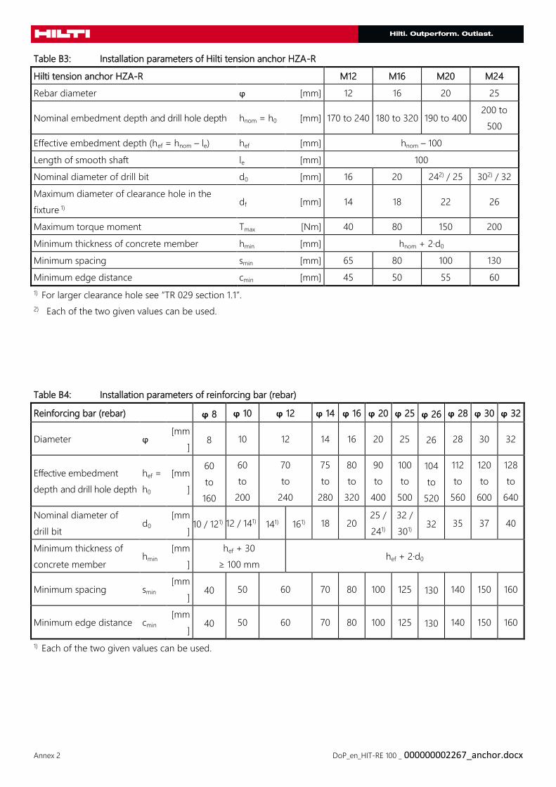
Table B3: Installation parameters of Hilti tension anchor HZA-R
Hilti tension anchor HZA-R M12 M16 M20 M24
Rebar diameter ϕ [mm] 12 16 20 25
Nominal embedment depth and drill hole depth hnom = h0 [mm] 170 to 240 180 to 320 190 to 400 200 to
500
Effective embedment depth (hef = hnom – le) hef [mm] hnom – 100
Length of smooth shaft le [mm] 100
Nominal diameter of drill bit d0 [mm] 16 20 242) / 25 302) / 32
Maximum diameter of clearance hole in the
fixture 1) df [mm] 14 18 22 26
Maximum torque moment Tmax [Nm] 40 80 150 200
Minimum thickness of concrete member hmin [mm] hnom + 2·d0
Minimum spacing smin [mm] 65 80 100 130
Minimum edge distance cmin [mm] 45 50 55 60
1) For larger clearance hole see “TR 029 section 1.1”.
2) Each of the two given values can be used.
Table B4: Installation parameters of reinforcing bar (rebar)
Reinforcing bar (rebar) ϕ 8 ϕ 10 ϕ 12 ϕ 14 ϕ 16 ϕ 20 ϕ 25 ϕ 26 ϕ 28 ϕ 30 ϕ 32
Diameter ϕ [mm
] 8 10 12 14 16 20 25 26 28 30 32
Effective embedment
depth and drill hole depth
hef =
h0
[mm
]
60
to
160
60
to
200
70
to
240
75
to
280
80
to
320
90
to
400
100
to
500
104
to
520
112
to
560
120
to
600
128
to
640
Nominal diameter of
drill bit d0
[mm
] 10 / 121) 12 / 141) 141) 161) 18 20
25 /
241)
32 /
301) 32 35 37 40
Minimum thickness of
concrete member hmin
[mm
]
hef + 30
≥ 100 mm hef + 2·d0
Minimum spacing smin [mm
] 40 50 60 70 80 100 125 130 140 150 160
Minimum edge distance cmin [mm
] 40 50 60 70 80 100 125 130 140 150 160
1) Each of the two given values can be used.
Annex 3 DoP_en_HIT-RE 100 _ 000000002267_anchor.docx
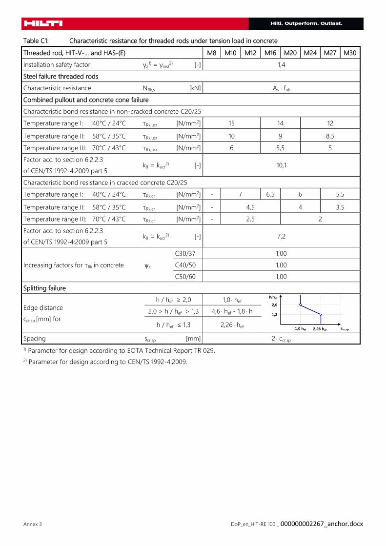
Table C1: Characteristic resistance for threaded rods under tension load in concrete
Threaded rod, HIT-V-… and HAS-(E) M8 M10 M12 M16 M20 M24 M27 M30
Installation safety factor γ21) = γinst
2) [-] 1,4
Steel failure threaded rods
Characteristic resistance NRk,s [kN] As · fuk
Combined pullout and concrete cone failure
Characteristic bond resistance in non-cracked concrete C20/25
Temperature range I: 40°C / 24°C τRk,ucr [N/mm2] 15 14 12
Temperature range II: 58°C / 35°C τRk,ucr [N/mm2] 10 9 8,5
Temperature range III: 70°C / 43°C τRk,ucr [N/mm2] 6 5,5 5
Factor acc. to section 6.2.2.3
of CEN/TS 1992-4:2009 part 5 k8
= kucr2)
[-] 10,1
Characteristic bond resistance in cracked concrete C20/25
Temperature range I: 40°C / 24°C τRk,cr [N/mm2] - 7 6,5 6 5,5
Temperature range II: 58°C / 35°C τRk,cr [N/mm2] - 4,5 4 3,5
Temperature range III: 70°C / 43°C τRk,cr [N/mm2] - 2,5 2
Factor acc. to section 6.2.2.3
of CEN/TS 1992-4:2009 part 5 k8
= kucr2) [-] 7,2
Increasing factors for τRk in concrete c
C30/37 1,00
C40/50 1,00
C50/60 1,00
Splitting failure
Edge distance
ccr,sp [mm] for
h / hef ≥ 2,0 1,0 hef
2,0 > h / hef > 1,3 4,6 hef - 1,8 h
h / hef ≤ 1,3 2,26 hef
Spacing scr,sp [mm] 2 ccr,sp
1) Parameter for design according to EOTA Technical Report TR 029.
2) Parameter for design according to CEN/TS 1992-4:2009.
ccr,sp
h/hef
1,3
2,0
1,0 hef 2,26 hef
Annex 4 DoP_en_HIT-RE 100 _ 000000002267_anchor.docx
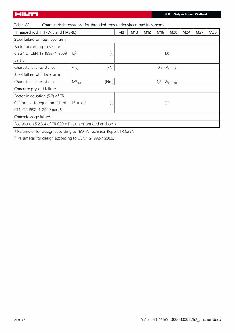
Table C2: Characteristic resistance for threaded rods under shear load in concrete
Threaded rod, HIT-V-… and HAS-(E) M8 M10 M12 M16 M20 M24 M27 M30
Steel failure without lever arm
Factor according to section
6.3.2.1 of CEN/TS 1992-4 :2009
part 5
k22) [-] 1,0
Characteristic resistance VRk,s [kN] 0,5 · As · fuk
Steel failure with lever arm
Characteristic resistance M0Rk,s [Nm] 1,2 · Wel · fuk
Concrete pry-out failure
Factor in equation (5.7) of TR
029 or acc. to equation (27) of
CEN/TS 1992-4 :2009 part 5
k1) = k32) [-] 2,0
Concrete edge failure
See section 5.2.3.4 of TR 029 « Design of bonded anchors »
1) Parameter for design according to “EOTA Technical Report TR 029”.
2) Parameter for design according to CEN/TS 1992-4:2009.
Annex 5 DoP_en_HIT-RE 100 _ 000000002267_anchor.docx
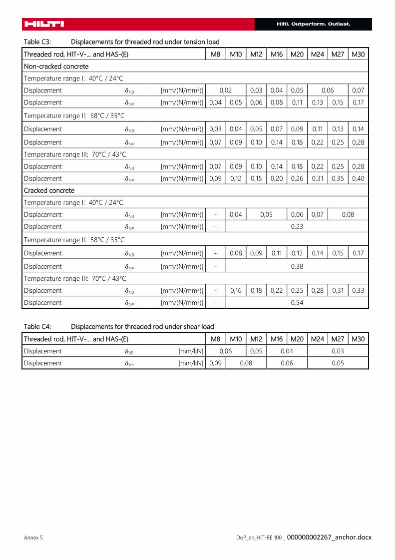
Table C3: Displacements for threaded rod under tension load
Threaded rod, HIT-V-… and HAS-(E) M8 M10 M12 M16 M20 M24 M27 M30
Non-cracked concrete
Temperature range I: 40°C / 24°C
Displacement N0 [mm/(N/mm²)] 0,02 0,03 0,04 0,05 0,06 0,07
Displacement N [mm/(N/mm²)] 0,04 0,05 0,06 0,08 0,11 0,13 0,15 0,17
Temperature range II: 58°C / 35°C
Displacement N0 [mm/(N/mm²)] 0,03 0,04 0,05 0,07 0,09 0,11 0,13 0,14
Displacement N [mm/(N/mm²)] 0,07 0,09 0,10 0,14 0,18 0,22 0,25 0,28
Temperature range III: 70°C / 43°C
Displacement N0 [mm/(N/mm²)] 0,07 0,09 0,10 0,14 0,18 0,22 0,25 0,28
Displacement N [mm/(N/mm²)] 0,09 0,12 0,15 0,20 0,26 0,31 0,35 0,40
Cracked concrete
Temperature range I: 40°C / 24°C
Displacement N0 [mm/(N/mm²)] - 0,04 0,05 0,06 0,07 0,08
Displacement N [mm/(N/mm²)] - 0,23
Temperature range II: 58°C / 35°C
Displacement N0 [mm/(N/mm²)] - 0,08 0,09 0,11 0,13 0,14 0,15 0,17
Displacement N [mm/(N/mm²)] - 0,38
Temperature range III: 70°C / 43°C
Displacement N0 [mm/(N/mm²)] - 0,16 0,18 0,22 0,25 0,28 0,31 0,33
Displacement N [mm/(N/mm²)] - 0,54
Table C4: Displacements for threaded rod under shear load
Threaded rod, HIT-V-… and HAS-(E) M8 M10 M12 M16 M20 M24 M27 M30
Displacement V0 [mm/kN] 0,06 0,05 0,04 0,03
Displacement V [mm/kN] 0,09 0,08 0,06 0,05
Annex 6 DoP_en_HIT-RE 100 _ 000000002267_anchor.docx
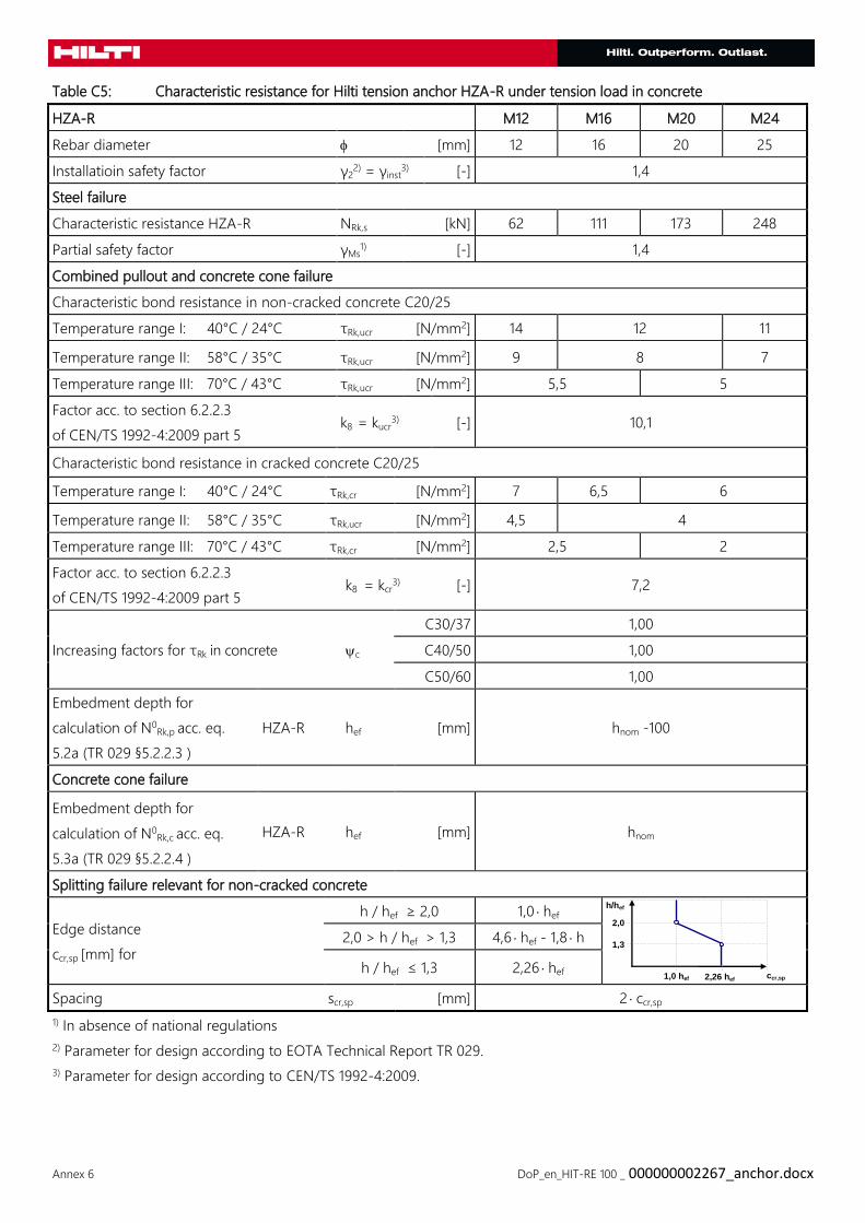
Table C5: Characteristic resistance for Hilti tension anchor HZA-R under tension load in concrete
HZA-R M12 M16 M20 M24
Rebar diameter [mm] 12 16 20 25
Installatioin safety factor γ22) = γinst
3) [-] 1,4
Steel failure
Characteristic resistance HZA-R NRk,s [kN] 62 111 173 248
Partial safety factor γMs1) [-] 1,4
Combined pullout and concrete cone failure
Characteristic bond resistance in non-cracked concrete C20/25
Temperature range I: 40°C / 24°C τRk,ucr [N/mm2] 14 12 11
Temperature range II: 58°C / 35°C τRk,ucr [N/mm2] 9 8 7
Temperature range III: 70°C / 43°C τRk,ucr [N/mm2] 5,5 5
Factor acc. to section 6.2.2.3
of CEN/TS 1992-4:2009 part 5 k8 = kucr
3) [-] 10,1
Characteristic bond resistance in cracked concrete C20/25
Temperature range I: 40°C / 24°C τRk,cr [N/mm2] 7 6,5 6
Temperature range II: 58°C / 35°C τRk,ucr [N/mm2] 4,5 4
Temperature range III: 70°C / 43°C τRk,cr [N/mm2] 2,5 2
Factor acc. to section 6.2.2.3
of CEN/TS 1992-4:2009 part 5 k8 = kcr
3) [-] 7,2
Increasing factors for τRk in concrete c
C30/37 1,00
C40/50 1,00
C50/60 1,00
Embedment depth for
calculation of N0Rk,p acc. eq.
5.2a (TR 029 §5.2.2.3 )
HZA-R hef [mm] hnom -100
Concrete cone failure
Embedment depth for
calculation of N0Rk,c acc. eq.
5.3a (TR 029 §5.2.2.4 )
HZA-R hef [mm] hnom
Splitting failure relevant for non-cracked concrete
Edge distance
ccr,sp [mm] for
h / hef ≥ 2,0 1,0 hef
2,0 > h / hef > 1,3 4,6 hef - 1,8 h
h / hef ≤ 1,3 2,26 hef
Spacing scr,sp [mm] 2 ccr,sp
1) In absence of national regulations
2) Parameter for design according to EOTA Technical Report TR 029.
3) Parameter for design according to CEN/TS 1992-4:2009.
ccr,sp
h/hef
1,3
2,0
1,0 hef 2,26 hef
Annex 7 DoP_en_HIT-RE 100 _ 000000002267_anchor.docx
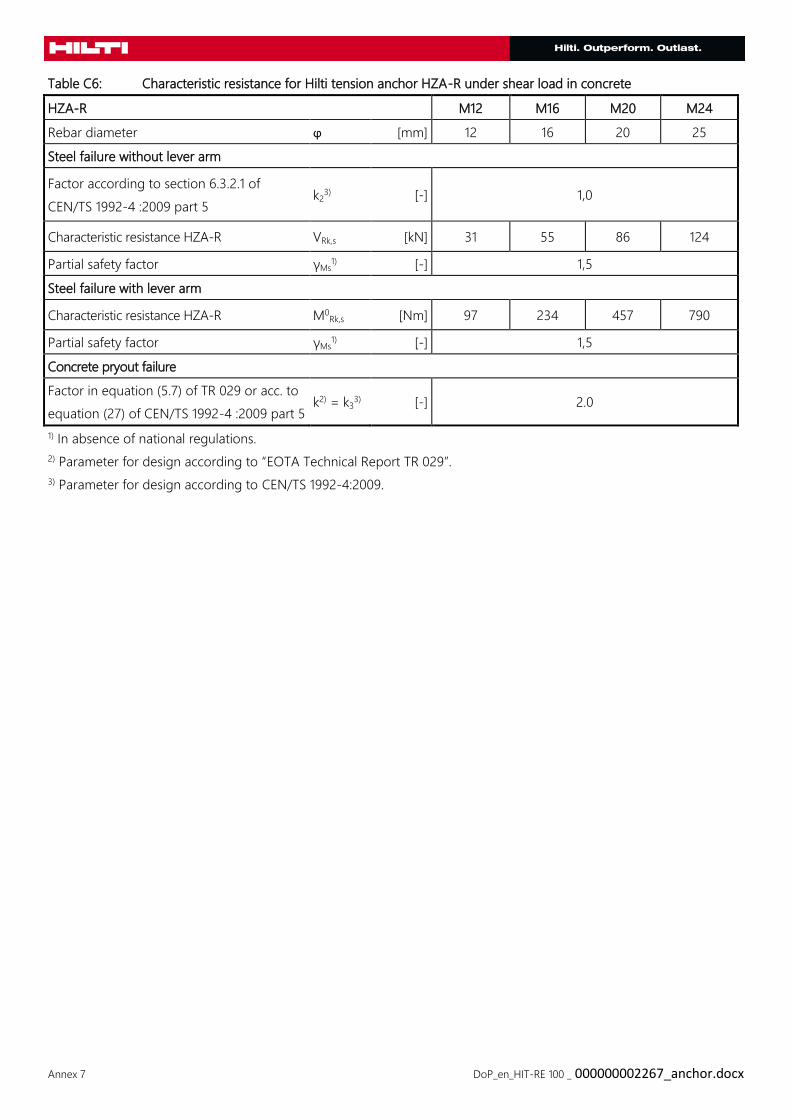
Table C6: Characteristic resistance for Hilti tension anchor HZA-R under shear load in concrete
HZA-R M12 M16 M20 M24
Rebar diameter ϕ [mm] 12 16 20 25
Steel failure without lever arm
Factor according to section 6.3.2.1 of
CEN/TS 1992-4 :2009 part 5 k2
3) [-] 1,0
Characteristic resistance HZA-R VRk,s [kN] 31 55 86 124
Partial safety factor γMs1) [-] 1,5
Steel failure with lever arm
Characteristic resistance HZA-R M0Rk,s [Nm] 97 234 457 790
Partial safety factor γMs1) [-] 1,5
Concrete pryout failure
Factor in equation (5.7) of TR 029 or acc. to
equation (27) of CEN/TS 1992-4 :2009 part 5 k2) = k3
3) [-] 2.0
1) In absence of national regulations.
2) Parameter for design according to “EOTA Technical Report TR 029”.
3) Parameter for design according to CEN/TS 1992-4:2009.
Annex 8 DoP_en_HIT-RE 100 _ 000000002267_anchor.docx
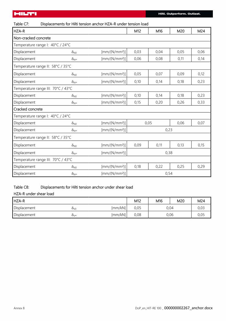
Table C7: Displacements for Hilti tension anchor HZA-R under tension load
HZA-R M12 M16 M20 M24
Non-cracked concrete
Temperature range I: 40°C / 24°C
Displacement N0 [mm/(N/mm²)] 0,03 0,04 0,05 0,06
Displacement N [mm/(N/mm²)] 0,06 0,08 0,11 0,14
Temperature range II: 58°C / 35°C
Displacement N0 [mm/(N/mm²)] 0,05 0,07 0,09 0,12
Displacement N [mm/(N/mm²)] 0,10 0,14 0,18 0,23
Temperature range III: 70°C / 43°C
Displacement N0 [mm/(N/mm²)] 0,10 0,14 0,18 0,23
Displacement N [mm/(N/mm²)] 0,15 0,20 0,26 0,33
Cracked concrete
Temperature range I: 40°C / 24°C
Displacement N0 [mm/(N/mm²)] 0,05 0,06 0,07
Displacement N [mm/(N/mm²)] 0,23
Temperature range II: 58°C / 35°C
Displacement N0 [mm/(N/mm²)] 0,09 0,11 0,13 0,15
Displacement N [mm/(N/mm²)] 0,38
Temperature range III: 70°C / 43°C
Displacement N0 [mm/(N/mm²)] 0,18 0,22 0,25 0,29
Displacement N [mm/(N/mm²)] 0,54
Table C8: Displacements for Hilti tension anchor under shear load
HZA-R under shear load
HZA-R M12 M16 M20 M24
Displacement V0 [mm/kN] 0,05 0,04 0,03
Displacement V [mm/kN] 0,08 0,06 0,05

Annex 9 DoP_en_HIT-RE 100 _ 000000002267_anchor.docx
Table C9: Characteristic resistance for reinforcing bars (rebars) under tension load in concrete
Reinforcing bar (rebar) ϕ 8 ϕ 10 ϕ 12 ϕ 14 ϕ 16 ϕ
20
ϕ
25
ϕ
26
ϕ
28
ϕ
30
ϕ
32
Rebar diameter [mm] 8 10 12 14 16 20 25 26 28 30 32
Installation safety factor γ22) = γinst
3) [-] 1,4
Steel failure rebars
Characteristic resistance NRk,s [kN] 28 43 62 85 111 173 270 292 339 388 442
Combined pullout and concrete cone failure
Characteristic bond resistance in non-cracked concrete C20/25
Temperature range I:
40°C / 24°C τRk,ucr
[N/mm2
] 14 12 11
Temperature range II:
58°C / 35°C τRk,ucr
[N/mm2
] 9 8 7
Temperature range III:
70°C / 43°C τRk,ucr
[N/mm2
] 5,5 5 4,5
Factor acc. to section 6.2.2.3
of CEN/TS 1992-4:2009 part 5 k8 = kucr
3) [-] 10,1
Characteristic bond resistance in cracked concrete C20/25
Temperature range I:
40°C / 24°C τRk,cr
[N/mm2
] - 7 6,5 6 5,5
Temperature range II:
58°C / 35°C τRk,ucr
[N/mm2
] - 4,5 4 3,5
Temperature range III:
70°C / 43°C τRk,cr
[N/mm2
] - 2,5 2,0
Factor acc. to section 6.2.2.3
of CEN/TS 1992-4:2009 part 5 k8 = kcr
3) [-] 7,2
Increasing factors for τRk
in concrete c
C30/37 1,00
C40/50 1,00
C50/60 1,00
Splitting failure relevant for non-cracked concrete
Edge distance
ccr,sp [mm] for
h / hef ≥ 2,0 1,0 hef
2,0 > h / hef > 1,3 4,6 hef - 1,8 h
h / hef ≤ 1,3 2,26 hef
Spacing scr,sp [mm] 2 ccr,sp
1) The characteristic tension resistance NRk,s for rebars that do not fulfil the the requirements acc. DIN 488 shall be
calculated acc. Technical Report TR 029, Equation (5.1)
2) Parameter for design according to EOTA Technical Report TR 029.
3) Parameter for design according to CEN/TS 1992-4:2009.
ccr,sp
h/hef
1,3
2,0
1,0 hef 2,26 hef
Annex 10 DoP_en_HIT-RE 100 _ 000000002267_anchor.docx
Annex 11 DoP_en_HIT-RE 100 _ 000000002267_anchor.docx
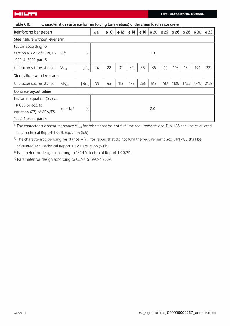
Table C10: Characteristic resistance for reinforcing bars (rebars) under shear load in concrete
Reinforcing bar (rebar) 8 10 12 14 16 20 25 26 28 30 32
Steel failure without lever arm
Factor according to
section 6.3.2.1 of CEN/TS
1992-4 :2009 part 5
k24) [-] 1,0
Characteristic resistance VRk,s [kN] 14 22 31 42 55 86 135 146 169 194 221
Steel failure with lever arm
Characteristic resistance M0Rk,s [Nm] 33 65 112 178 265 518 1012 1139 1422 1749 2123
Concrete pryout failure
Factor in equation (5.7) of
TR 029 or acc. to
equation (27) of CEN/TS
1992-4 :2009 part 5
k3) = k34) [-] 2,0
1) The characteristic shear resistance VRk,s for rebars that do not fulfil the requirements acc. DIN 488 shall be calculated
acc. Technical Report TR 29, Equation (5.5)
2) The characteristic bending resistance M0Rk,s for rebars that do not fulfil the requirements acc. DIN 488 shall be
calculated acc. Technical Report TR 29, Equation (5.6b)
3) Parameter for design according to “EOTA Technical Report TR 029”.
4) Parameter for design according to CEN/TS 1992-4:2009.
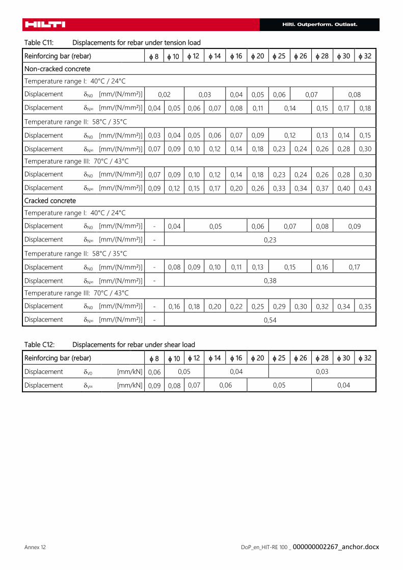
Annex 12 DoP_en_HIT-RE 100 _ 000000002267_anchor.docx
Table C11: Displacements for rebar under tension load
Reinforcing bar (rebar) 8 10 12 14 16 20 25 26 28 30 32
Non-cracked concrete
Temperature range I: 40°C / 24°C
Displacement N0 [mm/(N/mm²)] 0,02 0,03 0,04 0,05 0,06 0,07 0,08
Displacement N [mm/(N/mm²)] 0,04 0,05 0,06 0,07 0,08 0,11 0,14 0,15 0,17 0,18
Temperature range II: 58°C / 35°C
Displacement N0 [mm/(N/mm²)] 0,03 0,04 0,05 0,06 0,07 0,09 0,12 0,13 0,14 0,15
Displacement N [mm/(N/mm²)] 0,07 0,09 0,10 0,12 0,14 0,18 0,23 0,24 0,26 0,28 0,30
Temperature range III: 70°C / 43°C
Displacement N0 [mm/(N/mm²)] 0,07 0,09 0,10 0,12 0,14 0,18 0,23 0,24 0,26 0,28 0,30
Displacement N [mm/(N/mm²)] 0,09 0,12 0,15 0,17 0,20 0,26 0,33 0,34 0,37 0,40 0,43
Cracked concrete
Temperature range I: 40°C / 24°C
Displacement N0 [mm/(N/mm²)] - 0,04 0,05 0,06 0,07 0,08 0,09
Displacement N [mm/(N/mm²)] - 0,23
Temperature range II: 58°C / 35°C
Displacement N0 [mm/(N/mm²)] - 0,08 0,09 0,10 0,11 0,13 0,15 0,16 0,17
Displacement N [mm/(N/mm²)] - 0,38
Temperature range III: 70°C / 43°C
Displacement N0 [mm/(N/mm²)] - 0,16 0,18 0,20 0,22 0,25 0,29 0,30 0,32 0,34 0,35
Displacement N [mm/(N/mm²)] - 0,54
Table C12: Displacements for rebar under shear load
Reinforcing bar (rebar) 8 10 12 14 16 20 25 26 28 30 32
Displacement V0 [mm/kN] 0,06 0,05 0,04 0,03
Displacement V [mm/kN] 0,09 0,08 0,07 0,06 0,05 0,04


![Lenovo C20 Series - GfK Etilizecontent.etilize.com/User-Manual/1032750117.pdf · Machine type: F0B2 [C20-30] F0B3 [C20-05] Lenovo C20 Series User Guide Version 1.0 2014.08 SP40G36984](https://img.pdfslide.us/doc/110x75/5c1dc18409d3f2f93d8b643a/lenovo-c20-series-gfk-machine-type-f0b2-c20-30-f0b3-c20-05-lenovo-c20.jpg)
![for use in non-cracked concrete and masonry MO-P · Metric M8 M10 M12 M16 M20 M24 N Rd Non-cracked concrete [kN] 10.6 14.1 19.6 28.6 44.5 61.6 Maximum recommended tensile load N rec](https://img.pdfslide.us/doc/110x75/6085949c5ec1760c0857fed9/for-use-in-non-cracked-concrete-and-masonry-mo-p-metric-m8-m10-m12-m16-m20-m24-n.jpg)