Embed Size (px)
Citation preview
Chapter 11
Assembly Modeling
After completing this chapter you will be able to:• Insert components into an assembly file.• Create bottom-up assemblies.• Insert components into a product file.• Move and rotate components inside an assembly.• Add constraints to the individual components.• Create top-down assemblies.• Edit assembly designs.• Create the exploded state of an assemblies.
Learning Objectives
Eval
uati
on c
hapt
er.
Logo
n to
ww
w.c
adci
m.c
om f
or m
ore
deta
ils
11-2 CATIA for Designers (Evaluation Chapter F007/004)
Eval
uati
on c
hapt
er.
Logo
n to
ww
w.c
adci
m.c
om f
or m
ore
deta
ils
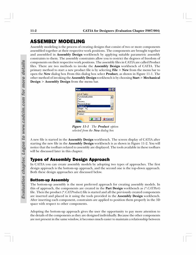
ASSEMBLY MODELINGAssembly modeling is the process of creating designs that consist of two or more componentsassembled together at their respective work positions. The components are brought togetherand assembled in Assembly Design workbench by applying suitable parametric assemblyconstraints to them. The assembly constraints allow you to restrict the degrees of freedom ofcomponents on their respective work positions. The assembly files in CATIA are called Productfiles. There are two methods to invoke the Assembly Design workbench of CATIA. Theprimary method to start a new product file is by selecting File > New from the menu bar toopen the New dialog box From this dialog box select Product, as shown in Figure 11-1. Theother method of invoking the Assembly Design workbench is by choosing Start > MechanicalDesign > Assembly Design from the menu bar.
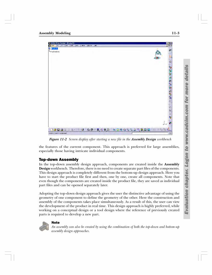
A new file is started in the Assembly Design workbench. The screen display of CATIA afterstarting the new file in the Assembly Design workbench is as shown in Figure 11-2. You willnotice that the toolbars related to assembly are displayed. The tools available in these toolbarswill be discussed later in this chapter.
Types of Assembly Design ApproachIn CATIA you can create assembly models by adopting two types of approaches. The firstdesign approach is the bottom-up approach, and the second one is the top-down approach.Both these design approaches are discussed below.
Bottom-up AssemblyThe bottom-up assembly is the most preferred approach for creating assembly models. Inthis of approach, the components are created in the Part Design workbench as (*.CATPart)file. Then the product (*.CATProduct) file is started and all the previously created componentsare inserted and placed in it using the tools provided in the Assembly Design workbench.After inserting each component, constraints are applied to position them properly in the 3Dspace with respect to other components.
Adopting the bottom-up approach gives the user the opportunity to pay more attention tothe details of the components as they are designed individually. Because the other componentsare not present in the same window, it becomes much easier to maintain a relationship between
Figure 11-1 The Product optionselected from the New dialog box
Assembly Modeling 11-3
Eval
uati
on c
hapt
er.
Logo
n to
ww
w.c
adci
m.c
om f
or m
ore
deta
ils
the features of the current component. This approach is preferred for large assemblies,especially those having intricate individual components.
Top-down AssemblyIn the top-down assembly design approach, components are created inside the AssemblyDesign workbench. Therefore, there is no need to create separate part files of the components.This design approach is completely different from the bottom-up design approach. Here youhave to start the product file first and then, one by one, create all components. Note thateven though the components are created inside the product file, they are saved as individualpart files and can be opened separately later.
Adopting the top-down design approach gives the user the distinctive advantage of using thegeometry of one component to define the geometry of the other. Here the construction andassembly of the components takes place simultaneously. As a result of this, the user can viewthe development of the product in real time. This design approach is highly preferred, whileworking on a conceptual design or a tool design where the reference of previously createdparts is required to develop a new part.
NoteAn assembly can also be created by using the combination of both the top-down and bottom-upassembly design approaches.
Figure 11-2 Screen display after starting a new file in the Assembly Design workbench
11-4 CATIA for Designers (Evaluation Chapter F007/004)
Eval
uati
on c
hapt
er.
Logo
n to
ww
w.c
adci
m.c
om f
or m
ore
deta
ils
Menu: Insert > Existing ComponentToolbar: Product Structure Tools > Existing Component
CREATING BOTTOM-UP ASSEMBLIESAs mentioned earlier, while creating an assembly using the bottom-up approach, thecomponents are created in separate part files and are then inserted into the assembly file.They are assembled at their working position by applying assembly constraints to them. Tocreate an assembly using this approach, it is recommended to insert the first component andfix its position after properly orienting it in the 3D space. The other components can beinserted and positioned with reference to the first component. The method used for placingcomponents inside the product file is discussed below.
Inserting Components in a Product file
To insert the first component in the product file, choose the Existing Componentbutton from the Product Structure Tools toolbar. You are prompted to select acomponent into which the existing component will be inserted. You need to select
Product1 from the Specification Tree. After you do so, the File Selection dialog box isdisplayed. Browse the location where the part files are saved and double-click on thecomponent to be inserted; the component will be inserted in the current product file. Youwill notice a new entry in the Specification Tree, which is referred to as Part1. Part1 is adefault part number assigned by the software to the component. A default part number isassigned to each component that is inserted in the assembly, unless it is changed by the user.Inside the assembly, the components are referred to by their part number and not by theirfile name. The process of changing the part number of the component is discussed later inthis chapter. It is always recommended to fix the first component using the Fix constraintafter inserting. The method of applying the Fix constraint to the component is discussedlater in the chapter.
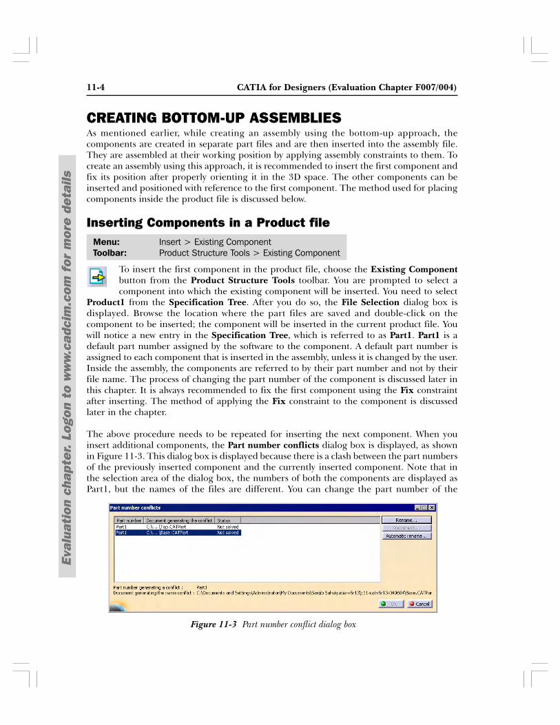
The above procedure needs to be repeated for inserting the next component. When youinsert additional components, the Part number conflicts dialog box is displayed, as shownin Figure 11-3. This dialog box is displayed because there is a clash between the part numbersof the previously inserted component and the currently inserted component. Note that inthe selection area of the dialog box, the numbers of both the components are displayed asPart1, but the names of the files are different. You can change the part number of the
Figure 11-3 Part number conflict dialog box
Assembly Modeling 11-5
Eval
uati
on c
hapt
er.
Logo
n to
ww
w.c
adci
m.c
om f
or m
ore
deta
ils
component using the options available in this dialog box. There are two active buttons availableon the right of the selection area of this dialog box: Rename and Automatic Rename.
If you select the component to be renamed and choose the Automatic rename button, thepart number of the selected component is renamed from Part1 to Part1.1. Choose the OKbutton from the Part number conflicts dialog box to insert the second component into theProduct file. Follow the same procedure to rename the part number, while inserting othercomponents. Note that while inserting the third component, the first time when you renamethe component using the Automatic Rename option the part number is changed to Part1.1.Because this part number is already assigned to the second component, the Part numberconflicts dialog box is again displayed after choosing the OK button and shows the conflictbetween the second and third component. You need to choose the Automatic rename buttonagain to change the part number of the third component. Now, the third component will berenamed from Part1.1 to Part1.1.2. Choosing the OK button will insert the third componentinto the product file. This means if you are inserting the nth component, the automatic renamebutton has to be used n-1 times. This way the part number of every new component keeps onchanging in a similar fashion, and the same is represented in the Specification Tree, asshown in Figure 11-4.
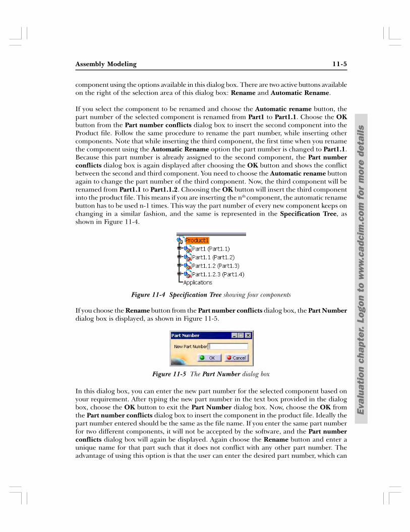
If you choose the Rename button from the Part number conflicts dialog box, the Part Numberdialog box is displayed, as shown in Figure 11-5.
In this dialog box, you can enter the new part number for the selected component based onyour requirement. After typing the new part number in the text box provided in the dialogbox, choose the OK button to exit the Part Number dialog box. Now, choose the OK fromthe Part number conflicts dialog box to insert the component in the product file. Ideally thepart number entered should be the same as the file name. If you enter the same part numberfor two different components, it will not be accepted by the software, and the Part numberconflicts dialog box will again be displayed. Again choose the Rename button and enter aunique name for that part such that it does not conflict with any other part number. Theadvantage of using this option is that the user can enter the desired part number, which can
Figure 11-4 Specification Tree showing four components
Figure 11-5 The Part Number dialog box
11-6 CATIA for Designers (Evaluation Chapter F007/004)
Eval
uati
on c
hapt
er.
Logo
n to
ww
w.c
adci
m.c
om f
or m
ore
deta
ils
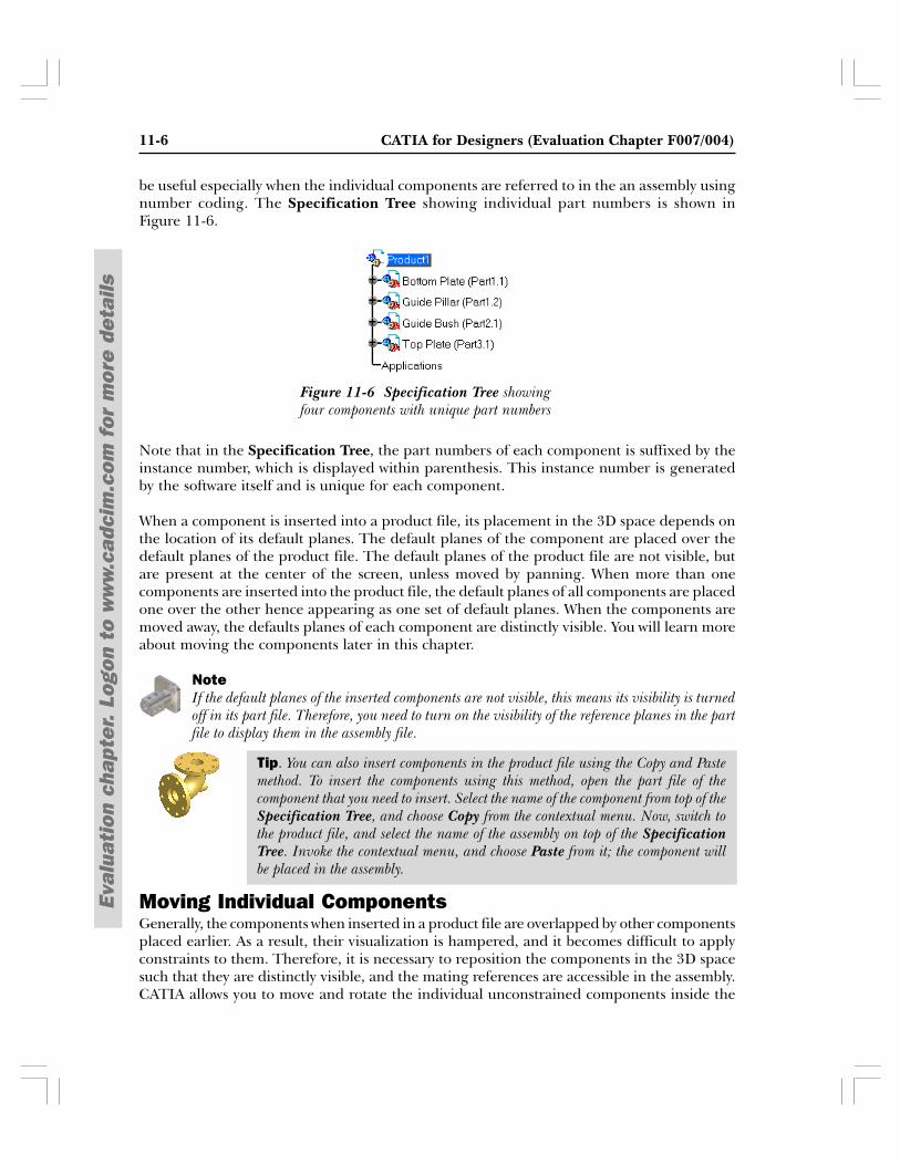
Figure 11-6 Specification Tree showingfour components with unique part numbers
be useful especially when the individual components are referred to in the an assembly usingnumber coding. The Specification Tree showing individual part numbers is shown inFigure 11-6.
Note that in the Specification Tree, the part numbers of each component is suffixed by theinstance number, which is displayed within parenthesis. This instance number is generatedby the software itself and is unique for each component.
When a component is inserted into a product file, its placement in the 3D space depends onthe location of its default planes. The default planes of the component are placed over thedefault planes of the product file. The default planes of the product file are not visible, butare present at the center of the screen, unless moved by panning. When more than onecomponents are inserted into the product file, the default planes of all components are placedone over the other hence appearing as one set of default planes. When the components aremoved away, the defaults planes of each component are distinctly visible. You will learn moreabout moving the components later in this chapter.
NoteIf the default planes of the inserted components are not visible, this means its visibility is turnedoff in its part file. Therefore, you need to turn on the visibility of the reference planes in the partfile to display them in the assembly file.
Moving Individual ComponentsGenerally, the components when inserted in a product file are overlapped by other componentsplaced earlier. As a result, their visualization is hampered, and it becomes difficult to applyconstraints to them. Therefore, it is necessary to reposition the components in the 3D spacesuch that they are distinctly visible, and the mating references are accessible in the assembly.CATIA allows you to move and rotate the individual unconstrained components inside the
Tip. You can also insert components in the product file using the Copy and Pastemethod. To insert the components using this method, open the part file of thecomponent that you need to insert. Select the name of the component from top of theSpecification Tree, and choose Copy from the contextual menu. Now, switch tothe product file, and select the name of the assembly on top of the SpecificationTree. Invoke the contextual menu, and choose Paste from it; the component willbe placed in the assembly.
Assembly Modeling 11-7
Eval
uati
on c
hapt
er.
Logo
n to
ww
w.c
adci
m.c
om f
or m
ore
deta
ils
product file without affecting the position and location of the other components. Thereorientation of the component can be carried out using three different methods, which arediscussed in the following sections.
Moving and Rotating Using the Manipulation Tool
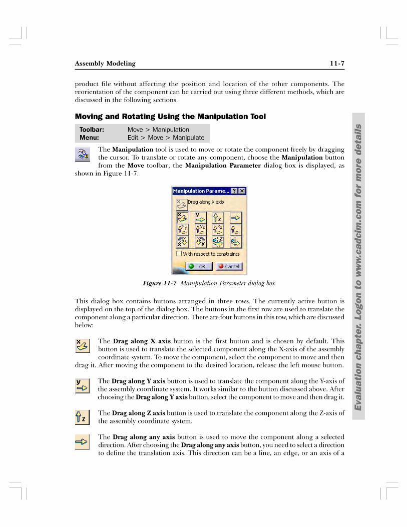
The Manipulation tool is used to move or rotate the component freely by draggingthe cursor. To translate or rotate any component, choose the Manipulation buttonfrom the Move toolbar; the Manipulation Parameter dialog box is displayed, as
shown in Figure 11-7.
This dialog box contains buttons arranged in three rows. The currently active button isdisplayed on the top of the dialog box. The buttons in the first row are used to translate thecomponent along a particular direction. There are four buttons in this row, which are discussedbelow:
The Drag along X axis button is the first button and is chosen by default. Thisbutton is used to translate the selected component along the X-axis of the assemblycoordinate system. To move the component, select the component to move and then
drag it. After moving the component to the desired location, release the left mouse button.
The Drag along Y axis button is used to translate the component along the Y-axis ofthe assembly coordinate system. It works similar to the button discussed above. Afterchoosing the Drag along Y axis button, select the component to move and then drag it.
The Drag along Z axis button is used to translate the component along the Z-axis ofthe assembly coordinate system.
The Drag along any axis button is used to move the component along a selecteddirection. After choosing the Drag along any axis button, you need to select a directionto define the translation axis. This direction can be a line, an edge, or an axis of a
Toolbar: Move > ManipulationMenu: Edit > Move > Manipulate
Figure 11-7 Manipulation Parameter dialog box
11-8 CATIA for Designers (Evaluation Chapter F007/004)
Eval
uati
on c
hapt
er.
Logo
n to
ww
w.c
adci
m.c
om f
or m
ore
deta
ils
cylindrical feature. After selecting the axis of translation, drag the selected component alongthe selected direction.
The buttons in the second row of the Manipulation Parameter dialog box are used to movethe selected component along a particular plane. These planar translation buttons arediscussed below.
The Drag along XY plane button is used to translate the selected component parallelto the XY plane of the assembly coordinate system.
The Drag along YZ plane button is used to translate the selected component parallelto the YZ plane of the assembly coordinate system.
Drag along XZ plane button is used to translate the selected component parallel tothe XZ plane of the assembly coordinate system.
Drag along any plane button is used to move the selected component parallel to aspecified plane. After choosing the Drag along any plane button, you need to selecta plane for planar translation. This plane can be a construction plane, a planar face,
or a surface. After selecting the plane for translation, select the component to move and thendrag it on the selected plane.
The buttons on the third row of the Manipulation Parameter dialog box are used to rotate theselected component around an axis. These rotation buttons are discussed below.
The Drag around X axis button is used to rotate the selected component around theX-axis of the assembly coordinate system.
The Drag around Y axis button is used to rotate the selected component around theY-axis of the assembly coordinate system.
The Drag around Z axis button is used to rotate the selected component around theZ-axis of the assembly coordinate system.
The Drag around any axis button is used to rotate the selected component around aspecified axis. After choosing the Drag around any axis button, you need to select aline to define the rotation axis. This line can be an edge of the component or an axis
of a cylindrical feature. After selecting the axis for rotation, select the component to rotateand then drag it.
The With respect to constraints check box is selected to move or rotate the componentswithin its available degrees of freedom after applying constraints. You will learn more aboutapplying constraints later in this chapter.
Assembly Modeling 11-9
Eval
uati
on c
hapt
er.
Logo
n to
ww
w.c
adci
m.c
om f
or m
ore
deta
ils
Moving Components Using the Snap Tool
The Snap tool is used to move the component by snapping the geometric element offirst component on the other component or on the same component. The movementof the component depends on the selection of the geometric elements. The element
selected first will move to snap the second element. For example, if you first select a line andthen a point, the line will be reoriented in such a way that it passes through the selectedpoint.
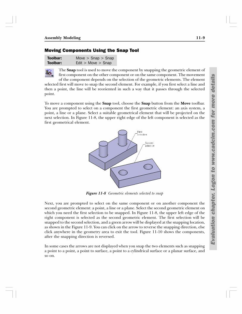
To move a component using the Snap tool, choose the Snap button from the Move toolbar.You are prompted to select on a component the first geometric element: an axis system, apoint, a line or a plane. Select a suitable geometrical element that will be projected on thenext selection. In Figure 11-8, the upper right edge of the left component is selected as thefirst geometrical element.
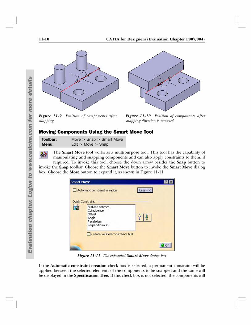
Next, you are prompted to select on the same component or on another component thesecond geometric element: a point, a line or a plane. Select the second geometric element onwhich you need the first selection to be snapped. In Figure 11-8, the upper left edge of theright component is selected as the second geometric element. The first selection will besnapped to the second selection, and a green arrow will be displayed at the snapping location,as shown in the Figure 11-9. You can click on the arrow to reverse the snapping direction, elseclick anywhere in the geometry area to exit the tool. Figure 11-10 shows the components,after the snapping direction is reversed.
In some cases the arrows are not displayed when you snap the two elements such as snappinga point to a point, a point to surface, a point to a cylindrical surface or a planar surface, andso on.
Toolbar: Move > Snap > SnapToolbar: Edit > Move > Snap
Figure 11-8 Geometric elements selected to snap
11-10 CATIA for Designers (Evaluation Chapter F007/004)
Eval
uati
on c
hapt
er.
Logo
n to
ww
w.c
adci
m.c
om f
or m
ore
deta
ils
Moving Components Using the Smart Move Tool
The Smart Move tool works as a multipurpose tool. This tool has the capability ofmanipulating and snapping components and can also apply constraints to them, ifrequired. To invoke this tool, choose the down arrow besides the Snap button to
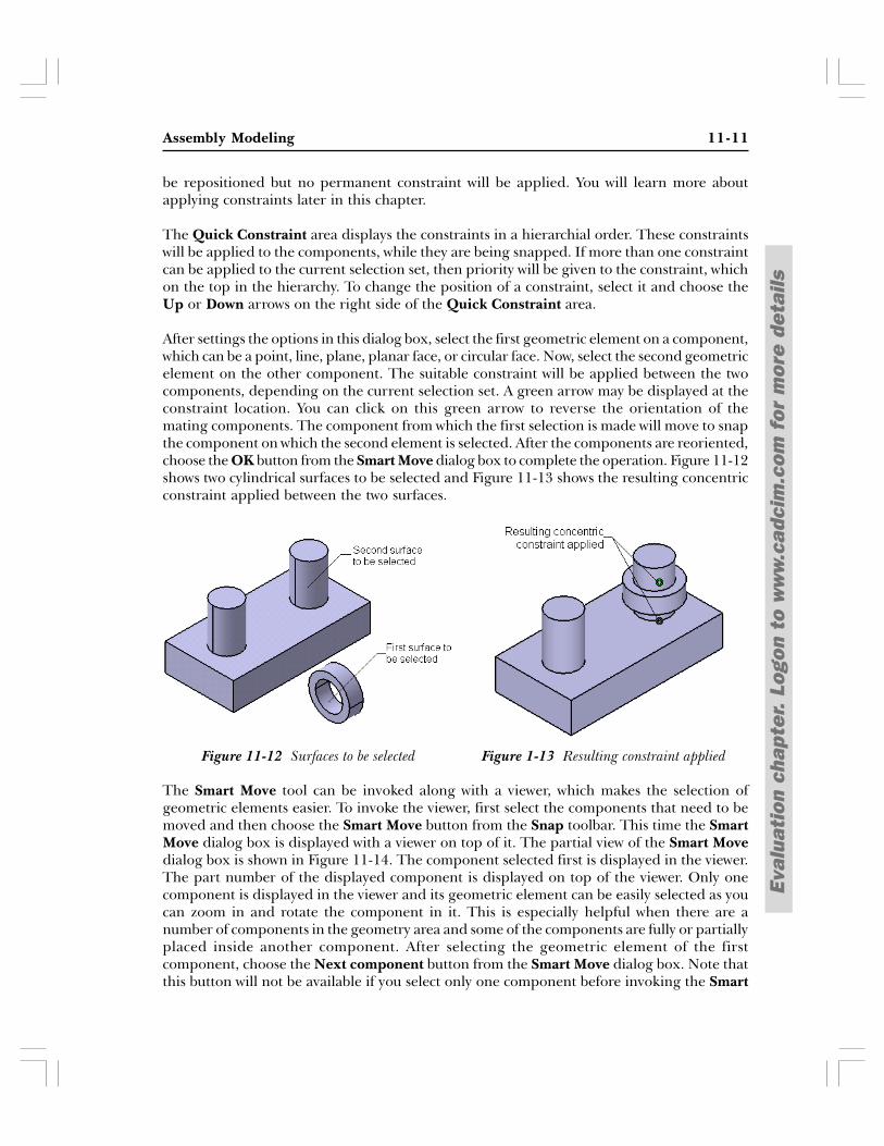
invoke the Snap toolbar. Choose the Smart Move button to invoke the Smart Move dialogbox. Choose the More button to expand it, as shown in Figure 11-11.
If the Automatic constraint creation check box is selected, a permanent constraint will beapplied between the selected elements of the components to be snapped and the same willbe displayed in the Specification Tree. If this check box is not selected, the components will
Figure 11-10 Position of components aftersnapping direction is reversed
Figure 11-9 Position of components aftersnapping
Toolbar: Move > Snap > Smart MoveMenu: Edit > Move > Snap
Figure 11-11 The expanded Smart Move dialog box
Assembly Modeling 11-11
Eval
uati
on c
hapt
er.
Logo
n to
ww
w.c
adci
m.c
om f
or m
ore
deta
ils
be repositioned but no permanent constraint will be applied. You will learn more aboutapplying constraints later in this chapter.
The Quick Constraint area displays the constraints in a hierarchial order. These constraintswill be applied to the components, while they are being snapped. If more than one constraintcan be applied to the current selection set, then priority will be given to the constraint, whichon the top in the hierarchy. To change the position of a constraint, select it and choose theUp or Down arrows on the right side of the Quick Constraint area.
After settings the options in this dialog box, select the first geometric element on a component,which can be a point, line, plane, planar face, or circular face. Now, select the second geometricelement on the other component. The suitable constraint will be applied between the twocomponents, depending on the current selection set. A green arrow may be displayed at theconstraint location. You can click on this green arrow to reverse the orientation of themating components. The component from which the first selection is made will move to snapthe component on which the second element is selected. After the components are reoriented,choose the OK button from the Smart Move dialog box to complete the operation. Figure 11-12shows two cylindrical surfaces to be selected and Figure 11-13 shows the resulting concentricconstraint applied between the two surfaces.
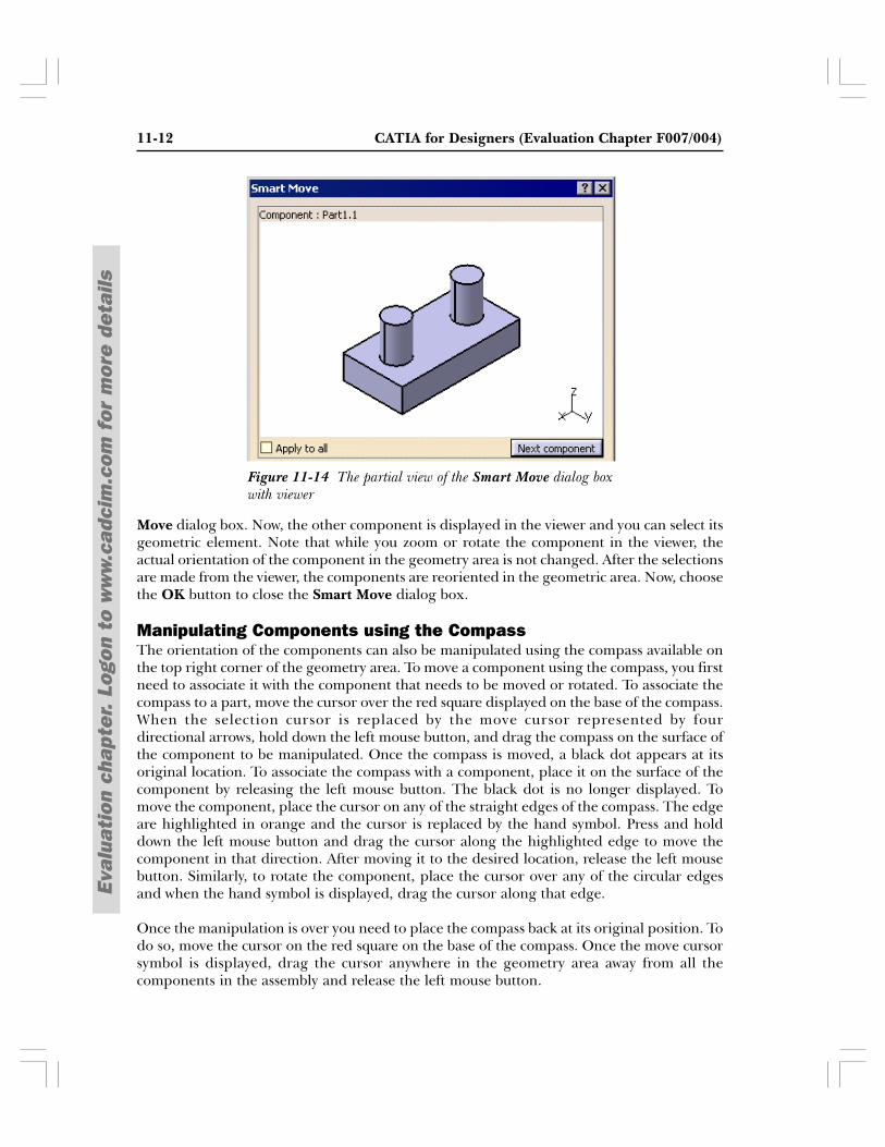
The Smart Move tool can be invoked along with a viewer, which makes the selection ofgeometric elements easier. To invoke the viewer, first select the components that need to bemoved and then choose the Smart Move button from the Snap toolbar. This time the SmartMove dialog box is displayed with a viewer on top of it. The partial view of the Smart Movedialog box is shown in Figure 11-14. The component selected first is displayed in the viewer.The part number of the displayed component is displayed on top of the viewer. Only onecomponent is displayed in the viewer and its geometric element can be easily selected as youcan zoom in and rotate the component in it. This is especially helpful when there are anumber of components in the geometry area and some of the components are fully or partiallyplaced inside another component. After selecting the geometric element of the firstcomponent, choose the Next component button from the Smart Move dialog box. Note thatthis button will not be available if you select only one component before invoking the Smart
Figure 1-13 Resulting constraint appliedFigure 11-12 Surfaces to be selected
11-12 CATIA for Designers (Evaluation Chapter F007/004)
Eval
uati
on c
hapt
er.
Logo
n to
ww
w.c
adci
m.c
om f
or m
ore
deta
ils
Move dialog box. Now, the other component is displayed in the viewer and you can select itsgeometric element. Note that while you zoom or rotate the component in the viewer, theactual orientation of the component in the geometry area is not changed. After the selectionsare made from the viewer, the components are reoriented in the geometric area. Now, choosethe OK button to close the Smart Move dialog box.
Manipulating Components using the CompassThe orientation of the components can also be manipulated using the compass available onthe top right corner of the geometry area. To move a component using the compass, you firstneed to associate it with the component that needs to be moved or rotated. To associate thecompass to a part, move the cursor over the red square displayed on the base of the compass.When the selection cursor is replaced by the move cursor represented by fourdirectional arrows, hold down the left mouse button, and drag the compass on the surface ofthe component to be manipulated. Once the compass is moved, a black dot appears at itsoriginal location. To associate the compass with a component, place it on the surface of thecomponent by releasing the left mouse button. The black dot is no longer displayed. Tomove the component, place the cursor on any of the straight edges of the compass. The edgeare highlighted in orange and the cursor is replaced by the hand symbol. Press and holddown the left mouse button and drag the cursor along the highlighted edge to move thecomponent in that direction. After moving it to the desired location, release the left mousebutton. Similarly, to rotate the component, place the cursor over any of the circular edgesand when the hand symbol is displayed, drag the cursor along that edge.
Once the manipulation is over you need to place the compass back at its original position. Todo so, move the cursor on the red square on the base of the compass. Once the move cursorsymbol is displayed, drag the cursor anywhere in the geometry area away from all thecomponents in the assembly and release the left mouse button.
Figure 11-14 The partial view of the Smart Move dialog boxwith viewer
Assembly Modeling 11-13
Eval
uati
on c
hapt
er.
Logo
n to
ww
w.c
adci
m.c
om f
or m
ore
deta
ils
NoteWhen the compass is placed back in its original location, the orientation of the compass remainsthe same as it was after manipulating the component. This may lead to confusion. To bring thecompass back to its default orientation, place the compass over a perfectly horizontal surface.Then place the compass back at its default location.
Applying ConstraintsAfter placing the components in the product file, you need to assemble them. By assemblingthe components, you will constrain the degree of freedom of the components. As mentionedearlier, the components are assembled using the constraints. Constraints help you to preciselyplace and position the components with respect to the other components and the surroundingsin the assembly. If all degrees of freedom of all components of the assembly are restricted, itis called a fully constrained assembly. Else it is called a partially constrained assembly. Ifsome mechanism needs to be created after assembling the components, some degrees offreedom of the assembly needs to be kept free intentionally, so that movements can be achievedin that direction. Various types of constraints available in CATIA are discussed below.
Fix Component Constraint
The Fix Component constraint is used to fix the location of the selected componentin the 3D space. Once the orientation of the component is fixed, its orientationcannot be changed. To invoke this tool, choose the Fix Component button from the
Constraints toolbar; you are prompted to select the component to be fixed. You can selectthe component from the geometry area or from the Specification Tree. Once the componentis selected, an anchor symbol is displayed on the component. Now, other components canbe constrained with respect to the fixed component. While doing so, the orientation of thebase component will not be altered and the other components will be reoriented to apply theconstraints. It is always advisable to fix the base component at its default location so that itcan be used as a reference for other components. The Fix Component constraint is displayedin the Specification Tree. To view the applied constraints, expand the Constraints optionfrom the Specification Tree.
Coincidence Constraint
The Coincidence Constraint is applied to coincide the central axis of the cylindricalfeatures that are selected from two different components. This option can also beused to apply Coincident constraint between edges, points, planes or planar faces.
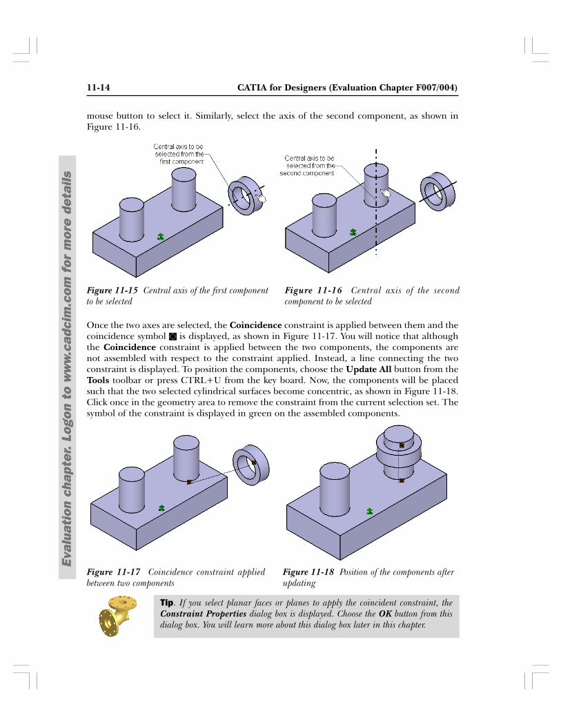
To invoke this tool, choose the Coincidence Constraint button from the Constraints toolbar;the Assistant dialog box is displayed that provides information about the selected constraint.You can select the Do not prompt in the future check box, if you do not want to display thisdialog box again. Now, move the cursor over a cylindrical surface to display the central axis.When the preview of the central axis is displayed, as shown in Figure 11-15, click the left
Menu: Insert > CoincidenceToolbar: Constraints > Coincidence Constraint
Menu: Insert > FixToolbar: Constraints > Fix Component
11-14 CATIA for Designers (Evaluation Chapter F007/004)
Eval
uati
on c
hapt
er.
Logo
n to
ww
w.c
adci
m.c
om f
or m
ore
deta
ils
mouse button to select it. Similarly, select the axis of the second component, as shown inFigure 11-16.
Once the two axes are selected, the Coincidence constraint is applied between them and thecoincidence symbol is displayed, as shown in Figure 11-17. You will notice that althoughthe Coincidence constraint is applied between the two components, the components arenot assembled with respect to the constraint applied. Instead, a line connecting the twoconstraint is displayed. To position the components, choose the Update All button from theTools toolbar or press CTRL+U from the key board. Now, the components will be placedsuch that the two selected cylindrical surfaces become concentric, as shown in Figure 11-18.Click once in the geometry area to remove the constraint from the current selection set. Thesymbol of the constraint is displayed in green on the assembled components.
Figure 11-16 Central axis of the secondcomponent to be selected
Figure 11-15 Central axis of the first componentto be selected
Figure 11-18 Position of the components afterupdating
Figure 11-17 Coincidence constraint appliedbetween two components
Tip. If you select planar faces or planes to apply the coincident constraint, theConstraint Properties dialog box is displayed. Choose the OK button from thisdialog box. You will learn more about this dialog box later in this chapter.
Assembly Modeling 11-15
Eval
uati
on c
hapt
er.
Logo
n to
ww
w.c
adci
m.c
om f
or m
ore
deta
ils
Contact Constraint
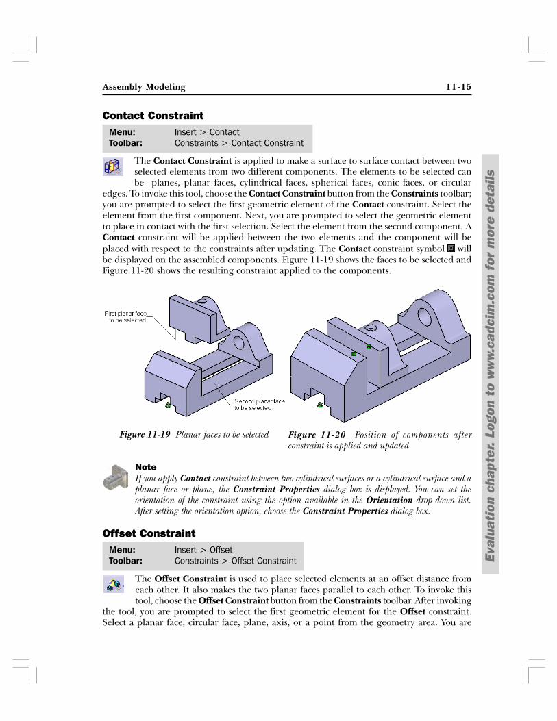
The Contact Constraint is applied to make a surface to surface contact between twoselected elements from two different components. The elements to be selected canbe planes, planar faces, cylindrical faces, spherical faces, conic faces, or circular
edges. To invoke this tool, choose the Contact Constraint button from the Constraints toolbar;you are prompted to select the first geometric element of the Contact constraint. Select theelement from the first component. Next, you are prompted to select the geometric elementto place in contact with the first selection. Select the element from the second component. AContact constraint will be applied between the two elements and the component will beplaced with respect to the constraints after updating. The Contact constraint symbol willbe displayed on the assembled components. Figure 11-19 shows the faces to be selected andFigure 11-20 shows the resulting constraint applied to the components.
NoteIf you apply Contact constraint between two cylindrical surfaces or a cylindrical surface and aplanar face or plane, the Constraint Properties dialog box is displayed. You can set theorientation of the constraint using the option available in the Orientation drop-down list.After setting the orientation option, choose the Constraint Properties dialog box.
Offset Constraint
The Offset Constraint is used to place selected elements at an offset distance fromeach other. It also makes the two planar faces parallel to each other. To invoke thistool, choose the Offset Constraint button from the Constraints toolbar. After invoking
the tool, you are prompted to select the first geometric element for the Offset constraint.Select a planar face, circular face, plane, axis, or a point from the geometry area. You are
Menu: Insert > ContactToolbar: Constraints > Contact Constraint
Figure 11-20 Position of components afterconstraint is applied and updated
Figure 11-19 Planar faces to be selected
Menu: Insert > OffsetToolbar: Constraints > Offset Constraint
11-16 CATIA for Designers (Evaluation Chapter F007/004)
Eval
uati
on c
hapt
er.
Logo
n to
ww
w.c
adci
m.c
om f
or m
ore
deta
ils
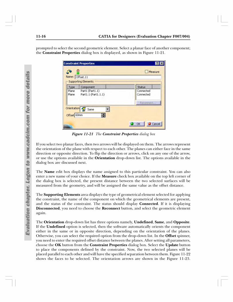
prompted to select the second geometric element. Select a planar face of another component;the Constraint Properties dialog box is displayed, as shown in Figure 11-21.
If you select two planar faces, then two arrows will be displayed on them. The arrows representthe orientation of the plane with respect to each other. The planes can either face in the samedirection or opposite direction. To flip the direction or arrows, click on any one of the arrow,or use the options available in the Orientation drop-down list. The options available in thedialog box are discussed next.
The Name edit box displays the name assigned to this particular constraint. You can alsoenter a new name of your choice. If the Measure check box available on the top left corner ofthe dialog box is selected, the present distance between the two selected surfaces will bemeasured from the geometry, and will be assigned the same value as the offset distance.
The Supporting Elements area displays the type of geometrical element selected for applyingthe constraint, the name of the component on which the geometrical elements are present,and the status of the constraint. The status should display Connected. If it is displayingDisconnected, you need to choose the Reconnect button, and select the geometric elementagain.
The Orientation drop-down list has three options namely, Undefined, Same, and Opposite.If the Undefined option is selected, then the software automatically orients the componenteither in the same or in opposite direction, depending on the orientation of the planes.Otherwise, you can select the required option from the drop-down list. In the Offset spinner,you need to enter the required offset distance between the planes. After setting all parameters,choose the OK button from the Constraint Properties dialog box. Select the Update buttonto place the components defined by the constraint. Now, the two selected planes will beplaced parallel to each other and will have the specified separation between them. Figure 11-22shows the faces to be selected. The orientation arrows are shown in the Figure 11-23.
Figure 11-21 The Constraint Properties dialog box
Assembly Modeling 11-17
Eval
uati
on c
hapt
er.
Logo
n to
ww
w.c
adci
m.c
om f
or m
ore
deta
ils
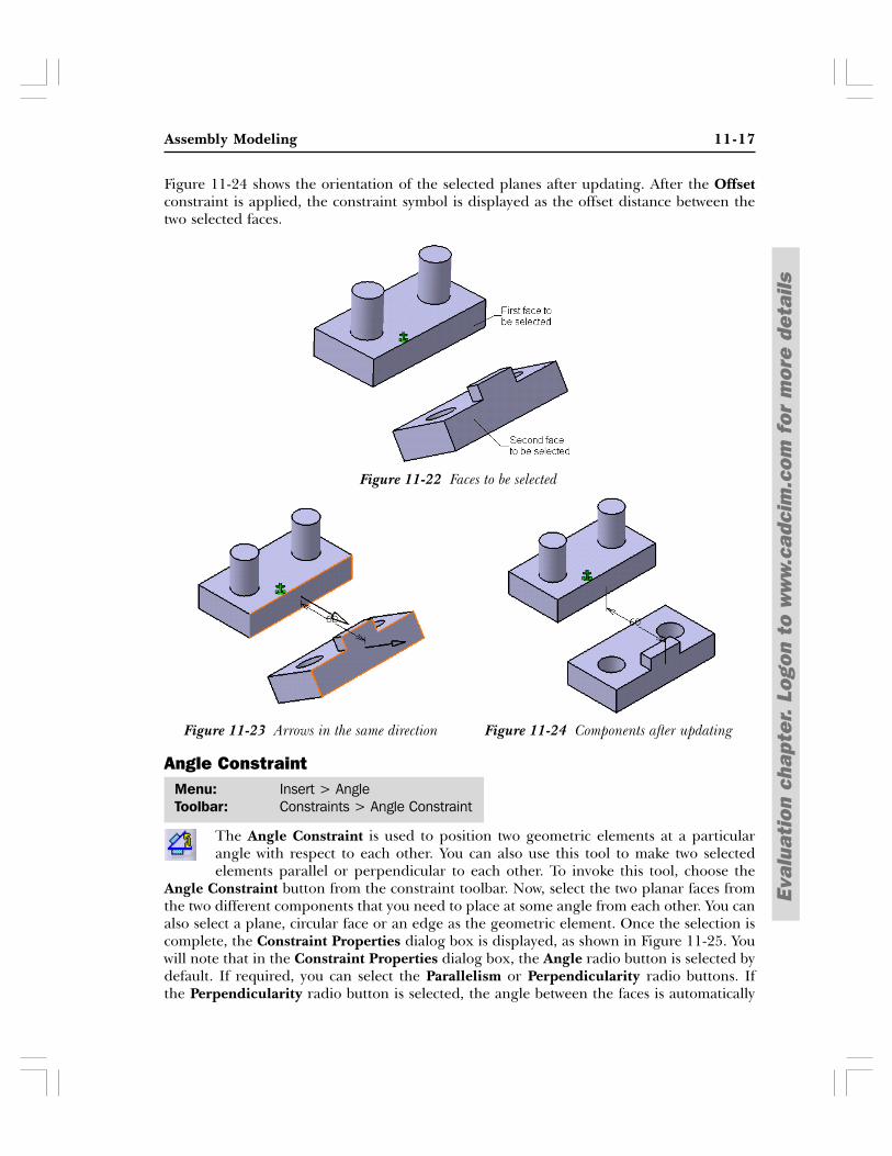
Figure 11-24 shows the orientation of the selected planes after updating. After the Offsetconstraint is applied, the constraint symbol is displayed as the offset distance between thetwo selected faces.
Angle Constraint
The Angle Constraint is used to position two geometric elements at a particularangle with respect to each other. You can also use this tool to make two selectedelements parallel or perpendicular to each other. To invoke this tool, choose the
Angle Constraint button from the constraint toolbar. Now, select the two planar faces fromthe two different components that you need to place at some angle from each other. You canalso select a plane, circular face or an edge as the geometric element. Once the selection iscomplete, the Constraint Properties dialog box is displayed, as shown in Figure 11-25. Youwill note that in the Constraint Properties dialog box, the Angle radio button is selected bydefault. If required, you can select the Parallelism or Perpendicularity radio buttons. Ifthe Perpendicularity radio button is selected, the angle between the faces is automatically
Menu: Insert > AngleToolbar: Constraints > Angle Constraint
Figure 11-24 Components after updatingFigure 11-23 Arrows in the same direction
Figure 11-22 Faces to be selected
11-18 CATIA for Designers (Evaluation Chapter F007/004)
Eval
uati
on c
hapt
er.
Logo
n to
ww
w.c
adci
m.c
om f
or m
ore
deta
ils
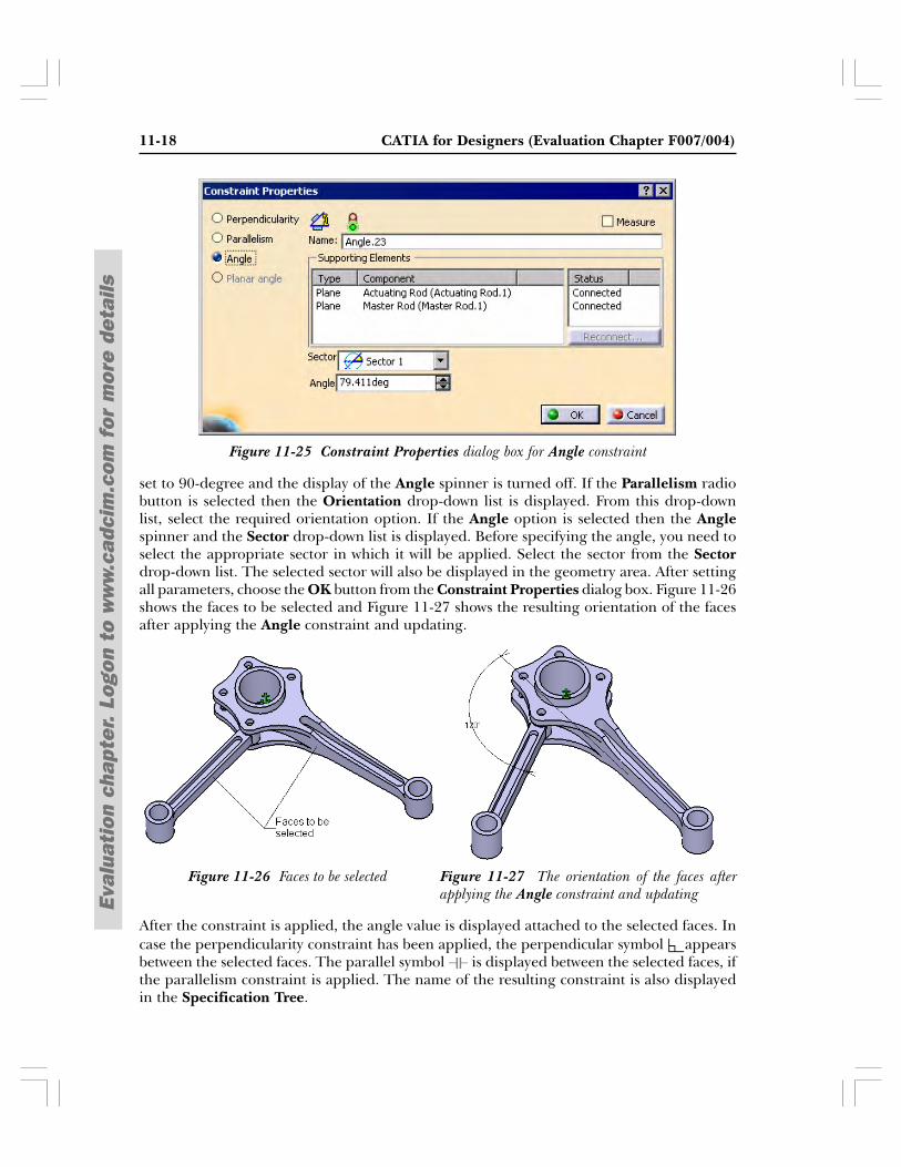
Figure 11-25 Constraint Properties dialog box for Angle constraint
set to 90-degree and the display of the Angle spinner is turned off. If the Parallelism radiobutton is selected then the Orientation drop-down list is displayed. From this drop-downlist, select the required orientation option. If the Angle option is selected then the Anglespinner and the Sector drop-down list is displayed. Before specifying the angle, you need toselect the appropriate sector in which it will be applied. Select the sector from the Sectordrop-down list. The selected sector will also be displayed in the geometry area. After settingall parameters, choose the OK button from the Constraint Properties dialog box. Figure 11-26shows the faces to be selected and Figure 11-27 shows the resulting orientation of the facesafter applying the Angle constraint and updating.
After the constraint is applied, the angle value is displayed attached to the selected faces. Incase the perpendicularity constraint has been applied, the perpendicular symbol appearsbetween the selected faces. The parallel symbol is displayed between the selected faces, ifthe parallelism constraint is applied. The name of the resulting constraint is also displayedin the Specification Tree.
Figure 11-27 The orientation of the faces afterapplying the Angle constraint and updating
Figure 11-26 Faces to be selected
Assembly Modeling 11-19
Eval
uati
on c
hapt
er.
Logo
n to
ww
w.c
adci
m.c
om f
or m
ore
deta
ils
Fix Together
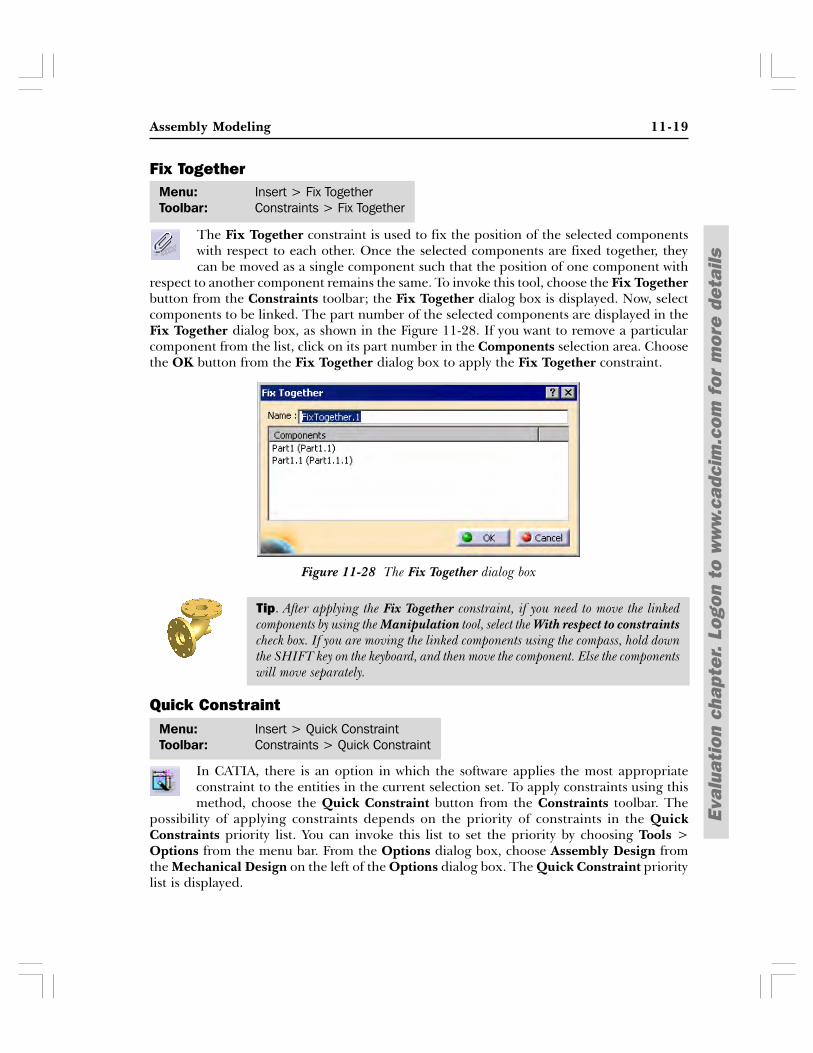
The Fix Together constraint is used to fix the position of the selected componentswith respect to each other. Once the selected components are fixed together, theycan be moved as a single component such that the position of one component with
respect to another component remains the same. To invoke this tool, choose the Fix Togetherbutton from the Constraints toolbar; the Fix Together dialog box is displayed. Now, selectcomponents to be linked. The part number of the selected components are displayed in theFix Together dialog box, as shown in the Figure 11-28. If you want to remove a particularcomponent from the list, click on its part number in the Components selection area. Choosethe OK button from the Fix Together dialog box to apply the Fix Together constraint.
Quick Constraint
In CATIA, there is an option in which the software applies the most appropriateconstraint to the entities in the current selection set. To apply constraints using thismethod, choose the Quick Constraint button from the Constraints toolbar. The
possibility of applying constraints depends on the priority of constraints in the QuickConstraints priority list. You can invoke this list to set the priority by choosing Tools >Options from the menu bar. From the Options dialog box, choose Assembly Design fromthe Mechanical Design on the left of the Options dialog box. The Quick Constraint prioritylist is displayed.
Menu: Insert > Fix TogetherToolbar: Constraints > Fix Together
Tip. After applying the Fix Together constraint, if you need to move the linkedcomponents by using the Manipulation tool, select the With respect to constraintscheck box. If you are moving the linked components using the compass, hold downthe SHIFT key on the keyboard, and then move the component. Else the componentswill move separately.
Figure 11-28 The Fix Together dialog box
Menu: Insert > Quick ConstraintToolbar: Constraints > Quick Constraint
11-20 CATIA for Designers (Evaluation Chapter F007/004)
Eval
uati
on c
hapt
er.
Logo
n to
ww
w.c
adci
m.c
om f
or m
ore
deta
ils
Now, select the two geometric elements to be constrained. The software will automaticallyapply the most appropriate constraint between the selected geometric elements. This savestime in assembling components. However, you need to be careful while selecting the geometricelements because the orientation of the components depends on it.
Reuse Pattern
Sometimes, while assembling the components, you may need to assemble more thanone instance of the component in a specified arrangement. Consider a case of aflange coupling where you need to assemble eight instances of nuts and bolts to
fasten the coupling. This is very tedious and time-consuming process. Therefore, to reducethe time in the assembly design cycle, CATIA provides you with the Resume Pattern tool toinsert and constrain multiple copies of a component over an existing pattern. The patterncan be rectangular, circular, or a user pattern.
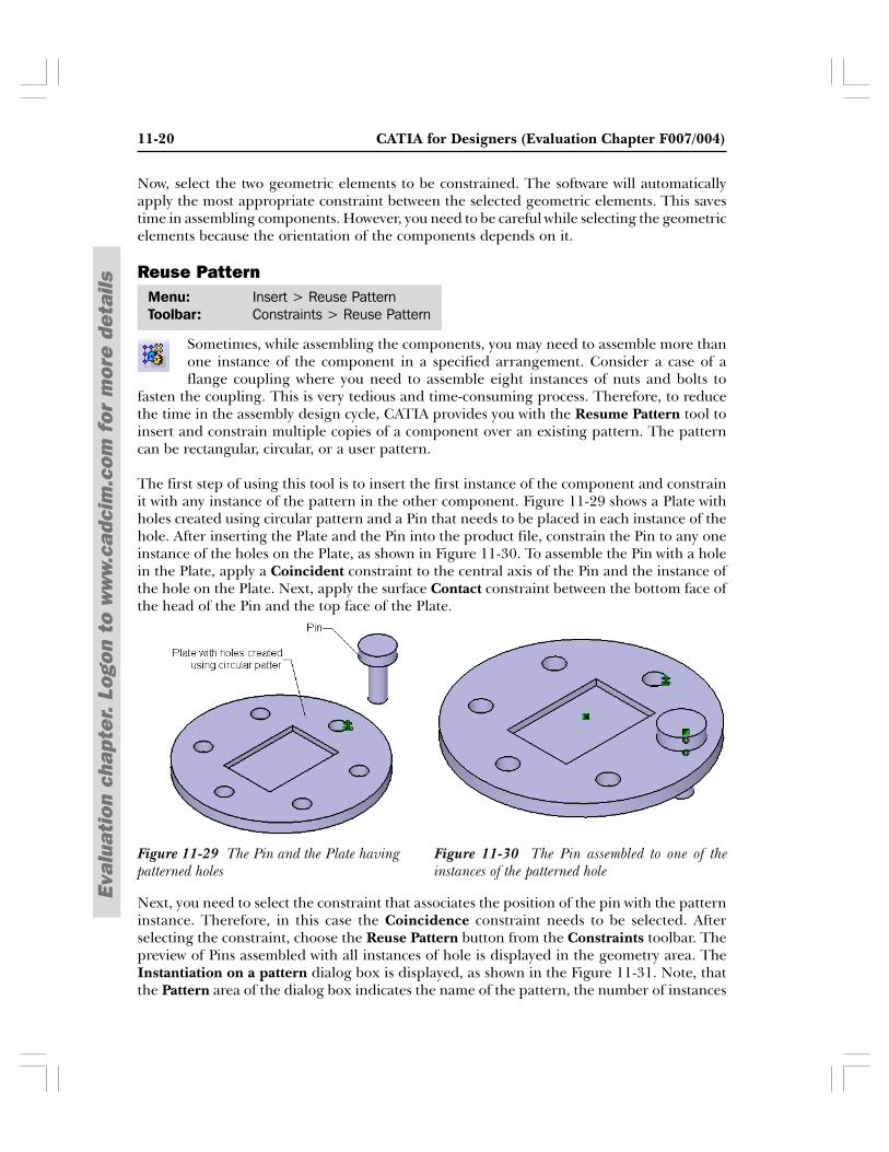
The first step of using this tool is to insert the first instance of the component and constrainit with any instance of the pattern in the other component. Figure 11-29 shows a Plate withholes created using circular pattern and a Pin that needs to be placed in each instance of thehole. After inserting the Plate and the Pin into the product file, constrain the Pin to any oneinstance of the holes on the Plate, as shown in Figure 11-30. To assemble the Pin with a holein the Plate, apply a Coincident constraint to the central axis of the Pin and the instance ofthe hole on the Plate. Next, apply the surface Contact constraint between the bottom face ofthe head of the Pin and the top face of the Plate.
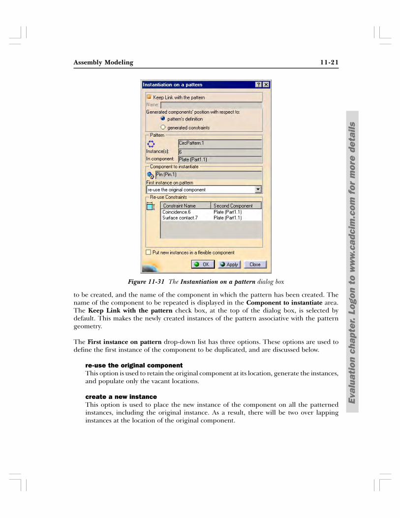
Next, you need to select the constraint that associates the position of the pin with the patterninstance. Therefore, in this case the Coincidence constraint needs to be selected. Afterselecting the constraint, choose the Reuse Pattern button from the Constraints toolbar. Thepreview of Pins assembled with all instances of hole is displayed in the geometry area. TheInstantiation on a pattern dialog box is displayed, as shown in the Figure 11-31. Note, thatthe Pattern area of the dialog box indicates the name of the pattern, the number of instances
Menu: Insert > Reuse PatternToolbar: Constraints > Reuse Pattern
Figure 11-30 The Pin assembled to one of theinstances of the patterned hole
Figure 11-29 The Pin and the Plate havingpatterned holes
Assembly Modeling 11-21
Eval
uati
on c
hapt
er.
Logo
n to
ww
w.c
adci
m.c
om f
or m
ore
deta
ils
to be created, and the name of the component in which the pattern has been created. Thename of the component to be repeated is displayed in the Component to instantiate area.The Keep Link with the pattern check box, at the top of the dialog box, is selected bydefault. This makes the newly created instances of the pattern associative with the patterngeometry.
The First instance on pattern drop-down list has three options. These options are used todefine the first instance of the component to be duplicated, and are discussed below.
re-use the original componentThis option is used to retain the original component at its location, generate the instances,and populate only the vacant locations.
create a new instanceThis option is used to place the new instance of the component on all the patternedinstances, including the original instance. As a result, there will be two over lappinginstances at the location of the original component.
Figure 11-31 The Instantiation on a pattern dialog box
11-22 CATIA for Designers (Evaluation Chapter F007/004)
Eval
uati
on c
hapt
er.
Logo
n to
ww
w.c
adci
m.c
om f
or m
ore
deta
ils
cut and paste the original componentThis option is used to remove the original component from its location and place thenew instance of the component at all locations.
By default, the pattern’s definition radio button is selected in the Generated component’sposition with respect to area of the Instantiation on a pattern dialog box. This optionfacilitates in placing and constraining all instances based on the selected reference pattern. Ifyou select the generated constraints radio button, the constraints applied to the parentinstance are also applied individually to all pattern instances.
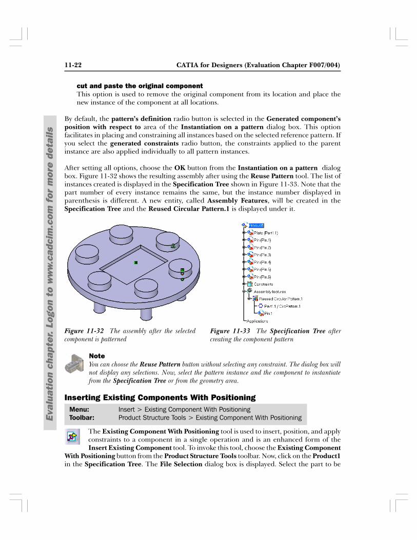
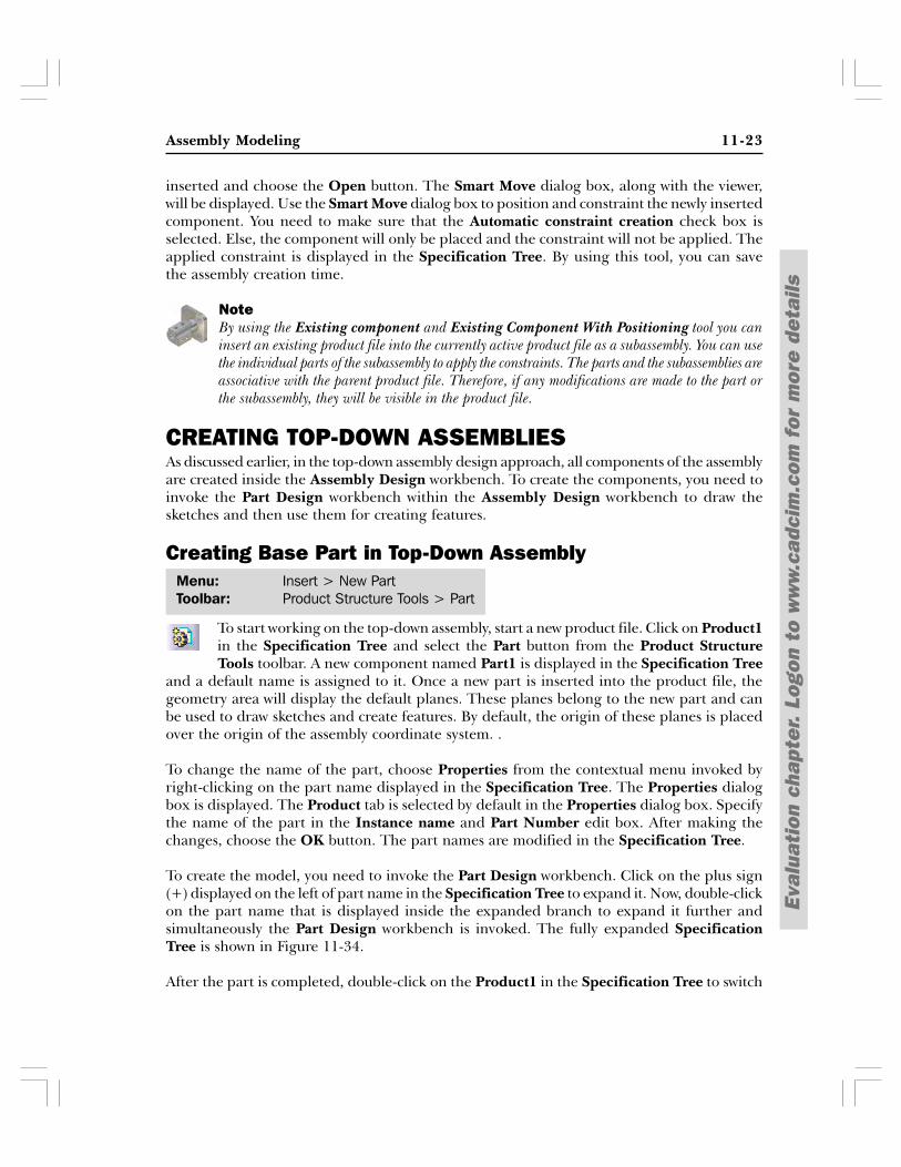
After setting all options, choose the OK button from the Instantiation on a pattern dialogbox. Figure 11-32 shows the resulting assembly after using the Reuse Pattern tool. The list ofinstances created is displayed in the Specification Tree shown in Figure 11-33. Note that thepart number of every instance remains the same, but the instance number displayed inparenthesis is different. A new entity, called Assembly Features, will be created in theSpecification Tree and the Reused Circular Pattern.1 is displayed under it.
NoteYou can choose the Reuse Pattern button without selecting any constraint. The dialog box willnot display any selections. Now, select the pattern instance and the component to instantiatefrom the Specification Tree or from the geometry area.
Inserting Existing Components With Positioning
The Existing Component With Positioning tool is used to insert, position, and applyconstraints to a component in a single operation and is an enhanced form of theInsert Existing Component tool. To invoke this tool, choose the Existing Component
With Positioning button from the Product Structure Tools toolbar. Now, click on the Product1in the Specification Tree. The File Selection dialog box is displayed. Select the part to be
Menu: Insert > Existing Component With PositioningToolbar: Product Structure Tools > Existing Component With Positioning
Figure 11-33 The Specification Tree aftercreating the component pattern
Figure 11-32 The assembly after the selectedcomponent is patterned
Assembly Modeling 11-23
Eval
uati
on c
hapt
er.
Logo
n to
ww
w.c
adci
m.c
om f
or m
ore
deta
ils
inserted and choose the Open button. The Smart Move dialog box, along with the viewer,will be displayed. Use the Smart Move dialog box to position and constraint the newly insertedcomponent. You need to make sure that the Automatic constraint creation check box isselected. Else, the component will only be placed and the constraint will not be applied. Theapplied constraint is displayed in the Specification Tree. By using this tool, you can savethe assembly creation time.
NoteBy using the Existing component and Existing Component With Positioning tool you caninsert an existing product file into the currently active product file as a subassembly. You can usethe individual parts of the subassembly to apply the constraints. The parts and the subassemblies areassociative with the parent product file. Therefore, if any modifications are made to the part orthe subassembly, they will be visible in the product file.
CREATING TOP-DOWN ASSEMBLIESAs discussed earlier, in the top-down assembly design approach, all components of the assemblyare created inside the Assembly Design workbench. To create the components, you need toinvoke the Part Design workbench within the Assembly Design workbench to draw thesketches and then use them for creating features.
Creating Base Part in Top-Down Assembly
To start working on the top-down assembly, start a new product file. Click on Product1in the Specification Tree and select the Part button from the Product StructureTools toolbar. A new component named Part1 is displayed in the Specification Tree
and a default name is assigned to it. Once a new part is inserted into the product file, thegeometry area will display the default planes. These planes belong to the new part and canbe used to draw sketches and create features. By default, the origin of these planes is placedover the origin of the assembly coordinate system. .
To change the name of the part, choose Properties from the contextual menu invoked byright-clicking on the part name displayed in the Specification Tree. The Properties dialogbox is displayed. The Product tab is selected by default in the Properties dialog box. Specifythe name of the part in the Instance name and Part Number edit box. After making thechanges, choose the OK button. The part names are modified in the Specification Tree.
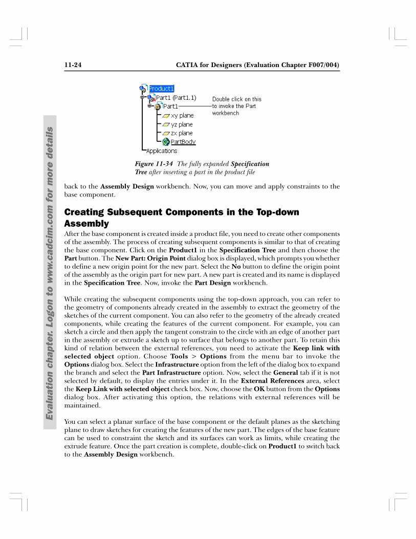
To create the model, you need to invoke the Part Design workbench. Click on the plus sign(+) displayed on the left of part name in the Specification Tree to expand it. Now, double-clickon the part name that is displayed inside the expanded branch to expand it further andsimultaneously the Part Design workbench is invoked. The fully expanded SpecificationTree is shown in Figure 11-34.
After the part is completed, double-click on the Product1 in the Specification Tree to switch
Menu: Insert > New PartToolbar: Product Structure Tools > Part
11-24 CATIA for Designers (Evaluation Chapter F007/004)
Eval
uati
on c
hapt
er.
Logo
n to
ww
w.c
adci
m.c
om f
or m
ore
deta
ils
back to the Assembly Design workbench. Now, you can move and apply constraints to thebase component.
Creating Subsequent Components in the Top-downAssemblyAfter the base component is created inside a product file, you need to create other componentsof the assembly. The process of creating subsequent components is similar to that of creatingthe base component. Click on the Product1 in the Specification Tree and then choose thePart button. The New Part: Origin Point dialog box is displayed, which prompts you whetherto define a new origin point for the new part. Select the No button to define the origin pointof the assembly as the origin part for new part. A new part is created and its name is displayedin the Specification Tree. Now, invoke the Part Design workbench.
While creating the subsequent components using the top-down approach, you can refer tothe geometry of components already created in the assembly to extract the geometry of thesketches of the current component. You can also refer to the geometry of the already createdcomponents, while creating the features of the current component. For example, you cansketch a circle and then apply the tangent constrain to the circle with an edge of another partin the assembly or extrude a sketch up to surface that belongs to another part. To retain thiskind of relation between the external references, you need to activate the Keep link withselected object option. Choose Tools > Options from the menu bar to invoke theOptions dialog box. Select the Infrastructure option from the left of the dialog box to expandthe branch and select the Part Infrastructure option. Now, select the General tab if it is notselected by default, to display the entries under it. In the External References area, selectthe Keep Link with selected object check box. Now, choose the OK button from the Optionsdialog box. After activating this option, the relations with external references will bemaintained.
You can select a planar surface of the base component or the default planes as the sketchingplane to draw sketches for creating the features of the new part. The edges of the base featurecan be used to constraint the sketch and its surfaces can work as limits, while creating theextrude feature. Once the part creation is complete, double-click on Product1 to switch backto the Assembly Design workbench.
Figure 11-34 The fully expanded SpecificationTree after inserting a part in the product file
Assembly Modeling 11-25
Eval
uati
on c
hapt
er.
Logo
n to
ww
w.c
adci
m.c
om f
or m
ore
deta
ils
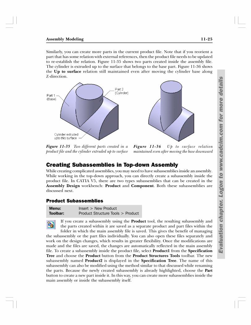
Similarly, you can create more parts in the current product file. Note that if you reorient apart that has some relation with external references, then the product file needs to be updatedto re-establish the relation. Figure 11-35 shows two parts created inside the assembly file.The cylinder is extruded up to the surface that belongs to the base part. Figure 11-36 showsthe Up to surface relation still maintained even after moving the cylinder base alongZ-direction.
Creating Subassemblies in Top-down AssemblyWhile creating complicated assemblies, you may need to have subassemblies inside an assembly.While working in the top-down approach, you can directly create a subassembly inside theproduct file. In CATIA V5, there are two types subassemblies that can be created in theAssembly Design workbench: Product and Component. Both these subassemblies arediscussed next.
Product Subassemblies
If you create a subassembly using the Product tool, the resulting subassembly andthe parts created within it are saved as a separate product and part files within thefolder in which the main assembly file is saved. This gives the benefit of managing
the subassembly or the part files individually. You can also open these files separately andwork on the design changes, which results in greater flexibility. Once the modifications aremade and the files are saved, the changes are automatically reflected in the main assemblyfile. To create a subassembly inside the product file, select Product1 from the SpecificationTree and choose the Product button from the Product Structures Tools toolbar. The newsubassembly named Product2 is displayed in the Specification Tree. The name of thissubassembly can also be modified using the method similar to that discussed while renamingthe parts. Because the newly created subassembly is already highlighted, choose the Partbutton to create a new part inside it. In this way, you can create more subassemblies inside themain assembly or inside the subassembly itself.
Figure 11-36 Up to surface relationmaintained even after moving the base downward
Figure 11-35 Two different parts created in aproduct file and the cylinder extruded up to surface
Menu: Insert > New ProductToolbar: Product Structure Tools > Product
11-26 CATIA for Designers (Evaluation Chapter F007/004)
Eval
uati
on c
hapt
er.
Logo
n to
ww
w.c
adci
m.c
om f
or m
ore
deta
ils
NoteYou can activate the subassemblies by double-clicking on the name of the subassembly in theSpecification Tree. To switch back to the main assembly, double-click on the name of the mainassembly in the Specification Tree.
Component Subassemblies
If you create a subassembly using the Component tool, the resulting subassemblybecomes an integral part of the main assembly file and will not be saved as separateproduct file. However, the individual parts are saved as separate part files. If you
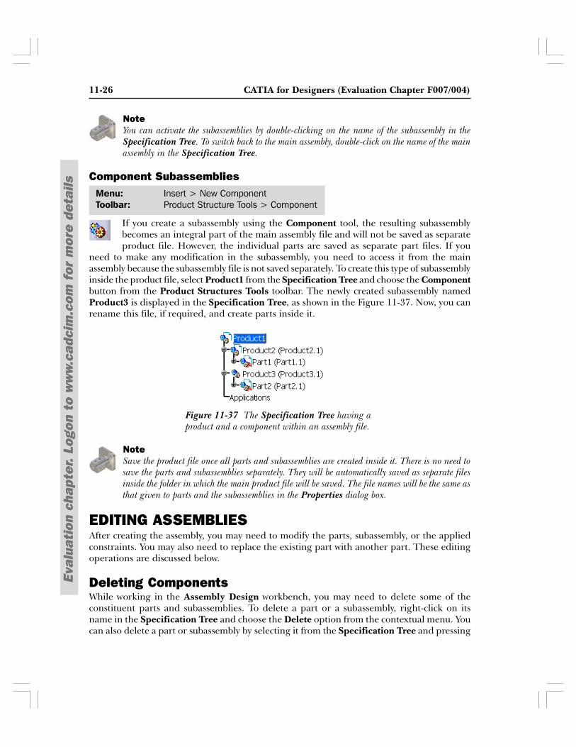
need to make any modification in the subassembly, you need to access it from the mainassembly because the subassembly file is not saved separately. To create this type of subassemblyinside the product file, select Product1 from the Specification Tree and choose the Componentbutton from the Product Structures Tools toolbar. The newly created subassembly namedProduct3 is displayed in the Specification Tree, as shown in the Figure 11-37. Now, you canrename this file, if required, and create parts inside it.
NoteSave the product file once all parts and subassemblies are created inside it. There is no need tosave the parts and subassemblies separately. They will be automatically saved as separate filesinside the folder in which the main product file will be saved. The file names will be the same asthat given to parts and the subassemblies in the Properties dialog box.
EDITING ASSEMBLIESAfter creating the assembly, you may need to modify the parts, subassembly, or the appliedconstraints. You may also need to replace the existing part with another part. These editingoperations are discussed below.
Deleting ComponentsWhile working in the Assembly Design workbench, you may need to delete some of theconstituent parts and subassemblies. To delete a part or a subassembly, right-click on itsname in the Specification Tree and choose the Delete option from the contextual menu. Youcan also delete a part or subassembly by selecting it from the Specification Tree and pressing
Figure 11-37 The Specification Tree having aproduct and a component within an assembly file.
Menu: Insert > New ComponentToolbar: Product Structure Tools > Component
Assembly Modeling 11-27
Eval
uati
on c
hapt
er.
Logo
n to
ww
w.c
adci
m.c
om f
or m
ore
deta
ils
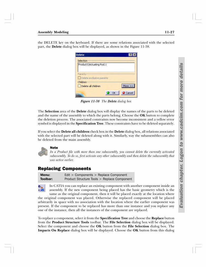
the DELETE key on the keyboard. If there are some relations associated with the selectedpart, the Delete dialog box will be displayed, as shown in the Figure 11-38.
The Selection area of the Delete dialog box will display the names of the parts to be deletedand the name of the assembly to which the parts belong. Choose the OK button to completethe deletion process. The associated constraints now become inconsistent and a yellow errorsymbol is displayed in the Specification Tree. These constraints have to be deleted separately.
If you select the Delete all children check box in the Delete dialog box, all relations associatedwith the selected part will be deleted along with it. Similarly, way the subassemblies can alsobe deleted from the main assembly.
NoteIn a Product file with more than one subassembly, you cannot delete the currently activatedsubassembly. To do so, first activate any other subassembly and then delete the subassembly thatwas active earlier.
Replacing Components
In CATIA you can replace an existing component with another component inside anassembly. If the new component being placed has the basic geometry which is thesame as the original component, then it will be placed exactly at the location where
the original component was placed. Otherwise the replaced component will be placedarbitrarily in space with no association with the location where the earlier component waspresent. If the component to be replaced has more than one instance and you replace anyone of the instance, then all the instances of the component are replaced.
To replace a component, select it from the Specification Tree and choose the Replace buttonfrom the Product Structure Tools toolbar. The File Selection dialog box will be displayed.Select the component and choose the OK button from the File Selection dialog box. TheImpacts On Replace dialog box will be displayed. Choose the OK button from this dialog
Menu: Edit > Components > Replace ComponentToolbar: Product Structure Tools > Replace Component
Figure 11-38 The Delete dialog box
11-28 CATIA for Designers (Evaluation Chapter F007/004)
Eval
uati
on c
hapt
er.
Logo
n to
ww
w.c
adci
m.c
om f
or m
ore
deta
ils
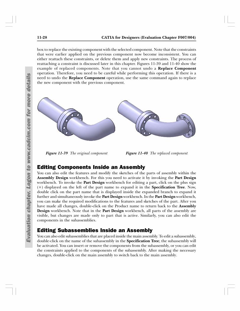
box to replace the existing component with the selected component. Note that the constraintsthat were earlier applied on the previous component now become inconsistent. You caneither reattach these constraints, or delete them and apply new constraints. The process ofreattaching a constraint is discussed later in this chapter. Figures 11-39 and 11-40 show theexample of replaced components. Note that you cannot undo a Replace Componentoperation. Therefore, you need to be careful while performing this operation. If there is aneed to undo the Replace Component operation, use the same command again to replacethe new component with the previous component.
Editing Components Inside an AssemblyYou can also edit the features and modify the sketches of the parts of assembly within theAssembly Design workbench. For this you need to activate it by invoking the Part Designworkbench. To invoke the Part Design workbench for editing a part, click on the plus sign(+) displayed on the left of the part name to expand it in the Specification Tree. Now,double click on the part name that is displayed inside the expanded branch to expand itfurther and simultaneously invoke the Part Design workbench. In the Part Design workbench,you can make the required modifications to the features and sketches of the part. After youhave made all changes, double-click on the Product name to return back to the AssemblyDesign workbench. Note that in the Part Design workbench, all parts of the assembly arevisible, but changes are made only to part that is active. Similarly, you can also edit thecomponents in the subassemblies.
Editing Subassemblies Inside an AssemblyYou can also edit subassemblies that are placed inside the main assembly. To edit a subassembly,double-click on the name of the subassembly in the Specification Tree; the subassembly willbe activated. You can insert or remove the components from the subassembly, or you can editthe constraints applied to the components of the subassembly. After making the necessarychanges, double-click on the main assembly to switch back to the main assembly.
Figure 11-40 The replaced componentFigure 11-39 The original component
Assembly Modeling 11-29
Eval
uati
on c
hapt
er.
Logo
n to
ww
w.c
adci
m.c
om f
or m
ore
deta
ils
NoteThe changes made to a part or subassembly inside the product file are also reflected in theirrespective part and product files. Therefore, the changes will take place whereever these partsand subassemblies have been used.
Editing the Assembly ConstraintsIn an assembly, the constituent parts are positioned at their respective locations using theconstraints. Many a times, you need to replace the existing constraint with another constraintor to change the entities to which the constraints are applied. The methods to modify theconstraints are discussed below.
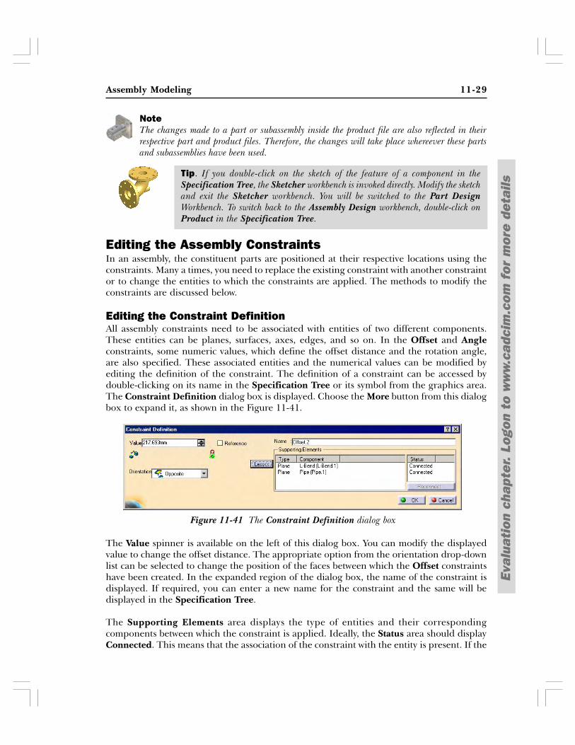
Editing the Constraint DefinitionAll assembly constraints need to be associated with entities of two different components.These entities can be planes, surfaces, axes, edges, and so on. In the Offset and Angleconstraints, some numeric values, which define the offset distance and the rotation angle,are also specified. These associated entities and the numerical values can be modified byediting the definition of the constraint. The definition of a constraint can be accessed bydouble-clicking on its name in the Specification Tree or its symbol from the graphics area.The Constraint Definition dialog box is displayed. Choose the More button from this dialogbox to expand it, as shown in the Figure 11-41.
The Value spinner is available on the left of this dialog box. You can modify the displayedvalue to change the offset distance. The appropriate option from the orientation drop-downlist can be selected to change the position of the faces between which the Offset constraintshave been created. In the expanded region of the dialog box, the name of the constraint isdisplayed. If required, you can enter a new name for the constraint and the same will bedisplayed in the Specification Tree.
The Supporting Elements area displays the type of entities and their correspondingcomponents between which the constraint is applied. Ideally, the Status area should displayConnected. This means that the association of the constraint with the entity is present. If the
Figure 11-41 The Constraint Definition dialog box
Tip. If you double-click on the sketch of the feature of a component in theSpecification Tree, the Sketcher workbench is invoked directly. Modify the sketchand exit the Sketcher workbench. You will be switched to the Part DesignWorkbench. To switch back to the Assembly Design workbench, double-click onProduct in the Specification Tree.
11-30 CATIA for Designers (Evaluation Chapter F007/004)
Eval
uati
on c
hapt
er.
Logo
n to
ww
w.c
adci
m.c
om f
or m
ore
deta
ils
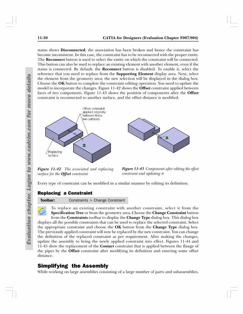
status shows Disconnected, the association has been broken and hence the constraint hasbecome inconsistent. In this case, the constraint has to be reconnected with the proper entity.The Reconnect button is used to select the entity on which the constraint will be connected.This button can also be used to replace an existing element with another element, even if thestatus is connected. By default, the Reconnect button is disabled. To enable it, select thereference that you need to replace from the Supporting Element display area. Next, selectthe element from the geometry area; the new selection will be displayed in the dialog box.Choose the OK button to complete the constraint editing operation. You need to update themodel to incorporate the changes. Figure 11-42 shows the Offset constraint applied betweenfaces of two components. Figure 11-43 shows the position of components after the Offsetconstraint is reconnected to another surface, and the offset distance is modified.
Every type of constraint can be modified in a similar manner by editing its definition.
Replacing a Constraint
To replace an existing constraint with another constraint, select it from theSpecification Tree or from the geometry area. Choose the Change Constraint buttonfrom the Constraints toolbar to display the Change Type dialog box. This dialog box
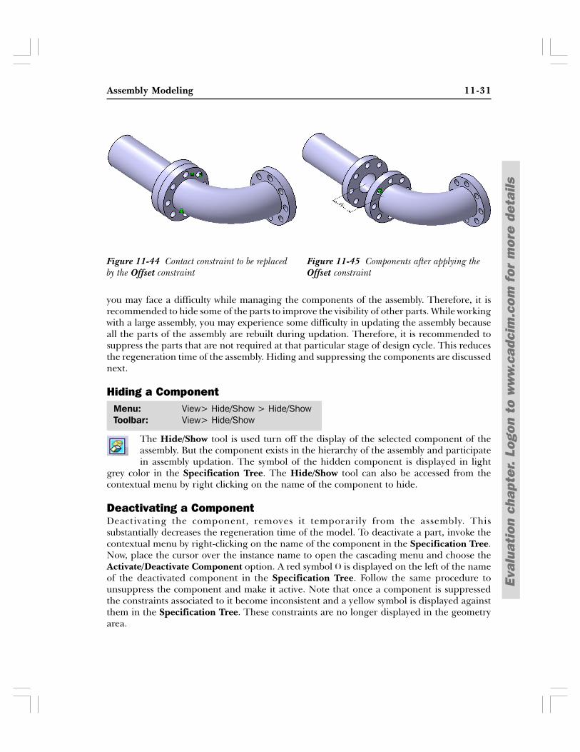
displays all the possible constraints that can be used to replace the selected constraint. Selectthe appropriate constraint and choose the OK button from the Change Type dialog box.The previously applied constraint will now be replaced by the new constraint. You can changethe definition of the replaced constraint as per requirement. After making the changes,update the assembly to bring the newly applied constraint into effect. Figures 11-44 and11-45 show the replacement of the Contact constraint that is applied between the flange ofthe pipes by the Offset constraint after modifying its definition and entering some offsetdistance.
Simplifying the AssemblyWhile working on large assemblies consisting of a large number of parts and subassemblies,
Figure 11-43 Components after editing the offsetconstraint and updating it
Figure 11-42 The associated and replacingsurface for the Offset constraint
Toolbar: Constraints > Change Constraint
Assembly Modeling 11-31
Eval
uati
on c
hapt
er.
Logo
n to
ww
w.c
adci
m.c
om f
or m
ore
deta
ils
you may face a difficulty while managing the components of the assembly. Therefore, it isrecommended to hide some of the parts to improve the visibility of other parts. While workingwith a large assembly, you may experience some difficulty in updating the assembly becauseall the parts of the assembly are rebuilt during updation. Therefore, it is recommended tosuppress the parts that are not required at that particular stage of design cycle. This reducesthe regeneration time of the assembly. Hiding and suppressing the components are discussednext.
Hiding a Component
The Hide/Show tool is used turn off the display of the selected component of theassembly. But the component exists in the hierarchy of the assembly and participatein assembly updation. The symbol of the hidden component is displayed in light
grey color in the Specification Tree. The Hide/Show tool can also be accessed from thecontextual menu by right clicking on the name of the component to hide.
Deactivating a ComponentDeactivating the component, removes it temporarily from the assembly. Thissubstantially decreases the regeneration time of the model. To deactivate a part, invoke thecontextual menu by right-clicking on the name of the component in the Specification Tree.Now, place the cursor over the instance name to open the cascading menu and choose theActivate/Deactivate Component option. A red symbol is displayed on the left of the nameof the deactivated component in the Specification Tree. Follow the same procedure tounsuppress the component and make it active. Note that once a component is suppressedthe constraints associated to it become inconsistent and a yellow symbol is displayed againstthem in the Specification Tree. These constraints are no longer displayed in the geometryarea.
Menu: View> Hide/Show > Hide/ShowToolbar: View> Hide/Show
Figure 11-45 Components after applying theOffset constraint
Figure 11-44 Contact constraint to be replacedby the Offset constraint
11-32 CATIA for Designers (Evaluation Chapter F007/004)
Eval
uati
on c
hapt
er.
Logo
n to
ww
w.c
adci
m.c
om f
or m
ore
deta
ils
Menu: Analyze > SectioningToolbar: Space Analysis > Sectioning
Interference Detection
It is recommended to check the interference and clearance between the componentsof the assembly to make sure that the components are not interfering with each otherand the right type of fit is maintained between the mating parts. The interference is
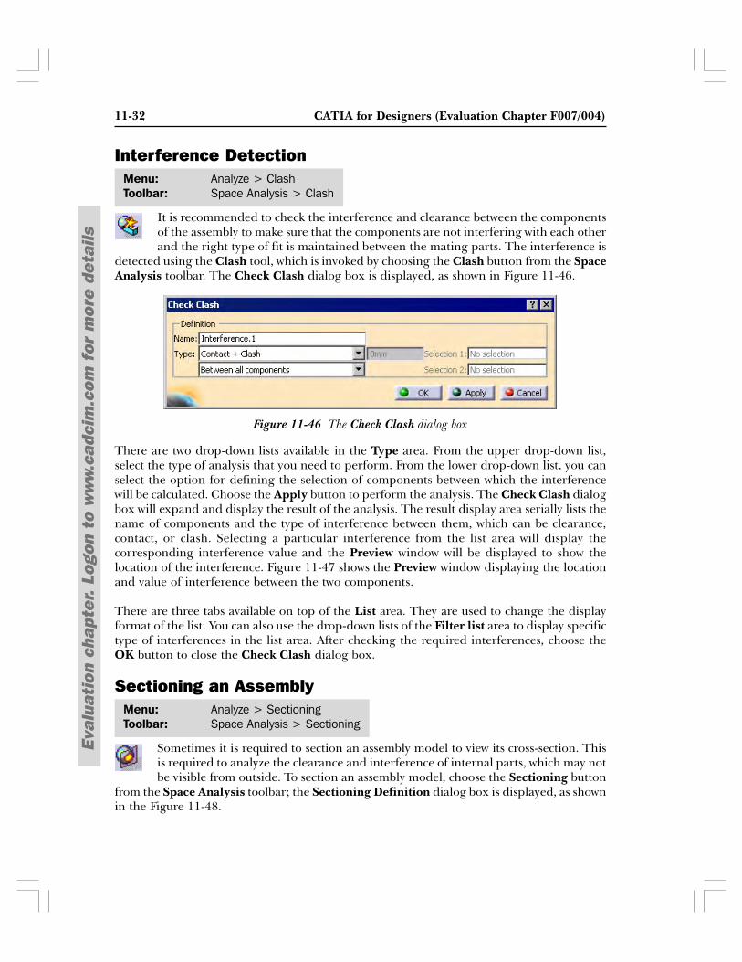
detected using the Clash tool, which is invoked by choosing the Clash button from the SpaceAnalysis toolbar. The Check Clash dialog box is displayed, as shown in Figure 11-46.
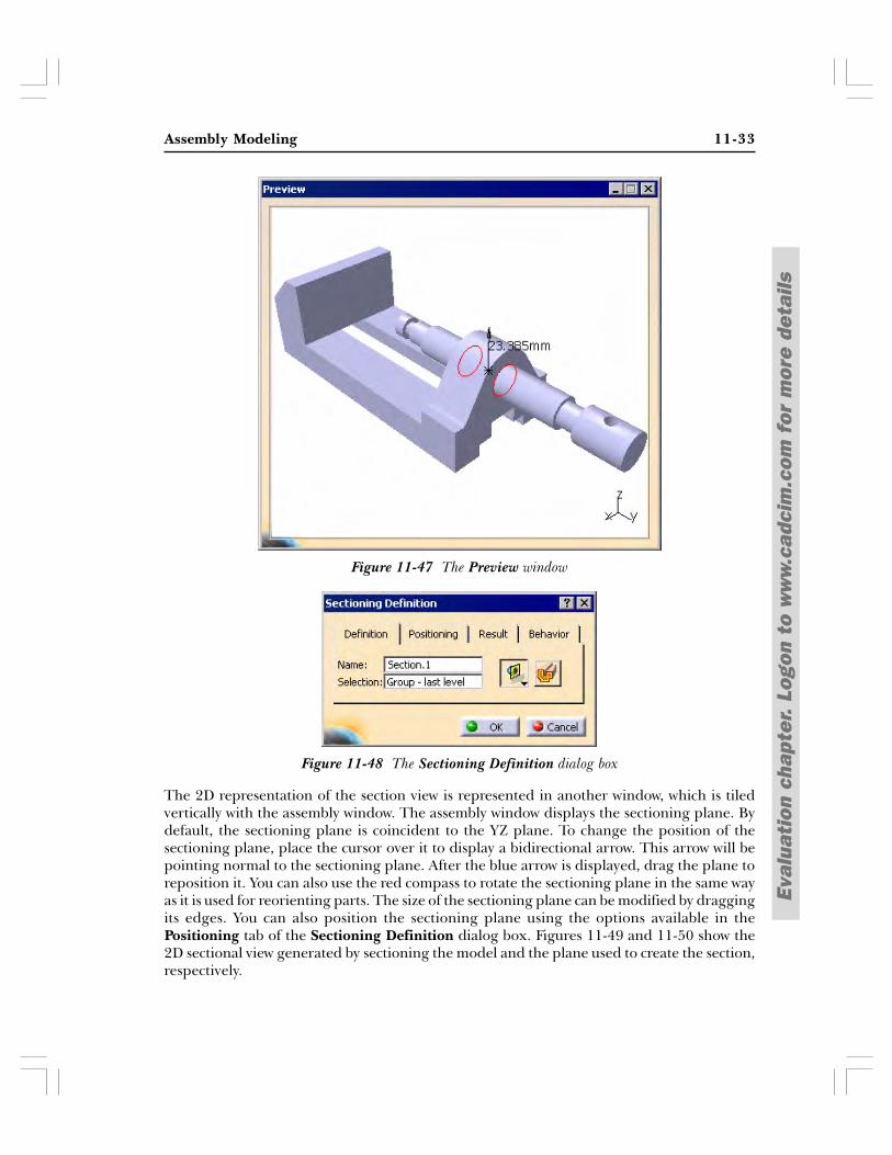
There are two drop-down lists available in the Type area. From the upper drop-down list,select the type of analysis that you need to perform. From the lower drop-down list, you canselect the option for defining the selection of components between which the interferencewill be calculated. Choose the Apply button to perform the analysis. The Check Clash dialogbox will expand and display the result of the analysis. The result display area serially lists thename of components and the type of interference between them, which can be clearance,contact, or clash. Selecting a particular interference from the list area will display thecorresponding interference value and the Preview window will be displayed to show thelocation of the interference. Figure 11-47 shows the Preview window displaying the locationand value of interference between the two components.
There are three tabs available on top of the List area. They are used to change the displayformat of the list. You can also use the drop-down lists of the Filter list area to display specifictype of interferences in the list area. After checking the required interferences, choose theOK button to close the Check Clash dialog box.
Sectioning an Assembly
Sometimes it is required to section an assembly model to view its cross-section. Thisis required to analyze the clearance and interference of internal parts, which may notbe visible from outside. To section an assembly model, choose the Sectioning button
from the Space Analysis toolbar; the Sectioning Definition dialog box is displayed, as shownin the Figure 11-48.
Figure 11-46 The Check Clash dialog box
Menu: Analyze > ClashToolbar: Space Analysis > Clash
Assembly Modeling 11-33
Eval
uati
on c
hapt
er.
Logo
n to
ww
w.c
adci
m.c
om f
or m
ore
deta
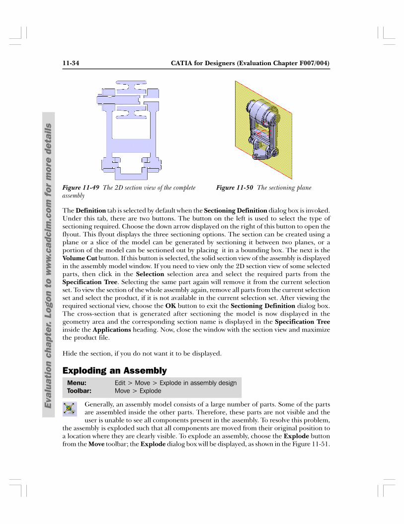
ilsThe 2D representation of the section view is represented in another window, which is tiledvertically with the assembly window. The assembly window displays the sectioning plane. Bydefault, the sectioning plane is coincident to the YZ plane. To change the position of thesectioning plane, place the cursor over it to display a bidirectional arrow. This arrow will bepointing normal to the sectioning plane. After the blue arrow is displayed, drag the plane toreposition it. You can also use the red compass to rotate the sectioning plane in the same wayas it is used for reorienting parts. The size of the sectioning plane can be modified by draggingits edges. You can also position the sectioning plane using the options available in thePositioning tab of the Sectioning Definition dialog box. Figures 11-49 and 11-50 show the2D sectional view generated by sectioning the model and the plane used to create the section,respectively.
Figure 11-48 The Sectioning Definition dialog box
Figure 11-47 The Preview window
11-34 CATIA for Designers (Evaluation Chapter F007/004)
Eval
uati
on c
hapt
er.
Logo
n to
ww
w.c
adci
m.c
om f
or m
ore
deta
ils
The Definition tab is selected by default when the Sectioning Definition dialog box is invoked.Under this tab, there are two buttons. The button on the left is used to select the type ofsectioning required. Choose the down arrow displayed on the right of this button to open theflyout. This flyout displays the three sectioning options. The section can be created using aplane or a slice of the model can be generated by sectioning it between two planes, or aportion of the model can be sectioned out by placing it in a bounding box. The next is theVolume Cut button. If this button is selected, the solid section view of the assembly is displayedin the assembly model window. If you need to view only the 2D section view of some selectedparts, then click in the Selection selection area and select the required parts from theSpecification Tree. Selecting the same part again will remove it from the current selectionset. To view the section of the whole assembly again, remove all parts from the current selectionset and select the product, if it is not available in the current selection set. After viewing therequired sectional view, choose the OK button to exit the Sectioning Definition dialog box.The cross-section that is generated after sectioning the model is now displayed in thegeometry area and the corresponding section name is displayed in the Specification Treeinside the Applications heading. Now, close the window with the section view and maximizethe product file.
Hide the section, if you do not want it to be displayed.
Exploding an Assembly
Generally, an assembly model consists of a large number of parts. Some of the partsare assembled inside the other parts. Therefore, these parts are not visible and theuser is unable to see all components present in the assembly. To resolve this problem,
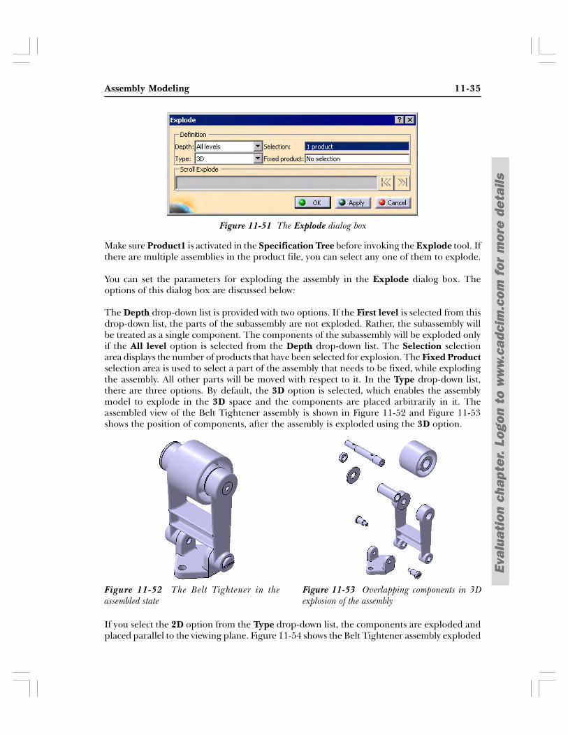
the assembly is exploded such that all components are moved from their original position toa location where they are clearly visible. To explode an assembly, choose the Explode buttonfrom the Move toolbar; the Explode dialog box will be displayed, as shown in the Figure 11-51.
Figure 11-50 The sectioning planeFigure 11-49 The 2D section view of the completeassembly
Menu: Edit > Move > Explode in assembly designToolbar: Move > Explode
Assembly Modeling 11-35
Eval
uati
on c
hapt
er.
Logo
n to
ww
w.c
adci
m.c
om f
or m
ore
deta
ils
Make sure Product1 is activated in the Specification Tree before invoking the Explode tool. Ifthere are multiple assemblies in the product file, you can select any one of them to explode.
You can set the parameters for exploding the assembly in the Explode dialog box. Theoptions of this dialog box are discussed below:
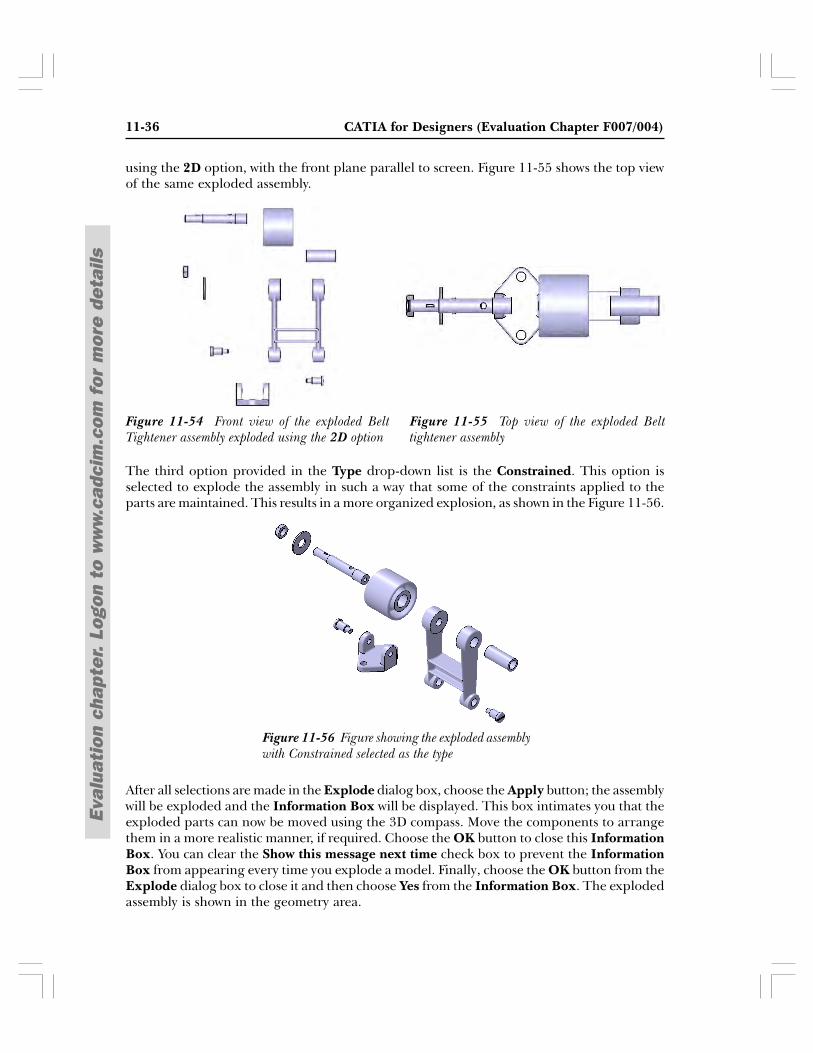
The Depth drop-down list is provided with two options. If the First level is selected from thisdrop-down list, the parts of the subassembly are not exploded. Rather, the subassembly willbe treated as a single component. The components of the subassembly will be exploded onlyif the All level option is selected from the Depth drop-down list. The Selection selectionarea displays the number of products that have been selected for explosion. The Fixed Productselection area is used to select a part of the assembly that needs to be fixed, while explodingthe assembly. All other parts will be moved with respect to it. In the Type drop-down list,there are three options. By default, the 3D option is selected, which enables the assemblymodel to explode in the 3D space and the components are placed arbitrarily in it. Theassembled view of the Belt Tightener assembly is shown in Figure 11-52 and Figure 11-53shows the position of components, after the assembly is exploded using the 3D option.
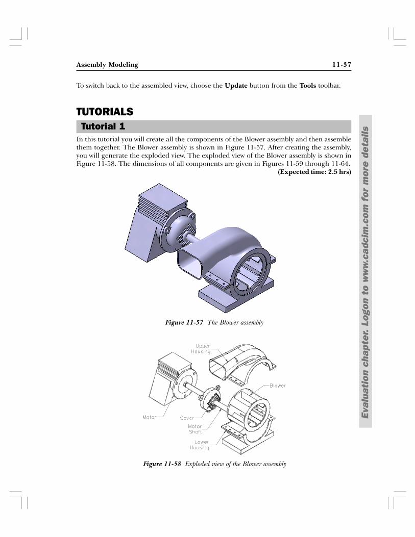
If you select the 2D option from the Type drop-down list, the components are exploded andplaced parallel to the viewing plane. Figure 11-54 shows the Belt Tightener assembly exploded
Figure 11-53 Overlapping components in 3Dexplosion of the assembly
Figure 11-52 The Belt Tightener in theassembled state
Figure 11-51 The Explode dialog box
11-36 CATIA for Designers (Evaluation Chapter F007/004)
Eval
uati
on c
hapt
er.
Logo
n to
ww
w.c
adci
m.c
om f
or m
ore
deta
ils
using the 2D option, with the front plane parallel to screen. Figure 11-55 shows the top viewof the same exploded assembly.
The third option provided in the Type drop-down list is the Constrained. This option isselected to explode the assembly in such a way that some of the constraints applied to theparts are maintained. This results in a more organized explosion, as shown in the Figure 11-56.
After all selections are made in the Explode dialog box, choose the Apply button; the assemblywill be exploded and the Information Box will be displayed. This box intimates you that theexploded parts can now be moved using the 3D compass. Move the components to arrangethem in a more realistic manner, if required. Choose the OK button to close this InformationBox. You can clear the Show this message next time check box to prevent the InformationBox from appearing every time you explode a model. Finally, choose the OK button from theExplode dialog box to close it and then choose Yes from the Information Box. The explodedassembly is shown in the geometry area.
Figure 11-55 Top view of the exploded Belttightener assembly
Figure 11-54 Front view of the exploded BeltTightener assembly exploded using the 2D option
Figure 11-56 Figure showing the exploded assemblywith Constrained selected as the type
Assembly Modeling 11-37
Eval
uati
on c
hapt
er.
Logo
n to
ww
w.c
adci
m.c
om f
or m
ore
deta
ils
Tutorial 1
Figure 11-57 The Blower assembly
Figure 11-58 Exploded view of the Blower assembly
To switch back to the assembled view, choose the Update button from the Tools toolbar.
TUTORIALS
In this tutorial you will create all the components of the Blower assembly and then assemblethem together. The Blower assembly is shown in Figure 11-57. After creating the assembly,you will generate the exploded view. The exploded view of the Blower assembly is shown inFigure 11-58. The dimensions of all components are given in Figures 11-59 through 11-64.
(Expected time: 2.5 hrs)
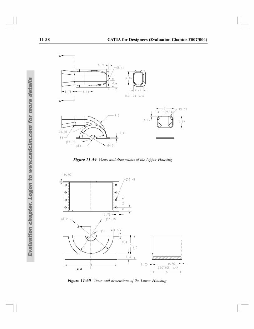
11-38 CATIA for Designers (Evaluation Chapter F007/004)
Eval
uati
on c
hapt
er.
Logo
n to
ww
w.c
adci
m.c
om f
or m
ore
deta
ils
Figure 11-59 Views and dimensions of the Upper Housing
Figure 11-60 Views and dimensions of the Lower Housing
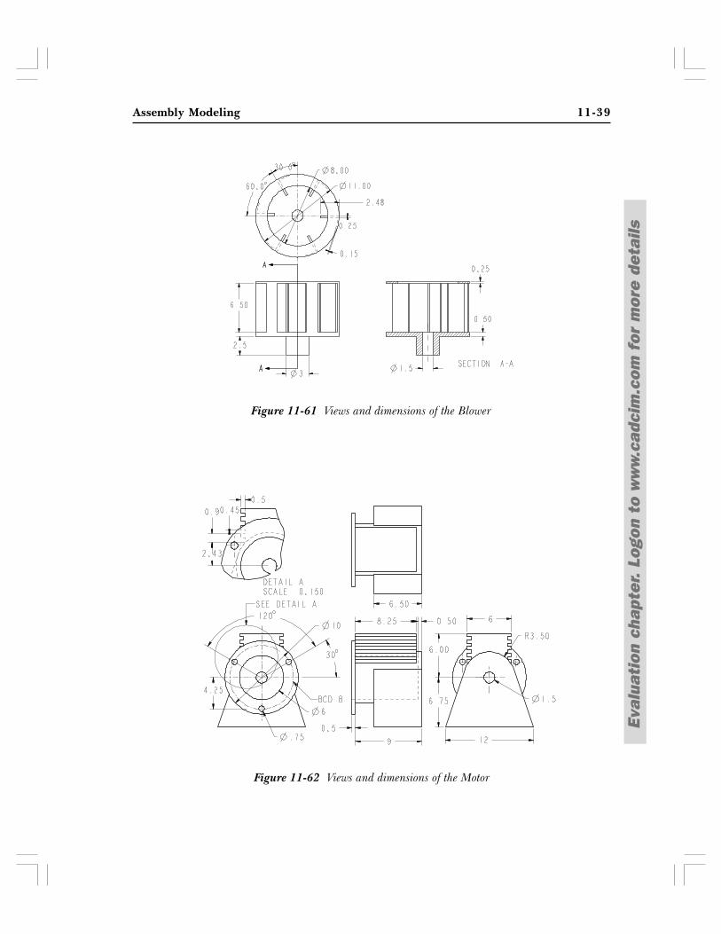
Assembly Modeling 11-39
Eval
uati
on c
hapt
er.
Logo
n to
ww
w.c
adci
m.c
om f
or m
ore
deta
ils
Figure 11-61 Views and dimensions of the Blower
Figure 11-62 Views and dimensions of the Motor
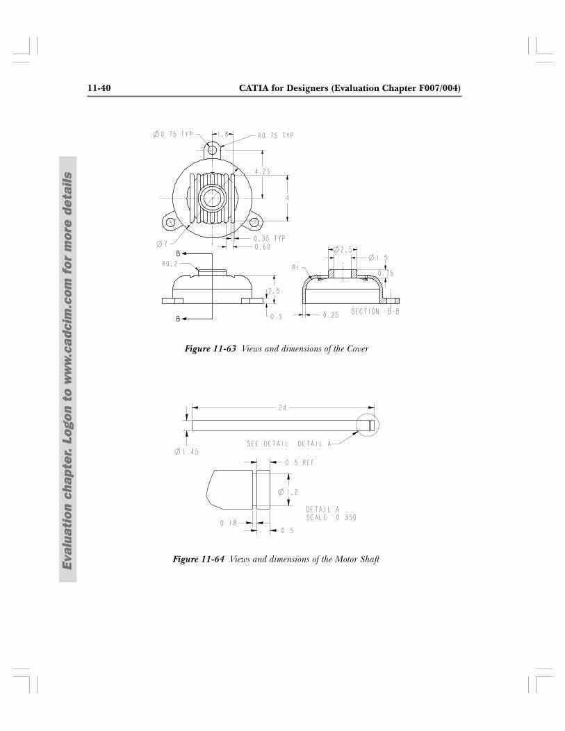
11-40 CATIA for Designers (Evaluation Chapter F007/004)
Eval
uati
on c
hapt
er.
Logo
n to
ww
w.c
adci
m.c
om f
or m
ore
deta
ils
Figure 11-63 Views and dimensions of the Cover
Figure 11-64 Views and dimensions of the Motor Shaft
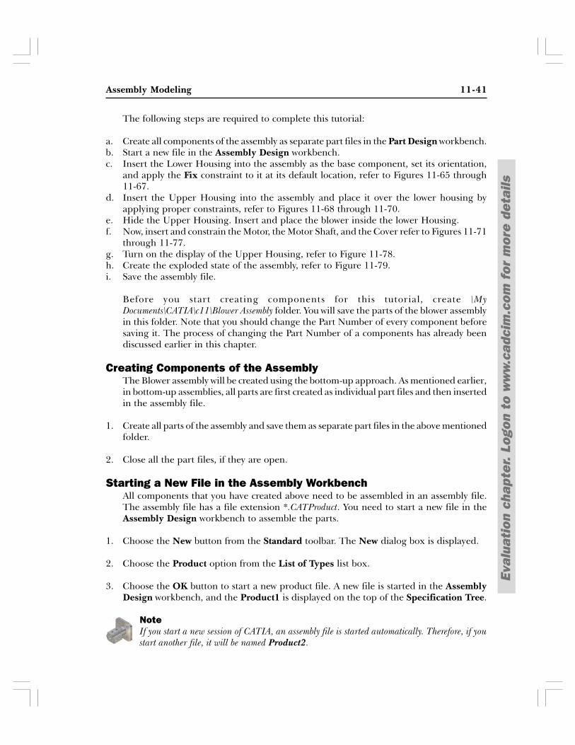
Assembly Modeling 11-41
Eval
uati
on c
hapt
er.
Logo
n to
ww
w.c
adci
m.c
om f
or m
ore
deta
ils
The following steps are required to complete this tutorial:
a. Create all components of the assembly as separate part files in the Part Design workbench.b. Start a new file in the Assembly Design workbench.c. Insert the Lower Housing into the assembly as the base component, set its orientation,
and apply the Fix constraint to it at its default location, refer to Figures 11-65 through11-67.
d. Insert the Upper Housing into the assembly and place it over the lower housing byapplying proper constraints, refer to Figures 11-68 through 11-70.
e. Hide the Upper Housing. Insert and place the blower inside the lower Housing.f. Now, insert and constrain the Motor, the Motor Shaft, and the Cover refer to Figures 11-71
through 11-77.g. Turn on the display of the Upper Housing, refer to Figure 11-78.h. Create the exploded state of the assembly, refer to Figure 11-79.i. Save the assembly file.
Before you start creating components for this tutorial, create \MyDocuments\CATIA\c11\Blower Assembly folder. You will save the parts of the blower assemblyin this folder. Note that you should change the Part Number of every component beforesaving it. The process of changing the Part Number of a components has already beendiscussed earlier in this chapter.
Creating Components of the AssemblyThe Blower assembly will be created using the bottom-up approach. As mentioned earlier,in bottom-up assemblies, all parts are first created as individual part files and then insertedin the assembly file.
1. Create all parts of the assembly and save them as separate part files in the above mentionedfolder.
2. Close all the part files, if they are open.
Starting a New File in the Assembly WorkbenchAll components that you have created above need to be assembled in an assembly file.The assembly file has a file extension *.CATProduct. You need to start a new file in theAssembly Design workbench to assemble the parts.
1. Choose the New button from the Standard toolbar. The New dialog box is displayed.
2. Choose the Product option from the List of Types list box.
3. Choose the OK button to start a new product file. A new file is started in the AssemblyDesign workbench, and the Product1 is displayed on the top of the Specification Tree.
NoteIf you start a new session of CATIA, an assembly file is started automatically. Therefore, if youstart another file, it will be named Product2.
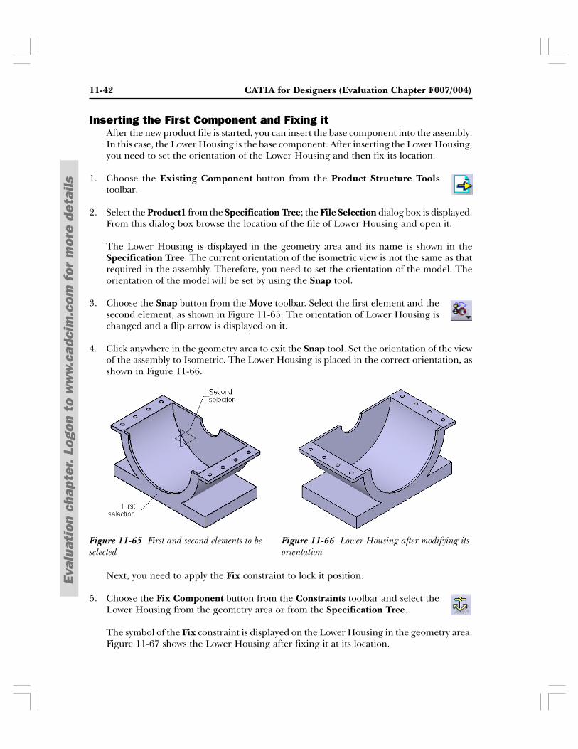
11-42 CATIA for Designers (Evaluation Chapter F007/004)
Eval
uati
on c
hapt
er.
Logo
n to
ww
w.c
adci
m.c
om f
or m
ore
deta
ils
Inserting the First Component and Fixing itAfter the new product file is started, you can insert the base component into the assembly.In this case, the Lower Housing is the base component. After inserting the Lower Housing,you need to set the orientation of the Lower Housing and then fix its location.
1. Choose the Existing Component button from the Product Structure Toolstoolbar.
2. Select the Product1 from the Specification Tree; the File Selection dialog box is displayed.From this dialog box browse the location of the file of Lower Housing and open it.
The Lower Housing is displayed in the geometry area and its name is shown in theSpecification Tree. The current orientation of the isometric view is not the same as thatrequired in the assembly. Therefore, you need to set the orientation of the model. Theorientation of the model will be set by using the Snap tool.
3. Choose the Snap button from the Move toolbar. Select the first element and thesecond element, as shown in Figure 11-65. The orientation of Lower Housing ischanged and a flip arrow is displayed on it.
4. Click anywhere in the geometry area to exit the Snap tool. Set the orientation of the viewof the assembly to Isometric. The Lower Housing is placed in the correct orientation, asshown in Figure 11-66.
Next, you need to apply the Fix constraint to lock it position.
5. Choose the Fix Component button from the Constraints toolbar and select theLower Housing from the geometry area or from the Specification Tree.
The symbol of the Fix constraint is displayed on the Lower Housing in the geometry area.Figure 11-67 shows the Lower Housing after fixing it at its location.
Figure 11-66 Lower Housing after modifying itsorientation
Figure 11-65 First and second elements to beselected
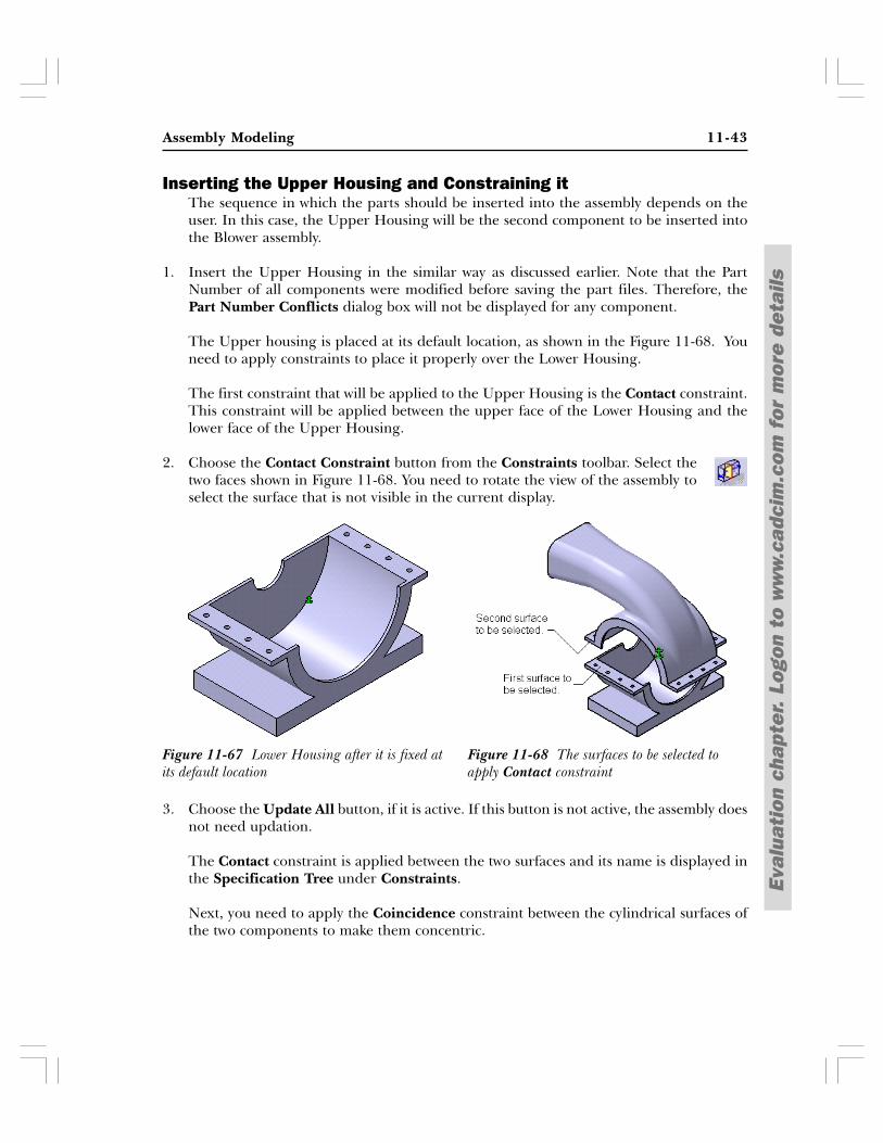
Assembly Modeling 11-43
Eval
uati
on c
hapt
er.
Logo
n to
ww
w.c
adci
m.c
om f
or m
ore
deta
ils
Inserting the Upper Housing and Constraining itThe sequence in which the parts should be inserted into the assembly depends on theuser. In this case, the Upper Housing will be the second component to be inserted intothe Blower assembly.
1. Insert the Upper Housing in the similar way as discussed earlier. Note that the PartNumber of all components were modified before saving the part files. Therefore, thePart Number Conflicts dialog box will not be displayed for any component.
The Upper housing is placed at its default location, as shown in the Figure 11-68. Youneed to apply constraints to place it properly over the Lower Housing.
The first constraint that will be applied to the Upper Housing is the Contact constraint.This constraint will be applied between the upper face of the Lower Housing and thelower face of the Upper Housing.
2. Choose the Contact Constraint button from the Constraints toolbar. Select thetwo faces shown in Figure 11-68. You need to rotate the view of the assembly toselect the surface that is not visible in the current display.
3. Choose the Update All button, if it is active. If this button is not active, the assembly doesnot need updation.
The Contact constraint is applied between the two surfaces and its name is displayed inthe Specification Tree under Constraints.
Next, you need to apply the Coincidence constraint between the cylindrical surfaces ofthe two components to make them concentric.
Figure 11-68 The surfaces to be selected toapply Contact constraint
Figure 11-67 Lower Housing after it is fixed atits default location
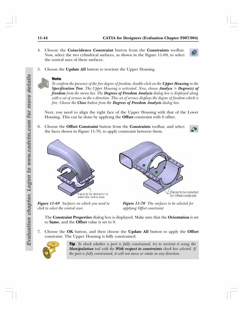
11-44 CATIA for Designers (Evaluation Chapter F007/004)
Eval
uati
on c
hapt
er.
Logo
n to
ww
w.c
adci
m.c
om f
or m
ore
deta
ils
Tip. To check whether a part is fully constrained, try to reorient it using theManipulation tool with the With respect to constraints check box selected. Ifthe part is fully constrained, it will not move or rotate in any direction.
4. Choose the Coincidence Constraint button from the Constraints toolbar.Now, select the two cylindrical surfaces, as shown in the Figure 11-69, to selectthe central axes of these surfaces.
5. Choose the Update All button to reorient the Upper Housing.
NoteTo confirm the presence of the free degree of freedom, double-click on the Upper Housing in theSpecification Tree. The Upper Housing is activated. Now, choose Analyze > Degree(s) offreedom from the menu bar. The Degrees of Freedom Analysis dialog box is displayed alongwith a set of arrows in the x direction. This set of arrows displays the degree of freedom which isfree. Choose the Close button from the Degrees of Freedom Analysis dialog box.
Next, you need to align the right face of the Upper Housing with that of the LowerHousing. This can be done by applying the Offset constraint with 0 offset.
6. Choose the Offset Constraint button from the Constraints toolbar, and selectthe faces shown in Figure 11-70, to apply constraint between them.
The Constraint Properties dialog box is displayed. Make sure that the Orientation is setto Same, and the Offset value is set to 0.
7. Choose the OK button, and then choose the Update All button to apply the Offsetconstraint. The Upper Housing is fully constrained.
Figure 11-70 The surfaces to be selected forapplying Offset constraint
Figure 11-69 Surfaces on which you need toclick to select the central axes
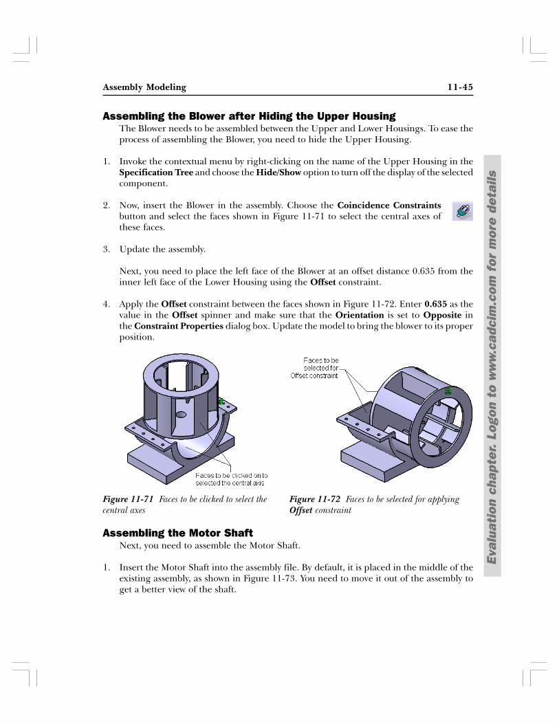
Assembly Modeling 11-45
Eval
uati
on c
hapt
er.
Logo
n to
ww
w.c
adci
m.c
om f
or m
ore
deta
ils
Assembling the Blower after Hiding the Upper HousingThe Blower needs to be assembled between the Upper and Lower Housings. To ease theprocess of assembling the Blower, you need to hide the Upper Housing.
1. Invoke the contextual menu by right-clicking on the name of the Upper Housing in theSpecification Tree and choose the Hide/Show option to turn off the display of the selectedcomponent.
2. Now, insert the Blower in the assembly. Choose the Coincidence Constraintsbutton and select the faces shown in Figure 11-71 to select the central axes ofthese faces.
3. Update the assembly.
Next, you need to place the left face of the Blower at an offset distance 0.635 from theinner left face of the Lower Housing using the Offset constraint.
4. Apply the Offset constraint between the faces shown in Figure 11-72. Enter 0.635 as thevalue in the Offset spinner and make sure that the Orientation is set to Opposite inthe Constraint Properties dialog box. Update the model to bring the blower to its properposition.
Assembling the Motor ShaftNext, you need to assemble the Motor Shaft.
1. Insert the Motor Shaft into the assembly file. By default, it is placed in the middle of theexisting assembly, as shown in Figure 11-73. You need to move it out of the assembly toget a better view of the shaft.
Figure 11-72 Faces to be selected for applyingOffset constraint
Figure 11-71 Faces to be clicked to select thecentral axes
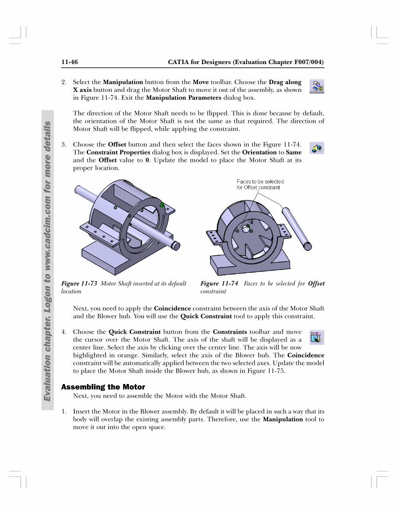
11-46 CATIA for Designers (Evaluation Chapter F007/004)
Eval
uati
on c
hapt
er.
Logo
n to
ww
w.c
adci
m.c
om f
or m
ore
deta
ils
2. Select the Manipulation button from the Move toolbar. Choose the Drag alongX axis button and drag the Motor Shaft to move it out of the assembly, as shownin Figure 11-74. Exit the Manipulation Parameters dialog box.
The direction of the Motor Shaft needs to be flipped. This is done because by default,the orientation of the Motor Shaft is not the same as that required. The direction ofMotor Shaft will be flipped, while applying the constraint.
3. Choose the Offset button and then select the faces shown in the Figure 11-74.The Constraint Properties dialog box is displayed. Set the Orientation to Sameand the Offset value to 0. Update the model to place the Motor Shaft at itsproper location.
Next, you need to apply the Coincidence constraint between the axis of the Motor Shaftand the Blower hub. You will use the Quick Constraint tool to apply this constraint.
4. Choose the Quick Constraint button from the Constraints toolbar and movethe cursor over the Motor Shaft. The axis of the shaft will be displayed as acenter line. Select the axis by clicking over the center line. The axis will be nowhighlighted in orange. Similarly, select the axis of the Blower hub. The Coincidenceconstraint will be automatically applied between the two selected axes. Update the modelto place the Motor Shaft inside the Blower hub, as shown in Figure 11-75.
Assembling the MotorNext, you need to assemble the Motor with the Motor Shaft.
1. Insert the Motor in the Blower assembly. By default it will be placed in such a way that itsbody will overlap the existing assembly parts. Therefore, use the Manipulation tool tomove it out into the open space.
Figure 11-74 Faces to be selected for Offsetconstraint
Figure 11-73 Motor Shaft inserted at its defaultlocation
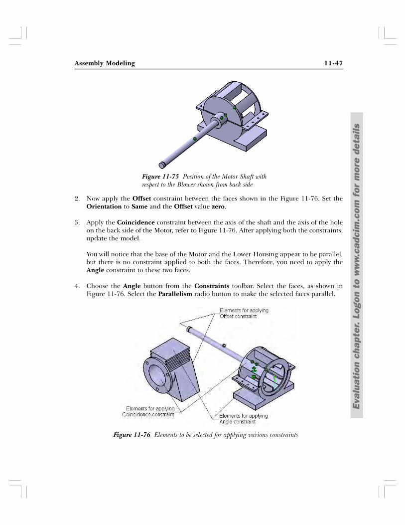
Assembly Modeling 11-47
Eval
uati
on c
hapt
er.
Logo
n to
ww
w.c
adci
m.c
om f
or m
ore
deta
ils
2. Now apply the Offset constraint between the faces shown in the Figure 11-76. Set theOrientation to Same and the Offset value zero.
3. Apply the Coincidence constraint between the axis of the shaft and the axis of the holeon the back side of the Motor, refer to Figure 11-76. After applying both the constraints,update the model.
You will notice that the base of the Motor and the Lower Housing appear to be parallel,but there is no constraint applied to both the faces. Therefore, you need to apply theAngle constraint to these two faces.
4. Choose the Angle button from the Constraints toolbar. Select the faces, as shown inFigure 11-76. Select the Parallelism radio button to make the selected faces parallel.
Figure 11-75 Position of the Motor Shaft withrespect to the Blower shown from back side
Figure 11-76 Elements to be selected for applying various constraints
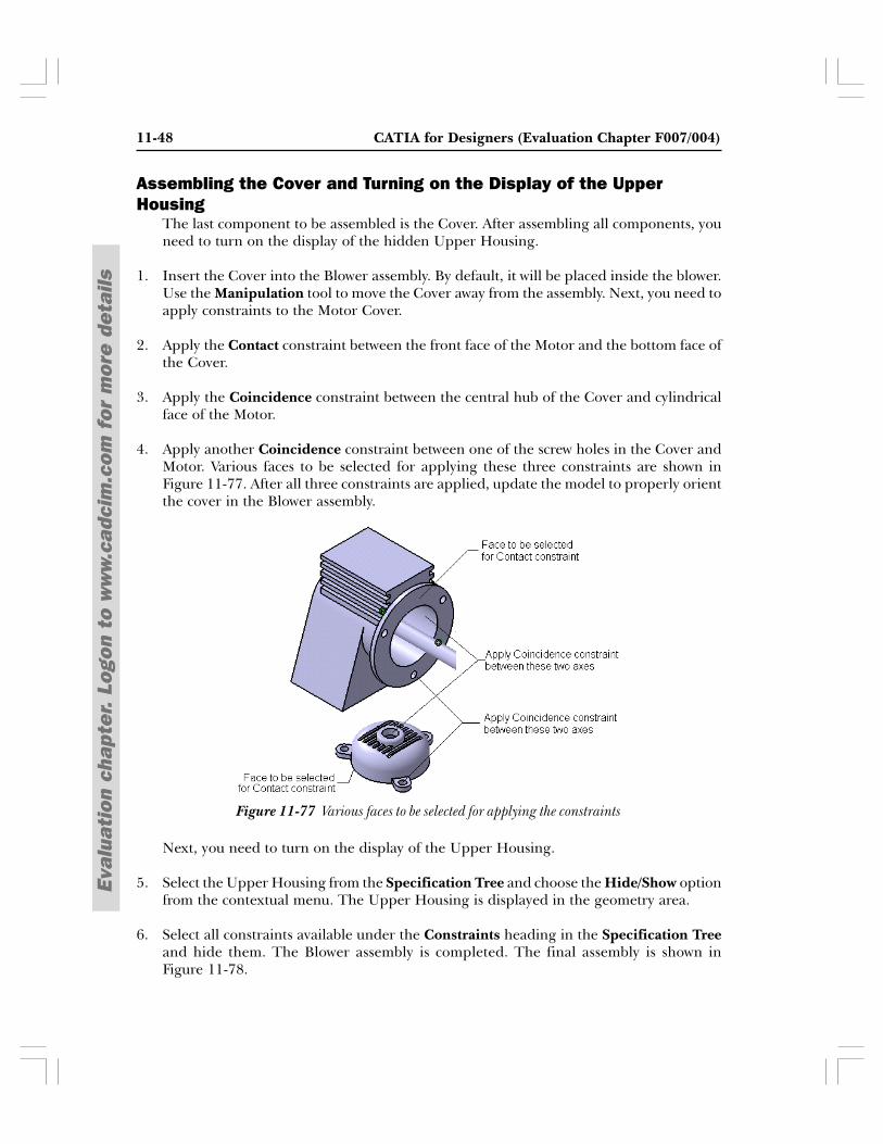
11-48 CATIA for Designers (Evaluation Chapter F007/004)
Eval
uati
on c
hapt
er.
Logo
n to
ww
w.c
adci
m.c
om f
or m
ore
deta
ils
Assembling the Cover and Turning on the Display of the UpperHousing
The last component to be assembled is the Cover. After assembling all components, youneed to turn on the display of the hidden Upper Housing.
1. Insert the Cover into the Blower assembly. By default, it will be placed inside the blower.Use the Manipulation tool to move the Cover away from the assembly. Next, you need toapply constraints to the Motor Cover.
2. Apply the Contact constraint between the front face of the Motor and the bottom face ofthe Cover.
3. Apply the Coincidence constraint between the central hub of the Cover and cylindricalface of the Motor.
4. Apply another Coincidence constraint between one of the screw holes in the Cover andMotor. Various faces to be selected for applying these three constraints are shown inFigure 11-77. After all three constraints are applied, update the model to properly orientthe cover in the Blower assembly.
Next, you need to turn on the display of the Upper Housing.
5. Select the Upper Housing from the Specification Tree and choose the Hide/Show optionfrom the contextual menu. The Upper Housing is displayed in the geometry area.
6. Select all constraints available under the Constraints heading in the Specification Treeand hide them. The Blower assembly is completed. The final assembly is shown inFigure 11-78.
Figure 11-77 Various faces to be selected for applying the constraints
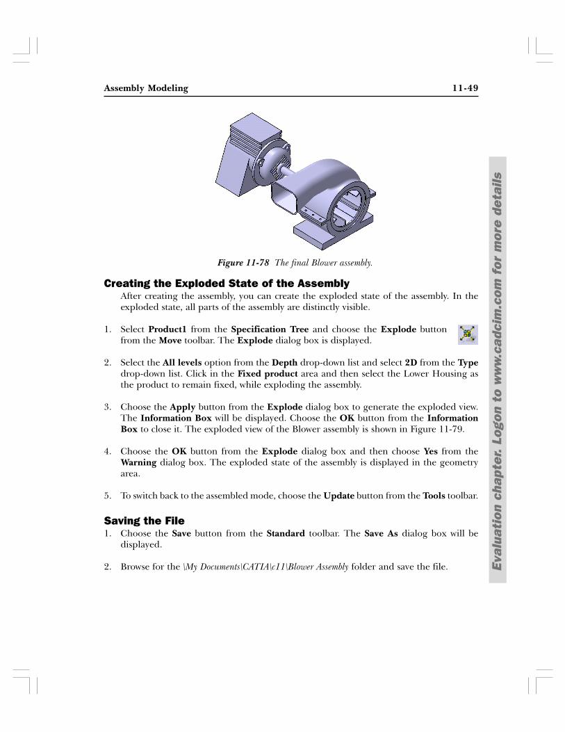
Assembly Modeling 11-49
Eval
uati
on c
hapt
er.
Logo
n to
ww
w.c
adci
m.c
om f
or m
ore
deta
ils
Figure 11-78 The final Blower assembly.
Creating the Exploded State of the AssemblyAfter creating the assembly, you can create the exploded state of the assembly. In theexploded state, all parts of the assembly are distinctly visible.
1. Select Product1 from the Specification Tree and choose the Explode buttonfrom the Move toolbar. The Explode dialog box is displayed.
2. Select the All levels option from the Depth drop-down list and select 2D from the Typedrop-down list. Click in the Fixed product area and then select the Lower Housing asthe product to remain fixed, while exploding the assembly.
3. Choose the Apply button from the Explode dialog box to generate the exploded view.The Information Box will be displayed. Choose the OK button from the InformationBox to close it. The exploded view of the Blower assembly is shown in Figure 11-79.
4. Choose the OK button from the Explode dialog box and then choose Yes from theWarning dialog box. The exploded state of the assembly is displayed in the geometryarea.
5. To switch back to the assembled mode, choose the Update button from the Tools toolbar.
Saving the File1. Choose the Save button from the Standard toolbar. The Save As dialog box will be
displayed.
2. Browse for the \My Documents\CATIA\c11\Blower Assembly folder and save the file.
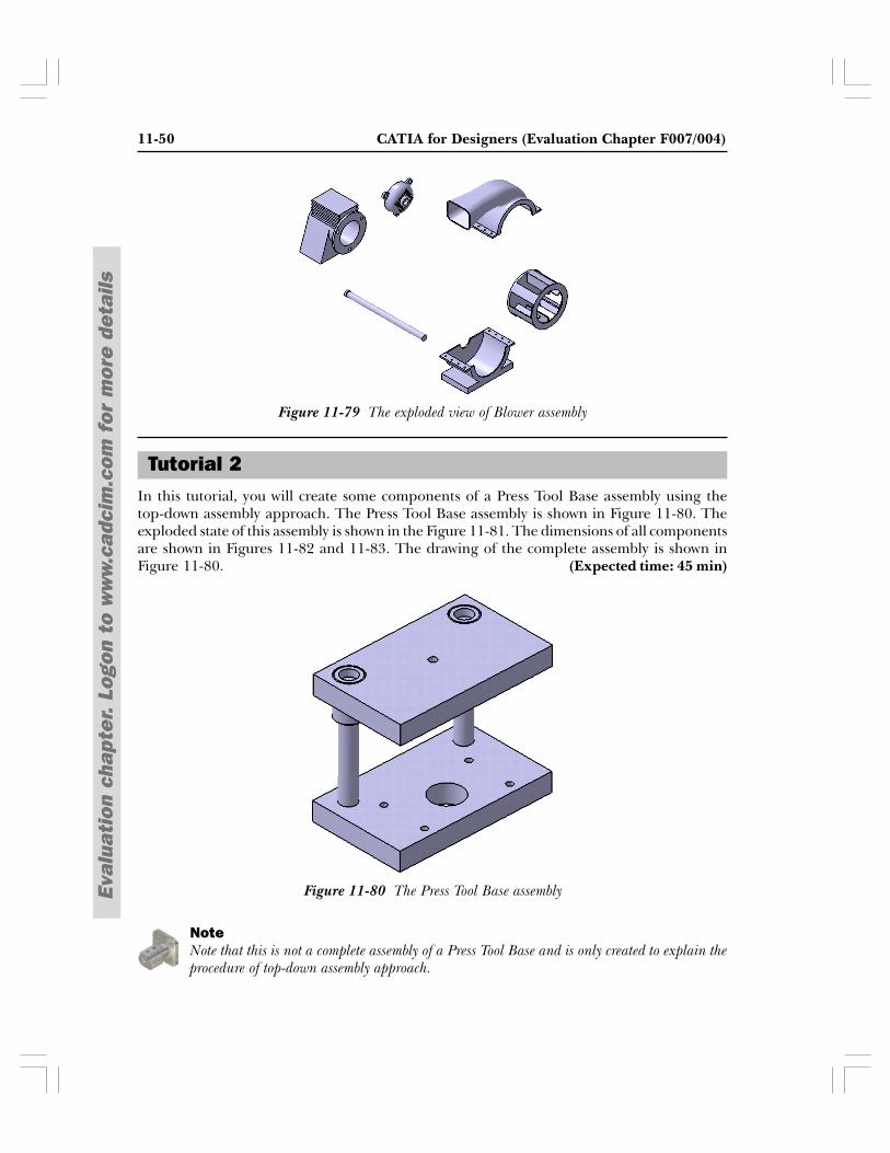
11-50 CATIA for Designers (Evaluation Chapter F007/004)
Eval
uati
on c
hapt
er.
Logo
n to
ww
w.c
adci
m.c
om f
or m
ore
deta
ils
In this tutorial, you will create some components of a Press Tool Base assembly using thetop-down assembly approach. The Press Tool Base assembly is shown in Figure 11-80. Theexploded state of this assembly is shown in the Figure 11-81. The dimensions of all componentsare shown in Figures 11-82 and 11-83. The drawing of the complete assembly is shown inFigure 11-80. (Expected time: 45 min)
NoteNote that this is not a complete assembly of a Press Tool Base and is only created to explain theprocedure of top-down assembly approach.
Figure 11-79 The exploded view of Blower assembly
Tutorial 2
Figure 11-80 The Press Tool Base assembly
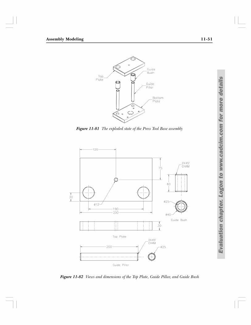
Assembly Modeling 11-51
Eval
uati
on c
hapt
er.
Logo
n to
ww
w.c
adci
m.c
om f
or m
ore
deta
ils
Figure 11-82 Views and dimensions of the Top Plate, Guide Pillar, and Guide Bush
Figure 11-81 The exploded state of the Press Tool Base assembly
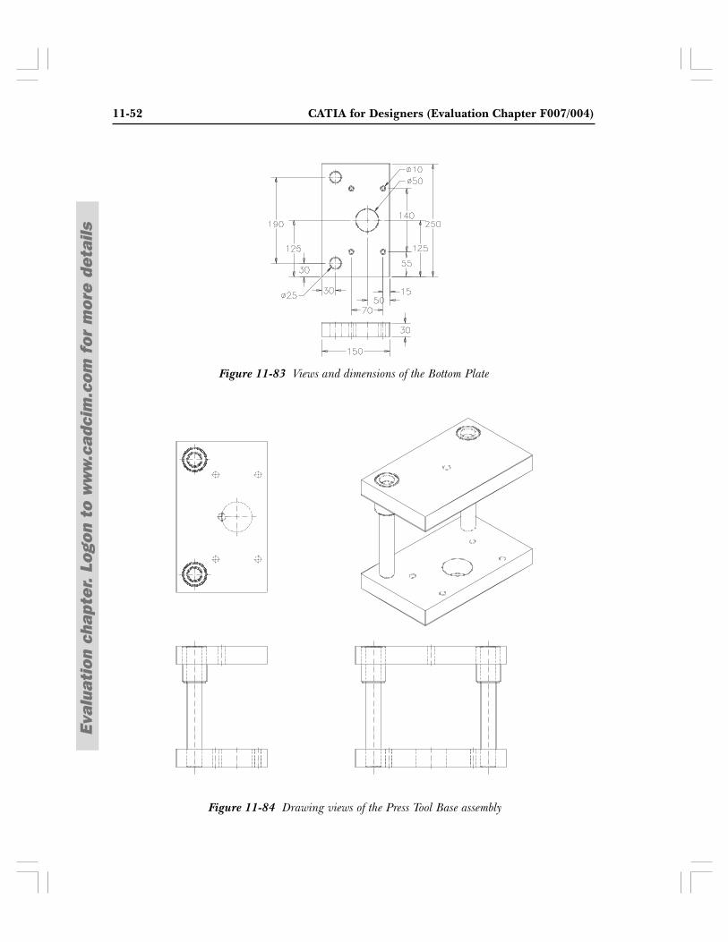
11-52 CATIA for Designers (Evaluation Chapter F007/004)
Eval
uati
on c
hapt
er.
Logo
n to
ww
w.c
adci
m.c
om f
or m
ore
deta
ils
Figure 11-83 Views and dimensions of the Bottom Plate
Figure 11-84 Drawing views of the Press Tool Base assembly
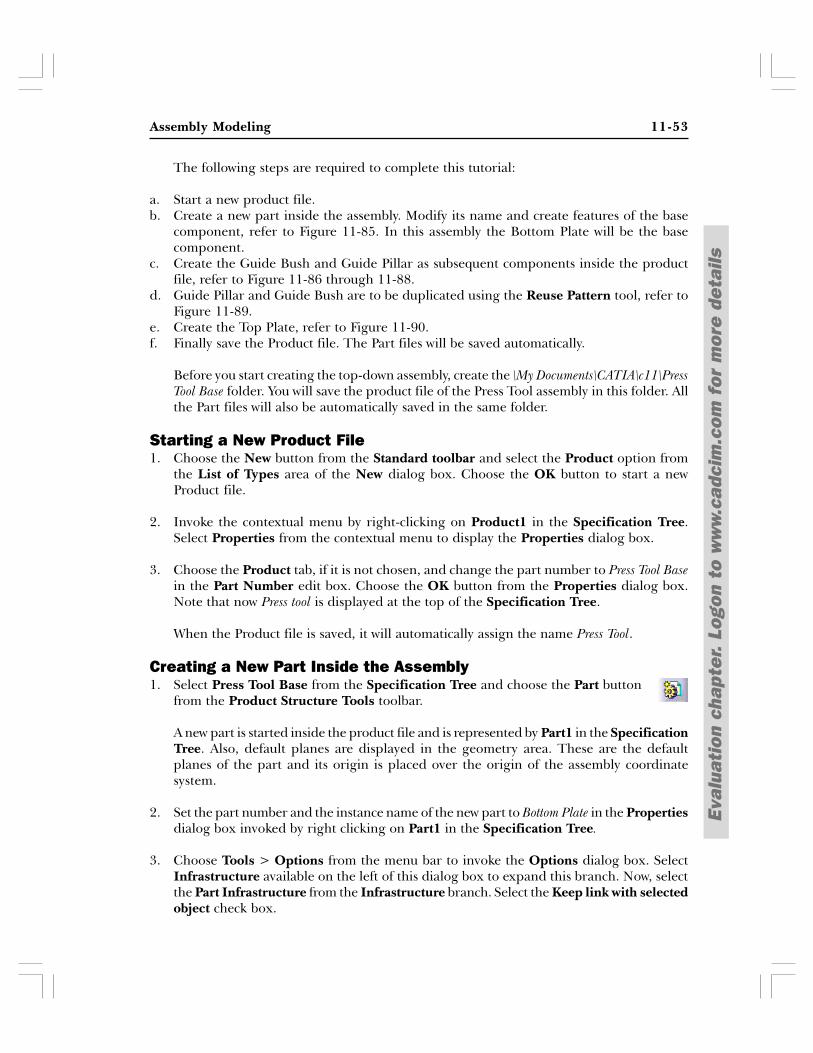
Assembly Modeling 11-53
Eval
uati
on c
hapt
er.
Logo
n to
ww
w.c
adci
m.c
om f
or m
ore
deta
ils
The following steps are required to complete this tutorial:
a. Start a new product file.b. Create a new part inside the assembly. Modify its name and create features of the base
component, refer to Figure 11-85. In this assembly the Bottom Plate will be the basecomponent.
c. Create the Guide Bush and Guide Pillar as subsequent components inside the productfile, refer to Figure 11-86 through 11-88.
d. Guide Pillar and Guide Bush are to be duplicated using the Reuse Pattern tool, refer toFigure 11-89.
e. Create the Top Plate, refer to Figure 11-90.f. Finally save the Product file. The Part files will be saved automatically.
Before you start creating the top-down assembly, create the \My Documents\CATIA\c11\PressTool Base folder. You will save the product file of the Press Tool assembly in this folder. Allthe Part files will also be automatically saved in the same folder.
Starting a New Product File1. Choose the New button from the Standard toolbar and select the Product option from
the List of Types area of the New dialog box. Choose the OK button to start a newProduct file.
2. Invoke the contextual menu by right-clicking on Product1 in the Specification Tree.Select Properties from the contextual menu to display the Properties dialog box.
3. Choose the Product tab, if it is not chosen, and change the part number to Press Tool Basein the Part Number edit box. Choose the OK button from the Properties dialog box.Note that now Press tool is displayed at the top of the Specification Tree.
When the Product file is saved, it will automatically assign the name Press Tool.
Creating a New Part Inside the Assembly1. Select Press Tool Base from the Specification Tree and choose the Part button
from the Product Structure Tools toolbar.
A new part is started inside the product file and is represented by Part1 in the SpecificationTree. Also, default planes are displayed in the geometry area. These are the defaultplanes of the part and its origin is placed over the origin of the assembly coordinatesystem.
2. Set the part number and the instance name of the new part to Bottom Plate in the Propertiesdialog box invoked by right clicking on Part1 in the Specification Tree.
3. Choose Tools > Options from the menu bar to invoke the Options dialog box. SelectInfrastructure available on the left of this dialog box to expand this branch. Now, selectthe Part Infrastructure from the Infrastructure branch. Select the Keep link with selectedobject check box.
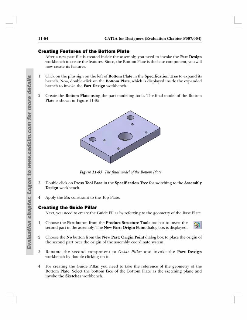
11-54 CATIA for Designers (Evaluation Chapter F007/004)
Eval
uati
on c
hapt
er.
Logo
n to
ww
w.c
adci
m.c
om f
or m
ore
deta
ils
Figure 11-85 The final model of the Bottom Plate
Creating Features of the Bottom PlateAfter a new part file is created inside the assembly, you need to invoke the Part Designworkbench to create the features. Since, the Bottom Plate is the base component, you willnow create its features.
1. Click on the plus sign on the left of Bottom Plate in the Specification Tree to expand itsbranch. Now, double-click on the Bottom Plate, which is displayed inside the expandedbranch to invoke the Part Design workbench.
2. Create the Bottom Plate using the part modeling tools. The final model of the BottomPlate is shown in Figure 11-85.
3. Double click on Press Tool Base in the Specification Tree for switching to the AssemblyDesign workbench.
4. Apply the Fix constraint to the Top Plate.
Creating the Guide PillarNext, you need to create the Guide Pillar by referring to the geometry of the Base Plate.
1. Choose the Part button from the Product Structure Tools toolbar to insert thesecond part in the assembly. The New Part: Origin Point dialog box is displayed.
2. Choose the No button from the New Part: Origin Point dialog box to place the origin ofthe second part over the origin of the assembly coordinate system.
3. Rename the second component to Guide Pillar and invoke the Part Designworkbench by double-clicking on it.
4. For creating the Guide Pillar, you need to take the reference of the geometry of theBottom Plate. Select the bottom face of the Bottom Plate as the sketching plane andinvoke the Sketcher workbench.
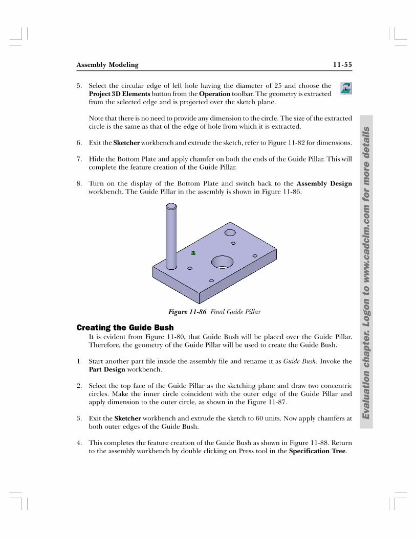
Assembly Modeling 11-55
Eval
uati
on c
hapt
er.
Logo
n to
ww
w.c
adci
m.c
om f
or m
ore
deta
ils
5. Select the circular edge of left hole having the diameter of 25 and choose theProject 3D Elements button from the Operation toolbar. The geometry is extractedfrom the selected edge and is projected over the sketch plane.
Note that there is no need to provide any dimension to the circle. The size of the extractedcircle is the same as that of the edge of hole from which it is extracted.
6. Exit the Sketcher workbench and extrude the sketch, refer to Figure 11-82 for dimensions.
7. Hide the Bottom Plate and apply chamfer on both the ends of the Guide Pillar. This willcomplete the feature creation of the Guide Pillar.
8. Turn on the display of the Bottom Plate and switch back to the Assembly Designworkbench. The Guide Pillar in the assembly is shown in Figure 11-86.
Creating the Guide BushIt is evident from Figure 11-80, that Guide Bush will be placed over the Guide Pillar.Therefore, the geometry of the Guide Pillar will be used to create the Guide Bush.
1. Start another part file inside the assembly file and rename it as Guide Bush. Invoke thePart Design workbench.
2. Select the top face of the Guide Pillar as the sketching plane and draw two concentriccircles. Make the inner circle coincident with the outer edge of the Guide Pillar andapply dimension to the outer circle, as shown in the Figure 11-87.
3. Exit the Sketcher workbench and extrude the sketch to 60 units. Now apply chamfers atboth outer edges of the Guide Bush.
4. This completes the feature creation of the Guide Bush as shown in Figure 11-88. Returnto the assembly workbench by double clicking on Press tool in the Specification Tree.
Figure 11-86 Final Guide Pillar
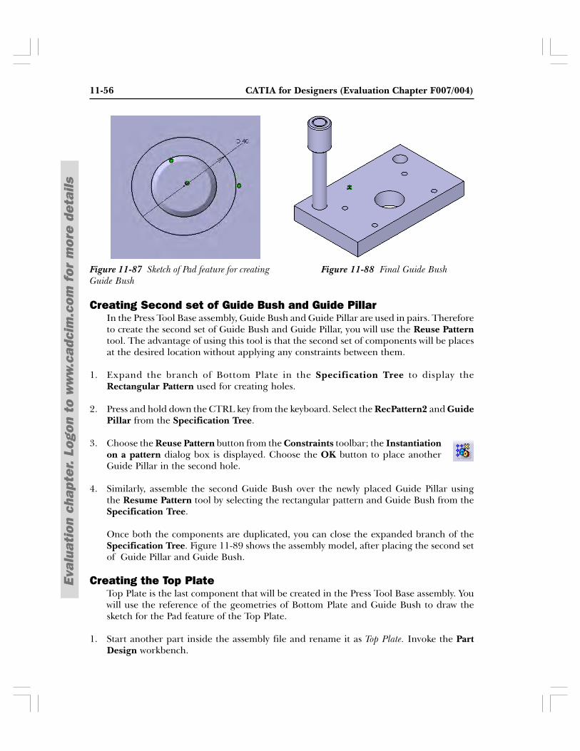
11-56 CATIA for Designers (Evaluation Chapter F007/004)
Eval
uati
on c
hapt
er.
Logo
n to
ww
w.c
adci
m.c
om f
or m
ore
deta
ils
Figure 11-88 Final Guide BushFigure 11-87 Sketch of Pad feature for creatingGuide Bush
Creating Second set of Guide Bush and Guide PillarIn the Press Tool Base assembly, Guide Bush and Guide Pillar are used in pairs. Thereforeto create the second set of Guide Bush and Guide Pillar, you will use the Reuse Patterntool. The advantage of using this tool is that the second set of components will be placesat the desired location without applying any constraints between them.
1. Expand the branch of Bottom Plate in the Specification Tree to display theRectangular Pattern used for creating holes.
2. Press and hold down the CTRL key from the keyboard. Select the RecPattern2 and GuidePillar from the Specification Tree.
3. Choose the Reuse Pattern button from the Constraints toolbar; the Instantiationon a pattern dialog box is displayed. Choose the OK button to place anotherGuide Pillar in the second hole.
4. Similarly, assemble the second Guide Bush over the newly placed Guide Pillar usingthe Resume Pattern tool by selecting the rectangular pattern and Guide Bush from theSpecification Tree.
Once both the components are duplicated, you can close the expanded branch of theSpecification Tree. Figure 11-89 shows the assembly model, after placing the second setof Guide Pillar and Guide Bush.
Creating the Top PlateTop Plate is the last component that will be created in the Press Tool Base assembly. Youwill use the reference of the geometries of Bottom Plate and Guide Bush to draw thesketch for the Pad feature of the Top Plate.
1. Start another part inside the assembly file and rename it as Top Plate. Invoke the PartDesign workbench.
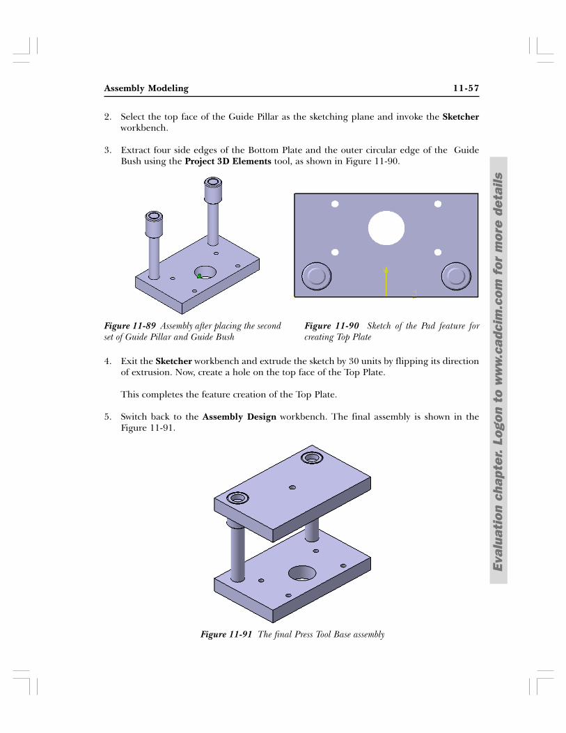
Assembly Modeling 11-57
Eval
uati
on c
hapt
er.
Logo
n to
ww
w.c
adci
m.c
om f
or m
ore
deta
ils
2. Select the top face of the Guide Pillar as the sketching plane and invoke the Sketcherworkbench.
3. Extract four side edges of the Bottom Plate and the outer circular edge of the GuideBush using the Project 3D Elements tool, as shown in Figure 11-90.
4. Exit the Sketcher workbench and extrude the sketch by 30 units by flipping its directionof extrusion. Now, create a hole on the top face of the Top Plate.
This completes the feature creation of the Top Plate.
5. Switch back to the Assembly Design workbench. The final assembly is shown in theFigure 11-91.
Figure 11-89 Assembly after placing the secondset of Guide Pillar and Guide Bush
Figure 11-90 Sketch of the Pad feature forcreating Top Plate
Figure 11-91 The final Press Tool Base assembly
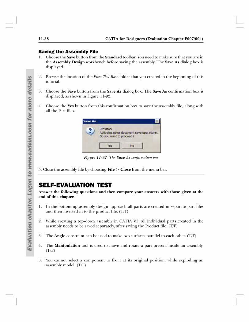
11-58 CATIA for Designers (Evaluation Chapter F007/004)
Eval
uati
on c
hapt
er.
Logo
n to
ww
w.c
adci
m.c
om f
or m
ore
deta
ils
Figure 11-92 The Save As confirmation box
Saving the Assembly File1. Choose the Save button from the Standard toolbar. You need to make sure that you are in
the Assembly Design workbench before saving the assembly. The Save As dialog box isdisplayed.
2. Browse the location of the Press Tool Base folder that you created in the beginning of thistutorial.
3. Choose the Save button from the Save As dialog box. The Save As confirmation box isdisplayed, as shown in Figure 11-92.
4. Choose the Yes button from this confirmation box to save the assembly file, along withall the Part files.
5. Close the assembly file by choosing File > Close from the menu bar.
SELF-EVALUATION TESTAnswer the following questions and then compare your answers with those given at theend of this chapter.
1. In the bottom-up assembly design approach all parts are created in separate part filesand then inserted in to the product file. (T/F)
2. While creating a top-down assembly in CATIA V5, all individual parts created in theassembly needs to be saved separately, after saving the Product file. (T/F)
3. The Angle constraint can be used to make two surfaces parallel to each other. (T/F)
4. The Manipulation tool is used to move and rotate a part present inside an assembly.(T/F)
5. You cannot select a component to fix it at its original position, while exploding anassembly model. (T/F)
Assembly Modeling 11-59
Eval
uati
on c
hapt
er.
Logo
n to
ww
w.c
adci
m.c
om f
or m
ore
deta
ils
6. The __________constraint is used to place two planar faces at a specified angle withrespect to each other.
7. You can place multiple instances of a component over a predefined pattern by using the__________tool.
8. The __________option is selected from the Type drop-down list in the Explode dialogbox to explode all components of assembly along the 2D plane, which is currently parallelto screen.
9. The edges of a component can be snapped on to an edge of another component by usingthe __________ tool.
10. If two parts having the same name are inserted into the assembly file then __________dialog box is displayed.
REVIEW QUESTIONSAnswer the following questions.
1. The __________ constraint is used to make two cylindrical surfaces concentric.
2. Select the component and then choose the __________ button to hide it from the geometryarea.
3. The __________ tool can be used to move a component and also apply a constraint to it.
4. The cross-section of an assembly model can be viewed using the __________ tool.
5. An existing part can be inserted into a Product file using the _________ button.
6. Which tool is used to calculate the interference between two mating components?
(a) Measure (b) Clash(c) Smart Move (d) Snap
7. Which button is used to replace a constraint by another constraint?
(a) Reuse Pattern (b) Replace Component(c) Change Constraint (d) Replace Constraint
8. Which button is used to apply the most appropriate constraint to the current selectionset?
(a) Quick Constraint (b) Change Constraint(c) Contact Constraint (d) None of these
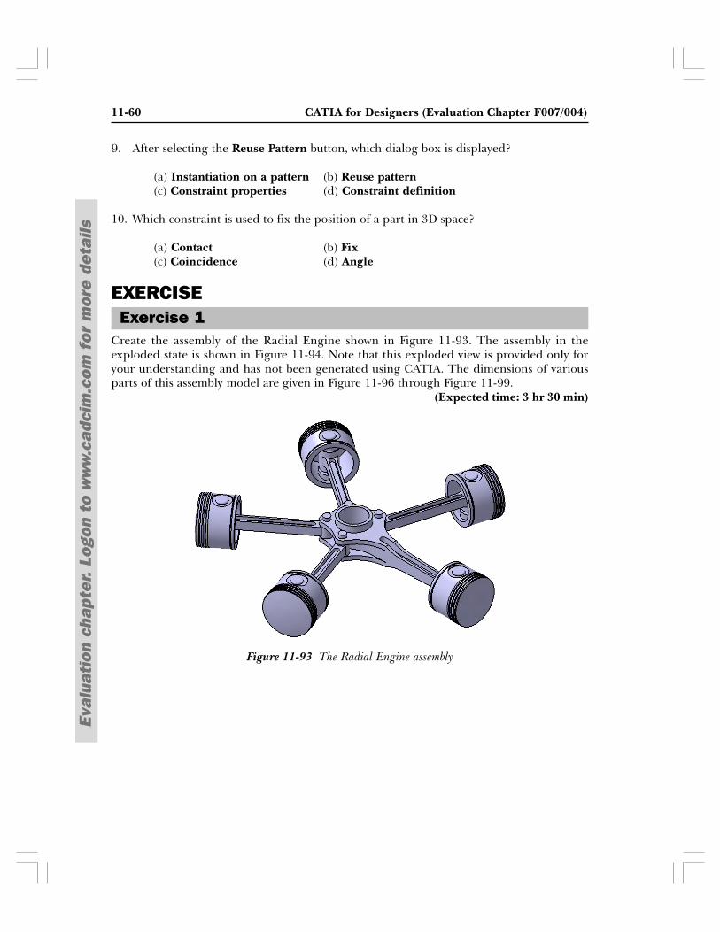
11-60 CATIA for Designers (Evaluation Chapter F007/004)
Eval
uati
on c
hapt
er.
Logo
n to
ww
w.c
adci
m.c
om f
or m
ore
deta
ils
Figure 11-93 The Radial Engine assembly
Exercise 1
9. After selecting the Reuse Pattern button, which dialog box is displayed?
(a) Instantiation on a pattern (b) Reuse pattern(c) Constraint properties (d) Constraint definition
10. Which constraint is used to fix the position of a part in 3D space?
(a) Contact (b) Fix(c) Coincidence (d) Angle
EXERCISE
Create the assembly of the Radial Engine shown in Figure 11-93. The assembly in theexploded state is shown in Figure 11-94. Note that this exploded view is provided only foryour understanding and has not been generated using CATIA. The dimensions of variousparts of this assembly model are given in Figure 11-96 through Figure 11-99.
(Expected time: 3 hr 30 min)
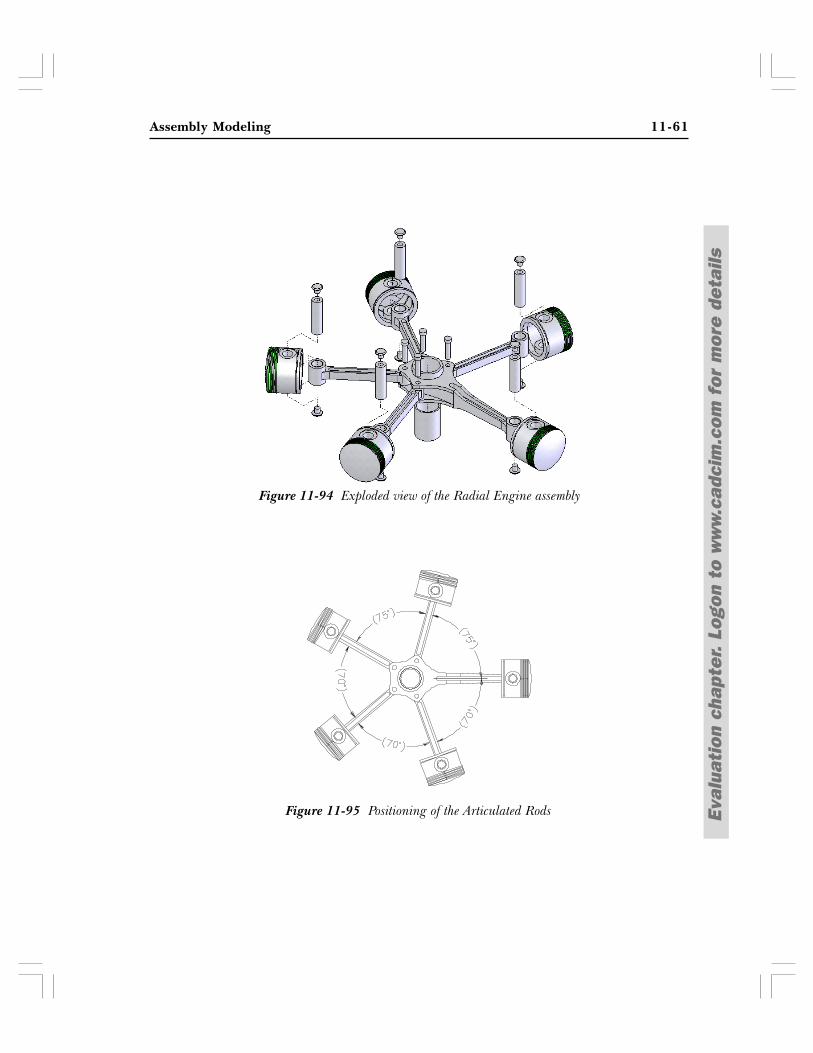
Assembly Modeling 11-61
Eval
uati
on c
hapt
er.
Logo
n to
ww
w.c
adci
m.c
om f
or m
ore
deta
ils
Figure 11-94 Exploded view of the Radial Engine assembly
Figure 11-95 Positioning of the Articulated Rods
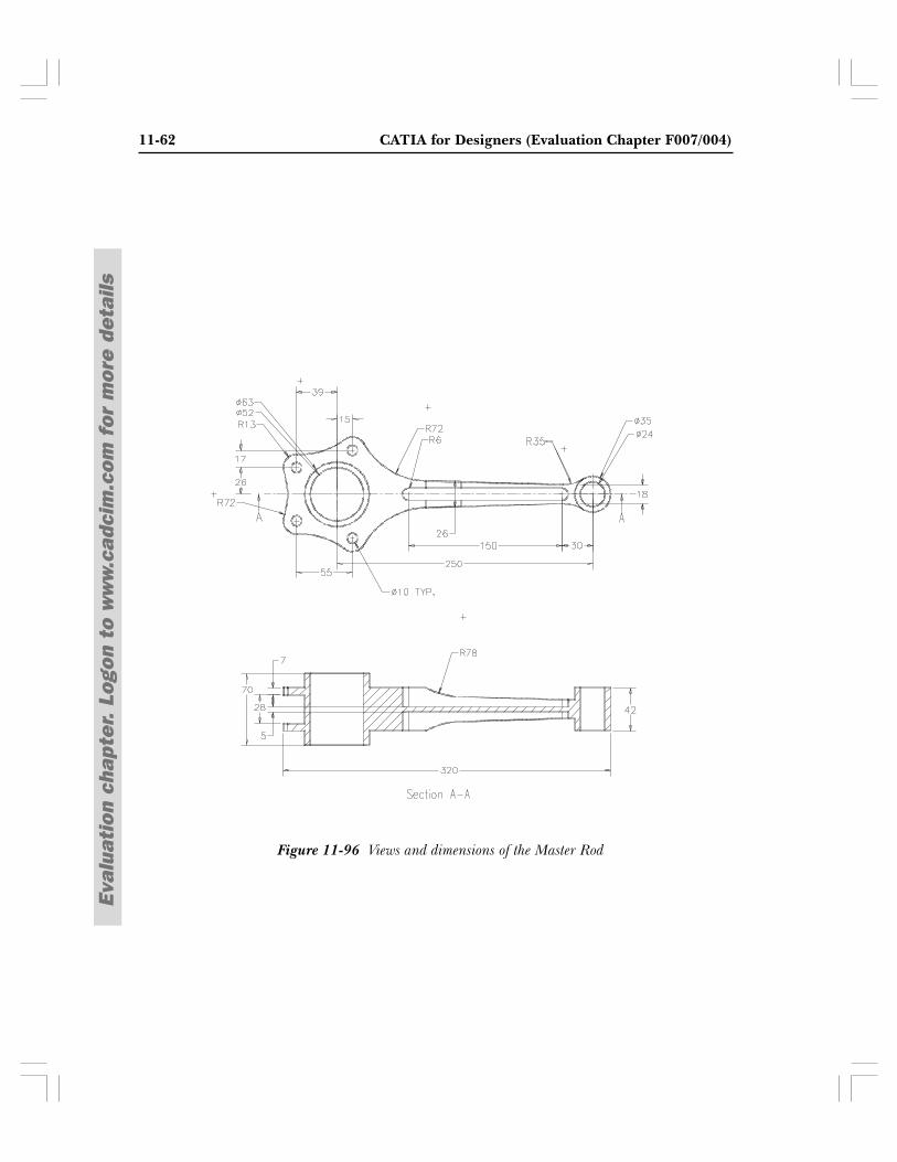
11-62 CATIA for Designers (Evaluation Chapter F007/004)
Eval
uati
on c
hapt
er.
Logo
n to
ww
w.c
adci
m.c
om f
or m
ore
deta
ils
Figure 11-96 Views and dimensions of the Master Rod
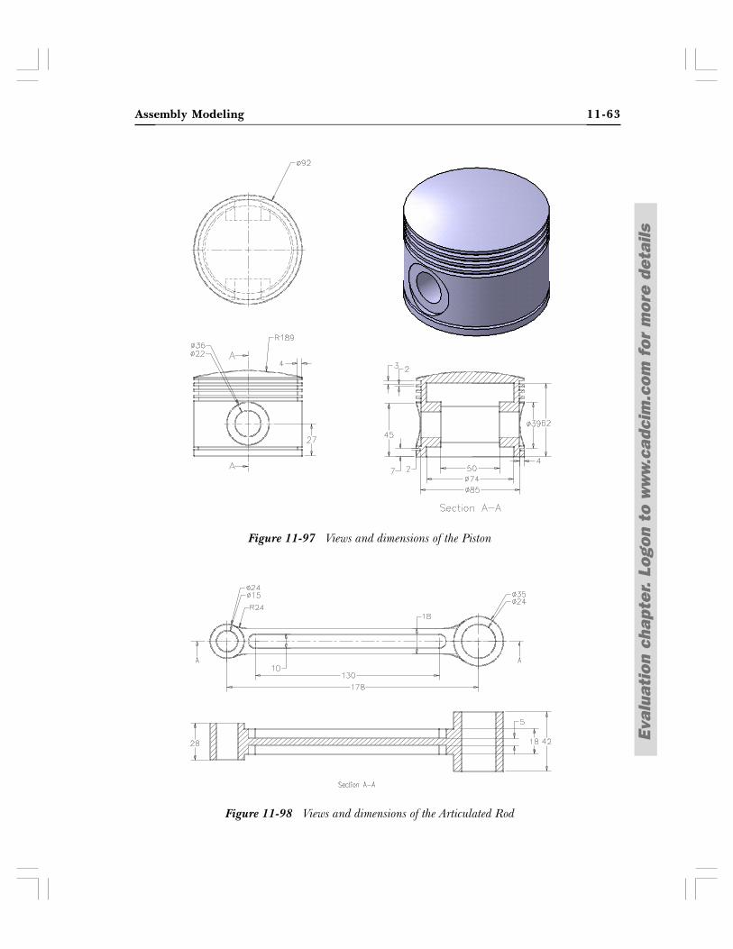
Assembly Modeling 11-63
Eval
uati
on c
hapt
er.
Logo
n to
ww
w.c
adci
m.c
om f
or m
ore
deta
ils
Figure 11-97 Views and dimensions of the Piston
Figure 11-98 Views and dimensions of the Articulated Rod
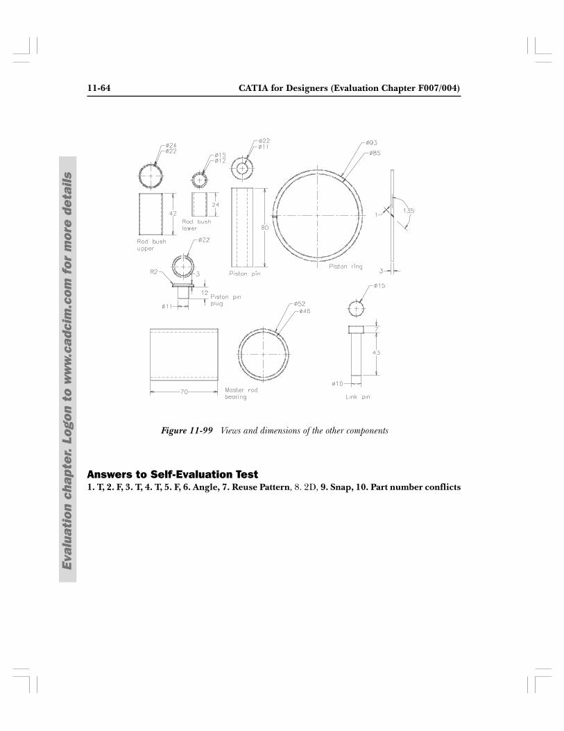
11-64 CATIA for Designers (Evaluation Chapter F007/004)
Eval
uati
on c
hapt
er.
Logo
n to
ww
w.c
adci
m.c
om f
or m
ore
deta
ils
Figure 11-99 Views and dimensions of the other components
Answers to Self-Evaluation Test1. T, 2. F, 3. T, 4. T, 5. F, 6. Angle, 7. Reuse Pattern, 8. 2D, 9. Snap, 10. Part number conflicts