Embed Size (px)
Citation preview

ACS 800
Hardware ManualACS800-17 Drives (75 to 1120 kW)


ACS800-17 Drives (75 to 1120 kW)
Hardware Manual
3AFE 64681338 Rev AEN
EFFECTIVE: 01.11.2002
2002 ABB Oy. All Rights Reserved.


5
Safety instructions
OverviewThis chapter states the safety instructions that must be followed when installing, operating and servicing ACS800-17 frequency converters. If neglected, physical injury and death may follow, or damage may occur to the frequency converter, the motor and driven equipment. The material in this chapter and the IGBT Supply Unit specific instructions (given in the ISU Section Users Manual) must be studied before attempting any work on, or with, the unit.
The following notation is used throughout the manual:
Note: Gives additional information or points out more information available on the subject.
Installation and maintenance safetyThese safety instructions are intended for all work on the drive. Neglecting these instructions can cause physical injury or death.
WARNING! All electrical installation and maintenance work on the drive should be carried out by qualified electricians.
Any installation work must be done with the power off, and power is not to be reconnected unless the installation work is complete. Dangerous residual voltages remain in capacitors when the disconnecting device is opened. Wait 5 minutes after switching off the supply before starting work. Always ensure by measuring that the voltage between terminals UDC+ and UDC- and frame is close to 0 V and that the supply has been switched off before performing any work on the equipment or making main circuit connections.
If the main circuit of the inverter unit is live, the motor terminals are also live even if the motor is not running!
When joining shipping splits, check the cable connections at the shipping split joints
Dangerous Voltage WARNING! warns of situations in which a high voltage can cause physical injury and/or damage equipment. The text next to this symbol describes ways to avoid the danger.
General WARNING! warns of situations which can cause physical injury and/or damage equipment by means other than electrical. The text next to this symbol describes ways to avoid the danger.
Electrostatic Discharge WARNING! warns of situations in which an electrostatic discharge can damage equipment. The text next to this symbol describes ways to avoid the danger.
Safety instructions

6
before switching on the supply voltage.
If the auxiliary voltage circuit of the drive is powered from an external power supply, opening the disconnecting device does not remove all voltages. Control voltages of 115/230 VAC may be present on the digital inputs or outputs even though the inverter unit is not powered. Before starting work, check which circuits remain live after opening of the disconnecting device by referring to the circuit diagrams for your particular delivery. Ensure by measuring that the part of the cabinet you are working on is not live.
In frequency converters, control boards of the converter unit may be at the main circuit potential. Dangerous voltages may be present between the control boards and the frame of the converter unit, when the main circuit voltage is on. It is critical that the measuring instruments, such as an oscilloscope, are used with caution and safety always as a priority. The fault tracing instructions give special mention of cases in which measurements may be performed on the control boards, also indicating the measuring method to be used.
Live parts on the inside of doors are protected against direct contact. Special safety attention shall be paid when handling shrouds made of sheet metal.
Do not make any voltage withstand tests on any part of the unit while the unit is connected. Disconnect motor cables before making any measurements on motors or motor cables.
WARNING! Do not use the Prevention of Unexpected Start for stopping the drive when the inverter is running. Give a Stop command instead.
WARNING! Fans may continue to rotate for a while after the disconnection of the electrical supply.
WARNING! Some parts like heatsinks of power semiconductors and toroidal cores on motor cables inside the cabinet remain hot for a while after the disconnection of the electrical supply.
Safety instructions

7
Permanent magnet motor
WARNING!
Installation and maintenance work
When a permanent magnet motor is connected to the drive, ensure that the driven machine cannot rotate the motor during installation and maintenance work. When rotating, the permanent magnet motor feeds power to the intermediate circuit of the drive and also the supply connections become live (even when the inverter is stopped!). Disconnect the motor from the drive with a safety switch, or lock the motor shaft and earth the motor connection terminals temporarily by connecting them together as well as to the PE.
Normal use
Ensure that the permanent magnet motor cannot rotate at too high a speed. Overspeed leads to overvoltage which may explode the capacitors in the intermediate circuit of the drive.
Permanent magnet motor may be used with ACS 800 Permanent Magnet Synchronous Motor Drive Application Program, or with other application programs in scalar control mode only.
Supply connectionsThe supply section is equipped with a disconnecting device. The electric parts of the whole drive system can be separated by the disconnecting device from the mains network for installation and maintenance work. The supply disconnecting device must be locked to the open position during installation and maintenance work. Both disconnecting devices of 12-pulse units must be locked to the open position during installation and maintenance work.
The supply section can be equipped with an earthing switch as an option. It is used to earth the AC busbars for safety reasons when work is being done on the system. The device is mechanically or electrically interlocked with the main switch.
WARNING! Opening the disconnecting device does not remove all control voltages. Before starting work, check with the circuit diagrams which circuits remain live after opening the disconnecting device. Note: Voltages from external control circuits may be present.
The motor must not be controlled with the supply disconnecting device; instead, the and keys of the Control Panel or commands via the digital inputs or serial
communication of the drive should be used. The maximum number of charging cycles of the d.c. capacitors of the drive (i.e. power-ups by applying the mains power) is five in ten minutes.
Safety instructions

8
WARNING! The drive introduces electric motors, drive train mechanisms and driven machines to an extended operating range. It should be determined from the outset that all equipment are up to these conditions.
WARNING! There are several automatic reset functions in the drive (with Standard Application Program). If selected, they reset the unit and resume operation after a fault. These functions should not be selected if other equipment is not compatible with this kind of operation, or dangerous situations can be caused by such action.
WARNING! If an external source for start command is selected and it is ON, the drive (with Standard Application Program) will start immediately after fault reset or power switch on.
WARNING! The printed circuit boards contain integrated circuits that are extremely sensitive to electrostatic discharge. Exercise appropriate care when working on the unit to avoid permanent damage to the circuits. Do not touch the boards unnecessarily.
Fibre optic cables
WARNING! Handle the fibre optic cables with care (especially when joining the shipping splits). When unplugging optic cables, always grab the connector, not the cable itself. Do not touch the ends of the fibres with bare hands as the fibre is extremely sensitive to dirt.
Safety instructions

9
Cooling
WARNING! The cooling air flow and space requirements must be fulfilled.
If the drive is equipped with a double roof, ensure that the roof is lifted up from the transportation position to enable the cooling air flow before starting the drive.
Air flow from below (from a cable conduit) to the cabinet must be prevented to ensure the degree of protection and fire protection.
Mechanical installationWARNING! Fastening any device to the cabinet frame for lifting purposes is forbidden.
WARNING! Make sure that dust from drilling does not enter the cabinet when installing. Electrically conductive dust inside the unit may cause damage or lead to malfunction.
WARNING! Welding of the cabinet frame is not recommended. However, if electric welding is the only way to mount the cabinet, connect the return conductor of the welding equipment low to the cabinet frame within 0.5 metres of the welding point. If the welding return wire is connected improperly, the welding circuit may damage electronic circuits located in the cabinets.
1 2
Safety instructions

10
Safety instructions

11
Table of contents
Safety instructions
Overview . . . . . . . . . . . . . . . . . . . . . . . . . . . . . . . . . . . . . . . . . . . . . . . . . . . . . . . . . . . . . . . . . . . . . . 5Installation and maintenance safety . . . . . . . . . . . . . . . . . . . . . . . . . . . . . . . . . . . . . . . . . . . . . . . . . 5Permanent magnet motor . . . . . . . . . . . . . . . . . . . . . . . . . . . . . . . . . . . . . . . . . . . . . . . . . . . . . . . . . 7Supply connections . . . . . . . . . . . . . . . . . . . . . . . . . . . . . . . . . . . . . . . . . . . . . . . . . . . . . . . . . . . . . . 7Fibre optic cables . . . . . . . . . . . . . . . . . . . . . . . . . . . . . . . . . . . . . . . . . . . . . . . . . . . . . . . . . . . . . . . 8Cooling . . . . . . . . . . . . . . . . . . . . . . . . . . . . . . . . . . . . . . . . . . . . . . . . . . . . . . . . . . . . . . . . . . . . . . . 9Mechanical installation . . . . . . . . . . . . . . . . . . . . . . . . . . . . . . . . . . . . . . . . . . . . . . . . . . . . . . . . . . . 9
Table of contents
Introduction
Overview of the manual . . . . . . . . . . . . . . . . . . . . . . . . . . . . . . . . . . . . . . . . . . . . . . . . . . . . . . . . . . 17Other manuals . . . . . . . . . . . . . . . . . . . . . . . . . . . . . . . . . . . . . . . . . . . . . . . . . . . . . . . . . . . . . . . . . 17Delivery check . . . . . . . . . . . . . . . . . . . . . . . . . . . . . . . . . . . . . . . . . . . . . . . . . . . . . . . . . . . . . . . . . 17Inquiries . . . . . . . . . . . . . . . . . . . . . . . . . . . . . . . . . . . . . . . . . . . . . . . . . . . . . . . . . . . . . . . . . . . . . . 18
Hardware description
Chapter overview . . . . . . . . . . . . . . . . . . . . . . . . . . . . . . . . . . . . . . . . . . . . . . . . . . . . . . . . . . . . . . 19Main components of the ACS800-17 . . . . . . . . . . . . . . . . . . . . . . . . . . . . . . . . . . . . . . . . . . . . . . . 19
Frame sizes R6i to R9i . . . . . . . . . . . . . . . . . . . . . . . . . . . . . . . . . . . . . . . . . . . . . . . . . . . . . . . . 19Frame sizes R11i and R12i . . . . . . . . . . . . . . . . . . . . . . . . . . . . . . . . . . . . . . . . . . . . . . . . . . . . 19
Auxiliary control unit . . . . . . . . . . . . . . . . . . . . . . . . . . . . . . . . . . . . . . . . . . . . . . . . . . . . . . . . . . . . 20Drive section . . . . . . . . . . . . . . . . . . . . . . . . . . . . . . . . . . . . . . . . . . . . . . . . . . . . . . . . . . . . . . . . . . 20
Example . . . . . . . . . . . . . . . . . . . . . . . . . . . . . . . . . . . . . . . . . . . . . . . . . . . . . . . . . . . . . . . . . . . 21Inverter . . . . . . . . . . . . . . . . . . . . . . . . . . . . . . . . . . . . . . . . . . . . . . . . . . . . . . . . . . . . . . . . . . . . . . 21
Control boards . . . . . . . . . . . . . . . . . . . . . . . . . . . . . . . . . . . . . . . . . . . . . . . . . . . . . . . . . . . . . . 21Power plate . . . . . . . . . . . . . . . . . . . . . . . . . . . . . . . . . . . . . . . . . . . . . . . . . . . . . . . . . . . . . . . . . 24Main circuit diagram . . . . . . . . . . . . . . . . . . . . . . . . . . . . . . . . . . . . . . . . . . . . . . . . . . . . . . . . . . 24
Voltages from the supply section . . . . . . . . . . . . . . . . . . . . . . . . . . . . . . . . . . . . . . . . . . . . . . . . . . 26Use of extra RDIO with frame size R12i . . . . . . . . . . . . . . . . . . . . . . . . . . . . . . . . . . . . . . . . . . . . . 26
Mechanical installation
Chapter overview . . . . . . . . . . . . . . . . . . . . . . . . . . . . . . . . . . . . . . . . . . . . . . . . . . . . . . . . . . . . . . 27General . . . . . . . . . . . . . . . . . . . . . . . . . . . . . . . . . . . . . . . . . . . . . . . . . . . . . . . . . . . . . . . . . . . . . . 27Required tools . . . . . . . . . . . . . . . . . . . . . . . . . . . . . . . . . . . . . . . . . . . . . . . . . . . . . . . . . . . . . . . . . 27Cabinet construction . . . . . . . . . . . . . . . . . . . . . . . . . . . . . . . . . . . . . . . . . . . . . . . . . . . . . . . . . . . . 28Moving of the shipping split . . . . . . . . . . . . . . . . . . . . . . . . . . . . . . . . . . . . . . . . . . . . . . . . . . . . . . . 29
by crane . . . . . . . . . . . . . . . . . . . . . . . . . . . . . . . . . . . . . . . . . . . . . . . . . . . . . . . . . . . . . . . . . . . 29by fork-lift . . . . . . . . . . . . . . . . . . . . . . . . . . . . . . . . . . . . . . . . . . . . . . . . . . . . . . . . . . . . . . . . . . 30
Table of contents

12
by split rollers . . . . . . . . . . . . . . . . . . . . . . . . . . . . . . . . . . . . . . . . . . . . . . . . . . . . . . . . . . . . . . . 30Final placement of the shipping splits . . . . . . . . . . . . . . . . . . . . . . . . . . . . . . . . . . . . . . . . . . . . 31
Removing the lifting lugs and bars . . . . . . . . . . . . . . . . . . . . . . . . . . . . . . . . . . . . . . . . . . . . . . . . . 31Working order of the mechanical installation . . . . . . . . . . . . . . . . . . . . . . . . . . . . . . . . . . . . . . . . . 32Fastening the shipping split to the floor (Non-marine units) . . . . . . . . . . . . . . . . . . . . . . . . . . . . . . 33
Fastening clamps . . . . . . . . . . . . . . . . . . . . . . . . . . . . . . . . . . . . . . . . . . . . . . . . . . . . . . . . . . . . 33Holes inside the cabinet . . . . . . . . . . . . . . . . . . . . . . . . . . . . . . . . . . . . . . . . . . . . . . . . . . . . . . . 34
Fastening the shipping splits to the floor and wall (Marine units) . . . . . . . . . . . . . . . . . . . . . . . . . . 35Joining the shipping splits . . . . . . . . . . . . . . . . . . . . . . . . . . . . . . . . . . . . . . . . . . . . . . . . . . . . . . . 36
Working order . . . . . . . . . . . . . . . . . . . . . . . . . . . . . . . . . . . . . . . . . . . . . . . . . . . . . . . . . . . . . . 36Connecting the DC busbar and the PE busbar . . . . . . . . . . . . . . . . . . . . . . . . . . . . . . . . . . . . . 37
Lifting a double roof . . . . . . . . . . . . . . . . . . . . . . . . . . . . . . . . . . . . . . . . . . . . . . . . . . . . . . . . . . . . 39Miscellaneous . . . . . . . . . . . . . . . . . . . . . . . . . . . . . . . . . . . . . . . . . . . . . . . . . . . . . . . . . . . . . . . . . 40
Cable conduit in the floor below the cabinet . . . . . . . . . . . . . . . . . . . . . . . . . . . . . . . . . . . . . . . 40Electric welding . . . . . . . . . . . . . . . . . . . . . . . . . . . . . . . . . . . . . . . . . . . . . . . . . . . . . . . . . . . . . 41
Electrical installation planning
Chapter overview . . . . . . . . . . . . . . . . . . . . . . . . . . . . . . . . . . . . . . . . . . . . . . . . . . . . . . . . . . . . . . 43Supply . . . . . . . . . . . . . . . . . . . . . . . . . . . . . . . . . . . . . . . . . . . . . . . . . . . . . . . . . . . . . . . . . . . . . . 43
Earth fault protective function . . . . . . . . . . . . . . . . . . . . . . . . . . . . . . . . . . . . . . . . . . . . . . . . . . 44Fuses . . . . . . . . . . . . . . . . . . . . . . . . . . . . . . . . . . . . . . . . . . . . . . . . . . . . . . . . . . . . . . . . . . . . . . . 44
Internal fuses . . . . . . . . . . . . . . . . . . . . . . . . . . . . . . . . . . . . . . . . . . . . . . . . . . . . . . . . . . . . . . . 44Motor and output filter selection . . . . . . . . . . . . . . . . . . . . . . . . . . . . . . . . . . . . . . . . . . . . . . . . . . . 45
Pulses in the drive output . . . . . . . . . . . . . . . . . . . . . . . . . . . . . . . . . . . . . . . . . . . . . . . . . . . . . 45Protecting the motor winding . . . . . . . . . . . . . . . . . . . . . . . . . . . . . . . . . . . . . . . . . . . . . . . . . . . 45Protecting the motor bearings . . . . . . . . . . . . . . . . . . . . . . . . . . . . . . . . . . . . . . . . . . . . . . . . . . 45Requirements table . . . . . . . . . . . . . . . . . . . . . . . . . . . . . . . . . . . . . . . . . . . . . . . . . . . . . . . . . . 45
Power cable selection . . . . . . . . . . . . . . . . . . . . . . . . . . . . . . . . . . . . . . . . . . . . . . . . . . . . . . . . . . 49Alternatives . . . . . . . . . . . . . . . . . . . . . . . . . . . . . . . . . . . . . . . . . . . . . . . . . . . . . . . . . . . . . . . . 50Motor cable shield . . . . . . . . . . . . . . . . . . . . . . . . . . . . . . . . . . . . . . . . . . . . . . . . . . . . . . . . . . . 50
Control cable selection . . . . . . . . . . . . . . . . . . . . . . . . . . . . . . . . . . . . . . . . . . . . . . . . . . . . . . . . . . 51Co-axial cable . . . . . . . . . . . . . . . . . . . . . . . . . . . . . . . . . . . . . . . . . . . . . . . . . . . . . . . . . . . . . . 51Optical cable . . . . . . . . . . . . . . . . . . . . . . . . . . . . . . . . . . . . . . . . . . . . . . . . . . . . . . . . . . . . . . . 51Relay cable . . . . . . . . . . . . . . . . . . . . . . . . . . . . . . . . . . . . . . . . . . . . . . . . . . . . . . . . . . . . . . . . 52Control panel cable . . . . . . . . . . . . . . . . . . . . . . . . . . . . . . . . . . . . . . . . . . . . . . . . . . . . . . . . . . 52
Emergency stop devices . . . . . . . . . . . . . . . . . . . . . . . . . . . . . . . . . . . . . . . . . . . . . . . . . . . . . . . . 52Immediate removal of power (Category 0) . . . . . . . . . . . . . . . . . . . . . . . . . . . . . . . . . . . . . . . . 52Controlled emergency stop (Category 1) . . . . . . . . . . . . . . . . . . . . . . . . . . . . . . . . . . . . . . . . . . 52Restart . . . . . . . . . . . . . . . . . . . . . . . . . . . . . . . . . . . . . . . . . . . . . . . . . . . . . . . . . . . . . . . . . . . . 52
Prevention of unexpected start . . . . . . . . . . . . . . . . . . . . . . . . . . . . . . . . . . . . . . . . . . . . . . . . . . . . 53Power factor compensation capacitors . . . . . . . . . . . . . . . . . . . . . . . . . . . . . . . . . . . . . . . . . . . . . 53Output contactors . . . . . . . . . . . . . . . . . . . . . . . . . . . . . . . . . . . . . . . . . . . . . . . . . . . . . . . . . . . . . . 53Relay contacts . . . . . . . . . . . . . . . . . . . . . . . . . . . . . . . . . . . . . . . . . . . . . . . . . . . . . . . . . . . . . . . . 54Connection of motor thermistor to drive . . . . . . . . . . . . . . . . . . . . . . . . . . . . . . . . . . . . . . . . . . . . . 54Cable routing . . . . . . . . . . . . . . . . . . . . . . . . . . . . . . . . . . . . . . . . . . . . . . . . . . . . . . . . . . . . . . . . . 54
Control cable ducts . . . . . . . . . . . . . . . . . . . . . . . . . . . . . . . . . . . . . . . . . . . . . . . . . . . . . . . . . . 55
Table of contents

13
Electrical installation
Chapter overview . . . . . . . . . . . . . . . . . . . . . . . . . . . . . . . . . . . . . . . . . . . . . . . . . . . . . . . . . . . . . . 57Insulation checks . . . . . . . . . . . . . . . . . . . . . . . . . . . . . . . . . . . . . . . . . . . . . . . . . . . . . . . . . . . . . . . 57
Motor and motor cable . . . . . . . . . . . . . . . . . . . . . . . . . . . . . . . . . . . . . . . . . . . . . . . . . . . . . . . . 57Input power cable wiring diagrams . . . . . . . . . . . . . . . . . . . . . . . . . . . . . . . . . . . . . . . . . . . . . . . . . 58
Low power supply . . . . . . . . . . . . . . . . . . . . . . . . . . . . . . . . . . . . . . . . . . . . . . . . . . . . . . . . . . . . 58High power supply . . . . . . . . . . . . . . . . . . . . . . . . . . . . . . . . . . . . . . . . . . . . . . . . . . . . . . . . . . . 59
Motor cable wiring diagrams . . . . . . . . . . . . . . . . . . . . . . . . . . . . . . . . . . . . . . . . . . . . . . . . . . . . . . 61Single inverters . . . . . . . . . . . . . . . . . . . . . . . . . . . . . . . . . . . . . . . . . . . . . . . . . . . . . . . . . . . . . . 62Parallel connected inverters . . . . . . . . . . . . . . . . . . . . . . . . . . . . . . . . . . . . . . . . . . . . . . . . . . . . 62
Location of power cable terminals (R6i, R7i) . . . . . . . . . . . . . . . . . . . . . . . . . . . . . . . . . . . . . . . . . . 66Location of power cable terminals (R8i, R9i) . . . . . . . . . . . . . . . . . . . . . . . . . . . . . . . . . . . . . . . . . . 67Location of motor cable terminals (R11i, R12i, n x R11i, n x R12i and top exit) . . . . . . . . . . . . . . . 68About power cable busbars and use of cable lugs . . . . . . . . . . . . . . . . . . . . . . . . . . . . . . . . . . . . . 69Use of conductive sleeves of power cable lead-throughs . . . . . . . . . . . . . . . . . . . . . . . . . . . . . . . . 70Use of common mode filters on the motor cable . . . . . . . . . . . . . . . . . . . . . . . . . . . . . . . . . . . . . . . 71Control cable connections at shipping split joints . . . . . . . . . . . . . . . . . . . . . . . . . . . . . . . . . . . . . . 72External control cable connections . . . . . . . . . . . . . . . . . . . . . . . . . . . . . . . . . . . . . . . . . . . . . . . . . 73
EMC Earthing at the cable entry . . . . . . . . . . . . . . . . . . . . . . . . . . . . . . . . . . . . . . . . . . . . . . . . . 73Installation of optional modules and PC . . . . . . . . . . . . . . . . . . . . . . . . . . . . . . . . . . . . . . . . . . . . . 76
Cabling of I/O and fieldbus modules . . . . . . . . . . . . . . . . . . . . . . . . . . . . . . . . . . . . . . . . . . . . . . 76Pulse encoder installation . . . . . . . . . . . . . . . . . . . . . . . . . . . . . . . . . . . . . . . . . . . . . . . . . . . . . . 76Fibre optic link . . . . . . . . . . . . . . . . . . . . . . . . . . . . . . . . . . . . . . . . . . . . . . . . . . . . . . . . . . . . . . 77
Motor control and I/O board (RMIO)
Chapter overview . . . . . . . . . . . . . . . . . . . . . . . . . . . . . . . . . . . . . . . . . . . . . . . . . . . . . . . . . . . . . . 79To which products this chapter applies . . . . . . . . . . . . . . . . . . . . . . . . . . . . . . . . . . . . . . . . . . . . . . 79Note for external power supply . . . . . . . . . . . . . . . . . . . . . . . . . . . . . . . . . . . . . . . . . . . . . . . . . . . . 79External control connections (non-US) . . . . . . . . . . . . . . . . . . . . . . . . . . . . . . . . . . . . . . . . . . . . . . 80External control connections (US) . . . . . . . . . . . . . . . . . . . . . . . . . . . . . . . . . . . . . . . . . . . . . . . . . . 81RMIO board specifications . . . . . . . . . . . . . . . . . . . . . . . . . . . . . . . . . . . . . . . . . . . . . . . . . . . . . . . 82
Analogue inputs . . . . . . . . . . . . . . . . . . . . . . . . . . . . . . . . . . . . . . . . . . . . . . . . . . . . . . . . . . . . . 82Constant voltage output . . . . . . . . . . . . . . . . . . . . . . . . . . . . . . . . . . . . . . . . . . . . . . . . . . . . . . . 82Auxiliary power output . . . . . . . . . . . . . . . . . . . . . . . . . . . . . . . . . . . . . . . . . . . . . . . . . . . . . . . . 82Analogue outputs . . . . . . . . . . . . . . . . . . . . . . . . . . . . . . . . . . . . . . . . . . . . . . . . . . . . . . . . . . . . 82Digital inputs . . . . . . . . . . . . . . . . . . . . . . . . . . . . . . . . . . . . . . . . . . . . . . . . . . . . . . . . . . . . . . . . 82Relay outputs . . . . . . . . . . . . . . . . . . . . . . . . . . . . . . . . . . . . . . . . . . . . . . . . . . . . . . . . . . . . . . . 83DDCS fibre optic link . . . . . . . . . . . . . . . . . . . . . . . . . . . . . . . . . . . . . . . . . . . . . . . . . . . . . . . . . 83Isolation and grounding diagram . . . . . . . . . . . . . . . . . . . . . . . . . . . . . . . . . . . . . . . . . . . . . . . . 84
Installation checklist
Chapter overview . . . . . . . . . . . . . . . . . . . . . . . . . . . . . . . . . . . . . . . . . . . . . . . . . . . . . . . . . . . . . . 85
Start-up
Chapter overview . . . . . . . . . . . . . . . . . . . . . . . . . . . . . . . . . . . . . . . . . . . . . . . . . . . . . . . . . . . . . . 87Checks with no voltage connected . . . . . . . . . . . . . . . . . . . . . . . . . . . . . . . . . . . . . . . . . . . . . . . . . 88
Table of contents

14
Connecting voltage to the drive . . . . . . . . . . . . . . . . . . . . . . . . . . . . . . . . . . . . . . . . . . . . . . . . . . . 89Checks with voltage connected to drive section . . . . . . . . . . . . . . . . . . . . . . . . . . . . . . . . . . . . . . . 90On-load checks . . . . . . . . . . . . . . . . . . . . . . . . . . . . . . . . . . . . . . . . . . . . . . . . . . . . . . . . . . . . . . . 90Checks of the overriding control link (if in use) . . . . . . . . . . . . . . . . . . . . . . . . . . . . . . . . . . . . . . . . 90
Preventive maintenance
Chapter overview . . . . . . . . . . . . . . . . . . . . . . . . . . . . . . . . . . . . . . . . . . . . . . . . . . . . . . . . . . . . . . 91Air filters . . . . . . . . . . . . . . . . . . . . . . . . . . . . . . . . . . . . . . . . . . . . . . . . . . . . . . . . . . . . . . . . . . . . . 91Heatsink . . . . . . . . . . . . . . . . . . . . . . . . . . . . . . . . . . . . . . . . . . . . . . . . . . . . . . . . . . . . . . . . . . . . . 91Relays . . . . . . . . . . . . . . . . . . . . . . . . . . . . . . . . . . . . . . . . . . . . . . . . . . . . . . . . . . . . . . . . . . . . . . 91Fan . . . . . . . . . . . . . . . . . . . . . . . . . . . . . . . . . . . . . . . . . . . . . . . . . . . . . . . . . . . . . . . . . . . . . . . . . 91Spare Modules . . . . . . . . . . . . . . . . . . . . . . . . . . . . . . . . . . . . . . . . . . . . . . . . . . . . . . . . . . . . . . . . 92Capacitors . . . . . . . . . . . . . . . . . . . . . . . . . . . . . . . . . . . . . . . . . . . . . . . . . . . . . . . . . . . . . . . . . . . 92
Reforming . . . . . . . . . . . . . . . . . . . . . . . . . . . . . . . . . . . . . . . . . . . . . . . . . . . . . . . . . . . . . . . . . 92
Technical data
Chapter overview . . . . . . . . . . . . . . . . . . . . . . . . . . . . . . . . . . . . . . . . . . . . . . . . . . . . . . . . . . . . . . 97Ratings . . . . . . . . . . . . . . . . . . . . . . . . . . . . . . . . . . . . . . . . . . . . . . . . . . . . . . . . . . . . . . . . . . . . . . 97Output current temperature derating . . . . . . . . . . . . . . . . . . . . . . . . . . . . . . . . . . . . . . . . . . . . . . . 98Input power connection . . . . . . . . . . . . . . . . . . . . . . . . . . . . . . . . . . . . . . . . . . . . . . . . . . . . . . . . . 98Motor connection . . . . . . . . . . . . . . . . . . . . . . . . . . . . . . . . . . . . . . . . . . . . . . . . . . . . . . . . . . . . . . 99Efficiency and cooling method . . . . . . . . . . . . . . . . . . . . . . . . . . . . . . . . . . . . . . . . . . . . . . . . . . . 100Ambient conditions . . . . . . . . . . . . . . . . . . . . . . . . . . . . . . . . . . . . . . . . . . . . . . . . . . . . . . . . . . . . 101Fuses . . . . . . . . . . . . . . . . . . . . . . . . . . . . . . . . . . . . . . . . . . . . . . . . . . . . . . . . . . . . . . . . . . . . . . 102
AC fuses . . . . . . . . . . . . . . . . . . . . . . . . . . . . . . . . . . . . . . . . . . . . . . . . . . . . . . . . . . . . . . . . . 102Drive section DC fuses . . . . . . . . . . . . . . . . . . . . . . . . . . . . . . . . . . . . . . . . . . . . . . . . . . . . . . 103
Cable entries . . . . . . . . . . . . . . . . . . . . . . . . . . . . . . . . . . . . . . . . . . . . . . . . . . . . . . . . . . . . . . . . 103Tightening torque . . . . . . . . . . . . . . . . . . . . . . . . . . . . . . . . . . . . . . . . . . . . . . . . . . . . . . . . . . . 103Marking . . . . . . . . . . . . . . . . . . . . . . . . . . . . . . . . . . . . . . . . . . . . . . . . . . . . . . . . . . . . . . . . . . 103Connection holes . . . . . . . . . . . . . . . . . . . . . . . . . . . . . . . . . . . . . . . . . . . . . . . . . . . . . . . . . . . 104Drive sections . . . . . . . . . . . . . . . . . . . . . . . . . . . . . . . . . . . . . . . . . . . . . . . . . . . . . . . . . . . . . 105
Cabinet . . . . . . . . . . . . . . . . . . . . . . . . . . . . . . . . . . . . . . . . . . . . . . . . . . . . . . . . . . . . . . . . . . . . . 106Drive section hardware . . . . . . . . . . . . . . . . . . . . . . . . . . . . . . . . . . . . . . . . . . . . . . . . . . . . . . . . . 107Cooling air, dimensions . . . . . . . . . . . . . . . . . . . . . . . . . . . . . . . . . . . . . . . . . . . . . . . . . . . . . . . . 108
Air flow requirements . . . . . . . . . . . . . . . . . . . . . . . . . . . . . . . . . . . . . . . . . . . . . . . . . . . . . . . . 109Noise . . . . . . . . . . . . . . . . . . . . . . . . . . . . . . . . . . . . . . . . . . . . . . . . . . . . . . . . . . . . . . . . . . . . . . 110Applicable standards . . . . . . . . . . . . . . . . . . . . . . . . . . . . . . . . . . . . . . . . . . . . . . . . . . . . . . . . . . 110Materials . . . . . . . . . . . . . . . . . . . . . . . . . . . . . . . . . . . . . . . . . . . . . . . . . . . . . . . . . . . . . . . . . . . . 110Transportation . . . . . . . . . . . . . . . . . . . . . . . . . . . . . . . . . . . . . . . . . . . . . . . . . . . . . . . . . . . . . . . 111Disposal . . . . . . . . . . . . . . . . . . . . . . . . . . . . . . . . . . . . . . . . . . . . . . . . . . . . . . . . . . . . . . . . . . . . 111CE marking . . . . . . . . . . . . . . . . . . . . . . . . . . . . . . . . . . . . . . . . . . . . . . . . . . . . . . . . . . . . . . . . . . 111
Definitions . . . . . . . . . . . . . . . . . . . . . . . . . . . . . . . . . . . . . . . . . . . . . . . . . . . . . . . . . . . . . . . . 111Machinery directive . . . . . . . . . . . . . . . . . . . . . . . . . . . . . . . . . . . . . . . . . . . . . . . . . . . . . . . . . 112Compliance with IEC 61800-3 . . . . . . . . . . . . . . . . . . . . . . . . . . . . . . . . . . . . . . . . . . . . . . . . . 112
CSA marking . . . . . . . . . . . . . . . . . . . . . . . . . . . . . . . . . . . . . . . . . . . . . . . . . . . . . . . . . . . . . . . . 113C-tick marking . . . . . . . . . . . . . . . . . . . . . . . . . . . . . . . . . . . . . . . . . . . . . . . . . . . . . . . . . . . . . . 113
Definitions . . . . . . . . . . . . . . . . . . . . . . . . . . . . . . . . . . . . . . . . . . . . . . . . . . . . . . . . . . . . . . . . 113
Table of contents

15
Equipment warranty and liability . . . . . . . . . . . . . . . . . . . . . . . . . . . . . . . . . . . . . . . . . . . . . . . . . . 114Limitation of liability . . . . . . . . . . . . . . . . . . . . . . . . . . . . . . . . . . . . . . . . . . . . . . . . . . . . . . . . . 115
Dimensional drawings
Chapter overview . . . . . . . . . . . . . . . . . . . . . . . . . . . . . . . . . . . . . . . . . . . . . . . . . . . . . . . . . . . . . 117
Table of contents

16
Table of contents

17
Introduction
Overview of the manualStudy this manual carefully before installing, commissioning, operating or servicing the frequency converter. We expect that you have a basic knowledge of physical and electrical fundamentals, electrical wiring practices, electrical components and electrical schematic symbols.
ACS800-17 frequency converters consist of a Supply Section and a Drive Section. This manual covers:
Hardware description of the Drive Section.
Mechanical and electrical installation of the Supply Section and the Drive Section.
Commissioning of the Drive Section. Note: For Supply Section commissioning, parameters, fault tracing and product information see IGBT Supply Sections Users Manual [3BFE 64013700 (English)].
Preventative maintenance and hardware based fault tracing. Note: Fault and warning messages given by the software are described in the Firmware Manual or in the IGBT Supply Sections Users Manual [3BFE 64013700 (english)].
Other manuals IGBT Supply Section Manual (ISU) 3BFE 64013700
Firmware Manual for ACS 800 Standard Application Program (64527592 [English])
Application Guide for the Adaptive Programming (64527274 [English]))
Option manuals (appropriate manuals is delivered with the option)
Delivery checkCheck that there are no signs of damage. Before attempting installation and operation, check the information on the frequency converter nameplate to verify that the unit is of the correct model.
Each drive is fitted with a nameplate for identification purposes. The nameplate data includes a type code and a serial number, which allow individual recognition of each unit. The type code contains information on the size and voltage rating. The first digit of the serial number refers to the manufacturing plant. The next four digits refer to the units manufacturing year and week, respectively. The remaining digits complete the serial number so that there are no two units with the same serial number.
Introduction

18
InquiriesAny inquiries about the product should be addressed to the local ABB representative, quoting the type code and the serial number of the unit. If the local ABB representative cannot be contacted, inquiries should be addressed to ABB Industry, Helsinki, Finland.
Introduction

19
Hardware description
Chapter overviewThis chapter describes the hardware of the ACS800-17.
Main components of the ACS800-17
Frame sizes R6i to R9iThe main components of ACS800-17 with converter frame sizes R6i to R9i are shown below. The control panels are optional.
Frame sizes R11i and R12iThe main components of the drive (converter frame sizes R11i and R12i) are shown in the figure below. The Supply Unit is equipped with an IGBT input bridge. Braking Unit is an optional device. The control panels are optional. For a more detailed description of the Supply Unit refer to the Supply Sections Users Manual.
24 V
Inverter
230/115 VAC
~=
Supply Unit
ACT P AR FUNC DR IVE
ENTER
LOC
REM
RES ET REF
RDCURMIO
LCL Filter
ACT PAR FUN C D RIVE
ENTER
LOC
R EM
RESET R EF
Hardware description

20
Auxiliary control unitThe following components are located in the Auxiliary Control Unit of the ACS800-17:
Drive Control Unit (RDCU), which includes a Motor and I/O Controller Board (RMIO)
CDP 31x Control Panel
Control wiring and relays (for e.g. optional prevention of unexpected start-up)
Optional modules (I/O extension and fieldbus adapter modules, pulse encoder interface module etc.)
Other options.
Drive sectionThe drive section contains parts listed below:
Inverter
Inverter Cooling Fans
Optical Branching Unit (NPBU) with parallel connected units
du/dt Filters (optional)
Auxiliary Control Unit
Incoming Unit
Braking Unit (optional)
Supply section Drive section
Common DC Bus
Braking sections
ISU Supply Unit
ACT PAR FUN C D RIVE
ENTER
LOC
R EM
RESET R EF
Filte
r Uni
t and
ch
argi
ng re
sito
r
ACU ICU FIU
AC
DIN
rail
24 V
230/115 VAC
~=
Res
isto
r
Cho
pper
RDCURMIO
X2
DIN
rail InverterSupply
Unit
ACT PAR FUN C D RIVE
ENTER
LOC
R EM
RESET R EF
Hardware description

21
Output Cubicle (with parallel connected inverter units and units with motor cable entry and exit through the top of the cabinet)
DC Fuses (not for all inverter sizes)
Cabinet mechanics
Example A block diagram of a 2 x R11i drive section is shown below.
InverterThe inverter includes an IGBT output bridge which forms controlled a.c. voltage from the intermediate circuit d.c. voltage. An inverter controls one motor.
Control boardsOne phase module block includes the following boards:
main circuit interface board (NINT): This board gives the control commands and sends measurement signals.
Frame Size An Inverter Unit (ACN 634 xxxx) includesR6i to R9i one inverter module (ACN 634 xxxx) one inverter
R11i, R12i three phase modules (ACN 634 xxxx) = one inverter
Inverter: Phase Modules
MotorN
PBU
M
Output Cubicle
M
Drive Section Optional
~=
~=
Hardware description

22
two control distribution boards (NXPP, in frame size R11i and up). These boards distribute the control commands given by the NINT board.
gate driver boards (NGDR). These boards amplify the control pulses for the insulated gate bipolar transistors (IGBTs).
branching unit board (NPBU) in parallel-connected units, e.g. 4 x R11i
power supply board for gate drivers (NGPS) in V-phase module
power supply board (NPOW-62) in V-phase module.
An inverter of frame size 2 x R11i/R12i includes two times the control boards of an R11i/R12i inverter. An inverter of frame size 4 x R11i includes four times the control boards of an R11i inverter.
Control board interconnection (frame sizes R6i to R9i)
Control board interconnection (frame sizes 2 x R8i, 2 x R9i)
RMIO
RDCU
NINT
NG
DR
NG
DR
U, V, W
RMIO
RDCU
NINT
NG
DR
NG
DR
NG
DR
NG
DR
NG
DR
NG
DR Two NGDR boards
control one power plate
U
Power plate
phaseV
phaseW
phaseR6i /R7i R8i/R9i
NINT
NG
DR
N
GD
R
NG
DR
N
GD
R
NG
DR
N
GD
R
RMIO
NPBU
RDCU
W phaseV phaseU phase
VU W
NINT
NG
DR
N
GD
R
NG
DR
N
GD
R
NG
DR
N
GD
R
VU W
Hardware description

23
Control board interconnection (frame size R11i)
Control board interconnection (frame size R12i)
Control board interconnection (frame size 2 x R12i)
RMIO
RDCU
NINT
NG
DR
N
GD
R
NG
DR
NG
DR
NXPP
NG
DR
NG
DR
NG
DR
NG
DR Two NGDR boards control
one power plate
NXPP
NG
DR
NG
DR
NG
DR
N
GD
R
W phaseV phaseU phase
Power plate
RMIO
RDCU
NINT
NG
DR
NG
DR
NG
DR
NG
DR
NG
DR
NG
DR
NXPP
NG
DR
NG
DR
NG
DR
NG
DR
NG
DR
NG
DR Two NGDR boards control
one power plate
NXPP
NG
DR
NG
DR
NG
DR
N
GD
R
NG
DR
NG
DR
W phaseV phaseU phase
Power plate
NINT
NG
DR
N
GD
R
NG
DR
N
GD
R
NG
DR
N
GD
R
NXPP
NG
DR
N
GD
R
NG
DR
N
GD
R
NG
DR
N
GD
R
NXPP
NG
DR
N
GD
R
NG
DR
N
GD
R
NG
DR
N
GD
R
RMIO
NINT
NG
DR
N
GD
R
NG
DR
N
GD
R
NG
DR
N
GD
R
NXPP
NG
DR
N
GD
R
NG
DR
N
GD
R
NG
DR
N
GD
R
NXPP
NG
DR
N
GD
R
NG
DR
N
GD
R
NG
DR
N
GD
R
NPBU
RDCU
W phaseV phaseU phase
VU W VU W
Hardware description

24
Power plateThis photo shows one power plate with the NGDR boards connected.
Main circuit diagramFrame size R8i/R9i
Frame R8i/R9i contains three phase modules, each producing one of the three phases driving the motor.
NGDR board
Power plate
+ terminal
- terminal
Insulated base plate
P3
P2
P1
P2
Power PlateCommon DC bus
Uc
+
-
W-phaseV-phase
U-phaseP1P2P3
Inverter
Optionaldu/dtfilter
M3 ~
Hardware description

25
Frame size R12i
Frame R12i contains three phase modules, each producing one of the three phases driving the motor. Each phase module consists of three parallel connected power plates. Six IGBTs with free wheeling diodes are integrated to a single power plate. The figure below shows the connection of one phase.
Power Plate
Common DC bus
Uc
+
-
U phase M3 ~V phase
W phase
Phase Module
P3P1 P2
P3P1 P2
P3P1 P2
Note: DC fuses are included in frames 2 x R11i, 2 x R12i and 4 x R11i only
Hardware description

26
Voltages from the supply sectionThe supply section supplies the inverter via the DC busbar. The inverter also takes energy from the DC busbar to make control voltages for the control boards and auxiliary voltage for I/O board.
Voltage for the inverter cooling fans is taken from a 230/115 V a.c. transformer (in the Auxiliary Control Unit) via thermal protection switch.
The 24 V auxiliary voltage source is powered from the 230/115 V a.c. transformer (in the Auxiliary Control Unit).
The emergency stop and the optional uninterrupted power supply (UPS) are wired from the Auxiliary Control Unit.
Use of extra RDIO with frame size R12iNote: This section concerns drive frame size R12i with ACS 800 Standard Application Program.
An additional Digital I/O Extension Module (RDIO) is installed in the drives at the factory. The configuration blocks inverter pulses in case of a 230/115 V auxiliary power supply failure, thus preventing incorrect control of the IGBTs.
The node number of this RDIO module is 7. Other optional modules can be chained with it to channel CH1 as usual.
For more information, refer to ACA 610 Modification Instruction [3AFE 64163671 (English)].
Hardware description

27
Mechanical installation
Chapter overviewThis chapter provides instructions for moving the shipping splits, fastening them to the floor and joining them together. Instructions concerning only some types are marked.
GeneralSee chapter Technical data for allowed operating conditions and requirements for free space around the unit.
The frequency converter cabinets should be installed in an upright vertical position.
The floor that the unit is installed on should be of non-flammable material, as smooth as possible, and strong enough to support the weight of the unit. The floor flatness must be checked with a spirit level before the installation of the cabinets into their final position. The maximum allowed deviation from the surface level must be < 5 mm measured every 3 m. The installation site should be levelled, if necessary, as the cabinet is not equipped with adjustable feet.
The wall behind the unit should be of non-flammable material.
Required toolsThe tools required for moving the shipping splits to their final location, fixing them to the floor and tightening the connections are listed below.
iron bar and roller tubes or similar for moving a shipping split
Pozidrive and Torx (2.56 mm) screwdrivers for the tightening of the frame screws
torque wrench
19 mm wrench set for tightening the DC horizontal busbars between shipping splits
17 mm wrench set for tightening the PE busbars between shipping splits.
Mechanical installation

28
Cabinet constructionIn marine versions, the cabinet includes, in addition, vibration dampers and handles on the doors.
Marine Applications (ACS 800 MarineDrive)
Cabinet door opening
ACS800-17 frame size R9i
ACS800-17 frame size R7i
Mechanical installation

29
Moving of the shipping split
by craneUse the steel lifting lugs attached to the top of the cabinets. Insert the lifting ropes or slings into the holes of the lifting lugs.The lifting lugs can be removed (not mandatory) once the cabinets are in their final location. If the lifting lug is removed, the bolts for each lug must be refastened to maintain the degree of protection of the cabinet.
ACS800-17: IP 54Allowed minimum height of lifting ropes or slings for IP 54 shipping splits is 2 metres.
Mechanical installation

30
by fork-lift
by split rollers (Not allowed in marine versions.)
The centre of gravity may be quite high. Be therefore careful when transporting the shipping splits. Tilting of the cabinets must be avoided.Moving of the shipping split is to be done only with the cabinets upright.
Remove the bottom wooden frame which is part of the shipment.Lay the shipping split on the rollers and move the unit carefully until it is close to its final location.Remove the rollers by lifting the shipping split using a crane or fork-lift truck as described above.
Mechanical installation

31
Final placement of the shipping splits
Removing the lifting lugs and barsRemove the lifting bars (if used) after lifting, as they disturb the cooling of the unit. Remove the lifting lug of marine versions. Refasten the original bolts or fasten the upper vibration dampers (if used) in order to maintain the degree of protection of the cabinet.
The cabinets can be moved into their final position by using an iron bar and a wooden piece at the bottom edge of the cabinet. Care is to be taken to properly place the wooden piece so as not to damage the cabinet frame.
Marine units:WARNING! Marine units are equipped with vibration dampers below the cabinets which may be damaged when moving. Be careful when moving the cabinets.
Mechanical installation

32
Working order of the mechanical installation
Fasten the first shipping split to the floor with fastening clamps or through the holes inside the cabinet. See section Fastening the shipping split to the floor (Non-marine units). In marine versions, fasten the first shipping split to the floor and roof/wall as described in section Fastening the shipping splits to the floor and wall (Marine units).Note: Any height adjustment of the cabinets must be done before fastening the cabinets together. Height adjustment can be done by using metal shims between the bottom frame and floor.
Remove the lifting bars (if used) and the lifting lugs in marine applications. Place the original bolts or upper vibration dampers to the holes.
Fasten the first shipping split to the next shipping split. Each shipping split includes a 200/600 mm joining cabinet.
Fasten the second shipping split to the floor. Connect the DC busbars and the PE busbar. Lift the upper part of the cabinet roof up (if a double
roof exists).
1
4
5
100 mm from wall
3
6
2
200 mm when installed back to back
or
Mechanical installation

33
Fastening the shipping split to the floor (Non-marine units)Fastening the shipping split to the floor is especially important in installations subjected to vibration or other movement.
Fastening clampsInsert the clamp into the longitudinal hole in the edge of the cabinet frame body and fasten it with a bolt to the floor. Allowed maximum distance between the fastening clamps is 800 mm.
Dimensions of the fastening clamp
Cabinet frame body
Cabinet frame body
Fastening hole distances for the common cabinet are given below. Fastening bolt: M10 to M12 (3/8 to 1/2).
Cubicle Width
Hole Distance (mm)
200
400 a: 250600 a: 450800 a: 650
1000 a: 350, b: 150, a: 3501200 a: 450, b: 150, a: 4501500 a: 350, b: 150, a: 350, b: 150, a: 350
a b a
46
Mechanical installation

34
Holes inside the cabinetThe cabinet can be fastened to the floor using the fastening holes inside the cabinet, if they are available and accessible. Allowed maximum distance between the fastening points is 800 mm.
Fastening holes inside the cabinet
a
≈ 1≈ 0.5
IP 54IP 20...42
Small gap between the 200 mm, 400 mm, 600 mm, 800 mm, 1000 mm and 1500 mm cubicles:25
Side plates of the cabinet: 15 mmBack plate of the cabinet: 10 mm
Fastening hole distances for the common cabinet are given below. Fastening bolt: M10 to M12 (3/8 to 1/2).
Cubicle Width Hole Distance (mm)
200 a: 50400 a: 250600 a: 450800 a: 650
1000 a: 350, b: 150, a: 3501200 a: 450, b: 150, a: 4501500 a: 350, b: 150, a: 350, b: 150, a: 350
a b a∅ 31 mm
Mechanical installation
35
Fastening the shipping splits to the floor and wall (Marine units)The shipping split must be fastened to the floor and roof (wall) in marine versions as follows.
Vibration damper flat bar Use M10 or M12 screws.(Do not weld!)
Fasten the support arms to the upper vibration dampers and roof (wall).
Use a clamp (not included)
Upper vibration dampersUse M12 screws.
Support arm(not included)
Side view
1
2
3Selflocking nut M12-DIN985.Torque 13 Nm.
Top view
4
1
2
3
4
Fasten the shipping split to the floor with M10 or M12 bolts through the holes in the vibration damper flat bar.
If there is not enough room behind the cabinets for installation, use the fastening method shown in figure (2).
Fasten the upper vibration dampers. For the positions of the upper vibration dampers, see the accompanying dimension drawing of the shipping split!
Mechanical installation

36
Joining the shipping splitsShipping splits are joined in the busbar joining section. Special screws (M6) for fastening the cabinets together are enclosed in a plastic bag inside the last cabinet of the shipping split. The threaded bushings are already mounted on the post.
Working order
Fasten the front post of the joining section with seven screws to the front frame post of the next cabinet.
Threaded bushing
Maximum tightening torque is 5 Nm (3 ft.-lbs)
7 7
Mechanical installation
37
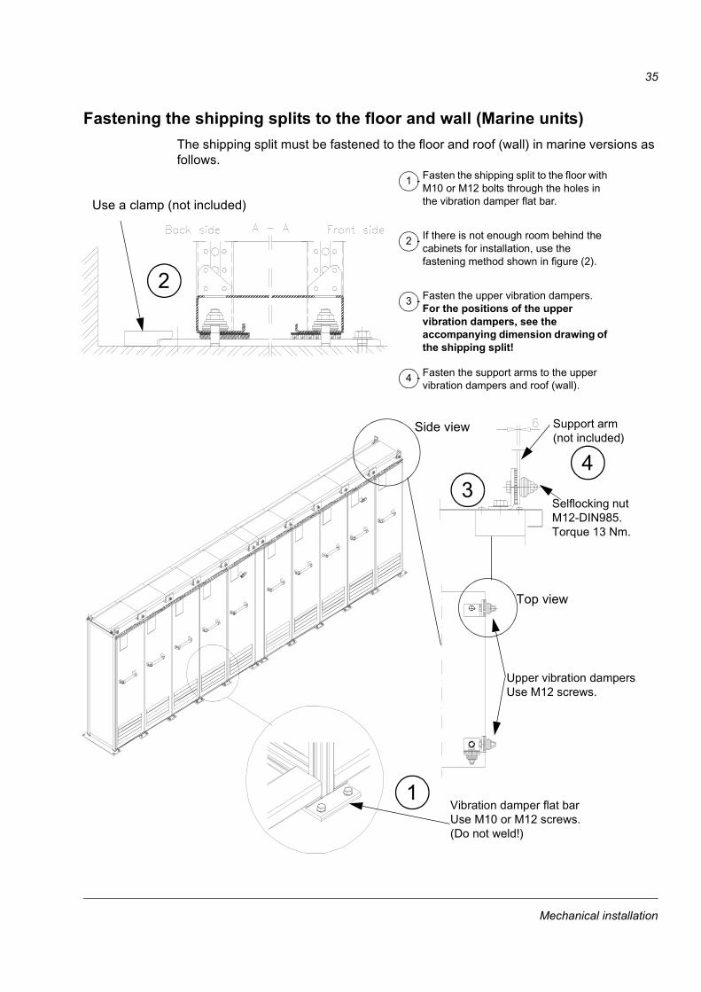
200 mm wide joining section: Remove the intermediate plate hiding the back posts in the joining section. 600 mm wide joining section: Remove the partitioning plates.
Fasten the back post of the joining section with seven screws (below the busbar joining part) to the post of the next cabinet.
Replace the intermediate plate (and the partitioning plate(s) in the upper part of it after connecting the DC Busbars, see section Connecting the DC busbar and the PE busbar).
Connecting the DC busbar and the PE busbarHorizontal main DC busbars and the PE busbar are connected from the front of the 200/600 mm wide busbar joining cabinet. All necessary materials are located in the joining cabinet.
Remove the front metal partitioning plate located in the busbar joining cabinet.
Unscrew the bolts of the joint pieces.
Connect the busbars with the joint pieces (see figure below). For aluminium busbars, joint grease (e.g. TK-Penetral, made by Framatome Connectors USA Inc. Burndy Electrical) must be used to avoid corrosion and to ensure good electrical connection. The oxide layer must be scrubbed off from the joints before applying the grease.
Replace the front metal plate into its original position because of safety of personnel.
Busbar joining section
Intermediate plate Back posts accessible
Partitioning plate
Mechanical installation

38
DC busbar
The DC busbar connection is shown below.
PE busbar
The PE busbar connection is shown below.
Tighten the bolts with a torque wrench to 5570 Nm (4050 ft.-lbs.)
Side view of single busbar connection
Joint pieces11
1
1
1
1
M10Tightening torque: 3540 Nm (2530 ft.-lbs.)
Joint piece
Mechanical installation

39
Lifting a double roof When the drive is equipped with a double roof:
1
Lift the upper part of the roof plate up from the transportation position. Lock the roof to its final position with the M6 screws.
2
Mechanical installation

40
Miscellaneous
Cable conduit in the floor below the cabinetA cable conduit can be constructed below the 400 mm wide middle part of the cabinet. The cabinet weight lies on the two 100 mm wide transverse sections which the floor must carry.
Viewed from above Side view
This area can be used for a cable conduit
With heavy cabinets support the structural C-sections from below.
Prevent the cooling air flow from the cable conduit to the cabinet by bottom plates. To ensure the degree of protection for the cabinet use the original bottom plates delivered with the unit. With user-defined cable entries take care of the degree of protection and fire protection.
Cables
Mechanical installation

41
Electric weldingIt is not recommended to fasten the cabinet by welding.
Cabinets without vibration dampers
If the preferred fastening methods (clamps or holes inside the cabinet) can not be used, proceed as follows:
Connect the return conductor of the welding equipment low to the cabinet frame within 0.5 metres of the welding point.
Cabinets with vibration dampers
If the fastening cannot be done with screws, proceed as follows:
Weld only the flat bar under the cabinet, never the cabinet frame itself.
Clamp the welding electrode onto the flat bar about to be welded or onto the floor within 0.5 metres of the welding point. Do not clamp the electrode on any part of the cabinet frame.
Cool the flat bar with a wet cloth so that the heat is not conducted to the vibration dampers.
WARNING! If the welding return wire is connected improperly, the welding circuit may damage electronic circuits in the cabinets or the vibration damper bolts may weld to the cabinet frame. The vibration dampers will be damaged if their temperature exceeds 120 degrees Celsius.
Mechanical installation

42
Mechanical installation

43
Electrical installation planning
Chapter overviewThis chapter instructs in planning the electrical installation of the drive.
Supply
WARNING! ACS800-17 frame size R11i and above must be supplied with a transformer dedicated to drives and motors or equipment of equal or higher power, or with a transformer equipped with two secondary windings, one of which is dedicated to drives and motors. Resonances might occur if there is capacitive load (e.g. lighting, PC, PLC, small power factor compensation capacitors) in the same network as the ACS800-17. The resonance current may damage a unit in the network.
Supply transformer
Low voltage
Other drives
Low voltage
Other load than drives and motors
Supply transformer
Medium voltage network
ACS800-17
Neighbouring network
Low voltage
Other drives and motors
ACS800-17
or
Medium voltage network
Motors
Other load than drives and motors
Electrical installation planning

44
WARNING! Never connect the mains to the drive output. If frequent bypassing is required, mechanically connected switches or contactors should be employed. Mains voltage applied to the output can result in permanent damage to the unit.
Operation outside the nominal voltage range should not be attempted, as overvoltages can result in permanent damage to the drive.
Earth fault protective functionThe drive is equipped with an internal earth fault protective function to protect the unit against earth faults in the inverter, the motor and the motor cable. This is not a personal safety or a fire protection feature. The internal earth fault protective function is not applicable in parallel connected inverters. For more information on the earth fault parameter settings, see the appropriate firmware manual.
The supply of the drive can be equipped with an optional earth fault protective device, refer to Supply Section Manual.
FusesFuses are needed to protect the supply section and the inverter of the drive in case of an internal short circuit. The ACS800-17 is equipped with internal input fuses introduced in chapter Technical data. If a fuse is blown, it must be replaced with a similar ultrarapid fuse.
Internal fuses
The fuse types used are listed below.
Fuse Type Supply Section
1 Supply AC fuses B1, B2, B3
2 Drive unit DC fuses. Only in frame sizes R11i, R12i, n x R11i and n x R12i.
1
2
Electrical installation planning

45
Motor and output filter selection
WARNING! Operation is not allowed if the motor nominal voltage is less than 1/2 of the drive nominal input voltage, or the motor nominal current is less than 1/6 of the drive nominal output current.
Pulses in the drive outputAs with all frequency converters employing the most modern IGBT inverter technology, the ACS 800 output comprises regardless of output frequency pulses of approximately 1.35 times the mains network voltage with a very short rise time.
The voltage of the pulses can be almost double at the motor terminals, depending on the motor cable properties. This in turn can cause additional stress on the motor insulation.
Modern variable speed drives with their fast rising voltage pulses and high switching frequencies can cause current pulses through the motor bearings which can gradually erode the bearing races.
Protecting the motor windingThe stress on motor insulation can be avoided by using optional ABB du/dt filters. du/dt filters also reduce bearing currents.
Protecting the motor bearingsTo avoid damage to motor bearings, insulated N-end (non-driven end) bearings and output filters from ABB must be used according to the following table. In addition, the cables must be selected and installed according to the instructions given in this manual. Three types of filters are used individually or in combinations:
optional du/dt filter (protects the motor insulation system and reduces bearing currents)
common mode filter (mainly reduces bearing currents)
light common mode filter (mainly reduces bearing currents).
The common mode filter is composed of toroidal cores installed onto the motor cable.
Requirements tableThe following table shows how to select the motor insulation system and when optional du/dt filters, insulated N-end (non-driven end) motor bearings and common mode filters are required. Failure of the motor to fulfil the following requirements or improper installation may shorten motor life or damage the motor bearings.
Electrical installation planning

46
* manufactured before 1992
Note 1: The abbreviations used in the table are defined below.
Man
ufac
ture
r
Motor type Nominal mains voltage
Requirement for
Motor insulation
system
ACS 800 du/dt Filter, Insulated N-end bearing and ACS 800 Common Mode Filter
PN < 100 kW and
Frame Size < IEC 315
100 kW < PN < 350 kW or
Frame Size > IEC 315
PN > 350 kWor
Frame Size > IEC 400
ABB
Random-woundM2_ and M3_
UN < 500 V Standard - + N + N + CMF500 V < UN < 600 V Standard + du/dt + du/dt + N + du/dt + N + LCMF
orReinforced - + N + LMCF + N + CMF
600 V < UN < 690 V Reinforced + du/dt + du/dt + N + du/dt + N + LCMFForm-wound HXR and AM_
380 V < UN < 690 V Standard n.a. + N + CMF + N + CMF
Old* form-wound HX_ and modular
380 V < UN < 690 V Check with the motor manufacturer.
+ du/dt filter with voltages over 500 V + N + CMF
Random-wound HXR and AM_
380 V < UN < 690 V Check with the motor manufacturer.
+ du/dt filter with voltages over 500 V + N + CMF
NON-ABB
Random-wound and form-wound
UN < 420 V Standard: ÛLL = 1300 V
- + N or CMF + N + CMF
420 V < UN < 500 V Standard: ÛLL = 1300 V
+ du/dt + du/dt + N + du/dt + N + CMFor+ du/dt + CMF
orReinforced: ÛLL = 1600 V, 0.2 microsecond rise time
- + N or CMF + N + CMF
500 V < UN < 600 V Reinforced: ÛLL = 1600 V
+ du/dt + du/dt + N + du/dt + N + LCMFor+ du/dt + CMF
orReinforced: ÛLL = 1800 V
- + N or CMF + N + CMF
600 V < UN < 690 V Reinforced: ÛLL = 1800 V
+ du/dt + du/dt + N + du/dt + N + LCMF
Form-wound 600 V < UN < 690 V Reinforced: ÛLL = 2000 V, 0.3 microsecond rise time
n.a. + N + CMF + N + CMF
Abbreviation Definition
UN nominal mains voltage
Electrical installation planning

47
Note 2: Explosion-safe (EX) Motors
The motor manufacturer should be consulted regarding the construction of the motor insulation and additional requirements for explosion-safe (EX) motors.
Note 3: High-output Motors and IP 23 Motors
For motors with higher rated output than what is stated for the particular frame size in IEC 50347 (2001) and for IP 23 motors, the requirements of range 100 kW < PN < 350 kW apply to motors with PN < 100 kW. The requirements of range PN > 350 kW apply to motors with PN within the range of 100 kW < PN < 350 kW.
Note 4: HXR and AMA Motors
All AMA machines (manufactured in Helsinki) to be supplied by a frequency converter have form-wound windings. All HXR machines manufactured in Helsinki since 1997 have form-wound windings.
Note 5: ACS800-17
If voltage is raised by the drive, select the motor insulation system according to the increased intermediate circuit d.c. voltage level, especially in the 500 V (+10%) supply voltage range.
Note 6: Chopper resistor braking When the drive is in braking mode for a large part of its operation time, the intermediate circuit DC voltage of the drive increases, the effect being similar to increasing the supply voltage by up to 20 percent. This should be taken into consideration when determining the motor insulation requirement.
Example: Motor insulation requirement for a 400 V application must be selected as if the drive were supplied with 480 V.
ÛLL peak line-to-line voltage at motor terminals which the motor insulation must withstand
PN motor nominal power
du/dt du/dt filter
CMF common mode filter: 3 toroidal cores per each motor cable
LCMF light common mode filter: 1 toroidal core per each motor cable
N N-end bearing: insulated motor non-driven end bearing
n.a. Motors of this power range are not available as standard units. Consult the motor manufacturer.
Electrical installation planning
48
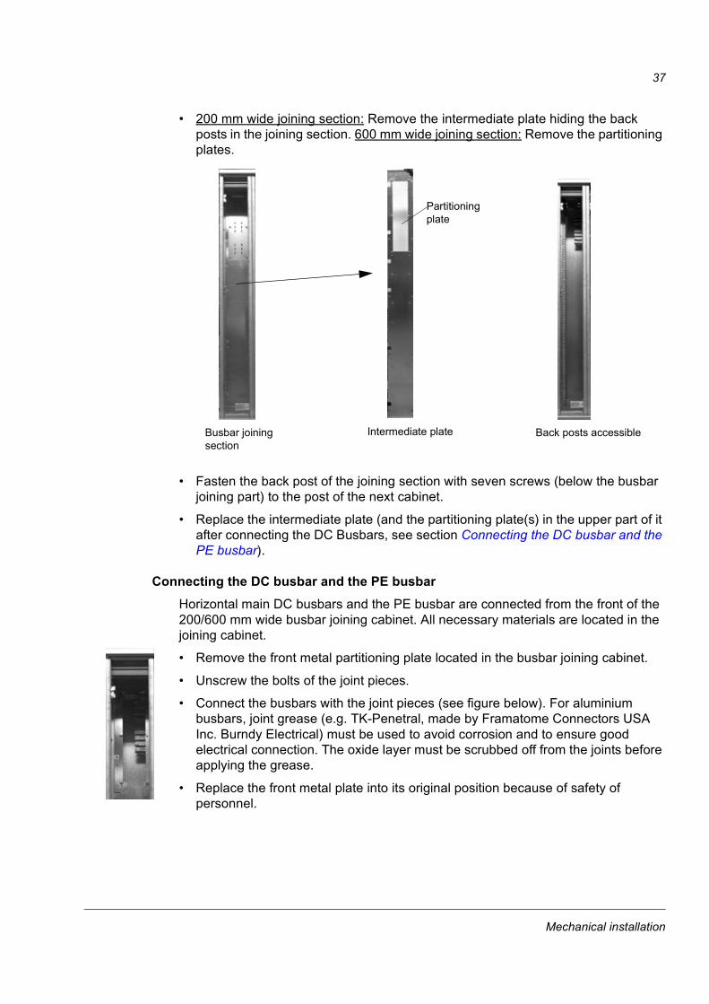
Note 7: The table applies to NEMA motors with the following heading.
Note 8: Calculating the rise time and the peak line-to-line voltage
The peak line-to-line voltage at the motor terminals generated by the drive as well as the voltage rise time depend on the cable length. The requirements for the motor insulation system given in the table are worst case requirements covering the drive installations with 30 metre and longer cables. The rise time can be calculated as follows: t = 0.8 · ÛLL/(du/dt). Read ÛLL and du/dt from the diagrams below.
PN < 134 HPand Frame Size < NEMA 500
134 HP < PN < 469 HPor Frame Size > NEMA 500
PN > 469 HP
du/dt / (kV/µs)
ÛLL/ UN
Cable length (m)0 100 200 300 400
43.5
32.5
21.5
10.5
0
du/dt / (kV/µs)
ÛLL/ UN
43.5
32.5
21.5
1
0 100 200 300 400
0.50
Cable length (m)
Without du/dt Filter With du/dt Filter
Electrical installation planning

49
Power cable selectionThe mains and motor cables must be dimensioned according to local regulations:
The cable must be able to carry the drive load current. See chapter Technical data cable types for different load currents.
The cable terminals of the drive warm up to 60 °C (140 °F) during operation. The cable must be rated for at least 60 °C (140 °F) maximum operating temperature.
The cable must withstand the short-circuit current given in chapter Technical data.
The inductance and impedance of the cable must be rated according to permissible touch voltage appearing under fault conditions (so that the fault point voltage will not rise too high when an earth fault occurs).
The inverter module has an electronic overload protection which limits the largest permissible load current.
If multiple motors are connected to the inverter module, a separate thermal overload switch or a compact circuit breaker must be used for protecting the cable and the motor. These devices may require a separate fuse to cut off the short circuit current.
The rated voltage of the mains cables should be Uo/U = 0.6/1 kV for 690 VAC rated equipment. (Uo = rated voltage between the conductor and the earth, U = rated voltage between the conductors.) For the North American market, 600 VAC rated cable is accepted for 600 VAC rated equipment. As a general rule, the rated voltage for the motor cables should be minimum Uo/U = 0.6/1 kV.
Symmetrical shielded motor cable must be used (figure below). Four-conductor system is allowed for mains cabling, but shielded symmetrical cable is recommended. To operate as a protective conductor, the shield conductivity must be at least 50 % of the conductivity of the phase lead.
Compared to a four-conductor system, the use of symmetrical shielded cable reduces electromagnetic emission of the whole drive system as well as motor bearing currents and wear.
The motor cable and its PE pigtail should be kept as short as possible in order to reduce electromagnetic emission as well as capacitive current.
Electrical installation planning

50
AlternativesPower cable types that can be used with the drive are represented below.
Motor cable shieldTo effectively suppress radiated and conducted radio-frequency emissions, the shield conductivity must be at least 1/10 of the phase conductor conductivity. The effectiveness of the shield can be evaluated e.g. on the basis of the shield inductance, which must be low and only slightly dependent on the frequency. These requirements are easily met with a copper or aluminium shield/armour. The minimum requirement of the motor cable shield of the drive is shown below. It consists of a concentric layer of copper wires with an open helix of copper tape. The better and tighter the shield, the lower the emission level and the bearing currents.
Symmetrical shielded cable: three phase conductors and a concentric or otherwise symmetrically constructed PE conductor, and a shield
Recommended
PE conductor and shield
Shield Shield
A separate PE conductor is required if the conductivity of the cable shield is < 50 % of the conductivity of the phase conductor.
A four-conductor system: three phase conductors and a protective conductor.Not allowed for motor cable.
Shield
PE
PE
PE
Insulation jacket Copper wire screen Helix of copper tape
Cable core
Inner insulation
Electrical installation planning

51
Control cable selectionAll control cables must be shielded. As a general rule, the control signal cable shield should be earthed directly in the drive. The other end of the shield should be left unconnected or earthed indirectly via some nanofarad high-frequency, high-voltage capacitor (e.g. 3.3 nF / 3000 V). The screen can also be earthed directly at both ends if they are in the same earth line with no significant voltage drop between the end points.
Twisting the signal wire with its return wire reduces disturbances caused by inductive coupling. Pairs should be twisted as close to terminals as possible.
A double shielded twisted pair cable (Figure a, e.g. JAMAK by NK Cables, Finland) must be used for analogue signals and the pulse encoder signals. Employ one individually shielded pair for each signal. Do not use common return for different analogue signals.
A double shielded cable is the best alternative for low voltage digital signals but single shielded twisted multipair cable (Figure b) is also usable.
The analogue and digital signals should be run in separate, screened cables.
Relay-controlled signals, providing their voltage does not exceed 48 V, can be run in the same cables as digital input signals. It is recommended that the relay-controlled signals be run as twisted pairs.
Never mix 24 VDC and 115 / 230 VAC signals in the same cable.
Co-axial cableRecommendations for use with ACS 800 Application Controller:
75 Ω type
RG59 cable with diameter 7 mm or RG11 cable 11 mm
The maximum cable length is 300 m
Optical cableWhen cutting the cable, for example with cutters, the optical cable ends become rough and may cause damping in the cable; the cable ends, therefore, should be ground with fine sandpaper.
aA double shielded twisted pair cable
bA single shielded twisted multipair cable
Electrical installation planning

52
Relay cableThe cable type with braided metallic screen (e.g. ÖLFLEX LAPPKABEL, Germany) has been tested and approved by ABB.
Control panel cableIn remote use, the cable connecting the Control Panel to the drive must not exceed 3 metres. The cable type tested and approved by ABB is used in Control Panel option kits.
Emergency stop devicesEmergency stop devices must be installed at each operator control station and at other operating stations where emergency stop may be required. Pressing the key on the Control Panel of the drive does not generate an emergency stop of the motor or separate the drive from dangerous potential. Line Contactor, air circuit breaker and Emergency Stop Switch are factory installed as option for the drive.
An emergency stop function has been provided (optional) in the drive to stop and switch off the whole drive. The available modes are: Immediate Removal of Power and Controlled Emergency Stop (with thyristor supply only). The emergency stop function must not be used as the normal mode of stopping the drive.
Immediate removal of power (Category 0)After pressing the emergency stop push-button the power semiconductors of the inverter are blocked (coast stop) and the main contactor (or air circuit-breaker) is opened immediately. No attention is paid to deceleration of the speed of the motor shaft after the emergency stop is activated.
Controlled emergency stop (Category 1)The installer has to make sure that the overriding control fulfils the requirements of EN 60204-1, category 1.
Upon receiving the emergency stop signal, each inverter starts braking (by ramp or torque limits) and acknowledges the signal by closing its output contact. (If the emergency stop signal is not acknowledged by all inverters within two seconds, the supply main contactor is opened.)
After a delay set with a time relay in the emergency stop circuitry, the supply main contactor is opened. The time delay should be set slightly longer than the inverter stop ramps to ensure controlled braking of all inverters.
RestartIn order to restart the drive system after an emergency stop, the emergency stop push-button has to be released and a reset given before the main contactor (or air circuit-breaker) can be closed and the drive started.
Electrical installation planning
53
Prevention of unexpected startThe drive can be equipped with an optional Prevention of Unexpected Start according to the standards: EN 292-1: 1991, EN 292-2: 1991, EN 954-1: 1996, EN 60204-1-1: 1992 + Corr. 1993 and EN 1037: 1995.
The function is achieved by disconnecting the control voltage to the power semiconductors of the inverter. Thus it is not possible for the power semiconductors to switch and generate the AC voltage needed to rotate the motor. In case of faulty main circuit components, the DC voltage from the busbar can be connected to the motor but an AC motor cannot rotate without the field generated by the AC voltage.
The operator activates the Prevention of Unexpected Start with a switch mounted on the control desk. When Prevention of Unexpected Start is activated, the switch is turned to position 0. A signal lamp will be lit on the control desk, indicating that Prevention of Unexpected Start is activated.
WARNING! Prevention of Unexpected Start does not disconnect the voltage of the main and auxiliary circuits. Therefore maintenance work on electrical parts can only be carried out after disconnecting the drive system.
Power factor compensation capacitorsPower factor compensation capacitors and surge absorbers must not be connected to the motor cables. These devices are not designed to be used with frequency converters, and will degrade motor control accuracy. They can cause permanent damage to the drive or themselves due to the rapid changes in the output voltage.
If there are power factor compensation capacitors in parallel with the drive make sure that the capacitors and the drive are not charged simultaneously to avoid voltage surges which might damage the unit.
Output contactorsIf a contactor is used between the output of the drive and the motor with DTC control mode selected, the output voltage of the drive must be controlled to zero before the contactor is opened: ACS 800 units via parameter 21.3, choice COAST. If choice RAMP is selected, the output of the ACS 800 must be controlled to zero via parameter 16.1 by giving zero V DC to the selected digital input. Otherwise the contactor will be damaged. In scalar control the contactor can be opened with the drive running.
Varistors or RC networks (AC) or diodes (DC) should be used to protect against voltage transients generated by contactor coils. The protective components should be mounted as close as possible to the contactor coils. Protective components should not be installed at the connection terminals of the control board.
Electrical installation planning

54
Relay contactsWhen used with inductive loads (relays, contactors, motors), the relay contacts of the drive must be protected with varistors or RC networks (AC) or diodes (DC) against voltage transients. The protective components should not be installed at the connection terminals of the control board.
Connection of motor thermistor to drive
WARNING! IEC 664 requires double or reinforced insulation between live parts and the surface of accessible parts of electrical equipment which are either non-conductive or conductive but not connected to the protective earth.
To fulfil this requirement, the connection of a thermistor (and other similar components) to the digital inputs of the drive can be implemented in three alternate ways:
There is double or reinforced insulation between the thermistor and live parts of the motor.
Circuits connected to all digital and analogue inputs of the drive are protected against contact, and insulated with basic insulation (the same voltage level as the converter main circuit) from other low voltage circuits.
An external thermistor relay is used. The insulation of the relay must be rated for the same voltage level as the converter main circuit.
Cable routingThe motor cable should be installed away from other cable routes. Motor cables of several frequency converters can be run in parallel installed next to each other. It is recommended that the motor cable, mains cable and control cables be installed on separate trays (minimum distance 500 mm). Long parallel runs of motor cable with other cables should be avoided in order to decrease electromagnetic interference caused by the rapid changes in the frequency converter output voltage.
Where control cables must cross power cables make sure they are arranged at an angle as near to 90 degrees as possible. Extra cables should not be run through the drive.
The cable trays shall have good electrical bonding to each other and to the earthing electrodes. Aluminium tray systems can be used to improve local equalizing of potential.
Electrical installation planning

55
Below is a diagram of cable routing.
Control cable ducts
Note: If safety switches, contactors, connection boxes or similar equipment are used in the motor cable, they should be installed in a metal enclosure with 360 degrees earthing for the screens of both the incoming cable and the outgoing cable, or the screens of the cables should otherwise be connected together.
90 ° min. 500 mm
Motor cable Mains cable
Control cables
Drive
230 V24 V24 V 230 V
Lead 24 V and 230 V control cables in separate ducts inside the cabinet.
Not allowed unless the 24 V cable is insulated for 230 V or insulated with an insulation sleeving for 230 V.
Electrical installation planning

56
Electrical installation planning

57
Electrical installation
WARNING! The electrical installation described in this chapter should only be carried out by a qualified electrician. The Safety Instructions on the first pages of this manual must be followed. Negligence of these instructions can cause injury or death.
Chapter overviewThis chapter describes the electrical installation of the drive.
Insulation checksEvery drive has been tested for insulation between main circuit and cabinet (2500 V rms 50 Hz for 1 minute) at the factory. Therefore there is no need to check the insulation of the unit again. When checking the insulation of the assembly, proceed in the following manner:
WARNING! Insulation checks must be performed before connecting the drive to the mains. Before proceeding with the insulation resistance measurements make sure that the drive is disconnected from the mains.
Motor and motor cable Check that the motor cable is disconnected from the drive output terminals U2,
V2 and W2.
Measure the insulation resistances of motor cable and the motor between each phase and Protective Earth using a measuring voltage of 1 kV d.c. The insulation resistance must be higher than 1 MΩ.
PE
ΩM
R > 1 MΩ
Electrical installation

58
Input power cable wiring diagramsThis section describes the input power cable connections of the drive. The following Motor cable wiring diagrams section provides some basic instructions for the routing and mechanical connection of cables. The mechanical cable connections are basically the same, whether for the incoming supply or an inverter; different are the cabinet dimensions and the location of the terminals for the cables. The cabling direction may also vary (top or bottom).
The N conductor is not normally used with frequency converters although it is visible in the following diagrams.
Low power supplyA low current (< 300 A) cable connection when one cable is sufficient is represented below.
L1L2L3N
Transformer ConverterL1L2L3
PEPE
Factory main earthing bus
2)
1)1)
L1
L3 L2
L1
L3 L2
N
2) not used if the supply cable screen operates as a protective conductor
1) as short as possible (low inductance)
Electrical installation

59
High power supplyBusbar connection
A high current (> 300 A) busbar connection is represented below.
Cable bus system
The connection of a high current (> 300 A) cable bus system that consists of several cables is represented below. In this system, less conductor material is needed due to better cooling of separate conductors.
L1L2L3N
Transformer ConverterL1L2L3
PEPE
Factory main earthing bus
1) 1) Connect the metal conduit of the busbar system (or the metal of the bus duct) to PE at either one end or both ends.
Metal conduit (shield)
L1 L2 L3 N
Note: The paint should be removed to allow a good connection to the cabinet frames throughout the whole perimeter of the metal conduit (or a bus duct). The metal conduit (or the bus duct metal) should be electrically continuous throughout its complete length.
It is recommended to arrange the cables as shown alongside to achieve a current distribution as accurate as possible. Air between cables is required for cooling.
L1L3 L2
L1L3 L2
L1L3 L2
L1 L3L2 N L1 L3L2 NL1 L3L2 N
L1L2L3N
Transformer ConverterL1L2L3
PEPE
Factory main earthing bus
Note: Current derating of the cables is required when installing the cables in a cable tray. This derating factor must be taken into account as per the local electrical safety codes.
Electrical installation

60
Single-core cables with concentric protective shields
When single-core cables equipped with concentric protective shields (metal) are used, the phase current will induce voltage to the cable shield. If the shields are connected to each other at both ends of the cable, current will flow in the cable shield. In order to prevent this and to ensure personal safety, the cable shield must be connected only to PE at the transformer side and insulated on the converter side. The connection is represented below.
L1L2L3N
Transformer ConverterL1L2L3
PEPE
Factory main earthing bus
Concentric shield
Electrical installation

61
Motor cable wiring diagramsMotor cable connections for different cable types are represented below. For minimum radio frequency interference (RFI) at the motor end, earth the cable screen 360 degrees at the lead-through or earth the cable by twisting the screen (flattened width > 1/5 · length).
Separate protective conductor
A separate PE conductor system is used only if local safety regulations do not allow earthing of the drive and the motor merely through the cable screen. This solution increases motor bearing currents compared to symmetrical shielded cable, thus causing extra wear.
L1
L2L3
U2 V2 W2PE
Drive Section
U1V1
W1PE M
3 ~
U2 V2 W2PE
Drive Section
U1V1
W1PE M
3 ~
U2 V2 W2PE
Drive Section
U1V1
W1PE M
3 ~
L1
L3 L2
L1
L3 L2
Concentric Al/Cu-shield Concentric Al/Cu-shield and steel or aluminium armour
Galvanised steel or copper armour
Separate protective conductor
Factory main earth bus
Factory main earth bus
Factory main earth bus
Electrical installation

62
Single invertersMotor cable connections with parallel symmetrical cables are represented below.
Parallel connected invertersMotor cable connections with parallel connected inverters are presented below. Parallel connected cables are drawn as single cables to simplify the drawings.
Requirements for parallel connected cables and cables for motors with two separate windings are given as follows:
The maximum allowed difference in cable length is 5 % i.e. the length of the longest cable divided by that of the shortest cable must be less than or equal to 1.05: lmax/lmin < 1.05.
Cables must be of the same type and have equal cross-sectional areas.
2 x R11i/R12i without common motor connection terminal
Motor cable connections with parallel symmetrical cables for two phase module blocks with a common motor are represented below.Note: With two parallel phase module blocks, the number of cables must be n x 2, where n = 1, 2, 3... With four parallel blocks the number of cables must be n x 4, where n = 1, 2, 3... Otherwise the output cabling must be done from a separate output cubicle.
U1V1 W1
1 2 3 1 2 3 1 2 3
U2 V2 W2
1 2 3 1 2 3 1 2 3
M3 ~
PE
OUTPUT
Inverter
Electrical installation
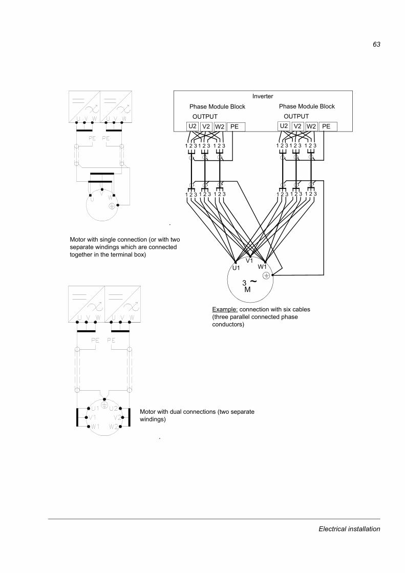
63
1 2 3 1 2 3 1 2 3
U2 V2 W2
1 2 3 1 2 3 1 2 3
M3 ~
PEOUTPUT
Phase Module Block
U2 V2 W2 PEOUTPUT
Phase Module Block
1 2 3 1 2 3 1 2 3
1 2 3 1 2 3 1 2 3
V1W1U1
Inverter
Motor with single connection (or with two separate windings which are connected together in the terminal box)
Motor with dual connections (two separate windings)
Example: connection with six cables (three parallel connected phase conductors)
Electrical installation

64
Inverters with common motor connection terminal
Motor cable connections for parallel connected inverters with a common output cubicle(s) are presented below.
2 x R11i/R12i 4 x R11i/R12i
Motor with single connection (or with two separate windings which are connected together in the terminal box)
Motor with dual connections (two separate windings)
Electrical installation

65
4 x R11i/R12i without common motor connection terminal
Motor cable connections for four parallel connected inverters without a common output cubicle are presented below.
Motor with single connection (or with two separate windings which are connected together in the terminal box)
Motor with dual connections (two separate windings)
Electrical installation

66
Location of power cable terminals (R6i, R7i)The cable connections of a bottom entry unit of frame size R7i are represented below. In frame size R6i, the terminals are located similarly.
PE terminal Isolated stud terminals for motor cable connection: U2, V2, W2.of the cabinet
Busbars for input cable connection: L1, L2, L3.
Electrical installation

67
Location of power cable terminals (R8i, R9i)The cable connections of a bottom entry unit of frame size R9i are represented below. In frame size R8i, the terminals are located similarly.
PE terminal Busbars for motor cable connection: U2, V2, W2
of the cabinet
Busbars for input cable connection: L1, L2, L3
Electrical installation

68
Location of motor cable terminals (R11i, R12i, n x R11i, n x R12i and top exit)
This cubicle is used for
motor cable entry and exit through the top of the cabinet
common motor output of parallel connected inverter modules R11i and R12i (optional)
common motor output of parallel connected inverter modules when the number of cables does not match the rule given on page 62 (optional).
Cable entry from the bottom is shown below. The top entry is accomplished in the same way except that cables are entering or exiting the cabinet from the top.
PE terminal of the cabinet
Motor cable
Busbar for motor cable connection
PE conductor / shield of the cable
Cable lugs
These busbars connect inverter units parallel
U2
V2
W2
Electrical installation

69
About power cable busbars and use of cable lugsA view of power cable busbars of large drive units is shown below. If necessary, the same screw can be used for connecting two cable lugs (on both sides of the busbar). Cable lugs with one or two holes can be used. Always use a torque wrench for tightening the busbar connections. Note: In inverter modules R6i and R7i, only one cable lug can be connected to a busbar screw.
40 m
m
100 mm
50
Electrical installation

70
Use of conductive sleeves of power cable lead-throughsConductive sleeves are supplied by ABB as an option to provide 360° high-frequency earthing for motor cables. Follow these instructions:
If fire insulation is used, make an opening to the mineral wool sheet according to the diameter of the cable.
Pull the cable into the cabinet through the conductive sleeve.
If a rubber grommet is used, slide it onto the cable.
Connect phase conductors to terminals.
Twist the shield wires of the cable together and connect them to earth terminal or PE busbar.
Peel off 3 to 5 cm of the outer insulation of the cable above the entry plate for the 360° high-frequency earthing.
Fasten the conductive sleeve to the cable shield with a cable tie.
Seal the slot between the cable and mineral wool sheet (if used) with sealing compound (e.g. CSD-F, ABB brand name DXXT-11, code 35080082).
Tie up the unused conductive sleeves with cable ties.
Cable entry from below for power cables of drive (IP 21 and IP 22) is shown below. Tighten the EMC sleeve on the stripped part of the cable with cable ties. For IP 54 units, add a rubber grommet on the cable under the lead-through plate.
EMC sleeve
Lead-through plate
Strip this part of the cable
Cable shield
Base plate
PE terminal
Strain relief
Electrical installation

71
Use of common mode filters on the motor cableIf common mode filter or light common mode filter is required (see Electrical installation planning / Motor and output filter selection / Requirements table), lead the motor cable phase conductors through the toroidal cores as follows:
Connect the twisted cable screen to the PE terminal.
Wrap the phase conductors together with the silicon rubber tape delivered with the toroidal cores to provide thermal insulation for the conductor insulator. Cover the part of the cable which will be left inside the core(s) + 20 mm below. Approximately 1.5 metres of tape is needed per cable. Each turn must overlap the previous turn by half the width of the tape.
Bind the conductors tightly with non-conductive electrical tape and a heat-resisting non-metallic cable tie in order to prevent conductor insulation damage caused by the core edges.
Slide the core(s) onto the taped part of the phase conductors.
Bind the cores together and onto the taped part of the phase conductors with heat-resisting non-metallic cable ties.
Common Mode Filter Light Common Mode Filter
2
3
1
5
Code 64315439-B
4
Electrical installation

72
Control cable connections at shipping split jointsSome control wires are chained through the shipping splits. 230/115 V voltage transformer, uninterrupted power supply (UPS) and emergency stop wires are chained via terminal blocks X25 at the upper left hand corner of the fields next to the busbar joining sections. Connect the loose wires to the next X25 terminal block. Connect the loose wires not coming from X25 to the destinations marked on the wire ends. Ensure that no unconnected wire ends are left which will be powered when the supply voltage is switched on.
Last shipping splitShipping split
Busbarjoiningsection
X25
ACU
UPS
X25
230/115 V
Normal voltage (neutral)
Normal voltage (230 V a.c. / 115 V a.c.)
UPS voltage (neutral)
UPS voltage (230 V a.c.)
X25
X25
Several shipping splits
Electrical installation

73
External control cable connections Connect the control cables to the appropriate terminals on the RMIO board (or optional terminal block X2, or other options on the DIN rail on the left-hand side of the cabinet). Connect the twisted screen (as short as possible) to the earthing terminal .
EMC Earthing at the cable entry360° high frequency earthing of the control cable screen at the cable entry is available as an option from ABB (figure below).
Special for top entry
When each cable has its own rubber grommet, sufficient IP and EMC protection can be achieved. However, if very many control cables come to one cabinet, plan the installation beforehand as follows:
Make a list of the cables coming to the cabinet.
Sort the cables going to the left into one group and the cables going to the right into another group to avoid unnecessary crossing of cables inside the cabinet.
Sort the cables in each group according to size.
Group the cables for each grommet as follows:
Cable diameter in mm Max. number of cables per grommet
< 13 4
< 17 3
< 25 2
> 25 1
EMI conductive cushions
Base plate
Holes for position screws
Side view Top view
Lead-through plate
Electrical installation

74
Divide the bunches so that cables will be arranged according to size between the EMI conductive cushions.
Bottom and top entry
Proceed as follows:
Loosen the lead-through plate position screws. Pull the two parts apart.
Bottom entryLead the cable inside the cabinet through the EMI conductive cushions.Top entry Lead the cable inside the cabinet through the grommet and the EMI conductive cushions. If you have several cables, bunch them together at the grommet, but ensure that each cable has a proper contact to the cushions on both sides.
Strip off the cable plastic sheath above the base plate (just enough to ensure proper connection of the bare screen and the EMI conductive cushions).
Earth the screen between the EMI conductive cushions:
If the outer surface of the screen is conductive:
Push the two parts of the lead-through plate together so that the EMI conductive cushions press tightly round the bare screen.
If the outer surface of the screen is covered with non-conductive material:
Thinnest cable
Thickest cable
View from below
Electrical installation

75
Cut the screen at the midpoint of the bare part. Be careful not to cut the conductors.
Turn the screen inside out to expose its conductive surface.
Cover the turned screen and the stripped cable with copper foil to keep the shielding continuous. Note: The earthing wire (if present) must not be cut.
Push the two parts of the lead-through plate together so that the EMI conductive cushions press tightly round the foil-covered screen.
Lock the two parts of the lead-through plate by tightening the positioning screws.
Top entry: If more than one cable go through a grommet, the grommet must be sealed by Loctite 5221 (catalogue number 25551).
Cable screenScreened twisted pair
Earthing wire
Copper foil
Stripped cable Conductive surface of the screen exposed
Stripped part covered with copper foil
Side view
Apply Loctite 5221 inside the grommet.
Attach control cables to the supporting plate.
Connect the earthing wire to the PE busbar.
Electrical installation

76
Installation of optional modules and PCThe optional module (such as fieldbus adapter, I/O extension module and the pulse encoder interface) is inserted in the optional module slot of the RMIO board and fixed with two screws. See the appropriate optional module manual for cable connections.
Cabling of I/O and fieldbus modules
Pulse encoder installationSee Pulse Encoder Interface Module RTAC-0x Users Manual [3AFE 64486853 (english)] for the pulse encoder insulation requirements and connections.
The pulse encoder shall be insulated from the motor stator or rotor in order to prevent currents from finding their way out from the drive shaft through the encoder with resulting damage to the bearings in both the motor and the encoder.
Shield
Module
234
1
As short as possible
Grounding wire of the outer shield
Strain relief witha cable tie
Alternative to a)
a)
Electrical installation

77
Pulse encoder module cabling
Fibre optic link A DDCS fibre optic link is provided via the RDCO optional module for PC tools, master/follower link, NDIO, NTAC, NAIO, AIMA I/O module adapter and fieldbus adapter modules of type Nxxx. See RDCO Users Manual [3AFE 64492209 (English)] for the connections. Observe colour coding when installing fibre optic cables. Blue connectors go to blue terminals, and grey connectors to grey terminals.
When installing multiple modules on the same channel, connect them in a ring.
Strain reliefwith a cable tie
234
1
Clamp as close to the terminals as possible.
As short as possible
Note1: If the encoder is of unisolated type, ground the encoder cable at the drive end only. If the encoder is galvanically isolated from the motor shaft and the stator frame, ground the encoder cable shield at the drive and the encoder end.Note 2: Twist the pair cable wires.Note 3: The grounding wire of the outer shield of the cable can alternatively be connected to the SHLD terminal of the RTAC module.
6 5 4 3 2 16 5 4 3 2 1 8 7
08
4
C
26
A E
1
3579
B DF
CHASSIS
GND
NODE ID
SHLD
RTAC-01PULSE ENCO
DER INTERFACE
X2X1
WD/
INIT
CHB
CHASHLD
CHA+
CHA-
CHB+
CHB-
CHZ+
CHZ-
0 V0 VV OUT
+15V
V IN
+24V
a)
Alternative to a)
Electrical installation

78
Electrical installation

79
Motor control and I/O board (RMIO)
Chapter overviewThis chapter shows
external control connections to the RMIO board for the ACS800 Standard Application Program (Factory Macro)
specifications of the inputs and outputs of the board.
To which products this chapter appliesThis chapter applies to ACS800 units which employ the RMIO board.
Note for external power supplyWARNING! If the RMIO board is supplied from an external power source, the loose end of the cable removed from the RMIO board terminal must be secured mechanically to a location where it cannot come into contact with electrical parts. If the screw terminal plug of the cable is removed, the wire ends must be individually insulated.
Motor control and I/O board (RMIO)

80
External control connections (non-US)External control cable connections to the RMIO board for the ACS800 Standard Application Program (Factory Macro) are shown below. For external control connections of other application macros and programs, see the appropriate Firmware Manual.
X201 VREF- Reference voltage -10 VDC, 1 kohm < RL <
10 kohm2 GNDX211 VREF+ Reference voltage 10 VDC, 1 kohm < RL <
10 kohm2 GND3 AI1+ Speed reference 0(2) ... 10 V, Rin >
200 kohm4 AI1-5 AI2+ By default, not in use. 0(4) ... 20 mA, Rin =
100 ohm6 AI2-7 AI3+ By default, not in use. 0(4) ... 20 mA, Rin =
100 ohm8 AI3-9 AO1+ Motor speed 0(4)...20 mA 0...motor nom.
speed, RL < 700 ohm10 AO1-11 AO2+ Output current 0(4)...20 mA 0...motor
nom. current, RL < 700 ohm12 AO2-X221 DI1 Stop/Start2 DI2 Forward/Reverse 1)
3 DI3 Not in use4 DI4 Acceleration & deceleration select 2)
5 DI5 Constant speed select 3)
6 DI6 Constant speed select 3)
7 +24V +24 VDC max. 100 mA8 +24V9 DGND Digital ground10 DGND Digital ground11 DIIL Start interlock (0 = stop) 4)
X231 +24V Auxiliary voltage output, non-isolated,
24 VDC 250 mA2 GNDX251 RO11 Relay output 1: ready2 RO123 RO13X261 RO21 Relay output 2: running2 RO223 RO23X271 RO31 Relay output 3: fault (-1)2 RO323 RO33
=
=
Fault
A
rpm
1) Only effective if par. 10.03 is set to REQUEST by the user.
2) 0 = open, 1 = closed
3) See par. group 12 CONSTANT SPEEDS.
4) See parameter 21.09 START INTRL FUNC.
DI4 Ramp times according to0 parameters 22.02 and 22.031 parameters 22.04 and 22.05
DI5 DI6 Operation0 0 Set speed through AI11 0 Constant speed 10 1 Constant speed 21 1 Constant speed 3
Terminal block size: cables 0.3 to 3.3 mm2 (22 to 12 AWG) Tightening torque: 0.2 to 0.4 Nm (2 to 4 lbf in.)
Motor control and I/O board (RMIO)

81
External control connections (US)External control cable connections to the RMIO board for the ACS800 Standard Application Program (Factory Macro US version, +N665) are shown below. For external control connections of other application macros and programs, see the appropriate Firmware Manual.
X201 VREF- Reference voltage -10 VDC, 1 kohm < RL <
10 kohm2 GNDX211 VREF+ Reference voltage 10 VDC, 1 kohm < RL <
10 kohm2 GND3 AI1+ Speed reference 0(2) ... 10 V, Rin >
200 kohm4 AI1-5 AI2+ By default, not in use. 0(4) ... 20 mA, Rin =
100 ohm6 AI2-7 AI3+ By default, not in use. 0(4) ... 20 mA, Rin =
100 ohm8 AI3-9 AO1+ Motor speed 0(4)...20 mA 0...motor nom.
speed, RL < 700 ohm10 AO1-11 AO2+ Output current 0(4)...20 mA 0...motor
nom. current, RL < 700 ohm12 AO2-X221 DI1 Start ( )2 DI2 Stop ( )3 DI3 Forward/Reverse 1)
4 DI4 Acceleration & deceleration select 2)
5 DI5 Constant speed select 3)
6 DI6 Constant speed select 3)
7 +24V +24 VDC max. 100 mA8 +24V9 DGND Digital ground10 DGND Digital ground11 DIIL Start interlock (0 = stop) 4)
X231 +24V Auxiliary voltage output, non-isolated,
24 VDC 250 mA2 GNDX251 RO11 Relay output 1: ready2 RO123 RO13X261 RO21 Relay output 2: running2 RO223 RO23X271 RO31 Relay output 3: fault (-1)2 RO323 RO33
=
=
Fault
A
rpm
Terminal block size: cables 0.3 to 3.3 mm2 (22 to 12 AWG) Tightening torque: 0.2 to 0.4 Nm (2 to 4 lbf in.)
1) Only effective if par. 10.03 is set to REQUEST by the user.
2) 0 = open, 1 = closed
3) See par. group 12 CONSTANT SPEEDS.
4) See parameter 21.09 START INTRL FUNC.
DI4 Ramp times according to0 parameters 22.02 and 22.031 parameters 22.04 and 22.05
DI5 DI6 Operation0 0 Set speed through AI11 0 Constant speed 10 1 Constant speed 21 1 Constant speed 3
Motor control and I/O board (RMIO)
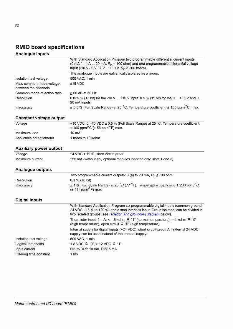
82
RMIO board specificationsAnalogue inputs
With Standard Application Program two programmable differential current inputs (0 mA / 4 mA ... 20 mA, Rin = 100 ohm) and one programmable differential voltage input (-10 V / 0 V / 2 V ... +10 V, Rin > 200 kohm).The analogue inputs are galvanically isolated as a group.
Isolation test voltage 500 VAC, 1 minMax. common mode voltage between the channels
±15 VDC
Common mode rejection ratio > 60 dB at 50 HzResolution 0.025 % (12 bit) for the -10 V ... +10 V input. 0.5 % (11 bit) for the 0 ... +10 V and 0 ...
20 mA inputs.Inaccuracy ± 0.5 % (Full Scale Range) at 25 °C. Temperature coefficient: ± 100 ppm/°C, max.
Constant voltage outputVoltage +10 VDC, 0, -10 VDC ± 0.5 % (Full Scale Range) at 25 °C. Temperature coefficient:
± 100 ppm/°C (± 56 ppm/°F) max.Maximum load 10 mAApplicable potentiometer 1 kohm to 10 kohm
Auxiliary power outputVoltage 24 VDC ± 10 %, short circuit proofMaximum current 250 mA (without any optional modules inserted onto slots 1 and 2)
Analogue outputsTwo programmable current outputs: 0 (4) to 20 mA, RL < 700 ohm
Resolution 0.1 % (10 bit)Inaccuracy ± 1 % (Full Scale Range) at 25 °C (77 °F). Temperature coefficient: ± 200 ppm/°C
(± 111 ppm/°F) max.
Digital inputsWith Standard Application Program six programmable digital inputs (common ground: 24 VDC, -15 % to +20 %) and a start interlock input. Group isolated, can be divided in two isolated groups (see Isolation and grounding diagram below).Thermistor input: 5 mA, < 1.5 kohm 1 (normal temperature), > 4 kohm 0 (high temperature), open circuit 0 (high temperature).Internal supply for digital inputs (+24 VDC): short circuit proof. An external 24 VDC supply can be used instead of the internal supply.
Isolation test voltage 500 VAC, 1 minLogical thresholds < 8 VDC 0, > 12 VDC 1Input current DI1 to DI 5: 10 mA, DI6: 5 mAFiltering time constant 1 ms
Motor control and I/O board (RMIO)

83
Relay outputsThree programmable relay outputs
Switching capacity 8 A at 24 VDC or 250 VAC, 0.4 A at 120 VDCMinimum continuous current 5 mA rms at 24 VDCMaximum continuous current 2 A rmsContact material Silver Cadmium Oxide (AgCdO)Isolation test voltage 4 kVAC, 1 minute
DDCS fibre optic linkWith optional communication adapter module RDCO. Protocol: DDCS (ABB Distributed Drives Communication System)
The RMIO board as well as the optional modules attachable to the board fulfil the Protective Extra Low Voltage (PELV) requirements stated in EN 50178.
Motor control and I/O board (RMIO)

84
Isolation and grounding diagram
X201 VREF2 GNDX211 VREF2 GND3 AI1+4 AI1-5 AI2+6 AI2-7 AI3+8 AI3-
9 AO1+10 AO1-11 AO2+12 AO2-X221 DI12 DI23 DI34 DI4
5 DI56 DI67 +24V8 +24V
9 DGND
10 DGND11 DIILX231 +24 V2 GNDX251 RO112 RO123 RO13X261 RO212 RO223 RO23X271 RO312 RO323 RO33
Isolation test voltage 4 kVAC
Isolation test voltage 500 VAC
Ground
* Common mode voltage between channels +15 V
J1
Galvanic isolation
Jumper J1:
Connected (default)
Not connected (isolation voltage below 50 V)
*
or
Motor control and I/O board (RMIO)

85
Installation checklist
Chapter overviewThis chapter represents the installation checklist. It is advisable to go through the checklist below together with another person.
The mechanical and electrical installation must be checked before start-up. Study carefully the Safety Instructions on the first pages of this manual before working on the unit.
INSTALLATION CHECKLIST
Check
MECHANICAL INSTALLATION
The ambient operating conditions are allowable. (See chapter Technical data.)
The unit is fixed properly. (See chapter Mechanical installation.)
The cooling air will flow freely:
the lifting bars (if used) are removed. (See chapter Mechanical installation.)
the cabinet roof is lifted up (if a double roof). (See chapter Mechanical installation.)
The applicability of the motor and the driven equipment. (See Safety instructions and chapter Technical data.)
ELECTRICAL INSTALLATION (See chapter Electrical installation.)
Joining of the shipping splits (if the drive is split):
The DC busbars and PE busbars are properly connected (See chapter Mechanical installation.)
The control cables are properly connected. (See chapter Mechanical installation.)
The converter unit is earthed properly.
The mains voltage matches the frequency converter nominal input voltage.
The setting of the internal 220/115 V transformer corresponds to the supply voltage. The transformer is located in the Auxiliary Control Unit.
The mains (input power) connections at U1, V1 and W1 are OK.
The appropriate mains fuses are installed. (See chapter Technical data.)
The appropriate DC fuses are installed. (See chapter Technical data.)
Installation checklist

86
The motor is of correct voltage.
The motor star/delta connection at the motor terminal box is correct.
Motor cable routing.
Check that the toroidal cores are properly installed on the motor cable when a common mode filter is required.
The motor connections at U2, V2 and W2 are OK.
The unused conductive sleeves at cable entries are tied up with cable ties.
There are no power factor compensation capacitors in the motor cable.
The control connections inside the frame are OK.
If a pulse encoder is used, check the encoder cables and correct direction of rotation (see chapter Electrical installation and Pulse Encoder Interface Module RTAC-0x Users Manual [3AFE 64486853 (English)]).
Thermistor cables. The connections are appropriate for the sensor used in the motor.
Prevention of Unexpected Start cables.
Emergency stop cables.
If other external cables are used, make sure that both ends of the cables are connected and the cables do not cause any damage or danger when power is being switched on.
Cleanliness of the cabinet and surroundings, e.g.:
there are no tools or other foreign objects inside the cabinet or waste left from installation e.g. cable trimmings
there is no garbage under the cabinet (the cooling air fan will draw the garbage inside the cabinet) When there is a cable conduit below the cabinet, cooling air flow from below is prevented by bottom plates
around the cable entries. (See chapter Mechanical installation.)
Mains voltage cannot be applied to the output of the drive (with bypass connection).
INSTALLATION CHECKLIST
Installation checklist

87
Start-up
Chapter overviewThis section describes the hardware commissioning of an ACS800-17 drive section. For the drive control firmware commissioning, refer to the application program Firmware Manual.
Perform the drive section commissioning according to this section. Perform the supply section commissioning according to the instructions given in the IGBT Supply Sections Users Manual [3BFE 64013700 (english)].
WARNING! The work described in this chapter must only be carried out by a qualified electrician. The Safety Instructions on the first pages of this manual must be followed. Negligence of the safety instructions can cause injury or death.
WARNING! When the main disconnecting device of the Supply Section is closed (DC busbar is live), never remove or insert the fuses of a drive section.
Note: The drive section must only be energised/de-energised by operating the main disconnecting device in the supply section.
Start-up
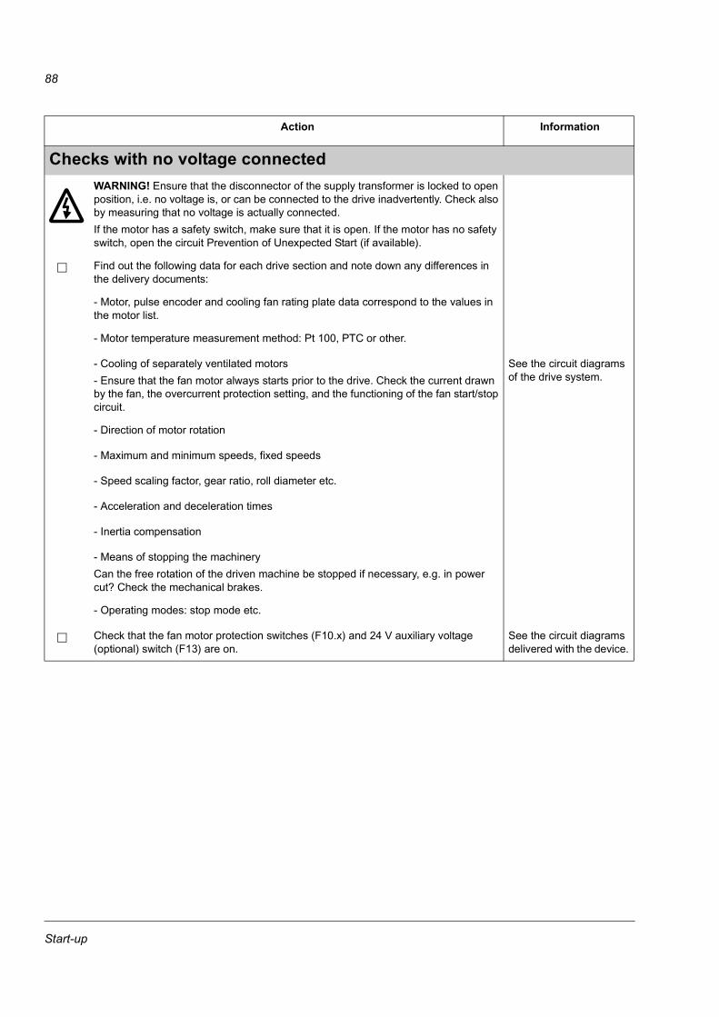
88
Action Information
Checks with no voltage connectedWARNING! Ensure that the disconnector of the supply transformer is locked to open position, i.e. no voltage is, or can be connected to the drive inadvertently. Check also by measuring that no voltage is actually connected.If the motor has a safety switch, make sure that it is open. If the motor has no safety switch, open the circuit Prevention of Unexpected Start (if available).
Find out the following data for each drive section and note down any differences in the delivery documents:
- Motor, pulse encoder and cooling fan rating plate data correspond to the values in the motor list.
- Motor temperature measurement method: Pt 100, PTC or other.
- Cooling of separately ventilated motors - Ensure that the fan motor always starts prior to the drive. Check the current drawn by the fan, the overcurrent protection setting, and the functioning of the fan start/stop circuit.
See the circuit diagrams of the drive system.
- Direction of motor rotation
- Maximum and minimum speeds, fixed speeds
- Speed scaling factor, gear ratio, roll diameter etc.
- Acceleration and deceleration times
- Inertia compensation
- Means of stopping the machineryCan the free rotation of the driven machine be stopped if necessary, e.g. in power cut? Check the mechanical brakes.
- Operating modes: stop mode etc.
Check that the fan motor protection switches (F10.x) and 24 V auxiliary voltage (optional) switch (F13) are on.
See the circuit diagrams delivered with the device.
Start-up

89
Connecting voltage to the driveThe possible supply disconnecting and switching options are shown below. See the circuit diagrams delivered with the unit for the actual connections (customized configurations).
WARNING! When the disconnecting device(s) of the Supply Section are closed, the voltage will also be connected to the Auxiliary Control Unit and to auxiliary circuits - also to the ones wired to drive sections. The DC busbars will become live, as will all the inverters connected to the DC busbars. The DC busbars will be powered to a voltage of 1.35⋅ U1.Make sure that it is safe to connect voltage to the Supply Section. Ensure that:- Nobody is working on the unit or circuits that are wired from outside into the cabinets.- It is safe to start the motor.- All cabinet doors are closed.
Disconnect the 230 VAC cables that lead from the terminal blocks to the outside of the equipment and have not yet been checked, and the connections which may not yet have been completed.
Disconnect the communication link to the overriding system by removing the fibre optic cables.
See the circuit diagrams delivered with the device.
Be ready to trip the main breaker of the supply transformer in case something abnormal occurs.
Ensure that all cabinet doors are closed.
Close the main breaker of the supply transformer.
Close the main disconnecting device of the Supply Section.
Close the main disconnecting switch of the auxiliary circuit (if present).
Close the main contactor/breaker of the Supply Unit.
Action Information
~=
~=
~=
Auxiliary voltage
L1, L2, L3
Switch fuse
~=
~=
~=
Auxiliary voltage
L1 L2 L3
~=
~=
~=
Auxiliary voltage
L1 L2 L3
Switch fuse and contactor Air circuit breaker
Start-up

90
Checks with voltage connected to drive sectionSet the drive parameters according to the application Firmware Manual.
Check that the Prevention of Unexpected Start (if available) is working:- Stop the drive by a Stop command and wait until the drive has stopped.- Open the Prevention of Unexpected Start switch by opening the switch on the control desk: the circuit will open. The lamp (if fitted) on the desk should be lit.- Give a Start command. The drive should not start.- Reset the drive.
See the circuit diagrams delivered with the device.
On-load checksCheck that the cooling air fans rotate freely in the right direction, and the air flows upwards.
A paper sheet set on the lower gratings stays. The fan runs noiselessly.
Check the rotation direction of the motor.
Check the pulse encoder functioning (if present) See Pulse Encoder Interface Module RTAC-0x Users Manual [3AFE 64486853 (english)].
Check the emergency stop function of the system from each operating place.
Checks of the overriding control link (if in use)Disconnect all voltages: open the main contactor/breaker (if present), open the main disconnecting device.
Connect the communication link to the overriding system by connecting the fibre optic cables.
See the circuit diagrams delivered with the device.
Power the unit up.
Check
- the start/stop functions
- speed/torque references
- alarm/fault words
- function in case of a communication break
- updating interval of the drive software
- other items essential to the application
Action Information
Start-up

91
Preventive maintenance
Chapter overviewThis chapter represents how to maintain the drive in operational condition.
WARNING! The Safety Instructions on the first pages of this manual must be followed. Negligence of these instructions can cause injury or death.
If installed in an appropriate environment, the drive requires very little maintenance.
An annual check-up for dust and corrosion accumulation on the surfaces inside the cabinet is recommended.
Air filtersWhen having filtering for cooling air, check and clean or replace filter mats if dirty. Wash dirty filter mats with water (60 °C) and detergent.
HeatsinkThe drive can run into overtemperature faults if the heatsink is not clean. In normal environment, the heatsink should be checked and cleaned annually.
Use compressed air to remove dust from the heatsink. (The airflow direction must be from bottom to top.) Also, use a vacuum cleaner at the air outlet to trap the dust. Fan rotation must be prevented in order to prevent bearing damage.
RelaysRelays should be checked for function and all connections should be inspected and checked for tightness. Any signs of corrosion, especially in ground components, shall be cleaned off.
FanThe cooling fan lifespan is approximately 40 000 hours. The actual lifespan depends on the frequency converter usage and ambient temperature.
Fan failure can be predicted by increasing noise from fan bearings and gradual rise in the heatsink temperature in spite of heatsink cleaning. If the frequency converter is used in a critical part of a process, fan replacement is recommended once these symptoms appear.
Preventive maintenance

92
Spare ModulesIf spare modules are available, it is recommended to replace the cabinet modules with their spare modules once a year in order to avoid capacitor reforming and to equalize wear and tear on the modules. See section Capacitors below.
CapacitorsThe drive intermediate circuit employs several electrolytic capacitors. The lifespan of the capacitors is approximately 100 000 hours, depending on the frequency converter loading and the ambient temperature.
Capacitor life can be prolonged by lowering the ambient temperature. It is not possible to predict capacitor failure.
Capacitor failure is usually followed by a mains fuse failure or a fault trip. Contact ABB if capacitor failure is suspected. Replacements are available from ABB. Do not attempt operation with other than ABB specified spare parts.
ReformingConverter DC link capacitors need to be reformed (re-aged) if the converter has been non-operational for more than one year. Without reforming capacitors may be damaged when the converter starts to operate. The reforming methods introduced here require that the converter has been stocked clean and dry. It is recommended to reform the capacitors once a year.
How to check the converter age
Converter serial number defines the week, when the converter has been built:
8 digit: e.g. 18250125, 1 denotes manufacturing country (1 = Finland), 8 manufacturing year (1998), 25 manufacturing week and 0125 running manufacturing number.
10 digit: e.g. 1983200725, 1 denotes manufacturing country, 98 manufacturing year, 32 manufacturing week and 00725 running manufacturing number.
Reforming time
The intermediate circuit of the converter is kept at its nominal voltage for the reforming time to wake up the capacitors. The reforming time required depends on how long the converter has been stocked (non-operational).
Preventive maintenance

93
Figure 1. Capacitor reforming time for Method 1 and Method 2.Converters Stocked (Non-operational) for Less Than 2 years
Switch the power on to the converter for a time given in Figure 1 (Method 1). The converter wakes up its capacitors by itself. Power the converters up once a year to keep the capacitors in operational condition.
Converters Stocked (Non-operational) for 2 Years and Over
Use Method 2 A or Method 2 B (both explained below) for capacitor reforming if the converter has been stocked or non-operational for two or more years.
Method 2 A
Capacitor reforming is realised by connecting a rectifier and a resistor circuit to the converter DC link. The reforming circuit and component values for different voltages are given below. See Figure 1 for reforming time.
WARNING! The converter supply must be disconnected while the reforming circuit is connected.
0 1 2 3 4 5 6
1
0
2
3
4
5
6
Non-operational time (years)
Reforming time (hours)
Method 1 Method 2
Preventive maintenance

94
* rectifier bridge by Semikron (82 A, 1600 V) or equivalent
Method 2 B
Capacitor reforming is based on a DC power supply connected to the converter DC link. Power supply current charges the converter capacitors. If power supply cannot limit the current, voltage is increased gradually (with e.g. 100 V steps). Maximum recommended reforming current is 500 mA. An appropriate reforming voltage is (1.35 ... √2) ⋅ U1. The reforming circuit is shown below. See Figure 1 for reforming time.
Supply Voltage Recommended Components
A* R C
380 V < U1 < 415 V SKD 82/16 220 Ohm / 700 W 22 nF / 2000 V
380 V < U1 < 500 V SKD 82/16 470 Ohm / 1200 W 22 nF / 2000 V
525 V < U1 < 690 V SKD 82/16 680 Ohm / 1700 W 22 nF / 2000 V
L L+
R
A
C
U1
Converter
or phase module
W2 (W1)
U2 (U1)V2 (V1)
Disconnect from supply (1.35 ⋅U1)
Preventive maintenance

95
WARNING! The converter supply must be disconnected while the reforming circuit is connected.
* R = 100 Ohm / 500 W
*
L L+
R
Converter
or phase module
W2 (W1)
U2 (U1)V2 (V1)
DC Power Supply
Disconnect from supply (1.35 ⋅U1)
Preventive maintenance

96
Preventive maintenance

97
Technical data
Chapter overviewThis chapter describes the technical data concerning ACS800-17 frequency converters.
RatingsThe ratings for the ACS800-17 with 50 Hz and 60 Hz supplies are given below.
Frequency converter typeDrive frame size
Normal use Duty cycle 1/5min Duty cycle 10/60sI2N
[A]
SN
[kVA]
PN
[kW]
I2hd4/5min
[A]
I2hd1/5min
[A]
I2hd50/60s
[A]
I2hd10/60s
[A]Supply voltage range 380, 400 or 415 VACS800-17-0120-3 R7i 178 120 90 147 221 147 294ACS800-17-0185-3 R8i 259 185 132 194 291 178 356ACS800-17-0225-3 R8i 312 225 160 234 351 216 432ACS800-17-0265-3 R8i 379 265 200 284 426 260 520ACS800-17-0335-3 R9i 474 335 250 356 533 316 632ACS800-17-0405-3 R9i 576 405 315 432 648 395 790ACS800-17-0630-3 R11i 907 630 500 680 1020 600 1200ACS800-17-0765-3 R11i 1094 765 630 821 1231 751 1502ACS800-17-0935-3 R12i 1336 935 710 1002 1503 901 1802ACS800-17-1125-3 R12i 1624 1125 900 1218 1827 1126 2252Supply voltage range 380, 400, 415, 440, 460, 480 or 500 VACS800-17-0100-5 R6i 112 100 75 84 126 84 168ACS800-17-0140-5 R7i 164 140 110 135 203 135 270ACS800-17-0215-5 R8i 246 215 160 185 277 164 328ACS800-17-0255-5 R8i 295 255 200 221 332 200 400ACS800-17-0325-5 R8i 368 325 250 276 414 240 480ACS800-17-0395-5 R9i 448 395 315 336 504 300 600ACS800-17-0495-5 R9i 565 495 400 424 636 365 730ACS800-17-0770-5 R11i 887 770 630 665 998 570 1140ACS800-17-0935-5 R11i 1073 935 710 805 1208 694 1388ACS800-17-1095-5 R12i 1263 1095 900 947 1421 855 1710ACS800-17-1385-5 R12i 1593 1385 1120 1195 1793 1040 2080Supply voltage range 525, 550, 575, 600, 660 or 690 VACS800-17-0120-6 R7i 105 120 90 88 132 88 176ACS800-17-0205-6 R8i 176 205 160 132 198 127 254ACS800-17-0255-6 R8i 210 255 200 158 236 150 300ACS800-17-0315-6 R8i 264 315 250 198 297 179 358ACS800-17-0375-6 R9i 310 375 315 233 349 225 450ACS800-17-0485-6 R9i 410 485 400 308 461 265 530ACS800-17-0750-6 R11i 630 750 630 473 709 428 856ACS800-17-0900-6 R11i 755 900 710 566 849 504 1008ACS800-17-1045-6 R12i 874 1045 800 656 983 641 1282ACS800-17-1385-6 R12i 1156 1385 1120 867 1301 755 1510
Technical data

98
The current ratings are the same regardless of the supply voltage within one voltage range. The rated current of the drive must be higher than or equal to the rated motor current to achieve the rated motor power given in the table.
Note 1: The load capacity (current and power) decreases if the installation site altitude exceeds 1000 metres, or if the ambient temperature exceeds 40 °C (units with degree of protection IP 21/22/42/54).
Note 2: Usually du/dt filters are needed at the output of 525 V to 690 V units with random wound motors. No du/dt filters are usually required with form wound motors.
Output current temperature derating The output current is calculated by multiplying the current given in the rating table by the derating factor.
Temperature derating factor for degree of protection IP 21/22/42/54:
General rule: Above +40 °C, the rated output current is decreased 1.5 % for every additional 1 °C (up to +50 °C).
Example 1: If the ambient temperature is 50 °C the derating factor is
100 % - 1.5 · 10 °C = 85 % or 0.85. The output current is then
0.85 · I2N or I2hd.
Derating Diagram: the effect of ambient temperature on the AC800-17 continuous load capacity.
Input power connectionVoltage (U1):380/400/415 VAC 3-phase ± 10 % for 400 VAC units380/400/415/440/460/480/500 VAC 3-phase ± 10 % for 500 VAC units525/550/575/600/660/690 VAC 3-phase ± 10 % for 690 VAC units
Normal Use Duty CycleI2N
SNPN
Rated rms output current (= maximum continuous output current)Rated apparent output powerTypical motor power. The power ratings in kW apply to most IEC 34 motors.
I2hd Rated rms output current
%°C
100
95
85
80
90
36 40
Current (%)
T (°C)44 48 52
-1.5 % per each + °CIP 21/22/42/54
IP 54R
Technical data

99
Short circuit capability IEC 439-1: The rated short time withstand current is given below
Frequency: 48 to 63 Hz, maximum rate of change 17 %/s
Input voltage unbalance: ± 3 % (EN 60204-1)
Power factor:cos ϕ1 = 1.00 (fundamental at nominal load)
λ = I1/Irms · cos ϕ1 > 0.98 (total), where
λ is power factor,
I1 is fundamental input current rms value,
Irms is total input current rms value.
Motor connectionVoltage (U2): 0 to U1, 3-phase symmetrical
Frequency: DTC mode: 0 to 3.2 · fFWP . Maximum frequency 300 Hz.
fFWP =
fFWP: Frequency at field weakening point; UNmains: Mains (input power) voltage; UNmotor: Rated motor voltage; fNmotor: Rated motor frequency
Scalar control mode: 0 to 300 Hz
With du/dt filter (DTC and Scalar Control modes): 0 to 120 Hz
Frequency resolution: 0.01 Hz
Continuous current:1.0 · I2N (normal use)
Short term overload capacity: According to rating tables on page 97.
Field weakening point: 8 to 300 Hz
Switching frequency: 3 kHz
Maximum recommended motor cable length: For cables longer than 500 metres / 1640 ft (cumulative length in case of parallel connected motors), an ABB representative must be consulted. With pulse encoder speed measurement, the maximum cable length is 300 m. With du/dt filters, refer to du/dt Filters Installation Guide [3AFE 58933368 (English)]. For additional EMC requirements on cable length, refer to section CE marking below.
Frame size I cw / 1 skA
I pk kA
ACS800-17: R8i, R9i 38 78
ACS800-17: R11i, R12i 50 105
UNmainsUNmotor
· fNmotor
Technical data

100
Motor bearings: Insulated bearing at the non-driven end is recommended.
Cable types: The tables below give the copper and aluminium cable types for different load currents (ILmax). A correction factor of K = 0.70 has been used (max. 9 cables laid on a cable ladder side by side, three ladders on top of each other, ambient temperature 30 °C (86 °F), EN 60204-1 and IEC 364-5-523)
Efficiency and cooling methodEfficiency: Approximately 96 %.
Cooling method: Internal fan, flow direction from the bottom to the top
COPPER CABLES WITHA CONCENTRIC COPPER SCREEN
ALUMINIUM CABLES WITHA CONCENTRIC COPPER SCREEN
ILmax[A]
Cable type Diameter[mm]
ILmax[A]
Cable type Diameter[mm]
255 3×185 + 95 50 260 2 × (3×95Al + 29Cu) 2 × 38274 2 × (3×70 + 35) 2 × 32 302 2 × (3×120Al + 41Cu) 2 × 41301 3×240 + 120 55 348 2 × (3×150Al + 41Cu) 2 × 44334 2 × (3×95 + 50) 2 × 38 398 2 × (3×185Al + 57Cu) 2 × 49386 2 × (3×120 + 70) 2 × 41 470 2 × (3×240Al + 72Cu) 2 × 54446 2 × (3×150 + 70) 2 × 44 522 3 × (3×150Al + 41Cu) 3 × 44510 2 × (3×185 + 95) 2 × 50 597 3 × (3×185Al + 57Cu) 3 × 49579 3 × (3×120 + 70) 3 × 41 696 4 × (3×150Al + 41Cu) 4 × 44602 2 × (3×240 + 120) 2 × 55 705 3 × (3×240Al + 72Cu) 3 × 54669 3 × (3×150 + 70) 3 × 44 796 4 × (3×185Al + 57Cu) 4 × 49765 3 × (3×185 + 95) 3 × 50 940 4 × (3×240Al + 72Cu) 4 × 54772 4 × (3×120 + 70) 4 × 41 995 5 × (3×185Al + 57Cu) 5 × 49892 4 × (3×150 + 70) 4 × 44 1175 5 × (3×240Al + 72Cu) 5 × 54903 3 × (3×240 + 120) 3 × 55
1020 4 × (3×185+ 95) 4 × 50
Technical data

101
Ambient conditionsEnvironmental limits of the frequency converters are given below. The frequency converters are to be used in a heated, indoor, controlled environment.
1) At sites over 1000 m (3300 ft.) above sea level, the maximum output current is derated as follows. If the installation site is higher than 2000 m (6600 ft.) above sea level, please contact your local ABB distributor or office for further information.
Imax = I N40C · (100 % - 1 % · (h - 1000 m)/(100 m) + 1.5 % · (40 °C - Tamb))
where
h altitude above sea level
I N40C drive nominal current at 40 °C
Tamb maximum ambient temperature.
Note: Imax < I N40C and Tamb < 40 °C. At 2000...4000 m optional varistors are needed.
2) See section Output current temperature derating.
Operation installed for stationary use
Storagein the protective package
Transportationin the protective package
Installation site altitude
Nominal output power at0 to 1000 m (3300 ft) above sea level 1)
- -
Air temperature 0 to +40 °C (32 to 104 °F) 2) (IP 21/22/42/54) 0 to +35 °C (32 to 95 °F) 2) (IP 54R)
-40 to +70 °C (-40 to +158 °F) -40 to +70 °C (-40 to +158 °F)
Relative humidity 5 to 95% Max. 95% Max. 95%No condensation allowed. Maximum allowed relative humidity is 60% in the presence of corrosive gases.
Contamination levels(IEC 721-3-3)
No conductive dust allowed.Boards without coating: Chemical gases: Class 3C1Solid particles: Class 3S2Boards with coating: Chemical gases: Class 3C2Solid particles: Class 3S2
Boards without coating: Chemical gases: Class 1C2Solid particles: Class 1S3Boards with coating: Chemical gases: Class 1C2Solid particles: Class 1S3
Boards without coating: Chemical gases: Class 2C2Solid particles: Class 2S2Boards with coating: Chemical gases: Class 2C2Solid particles: Class 2S2
Atmospheric pressure
70 to 106 kPa0.7 to 1.05 atmospheres
70 to 106 kPa0.7 to 1.05 atmospheres
60 to 106 kPa0.6 to 1.05 atmospheres
Vibration(IEC 68-2-6)
Max. 0.3 mm (0.01 in.)(2 to 9 Hz),max. 1 m/s2 (3.3 ft./s2)(9 to 200 Hz) sinusoidal
Max. 1.5 mm (0.06 in.)(2 to 9 Hz), max. 5 m/s2 (16.4 ft./s2)(9 to 200 Hz) sinusoidal
Max. 3.5 mm (0.14 in.)(2 to 9 Hz), max. 15 m/s2 (49 ft./s2)(9 to 200 Hz) sinusoidal
Shock(IEC 68-2-29)
Not allowed Max. 100 m/s2 (330 ft./s2), 11 ms
Max. 100 m/s2 (330 ft./s2), 11 ms
Free fall Not allowed 250 mm (10 in.) for weight under 100 kg (220 lbs.)100 mm (4 in.) for weight over 100 kg (220 lbs.)
250 mm (10 in.) for weight under 100 kg (220 lbs.)100 mm (4 in.) for weight over 100 kg (220 lbs.)
Technical data

102
FusesOnly ultra rapid fuses guarantee proper protection for the rectifier semiconductors.
AC fusesThe a.c. fuses (Bussmann) used in the ACS800-17 supply sections are listed below.
Frequency converter type
Frame size
Supply section type
Fuse
UNV
INA
Pre-arching integral
A2s
Type Size
Supply voltage 400V IGBT supplyACS800-17-0120-3 R7i - 690 350 10000 170M3818 DIN 43620 DIN1*ACS800-17-0185-3 R8i - 660 630 31000 170M6810 DIN3ACS800-17-0225-3 R8i - 660 630 31000 170M6810 DIN3ACS800-17-0265-3 R8i - 660 630 31000 170M6810 DIN3ACS800-17-0335-3 R9i - 660 1000 140000 170M6814 DIN3ACS800-17-0405-3 R9i - 660 1000 140000 170M6814 DIN3ACS800-17-0630-3 R11i ACA 635-0765-3 690 700 60500 170M5874 DIN 43653 2ACS800-17-0765-3 R11i ACA 635-0765-3 690 700 60500 170M5874 2ACS800-17-0935-3 R12i ACA 635-1125-3 690 900 125000 170M5876 2ACS800-17-1125-3 R12i ACA 635-1125-3 690 900 125000 170M5876 2Supply voltage 500V IGBT supplyACS800-17-0100-5 R6i - 660 200 2200 170M3815 DIN 43620 DIN1*ACS800-17-0140-5 R7i - 690 350 10000 170M3818 DIN1*ACS800-17-0215-5 R8i - 660 630 31000 170M6810 DIN1*ACS800-17-0255-5 R8i - 660 630 31000 170M6810 DIN1*ACS800-17-0325-5 R8i - 660 630 31000 170M6810 DIN1*ACS800-17-0395-5 R9i - 660 1000 140000 170M6814 DIN3ACS800-17-0495-5 R9i - 660 1000 140000 170M6814 DIN3ACS800-17-0770-5 R11i ACA 635-0935-5 690 700 60500 170M5874 DIN 43653 2ACS800-17-0935-5 R11i ACA 635-0935-5 690 700 60500 170M5874 2ACS800-17-1095-5 R12i ACA 635-1385-5 690 900 125000 170M5876 2ACS800-17-1385-5 R12i ACA 635-1385-5 690 900 125000 170M5876 2Supply voltage 690V IGBT supplyACS800-17-0120-6 R7i - 660 200 2200 170M3815 DIN 43620 DIN1ACS800-17-0205-6 R8i - 1250 400 19500 170M6303 3SHTACS800-17-0255-6 R8i - 1250 400 19500 170M6303 3SHTACS800-17-0315-6 R8i - 1250 400 19500 170M6303 3SHTACS800-17-0375-6 R9i - 1250 630 83500 170M6205 3SHTACS800-17-0485-6 R9i - 1250 630 83500 170M6205 3SHTACS800-17-0750-6 R11i ACA 635-0900-6 690 900 125000 170M5876 DIN 43653 2ACS800-17-0900-6 R11i ACA 635-0900-6 690 900 125000 170M5876 2ACS800-17-1095-6 R12i ACA 635-1385-6 690 700 60500 170M5874 2ACS800-17-1385-6 R12i ACA 635-1385-6 690 700 60500 170M5874 2
Technical data

103
Drive section DC fusesThe Bussmann fuses used in the inverters of the ACS800-17 are listed below. UN and IN are nominal voltage and current of the fuse.
Cable entries
Tightening torqueThe tightening torques for screw connections, applicable to zinc and chrome platings and screw strength class 8.8 are listed below.
* valid also for greased screws
MarkingCable connections are marked in the following tables as explained below. The terminals accept cable lugs according to DIN 46234 for copper cables and DIN 46329 for aluminium cables.
415 V and 500 V drive sections 690 V drive sectionsDrive Section Frame Size
UN[V]
IN[A]
Pre-arching integralA2s
Type Size Drive Section Frame Size
UN[V]
IN[A]
Pre-arching integralA2s
Type Size
2xR11i4xR11i2xR12i
660 1000 140000 170M6814 32xR11i4xR11i2xR12i
1250 630 83500 170M6205 3SHT
Screw Torque (Nm) *Soft aluminium Alloyed aluminium and copper
M5 3.5 3.5M6 6 9M8 17 20
M10 35 40M12 55 70M16 130 180
8x(13x18)Number of connection
Connection hole (or max. screw) diameter in mmholes in terminal
Note: Cable lugs can also be fastened using screws one size down from the hole size. Example: A cable lug with a hole diameter of 12.5 mm can be fastened with either a M12 or a M10 bolt.
Technical data

104
Connection holesThe connection holes for mains and motor cable lugs are given below.
* Isolated stud terminals for the motor cable:
maximum number of cable connections per phase: 1
cable cross section: 25...120 mm2 (3...250 MCM)
tightening torque: 30 Nm (265 lbf.in.).
Mains cable terminal: M10 bolt.
Frequency converter type
Frame size
Supply section type
Holes for cable lugs per phase
1)
Number of cable entries at bottom (diameter 60 mm)
mains/motor
Bottom plate opening
dimensions(mm)
Number of cable entries at top
(diameter 60 mm)
Supply voltage 400V IGBT supplyACS800-17-0120-3 R7i - * 3 75x239 3ACS800-17-0185-3 R8i - 4x(13x18) 6 75x239 6ACS800-17-0225-3 R8i - 4x(13x18) 6 75x239 6ACS800-17-0265-3 R8i - 4x(13x18) 6 75x239 6ACS800-17-0335-3 R9i - 4x(13x18) 6 75x239 6ACS800-17-0405-3 R9i - 4x(13x18) 6 75x239 6ACS800-17-0630-3 R11i ACA 635-0765-3 6x(13x18) 6/9 270x911 6ACS800-17-0765-3 R11i ACA 635-0765-3 6x(13x18) 6/9 270x911 6ACS800-17-0935-3 R12i ACA 635-1125-3 8x(13x18) 12 195x501 12ACS800-17-1125-3 R12i ACA 635-1125-3 8x(13x18) 12 195x501 12Supply voltage 500V IGBT supplyACS800-17-0100-5 R6i - * 3 75x239 3ACS800-17-0140-5 R7i - * 3 75x239 3ACS800-17-0215-5 R8i - 4x(13x18) 6 75x239 6ACS800-17-0255-5 R8i - 4x(13x18) 6 75x239 6ACS800-17-0325-5 R8i - 4x(13x18) 6 75x239 6ACS800-17-0395-5 R9i - 4x(13x18) 6 75x239 6ACS800-17-0495-5 R9i - 4x(13x18) 6 75x239 6ACS800-17-0770-5 R11i ACA 635-0935-5 6x(13x18) 6/9 270x911 6ACS800-17-0935-5 R11i ACA 635-0935-5 6x(13x18) 6/9 270x911 6ACS800-17-1095-5 R12i ACA 635-1385-5 8x(13x18) 6/12 270x911 6ACS800-17-1385-5 R12i ACA 635-1385-5 8x(13x18) 6/12 270x911 6Supply voltage 690V IGBT supplyACS800-17-0120-6 R7i - * 3 75x239 3ACS800-17-0205-6 R8i - 4x(13x18) 6 75x239 6ACS800-17-0255-6 R8i - 4x(13x18) 6 75x239 6ACS800-17-0315-6 R8i - 4x(13x18) 6 75x239 6ACS800-17-0375-6 R9i - 4x(13x18) 6 75x239 6ACS800-17-0485-6 R9i - 4x(13x18) 6 75x239 6ACS800-17-0750-6 R11i ACA 635-0900-6 6x(13x18) 6/9 270x911 6ACS800-17-0900-6 R11i ACA 635-0900-6 6x(13x18) 6/9 270x911 6ACS800-17-1095-6 R12i ACA 635-1385-6 8x(13x18) 12 195x501 12ACS800-17-1385-6 R12i ACA 635-1385-6 8x(13x18) 12 195x501 12
Technical data

105
Drive sectionsThe connection holes for motor cable lugs (terminals U2, V2 and W2) are presented below.
1) The number of holes when common output cubicle is used for common motor cable connection or top exit is as follows:
Type Frame sizeHoles for cable lugs per phase
1)
Number of cable entries at
bottom (diameter 60 mm)
Bottom plate opening
dimensions(mm)
Number of cable entries at top
(diameter 60 mm)
380V, 400V, 415VACS800-17-0760-3 R11i 6x(13x18) 9 270x911 9ACS800-17-0930-3 R12i 8x(13x18) 12 195x501 12ACS800-17-1120-3 R12i 8x(13x18) 12 195x501 12ACS800-17-1440-3 2xR11i 2x6x(13x18) 2x9 270x711 9ACS800-17-1770-3 2xR12i 2x8x(13x18) 2x12 270x711 18ACS800-17-2140-3 2xR12i 2x8x(13x18) 2x12 270x711 18ACS800-17-2340-3 4xR11i 4x6x(13x18) 4x9 270x711 18ACS800-17-2820-3 4xR11i 4x6x(13x18) 4x9 270x711 18440V, 460V, 500VACS800-17-0930-5 R11i 6x(13x18) 9 270x911 9ACS800-17-1090-5 R12i 8x(13x18) 12 195x501 12ACS800-17-1380-5 R12i 8x(13x18) 12 195x501 12ACS800-17-1760-5 2xR11i 2x6x(13x18) 2x9 270x711 9ACS800-17-2160-5 2xR12i 2x8x(13x18) 2x12 270x711 18ACS800-17-2620-5 2xR12i 2x8x(13x18) 2x12 270x711 18ACS800-17-2850-5 4xR11i 4x6x(13x18) 4x9 270x711 18ACS800-17-3450-5 4xR11i 4x6x(13x18) 4x9 270x711 18575V, 660V, 690VACS800-17-0900-6 R11i 6x(13x18) 9 270x911 6ACS800-17-1040-6 R12i 8x(13x18) 12 195x501 12ACS800-17-1380-6 R12i 8x(13x18) 12 195x501 12ACS800-17-1710-6 2xR11i 2x6x(13x18) 2x9 270x711 9ACS800-17-2120-6 2xR12i 2x8x(13x18) 2x12 270x711 18ACS800-17-2540-6 2xR12i 2x8x(13x18) 2x12 270x711 18ACS800-17-2800-6 4xR11i 4x6x(13x18) 4x9 270x711 18ACS800-17-3350-6 4xR11i 4x6x(13x18) 4x9 270x711 18
Frame size Number of holes per phase
R11i, R12i 82xR11i, 2xR12i 104xR11i 2x8
Technical data

106
CabinetBelow are the cabinets, degrees of protection and free space requirements.
1) IP 21 = standard, R = air outlet duct2) 200 between cabinets when installed back to back
Degree of Protection
Spaceabove mm
Spacebelow mm
Space onleft/right mm
Space infront/back mm
IP 21, IP 22, IP 42, IP 54, IP 54 R1)
500 0 0200/100
2)
Door opening
Technical data

107
Drive section hardwareThe frequency converter types contain inverters given below.
Frequency converter type Inverter Drive frame sizeSupply voltage 380, 400 or 415VACS800-17-0100-3 ACN 634 0100 3 R7iACS800-17-0120-3 ACN 634 0120 3 R7iACS800-17-0185-3 ACN 634-0185-3 R8iACS800-17-0225-3 ACN 634-0225-3 R8iACS800-17-0265-3 ACN 634-0265-3 R8iACS800-17-0335-3 ACN 634-0335-3 R9iACS800-17-0405-3 ACN 634-0405-3 R9iACS800-17-0630-3 ACN 634-0635-3 R11iACS800-17-0765-3 ACN 634-0755-3 R11iACS800-17-0935-3 ACN 634-0935-3 R12iACS800-17-1125-3 ACN 634-1125-3 R12iSupply voltage 380, 400, 415, 440, 460, 480 or 500VACS800-17-0120-5 ACN 634 0120 5 R7iACS800-17-0140-5 ACN 634 0140 5 R7iACS800-17-0215-5 ACN 634-0215-5 R8iACS800-17-0255-5 ACN 634-0255-5 R8iACS800-17-0325-5 ACN 634-0325-5 R8iACS800-17-0395-5 ACN 634-0395-5 R9iACS800-17-0495-5 ACN 634-0495-5 R9iACS800-17-0770-5 ACN 634-0775-5 R11iACS800-17-0935-5 ACN 634-0925-5 R11iACS800-17-1095-5 ACN 634-1095-5 R12iACS800-17-1385-5 ACN 634-1385-5 R12iSupply voltage 525, 550, 575, 600, 660 or 690VACS800-17-0100-6 ACN 634 0100 6 R7iACS800-17-0120-6 ACN 634 0120 6 R7iACS800-17-0205-6 ACN 634-0205-6 R8iACS800-17-0255-6 ACN 634-0255-6 R8iACS800-17-0315-6 ACN 634-0315-6 R8iACS800-17-0375-6 ACN 634-0375-6 R9iACS800-17-0485-6 ACN 634-0485-6 R9iACS800-17-0750-6 ACN 634-0755-6 R11iACS800-17-0900-6 ACN 634-0905-6 R11iACS800-17-1045-6 ACN 634-1045-6 R12iACS800-17-1385-6 ACN 634-1385-6 R12i
PDM code 00001161 REV C
Technical data

108
Cooling air, dimensionsThis table gives the depth of the cabinet. The height of the switch fuse handle is 45 mm from the cabinet door.
This table gives the height of the cabinet.
Depth mmDepth of the frame 600Depth of the roof 644Depth including the door, the frame and the back plate 637Depth including the door, the frame, the back plate and the flash barrier
678
Added depth including air circuit breaker spacer frame and door frame (measured from door)
60
Added depth of air circuit breaker spacer frame, door frame and transparent cover (measured from door)
178
Added depth of switch fuse (measured from door) 45
Height mmHeight of the cabinet with a double lifted roof 2121Height of the ACS800-17 cabinet (IP 21) 2062Height of the IP 54R cabinet 2072
Technical data

109
Air flow requirementsBelow are cooling air flow requirements, heat losses, dimensions and weights of ACS800-17.
1)With cable top entry/exit additional 200 mm is required in frame sizes R11i and R12i.
Frequency converter type
IGBT supply Drive section Air flow[m3/h]
Heat loss[kW]
Width 1)
[mm]Weight
[kg]Framesize Section type Module type Frame
size Module type
Supply voltage 400V IGBT supplyACS800-17-0120-3 R7i - ACN634-0120-3 R7i ACN634-0120-3 1920 4.1 730 305ACS800-17-0185-3 R8i - ACN634-0185-3 R8i ACN634-0265-3 3650 6.0 1200 625ACS800-17-0225-3 R8i - ACN634-0225-3 R8i ACN634-0265-3 3650 7.3 1200 625ACS800-17-0265-3 R8i - ACN634-0265-3 R8i ACN634-0265-3 3650 8.9 1200 625ACS800-17-0335-3 R9i - ACN634-0335-3 R9i ACN634-0405-3 3650 11.2 1200 655ACS800-17-0405-3 R9i - ACN634-0405-3 R9i ACN634-0405-3 3650 13.9 1200 655ACS800-17-0630-3 R11i ACA 635-0765-3 ACN634-0635-3 R11i ACN634-0765-3 7280 22.0 3600 1490ACS800-17-0765-3 R11i ACA 635-0755-3 ACN634-0755-3 R11i ACN634-0755-3 7280 27.2 3600 1490ACS800-17-0935-3 R12i ACA 635-1125-3 ACN634-0935-3 R12i ACN634-1125-3 10330 31.7 4600 2530ACS800-17-1125-3 R12i ACA 635-1125-3 ACN634-1125-3 R12i ACN634-1125-3 10330 39.3 4600 2530Supply voltage 500V IGBT supplyACS800-17-0100-5 R6i - ACN 634-0140-5 R6i ACN634-0100-5 1920 3.4 730 305ACS800-17-0140-5 R7i - ACN 634-0140-5 R7i ACN634-0140-5 1920 4.9 730 305ACS800-17-0215-5 R8i - ACN 634-0325-5 R8i ACN634-0325-5 3650 7.2 1200 625ACS800-17-0255-5 R8i - ACN 634-0325-5 R8i ACN634-0325-5 3650 8.8 1200 625ACS800-17-0325-5 R8i - ACN 634-0325-5 R8i ACN634-0325-5 3650 11.1 1200 625ACS800-17-0395-5 R9i - ACN 634-0495-5 R9i ACN634-0495-5 3650 13.7 1200 655ACS800-17-0495-5 R9i - ACN 634-0495-5 R9i ACN634-0495-5 3650 17.4 1200 655ACS800-17-0770-5 R11i ACA 635-0935-5 ACN 634-0925-5 R11i ACN634-0775-5 7280 27.3 3600 1490ACS800-17-0935-5 R11i ACA 635-0935-5 ACN 634-0925-5 R11i ACN634-0775-5 7280 31.7 3600 1490ACS800-17-1090-5 R12i ACA 635-1385-5 ACN 634-1385-5 R12i ACN634-1385-5 10330 38.9 4600 2530ACS800-17-1385-5 R12i ACA 635-1385-5 ACN 634-1385-5 R12i ACN634-1385-5 10330 48.7 4600 2530Supply voltage 690V IGBTsupplyACS800-17-0120-6 R7i - ACN 634-0120-6 R7i ACN634-0120-6 1920 4.1 730 305ACS800-17-0205-6 R8i - ACN 634-0315-6 R8i ACN634-0315-6 3650 7.2 1200 625ACS800-17-0255-6 R8i - ACN 634-0315-6 R8i ACN634-0315-6 3650 8.8 1200 625ACS800-17-0315-6 R8i - ACN 634-0315-6 R8i ACN634-0315-6 3650 10.9 1200 625ACS800-17-0375-6 R9i - ACN 634-0485-6 R9i ACN634-0485-6 3650 13.4 1200 655ACS800-17-0485-6 R9i - ACN 634-0485-6 R9i ACN634-0485-6 3650 17.2 1200 655ACS800-17-0750-6 R11i ACA 635-0900-6 ACN 634-0905-6 R11i ACN634-0905-6 7280 27.0 3600 1730ACS800-17-0900-6 R11i ACA 635-0900-6 ACN 634-0905-6 R11i ACN634-0905-6 7280 31.3 3600 1730ACS800-17-1045-6 R12i ACA 635-1385-6 ACN 634-1385-6 R12i ACN634-1385-6 10330 38.1 4600 2530ACS800-17-1385-6 R12i ACA 635-1385-6 ACN 634-1385-6 R12i ACN634-1385-6 10330 48.7 4600 2530
PDM code 00145936 F
Technical data

110
NoiseThe noise values of the ACS800-17 units are given below.
Applicable standardsThe drive complies with the following standards:
EN 60204-1: 1992 + Corr. 1993 (IEC 60204-1). Safety of machinery. Electrical equipment of machines. Part 1: General requirements. Provisions for compliance: The final assembler of the machine is responsible for installing - an emergency-stop device.
EN 60529: 1991 (IEC 60529), IEC 60664-1: 1992. Degrees of protection provided by enclosures (IP code).
EN 50178: 1986. Electronic equipment for use in power installations.
EN 61800-3:1996 (IEC 61800-3): EMC product standard including specific test methods.
Materials
Type Noise (dB) Type Noise
(dB) Type Noise (dB)
ACS800-17-0120-3 63 ACS800-17-0100-5 63 ACS800-17-0120-6 63ACS800-17-0185-3 63 ACS800-17-0140-5 63 ACS800-17-0205-6 63ACS800-17-0225-3 63 ACS800-17-0215-5 63 ACS800-17-0255-6 63ACS800-17-0265-3 63 ACS800-17-0255-5 63 ACS800-17-0315-6 63ACS800-17-0335-3 63 ACS800-17-0325-5 63 ACS800-17-0375-6 63ACS800-17-0405-3 63 ACS800-17-0395-5 63 ACS800-17-0485-6 63ACS800-17-0630-3 68 ACS800-17-0495-5 63 ACS800-17-0750-6 68ACS800-17-0765-3 68 ACS800-17-0770-5 68 ACS800-17-0900-6 68ACS800-17-0935-3 71 ACS800-17-0935-5 68 ACS800-17-1045-6 71ACS800-17-1125-3 71 ACS800-17-1090-5 71 ACS800-17-1385-6 71
ACS800-17-1385-5 71
Enclosure Coating thickness
Colour
hot-dip zinc coated steel sheet 1.0 to 2.5 mm with polyester thermosetting powder coating in visible surfaces
60 µm RAL 7035 light beige semigloss
Flat busbarsaluminium (standard), copper (optional), tin plated copper (optional)Packagewood or plywood (seaworthy package). Plastic covering of the package: PE-LD, bands PP or steel.
Technical data

111
TransportationLength: max. 4 metres, weight max. 2400 kg
Position: upright
Max. crate dimensions:length shipping length + 100 mm
depth shipping split depth + 150 mm
height cabinet height + 80 mm
Max. seaworthy dimensions:length shipping length + 200 mm
depth shipping split depth + 185 mm
height 2200 mm
DisposalThe drive contains raw materials that should be recycled to preserve energy and natural resources. The packing materials of the drive units and options are environmentally compatible and recyclable. All metal parts can be recycled. The plastic parts can either be recycled or burned under controlled circumstances, according to local regulations. If recycling is not feasible, all parts excluding electrolytic capacitors can be landfilled. The DC capacitors of the unit contain electrolyte which is classified as hazardous waste. They must be removed and handled according to local regulations.
For further information on environmental aspects, please contact your local ABB distributor.
CE markingA CE mark is attached to ACS800-17 drives to verify that the unit follows the provisions of the European Low Voltage and EMC Directives (Directive 73/23/EEC, as amended by 93/68/EEC and Directive 89/336/EEC, as amended by 93/68/EEC).
DefinitionsEMC stands for Electromagnetic Compatibility. It is the ability of electrical/electronic equipment to operate without problems within an electromagnetic environment. Likewise, the equipment must not disturb or interfere with any other product or system within its locality.
The EMC Directive defines the requirements for immunity and emissions of electrical equipment used within the European Union. The EMC product standard EN 61800-3 covers requirements stated for drives.
First environment includes establishments connected to a low-voltage network which supplies buildings used for domestic purposes.
Technical data

112
Second environment includes establishments connected to a network not supplying domestic premises.
Restricted distribution: mode of sales distribution in which the manufacturer restricts the supply of equipment to suppliers, customers or users who separately or jointly have technical competence in the EMC requirements of the application of drives.
Unrestricted distribution: mode of sales distribution in which the supply of equipment is not dependent on the EMC competence of the customer or user for the application of drives.
Machinery directiveThe drives comply with the European Union Machinery Directive (98/392/EEC) requirements for an equipment intended to be incorporated into machinery.
Compliance with IEC 61800-3ACS800-17 drives comply with the limits of IEC 61800-3 with the following provisions:
Second Environment
It is ensured that no excessive emission is propagated to neighbouring low-voltage networks. In some cases, the natural suppression in transformers and cables is sufficient. If in doubt, the use of EMC filters (if available) or any type of the output filters (du/dt, sine or common mode filter) and/or supply transformers with static screening between the primary and secondary windings is strongly recommended.
The motor and control cables are selected as specified in the Hardware Manual
The drive is installed according to the instructions given in the Hardware Manual.
Notes: The ACS800-17 must not be equipped with EMC filtering independent on network earthing.
Low voltage
Equipment
Low voltage
Equipment
Equipment(victim)
Supply transformer
Medium voltage network
Static screen
Point of measurement
Drive
Neighbouring network
Technical data

113
CSA markingThe CSA marking is often required in North America. CSA marked ACS800-17 drives are available on request up to 600 V.
The drive is suitable for use in a circuit capable of delivering not more than 65 kA rms symmetrical amperes at 600 V maximum.
The drive provides overload protection in accordance with the CSA standard C22.2 No 14 and the National Electrical Code (US). See ACS 800 Firmware Manual for the parameter setting. The setting is OFF by default; it must be activated at start-up.
The drive is to be used in a heated indoor controlled environment. See section Ambient conditions for specific limits.
C-tick marking C-tick marking is required in Australia and New Zealand.
A C-tick mark is attached to each drive in order to verify compliance with the relevant standard (IEC 61800-3 (1996) Adjustable speed electrical power drive systems Part 3: EMC product standard including specific test methods), mandated by the Trans-Tasman Electromagnetic Compatibility Scheme.
DefinitionsEMC stands for Electromagnetic Compatibility. It is the ability of electrical/electronic equipment to operate without problems within an electromagnetic environment. Likewise, the equipment must not disturb or interfere with any other product or system within its locality.
The Trans-Tasman Electromagnetic Compatibility Scheme (EMCS) was introduced by the Australian Communication Authority (ACA) and the Radio Spectrum Management Group (RSM) of the New Zealand Ministry of Economic Development (NZMED) in November 2001. The aim of the scheme is to protect the radiofrequency spectrum by introducing technical limits for emission from electrical/electronic products.
Second environment includes establishments connected to a network not supplying domestic premises.
Restricted distribution: mode of sales distribution in which the manufacturer restricts the supply of equipment to suppliers, customers or users who separately or jointly have technical competence in the EMC requirements of the application of drives.
Unrestricted distribution: mode of sales distribution in which the supply of equipment is not dependent on the EMC competence of the customer or user for the application of drives.
Technical data

114
Equipment warranty and liabilityGeneral: ABB warrants the Equipment supplied by ABB against defects in material and workmanship for a period of twelve (12) months after installation or twenty four (24) months from date of shipment from factory, whichever first occurs.
Should any failure to conform with the applicable warranties appear during the specified periods under normal and proper use and provided the Equipment has been properly stored, installed, operated and maintained, and if given prompt notice by Purchaser, ABB shall correct such nonconformity, at its option; by (1) repair or replacement of the nonconforming equipment or parts thereof. Repairs or replacements pursuant to warranty shall not renew or extend the applicable original equipment warranty period, provided however, that any such repairs or replacement of equipment or parts thereof shall be warranted for the time remaining of the original warranty period or 30 days, whichever is longer.
ABB shall not be responsible for providing working access to the defect, including disassembly and reassembly of equipment or for providing transportation to and from repair or factory facility, all of which shall be at Purchasers risk and expense.
These warranties shall not apply to any Equipment or parts thereof which (1) have been improperly repaired or altered; (2) have been subjected to misuse, negligence or accident; (3) have been used in a manner contrary to ABBs instructions; (4) are comprised of materials provided or designed stipulated by Purchaser; or (5) are used equipment.
The foregoing warranties are exclusive and in lieu of all other warranties of quality and performance, written, oral or implied, and all other warranties including any implied warranties of merchantability or fitness for a particular purpose are hereby disclaimed by ABB and all equipment manufacturers.
Correction of nonconformities in the manner and for the period of time provided above shall be the Purchasers exclusive remedy and shall constitute fulfilment of all liabilities of ABB and any Equipment manufacturer (including any liability for direct, indirect, special, incidental or consequential damages) whether in warranty, contract, negligence, tort, strict liability, or otherwise with respect to any nonconformance of or defect or deficiency in the equipment supplied or services furnished hereunder.
Technical data

115
Limitation of liabilityIN NO EVENT SHALL ABB, ITS SUPPLIERS OR SUBCONTRACTORS BE LIABLE FOR SPECIAL, INDIRECT, INCIDENTAL OR CONSEQUENTIAL DAMAGES, WHETHER IN CONTRACT, WARRANTY, TORT, NEGLIGENCE, STRICT LIABILITY OR OTHERWISE, including, but not limited to loss of profits or revenue, loss of use of the Equipment or any associated equipment, cost of capital, cost of substitute equipment, facilities or services, downtime costs, delays, or claims of customers of the Purchaser or other third parties for such or other damages. ABBs liability on any claim whether in contract, warranty, negligence, tort, strict liability, or otherwise for any loss or damage arising out of, connected with, or resulting from the contract or the performance or breach thereof, or from the design, manufacture, sale, delivery, resale, repair, replacement, installation, technical direction of installation, inspection, operation or use of any equipment covered by or in connection therewith, shall in no case exceed the purchase price of the Equipment or part thereof or services which give rise to the Claim.
All clauses of action against ABB arising out of or relating to the contract or the performance or breach hereof shall expire unless brought within one year of the time of accrual thereof.
In no event, regardless of cause, shall ABB assume responsibility for or be liable for penalties or penalty clauses of any description or for indemnification of customer or others for costs, damages, or expenses each arising out of or related to the goods or services of the order.
Your local distributor or ABB office may hold different guarantee details, which are specified in the sales terms, conditions, or guarantee terms. These terms are available on request.
If you have any questions concerning your ABB frequency converter, please contact the local distributor or ABB office. The technical data, information and specifications are valid at the time of printing. The manufacturer reserves the right to modifications without prior notice.
Technical data

116
Technical data

117
Dimensional drawings
Chapter overviewThis chapter contains the dimensional drawings of ACS800-17 frame sizes R6i to R12i.
Dimensional drawings
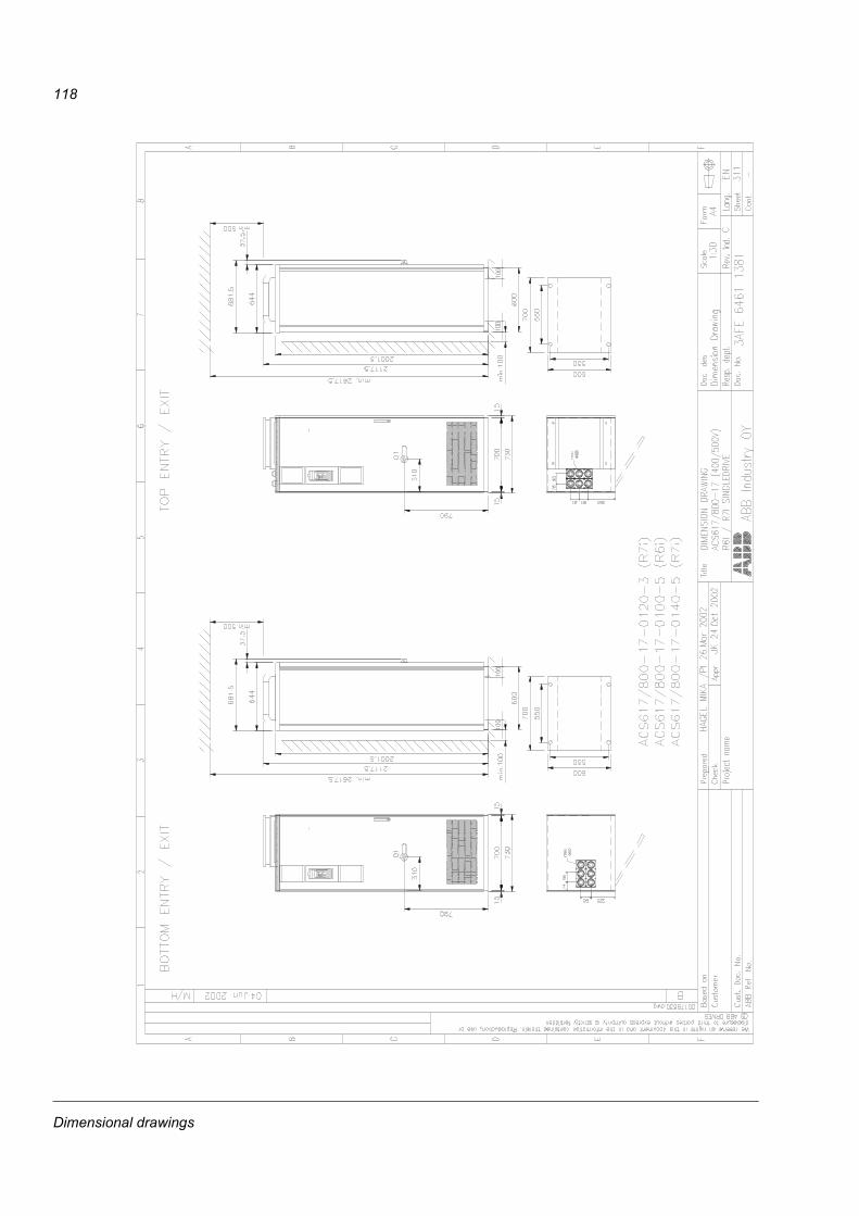
118
Dimensional drawings

119
Dimensional drawings

120
Dimensional drawings

121
Dimensional drawings

122
Dimensional drawings


ABB OyAC DrivesP.O. Box 184FIN-00381 HELSINKIFINLANDTelephone +358 10 22 11Telefax +358 10 22 22681Internet http://www.abb.com
ABB Inc.Drives and Power Electronics16250 West Glendale DriveNew Berlin, WI 53151USATelephone 262 785-3200
800 243-4384Telefax 262 780-5135
3AFE
646
8133
8 R
ev A
/ EN
EFFE
CTI
VE: 0
1.11
.200
2