Embed Size (px)
Citation preview

ETSI EN 300 225 V1.5.1 (2015-12)
Electromagnetic compatibility and Radio spectrum Matters (ERM);
Technical characteristics and methods of measurement for survival craft portable VHF
radiotelephone apparatus
EUROPEAN STANDARD

ETSI
ETSI EN 300 225 V1.5.1 (2015-12) 2
Reference REN/ERM-TG26-515
Keywords GMDSS, maritime, radio, VHF
ETSI
650 Route des Lucioles F-06921 Sophia Antipolis Cedex - FRANCE
Tel.: +33 4 92 94 42 00 Fax: +33 4 93 65 47 16
Siret N° 348 623 562 00017 - NAF 742 C
Association à but non lucratif enregistrée à la Sous-Préfecture de Grasse (06) N° 7803/88
Important notice
The present document can be downloaded from: http://www.etsi.org/standards-search
The present document may be made available in electronic versions and/or in print. The content of any electronic and/or print versions of the present document shall not be modified without the prior written authorization of ETSI. In case of any
existing or perceived difference in contents between such versions and/or in print, the only prevailing document is the print of the Portable Document Format (PDF) version kept on a specific network drive within ETSI Secretariat.
Users of the present document should be aware that the document may be subject to revision or change of status. Information on the current status of this and other ETSI documents is available at
http://portal.etsi.org/tb/status/status.asp
If you find errors in the present document, please send your comment to one of the following services: https://portal.etsi.org/People/CommiteeSupportStaff.aspx
Copyright Notification
No part may be reproduced or utilized in any form or by any means, electronic or mechanical, including photocopying and microfilm except as authorized by written permission of ETSI.
The content of the PDF version shall not be modified without the written authorization of ETSI. The copyright and the foregoing restriction extend to reproduction in all media.
© European Telecommunications Standards Institute 2015.
All rights reserved.
DECTTM, PLUGTESTSTM, UMTSTM and the ETSI logo are Trade Marks of ETSI registered for the benefit of its Members. 3GPPTM and LTE™ are Trade Marks of ETSI registered for the benefit of its Members and
of the 3GPP Organizational Partners. GSM® and the GSM logo are Trade Marks registered and owned by the GSM Association.

ETSI
ETSI EN 300 225 V1.5.1 (2015-12) 3
Contents Intellectual Property Rights ................................................................................................................................ 7
Foreword ............................................................................................................................................................. 7
Modal verbs terminology .................................................................................................................................... 7
1 Scope ........................................................................................................................................................ 8
2 References ................................................................................................................................................ 8
2.1 Normative references ......................................................................................................................................... 8
2.2 Informative references ........................................................................................................................................ 8
3 Definitions and abbreviations ................................................................................................................... 9
3.1 Definitions .......................................................................................................................................................... 9
3.2 Abbreviations ..................................................................................................................................................... 9
4 General requirements ............................................................................................................................... 9
4.1 Construction ....................................................................................................................................................... 9
4.2 Frequencies and power ..................................................................................................................................... 10
4.3 Controls ............................................................................................................................................................ 10
4.4 Switching time .................................................................................................................................................. 10
4.5 Safety precautions ............................................................................................................................................ 11
4.6 Class of emission and modulation characteristics ............................................................................................ 11
4.7 Battery .............................................................................................................................................................. 11
4.8 Labelling........................................................................................................................................................... 11
5 Test conditions, power sources and ambient temperatures .................................................................... 12
5.1 Normal and extreme test conditions ................................................................................................................. 12
5.2 Test power source ............................................................................................................................................. 12
5.3 Normal test conditions ...................................................................................................................................... 12
5.3.1 Normal temperature and humidity .............................................................................................................. 12
5.3.2 Normal power source .................................................................................................................................. 12
5.4 Extreme test conditions .................................................................................................................................... 12
5.4.1 Extreme temperatures ................................................................................................................................. 12
5.4.1.1 Upper extreme temperature ................................................................................................................... 12
5.4.1.2 Lower extreme temperature .................................................................................................................. 12
5.4.2 Extreme test power supply values ............................................................................................................... 12
5.4.2.1 Upper extreme test voltage .................................................................................................................... 12
5.4.2.2 Lower extreme test voltage ................................................................................................................... 13
5.5 Procedure for tests at extreme temperatures ..................................................................................................... 13
6 General conditions of measurement ....................................................................................................... 13
6.1 Test connections ............................................................................................................................................... 13
6.2 Arrangements for test signals applied to the receiver input .............................................................................. 13
6.3 Receiver mute or squelch facility ..................................................................................................................... 13
6.4 Normal test modulation .................................................................................................................................... 13
6.5 Artificial antenna .............................................................................................................................................. 14
6.6 Test channels .................................................................................................................................................... 14
6.7 Measurement uncertainty and interpretation of the measuring results ............................................................. 14
6.7.1 Measurement uncertainty ............................................................................................................................ 14
6.7.2 Interpretation of the measurement results ................................................................................................... 14
7 Environmental tests ................................................................................................................................ 15
7.1 Introduction ...................................................................................................................................................... 15
7.2 Procedure .......................................................................................................................................................... 15
7.3 Performance check ........................................................................................................................................... 15
7.4 Drop test on hard surface .................................................................................................................................. 15
7.4.1 Definition .................................................................................................................................................... 15
7.4.2 Method of measurement ............................................................................................................................. 15
7.4.3 Requirement ................................................................................................................................................ 15
7.5 Vibration test .................................................................................................................................................... 16
7.5.1 Method of measurement ............................................................................................................................. 16

ETSI
ETSI EN 300 225 V1.5.1 (2015-12) 4
7.5.2 Requirement ................................................................................................................................................ 16
7.6 Temperature tests ............................................................................................................................................. 16
7.6.1 General ........................................................................................................................................................ 16
7.6.2 Dry heat cycle ............................................................................................................................................. 16
7.6.2.1 Method of measurement ........................................................................................................................ 16
7.6.2.2 Requirement .......................................................................................................................................... 16
7.6.3 Damp heat cycle ......................................................................................................................................... 17
7.6.3.1 Method of measurement ........................................................................................................................ 17
7.6.3.2 Requirement .......................................................................................................................................... 17
7.6.4 Low temperature cycle ................................................................................................................................ 17
7.6.4.1 Method of measurement ........................................................................................................................ 17
7.6.4.2 Requirement .......................................................................................................................................... 17
7.7 Corrosion test (sea water test) .......................................................................................................................... 17
7.7.1 General ........................................................................................................................................................ 17
7.7.2 Method of measurement ............................................................................................................................. 18
7.7.3 Requirements .............................................................................................................................................. 18
7.8 Immersion test .................................................................................................................................................. 18
7.8.1 Method of measurement ............................................................................................................................. 18
7.8.2 Requirements .............................................................................................................................................. 19
7.9 Thermal shock .................................................................................................................................................. 19
7.9.1 Method of measurement ............................................................................................................................. 19
7.9.2 Requirements .............................................................................................................................................. 19
7.10 Solar radiation .................................................................................................................................................. 19
7.10.1 Method of measurement ............................................................................................................................. 19
7.10.2 Requirements .............................................................................................................................................. 19
7.11 Oil resistance test.............................................................................................................................................. 19
7.11.1 Method of measurement ............................................................................................................................. 19
7.11.2 Requirement ................................................................................................................................................ 20
8 Field measurement ................................................................................................................................. 20
8.1 General ............................................................................................................................................................. 20
8.2 Transmitter Effective Radiated Power (ERP)................................................................................................... 20
8.2.1 Definition .................................................................................................................................................... 20
8.2.2 Method of measurement ............................................................................................................................. 20
8.2.3 Limit ........................................................................................................................................................... 21
8.3 Spurious emissions from the transmitter .......................................................................................................... 21
8.3.1 Definition .................................................................................................................................................... 21
8.3.2 Method of measurement ............................................................................................................................. 21
8.3.3 Limit ........................................................................................................................................................... 21
8.4 Spurious emissions from the receiver ............................................................................................................... 21
8.4.1 Definition .................................................................................................................................................... 21
8.4.2 Method of measurement ............................................................................................................................. 21
8.4.3 Limit ........................................................................................................................................................... 21
9 Transmitter ............................................................................................................................................. 21
9.1 General ............................................................................................................................................................. 21
9.2 Frequency error ................................................................................................................................................ 22
9.2.1 Definition .................................................................................................................................................... 22
9.2.2 Method of measurement ............................................................................................................................. 22
9.2.3 Limit ........................................................................................................................................................... 22
9.3 Carrier power referenced to ERP ..................................................................................................................... 22
9.3.1 Definition .................................................................................................................................................... 22
9.3.2 Method of measurement ............................................................................................................................. 22
9.3.3 Limits .......................................................................................................................................................... 22
9.4 Frequency deviation ......................................................................................................................................... 22
9.4.1 Definition .................................................................................................................................................... 22
9.4.2 Maximum permissible frequency deviation ................................................................................................ 23
9.4.2.1 Method of measurement ........................................................................................................................ 23
9.4.2.2 Limit ...................................................................................................................................................... 23
9.4.3 Reduction of frequency deviation at modulation frequencies above 3 kHz ................................................ 23
9.4.3.1 Method of measurement ........................................................................................................................ 23
9.4.3.2 Limits .................................................................................................................................................... 23

ETSI
ETSI EN 300 225 V1.5.1 (2015-12) 5
9.5 Limitation characteristics of the modulator ...................................................................................................... 24
9.5.1 Definition .................................................................................................................................................... 24
9.5.2 Method of measurement ............................................................................................................................. 24
9.5.3 Limits .......................................................................................................................................................... 24
9.6 Sensitivity of the modulator, including microphone ........................................................................................ 24
9.6.1 Definition .................................................................................................................................................... 24
9.6.2 Method of measurement ............................................................................................................................. 24
9.6.3 Limit ........................................................................................................................................................... 24
9.7 Audio frequency response ................................................................................................................................ 24
9.7.1 Definition .................................................................................................................................................... 24
9.7.2 Method of measurement ............................................................................................................................. 24
9.7.3 Limit ........................................................................................................................................................... 24
9.8 Audio frequency harmonic distortion of the emission...................................................................................... 24
9.8.1 Definition .................................................................................................................................................... 24
9.8.2 Method of measurement ............................................................................................................................. 25
9.8.2.1 Normal test conditions .......................................................................................................................... 25
9.8.2.2 Extreme test conditions ......................................................................................................................... 25
9.8.3 Limit ........................................................................................................................................................... 25
9.9 Adjacent channel power ................................................................................................................................... 25
9.9.1 Definition .................................................................................................................................................... 25
9.9.2 Method of measurement ............................................................................................................................. 25
9.9.3 Limits .......................................................................................................................................................... 25
9.10 Residual modulation of the transmitter ............................................................................................................ 26
9.10.1 Definition .................................................................................................................................................... 26
9.10.2 Method of measurement ............................................................................................................................. 26
9.10.3 Limit ........................................................................................................................................................... 26
9.11 Transient frequency behaviour of the transmitter ............................................................................................. 26
9.11.1 Definitions .................................................................................................................................................. 26
9.11.2 Method of measurement ............................................................................................................................. 27
9.11.3 Limits .......................................................................................................................................................... 28
10 Receiver .................................................................................................................................................. 30
10.1 Harmonic distortion and rated audio frequency output power ......................................................................... 30
10.1.1 Definition .................................................................................................................................................... 30
10.1.2 Methods of measurement ............................................................................................................................ 30
10.1.3 Limits .......................................................................................................................................................... 30
10.2 Audio frequency response ................................................................................................................................ 30
10.2.1 Definition .................................................................................................................................................... 30
10.2.2 Method of measurement ............................................................................................................................. 30
10.2.3 Limits .......................................................................................................................................................... 31
10.3 Maximum usable sensitivity ............................................................................................................................. 31
10.3.1 Definition .................................................................................................................................................... 31
10.3.2 Method of measurement ............................................................................................................................. 31
10.3.3 Limits .......................................................................................................................................................... 31
10.4 Co-channel rejection......................................................................................................................................... 31
10.4.1 Definition .................................................................................................................................................... 31
10.4.2 Method of measurement ............................................................................................................................. 31
10.4.3 Limit ........................................................................................................................................................... 31
10.5 Adjacent channel selectivity ............................................................................................................................. 32
10.5.1 Definition .................................................................................................................................................... 32
10.5.2 Method of measurement ............................................................................................................................. 32
10.5.3 Limits .......................................................................................................................................................... 32
10.6 Spurious response rejection .............................................................................................................................. 32
10.6.1 Definition .................................................................................................................................................... 32
10.6.2 Method of measurement ............................................................................................................................. 32
10.6.3 Limit ........................................................................................................................................................... 32
10.7 Intermodulation response ................................................................................................................................. 33
10.7.1 Definition .................................................................................................................................................... 33
10.7.2 Method of measurement ............................................................................................................................. 33
10.7.3 Limit ........................................................................................................................................................... 33
10.8 Blocking or desensitization .............................................................................................................................. 33
10.8.1 Definition .................................................................................................................................................... 33

ETSI
ETSI EN 300 225 V1.5.1 (2015-12) 6
10.8.2 Method of measurement ............................................................................................................................. 33
10.8.3 Limit ........................................................................................................................................................... 33
10.9 Amplitude response of the receiver limiter ...................................................................................................... 34
10.9.1 Definition .................................................................................................................................................... 34
10.9.2 Method of measurement ............................................................................................................................. 34
10.9.3 Limit ........................................................................................................................................................... 34
10.10 Receiver noise .................................................................................................................................................. 34
10.10.1 Definition .................................................................................................................................................... 34
10.10.2 Method of measurement ............................................................................................................................. 34
10.10.3 Limit ........................................................................................................................................................... 34
Annex A (normative): Measuring receiver for adjacent channel power measurement ................. 35
A.1 Power measuring receiver specification ................................................................................................. 35
A.1.0 General ............................................................................................................................................................. 35
A.1.1 IF filter ............................................................................................................................................................. 35
A.1.2 Attenuation indicator ........................................................................................................................................ 36
A.1.3 rms value indicator ........................................................................................................................................... 37
A.1.4 Oscillator and amplifier .................................................................................................................................... 37
Annex B (normative): Solar radiation test source ............................................................................ 38
B.1 Simulated solar radiation source ............................................................................................................ 38
History .............................................................................................................................................................. 39
ETSI
ETSI EN 300 225 V1.5.1 (2015-12) 7
Intellectual Property Rights IPRs essential or potentially essential to the present document may have been declared to ETSI. The information pertaining to these essential IPRs, if any, is publicly available for ETSI members and non-members, and can be found in ETSI SR 000 314: "Intellectual Property Rights (IPRs); Essential, or potentially Essential, IPRs notified to ETSI in respect of ETSI standards", which is available from the ETSI Secretariat. Latest updates are available on the ETSI Web server (http://ipr.etsi.org).
Pursuant to the ETSI IPR Policy, no investigation, including IPR searches, has been carried out by ETSI. No guarantee can be given as to the existence of other IPRs not referenced in ETSI SR 000 314 (or the updates on the ETSI Web server) which are, or may be, or may become, essential to the present document.
Foreword This European Standard (EN) has been produced by ETSI Technical Committee Electromagnetic compatibility and Radio spectrum Matters (ERM).
The present document defines the minimum technical characteristics required for portable VHF radio telephones operating in survival craft and optionally on board ships at sea, in certain frequency bands allocated to the Maritime Mobile Service (MMS). It also incorporates the requirements detailed in the Radio Regulations, International Convention for the Safety of Life at Sea SOLAS 1974 as amended [4] and the relevant recommendations of the International Maritime Organization.
Every EN prepared by ETSI is a voluntary standard. The present document contains text concerning type approval of the equipment to which it relates. This text does not make the present document mandatory in its status as a standard. However, the present document can be referenced, wholly or in part, for mandatory application by decisions of regulatory bodies.
National transposition dates
Date of adoption of this EN: 7 December 2015
Date of latest announcement of this EN (doa): 31 March 2016
Date of latest publication of new National Standard or endorsement of this EN (dop/e):
30 September 2016
Date of withdrawal of any conflicting National Standard (dow): 30 September 2017
Modal verbs terminology In the present document "shall", "shall not", "should", "should not", "may", "need not", "will", "will not", "can" and "cannot" are to be interpreted as described in clause 3.2 of the ETSI Drafting Rules (Verbal forms for the expression of provisions).
"must" and "must not" are NOT allowed in ETSI deliverables except when used in direct citation.

ETSI
ETSI EN 300 225 V1.5.1 (2015-12) 8
1 Scope The present document states the minimum technical characteristics required for portable VHF radiotelephones operating in the bands between 156 MHz and 174 MHz allocated to the Maritime Mobile Services by the ITU Radio Regulations (see ITU Radio Regulations, Appendix 18 [1]) and suitable for use in survival craft and, optionally, on board ships at sea. The requirements detailed in the Radio Regulations, International Convention for the Safety Of Life At Sea SOLAS 1974 [4] and the International Maritime Organization Resolutions A.694(17) [i.4], MSC149 (77) [i.1] and A.809(19) [i.3] are incorporated in the present document.
2 References
2.1 Normative references References are either specific (identified by date of publication and/or edition number or version number) or non-specific. For specific references, only the cited version applies. For non-specific references, the latest version of the referenced document (including any amendments) applies.
Referenced documents which are not found to be publicly available in the expected location might be found at http://docbox.etsi.org/Reference.
NOTE: While any hyperlinks included in this clause were valid at the time of publication, ETSI cannot guarantee their long term validity.
The following referenced documents are necessary for the application of the present document.
[1] ITU Radio Regulations 2012.
[2] Recommendation ITU-T O.41 (1994): "Psophometer for use on telephone-type circuits".
[3] ISO 25862 (2009): "Ships and marine technology. Marine magnetic compasses, binnacles and azimuth reading devices".
[4] International Maritime Organisation: "International Convention for the Safety Of Life At Sea (SOLAS)".
2.2 Informative references References are either specific (identified by date of publication and/or edition number or version number) or non-specific. For specific references, only the cited version applies. For non-specific references, the latest version of the referenced document (including any amendments) applies.
NOTE: While any hyperlinks included in this clause were valid at the time of publication, ETSI cannot guarantee their long term validity.
The following referenced documents are not necessary for the application of the present document but they assist the user with regard to a particular subject area.
[i.1] International Maritime Organization Resolution MSC 149 (77): "Performance standards for survival craft two way VHF radiotelephone apparatus".
[i.2] ETSI EN 301 178: "Portable Very High Frequency (VHF) radiotelephone equipment for the maritime mobile service operating in the VHF bands (for non-GMDSS applications only); Harmonised Standard covering the essential requirements of article 3.2 of the Directive 2014/53/EU".
[i.3] International Maritime Organization Resolution A.809(19): "Performance standards for survival craft two way VHF radiotelephone apparatus".
[i.4] International Maritime Organization Resolution A.694(17): "General Requirements for Shipborne Radio Equipment Forming Part of the Global Maritime Distress and Safety System (GMDSS) and for Electronic Navigational Aids".

ETSI
ETSI EN 300 225 V1.5.1 (2015-12) 9
[i.5] ETSI TR 100 028 (all parts): "Electromagnetic compatibility and Radio spectrum Matters (ERM); Uncertainties in the measurement of mobile radio equipment characteristics".
3 Definitions and abbreviations
3.1 Definitions For the purposes of the present document, the following definitions apply:
primary battery: non rechargeable battery which may be user replaceable
NOTE: See International Maritime Organization Resolution A.809(19) [i.3].
secondary battery: rechargeable battery
NOTE: See International Maritime Organization Resolution A.809(19) [i.3].
3.2 Abbreviations For the purposes of the present document, the following abbreviations apply:
ad amplitude difference DSC Digital Selective Calling emf electro-motive force ERP Effective Radiated Power fd frequency difference IF Intermediate Frequency MMS Maritime Mobile Service RF Radio Frequency rms root mean square SINAD (Signal + Noise + Distortion)/(Noise + Distortion) ratio SOLAS International Convention for the Safety of Life at Sea VHF Very High Frequency
4 General requirements
4.1 Construction The equipment shall be portable and capable of being used for on-scene communications between survival craft, between survival craft and ship and between survival craft and rescue unit. It may also be used for on-board communications when capable of operating on appropriate frequencies.
The equipment shall comprise at least:
- an integral transmitter/receiver including antenna and battery;
- an integral control unit including a press-to-transmit switch; and
- an internal microphone and loudspeaker.
The equipment shall be of either, highly visible yellow or orange colour, or marked with a surrounding highly visible yellow or orange marking strip, which shall be visible also during charging and storage, as applicable.
The mechanical and electrical construction and finish of the equipment shall conform in all respects to good engineering practice and the equipment shall be suitable for use on board ships and survival craft at sea.
All controls shall be of sufficient size to enable the usual control functions to be easily performed by a user wearing gloves for immersion suits, in accordance with SOLAS 1974 Chapter III, Regulation 32 [4]. The number of controls should be the minimum necessary for simple and satisfactory operation. With the possible exception of channel selection, it shall be possible to operate the equipment using only one hand.

ETSI
ETSI EN 300 225 V1.5.1 (2015-12) 10
Any parts of the equipment required to be checked during inspection or maintenance operations as laid down by the manufacturer, shall be readily accessible. Components shall be readily identifiable.
For the purpose of conformance testing in accordance with the present document, adequate technical and operational documentation shall be supplied with the equipment.
The equipment shall not be unduly affected by sea water, oil, or exposure to sunlight.
The equipment shall be of small size and light weight (not more than 1,5 litres and 1,5 kg).
The equipment shall have provisions for its attachment to the clothing of the user and also be provided with a wrist or neck strap. For safety reasons, the strap should include a suitable weak link to prevent the bearer from being ensnared.
The manufacturer shall provide evidence on the method of attaching the equipment to the user's clothing, including the immersion suit specified in SOLAS 1974 Chapter III, Regulation 32 [4]. The manufacturer shall supply documentary proof of compliance with this requirement.
4.2 Frequencies and power The equipment shall operate only on single-frequency channels for voice communications with manual control (simplex).
The equipment shall provide for transmission and reception of signals on channel 16 and at least one other single frequency channel from those specified in Appendix 18 of the Radio Regulations [1], (with the exception of the DSC calling channel 70 and AIS1 and AIS2).
NOTE: Preference shall be given to simplex channels where analogue voice is the priority mode.
Independent selection of transmitting and receiving frequencies shall not be possible.
After switch on the equipment shall be operational within 5 seconds and meet the requirements of the present document within 1 minute.
It shall not be possible to transmit during channel switching operations.
4.3 Controls The equipment shall have a channel selector and shall indicate the designator of the channel at which the equipment is set, as given in Appendix 18 of the Radio Regulations [1].
It shall be possible to determine that channel 16 has been selected in all ambient light conditions.
The equipment shall have the following additional controls:
- on/off switch for the equipment with a visual indication that the equipment is switched on;
- a manual non-locking push to talk switch to operate the transmitter;
- a switch for reducing the power to not exceed 1 watt ERP; if the transmitter ERP is greater than 1 watt;
- an audio-frequency volume control;
- a squelch control;
- a carrier power detector giving a visual indication that the carrier is being produced.
The user shall not have access to any control which may impair the technical characteristics of the equipment if wrongly set.
4.4 Switching time The channel switching arrangements shall be such that the time necessary to change over from using one of the channels to using any other channel does not exceed 5 seconds.
The time necessary to change over from transmission to reception and vice versa, shall not exceed 0,3 seconds.

ETSI
ETSI EN 300 225 V1.5.1 (2015-12) 11
4.5 Safety precautions Means shall be incorporated to prevent damage to the equipment due to reversal of polarity of the battery power supply.
The equipment shall be designed to be free of sharp projections which could damage survival craft.
The manufacturer shall declare the survival craft compass safe distance according to ISO 25862 [3].
The equipment shall not be damaged by the effects of an open circuit or a short circuit of the antenna.
4.6 Class of emission and modulation characteristics The equipment shall use phase modulation, G3E (frequency modulation with a pre-emphasis of 6 dB/octave) for speech.
The equipment shall be designed to operate satisfactorily to the requirements of the present document with a channel separation of 25 kHz.
The frequency deviation corresponding to 100 % modulation shall approach ±5 kHz as nearly as practicable.
4.7 Battery The equipment shall operate with primary batteries.
Primary batteries shall have a shelf life of at least two years.
Primary batteries shall have a colour and marking as described in clause 4.1.
The capacity of the primary battery shall be sufficient to operate the equipment continuously for at least eight hours at any temperature condition (see clauses 5.3.1 and 5.4.1) with a 1:9 transmit to receive duty cycle at the highest rated transmit power.
This duty cycle is defined as:
- 6 s transmit at full RF output power without modulation, 6 s reception with an RF input signal at the nominal frequency of the receiver at a level of +60 dBμV using normal test modulation (see clause 6.4); and
- the audio volume control of the receiver set at maximum followed by 48 s reception without input signal and the squelch control operational (muted).
Provisions shall be made for replacing the battery easily without the use of special tools and without degrading the performance of the equipment (particularly water tightness after re-assembly).
If the equipment is capable of operating with secondary batteries then:
• Such secondary batteries shall not have the same colour or marking as the primary batteries.
• Other performance standard will be applicable, for example ETSI EN 301 178 [i.2].
4.8 Labelling All controls and indicators shall be clearly labelled.
The equipment shall be clearly labelled with brief instructions for operation.
The equipment shall be clearly marked on the exterior with identification of the manufacturer, type designation, serial number and the compass safe distance.
The type and designation of the battery used and the expiry date of any primary battery shall be clearly labelled.

ETSI
ETSI EN 300 225 V1.5.1 (2015-12) 12
5 Test conditions, power sources and ambient temperatures
5.1 Normal and extreme test conditions Conformance testing shall be made under normal test conditions and also, where stated, under extreme test conditions.
5.2 Test power source During conformance testing, the equipment shall be supplied from a test power source capable of producing normal and extreme test voltages as specified in clauses 5.3.2 and 5.4.2. The tests power source shall only be used in measurements where its effect on the test results shall be negligible. For the purpose of testing the power source voltage shall be measured at the input terminals of the equipment.
During testing, the power source voltages shall be maintained within a tolerance of ±3 % relative to the voltage level at the beginning of each test.
The test power source shall only be used in measurements where the use of the test power source is mutually agreed between manufacturer and test house. In the event of any discrepancy, results obtained using the batteries shall take precedence over results obtained using the test power source.
5.3 Normal test conditions
5.3.1 Normal temperature and humidity
The normal temperature and humidity conditions for tests shall be a combination of temperature and humidity within the following limits:
- temperature +15 °C to +35 °C;
- relative humidity 20 % to 75 %.
5.3.2 Normal power source
The normal test voltage shall be the nominal voltage of the primary battery as declared by the manufacturer.
5.4 Extreme test conditions
5.4.1 Extreme temperatures
5.4.1.1 Upper extreme temperature
For tests at the upper extreme temperature, measurements shall be made at a temperature of +55 °C.
5.4.1.2 Lower extreme temperature
For tests at the lower extreme temperature, measurements shall be made at a temperature of -20 °C.
5.4.2 Extreme test power supply values
5.4.2.1 Upper extreme test voltage
The upper extreme test voltage shall be determined in each case and shall be the voltage corresponding to the voltage that the primary battery gives at the upper extreme temperature at the beginning of the battery test cycle (see clause 4.7) with a load equal to that of the equipment in the muted receive position.

ETSI
ETSI EN 300 225 V1.5.1 (2015-12) 13
5.4.2.2 Lower extreme test voltage
The equipment fitted with an unused primary battery shall be placed in a climatic chamber and cooled to -20 °C allowing a stabilization period of two hours. The equipment shall be activated as described in clause 4.7 for a period of eight hours. After this period the battery voltage shall be measured during equipment transmission.
If the equipment is capable of operating with secondary batteries, it shall be fitted with a fully charged secondary battery and placed in a climatic chamber and cooled to -20 °C allowing a stabilization period of two hours. After this period the battery voltage shall be measured during equipment transmission.
The lower voltage measured shall be taken as the extreme lower test voltage.
5.5 Procedure for tests at extreme temperatures The equipment shall be switched off during the temperature-stabilizing periods.
Before conducting tests at the upper temperature, the equipment shall be placed in the test chamber and left until thermal equilibrium is reached. The equipment shall then be switched on for half an hour during which the transmitter shall be keyed with a duty cycle of 5 minute transmission in the high power transmit condition and 5 minute reception. The equipment shall meet the requirements of the present document after this period.
For tests at the lower temperature, the equipment shall be left in the test chamber until thermal equilibrium is reached and shall then be switched to the standby or receive position for one minute, after which the equipment shall meet the requirements of the present document.
6 General conditions of measurement
6.1 Test connections For the purposes of conformance testing, the manufacturer and the test house shall agree on suitable connections to test points within the equipment, which allow easy access to:
- the transmitter output (for 50 Ω connection);
- the receiver input (for 50 Ω connection);
- the transmitter audio input(s);
- the receiver audio output(s);
- the push-to-talk switch.
6.2 Arrangements for test signals applied to the receiver input Test signal generators shall be connected to the receiver input in such a way that the impedance presented to the receiver input is 50 Ω, irrespective of whether one or more test signals are applied to the receiver simultaneously.
The levels of the test signals shall be expressed in terms of the emf at the terminals to be connected to the receiver.
The effects of any intermodulation product and noise product in the test signal generators should be negligible.
The nominal frequency of the receiver is the carrier frequency of the selected channel.
6.3 Receiver mute or squelch facility Unless otherwise specified, the receiver squelch facility shall be made inoperative for the duration of the conformance tests.
6.4 Normal test modulation For normal test modulation, the modulation frequency shall be 1 kHz and the frequency deviation shall be ±3 kHz.

ETSI
ETSI EN 300 225 V1.5.1 (2015-12) 14
6.5 Artificial antenna When tests are conducted with an artificial antenna, this shall be a 50 Ω non-reactive, non-radiating load.
6.6 Test channels Conformance testing shall be made on channel 16 (safety) unless otherwise stated. For the purpose of field measurement conformance testing, the equipment shall also be capable of operating on channel 17.
6.7 Measurement uncertainty and interpretation of the measuring results
6.7.1 Measurement uncertainty
Absolute measurement uncertainties: maximum values
RF frequency ±1 × 10⁻⁷
RF power ±0,75 dB
Maximum frequency deviation:
- within 300 Hz to 6 kHz of audio frequency ±5 %
- within 6 kHz to 25 kHz of audio frequency ±3 dB
Deviation limitation ±5 %
Adjacent channel power ±5 dB
Audio output power ±0,5 dB
Amplitude characteristics of receiver limiter ±1,5 dB
Sensitivity at 20 dB SINAD ±3 dB
Two signal measurement ±4 dB
Three signal measurement ±3 dB
Radiated emission of transmitter ±6 dB
Radiated emission of receiver ±6 dB
Transmitter transient time ±20 %
Transmitter transient frequency ±250 Hz
For the test methods according to the present document the uncertainty figures are valid to a confidence level of 95 % calculated according to the methods described in ETSI TR 100 028 [i.5].
6.7.2 Interpretation of the measurement results
The interpretation of the results recorded in a test report for the measurements described in the present document shall be as follows:
- the measured value related to the corresponding limit will be used to decide whether an equipment meets the requirements of the present document;
- the measurement uncertainty value for the measurement of each parameter shall be included in the test report;
- the recorded value of the measurement uncertainty shall be, for each measurement, equal to or lower than the maximum values given above.

ETSI
ETSI EN 300 225 V1.5.1 (2015-12) 15
NOTE: This procedure for using maximum acceptable uncertainty values is valid until superseded by other appropriate publications of ETSI covering this subject.
The use of the measured value has been chosen because there is no other ETSI standard covering the subject at the time of publication of the present document. Therefore the measurement uncertainty shall be used as a quality of the actual measurement. The measurement uncertainty values may also be used by Accreditation Authorities during their accreditation procedures to ensure compliance with the requirements of conformance testing to ETSI standards.
7 Environmental tests
7.1 Introduction The tests in this clause are performed in order to simulate the environment in which the equipment is intended to operate.
7.2 Procedure Environmental tests shall be carried out before tests of the same equipment in respect to the other requirements of the present document are performed. The following tests shall be carried out in the order they appear in this clause.
Unless otherwise stated, the equipment shall be connected to an electrical power source only during the periods for which it is specified that electrical tests shall be carried out. These shall be done with normal test voltage.
7.3 Performance check For the purpose of the present document, the term performance check shall be taken to mean a check of the transmitter output power as specified in clause 9.2 (high power only), the transmitter frequency error as specified in clause 9.1 and receiver sensitivity as specified in clause 10.3.
The performance check shall only be made on channel 16 and the carrier power shall be between 0,25 W and 25 W, the frequency error shall be less than ±1,5 kHz and the receiver sensitivity shall be better than +12 dBµV (emf).
7.4 Drop test on hard surface
7.4.1 Definition
The immunity against the effects of dropping is the ability of the equipment to maintain the specified mechanical and electrical performance after being subjected to a series of drops on a hard wooden test surface.
7.4.2 Method of measurement
The test shall consist of a series of 6 drops, one on each surface of the equipment.
During the test, the equipment shall be fitted with a suitable set of batteries and antenna but it shall be switched off. The test shall be carried out under normal temperature and humidity conditions.
The hard wooden test surface shall consist of a piece of solid hard wood with a thickness of minimum 15 cm and a mass of 30 kg or more.
The height of the lowest part of the equipment under test relative to the test surface at the moment of release shall be 1 metre.
Equipment shall be subjected to this test configured for use as in operational circumstances.
If the equipment is to be used with, for example, a separate microphone and/or loudspeaker, the test shall be carried out for those accessories separately.
Following the test, the equipment shall be subjected to a performance check.
7.4.3 Requirement
The requirement for the performance check shall be met.

ETSI
ETSI EN 300 225 V1.5.1 (2015-12) 16
7.5 Vibration test
7.5.1 Method of measurement
The equipment shall be clamped to the vibration table in its normal attitude.
Provision may be made to reduce or nullify any adverse effect on the equipment performance which could be caused by the presence of any electro-magnetic field from the vibration unit.
With a sweep rate of 0,5 octaves per minutes the equipment shall be subjected to sinusoidal vertical vibration at all frequencies between:
- 2 to 5 Hz and 13,2 Hz with an excursion of ±1,0 mm ±10 %;
- 13,2 Hz and 100 Hz with a constant maximum acceleration of 7 m/s2.
A resonance search shall be carried out during the vibration test. If any resonance of any part of any component is observed, the equipment shall be subjected to a vibration endurance test at each resonance frequency with the duration of not less than 2 hours at the vibration level specified above.
The test shall be repeated with vibration in each of the mutual perpendicular direction in the horizontal plane.
A performance check shall be carried out during the test.
After concluding the vibration tests, the equipment shall be inspected for any mechanical deterioration.
7.5.2 Requirement
The requirement for the performance check shall be fulfilled.
There shall be no harmful deterioration of the equipment visible to the naked eye.
7.6 Temperature tests
7.6.1 General
The maximum rate of raising or reducing the temperature of the chamber in which the equipment is being tested shall be 1 °C/minute.
7.6.2 Dry heat cycle
7.6.2.1 Method of measurement
The equipment shall be placed in a chamber at normal temperature. The temperature shall then be raised to, and maintained at, +70 °C (±3 °C) for a period of at least 10 hours. After this period any climatic control device provided in the equipment may be switched on and the chamber cooled to +55 °C (±3 °C). The cooling of the chamber shall be completed within 30 minutes.
The equipment shall then be switched on and shall be kept working continuously for a period of 2 hours. The transmitter shall be keyed with a duty cycle of 5 minutes transmission and 5 minutes reception. The equipment shall be subjected to a performance check during the 2 hours period.
The temperature of the chamber shall be maintained at +55 °C (±3 °C) during the 2 hours period.
At the end of the test, and with the equipment still in the chamber, the chamber shall be brought to room temperature in not less than 1 hour. The equipment shall then be exposed to normal room temperature and humidity for not less than 3 hours before the next test is carried out.
7.6.2.2 Requirement
The requirement of the performance check shall be fulfilled.

ETSI
ETSI EN 300 225 V1.5.1 (2015-12) 17
7.6.3 Damp heat cycle
7.6.3.1 Method of measurement
The equipment shall be placed in a chamber at normal room temperature and humidity which, steadily, over a period 3 hours (±0,5 hours), shall be heated from room temperature to +40 °C (±3 °C) and shall during this period be brought to a relative humidity of 93 % (±2 %) so that excessive condensation is avoided.
These conditions shall be maintained for a period of at least 10 hours.
After this period, any climatic control devices provided within the equipment may be switched on.
30 minutes later the equipment shall be switched on, and shall then be kept working continuously for a period of 2 hours. The transmitter shall be keyed with a duty cycle of 5 minutes transmission and 5 minutes reception.
The equipment shall be subjected to a performance check during the 2 hour period.
The temperature and relative humidity of the chamber shall be maintained at +40 °C (±3 °C) and 93 % (±2 %) during the 2 hours 30 minute period.
At the end of the test, and with the equipment still in the chamber, the chamber shall be brought to room temperature in not less than 1 hour. The equipment shall then be exposed to normal room temperature and humidity for not less than 3 hours, or until moisture has dispersed, whichever is longer, before the next test is carried out.
7.6.3.2 Requirement
The requirement for the performance check shall be fulfilled.
7.6.4 Low temperature cycle
7.6.4.1 Method of measurement
The equipment shall be placed in a chamber at normal room temperature. Then the temperature shall be reduced to and maintained at -30 °C (±3 °C) for a period of at least 10 hours.
Any climatic devices provided within the equipment may then be switched on and the chamber shall be warmed to -20 °C (±3 °C). The warming of the chamber shall be completed within 30 minutes (±5 minutes).
The temperature of the chamber shall be then maintained at -20 °C (±3 °C) during a period of 1 hour 30 minutes.
The equipment shall be subjected to a performance check during the last 30 minutes of the test.
At the end of the test and with the equipment still in the chamber, the chamber shall be brought to room temperature in not less than 1 hour. The equipment shall then be exposed to normal room temperature for not less than 3 hours, or until moisture has dispersed, which ever is longer, before the next test is carried out.
Throughout the test the equipment shall be in the receive condition.
7.6.4.2 Requirement
The requirements for the performance check shall be fulfilled.
7.7 Corrosion test (sea water test)
7.7.1 General
This test may be omitted if sufficient evidence is provided by the manufacturer that the corresponding requirements of this clause are met.

ETSI
ETSI EN 300 225 V1.5.1 (2015-12) 18
7.7.2 Method of measurement
The equipment shall be placed in a chamber fitted with apparatus capable of spraying in the form of fine mist, such as would be produced by a spray gun, salt solution to the following formula:
- sodium chloride 26,50 grammes ±10 %;
- magnesium chloride 2,50 grammes ±10 %;
- magnesium sulphate 3,30 grammes ±10 %;
- calcium chloride 1,10 grammes ±10 %;
- potassium chloride 0,73 grammes ±10 %;
- sodium bicarbonate 0,20 grammes ±10 %;
- sodium bromide 0,28 grammes ±10 %;
plus distilled water to make the solution up to 1 litre.
Alternatively a 5 % sodium chloride (NaCl) solution may be used.
The salt used for the test shall be high quality sodium chloride (NaCl) containing, when dry, not more than 0,1 % sodium iodine and not more than 0,3 % of total impurities.
Salt solution concentration shall be 5 % (±1 %) by weight.
The solution shall be prepared by dissolving 5 parts ±1 by weight of salt in 95 parts weight of distilled or de-mineralized water.
The pH value of the solution shall be between 6,5 and 7,2 at temperature of 20 °C (±2 °C). The pH value shall be maintained within this range during conditioning; for this purpose, diluted hydrochloric acid or sodium hydroxide may be used to adjust the pH value, provided that the concentration of NaCl remains within the prescribed limits. The pH value shall be measured when preparing each new batch of solution.
The spraying apparatus shall be such that the products of corrosion cannot mix with the salt solution contained within the spray reservoir.
The equipment shall be sprayed simultaneously on all its external surfaces with the salt solution for a period of 1 hour.
This spraying shall be carried out 4 times with a storage period of 7 days at 40 °C (±2 °C) after each spraying. The relative humidity during storage shall be maintained between 90 % and 95 %. At the end of the total period the equipment shall be examined visually.
The equipment shall then be subjected to a performance check.
7.7.3 Requirements
There shall be no undue deterioration or corrosion of the metal parts, finishes, material or component parts visible to the naked eye.
In the case of hermetically sealed equipment there shall be no evidence of moisture penetration.
The requirements of the performance check shall be met.
7.8 Immersion test
7.8.1 Method of measurement
A hydraulic pressure of 10 kPa, corresponding to a depth of 1 metre shall be applied for a period of 5 minutes.
Within 2 minutes after the end of the test period the equipment shall be subjected to a performance check and be inspected for damage and visible ingress of water.
Following inspection, the equipment shall be resealed in accordance with the manufacturer's instructions.

ETSI
ETSI EN 300 225 V1.5.1 (2015-12) 19
7.8.2 Requirements
The requirement for the performance check shall be met.
No damage or ingress of water shall be visible to the naked eye.
7.9 Thermal shock
7.9.1 Method of measurement
The equipment shall be placed in an atmosphere of +65 °C (±3 °C) for 1 hour. It shall then be immersed in water at +20 °C (±3 °C) to a depth of 10 cm, measured from the highest point of the equipment to the surface of the water, for a period of 1 hour.
Within 2 minutes of the end of the test period the equipment shall be subjected to a performance check and be inspected for damage and visible ingress of water.
Following inspection, the equipment shall be resealed in accordance with the manufacturer's instructions.
7.9.2 Requirements
The requirement for the performance check given in clause 7.3 shall be met.
No damage or ingress of water shall be visible to the naked eye.
7.10 Solar radiation
7.10.1 Method of measurement
The equipment shall be placed on a suitable support and exposed continuously to a simulated solar radiation source as specified in annex B, for 80 hours.
7.10.2 Requirements
The requirement of the performance check shall be met.
There shall be no harmful deterioration of the equipment visible to the naked eye.
7.11 Oil resistance test
7.11.1 Method of measurement
The equipment shall be immersed at a temperature of +19 °C (±1 °C) for 3 hours in a mineral oil of the following specification:
- Aniline point: 120 °C ± 5 °C;
- Flash point: minimum 240 °C;
- Viscosity: 10 cSt to 25 cSt at 99 °C.
The following oils may be used:
- ASTM Oil No.1;
- ASTM Oil No.5;
- ISO Oil No.1.
After the test, the equipment shall be cleaned in accordance with the manufacturer's instructions.

ETSI
ETSI EN 300 225 V1.5.1 (2015-12) 20
7.11.2 Requirement
The requirement of the performance check shall be fulfilled.
There shall be no harmful deterioration of the equipment visible to the naked eye.
8 Field measurement
8.1 General Field measurements tests shall be carried out after the environmental tests and before the tests using test points on the same equipment. These tests shall be carried out using channel 17 as the test channel.
8.2 Transmitter Effective Radiated Power (ERP)
8.2.1 Definition
The ERP is the power radiated from an antenna in the direction of maximum field strength under specified conditions of measurements, in the absence of modulation.
8.2.2 Method of measurement
At a suitably calibrated test site, the equipment shall be placed at a height of 1,5 metres on a non-conducting support and in the configuration closest to normal use as declared by the manufacturer.
A test antenna shall be oriented for vertical polarization and the length of the test antenna shall be chosen to correspond to the frequency of the transmitter.
The output of the test antenna shall be connected to a measuring receiver. The transmitter shall be switched on, with the output power switch in the maximum position, without modulation and the measuring receiver shall be tuned to the frequency of the transmitter under test.
The test antenna shall be raised and lowered in height until a maximum signal level is detected by the measuring receiver.
The transmitter shall then be rotated through 360° in the horizontal plane until the maximum level is detected by the measuring receiver.
The maximum signal level detected by the measuring receiver shall be recorded.
The transmitter shall be replaced by a calibrated substitution antenna.
The substitution antenna shall be oriented for vertical polarization and the length of the substitution antenna shall be adjusted to correspond to the frequency of the transmitter.
The substitution antenna shall be connected to a calibrated signal generator.
The input attenuator setting of the measuring receiver shall be adjusted in order to increase the sensitivity of the measuring receiver.
The test antenna shall be raised and lowered to ensure that the maximum signal is received.
The input signal to the substitution antenna shall be adjusted to the levels that produce levels, detected by the measuring receiver, that are equal to the levels recorded while the transmitter radiated powers were measured, corrected for the change of input attenuator setting of the measuring receiver.
The input levels to the substitution antenna shall be recorded as power levels, corrected for the change of input attenuator setting of the measuring receiver.
The measurement shall be repeated with the test antenna and the substitution antenna oriented for horizontal polarization.

ETSI
ETSI EN 300 225 V1.5.1 (2015-12) 21
The measure of the ERP is the larger of the two power levels recorded, at the input to the substitution antenna, corrected for gain of the antenna if necessary.
8.2.3 Limit
The ERP shall be between 0,25 W and 25 W with the power reduction switch at maximum.
8.3 Spurious emissions from the transmitter
8.3.1 Definition
Spurious emissions consist of emissions at frequencies, other than those of the carrier and the sideband components resulting from the wanted modulation process, which are radiated by the equipment.
8.3.2 Method of measurement
At a test site, the transmitter shall be operated with the output power switch in the maximum position.
Radiation of any spurious components shall be detected by a test antenna (in the vertical and horizontal polarization) and receiver, over the frequency range 30 MHz to 2 GHz, except for the channel on which the transmitter is intended to operate and its adjacent channels.
At each frequency (and polarization) at which a component is detected, the sample shall be rotated to obtain maximum response and the effective radiated power of that component determined by the substitution method as described in clause 8.2.2.
8.3.3 Limit
No spurious emission component shall exceed 0,25 μW in the range 30 MHz to 1 GHz and 1 μW in the range 1 GHz to 2 GHz.
8.4 Spurious emissions from the receiver
8.4.1 Definition
Spurious emissions from the receiver are components at any frequency (and polarization), radiated by the equipment and its antenna.
8.4.2 Method of measurement
At a test site the receiver shall be operated from a power source via a radio frequency filter to avoid radiation from the power leads.
Radiation of any spurious components shall be detected by a test antenna (in the vertical and horizontal polarization) and receiver over the frequency range 30 MHz to 2 GHz.
At each frequency (and polarization) at which a component is detected, the sample shall be rotated to obtain maximum response and the effective radiated power of that component determined by the substitution measurement described in clause 8.2.2.
8.4.3 Limit
The power of any spurious emission shall not exceed 2 nW in the range 30 MHz to 1 GHz and 20 nW in the range 1 GHz to 2 GHz.
9 Transmitter
9.1 General Tests on the transmitter shall be carried out with the output power switch set at its maximum except where otherwise stated.
ETSI
ETSI EN 300 225 V1.5.1 (2015-12) 22
9.2 Frequency error
9.2.1 Definition
The frequency error of the transmitter is the difference between the measured carrier frequency and its nominal value.
9.2.2 Method of measurement
The carrier frequency shall be measured in the absence of modulation, with the transmitter connected to an artificial antenna (see clause 6.5). Measurements shall be made using channel 16 and the lowest frequency for which the equipment is designed under normal test conditions (see clause 5.3) and using channel 16 only under extreme test conditions (see clauses 5.4.1 and 5.4.2 applied simultaneously).
Additionally a measurement shall be made of the carrier frequency as a function of the power supply voltage. The voltage shall be varied from the maximum extreme test voltage down to the voltage where the output power is below the limit in clause 8.2.3.
9.2.3 Limit
The frequency error shall be within ±1,5 kHz.
9.3 Carrier power referenced to ERP
9.3.1 Definition
The carrier power referenced to ERP is the mean power in the absence of modulation, delivered to the artificial antenna during one RF cycle, corrected by the antenna gain. The antenna gain is the difference in dB between the ERP and the carrier power delivered to the artificial antenna.
9.3.2 Method of measurement
The transmitter shall be connected to an artificial antenna (see clause 6.5) and the transmitter output power delivered to this artificial antenna shall be measured. The measurements shall be made using channel 17 under normal test conditions (see clause 5.3) to determine the antenna gain (see clause 8.2).
The measurement shall be repeated using the lowest channel for which the equipment is designed and under extreme test conditions (see clauses 5.4.1 and 5.4.2 applied simultaneously) using channel 16 only.
The output power switch shall be placed in the maximum position.
The carrier power measured under normal test conditions and extreme conditions, corrected for antenna gain, shall be recorded as the ERP.
The test shall be repeated with the output power switch in the minimum position.
9.3.3 Limits
The ERP shall be between 0,25 W and 25 W with the power switch at maximum.
The ERP shall be between 0,25 W and 1 W with the power switch at minimum.
9.4 Frequency deviation
9.4.1 Definition
The frequency deviation is the difference between the instantaneous frequency of the modulated radio-frequency signal and the carrier frequency.

ETSI
ETSI EN 300 225 V1.5.1 (2015-12) 23
9.4.2 Maximum permissible frequency deviation
9.4.2.1 Method of measurement
The frequency deviation shall be measured at the transmitter output, with the transmitter connected to an artificial antenna (see clause 6.5), by means of a deviation meter capable of measuring the maximum deviation, including that due to any harmonics and intermodulation products which may be generated in the transmitter.
The modulation frequency shall be varied between 100 Hz and 3 kHz. The level of this test signal shall be 20 dB above the level which produces normal test modulation (see clause 6.4).
9.4.2.2 Limit
The maximum permissible frequency deviation shall be ±5 kHz.
9.4.3 Reduction of frequency deviation at modulation frequencies above 3 kHz
9.4.3.1 Method of measurement
The transmitter shall operate under normal test conditions (see clause 5.3) connected to a load as specified in clause 6.5. The transmitter shall be modulated by the normal test modulation (see clause 6.4). With the input level of the modulation signal being kept constant, the modulation frequency shall be varied between 3 kHz and 25 kHz and the frequency deviation shall be measured.
9.4.3.2 Limits
For modulation frequencies between 3 kHz and 6 kHz the frequency deviation shall not exceed the frequency deviation with a modulation frequency of 3 kHz. For a modulation frequency of 6 kHz, the frequency deviation shall not exceed ±1,5 kHz.
For modulation frequencies between 6 kHz and 25 kHz, the frequency deviation shall not exceed that given by a linear response of frequency deviation (in dB) against modulation frequency, starting at the point where the modulation frequency is 6 kHz and the frequency deviation is ±1,5 kHz and inclined at 14 dB per octave, with the frequency deviation diminishing as the modulation frequency increases as shown in figure 1.
Figure 1: Frequency deviation versus audio modulation frequency
±5 kHz
measuredat 3 kHz
±1,5 kHz
Fre
quen
cy d
evia
tion
0 300 Hz 3 kHz 6 kHz
Audio frequency
25 kHz
x- 14 dB/octave
- 14 dB/octave
x

ETSI
ETSI EN 300 225 V1.5.1 (2015-12) 24
9.5 Limitation characteristics of the modulator
9.5.1 Definition
This characteristic expresses the capability of the transmitter of being modulated with a deviation approaching the maximum permissible deviation specified in clause 9.4.2.
9.5.2 Method of measurement
A modulation signal at a frequency of 1 kHz shall be applied to the transmitter, its level adjusted so that the frequency deviation is ±1 kHz. The level of the modulation signal shall then be increased by 20 dB and the deviation shall again be measured. This test shall be conducted under normal test conditions (see clause 5.3) and under extreme test conditions (see clauses 5.4.1.1/5.4.2.1 and 5.4.1.2/5.4.2.2 respectively applied simultaneously).
9.5.3 Limits
The frequency deviation shall be between ±3,5 kHz and ±5 kHz.
9.6 Sensitivity of the modulator, including microphone
9.6.1 Definition
This sensitivity expresses the capability of the transmitter to produce sufficient modulation when an audio frequency signal corresponding to the normal mean speech level is applied to the microphone.
9.6.2 Method of measurement
An acoustic signal with a frequency of 1 kHz and a sound level of 94 dB relative to 2 × 10⁻⁵ Pascal shall be applied to the microphone. The resulting frequency deviation shall be measured.
9.6.3 Limit
The resulting frequency deviation shall be between ±1,5 kHz and ±3 kHz.
9.7 Audio frequency response
9.7.1 Definition
The audio frequency response expresses the ability of the transmitter to operate without excessive degradation of its frequency response as a function of the modulation frequency.
9.7.2 Method of measurement
A modulation signal at a frequency of 1 kHz shall be applied to the transmitter audio input. Its level shall be adjusted so that the frequency deviation is ±1 kHz. The modulation frequency shall then be varied between 300 Hz and 3 kHz, with the level of the audio frequency signal being kept constant and equal to the value specified above.
9.7.3 Limit
The modulation index (ratio of the frequency deviation to the modulation frequency) shall be constant and equal to its value at 1 kHz, within the limits of +1 dB or -3 dB.
9.8 Audio frequency harmonic distortion of the emission
9.8.1 Definition
The harmonic distortion of the emission modulated by an audio frequency signal is defined as the ratio, expressed as a percentage, of the rms voltage of all the harmonic components of the fundamental frequency to the total rms voltage of the signal after linear demodulation.

ETSI
ETSI EN 300 225 V1.5.1 (2015-12) 25
9.8.2 Method of measurement
9.8.2.1 Normal test conditions
Under normal test conditions (see clause 5.3) the radio frequency signal shall be modulated successively at frequencies of 300 Hz and 1 kHz with a constant modulation index of 3. The radio frequency signal produced by the transmitter shall be applied via an appropriate coupling device to a linear demodulator with a de-emphasis network of 6 dB per octave.
The distortion of the audio frequency signal shall be measured at all the frequencies specified above.
9.8.2.2 Extreme test conditions
Under extreme test conditions (see clauses 5.4.1.1/5.4.2.1 and 5.4.1.2/5.4.2.2 respectively applied simultaneously), the measurements shall be carried out at 1 kHz with a frequency deviation of ±3 kHz.
9.8.3 Limit
The harmonic distortion shall not exceed 10 %.
9.9 Adjacent channel power
9.9.1 Definition
The adjacent channel power is that part of the total power output of a transmitter under defined conditions of modulation, which falls within a specified pass-band centred on the nominal frequency of either of the adjacent channels. This power is the sum of the mean power produced by the modulation, hum and noise of the transmitter.
9.9.2 Method of measurement
The adjacent channel power shall be measured with a power measuring receiver which conforms to the specifications in annex A (referred to in this and the following clause as the "receiver"):
a) The output of the transmitter shall be linked to the input of the "receiver" by a connecting device such that the impedance presented to the transmitter is 50 Ω and the level at the "receiver" input is appropriate.
b) With the transmitter un-modulated (see note), the tuning of the "receiver" shall be adjusted so that a maximum response is obtained. This is the 0 dB response point. The "receiver" attenuator setting and the reading of the meter shall be recorded.
c) The tuning of the "receiver" shall be adjusted away from the carrier so that the "receiver" -6 dB response nearest to the transmitter carrier frequency is located at a displacement from the nominal carrier frequency of 17 kHz.
d) The transmitter shall be modulated with 1,25 kHz at a level which is 20 dB higher than that required to produce ±3 kHz deviation.
e) The "receiver" variable attenuator shall be adjusted to obtain the same meter reading as in step b) or a known relation of it.
f) The ratio of adjacent channel power to carrier power is the difference between the attenuator settings in steps b) and e), corrected for any differences in the reading of the meter.
g) The measurement shall be repeated with the "receiver" tuned to the other side of the carrier.
NOTE: The measurement may be made with the transmitter modulated with normal test modulation, in which case this fact should be recorded with the test results.
9.9.3 Limits
The adjacent channel power shall not exceed a value of 70 dB below the carrier power of the transmitter without any need to be below 0,2 μW.

ETSI
ETSI EN 300 225 V1.5.1 (2015-12) 26
9.10 Residual modulation of the transmitter
9.10.1 Definition
The residual modulation of the transmitter is the ratio, in dB, of the audio frequency noise power produced after demodulation of the high frequency signal and in the absence of wanted modulation, to the audio frequency power produced by the normal test modulation when applied to the transmitter.
9.10.2 Method of measurement
The normal test modulation defined in clause 6.4 shall be applied to the transmitter. The high frequency signal produced by the transmitter shall be applied, via an appropriate coupling device, to a linear demodulator with a de-emphasis network of 6 dB per octave. The time constant of this de-emphasis network shall be at least 750 μs.
A high pass filter with a cut-off frequency of nominally 100 Hz shall be used to avoid the effects of emphasizing the low audio frequencies produced by internal noise.
The signal shall be measured at the demodulator output using an rms voltmeter.
The modulation shall then be switched off and the level of the residual audio-frequency signal at the output shall be measured again.
9.10.3 Limit
The residual modulation shall not exceed -40 dB.
9.11 Transient frequency behaviour of the transmitter
9.11.1 Definitions
The transient frequency behaviour of the transmitter is the variation in time of the transmitter frequency difference from the nominal frequency of the transmitter when the RF output power is switched on and off.
ton: according to the method of measurement described in clause 9.10.2 the switch-on instant ton of a transmitter is
defined by the condition when the output power, measured at the antenna terminal, exceeds 0,1 % of the nominal power.
t1: period of time starting at ton and finishing according to table 1.
t2: period of time starting at the end of t1 and finishing according to table 1.
toff: switch-off instant defined by the condition when the output power falls below 0,1 % of the nominal power.
t3: period of time that finishing at toff and starting according to table 1.
Table 1: Time periods
t1 (ms) 5,0
t2 (ms) 20,0
t3 (ms) 5,0

ETSI
ETSI EN 300 225 V1.5.1 (2015-12) 27
9.11.2 Method of measurement
Figure 2: Measurement arrangement
Two signals shall be connected to the test discriminator via a combining network (see clause 6.2).
The transmitter shall be connected to a 50 Ω power attenuator.
The output of the power attenuator shall be connected to the test discriminator via one input of the combining network.
A test signal generator shall be connected to the second input of the combining network.
The test signal shall be adjusted to the nominal frequency of the transmitter.
The test signal shall be modulated by a frequency of 1 kHz with a deviation of ±25 kHz.
The test signal level shall be adjusted to correspond to 0,1 % of the power of the transmitter under test measured at the input of the test discriminator. This level shall be maintained throughout the measurement.
The amplitude difference (ad) (see figure 2) and the frequency difference (fd) (see figure 2) output of the test discriminator shall be connected to a storage oscilloscope.
The storage oscilloscope shall be set to display the channel corresponding to the fd input up to +1 channel frequency difference, corresponding to the relevant channel separation, from the nominal frequency.
The storage oscilloscope shall be set to a sweep rate of 10 ms/division and set so that the triggering occurs at 1 division from the left edge of the display.
The display will show the 1 kHz test signal continuously.
The storage oscilloscope shall then be set to trigger on the channel corresponding to the ad input at a low input level, rising.
The transmitter shall then be switched on, without modulation, to produce the trigger pulse and a picture on the display.
The result of the change in the ratio of power between the test signal and the transmitter output will, due to the capture ratio of the test discriminator, produce two separate sides on the picture, one showing the 1 kHz test signal, the other the frequency difference of the transmitter versus time.
The moment when the 1 kHz test signal is completely suppressed is considered to provide ton.
The periods of time t1 and t2 as defined in table 1 shall be used to define the appropriate template.
The result shall be recorded as frequency difference versus time.
The transmitter shall remain switched on.
The storage oscilloscope shall be set to trigger on the channel corresponding to the ad input at a high input level, decaying and set so that the triggering occurs at 1 division from the right edge of the display.
The transmitter shall then be switched off.
50 Ω power attenuatorTransmitterunder test
Storageoscilloscope
Combining network
(ad)
(fd)
Signal generator
Testdiscriminator

ETSI
ETSI EN 300 225 V1.5.1 (2015-12) 28
The moment when the 1 kHz test signal starts to rise is considered to provide toff.
The period of time t3 as defined in table 1 shall be used to define the appropriate template.
The result shall be recorded as frequency difference versus time.
9.11.3 Limits
During the periods t1 and t3 the frequency difference shall not exceed the value of 1 channel separation. During the
period t2 the frequency difference shall not exceed the value of half a channel separation (see also figure 3).

ETSI
ETSI EN 300 225 V1.5.1 (2015-12) 29
Figure 3: Limits
10 20 30 40 50 60 70 80 90 100 msec
t tton 1 2
+25
+12,5
0
-12,5
-25
Δf (kHz)
Switch on condition: limits: Δf ≤ 25 kHz during t (= 5 msec) Δf ≤ 12,5 kHz during t (= 20 msec)2
1
Switch off condition: limits: Δ f ≤ 25 kHz during t (= 5 msec)
3
10 20 30 40 50 60 70 80 90 100 msec
Δf (kHz)+25
+12,5
0
-12,5
-25
t3 toff

ETSI
ETSI EN 300 225 V1.5.1 (2015-12) 30
10 Receiver
10.1 Harmonic distortion and rated audio frequency output power
10.1.1 Definition
The harmonic distortion at the receiver output is defined as the ratio, expressed as a percentage, of the total rms voltage of all the harmonic components of the modulation audio frequency to the total rms voltage of the signal delivered by the receiver.
The rated audio-frequency output power is the value stated by the manufacturer to be the maximum power available at the output, for which all the requirements of the present document are met.
10.1.2 Methods of measurement
A test signal at the level of +100 dBμV, at a carrier frequency equal to the nominal frequency of the receiver and modulated by the normal test modulation (see clause 6.4) shall be applied to the receiver input under the conditions specified in clause 6.2.
For each measurement, the receiver's audio frequency volume control shall be set so as to obtain, in a resistive load which simulates the receiver's operating load, the rated audio frequency output power (see clause 10.1.1). The value of this load shall be stated by the manufacturer.
Under normal test conditions (see clause 5.3) the test signal shall be modulated successively at 300 Hz and 1 kHz with a constant modulation index of 3 (ratio between the frequency deviation and the modulation frequency). The harmonic distortion and audio frequency output power shall be measured at the frequencies specified above.
Under extreme test conditions (see clauses 5.4.1.1/5.4.2.1 and 5.4.1.2/5.4.2.2 respectively applied simultaneously), the tests shall be made at the receiver's nominal frequency and at the nominal frequency ±1,5 kHz. For these tests, the modulation shall be 1 kHz and the frequency deviation shall be ±3 kHz.
10.1.3 Limits
The rated audio frequency output power shall be at least:
- 200 mW in a loudspeaker;
- 1 mW in the headset earphone if provided.
The harmonic distortion shall not exceed 10 %.
10.2 Audio frequency response
10.2.1 Definition
The audio frequency response is defined as the variation in the receiver's audio frequency output level as a function of the modulation frequency of the radio-frequency signal with constant deviation applied to its input.
10.2.2 Method of measurement
A test signal of +60 dBμV, at a carrier frequency equal to the nominal frequency of the receiver, shall be applied to the receiver input under the conditions specified in clause 6.2.
The receiver's audio frequency power control shall be set so as to produce a power level equal to 50 % of the rated audio frequency output power (see clause 10.1) when the normal test modulation is applied in accordance with clause 6.2. This setting shall remain unchanged during the test.
The frequency deviation shall then be reduced to ±1 kHz. The frequency deviation shall remain constant while the modulation frequency is varied between 300 Hz and 3 kHz and the audio frequency output level shall then be measured.
The measurement shall be repeated with a test signal at the same frequency as the nominal frequency of the receiver ±1,5 kHz.
ETSI
ETSI EN 300 225 V1.5.1 (2015-12) 31
10.2.3 Limits
The receiver response shall not deviate by more than +1 dB or -3 dB in the frequency range 500 Hz to 3 kHz and not more than -3 dB to -6 dB at 300 Hz, from a characteristic giving the audio frequency output level as a function of the audio frequency, decreasing by 6 dB per octave and passing through the measured point at 1 kHz.
10.3 Maximum usable sensitivity
10.3.1 Definition
The maximum usable sensitivity of the receiver is the minimum level of the signal (emf) at the nominal frequency of the receiver which, when applied to the receiver input with normal test modulation (see clause 6.4) will produce a specified analogue SINAD ratio.
10.3.2 Method of measurement
A test signal at a carrier frequency equal to the nominal frequency of the receiver, modulated by the normal test modulation (see clause 6.4) shall be applied to the receiver input. An audio frequency load and a measuring instrument for measuring the SINAD ratio (through a psophometric network as specified in Recommendation ITU-T O.41 [2]) shall be connected to the receiver audio frequency output.
The level of the test signal shall be adjusted until a SINAD ratio of 20 dB is obtained, using the psophometric network and with the receiver's audio frequency power control adjusted to produce 50 % of the rated audio frequency output power (see clause 10.1). Under these conditions, the level of the test signal at the input is the value of the reference maximum usable sensitivity which shall be recorded.
The measurements shall be made under normal test conditions (see clause 5.3) and under extreme test conditions (clauses 5.4.1 and 5.4.2 applied simultaneously).
A receiver audio frequency output power variation of ±3 dB relative to 50 % of the rated audio frequency output power may be allowed for sensitivity measurements under extreme test conditions.
10.3.3 Limits
The maximum usable sensitivity shall be less than +6 dBμV (emf) under normal test conditions and less than +12 dBμV (emf) under extreme conditions.
10.4 Co-channel rejection
10.4.1 Definition
The co-channel rejection is a measure of the capability of the receiver to receive a wanted modulated signal without exceeding a given degradation due to the presence of an unwanted modulated signal, both signals being at the nominal frequency of the receiver.
10.4.2 Method of measurement
The two input signals shall be connected to the receiver via a combining network (see clause 6.2). The wanted signal shall have normal test modulation (see clause 6.4). The unwanted signal shall be modulated by 400 Hz with a deviation of ±3 kHz. Both input signals shall be at the nominal frequency of the receiver under test and the measurement repeated for displacements of the unwanted signal of ±3 kHz.
The wanted input signal shall be set to the value corresponding to the measured maximum usable sensitivity (see clause 10.3). The amplitude of the unwanted input signal shall then be adjusted until the SINAD ratio (psophometrically weighted) at the output of the receiver is reduced to 14 dB.
The co-channel rejection ratio shall be expressed as the ratio in dB of the level of the unwanted signal to the level of the wanted signal at the receiver input for which the specified reduction in SINAD ratio occurs.
10.4.3 Limit
The co-channel rejection ratio shall be between -10 dB and 0 dB.

ETSI
ETSI EN 300 225 V1.5.1 (2015-12) 32
10.5 Adjacent channel selectivity
10.5.1 Definition
The adjacent channel selectivity is a measure of the capability of the receiver to receive a wanted modulated signal without exceeding a given degradation due to the presence of an unwanted modulated signal which differs in frequency from the wanted signal by 25 kHz.
10.5.2 Method of measurement
The two input signals shall be applied to the receiver input via a combining network (see clause 6.2). The wanted signal shall be at the nominal frequency of the receiver and shall have normal test modulation (see clause 6.4). The unwanted signal shall be modulated by 400 Hz with a deviation of ±3 kHz and shall be at the frequency of the channel immediately above that of the wanted signal.
The wanted input signal shall be set to the value corresponding to the measured maximum usable sensitivity (see clause 10.3). The amplitude of the unwanted input signal shall then be adjusted until the SINAD ratio (psophometrically weighted) at the receiver output is reduced to 14 dB. The measurement shall be repeated with an unwanted signal at the frequency of the channel below that of the wanted signal.
The adjacent channel selectivity shall be expressed as the lower value of the ratios in dB for the upper and lower adjacent channels of the level of the unwanted signal to the level of the wanted signal.
The measurements shall then be repeated under extreme test conditions (clauses 5.4.1.1/5.4.2.1 and 5.4.1.2/5.4.2.2 respectively applied simultaneously) with the wanted signal set to the value corresponding to the reference maximum usable sensitivity under these conditions.
10.5.3 Limits
The adjacent channel selectivity shall be not less than 70 dB under normal test conditions and not less than 60 dB under extreme test conditions.
10.6 Spurious response rejection
10.6.1 Definition
The spurious response rejection is a measure of the capability of the receiver to discriminate between the wanted modulated signal at the nominal frequency and an unwanted signal at any other frequency at which a response is obtained.
10.6.2 Method of measurement
Two input signals shall be applied to the receiver input via a combining network (see clause 6.2). The wanted signal shall be at the nominal frequency of the receiver and shall have normal test modulation (see clause 6.4).
The unwanted signal shall be modulated by 400 Hz with a deviation of ±3 kHz.
The wanted input signal shall be set to the value corresponding to the measured maximum usable sensitivity (see clause 10.3). The amplitude of the unwanted input signal shall be adjusted to an emf of +86 dBμV. The frequency shall then be swept over the frequency range from 100 kHz to 2 GHz in steps less than 12,5 kHz. At any frequency at which a response is obtained, the input level shall be adjusted until the SINAD ratio (psophometrically weighted) is reduced to 14 dB.
The spurious response rejection ratio shall be expressed as the ratio in dB between the unwanted signal and the wanted signal at the receiver input when the specified reduction in the SINAD ratio is obtained.
10.6.3 Limit
At any frequency separated from the nominal frequency of the receiver by more than 25 kHz, the spurious response rejection ratio shall be not less than 70 dB.

ETSI
ETSI EN 300 225 V1.5.1 (2015-12) 33
10.7 Intermodulation response
10.7.1 Definition
The intermodulation response is a measure of the capability of a receiver to receive a wanted modulated signal without exceeding a given degradation due to the presence of two or more unwanted signals with a specific frequency relationship to the wanted signal frequency.
10.7.2 Method of measurement
Three signal generators, A, B and C shall be connected to the receiver via a combining network (see clause 6.2). The wanted signal, represented by signal generator A shall be at the nominal frequency of the receiver and shall have normal test modulation (see clause 6.4). The unwanted signal from signal generator B shall be un-modulated and adjusted to the frequency 50 kHz above (or below) the nominal frequency of the receiver. The second unwanted signal from signal generator C shall be modulated by 400 Hz with a deviation of ±3 kHz and adjusted to a frequency 100 kHz above (or below) the nominal frequency of the receiver.
The wanted input signal shall be set to a value corresponding to the measured maximum usable sensitivity (see clause 10.3). The amplitude of the two unwanted signals shall be maintained equal and shall be adjusted until the SINAD ratio (psophometrically weighted) at the receiver audio frequency output is reduced to 14 dB. The frequency of signal generator B shall be adjusted slightly to produce the maximum degradation of the SINAD ratio. The level of the two unwanted test signals shall be readjusted to restore the SINAD ratio of 14 dB.
The intermodulation response ratio shall be expressed as the ratio in dB between the two unwanted signals and the wanted signal at the receiver input, when the specified reduction in the SINAD ratio is obtained.
10.7.3 Limit
The intermodulation response ratio shall be greater than 68 dB.
10.8 Blocking or desensitization
10.8.1 Definition
Blocking is a change (generally a reduction) in the wanted audio frequency output power of the receiver or a reduction of the SINAD ratio due to an unwanted signal on another frequency.
10.8.2 Method of measurement
Two input signals shall be applied to the receiver via a combining network (see clause 6.2). The modulated wanted signal shall be at the nominal frequency of the receiver and shall have normal test modulation (see clause 6.4). Initially the unwanted signal shall be switched off and the wanted signal set to the value corresponding to the measured maximum usable sensitivity (see clause 10.3).
The audio frequency output power of the wanted signal shall be adjusted, where possible, to 50 % of the rated audio frequency output power and in the case of stepped volume controls, to the first step that provides an audio frequency output power of at least 50 % of the rated audio frequency output power. The unwanted signal shall be un-modulated at frequencies of ±1 MHz, ±2 MHz, ±5 MHz and ±10 MHz relative to the nominal frequency of the receiver. The input level of the unwanted signal, at all frequencies in the specified ranges, shall be adjusted so that the unwanted signal causes:
- a reduction of 3 dB in the audio frequency output level of the wanted signal; or
- a reduction to 14 dB of the SINAD ratio (psophometrically weighted) at the receiver audio frequency output, whichever occurs first. This level shall be noted.
10.8.3 Limit
The blocking level for any frequency within the specified ranges, shall be not less than 90 dBμV, except at frequencies on which spurious responses are found (see clause 10.6).
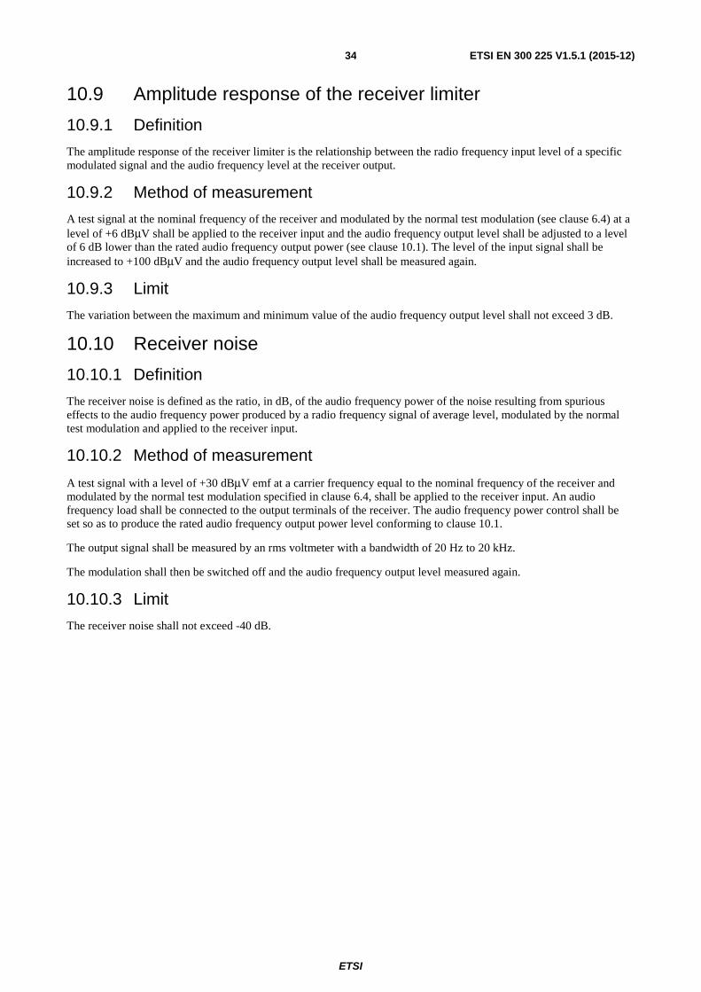
ETSI
ETSI EN 300 225 V1.5.1 (2015-12) 34
10.9 Amplitude response of the receiver limiter
10.9.1 Definition
The amplitude response of the receiver limiter is the relationship between the radio frequency input level of a specific modulated signal and the audio frequency level at the receiver output.
10.9.2 Method of measurement
A test signal at the nominal frequency of the receiver and modulated by the normal test modulation (see clause 6.4) at a level of +6 dBμV shall be applied to the receiver input and the audio frequency output level shall be adjusted to a level of 6 dB lower than the rated audio frequency output power (see clause 10.1). The level of the input signal shall be increased to +100 dBμV and the audio frequency output level shall be measured again.
10.9.3 Limit
The variation between the maximum and minimum value of the audio frequency output level shall not exceed 3 dB.
10.10 Receiver noise
10.10.1 Definition
The receiver noise is defined as the ratio, in dB, of the audio frequency power of the noise resulting from spurious effects to the audio frequency power produced by a radio frequency signal of average level, modulated by the normal test modulation and applied to the receiver input.
10.10.2 Method of measurement
A test signal with a level of +30 dBμV emf at a carrier frequency equal to the nominal frequency of the receiver and modulated by the normal test modulation specified in clause 6.4, shall be applied to the receiver input. An audio frequency load shall be connected to the output terminals of the receiver. The audio frequency power control shall be set so as to produce the rated audio frequency output power level conforming to clause 10.1.
The output signal shall be measured by an rms voltmeter with a bandwidth of 20 Hz to 20 kHz.
The modulation shall then be switched off and the audio frequency output level measured again.
10.10.3 Limit
The receiver noise shall not exceed -40 dB.

ETSI
ETSI EN 300 225 V1.5.1 (2015-12) 35
Annex A (normative): Measuring receiver for adjacent channel power measurement
A.1 Power measuring receiver specification
A.1.0 General The power measuring receiver is used for the measurement of the transmitter adjacent channel power. It consists of a mixer and oscillator, an IF filter, an amplifier, a variable attenuator and a level indicator as shown below (figure A.1).
Amplifier / Attenuator
Level Indicator
Mixer
Oscillator
Filter
Input
Figure A.1: Power measuring receiver
Instead of the Variable attenuator with the rms value indicator it is also possible to use a rms voltmeter calibrated in dB. The technical characteristics of the power measuring receiver are given in clauses A.1.1 to A.1.5.
A.1.1 IF filter The IF filter shall be within the limits of the following selectivity characteristics given in figure A.2.

ETSI
ETSI EN 300 225 V1.5.1 (2015-12) 36
Figure A.2
The selectivity characteristics shall keep the following frequency separations from the nominal centre frequency of the adjacent channel given in table A.1.
Table A.1: Selectivity characteristic
Frequency separation of filter curve from nominal centre frequency of adjacent channel (kHz) D1 D2 D3 D4 5 8,0 9,25 13,25
The attenuation points shall not exceed the following tolerances given in tables A.2 and A.3.
Table A.2: Attenuation points close to carrier
Tolerance range (kHz) D1 D2 D3 D4
+3,1 ±0,1 -1,35 -5,35
Table A.3: Attenuation points distant from the carrier
Tolerance range (kHz) D1 D2 D3 D4
±3,5 ±3,5 ±3,5 +3,5 -7,5
The minimum attenuation of the filter outside the 90 dB attenuation points shall be equal to or greater than 90 dB.
A.1.2 Attenuation indicator The attenuation indicator shall have a minimum range of 80 dB and a reading accuracy of 1 dB. With a view to future regulations an attenuation of 90 dB or more is recommended.
D4
D3
D2
D1D1
D2
D3
dB
90
26
6
2
0
D4
kHz
Distantfromcarrier
Closetocarrier

ETSI
ETSI EN 300 225 V1.5.1 (2015-12) 37
A.1.3 rms value indicator The instrument shall accurately indicate non-sinusoidal signals in a ratio of up to 10:1 between peak value and rms value.
A.1.4 Oscillator and amplifier The oscillator and the amplifier shall be designed in such a way that the measurement of the adjacent channel power of a low-noise un-modulated transmitter, whose self-noise has a negligible influence on the measurement result, yields a measured value of ≤ -90 dB.

ETSI
ETSI EN 300 225 V1.5.1 (2015-12) 38
Annex B (normative): Solar radiation test source
B.1 Simulated solar radiation source The intensity at the test point shall be 1 120 W/m2 ± 10 % with a spectral distribution given in table B.1.
The value 1 120 W/m2 shall include any radiation reflected from the text enclosure.
Table B.1: Spectral energy distribution and permitted tolerances
Spectral Region
Ultra-violet B Ultra-violet A Visible Infra-red
Bandwidth 0,28 µm -0,32 µm
0,32 µm -0,40 µm
0,40 µm -0,52 µm
0,52 µm -0,64 µm
0,64 µm -0,78 µm
0,78 µm -3,00 µm
Radiance 5 W/m2 63 W/m2 200 W/m2 186 W/m2 174 W/m2 492 W/m2 Tolerance ±35 % ±25 % ±10 % ±10 % ±10 % ±20 % NOTE: Radiation shorter than 0,30 μm reaching the earth's surface is insignificant.

ETSI
ETSI EN 300 225 V1.5.1 (2015-12) 39
History
Document history
Edition 1 May 1994 Publication as ETSI I-ETS 300 225
Edition 2 April 1997 Publication as ETSI ETS 300 225
Edition 3 January 1998 Publication as ETSI ETS 300 225
V1.4.1 December 2004 Publication
V2.1.0 September 2015 EN Approval Procedure AP 20151206: 2015-09-07 to 2015-12-07
V1.5.1 December 2015 Publication


![IIIIIIIIIIIIIIIIIIIIIIIIIUS 2018 / 0157243 A1 Jun . 7 , 2018 ( 0028 ] Optionally , the field function is equation ( 3 ) , defined below . 100291 Optionally , the method further includes](https://img.pdfslide.us/doc/110x75/5ea2774c3798d25b41046eed/iiiiiiiiiiiiiiiiiiiiiiiii-us-2018-0157243-a1-jun-7-2018-0028-optionally.jpg)