Embed Size (px)
DESCRIPTION
electrical
Citation preview
BRITISH STANDARD
BS EN 13463-5:2003Non-electrical equipment intended for use in potentially explosive atmospheres —
Part 5: Protection by constructional safety “c”
The European Standard EN 13463-5:2003 has the status of a British Standard
ICS 13.230
���������������� ������������������������������� �������������
BS EN 13463-5:2003
This British Standard, was published under the authority of the Standards Policy and Strategy Committee on 12 December 2003
© BSI 12 December 2003
ISBN 0 580 43093 6
National foreword
This British Standard is the official English language version of EN 13463-5:2003.
The UK participation in its preparation was entrusted to Technical Committee FSH/23, Fire precautions in industrial and chemical plant, which has the responsibility to:
A list of organizations represented on this committee can be obtained on request to its secretary.
Cross-referencesThe British Standards which implement international or European publications referred to in this document may be found in the BSI Catalogue under the section entitled “International Standards Correspondence Index”, or by using the “Search” facility of the BSI Electronic Catalogue or of British Standards Online.
This publication does not purport to include all the necessary provisions of a contract. Users are responsible for its correct application.
Compliance with a British Standard does not of itself confer immunity from legal obligations.
— aid enquirers to understand the text;
— present to the responsible international/European committee any enquiries on the interpretation, or proposals for change, and keep the UK interests informed;
— monitor related international and European developments and promulgate them in the UK.
Summary of pages
This document comprises a front cover, an inside front cover, the EN title page, pages 2 to 29 and a back cover.
The BSI copyright notice displayed in this document indicates when the document was last issued.
Amendments issued since publication
Amd. No. Date Comments
EUROPEAN STANDARD
NORME EUROPÉENNE
EUROPÄISCHE NORM
EN 13463-5
December 2003
ICS 13.230
English version
Non-electrical equipment intended for use in potentiallyexplosive atmospheres - Part 5: Protection by constructional
safety “c”
Appareils non électriques destinés à être utilisés enatmosphères explosibles - Partie 5: Protection par sécurité
de construction “c”
Nicht-elektrische Geräte für den Einsatz inexplosionsgefährdeten Bereichen - Teil 5: Schutz durch
Konstruktive Sicherheit “c”
This European Standard was approved by CEN on 1 September 2003.
CEN members are bound to comply with the CEN/CENELEC Internal Regulations which stipulate the conditions for giving this EuropeanStandard the status of a national standard without any alteration. Up-to-date lists and bibliographical references concerning such nationalstandards may be obtained on application to the Management Centre or to any CEN member.
This European Standard exists in three official versions (English, French, German). A version in any other language made by translationunder the responsibility of a CEN member into its own language and notified to the Management Centre has the same status as the officialversions.
CEN members are the national standards bodies of Austria, Belgium, Czech Republic, Denmark, Finland, France, Germany, Greece,Hungary, Iceland, Ireland, Italy, Luxembourg, Malta, Netherlands, Norway, Portugal, Slovakia, Spain, Sweden, Switzerland and UnitedKingdom.
EUROPEAN COMMITTEE FOR STANDARDIZATIONC OM ITÉ EUR OP ÉEN DE NOR M ALIS AT IONEUROPÄISCHES KOMITEE FÜR NORMUNG
Management Centre: rue de Stassart, 36 B-1050 Brussels
© 2003 CEN All rights of exploitation in any form and by any means reservedworldwide for CEN national Members.
Ref. No. EN 13463-5:2003 E
EN 13463-5:2003 (E)
2
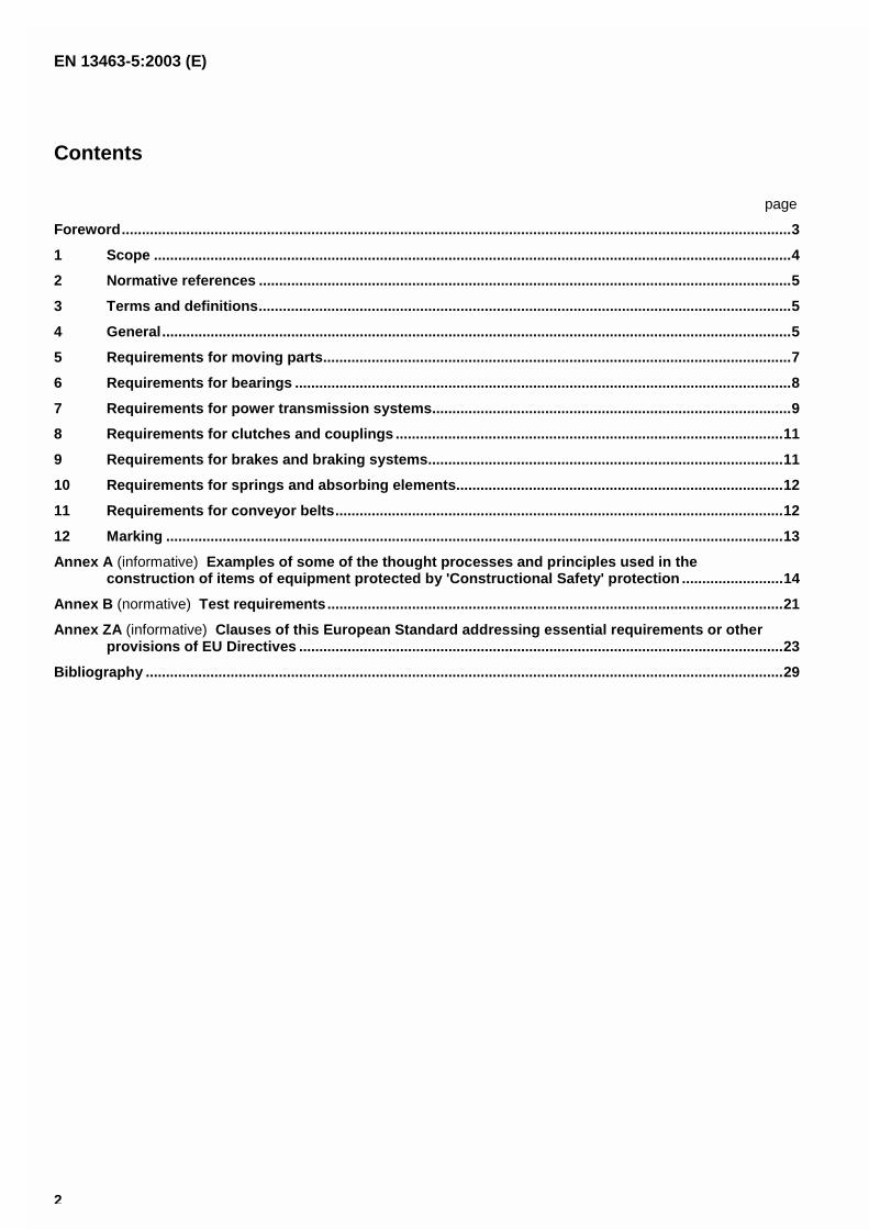
Contents
page
Foreword....................................................................................................................... ...............................................3
1 Scope ......................................................................................................................... .....................................4
2 Normative references .......................................................................................................... ..........................5
3 Terms and definitions......................................................................................................... ...........................5
4 General....................................................................................................................... .....................................5
5 Requirements for moving parts................................................................................................. ...................7
6 Requirements for bearings ..................................................................................................... ......................8
7 Requirements for power transmission systems................................................................................... ......9
8 Requirements for clutches and couplings ....................................................................................... .........11
9 Requirements for brakes and braking systems................................................................................... .....11
10 Requirements for springs and absorbing elements.............................................................................. ...12
11 Requirements for conveyor belts.............................................................................................. .................12
12 Marking ...................................................................................................................... ...................................13
Annex A (informative) Examples of some of the thought processes and principles used in theconstruction of items of equipment protected by 'Constructional Safety' protection .........................14
Annex B (normative) Test requirements............................................................................................................ .....21
Annex ZA (informative) Clauses of this European Standard addressing essential requirements or otherprovisions of EU Directives .................................................................................................... ....................23
Bibliography ................................................................................................................... ...........................................29

EN 13463-5:2003 (E)
3
Foreword
This document EN 13463-5:2003 has been prepared by Technical Committee CEN/TC 305 “Potentially explosiveatmospheres - Explosion prevention and protection”, the secretariat of which is held by DIN.
This European Standard shall be given the status of a national standard, either by publication of an identical text orby endorsement, at the latest by June 2004, and conflicting national standards shall be withdrawn at the latest byJune 2004.
This document has been prepared under a mandate given to CEN by the European Commission and the EuropeanFree Trade Association, and supports essential requirements of EU Directive(s).
For relationship with EU Directive(s), see informative Annex ZA, which is an integral part of this document.
Annex A is informative. Annex B is normative.
This document includes a Bibliography.
According to the CEN/CENELEC Internal Regulations, the national standards organizations of the followingcountries are bound to implement this European Standard: Austria, Belgium, Czech Republic, Denmark, Finland,France, Germany, Greece, Hungary, Iceland, Ireland, Italy, Luxembourg, Malta, Netherlands, Norway, Portugal,Slovakia, Spain, Sweden, Switzerland and the United Kingdom.
EN 13463-5:2003 (E)
4
Introduction
Non-electrical equipment has been used for over 150 years in industries having potentially explosive atmospheresand a great deal of experience has been gained in the application of protective measures to reduce the risk of ignitionto an acceptably safe level. With the introduction of the ATEX Directive 94/9/EC and the inclusion of non-electricalequipment in its scope, it became necessary to produce ignition protection concept standards which clearly definedthese protective measures and incorporated the extensive and diverse experience gained over the years.
One of the methods of applying ignition protection, had been to select types of equipment not containing an ignitionsource in normal service and then apply good engineering principles, so that risk of mechanical failures likely to createincendive temperatures or sparks, was reduced to a very low level. Such protective measures are referred to in thisstandard as ignition protection by 'Constructional Safety', or type of protection 'c'.
The purpose of this standard, is therefore to specify the requirements for equipment, protected by the type ofprotection 'c' which meets the essential safety and health requirements described in Directive 94/9/EC.
1 Scope
1.1 This European standard specifies the requirements for the design and construction of non-electrical equipment,intended for use in potentially explosive atmospheres, protected by the type of protection Constructional Safety "c".
1.2 This standard supplements the requirements in EN 13463-1, the contents of which also apply in full toequipment constructed in accordance with this standard.
1.3 Equipment complying with the relevant clauses of this standard meet the requirements for the followingcategories:
Equipment Group I Category M2;
Equipment Group II Category 2G or 2D;
Equipment Group II Category 1G or 1D;
NOTE The requirements for Group I, Category M1 equipment, are given in EN 50303 which specifies the requirements forboth electrical and non-electrical equipment.
1.4 The type of ignition protection described in the standard can be used either on it's own or in combination withother types of ignition protection to meet the requirements for equipment of Group I, categories M1 and M2 orGroup II, categories 1 and 2 depending on the ignition hazard assessment in EN 13463-1.
EN 13463-5:2003 (E)
5
2 Normative references
This European Standard incorporates by dated or undated reference, provisions from other publications. Thesenormative references are cited at the appropriate places in the text and the publications are listed hereafter. Fordated references, subsequent amendments to or revisions of any of these publications apply to this EuropeanStandard only when incorporated in it by amendment or revision. For undated references the latest edition of thepublication referred to applies (including amendments).
EN 982, Safety of machinery - Safety requirements for fluid power systems and their components – Hydraulics.
EN 983, Safety of machinery - Safety requirements for fluid power systems and their components – Pneumatics.
EN 1127-1:1997, Explosive atmospheres - Explosion prevention and protection - Part 1: Basic concepts andmethodology.
EN 1127-2:2002, Explosive atmospheres - Explosion prevention and protection – Part 2: Basic concepts andmethodology for mining.
EN 13463-1:2001, Non-electrical equipment for potentially explosive atmospheres - Part 1: Basic method andrequirements.
prEN 13463-6, Non-electrical equipment for potentially explosive atmospheres — Part 6: Protection by control ofignition source 'b'.
EN 13463-8, Non-electrical equipment for potentially explosive atmospheres — Part 8: Protection by liquidimmersion 'k'.
EN 13478, Safety of machinery - Fire prevention and protection
EN 13501-1, Fire classification of construction products and building elements - Part 1: Classification using testdata from reaction to fire tests
EN 60529:1991, Degrees of protection provided by enclosures (IP Code), (IEC 60529:1989).
3 Terms and definitions
For the purposes of this European Standard, the terms and definitions given in EN 13463-1:2001, EN 1127-1:1997and EN 1127-2:2002 and the following apply.
3.1type of protection constructional safety "c"type of ignition protection in which constructional measures are applied so as to protect against the possibility ofignition from hot surfaces, sparks and adiabatic compression generated by moving parts
3.2mechanical sparkssparks, as well as showers of sparks, produced by impact or friction between two similar or dissimilar solid materials
4 General
4.1 Determination of suitability
Before a decision is made to protect equipment or pieces of equipment for use as an assembly includinginterconnecting parts by the measures described in this standard, it shall have been subjected to the ignition hazardassessment in accordance with EN 13463-1. Furthermore, It shall also have been determined that, by enhancing orincreasing the safety of certain vulnerable parts, the required level of protection is ensured against the possibility ofignition sources occurring.
EN 13463-5:2003 (E)
6
4.2 Parts of equipment
All parts and interconnecting parts of equipment shall be capable of functioning in conformity with the operationalparameters established by the manufacturer throughout their foreseeable lifetime and be sufficiently firm and durableto withstand the mechanical and thermal stresses to which they will be subjected.
4.3 Ingress Protection
4.3.1 General
The degree of ingress protection (IP) provided by the outer enclosures of equipment depends upon its intendedduty and the type of environment it is designed to be used in. An appropriate rating, according to IP category 1, asspecified in 13.4 of EN 60529:1991, shall be determined as part of the ignition hazard assessment (see 4.1) andshall be able to prevent foreign objects or water entering the equipment which could:
i) reduce the ignition level to a lower value, by for example, allowing combustible dust, with a lowerignition temperature than the potentially explosive atmosphere, to form a layer on hot internalcomponents or parts of the equipment; and/or
ii) make contact with moving parts, resulting in the creation of a potential ignition source, unsafemalfunction or fire.
The following subclauses, 4.3.3 to 4.3.5 below, specify the minimum degree of ingress protection (IP) for enclosuresused in the circumstances described.
4.3.2 In the case of equipment intended for use in gas/vapour atmospheres, where entry of foreign objects cancause ignition, but entry of dust is harmless, entry of falling objects shall be prevented.
4.3.3 In the case of equipment intended for use in gas/vapour atmospheres, where the entry of dusts or liquidscould cause malfunction leading to an ignition source, the enclosure shall be at least IP 54.
4.3.4 In the case of equipment intended for use in potentially explosive dust atmospheres, where ingress of dustcan result in an ignition source or fire, the enclosure shall be at least IP 6X.
4.3.5 In the case of equipment intended for use in potentially explosive dust atmospheres, where ingress of dustand foreign objects are not likely to cause an ignition, no enclosure is necessary.
NOTE An enclosure can be required for other safety reasons, e.g. IP 2X to prevent parts of the body coming into contactwith rotating parts.
4.4 Seals for moving parts
4.4.1 Unlubricated gaskets, seals, sleeves, bellows and diaphragms
Unlubricated gaskets, seals, sleeves, bellows and diaphragms which are subject to rubbing contact in normaloperation or during foreseeable malfunction, shall not contain light metals. Sleeves made of elastomeric material,PTFE or similar material, graphite and ceramics are suitable.
Non-metallic materials shall be resistant to distortion and degradation without reducing the effectiveness of explosionprotection (see EN 13463-1).
4.4.2 Stuffing box seals
Stuffing-box seals shall only be used if a temperature rise above the maximum surface temperature can be excluded.
NOTE A device to monitor temperatures and switch off equipment should be employed.
4.4.3 Lubricated seals
Seals which normally require the presence of a replenishable lubricant to prevent hot surfaces occurring at theirinterface with equipment parts shall be designed to ensure the sufficient presence of lubricant or shall be protectedby one of the following means:
EN 13463-5:2003 (E)
7
- provision of an effective means to monitor the continued presence of the lubricant; or
- provision of a temperature detection device to warn of increasing temperatures; or
- design of the equipment to be capable of completing the ‘dry run’ test, as described in annex B, without exceedingthe maximum surface temperature of the equipment and/or suffering damage which would reduce the effectivenessof its ignition protection properties.
NOTE Monitoring can be either continuous or by appropriate inspection and examination.
The manufacturer's instructions shall include details relating to the correct lubrication, monitoring and maintenance ofsuch seals.
4.5 Equipment lubricants/ Coolants/ Fluids
4.5.1 Lubricants and/or coolants, which are required for the prevention of potentially incendive hot surfaces ormechanical sparks (see EN 13463-8), shall have an ignition temperature (see IEC 60079-4) at least 50 K above themaximum surface temperature of the equipment where the liquid is being used.
4.5.2 Any fluid which can be released shall not cause an ignition.
NOTE For example due to high temperature or electrostatic charging.
5 Requirements for moving parts
5.1 General
The ignition hazard assessment (see 4.1) shall identify those moving parts which through premature failure, orwear, could lead to the occurrence of unsafe vibration or impact or friction. Such parts shall either be constructed insuch a way so that either they do not become an ignition source during the lifetime of the equipment, taking theequipment category into consideration or manufacturers instructions shall specify the measures to be taken.
NOTE Slow moving parts with a circumferential speed of less than 1 m/s do not normally need protection against heating byfriction and mechanical sparks. For equipment with very high speed moving parts Constructional Safety "c" might not be suitable. Inthese cases other types of protection should be considered, for example, a flameproof 'd' enclosure or a pressurised 'p' enclosure.
5.2 Vibration
Unintentional vibration from moving parts leading to the creation of potentially incendive hot surfaces or mechanicalsparks, shall be avoided. Unintentional vibration can arise from equipment itself, or from the place where it ismounted. Potential incendive hot surfaces or mechanical sparks from this cause shall be avoided. Themanufacturer shall provide any necessary installation, operation and maintenance instructions. In particular theinstructions shall specify the correct operating speed range of the equipment.
NOTE 1 Alternatively the equipment can be provided with a vibration controlling device arranged to control any potentialsource of ignition associated with excessive vibration of moving parts (see prEN 13463-6).
NOTE 2 Where the melting point of the material used in the construction of moving parts is below the maximum surfacetemperature of the equipment, or is not capable of causing potentially incendive hot surfaces and/or mechanical sparks, additionalprotective measures are not normally necessary (e.g. the provision of a low melting point sacrificial wear plate; the use of a plasticfan inside a metal housing, or a metallic fan with sacrificial non-sparking low melting point fan blade-tips).
5.3 Clearance
Clearances between non-lubricated moving parts and fixed parts shall be dimensioned so that frictional contact, ableto produce potentially incendive hot surfaces and/or mechanical sparks, are avoided (see the above note for some ofthe precautions which may be adopted for the purpose of foreseeable malfunction).
NOTE In the case of parts protected by fluids see EN 13463-8.

EN 13463-5:2003 (E)
8
5.4 Lubrication
Moving parts which depend on the presence of a lubricating medium to prevent a temperature rise exceeding themaximum surface temperature, or the creation of incendive mechanical sparks shall be constructed to ensure thepresence of the lubricating medium. This can be achieved by an oil splash lubricator, or an automatic greasingsystem or a manual system of monitoring the oil level, together with suitable instructions about regular servicingand the recommended frequency of inspection. Where this is not possible alternative measures to control theignition risk shall be used. (e.g. temperature sensors which operate an alarm before a potentially incendivetemperature is reached, or a temperature sensor arranged to control the potential source of ignition (see prEN13463-6).
Where equipment is designed to process liquids as part of its duties and the presence of the process liquid isessential for the purpose of lubrication, cooling, quenching, or ignition prevention, this shall be stated in themanufacturer's instructions, as required by EN 13463-1.
6 Requirements for bearings
6.1 General
Bearings are basically divided into three types, sliding plane motion, sliding rotary motion and rolling element.When assessing bearings, as part of the ignition hazard assessment required by EN 13463-1 (see 4.1), thefollowing (which is not a definitive list) shall be taken into account:
• the bearing shall be designed for the equipment’s intended duty e.g. speed, loading and variations of speedand loading;
• the bearing’s basic rated life. As described in ISO 281 for rolling element bearings. (see also NOTE 1 below);
• the proper fit of the bearings in their housing and on the shaft (tolerances, roundness and surface quality),taking into consideration the vertical and axial loads on the bearing with respect to shaft and housing;
• the correct alignment of the bearings;
• the axial and radial loading of the bearings caused by thermal expansion of the shaft and the housing under themost severe operating conditions;
• protection of the bearing from ingress of water and solids, if necessary to avoid premature failure;
• protection of the bearing from electrical currents, including stray circulating currents (which can cause, forexample, incendive sparking, or spark erosion leading to premature failure, at the point of contact between theball and ball race of a ball bearing);
• the provision of adequate lubrication, according to the lubricating regime necessary for the type of bearing (e.g.for sliding bearings, boundary lubrication, mixed film, or full film hydrodynamic lubrication are the mostcommonly used regimes);
• recommended maintenance intervals;
• replacement after unacceptable wear or the end of its recommended life, whichever comes first;
• protection of the bearing from vibration, especially at standstill.
Where any of the above relies on the user performing manual checks to detect malfunction or impendingmalfunction, the necessary information shall be included in the manufacturer’s instructions required by EN 13463-1.
For category 1 equipment the manufacturer shall specify any necessary running in period, during which time nosource of a flammable atmosphere should exist around the equipment.
NOTE 1 At the present time, no suitable experimental test exists to demonstrate that a given type of bearing has a low risk ofbecoming an ignition source in service. Ball and roller bearing manufacturers do however quote a basic rated life corresponding
EN 13463-5:2003 (E)
9
to a probability of mechanical failure occurring during operation (e.g. failure by deformation of an element, or fatigue flaking orspalling occurring on one of its elements). This basic rating can be used in the ignition hazard assessment in an attempt todetermine the risk of bearing malfunction that might lead to the production of an incendive hot surface or sparks. The basic ratedlife of a ball/roller bearing is based on the amount of radial and axial loading that a ball/roller bearing can theoretically endure forone million revolutions. It is usually expressed as an “L” value in terms of foreseeable lifetime operating revolutions, orforeseeable lifetime hours of service. In an attempt to reduce the risk of malfunction in service to a minimum, it is paramount thatthe equipment manufacturer pays attention to good design, the ratio of the axial and radial loadings, construction, lubrication,cooling, and maintenance procedures. Also that regular examination is recommended during operation, in an attempt to detectimpending malfunction.
NOTE 2 The service life of bearings depends greatly on the service conditions and it is therefore not possible to calculatetheir service life reliably.
NOTE 3 Plain bearings are not affected, because it is not possible to calculate their service life. Lubrication should beensured as specified in 6.2.
Bearings shall conform to the current state of technology. They shall be regularly inspected and/or monitored inorder to prevent risk of ignition.
The manufacturer's instructions for the equipment shall include details of necessary servicing, service frequencyand appropriate maintenance.
6.2 Lubrication
Bearings which depend on the presence of a lubricating medium to prevent a temperature rise exceeding themaximum surface temperature, or the creation of incendive mechanical sparks shall be constructed to ensure thepresence of the lubricating medium. This can be achieved by bearings that are sealed for life, an oil splashlubricator, or an automatic greasing system or a manual system of monitoring the oil level, together with suitableinstructions about regular servicing and the recommended frequency of inspection. Where this is not possiblealternative measures to control the ignition risk shall be used (e.g. temperature sensors which operate an alarmbefore a potentially incendive temperature is reached, or a temperature sensor arranged to control the potentialsource of ignition (see prEN 13463-6).
Where equipment is designed to process liquids as part of its duties and the presence of the process liquid isessential for the purpose of lubrication, cooling, quenching, or ignition prevention, this shall be stated in themanufacturer's instructions, as required by EN 13463-1.
6.3 Chemical compatibility
Bearings shall be made of materials resistant to the liquids, or vapours, in which they are intended to be used.Similarly, the material used in the construction of the bearing, including any bearing cages, shall be resistant to anyliquids or solvents which can come into contact with them. Particular attention shall be given to the possibility ofswelling of non-metallic parts. Where liquids or vapours can dissolve in the lubricant of the bearings, the lubricant shallremain 'fit for purpose' even in this condition.
7 Requirements for power transmission systems
7.1 Gear drives
7.1.1 Gear drives shall comply with the requirements of clause 5. Where the ignition hazard assessment (4.1)shows there could still be an ignition source another form of ignition protection shall be used (e.g. EN 13463-8protection by liquid immersion).
7.1.2 Where equipment includes facilities to change the gear ratios (manually, or automatically), the gear changingmechanisms shall be so arranged as to ensure that they are incapable of producing either temperatures exceedingthe maximum surface temperature or incendive mechanical sparks.
7.2 Belt drives
7.2.1 Power transmission belts shall be incapable of developing an incendive electrostatic discharge duringoperation (see ISO 1813 and CENELEC Technical Report – CLC/TR 50404: 2003-6).
EN 13463-5:2003 (E)
10
7.2.2 The materials used in the construction shall be non-combustible and/or not supporting or propagatingcombustion. These are e.g. materials classified as A1, A2 or B according to EN 13501-1 (see EN 13478). Theirselection shall be made under consideration of the risk analysis.
7.2.3 For drives which could cause surfaces to exceed the maximum surface temperature if the belt becomesslack or slips on the pulley, the correct belt tension shall be maintained.
NOTE Devices used to ensure correct belt tension can also serve to detect broken belts.
7.2.4 With drives which could cause surfaces to exceed the maximum temperature if they run out of alignment,true alignment shall be maintained (see 7.2.3).
NOTE Alternatively, belt drives can be fitted with devices to monitor temperature, in order to prevent surfaces becoming anignition risk (see prEN 13463-6).
7.2.5 The supporting frame, chassis, or structure, of equipment containing belt(s) shall be constructed ofelectrically conducting material and shall be so arranged as to provide a leakage path to earth for any staticelectricity which occurs on the belt(s). The frame, chassis or structure includes the driving pulley or drum and anyidler pulleys or rollers associated with the belt drive. Specific electrical bonding between the separate parts andearth shall be provided where the electrical resistance of the leakage path to earth exceeds 1 Giga-Ohm.
NOTE Where the drive pulley or drive roller is powered by a mains fed electrical motor the electrical connection to earth,normally provided for the electric motor, can be taken into account.
7.2.6 Drives capable of producing hot surfaces exceeding the maximum surface temperature, as a result of thestalling of the output power shaft, while the input continues to rotate, shall have means to detect the stalled output,and prevent ignition.
7.3 Chain drives
Chain drives shall comply with the requirements of clause 5.
Chain drives operating at speeds greater than 1 m/s,and containing a potential ignition source (identified by theignition hazard assessment required by EN 13463-1), shall be fitted with means to ensure continuous positiveengagement of the chain with its associated sprocket. Where this is not possible, it shall be fitted with a device thatremoves the driving power to the drive sprocket in the event of the chain breaking, becoming disengaged, orslackening beyond a limit specified by the manufacturer’s instructions (see prEN 13463-6).
7.4 Other Drives
Other drives shall fulfil the requirements set out in clause 5.
7.5 Hydrostatic/Hydrokinetic/Pneumatic – equipment
7.5.1 Hydrostatic/hydrokinetic and pneumatic power transmission equipment shall be constructed of pipes,enclosures and/or other external parts, which do not produce hot surfaces exceeding the maximum surfacetemperature, even when operating continuously at maximum normal rating.
7.5.2 Hydrostatic/hydrokinetic equipment shall comply with the requirements of EN 982.
7.5.3 Pneumatic equipment shall comply with the requirements of EN 983.
7.5.4 The maximum temperature of any power transmission fluid which can be released shall not exceed themaximum surface temperature of the equipment, if this can create an ignition risk.
NOTE A suitable over-temperature protection device, can be a fusible plug in a fluid coupling which melts to release thepower transmission fluid from the coupling during overload/over-temperature (see prEN 13463-6).
7.5.5 To prevent ignition of the explosive atmosphere by burning liquid the power transmission fluid shall have asuitable fire resistance rating.
NOTE 1 For Group I equipment this can be achieved by using a liquid with a fire resistance rating of at least "2", when testedin accordance with the 'Community of Six Spray ignition Test' and a persistence of flame not exceeding 30 s, when tested inaccordance with the 'Wick test', as described in 3.1.1 and 3.2 of the European Safety and Health Commission for Mining and
EN 13463-5:2003 (E)
11
Other Extractive Industries (SHCMOEI) document - "Specifications and Testing Conditions Relating to Fire Resistant FluidsUsed for Power Transmission (Hydrostatic and Hydrokinetic)"
NOTE 2 National legislation in member states can require the use of different fire resistant fluids in certain hydraulic systems.
7.5.6 Air compressors used for pneumatic equipment shall:
incorporate a filter on the intake system to prevent the ingress of dust or similar foreign material into the partswhere compression takes place;
contain only lubricants which are resistant to carbonisation;
NOTE 1 Carbonisation of compressor lubricant (caused by exposure to elevated temperatures) results in the formation of oilycarbon deposits in the compressor delivery which can cause it to overheat and explode.
NOTE 2 For fluids operating at high pressure (e.g. inside compressors) allowance should be made for the fact that theignition temperature is lowered by increased operating pressure.
8 Requirements for clutches and couplings
8.1 Clutches and couplings, shall be arranged or monitored (see prEN 13463-6) so that no fixed or moving partthat is exposed to the potentially explosive atmosphere exceeds the maximum surface temperature of theequipment. In the case of plastic or other non-metallic parts of a clutch or coupling, their material or arrangementshall exclude the possibility of an incendive electrostatic discharge.
NOTE Examples of the above types of clutch and coupling are friction plate clutches, bell type centrifugal clutches, fluidcouplings and scoop-controlled fluid couplings.
8.2 During the period of full engagement, there shall be no slipping, or similar relative movement between the inputand output mechanisms likely to cause a hot surface exceeding the maximum surface temperature.
NOTE The above requirements can be achieved by one or more of the following preventative methods (see prEN13463-6):
fitting an overload/ over-temperature protection device, for example a fusible plug in a fluid coupling which 'ruptures' torelease the power transmission fluid from the coupling during overload/over-temperature; or
fitting a control device(s), so arranged as to remove the input drive power, if any part of the coupling or clutchassembly, or its housing, attains the maximum surface temperature, or
a control device, or devices, so arranged as to remove the drive power, if slippage occurs, because of malfunction,incorrect adjustment, or excessive wear on the mechanisms / friction pads (e.g. clutch plates).
8.3 So as to prevent unsafe frictional heating, the maximum time taken for mechanisms to achieve full-engagementfrom a standing start, or full disengagement, shall not cause the equipment to exceed the maximum surfacetemperature. One method of achieving this is to determine the maximum safe engaging time as described in B.2.
9 Requirements for brakes and braking systems
9.1 Brakes used only for stopping in emergency
Brakes, designed to be used only for emergency stopping of equipment, shall be constructed so that allowing for themaximum kinetic energy to be dissipated, neither shall the maximum surface temperature be exceeded nor shallincendive sparks be generated at any part exposed to the potentially explosive atmosphere.
NOTE For a low likelihood of response of an emergency stopping device the hazard assessment according to 4.1 cancome to the result that no further means of protection relating to equipment in this category are necessary.
EN 13463-5:2003 (E)
12
9.2 Service brakes (including friction brakes and fluid based retarders)
Service brakes shall be constructed to allow for the maximum kinetic energy to be dissipated so that neither shallthe maximum surface temperature be exceeded nor shall incendive sparks be generated at any part exposed to thepotentially explosive atmosphere.
NOTE It will frequently be strongly recommended to take other protective measures to prevent sources of ignition fromdeveloping.
9.3 Parking brakes
Parking brakes shall be fitted with an interlock which prevents the drive power being applied if the brake is not fullyreleased. Alternatively a control device shall be fitted.
10 Requirements for springs and absorbing elements
Springs and absorbing elements shall be constructed and, where necessary, provided with lubrication and/or cooling,so that no part exposed to the potentially explosive atmosphere either produces a hot surface exceeding themaximum surface temperature or incendive mechanical sparks if they fracture or break in service.
11 Requirements for conveyor belts
NOTE The ignition protection of Category M2 mining conveyor belts is also dealt with in prEN 1710.
11.1 Conveyor belts shall be incapable of developing an incendive electrostatic discharge during operation (seeCENELEC Technical Report – CLC/TR 50404:2003-6)
11.2 The materials used in the construction shall be non-combustible and/or not supporting or propagatingcombustion. These are e.g. materials classified as A1, A2 or B according to EN 13501-1 (see EN 13478). Theirselection shall be made under consideration of the risk analysis.
NOTE 1 The requirements for conveyor belts used in underground mining comply with these requirements and are laid downin EN 1710.
NOTE 2 Member state mining legislation can require mining conveyor belts to pass more stringent fire resistance tests, basedon the application of a propane gas burner to a test sample; a full scale fire test in a mining gallery, and a rotating conveyordrive roller in contact with a stationery conveyor belt."
11.3 Drives capable of producing hot surfaces exceeding the maximum surface temperature, as a result ofslackening or slipping of the belt on the conveyor drive, or other rollers, shall be fitted with a means to ensure thatthe correct belt tension, as recommended by the manufacturer, is maintained.
NOTE This can be achieved by either monitoring the tension in the belt, or by comparing the relative speeds of the driveroller and the belt.
If the relative speeds of the drive roller and the belt are being compared, a difference exceeding 10% should cause the drivepower to be removed.
11.4 Drives capable of producing hot surfaces exceeding the maximum surface temperature, by running out ofalignment, shall be fitted with a means to detect incorrect alignment.
NOTE As an alternative to the protective means referred to in 11.3 and 11.4, the belt drive assembly can be fitted withtemperature controlling devices, arranged to ensure that any potentially incendive hot surfaces are prevented from occurring(see prEN 13463-6).
11.5 The supporting frame, chassis, or structure of equipment containing belt(s) shall be constructed of electricallyconducting material and shall be so arranged as to provide a leakage path to earth for any static electricity whichoccurs on the belt(s). The frame, chassis or structure includes the driving pulley or drum and any idler pulleys orrollers associated with the belt drive. Specific electrical bonding between the separate parts and earth shall beprovided where the electrical resistance of the leakage path to earth exceeds 1 Giga-Ohm.
EN 13463-5:2003 (E)
13
NOTE Where the drive pulley or drive roller is powered by a mains fed electrical motor the electrical connection to earth,normally provided for the electrical motor, can be taken into account.
12 Marking
12.1 In addition to the marking requirements of EN 13463-1, the specific marking necessary for compliance withthis standard shall include :
- the symbol 'c' (designating the type of explosion protection);
12.2 Example of the marking in relation to the explosion protection for Group II, Category 2 equipment, intended foruse in a potentially explosive atmosphere of gas :
12.3 Example of the marking in relation to the explosion protection for Group I, Category M 2 equipment :
������������
�������
EN 13463-5:2003 (E)
14
Annex A(informative)
Examples of some of the thought processes and principles used in theconstruction of items of equipment protected by 'Constructional Safety'
protection
A.1 Ignition hazard assessment relating to a Group II, category 2 pump, normally used inchemical industry
A.1.1 Description of use
The equipment is a centrifugal pump designed for use in places where a source of release of flammable materialsgives rise to a zone 1 potentially explosive atmosphere. The pump is driven by a flameproof electric motor that hasbeen certified by a notified body as category 2 electrical equipment and is suitable for the potentially explosiveatmosphere surrounding it. The pump has a single roller bearing at the drive end of the impeller shaft. It is designedfor pumping liquid solvents which may produce a flammable vapour.
A.1.2 Construction
The pump has an outer casing/body of stainless steel which is corrosion resistant to the material being pumped. Iteasily passes the mechanical tests (impact test) described in EN 13463-1. There are no exposed light metal orplastic parts that need consideration, or other relevant restrictions described in EN 13463-1.
The pump’s design and strength is of high integrity, such that it will not leak even in the event of a foreseeablemalfunction. It normally runs full of liquid, but is not self priming and the possibility of it running dry should beconsidered. It has a double mechanical seal, with lubricant pumped between the seals.
The pump mountings have been designed to withstand the expected vibration from the pump during operation andto avoid early failure of the pump casing by vibration fatigue, or misalignment with the drive at 10% over- speed.
A.1.3 Ignition hazard assessment
The ignition hazard assessment according to 5.2 of EN 13463-1:2001 identifies that, because of its construction,and temperature classification testing, no ignition sources exist in normal operation.
As the pump is to be designated as Group II, category 2 equipment, the hazard assessment has, by definition ofthat category, to take account of “foreseeable malfunction”. Further assessment therefore shows the followingforeseeable malfunctions are possible ignition sources:
running with no liquid in the pump;
misalignment of the pump and drive;
failure of the seal on the rotating shaft;
pumping against a closed outlet;
pump run at over-speed;
solid material in the liquid fed to the pump;
swelling of some seals in the presence of particular solvents;
failure of the drive shaft bearing;
break up of the impeller rotor.
EN 13463-5:2003 (E)
15
The pump can be described as protected by constructional safety if all these equipment operating faults can becontrolled using the methods described in this standard.
A.1.4 Determining the ignition protection
For protection against ignition during foreseeable malfunction, some consideration has been given to making theouter shell of the pump into a flameproof ‘d’ enclosure. This has the advantage of enclosing all of the potentialignition sources in a protective enclosure. It does however result in the pump becoming unnecessarily large andexpensive to manufacture. This possibility has therefore been rejected in favour of constructional safety asdescribed below in the ignition hazard document.
A.1.5 The ignition hazard assessment document
A copy of the ignition hazard document is attached. This document is placed in the manufacturer’s technical filewhich has to be deposited with the selected notified body if compliance with 94/9/EC is being claimed and thepump is to bear the “CE” marking.
A.1.6 Marking with regard to the ignition protection
EN 13463-1 requires the equipment to be marked with the symbol(s) of the ignition protection used. In thisparticular case, the pump complies with EN 13463-1 and this standard. The symbol ‘c’ will therefore be included inthe marking.
EN 13463-5:2003 (E)
16
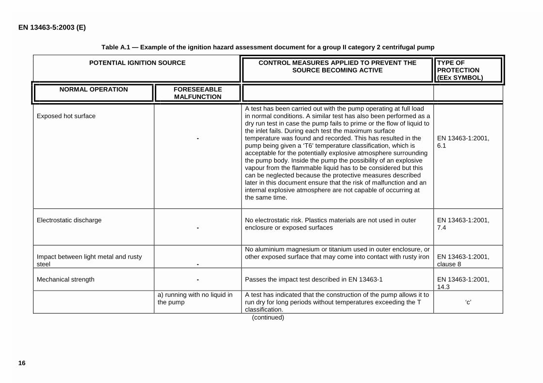
Table A.1 — Example of the ignition hazard assessment document for a group II category 2 centrifugal pump
POTENTIAL IGNITION SOURCE CONTROL MEASURES APPLIED TO PREVENT THESOURCE BECOMING ACTIVE
TYPE OFPROTECTION(EEx SYMBOL)
NORMAL OPERATION FORESEEABLEMALFUNCTION
Exposed hot surface
-
A test has been carried out with the pump operating at full loadin normal conditions. A similar test has also been performed as adry run test in case the pump fails to prime or the flow of liquid tothe inlet fails. During each test the maximum surfacetemperature was found and recorded. This has resulted in thepump being given a ‘T6’ temperature classification, which isacceptable for the potentially explosive atmosphere surroundingthe pump body. Inside the pump the possibility of an explosivevapour from the flammable liquid has to be considered but thiscan be neglected because the protective measures describedlater in this document ensure that the risk of malfunction and aninternal explosive atmosphere are not capable of occurring atthe same time.
EN 13463-1:2001,6.1
Electrostatic discharge-
No electrostatic risk. Plastics materials are not used in outerenclosure or exposed surfaces
EN 13463-1:2001,7.4
Impact between light metal and rustysteel -
No aluminium magnesium or titanium used in outer enclosure, orother exposed surface that may come into contact with rusty iron EN 13463-1:2001,
clause 8
Mechanical strength - Passes the impact test described in EN 13463-1 EN 13463-1:2001,14.3
a) running with no liquid inthe pump
A test has indicated that the construction of the pump allows it torun dry for long periods without temperatures exceeding the Tclassification.
‘c’
(continued)
EN 13463-5:2003 (E)
17
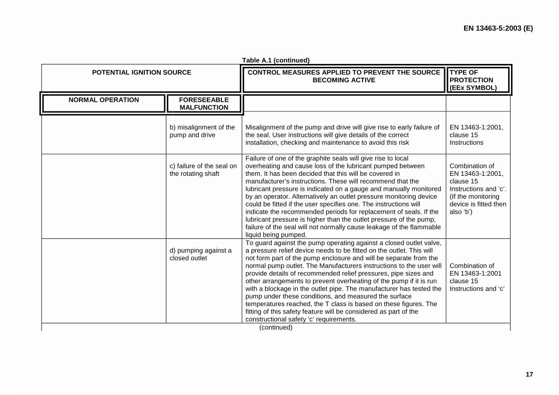
Table A.1 (continued)
POTENTIAL IGNITION SOURCE CONTROL MEASURES APPLIED TO PREVENT THE SOURCEBECOMING ACTIVE
TYPE OFPROTECTION(EEx SYMBOL)
NORMAL OPERATION FORESEEABLEMALFUNCTION
b) misalignment of thepump and drive
Misalignment of the pump and drive will give rise to early failure ofthe seal. User instructions will give details of the correctinstallation, checking and maintenance to avoid this risk
EN 13463-1:2001,clause 15Instructions
c) failure of the seal onthe rotating shaft
Failure of one of the graphite seals will give rise to localoverheating and cause loss of the lubricant pumped betweenthem. It has been decided that this will be covered inmanufacturer’s instructions. These will recommend that thelubricant pressure is indicated on a gauge and manually monitoredby an operator. Alternatively an outlet pressure monitoring devicecould be fitted if the user specifies one. The instructions willindicate the recommended periods for replacement of seals. If thelubricant pressure is higher than the outlet pressure of the pump,failure of the seal will not normally cause leakage of the flammableliquid being pumped.
Combination ofEN 13463-1:2001,clause 15Instructions and ‘c’.(If the monitoringdevice is fitted thenalso ‘b’)
d) pumping against aclosed outlet
To guard against the pump operating against a closed outlet valve,a pressure relief device needs to be fitted on the outlet. This willnot form part of the pump enclosure and will be separate from thenormal pump outlet. The Manufacturers instructions to the user willprovide details of recommended relief pressures, pipe sizes andother arrangements to prevent overheating of the pump if it is runwith a blockage in the outlet pipe. The manufacturer has tested thepump under these conditions, and measured the surfacetemperatures reached, the T class is based on these figures. Thefitting of this safety feature will be considered as part of theconstructional safety ‘c’ requirements.
Combination ofEN 13463-1:2001clause 15Instructions and ‘c’
(continued)
EN 13463-5:2003 (E)
18
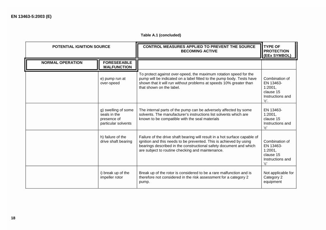
Table A.1 (concluded)
POTENTIAL IGNITION SOURCE CONTROL MEASURES APPLIED TO PREVENT THE SOURCEBECOMING ACTIVE
TYPE OFPROTECTION(EEx SYMBOL)
NORMAL OPERATION FORESEEABLEMALFUNCTION
e) pump run atover-speed
To protect against over-speed, the maximum rotation speed for thepump will be indicated on a label fitted to the pump body. Tests haveshown that it will run without problems at speeds 10% greater thanthat shown on the label.
Combination ofEN 13463-1:2001,clause 15Instructions and‘c’.
g) swelling of someseals in thepresence ofparticular solvents
The internal parts of the pump can be adversely affected by somesolvents. The manufacturer’s instructions list solvents which areknown to be compatible with the seal materials
EN 13463-1:2001,clause 15Instructions and‘c’
h) failure of thedrive shaft bearing
Failure of the drive shaft bearing will result in a hot surface capable ofignition and this needs to be prevented. This is achieved by usingbearings described in the constructional safety document and whichare subject to routine checking and maintenance.
Combination ofEN 13463-1:2001,clause 15Instructions and‘c’
i) break up of theimpeller rotor
Break up of the rotor is considered to be a rare malfunction and istherefore not considered in the risk assessment for a category 2pump.
Not applicable forCategory 2equipment
EN 13463-5:2003 (E)
19
A.2 Ignition hazard assessment relating to a Group II, category 1 stirrer
The risk assessment performed in accordance with 5.2 of EN 13463-1:2001 has indicated that the proposed stirrer issuitable equipment for protection by 'Constructional Safety ' as Group II, category 1 equipment. This is because thefundamental requirement of such protection can be met. In that, the stirrer does not contain ignition sources in normaloperation and foreseeable malfunctions. Furthermore, by good design, construction, selection of materials andmaintenance procedures, the risk of igniting sources being created can be made so low that they are unlikely to occur,even during rare malfunction or with two faults on the stirrer.
The stirrer is operated in a closed stirring vessel. If the clearances between the wall of the stirring vessel and thestirring element are large enough to avoid rubbing contact between the stirring element and the wall, the only criticalpoint is the shaft passage through the top of the vessel. Other possible ignition sources which can occur inside thevessel such as electrostatic charging of the stirred liquid are outside the scope of this standard but a warning shouldbe given in the information for use.
As has been mentioned above, the shaft passage through the wall of the vessel needs to be sealed by a doubleacting slide ring sealing preferably with secured sealing liquid. Experience has shown, that for this type of sealingeven a rare failure leading to ignition is not to be expected.
An alternative design would be a shaft passage where the ring gap between shaft and wall is so small that it isflameproof for the respective gas group. In this case a careful design of the shaft bearing is required to ensure thatrubbing contact of the shaft can reasonably be excluded even as a rare event.
The shaft duct above the ring gap needs to be constructed with a gap so that ventilation near the ring gap is provided.
A.3 Ignition hazard assessment relating to a Group II, category 1 compressed air motorused for tank cleaning
The working principle of a compressed air engine, is that expanding compressed air releases its potential energy topropel the rotating turbine blades, which in turn provide output power via the gear mechanism to the output shaft.Generally, the compressed air input to the engine is obtained from a high pressure network supplied from a placeoutside the potentially explosive atmosphere. The gears change the output drive shaft speed and torque to thatrequired by the load being driven. The engine is constructed so that its maximum working pressure is well in excess ofthe nominal pressure of the compressed air network. This results in an adequately robust engine, which has its mainmoving parts (rotor and stator) continuously flushed and purged with clean air both during normal operation and alsoin the case of expected faults on the rotor blades.
The risk assessment performed in accordance with 5.2 of EN 13463-1:2001 which also considers the power andspeed of the equipment has indicated that the proposed compressed air engine is suitable equipment for protectionby 'Constructional Safety ' as Group II, category 1 equipment. This is because the fundamental requirement of suchprotection can be met. In that, the engine does not contain ignition sources in normal operation and foreseeablemalfunctions. Furthermore, by good design, construction, selection of materials and maintenance procedures, the riskof igniting sources being created can be made so low that they are unlikely to occur, even in the case of raremalfunctions or with two faults on the engine and therefore the engine meets the requirements of category 1.
The risk assessment for category 1 has identified that the vulnerable engine parts needing consideration are, thematerials used for the outer enclosure and the output shaft (which are the parts exposed to the potentially explosiveatmosphere) and the internal moving parts which may fail due to insufficient strength, fatigue, or contamination bypollutants which can act as an ignition source.
As described by the general gas laws of physics, the temperature of compressed air reduces as it expands throughthe engine. This cooling effect can therefore be taken into account and put to good use, to limit the operatingtemperature of other parts of the engine, such as the exhaust airways and parts where frictional heat is produced bymoving parts.
The materials used in the construction of the outer enclosure and output shaft are steel or stainless steel, which isnot subject to frictional sparking or electrostatic discharge if grounded properly. Due to the fact that the internalparts (e.g. rotor and stator) are flushed with the expanding air they do not come into contact with the potentiallyexplosive atmosphere and therefore need no special attention with respect to spark ignition risk. The internal partscan be made of any material, as long as it is strong enough to meet the operational performance requirements andprovides some safety factor against failure due to mechanical forces. If overloads create inadmissible hot surfaces atorque limiting device or other suitable devices can be applied.

EN 13463-5:2003 (E)
20
The correct selection of main shaft bearings, with well tried and proven reliability, coupled with the use of highviscosity grease as a lubricant inside an 'IP 54' rated bearing housing prevents overheating and also, dust andsplashing water entering to pollute the lubricant. The risk of premature bearing failure in service is thereby reduced.
The gear drives are contained in a dust proof and watertight enclosure. Either they are life-time lubricated andpermanently flushed with the expanding air or they are submerged in a protective lubricant which does not readilysupport combustion. In the latter case the amount of lubricant needs to be monitored or checked regularly (see EN13463-8). If the gearbox lubrication is a protective measure the 'User Instructions' should contain information that itrelies on manual checking and there is also a slight risk of unpredictable malfunctions (e.g. failure of a turbine blade,or bearing, also overloading or over-speeding of the output shaft).
EN 13463-5:2003 (E)
21
Annex B(normative)
Test requirements
B.1 "Dry run" test for lubricated sealing arrangements
The test attempts to simulate the heating which can occur when the lubrication provided for lubricated type sealingelements, between fixed and moving parts of equipment, is lost. Examples of the sealing arrangements concerned,are gasketed seals, shell type seals and other similar seals used for sliding or rotating shafts.
Before the test, remove the lubricant without the use of a solvent so that minimum residual lubrication is retained.Then subject the sealing arrangement to a "dry run" test of at least one hour with the moving part operating at itsmaximum normal operating speed.
Measure the temperature on the fixed part of the equipment as near as possible to the place where the seal makescontact with the moving parts. For example, an accurate determination can usually be made by inserting athermocouple into a small hole drilled at an angle near the seal so that it extends underneath the sealing element.Towards the end of the test several temperature readings may need to be taken to ensure that a final 'steady state'temperature has been attained. Note the temperature readings together with the ambient temperature and the speedof moving part during the test.
B.2 Type test for determining the maximum engaging time of clutch assembly
B.2.1 Apparatus
B.2.1.1 One clutch assembly – of the type intended to be used in the potentially explosive atmosphere. If theclutch assembly forms part of series having different input and output characteristics, select the assembly designedto transmit the largest amount of power and torque from its input shaft to its output shaft.
NOTE If the clutch assembly is fitted with an overload prevention device, such as a shear pin (for friction pad types), orfusible link/plug (for liquid filled types), this can need to be defeated during the test to prevent it effecting the results.
B.2.1.2 Temperature sensor(s) - able to measure temperatures up to and including at least the maximum surfacetemperature for the explosive atmosphere in which the clutch is intended to be used. The sensor(s) also need to becapable of measuring the temperature of fixed and moving parts exposed to the surrounding atmosphere. Suitablesensor(s) are for example specially calibrated infra-red heat detectors, arranged to measure the actual temperature ofmoving parts without being mechanically connected to them.
B.2.1.3 Drive motor – able to transmit the clutch assembly manufacturer's maximum recommended inputpower and torque to the assembly.
B.2.1.4 Locking mechanism – able to prevent the output shaft of the clutch assembly from rotating when themanufacturer's maximum recommended input drive power and torque is applied to the input shaft.
B.2.1.5 Timer/recorder - arranged to start when the drive power is first applied to the input shaft and stoppedwhen the temperature sensor detects that a part of the assembly has attained the maximum surface temperatureallowed for the atmosphere.
B.2.1.6 Conditioning chamber – able to condition the clutch assembly whilst it is connected to the drive motorand locking mechanism.
EN 13463-5:2003 (E)
22
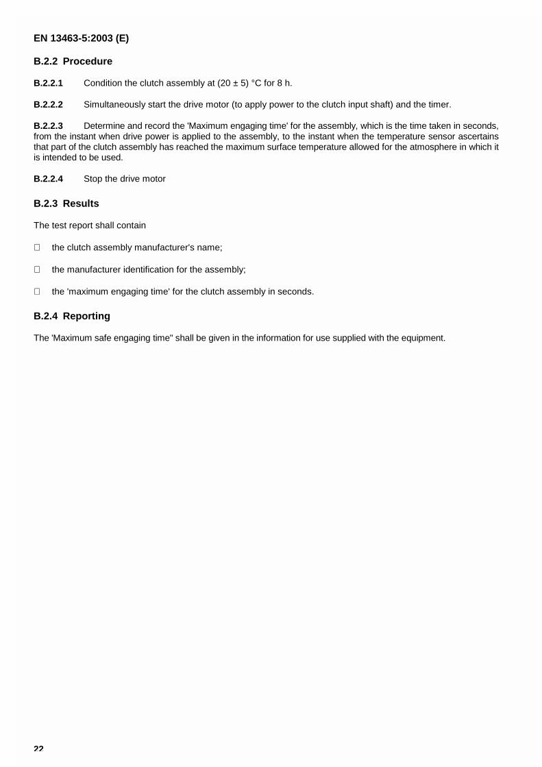
B.2.2 Procedure
B.2.2.1 Condition the clutch assembly at (20 ± 5) °C for 8 h.
B.2.2.2 Simultaneously start the drive motor (to apply power to the clutch input shaft) and the timer.
B.2.2.3 Determine and record the 'Maximum engaging time' for the assembly, which is the time taken in seconds,from the instant when drive power is applied to the assembly, to the instant when the temperature sensor ascertainsthat part of the clutch assembly has reached the maximum surface temperature allowed for the atmosphere in which itis intended to be used.
B.2.2.4 Stop the drive motor
B.2.3 Results
The test report shall contain
the clutch assembly manufacturer's name;
the manufacturer identification for the assembly;
the 'maximum engaging time' for the clutch assembly in seconds.
B.2.4 Reporting
The 'Maximum safe engaging time" shall be given in the information for use supplied with the equipment.
EN 13463-5:2003 (E)
23
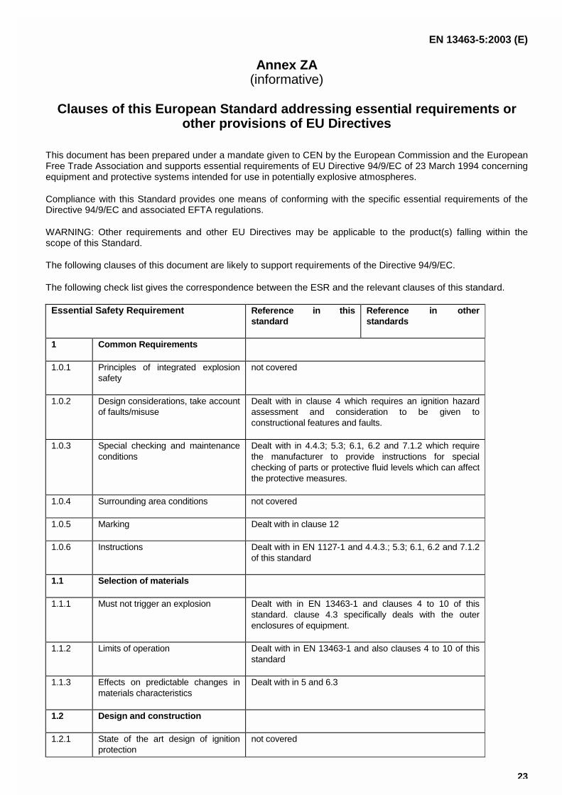
Annex ZA(informative)
Clauses of this European Standard addressing essential requirements orother provisions of EU Directives
This document has been prepared under a mandate given to CEN by the European Commission and the EuropeanFree Trade Association and supports essential requirements of EU Directive 94/9/EC of 23 March 1994 concerningequipment and protective systems intended for use in potentially explosive atmospheres.
Compliance with this Standard provides one means of conforming with the specific essential requirements of theDirective 94/9/EC and associated EFTA regulations.
WARNING: Other requirements and other EU Directives may be applicable to the product(s) falling within thescope of this Standard.
The following clauses of this document are likely to support requirements of the Directive 94/9/EC.
The following check list gives the correspondence between the ESR and the relevant clauses of this standard.
Essential Safety Requirement Reference in thisstandard
Reference in otherstandards
1 Common Requirements
1.0.1 Principles of integrated explosionsafety
not covered
1.0.2 Design considerations, take accountof faults/misuse
Dealt with in clause 4 which requires an ignition hazardassessment and consideration to be given toconstructional features and faults.
1.0.3 Special checking and maintenanceconditions
Dealt with in 4.4.3; 5.3; 6.1, 6.2 and 7.1.2 which requirethe manufacturer to provide instructions for specialchecking of parts or protective fluid levels which can affectthe protective measures.
1.0.4 Surrounding area conditions not covered
1.0.5 Marking Dealt with in clause 12
1.0.6 Instructions Dealt with in EN 1127-1 and 4.4.3.; 5.3; 6.1, 6.2 and 7.1.2of this standard
1.1 Selection of materials
1.1.1 Must not trigger an explosion Dealt with in EN 13463-1 and clauses 4 to 10 of thisstandard. clause 4.3 specifically deals with the outerenclosures of equipment.
1.1.2 Limits of operation Dealt with in EN 13463-1 and also clauses 4 to 10 of thisstandard
1.1.3 Effects on predictable changes inmaterials characteristics
Dealt with in 5 and 6.3
1.2 Design and construction
1.2.1 State of the art design of ignitionprotection
not covered
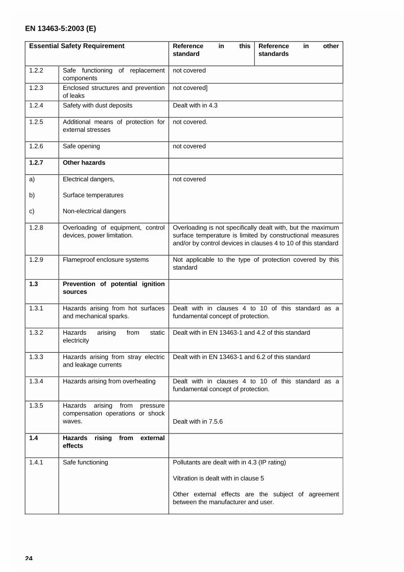
EN 13463-5:2003 (E)
24
Essential Safety Requirement Reference in thisstandard
Reference in otherstandards
1.2.2 Safe functioning of replacementcomponents
not covered
1.2.3 Enclosed structures and preventionof leaks
not covered]
1.2.4 Safety with dust deposits Dealt with in 4.3
1.2.5 Additional means of protection forexternal stresses
not covered.
1.2.6 Safe opening not covered
1.2.7 Other hazards
a)
b)
c)
Electrical dangers,
Surface temperatures
Non-electrical dangers
not covered
1.2.8 Overloading of equipment, controldevices, power limitation.
Overloading is not specifically dealt with, but the maximumsurface temperature is limited by constructional measuresand/or by control devices in clauses 4 to 10 of this standard
1.2.9 Flameproof enclosure systems Not applicable to the type of protection covered by thisstandard
1.3 Prevention of potential ignitionsources
1.3.1 Hazards arising from hot surfacesand mechanical sparks.
Dealt with in clauses 4 to 10 of this standard as afundamental concept of protection.
1.3.2 Hazards arising from staticelectricity
Dealt with in EN 13463-1 and 4.2 of this standard
1.3.3 Hazards arising from stray electricand leakage currents
Dealt with in EN 13463-1 and 6.2 of this standard
1.3.4 Hazards arising from overheating Dealt with in clauses 4 to 10 of this standard as afundamental concept of protection.
1.3.5 Hazards arising from pressurecompensation operations or shockwaves. Dealt with in 7.5.6
1.4 Hazards rising from externaleffects
1.4.1 Safe functioning Pollutants are dealt with in 4.3 (IP rating)
Vibration is dealt with in clause 5
Other external effects are the subject of agreementbetween the manufacturer and user.
EN 13463-5:2003 (E)
25
Essential Safety Requirement Reference in thisstandard
Reference in otherstandards
1.4.2 Mechanical and thermal stressesand withstanding attack byforeseeable aggressive substances
Dealt with in 4.2 and 6.3 by applying good engineeringpractice. Resistance to chemical attack is subject toagreement between the manufacturer and user.
1.5 Requirements in respect ofsafety-related devices
1.5.1 Independent function of safetydevices of measurement andcontrol. Fail safe principles forelectric circuits. Safety relatedswitches independent of softwareand command
Safety Related Devices are not intended to be within thescope of this standard
1.5.2 Safety device failure Safety Related Devices are not intended to be within thescope of this standard
1.5.3 Emergency stop controls Safety Related Devices are not intended to be within thescope of this standard
1.5.4 Control and display units Safety Related Devices are not intended to be within thescope of this standard
1.5.5 Requirements in respect of deviceswith a measuring function forignition protection
Safety Related Devices are not intended to be within thescope of this standard
1.5.6 Checking accuracy of measuringdevices
Safety Related Devices are not intended to be within thescope of this standard
1.5.7 Measuring device safety factor Safety Related Devices are not intended to be within thescope of this standard
1.5.8 Risks arising from software Safety Related Devices are not intended to be within thescope of this standard
1.6 Integration of safetyrequirements relating to thesystem
1.6.1 Manual override Integrated systems are not intended to be within the scopeof this standard.
1.6.2 Emergency shutdown system Integrated systems are not intended to be within the scopeof this standard.
1.6.3 Hazards arising from power failure Integrated systems are not intended to be within the scopeof this standard.
1.6.4 Hazards arising from connections Integrated systems are not intended to be within the scopeof this standard.
1.6.5 Placing of warning devices as partsof equipment
Integrated systems are not intended to be within the scopeof this standard.
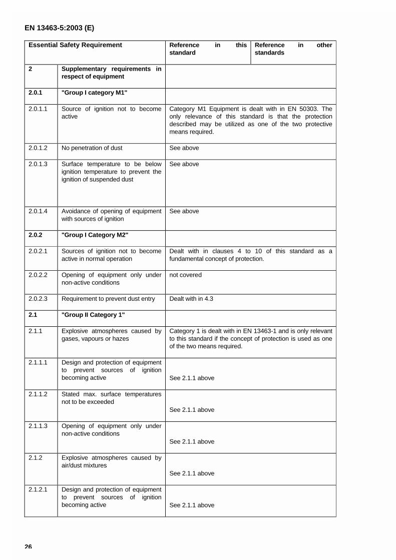
EN 13463-5:2003 (E)
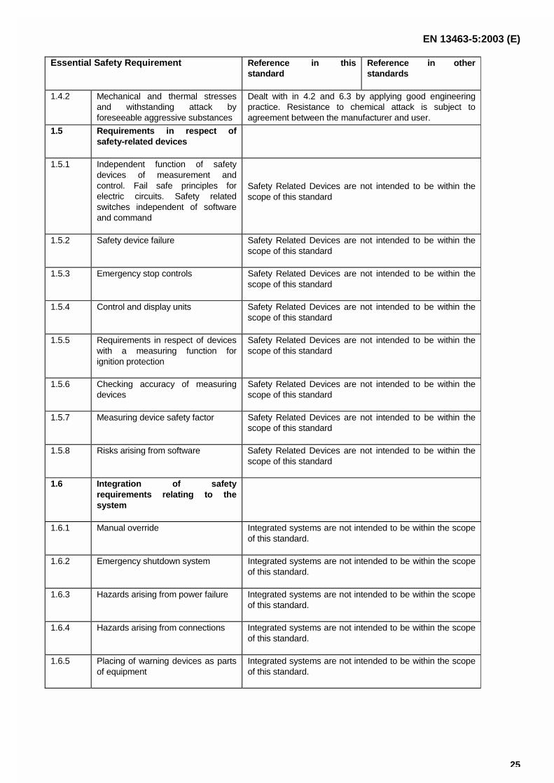
26
Essential Safety Requirement Reference in thisstandard
Reference in otherstandards
2 Supplementary requirements inrespect of equipment
2.0.1 "Group I category M1"
2.0.1.1 Source of ignition not to becomeactive
Category M1 Equipment is dealt with in EN 50303. Theonly relevance of this standard is that the protectiondescribed may be utilized as one of the two protectivemeans required.
2.0.1.2 No penetration of dust See above
2.0.1.3 Surface temperature to be belowignition temperature to prevent theignition of suspended dust
See above
2.0.1.4 Avoidance of opening of equipmentwith sources of ignition
See above
2.0.2 "Group I Category M2"
2.0.2.1 Sources of ignition not to becomeactive in normal operation
Dealt with in clauses 4 to 10 of this standard as afundamental concept of protection.
2.0.2.2 Opening of equipment only undernon-active conditions
not covered
2.0.2.3 Requirement to prevent dust entry Dealt with in 4.3
2.1 "Group II Category 1"
2.1.1 Explosive atmospheres caused bygases, vapours or hazes
Category 1 is dealt with in EN 13463-1 and is only relevantto this standard if the concept of protection is used as oneof the two means required.
2.1.1.1 Design and protection of equipmentto prevent sources of ignitionbecoming active See 2.1.1 above
2.1.1.2 Stated max. surface temperaturesnot to be exceeded
See 2.1.1 above
2.1.1.3 Opening of equipment only undernon-active conditions
See 2.1.1 above
2.1.2 Explosive atmospheres caused byair/dust mixtures
See 2.1.1 above
2.1.2.1 Design and protection of equipmentto prevent sources of ignitionbecoming active See 2.1.1 above
EN 13463-5:2003 (E)
27
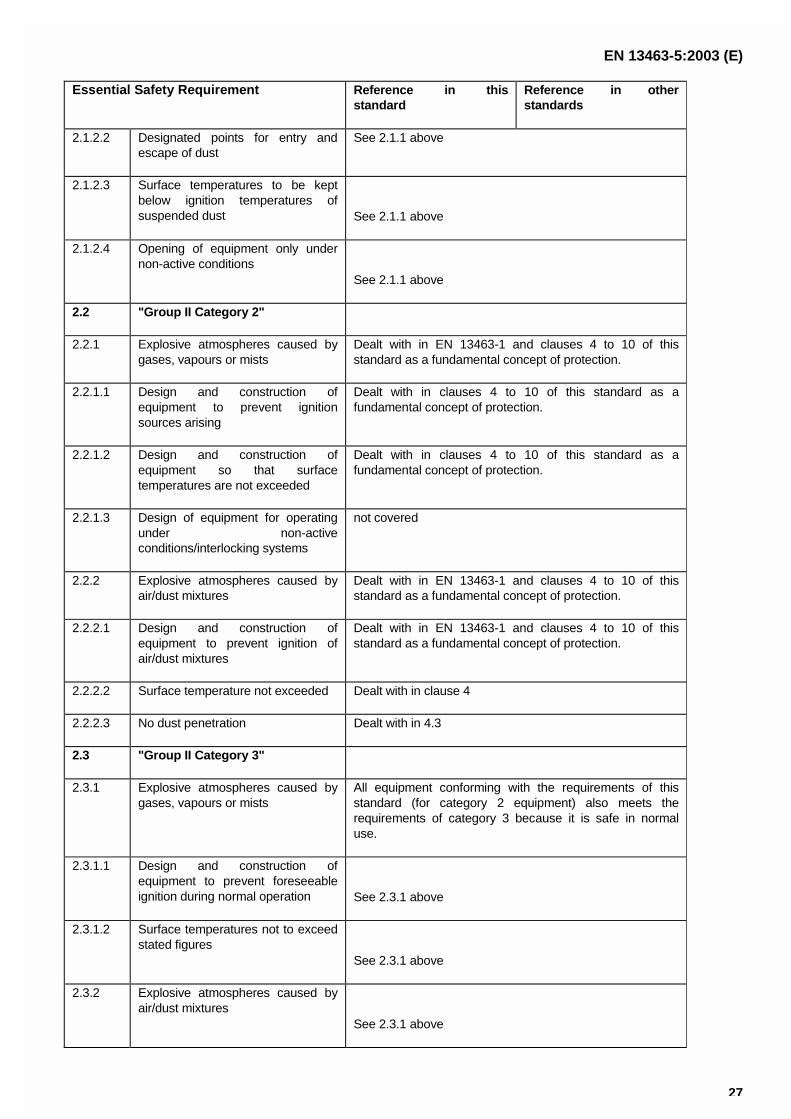
Essential Safety Requirement Reference in thisstandard
Reference in otherstandards
2.1.2.2 Designated points for entry andescape of dust
See 2.1.1 above
2.1.2.3 Surface temperatures to be keptbelow ignition temperatures ofsuspended dust See 2.1.1 above
2.1.2.4 Opening of equipment only undernon-active conditions
See 2.1.1 above
2.2 "Group II Category 2"
2.2.1 Explosive atmospheres caused bygases, vapours or mists
Dealt with in EN 13463-1 and clauses 4 to 10 of thisstandard as a fundamental concept of protection.
2.2.1.1 Design and construction ofequipment to prevent ignitionsources arising
Dealt with in clauses 4 to 10 of this standard as afundamental concept of protection.
2.2.1.2 Design and construction ofequipment so that surfacetemperatures are not exceeded
Dealt with in clauses 4 to 10 of this standard as afundamental concept of protection.
2.2.1.3 Design of equipment for operatingunder non-activeconditions/interlocking systems
not covered
2.2.2 Explosive atmospheres caused byair/dust mixtures
Dealt with in EN 13463-1 and clauses 4 to 10 of thisstandard as a fundamental concept of protection.
2.2.2.1 Design and construction ofequipment to prevent ignition ofair/dust mixtures
Dealt with in EN 13463-1 and clauses 4 to 10 of thisstandard as a fundamental concept of protection.
2.2.2.2 Surface temperature not exceeded Dealt with in clause 4
2.2.2.3 No dust penetration Dealt with in 4.3
2.3 "Group II Category 3"
2.3.1 Explosive atmospheres caused bygases, vapours or mists
All equipment conforming with the requirements of thisstandard (for category 2 equipment) also meets therequirements of category 3 because it is safe in normaluse.
2.3.1.1 Design and construction ofequipment to prevent foreseeableignition during normal operation See 2.3.1 above
2.3.1.2 Surface temperatures not to exceedstated figures
See 2.3.1 above
2.3.2 Explosive atmospheres caused byair/dust mixtures
See 2.3.1 above
EN 13463-5:2003 (E)
28
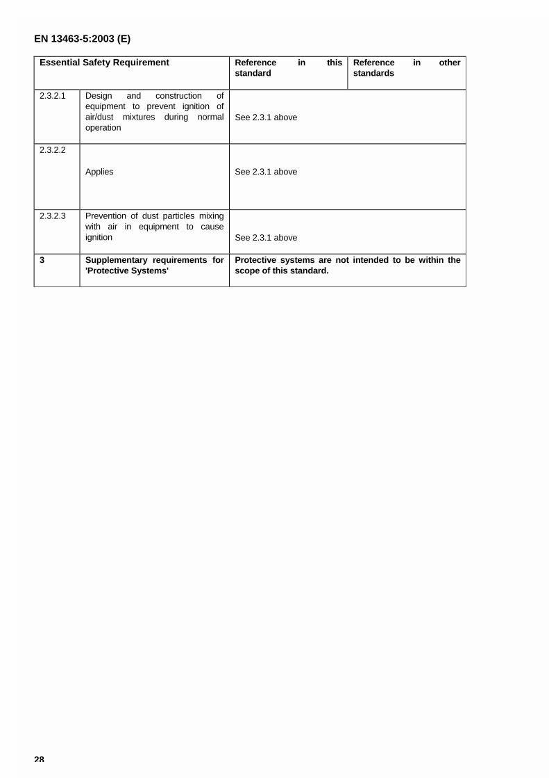
Essential Safety Requirement Reference in thisstandard
Reference in otherstandards
2.3.2.1 Design and construction ofequipment to prevent ignition ofair/dust mixtures during normaloperation
See 2.3.1 above
2.3.2.2
Applies See 2.3.1 above
2.3.2.3 Prevention of dust particles mixingwith air in equipment to causeignition See 2.3.1 above
3 Supplementary requirements for'Protective Systems'
Protective systems are not intended to be within thescope of this standard.
EN 13463-5:2003 (E)
29
Bibliography
EN 1710, Equipment and components intended for use in potentially explosive atmospheres in mines.
EN 50303:2000 Group I, category M1 equipment intended to remain functional in atmospheres endangered byfiredamp and/or coal dust.
ISO 281:1990, Rolling bearings - Dynamic load ratings and rating life.
ISO 1813, Belt drives - V-ribbed belts, joined V-belts and V-belts including wide section belts and hexagonal belts -Electrical conductivity of antistatic belts: Characteristics and methods of test.
IEC 60079-4, Electrical apparatus for explosive gas atmospheres - Part 4 : Method of test for ignition temperature.
CENELEC Technical Report CLC/TR 50404:2003-06, Electrostatics – Code of practise for the avoidance ofhazards due to static electricity.
Requirements and tests applicable to fire-resistant hydraulic fluids used for power transmission and control(hydrostatic and hydrokinetic), seventh edition, doc. N° 4746/10/91 EN, Luxembourg, April 1994.
BS EN 13463-5:2003
BSI
389 Chiswick High Road
London
W4 4AL
BSI — British Standards InstitutionBSI is the independent national body responsible for preparing British Standards. It presents the UK view on standards in Europe and at the international level. It is incorporated by Royal Charter.
Revisions
British Standards are updated by amendment or revision. Users of British Standards should make sure that they possess the latest amendments or editions.
It is the constant aim of BSI to improve the quality of our products and services. We would be grateful if anyone finding an inaccuracy or ambiguity while using this British Standard would inform the Secretary of the technical committee responsible, the identity of which can be found on the inside front cover. Tel: +44 (0)20 8996 9000. Fax: +44 (0)20 8996 7400.
BSI offers members an individual updating service called PLUS which ensures that subscribers automatically receive the latest editions of standards.
Buying standards
Orders for all BSI, international and foreign standards publications should be addressed to Customer Services. Tel: +44 (0)20 8996 9001. Fax: +44 (0)20 8996 7001. Email: [email protected]. Standards are also available from the BSI website at http://www.bsi-global.com.
In response to orders for international standards, it is BSI policy to supply the BSI implementation of those that have been published as British Standards, unless otherwise requested.
Information on standards
BSI provides a wide range of information on national, European and international standards through its Library and its Technical Help to Exporters Service. Various BSI electronic information services are also available which give details on all its products and services. Contact the Information Centre. Tel: +44 (0)20 8996 7111. Fax: +44 (0)20 8996 7048. Email: [email protected].
Subscribing members of BSI are kept up to date with standards developments and receive substantial discounts on the purchase price of standards. For details of these and other benefits contact Membership Administration. Tel: +44 (0)20 8996 7002. Fax: +44 (0)20 8996 7001. Email: [email protected].
Information regarding online access to British Standards via British Standards Online can be found at http://www.bsi-global.com/bsonline.
Further information about BSI is available on the BSI website at http://www.bsi-global.com.
Copyright
Copyright subsists in all BSI publications. BSI also holds the copyright, in the UK, of the publications of the international standardization bodies. Except as permitted under the Copyright, Designs and Patents Act 1988 no extract may be reproduced, stored in a retrieval system or transmitted in any form or by any means – electronic, photocopying, recording or otherwise – without prior written permission from BSI.
This does not preclude the free use, in the course of implementing the standard, of necessary details such as symbols, and size, type or grade designations. If these details are to be used for any other purpose than implementation then the prior written permission of BSI must be obtained.
Details and advice can be obtained from the Copyright & Licensing Manager. Tel: +44 (0)20 8996 7070. Fax: +44 (0)20 8996 7553. Email: [email protected].