Embed Size (px)
Citation preview
EN 13445-3:2002 (E) Issue 30 (2008-03)
4a
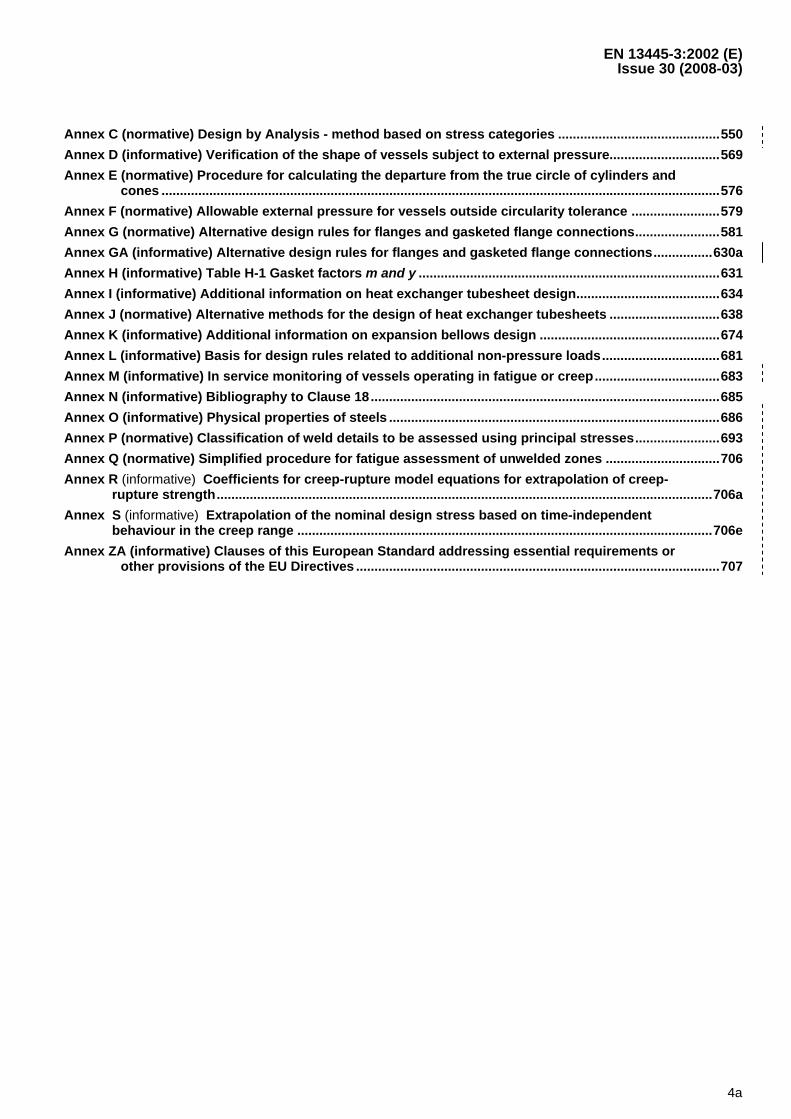
Annex C (normative) Design by Analysis - method based on stress categories ............................................550 Annex D (informative) Verification of the shape of vessels subject to external pressure..............................569 Annex E (normative) Procedure for calculating the departure from the true circle of cylinders and
cones ........................................................................................................................................................576 Annex F (normative) Allowable external pressure for vessels outside circularity tolerance ........................579 Annex G (normative) Alternative design rules for flanges and gasketed flange connections.......................581 Annex GA (informative) Alternative design rules for flanges and gasketed flange connections................630a Annex H (informative) Table H-1 Gasket factors m and y ..................................................................................631 Annex I (informative) Additional information on heat exchanger tubesheet design.......................................634 Annex J (normative) Alternative methods for the design of heat exchanger tubesheets ..............................638 Annex K (informative) Additional information on expansion bellows design .................................................674 Annex L (informative) Basis for design rules related to additional non-pressure loads................................681 Annex M (informative) In service monitoring of vessels operating in fatigue or creep..................................683 Annex N (informative) Bibliography to Clause 18...............................................................................................685 Annex O (informative) Physical properties of steels ..........................................................................................686 Annex P (normative) Classification of weld details to be assessed using principal stresses.......................693 Annex Q (normative) Simplified procedure for fatigue assessment of unwelded zones ...............................706 Annex R (informative) Coefficients for creep-rupture model equations for extrapolation of creep-
rupture strength.......................................................................................................................................706a Annex S (informative) Extrapolation of the nominal design stress based on time-independent
behaviour in the creep range .................................................................................................................706e Annex ZA (informative) Clauses of this European Standard addressing essential requirements or
other provisions of the EU Directives ...................................................................................................707


EN 13445-3:2002 (E) Issue 30 (2008-03)
5
Foreword
This document (EN 13445-3:2002, EN 13445-3:2002/A4:2005, EN 13445-3:2002/A5:2006, EN 13445-3:2002/A6:2006, EN 13445-3:2002/A8:2006, EN 13445-3:2002/A11:2006, EN 13445-3:2002/A2:2007, EN 13445-3:2002/A3:2007, EN 13445-3:2002/A1:2007, EN 13445-3:2002/A17:2007 and EN 13445-3:2002/A10:2008) has been prepared by Technical Committee CEN/TC 54 “Unfired pressure vessels”, the secretariat of which is held by BSI.
EN 13445-3:2002 shall be given the status of a national standard, either by publication of an identical text or by endorsement, at the latest by November 2002, and conflicting national standards shall be withdrawn at the latest by November 2002. EN 13445-3:2002/A4:2005 shall be given the status of a national standard, either by publication of an identical text or by endorsement, at the latest by January 2006, and conflicting national standards shall be withdrawn at the latest by January 2006. EN 13445-3:2002/A5:2006 and EN 13445-3:2002/A6:2006 shall be given the status of a national standard, either by publication of an identical text or by endorsement, at the latest by August 2006, and conflicting national standards shall be withdrawn at the latest by August 2006. EN 13445-3:2002/A8:2006 shall be given the status of a national standard, either by publication of an identical text or by endorsement, at the latest by October 2006, and conflicting national standards shall be withdrawn at the latest by October 2006. EN 13445-3:2002/A11:2006 shall be given the status of a national standard, either by publication of an identical text or by endorsement, at the latest by June 2007, and conflicting national standards shall be withdrawn at the latest by June 2007. EN 13445-3:2002/A2:2007 shall be given the status of a national standard, either by publication of an identical text or by endorsement, at the latest by October 2007, and conflicting national standards shall be withdrawn at the latest by October 2007. EN 13445-3:2002/A3:2007 shall be given the status of a national standard, either by publication of an identical text or by endorsement, at the latest by October 2007, and conflicting national standards shall be withdrawn at the latest by October 2007. EN 13445-3:2002/A1:2007 shall be given the status of a national standard, either by publication of an identical text or by endorsement, at the latest by December 2007, and conflicting national standards shall be withdrawn at the latest by December 2007. EN 13445-3:2002/A17:2007 shall be given the status of a national standard, either by publication of an identical text or by endorsement, at the latest by April 2008, and conflicting national standards shall be withdrawn at the latest by April 2008. EN 13445-3:2002/A10:2008 shall be given the status of a national standard, either by publication of an identical text or by endorsement, at the latest by September 2008, and conflicting national standards shall be withdrawn at the latest by September 2008.
NOTE Issue 25 of EN 13445-3:2002 does not contain the specific provisions of EN 13445-3:2002/A2:2007 concerning non-destructive testing of welded joints and final assessment for vessels designed by experimental methods, which are incorporated in issue 25 of EN 13445-5:2002.
Attention is drawn to the possibility that some of the elements of this document may be the subject of patent rights. CEN [and/or CENELEC] shall not be held responsible for identifying any or all such patent rights.
This document has been prepared under a mandate given to CEN by the European Commission and the European Free Trade Association, and supports essential requirements of EU Directive 97/23/EC.
For relationship with EU Directive(s), see informative Annex ZA, which is an integral part of this document.
In this standard the Annexes A, B, C, E, F, G, J, P and Q are normative and the Annexes D, H, I, K, L, M, N, O, R and S are informative.
This European Standard consists of the following Parts:
― Part 1: General. ― Part 2: Materials. ― Part 3: Design. ― Part 4: Fabrication. ― Part 5: Inspection and Testing. ― Part 6: Requirements for the design and fabrication of pressure vessels and pressure parts constructed from spheroidal graphite cast iron. ― CR 13445-7, Unfired pressure vessels - Part 7: Guidance on the use of conformity assessment procedures.
According to the CEN/CENELEC Internal Regulations, the national standards organizations of the following countries are bound to implement this European Standard: Austria, Belgium, Bulgaria, Cyprus, Czech Republic, Denmark, Estonia, Finland, France, Germany, Greece, Hungary, Iceland, Ireland, Italy, Latvia, Lithuania, Luxembourg, Malta, Netherlands, Norway, Poland, Portugal, Romania, Slovakia, Slovenia, Spain, Sweden, Switzerland and United Kingdom.
EN 13445-3:2002 (E) Issue 27 (2007-06)
6
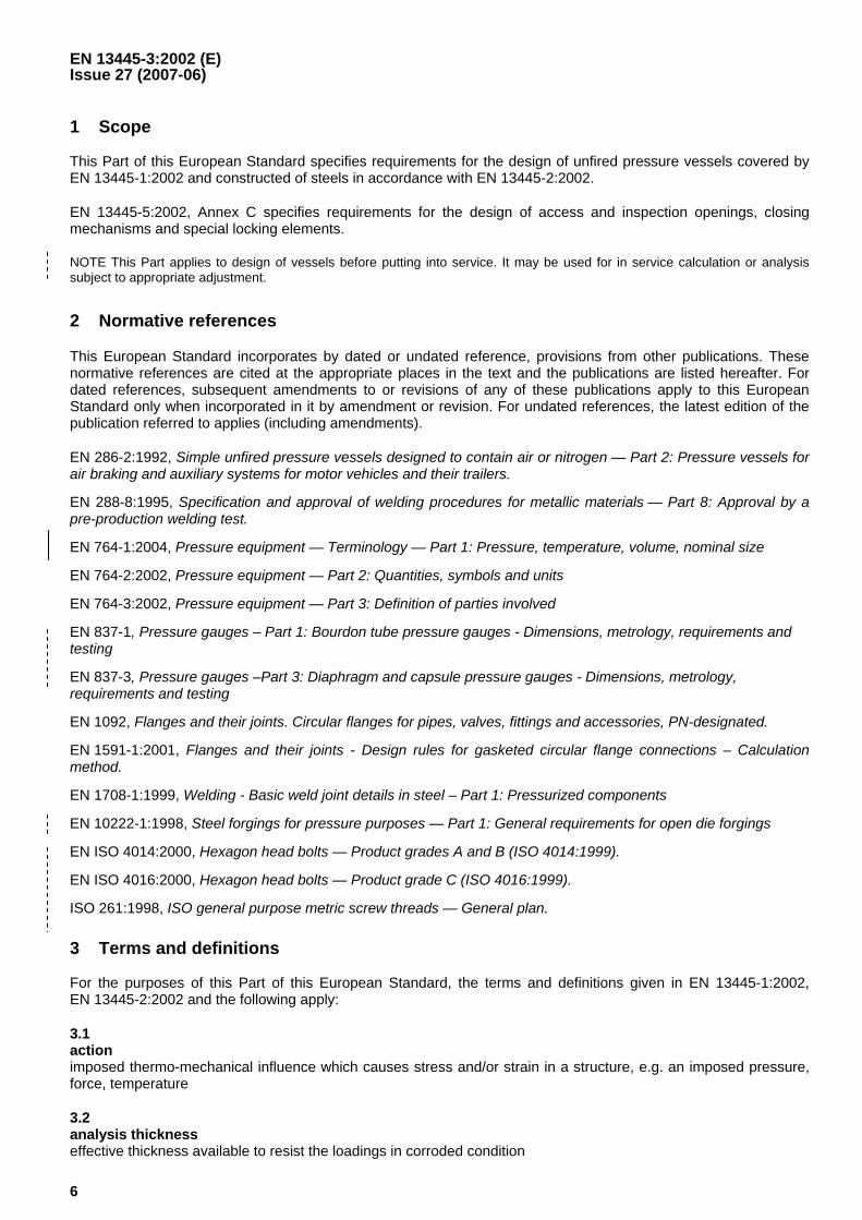
1 Scope
This Part of this European Standard specifies requirements for the design of unfired pressure vessels covered by EN 13445-1:2002 and constructed of steels in accordance with EN 13445-2:2002.
EN 13445-5:2002, Annex C specifies requirements for the design of access and inspection openings, closing mechanisms and special locking elements.
NOTE This Part applies to design of vessels before putting into service. It may be used for in service calculation or analysis subject to appropriate adjustment.
2 Normative references
This European Standard incorporates by dated or undated reference, provisions from other publications. These normative references are cited at the appropriate places in the text and the publications are listed hereafter. For dated references, subsequent amendments to or revisions of any of these publications apply to this European Standard only when incorporated in it by amendment or revision. For undated references, the latest edition of the publication referred to applies (including amendments).
EN 286-2:1992, Simple unfired pressure vessels designed to contain air or nitrogen — Part 2: Pressure vessels for air braking and auxiliary systems for motor vehicles and their trailers.
EN 288-8:1995, Specification and approval of welding procedures for metallic materials — Part 8: Approval by a pre-production welding test.
EN 764-1:2004, Pressure equipment — Terminology — Part 1: Pressure, temperature, volume, nominal size
EN 764-2:2002, Pressure equipment — Part 2: Quantities, symbols and units
EN 764-3:2002, Pressure equipment — Part 3: Definition of parties involved
EN 837-1, Pressure gauges – Part 1: Bourdon tube pressure gauges - Dimensions, metrology, requirements and testing
EN 837-3, Pressure gauges –Part 3: Diaphragm and capsule pressure gauges - Dimensions, metrology, requirements and testing
EN 1092, Flanges and their joints. Circular flanges for pipes, valves, fittings and accessories, PN-designated.
EN 1591-1:2001, Flanges and their joints - Design rules for gasketed circular flange connections – Calculation method.
EN 1708-1:1999, Welding - Basic weld joint details in steel – Part 1: Pressurized components
EN 10222-1:1998, Steel forgings for pressure purposes — Part 1: General requirements for open die forgings
EN ISO 4014:2000, Hexagon head bolts — Product grades A and B (ISO 4014:1999).
EN ISO 4016:2000, Hexagon head bolts — Product grade C (ISO 4016:1999).
ISO 261:1998, ISO general purpose metric screw threads — General plan.
3 Terms and definitions
For the purposes of this Part of this European Standard, the terms and definitions given in EN 13445-1:2002, EN 13445-2:2002 and the following apply:
3.1 action imposed thermo-mechanical influence which causes stress and/or strain in a structure, e.g. an imposed pressure, force, temperature
3.2 analysis thickness effective thickness available to resist the loadings in corroded condition
EN 13445-3:2002 (E) Issue 30 (2008-03)
630a
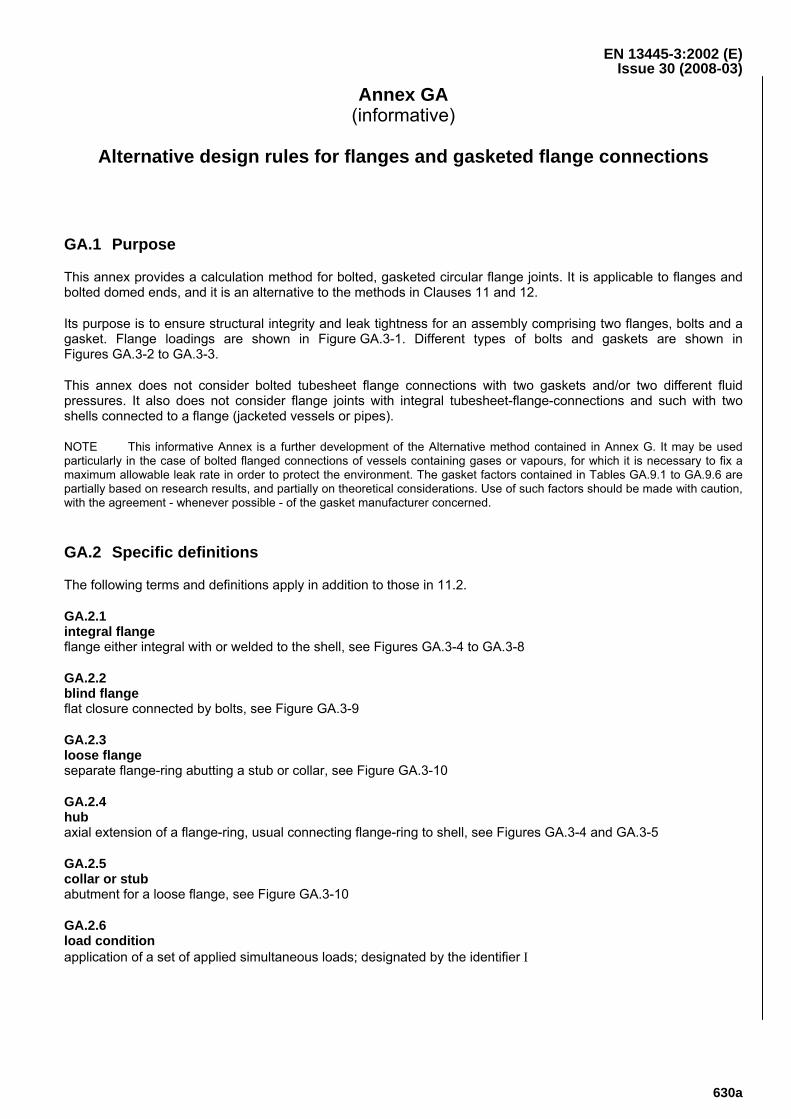
Annex GA (informative)
Alternative design rules for flanges and gasketed flange connections
GA.1 Purpose
This annex provides a calculation method for bolted, gasketed circular flange joints. It is applicable to flanges and bolted domed ends, and it is an alternative to the methods in Clauses 11 and 12.
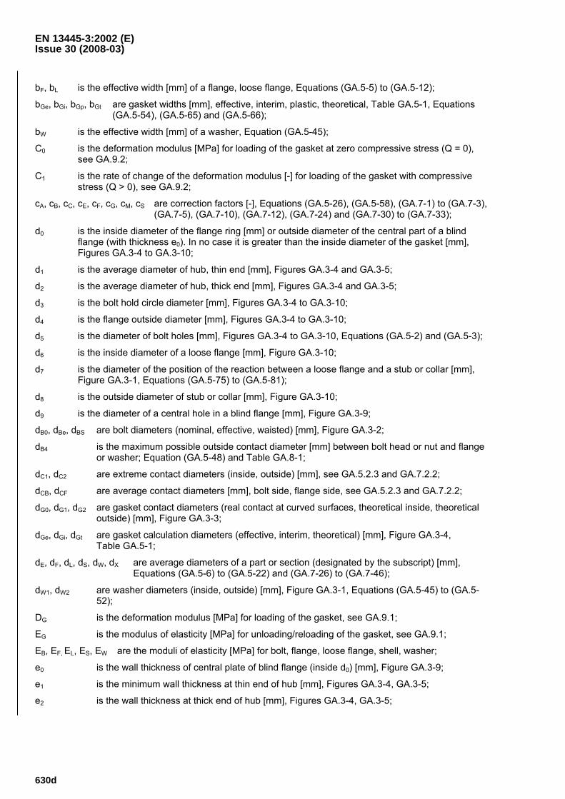
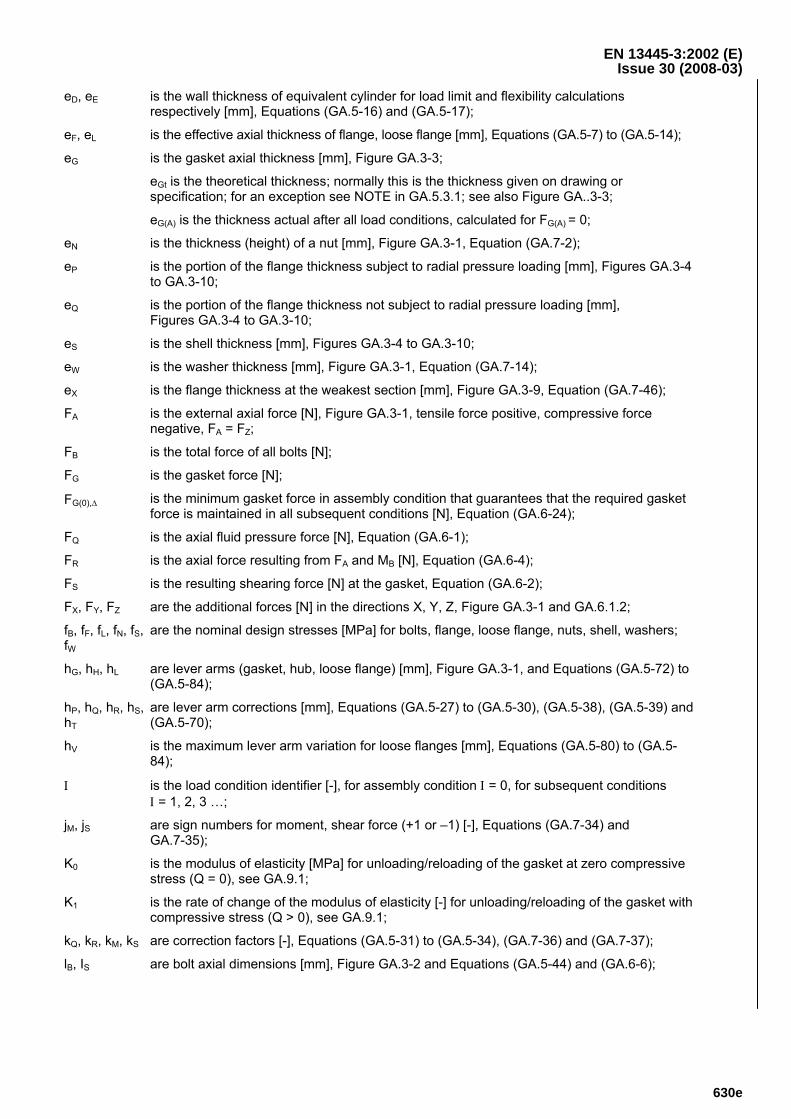
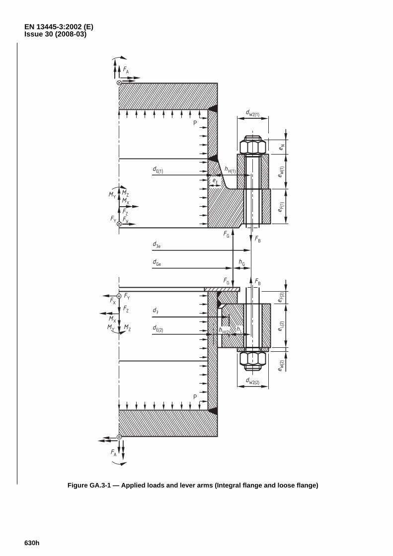
Its purpose is to ensure structural integrity and leak tightness for an assembly comprising two flanges, bolts and a gasket. Flange loadings are shown in Figure GA.3-1. Different types of bolts and gaskets are shown in Figures GA.3-2 to GA.3-3.
This annex does not consider bolted tubesheet flange connections with two gaskets and/or two different fluid pressures. It also does not consider flange joints with integral tubesheet-flange-connections and such with two shells connected to a flange (jacketed vessels or pipes).
NOTE This informative Annex is a further development of the Alternative method contained in Annex G. It may be used particularly in the case of bolted flanged connections of vessels containing gases or vapours, for which it is necessary to fix a maximum allowable leak rate in order to protect the environment. The gasket factors contained in Tables GA.9.1 to GA.9.6 are partially based on research results, and partially on theoretical considerations. Use of such factors should be made with caution, with the agreement - whenever possible - of the gasket manufacturer concerned.
GA.2 Specific definitions
The following terms and definitions apply in addition to those in 11.2.
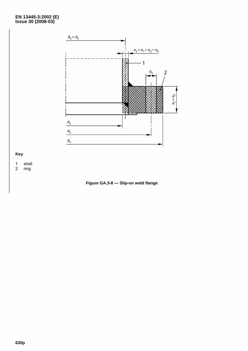
GA.2.1 integral flange flange either integral with or welded to the shell, see Figures GA.3-4 to GA.3-8
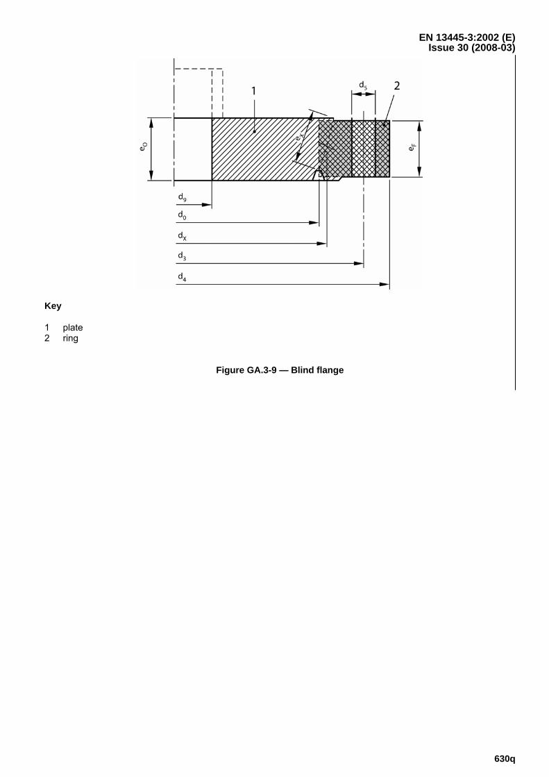
GA.2.2 blind flange flat closure connected by bolts, see Figure GA.3-9
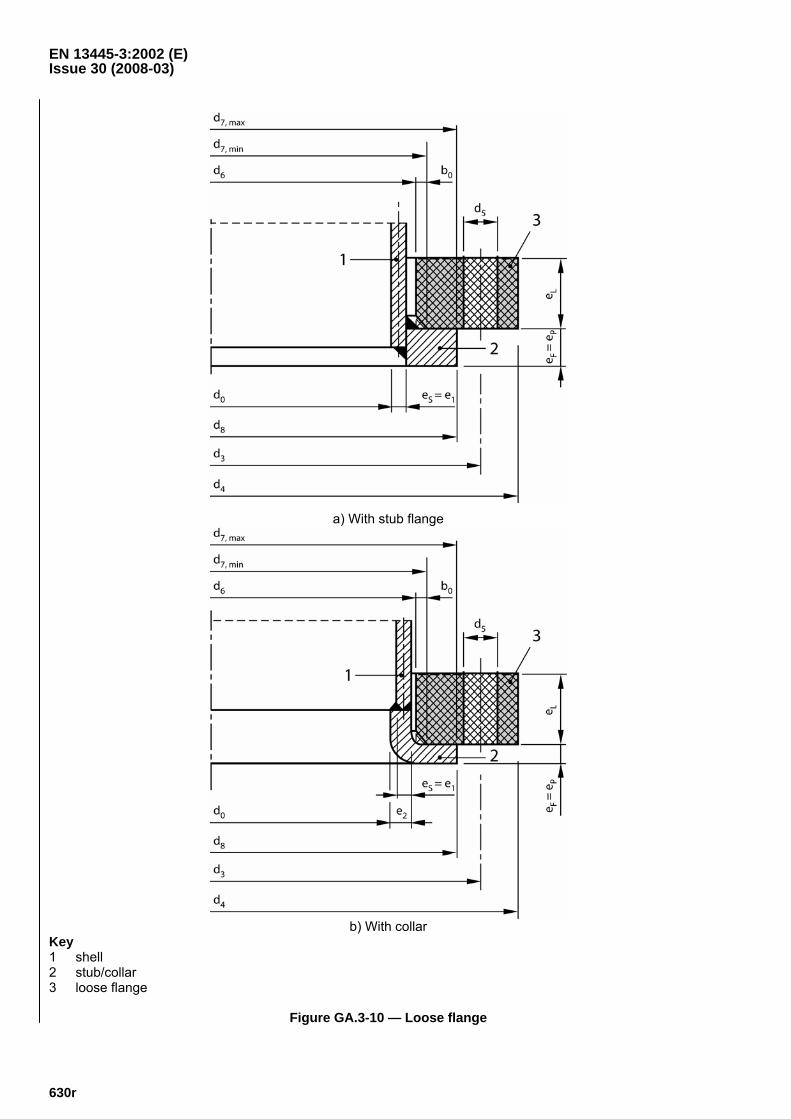
GA.2.3 loose flange separate flange-ring abutting a stub or collar, see Figure GA.3-10
GA.2.4 hub axial extension of a flange-ring, usual connecting flange-ring to shell, see Figures GA.3-4 and GA.3-5
GA.2.5 collar or stub abutment for a loose flange, see Figure GA.3-10
GA.2.6 load condition application of a set of applied simultaneous loads; designated by the identifier Ι
EN 13445-3:2002 (E) Issue 30 (2008-03)
630b
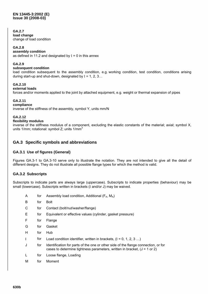
GA.2.7 load change change of load condition
GA.2.8 assembly condition as defined in 11.2 and designated by Ι = 0 in this annex
GA.2.9 subsequent condition load condition subsequent to the assembly condition, e.g. working condition, test condition, conditions arising during start-up and shut-down, designated by Ι = 1, 2, 3…
GA.2.10 external loads forces and/or moments applied to the joint by attached equipment, e.g. weight or thermal expansion of pipes
GA.2.11 compliance inverse of the stiffness of the assembly, symbol Y, units mm/N
GA.2.12 flexibility modulus inverse of the stiffness modulus of a component, excluding the elastic constants of the material; axial; symbol X, units 1/mm; rotational: symbol Z; units 1/mm3
GA.3 Specific symbols and abbreviations
GA.3.1 Use of figures (General)
Figures GA.3-1 to GA.3-10 serve only to illustrate the notation. They are not intended to give all the detail of different designs. They do not illustrate all possible flange types for which the method is valid.
GA.3.2 Subscripts
Subscripts to indicate parts are always large (uppercase). Subscripts to indicate properties (behaviour) may be small (lowercase). Subscripts written in brackets (Ι and/or J) may be waived.
A for Assembly load condition, Additional (FA, MA)
B for Bolt
C for Contact (bolt/nut/washer/flange)
E for Equivalent or effective values (cylinder, gasket pressure)
F for Flange
G for Gasket
H for Hub
Ι for Load condition identifier, written in brackets, (Ι = 0, 1, 2, 3 …)
J for Identification for parts of the one or other side of the flange connection, or for cases to determine tightness parameters, written in bracket, (J = 1 or 2)
L for Loose flange, Loading
M for Moment
EN 13445-3:2002 (E) Issue 30 (2008-03)
630c
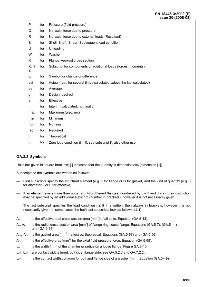
P for Pressure (fluid pressure)
Q for Net axial force due to pressure
R for Net axial force due to external loads (Resultant)
S for Shell, Shaft, Shear, Subsequent load condition
U for Unloading
W for Washer
X for Flange weakest cross section
X, Y, Z
for Subscript for components of additional loads (forces, moments)
Δ for Symbol for change or difference
act for Actual (real, for several times calculated values the last calculated)
av for Average
d for Design, desired
e for Effective
i for Interim (calculated, not finally)
max for Maximum (also: mx)
min for Minimum
nom for Nominal
req for Required
t for Theoretical
0 for Zero load condition (Ι = 0, see subscript Ι), also other use
GA.3.3 Symbols
Units are given in square brackets; [-] indicates that the quantity is dimensionless (dimension [1]).
Subscripts to the symbols are written as follows:
⎯ First subscripts specify the structural element (e.g. F for flange or G for gasket) and the kind of quantity (e.g. 3 for diameter 3 or E for effective).
⎯ If an element exists more than once (e.g. two different flanges, numbered by J = 1 and J = 2), their distinction may be specified by an additional subscript (number in brackets); however it is not necessarily given.
⎯ The last subscript specifies the load condition (Ι). If it is written, then always in brackets; however it is not necessarily given. In some cases the both last subscripts look as follows: (J, Ι).
AB is the effective total cross-section area [mm2] of all bolts, Equation (GA.5-43);
AF, AL is the radial cross-section area [mm2] of flange ring, loose flange, Equations (GA.5-7), (GA.5-11) and (GA.5-14);
AGe, AGt is the gasket area [mm2], effective, theoretical, Equations (GA.5-67) and (GA.5-56);
AQ is the effective area [mm2] for the axial fluid-pressure force, Equation (GA.5-69);
b0 is the width [mm] of the chamfer or radius on a loose flange, Figure GA.3-10;
bCB, bCF are contact widths [mm], bolt side, flange side, see GA.5.2.3 and GA.7.2.2;
bCC is the contact width common for bolt and flange side of a washer [mm], Equation (GA.5-49);
EN 13445-3:2002 (E) Issue 30 (2008-03)
630d
bF, bL is the effective width [mm] of a flange, loose flange, Equations (GA.5-5) to (GA.5-12);
bGe, bGi, bGp, bGt are gasket widths [mm], effective, interim, plastic, theoretical, Table GA.5-1, Equations (GA.5-54), (GA.5-65) and (GA.5-66);
bW is the effective width [mm] of a washer, Equation (GA.5-45);
C0 is the deformation modulus [MPa] for loading of the gasket at zero compressive stress (Q = 0), see GA.9.2;
C1 is the rate of change of the deformation modulus [-] for loading of the gasket with compressive stress (Q > 0), see GA.9.2;
cA, cB, cC, cE, cF, cG, cM, cS are correction factors [-], Equations (GA.5-26), (GA.5-58), (GA.7-1) to (GA.7-3), (GA.7-5), (GA.7-10), (GA.7-12), (GA.7-24) and (GA.7-30) to (GA.7-33);
d0 is the inside diameter of the flange ring [mm] or outside diameter of the central part of a blind flange (with thickness e0). In no case it is greater than the inside diameter of the gasket [mm], Figures GA.3-4 to GA.3-10;
d1 is the average diameter of hub, thin end [mm], Figures GA.3-4 and GA.3-5;
d2 is the average diameter of hub, thick end [mm], Figures GA.3-4 and GA.3-5;
d3 is the bolt hold circle diameter [mm], Figures GA.3-4 to GA.3-10;
d4 is the flange outside diameter [mm], Figures GA.3-4 to GA.3-10;
d5 is the diameter of bolt holes [mm], Figures GA.3-4 to GA.3-10, Equations (GA.5-2) and (GA.5-3);
d6 is the inside diameter of a loose flange [mm], Figure GA.3-10;
d7 is the diameter of the position of the reaction between a loose flange and a stub or collar [mm], Figure GA.3-1, Equations (GA.5-75) to (GA.5-81);
d8 is the outside diameter of stub or collar [mm], Figure GA.3-10;
d9 is the diameter of a central hole in a blind flange [mm], Figure GA.3-9;
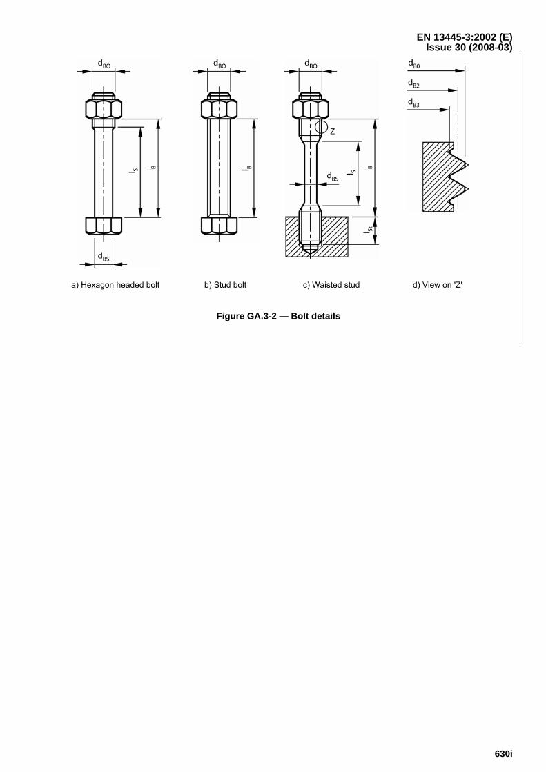
dB0, dBe, dBS are bolt diameters (nominal, effective, waisted) [mm], Figure GA.3-2;
dB4 is the maximum possible outside contact diameter [mm] between bolt head or nut and flange or washer; Equation (GA.5-48) and Table GA.8-1;
dC1, dC2 are extreme contact diameters (inside, outside) [mm], see GA.5.2.3 and GA.7.2.2;
dCB, dCF are average contact diameters [mm], bolt side, flange side, see GA.5.2.3 and GA.7.2.2;
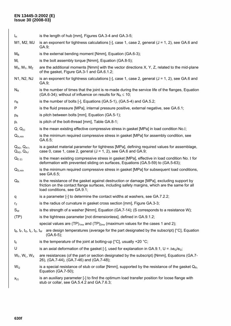
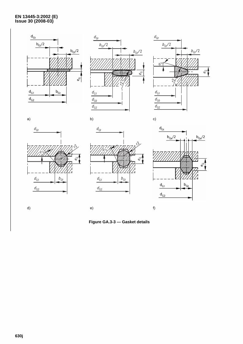
dG0, dG1, dG2 are gasket contact diameters (real contact at curved surfaces, theoretical inside, theoretical outside) [mm], Figure GA.3-3;
dGe, dGi, dGt are gasket calculation diameters (effective, interim, theoretical) [mm], Figure GA.3-4, Table GA.5-1;
dE, dF, dL, dS, dW, dX are average diameters of a part or section (designated by the subscript) [mm], Equations (GA.5-6) to (GA.5-22) and (GA.7-26) to (GA.7-46);
dW1, dW2 are washer diameters (inside, outside) [mm], Figure GA.3-1, Equations (GA.5-45) to (GA.5-52);
DG is the deformation modulus [MPa] for loading of the gasket, see GA.9.1;
EG is the modulus of elasticity [MPa] for unloading/reloading of the gasket, see GA.9.1;
EB, EF, EL, ES, EW are the moduli of elasticity [MPa] for bolt, flange, loose flange, shell, washer;
e0 is the wall thickness of central plate of blind flange (inside d0) [mm], Figure GA.3-9;
e1 is the minimum wall thickness at thin end of hub [mm], Figures GA.3-4, GA.3-5;
e2 is the wall thickness at thick end of hub [mm], Figures GA.3-4, GA.3-5;
EN 13445-3:2002 (E) Issue 30 (2008-03)
630e
eD, eE is the wall thickness of equivalent cylinder for load limit and flexibility calculations respectively [mm], Equations (GA.5-16) and (GA.5-17);
eF, eL is the effective axial thickness of flange, loose flange [mm], Equations (GA.5-7) to (GA.5-14);
eG is the gasket axial thickness [mm], Figure GA.3-3;
eGt is the theoretical thickness; normally this is the thickness given on drawing or specification; for an exception see NOTE in GA.5.3.1; see also Figure GA..3-3;
eG(A) is the thickness actual after all load conditions, calculated for FG(A) = 0;
eN is the thickness (height) of a nut [mm], Figure GA.3-1, Equation (GA.7-2);
eP is the portion of the flange thickness subject to radial pressure loading [mm], Figures GA.3-4 to GA.3-10;
eQ is the portion of the flange thickness not subject to radial pressure loading [mm], Figures GA.3-4 to GA.3-10;
eS is the shell thickness [mm], Figures GA.3-4 to GA.3-10;
eW is the washer thickness [mm], Figure GA.3-1, Equation (GA.7-14);
eX is the flange thickness at the weakest section [mm], Figure GA.3-9, Equation (GA.7-46);
FA is the external axial force [N], Figure GA.3-1, tensile force positive, compressive force negative, FA = FZ;
FB is the total force of all bolts [N];
FG is the gasket force [N];
FG(0),Δ is the minimum gasket force in assembly condition that guarantees that the required gasket force is maintained in all subsequent conditions [N], Equation (GA.6-24);
FQ is the axial fluid pressure force [N], Equation (GA.6-1);
FR is the axial force resulting from FA and MB [N], Equation (GA.6-4);
FS is the resulting shearing force [N] at the gasket, Equation (GA.6-2);
FX, FY, FZ are the additional forces [N] in the directions X, Y, Z, Figure GA.3-1 and GA.6.1.2;
fB, fF, fL, fN, fS, fW
are the nominal design stresses [MPa] for bolts, flange, loose flange, nuts, shell, washers;
hG, hH, hL are lever arms (gasket, hub, loose flange) [mm], Figure GA.3-1, and Equations (GA.5-72) to (GA.5-84);
hP, hQ, hR, hS, hT
are lever arm corrections [mm], Equations (GA.5-27) to (GA.5-30), (GA.5-38), (GA.5-39) and (GA.5-70);
hV is the maximum lever arm variation for loose flanges [mm], Equations (GA.5-80) to (GA.5-84);
Ι is the load condition identifier [-], for assembly condition Ι = 0, for subsequent conditions Ι = 1, 2, 3 …;
jM, jS are sign numbers for moment, shear force (+1 or –1) [-], Equations (GA.7-34) and GA.7-35);
K0 is the modulus of elasticity [MPa] for unloading/reloading of the gasket at zero compressive stress (Q = 0), see GA.9.1;
K1 is the rate of change of the modulus of elasticity [-] for unloading/reloading of the gasket with compressive stress (Q > 0), see GA.9.1;
kQ, kR, kM, kS are correction factors [-], Equations (GA.5-31) to (GA.5-34), (GA.7-36) and (GA.7-37);
lB, IS are bolt axial dimensions [mm], Figure GA.3-2 and Equations (GA.5-44) and (GA.6-6);
EN 13445-3:2002 (E) Issue 30 (2008-03)
630f
lH is the length of hub [mm], Figures GA.3-4 and GA.3-5;
M1, M2, MJ is an exponent for tightness calculations [-], case 1, case 2, general (J = 1, 2), see GA.6 and GA.9;
MB is the external bending moment [Nmm], Equation (GA.6-3);
Mt is the bolt assembly torque [Nmm], Equation (GA.8-5);
MX, MY, MZ are the additional moments [Nmm] with the vector directions X, Y, Z, related to the mid-plane of the gasket, Figure GA.3-1 and GA.6.1.2;
N1, N2, NJ is an exponent for tightness calculations [-], case 1, case 2, general (J = 1, 2), see GA.6 and GA.9;
NR is the number of times that the joint is re-made during the service life of the flanges, Equation (GA.6-34); without of influence on results for NR ≤ 10;
nB is the number of bolts [-], Equations (GA.5-1), (GA.5-4) and GA.5.2;
P is the fluid pressure [MPa], internal pressure positive, external negative, see GA.6.1;
pB is pitch between bolts [mm], Equation (GA.5-1);
pt is pitch of the bolt-thread [mm], Table GA.8-1;
Q, Q(Ι) is the mean existing effective compressive stress in gasket [MPa] in load condition No.Ι;
QA,min is the minimum required compressive stress in gasket [MPa] for assembly condition, see GA.6.5;
QA0, QA1, QA2, QAJ
is a gasket material parameter for tightness [MPa], defining required values for assemblage, case 0, case 1, case 2, general (J = 1, 2), see GA.6 and GA.9;
QE (Ι) is the mean existing compressive stress in gasket [MPa], effective in load condition No. Ι for deformation with prevented sliding on surfaces, Equations (GA.5-59) to (GA.5-63);
QS,min is the minimum required compressive stress in gasket [MPa] for subsequent load conditions, see GA.6.5;
QR is the resistance of the gasket against destruction or damage [MPa], excluding support by friction on the contact flange surfaces, including safety margins, which are the same for all load conditions, see GA.9.1;
q is a parameter [-] to determine the contact widths at washers, see GA.7.2.2;
r2 is the radius of curvature in gasket cross section [mm], Figure GA.3-3;
SW is the strength of a washer [Nmm], Equation (GA.7-14); (S corresponds to a resistance W);
(TP) is the tightness parameter [not dimensionless], defined in GA.9.1.2;
special values are (TP)1mx and (TP)2mx (maximum values for the cases 1 and 2);
tB, tF, tG, tL, tS, tW are design temperatures (average for the part designated by the subscript) [°C], Equation (GA.6-5);
t0 is the temperature of the joint at bolting-up [°C], usually +20 °C;
U is an axial deformation of the gasket [-], used for explanation in GA.9.1, U = ΔeG/eG;
WF, WL, WX are resistances (of the part or section designated by the subscript) [Nmm], Equations (GA.7-26), (GA.7-44), (GA.7-46) and (GA.7-48);
WQ is a special resistance of stub or collar [Nmm], supported by the resistance of the gasket QR, Equation (GA.7-50);
x(Ι) is an auxiliary parameter [-] to find the optimum load transfer position for loose flange with stub or collar, see GA.5.4.2 and GA.7.6.3;
EN 13445-3:2002 (E) Issue 30 (2008-03)
630g
XB, XG,XW are axial flexibility moduli of bolts, gasket, washer [1/mm], Equations (GA.5-44), (GA.5-53) and (GA.5-68);
YB, YG, YQ, YR are axial compliances of the joint [mm/N] corresponding to loads FB, FG, FQ, FR, Equations (GA.6-8) to (GA.6-11);
ZF, ZL are rotational flexibility moduli of flange, loose flange [1/mm3], Equations (GA.5-35), (GA.5-36) and (GA.5-40) to (GA.5-42);
αB, αF, αG, αL, αW are average thermal expansion coefficients [K-1], averaged between t0 and tB, tF, tG, tL, tW;
β, γ, δ, ϑ , κ, λ
are intermediate working variables [-], Equations (GA.5-15), (GA.5-23) to (GA.5-25), (GA.5-79), (GA.7-28) and (GA.7-29);
ΔeG(0) is the change of the gasket thickness [mm] during bolt tightening in assemblage (up to the end of the load condition No. 0), Equation (GA.5-63);
ΔeG(Ι) is the change of the gasket thickness [mm] after assemblage up to the end of load condition No. Ι, Equation (GA.5-63);
ΔUT(Ι) is the overall axial thermal deformation [mm] relative to assemblage in load condition No. Ι, Equation (GA.6-5);
ΔUG(Ι) is the overall axial elastic and thermal deformation [mm] at the gasket relative to assemblage in load condition No. Ι, Equation (GA.6-12);
εn+, εn-, ε1+, ε1- are the scatter values of the initial bolt load [-] for nB bolts and 1 bolt, above and below the nominal value respectively, see GA.8.2;
ΘF, ΘL is the rotation of flange, loose flange, due to an applied moment [-],Equations (GA.8-7) and (GA.8-8);
μB, μG is the coefficient of friction at the bolts, at the gasket [-], see GA.8, GA.9;
ρ is a diameter ratio for blind flanges [-], Equation (GA.5-37);
ΦB, ΦC, ΦF, ΦG, ΦL, ΦW, ΦX
are load ratios (of the part or section designated by the subscript) [-], Equations (GA.7-1), (GA.7-4), (GA.7-7) to (GA.7-9), (GA.7-23), (GA.7-25) and (GA.7-43) to (GA.7-49);
ϕG is the angle of inclination of a sealing face [rad or deg], Figure GA.3-3, Table GA.5-1;
ϕS is the angle of inclination of the connected shell [rad or deg], Figures GA.3-6, GA.3-7, with sign convention;
Ψ is the load ratio of flange ring due to radial force [-], Equation (GA.7-38);
ΨZ is the particular value of Ψ[-], Table GA.7-1.
EN 13445-3:2002 (E) Issue 30 (2008-03)
630h
P
FA
FX
FZFY
MYMX
MZ
dE(1) hH(1)
dW2(1)
e Ne W
(1)
e F(1)
FBd3e
dGe
P
FA
FG
FG
hG
FB
hLhH(2)dE(2)
d7
dW2(2)
e L(2)
e F(2)
e W(2
)
FXFZ
FY
MY
MXMZ
eE
Figure GA.3-1 — Applied loads and lever arms (Integral flange and loose flange)
EN 13445-3:2002 (E) Issue 30 (2008-03)
630i
a) Hexagon headed bolt b) Stud bolt c) Waisted stud d) View on 'Z'
Figure GA.3-2 — Bolt details
EN 13445-3:2002 (E) Issue 30 (2008-03)
630j
dGt
bGt/2
bGt/2
dG1
dG2
e G
dG0
r2
dGt
bGt/2
bGt/2
dG1
dG2
e G
dG0
Gϕ
r2
a) b) c)
dGt
bGtdG1
dG2
e G
r2
Gϕ
dGt
bGtdG1
dG2
r2
Gϕ
e G
d) e) f)
Figure GA.3-3 — Gasket details
EN 13445-3:2002 (E) Issue 30 (2008-03)
630k
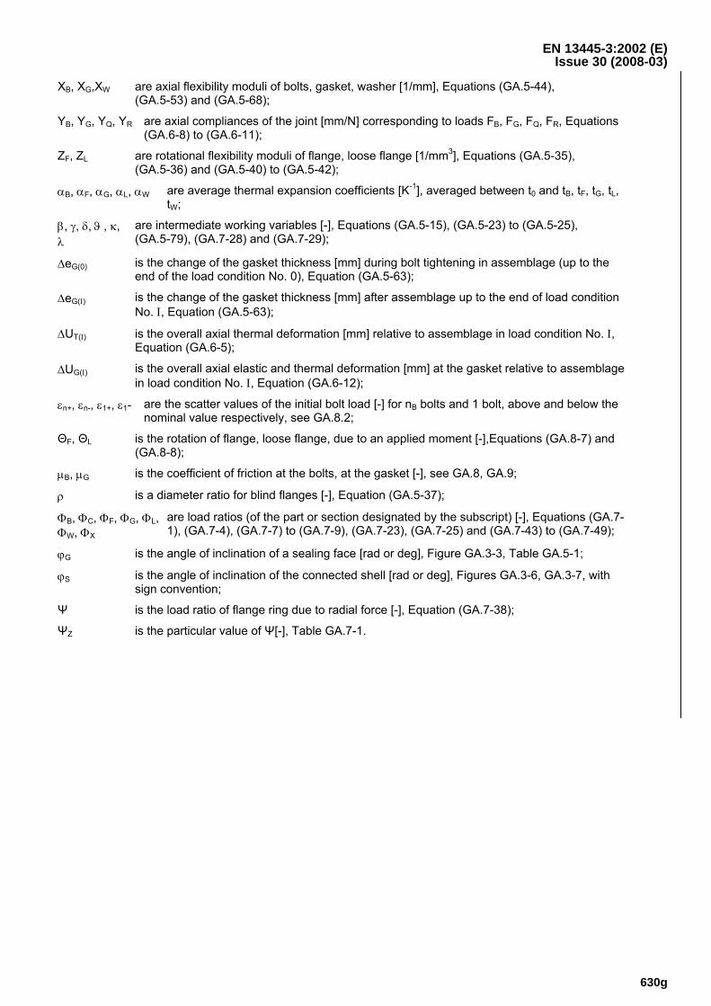
a) Tapered hub with no thickening in the bore
b) Tapered hub with thickening in the bore
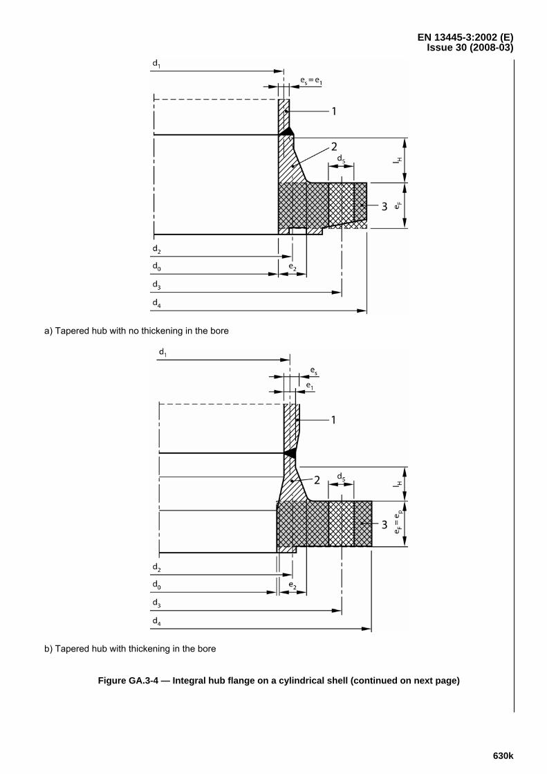
Figure GA.3-4 — Integral hub flange on a cylindrical shell (continued on next page)
EN 13445-3:2002 (E) Issue 30 (2008-03)
630l
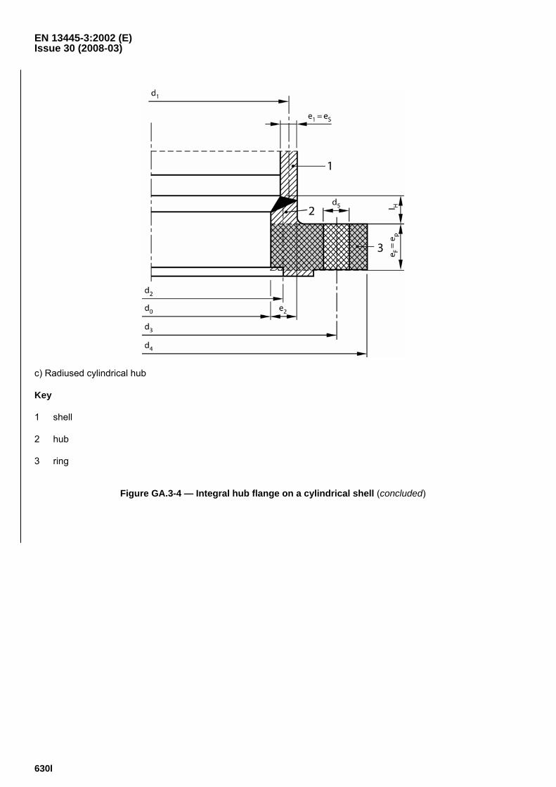
c) Radiused cylindrical hub
Key
1 shell
2 hub
3 ring
Figure GA.3-4 — Integral hub flange on a cylindrical shell (concluded)
EN 13445-3:2002 (E) Issue 30 (2008-03)
630m
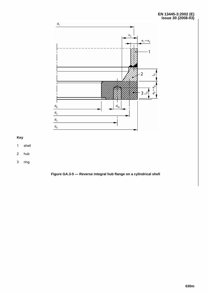
Key
1 shell
2 hub
3 ring
Figure GA.3-5 — Reverse integral hub flange on a cylindrical shell
EN 13445-3:2002 (E) Issue 30 (2008-03)
630n
dS = dE
d0
d3
d4
1
2d5t
e F
e P e Q
l 5t
eS
- Sϕ
a) Flange at the small end of the cone
dS = dE
d0
d3
d4
1 2
d5
e S
+ Sϕ
e F =
e P
b) Flange at the large end of the cone
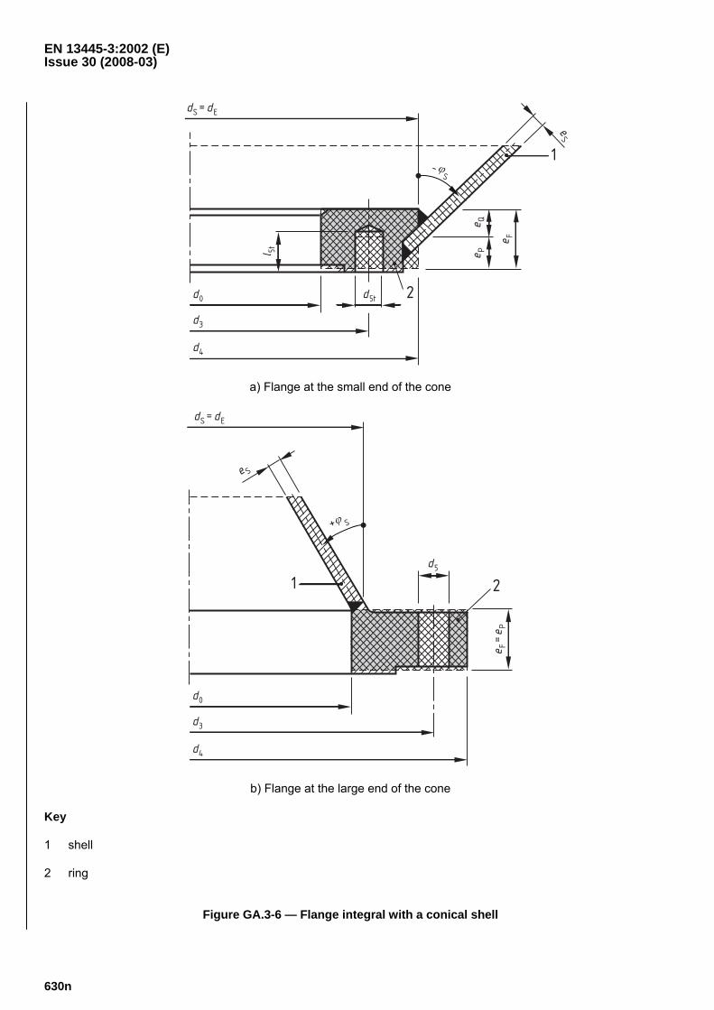
Key
1 shell
2 ring
Figure GA.3-6 — Flange integral with a conical shell
EN 13445-3:2002 (E) Issue 30 (2008-03)
630o
dS = dE
d0
d3
d4
1 2 d5
+ Sϕ
e S
r K e F
e P e Q
a) Domed cover
dS = dE
d0
d3
d4
1
2d5t
- Sϕ
rK
eS
e F =
e P
l 5t
b) Insert pad
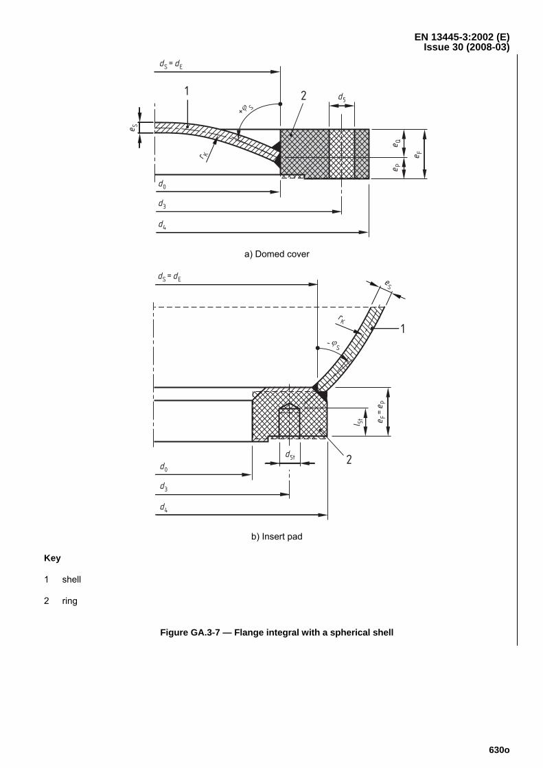
Key
1 shell
2 ring
Figure GA.3-7 — Flange integral with a spherical shell
EN 13445-3:2002 (E) Issue 30 (2008-03)
630p
Key
1 shell 2 ring
Figure GA.3-8 — Slip-on weld flange
EN 13445-3:2002 (E) Issue 30 (2008-03)
630q
Key
1 plate 2 ring
Figure GA.3-9 — Blind flange
EN 13445-3:2002 (E) Issue 30 (2008-03)
630r
a) With stub flange
b) With collar
Key 1 shell 2 stub/collar 3 loose flange
Figure GA.3-10 — Loose flange
EN 13445-3:2002 (E) Issue 30 (2008-03)
630s
GA.4 General
GA.4.1 Conditions of applicability
GA.4.1.1 Geometry
The method applies when:
⎯ whole assembly is (in essential) axisymmetric;
⎯ there are two similar or dissimilar flanges, or one flange and a blind flange;
⎯ there are four or more identical, uniformly distributed bolts;
⎯ there may be washers on one side or on both sides of the connection;
⎯ there is a circular gasket, located within the bolt circle on smooth surfaces and compressed axially;
⎯ flange dimensions meet the following conditions:
0,2 ≤ bF/eF ≤ 5,0; 0,2 ≤ bL/eL ≤ 5,0; (GA.4-1)
cosϕS ≥ 1/{1 + 0,01 · dS/eS} (GA.4-2)
NOTE Condition (GA.4-1) need not be met for a collar in combination with a loose flange.
The following configurations are excluded from the scope of the method:
⎯ flanges of essentially non-axisymmetric geometry, e.g. split loose flanges, oval flanges or gusset reinforced flanges;
⎯ flange joints having metal to metal contact between the flanges or between the flanges and a spacer ring fitted either inside or outside the gasket or inside or outside the bolts. An example is a spiral wound gasket on a high pressure application.
GA.4.1.2 Material characteristics
Values of nominal design stress for bolts (GA.7) shall be determined as for shells in clause 6. This is valid also for nuts and washers.
Material properties for gaskets may be taken from GA.9.
GA.4.1.3 Loads
The method applies to the following loads:
⎯ fluid pressure: internal or external;
⎯ external loads: axial force and bending moment, torsional moment and shear force also;
⎯ thermal expansion of flanges, bolts, washers and gasket.
GA.4.2 Mechanical model
The method is based on the following mechanical model:
⎯ The geometry of both flanges and gasket is axisymmetric. Small deviations such as those due to a finite number of bolts are permitted.
EN 13445-3:2002 (E) Issue 30 (2008-03)
630t
⎯ Flange ring cross section remains undeformed. Only circumferential stresses and strains in the ring are considered. Radial and axial stresses in the ring are neglected. This leads to the condition (GA.4-1).
⎯ The hub at the flange ring is treated as a conical shell with linear variable wall thickness. Material and temperature are the same as for the flange ring.
⎯ The shell connected to the flange may be cylindrical, conical or spherical, always with constant wall thickness. Membrane forces are calculated for the true shape; effects of bending and shear are calculated for a cylindrical shell; for conical and spherical shells an equivalent cylindrical shell is used. This leads to the condition (GA.4-2).
⎯ The gasket is in contact with the flange faces over an annular area which the method determined. The effective radial width bGe of the gasket, which may be less than its true width, is calculated for the assembly condition (Ι = 0) and assumed to be unchanged for all subsequent load conditions (Ι = 1, 2 …). The calculation of bGe includes elastic rotations of both flanges, and approximate elastic and plastic deformations of gasket.
⎯ Deformation of the gasket is different for loading and unloading/reloading:
For loading (increasing compressive gasket stress Q, actual Q) a deformation modulus DG = C0 + C1 · Q is used which includes all possible deformations (elastic and plastic, creep also).
For unloading (decreasing Q) and reloading (again increasing Q) an elastic modulus EG = K0 + K1 · Qmax is used which includes only elastic deformations and creep and depends on the prior reached maximum Qmax.
⎯ Thermal and mechanical deformations of flanges, shells, bolts, washers and gasket are taken into account.
⎯ Deformations of the whole flange connection are calculated axisymmetric. An external bending moment is treated as an equivalent axial force transmitted by the bolts; see GA.6.1. Deformations due to shear forces and torsional moment are neglected.
⎯ Load changes between load conditions cause changes in the bolt and gasket forces. These are calculated taking account the elastic deformations of all components. For the gasket also irreversible deformations are considered. The required initial assembly force is calculated (see GA.6) to ensure sufficient high gasket forces in all load conditions (to ensure leak tightness).
⎯ Load limit checks are based on limit loads of each component. Excessive plastic deformations are prevented. The load limit for gaskets, which depends on QR, is an approximation. Torsional moment and shear force are respected only with their influence on the load limit of the gasket; their influences on load limits of shell and flange are ignored.
The following are not taken into account in the model:
⎯ Bolt bending stiffness and bending strength. Ignoring bolt bending is a conservative simplification. Calculated tensile stiffness of bolts includes deformation of the bolt threads within a nut or tapped hole, see Equation (GA.5-44).
⎯ Creep of flanges and bolts. This is due to lack of relevant material data for creep deformation.
⎯ Different radial deformation of the flanges. Within two equal flanges this is not relevant as the radial deformations are equal.
EN 13445-3:2002 (E) Issue 30 (2008-03)
630u
GA.4.3 Calculation method
GA.4.3.1 Required checks
⎯ The assembly bolt loads shall be sufficiently large to ensure the leak tightness requirements for all subsequent load conditions. Additionally it is recommended to specify the procedure of assemblage with the required parameters (e.g. torque); see GA.6.
⎯ The load ratios for bolts and gasket and for both flanges are to be checked for all load conditions (assembly condition included); see GA.7.
GA.4.3.2 Load cases to be calculated
⎯ Minimum required are calculations for the assembly condition; the main working condition and the initial test condition. (If the test shall not be repeated at any time, the calculations may be separated into two sets: A: Working plus assemblage; B: Test plus assemblage. The stronger of both assemblages is valid.)
⎯ If more than one regular working condition exists, all these conditions are to be calculated together with the main working condition. (Example: Cleaning of a vessel with steam; temperature higher and fluid pressure lower than in the main working condition.)
⎯ If in an exceptional condition leakage shall be prevented, this condition is to be calculated together with the main working condition; however in this case a lower safety is acceptable, e.g. as for test condition. Such an exceptional condition may be not only one with increased fluid pressure but also one with rapid changes of temperatures during start-up or shut-down. There may be several such exceptional conditions.
GA.4.3.3 Working with the method
⎯ The calculations shall be made in the corroded condition (corrosion allowances are subtracted).
⎯ The numbering of load conditions is arbitrary; assemblage always shall be designated by Ι = 0.
⎯ The calculations shall be made as much as possible independent on the entire different load cases (see GA.5). For several calculations the initial gasket load FG(Ι=0) shall be known, while the subsequent load cases (Ι > 1) are without influence (see also GA.5).
⎯ It is recommended to calculate all load conditions together, using tables or lists or matrices, e.g. for each load condition one column.
GA.5 Parameters
GA.5.0 General
All the following parameters are independent on all subsequent load conditions. A few parameters depend on the initial gasket force after bolting up.
GA.5.1 Flange parameters
GA.5.1.0 General
If both flanges of the flange connection are different they may be designated by an additional subscript J (J = 1, 2), written in brackets. If both flanges are of the same type and have equal dimensions the following parameters need to calculate only once (otherwise twice).
NOTE The flange dimensions are shown in Figures GA.3-4 to GA.3-10.
EN 13445-3:2002 (E) Issue 30 (2008-03)
630v
Specific flange types are treated as follows:
An integral flange is calculated as an equivalent ring with rectangular cross-section, with dimensions bF and eF, connected at diameter d2 to a conical hub. The conical hub with the length IH at diameter d1 is connected to a shell of constant wall thickness eS. Conical hub and flange ring are one part of the same material; the material of the shell may be different. The conical hub may be absent and the flange ring is direct connected to the shell (d2 = d1, IH = 0).
A blind flange is calculated as an equivalent ring with rectangular cross-section, with dimensions bF and eF, connected at diameter d0 to a plate of constant thickness e0. It may have a central opening of diameter d9. A possible connected nozzle at the opening is ignored in the calculation.
A loose flange is calculated as an equivalent ring with rectangular cross-section, with dimensions bL and eL, without connection to a shell. The stub or collar is treated in the same way as an integral flange.
A screwed flange is calculated as a loose flange with inside diameter equal load transmission diameter equal average thread diameter.
GA.5.1.1 Bolt holes
The pitch between bolts is given by:
pB = π · d3/nB (GA.5-1)
The effective diameter of the bolt hole is:
B555e /pddd ⋅= (GA.5-2)
With blind holes, the hole diameter is assumed to be:
d5 = d5t · l5t/eFb (GA.5-3)
The effective bolt circle diameter is:
d3e = d3 · (1 – 2/nB2) (GA.5-4)
NOTE If d3 and nB are equal for both flanges, also pB and d3e are equal for both sides; however d5 may be different (d5,1 ≠ d5,2).
GA.5.1.2 Flange ring
G.5.1.2.0 General
In Figures GA.3-4 to GA.3-10, the effective ring is indicated by chain dotted lines.
The effective thickness eF or eL is the average thickness of the flange ring. It shall be obtained by dividing the radial gross cross-section area of the ring AF or AL (bolt holes or stud holes ignored) by the radial width of this section.
NOTE Since there are a large variety of shapes of cross sections, formulae are not given for calculation of AF or AL for specific flange types.
GA.5.1.2.1 Integral flange and blank flange (see Figures GA.3-4 to GA.3-9)
bF = (d4 – d0)/2 – d5e (GA.5-5)
dF = (d4 + d0)/2 (GA.5-6)
EN 13445-3:2002 (E) Issue 30 (2008-03)
630w
eF = 2 · AF/(d4 – d0) (GA.5-7)
bL = dL = eL = 0 (GA.5-8)
GA.5.1.2.2 Loose flange with stub or collar (see Figure GA.3-10)
bF = (d8 – d0)/2 (GA.5-9)
dF = (d8 + d0)/2 = d8 + bF (GA.5-10)
eF = 2 · AF/(d8 – d0) (GA.5-11)
bL = (d4 – d6)/2 – d5e (GA.5-12)
dL = (d4 + d6)/2 (GA.5-13)
eL = 2 · AL/(d4 – d6) (GA.5-14)
GA.5.1.3 Conical hub and connected shell
GA.5.1.3.1 If the flange has a conical (tapered) hub (integral with the flange ring and of the same material), then the following parameters shall be calculated:
β = e2/e1 (GA.5-15)
( )( ) ( ) ( ) ⎪⎭
⎪⎬⎫
⎪⎩
⎪⎨⎧
+⋅
⋅−+=
⋅
⋅4 4
H2
114
H1D
Iedβ/3
I1β1ee (GA.5-16)
( )( ) ⎪⎭
⎪⎬⎫
⎪⎩
⎪⎨⎧
+⋅
⋅−+⋅=
⋅ H11
H1E
Iedβ/3I1β
1ee (GA.5-17)
dE = {min (d1 – e1 + eE; d2 + e2 – eE) + max (d1 + e1 – eE; d2 – e2 + eE)}/2 (GA.5-18)
GA.5.1.3.2 If the flange has no hub, then the following is to be assumed:
eE = eS (GA.5-19)
dE = dS (GA.5-20)
GA.5.1.3.3 For a blind flange (no connected shell) is to be assumed:
eE = 0 (GA.5-21)
dE = d0 (GA.5-22)
NOTE Equations (GA.5-21), (GA.5-22) apply whether the blind flange has an opening (with or without nozzle) or not.
GA.5.1.4 Flexibility-related flange parameters
NOTE When the gasket is of flat type, the parameter hQ below can be calculated only when dGe has been determined, i.e. when the calculations in GA.5.3.2 has been performed.
GA.5.1.4.1 Integral flange, stub or collar
SEF
FE
cosdb
de
ϕ⋅⋅=γ
⋅ (GA.5-23)
EN 13445-3:2002 (E) Issue 30 (2008-03)
630x
F
EE
eed
cos0,550⋅
⋅ϕ⋅=ϑ S (GA.5-24)
FQFp /ee/ee1 =−=λ (GA.5-25)
( ) ( ) 423 ϑ⋅γ⋅+ ϑ⋅6+ϑ⋅λ⋅−⋅+λ⋅+λ⋅−⋅⋅ϑ⋅γ+
ϑ⋅γ+=
⎥⎦⎤
⎢⎣⎡ 221633141
1c
2F (GA.5-26)
ϑ⋅γ+
ϑ+λ⋅−⋅⋅⋅=
121
de
e1,100hE
EFS (GA.5-27)
ϑ⋅γ+ϑ⋅γ−λ⋅−
= ⋅121eh
2
FT (GA.5-28)
( ){ } ( )2GeES
2EPFTQSQ /ddtan0,5/ded2hkhh ⋅ϕ⋅−⋅⋅⋅+⋅= (GA.5-29)
STRSR tan0,5hkhh ϕ⋅⋅−⋅= (GA.5-30)
For conical and cylindrical shells:
kQ = +0,85/cosϕS (GA.5-31)
kR = -0,15/cosϕS (GA.5-32)
For a spherical shell:
kQ = +0,35/cosϕS (GA.5-33)
kR = -0,65/cosϕS (GA.5-34)
For all cases:
3FF
FFF
ebπcd3Z
⋅⋅
⋅⋅= (GA.5-35)
ZL = 0 (GA.5-36)
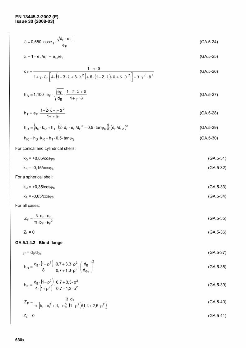
GA.5.1.4.2 Blind flange
ρ = d9/dGe (GA.5-37)
( ) 2
Ge
E2
22E
Q dd
ρ1,30,7ρ3,30,7
8ρ1dh ⎟⎟
⎠
⎞⎜⎜⎝
⎛⋅
⋅+⋅+
⋅−⋅
= (GA.5-38)
( )( ) 2
2
2
2E
R ρ1,30,7ρ3,30,7
ρ14ρ1dh
⋅+
⋅+⋅
+⋅
−⋅= (GA.5-39)
( ) ( )[ ]2230F
3FF
FF
ρ2,61,4/ρ1edebπd3
Z⋅+−⋅⋅+⋅⋅
⋅= (GA.5-40)
ZL = 0 (GA.5-41)
EN 13445-3:2002 (E) Issue 30 (2008-03)
630y
GA.5.1.4.3 Loose flange with stub or collar
For the stub or collar Equations (GA.5-23) to (GA.5-35) shall be used.
For the loose flange itself the following is valid:
3LL
LL ebπ
d3Z
⋅⋅
⋅= (GA.5-42)
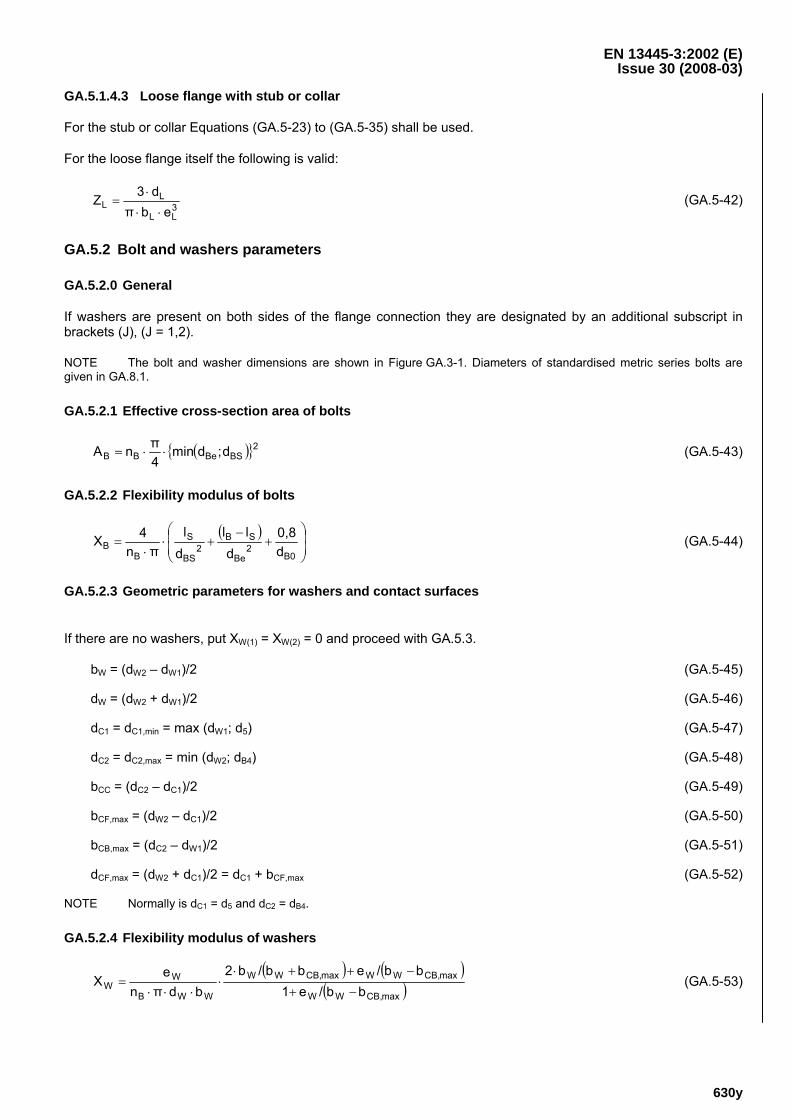
GA.5.2 Bolt and washers parameters
GA.5.2.0 General
If washers are present on both sides of the flange connection they are designated by an additional subscript in brackets (J), (J = 1,2).
NOTE The bolt and washer dimensions are shown in Figure GA.3-1. Diameters of standardised metric series bolts are given in GA.8.1.
GA.5.2.1 Effective cross-section area of bolts
( ){ }2BSBeBB d;dmin
4πnA ⋅⋅= (GA.5-43)
GA.5.2.2 Flexibility modulus of bolts
( )⎟⎟⎠
⎞⎜⎜⎝
⎛+
−+⋅
⋅=
B02
Be
SB2
BS
S
BB d
0,8d
lld
lπn
4X (GA.5-44)
GA.5.2.3 Geometric parameters for washers and contact surfaces
If there are no washers, put XW(1) = XW(2) = 0 and proceed with GA.5.3.
bW = (dW2 – dW1)/2 (GA.5-45)
dW = (dW2 + dW1)/2 (GA.5-46)
dC1 = dC1,min = max (dW1; d5) (GA.5-47)
dC2 = dC2,max = min (dW2; dB4) (GA.5-48)
bCC = (dC2 – dC1)/2 (GA.5-49)
bCF,max = (dW2 – dC1)/2 (GA.5-50)
bCB,max = (dC2 – dW1)/2 (GA.5-51)
dCF,max = (dW2 + dC1)/2 = dC1 + bCF,max (GA.5-52)
NOTE Normally is dC1 = d5 and dC2 = dB4.
GA.5.2.4 Flexibility modulus of washers
( ) ( )( )maxCB,WW
maxCB,WWmaxCB,WW
WWB
WW bb/e1
bb/ebb/b2bdπn
eX
−+
−++⋅⋅
⋅⋅⋅= (GA.5-53)
EN 13445-3:2002 (E) Issue 30 (2008-03)
630z
NOTE XW includes an estimated correction factor for different axial stresses in different sections.
GA.5.3 Gasket parameters
G.5.3.0 General for gasket
NOTE Various types of gaskets and their dimensions are shown in Figure GA.3-3. The selection of type and material of the gasket may depend on the tolerated leakage rate. Some information to the gasket behaviour and non-mandatory values for material properties are given in GA.9.
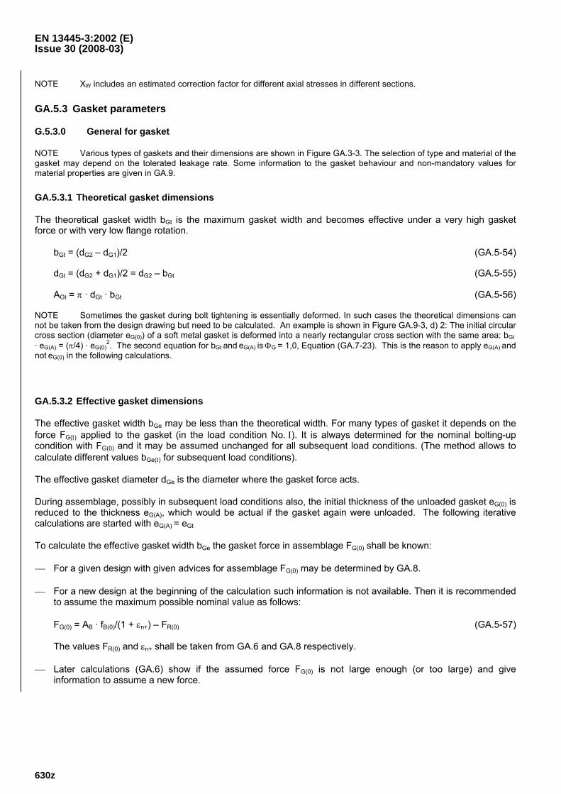
GA.5.3.1 Theoretical gasket dimensions
The theoretical gasket width bGt is the maximum gasket width and becomes effective under a very high gasket force or with very low flange rotation.
bGt = (dG2 – dG1)/2 (GA.5-54)
dGt = (dG2 + dG1)/2 = dG2 – bGt (GA.5-55)
AGt = π · dGt · bGt (GA.5-56)
NOTE Sometimes the gasket during bolt tightening is essentially deformed. In such cases the theoretical dimensions can not be taken from the design drawing but need to be calculated. An example is shown in Figure GA.9-3, d) 2: The initial circular cross section (diameter eG(0)) of a soft metal gasket is deformed into a nearly rectangular cross section with the same area: bGt · eG(A) = (π/4) · eG(0)
2. The second equation for bGt and eG(A) is ΦG = 1,0, Equation (GA.7-23). This is the reason to apply eG(A) and not eG(0) in the following calculations.
GA.5.3.2 Effective gasket dimensions
The effective gasket width bGe may be less than the theoretical width. For many types of gasket it depends on the force FG(Ι) applied to the gasket (in the load condition No. Ι). It is always determined for the nominal bolting-up condition with FG(0) and it may be assumed unchanged for all subsequent load conditions. (The method allows to calculate different values bGe(Ι) for subsequent load conditions).
The effective gasket diameter dGe is the diameter where the gasket force acts.
During assemblage, possibly in subsequent load conditions also, the initial thickness of the unloaded gasket eG(0) is reduced to the thickness eG(A), which would be actual if the gasket again were unloaded. The following iterative calculations are started with eG(A) = eGt
To calculate the effective gasket width bGe the gasket force in assemblage FG(0) shall be known:
⎯ For a given design with given advices for assemblage FG(0) may be determined by GA.8.
⎯ For a new design at the beginning of the calculation such information is not available. Then it is recommended to assume the maximum possible nominal value as follows:
FG(0) = AB · fB(0)/(1 + εn+) – FR(0) (GA.5-57)
The values FR(0) and εn+ shall be taken from GA.6 and GA.8 respectively.
⎯ Later calculations (GA.6) show if the assumed force FG(0) is not large enough (or too large) and give information to assume a new force.
EN 13445-3:2002 (E) Issue 30 (2008-03)
630aa
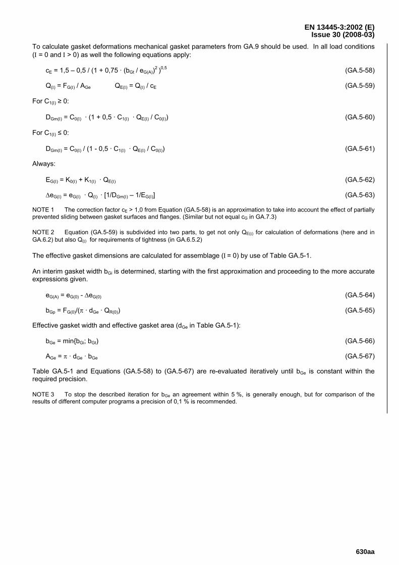
To calculate gasket deformations mechanical gasket parameters from GA.9 should be used. In all load conditions (Ι = 0 and Ι > 0) as well the following equations apply:
cE = 1,5 – 0,5 / (1 + 0,75 · (bGt / eG(A))2 )0,5 (GA.5-58)
Q(Ι) = FG(Ι) / AGe QE(Ι) = Q(Ι) / cE (GA.5-59)
For C1(Ι) ≥ 0:
DGm(Ι) = C0(Ι) · (1 + 0,5 · C1(Ι) · QE(Ι) / C0(Ι)) (GA.5-60)
For C1(Ι) ≤ 0:
DGm(Ι) = C0(Ι) / (1 - 0,5 · C1(Ι) · QE(Ι) / C0(Ι)) (GA.5-61)
Always:
EG(Ι) = K0(Ι) + K1(Ι) · QE(Ι) (GA.5-62)
ΔeG(Ι) = eG(Ι) · Q(Ι) · [1/DGm(Ι) – 1/EG(Ι)] (GA.5-63)
NOTE 1 The correction factor cE > 1,0 from Equation (GA.5-58) is an approximation to take into account the effect of partially prevented sliding between gasket surfaces and flanges. (Similar but not equal cG in GA.7.3)
NOTE 2 Equation (GA.5-59) is subdivided into two parts, to get not only QE(Ι) for calculation of deformations (here and in GA.6.2) but also Q(Ι) for requirements of tightness (in GA.6.5.2)
The effective gasket dimensions are calculated for assemblage (Ι = 0) by use of Table GA.5-1.
An interim gasket width bGi is determined, starting with the first approximation and proceeding to the more accurate expressions given.
eG(A) = eG(0) - ΔeG(0) (GA.5-64)
bGp = FG(0)/(π · dGe · QR(0)) (GA.5-65)
Effective gasket width and effective gasket area (dGe in Table GA.5-1):
bGe = min{bGi; bGt) (GA.5-66)
AGe = π · dGe · bGe (GA.5-67)
Table GA.5-1 and Equations (GA.5-58) to (GA.5-67) are re-evaluated iteratively until bGe is constant within the required precision.
NOTE 3 To stop the described iteration for bGe an agreement within 5 %, is generally enough, but for comparison of the results of different computer programs a precision of 0,1 % is recommended.
EN 13445-3:2002 (E) Issue 30 (2008-03)
630ab
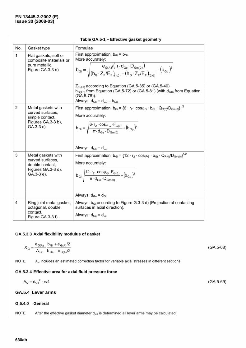
Table GA.5-1 – Effective gasket geometry
No. Gasket type Formulae First approximation: bGi = bGt More accurately:
( ) ( )( )( )( ) ( )( )
( )2Gp
2,0FFG1,0FFG
0GmGeAGGi b
/EZh/EZhDdπ/e
b +⋅+⋅
⋅⋅=
ZF(J,0) according to Equation (GA.5-35) or (GA.5-40) hG(J,0) from Equation (GA.5-72) or (GA.5-81) (with d7(0) from Equation (GA.5-78)).
1 Flat gaskets, soft or composite materials or pure metallic, Figure GA.3-3 a)
Always: dGe = dG2 – bGe
First approximation: bGi = {6 · r2 · cosϕG · bGt · QR(0)/DGm(0)}1/2
More accurately:
( )2Gp
Gm(0)Ge
G(0)G2Gi b
DdπFcosr6
b +⋅⋅
⋅ϕ⋅⋅=
2 Metal gaskets with curved surfaces, simple contact, Figures GA.3-3 b), GA.3-3 c).
Always: dGe = dG0
First approximation: bGi = {12 · r2 · cosϕG · bGt · QR(0)/DGm(0)}1/2
More accurately:
( ) ( )2GpGm(0)Ge
0GG2Gi b
DdπFcosr12
b +⋅⋅
⋅ϕ⋅⋅
3 Metal gaskets with curved surfaces, double contact, Figures GA.3-3 d), GA.3-3 e).
Always: dGe = dGt
Always: bGi according to Figure G.3-3 d) (Projection of contacting surfaces in axial direction).
4 Ring joint metal gasket, octagonal, double contact, Figure GA.3-3 f). Always: dGe = dGt
GA.5.3.3 Axial flexibility modulus of gasket
/2eb/2eb
Ae
XG(A)Ge
G(A)Gt
Gt
G(A)G +
+⋅= (GA.5-68)
NOTE XG includes an estimated correction factor for variable axial stresses in different sections.
GA.5.3.4 Effective area for axial fluid pressure force
AQ = dGe2 · π/4 (GA.5-69)
GA.5.4 Lever arms
G.5.4.0 General
NOTE After the effective gasket diameter dGe is determined all lever arms may be calculated.
EN 13445-3:2002 (E) Issue 30 (2008-03)
630ac
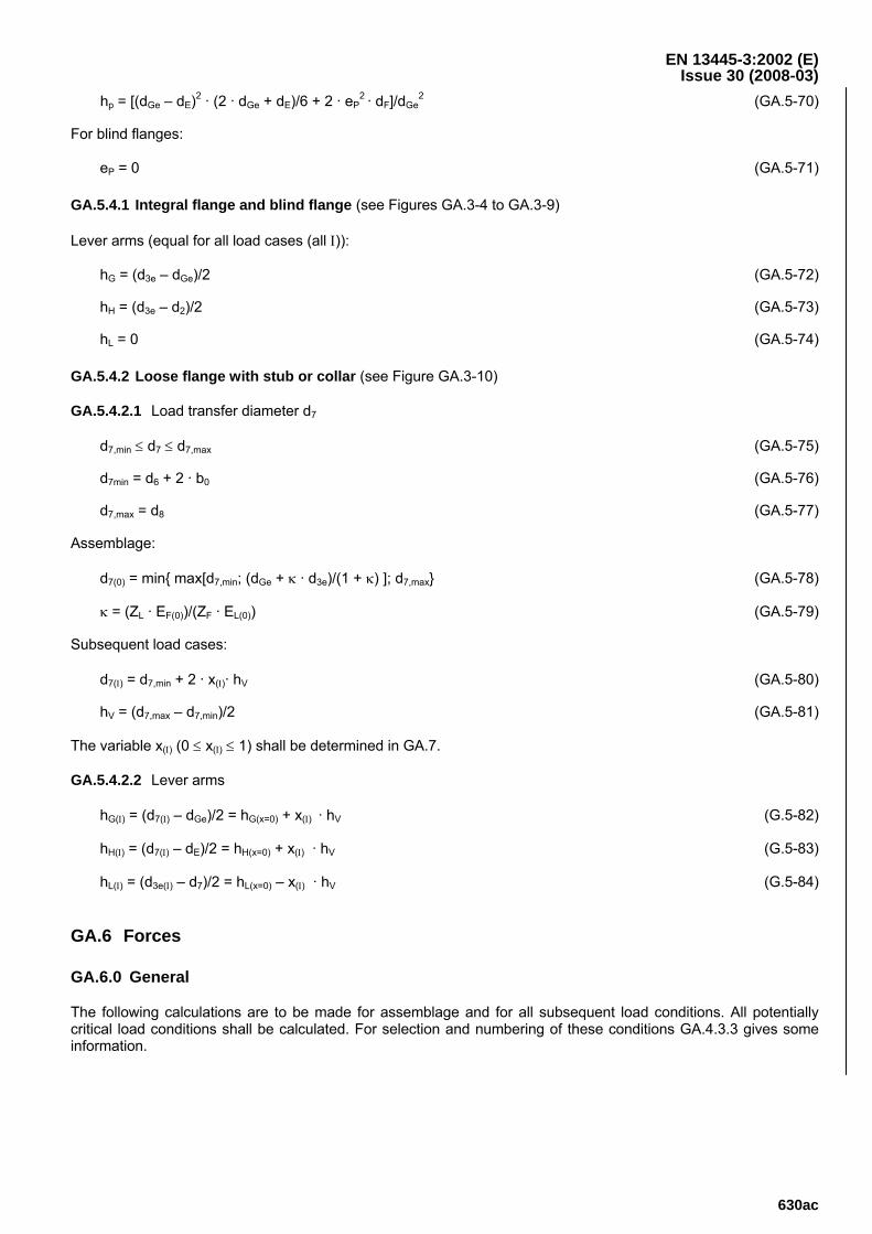
hp = [(dGe – dE)2 · (2 · dGe + dE)/6 + 2 · eP2 · dF]/dGe
2 (GA.5-70)
For blind flanges:
eP = 0 (GA.5-71)
GA.5.4.1 Integral flange and blind flange (see Figures GA.3-4 to GA.3-9)
Lever arms (equal for all load cases (all Ι)):
hG = (d3e – dGe)/2 (GA.5-72)
hH = (d3e – d2)/2 (GA.5-73)
hL = 0 (GA.5-74)
GA.5.4.2 Loose flange with stub or collar (see Figure GA.3-10)
GA.5.4.2.1 Load transfer diameter d7
d7,min ≤ d7 ≤ d7,max (GA.5-75)
d7min = d6 + 2 · b0 (GA.5-76)
d7,max = d8 (GA.5-77)
Assemblage:
d7(0) = min{ max[d7,min; (dGe + κ · d3e)/(1 + κ) ]; d7,max} (GA.5-78)
κ = (ZL · EF(0))/(ZF · EL(0)) (GA.5-79)
Subsequent load cases:
d7(Ι) = d7,min + 2 · x(Ι)· hV (GA.5-80)
hV = (d7,max – d7,min)/2 (GA.5-81)
The variable x(Ι) (0 ≤ x(Ι) ≤ 1) shall be determined in GA.7.
GA.5.4.2.2 Lever arms
hG(Ι) = (d7(Ι) – dGe)/2 = hG(x=0) + x(Ι) · hV (G.5-82)
hH(Ι) = (d7(Ι) – dE)/2 = hH(x=0) + x(Ι) · hV (G.5-83)
hL(Ι) = (d3e(Ι) – d7)/2 = hL(x=0) – x(Ι) · hV (G.5-84)
GA.6 Forces
GA.6.0 General
The following calculations are to be made for assemblage and for all subsequent load conditions. All potentially critical load conditions shall be calculated. For selection and numbering of these conditions GA.4.3.3 gives some information.
EN 13445-3:2002 (E) Issue 30 (2008-03)
630ad
GA.6.1 Loads
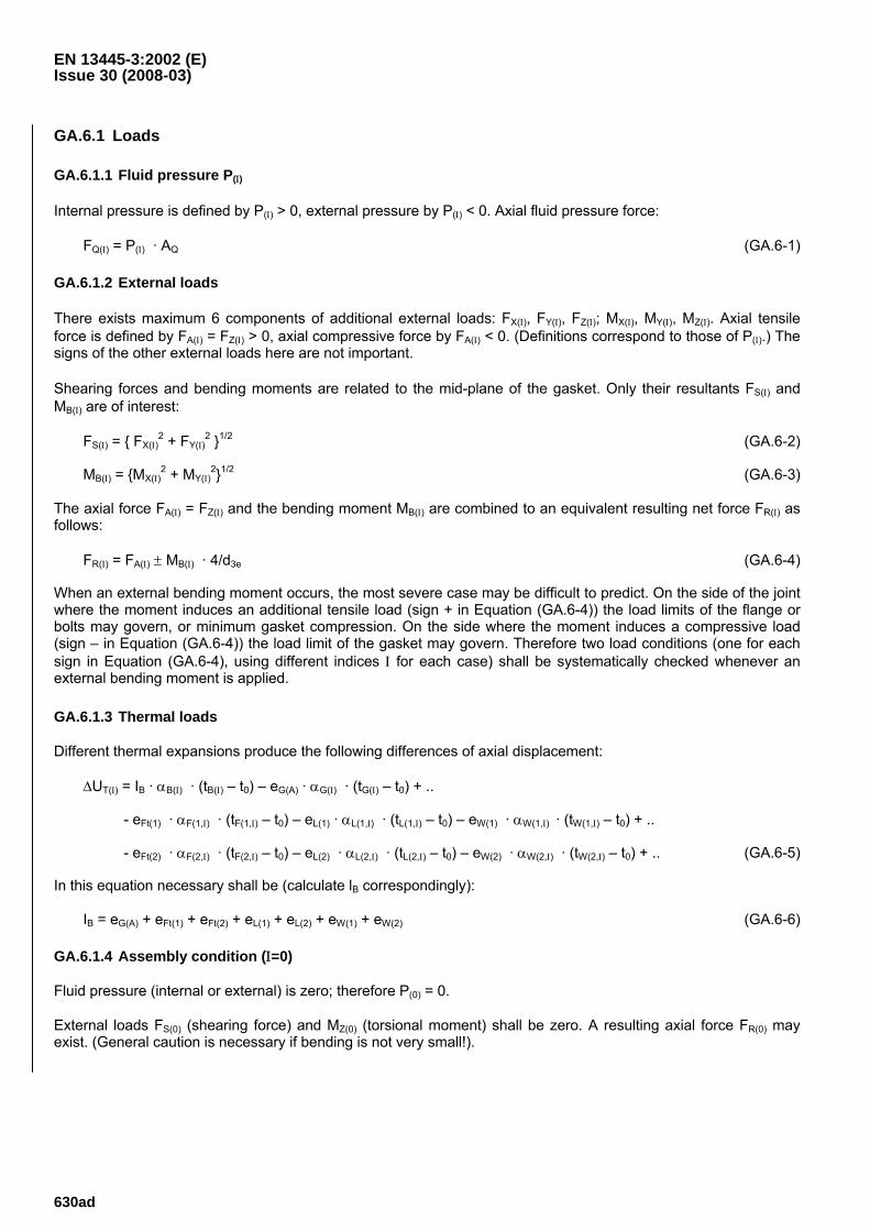
GA.6.1.1 Fluid pressure P(Ι)
Internal pressure is defined by P(Ι) > 0, external pressure by P(Ι) < 0. Axial fluid pressure force:
FQ(Ι) = P(Ι) · AQ (GA.6-1)
GA.6.1.2 External loads
There exists maximum 6 components of additional external loads: FX(Ι), FY(Ι), FZ(Ι); MX(Ι), MY(Ι), MZ(Ι). Axial tensile force is defined by FA(Ι) = FZ(Ι) > 0, axial compressive force by FA(Ι) < 0. (Definitions correspond to those of P(Ι).) The signs of the other external loads here are not important.
Shearing forces and bending moments are related to the mid-plane of the gasket. Only their resultants FS(Ι) and MB(Ι) are of interest:
FS(Ι) = { FX(Ι)2 + FY(Ι)
2 }1/2 (GA.6-2)
MB(Ι) = {MX(Ι)2 + MY(Ι)
2}1/2 (GA.6-3)
The axial force FA(Ι) = FZ(Ι) and the bending moment MB(Ι) are combined to an equivalent resulting net force FR(Ι) as follows:
FR(Ι) = FA(Ι) ± MB(Ι) · 4/d3e (GA.6-4)
When an external bending moment occurs, the most severe case may be difficult to predict. On the side of the joint where the moment induces an additional tensile load (sign + in Equation (GA.6-4)) the load limits of the flange or bolts may govern, or minimum gasket compression. On the side where the moment induces a compressive load (sign – in Equation (GA.6-4)) the load limit of the gasket may govern. Therefore two load conditions (one for each sign in Equation (GA.6-4), using different indices Ι for each case) shall be systematically checked whenever an external bending moment is applied.
GA.6.1.3 Thermal loads
Different thermal expansions produce the following differences of axial displacement:
ΔUT(Ι) = IB · αB(Ι) · (tB(Ι) – t0) – eG(A) · αG(Ι) · (tG(Ι) – t0) + ..
- eFt(1) · αF(1,Ι) · (tF(1,Ι) – t0) – eL(1) · αL(1,Ι) · (tL(1,Ι) – t0) – eW(1) · αW(1,Ι) · (tW(1,Ι) – t0) + ..
- eFt(2) · αF(2,Ι) · (tF(2,Ι) – t0) – eL(2) · αL(2,Ι) · (tL(2,Ι) – t0) – eW(2) · αW(2,Ι) · (tW(2,Ι) – t0) + .. (GA.6-5)
In this equation necessary shall be (calculate lB correspondingly):
IB = eG(A) + eFt(1) + eFt(2) + eL(1) + eL(2) + eW(1) + eW(2) (GA.6-6)
GA.6.1.4 Assembly condition (Ι=0)
Fluid pressure (internal or external) is zero; therefore P(0) = 0.
External loads FS(0) (shearing force) and MZ(0) (torsional moment) shall be zero. A resulting axial force FR(0) may exist. (General caution is necessary if bending is not very small!).
EN 13445-3:2002 (E) Issue 30 (2008-03)
630ae
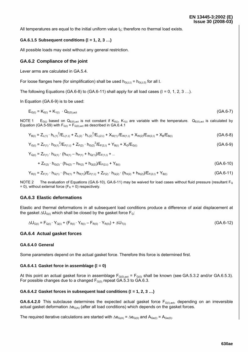
All temperatures are equal to the initial uniform value t0; therefore no thermal load exists.
GA.6.1.5 Subsequent conditions (Ι = 1, 2, 3 …)
All possible loads may exist without any general restriction.
GA.6.2 Compliance of the joint
Lever arms are calculated in GA.5.4.
For loose flanges here (for simplification) shall be used hG(J,Ι) = hG(J,0) for all Ι.
The following Equations (GA.6-8) to (GA.6-11) shall apply for all load cases (Ι = 0, 1, 2, 3 …).
In Equation (GA.6-9) is to be used:
EG(Ι) = K0(Ι) + K1(Ι) · QE(0),act (GA.6-7)
NOTE 1 EG(Ι) based on QE(0),act is not constant if K0(Ι), K1(Ι) are variable with the temperature. QE(0),act is calculated by Equation (GA.5-59) with FG(I) = FG(0),act as described in GA.6.4.1
YB(Ι) = ZL(1) · hL(1)2/EL(1,Ι) + ZL(2) · hL(2)
2/EL(2,Ι) + XW(1) /EW(1,Ι) + XW(2)/EW(2,Ι) + XB/EB(Ι) (GA.6-8)
YG(Ι) = ZF(1) · hG(1)2/EF(1,Ι) + ZF(2) · hG(2)
2/EF(2,Ι) + YB(Ι) + XG/EG(Ι) (GA.6-9)
YQ(Ι) = ZF(1) · hG(1) · (hH(1) – hP(1) + hQ(1))/EF(1,Ι) + ..
+ ZF(2) · hG(2) · (hH(2) – hP(2) + hQ(2))/EF(2,Ι) + YB(Ι) (GA.6-10)
YR(Ι) = ZF(1) · hG(1) · (hH(1) + hR(1))/EF(1,Ι) + ZF(2) · hG(2) · (hH(2) + hR(2))/EF(2,Ι) + YB(Ι) (GA.6-11)
NOTE 2 The evaluation of Equations (GA.6-10), GA.6-11) may be waived for load cases without fluid pressure (resultant FQ = 0), without external force (FR = 0) respectively.
GA.6.3 Elastic deformations
Elastic and thermal deformations in all subsequent load conditions produce a difference of axial displacement at the gasket ΔUG(Ι) which shall be closed by the gasket force FG:
ΔUG(Ι) = FQ(Ι) · YQ(Ι) + (FR(Ι) · YR(Ι) – FR(0) · YR(0)) + ΔUT(Ι) (GA.6-12)
GA.6.4 Actual gasket forces
GA.6.4.0 General
Some parameters depend on the actual gasket force. Therefore this force is determined first.
GA.6.4.1 Gasket force in assemblage (Ι = 0)
At this point an actual gasket force in assemblage FG(0),act = FG(0) shall be known (see GA.5.3.2 and/or GA.6.5.3). For possible changes due to a changed FG(0) repeat GA.5.3 to GA.6.3.
GA.6.4.2 Gasket forces in subsequent load conditions (Ι = 1, 2, 3 …)
GA.6.4.2.0 This subclause determines the expected actual gasket force FG(Ι),act, depending on an irreversible actual gasket deformation ΔeG(A) (after all load conditions) which depends on the gasket forces.
The required iterative calculations are started with ΔeG(A) = ΔeG(0) and AGe(Ι) = AGe(0).
EN 13445-3:2002 (E) Issue 30 (2008-03)
630af
GA.6.4.2.1 Calculate the expected actual gasket forces in all subsequent conditions FG(Ι),act:
FG(Ι),act = {FG(0),act · YG(0) + ΔeG(0) − ΔeG(A) − ΔUG(Ι) }/YG(Ι) (GA.6-13)
GA.6.4.2.2 For increased precision calculate effective gasket areas AGe(Ι) possibly different for all load conditions. For narrow gaskets the initial assumption AGe(Ι) = AGe(0) may be remained.
GA.6.4.2.3 Calculate the actual effective gasket pressure QE(Ι) and the corresponding irreversible gasket deformation ΔeG(Ι) by use of Equations (GA.5-58) to (GA.5-63), and the then actual gasket thickness eG(A) as follows:
ΔeG(A) = max(all Ι ≥ 0){ΔeG(Ι) }(all Ι) (GA.6-14)
eG(A) = eGt − ΔeG(A) (GA.6-15)
G.6.4.2.4 If ΔeG(A) has been increased, return to GA.6.4.2.1; otherwise the iteration is stopped.
GA.6.5 Required gasket force
GA.6.5.0 General
The required gasket forces depend on the tightness behaviour. Corresponding explanations and required parameters are given in GA.9. Deviating tightness calculations are permitted.
According to GA.9 for gas fluid a required or desired tightness parameter (TP) shall be assumed:
(TP) = 100 for very low tightness requirements (GA.6-16a)
(TP) = 102 for low tightness requirements (GA.6-16b)
(TP) = 104 for median (normal) tightness requirements (GA.6-16c)
(TP) = 106 for high tightness requirements (GA.6-16d)
(TP) = 108 for very high tightness requirements (GA.6-16e)
For liquid fluid and for load conditions without fluid pressure this parameter is not required and may be put equal zero.
GA.6.5.1 Assembly condition (Ι=0)
The minimum gasket force in assemblage FG(0),min, required for later tightness, depends on type, dimensions and material of the gasket; it may depend on the flange surfaces, the kind of fluid, the fluid pressure and the admissible leak rate in it subsequent load conditions; it is given by:
FG(0),min = AGe · QA,min (GA.6-17)
For liquid fluid:
QA,min = QA0 (GA.6-18)
For gas fluid:
QA,min = min {QA1 · (TP)1/M1; QA2 · (TP)1/M2} (GA.6-19)
(TP) = max(all Ι > 0) { (TP)(Ι) } (GA.6-20)
If in GA.9 values for QA2, M2, N2 are not given, they are not to be used. If (TP) from Equation (GA.6-20) is greater than the maximum of the values (TP)1mx , (TP)2mx, given in GA.9, then the gasket probably is not appropriate for the given case.
EN 13445-3:2002 (E) Issue 30 (2008-03)
630ag
NOTE The given requirements should be fulfilled in the load condition with the highest gasket pressure Q, which normally is the assembly condition. However there may exist subsequent load conditions with gasket pressures higher than in assemblage, e.g. due to external pressure or due to temperature effects. If such a load condition occurs in a time before the tightness relevant critical load condition, in the calculation of forces it may be used instead of the assembly condition.
GA.6.5.2 Subsequent conditions (Ι = 1, 2, 3 …)
The minimum gasket force in each subsequent load condition FG(Ι),min, required for actual tightness (first term) and no loss of contact at bolts and nuts (second term), is given by:
FG(Ι),min = max { AGe · QS(Ι),min; - (FQ(Ι) + FR(Ι)) } (GA.6-21)
For liquid fluid:
QS(Ι),min = ⏐P(Ι)⏐ (GA.6-22)
For gas fluid:
QS(Ι),min = max {⏐ P(Ι) ⏐; QAJMJ/NJ
· Q(0),act1−MJ/NJ
· (TP)(Ι)1/NJ} (GA.6-23)
Q(0),act is calculated by Equation (GA.5-59) with FG(i) = FG(O), act as described in GA.6.4.1.
For QAJ, MJ, NJ see the explanations given in GA.9.1.2 after Equation (GA.9-13).
GA.6.5.3 Required gasket force in assemblage
To guarantee that the gasket force in all subsequent load conditions never falls below the required values FG(Ι),min, the gasket force in assemblage shall be at least equal to the following:
FG(0),Δ = max(all Ι > 0) {FG(I),min · YG(Ι) − ΔeG(0) + ΔeG(A) + ΔUG(Ι)}/YG(0) (GA.6-24)
Taking into account also the tightness requirement from assemblage it follows:
FG(0),req = max { FG(0),min ; FG(0),Δ } (GA.6-25)
If the actual gasket force in assemblage is less that the required:
FG(0),act < FG(0),req (GA.6-26)
then the actual force shall be increased and the calculation from GA.5.3.2 to GA.6.5.3 is to be repeated.
If the actual gasket force in assemblage is greater than the required:
FG(0),act > FG(0),req (GA.6-27)
then it is acceptable because it is conservative.
GA.6.5.4 Optimum gasket force in assemblage
The optimum (minimum required) gasket force in assemblage may be found through a number of iterations repeating the calculation from GA.6.4.1 to GA.6.5.3 until within the required precision is:
FG(0),act ≈ FG(0),req (GA.6-28)
NOTE To stop the described iteration for FG(0) an agreement within 5 % is generally enough, but for comparison of the results of different computer programs a precision of 0,1 % is recommended.
EN 13445-3:2002 (E) Issue 30 (2008-03)
630ah
GA.6.6 Forces in assembly condition (Ι = 0)
GA.6.6.0 General
The procedure of assemblage with the final bolt-tightening shall produce the bolt loads and gasket forces required for a full functional flange connection.
GA.6.6.1 Required forces
The required gasket force in assemblage FG(0),req is defined in GA.6.5.3.
The required bolt load in assemblage is the following:
FB(0),req = FG(0),req + FR(0) (GA.6-29)
GA.6.6.2 Accounting for bolt-load scatter at assembly
GA.6.6.2.0 General
All bolt-tightening methods involve some degree of inaccuracy. A possibility to take into account is described in GA.8.2, where also the required values are given.
GA.6.6.2.1 Nominal bolt assembly force, used to define the bolting up parameters
The required nominal bolt force is:
FB(0),nom ≥ FB(0),req/(1 − εn−) (GA.6-30)
For assemblage (and for advices for assemblage, e.g. required torque) it is recommended to select slightly increased forces (e.g. 5 % to 10 % above the calculated nominal), tending to better leak tightness.
For assemblage without control of the bolt load the nominal bolt load FB(0),nom is assumed equal to the average bolt load FB(0),av that can be expected in practice, independently of FB(0),req; see GA.8.2.
The following condition shall be met, where εn- shall be based on ε1- = 0,5:
FB(0),nom = FB(0),av ≥ FB(0),req/(1 − εn−) (GA.6-31)
If this is not met, the bolt tightening method initially chosen is not valid and shall be changed.
GA.6.6.2.2 Forces to be used for the load limit calculation in assemblage condition (see GA.7).
FB(0) = FB(0),max = FB(0),nom · (1 + εn+) (GA.6-32)
FG(0) = FG(0),max = FB(0),max – FR(0) (GA.6-33)
The effective gasket width bGe need not be recalculated.
GA.6.7 Forces in subsequent conditions (Ι = 1, 2, 3 …)
The calculation forces in subsequent load conditions shall be based on a design assembly gasket force FG(0),d given by:
FG(0),d = max {FG(0),Δ; FB(0),max · (2/3) · (1 – 10/NR) – FR(0) } (GA.6-34)
The corresponding subsequent gasket force and bolt load for load limit calculations are:
FG(Ι) = {FG(0),d · YG(0) + ΔeG(0) − ΔeG(A) - ΔUG(Ι)} / YG(Ι) (GA.6-35)
FB(Ι) = FG(Ι) + (FQ(Ι) + FR(Ι)) (GA.6-36)
EN 13445-3:2002 (E) Issue 30 (2008-03)
630ai
NOTE 1 To prevent leakage, the gasket force in all subsequent load conditions is recommended to be at least FG(Ι),min from Equation (GA.6-21). This corresponds to a gasket assembly force FG(0),Δ from Equation (GA.6-24). To avoid progressive distortion due to frequent re-assembly, in some cases the desired gasket assembly force FG(0),d from Equation (GA.6-34) should be higher than FG(0),Δ.
NOTE 2 When progressive distortion does not control, i.e. when FG(0),d = FG(0),Δ in Equation (GA.6-34), then the forces FG(Ι) and FB(Ι), defined by Equations (GA.6-35) and (GA.6-36), are those that exist in any condition Ι ≠ 0 for an initial bolt load equal to the minimum required FB(0),req. In GA.7, the admissibility of these minimum required forces is checked (in contrast, for assembly condition the admissibility of the maximum possible forces is checked). Actual forces in subsequent conditions are above the forces defined by Equations (GA.6-35) and (GA.6-36) due to the scatter of bolting-up method. Nevertheless it is valid to waive the amount of FB(0),act in excess of FB(0),req, since this is a "passive" ("secondary") force, which dissipates through plastic deformation.
NOTE 3 When progressive distortion controls, the maximum possible initial bolt load FB(0),max is used for determination of a fictitious gasket force (second term in Equation (GA.6-34)). Then a bolt load FB(0) > FG(0),Δ + FR(0) is applied and some plastic deformation may occur in subsequent load conditions. The calculation of load limits in GA.7 prevents global plastic deformation in all load conditions and serves to limit the accumulation of plastic deformation at each re-assembly to an acceptable limit.
GA.7 Load limits
GA.7.0 General
Loads on the system shall be within safe limits. These limits are expressed in calculated load ratios. Each load ratio shall be less or equal to unity for all load conditions.
Φ(Ι) ≤ 1,0 (Ι = 0, 1, 2, 3 …) (GA.7-0)
The index (Ι) for the load condition is omitted in the following for brevity.
The nominal design stress in the assembly condition is the same as in the test condition.
NOTE It is reminded that for assembly condition (Ι = 0) the forces to be considered are the maximum possible forces (see GA.6.6).
GA.7.1 Bolts
The load ratio of bolts shall be calculated and limited as follows:
( ) 1,0μc3,21fcA
FΦ 2BA
BBB
BB ≤⋅⋅+⋅
⋅⋅= (GA.7-1)
The nominal design stress fB of the bolts here is to be determined by the same rules as used for nominal design stresses of flanges and shells. This is valid also for nuts and washers.
For unusual cases a correction factor cB ≤ 1 shall be applied. It is determined as follows:
cB = min {1,0; eN · fN/(0,8 · dB0 · fB); l5t · fF/(0,8 · dB0 · fB) } (GA.7-2)
If cB < 1,0 the design can be improved:
It is recommended to apply nuts with specified proof load values not less than the minimum proof load values of the screws on which they are mounted (eN · fN ≥ 0,8 · dB0 · fB).
If bolts are screwed in the flange, the engagement length of screws in threaded holes shall be sufficiently large (l5t ≥ 0,8 · dB0 · fB/fF).
EN 13445-3:2002 (E) Issue 30 (2008-03)
630aj
The term with cA takes account of the torque in bolting up (assemblage). It is determined as follows:
For assembly condition after bolting up with torque on the bolts:
If small plastic deformations in the bolts are accepted, which in general is recommended for sufficient ductile bolt material (minimum rupture elongation A ≥ 10 %):
cA = 1 = 1,000 (GA.7-3a)
If strictly elastic behaviour of the bolts is required, which is recommended for not sufficient ductile bolt material (minimum rupture elongation A < 10 %) and/or for frequent reassemblages:
cA = 4/3 = 1,333 (GA.7-3b)
For assembly condition after bolting up without torque on the bolts, i.e. with hydraulic tensioner, and for all subsequent load conditions:
cA = 0 = 0,000 (GA.7-3c)
Indicative values for the coefficient of friction μB are given in GA.8.2.3.
NOTE It is recommended to observe a minimum load ratio ΦB(0) = ΦB,min = 0,3 in assembly condition. A smaller load ratio is in general not good practice, because then the bolts are too thick.
GA.7.2 Bolt load contact pressure and washers
GA.7.2.0 General
If the design stress of a flange fF is lower than about 65 % of those of the bolts (fB) a load ratio for the contact pressure ΦC shall be calculated and limited as follows.
The results may be different for the two sides of the connection.
GA.7.2.1 Bolting without washers
The load ratio for contact pressure between bolt or nut and flange shall be calculated and limited as follows:
( )1,0
fdd4πn
FΦCF
25
2B4B
BC ≤
⋅−⋅⋅= (GA.7-4)
cC = 1,5 – 0,5 · d5/dB4 (GA.7-5)
fCF = cC · min(fF; fB) (GA.7-6)
NOTE 1 The correction factor cC > 1 is based on limit load calculations with compressive stresses in three directions in the flange under the bolt head or nut.
NOTE 2 If the condition Equation (GA.7-4) is not met, the use of washers is recommended.
GA.7.2.2 Bolting with washers
The load ratio for contact pressure between bolt or nut and between washer and flange shall be calculated and limited as follows:
ΦC = max{ΦCF; ΦCB} ≤ 1,0 (GA.7-7)
CFCFCFB
BCF fbdπn
F⋅⋅⋅⋅
=Φ (GA.7-8)
EN 13445-3:2002 (E) Issue 30 (2008-03)
630ak
CBCBCBB
BCB fbdπn
F⋅⋅⋅⋅
=Φ (GA.7-9)
Basic parameters see GA.5.2.3. Nominal contact design stresses as follows:
cCF = 1 + bCF,max/dW2 (GA.7-10)
fCF = cCF · min(fF; fW) (GA.7-11)
cCB = 1 + bCB,max/dC2 (GA.7-12)
fCB = cCB · min(fB; fW) (GA.7-13)
NOTE 1 The correction factor cCF > 1 is based on limit load calculations with compressive stresses in three directions in the flange under the washer; cCB > 1 is assumed analogous.
The real contact widths bCF and bCB depend on the strength of the washers:
SW = eW2 · bW · fW (GA.7-14)
For low strength washers the two contact widths bCF and bCB are determined so, that three load ratios are equal (ΦCF = ΦCB = ΦW). For median strength washers one of the contact widths reaches the maximum value; for high strength washers both widths are maximum.
The following procedure is applicable for all washers. It is started with dCF = dCF,max.
dCB = dC2 – bCC/2 (GA.7-15)
q = (fCF · dCF)/(fCB · dCB) (GA.7-16)
q11
df1
df1Sbbb
CBCBCFCFW
2CCCCiCF, +
⋅⎪⎭
⎪⎬⎫
⎪⎩
⎪⎨⎧
⎟⎟⎠
⎞⎜⎜⎝
⎛⋅
+⋅
⋅++= (GA.7-17)
bCB,I = bCF,i · q (GA.7-18)
bCF = min{bCF,I; bCF,max} (GA.7-19)
bCB = min{bCB,I; bCB,max} (GA.7-20)
dCF = dC1 + bCF (GA.7-21)
dCB = dC2 − bCB (GA.7-22)
If bCF = bCF,max and bCB = bCB,max, this are high strength washers. Apply Equations (GA.7-7) to (GA.7-9).
If bCF = bCF,max and bCB < bCB,max, this are median strength washers: ΦCB < ΦCF, ΦC = ΦCF (Equation (GA.7-8)).
If bCF < bCF,max and bCB = bCB,max, this are median strength washers: ΦCF < ΦCB, ΦC = ΦCB (Equation GA.7-9)).
If bCF < bCF,max and bCB < bCB,max, this are low strength washers. It should be ΦCF = ΦCB
To get more accurate results, Equations (GA.7-16) to (GA.7-22) are to be repeated two times. (Without iteration the results become conservative.) Then Equations (GA.7-7) to (GA.7-9) apply.
EN 13445-3:2002 (E) Issue 30 (2008-03)
630al
NOTE 2 The load ratio for the washers itself (ΦW) is not documented, for it is never govern. (ΦW is calculated equal to the smaller of ΦCF and ΦCB, or it is less than both.)
GA.7.3 Gasket
The load ratio for the gasket shall be calculated and limited as follows:
1,0μF
2/dMFQcA
F2
GG
GtZS2
RGGt
GG ≤
⎥⎥⎦
⎤
⎢⎢⎣
⎡
⋅
⋅++⎥
⎦
⎤⎢⎣
⎡⋅⋅
=Φ (GA.7-23)
The gasket characteristic QR and the friction factor μG shall be taken from GA.9.
The correction factor cG ≥ 1,0 takes into account the possible support by friction at the flange surfaces. It also shall be taken from GA.9, or it is assumed as follows:
cG = 1 + μG · bGt/(2 · eG(A)) (GA.7-24)
NOTE 1 The correction factor cG > 1 is based on a limit load calculation with compression stresses in three directions in the gasket, being possible due to friction at the contact surfaces.
NOTE 2 The theoretical gasket area here is used (although the gasket is loaded mainly on the effective area) to express the load ratio against total collapse (not against the actual condition).
The term with |FS| + |MZ| · 2/dGt takes account of the global shearing force and torsional moment. Their transfer is assumed to be possible only by friction (therefore FG · μG in the denominator).
GA.7.4 Integral flange, stub or collar
The load ratio for an integral flange, stub or collar shall be determined and limited as follows:
( )1,0
WhFhhFhF
ΦF
HRPHQGGF ≤
⋅+−⋅+⋅= (GA.7-25)
( ){ }MMM2DEE
2ZZopt
2FFFF kjcedfΨΨΨ21eb2f
4πW ⋅⋅⋅⋅⋅+−⋅⋅+⋅⋅⋅⋅⋅= (GA.7-26)
fE = min(fF; fS) (GA.7-27)
SDE
EQ cose2f
dPδ
ϕ⋅⋅⋅⋅
= (GA.7-28)
SDEE
RR cosedπf
Fδ
ϕ⋅⋅⋅⋅= (GA.7-29)
For conical and cylindrical shells:
( )[ ] ( )[ ]2R
2Q
2RQM δ1δ0,751δδ0,50,7511,333c ⋅+⋅−⋅+⋅⋅−⋅= (GA.7-30)
( ) ( )⎥⎦⎤
⎢⎣⎡ ⋅−⋅⋅++⋅⋅−⋅= QRS
2RQS δ0,75δ0,5jδδ0,50,751
4πc (GA.7-31)
EN 13445-3:2002 (E) Issue 30 (2008-03)
630am
For spherical shell:
( )[ ] ( )[ ]2R
2Q
2RQM δ3δ0,251δδ0,50,7511,333c ⋅+⋅−⋅+⋅⋅−⋅= (GA.7-32)
( ) ( )⎥⎦⎤
⎢⎣⎡ ⋅−⋅⋅++⋅⋅−⋅= QRS
2RQS δ0,25δ1,5jδδ0,50,751
4πc (GA.7-33)
For all cases:
jM = sign {FG · hG+FQ · (hH – hP) + FR · hH} = ± 1 (GA.7-34)
jS = ± 1 (GA.7-35)
- 1,0 ≤ kM ≤ + 1,0 (GA.7-36)
0 ≤ kS ≤ + 1,0 (GA.7-37)
( ) ( ) ( )⎪⎭
⎪⎬⎫
⎪⎩
⎪⎨⎧
ϕ⋅
⋅+⋅⋅⋅⋅⋅+
⋅⋅−ϕ⋅+⋅⋅
⋅⋅⋅ϕ⋅⋅⋅
=S
3E
MSSMDSS
E
PQSRQ
FFF
SDEEk,k,j
cosdkj1cce
kjd
e2δtanδδ0,5
eb2fcosedf
ΨSMS
(GA.7-38)
Ψopt = jM · (2 · ep/eF – 1) (-1,0 ≤ Ψopt ≤ + 1,0) (GA.7-39)
Ψmax = Ψ(+1, +1, +1) (GA.7-40)
Ψ0 = Ψ(0, 0, 0) (GA.7-41)
Ψmin = Ψ(-1, -1,+1) (GA.7-42)
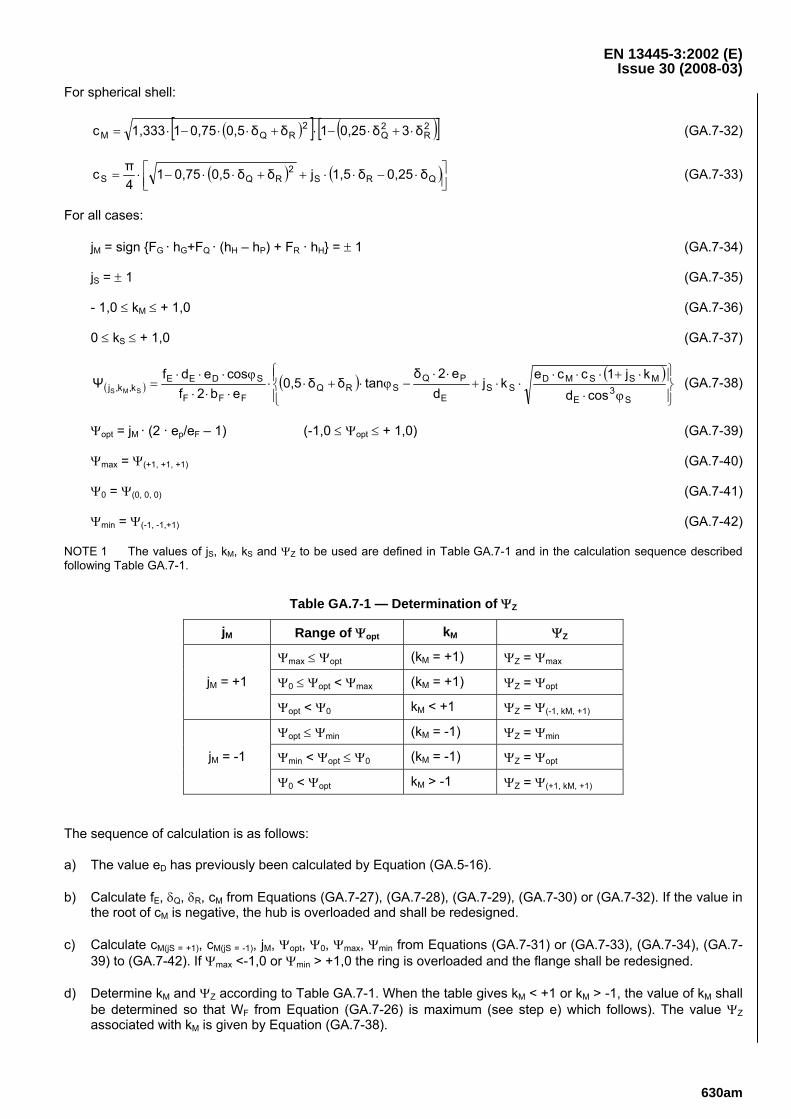
NOTE 1 The values of jS, kM, kS and ΨZ to be used are defined in Table GA.7-1 and in the calculation sequence described following Table GA.7-1.
Table GA.7-1 — Determination of ΨZ
jM Range of Ψopt kM ΨZ
Ψmax ≤ Ψopt (kM = +1) ΨZ = Ψmax
Ψ0 ≤ Ψopt < Ψmax (kM = +1) ΨZ = Ψopt jM = +1
Ψopt < Ψ0 kM < +1 ΨZ = Ψ(-1, kM, +1)
Ψopt ≤ Ψmin (kM = -1) ΨZ = Ψmin
Ψmin < Ψopt ≤ Ψ0 (kM = -1) ΨZ = Ψopt jM = -1
Ψ0 < Ψopt kM > -1 ΨZ = Ψ(+1, kM, +1)
The sequence of calculation is as follows:
a) The value eD has previously been calculated by Equation (GA.5-16).
b) Calculate fE, δQ, δR, cM from Equations (GA.7-27), (GA.7-28), (GA.7-29), (GA.7-30) or (GA.7-32). If the value in the root of cM is negative, the hub is overloaded and shall be redesigned.
c) Calculate cM(jS = +1), cM(jS = -1), jM, Ψopt, Ψ0, Ψmax, Ψmin from Equations (GA.7-31) or (GA.7-33), (GA.7-34), (GA.7-39) to (GA.7-42). If Ψmax <-1,0 or Ψmin > +1,0 the ring is overloaded and the flange shall be redesigned.
d) Determine kM and ΨZ according to Table GA.7-1. When the table gives kM < +1 or kM > -1, the value of kM shall be determined so that WF from Equation (GA.7-26) is maximum (see step e) which follows). The value ΨZ associated with kM is given by Equation (GA.7-38).
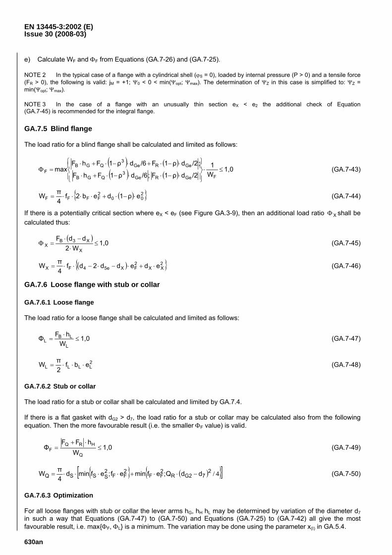
EN 13445-3:2002 (E) Issue 30 (2008-03)
630an
e) Calculate WF and ΦF from Equations (GA.7-26) and (GA.7-25).
NOTE 2 In the typical case of a flange with a cylindrical shell (ϕS = 0), loaded by internal pressure (P > 0) and a tensile force (FR > 0), the following is valid: jM = +1; Ψ0 < 0 < min(Ψopt; Ψmax). The determination of ΨZ in this case is simplified to: ΨZ = min(Ψopt; Ψmax).
NOTE 3 In the case of a flange with an unusually thin section eX < e2 the additional check of Equation (GA.7-45) is recommended for the integral flange.
GA.7.5 Blind flange
The load ratio for a blind flange shall be calculated and limited as follows:
( ) ( )( ) ( )
1,0W1
/2dρ1F;/6dρ1FhF
;/2dρ1F/6dρ1FhFmax
FGeRGe3
QGB
GeRGe3
QGBF ≤⋅
⎪⎭
⎪⎬⎫
⎪⎩
⎪⎨⎧
⋅−⋅⋅−⋅+⋅
⋅−⋅+⋅−⋅+⋅=Φ (GA.7-43)
( ){ }200
2FFFF eρ1deb2f
4πW ⋅−⋅+⋅⋅⋅⋅= (GA.7-44)
If there is a potentially critical section where eX < eF (see Figure GA.3-9), then an additional load ratio XΦ shall be calculated thus:
( )1,0
W2ddF
X
X3BX ≤
⋅−⋅
=Φ (GA.7-45)
( ){ }2XX
2FX5e4FX ededd2df
4πW ⋅+⋅−⋅−⋅⋅= (GA.7-46)
GA.7.6 Loose flange with stub or collar
GA.7.6.1 Loose flange
The load ratio for a loose flange shall be calculated and limited as follows:
1,0W
hFΦL
LBL ≤
⋅= (GA.7-47)
2LLLL ebf
2πW ⋅⋅⋅= (GA.7-48)
GA.7.6.2 Stub or collar
The load ratio for a stub or collar shall be calculated and limited by GA.7.4.
If there is a flat gasket with dG2 > d7, the load ratio for a stub or collar may be calculated also from the following equation. Then the more favourable result (i.e. the smaller ΦF value) is valid.
1,0W
hFFΦ
Q
HRQF ≤
⋅+= (GA.7-49)
{ } ( ){ }[ ]4/27G2R
2FF
2FF
2SSSQ ddQ;efminef;efmind
4πW −⋅⋅+⋅⋅⋅⋅= (GA.7-50)
GA.7.6.3 Optimization
For all loose flanges with stub or collar the lever arms hG, hH hL may be determined by variation of the diameter d7 in such a way that Equations (GA.7-47) to (GA.7-50) and Equations (GA.7-25) to (GA.7-42) all give the most favourable result, i.e. max{ΦF, ΦL} is a minimum. The variation may be done using the parameter x(Ι) in GA.5.4.
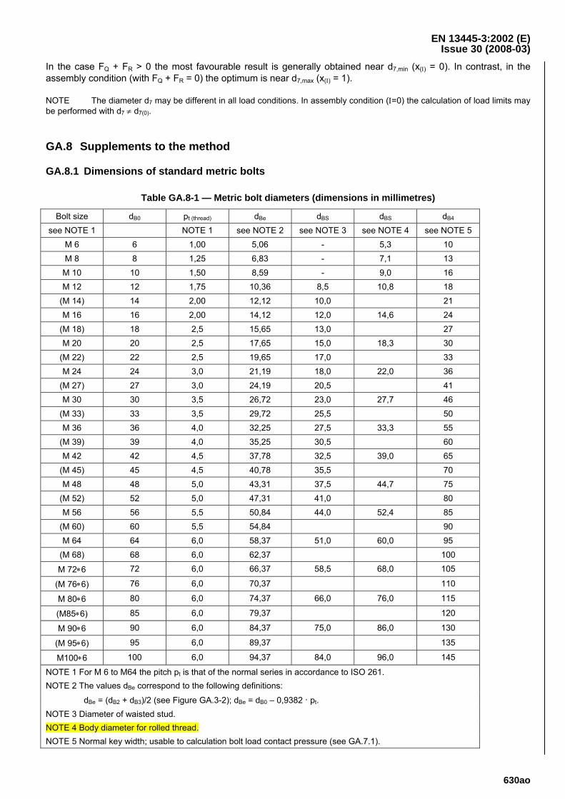
EN 13445-3:2002 (E) Issue 30 (2008-03)
630ao
In the case FQ + FR > 0 the most favourable result is generally obtained near d7,min (x(Ι) = 0). In contrast, in the assembly condition (with FQ + FR = 0) the optimum is near d7,max (x(Ι) = 1).
NOTE The diameter d7 may be different in all load conditions. In assembly condition (Ι=0) the calculation of load limits may be performed with d7 ≠ d7(0).
GA.8 Supplements to the method
GA.8.1 Dimensions of standard metric bolts
Table GA.8-1 — Metric bolt diameters (dimensions in millimetres)
Bolt size dB0 pt (thread) dBe dBS dBS dB4
see NOTE 1 NOTE 1 see NOTE 2 see NOTE 3 see NOTE 4 see NOTE 5 M 6 6 1,00 5,06 - 5,3 10 M 8 8 1,25 6,83 - 7,1 13
M 10 10 1,50 8,59 - 9,0 16 M 12 12 1,75 10,36 8,5 10,8 18
(M 14) 14 2,00 12,12 10,0 21 M 16 16 2,00 14,12 12,0 14,6 24
(M 18) 18 2,5 15,65 13,0 27 M 20 20 2,5 17,65 15,0 18,3 30
(M 22) 22 2,5 19,65 17,0 33 M 24 24 3,0 21,19 18,0 22,0 36
(M 27) 27 3,0 24,19 20,5 41 M 30 30 3,5 26,72 23,0 27,7 46
(M 33) 33 3,5 29,72 25,5 50 M 36 36 4,0 32,25 27,5 33,3 55
(M 39) 39 4,0 35,25 30,5 60 M 42 42 4,5 37,78 32,5 39,0 65
(M 45) 45 4,5 40,78 35,5 70 M 48 48 5,0 43,31 37,5 44,7 75
(M 52) 52 5,0 47,31 41,0 80 M 56 56 5,5 50,84 44,0 52,4 85
(M 60) 60 5,5 54,84 90 M 64 64 6,0 58,37 51,0 60,0 95
(M 68) 68 6,0 62,37 100
M 72∗6 72 6,0 66,37 58,5 68,0 105
(M 76∗6) 76 6,0 70,37 110
M 80∗6 80 6,0 74,37 66,0 76,0 115
(M85∗6) 85 6,0 79,37 120
M 90∗6 90 6,0 84,37 75,0 86,0 130
(M 95∗6) 95 6,0 89,37 135
M100∗6 100 6,0 94,37 84,0 96,0 145
NOTE 1 For M 6 to M64 the pitch pt is that of the normal series in accordance to ISO 261. NOTE 2 The values dBe correspond to the following definitions:
dBe = (dB2 + dB3)/2 (see Figure GA.3-2); dBe = dB0 – 0,9382 · pt. NOTE 3 Diameter of waisted stud. NOTE 4 Body diameter for rolled thread. NOTE 5 Normal key width; usable to calculation bolt load contact pressure (see GA.7.1).
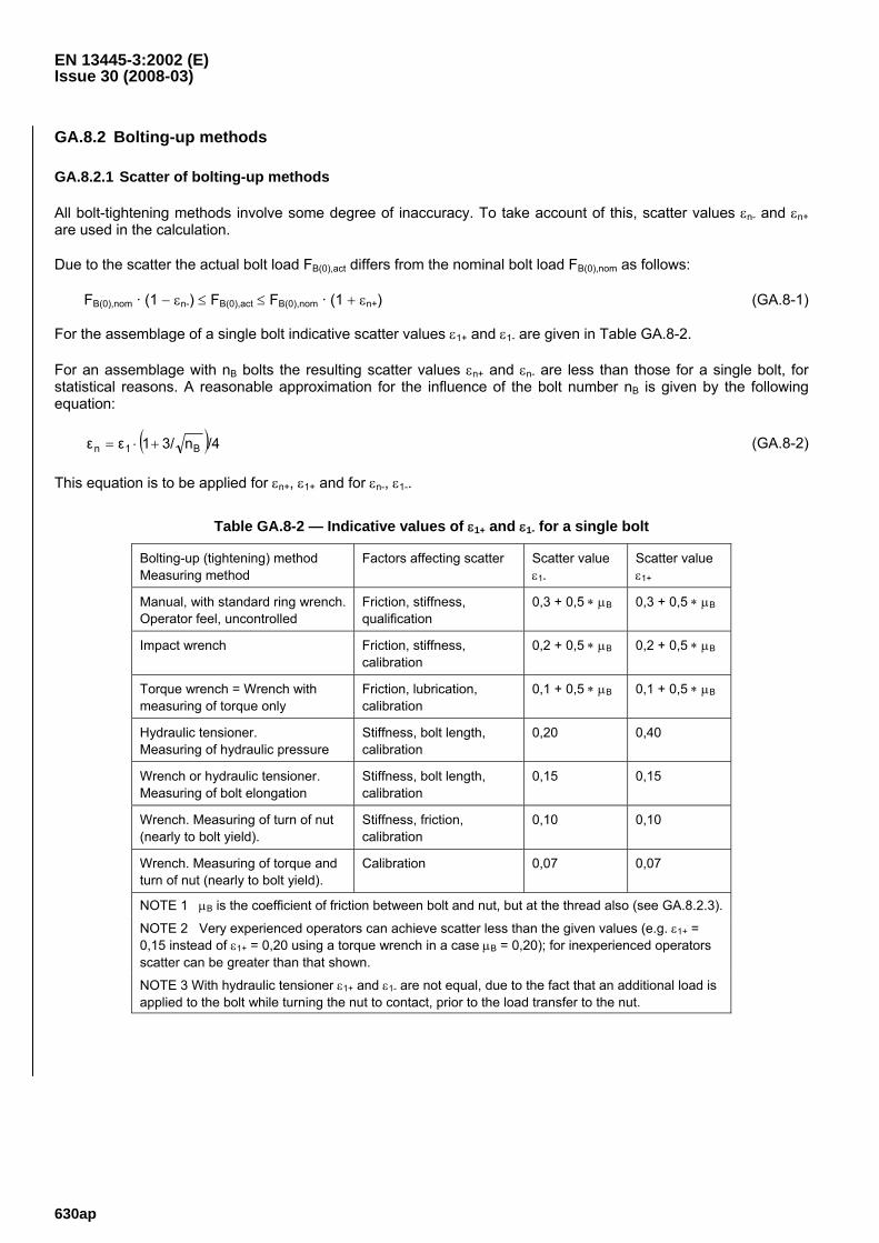
EN 13445-3:2002 (E) Issue 30 (2008-03)
630ap
GA.8.2 Bolting-up methods
GA.8.2.1 Scatter of bolting-up methods
All bolt-tightening methods involve some degree of inaccuracy. To take account of this, scatter values εn- and εn+ are used in the calculation.
Due to the scatter the actual bolt load FB(0),act differs from the nominal bolt load FB(0),nom as follows:
FB(0),nom · (1 − εn-) ≤ FB(0),act ≤ FB(0),nom · (1 + εn+) (GA.8-1)
For the assemblage of a single bolt indicative scatter values ε1+ and ε1- are given in Table GA.8-2.
For an assemblage with nB bolts the resulting scatter values εn+ and εn- are less than those for a single bolt, for statistical reasons. A reasonable approximation for the influence of the bolt number nB is given by the following equation:
( )/4n3/1εε B1n +⋅= (GA.8-2)
This equation is to be applied for εn+, ε1+ and for εn-, ε1-.
Table GA.8-2 — Indicative values of ε1+ and ε1- for a single bolt
Bolting-up (tightening) method Measuring method
Factors affecting scatter Scatter value ε1-
Scatter value ε1+
Manual, with standard ring wrench. Operator feel, uncontrolled
Friction, stiffness, qualification
0,3 + 0,5 ∗ μB 0,3 + 0,5 ∗ μB
Impact wrench Friction, stiffness, calibration
0,2 + 0,5 ∗ μB 0,2 + 0,5 ∗ μB
Torque wrench = Wrench with measuring of torque only
Friction, lubrication, calibration
0,1 + 0,5 ∗ μB 0,1 + 0,5 ∗ μB
Hydraulic tensioner. Measuring of hydraulic pressure
Stiffness, bolt length, calibration
0,20 0,40
Wrench or hydraulic tensioner. Measuring of bolt elongation
Stiffness, bolt length, calibration
0,15 0,15
Wrench. Measuring of turn of nut (nearly to bolt yield).
Stiffness, friction, calibration
0,10 0,10
Wrench. Measuring of torque and turn of nut (nearly to bolt yield).
Calibration 0,07 0,07
NOTE 1 μB is the coefficient of friction between bolt and nut, but at the thread also (see GA.8.2.3).
NOTE 2 Very experienced operators can achieve scatter less than the given values (e.g. ε1+ = 0,15 instead of ε1+ = 0,20 using a torque wrench in a case μB = 0,20); for inexperienced operators scatter can be greater than that shown.
NOTE 3 With hydraulic tensioner ε1+ and ε1- are not equal, due to the fact that an additional load is applied to the bolt while turning the nut to contact, prior to the load transfer to the nut.
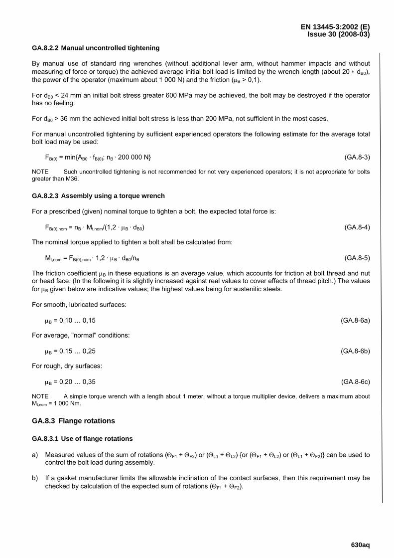
EN 13445-3:2002 (E) Issue 30 (2008-03)
630aq
GA.8.2.2 Manual uncontrolled tightening
By manual use of standard ring wrenches (without additional lever arm, without hammer impacts and without measuring of force or torque) the achieved average initial bolt load is limited by the wrench length (about 20 ∗ dB0), the power of the operator (maximum about 1 000 N) and the friction (μB > 0,1).
For dB0 < 24 mm an initial bolt stress greater 600 MPa may be achieved, the bolt may be destroyed if the operator has no feeling.
For dB0 > 36 mm the achieved initial bolt stress is less than 200 MPa, not sufficient in the most cases.
For manual uncontrolled tightening by sufficient experienced operators the following estimate for the average total bolt load may be used:
FB(0) = min{AB0 · fB(0); nB · 200 000 N} (GA.8-3)
NOTE Such uncontrolled tightening is not recommended for not very experienced operators; it is not appropriate for bolts greater than M36.
GA.8.2.3 Assembly using a torque wrench
For a prescribed (given) nominal torque to tighten a bolt, the expected total force is:
FB(0),nom = nB · Mt,nom/(1,2 · μB · dB0) (GA.8-4)
The nominal torque applied to tighten a bolt shall be calculated from:
Mt,nom = FB(0),nom · 1,2 · μB · dB0/nB (GA.8-5)
The friction coefficient μB in these equations is an average value, which accounts for friction at bolt thread and nut or head face. (In the following it is slightly increased against real values to cover effects of thread pitch.) The values for μB given below are indicative values; the highest values being for austenitic steels.
For smooth, lubricated surfaces:
μB = 0,10 … 0,15 (GA.8-6a)
For average, "normal" conditions:
μB = 0,15 … 0,25 (GA.8-6b)
For rough, dry surfaces:
μB = 0,20 … 0,35 (GA.8-6c)
NOTE A simple torque wrench with a length about 1 meter, without a torque multiplier device, delivers a maximum about Mt,nom = 1 000 Nm.
GA.8.3 Flange rotations
GA.8.3.1 Use of flange rotations
a) Measured values of the sum of rotations (ΘF1 + ΘF2) or (ΘL1 + ΘL2) {or (ΘF1 + ΘL2) or (ΘL1 + ΘF2)} can be used to control the bolt load during assembly.
b) If a gasket manufacturer limits the allowable inclination of the contact surfaces, then this requirement may be checked by calculation of the expected sum of rotations (ΘF1 + ΘF2).
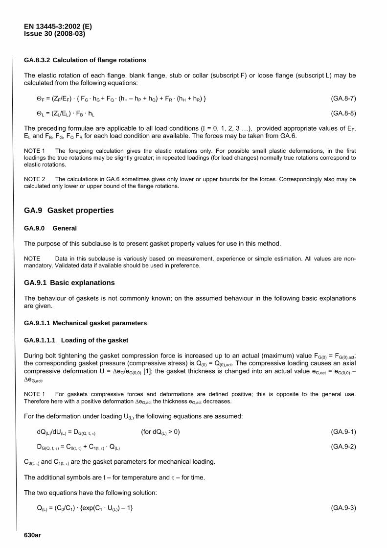
EN 13445-3:2002 (E) Issue 30 (2008-03)
630ar
GA.8.3.2 Calculation of flange rotations
The elastic rotation of each flange, blank flange, stub or collar (subscript F) or loose flange (subscript L) may be calculated from the following equations:
ΘF = (ZF/EF) · { FG · hG + FQ · (hH – hP + hQ) + FR · (hH + hR) } (GA.8-7)
ΘL = (ZL/EL) · FB · hL (GA.8-8)
The preceding formulae are applicable to all load conditions (Ι = 0, 1, 2, 3 …), provided appropriate values of EF, EL and FB, FG, FQ FR for each load condition are available. The forces may be taken from GA.6.
NOTE 1 The foregoing calculation gives the elastic rotations only. For possible small plastic deformations, in the first loadings the true rotations may be slightly greater; in repeated loadings (for load changes) normally true rotations correspond to elastic rotations.
NOTE 2 The calculations in GA.6 sometimes gives only lower or upper bounds for the forces. Correspondingly also may be calculated only lower or upper bound of the flange rotations.
GA.9 Gasket properties
GA.9.0 General
The purpose of this subclause is to present gasket property values for use in this method.
NOTE Data in this subclause is variously based on measurement, experience or simple estimation. All values are non-mandatory. Validated data if available should be used in preference.
GA.9.1 Basic explanations
The behaviour of gaskets is not commonly known; on the assumed behaviour in the following basic explanations are given.
GA.9.1.1 Mechanical gasket parameters
GA.9.1.1.1 Loading of the gasket
During bolt tightening the gasket compression force is increased up to an actual (maximum) value FG(0) = FG(0),act; the corresponding gasket pressure (compressive stress) is Q(0) = Q(0),act. The compressive loading causes an axial compressive deformation U = ΔeG/eG(0,0) [1]; the gasket thickness is changed into an actual value eG,act = eG(0,0) − ΔeG,act.
NOTE 1 For gaskets compressive forces and deformations are defined positive; this is opposite to the general use. Therefore here with a positive deformation ΔeG,act the thickness eG,act decreases.
For the deformation under loading U(L) the following equations are assumed:
dQ(L)/dU(L) = DG(Q, t, τ) (for dQ(L) > 0) (GA.9-1)
DG(Q, t, τ) = C0(t, τ) + C1(t, τ) · Q(L) (GA.9-2)
C0(t, τ) and C1(t, τ) are the gasket parameters for mechanical loading.
The additional symbols are t – for temperature and τ – for time.
The two equations have the following solution:
Q(L) = (C0/C1) · {exp(C1 · U(L)) – 1} (GA.9-3)
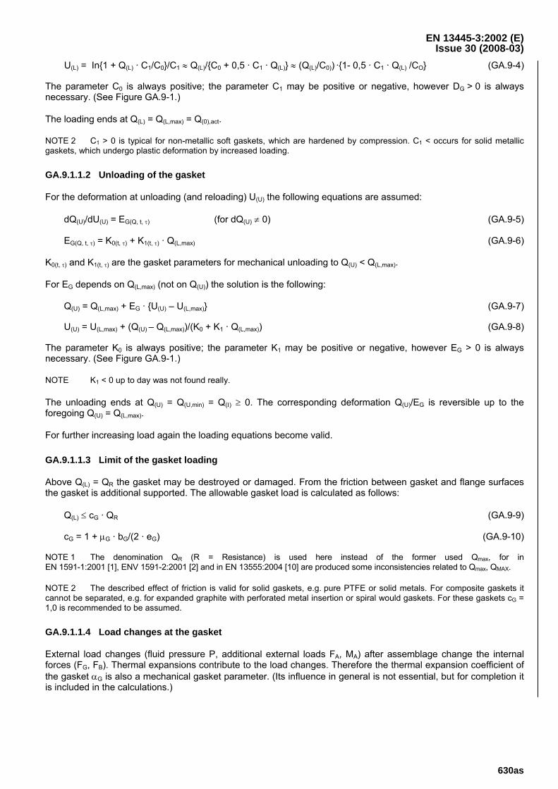
EN 13445-3:2002 (E) Issue 30 (2008-03)
630as
U(L) = In{1 + Q(L) · C1/C0}/C1 ≈ Q(L)/{C0 + 0,5 · C1 · Q(L)} ≈ (Q(L)/C0)) ·{1- 0,5 · C1 · Q(L) /CO} (GA.9-4)
The parameter C0 is always positive; the parameter C1 may be positive or negative, however DG > 0 is always necessary. (See Figure GA.9-1.)
The loading ends at Q(L) = Q(L,max) = Q(0),act.
NOTE 2 C1 > 0 is typical for non-metallic soft gaskets, which are hardened by compression. C1 < occurs for solid metallic gaskets, which undergo plastic deformation by increased loading.
GA.9.1.1.2 Unloading of the gasket
For the deformation at unloading (and reloading) U(U) the following equations are assumed:
dQ(U)/dU(U) = EG(Q, t, τ) (for dQ(U) ≠ 0) (GA.9-5)
EG(Q, t, τ) = K0(t, τ) + K1(t, τ) · Q(L,max) (GA.9-6)
K0(t, τ) and K1(t, τ) are the gasket parameters for mechanical unloading to Q(U) < Q(L,max).
For EG depends on Q(L,max) (not on Q(U)) the solution is the following:
Q(U) = Q(L,max) + EG · {U(U) – U(L,max)} (GA.9-7)
U(U) = U(L,max) + (Q(U) – Q(L,max))/(K0 + K1 · Q(L,max)) (GA.9-8)
The parameter K0 is always positive; the parameter K1 may be positive or negative, however EG > 0 is always necessary. (See Figure GA.9-1.)
NOTE K1 < 0 up to day was not found really.
The unloading ends at Q(U) = Q(U,min) = Q(Ι) ≥ 0. The corresponding deformation Q(U)/EG is reversible up to the foregoing Q(U) = Q(L,max).
For further increasing load again the loading equations become valid.
GA.9.1.1.3 Limit of the gasket loading
Above Q(L) = QR the gasket may be destroyed or damaged. From the friction between gasket and flange surfaces the gasket is additional supported. The allowable gasket load is calculated as follows:
Q(L) ≤ cG · QR (GA.9-9)
cG = 1 + μG · bG/(2 · eG) (GA.9-10)
NOTE 1 The denomination QR (R = Resistance) is used here instead of the former used Qmax, for in EN 1591-1:2001 [1], ENV 1591-2:2001 [2] and in EN 13555:2004 [10] are produced some inconsistencies related to Qmax, QMAX.
NOTE 2 The described effect of friction is valid for solid gaskets, e.g. pure PTFE or solid metals. For composite gaskets it cannot be separated, e.g. for expanded graphite with perforated metal insertion or spiral would gaskets. For these gaskets cG = 1,0 is recommended to be assumed.
GA.9.1.1.4 Load changes at the gasket
External load changes (fluid pressure P, additional external loads FA, MA) after assemblage change the internal forces (FG, FB). Thermal expansions contribute to the load changes. Therefore the thermal expansion coefficient of the gasket αG is also a mechanical gasket parameter. (Its influence in general is not essential, but for completion it is included in the calculations.)
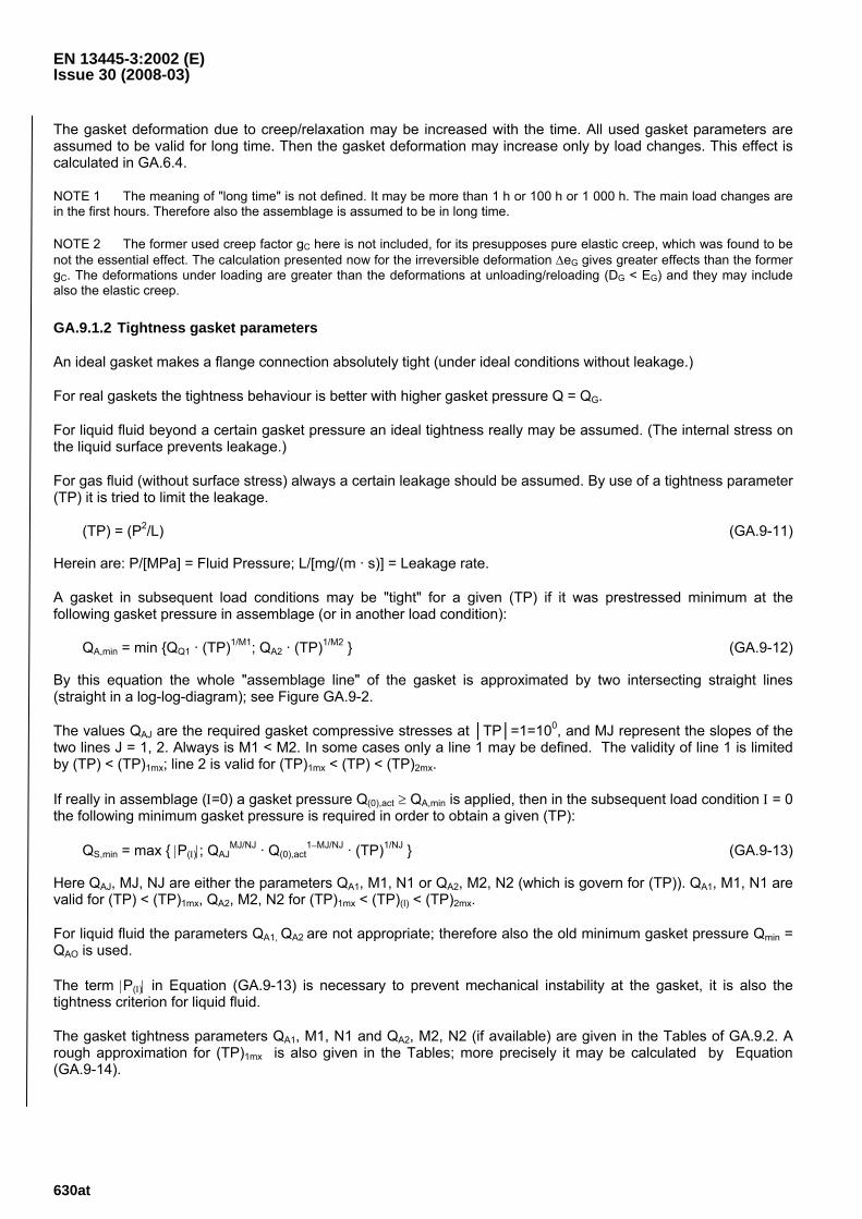
EN 13445-3:2002 (E) Issue 30 (2008-03)
630at
The gasket deformation due to creep/relaxation may be increased with the time. All used gasket parameters are assumed to be valid for long time. Then the gasket deformation may increase only by load changes. This effect is calculated in GA.6.4.
NOTE 1 The meaning of "long time" is not defined. It may be more than 1 h or 100 h or 1 000 h. The main load changes are in the first hours. Therefore also the assemblage is assumed to be in long time.
NOTE 2 The former used creep factor gC here is not included, for its presupposes pure elastic creep, which was found to be not the essential effect. The calculation presented now for the irreversible deformation ΔeG gives greater effects than the former gC. The deformations under loading are greater than the deformations at unloading/reloading (DG < EG) and they may include also the elastic creep.
GA.9.1.2 Tightness gasket parameters
An ideal gasket makes a flange connection absolutely tight (under ideal conditions without leakage.)
For real gaskets the tightness behaviour is better with higher gasket pressure Q = QG.
For liquid fluid beyond a certain gasket pressure an ideal tightness really may be assumed. (The internal stress on the liquid surface prevents leakage.)
For gas fluid (without surface stress) always a certain leakage should be assumed. By use of a tightness parameter (TP) it is tried to limit the leakage.
(TP) = (P2/L) (GA.9-11)
Herein are: P/[MPa] = Fluid Pressure; L/[mg/(m · s)] = Leakage rate.
A gasket in subsequent load conditions may be "tight" for a given (TP) if it was prestressed minimum at the following gasket pressure in assemblage (or in another load condition):
QA,min = min {QQ1 · (TP)1/M1; QA2 · (TP)1/M2 } (GA.9-12)
By this equation the whole "assemblage line" of the gasket is approximated by two intersecting straight lines (straight in a log-log-diagram); see Figure GA.9-2.
The values QAJ are the required gasket compressive stresses at │TP│=1=100, and MJ represent the slopes of the two lines J = 1, 2. Always is M1 < M2. In some cases only a line 1 may be defined. The validity of line 1 is limited by (TP) < (TP)1mx; line 2 is valid for (TP)1mx < (TP) < (TP)2mx.
If really in assemblage (Ι=0) a gasket pressure Q(0),act ≥ QA,min is applied, then in the subsequent load condition Ι = 0 the following minimum gasket pressure is required in order to obtain a given (TP):
QS,min = max { |P(Ι)|; QAJMJ/NJ · Q(0),act
1−MJ/NJ · (TP)1/NJ } (GA.9-13)
Here QAJ, MJ, NJ are either the parameters QA1, M1, N1 or QA2, M2, N2 (which is govern for (TP)). QA1, M1, N1 are valid for (TP) < (TP)1mx, QA2, M2, N2 for (TP)1mx < (TP)(I) < (TP)2mx.
For liquid fluid the parameters QA1, QA2 are not appropriate; therefore also the old minimum gasket pressure Qmin = QAO is used.
The term |P(Ι)| in Equation (GA.9-13) is necessary to prevent mechanical instability at the gasket, it is also the tightness criterion for liquid fluid.
The gasket tightness parameters QA1, M1, N1 and QA2, M2, N2 (if available) are given in the Tables of GA.9.2. A rough approximation for (TP)1mx is also given in the Tables; more precisely it may be calculated by Equation (GA.9-14).
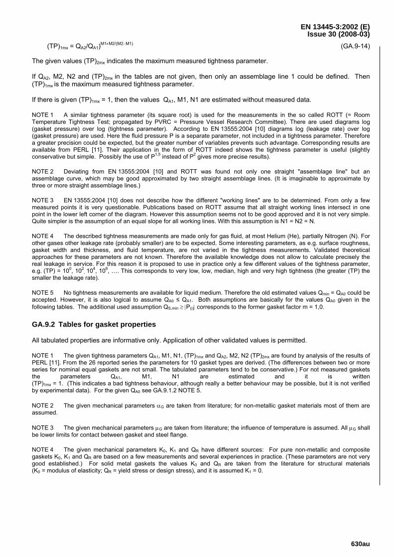
EN 13445-3:2002 (E) Issue 30 (2008-03)
630au
(TP)1mx = QA2/QA1)M1∗M2/(M2−M1) (GA.9-14)
The given values (TP)2mx indicates the maximum measured tightness parameter.
If QA2, M2, N2 and (TP)2mx in the tables are not given, then only an assemblage line 1 could be defined. Then (TP)1mx is the maximum measured tightness parameter.
If there is given (TP)1mx = 1, then the values QA1, M1, N1 are estimated without measured data.
NOTE 1 A similar tightness parameter (its square root) is used for the measurements in the so called ROTT (= Room Temperature Tightness Test; propagated by PVRC = Pressure Vessel Research Committee). There are used diagrams log (gasket pressure) over log (tightness parameter). According to EN 13555:2004 [10] diagrams log (leakage rate) over log (gasket pressure) are used. Here the fluid pressure P is a separate parameter, not included in a tightness parameter. Therefore a greater precision could be expected, but the greater number of variables prevents such advantage. Corresponding results are available from PERL [11]. Their application in the form of ROTT indeed shows the tightness parameter is useful (slightly conservative but simple. Possibly the use of P1,5 instead of P2 gives more precise results).
NOTE 2 Deviating from EN 13555:2004 [10] and ROTT was found not only one straight "assemblage line" but an assemblage curve, which may be good approximated by two straight assemblage lines. (It is imaginable to approximate by three or more straight assemblage lines.)
NOTE 3 EN 13555:2004 [10] does not describe how the different "working lines" are to be determined. From only a few measured points it is very questionable. Publications based on ROTT assume that all straight working lines intersect in one point in the lower left corner of the diagram. However this assumption seems not to be good approved and it is not very simple. Quite simpler is the assumption of an equal slope for all working lines. With this assumption is N1 = N2 = N.
NOTE 4 The described tightness measurements are made only for gas fluid, at most Helium (He), partially Nitrogen (N). For other gases other leakage rate (probably smaller) are to be expected. Some interesting parameters, as e.g. surface roughness, gasket width and thickness, and fluid temperature, are not varied in the tightness measurements. Validated theoretical approaches for these parameters are not known. Therefore the available knowledge does not allow to calculate precisely the real leakage in service. For this reason it is proposed to use in practice only a few different values of the tightness parameter, e.g. (TP) = 100, 102
, 104, 108, …. This corresponds to very low, low, median, high and very high tightness (the greater (TP) the smaller the leakage rate).
NOTE 5 No tightness measurements are available for liquid medium. Therefore the old estimated values Qmin = QA0 could be accepted. However, it is also logical to assume QA0 ≤ QA1. Both assumptions are basically for the values QA0 given in the following tables. The additional used assumption QS,min ≥ |P(Ι)| corresponds to the former gasket factor m = 1,0.
GA.9.2 Tables for gasket properties
All tabulated properties are informative only. Application of other validated values is permitted.
NOTE 1 The given tightness parameters QA1, M1, N1, (TP)1mx and QA2, M2, N2 (TP)2mx are found by analysis of the results of PERL [11]. From the 26 reported series the parameters for 10 gasket types are derived. (The differences between two or more series for nominal equal gaskets are not small. The tabulated parameters tend to be conservative.) For not measured gaskets the parameters QA1, M1, N1 are estimated and it is written (TP)1mx = 1. (This indicates a bad tightness behaviour, although really a better behaviour may be possible, but it is not verified by experimental data). For the given QA0 see GA.9.1.2 NOTE 5.
NOTE 2 The given mechanical parameters αG are taken from literature; for non-metallic gasket materials most of them are assumed.
NOTE 3 The given mechanical parameters μG are taken from literature; the influence of temperature is assumed. All μG shall be lower limits for contact between gasket and steel flange.
NOTE 4 The given mechanical parameters K0, K1 and QR have different sources: For pure non-metallic and composite gaskets K0, K1 and QR are based on a few measurements and several experiences in practice. (These parameters are not very good established.) For solid metal gaskets the values K0 and QR are taken from the literature for structural materials (K0 = modulus of elasticity; QR = yield stress or design stress), and it is assumed K1 = 0.
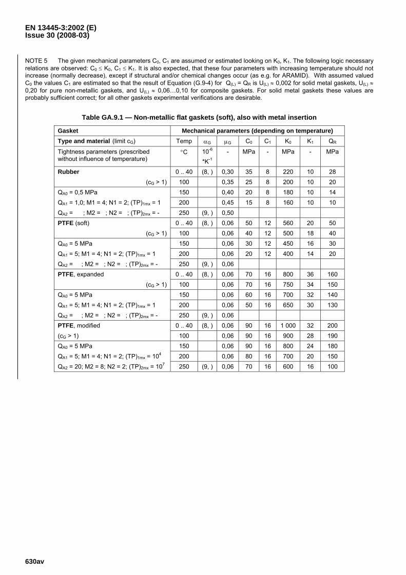
EN 13445-3:2002 (E) Issue 30 (2008-03)
630av
NOTE 5 The given mechanical parameters C0, C1 are assumed or estimated looking on K0, K1. The following logic necessary relations are observed: C0 ≤ K0, C1 ≤ K1. It is also expected, that these four parameters with increasing temperature should not increase (normally decrease), except if structural and/or chemical changes occur (as e.g. for ARAMID). With assumed valued C0 the values C1 are estimated so that the result of Equation (G.9-4) for Q(L) = QR is U(L) ≈ 0,002 for solid metal gaskets, U(L) ≈ 0,20 for pure non-metallic gaskets, and U(L) ≈ 0,06…0,10 for composite gaskets. For solid metal gaskets these values are probably sufficient correct; for all other gaskets experimental verifications are desirable.
Table GA.9.1 — Non-metallic flat gaskets (soft), also with metal insertion
Gasket Mechanical parameters (depending on temperature) Type and material (limit cG) Temp αG μG C0 C1 K0 K1 QR
Tightness parameters (prescribed without influence of temperature)
°C 10-6 *K-1
- MPa - MPa - MPa
Rubber 0 .. 40 (8, ) 0,30 35 8 220 10 28
(cG > 1) 100 0,35 25 8 200 10 20
QA0 = 0,5 MPa 150 0,40 20 8 180 10 14
QA1 = 1,0; M1 = 4; N1 = 2; (TP)1mx = 1 200 0,45 15 8 160 10 10
QA2 = ; M2 = ; N2 = ; (TP)2mx = - 250 (9, ) 0,50 PTFE (soft) 0 .. 40 (8, ) 0,06 50 12 560 20 50
(cG > 1) 100 0,06 40 12 500 18 40
QA0 = 5 MPa 150 0,06 30 12 450 16 30
QA1 = 5; M1 = 4; N1 = 2; (TP)1mx = 1 200 0,06 20 12 400 14 20
QA2 = ; M2 = ; N2 = ; (TP)2mx = - 250 (9, ) 0,06 PTFE, expanded 0 .. 40 (8, ) 0,06 70 16 800 36 160
(cG > 1) 100 0,06 70 16 750 34 150
QA0 = 5 MPa 150 0,06 60 16 700 32 140
QA1 = 5; M1 = 4; N1 = 2; (TP)1mx = 1 200 0,06 50 16 650 30 130
QA2 = ; M2 = ; N2 = ; (TP)2mx = - 250 (9, ) 0,06 PTFE, modified 0 .. 40 (8, ) 0,06 90 16 1 000 32 200
(cG > 1) 100 0,06 90 16 900 28 190
QA0 = 5 MPa 150 0,06 90 16 800 24 180
QA1 = 5; M1 = 4; N1 = 2; (TP)1mx = 104 200 0,06 80 16 700 20 150
QA2 = 20; M2 = 8; N2 = 2; (TP)2mx = 107 250 (9, ) 0,06 70 16 600 16 100
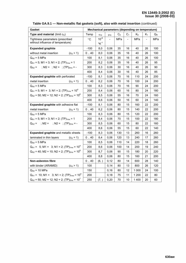
EN 13445-3:2002 (E) Issue 30 (2008-03)
630aw
Table GA.9.1 — Non-metallic flat gaskets (soft), also with metal insertion (continued)
Gasket Mechanical parameters (depending on temperature) Type and material (limit cG) Temp αG μG C0 C1 K0 K1 QR
Tightness parameters (prescribed without influence of temperature)
°C 10-6
*K-1
- MPa - MPa - MPa
Expanded graphite -100 8,0 0,06 35 16 40 26 100
without metal insertion (cG > 1) 0 .. 40 8,0 0,06 35 16 40 26 100
QA0 = 5 MPa 100 8,1 0,06 35 16 40 26 100
QA1 = 5; M1 = 3; N1 = 2; (TP)1mx = 1 200 8,2 0,06 35 16 40 26 95
QA2 = ; M2 = ; N2 = ; (TP)2mx = - 300 8,3 0,06 30 16 40 26 90
400 8,4 0,06 30 16 40 26 85 Expanded graphite with perforated -100 8,1 0,06 70 16 110 24 200
metal insertion (cG = 1) 0 .. 40 8,2 0,06 70 16 100 24 200
QA0 = 5 MPa 100 8,3 0,06 70 16 90 24 200
QA1 = 5; M1 = 3; N1 = 2; (TP)1mx = 104 200 8,4 0,06 60 16 80 24 180
QA2 = 50; M2 = 12; N2 = 2; (TP)2mx = 106 300 8,5 0,06 55 16 70 24 160
400 8,6 0,06 50 16 60 24 140 Expanded graphite with adhesive flat -100 8,1 0,06 80 15 160 22 200
metal insertion (cG = 1) 0 .. 40 8,2 0,06 80 15 140 22 200
QA0 = 5 MPa 100 8,3 0,06 80 15 120 22 200
QA1 = 5; M1 = 3; N1 = 2; (TP)1mx = 1 200 8,4 0,06 70 15 100 22 180
QA2 = ; M2 = ; N2 = ; (TP)2mx = - 300 8,5 0,06 60 15 80 22 160
400 8,6 0,06 55 15 60 22 140 Expanded graphite and metallic sheets -100 8,3 0,06 130 13 260 16 260
laminated in thin layers (cG = 1) 0 .. 40 8,4 0,06 120 13 240 17 260
QA0 = 5 MPa 100 8,5 0,06 110 14 220 18 260
QA1 = 5; M1 = 3; N1 = 2; (TP)1mx = 104 200 8,6 0,06 100 14 200 19 240
QA2 = 40; M2 = 10; N2 = 2; (TP)2mx = 108 300 8,7 0,06 90 15 180 20 220
400 8,8 0,06 80 15 160 21 200 Non-asbestos fibre 0 .. 40 (6, ) 0,12 80 14 600 28 140
with binder (ARAMID) (cG > 1) 100 0,14 80 13 800 26 120
QA0 = 10 MPa 150 0,16 80 12 1 000 24 100
QA1 = 10; M1 = 3; N1 = 2; (TP)1mx = 104 200 0,18 75 11 1 200 22 80
QA2 = 50; M2 = 12; N2 = 2; (TP)2mx = 107 250 (7, ) 0,20 70 10 1 400 20 60
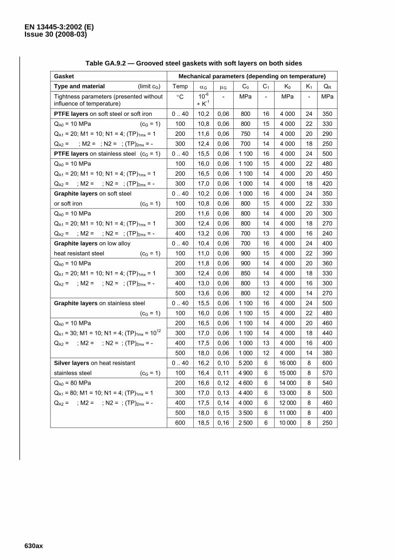
EN 13445-3:2002 (E) Issue 30 (2008-03)
630ax
Table GA.9.2 — Grooved steel gaskets with soft layers on both sides
Gasket Mechanical parameters (depending on temperature) Type and material (limit cG) Temp αG μG C0 C1 K0 K1 QR
Tightness parameters (presented without influence of temperature)
°C 10-6 ∗ K-1
- MPa - MPa - MPa
PTFE layers on soft steel or soft iron 0 .. 40 10,2 0,06 800 16 4 000 24 350
QA0 = 10 MPa (cG = 1) 100 10,8 0,06 800 15 4 000 22 330
QA1 = 20; M1 = 10; N1 = 4; (TP)1mx = 1 200 11,6 0,06 750 14 4 000 20 290
QA2 = ; M2 = ; N2 = ; (TP)2mx = - 300 12,4 0,06 700 14 4 000 18 250 PTFE layers on stainless steel (cG = 1) 0 .. 40 15,5 0,06 1 100 16 4 000 24 500
QA0 = 10 MPa 100 16,0 0,06 1 100 15 4 000 22 480
QA1 = 20; M1 = 10; N1 = 4; (TP)1mx = 1 200 16,5 0,06 1 100 14 4 000 20 450
QA2 = ; M2 = ; N2 = ; (TP)2mx = - 300 17,0 0,06 1 000 14 4 000 18 420 Graphite layers on soft steel 0 .. 40 10,2 0,06 1 000 16 4 000 24 350
or soft iron (cG = 1) 100 10,8 0,06 800 15 4 000 22 330
QA0 = 10 MPa 200 11,6 0,06 800 14 4 000 20 300
QA1 = 20; M1 = 10; N1 = 4; (TP)1mx = 1 300 12,4 0,06 800 14 4 000 18 270
QA2 = ; M2 = ; N2 = ; (TP)2mx = - 400 13,2 0,06 700 13 4 000 16 240 Graphite layers on low alloy 0 .. 40 10,4 0,06 700 16 4 000 24 400
heat resistant steel (cG = 1) 100 11,0 0,06 900 15 4 000 22 390
QA0 = 10 MPa 200 11,8 0,06 900 14 4 000 20 360
QA1 = 20; M1 = 10; N1 = 4; (TP)1mx = 1 300 12,4 0,06 850 14 4 000 18 330
QA2 = ; M2 = ; N2 = ; (TP)2mx = - 400 13,0 0,06 800 13 4 000 16 300
500 13,6 0,06 800 12 4 000 14 270 Graphite layers on stainless steel 0 .. 40 15,5 0,06 1 100 16 4 000 24 500
(cG = 1) 100 16,0 0,06 1 100 15 4 000 22 480
QA0 = 10 MPa 200 16,5 0,06 1 100 14 4 000 20 460
QA1 = 30; M1 = 10; N1 = 4; (TP)1mx = 1012 300 17,0 0,06 1 100 14 4 000 18 440
QA2 = ; M2 = ; N2 = ; (TP)2mx = - 400 17,5 0,06 1 000 13 4 000 16 400
500 18,0 0,06 1 000 12 4 000 14 380 Silver layers on heat resistant 0 .. 40 16,2 0,10 5 200 6 16 000 8 600
stainless steel (cG = 1) 100 16,4 0,11 4 900 6 15 000 8 570
QA0 = 80 MPa 200 16,6 0,12 4 600 6 14 000 8 540
QA1 = 80; M1 = 10; N1 = 4; (TP)1mx = 1 300 17,0 0,13 4 400 6 13 000 8 500
QA2 = ; M2 = ; N2 = ; (TP)2mx = - 400 17,5 0,14 4 000 6 12 000 8 460
500 18,0 0,15 3 500 6 11 000 8 400
600 18,5 0,16 2 500 6 10 000 8 250
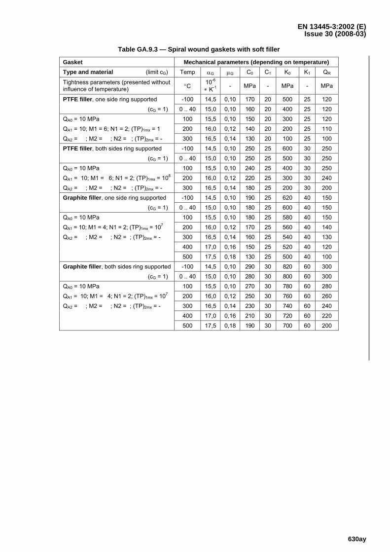
EN 13445-3:2002 (E) Issue 30 (2008-03)
630ay
Table GA.9.3 — Spiral wound gaskets with soft filler
Gasket Mechanical parameters (depending on temperature) Type and material (limit cG) Temp αG μG C0 C1 K0 K1 QR
Tightness parameters (presented without influence of temperature) °C 10-6
∗ K-1 - MPa - MPa - MPa
PTFE filler, one side ring supported -100 14,5 0,10 170 20 500 25 120
(cG = 1) 0 .. 40 15,0 0,10 160 20 400 25 120
QA0 = 10 MPa 100 15,5 0,10 150 20 300 25 120
QA1 = 10; M1 = 6; N1 = 2; (TP)1mx = 1 200 16,0 0,12 140 20 200 25 110
QA2 = ; M2 = ; N2 = ; (TP)2mx = - 300 16,5 0,14 130 20 100 25 100 PTFE filler, both sides ring supported -100 14,5 0,10 250 25 600 30 250
(cG = 1) 0 .. 40 15,0 0,10 250 25 500 30 250
QA0 = 10 MPa 100 15,5 0,10 240 25 400 30 250
QA1 = 10; M1 = 6; N1 = 2; (TP)1mx = 108 200 16,0 0,12 220 25 300 30 240
QA2 = ; M2 = ; N2 = ; (TP)2mx = - 300 16,5 0,14 180 25 200 30 200 Graphite filler, one side ring supported -100 14,5 0,10 190 25 620 40 150
(cG = 1) 0 .. 40 15,0 0,10 180 25 600 40 150
QA0 = 10 MPa 100 15,5 0,10 180 25 580 40 150
QA1 = 10; M1 = 4; N1 = 2; (TP)1mx = 107 200 16,0 0,12 170 25 560 40 140
QA2 = ; M2 = ; N2 = ; (TP)2mx = - 300 16,5 0,14 160 25 540 40 130
400 17,0 0,16 150 25 520 40 120
500 17,5 0,18 130 25 500 40 100 Graphite filler, both sides ring supported -100 14,5 0,10 290 30 820 60 300
(cG = 1) 0 .. 40 15,0 0,10 280 30 800 60 300
QA0 = 10 MPa 100 15,5 0,10 270 30 780 60 280
QA1 = 10; M1 = 4; N1 = 2; (TP)1mx = 107 200 16,0 0,12 250 30 760 60 260
QA2 = ; M2 = ; N2 = ; (TP)2mx = - 300 16,5 0,14 230 30 740 60 240
400 17,0 0,16 210 30 720 60 220
500 17,5 0,18 190 30 700 60 200
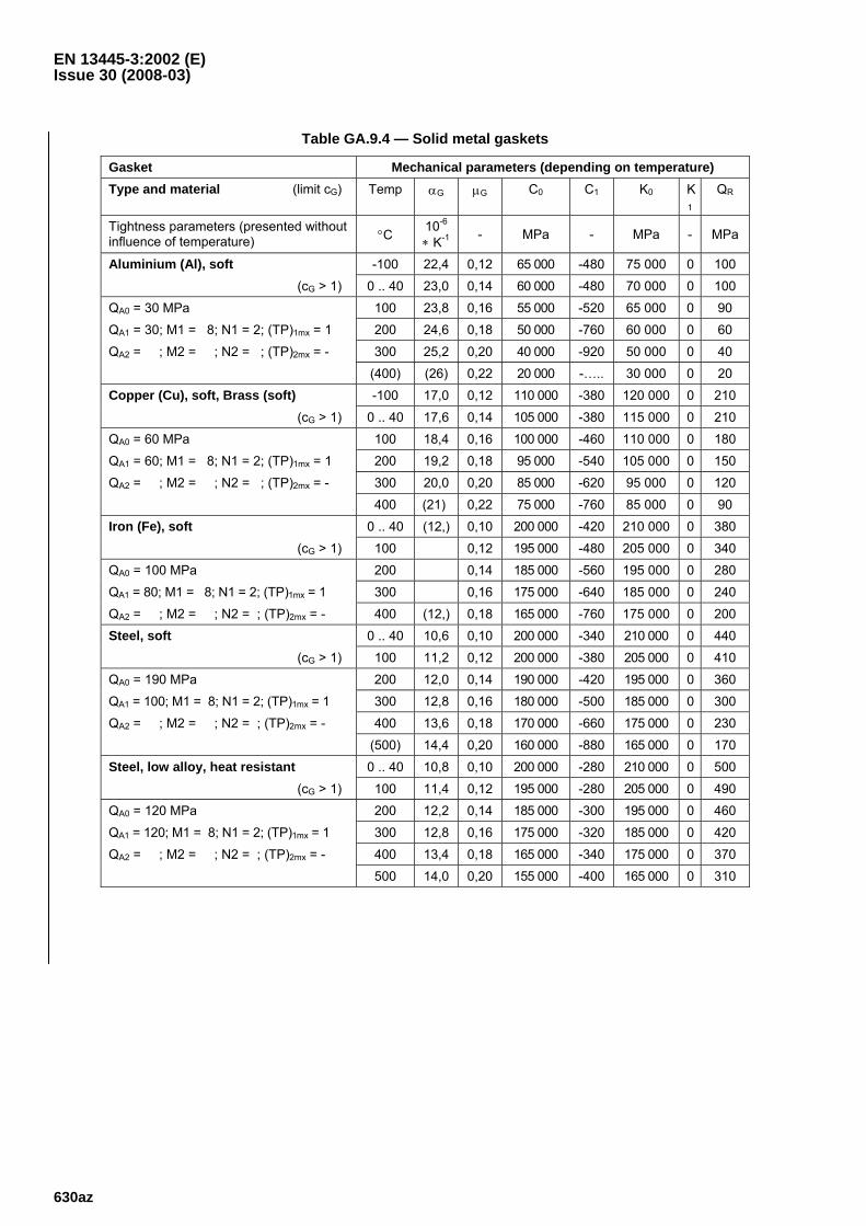
EN 13445-3:2002 (E) Issue 30 (2008-03)
630az
Table GA.9.4 — Solid metal gaskets
Gasket Mechanical parameters (depending on temperature) Type and material (limit cG) Temp αG μG C0 C1 K0 K
1
QR
Tightness parameters (presented without influence of temperature) °C 10-6
∗ K-1 - MPa - MPa - MPa
Aluminium (Al), soft -100 22,4 0,12 65 000 -480 75 000 0 100
(cG > 1) 0 .. 40 23,0 0,14 60 000 -480 70 000 0 100
QA0 = 30 MPa 100 23,8 0,16 55 000 -520 65 000 0 90
QA1 = 30; M1 = 8; N1 = 2; (TP)1mx = 1 200 24,6 0,18 50 000 -760 60 000 0 60
QA2 = ; M2 = ; N2 = ; (TP)2mx = - 300 25,2 0,20 40 000 -920 50 000 0 40
(400) (26) 0,22 20 000 -….. 30 000 0 20 Copper (Cu), soft, Brass (soft) -100 17,0 0,12 110 000 -380 120 000 0 210
(cG > 1) 0 .. 40 17,6 0,14 105 000 -380 115 000 0 210
QA0 = 60 MPa 100 18,4 0,16 100 000 -460 110 000 0 180
QA1 = 60; M1 = 8; N1 = 2; (TP)1mx = 1 200 19,2 0,18 95 000 -540 105 000 0 150
QA2 = ; M2 = ; N2 = ; (TP)2mx = - 300 20,0 0,20 85 000 -620 95 000 0 120
400 (21) 0,22 75 000 -760 85 000 0 90 Iron (Fe), soft 0 .. 40 (12,) 0,10 200 000 -420 210 000 0 380
(cG > 1) 100 0,12 195 000 -480 205 000 0 340
QA0 = 100 MPa 200 0,14 185 000 -560 195 000 0 280
QA1 = 80; M1 = 8; N1 = 2; (TP)1mx = 1 300 0,16 175 000 -640 185 000 0 240
QA2 = ; M2 = ; N2 = ; (TP)2mx = - 400 (12,) 0,18 165 000 -760 175 000 0 200 Steel, soft 0 .. 40 10,6 0,10 200 000 -340 210 000 0 440
(cG > 1) 100 11,2 0,12 200 000 -380 205 000 0 410
QA0 = 190 MPa 200 12,0 0,14 190 000 -420 195 000 0 360
QA1 = 100; M1 = 8; N1 = 2; (TP)1mx = 1 300 12,8 0,16 180 000 -500 185 000 0 300
QA2 = ; M2 = ; N2 = ; (TP)2mx = - 400 13,6 0,18 170 000 -660 175 000 0 230
(500) 14,4 0,20 160 000 -880 165 000 0 170 Steel, low alloy, heat resistant 0 .. 40 10,8 0,10 200 000 -280 210 000 0 500
(cG > 1) 100 11,4 0,12 195 000 -280 205 000 0 490
QA0 = 120 MPa 200 12,2 0,14 185 000 -300 195 000 0 460
QA1 = 120; M1 = 8; N1 = 2; (TP)1mx = 1 300 12,8 0,16 175 000 -320 185 000 0 420
QA2 = ; M2 = ; N2 = ; (TP)2mx = - 400 13,4 0,18 165 000 -340 175 000 0 370
500 14,0 0,20 155 000 -400 165 000 0 310
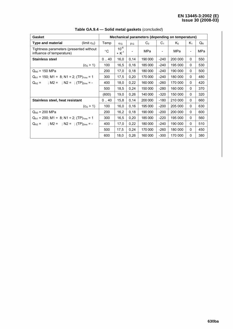
EN 13445-3:2002 (E) Issue 30 (2008-03)
630ba
Table GA.9.4 — Solid metal gaskets (concluded)
Gasket Mechanical parameters (depending on temperature) Type and material (limit cG) Temp αG μG C0 C1 K0 K1 QR
Tightness parameters (presented without influence of temperature) °C 10-6
∗ K-1 - MPa - MPa - MPa
Stainless steel 0 .. 40 16,0 0,14 190 000 -240 200 000 0 550
(cG > 1) 100 16,5 0,16 185 000 -240 195 000 0 530
QA0 = 150 MPa 200 17,0 0,18 180 000 -240 190 000 0 500
QA1 = 150; M1 = 8; N1 = 2; (TP)1mx = 1 300 17,5 0,20 170 000 -240 180 000 0 480
QA2 = ; M2 = ; N2 = ; (TP)2mx = - 400 18,0 0,22 160 000 -260 170 000 0 420
500 18,5 0,24 150 000 -280 160 000 0 370
(600) 19,0 0,26 140 000 -320 150 000 0 320 Stainless steel, heat resistant 0 .. 40 15,8 0,14 200 000 -180 210 000 0 660
(cG > 1) 100 16,0 0,16 195 000 -200 205 000 0 630
QA0 = 200 MPa 200 16,2 0,18 190 000 -200 200 000 0 600
QA1 = 200; M1 = 8; N1 = 2; (TP)1mx = 1 300 16,5 0,20 185 000 -220 195 000 0 560
QA2 = ; M2 = ; N2 = ; (TP)2mx = - 400 17,0 0,22 180 000 -240 190 000 0 510
500 17,5 0,24 170 000 -260 180 000 0 450
600 18,0 0,26 160 000 -300 170 000 0 380
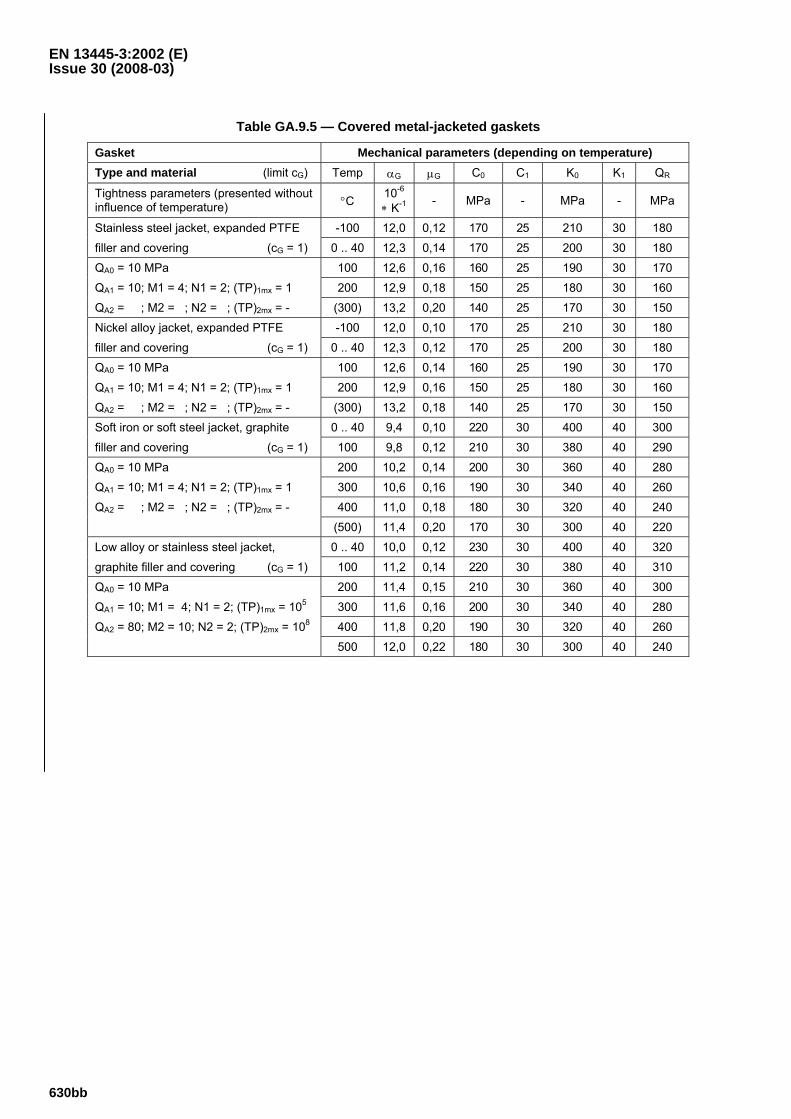
EN 13445-3:2002 (E) Issue 30 (2008-03)
630bb
Table GA.9.5 — Covered metal-jacketed gaskets
Gasket Mechanical parameters (depending on temperature) Type and material (limit cG) Temp αG μG C0 C1 K0 K1 QR
Tightness parameters (presented without influence of temperature) °C 10-6
∗ K-1 - MPa - MPa - MPa
Stainless steel jacket, expanded PTFE -100 12,0 0,12 170 25 210 30 180
filler and covering (cG = 1) 0 .. 40 12,3 0,14 170 25 200 30 180
QA0 = 10 MPa 100 12,6 0,16 160 25 190 30 170
QA1 = 10; M1 = 4; N1 = 2; (TP)1mx = 1 200 12,9 0,18 150 25 180 30 160
QA2 = ; M2 = ; N2 = ; (TP)2mx = - (300) 13,2 0,20 140 25 170 30 150
Nickel alloy jacket, expanded PTFE -100 12,0 0,10 170 25 210 30 180
filler and covering (cG = 1) 0 .. 40 12,3 0,12 170 25 200 30 180
QA0 = 10 MPa 100 12,6 0,14 160 25 190 30 170
QA1 = 10; M1 = 4; N1 = 2; (TP)1mx = 1 200 12,9 0,16 150 25 180 30 160
QA2 = ; M2 = ; N2 = ; (TP)2mx = - (300) 13,2 0,18 140 25 170 30 150
Soft iron or soft steel jacket, graphite 0 .. 40 9,4 0,10 220 30 400 40 300
filler and covering (cG = 1) 100 9,8 0,12 210 30 380 40 290
QA0 = 10 MPa 200 10,2 0,14 200 30 360 40 280
QA1 = 10; M1 = 4; N1 = 2; (TP)1mx = 1 300 10,6 0,16 190 30 340 40 260
QA2 = ; M2 = ; N2 = ; (TP)2mx = - 400 11,0 0,18 180 30 320 40 240
(500) 11,4 0,20 170 30 300 40 220
Low alloy or stainless steel jacket, 0 .. 40 10,0 0,12 230 30 400 40 320
graphite filler and covering (cG = 1) 100 11,2 0,14 220 30 380 40 310
QA0 = 10 MPa 200 11,4 0,15 210 30 360 40 300
QA1 = 10; M1 = 4; N1 = 2; (TP)1mx = 105 300 11,6 0,16 200 30 340 40 280
QA2 = 80; M2 = 10; N2 = 2; (TP)2mx = 108 400 11,8 0,20 190 30 320 40 260
500 12,0 0,22 180 30 300 40 240
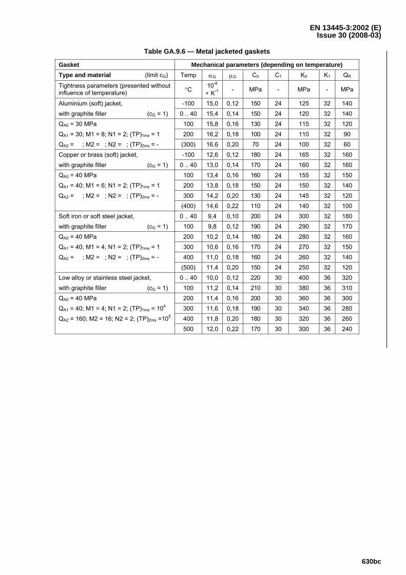
EN 13445-3:2002 (E) Issue 30 (2008-03)
630bc
Table GA.9.6 — Metal jacketed gaskets
Gasket Mechanical parameters (depending on temperature) Type and material (limit cG) Temp αG μG C0 C1 K0 K1 QR
Tightness parameters (presented without influence of temperature) °C 10-6
∗ K-1 - MPa - MPa - MPa
Aluminium (soft) jacket, -100 15,0 0,12 150 24 125 32 140
with graphite filler (cG = 1) 0 .. 40 15,4 0,14 150 24 120 32 140
QA0 = 30 MPa 100 15,8 0,16 130 24 115 32 120
QA1 = 30; M1 = 8; N1 = 2; (TP)1mx = 1 200 16,2 0,18 100 24 110 32 90
QA2 = ; M2 = ; N2 = ; (TP)2mx = - (300) 16,6 0,20 70 24 100 32 60
Copper or brass (soft) jacket, -100 12,6 0,12 180 24 165 32 160
with graphite filler (cG = 1) 0 .. 40 13,0 0,14 170 24 160 32 160
QA0 = 40 MPa 100 13,4 0,16 160 24 155 32 150
QA1 = 40; M1 = 6; N1 = 2; (TP)1mx = 1 200 13,8 0,18 150 24 150 32 140
QA2 = ; M2 = ; N2 = ; (TP)2mx = - 300 14,2 0,20 130 24 145 32 120
(400) 14,6 0,22 110 24 140 32 100
Soft iron or soft steel jacket, 0 .. 40 9,4 0,10 200 24 300 32 180
with graphite filler (cG = 1) 100 9,8 0,12 190 24 290 32 170
QA0 = 40 MPa 200 10,2 0,14 180 24 280 32 160
QA1 = 40; M1 = 4; N1 = 2; (TP)1mx = 1 300 10,6 0,16 170 24 270 32 150
QA2 = ; M2 = ; N2 = ; (TP)2mx = - 400 11,0 0,18 160 24 260 32 140
(500) 11,4 0,20 150 24 250 32 120
Low alloy or stainless steel jacket, 0 .. 40 10,0 0,12 220 30 400 36 320
with graphite filler (cG = 1) 100 11,2 0,14 210 30 380 36 310
QA0 = 40 MPa 200 11,4 0,16 200 30 360 36 300
QA1 = 40; M1 = 4; N1 = 2; (TP)1mx = 104 300 11,6 0,18 190 30 340 36 280
QA2 = 160; M2 = 16; N2 = 2; (TP)2mx =105 400 11,8 0,20 180 30 320 36 260
500 12,0 0,22 170 30 300 36 240
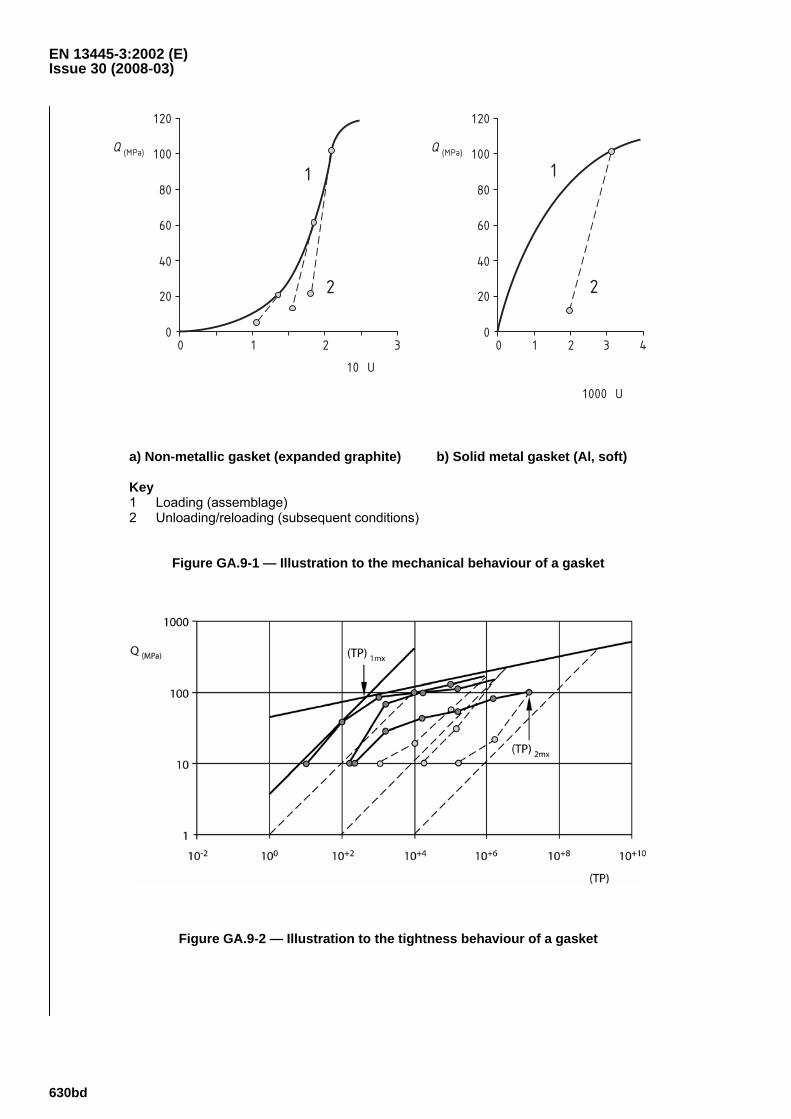
EN 13445-3:2002 (E) Issue 30 (2008-03)
630bd
0 1 2 3
Q (MPa)
0
20
40
60
80
100
120
1
2
10 U
0 1 2 3
Q (MPa)
0
20
40
60
80
100
120
1
2
4
1000 U
a) Non-metallic gasket (expanded graphite) b) Solid metal gasket (Al, soft) Key 1 Loading (assemblage) 2 Unloading/reloading (subsequent conditions)
Figure GA.9-1 — Illustration to the mechanical behaviour of a gasket
Figure GA.9-2 — Illustration to the tightness behaviour of a gasket
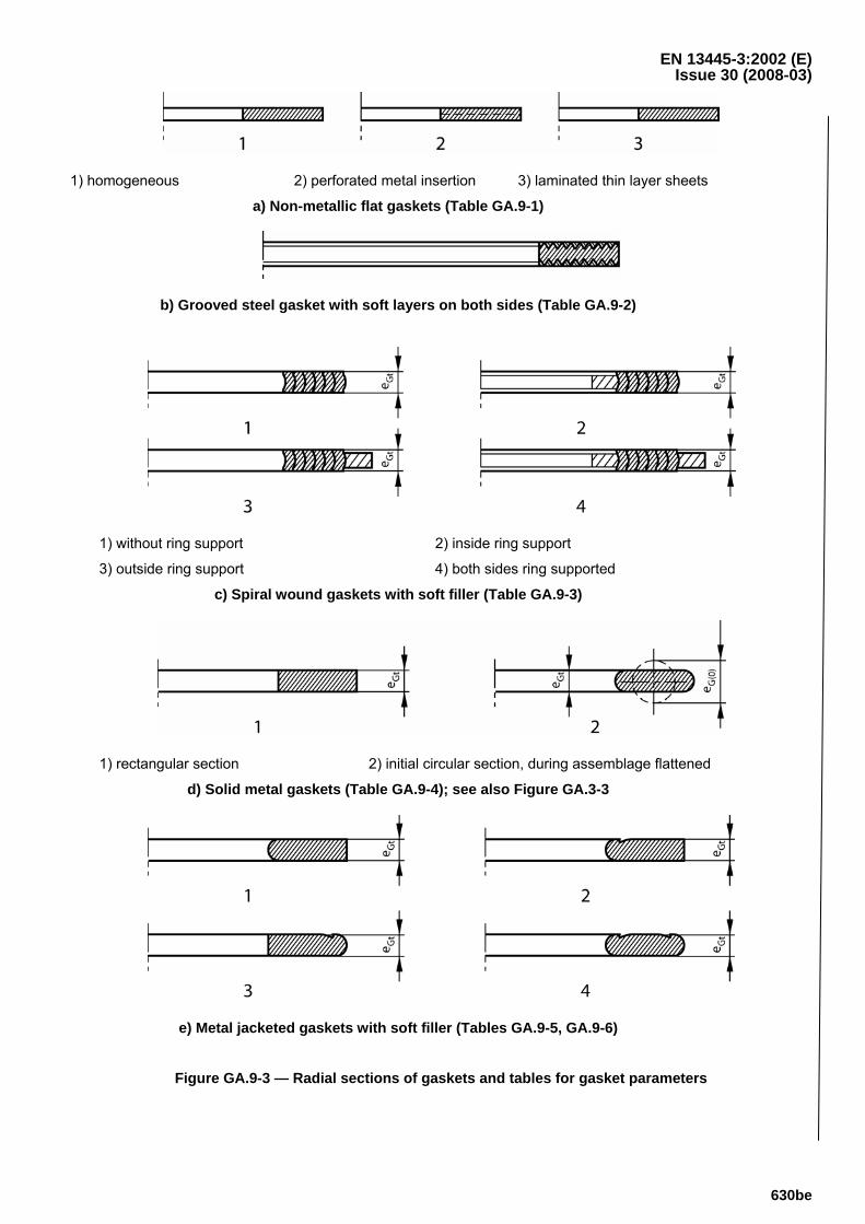
EN 13445-3:2002 (E) Issue 30 (2008-03)
630be
1) homogeneous 2) perforated metal insertion 3) laminated thin layer sheets
a) Non-metallic flat gaskets (Table GA.9-1)
b) Grooved steel gasket with soft layers on both sides (Table GA.9-2)
1) without ring support 2) inside ring support
3) outside ring support 4) both sides ring supported
c) Spiral wound gaskets with soft filler (Table GA.9-3)
1) rectangular section 2) initial circular section, during assemblage flattened
d) Solid metal gaskets (Table GA.9-4); see also Figure GA.3-3
e) Metal jacketed gaskets with soft filler (Tables GA.9-5, GA.9-6)
Figure GA.9-3 — Radial sections of gaskets and tables for gasket parameters

EN 13445-3:2002 (E) Issue 30 (2008-03)
630bf
GA.10 Bibliography
[1] EN 1591-1:2001, Flanges and their joints — Design rules for gasketed circular flange connections — Part 1: Calculation method
[2] ENV 1591-2:2001, Flanges and their joints — Design rules for gasketed circular flange connections — Part 2: Gasket parameters
[3] Wesstrom, D.B.; Bergh, S.E., "Effect of Internal Pressure on Stresses and Strains in Bolted Flange Connections"; Transactions of the ASME, July 1951, pp.553-568
[4] Richtlinienkatalog Festigkeitsberechnungen (RKF), Behälter und Apparate; Teil 1, BR-A13: "Behälter- und Apparateelemente. Flanschverbindungen"; Institut für Chemieanlagen, Dresden 1971; VEB Komplette Chemieanlagen Dresden, 1979
[5] DIN 2505, Berechnung von Flanschverbindungen; Entwurf November 1972
[6] TGL 20360, "Flanschverbindungen. Berechnung auf Festigkeit und Dichtigkeit"; February 1977
[7] TGL 32903/13, "Behälter und Apparate. Festigkeitsberechnung. Flanschverbindungen"; December 1983
[8] Wölfel, J., Räbisch, W.: "Berechnung und Standardisierung von Flanschverbindungen"; Chemische Technik, Leipzig, 1975, S.470-478
[9] Wölfel, J., "Berechnung der Dichtigkeit und Festigkeit von Flanschverbindungen"; Maschinenbautechnik, Berlin, 1985, S.244-247
[10] EN 13555:2004, Flanges and their joints — Gasket parameters and test procedures relevant to the design rules for gasketed circular flange connections
[11] PERL "Pressure Equipment, Reduction of Leak rate: gasket parameters measurement"; Project funded by the European Community under the 'Competitive and Sustainable Growth' Programme (1998-2002)
[12] CR 13642:1999, Flanges and their joints — Design rules for gasketed circular flange connections — Background information