Embed Size (px)
Citation preview

EMV 330 CARD READER
UPGRADE
TDN 07103-10182 July 8, 2014
COPYRIGHT NOTICE© 2014 Triton. All Rights Reserved. TRITON logo is a registered trademark of Triton Systems of Delaware, LLC
Corporate Headquarters21405 B Street
Long Beach, MS 39560Phone: (800) 259-6672
Fax: (228) 575-3101

2
EMV 330 CARD READER UPGRADE
These kits include a Sankyo ICM330 EMV compliant card reader, bezel, and applicable cable for each ATM model. The card reader includes an additional ground wire. Ensure the card reader and cabinet grounds are joined. Use the angle bracket as necessary to make ground connections.
Improper grounding may cause damage to ATM
and/or components.
Document Updates
January 16, 2013 OriginalMarch 5, 2013 ARGO addedJuly 3, 2013 Removed reference to USAugust 28, 2013 Software Dependency updated & RT2/FT5 addedOctober 18, 2013 Added 330 to title, updated pictures & corrected ARGOFebruary 27, 2014 Added Section 5 - 9100/Z180 upgradeJuly 8, 2014 Added 9700 to Section 5 & added 9600 Section 6

3
FIELD CONVERSION PROCEDURE
INTRODUCTION ............................................................................................................................ 4PURPOSE ............................................................................................................................ 4SCOPE ............................................................................................................................ 4SOFTWARE DEPENDENCY ............................................................................................................................ 4UNIT CONFIGURATIONS ............................................................................................................................ 5TOOLS ............................................................................................................................ 5KIT NOTES ............................................................................................................................ 5CARD READER CABLE CONNECTIONS ........................................................................................................ 5SECTION 1 RL16, 2K, ARGO, 5K X2 KIT NUMBER 06200-00347 ................................. 1-1SECTION 2 RL5000 XSCALE KIT NUMBER 06200-00348 ................................ 2-1SECTION 3 TRAVERSE KIT NUMBER 06200-00349 ................................ 3-1SECTION 4 RT2, FT5 KIT NUMBER 06200-00340/00341 ..................... 4-1SECTION 5 9100, Z180, 9700 KIT NUMBER 06200-00352 ................................ 5-1SECTION 6 9600 KIT NUMBER 06200-00252 ................................ 6-1
TABLE OF CONTENTS
4
EMV 330 CARD READER UPGRADE
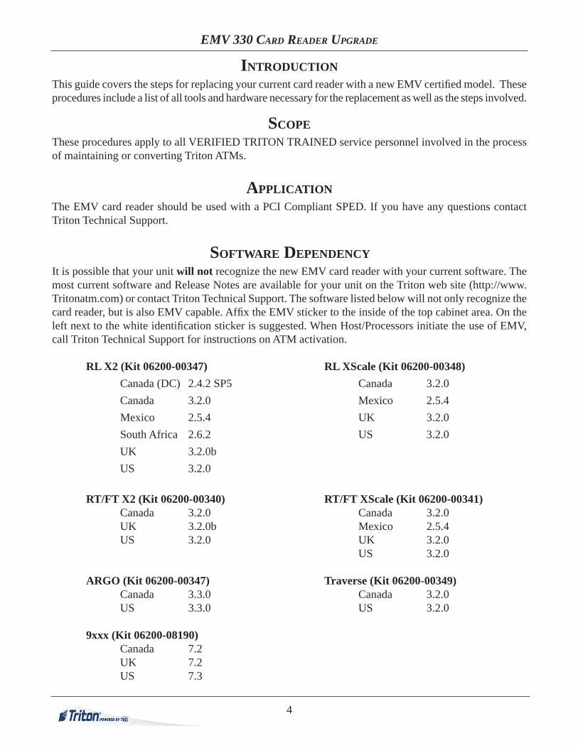
INTRODUCTION This guide covers the steps for replacing your current card reader with a new EMV certifi ed model. These procedures include a list of all tools and hardware necessary for the replacement as well as the steps involved.
SCOPEThese procedures apply to all VERIFIED TRITON TRAINED service personnel involved in the process of maintaining or converting Triton ATMs.
APPLICATIONThe EMV card reader should be used with a PCI Compliant SPED. If you have any questions contact Triton Technical Support.
SOFTWARE DEPENDENCYIt is possible that your unit will not recognize the new EMV card reader with your current software. The most current software and Release Notes are available for your unit on the Triton web site (http://www.Tritonatm.com) or contact Triton Technical Support. The software listed below will not only recognize the card reader, but is also EMV capable. Affi x the EMV sticker to the inside of the top cabinet area. On the left next to the white identifi cation sticker is suggested. When Host/Processors initiate the use of EMV, call Triton Technical Support for instructions on ATM activation.
RL X2 (Kit 06200-00347) RL XScale (Kit 06200-00348) Canada (DC) 2.4.2 SP5 Canada 3.2.0 Canada 3.2.0 Mexico 2.5.4 Mexico 2.5.4 UK 3.2.0 South Africa 2.6.2 US 3.2.0 UK 3.2.0b US 3.2.0
RT/FT X2 (Kit 06200-00340) RT/FT XScale (Kit 06200-00341) Canada 3.2.0 Canada 3.2.0 UK 3.2.0b Mexico 2.5.4 US 3.2.0 UK 3.2.0 US 3.2.0
ARGO (Kit 06200-00347) Traverse (Kit 06200-00349) Canada 3.3.0 Canada 3.2.0 US 3.3.0 US 3.2.0
9xxx (Kit 06200-08190) Canada 7.2 UK 7.2 US 7.3

5
FIELD CONVERSION PROCEDURE
UNIT CONFIGURATIONSDue to production, refurbishment, update, or repair differences, your unit may vary in hardware, or cable color, length, and routing, as compared to the examples given. These instructions are representative of the upgrade for each type of unit. Your units appearance may vary.
TOOLSThe use of magnetic implements may be helpful in the removal and replacement of the card reader hardware.
KITSDue to the versatility of the kits, there may be parts that are not used in your particular unit.
NOTE:
Place the appropriate EMV compliance sticker in the upper part of the cabinet. On the left side below the identifi cation sticker is suggested.
Card Reader Cable Connection:
The black cable connector is “keyed” so will only fi t one way into the grey card reader connector.
Press the connector in fully until the two side clips snap into place.
Ensure the clips are closed, securing the connector.

EMV 330 CARD READER
UPGRADE
RL1613 / RL23XX / ARGO/ RL53XXX2 PLATFORM
KIT 06200-00347
SECTION 1

1-2
EMV 330 CARD READER UPGRADE PROCEDURES
REQUIRED PARTS AND TOOLS
TOOLS REQUIRED #1 & #2 Philips screwdriver with a 6 in. shank, ESD wrist strap with grounding cord
KIT 06200-00347 Field Replacement Kit
Description QtySankyo ICM330 Card Reader Cable ORSerial Card Reader Comms Ribbon Cable
1
Screw #6 x3/8 phillips drive pan plastite 48-2 zinc plate 5Sankyo 330 Card reader w/ software key & Bezel 1Mounting bracket, angled, one 6-32 threaded hole, one 0.165” open hole, 0.062” thick steel, tin plate
1
Screw|#6-32|1/4 Inch|||Pan Phil Head w/Ext Tooth Wash|| ROHS 1
RL1600, RL2k, ARGO, RL5k X2
This kit includes a Sankyo ICM330 EMV compliant card reader, bezel, and ap-plicable cable for each ATM model. The card reader includes an attached ground wire. Ensure the card reader and cabinet grounds are joined.
Improper grounding may cause damage to ATM
and/or components.

1-3
SECTION ONE
3. Refer to the pictures below for illustrative instructions and routing of any cables.
RL1613 REMOVE AND REPLACE PROCEDURES
2. Ensure the old cables are removed from the old card reader and mother/docking board, and the new cables are connected properly to the new card reader and mother/docking board.
1. Refer to the applicable service manual for your unit for steps to remove and replace the card reader. Remove the outer 4 (four) screws only. Ensure you are holding the card reader as you remove the last screw to avoid dropping it.
Before proceeding, follow these steps to remove power from the ATM:Enter Management Functions > System Parameters > Shut Down the Terminal > Enter. When prompted, turn power OFF on the ATMs power supply. Unlock and open the ATM control panel. Turn the power switch to the OFF (0) position. If possible, unplug the ATM power cord at the wall outlet.
Disconnect and remove the card reader to main board cable.
Remove the 4 (four) corner screws retaining the card reader. (upper right hidden)
Install card reader as shown and secure with 4 (four) screws provided. Install and connect the new card reader cable.
Remove screw and attach EMV card reader and cabinet grounds to this point.
Improper grounding may
cause damage to ATM and/or
components.

1-4
EMV 330 CARD READER UPGRADE PROCEDURES
3. Refer to the pictures below for illustrative instructions and routing of any cables.
RL2K X2 & ARGO REMOVE AND REPLACE PROCEDURES
2. Ensure the old cables are removed from the old card reader and mother/docking board, and the new cables are connected properly to the new card reader and mother/docking board.
1. Refer to the applicable service manual for your unit for steps to remove and replace the card reader. Remove the outer 4 (four) screws only. Ensure you are holding the card reader as you remove the last screw to avoid dropping it.
Before proceeding, follow these steps to remove power from the ATM:Enter Management Functions > System Parameters > Shut Down the Terminal > Enter. When prompted, turn power OFF on the ATMs power supply. Unlock and open the ATM control panel. Turn the power switch to the OFF (0) position. If possible, unplug the ATM power cord at the wall outlet.
Disconnect the card reader to docking board cable. The docking board end has a safety clip. RL2k shown.
Remove the 4 (four) corner screws re-taining the card reader.
Under the main board, remove the screw securing the cable clip. Retain the screw.Carefully remove the old card reader to docking board cable.ARGO Carefully remove the old card reader to docking board cable from the clips at the side of the card reader and dock-ing board.
Fold the new card reader cable in half and install under the cable clip.Secure the clip with the screw previously removed. ARGO Route the cable through the clips on the side of the card reader and docking board.

1-5
SECTION ONE
4. Upon completion of the upgrade, perform the card reader test in the diagnostics area of your service manual, and return the unit to service.
Install card reader as shown and secure with 4 (four) screws provided. RL2k shown.
Connect card reader ground cables and original cabinet ground to the ground lug on the card reader. RL2k
Connect the new card reader cable to the card reader and the docking board. RL2k
Connect the new card reader cable to the card reader and the docking board. ARGO
Connect card reader ground cables and original cabinet ground to the ground lug on the card reader. ARGO
Improper grounding may
cause damage to ATM and/or
components.
Improper grounding may
cause damage to ATM and/or
components.

1-6
EMV 330 CARD READER UPGRADE PROCEDURES
3. Refer to the pictures below for illustrative instructions and routing of any cables.
RL5K X2 REMOVE AND REPLACE PROCEDURES
2. Ensure the old cables are removed from the old card reader and mother/docking board, and the new cables are connected properly to the new card reader and mother/docking board.
1. Refer to the applicable service manual for your unit for steps to remove and replace the card reader. Remove the outer 4 (four) screws only. Ensure you are holding the card reader as you remove the last screw to avoid dropping it.
Before proceeding, follow these steps to remove power from the ATM:Enter Management Functions > System Parameters > Shut Down the Terminal > Enter. When prompted, turn power OFF on the ATMs power supply. Unlock and open the ATM control panel. Turn the power switch to the OFF (0) position. If possible, unplug the ATM power cord at the wall outlet.
Disconnect and remove the card reader to dock-ing board cable. The docking board end has a safety clip.
Remove the 4 (four) screws retaining the card reader and any ground cable.
Install card reader as shown and secure with 4 (four) screws provided.
Remove the ground screw and cable retainer, and attach the card reader ground cables using the angle bracket.
Improper grounding may
cause damage to ATM and/or
components.

1-7
SECTION ONE
4. Upon completion of the upgrade, perform the card reader test in the diagnostics area of your service manual, and return the unit to service.
Connect the new cable to the card reader and the docking board.

EMV 330 CARD READER
UPGRADE
RL51XXXSCALE PLATFORM
KIT 06200-00348
SECTION 2

2-2
EMV 330 CARD READER UPGRADE PROCEDURES
REQUIRED PARTS AND TOOLS
TOOLS REQUIRED #1 & #2 Phillips screwdriver with a 6 in. shank, ESD wrist strap with grounding cord
KIT 06200-00348 Field Replacement Kit
Description QtySankyo ICM330 Card Reader Cable, X-scale 1Screw #6 x3/8 phillips drive pan plastite 48-2 zinc plate 4Sankyo 330 Card reader w/ software key & Bezel 1Mounting bracket, angled, one 6-32 threaded hole, one 0.165” open hole, 0.062” thick steel, tin plate
1
Screw|#6-32|1/4 Inch|||Pan Phil Head w/Ext Tooth Wash|| ROHS 1
RL 5k XScale
This kit includes a Sankyo ICM330 EMV compliant card reader, bezel, and ap-plicable cable for each ATM model. The card reader includes an attached ground wire. Ensure the card reader and cabinet grounds are joined. Use the angle bracket as necessary to make ground connections.
Improper grounding may cause damage to ATM
and/or components.

2-3
SECTION TWO
3. Refer to the pictures below for illustrative instructions and routing of any cables.
RL5100 XSCALE REMOVE AND REPLACE PROCEDURES
2. Ensure the old cables are removed from the old card reader and mother/docking board, and the new cables are connected properly to the new card reader and mother/docking board.
1. Refer to the applicable service manual for your unit for steps to remove and replace the card reader. Remove the outer 4 (four) screws only. Ensure you are holding the card reader as you remove the last screw to avoid dropping it.
Before proceeding, follow these steps to remove power from the ATM:Enter Management Functions > System Parameters > Shut Down the Terminal > Enter. When prompted, turn power OFF on the ATMs power supply. Unlock and open the ATM control panel. Turn the power switch to the OFF (0) position. If possible, unplug the ATM power cord at the wall outlet.
Disconnect and remove the card reader to dock-ing board cable.
Remove the 4 (four) corner screws retaining the card reader.
Install card reader as shown and secure with 4 (four) screws provided.Remove the screw retaining the ESD device to
the back of the printer bracket. Loosen the cable retainers along the bottom of the fascia, and re-move the cable and ESD device.

2-4
EMV 330 CARD READER UPGRADE PROCEDURES
4. Upon completion of the upgrade, perform the card reader test in the diagnostics area of your service manual, and return the unit to service.
Remove screw and attach EMV grounds to this point, using the angle bracket.
Connect the new cable to the card reader and docking board. Route and secure as necessary to minimize damage.
Improper grounding may cause damage to ATM and/or components.

EMV 330 CARD READER
UPGRADE TRAVERSE
KIT 06200-00349
SECTION 3

3-2
EMV 330 CARD READER UPGRADE PROCEDURES
REQUIRED PARTS AND TOOLS
TOOLS REQUIRED #1 & #2 philips screwdriver with a 6 inch shank, ESD wrist strap with grounding cord
KIT 06200-00349 Card Reader Upgrade Kit
Description QtySankyo ICM330 card reader cable, Traverse 1Screw #6 x3/8 phillips drive pan plastite 48-2 zinc plate 4Sankyo 330 Card reader w/ software key 1
Traverse
This kit includes a Sankyo ICM330 EMV compliant card reader and applicable cable for each ATM model. The card reader includes an attached ground wire. Ensure the card reader and cabinet grounds are joined.
Improper grounding may cause damage to ATM
and/or components.

3-3
SECTION THREE
3. Refer to the pictures below for illustrative instructions and routing of any cables.
TRAVERSE REMOVE AND REPLACE PROCEDURES
2. Ensure the old cables are removed from the old card reader and mother/docking board, and the new cables are connected properly to the new card reader and mother/docking board.
1. Refer to the applicable service manual for your unit for steps to remove and replace the card reader. Remove the outer 4 (four) screws only. Ensure you are holding the card reader as you remove the last screw to avoid dropping it.
Before proceeding, follow these steps to remove power from the ATM:Enter Management Functions > System Parameters > Shut Down the Terminal > Enter. When prompted, turn power OFF on the ATMs power supply. Unlock and open the ATM control panel. Turn the power switch to the OFF (0) position. If possible, unplug the ATM power cord at the wall outlet.
Disconnect the cable from the existing card reader, and cut the Tye wrap.
Remove the two screws retaining the main board cover, and remove the cover.Disconnect the cable connector from the main board, and remove the cable.
Remove the four small screws retaining the card reader to the fascia. Access to these screws is diffi cult. The top two screws are shown. Two additional screws are on the bottom. Retain the screws for installation of the new card reader.
Attach the new card reader to the fascia using the screws removed in previous step. The card reader will have the circuit board on top. Two left screws shown. Two additional screws on the right side.

3-4
EMV 330 CARD READER UPGRADE PROCEDURES
4. Upon completion of the upgrade, perform the card reader test in the diagnostics area of your service manual, and return the unit to service.
Connect the cable to the Card reader. Route the cable as shown, behind the dis-play/main board bracket, and up through the hole to the main board. Secure with the cable clamp. Replace the main board cover, and secure with the two screws.
Remove ground screw from corner of display bracket and attach card reader ground cables to cabinet grounds.
Improper grounding may cause damage to ATM and/or components.

EMV 330 CARD READER
UPGRADE
RT2/FT5X2 & XSCALE PLATFORM
KIT 06200-00340 & 06200-00341
SECTION 4

4-2
EMV 330 CARD READER UPGRADE PROCEDURES
TOOLS REQUIRED#2 Phillips screwdriver with a 6 inch shank
(Magnetic recommended) ESD wrist strap with grounding cord
KIT P/N: 06200-00340 SANKYO ICM330 DIP EMV CARD READER UPGRADE
X2
PARTS SUPPLIED
DESCRIPTION QUANTITY
Sankyo 330 EMV Card Reader w/ Software Key 1
Serial Card Reader Comms Ribbon Cable 1
Screw | 4mm x 12mm Self Tapping | Plastite | PH | Pan Head 4
Triton EMV Kernel 1
KIT P/N: 06200-00341SANKYO ICM330 DIP EMV CARD READER UPGRADE
XSCALE
PARTS SUPPLIED
DESCRIPTION QUANTITY
Sankyo 330 EMV Card Reader w/ Software Key 1
Sankyo ICM330 Card Reader Cable | XScale 1
Screw | 4mm x 12mm Self Tapping | Plastite | PH | Pan Head 4
Triton EMV Kernel 1
NOTE: This kit includes a Sankyo ICM330 EMV compliant card reader, bezel and applicable cable for each ATM model. The card reader includes an attached ground wire. Ensure the card reader and cabinet ground wires are joined. Use the angle bracket as necessary to make ground connections.
Improper grounding may cause damage to ATM
and/or components.

4-3
SECTION FOUR
REMOVING THE CARD READER ASSEMBLY FROM THE UNIT
The Card Reader Assembly is located on the control panel.Tools: 1 - #2 Phillips screwdriver 1 - ESD wrist strap with grounding cord
To remove the card reader assembly, complete the following procedure:1. Put the ESD wrist strap on and attach the cord to the ground.2. Perform a proper shut down of the unit.3. Unlock and open the upper portion of the cabinet. Turn the power switch on the power supply OFF.4. Using a #2 Phillips screwdriver, remove the screw and two ground wires on the side of the card
reader cover. Set the screw aside for reinstall.
5. Rotate the card reader cover open and remove the top portion. Set aside.

4-4
EMV 330 CARD READER UPGRADE PROCEDURES
REMOVING THE CARD READER ASSEMBLY FROM THE UNIT CONT...
6. Pop the bushing out of the bracket to release the card reader cable. Set the bushing aside for rein-stall. Unplug the cable from the card reader and from the main board.
7. While holding the card reader and bracket, remove the four screws securing the assembly to the control panel. Set the bracket aside for reinstall.

4-5
SECTION FOUR
The Card Reader Assembly is located on the control panel.Tools: 1 - #2 Phillips screwdriver 1 - ESD wrist strap with grounding cord
To install the EMV card reader assembly, complete the following procedure:1. Put the ESD wrist strap on and attach the cord to the ground.2. Set the EMV card reader in place and set the cover in place over the reader.3. While holding the card reader and bracket in place, secure the parts to the control panel with the four
screws previously removed.
4. Plug the new card reader cable into the top of the card reader (X2 ribbon cable shown below).
INSTALLING THE EMV CARD READER ASSEMBLY INTO THE UNIT

4-6
EMV 330 CARD READER UPGRADE PROCEDURES
INSTALLING THE EMV CARD READER ASSEMBLY INTO THE UNIT CONT...
5. Attach the grommet previously removed to both the card reader ground wire and the card reader cable. Insert the grommet into the bracket hole.
6. Reinstall the card reader cover by inserting the two tabs into the two notches and rotating into the closed position.
7. Plug the card reader cable into the main board.

4-7
SECTION FOUR
INSTALLING THE EMV CARD READER ASSEMBLY INTO THE UNIT CONT...
8. Secure the card reader ground wire, audio ground wire and the main ground wire to the side of the card reader cover with the screw previously removed. Ensure the wires are in the correct order:
Card reader bracket > Card reader ground > Audio ground > Control panel ground > Screw
9. Unclip the cable clip closest to the card reader bracket. Route the card reader cable through the clip, loop and route it back. Snap the cable clip closed.
10. Upon completion of the upgrade, restore power to the unit. Perform the card reader test in the diagnostics area of your service manual then return the unit to service.
Improper grounding may
cause damage to ATM and/or
components.

EMV 330 CARD READER
UPGRADE
8100/9100/9700
KIT 06200-00352
SECTION 5

5-2
EMV 330 CARD READER UPGRADE PROCEDURES
TOOLS REQUIRED
#2 Phillips screwdriver with a 8 inch shank (Magnetic recommended)
ESD wrist strap with grounding cordSide cut pliers
KIT P/N: 06200-00352 SANKYO ICM330 CARD READER UPGRADE FOR 8100/9100/9700
PARTS SUPPLIED
DESCRIPTION QUANTITY
Sankyo 330 EMV Card Reader w/ Software Key & RL/ARGO/9100 Bezel 1
Sankyo ICM330 Card Reader Cable Z180 36” 1
Screw #6 x 3/8 Phillips Drive Pan Plastite 48-2 Zinc Plate 4
6 Inch Ty Wrap 2
CreditCall EMV License 1
NOTE: This kit includes a Sankyo ICM330 EMV compliant card reader, bezel and applicable cable for each ATM model. The card reader includes an attached ground wire. Ensure the card reader and cabinet ground wires are joined.
Improper grounding may cause damage to ATM
and/or components.
CONTENTS
8100/9100REMOVING THE MAGTEK I-65 CARD READER ASSEMBLY ...............................................PAGE 5-3REMOVING THE TRACK 1-2 CARD READER ASSEMBLY ...................................................PAGE 5-6INSTALLING THE SANKYO EMV330 CARD READER ASSEMBLY ......................................PAGE 5-8
9700REMOVING THE OLD CARD READER ASSEMBLY ...........................................................PAGE 5-11INSTALLING THE SANKYO EMV330 CARD READER ASSEMBLY ....................................PAGE 5-13

5-3
SECTION FIVE
8100 / 9100REMOVING THE MAGTEK I-65 CARD READER ASSEMBLY
The Card Reader Assembly is located on the control panel.Tools: 1 - #2 Phillips screwdriver 1 - ESD wrist strap with grounding cord 1 - Side cut pliers
To remove the card reader assembly, complete the following procedure:1. Put the ESD wrist strap on and attach the cord to the ground.2. Unlock and open the upper portion of the cabinet. 3. Turn the power switch on the power supply OFF.4. Unplug the communication cable from the card reader.
5. Remove the screw securing the two card reader ground wires. Reinstall the screw to secure the mainboard cover.

5-4
EMV 330 CARD READER UPGRADE PROCEDURES
REMOVING THE MAGTEK I-65 CARD READER ASSEMBLY CONT...
6. While holding the card reader bezel from underneath, remove the four screws securing the card reader. Remove the card reader from the control panel. Discard screws and card reader.
7. Cut the TY Wraps holding the card reader cable and the printer power cable to the mainboard cover.

5-5
SECTION FIVE
8. Unplug the card reader cable from the back of the mainboard.
9. Remove the screw holding the card reader cable ferrite box to the post. Remove the post from the mainboard cover. Discard the post and cable. Reinstall the screw into the mainboard cover to secure the two covers together.
REMOVING THE MAGTEK I-65 CARD READER ASSEMBLY CONT...

5-6
EMV 330 CARD READER UPGRADE PROCEDURES
REMOVING THE TRACK 1-2 CARD READER ASSEMBLYThe Card Reader Assembly is located on the control panel.Tools: 1 - #2 Phillips screwdriver 1 - ESD wrist strap with grounding cord 1 - Side cut pliers
To remove the card reader assembly, complete the following procedure:1. Put the ESD wrist strap on and attach the cord to the ground.2. Unlock and open the upper portion of the cabinet.3. Turn the power switch on the power supply OFF.4. Unplug the communication cable from the front of the mainboard.
5. While holding the card reader bezel from underneath, remove the four screws securing the card reader. Remove the card reader, with the communication cable still attached, from the control panel. Discard screws, card reader and attached cable.

5-7
SECTION FIVE
6. Cut the TY Wraps holding the printer power cable to the mainboard cover.
REMOVING THE TRACK 1-2 CARD READER ASSEMBLY CONT...

5-8
EMV 330 CARD READER UPGRADE PROCEDURES
The Card Reader Assembly is located on the control panel.Tools: 1 - #2 Phillips screwdriver 1 - ESD wrist strap with grounding cord 1 - Side cut pliers
To install the card reader assembly, complete the following procedure:1. Put the ESD wrist strap on and attach the cord to the ground.2. Unlock and open the upper portion of the cabinet. 3. Turn the power switch on the power supply OFF.4. Insert the EMV card reader into the control panel from underneath. Ensure the card reader slot
extends up and down as shown in the picture below. Line up the predrilled holes in the card reader bezel with the holes in the control panel. Secure the card reader in place with the 4 new screws supplied in the upgrade kit.
5. Remove the rear right printer bracket screw. Reinstall the screw securing the EMV card reader ground wire (and the unit main ground wire if applicable).
Improper grounding may
cause damage to ATM and/or
components.
INSTALLING THE SANKYO EMV330 CARD READER ASSEMBLY
Front view of card reader

5-9
SECTION FIVE
6. Obtain the card reader cable. Examine the cable end and the cable port on the card reader. Ensuring the locking tabs are out, plug the cable into the card reader lining up the tab on the cable with the notch in the port. The tabs will close as the cable is inserted into the port. Ensure the tabs click into the locking position.
7. Plug the card reader cable into port J2 in the back of the mainboard.
INSTALLING THE SANKYO EMV330 CARD READER ASSEMBLY CONT...

5-10
EMV 330 CARD READER UPGRADE PROCEDURES
8. Route the EMV card reader cable and the printer power cable along the side of the mainboard cover as shown. TY Wrap the two cables together to the mainboard cover. Cut off excess TY Wrap.
9. Loop the excess card reader cable onto itself neatly and route the cable through cable clip as shown.
INSTALLING THE SANKYO EMV330 CARD READER ASSEMBLY CONT...

5-11
SECTION FIVE
1. Put the ESD wrist strap on and attach the cord to the ground.
2. Unlock and open the upper portion of the cabinet.
3. Flip the switch on the power supply to the OFF (O) position.
4. Unplug the card reader data cable from the docking board.
NOTE: the card reader cable may be plugged into J15 “Card Reader” or J13 :Port 3” depending on the model card reader being removed.
9700Removing the old Card Reader
5. If necessary, remove the screw securing the ferrite box to the control panel. Remove the brass post. Discard the screw and post.

5-12
EMV 330 CARD READER UPGRADE PROCEDURES
6. While holding the card reader from the front of the control panel, remove the 4 screws that secure it in place. Remove the card reader and card reader data cable.

5-13
SECTION FIVE
5. Remove the screw securing the unit ground wire to the control panel. Install the card reader ground cable onto the screw and reinstall the screw as shown.
View from Front of Unit(Triton logo correctly oriented)
Installing the Sankyo EMV 330 Card Reader1. Put the ESD wrist strap on and attach the cord to the ground.2. Unlock and open the upper portion of the cabinet.3. Flip the switch on the power supply to the OFF (O) position.4. Insert the EMV card reader from the front of the unit. Secure the card reader in place with the 4 screws
supplied.

5-14
EMV 330 CARD READER UPGRADE PROCEDURES
6. Obtain the EMV card reader data cable. Ensure the cable locking tabs on the card reader are in the unlocked position (out). Plug the cable into the card reader. As the cable is inserted into the port, the locking tabs will close over the cable securing it in place.
7. Plug the other end of the card reader cable into J13 Port 3 of the docking board.

5-15
SECTION FIVE
8. Set the J13 jumper +12v.
9. Loop the card reader cable back on itself to condense the length of the cable. TY Wrap the cable in two spots as shown. Cut off excess TY Wraps.

EMV 330 CARD READER
UPGRADE
9600
KIT 06200-00252
SECTION 6

6-2
EMV 330 CARD READER UPGRADE PROCEDURES
TOOLS REQUIRED
2 x #2 Phillips screwdriver (stubby and standard)(Magnetic recommended)
ESD wrist strap with grounding cordSmall needle nose pliers7/16 open end wrench
KIT P/N: 06200-00252 EMV ICM330 CARD READER UPGRADE KIT FOR 9600
PARTS SUPPLIED
DESCRIPTION QUANTITY
Sankyo 330 EMV Card Reader 1
Sankyo ICM330 Card Reader Cable 1
8 inch Braid Ground Cable 2
Screw #6 x 3/8 Phillips Drive Pan Plastite 48-2 Zinc Plate 4
#8 x 32 - 3/8 Long Standoff 1
Threaded #8 - 32 Thread Snap-in Insert 1
#8 x 32 - 3/8 Long Screw 1
NOTE: This kit includes a Sankyo ICM330 EMV compliant card reader, bezel and applicable cable for each ATM model. The card reader includes an attached ground wire. Ensure the card reader and cabinet ground wires are joined.
Improper grounding may cause damage to ATM
and/or components.

6-3
SECTION SIX
** IMPORTANT **If the unit intended for upgrade has a Quad-Port Module
with one of the following part numbers, the module is NOT compatible with the EMV upgrade and must be upgraded.
09600-0203009600-01013
These boards do not have a +12v port available.

6-4
EMV 330 CARD READER UPGRADE PROCEDURES
1. Put the ESD wrist strap on and attach the cord to the ground.2. Unlock and open the upper portion of the cabinet.3. Flip the switch on the power supply to the OFF (O) position.4. Unplug the card reader data cable from the PCI SPED Adapter Board.
Removing the old Card Reader
5. While holding the card reader from the front of the control panel, remove the 4 screws that secure it in place. Remove the card reader and card reader data cable.

6-5
SECTION SIX
5. Remove the screw securing the unit ground wire to the control panel. Discard the screw.
View from Front of Unit(Triton logo correctly oriented)
Installing the Sankyo EMV 330 Card Reader1. Put the ESD wrist strap on and attach the cord to the ground.2. Unlock and open the upper portion of the cabinet.3. Flip the switch on the power supply to the OFF (O) position.4. Insert the EMV card reader from the front of the unit. Secure the card reader in place with the 4 screws
supplied.

6-6
EMV 330 CARD READER UPGRADE PROCEDURES
6. Obtain the EMV card reader data cable. Ensure the cable locking tabs on the card reader are in the unlocked position (out). Plug the cable into the card reader. As the cable is inserted into the port, the locking tabs will close over the cable securing it in place.
7. Open the four cable clips (yellow arrows). Route the card reader cable (red arrows) under the printer power cable (green arrow) and through the four cable clips as shown. Close the clips to secure the cables.

6-7
SECTION SIX
8. Plug the EMV card reader cable into the module. If the module is a Multi-Function board with part numbers 09110-00414 or 09110-01414, plug the card reader cable into the port labeled “Reader”.
If the module is a Quad-Port module with part numbers 09600-00020 or 09600-00044, set the JP5 jumper to “Aux (2)” position and the JP3 jumper to the “+12v” position. Plug the card reader cable into the “Serial 3”port.
If the module is a Tri-Port module with part number 09110-00235, set the J4 jumper to the “+12v” position. Plug the card reader cable into the “Serial 3” port.
6-8
EMV 330 CARD READER UPGRADE PROCEDURES
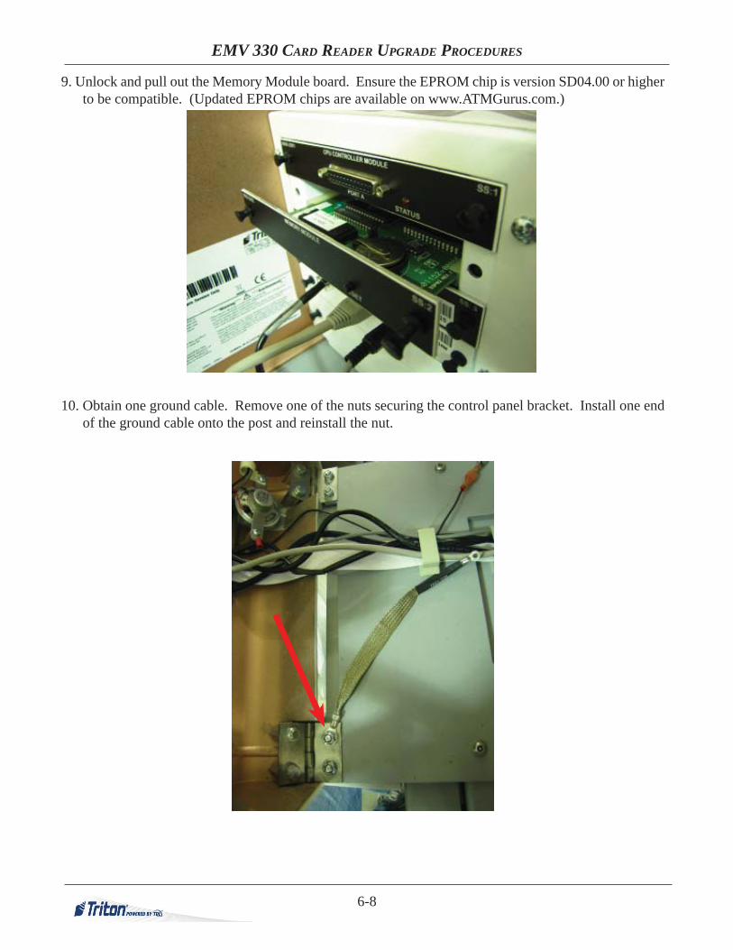
9. Unlock and pull out the Memory Module board. Ensure the EPROM chip is version SD04.00 or higher to be compatible. (Updated EPROM chips are available on www.ATMGurus.com.)
10. Obtain one ground cable. Remove one of the nuts securing the control panel bracket. Install one end of the ground cable onto the post and reinstall the nut.
6-9
SECTION SIX
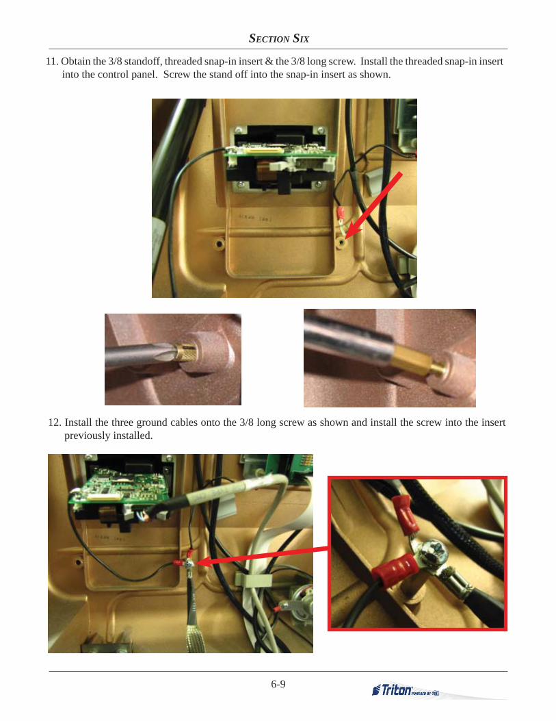
11. Obtain the 3/8 standoff, threaded snap-in insert & the 3/8 long screw. Install the threaded snap-in insert into the control panel. Screw the stand off into the snap-in insert as shown.
12. Install the three ground cables onto the 3/8 long screw as shown and install the screw into the insert previously installed.

6-10
EMV 330 CARD READER UPGRADE PROCEDURES 13. Obtain the second ground cable. Remove the bolt and washer along the rear wall in the rear right
corner. Install the ground wire under the washer and reinstall the bolt into the cabinet. Remove the screw from the card cage and secure the other end of the ground cable as shown.
14. With the unit’s power still OFF, check the resistance of the grounded points. Place one ohmmeter probe on the screw securing the ground cable to the card cage and place the other probe on the screw securing the unit’s three ground cables to the control panel. The resistance should measure less than 1 ohm.