Embed Size (px)
Citation preview

EMSA Workshop, Zurich 2012
Power supplies for induction motor testing and measurements
Andrew Baghurst, CalTest, Port Elliot, South Australia

Variable mains-derived supply
(Only one phase shown – three required)

Coarse-fine mains voltage derived supply
(Only one phase shown – three required)

Induction regulator
Output voltage V2 (line-to-neutral) is the phasor sum of V1 and E2
The phase angle between V1 and E2 is adjusted by rotation of the secondary winding with respect to the primary

Induction regulator phasor diagram
(Diagram shows one phase only)

Brushless alternator
Voltage controlled via exciter field: highly stable if an automatic voltage regulator (AVR) is used Frequency accuracy and stability very high if driven by a variable speed drive with encoder feedback

Brushless alternator with exciter rotor and rotating rectifier
(Full main rotor excitation can only be achieved at or near rated speed)

Slip-ring alternator
Voltage controlled via exciter field: highly stable if an automatic voltage regulator (AVR) is used Frequency accuracy and stability very high if driven by a variable speed drive with encoder feedback Now has variable frequency capability, with V/f constant, and can start very large motors under test

250 kVA alternator exciter

250 kVA alternator slip-rings

Rotating machine dynamometer system with regeneration – Mains supplies losses only

Circuit diagram
PWM Waveforms

Typical commercial sine-EMC filter (EPCOS)

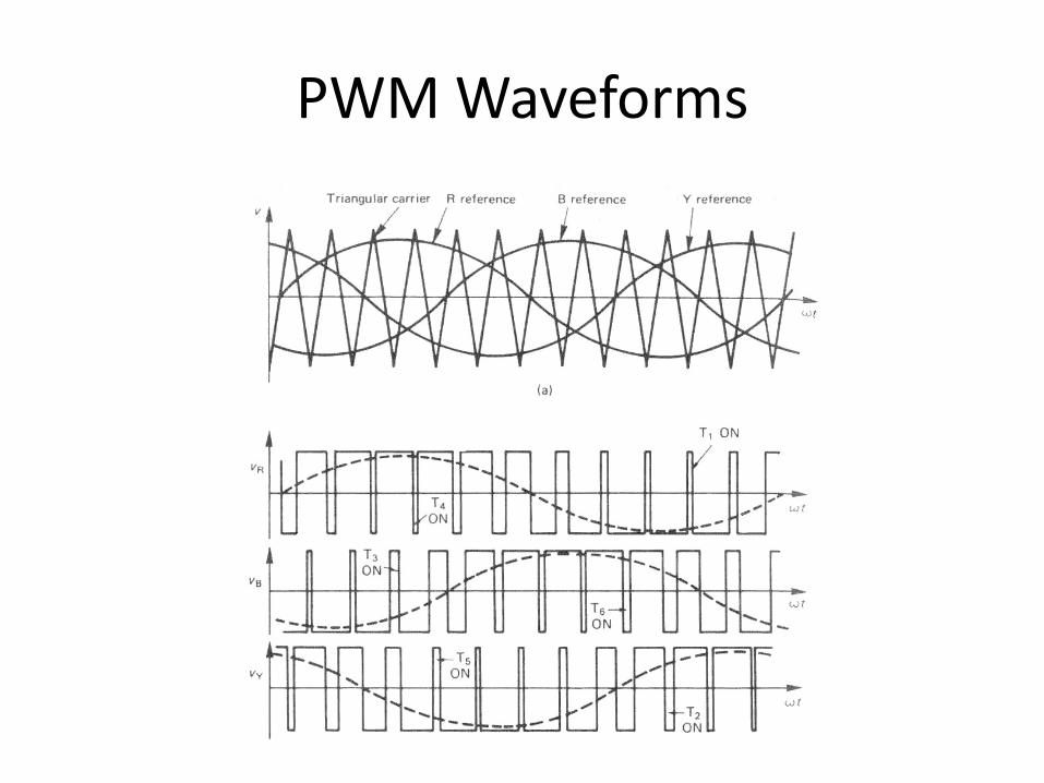
VSD with single-stage L-C-R ‘sine-filter’ (Note the filter return to the d.c. link capacitive divider)

VSD with two-stage L-C-R ‘sine-filter’ (Note the filter return to the d.c. link capacitive divider)

VSD with two-stage L-C-R ‘sine-filter’ and ‘carrier’-frequency parallel-resonant traps
High purity sine filter

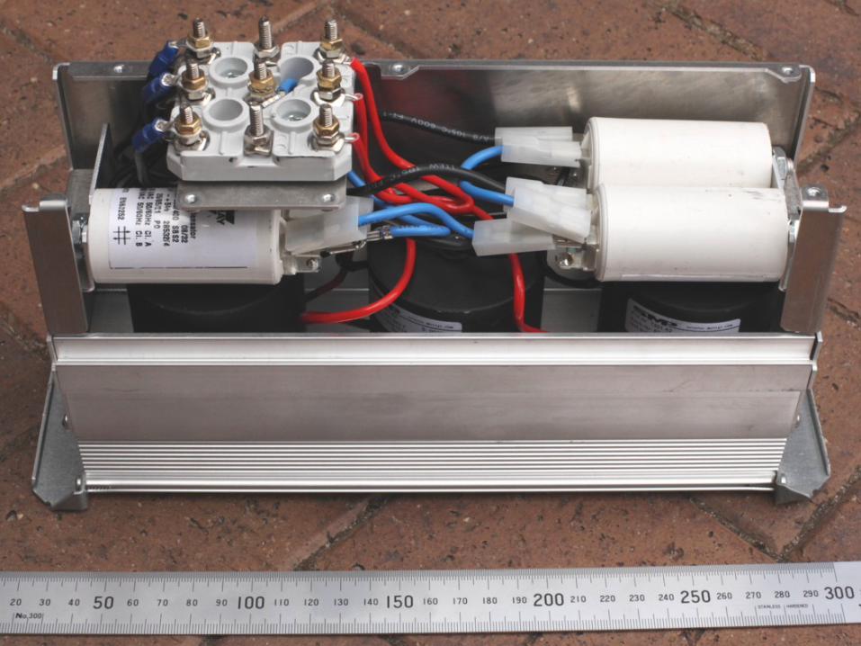

Post-sine-filter adjustable voltage boost


M1: Motor under test M2: Loading motor
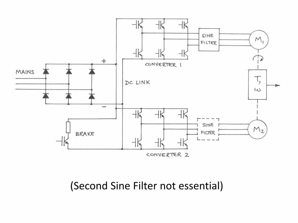
(Second Sine Filter not essential)

M1: Motor under test M2: Loading motor Power circulates clockwise – mains supply losses

To decelerate and stop either machine rapidly, energy can be dumped into the brake resistor

Is this the future for rotating machine testing laboratories?


![INDEX [euro-group.it]Slinky lines 1.950 Employees EuroGroup is always with you. ... Starter motor Alternator stator core Electric Power Steering motor (PSM) Window lift motor ... and](https://img.pdfslide.us/doc/110x75/5e927a7bdc331f000f4f1318/index-euro-groupit-slinky-lines-1950-employees-eurogroup-is-always-with-you.jpg)