Embed Size (px)
Citation preview
EMS User ManualV1.0

Contents
EPON EQUIPMENT MANAGEMENT .............................................................................................................. 2
1.1. CHASSIS MANAGEMENT ............................................................................................................................. 2
1.2. SWITCH CONTROL BOARD MANAGEMENT ............................................................................................... 3
1.2.1. BASIC INFORMATION .............................................................................................................................. 4
1.2.2. IN-BAND IP PORT MANAGEMENT ......................................................................................................... 4
1.2.3. TRUNK MANAGEMENT ........................................................................................................................... 4
1.2.4. QINQ ................................................................................................................................................... 5
1.2.5. VLAN MANAGEMENT ......................................................................................................................... 6
1.2.6. SWITCH MODE CONFIGURE ................................................................................................................... 7
1.2.7. RSTP(RAPID SPANNING TREE PROTOCOL)............................................................................................ 8
1.2.8. ONU AUTHORIZATION ......................................................................................................................... 8
1.2.9. UPLINK PORTS PARAMETERS ................................................................................................................ 9
1.2.10. UPLINK PORT STATUS .......................................................................................................................... 10
1.3. PON CARD MANAGEMENT...................................................................................................................... 10
1.3.1. BASIC INFORMATION ............................................................................................................................ 11
1.3.2. PON PORT INFORMATION ................................................................................................................... 11
1.3.3. ONU LIST .......................................................................................................................................... 13
1.3.4. BRIDGE CONFIGURATION ................................................................................................................... 14
1.3.5. DBA (DYNAMIC BANDWIDTH ALLOCATION) MANAGEMENT ............................................................. 15
1.3.6. AGGREGATE BANDWIDTH CONFIGURATION ....................................................................................... 16
1.3.7. ACL (ACCESS CONTROL LIST) MANAGEMENT.................................................................................... 16
1.3.8. PRIORITY MAPPING ............................................................................................................................ 18
1.3.9. LLID BRIDGE MODE .......................................................................................................................... 18
1.3.10. SLA (SERVICE LEVEL AGREEMENT) ................................................................................................... 19
1.3.11. MAC ADDRESS MANAGEMENT .......................................................................................................... 20
1.3.12. BLOCKED LINK MANAGEMENT ............................................................................................................ 20
1.4. ONU MANAGEMENT ................................................................................................................................ 21
1.4.1. ONU PORT MANAGEMENT ................................................................................................................. 22
1.4.2. ONU BRIDGE MODE CONFIGURATION ............................................................................................... 23
1.4.3. MAC ADDRESS MANAGEMENT .......................................................................................................... 23
1.4.4. ONU LOOP BACK TEST ...................................................................................................................... 24
1.4.5. ONU IGMP SNOOPING ...................................................................................................................... 25
1.4.6. ONU’S ACL CONFIGURATION ............................................................................................................ 26
1.4.7. ONU VLAN CONFIGURATION ........................................................................................................... 27
1.4.8. ONU QUEUE MANAGEMENT .............................................................................................................. 28
1.4.9. ONU PORT FLOW CONTROL/SHAPE MANAGEMENT............................................................................ 29
1.5. EPON UPGRADING................................................................................................................................. 29
1.5.1. UPLOAD FILES .................................................................................................................................... 29
1.5.2. DOWNLOAD FILES ................................................................................................................................ 32
EMS Us e r Manual-EPON N e twork Manag e m e nt
EPON Equipment Management
1.1.Chassis Management
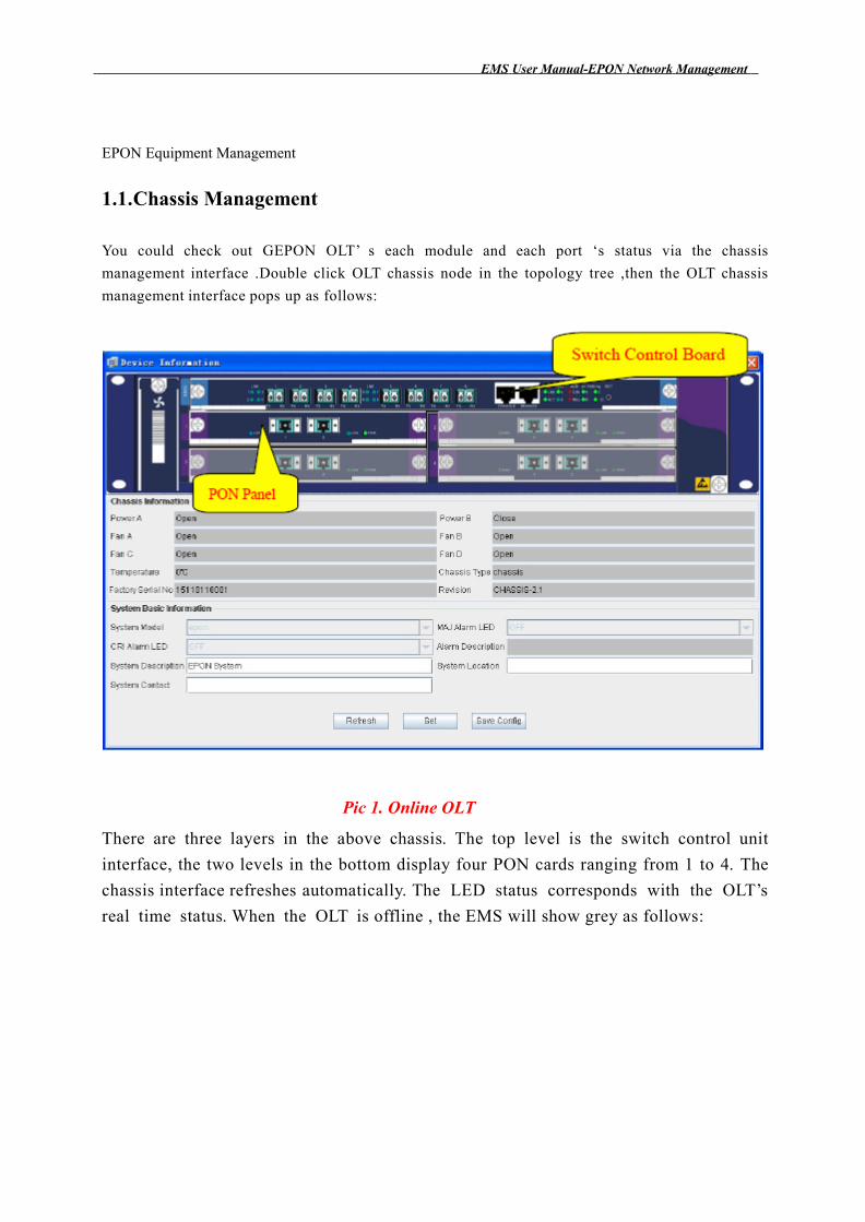
You could check out GEPON OLT’ s each module and each port ‘s status via the chassis
management interface .Double click OLT chassis node in the topology tree ,then the OLT chassis
management interface pops up as follows:
Pic 1. Online OLT
There are three layers in the above chassis. The top level is the switch control unit
interface, the two levels in the bottom display four PON cards ranging from 1 to 4. The
chassis interface refreshes automatically. The LED status corresponds with the OLT’s
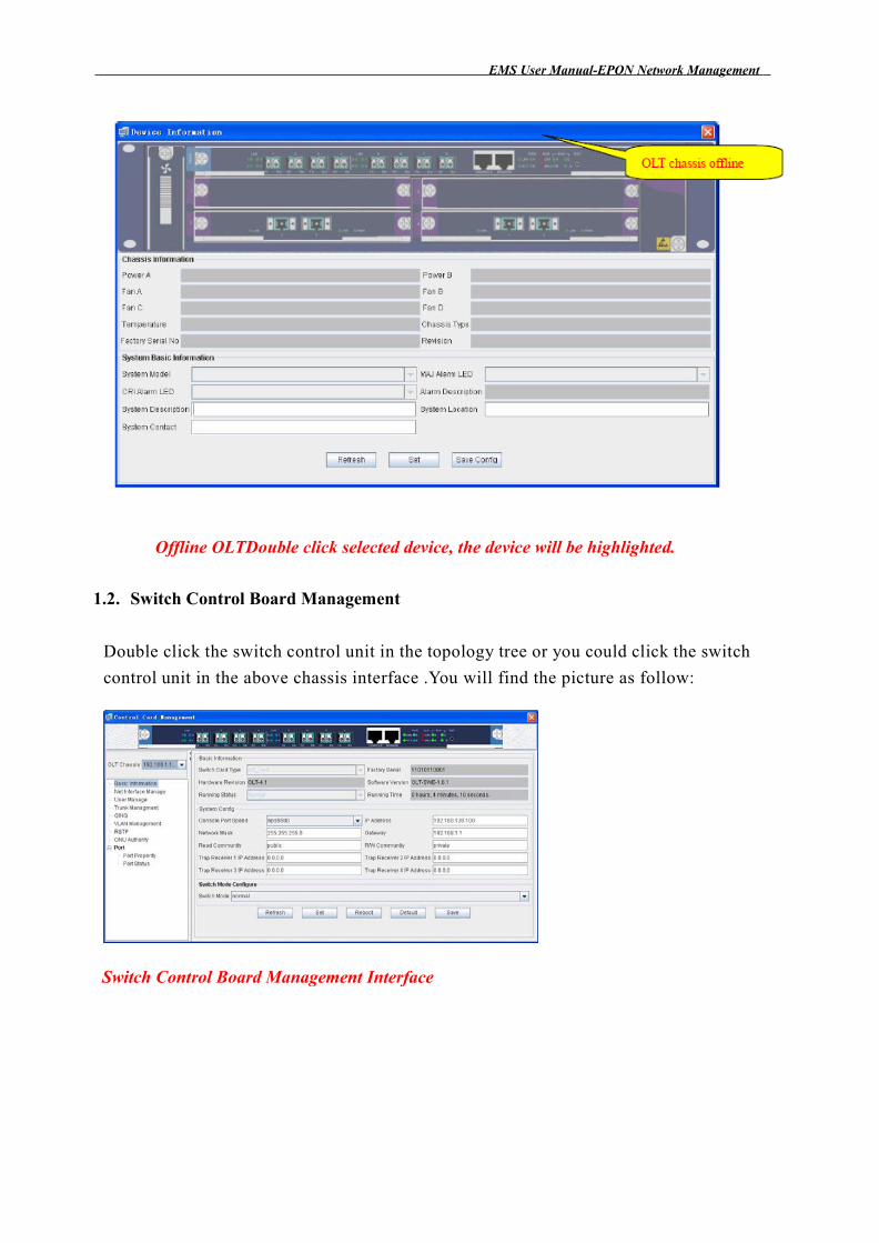
real time status. When the OLT is offline , the EMS will show grey as follows:
EMS Us e r Manual-EPON N e twork Manag e m e nt
Offline OLTDouble click selected device, the device will be highlighted.
1.2. Switch Control Board Management
Double click the switch control unit in the topology tree or you could click the switch
control unit in the above chassis interface .You will find the picture as follow:
Switch Control Board Management Interface
EMS Us e r Manual-EPON N e twork Manag e m e nt
1.2.1. Basic Information
EMS displays switch control board’s basic information .Users could modify the
networking configuration, such as IP address, network mask and gateway, etc.
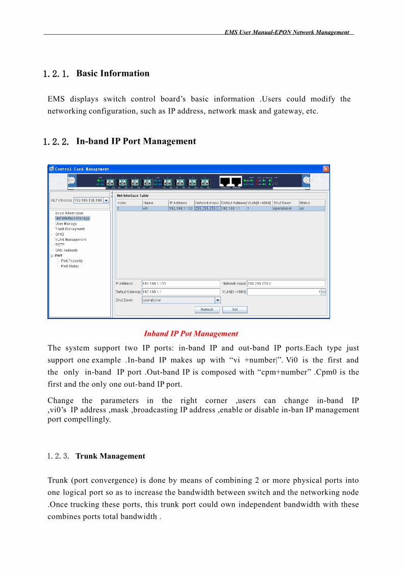
1.2.2. In-band IP Port Management
Inband IP Pot Management
The system support two IP ports: in-band IP and out-band IP ports.Each type just
support one example .In-band IP makes up with “vi +number|”. Vi0 is the first and
the only in-band IP port .Out-band IP is composed with “cpm+number” .Cpm0 is the
first and the only one out-band IP port.
Change the parameters in the right corner ,users can change in-band IP ,vi0’s IP address ,mask ,broadcasting IP address ,enable or disable in-ban IP management port compellingly.
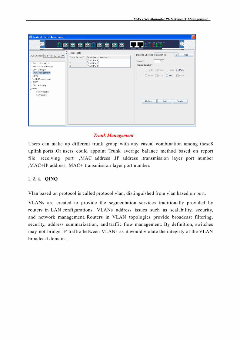
1.2.3. Trunk Management
Trunk (port convergence) is done by means of combining 2 or more physical ports into
one logical port so as to increase the bandwidth between switch and the networking node
.Once trucking these ports, this trunk port could own independent bandwidth with these
combines ports total bandwidth .
EMS Us e r Manual-EPON N e twork Manag e m e nt
Trunk Management
Users can make up different trunk group with any casual combination among these8
uplink ports .Or users could appoint Trunk average balance method based on report
file receiving port ,MAC address ,IP address ,transmission layer port number
,MAC+IP address, MAC+ transmission layer port number.
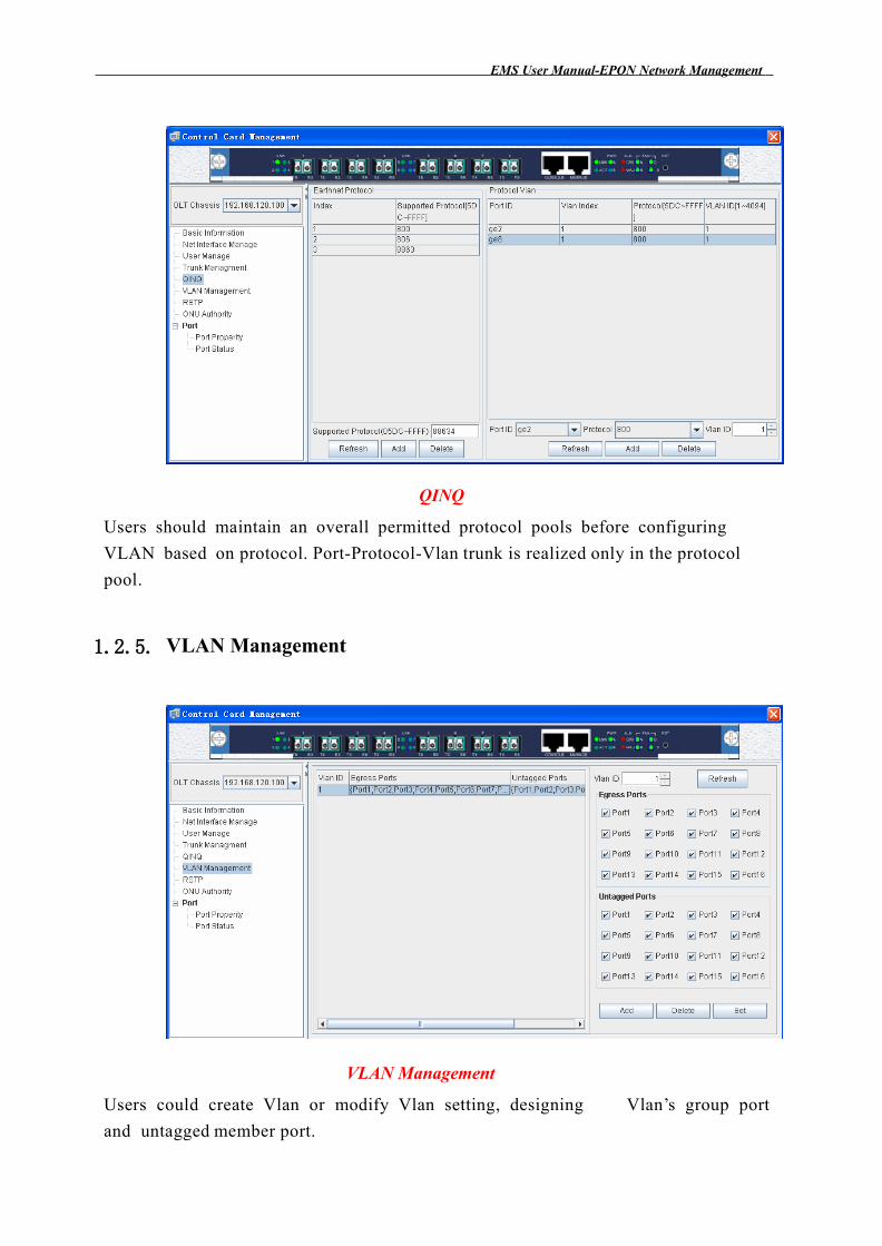
1.2.4. QINQ
Vlan based on protocol is called protocol vlan, distinguished from vlan based on port.
VLANs are created to provide the segmentation services traditionally provided by
routers in LAN configurations. VLANs address issues such as scalability, security,
and network management. Routers in VLAN topologies provide broadcast filtering,
security, address summarization, and traffic flow management. By definition, switches
may not bridge IP traffic between VLANs as it would violate the integrity of the VLAN
broadcast domain.
EMS Us e r Manual-EPON N e twork Manag e m e nt
QINQ
Users should maintain an overall permitted protocol pools before configuring
VLAN based on protocol. Port-Protocol-Vlan trunk is realized only in the protocol
pool.
1.2.5. VLAN Management
VLAN Management
Users could create Vlan or modify Vlan setting, designing Vlan’s group port
and untagged member port.
EMS Us e r Manual-EPON N e twork Manag e m e nt
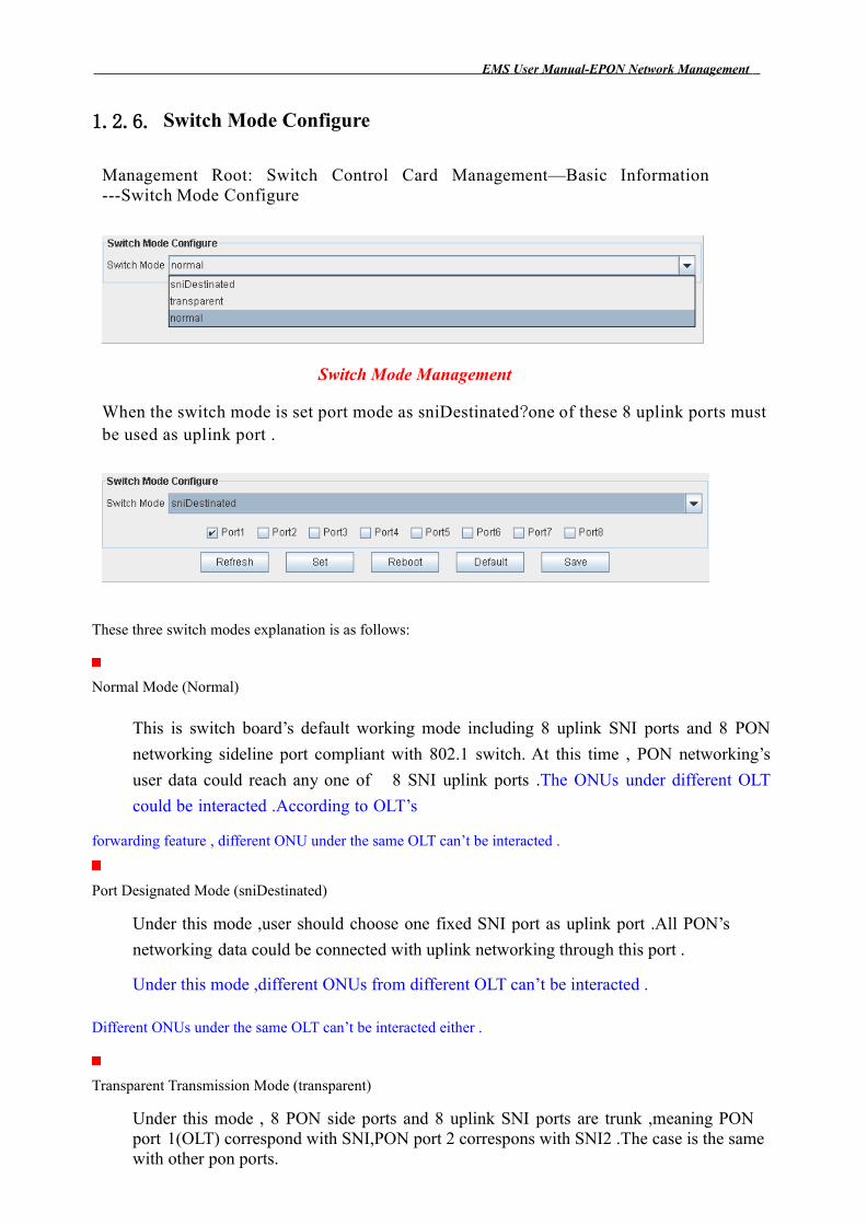
1.2.6. Switch Mode Configure
Management Root: Switch Control Card Management—Basic Information ---Switch Mode Configure
Switch Mode Management
When the switch mode is set port mode as sniDestinated?one of these 8 uplink ports must be used as uplink port .
These three switch modes explanation is as follows:
Normal Mode (Normal)
This is switch board’s default working mode including 8 uplink SNI ports and 8 PON
networking sideline port compliant with 802.1 switch. At this time , PON networking’s
user data could reach any one of 8 SNI uplink ports .The ONUs under different OLT
could be interacted .According to OLT’s
forwarding feature , different ONU under the same OLT can’t be interacted .
Port Designated Mode (sniDestinated)
Under this mode ,user should choose one fixed SNI port as uplink port .All PON’s
networking data could be connected with uplink networking through this port .
Under this mode ,different ONUs from different OLT can’t be interacted .
Different ONUs under the same OLT can’t be interacted either .
Transparent Transmission Mode (transparent)
Under this mode , 8 PON side ports and 8 uplink SNI ports are trunk ,meaning PON port 1(OLT) correspond with SNI,PON port 2 correspons with SNI2 .The case is the same with other pon ports.
EMS Us e r Manual-EPON N e twork Manag e m e nt
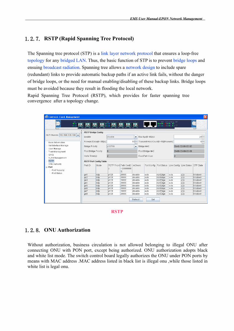
1.2.7. RSTP (Rapid Spanning Tree Protocol)
The Spanning tree protocol (STP) is a link layer network protocol that ensures a loop-free
topology for any bridged LAN. Thus, the basic function of STP is to prevent bridge loops and
ensuing broadcast radiation. Spanning tree allows a network design to include spare
(redundant) links to provide automatic backup paths if an active link fails, without the danger
of bridge loops, or the need for manual enabling/disabling of these backup links. Bridge loops
must be avoided because they result in flooding the local network.
Rapid Spanning Tree Protocol (RSTP), which provides for faster spanning tree convergence after a topology change.
RSTP
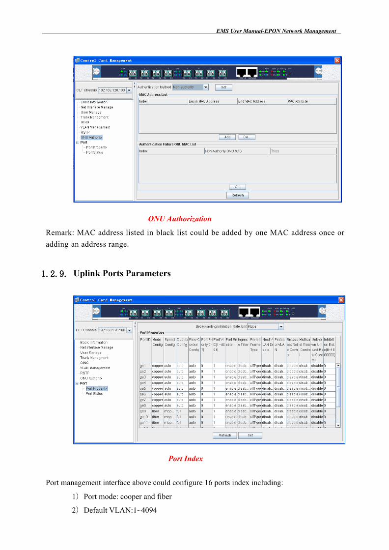
1.2.8. ONU Authorization
Without authorization, business circulation is not allowed belonging to illegal ONU after connecting ONU with PON port, except being authorized. ONU authorization adopts black and white list mode. The switch control board legally authorizes the ONU under PON ports by means with MAC address .MAC address listed in black list is illegal onu ,while those listed in white list is legal onu.
EMS Us e r Manual-EPON N e twork Manag e m e nt
ONU Authorization
Remark: MAC address listed in black list could be added by one MAC address once or
adding an address range.
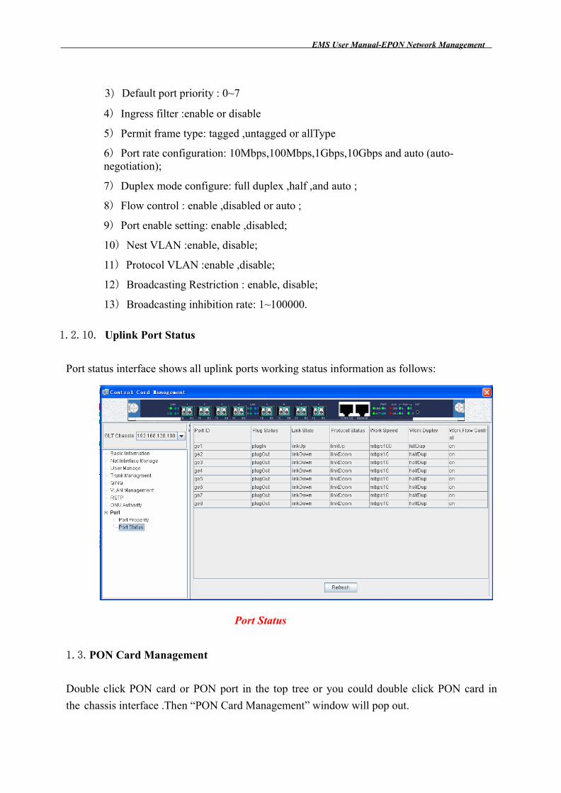
1.2.9. Uplink Ports Parameters
Port Index
Port management interface above could configure 16 ports index including:
1) Port mode: cooper and fiber
2) Default VLAN:1~4094
EMS Us e r Manual-EPON N e twork Manag e m e nt
3) Default port priority : 0~7
4) Ingress filter :enable or disable
5) Permit frame type: tagged ,untagged or allType
6) Port rate configuration: 10Mbps,100Mbps,1Gbps,10Gbps and auto (auto-negotiation);
7) Duplex mode configure: full duplex ,half ,and auto ;
8) Flow control : enable ,disabled or auto ;
9) Port enable setting: enable ,disabled;
10) Nest VLAN :enable, disable;
11) Protocol VLAN :enable ,disable;
12) Broadcasting Restriction : enable, disable;
13) Broadcasting inhibition rate: 1~100000.
1.2.10. Uplink Port Status
Port status interface shows all uplink ports working status information as follows:
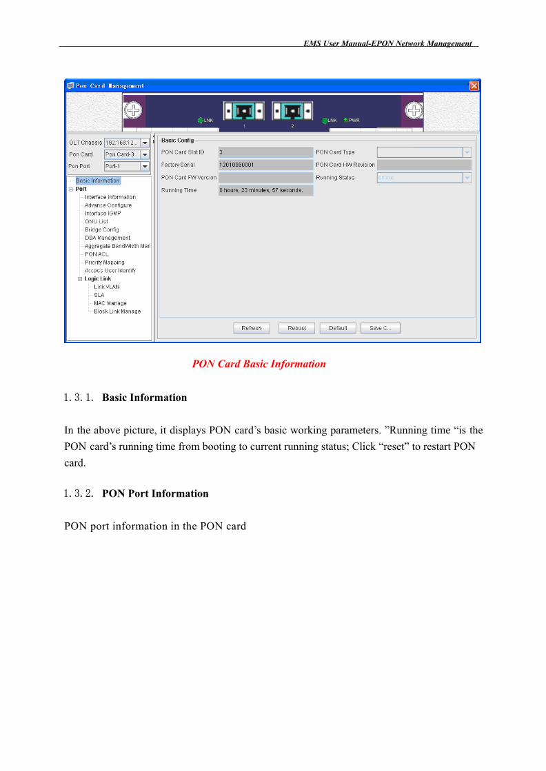
Port Status
1.3.PON Card Management
Double click PON card or PON port in the top tree or you could double click PON card in
the chassis interface .Then “PON Card Management” window will pop out.
EMS Us e r Manual-EPON N e twork Manag e m e nt
PON Card Basic Information
1.3.1. Basic Information
In the above picture, it displays PON card’s basic working parameters. ”Running time “is the
PON card’s running time from booting to current running status; Click “reset” to restart PON
card.
1.3.2. PON Port Information
PON port information in the PON card
EMS Us e r Manual-EPON N e twork Manag e m e nt
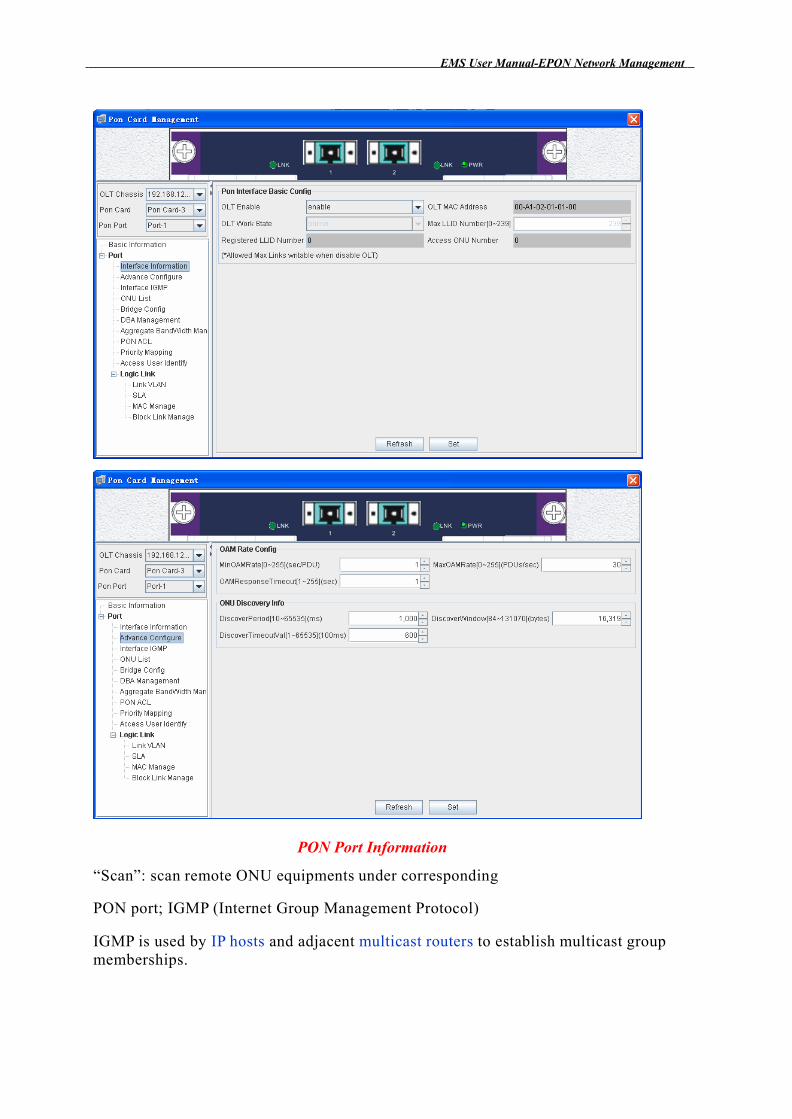
PON Port Information
“Scan”: scan remote ONU equipments under corresponding
PON port; IGMP (Internet Group Management Protocol)
IGMP is used by IP hosts and adjacent multicast routers to establish multicast group memberships.
EMS Us e r Manual-EPON N e twork Manag e m e nt
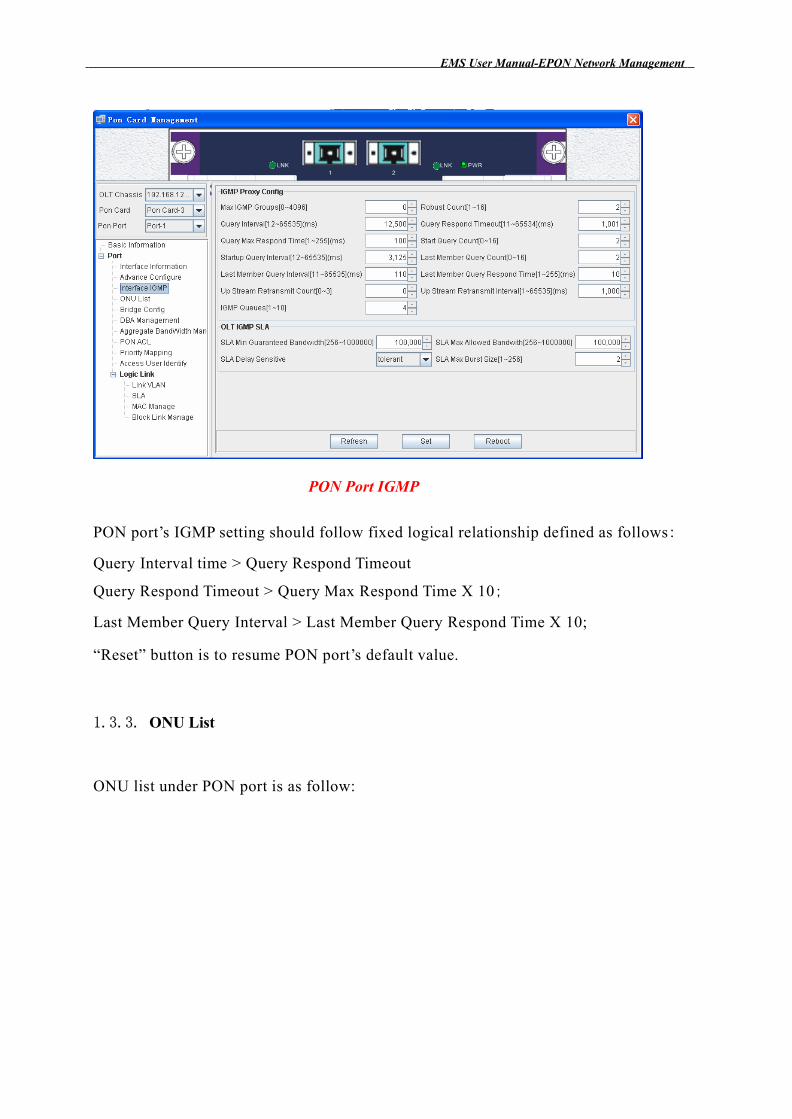
PON Port IGMP
PON port’s IGMP setting should follow fixed logical relationship defined as follows:
Query Interval time > Query Respond Timeout
Query Respond Timeout > Query Max Respond Time X 10;
Last Member Query Interval > Last Member Query Respond Time X 10;
“Reset” button is to resume PON port’s default value.
1.3.3. ONU List
ONU list under PON port is as follow:
EMS Us e r Manual-EPON N e twork Manag e m e nt
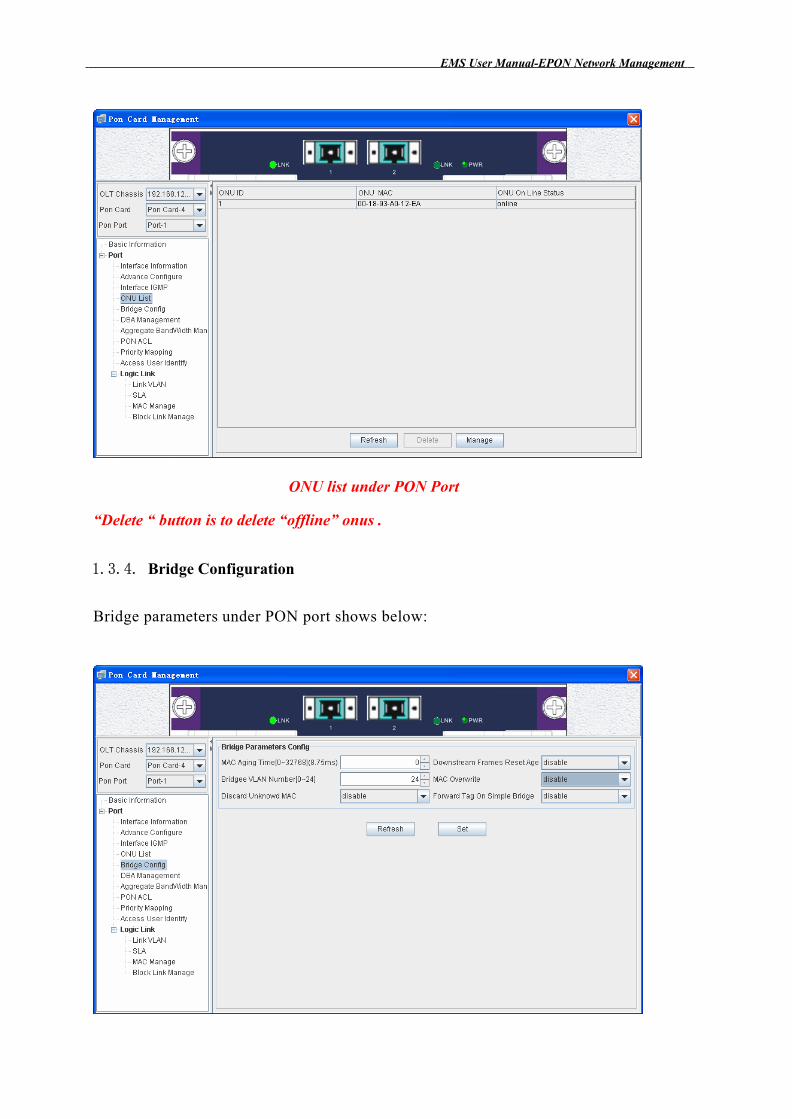
ONU list under PON Port
“Delete “ button is to delete “offline” onus .
1.3.4. Bridge Configuration
Bridge parameters under PON port shows below:
EMS Us e r Manual-EPON N e twork Manag e m e nt
Bridge Parameters Configuration under PON Port
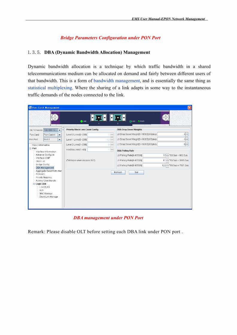
1.3.5. DBA (Dynamic Bandwidth Allocation) Management
Dynamic bandwidth allocation is a technique by which traffic bandwidth in a shared
telecommunications medium can be allocated on demand and fairly between different users of
that bandwidth. This is a form of bandwidth management, and is essentially the same thing as
statistical multiplexing. Where the sharing of a link adapts in some way to the instantaneous
traffic demands of the nodes connected to the link.
DBA management under PON Port
Remark: Please disable OLT before setting each DBA link under PON port .
EMS Us e r Manual-EPON N e twork Manag e m e nt
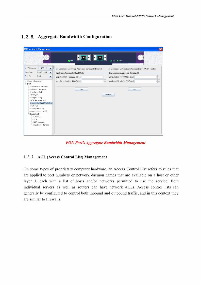
1.3.6. Aggregate Bandwidth Configuration
PON Port’s Aggregate Bandwidth Management
1.3.7. ACL (Access Control List) Management
On some types of proprietary computer hardware, an Access Control List refers to rules that
are applied to port numbers or network daemon names that are available on a host or other
layer 3, each with a list of hosts and/or networks permitted to use the service. Both
individual servers as well as routers can have network ACLs. Access control lists can
generally be configured to control both inbound and outbound traffic, and in this context they
are similar to firewalls.
EMS Us e r Manual-EPON N e twork Manag e m e nt
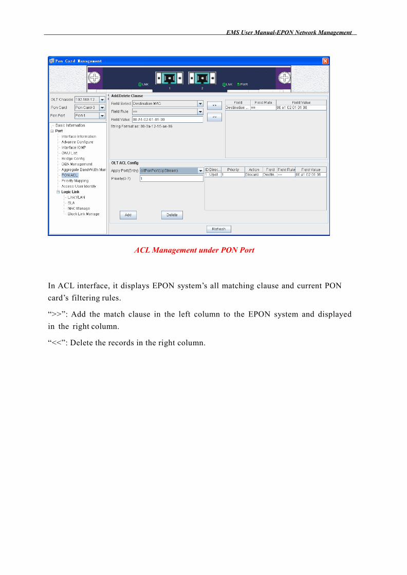
ACL Management under PON Port
In ACL interface, it displays EPON system’s all matching clause and current PON
card’s filtering rules.
“>>”: Add the match clause in the left column to the EPON system and displayed
in the right column.
“<<”: Delete the records in the right column.
EMS Us e r Manual-EPON N e twork Manag e m e nt
1.3.8. Priority Mapping
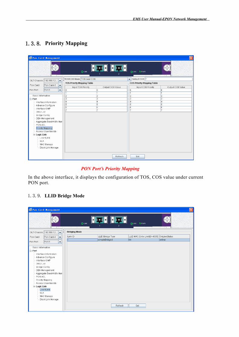
PON Port’s Priority Mapping
In the above interface, it displays the configuration of TOS, COS value under current PON port.
1.3.9. LLID Bridge Mode
EMS Us e r Manual-EPON N e twork Manag e m e nt
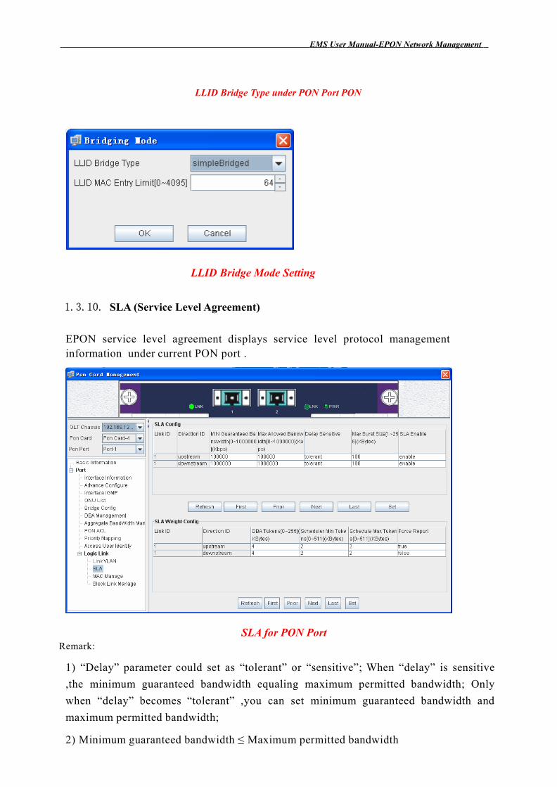
LLID Bridge Type under PON Port PON
LLID Bridge Mode Setting
1.3.10. SLA (Service Level Agreement)
EPON service level agreement displays service level protocol management information under current PON port .
Remark:SLA for PON Port
1) “Delay” parameter could set as “tolerant” or “sensitive”; When “delay” is sensitive
,the minimum guaranteed bandwidth equaling maximum permitted bandwidth; Only
when “delay” becomes “tolerant” ,you can set minimum guaranteed bandwidth and
maximum permitted bandwidth;
2) Minimum guaranteed bandwidth ≤ Maximum permitted bandwidth
1.3.11. MAC Address Management
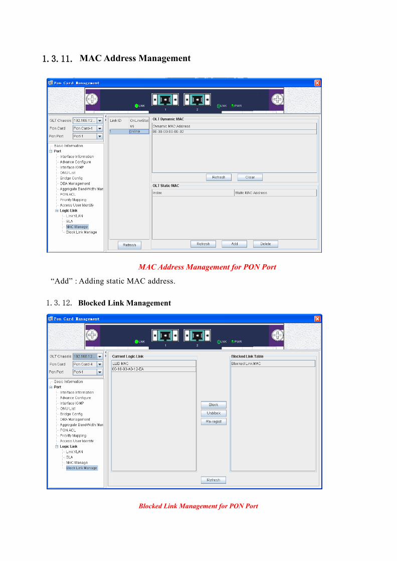
MAC Address Management for PON Port
“Add” : Adding static MAC address.
1.3.12. Blocked Link Management
Blocked Link Management for PON Port
1.4.ONU Management
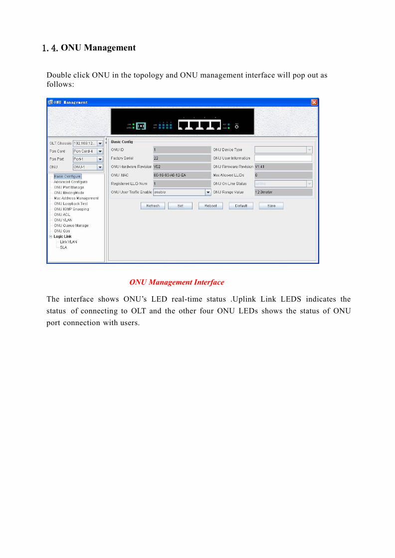
Double click ONU in the topology and ONU management interface will pop out as follows:
ONU Management Interface
The interface shows ONU’s LED real-time status .Uplink Link LEDS indicates the
status of connecting to OLT and the other four ONU LEDs shows the status of ONU
port connection with users.
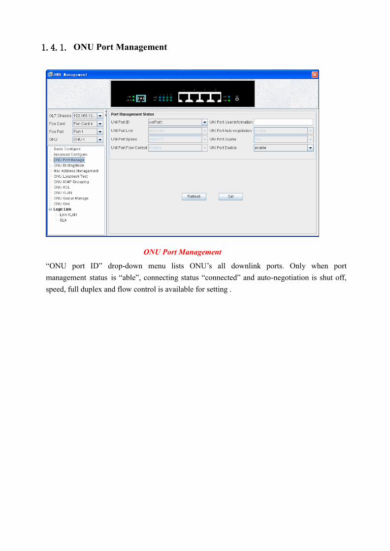
1.4.1. ONU Port Management
ONU Port Management
“ONU port ID” drop-down menu lists ONU’s all downlink ports. Only when port
management status is “able”, connecting status “connected” and auto-negotiation is shut off,
speed, full duplex and flow control is available for setting .
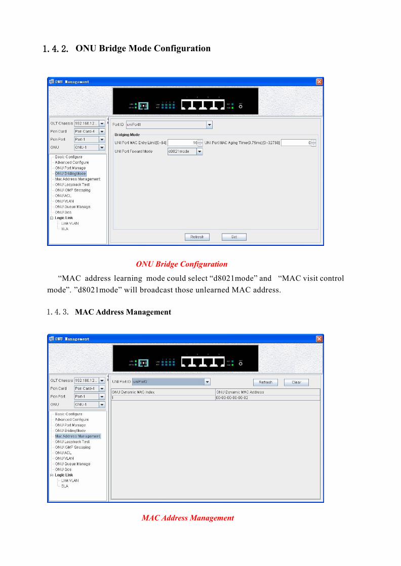
1.4.2. ONU Bridge Mode Configuration
ONU Bridge Configuration
“MAC address learning mode could select “d8021mode” and “MAC visit control
mode”. ”d8021mode” will broadcast those unlearned MAC address.
1.4.3. MAC Address Management
MAC Address Management
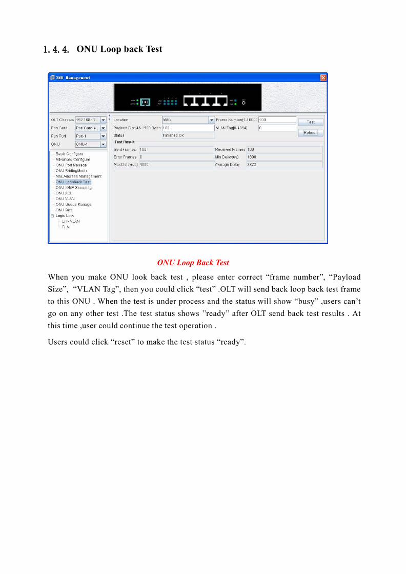
1.4.4. ONU Loop back Test
ONU Loop Back Test
When you make ONU look back test , please enter correct “frame number”, “Payload
Size”, “VLAN Tag”, then you could click “test” .OLT will send back loop back test frame
to this ONU . When the test is under process and the status will show “busy” ,users can’t
go on any other test .The test status shows ”ready” after OLT send back test results . At
this time ,user could continue the test operation .
Users could click “reset” to make the test status “ready”.
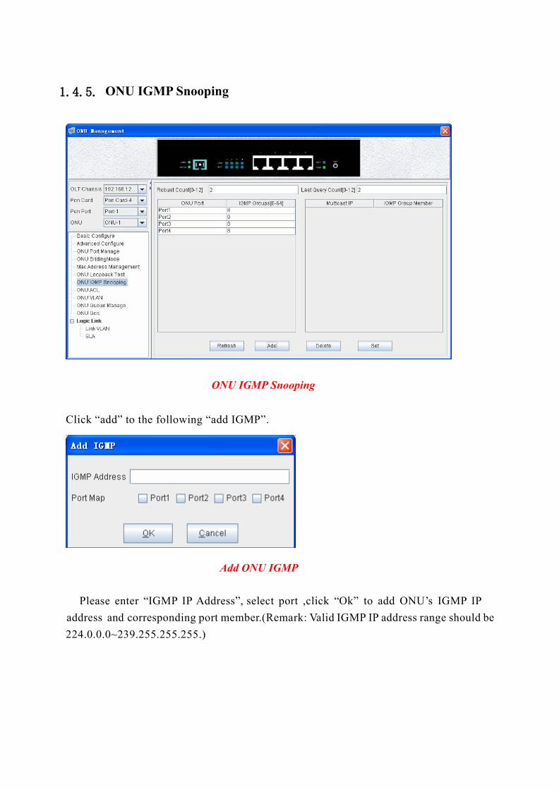
1.4.5. ONU IGMP Snooping
ONU IGMP Snooping
Click “add” to the following “add IGMP”.
Add ONU IGMP
Please enter “IGMP IP Address”, select port ,click “Ok” to add ONU’s IGMP IP
address and corresponding port member.(Remark: Valid IGMP IP address range should be
224.0.0.0~239.255.255.255.)
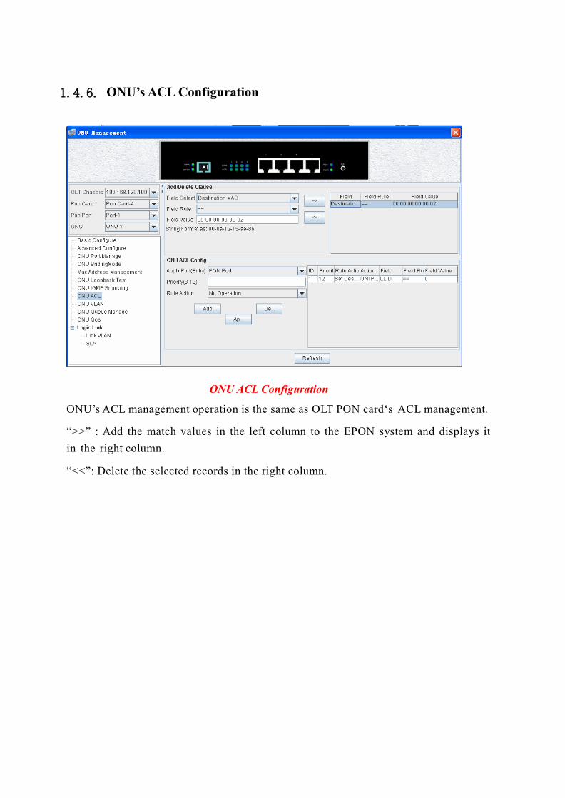
1.4.6. ONU’s ACL Configuration
ONU ACL Configuration
ONU’s ACL management operation is the same as OLT PON card‘s ACL management.
“>>” : Add the match values in the left column to the EPON system and displays it
in the right column.
“<<”: Delete the selected records in the right column.
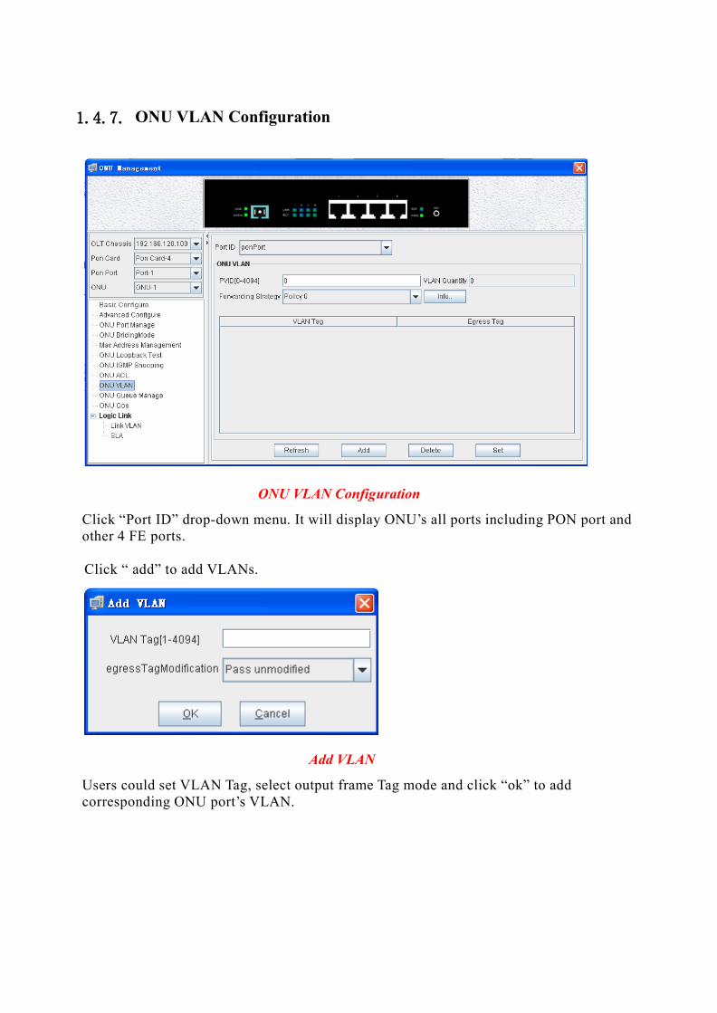
1.4.7. ONU VLAN Configuration
ONU VLAN Configuration
Click “Port ID” drop-down menu. It will display ONU’s all ports including PON port and other 4 FE ports.
Click “ add” to add VLANs.
Add VLAN
Users could set VLAN Tag, select output frame Tag mode and click “ok” to add corresponding ONU port’s VLAN.
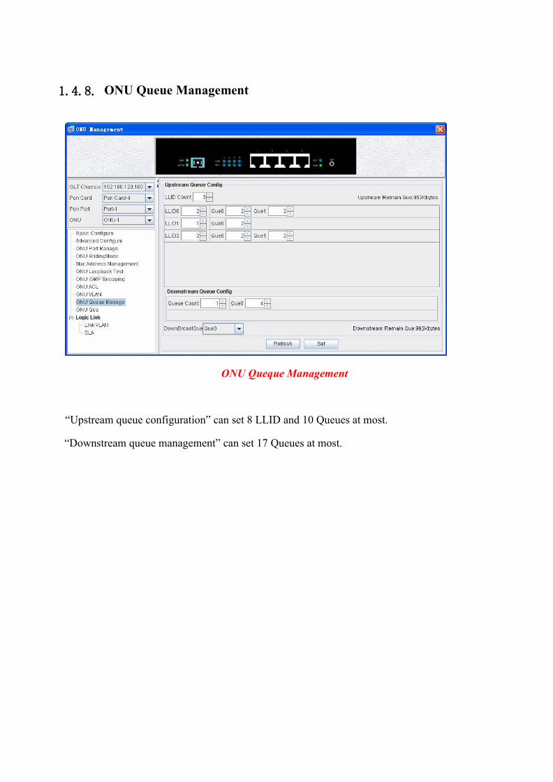
1.4.8. ONU Queue Management
ONU Queque Management
“Upstream queue configuration” can set 8 LLID and 10 Queues at most.
“Downstream queue management” can set 17 Queues at most.
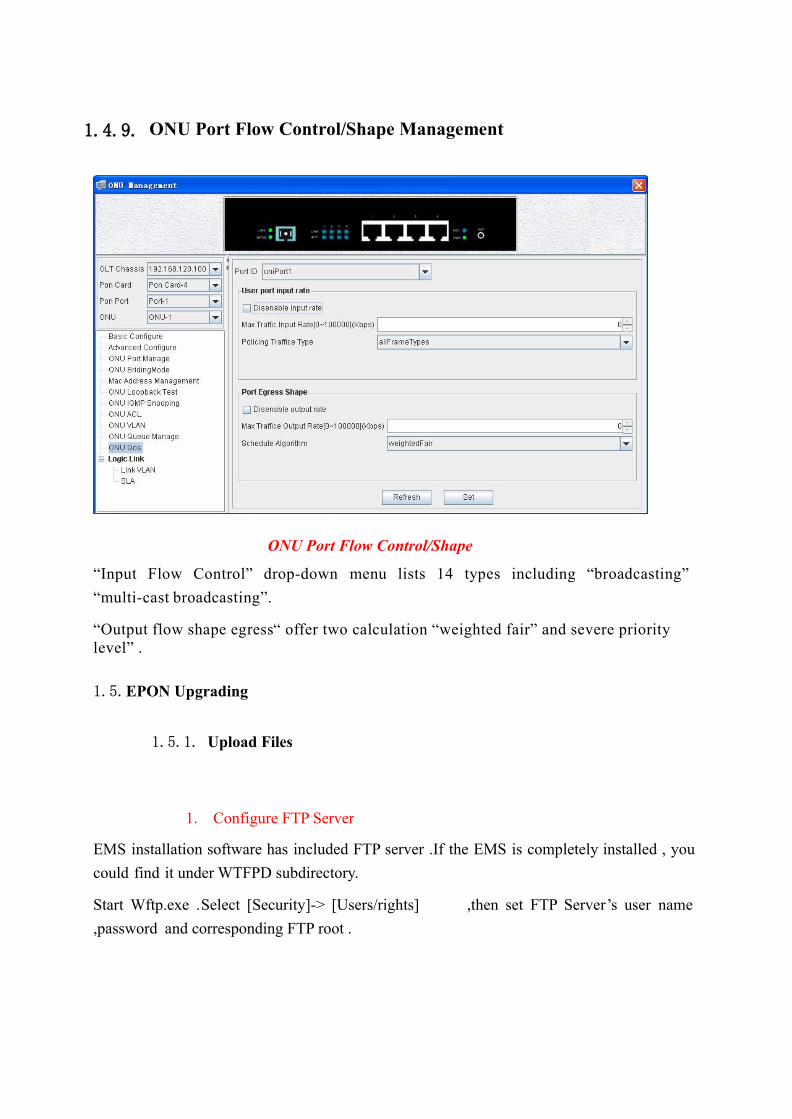
1.4.9. ONU Port Flow Control/Shape Management
ONU Port Flow Control/Shape
“Input Flow Control” drop-down menu lists 14 types including “broadcasting”
“multi-cast broadcasting”.
“Output flow shape egress“ offer two calculation “weighted fair” and severe priority level” .
1.5.EPON Upgrading
1.5.1. Upload Files
1. Configure FTP Server
EMS installation software has included FTP server .If the EMS is completely installed , you
could find it under WTFPD subdirectory.
Start Wftp.exe .Select [Security]-> [Users/rights] ,then set FTP Server’s user name
,password and corresponding FTP root .
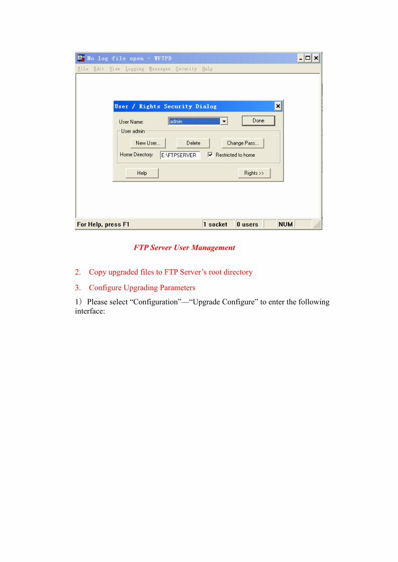
FTP Server User Management
2. Copy upgraded files to FTP Server’s root directory
3. Configure Upgrading Parameters
1) Please select “Configuration”—“Upgrade Configure” to enter the following interface:
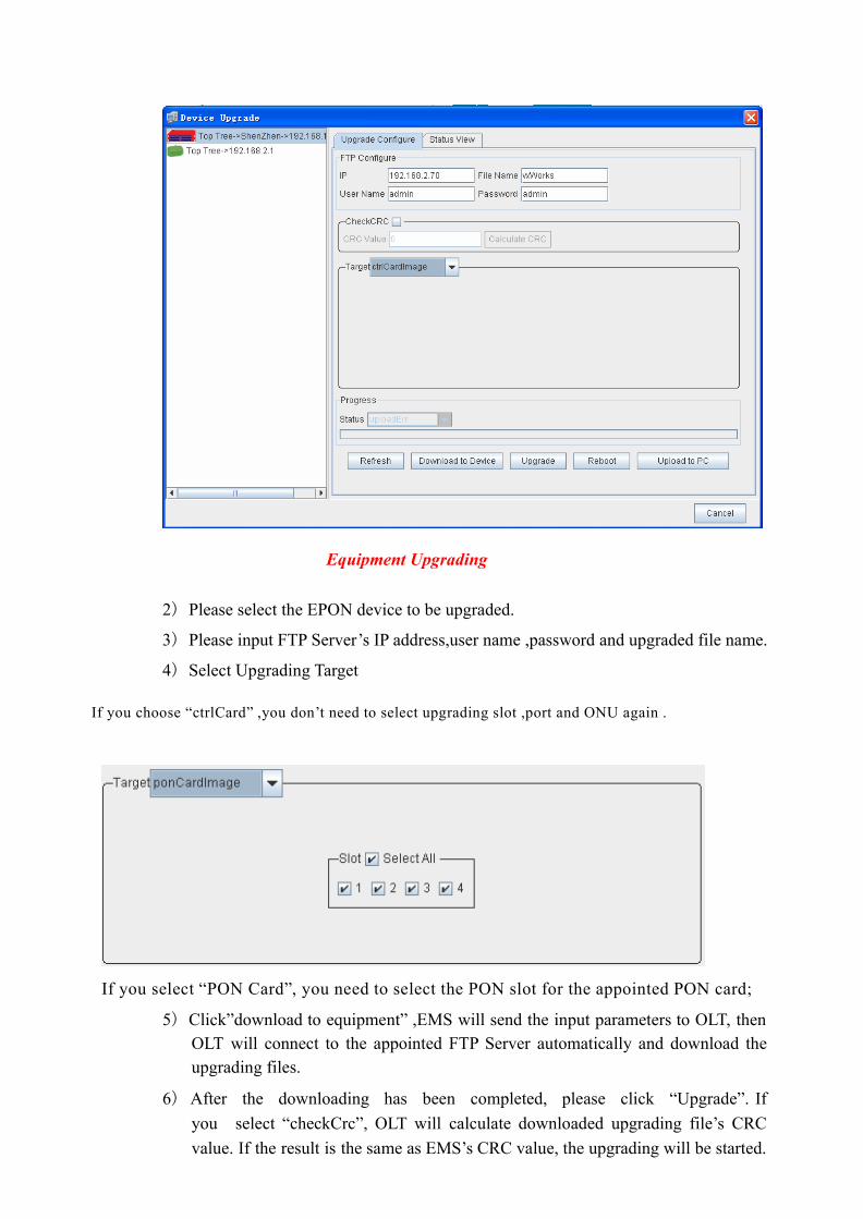
Equipment Upgrading
2) Please select the EPON device to be upgraded.
3) Please input FTP Server’s IP address,user name ,password and upgraded file name.
4) Select Upgrading Target
If you choose “ctrlCard” ,you don’t need to select upgrading slot ,port and ONU again .
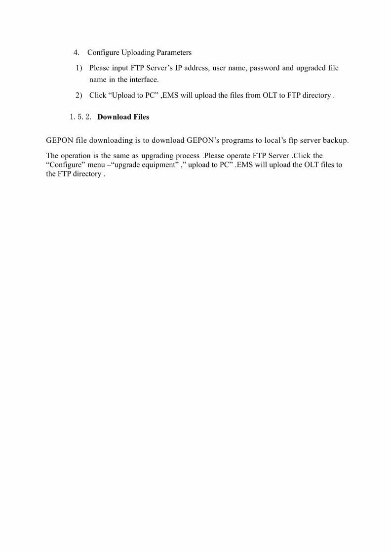
If you select “PON Card”, you need to select the PON slot for the appointed PON card;
5) Click”download to equipment” ,EMS will send the input parameters to OLT, then OLT will connect to the appointed FTP Server automatically and download the upgrading files.
6) After the downloading has been completed, please click “Upgrade”. If
you select “checkCrc”, OLT will calculate downloaded upgrading file’s CRC
value. If the result is the same as EMS’s CRC value, the upgrading will be started.
4. Configure Uploading Parameters
1) Please input FTP Server’s IP address, user name, password and upgraded file
name in the interface.
2) Click “Upload to PC” ,EMS will upload the files from OLT to FTP directory .
1.5.2. Download Files
GEPON file downloading is to download GEPON’s programs to local’s ftp server backup.
The operation is the same as upgrading process .Please operate FTP Server .Click the “Configure” menu –“upgrade equipment” ,” upload to PC” .EMS will upload the OLT files to the FTP directory .