Embed Size (px)
Citation preview

EnergyPlus Documentation
Application Guide for EMSEnergy Management System User Guide(a.k.a. The Book of Erl)
COPYRIGHT (c) 1996-2015 THE BOARD OF TRUSTEES OF THE UNIVERSITY OF ILLINOIS AND THE REGENTS OF THEUNIVERSITY OF CALIFORNIA THROUGH THE ERNEST ORLANDO LAWRENCE BERKELEY NATIONAL LABORATORY.ALL RIGHTS RESERVED. NO PART OF THIS MATERIAL MAY BE REPRODUCED OR TRANSMITTED IN ANY FORM ORBY ANY MEANS WITHOUT THE PRIOR WRITTEN PERMISSION OF THE UNIVERSITY OF ILLINOIS OR THE ERNESTORLANDO LAWRENCE BERKELEY NATIONAL LABORATORY. ENERGYPLUS IS A TRADEMARK OF THE USDEPARTMENT OF ENERGY.
TM
EnergyPlus Documentation Page 1 of 114

Table of contents
EnergyPlusTM DocumentationApplication Guide for EMS
Energy Management System User GuideIntroduction
BackgroundOrganization
EnergyPlus Runtime LanguageStatement Keywords
Rules for IF blocks:Rules for WHILE blocks:
VariablesBuilt-In VariablesTrend Variables
ExpressionsBuilt-In Functions
Built-in Math FunctionsBuilt-In Simulation Management FunctionsBuilt-in Trend Variable FunctionsBuilt-in Psychrometric FunctionsBuilt-in Curve and Table Functions
Internal VariablesZone GeometryInternal Gains
People Count Design LevelLighting Power Design LevelPlug and Process Power Design LevelGas Process Power Design LevelProcess District Heat Design LevelProcess Steam District Heat Design LevelOther Equipment Design LevelSimple Zone Baseboard Capacity
HVAC SystemsAirTerminal:SingleDuct:UncontrolledFan Nominal RatingsUnitary HVAC Nominal RatingsOutdoor Air Mixer Nominal RatingsPump Nominal RatingsLow Temperature Radiant Hydronic
On-Site Electricity ProductionGenerator Nominal RatingsElectrical Storage
SizingSizing:ZoneSizing:SystemSizing:Plant
EMS SensorsVariable Types
EnergyPlus Documentation Page 2 of 114

SchedulesEMS Actuators
HVAC SystemsSystem Node SetpointsZone HVAC ControlPlant Supervisory ControlOutdoor Air System Node ConditionsAirLoopHVAC Availability StatusIdeal Loads Air SystemFanDX Cooling CoilsUnitary EquipmentAirTerminal:SingleDuct:UncontrolledOutdoor Air ControllerPlant Load ProfilePumpWindow Air ConditionerLow Temperature Radiant HydronicVariable Refrigerant Flow Heat Pump Air ConditionerVariable Refrigerant Flow Terminal Unit
Thermal EnvelopeWindow Shading ControlSlat AngleSurface Convection Heat Transfer CoefficientMaterial Surface PropertiesSurface Construction StateSurface Boundary Conditions
Air MovementZone InfiltrationZone VentilationZone MixingZone Cross MixingAirflow Network Openings
Internal Gains and Exterior LightsPeopleLightsElectric EquipmentGas EquipmentHot Water EquipmentSteam EquipmentOther EquipmentBaseboardExterior Lights
On-Site Electricity ProductionGenerator DispatchElectrical Storage
RefrigerationCondenser Operation
EnergyPlus Documentation Page 3 of 114

GeneralSchedulesCurvesWeather Data
SizingSizing:ZoneSystem Sizing
EMS Calling PointsBegin New EnvironmentAfter New Environment Warmup Is CompleteBegin Timestep Before PredictorAfter Predictor Before HVAC ManagersAfter Predictor After HVAC ManagersInside HVAC System Iteration LoopEnd of Zone Timestep Before ReportingEnd of Zone Timestep After ReportingEnd of System Timestep Before HVAC ReportingEnd of System Timestep After HVAC ReportingEnd of Zone SizingEnd of System SizingAfter Component Model Input has Been Read InUser Defined Component Model
User-Defined Component ModelsCommon CharacteristicsZone Forced Air Unit
Primary Air ConnectionSecondary Air ConnectionPlant ConnectionsWater UseAmbient Zone
Air Terminal UnitPrimary Air ConnectionSecondary Air ConnectionPlant ConnectionsWater UseAmbient Zone
Air CoilAir ConnectionsPlant ConnectionsWater UseAmbient Zone
Plant ComponentPlant ConnectionsAir ConnectionWater UseAmbient Zone
EMS ExamplesExample 1. Whole-Building Average Zone Air Temperature
EnergyPlus Documentation Page 4 of 114

Problem StatementEMS Design DiscussionEMS Input Objects
Example 2. Traditional Setpoint and Availability ManagersProblem StatementEMS Design DiscussionEMS Input Objects
Example 3. Hygro-thermal Window Opening Control for Airflow NetworkProblem StatementEMS Design DiscussionEMS Input Objects
Example 4. Halt Program Based on ConstraintProblem StatementEMS Design DiscussionEMS Input Objects
Example 5. Computed ScheduleProblem StatementEMS Design DiscussionEMS Input Objects
Example 6. Window Shade ControlProblem StatementEMS Design DiscussionEMS Input Objects
Example 7. Constant Volume Purchased Air SystemProblem StatementEMS Design DiscussionEMS Input Objects
Example 8. System Sizing with Discrete Package SizesProblem StatementEMS Design DiscussionEMS Input Objects
Example 9. Demand ManagementProblem StatementEMS Design DiscussionEMS Input Objects
Example 10. Plant Loop Override ControlProblem StatementEMS Design DiscussionEMS Input Objects
Example 11. Performance Curve Result OverrideProblem StatementEMS Design DiscussionEMS Input Objects
Example 12. Variable Refrigerant Flow System OverrideProblem StatementEMS Design DiscussionEMS Input Objects
Example 13. Surface Construction Actuator for Thermochromic Window
EnergyPlus Documentation Page 5 of 114

Problem StatementEMS Design DiscussionEMS Input Objects
Debugging EMS ProgramsERR FileEDD FileLine TraceDebugging Strategies
EnergyPlus Documentation Page 6 of 114

IntroductionThis document provides an in-depth look at the Energy Management System (EMS) feature in EnergyPlusand provides a way to develop custom control and modeling routines for EnergyPlus models. EMS is anadvanced feature of EnergyPlus and is not for beginners. You will need to write your own custom computerprograms and have a thorough understanding of how you want your models to behave. If you areintimidated by the idea of writing computer programs to adjust the fine details of how an EnergyPlus modelruns, be aware that EMS is not for all (or even most) users. However, if you relish the idea of being able towrite small computer programs that override some annoying behavior, you may find that writing Erlprograms can solve many problems faced by energy modelers. EMS is a complicated feature and thisapplication guide augments the Input/Output Reference by providing an overall discussion of how to useEMS.
EMS provides high-level, supervisory control to override selected aspects of EnergyPlus modeling. A smallprogramming language called EnergyPlus Runtime Language (Erl) is used to describe the controlalgorithms. EnergyPlus interprets and executes your Erl program as the model is being run. This guideserves as a programming manual for Erl and attempts to show you how to customize your EnergyPlussimulations.
BackgroundWe used the operations manual for a common commercial brand of EMS to guide the initial formulation ofErl. The circa 2000 EMS language from a major manufacturer is a good example because it uses a full-featured EMS language and does not rely on a graphical user interface.
OrganizationWe first describe Erl, then discuss its rules and features, including syntax for writing statements, variables,expressions, and built-in functions. We then discuss sensors, actuators, and calling points for the EMS.Then we describe a set of examples applications for EMS. The last section provides information aboutdebugging Erl programs.
EnergyPlus Runtime LanguageErl is the simplified programming language used to define the EMS control and modeling programs. Thissection describes the rules and syntax for using Erl to write programs.
Statement KeywordsEvery programming language has instructions or commands that tell the processor what to do. Erl supportsa few types of program statements. Each line of an Erl program begins with a statement keyword. Thesyntax for each line depends on the keyword that starts that line. Only those listed in Table 1 are allowed.
Keyword Syntax Statement Description
EnergyPlus Documentation Page 7 of 114
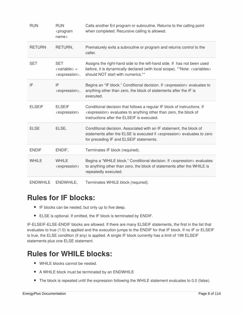
RUN RUN<programname>
Calls another Erl program or subroutine. Returns to the calling pointwhen completed. Recursive calling is allowed.
RETURN RETURN, Prematurely exits a subroutine or program and returns control to thecaller.
SET SET<variable> =<expression>,
Assigns the right-hand side to the left-hand side. If has not been usedbefore, it is dynamically declared (with local scope). **Note: <variables>should NOT start with numerics.**
IF IF<expression>,
Begins an “IF block.” Conditional decision. If <expression> evaluates toanything other than zero, the block of statements after the IF isexecuted.
ELSEIF ELSEIF<expression>
Conditional decision that follows a regular IF block of instructions. If<expression> evaluates to anything other than zero, the block ofinstructions after the ELSEIF is executed.
ELSE ELSE, Conditional decision. Associated with an IF statement, the block ofstatements after the ELSE is executed if <expression> evaluates to zerofor preceding IF and ELSEIF statements.
ENDIF ENDIF, Terminates IF block (required).
WHILE WHILE<expression>
Begins a “WHILE block.” Conditional decision. If <expression> evaluatesto anything other than zero, the block of statements after the WHILE isrepeatedly executed.
ENDWHILE ENDWHILE, Terminates WHILE block (required).
Rules for IF blocks:IF blocks can be nested, but only up to five deep.
ELSE is optional. If omitted, the IF block is terminated by ENDIF.
IF-ELSEIF-ELSE-ENDIF blocks are allowed. If there are many ELSEIF statements, the first in the list thatevaluates to true (1.0) is applied and the execution jumps to the ENDIF for that IF block. If no IF or ELSEIFis true, the ELSE condition (if any) is applied. A single IF block currently has a limit of 199 ELSEIFstatements plus one ELSE statement.
Rules for WHILE blocks:WHILE blocks cannot be nested.
A WHILE block must be terminated by an ENDWHILE
The block is repeated until the expression following the WHILE statement evaluates to 0.0 (false).
EnergyPlus Documentation Page 8 of 114

Once the WHILE loop is entered, there is a maximum limit on the number of times the loop can berepeated. The limit is set at one million repetitions to protect against the possibility of an Erl programentering an infinite loop if the WHILE loop’s expression is malformed so as to never evaluate to 0.0(false).
Erl programs are entered into the input data file (IDF) using the input objects calledEnergyManagementSystem:Program and EnergyManagementSystem:Subroutine. These objects useindividual fields to store the statements for an Erl program. As with most EnergyPlus objects, each field isseparated by a comma and typically given a separate line of text for readability. In this case, each field canbe considered a separate line of Erl program code. Every input field (line of code) must conform to thefollowing rules:
Every input field contains only one statement.
Every field begins with a statement keyword that identifies what that particular line of code is doing.
The syntax for each statement depends on the keyword.
All field content (keywords, variable names, etc.) is case insensitive.
A comma (or semicolon if it is the last field) marks the end of every statement.
The maximum length for a field is 100 characters. If you enter a longer field, it will be truncated tothe first 100 characters. This can have subtle effects if the remaining portion forms a viableexpression.
The “!” character is for comments.
REMEMBER, every line needs to end in a comma or, if it is the last in the program, a semicolon.
VariablesVariables are important to any programming language. All Erl variables, except trend variables, are treatedthe same way in Erl and can be used interchangeably with any instruction.
The rules for selecting names of EMS variables are:
No spaces are allowed in user-defined variable names.
Underscore (“_”) is the only special character allowed in variable names.
Variable names are not case sensitive.
Names of variables with global scope must be unique.
Variables cannot be declared with the same name as a built-in variable.
Variables can be alpha numeric strings but should NOT start with a numeric.
The rules for using EMS variables are:
All numeric variables are treated as floating point numbers. You use the underlying Fortran languagefeatures to handle these as double precision real numbers.
You can use the SET statement to reassign sensor variables and built-in variables.
Actuator variables use SET to perform control actions.EnergyPlus Documentation Page 9 of 114

EMS variables can have either local or global scope. Global scope means that the variables can be usedacross Erl programs and always refer to the same instance of a particular variable. Global variables musthave unique names. Local scope means that variables can be used only within a given Erl program.
Erl programs have eight types of variables:
Sensor. Each EnergyManagementSystem:Sensor input object declares a user-defined variable andmaps it to a variable elsewhere in EnergyPlus (via output variables). Variables so declared haveglobal scope and are used to get time-varying input data from elsewhere in the EnergyPlus model.
Actuator. Each EnergyManagementSystem:Actuator input object declares a user-defined Erlvariable and maps it to a variable elsewhere in EnergyPlus. Variables so declared have global scopeand are used to set control results elsewhere in the EnergyPlus model.
Local. Local variables do not need to be explicitly declared. These undeclared variables will beautomatically registered as EMS variables with local scope. This allows you to create new variables“on the fly.” Local variables can be used for temporary storage of intermediate results.
Global. EnergyManagementSystem:GlobalVariable input objects are used to declare variables witha user-defined name and global scope. Global variables can be used to store intermediate resultsthat span across Erl programs. Because the Erl compiler does not support functions or argumentpassing, global variables have an important role in using subroutines. These variables are globalonly within Erl and not with respect to code elsewhere in EnergyPlus.
Built-in. The EMS system automatically declares a set of built-in variables with predefined names.These variables have global scope. The built-in variables are always created and cannot beeliminated.
Internal. Each EnergyManagementSystem:InternalVariable input object declares a user-defined Erlvariable and maps it to a variable elsewhere in EnergyPlus. Variables so declared have global scopeand are used to get static input data from elsewhere in EnergyPlus.
Trend. Each EnergyManagementSystem:TrendVariable input object declares a user-defined Erltrend variable and maps it to a global Erl variable for logging. Trend variables are used to store thehistory of Erl variables. Trend variables differ from other Erl variables in that they can be put to useonly through the built-in trend functions (see Table 6).
Index. Each EnergyManagementSystem:CurveOrTableIndexVariable and/orEnergyManagementSystem:ConstructionIndexVariable declares a user defined Erl variable andmaps it to a specific item in the IDF of indicated type.
Built-in variables, internal variables, and sensor variables are primarily used to get information about thestate of the simulation. However, because all variables are treated alike, built-in variables and sensorvariables can also be overwritten by the SET instruction. (This applies within the EMS only; the variables inthe rest of EnergyPlus program will not be overwritten.) This allows you to reassign constants such as “on”and “off” as well as the values of the other built-in variables and sensor variables. There is really noproblem with this, as long as you know what you are doing. One possible application is to reset a sensorvariable that references the outdoor drybulb temperature so it contains the temperature in degreesFahrenheit instead of Celsius. Regardless of reassignment, sensor variables and the dynamic built-invariables (e.g., date and time) will be cleared and updated with the latest values from EnergyPlus at thenext timestep. Resetting a sensor variable does not have a retroactive effect on the report variable to whichit is mapped.
EnergyPlus Documentation Page 10 of 114

The actuator variable is the counterpart of the sensor variable. Sensor variables are used to get the state ofbuilding systems; actuator variables are used to set the state of building systems. When used with actuatorvariables, the SET instruction performs control actions on the object to which it maps.
Built-In VariablesA set of built-in variables provides date, time, and weather information that is not available via standardreport variables, as well as several handy constant variables such as “true,” “false,” “on,” and “off.” Severalvariables provide access to the time and date information during the course of a simulation. TheCurrentTime, Hour and Minute variables represent the point in time at end of the timestep currently beingsimulated. EnergyPlus primarily operates in standard time and these clock values are not adjusted fordaylight savings time. The built-in variable DaylightSavings time is available for use with the daylightsavings time adjustment feature (see RunPeriodControl:DaylightSavingTime). The duration of simulationtimesteps are available in the variables ZoneTimeStep and SystemTimeStep. The status of whether or notthe simulation is currently during the initial warmup days is available in the variable WarmupFlag.
Table 2 lists the built-in variables that are always available for use in Erl programs.
Table 2. Built-In Unique Variables for Erl
Variable Name Value
Year 1900–2100
Month 1–12
DayOfMonth 1–31
DayOfWeek 1–7 (1 = Sun, 2 = Mon, …)
DayOfYear 1–365
Holiday 0 if not. 1.0, 2.0, etc., for each type of holiday in model
DaylightSavings 0 or 1, 0 if not daylight savings time, 1 if daylight savings time
CurrentTime 0.0-24.0, (fractional hours)
Hour 0–23 (whole hours only)
Minute 1.0–60.0 (fractional minutes)
True 1.0
False 0.0
On 1.0
Off 0.0
EnergyPlus Documentation Page 11 of 114
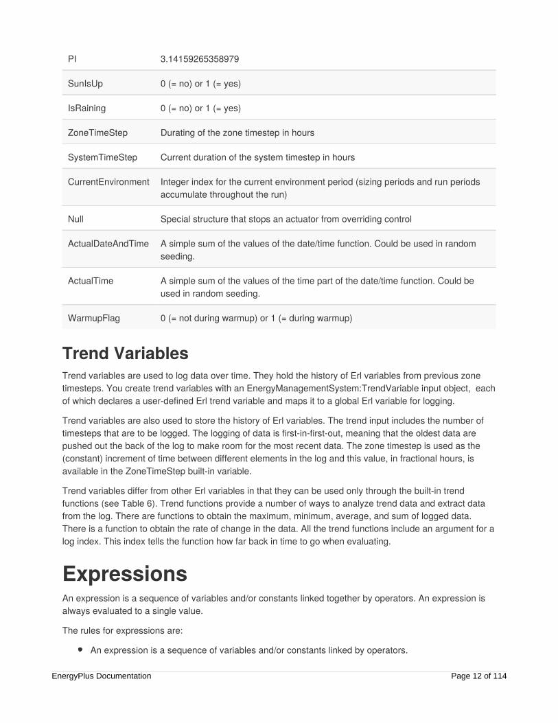
PI 3.14159265358979
SunIsUp 0 (= no) or 1 (= yes)
IsRaining 0 (= no) or 1 (= yes)
ZoneTimeStep Durating of the zone timestep in hours
SystemTimeStep Current duration of the system timestep in hours
CurrentEnvironment Integer index for the current environment period (sizing periods and run periodsaccumulate throughout the run)
Null Special structure that stops an actuator from overriding control
ActualDateAndTime A simple sum of the values of the date/time function. Could be used in randomseeding.
ActualTime A simple sum of the values of the time part of the date/time function. Could beused in random seeding.
WarmupFlag 0 (= not during warmup) or 1 (= during warmup)
Trend VariablesTrend variables are used to log data over time. They hold the history of Erl variables from previous zonetimesteps. You create trend variables with an EnergyManagementSystem:TrendVariable input object, eachof which declares a user-defined Erl trend variable and maps it to a global Erl variable for logging.
Trend variables are also used to store the history of Erl variables. The trend input includes the number oftimesteps that are to be logged. The logging of data is first-in-first-out, meaning that the oldest data arepushed out the back of the log to make room for the most recent data. The zone timestep is used as the(constant) increment of time between different elements in the log and this value, in fractional hours, isavailable in the ZoneTimeStep built-in variable.
Trend variables differ from other Erl variables in that they can be used only through the built-in trendfunctions (see Table 6). Trend functions provide a number of ways to analyze trend data and extract datafrom the log. There are functions to obtain the maximum, minimum, average, and sum of logged data.There is a function to obtain the rate of change in the data. All the trend functions include an argument for alog index. This index tells the function how far back in time to go when evaluating.
ExpressionsAn expression is a sequence of variables and/or constants linked together by operators. An expression isalways evaluated to a single value.
The rules for expressions are:
An expression is a sequence of variables and/or constants linked by operators.
EnergyPlus Documentation Page 12 of 114

Expressions always evaluate to a single value.
Comparison operators evaluate to 1.0 for “true” or 0.0 for “false.”
Compound expressions are allowed and can be organized with parentheses.
The operators shown in Table 3 are available for use in Erl programs.
Table 3. Operators for Erl
Operator Symbol Description Evaluation Order Example
( ) Parentheses left-to-right SET z = 23/(3 + 2)
+ Addition right-to-left SET a = 4 + 5
- Subtraction right-to-left SET b = a - 3
* Multiplication right-to-left SET c = a * b
/ Division left-to-right SET d = b/a
^ Raise to a power left-to-right SET e = c ^ 0.5
== Equality comparison left-to-right IF a == b
<> Inequality comparison left-to-right IF c <> d
> Greater than comparison left-to-right IF a > e
>= Greater than or equal to comparison left-to-right IF a >= 6
< Less than comparison left-to-right IF b < 2
<= Less than or equal to comparison left-to-right IF b <= f
&& Logical AND right-to-left IF c && d
|| Logical OR right-to-left IF c || d
Because expressions can be evaluated to a single value, they can be used in SET and IF statements. Thatmeans both of the following instructions are allowed:
SET a = c < dIF a - 1
In the case of the SET example, the value of “a” is set to 1 if “c” is less than “d”; otherwise, it is set to 0. Forthe IF example, the IF block of instructions are executed if a – 1 is greater than zero.
Compound expressions allow multiple operators to be sequenced or nested. For example:
EnergyPlus Documentation Page 13 of 114

a + b \* 7 / 4.5(a \* 3 + 4) ^ 2(a > b) && (c < d)
For complicated expressions, it helps to make heavy use of parentheses in your equations. By usingparentheses with proper algebraic evaluation in mind to group terms, you can help the Erl parser. Thelanguage processor is simplistic compared to a full-blown programming language and sometimes hasproblems applying the rules of algebra. It is safer to err on the side of extra parentheses and to inspect theresults of complex expressions in the EDD output.
Built-In FunctionsSeveral useful, built-in functions are available for use in Erl programs. You cannot configure these; they areinternal to the language processor inside EnergyPlus. They provide access to a subset of general serviceroutines that are useful inside the main EnergyPlus program or are intrinsic functions available in theunderlying Fortran language. The “@” character is used to signal to the language processor that thefollowing character string defines a built-in function that is used to assign a result to an Erl variable. Thecharacters appended to the “@” operator must be one of the predefined names listed in Table 4, Table 5,Table 6, or Table 7. The syntax of the function call will vary depending on the arguments required by thefunction, but the general structure is:
SET <variable> = @<function name> <argument1> <argument2> … <argumentN>
Where “argument” can be either an Erl variable or a numeric constant.
For example, the following two statements can be used to set the value of an Erl variable calledmySupplyRH to have percent relative humidity.
SET mySupplyRH = @RhFnTdbWPb mySupplyDryblub mySupplyHumRat mySupplyPress
SET mySupplyRH = mySupplyRH * 100
Built-in Math FunctionsTable 4 lists the built-in functions for common mathematical functions. The numerical model for thesefunctions is provided by the underlying Fortran language and the compiler.
Table 4. Built-in Math Functions for Erl
Function Name Description Number ofArguments
@Round Decreases precision of real number argument to nearest wholenumber, remains a real number.
1
@Mod Returns remainder after dividing the first argument by the second. 2
@Sin Sine, returns sine of angle given in radians. 1
@Cos Cosine, returns cosine of angle given in radians. 1
EnergyPlus Documentation Page 14 of 114
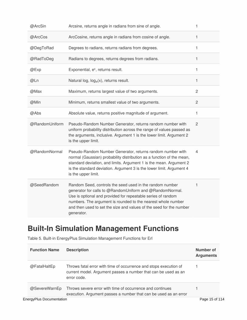
@ArcSin Arcsine, returns angle in radians from sine of angle. 1
@ArcCos ArcCosine, returns angle in radians from cosine of angle. 1
@DegToRad Degrees to radians, returns radians from degrees. 1
@RadToDeg Radians to degrees, returns degrees from radians. 1
@Exp Exponential, e , returns result. 1
@Ln Natural log, log (x), returns result. 1
@Max Maximum, returns largest value of two arguments. 2
@Min Minimum, returns smallest value of two arguments. 2
@Abs Absolute value, returns positive magnitude of argument. 1
@RandomUniform Pseudo-Random Number Generator, returns random number withuniform probability distribution across the range of values passed asthe arguments, inclusive. Argument 1 is the lower limit. Argument 2is the upper limit.
2
@RandomNormal Pseudo-Random Number Generator, returns random number withnormal (Gaussian) probability distribution as a function of the mean,standard deviation, and limits. Argument 1 is the mean. Argument 2is the standard deviation. Argument 3 is the lower limit. Argument 4is the upper limit.
4
@SeedRandom Random Seed, controls the seed used in the random numbergenerator for calls to @RandomUniform and @RandomNormal. Use is optional and provided for repeatable series of randomnumbers. The argument is rounded to the nearest whole numberand then used to set the size and values of the seed for the numbergenerator.
1
Built-In Simulation Management FunctionsTable 5. Built-in EnergyPlus Simulation Management Functions for Erl
Function Name Description Number ofArguments
@FatalHaltEp Throws fatal error with time of occurrence and stops execution ofcurrent model. Argument passes a number that can be used as anerror code.
1
@SevereWarnEp Throws severe error with time of occurrence and continuesexecution. Argument passes a number that can be used as an error
1
x
e
EnergyPlus Documentation Page 15 of 114

code.
@WarnEp Throws warning error and continues execution. Argument passes anumber that can be used as an error code.
1
Built-in Trend Variable FunctionsFor control algorithms, you often need to be able put a sensor reading into some historical context. Thetrend variables are provided in Erl as a way to log the time history of data to use in control decisions. Touse the trend variables in Erl programs, their values must be extracted and placed into normal Erl variables.Setting up an Erl variable as a trend variable requires an EnergyManagementSystem:TrendVariable inputobject. The access functions listed in Table 6 are used to obtain data from a trend variable during theexecution of an Erl program. These functions act on trend variables and return values into the user’s Erlvariables for subsequent use in calculations. Each trend function takes the name of the trend variable andan index that identifies how far back in time the function should be applied. Trend variable names are alsoErl variables but with special pointers to another data structure with the time series data storage. The trendlogs have a first-in, first-out storage array where only the most recent data are retained. Each element inthe history corresponds to the result for that value over a zone timestep. The time difference between trendlog items is the zone timestep in hours, so that the slope returned by @TrendDirection is in per-hour units.
Table 6. Built-in Functions for Trend Variables in Erl
Function Name Description Number ofArguments
@TrendValue Returns history value for a particular number of timesteps into thepast. Dereferences data stored in trend into another Erl variable.Takes trend variable name and the specific timestep into the past toreturn.
2
@TrendAverage Returns historical average (mean) for values in trend variable. Takestrend variable name and number of steps into the past to analyze
2
@TrendMax Returns historical maximum for values in trend variable. Takes trendvariable name and number of steps into the past to analyze.
2
@TrendMin Returns historical minimum for values in trend variable within theindex. Takes trend variable name and number of steps into the past toanalyze.
2
@TrendDirection Returns slope of a linear least squares fit of trend data within theindex. Positive if trend is increasing, negative if decreasing. Takestrend variable name and number of steps into the past to analyze.
2
@TrendSum Returns sum of elements stored in trend. Takes trend variable nameand number of steps into the past to analyze.
2
The trend functions all take as their second argument an array index. This number should be considered an
EnergyPlus Documentation Page 16 of 114
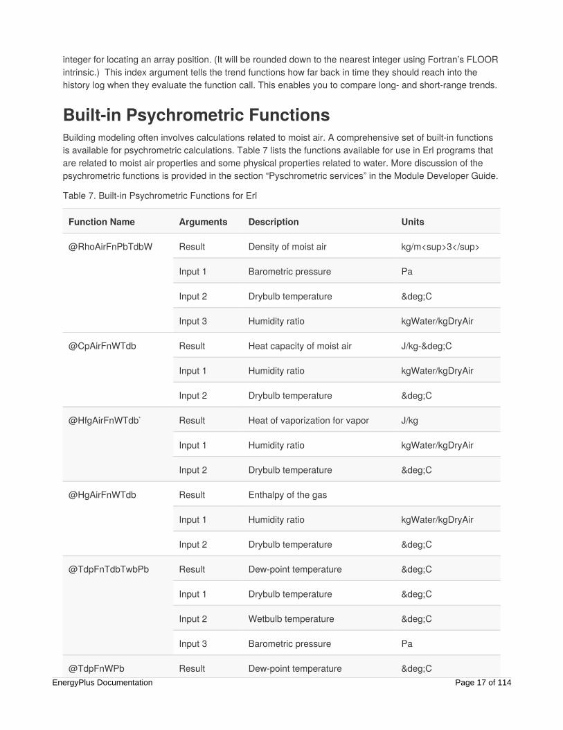
integer for locating an array position. (It will be rounded down to the nearest integer using Fortran’s FLOORintrinsic.) This index argument tells the trend functions how far back in time they should reach into thehistory log when they evaluate the function call. This enables you to compare long- and short-range trends.
Built-in Psychrometric FunctionsBuilding modeling often involves calculations related to moist air. A comprehensive set of built-in functionsis available for psychrometric calculations. Table 7 lists the functions available for use in Erl programs thatare related to moist air properties and some physical properties related to water. More discussion of thepsychrometric functions is provided in the section “Pyschrometric services” in the Module Developer Guide.
Table 7. Built-in Psychrometric Functions for Erl
Function Name Arguments Description Units
@RhoAirFnPbTdbW Result Density of moist air kg/m<sup>3</sup>
Input 1 Barometric pressure Pa
Input 2 Drybulb temperature °C
Input 3 Humidity ratio kgWater/kgDryAir
@CpAirFnWTdb Result Heat capacity of moist air J/kg-°C
Input 1 Humidity ratio kgWater/kgDryAir
Input 2 Drybulb temperature °C
@HfgAirFnWTdb` Result Heat of vaporization for vapor J/kg
Input 1 Humidity ratio kgWater/kgDryAir
Input 2 Drybulb temperature °C
@HgAirFnWTdb Result Enthalpy of the gas
Input 1 Humidity ratio kgWater/kgDryAir
Input 2 Drybulb temperature °C
@TdpFnTdbTwbPb Result Dew-point temperature °C
Input 1 Drybulb temperature °C
Input 2 Wetbulb temperature °C
Input 3 Barometric pressure Pa
@TdpFnWPb Result Dew-point temperature °CEnergyPlus Documentation Page 17 of 114

Input 1 Humidity ratio kgWater/kgDryAir
Input 2 Barometric pressure Pa
@HFnTdbW Result Enthalpy of moist air J/kg
Input 1 Drybulb temperature °C
Input 2 Humidity ratio kgWater/kgDryAir
@HFnTdbRhPb Result Enthalpy of moist air J/kg
Input 1 Drybulb temperature °C
Input 2 Relative humidity Fraction (0.0 .. 1)
Input 3 Barometric pressure Pa
@TdbFnHW Result Drybulb temperature °C
Input 1 Enthalpy of moist air J/kg
Input 2 Humidity ratio kgWater/kgDryAir
@RhovFnTdbRh Result Vapor density in air kg/m<sup>3</sup>
Input 1 Drybulb temperature °C
Input 2 Relative humidity Fraction (0.0 .. 1)
@RhovFnTdbWPb Result Vapor density in air kg/m<sup>3</sup>
Input 1 Drybulb temperature °C
Input 2 Humidity ratio kgWater/kgDryAir
Input 3 Barometric pressure Pa
@RhFnTdbRhov Result Relative humidity Fraction (0.0 .. 1)
Input 1 Drybulb temperature °C
Input 2 Vapor density in air kg/m<sup>3</sup>
@RhFnTdbWPb Result Relative humidity Fraction (0.0 .. 1)
Input 1 Drybulb temperature °C
Input 2 Humidity ratio kgWater/kgDryAir
EnergyPlus Documentation Page 18 of 114

Input 3 Barometric pressure Pa
@TwbFnTdbWPb Result Wetbulb temperature °C
Input 1 Drybulb temperature °C
Input 2 Humidity ratio kgWater/kgDryAir
Input 3 Barometric pressure Pa
@VFnTdbWPb Result Specific volume m<sup>3</sup>/kg
Input 1 Drybulb temperature °C
Input 2 Humidity ratio kgWater/kgDryAir
Input 3 Barometric pressure Pa
@WFnTdpPb Result Humidity ratio kgWater/kgDryAir
Input 1 Dew-point temperature °C
Input 2 Barometric pressure Pa
@WFnTdbH Result Humidity ratio kgWater/kgDryAir
Input 1 Drybulb temperature °C
Input 2 Enthalpy of moist air J/kg
@WFnTdbTwbPb Result Humidity ratio kgWater/kgDryAir
Input 1 Drybulb temperature °C
Input 2 Wetbulb temperature °C
Input 3 Barometric pressure Pa
@WFnTdbRhPb Result Humidity ratio kgWater/kgDryAir
Input 1 Drybulb temperature °C
Input 2 Relative humidity Fraction (0.0 .. 1)
Input 3 Barometric pressure Pa
@PsatFnTemp Result Saturation pressure Pa
Input 1 Drybulb temperature °C
EnergyPlus Documentation Page 19 of 114
@TsatFnHPb Result Saturation temperature °C
Input 1 Enthalpy of moist air J/kg
Input 2 Barometric pressure Pa
@CpCW Result Heat capacity of water J/kg
Input 1 Temperature °C
@CpHW Result Heat capacity of water J/kg
Input 1 Temperature °C
@RhoH2O Result Density of water kg/m<sup>3</sup>
Input 1 Temperature °C
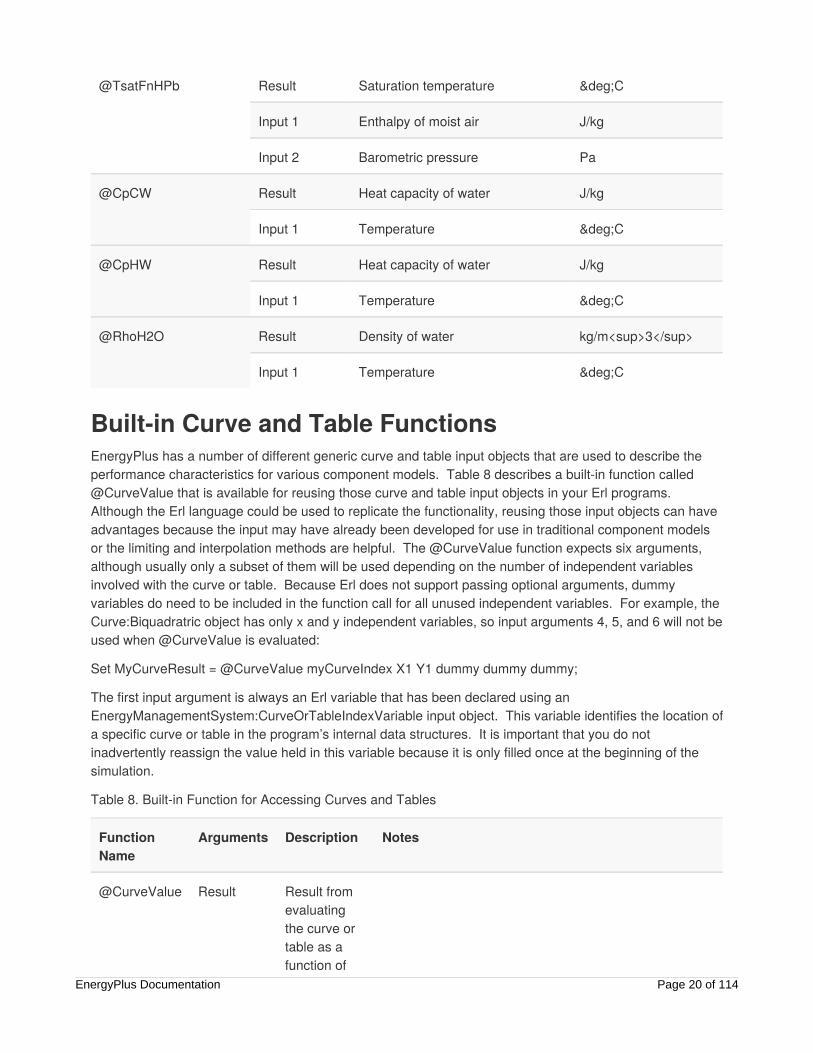
Built-in Curve and Table FunctionsEnergyPlus has a number of different generic curve and table input objects that are used to describe theperformance characteristics for various component models. Table 8 describes a built-in function called@CurveValue that is available for reusing those curve and table input objects in your Erl programs. Although the Erl language could be used to replicate the functionality, reusing those input objects can haveadvantages because the input may have already been developed for use in traditional component modelsor the limiting and interpolation methods are helpful. The @CurveValue function expects six arguments,although usually only a subset of them will be used depending on the number of independent variablesinvolved with the curve or table. Because Erl does not support passing optional arguments, dummyvariables do need to be included in the function call for all unused independent variables. For example, theCurve:Biquadratric object has only x and y independent variables, so input arguments 4, 5, and 6 will not beused when @CurveValue is evaluated:
Set MyCurveResult = @CurveValue myCurveIndex X1 Y1 dummy dummy dummy;
The first input argument is always an Erl variable that has been declared using anEnergyManagementSystem:CurveOrTableIndexVariable input object. This variable identifies the location ofa specific curve or table in the program’s internal data structures. It is important that you do notinadvertently reassign the value held in this variable because it is only filled once at the beginning of thesimulation.
Table 8. Built-in Function for Accessing Curves and Tables
FunctionName
Arguments Description Notes
@CurveValue Result Result fromevaluatingthe curve ortable as afunction of
EnergyPlus Documentation Page 20 of 114
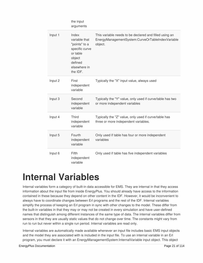
the inputarguments
Input 1 Indexvariable that"points" to aspecific curveor tableobjectdefinedelsewhere inthe IDF.
This variable needs to be declared and filled using anEnergyManagementSystem:CurveOrTableIndexVariableobject.
Input 2 Firstindependentvariable
Typically the "X" input value, always used
Input 3 Secondindependentvariable
Typically the "Y" value, only used if curve/table has twoor more independent variables
Input 4 Thirdindependentvariable
Typically the "Z" value, only used if curve/table hasthree or more independent variables.
Input 5 Fourthindependentvariable
Only used if table has four or more independentvariables
Input 6 Fifthindependentvariable
Only used if table has five independent variables
Internal VariablesInternal variables form a category of built-in data accessible for EMS. They are internal in that they accessinformation about the input file from inside EnergyPlus. You should already have access to the informationcontained in these because they depend on other content in the IDF. However, it would be inconvenient toalways have to coordinate changes between Erl programs and the rest of the IDF. Internal variablessimplify the process of keeping an Erl program in sync with other changes to the model. These differ fromthe built-in variables in that they may or may not be created in every simulation and have user-definednames that distinguish among different instances of the same type of data. The internal variables differ fromsensors in that they are usually static values that do not change over time. The constants might vary fromrun to run but never within a single run period. Internal variables are read only.
Internal variables are automatically made available whenever an input file includes basic EMS input objectsand the model they are associated with is included in the input file. To use an internal variable in an Erlprogram, you must declare it with an EnergyManagementSystem:InternalVariable input object. This object
EnergyPlus Documentation Page 21 of 114

assigns a specified Erl variable name to contain the value in an internal EnergyPlus data structure. TheEDD file lists the specific internal variable types, their unique identifying names, and the units. The rest ofthis section provides information about specific internal variables.
Zone GeometryThe internal variables called “Zone Air Volume” and “Zone Floor Area” provide basic geometric informationabout each zone. EnergyPlus calculates these from the geometry in the IDF, or you may input the zone airvolume in the zone input object. These internal variables in Erl programming should be useful during aparametric study where the shape of the building is being varied, as for a massing study. For example, youcould use the zone floor area to normalize Erl calculations with a per-unit area. Or you could use the zoneair volume to convert between air flows in m /s to air changes per hour (ACH).
The internal variables called “Zone Multiplier” and “Zone List Multiplier” indicate the multipliers assigned tozones. These can be useful for customizing sizing calculations.
Internal GainsA number of internal variables describe design levels for the various types of internal gains.
People Count Design LevelThe internal variable “People Count Design Level” provides information about the maximum number ofpeople associated with each people input object. The units are number of people. This is the value enteredin, or resulting from intermediate calculations using, the inputs in the People object. This variable is usefulfor scaling the values assigned to the “Number of People” control in the “People” EMS actuator.
Lighting Power Design LevelThe internal variable “Lighting Power Design Level” provides information about the maximum lightingelectrical power level associated with each Lights input object. The units are Watts. This is the valueentered in, or resulting from intermediate calculations using, the inputs in the lights object. This variable isuseful for scaling the values assigned to the “Electric Power Level control in the “Lights” EMS actuator.
Plug and Process Power Design LevelThe internal variable “Plug and Process Power Design Level” provides information about the maximumelectrical equipment power level associated with each ElectricEquipment input object. The units are Watts.This is the value entered in, or resulting from intermediate calculations using, the inputs in theElectricEquipment object. This variable is useful for scaling the values assigned to the “Electric PowerLevel” control in the “ElectricEquipment” EMS actuator.
Gas Process Power Design LevelThe internal variable “Gas Process Power Design Level” provides information about the maximum gasequipment power level associated with each GasEquipment input object. The units are Watts. This is thevalue entered in, or resulting from intermediate calculations using, the inputs in the GasEquipment object.
3
EnergyPlus Documentation Page 22 of 114

This variable is useful for scaling the values assigned to the “Gas Power Level” control in the“GasEquipment” EMS actuator.
Process District Heat Design LevelThe internal variable “Process District Heat Design Level” provides information about the maximum districtheating power level associated with each HotWaterEquipment input object. The units are Watts. This is thevalue entered in, or resulting from intermediate calculations using, the inputs in the HotWaterEquipmentobject. This variable is useful for scaling the values assigned to the “District Heating Power Level” control inthe “HotWaterEquipment” EMS actuator.
Process Steam District Heat Design LevelThe internal variable “Process Steam District Heat Design Level” provides information about the maximumdistrict heating power level associated with each SteamEquipment input object. The units are Watts. This isthe value entered in, or resulting from intermediate calculations using, the inputs in the SteamEquipmentobject. This variable is useful for scaling the values assigned to the “District Heating Power Level” control inthe “SteamEquipment” EMS actuator.
Other Equipment Design LevelThe internal variable “Other Equipment Design Level” provides information about the maximum power levelassociated with each OtherEquipment input object. The units are Watts. This is the value entered in, orresulting from intermediate calculations using, the inputs in the OtherEquipment object. This variable isuseful for scaling the values assigned to the “Power Level” control in the “OtherEquipment” EMS actuator.
Simple Zone Baseboard CapacityThe internal variables called “Simple Zone Baseboard Capacity At Low Temperature” and “Simple ZoneBaseboard Capacity At High Temperature” provide information about the power levels associated with eachZoneBaseboard:OutdoorTemperatureControlled object. These value are inputs to that object. The variablesare useful for scaling the values assigned to the “Power Level” control in the“ZoneBaseboard:OutdoorTemperatureControlled” EMS actuator.
HVAC SystemsAirTerminal:SingleDuct:UncontrolledAn internal variable called “AirTerminal:SingleDuct:Uncontrolled Maximum Mass Flow Rate” providesinformation about the design flow rate for direct air terminals. The units are kg/s. This is the mass flow rate(for dry air at standard conditions) at the volume flow rate entered in the field Maximum Air Flow Rate (m /s)in the AirTerminal:SingleDuct:Uncontrolled input object. This internal variable is useful for scaling the flowrates assigned to the “Mass Flow Rate” control in the “AirTerminal:SingleDuct:Uncontrolled” EMS actuator.
Fan Nominal RatingsFan Maximum Mass Flow Rate
3
EnergyPlus Documentation Page 23 of 114

The input variable “Fan Maximum Mass Flow Rate” provides information about the maximum flow rate for afan. The units are kg/s. This is the mass flow rate (for dry air at standard conditions) associated with thevolume flow rate entered into the Maximum Air Flow Rate (m /s) in the various fan input objects. Thisinternal variable is useful for scaling the flow rates assigned to the “Fan Air Mass Flow Rate” control in the“Fan” EMS actuator.
Fan Nominal Pressure RiseThe input variable “Fan Nominal Pressure Rise” provides information about the static pressure riseexperienced by a fan. The units are Pascals. This is the value entered into the field called Pressure Rise inthe various fan input objects. This internal variable is useful for scaling the pressures assigned to the “FanPressure Rise” control in the “Fan” EMS actuator.
Fan Nominal Total EfficiencyThe input variable “Fan Nominal Total Efficiency” provides information about the nominal efficiency of eachfan. The value is dimensionless and expressed as a fraction. This is the value entered into the field calledFan Efficiency in the various fan input objects. This internal variable is useful for scaling the value assignedto “Fan Total Efficiency” control in the “Fan” EMS actuator.
Unitary HVAC Nominal RatingsUnitary HVAC Design Heating CapacityThe internal variable called “Unitary HVAC Design Heating Capacity” provides information about thenominal heating capacity of unitary or furnace HVAC equipment. The units are Watts. The source of thesedata will vary depending on the type of heating coil. This internal variable is useful for scaling the valueassigned to “Sensible Load Request” control in the “Unitary HVAC” EMS actuator.
Unitary HVAC Design Cooling CapacityThe internal variable called “Unitary HVAC Design Cooling Capacity” provides information about thenominal cooling capacity of unitary or furnace HVAC equipment. The units are Watts. The source of thesedata will vary depending on the type of cooling coil. This internal variable is useful for scaling the valueassigned to “Sensible Load Request” control in the “Unitary HVAC” EMS actuator.
Outdoor Air Mixer Nominal RatingsOutdoor Air Controller Maximum Mass Flow RateThe internal variable called “Outdoor Air Controller Maximum Mass Flow Rate” provides information aboutthe maximum outdoor air rate for each outdoor air system. The units are kg/s. The sources of these dataare inputs in the Controller:OutdoorAir input object. This internal variable is useful for scaling the valueassigned to the “Air Mass Flow Rate” control in the “Outdoor Air Controller” EMS actuator.
Outdoor Air Controller Minimum Mass Flow RateThe internal variable called “Outdoor Air Controller Minimum Mass Flow Rate” provides information aboutthe minimum outdoor air rate for each outdoor air system. The units are kg/s. The sources of these data areinputs in the Controller:OutdoorAir input object. This internal variable is useful for scaling the valueassigned to the “Air Mass Flow Rate” control in the “Outdoor Air Controller” EMS actuator.
3
EnergyPlus Documentation Page 24 of 114

Pump Nominal RatingsThe internal variable called “Pump Maximum Mass Flow Rate” provides information about the size of thepump. The units are kg/s. This is the mass flow rate associated with the volume flow rate entered into theRated Flow Rate (m /s) in the various pump input objects. This internal variable is useful for scaling the flowrates assigned to the “Pump Mass Flow Rate” control in the “Pump” EMS actuator.
Low Temperature Radiant HydronicConstant Flow Low Temp Radiant Design Water Mass Flow RateThe internal variable called “Constant Flow Low Temp Radiant Design Water Mass Flow Rate” providesinformation about the design water flow rate for radiant systems defined using aZoneHVAC:LowTemperatureRadiant:ConstantFlow input object. The units are m /s. This internal variable isuseful for scaling the flow rates assigned to the “Water Mass Flow Rate” control in the “Constant Flow LowTemp Radiant” EMS actuator.
Hydronic Low Temp Radiant Design Water Mass Flow Rate for HeatingThe internal variable called “Hydronic Low Temp Radiant Design Water Mass Flow Rate for Heating”provides information about the heating design water flow rate for radiant systems defined using aZoneHVAC:LowTemperatureRadiant:VariableFlow input object. The units are m /s. This internal variable isuseful for scaling the flow rates assigned to the “Water Mass Flow Rate” control in the “Hydronic Low TempRadiant” EMS actuator.
Hydronic Low Temp Radiant Design Water Mass Flow Rate for CoolingThe internal variable called “Hydronic Low Temp Radiant Design Water Mass Flow Rate for Heating”provides information about the cooling design water flow rate for radiant systems defined using aZoneHVAC:LowTemperatureRadiant:VariableFlow input object. The units are m /s. This internal variable isuseful for scaling the flow rates assigned to the “Water Mass Flow Rate” control in the “Hydronic Low TempRadiant” EMS actuator.
On-Site Electricity ProductionGenerator Nominal RatingsThe internal variables called “Generator Nominal Maximum Power” and “Generator Nominal Thermal ToElectric Power” provide information about the nominal capacity of a generator to produce electricity andheat. The values made available here are those listed in the associated ElectricLoadCenter:Generatorsinput object. The power is expressed in Watts.
The thermal-to-electric ratio describes how the nominal thermal output compares to the nominal electricaloutput and is useful for characterizing combined heat and power (CHP) units.
Electrical StorageThe internal variable called “Electrical Storage Maximum Capacity” provides information about the capacityof electrical storage devices. This is the value of the field called Maximum Storage Capacity in the
3
3
3
3
EnergyPlus Documentation Page 25 of 114

ElectricLoadCenter:Storage:Simple input object. The units are in Joules.
SizingSeveral internal variables relate to sizing calculations. Although the primary intent for the EMS is to enablecustom controls for operation, using internal variables is a prime example of extending the power of user-defined calculations to control certain aspects of sizing calculations.
Sizing:ZoneA series of internal variables is available related to zone sizing:
Final Zone Design Heating Air Mass Flow Rate (kg/s)
Intermediate Zone Design Heating Air Mass Flow Rate (kg/s)
Final Zone Design Cooling Air Mass Flow Rate (kg/s)
Intermediate Zone Design Cooling Air Mass Flow Rate (kg/s)
Final Zone Design Heating Load (W)
Intermediate Zone Design Heating Load (W)
Final Zone Design Cooling Load (W)
Intermediate Zone Design Cooling Load (W)
Final Zone Design Heating Air Density (kg/m )
Intermediate Zone Design Heating Air Density (kg/m )
Final Zone Design Cooling Air Density (kg/m )
Intermediate Zone Design Cooling Air Density (kg/m )
Final Zone Design Heating Volume Flow (m3/s)
Intermediate Zone Design Heating Volume Flow (m3/s)
Final Zone Design Cooling Volume Flow (m3/s)
Intermediate Zone Design Cooling Volume Flow (m3/s)
Zone Outdoor Air Design Volume Flow Rate (m /s)
Sizing:SystemA series of internal variables is available related to air system sizing:
Intermediate Air System Main Supply Volume Flow Rate (m /s)
Intermediate Air System Coincident Peak Cooling Mass Flow Rate (kg/s)
Intermediate Air System Coincident Peak Heating Mass Flow Rate (kg/s)
Intermediate Air System Noncoincident Peak Cooling Mass Flow Rate (kg/s)
3
3
3
3
3
3
EnergyPlus Documentation Page 26 of 114

Intermediate Air System Noncoincident Peak Heating Mass Flow Rate (kg/s)
Intermediate Air System Heating Volume Flow Rate (m /s)
Intermediate Air System Cooling Volume Flow Rate (m /s)
Air System Cooling Design Sensible Capacity (W)
Air System Heating Design Sensible Capacity (W)
Air System Preheating Design Sensible Capacity (W)
Air System Outdoor Air Design Volume Flow Rate (m /s)
Air System Cooling Design Mixed Air Temperature (C)
Air System Cooling Design Mixed Air Humidity Ratio (kgWater/kgDryAir)
Air System Cooling Design Return Air Temperature (C)
Air System Cooling Design Return Air Humidity Ratio (kgWater/kgDryAir)
Air System Cooling Design Outdoor Air Temperature (C)
Air System Cooling Design Outdoor Air Humidity Ratio (kgWater/kgDryAir)
Air System Heating Design Mixed Air Temperature (C)
Air System Heating Design Mixed Air Humidity Ratio (kgWater/kgDryAir)
Air System Heating Design Return Air Temperature (C)
Air System Heating Design Return Air Humidity Ratio (kgWater/kgDryAir)
Air System Heating Design Outdoor Air Temperature (C)
Air System Heating Design Outdoor Air Humidity Ratio (kgWater/kgDryAir)
Sizing:PlantAn internal variable is available for plant system sizing.
Plant Design Volume Flow Rate (m /s)
EMS SensorsThis section provides more information about EMS sensors.
The input object EnergyManagementSystem:Sensor is simple but quite powerful. It reuses the normalEnergyPlus output variables to provide a general way of obtaining a wide variety of input data with minimalcomplications.
One odd result of the approach taken for EMS sensors is that information about the available sensors isderived from what are usually the outputs of EnergyPlus. The RDD file is an important resource for EMSusers. The RDD file is an output from running EnergyPlus and is called “eplusout.rdd” (but you may renameit to <your-filename>.rdd with a run manager such as EP-Launch). This output file is often needed todevelop EMS input, so you may need to do an initial run of the model with traditional controls to obtain an
3
3
3
3
EnergyPlus Documentation Page 27 of 114
RDD file. The contents of an RDD file will vary depending on the type of model. Once you have experienceand familiarity with the outputs expected from a model, you should not need to prerun models, as you willbe able to foresee the available output. The RDD file from a similar model with the same types ofcomponents and systems can also be used as a guide for what will be available in a specific model.
Variable TypesVarious types of output variables in EnergyPlus can be used as sensors in the EMS. It is important tounderstand some distinctions.
Reported variables have two update frequencies: zone and system. Zone variables are updated foreach zone timestep. System variables are updated for each system timestep.
Reported variables have two types of content: averaged and summed. Averaged variables arestate variables such as temperature and mass flow rate. Summed variables are quantities of energysuch as electricity use.
SchedulesThe EnergyManagementSystem:Sensor object can also provide scheduled data for use in Erl programs.Because schedule values are available as outputs that use the “Schedule Value” output, they can also bemapped as sensors. You can use any of the various types of schedule input objects to define a schedule.The schedule does not need to be used elsewhere in the model. The value of the schedule is then mappedto an EMS variable with the Schedule Value report variable. When used with the Schedule:File inputobject, the sensor object can import time series data into the EMS from an external file. One applicationmight be to test a proposed EMS algorithm with real experimental data.
EMS ActuatorsThis section provides details about EMS actuators, the conduits by which Erl programs control EnergyPlussimulations. They actuate selected features inside EnergyPlus. Rather than add a new set of controls andcomponent models that have EMS awareness, they generally override established features.
Internal to EnergyPlus are two separate lists of actuators: those that are available for use, and those thatare being used in the EMS. While implementing the EMS, developers have added code to control points tomake them available for use in EMS. The actuators available in a given model depend on the non-EMS-related content of the input file. Similar to how EnergyPlus reports the available output variables to the RDDfile, a list of available actuators is written to the EDD file (depending on the settings inOutput:EnergyManagementSystem). Note that the EDD file is ONLY produced if you have set up EMS / Erlprograms. To use an actuator in EMS, you need to enter an EnergyManagementSystem:Actuator inputobject. The EDD file contains information needed for this input object; however, it is not available until afterthe output has been generated from a previous run. If you do not see a particular actuator in the EDDoutput file, it is not available in EMS for that particular model. There is no way to create a new actuator(except by modifying EnergyPlus source code); you can only customize the behavior of current actuators. Ifyou need an actuator that you suspect could be provided by the program but is not available, you can usethe regular system(s) for user support to request it be added to the program. New actuators are added tothe program from time to time so the availability of actuators will grow with each new release.
EnergyPlus Documentation Page 28 of 114

Actuators override things inside EnergyPlus whenever the actuator’s Erl variable is set to a value other than“Null.” Null is a special built-in variable used to deactivate an actuator. Once an actuator starts overriding, itwill continue to do so until the actuator’s Erl variable is set to Null. You should set the actuators to Nullwhenever you want the EMS to revert to normal operation.
The rest of this section provides details about specific actuators.
HVAC SystemsSystem Node SetpointsA series of actuators is available for all the setpoints that can be placed on system nodes. System nodesare used to define air and plant loops, and a natural application of EMS is to control the setpoints at thesenodes. The node actuators are all called “System Node Setpoint.” There are nine control types:
Temperature Setpoint, (°C)
Temperature Minimum Setpoint (°C)
Temperature Maximum Setpoint (°C)
Humidity Ratio Setpoint (kgWater/kgDryAir)
Humidity Ratio Minimum Setpoint (kgWater/kgDryAir)
Humidity Ratio Maximum Setpoint (kgWater/kgDryAir)
Mass Flow Rate Setpoint (kg/s)
Mass Flow Rate Minimum Setpoint (kg/s)
Mass Flow Rate Maximum Setpoint (units kg/s)
Using these actuators is natural with an EMS. Typically, the controller would place the setpoint on the outletnode. Then the component’s low-level controller should operate to meet the leaving setpoint. Setting thesetpoints on nodes should be a common application for the EMS.
Although all nine possible setpoints are available as EMS actuators, it does not follow that EnergyPlus canuse all of them. Most components can use only one or two setpoints. If a component cannot control to meetthe setpoints on a node, the actuator will do nothing.
Zone HVAC ControlSeveral actuators relate to HVAC zone controls for temperature, humidity, and comfort.
Two actuators called “Zone Temperature Control” are available with the control types of “HeatingSetpoint” and “Cooling Setpoint.” These enable you to directly override the zone-by-zone heatingand cooling setpoints. The units are in degrees Celsius. The unique identifier is the zone name.
Two actuators called “Zone Humidity Control” are available with the control types “Relative HumidityHumidifying Setpoint” and “Relative Humidity Dehumidifying Setpoint.” These enable you to directlyoverride the zone-by-zone humidity control setpoints. The units are in percent relative humidity. Theunique identifier is the zone name.
EnergyPlus Documentation Page 29 of 114

Two actuators called “Zone Comfort Control” are available with the control types “Heating Setpoint”and “Cooling Setpoint.” These enable you to directly override the zone-by-zone comfort controlsetpoints. The units are predicted mean vote (PMV). The unique identifier is the zone name.
Plant Supervisory ControlSeveral levels of actuators are available for on/off supervisory control of Plant systems.
Each plant (and condenser) loop has an actuator called “Plant Loop Overall” available with thecontrol type “On/Off Supervisory.” Setting the value of this actuator to 1.0 directs the overall plant toloop to run normally based on other controls. Setting the value of this actuator to 0.0 directs theoverall plant loop to shut down regardless of what other controls indicate.
Each plant (and condenser) loop has actuators called “Supply Side Half Loop” and “Demand SideHalf Loop” that are available with the control type “On/Off Supervisory.” Setting the value of thisactuator to 1.0 directs the plant’s loop side to run normally based on other controls. Setting the valueof this actuator to 0.0 directs the plant’s loop side to shut down regardless of what other controlsindicate.
Each plant (and condenser) loop has a series of actuators called “Supply Side Branch” and“Demand Side Branch” that are available with the control type “On/Off Supervisory.” These areavailable for each individual branch in a loop. Setting the value of this actuator to 1.0 directs theplant’s branch to run normally based on other controls. Setting the value of this actuator to 0.0directs the plant’s branch to shut down regardless of what other controls indicate.
Each plant (and condenser) loop has a series of actuators called “Plant Component *” that areavailable with the control type “On/Off Supervisory.” These are available for each individualcomponent on a loop. Setting the value of this actuator to 1.0 directs the component to run normallybased on other controls. Setting the value of this actuator to 0.0 directs the component to shut downregardless of what other controls indicate.
Outdoor Air System Node ConditionsActuators called “Outdoor Air System Node” are available with control types called “Drybulb Temperature”and “Wetbulb Temperature.” The units are degrees Celsius. These actuators are available for all systemnodes that are listed in either an OutdoorAir:Node or OutdoorAir:NodeList input object. You should probablyset both the drybulb and wetbulb temperatures to ensure a full description of the moist air conditions.
The air system and many component models require you to specify a node as an outdoor air node to obtainvalues for the outdoor conditions. For example, outdoor air nodes are used at the inlet to an outdoor airmixer or at the inlet of the heat rejection side of a component model. Typically this is the weather data valuefor outdoor conditions. But local variations in microclimate may shift the local outdoor air temperature todiffer slightly from the weather data. (Currently the only local variation model for this effect in EnergyPlusvaries the outdoor air conditions as a function of height.) If you want to experiment with other models forlocal variations in outdoor air conditions, this EMS actuator allows you to override the outdoor temperatureat a particular system node with any model that can be implemented in an Erl program. For example(although better models for the changes in conditions may need be developed), this actuator could be usedto examine the energy impacts of warmer outdoor air temperatures experienced by a rooftop packagedHVAC system sitting on a black roof or the cooler conditions experienced by a unit that is located on theshaded side of a building. Another example is to make use of a separate model, outside of EnergyPlus, for
EnergyPlus Documentation Page 30 of 114
some unique type of component (such as a labyrinth or earth-tube) that preconditions outdoor air; theresults of that model could be fed into the air system model in EnergyPlus using these actuators.
AirLoopHVAC Availability StatusThis actuator is available in all models with central, or primary, air systems that are entered with the object“AirLoopHVAC.” Various availability managers use the air loop’s availability status to override control of thecentral air system fan. The fan may be scheduled to be unavailable during certain times to shut down thesystem when it is not needed. However, there may be times when the air system should be started toprotect from freezing, for example. This actuator can force an air system to start up or shut down.
The control is actuated by setting values for the availability status. The settings are numeric, but representdiscrete states the status can take. The following settings are valid:
0.0 (= NoAction). This tells the air system to do whatever it would usually do without any specialoverride status.
1.0 (= ForceOff). This overrides the air system to shut down when it would normally want to run.
2.0 (= CycleOn). This overrides the air system to start up when it would normally be off.
3.0 (= CycleOnZoneFansOnly). This overrides only the zone fans (not the central fans) if they wouldnormally be off.
Ideal Loads Air SystemAn actuator called “Ideal Loads Air System” is available with control types called “Air Mass Flow Rate”(supply air), “Outdoor Air Mass Flow Rate,” “Air Temperature,” and “Air Humidity Ratio.” These areavailable in models that use the ideal loads air system, formerly known as purchased air. The units are kg/sfor mass flow rate, C for temperature and kgWater/kgDryAir for humidity ratio. The unique identifier is theuser-defined name of the ZoneHVAC:IdealLoadsAirSystem input object.
For Air Temperature and Air Humidity Ratio, the overrides are absolute. They are applied after all otherlimits have been checked. For mass flow rate, the overrides are not absolute, in that the model hasadditional internal controls that may not always be overridden. The internal controls will still apply thecapacity and flow rate limits if defined in the input object. The EMS override affects the flow rate only if theair system is on. If the air system is “off,” the mass flow is zero regardless of the actuator setting. Theinternal model controls will turn off the air system if the zone is in the dead band or if it is scheduled “off” byavailability managers. This behavior allows you to use the internal controls to determine when the airshould cycle on, as for a constant volume system that cycles to achieve control. If both the Air Mass FlowRate and Outdoor Air Mass Flow Rate are overridden, the Outdoor Air Mass Flow Rate will not be allowedto be greater than the override value for Air Mass Flow Rate.
FanActuators called “Fan” are available with the control types “Fan Air Mass Flow Rate,” “Fan Pressure Rise,”and “Fan Total Efficiency.” These provide direct control over the fan operation in an air system. The EMSprogram can override the flow rate by using kg/s. It can override the total pressure rise at the fan by usingPascals. And it can override the fan efficiency on a scale from 0.0 to 1.0. The unique identifier is the nameof the fan in the Fan input objects.
EnergyPlus Documentation Page 31 of 114

An actuator is also available for overriding the autosize value for the fan’s design air flow rate. Thisactuator is called “Fan” and the control type is “'Fan Autosized Air Flow Rate” with units in m /s. It is onlyuseful from the calling point named AfterComponentInputReadIn.
DX Cooling CoilsActuators are available for overriding the autosize values related to the size of single speed DX coils. Actuators called “Coil:Cooling:DX:SingleSpeed” are available with control types “Autosized Rated Air FlowRate” (in m3/s), “Autosized Rated Sensible Heat Ratio” (in W/W), and “Autosized Rated Total CoolingCapacity” (in W). These are only useful from the calling point named AfterComponentInputReadIn.
Unitary EquipmentActuators called “Unitary HVAC” are available with the control types “Sensible Load Request” and“Moisture Load Request.” These control the operation of unitary equipment. Normally these systemsoperate to meet zone loads, but these actuators allow you to override the controls of unitary systems. Theunits are in Watts. The unique identifier is the name of the unitary equipment in the input objects.
Actuators are available for overriding the autosize values related to supply air flow rates some unitaryHVAC equipment. These actuators allow selectively altering the outcome of sizing routines and are usedfrom the calling point named AfterComponentInputReadIn. The units are m /s.
An actuator called “AirLoopHVAC:Unitary:Furnace:HeatOnly” is available with control type“Autosized Supply Air Flow Rate.”
An actuator called “AirLoopHVAC:UnitaryHeatOnly” is available with control type “Autosized SupplyAir Flow Rate.”
Actuators called “AirLoopHVAC:Unitary:Furnace:HeatCool” and “AirLoopHVAC:UnitaryHeatCool”areavailable with control types “Autosized Supply Air Flow Rate,” “Autosized Supply Air Flow RateDuring Cooling Operation,” “Autosized Supply Air Flow Rate During Heating Operation,” and“Autosized Supply Air Flow Rate During No Heating or Cooling Operation.”
An actuator called “AirLoopHVAC:UnitaryHeatPump:AirToAir” is available with control type“Autosized Supply Air Flow Rate.”
An actuator called “AirLoopHVAC:UnitaryHeatPump:WaterToAir” is available with control type“Autosized Supply Air Flow Rate.”
AirTerminal:SingleDuct:UncontrolledAn actuator called “AirTerminal:SingleDuct:Uncontrolled” is available with a control type called “Mass FlowRate.” This actuator is available in models that use the direct air terminal. The units are kg/s. This actuatoris used to control the flow rate. Normally, the flow rate of direct air terminals is fixed by the input or sizingresults, but this actuator provides a way to override the flow with Erl programs.
Outdoor Air ControllerAn actuator called “Outdoor Air Controller” is available with the control type called “Air Mass Flow Rate.” This provides override control over the rate of outdoor air. The units are kg/s. The unique identifier is thename of the Controller:OutdoorAir input object.
3
3
EnergyPlus Documentation Page 32 of 114
Plant Load ProfileActuators called “Plant Load Profile” are available with the control types called “Mass Flow Rate” (in kg/s)and “Power” (in W). The unique identifier is the name of the LoadProfile:Plant input object. These actuatorsprovide override control over the loads placed on a plant system by a plant load profile.
PumpAn actuator called “Pump” is available with the control type “Pump Mass Flow Rate” (in kg/s). This allowsyou to override the flow rate produced by a pump. The unique identifier is the name of Pump Input object.
Window Air ConditionerAn actuator called “Window Air Conditioner” is available with a control type called “Part Load Ratio.” This isnondimensional and takes numbers between 0.0 and 1.0. The unique identifier is the name of theZoneHVAC:WindowAirConditioner input object.
Low Temperature Radiant HydronicActuators called “Hydronic Low Temp Radiant” and “Constant Flow Low Temp Radiant” are available withthe control type “Water Mass Flow Rate” (in kg/s). This allows you to override the flow of water throughhydronic radiant systems. The unique identifier is the name of either theZoneHVAC:LowTemperatureRadiant:VariableFlow or ZoneHVAC:LowTemperatureRadiant:ConstantFlow input objects.
Variable Refrigerant Flow Heat Pump Air ConditionerAn actuator called “Variable Refrigerant Flow Heat Pump” is available with a control type called “OperatingMode.” This is nondimensional and takes numbers between 0.0 and 2.0 where 0.0 means the system isoff, 1.0 means the system is in cooling mode, and 2.0 means the system is in heating mode. The uniqueidentifier is the name of the AirConditioner:VariableRefrigerantFlow input object.
Variable Refrigerant Flow Terminal UnitAn actuator called “Variable Refrigerant Flow Terminal Unit” is available with a control type called “PartLoad Ratio.” This is nondimensional and takes numbers between 0.0 and 1.0. The unique identifier is thename of the ZoneHVAC:TerminalUnit:VariableRefrigerantFlow input object. This control over rides the part-load ratio of the terminal unit and can be applied only when the cooling or heating minimum and maximumoutdoor temperature limits of the condenser (i.e., the AirConditioner:VariableRefrigerantFlow object) are notexceeded.
Thermal EnvelopeWindow Shading ControlThis actuator is available in models that also have the WindowProperty:ShadingControl input objects. Theuser-defined name for the WindowProperty:ShadingControl is not used to identify unique window shading
EnergyPlus Documentation Page 33 of 114

controls; rather, the window name is used to identify the actuator. This is because there could be multiplewindows, all with shades, each of which is governed by a single WindowProperty:ShadingControl inputobject. The EMS actuator can override the control actions for each window separately.
The control is actuated by setting values for the control status. The settings are numeric but representdiscrete states the control can take. The appropriate values depend on the type and position of the shadingdevice. There are three basic types of shading devices: switchable glazings, shades, and blinds. (Shadesare described with WindowMaterial:Shade input objects. Blinds are described with WindowMaterial:Blindinput objects.) Shades and blinds can be situated in the exterior, between the glass, or in the interior.
The following settings are valid and must be used:
–1.0: No shading device.
0.0: Shading device is off (applies to shades and blinds).
1.0: Interior shade is on.
2.0: Glazing is switched to a darker state (switchable glazings only).
3.0: Exterior shade is on.
6.0: Interior blind is on.
7.0: Exterior blind is on.
8.0: Between-glass shade is on.
9.0: Between-glass blind is on.
Slat AngleIf the shading device is a blind, there is also a control type called “Slat Angle.” This angle control is acontinuous numeric value from 0.0 to 180.0. The angle is defined as between the glazing system’s outwardnormal and the slat’s outward normal (see the diagram in the input output reference underWindowMaterial:Blind).
Surface Convection Heat Transfer CoefficientTwo actuators called “Surface” are available with the control types of “Interior Surface Convection HeatTransfer Coefficient” and “Exterior Surface Convection Heat Transfer Coefficient.” These provide directcontrol over the convection coefficient. The units are W/m -K. The unique identifier is the surface name.
This actuator controls the heat transfer modeling. Changes in air distribution systems can affect the interiorsurface convection coefficients. A sheltered exterior surface may have a lower surface heat transfercoefficient. This actuator provides a method of applying new models for convection coefficients.
Material Surface PropertiesThree actuators are available for controlling the surface properties material related to absorptance. Thosematerial layers used in a Construction object that lie at the outside and the inside of the assemblydetermine the surface properties of a heat transfer surface. Actuators called “Material” are available withthe control types “Surface Property Solar Absorptance,” “Surface Property Thermal Absorptance,” and
2
EnergyPlus Documentation Page 34 of 114

“Surface Property Visible Absorptance.” These are dimensionless parameters between 0.0 and 1.0. Theseactuators are useful for modeling switchable coatings such as thermochromic paints.
Surface Construction StateAn actuator is available for controlling the construction assigned to a surface that can be useful formodeling dynamic technologies for thermal envelopes. These actuators are called “Surface” and have acontrol type “Construction State.” This actuator is used in conjunction with the input object calledEnergyManagementSystem:ConstructionIndexVariable. Each Construction object defined in an input filehas an index that points to where the data for that construction are stored in the program’s internal datastructures. The EnergyManagementSystem:ConstructionIndexVariable input object is used to create andfill a global Erl variable with the value that points to the specific construction named in the object. The Erlvariable is what you assign to the construction state actuator’s variable to override the constructionassigned to a particular surface. When the actuator is set to Null, the surface reverts to the Constructionoriginally referenced by the surface in the input file.
Using the surface construction state actuator brings with it a high degree of risk when it comes to modelingthermal heat capacity and transient heat transfer in opaque surfaces. If this actuator is usedinappropriately, for example to assign different constructions, to a single surface, that have radicallydifferent heat storage capacities, then the heat transfer modeling results may not be physically accurate. When a construction state is overridden using this actuator, the thermal history data that evolved whileusing the previous construction are reused for the new construction. When this actuator is used, theprogram attempts to detect if incompatible constructions are being assigned. In some cases it issues awarning and allows the assignments to proceed, in others it warns and doesn’t allow the assignment toproceed. If the original construction assigned to a surface has internal source/sink (defined usingConstruction:InternalSource) then any assignments to the surface must also be internal sourceconstructions. If using the heat transfer algorithm called ConductionFiniteDifference, then theconstructions must have the same number of finite difference nodes or the assignment is not allowed. Theconstruction state actuator cannot be used in conjunction with the heat transfer algorithms calledConductionFiniteDifferenceSimplified or CombinedHeatAndMoistureFiniteElement.
Surface Boundary ConditionsFour actuators, called “Other Side Boundary Conditions,” are available for controlling the convection andradiation boundary conditions for surfaces that use “OtherSideConditionsModel.” Each instance of aSurfaceProperty:OtherSideConditionsModel object will make available these actuators with the followingfour control types:
“Convection Bulk Air Temperature.” This is the temperature of the ambient air exposed to thesurface, in degrees C. This is the temperature used for surface convection heat transfer boundaryconditions on the outdoor, outside-face, other side of the surface.
“Convection Heat Transfer Coefficient.” This is the heat transfer coefficient, in W/(m-K) used forsurface convection boundary conditions on the outdoor, outside-face, or other side of the surface.
“Radiation Effective Temperature.” This is the effective temperature of the environment surroundingthe surface, in degrees C. This is the temperature used for surface thermal radiation heat transferboundary conditions on the outdoor, outside-face, other side of the surface.
“Radiation Linear Heat Transfer Coefficient.” This is the linearized heat transfer coefficient, in W/(m-
EnergyPlus Documentation Page 35 of 114

K), used for surface thermal radiation boundary conditions on the outdoor, outside-face, or other sideof the surface.
When using these actuators, values should be set for all four types. This boundary condition has no solar,only convection and radiation.
Air MovementZone InfiltrationAn actuator called “Zone Infiltration” is available with a control type called “Air Exchange Flow Rate” (m /s).This provides override control over the zone-by-zone infiltration rate. The unique identifier is the name ofthe ZoneInfiltration object.
Zone VentilationAn actuator called “Zone Ventilation” is available with a control type called “Air Exchange Flow Rate”(m /s). This provides override control over the zone-by-zone ventilation rate. This simple ventilation modelis provided by the input object ZoneVentilation. The unique identifier is the name of the ZoneVentilationobject.
Zone MixingAn actuator called “ZoneMixing” is available with a control type called “Air Exchange Flow Rate” (m /s).This provides override control over the zone-to-zone mixing rate. This simple air movement model isprovided by the input object ZoneMixing. The unique identifier is the name of the ZoneMixing object.
Zone Cross MixingAn actuator called “ZoneCrossMixing” is available with a control type called “Air Exchange Flow Rate”(m /s). This provides override control over the interzonal mixing rate. This is the simple air movementmodel provided by the input object ZoneCrossMixing. The unique identifier is the name of theZoneCrossMixing object.
Airflow Network OpeningsAn actuator called “AirFlow Network Window/Door Opening” is available with a control type called “VentingOpening Factor.” It is available in models that have operable openings in the Airflow Network model andthat are entered by using either AirflowNetwork:MultiZone:Component:DetailedOpening orAirflowNetwork:MultiZone:Component:SimpleOpening input objects. This control allows you to use EMS tovary the size of the opening during the airflow model calculations, such as for natural and hybrid ventilation.
The unique identifier is the name of the window or door, not the name of the associated airflow networkinput objects. The actuator control involves setting the value of the opening factor between 0.0 and 1.0.
Internal Gains and Exterior Lights
3
3
3
3
EnergyPlus Documentation Page 36 of 114

PeopleAn actuator called “People” is available with a control type called “Number of People.” This allows you todictate the number of people in a zone. The units are persons. The unique identifier is the name of thepeople input object. Because you cannot really control people, this is an example the EMS in EnergyPlusdeparting from the real world of building EMS.
LightsAn actuator called “Lights” is available with a control type called “Electric Power Level” (in W) This allowsyou to set the lighting power associated with each Lights input object. The unique identifier is the name ofthe Lights input object.
Electric EquipmentAn actuator called “ElectricEquipment” is available with a control type called “Electric Power Level” (in W).This allows you to set the power associated with each ElectricEquipment input object. The unique identifieris the name of the ElectricEquipment input object.
Gas EquipmentAn actuator called “GasEquipment” is available with a control type called “Gas Power Level” (in W). Thisallows you to set the power associated with each GasEquipment input object. The unique identifier is thename of the GasEquipment input object.
Hot Water EquipmentAn actuator called “HotWaterEquipment” is available with a control type called “District Heating PowerLevel” (in W). This allows you to set the power associated with each HotWaterEquipment input object. Theunique identifier is the name of the HotWaterEquipment input object.
Steam EquipmentAn actuator called “SteamEquipment” is available with a control type called “District Heating Power Level”(in W). This allows you to set the power associated with each SteamEquipment input object. The uniqueidentifier is the name of the SteamEquipment input object.
Other EquipmentAn actuator called “OtherEquipment” is available with a control type called “Power Level” (in W). Thisallows you to set the power associated with each OtherEquipment input object. The unique identifier is thename of the OtherEquipment input object.
Other equipment offers a way to adjust the zone air energy balance without consuming any energyresources.
BaseboardEnergyPlus Documentation Page 37 of 114

An actuator called “ZoneBaseboard:OutdoorTemperatureControlled” is available with a control type called“Power Level” (in W). The unique identifier is the name of theZoneBaseboard:OutdoorTemperatureControlled input object.
Exterior LightsAn actuator called "ExteriorLights" is available with a control type called "Electric Power" (in W). Theunique identifier is the name of the Exterior:Lights input object.
On-Site Electricity ProductionGenerator DispatchAn actuator called “On-Site Generator Control” is available with a control type called “Requested Power.”This actuator is available in models that have on-site electrical generators. The units are Watts. This controlallows you to use the EMS to override how requests for power generation are dispatched.
The unique identifier is the name of each generator. The Erl programs should set the actuator value withWatts. Depending on the type and limitations of the generator being modeled, the power production maynot exactly meet what is requested.
Electrical StorageActuators called “Electrical Storage” are available with control types called “Power Draw Rate” and “PowerCharge Rate” (in W). These are available in models that have ElectricLoadCenter:Storage:Simple inputobjects. These controls allow you to use the EMS to override the rate of charging or drawing from storage.
The unique identifiers are the names of the storage objects. For a given timestep, the electrical storagedevice can only charge or draw. If the EMS tries to override charge and draw during the same timestep, theprogram will find the larger of the two and apply the difference in that direction.
RefrigerationCondenser OperationAn actuator called “Refrigeration:System” is available with a control type called “Minimum CondensingTemperature.” This actuator is available in models that use the Refrigeration:System object. This actuatorallows the user to override the usually constant value that is input into the field called Minimum CondensingTemperature in the Refrigeration:System object. This allows operating the condenser using custom controlalgorithms.
GeneralSchedulesA series of actuators is available for overriding schedule values. The following actuators are available with
EnergyPlus Documentation Page 38 of 114

the control type called “Schedule Value”: Schedule:Year, Schedule:Compact, Schedule:File, andSchedule:Constant. The units are not known by the schedule and are determined by the model thatreferences the schedule. The unique identifier is the name of schedule.
If you try to use a particular schedule as input to calculations that modify that schedule, you will be in acircular situation with unexpected results. The modified schedule will lose the original information (unlessthe actuator is set to Null) and the modifications will be reapplied on top of previous modifications. Whenthis situation arises, use a copy of the original schedule as input to the Erl program so you have the originalschedule values.
CurvesAn advanced actuator called “Curve” with a control type called “Curve Result” is available whenever anygeneric curve objects are used. This allows you to override the results generated by these curves. The unitsare not known by the actuator and depend on how the curve is being used by the component model thatcalls it.
This actuator must be used with caution. The EMS does not necessarily have access to the independentvariables used by the models when the curves are evaluated during normal evaluation, so in mostsituations you will probably need to examine EnergyPlus source code to use this actuator correctly.
Weather DataA series of actuators are available for overriding the values of weather data that are normally derived fromthe .epw weather file. These provide the ability to alter weather data and were originally requested for usewith ExternalInterface for using measured data. The following can be overridden: outdoor drybulb, outdoordewpoint, outdoor relative humidity, diffuse solar, direct solar, wind speed, and wind direction.
SizingSizing:ZoneA series of actuators called “Sizing:Zone” is available. These offer a way to override the results of zonesizing calculations. The unique identifier for each is the name of the Zone Input object. The following controltypes are available:
Zone Design Heating Air Mass Flow Rate (kg/s)
Zone Design Cooling Air Mass Flow Rate (kg/s)
Zone Design Heating Load (W)
Zone Design Cooling Load (W)
Zone Design Heating Vol Flow (m /s)
Zone Design Cooling Vol Flow (m /s)
System SizingA series of actuators called “Sizing:System” is available. These offer a way to override the results of air
3
3
EnergyPlus Documentation Page 39 of 114

system sizing calculations. The unique identifier is the name of the AirLoopHVAC input object. Thefollowing control types are available:
Main Supply Volume Flow Rate (m /s)
Main Supply Coincident Peak Cooling Mass Flow Rate (kg/s)
Main Supply Coincident Peak Heating Mass Flow Rate (kg/s)
Main Supply Noncoincident Peak Cooling Mass Flow Rate (kg/s)
Main Supply Noncoincident Peak Heating Mass Flow Rate (kg/s)
Main Heating Volume Flow Rate (m /s)
Main Cooling Volume Flow Rate (m /s)
EMS Calling PointsThis section provides an overview of EnergyPlus’s program flow and describes the various places whereyou can use the EMS to initiate calls for custom controlling. The input objectEnergyManagementSystem:ProgramCallingManager requires the user describe the timing for when the Erlprograms are run. These EMS Calling Points correspond to places inside the EnergyPlus program whereand when the EMS can be called to do something. The EMS offers a wide range of calling points. Thissection attempts to explain what you need to know about the EnergyPlus program flow so you can betterunderstand which calling point to use for a particular application. Because the EMS needs to interact withthe rest of the EnergyPlus computer program, you need a fairly high level of understanding of the innerworkings of EnergyPlus. Finding the right point to insert your Erl override is a challenge. This is acomplicated computer program. Using an interpreted language to override its calculations is no simple thingand should not be taken lightly.
The best calling point will depend on the type of actuator being controlled and the intent of the overrideactivity. Unfortunately, there is no easy way to explain the inner workings of a model as large asEnergyPlus, so this section includes only a brief overview. We attempt to provide useful recommendationsfor the types of control that are best suited for particular calling points. But for the full details you will need torefer to the EnergyPlus source code, which you can obtain with a developer license.
This section starts with a series of three figures and then discusses them and the 14 calling points. Figure 1shows the overall flow of an EnergyPlus model with some EMS calling points. Figure 2 shows the sequencefor a single timestep with the remaining EMS calling points. Figure 3 is similar but shows the calling pointsfor shortened system timesteps. These diagram the flow of procedures during a run from top to bottom.
3
3
3
EnergyPlus Documentation Page 40 of 114
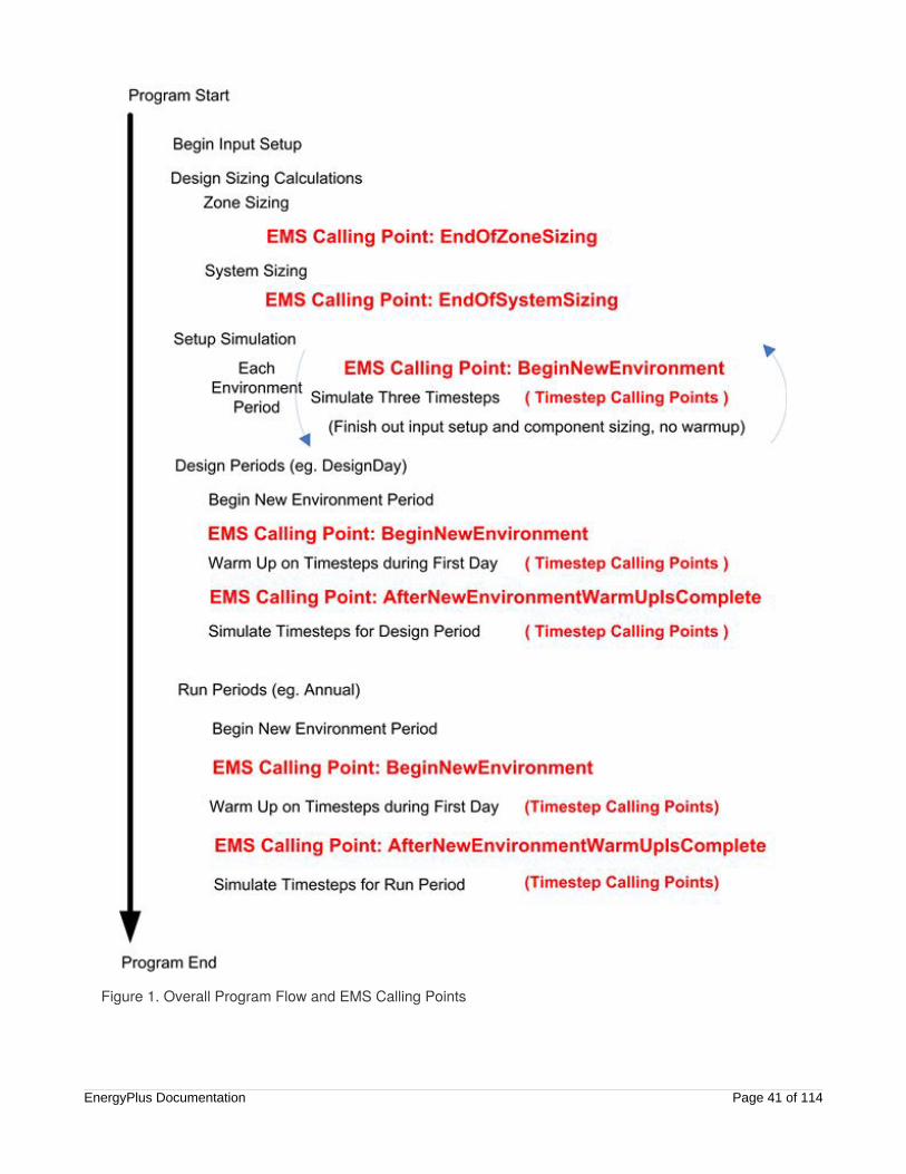
Figure 1. Overall Program Flow and EMS Calling Points
EnergyPlus Documentation Page 41 of 114
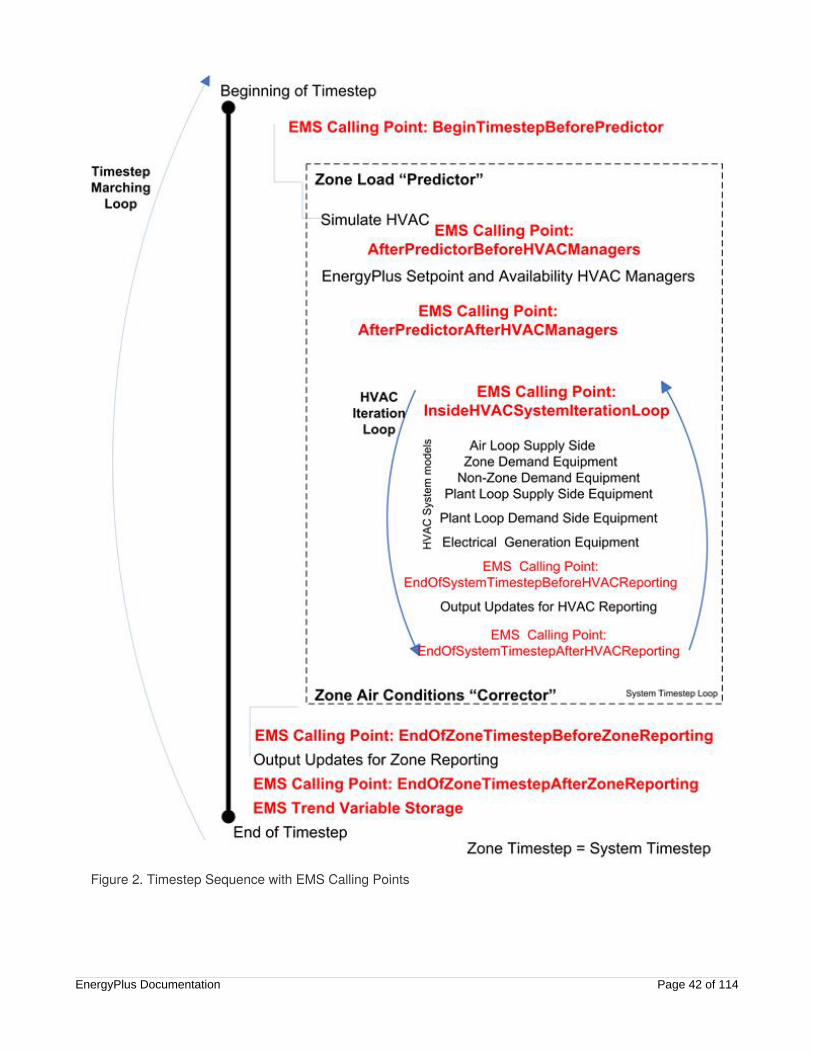
Figure 2. Timestep Sequence with EMS Calling Points
EnergyPlus Documentation Page 42 of 114

Figure 3. System Timestep Sequence with EMS Calling Points
When EnergyPlus runs a model, it first does various sizing and setup activities and then models theenvironment periods you ask for; e.g., design days and run periods. The built-in variable calledCurrentEnvironment indentifies which of these is being simulated and any given time. Figure 1 diagrams theoverall program flow starting at the top and listing certain key steps in outline form. EnergyPlus models
EnergyPlus Documentation Page 43 of 114
contain a lot of input, and the internal processes to acquire and process that input take some time tocomplete. Before the model starts doing final calculations, it may have to do various sizing calculations andautomatically design the size of components. It will also go through special setup periods that model atruncated set of timesteps for each environment period. In the diagram, this initial phase is not finished untiljust before the design periods begin. Two EMS calling points that occur only once in a given run,EndOfZoneSizing and EndOfSystemSizing, can be triggered during this initial setup phase. During thephase called “Setup Simulation,” the various timestep-based calling points diagrammed in Figure 2 will alsobe called.
Another thing that happens during the setup phase described above is that individual HVAC componentmodels access their input data and do various setup calculations in preparation for the rest of thesimulation. An EMS calling point (added for Version 7) called “AfterComponentInputReadIn” is availablefor selected HVAC components that allows triggering Erl programs at a point just after the component’sinput data have been read in but before the component’s sizing routines have executed. This calling pointis intended to be used with various actuators that are setup to override the autosize values that result fromsizing.
To model environment periods, EnergyPlus runs through a serious of timesteps. Figure 2 diagrams theprogram flow for a single timestep where the timestep for the system modeling is equal to that for the zoneload modeling. The system timestep can be shorter than the zone timestep. The usual process of modelinga timestep is to first calculate the zone loads during the “Predictor,” then model the response of the HVACsystems, and then calculate the resulting zone conditions during the “Corrector.” Within the HVAC systemmodeling, some system iterations are used to iteratively solve a system of systems. Figure 3 is a slightlymodified version Figure 2 that diagrams the situation when the timestep of the system calculations hasbeen reduced to half the length of the zone timestep.
Begin New EnvironmentThe calling point referred to with the keyword “BeginNewEnvironment” occurs once near the beginning ofeach environment period. Environment periods include sizing periods, design days, and run periods. Thiscalling point will not be useful for control actions, but is useful for initializing variables and calculations thatdo not need to be repeated during each timestep. Once a value is set, Erl variables remember the valueduring the course of a simulation. Considerable repetition can be avoided by designing Erl programs to usethis calling point for initializations and calculations that are needed only once. It is not called duringindividual timesteps.
After New Environment Warmup IsCompleteThe calling point referred to with the keyword “AfterNewEnvironmentWarmUpIsComplete” occurs once nearat the beginning of each environment period but after any warmup days are complete. This is similar to theprevious calling point. Warmup days are used to condition the transient aspects of the model beforeproceeding with the first day. This will not be useful for control actions, but would be useful for reinitializingErl programs with fresh values after the warmup days have finished running and the model is about to startthe final timestep calculations for a particular environment period.
EnergyPlus Documentation Page 44 of 114
Begin Timestep Before PredictorThe calling point called “BeginTimestepBeforePredictor” occurs near the beginning of each timestep butbefore the predictor executes. “Predictor” refers to the step in EnergyPlus modeling when the zone loadsare calculated. This calling point is useful for controlling components that affect the thermal loads the HVACsystems will then attempt to meet. Programs called from this point might actuate the building envelope orinternal gains based on current weather or on the results from the previous timestep. Demandmanagement routines might use this calling point to reduce lighting or process loads, change thermostatsettings, operate window shades, etc.
After Predictor Before HVAC ManagersThe calling point called “AfterPredictorBeforeHVACManagers” occurs after predictor and before thetraditional HVAC managers are called. It occurs at each timestep just after the predictor executes butbefore SetpointManager and AvailabilityManager models are called. It is useful for a variety of controlactions. However, if there are conflicts, the EMS control actions could be overwritten by otherSetpointManager or AvailabilityManager actions.
After Predictor After HVAC ManagersThe calling point called “AfterPredictorAfterHVACManagers” occurs after the predictor and after thetraditional HVAC managers have been called. It occurs at each timestep after the predictor executes andafter the SetpointManager and AvailabilityManager models are called. It is useful for a variety of controlactions. However, if there are conflicts, SetpointManager or AvailabilityManager actions may be overwrittenby EMS control actions.
Inside HVAC System Iteration LoopThe calling point called “InsideHVACSystemIterationLoop” occurs before HVAC systems are modeled.Within a timestep, EnergyPlus loops over the HVAC model to solve a system of systems. It recurs aftereach HVAC system iteration within each timestep and can be used for a variety of control actions thataffect system operation. Being within the iteration loop can increase the accuracy of control modeling whenthe inputs to the controls are also changing interactively. The disadvantage is extra computational expense.
End of Zone Timestep Before ReportingThe calling point called “EndOfZoneTimestepBeforeZoneReporting” occurs near the end of a zone timestepbut before output variable reporting is finalized. It is useful for custom output variables that use theZoneTimestep reporting frequency.
End of Zone Timestep After ReportingThe calling point called “EndOfZoneTimestepAfterZoneReporting” occurs at the end of a zone timestepafter output variable reporting is finalized. It is useful for preparing calculations that will go into effect thenext timestep. Its capabilities are similar to BeginTimestepBeforePredictor, except that input data for current
EnergyPlus Documentation Page 45 of 114

time, date, and weather data align with different timesteps.
End of System Timestep Before HVACReportingThe calling point called “EndOfSystemTimestepBeforeHVACReporting” occurs near the end of a systemtimestep but before output variable reporting is finalized. It is useful for custom output variables that use theSystemTimestep reporting frequency.
End of System Timestep After HVACReportingThe calling point called “EndOfSystemTimestepAfterHVACReporting” occurs at the end of a systemtimestep after output variable reporting is finalized.
End of Zone SizingThe calling point called “EndOfZoneSizing” is used to alter the results of zone sizing calculations. Itexecutes only once per simulation during the early stages and only if the model includes zone sizingcalculations. It is not useful for control applications.
End of System SizingThe calling point called “EndOfSystemSizing” is used to alter the results of air system sizing calculations. Itexecutes only once per simulation and is not useful for control applications.
After Component Model Input has BeenRead InThe calling point called “AfterComponentInputReadIn” is used to alter the results of individual autosizefields. It executes whenever one of the selected components has finished reading in its input data. Those,and only those, component models that have some type of actuator with an “Autosized” control type willalso have this calling point. This same calling point identifier is used for different HVAC components soprograms executed from this point will be repeated. Currently this calling point exists in three differentplaces: (1) after DX coil input, (2) after fan input, and (3) after unitary system input.
User Defined Component ModelThe calling point called “UserDefinedComponentModel” is used with Erl programs that are associated withuser defined component models. This calling point is executed whenever a user-defined component modelis called to simulate. The user defined component models track which program calling managers areassociated with the specific component and only those calling managers are executed when this callingpoint is triggered. This calling point is only used with calling managers referenced by the following input
EnergyPlus Documentation Page 46 of 114
objects: PlantComponent:UserDefined, Coil:UserDefined, ZoneHVAC:ForcedAir:UserDefined, orAirTerminal:SingleDuct:UserDefined.
User-Defined Component ModelsThis section provides an overview of how you can use EMS to create your own custom models for HVACand plant equipment. EMS can be used not only for controls and overriding the behavior of existingmodels, but also to implement entirely new component models of your own formulation. Such user-definedcomponent models are implemented by writing Erl programs, setting up internal variables, sensors,actuators and output variables that work in conjunction with a set of special input objects in the group called“User Defined HVAC and Plant Component Models.”
This system provides a means of modeling new types of equipment that do not yet have modelsimplemented in EnergyPlus. The capability to add new custom models should have a wide variety ofcreative applications such as evaluating the annual energy performance implications of new types ofequipment and providing a mechanism for including “exceptional calculation methods” in your EnergyPlusmodels.
This section first introduces common characteristics of the user-defined component models and then goesinto more detail on each of available component modeling shells that are used to connect user-definedmodels and algorithms to the rest of EnergyPlus’ HVAC and plant simulations.
Common CharacteristicsIn general, each of the user-defined components will:
Setup new EMS internal variables for the state conditions entering the component at each inlet nodebeing used. Internal variables serve a similar role as Sensors in terms of obtaining input data. Thedifference is that they are updated just before the component model programs execute and thereforedo not suffer the timestep lag issues that can be associated with sensors tied to output variables. Whereas most EMS internal variables are constants, those intended for use with user-definedcomponents are filled each time the component is simulated and vary over time with the mostcurrent data available.
Setup new EMS actuators for the state conditions at each outlet node being used. These actuatorsare not optional and must be used. For each air or plant connection with an active outlet node, theassociated actuators must be used and filled with valid values in order for the component model tobe properly coupled to the rest of EnergyPlus. Some of the components will also set the results attheir inlet node, for example to request a mass flow rate.
Trigger one or more specific program calling manager(s) to execute EMS programs that are called toinitialize, register, and size the component model.
Trigger one or more specific program calling manager(s) to execute EMS programs that are called toactually model the component when it is called to be simulated.
The various user-defined components have some similar input fields. Once the user gains familiarity withone of the components, many of the concepts will carry over to the other user-defined components. Theseparate objects are primarily for the purpose of distinguishing how user-defined components need to varyin order to fit with the rest of EnergyPlus.
EnergyPlus Documentation Page 47 of 114
Zone Forced Air UnitThe input object called ZoneHVAC:ForcedAir:UserDefined provides a shell for creating custom models of adevice that serves as a single-zone HVAC unit that operates by circulating air in and out of the zone. Thisdevice is analogous to those component models in the Group -- Zone Forced Air Units, such asZoneHVAC:PackagedTerminalAirConditioner or ZoneHVAC:WaterToAirHeatPump.
In addition to the primary air connection that connects to the zone, there are options for additionalconnections to a second air stream (e.g. for outdoor ventilation or heat source or sink), up to three separateplant loop connections (e.g. hot water, chilled water, heat rejection), a water supply tank, a water collectiontank, and a separate zone for skin losses.
The zone unit is associated with a thermal zone (by the ZoneHVAC:EquipmentConnections andZoneHVAC:EquipmentList objects). In EnergyPlus, when there are controlled thermal zones withthermostat (and humidistat) controls, the central routines predict the loads that zone equipment need tomeet in order to maintain control of the zone conditions. When there are multiple types of equipmentserving a zone, they are sequenced to meet heating or cooling loads in a particular order. Rather than thetotal predicted load, the second or third devices need to know the load that remains after the earlier-sequenced devices have already operated on the zone. The following internal variables are useful inputsfor controlling zone equipment in your models:
An internal variable called “Remaining Sensible Load to Heating Setpoint” provides the current valuefor the sensible load, in [W], that remains for this device that if delivered will allow the zone to reachthe heating setpoint under current conditions.
An internal variable called “Remaining Sensible Load to Cooling Setpoint” provides the current valuefor the sensible load, in [W], that remains for this device that if delivered will allow the zone to reachthe cooling setpoint under current conditions.
An internal variable called “Remaining Latent Load to Humidifying Setpoint” provides the currentvalue for the latent load, in [kg/s], that remains for this device that if delivered will allow the zone toreach the humidification setpoint under current conditions.
An internal variable called “Remaining Latent Load to Dehumidifying Setpoint” provides the currentvalue for the latent load, in [kg/s], that remains for this device that if delivered will allow the zone toreach the dehumidification setpoint under current conditions.
Primary Air ConnectionThe primary air connection includes both an inlet and an outlet that are required to be used when using thiscomponent. This is called the primary air connection because it is how the zone unit is connected to thezone. The inlet to the custom zone unit is a node that is also an exhaust outlet from the zone. Thefollowing EMS internal variables are made available for this inlet node and should be useful inputs to yourown custom models:
An internal variable called “Inlet Temperature for Primary Air Connection,” provides the current valuefor the drybulb air temperature at the component’s inlet node, in [C].
An internal variable called “Inlet Humidity Ratio for Primary Air Connection,” provides the currentvalue for the moist air humidity ratio at the component’s inlet node, in [kgWater/kgDryAir]
An internal variable called “Inlet Density for Primary Air Connection,” provides the current value for3EnergyPlus Documentation Page 48 of 114

the density of moist air at the component’s main inlet node, in [kg/m ].
An internal variable called “Inlet Specific Heat for Primary Air Connection,” provides the current valuefor the specific heat of moist air at the component’s main inlet node, in [J/kg-C].
The inlet node also has an actuator associated with it so that the rate of air flow leaving the thermal zoneand entering the unit can be passed to the rest of EnergyPlus.
An actuator called “Primary Air Connection,” with the control type “Inlet Mass Flow Rate,” in [kg/s],needs to be used. This will set the flow rate of air leaving the zone through the zone exhaust airnode.
The primary outlet for the custom zone unit is a node that is also an inlet to the zone. The following EMSactuators are created for this outlet node and must be used to pass results from the custom model to therest of EnergyPlus:
An actuator called “Primary Air Connection,” with the control type “Outlet Temperature,” in [C],needs to be used. This will set the drybulb temperature of the air leaving the zone unit and enteringthe zone through the zone air inlet node.
An actuator called “Primary Air Connection,” with the control type “Outlet Humidity Ratio,” in[kgWater/kgDryAir], needs to be used. This will set the humidity ratio of the air leaving the zone unitand entering the zone through the zone air inlet node.
An actuator called “Primary Air Connection,” with the control type “Outlet Mass Flow Rate,” in [kg/s],needs to be used. This will set the flow rate of air leaving the zone unit and entering the zonethrough the zone air inlet node.
It is not required that the primary air connections inlet and outlet mass flow rates be identical. However, ifthere is an imbalance, then the model should use the secondary air connection to balance air mass flows.
Secondary Air ConnectionThe secondary air connection provides options for an added inlet node, or outlet node, or both dependingon the user’s needs. This separate air stream can be used for outdoor air ventilation or as a source or sinkfor energy. The secondary air inlet node will often be defined to be an outdoor air node (ref.OutdoorAir:Node) but that is not required. The secondary air outlet node can be used as relief exhaustwhen the unit is providing outdoor air ventilation. If the secondary air outlet is not really connected toanything else and just releases air to the outdoors, then it isn’t necessary that moist air properties be setusing actuators because they will not impact anything else in the model.
If the secondary air connection inlet node is used, then the following internal variables and actuator aremade available:
An internal variable called “Inlet Temperature for Secondary Air Connection,” provides the currentvalue for the drybulb air temperature at the secondary inlet node, in [C].
An internal variable called “Inlet Humidity Ratio for Secondary Air Connection,” provides the currentvalue for the moist air humidity ratio at the secondary inlet node, in [kgWater/kgDryAir]
An internal variable called “Inlet Density for Secondary Air Connection,” provides the current valuefor the density of moist air at the secondary inlet node, in [kg/m ].
An internal variable called “Inlet Specific Heat for Secondary Air Connection,” provides the current
3
3
EnergyPlus Documentation Page 49 of 114

value for the specific heat of moist air at the secondary inlet node, in [J/kg-C].
An actuator called “Secondary Air Connection,” with the control type “Inlet Mass Flow Rate,” in[kg/s], needs to be used. This will set the flow rate of air entering the zone unit through thesecondary air connection inlet.
If the secondary air connection outlet node is used, then the following actuators are created:
An actuator called “Secondary Air Connection,” with the control type “Outlet Temperature,” in [C],needs to be used. This will set the drybulb temperature of the air leaving the zone unit through thesecondary air outlet node.
An actuator called “Secondary Air Connection,” with the control type “Outlet Humidity Ratio,” in[kgWater/kgDryAir], needs to be used. This will set the humidity ratio of the air leaving the zone unitthrough the secondary air outlet node.
An actuator called “Secondary Air Connection,” with the control type “Outlet Mass Flow Rate,” in[kg/s], needs to be used. This will set the flow rate of air leaving the zone unit through thesecondary air outlet node.
Plant ConnectionsThe user defined zone unit can also be connected to up to three different plants to provide hydronic-basedcooling, heating, and/or heat source or rejection.
Although the zone unit actively conditions the zone, from the point of view of plant they are demandcomponents. These plant connections are always “demand” in the sense that the zone unit will place loadsonto the plant loops serving it and are not configured to be able to meet plant loads in the way that supplyequipment could (loading mode is always DemandsLoad). These plant connections are always of the typethat when flow is requested, the loop will be operated to try and meet the flow request and if not alreadyrunning, these flow requests can turn on the loop (loop flow request mode is alwaysNeedsFlowAndTurnsLoopOn).
For plant loops, both the inlet and outlet nodes need to be used for each loop connection. TheZoneHVAC:ForcedAir:UserDefined object appears directly on the Branch object used to describe the plant. The central plant routines require that each plant component be properly initialized and registered. Specialactuators are provided for these initializations and they should be filled with values by the Erl programs thatare called by the program calling manager assigned to the zone unit for model setup and sizing. Thefollowing three actuators are created for each of “N” plant loops and must be used to properly register theplant connection:
An actuator called “Plant Connection N” with the control type “Minimum Mass Flow Rate,” in [kg/s],should be used. This will set the so-called hardware limit for component’s minimum mass flow ratewhen operating. (If not used, then the limit will be set to zero which may be okay for many if notmost models.)
An actuator called “Plant Connection N” with the control type “Maximum Mass Flow Rate,” in [kg/s],needs to be used. This will set the so-called hardware limit for the component’s maximum massflow rate when operating.
An actuator called “Plant Connection N” with the control type “Design Volume Flow Rate,” in [m /s],needs to be used. This will register the size of the component for use in sizing the plant loop andsupply equipment that will need to meet the loads.
3
EnergyPlus Documentation Page 50 of 114

For each plant loop connection that is used, the following internal variables are available for inputs to thecustom component model:
An internal variable called “Inlet Temperature for Plant Connection N” provides the current value forthe temperature of the fluid entering the component, in [C].
An internal variable called “Inlet Mass Flow Rate for Plant Connection N” provides the current valuefor the mass flow rate of the fluid entering the component, in [kg/s].
An internal variable called “Inlet Density for Plant Connection N” provides the current value for thedensity of the fluid entering the component, in [kg/m ]. This density is sensitive to the fluid type (e.g.if using glycol in the plant loop) and fluid temperature at the inlet.
An internal variable called “Inlet Specific Heat for Plant Connection N” provides the current value forthe specific heat of the fluid entering the component, in [J/kg-C]. This specific heat is sensitive to thefluid type (e.g. if using glycol in the plant loop) and fluid temperature at the inlet.
For each plant loop connection that is used, the following EMS actuators are created and must be used topass results from the custom model to the rest of EnergyPlus:
An actuator called “Plant Connection N” with the control type “Outlet Temperature,” in [C], needs tobe used. This is the temperature of the fluid leaving the zone unit through that particular plantconnection.
An actuator called “Plant Connection N” with the control type “Mass Flow Rate,” in kg/s, needs to beused. This actuator registers the component model’s request for plant fluid flow. The actual massflow rate through the component may be different than requested if the overall loop situation is suchthat not enough flow is available to meet all the various requests. In general, this actuator is used tolodge a request for flow, but the more accurate flow rate will be the internal variable called “InletMass Flow Rate for Plant Connection N.”
Water UseThe user defined zone unit can be connected to the water use models in EnergyPlus that allow modelingon-site storage. If a supply inlet water storage tank is used, then an actuator called “Water System” withthe control type “Supplied Volume Flow Rate,” in m /s, needs to be used. This sets up the zone unit as ademand component for that storage tank. If a collection outlet water storage tank is used, then an actuatorcalled “Water System” with the control type “Collected Volume Flow Rate,” in m /s, needs to be used.
Ambient ZoneThe user defined zone unit can be connected to an ambient zone and provide internal gains to that zone. The zone can be different than the one that unit is connected to via the primary air connection if desired. This is for “skin losses” that the unit might have that result from inefficiencies and other non-ideal behavior. When an ambient zone is specified, the following actuators are created that can be used for different typesof internal gains to the named zone:
An actuator called “Component Zone Internal Gain” with the control type “Sensible Heat Gain Rate,”in [W], is available. This can be used for purely convective sensible heat gains (or losses) to a zone.
An actuator called “Component Zone Internal Gain” with the control type “Return Air Heat GainRate,” in [W], is available. This can be used for purely convective sensible heat gains (or losses) to
3
3
3
EnergyPlus Documentation Page 51 of 114

the return air duct for a zone.
An actuator called “Component Zone Internal Gain” with the control type “Thermal Radiation HeatGain Rate,” in [W], is available. This can be used for thermal radiation gains (or losses) to a zone.
An actuator called “Component Zone Internal Gain” with the control type “Latent Heat Gain Rate,’ in[W], is available. This can be used for latent moisture gains (or losses) to a zone.
An actuator called “Component Zone Internal Gain” with the control type “Return Air Latent HeatGain Rate,” in [W], is available. This can be used for latent moisture gains (or losses) to a the returnair duct for a zone.
An actuator called “Component Zone Internal Gain” with the control type “Carbon Dioxide GainRate,” in [m /s], is available. This can be used for carbon dioxide gains (or losses) to a zone.
An actuator called “Component Zone Internal Gain” with the control type “Gaseous ContaminantGain Rate,” in [m /s], is available. This can be used for generic gaseous air pollutant gains (orlosses) to a zone.
Air Terminal UnitThe input object called AirTerminal:SingleDuct:UserDefined provides a shell for creating custom models foran air terminal that connects a multi-zone air handler to a thermal zone. This device is analogous to thesingle-duct terminal units in the Group – Air Distribution Equipment, such asAirTerminal:SingleDuct:VAV:Reheat or AirTerminal:SingleDuct:ConstantVolume:FourPipeInduction.
In addition to the primary air connection that connects from the air loop to the zone, there are options foradditional connections to a second air stream (e.g. for outdoor ventilation or heat source or sink), up to twoseparate plant loop connections (e.g. hot water and chilled water), a water supply tank, a water collectiontank, and a separate zone for skin losses.
The air terminal unit is a associated with a thermal zone (by the ZoneHVAC:EquipmentConnections,ZoneHVAC:EquipmentList, and ZoneHVAC:AirDistributionUnit objects). In EnergyPlus, when there arecontrolled thermal zones with thermostat (and humidistat) controls, the central routines predict the loadsthat zone equipment need to meet in order to maintain control of the zone conditions. When there aremultiple types of equipment serving a zone, they are sequenced to meet heating or cooling loads in aparticular order. Rather than the total predicted load, the second or third devices need to know the loadthat remains after the earlier-sequenced devices have already operated on the zone. The following internalvariables are useful inputs for controlling zone equipment in your models:
An internal variable called “Remaining Sensible Load to Heating Setpoint” provides the current valuefor the sensible load, in [W], that remains for this device that if delivered will allow the zone to reachthe heating setpoint under current conditions.
An internal variable called “Remaining Sensible Load to Cooling Setpoint” provides the current valuefor the sensible load, in [W], that remains for this device that if delivered will allow the zone to reachthe cooling setpoint under current conditions.
An internal variable called “Remaining Latent Load to Humidifying Setpoint” provides the currentvalue for the latent load, in [kg/s], that remains for this device that if delivered will allow the zone toreach the humidification setpoint under current conditions.
An internal variable called “Remaining Latent Load to Dehumidifying Setpoint” provides the current
3
3
EnergyPlus Documentation Page 52 of 114

value for the latent load, in [kg/s], that remains for this device that if delivered will allow the zone toreach the dehumidification setpoint under current conditions.
Primary Air ConnectionThe primary air connection includes both an inlet and an outlet that are required to be used when using thiscomponent. This called the primary air connection because it is how the terminal unit is connected fromthe air handle to the zone. The inlet to the custom air terminal unit is a node that is also the outlet from anAirLoopHVAC:ZoneSplitter object. The following EMS internal variables are made available for this inletnode and should be useful inputs to your own custom models:
An internal variable called “Inlet Temperature for Primary Air Connection,” provides the current valuefor the drybulb air temperature at the component’s inlet node, in [C].
An internal variable called “Inlet Humidity Ratio for Primary Air Connection,” provides the currentvalue for the moist air humidity ratio at the component’s inlet node, in [kgWater/kgDryAir]
An internal variable called “Inlet Density for Primary Air Connection,” provides the current value forthe density of moist air at the component’s main inlet node, in [kg/m ].
An internal variable called “Inlet Specific Heat for Primary Air Connection,” provides the current valuefor the specific heat of moist air at the component’s main inlet node, in [J/kg-C].
The inlet node also has an actuator associated with it so that the rate of air flow leaving the thermal zoneand entering the unit can be passed to the rest of EnergyPlus.
An actuator called “Primary Air Connection,” with the control type “Inlet Mass Flow Rate,” in [kg/s],needs to be used. This will set the flow rate of air leaving the zone splitter and entering the airterminal unit.
The primary outlet for the custom air terminal unit is a node that is also an inlet to the zone. The followingEMS actuators are created for this outlet node and must be used to pass results from the custom model tothe rest of EnergyPlus:
An actuator called “Primary Air Connection,” with the control type “Outlet Temperature,” in [C],needs to be used. This will set the drybulb temperature of the air leaving the air terminal unit andentering the zone through the zone air inlet node.
An actuator called “Primary Air Connection,” with the control type “Outlet Humidity Ratio,” in[kgWater/kgDryAir], needs to be used. This will set the humidity ratio of the air leaving the airterminal unit and entering the zone through the zone air inlet node.
An actuator called “Primary Air Connection,” with the control type “Outlet Mass Flow Rate,” in [kg/s],needs to be used. This will set the flow rate of air leaving the air terminal unit and entering the zonethrough the zone air inlet node.
It is not required that the primary air connections inlet and outlet mass flow rates be identical. However, ifthere is an imbalance, then the model should use the secondary air connection to balance air mass flows.
Secondary Air ConnectionThe secondary air connection provides options for an added inlet node, or outlet node, or both dependingon the user’s needs. This separate air stream can be used for outdoor air ventilation or as a source or sink
3
EnergyPlus Documentation Page 53 of 114
for energy. The secondary air inlet node will often be defined to be an outdoor air node (ref.OutdoorAir:Node) but that is not required. The secondary air outlet node can be used as relief exhaustwhen the unit is providing outdoor air ventilation. If the secondary air outlet is not really connected toanything else and just releases air to the outdoors, then it isn’t necessary that moist air properties be setusing actuators because they will not impact anything else in the model.
If the secondary air connection inlet node is used, then the following internal variables and actuator aremade available:
An internal variable called “Inlet Temperature for Secondary Air Connection,” provides the currentvalue for the drybulb air temperature at the secondary inlet node, in [C].
An internal variable called “Inlet Humidity Ratio for Secondary Air Connection,” provides the currentvalue for the moist air humidity ratio at the secondary inlet node, in [kgWater/kgDryAir]
An internal variable called “Inlet Density for Secondary Air Connection,” provides the current valuefor the density of moist air at the secondary inlet node, in [kg/m ].
An internal variable called “Inlet Specific Heat for Secondary Air Connection,” provides the currentvalue for the specific heat of moist air at the secondary inlet node, in [J/kg-C].
An actuator called “Secondary Air Connection,” with the control type “Inlet Mass Flow Rate,” in[kg/s], needs to be used. This will set the flow rate of air entering the air terminal unit through thesecondary air connection inlet.
If the secondary air connection outlet node is used, then the following actuators are created:
An actuator called “Secondary Air Connection,” with the control type “Outlet Temperature,” in [C],needs to be used. This will set the drybulb temperature of the air leaving the air terminal unitthrough the secondary air outlet node.
An actuator called “Secondary Air Connection,” with the control type “Outlet Humidity Ratio,” in[kgWater/kgDryAir], needs to be used. This will set the humidity ratio of the air leaving the airterminal unit through the secondary air outlet node.
An actuator called “Secondary Air Connection,” with the control type “Outlet Mass Flow Rate,” in[kg/s], needs to be used. This will set the flow rate of air leaving the air terminal unit through thesecondary air outlet node.
Plant ConnectionsThe user defined air terminal unit can also be connected to up to two different plants to provide hydronic-based cooling, heating, or heat source or rejection.
Although the air terminal unit actively conditions the zone, from the point of view of plant they are demandcomponents. These plant connections are always “demand” in the sense that the air terminal unit will placeloads onto the plant loops serving it and are not configured to be able to meet plant loads in the way thatsupply equipment could (loading mode is always DemandsLoad). These plant connections are always ofthe type that when flow is requested, the loop will be operated to try and meet the flow request and if notalready running, these flow requests can turn on the loop (loop flow request mode is alwaysNeedsFlowAndTurnsLoopOn).
For plant loops, both the inlet and outlet nodes need to be used for each loop connection. TheAirTerminal:SingleDuct:UserDefined object appears directly on the Branch object used to describe the
3
EnergyPlus Documentation Page 54 of 114

plant. The central plant routines require that each plant component be properly initialized and registered.Special actuators are provided for these initializations and they should be filled with values by the Erlprograms that are called by the program calling manager assigned to the air terminal unit for model setupand sizing. The following three actuators are created for each of “N” plant loops and must be used toproperly register the plant connection:
An actuator called “Plant Connection N” with the control type “Minimum Mass Flow Rate,” in [kg/s],should be used. This will set the so-called hardware limit for component’s minimum mass flow ratewhen operating. (If not used, then the limit will be set to zero which may be okay for many if notmost models.)
An actuator called “Plant Connection N” with the control type “Maximum Mass Flow Rate,” in [kg/s],needs to be used. This will set the so-called hardware limit for the component’s maximum massflow rate when operating.
An actuator called “Plant Connection N” with the control type “Design Volume Flow Rate,” in [m /s],needs to be used. This will register the size of the component for use in sizing the plant loop andsupply equipment that will need to meet the loads.
For each plant loop connection that is used, the following internal variables are available for inputs to thecustom component model:
An internal variable called “Inlet Temperature for Plant Connection N” provides the current value forthe temperature of the fluid entering the component, in [C].
An internal variable called “Inlet Mass Flow Rate for Plant Connection N” provides the current valuefor the mass flow rate of the fluid entering the component, in [kg/s].
An internal variable called “Inlet Density for Plant Connection N” provides the current value for thedensity of the fluid entering the component, in [kg/m ]. This density is sensitive to the fluid type (e.g.if using glycol in the plant loop) and fluid temperature at the inlet.
An internal variable called “Inlet Specific Heat for Plant Connection N” provides the current value forthe specific heat of the fluid entering the component, in [J/kg-C]. This specific heat is sensitive to thefluid type (e.g. if using glycol in the plant loop) and fluid temperature at the inlet.
For each plant loop connection that is used, the following EMS actuators are created and must be used topass results from the custom model to the rest of EnergyPlus:
An actuator called “Plant Connection N” with the control type “Outlet Temperature,” in [C], needs tobe used. This is the temperature of the fluid leaving the air terminal unit through that particular plantconnection.
An actuator called “Plant Connection N” with the control type “Mass Flow Rate,” in kg/s, needs to beused. This actuator registers the component model’s request for plant fluid flow. The actual massflow rate through the component may be different than requested if the overall loop situation is suchthat not enough flow is available to meet all the various requests. In general, this actuator is used tolodge a request for flow, but the more accurate flow rate will be the internal variable called “InletMass Flow Rate for Plant Connection N.”
Water UseThe user defined air terminal unit can be connected to the water use models in EnergyPlus that allow
3
3
EnergyPlus Documentation Page 55 of 114

modeling on-site storage. If a supply inlet water storage tank is used, then an actuator called “WaterSystem” with the control type “Supplied Volume Flow Rate,” in m /s, needs to be used. This sets up the airterminal unit as a demand component for that storage tank. If a collection outlet water storage tank is used,then an actuator called “Water System” with the control type “Collected Volume Flow Rate,” in m /s, needsto be used.
Ambient ZoneThe user defined air terminal unit can be connected to an ambient zone and provide internal gains to thatzone. The zone can be different than the one that unit is connected to via the primary air connection ifdesired. This is for “skin losses” that the unit might have that result from inefficiencies and other non-idealbehavior. When an ambient zone is specified, the following actuators are created that can be used fordifferent types of internal gains to the named zone:
An actuator called “Component Zone Internal Gain” with the control type “Sensible Heat Gain Rate,”in [W], is available. This can be used for purely convective sensible heat gains (or losses) to a zone.
An actuator called “Component Zone Internal Gain” with the control type “Return Air Heat GainRate,” in [W], is available. This can be used for purely convective sensible heat gains (or losses) tothe return air duct for a zone.
An actuator called “Component Zone Internal Gain” with the control type “Thermal Radiation HeatGain Rate,” in [W], is available. This can be used for thermal radiation gains (or losses) to a zone.
An actuator called “Component Zone Internal Gain” with the control type “Latent Heat Gain Rate,’ in[W], is available. This can be used for latent moisture gains (or losses) to a zone.
An actuator called “Component Zone Internal Gain” with the control type “Return Air Latent HeatGain Rate,” in [W], is available. This can be used for latent moisture gains (or losses) to a the returnair duct for a zone.
An actuator called “Component Zone Internal Gain” with the control type “Carbon Dioxide GainRate,” in [m /s], is available. This can be used for carbon dioxide gains (or losses) to a zone.
An actuator called “Component Zone Internal Gain” with the control type “Gaseous ContaminantGain Rate,” in [m /s], is available. This can be used for generic gaseous air pollutant gains (orlosses) to a zone.
Air CoilThe input object called Coil:UserDefined provides a shell for creating custom models for a coil thatprocesses air as part of an air handler. This device is analogous to coils models such asCoil:Cooling:Water, Coil:Heating:Water, and Coil:Cooling:DX:SingleSpeed, but can also be used for heat-exchanger-like devices such as HeatExchanger:AirToAir:SensibleAndLatent orEvaporativeCooler:Indirect:WetCoil.
The user defined coil model can use one or two air connections, one optional plant connection, a watersupply tank, a water collection tank, and a separate zone for skin losses.
Air Connections
3
3
3
3
EnergyPlus Documentation Page 56 of 114
Each of the two air connections that are available include both an inlet and an outlet node that are requiredfor each air connection that is used. The Coil:UserDefined object appears directly on a Branch object usedto define the supply side of an air handler, or in the AirLoopHVAC:OutdoorAirSystem:EquipmentList objectused to define outdoor air systems. The following EMS internal variables are made available for each inletnode and should be useful inputs to your own custom models:
An internal variable called “Inlet Temperature for Air Connection N,” provides the current value forthe drybulb air temperature at the component’s inlet node, in [C].
An internal variable called “Inlet Humidity Ratio for Air Connection N,” provides the current value forthe moist air humidity ratio at the component’s inlet node, in [kgWater/kgDryAir]
An internal variable called “Inlet Density for Air Connection N,” provides the current value for thedensity of moist air at the component’s main inlet node, in [kg/m ].
An internal variable called “Inlet Specific Heat for Air Connection N,” provides the current value forthe specific heat of moist air at the component’s main inlet node, in [J/kg-C].
The following EMS actuators are created for each outlet node and must be used to pass results from thecustom model to the rest of EnergyPlus:
An actuator called “Air Connection N,” with the control type “Outlet Temperature,” in [C], needs to beused. This will set the drybulb temperature of the air leaving the coil.
An actuator called “Air Connection N,” with the control type “Outlet Humidity Ratio,” in[kgWater/kgDryAir], needs to be used. This will set the humidity ratio of the air leaving the coil.
An actuator called “Air Connection N,” with the control type “Outlet Mass Flow Rate,” in [kg/s], needsto be used. This will set the flow rate of air leaving the coil.
Plant ConnectionsThe user defined coil can also be connected to one plant loop to provide hydronic-based cooling, heating, orheat source or rejection.
Although the coil actively conditions the air stream passing through it, from the point of view of plant it is ademand component. This plant connection is always “demand” in the sense that the coil will place loadsonto the plant loop serving it and is not configured to be able to meet plant loads in the way that supplyequipment could (loading mode is always DemandsLoad). This plant connection is always of the type thatwhen flow is requested, the loop will be operated to try and meet the flow request and if not alreadyrunning, these flow requests can turn on the loop (loop flow request mode is alwaysNeedsFlowAndTurnsLoopOn).
Both the inlet and outlet nodes need to be used is a loop is connected. The Coil:UserDefined objectappears directly on the Branch object used to describe the plant. The central plant routines require thateach plant component be properly initialized and registered. Special actuators are provided for theseinitializations and they should be filled with values by the Erl programs that are called by the program callingmanager assigned to the coil for model setup and sizing. The following three actuators are created for theplant loop and must be used to properly register the plant connection:
An actuator called “Plant Connection” with the control type “Minimum Mass Flow Rate,” in [kg/s],should be used. This will set the so-called hardware limit for component’s minimum mass flow ratewhen operating. (If not used, then the limit will be set to zero which may be okay for many if not
3
EnergyPlus Documentation Page 57 of 114

most models.)
An actuator called “Plant Connection” with the control type “Maximum Mass Flow Rate,” in [kg/s],needs to be used. This will set the so-called hardware limit for the component’s maximum massflow rate when operating.
An actuator called “Plant Connection” with the control type “Design Volume Flow Rate,” in [m /s],needs to be used. This will register the size of the component for use in sizing the plant loop andsupply equipment that will need to meet the loads.
When the plant loop connection is used, the following internal variables are available for inputs to thecustom component model:
An internal variable called “Inlet Temperature for Plant Connection” provides the current value forthe temperature of the fluid entering the component, in [C].
An internal variable called “Inlet Mass Flow Rate for Plant Connection” provides the current value forthe mass flow rate of the fluid entering the component, in [kg/s].
An internal variable called “Inlet Density for Plant Connection” provides the current value for thedensity of the fluid entering the component, in [kg/m ]. This density is sensitive to the fluid type (e.g.if using glycol in the plant loop) and fluid temperature at the inlet.
An internal variable called “Inlet Specific Heat for Plant Connection” provides the current value forthe specific heat of the fluid entering the component, in [J/kg-C]. This specific heat is sensitive to thefluid type (e.g. if using glycol in the plant loop) and fluid temperature at the inlet.
When the plant loop connection is used, the following EMS actuators are created and must be used to passresults from the custom model to the rest of EnergyPlus:
An actuator called “Plant Connection” with the control type “Outlet Temperature,” in [C], needs to beused. This is the temperature of the fluid leaving the coil.
An actuator called “Plant Connection” with the control type “Mass Flow Rate,” in kg/s, needs to beused. This actuator registers the component model’s request for plant fluid flow. The actual massflow rate through the component may be different than requested if the overall loop situation is suchthat not enough flow is available to meet all the various requests. In general, this actuator is used tolodge a request for flow, but the more accurate flow rate will be the internal variable called “InletMass Flow Rate for Plant Connection.”
Water UseThe user defined coil can be connected to the water use models in EnergyPlus that allow modeling on-sitestorage. If a supply inlet water storage tank is used, then an actuator called “Water System” with thecontrol type “Supplied Volume Flow Rate,” in m /s, needs to be used. This sets up the coil as a demandcomponent for that storage tank. If a collection outlet water storage tank is used, then an actuator called“Water System” with the control type “Collected Volume Flow Rate,” in m /s, needs to be used.
Ambient ZoneThe user defined coil can be connected to an ambient zone and provide internal gains to that zone. This isfor “skin losses” that the coil might have that result from inefficiencies and other non-ideal behavior. Whenan ambient zone is specified, the following actuators are created that can be used for different types of
3
3
3
3
EnergyPlus Documentation Page 58 of 114

internal gains to the named zone:
An actuator called “Component Zone Internal Gain” with the control type “Sensible Heat Gain Rate,”in [W], is available. This can be used for purely convective sensible heat gains (or losses) to a zone.
An actuator called “Component Zone Internal Gain” with the control type “Return Air Heat GainRate,” in [W], is available. This can be used for purely convective sensible heat gains (or losses) tothe return air duct for a zone.
An actuator called “Component Zone Internal Gain” with the control type “Thermal Radiation HeatGain Rate,” in [W], is available. This can be used for thermal radiation gains (or losses) to a zone.
An actuator called “Component Zone Internal Gain” with the control type “Latent Heat Gain Rate,’ in[W], is available. This can be used for latent moisture gains (or losses) to a zone.
An actuator called “Component Zone Internal Gain” with the control type “Return Air Latent HeatGain Rate,” in [W], is available. This can be used for latent moisture gains (or losses) to a the returnair duct for a zone.
An actuator called “Component Zone Internal Gain” with the control type “Carbon Dioxide GainRate,” in [m /s], is available. This can be used for carbon dioxide gains (or losses) to a zone.
An actuator called “Component Zone Internal Gain” with the control type “Gaseous ContaminantGain Rate,” in [m /s], is available. This can be used for generic gaseous air pollutant gains (orlosses) to a zone.
Plant ComponentThe input object called PlantComponent:UserDefined provides a shell for creating custom models of adevice that is part of the plant models used for hydronic-type systems. This object can be used for primaryheating or cooling devices, such as boilers or chillers.
Although the other user-defined component models can also connect to plant, they are always simple“demand” components (from the point of view of plant modeling) and their calls to simulate are led by theair side portions of the program’s calling tree. The plant-centric component here however, is called tosimulate along with other plant components (in flow order) by plant’s central routines.
The user defined plant component can use up to four different plant loop connections, one optional airconnection, a water supply tank, a water collection tank, and an ambient zone for skin losses.
Plant ConnectionsThe user defined plant component can be connected to up to four different plant loops.
For plant loops, both the inlet and outlet nodes need to be used for each loop connection. ThePlantComponent:UserDefined object appears directly on the Branch object used to describe the plant. Thecentral plant routines require that each plant component be properly initialized and registered. Specialactuators are provided for these initializations and they should be filled with values by the Erl programs thatare called by the program calling manager assigned to that particular loop connection for model setup andsizing. The following six actuators are created for each of “N” plant loops and must be used to properlyregister the plant connection:
An actuator called “Plant Connection N” with the control type “Minimum Mass Flow Rate,” in [kg/s],
3
3
EnergyPlus Documentation Page 59 of 114

should be used. This will set the so-called hardware limit for component’s minimum mass flow ratewhen operating. (If not used, then the limit will be set to zero which may be okay for many if notmost models.)
An actuator called “Plant Connection N” with the control type “Maximum Mass Flow Rate,” in [kg/s],needs to be used. This will set the so-called hardware limit for the component’s maximum massflow rate when operating.
An actuator called “Plant Connection N” with the control type “Design Volume Flow Rate,” in [m /s],needs to be used. This will register the size of the component for use in sizing the plant loop andsupply equipment that will need to meet the loads.
An actuator called “Plant Connection N” with the control type “Minimum Loading Capacity,” in [W],needs to be used if the device is to be used as a supply component with load-based operationschemes.
An actuator called “Plant connection N” with the control type “Maximum Loading Capacity,” in [W],needs to be used if the device is to be used as a supply component with load-based operationschemes.
An actuator called “Plant Connection N” with the control type “Optimal Loading Capacity,” in [W],needs to be used if the device is to be used as a supply component with load-based operationschemes.
For each plant loop connection that is used, the following internal variables are available for inputs to thecustom component model:
An internal variable called “Inlet Temperature for Plant Connection N” provides the current value forthe temperature of the fluid entering the component, in [C].
An internal variable called “Inlet Mass Flow Rate for Plant Connection N” provides the current valuefor the mass flow rate of the fluid entering the component, in [kg/s].
An internal variable called “Inlet Density for Plant Connection N” provides the current value for thedensity of the fluid entering the component, in [kg/m ]. This density is sensitive to the fluid type (e.g.if using glycol in the plant loop) and fluid temperature at the inlet.
An internal variable called “Inlet Specific Heat for Plant Connection N” provides the current value forthe specific heat of the fluid entering the component, in [J/kg-C]. This specific heat is sensitive to thefluid type (e.g. if using glycol in the plant loop) and fluid temperature at the inlet.
An internal variable called “Load Request for Plant Connection N” provides the current value for thedesired operating capacity, in [W]. This is the input for how the model is being asked to meet theloads on the supply side. This is the result of the central routines for operation schemes and shouldbe useful for controlling a plant model. (This internal variable is not made available when this plantconnection’s loading mode is set to DemandsLoad.)
For each plant loop connection that is used, the following EMS actuators are created and must be used topass results from the custom model to the rest of EnergyPlus:
An actuator called “Plant Connection N” with the control type “Outlet Temperature,” in [C], needs tobe used. This is the temperature of the fluid leaving the air terminal unit through that particular plantconnection.
An actuator called “Plant Connection N” with the control type “Mass Flow Rate,” in kg/s, needs to be
3
3
EnergyPlus Documentation Page 60 of 114

used. This actuator registers the component model’s request for plant fluid flow. The actual massflow rate through the component may be different than requested if the overall loop situation is suchthat not enough flow is available to meet all the various requests. In general, this actuator is used tolodge a request for flow, but the more accurate flow rate will be the internal variable called “InletMass Flow Rate for Plant Connection N.”
For each plant loop connection that is used, there is input required to specify the nature of the connectionwith respect to loads. One of the following choices must be selected depending on the purpose of thecomponent model.
DemandsLoad. This type of loading is used for plant connections that place a load on the loop. Connections that use this loading scheme are not set up to meet loads and interact with theoperation schemes. For example, this loading mode is appropriate for the condenser side of achiller.
MeetsLoadWithPassiveCapacity. This type of loading is used for plant connections where thecomponent has some capacity to meet loads but it is not really of the type that could be controlled. For example, a ground heat exchanger is passive because while it can provide some level of heatrejection or source, the amount will vary with current conditions and cannot usually be explicitlycontrolled.
MeetsLoadWithNominalCapacity. This type of loading is used for plant connections where thecomponent has controllable capacity to meet loads and no outlet temperature restrictions.
MeetsLoadWithNominalCapacityLowOutLimit. This type of loading is used for plant connectionswhere the component has controllable capacity to meet loads but with a lower limit on the fluidtemperature at the outlet node. For example, this can be used for a chiller evaporator connectionwhen the chiller is prevented from producing chilled water below a certain temperature limit. Whenthis type of loading is selected, an actuator is created to allow setting the low temperature limit foruse by the load dispatch routines. The actuator is called “Plant Connection N” with the control type“Low Outlet Temperature Limit,” in [C], and needs to be used.
MeetsLoadWithNominalCapacityHiOutLimit. This type of loading is used for plant connectionswhere the component has controllable capacity to meet loads but with an upper limit on the fluidtemperature at the outlet node. For example, this can be used for a boiler connection when theboiler is prevented from producing hot water above a certain temperature limit. When this type ofloading is selected, an actuator is created to allow setting the high temperature limit for use by theload dispatch routines. The actuator is called “Plant Connection N” with the control type “HighOutlet Temperature Limit,” in [C], and needs to be used.
For each plant loop connection, there is input required for the nature of the flow requests made by thecomponent with respect to determining the overall flow for the loop. Mass flow request are also importantfor resolving the flow rates in parallel branches, but the mode here is related to the problem of determiningthe overall flow rate for the loop, not the flow down one particular branch. The overall loop flow rate is afunction of all the flow requests made by the different devices on the loop and different types of deviceshave different implications for the overall loop rate. One of the following three choices must be madedepending on the nature of the plant component.
NeedsFlowIfLoopOn. Devices with this flow request mode will contribute to the overall loop flowrate but will not initiate flow themselves. Other devices on the plant loop (of typeNeedsFlowAndTurnsLoopOn ) need to make flow requests to get the loop flowing at all, but once it isflowing, this device can affect the overall loop flow rate. For example, a chiller may have a lower
EnergyPlus Documentation Page 61 of 114

limit on the allowable chilled water flow rate through its evaporator and if that lower limit is higherthan the current request for chilled water by the cooling coils, then the overall loop flow will be thatneeded by the chiller rather than the coils.
NeedsFlowAndTurnsLoopOn. Devices with this flow request mode will contribute to the overall loopflow rate and initiate flow themselves. This mode is used for demand component such as coils. Devices with this mode will initiate loops to turn on and start moving fluid.
ReceivesWhateverFlowAvailable. Devices with this flow request mode will not contribute to theoverall loop flow rate and do not initiate flow themselves. These are essentially passive devices thattake whatever flow is sent to them, such as a ground heat exchanger.
Separate program calling managers are available for each plant loop connection. The user defined plantcomponent is called to simulate by the central plant routines (whereas the other user defined componentsare called by the central HVAC routines). The calls to simulate are made for each connection and you maywant or need to perform different model calculations depending on which plant loop connection is beingsimulated at the time. There is an Erl program calling manager for initialization, setup, and sizing thatneeds to be used for each plant connection and is only called during the early plant loop initializationphase. There is also an Erl program calling manager for the model calculations to perform for each plantconnection.
Air ConnectionAn air connection is available that includes both an inlet and an outlet node. This can be used for airsource or heat rejections. The following EMS internal variables are made available for the inlet node, if it isused, and should be useful inputs to your own custom models:
An internal variable called “Inlet Temperature for Air Connection,” provides the current value for thedrybulb air temperature at the component’s inlet node, in [C].
An internal variable called “Inlet Mass Flow Rate for Air Connection,” provides the current value forthe mass flow rate of air at the component’s inlet node, in [kg/s].
An internal variable called “Inlet Humidity Ratio for Air Connection,” provides the current value forthe moist air humidity ratio at the component’s inlet node, in [kgWater/kgDryAir]
An internal variable called “Inlet Density for Air Connection,” provides the current value for thedensity of moist air at the component’s main inlet node, in [kg/m ].
An internal variable called “Inlet Specific Heat for Air Connection,” provides the current value for thespecific heat of moist air at the component’s main inlet node, in [J/kg-C].
The following EMS actuators are created for the outlet air node, if it is used, and must be used to passresults from the custom model to the rest of EnergyPlus:
An actuator called “Air Connection,” with the control type “Outlet Temperature,” in [C], needs to beused. This will set the drybulb temperature of the air leaving the component.
An actuator called “Air Connection,” with the control type “Outlet Humidity Ratio,” in[kgWater/kgDryAir], needs to be used. This will set the humidity ratio of the air leaving thecomponent.
An actuator called “Air Connection,” with the control type “Outlet Mass Flow Rate,” in [kg/s], needsto be used. This will set the flow rate of air leaving the component.
3
EnergyPlus Documentation Page 62 of 114

Water UseThe user defined plant component can be connected to the water use models in EnergyPlus that allowmodeling on-site storage. If a supply inlet water storage tank is used, then an actuator called “WaterSystem” with the control type “Supplied Volume Flow Rate,” in m /s, needs to be used. This sets up theplant component as a demand component for that storage tank. If a collection outlet water storage tank isused, then an actuator called “Water System” with the control type “Collected Volume Flow Rate,” in m /s,needs to be used.
Ambient ZoneThe user defined plant component can be connected to an ambient zone and provide internal gains to thatzone. This is for “skin losses” that the component might have that result from inefficiencies and other non-ideal behavior. When an ambient zone is specified, the following actuators are created that can be used fordifferent types of internal gains to the named zone:
An actuator called “Component Zone Internal Gain” with the control type “Sensible Heat Gain Rate,”in [W], is available. This can be used for purely convective sensible heat gains (or losses) to a zone.
An actuator called “Component Zone Internal Gain” with the control type “Return Air Heat GainRate,” in [W], is available. This can be used for purely convective sensible heat gains (or losses) tothe return air duct for a zone.
An actuator called “Component Zone Internal Gain” with the control type “Thermal Radiation HeatGain Rate,” in [W], is available. This can be used for thermal radiation gains (or losses) to a zone.
An actuator called “Component Zone Internal Gain” with the control type “Latent Heat Gain Rate,’ in[W], is available. This can be used for latent moisture gains (or losses) to a zone.
An actuator called “Component Zone Internal Gain” with the control type “Return Air Latent HeatGain Rate,” in [W], is available. This can be used for latent moisture gains (or losses) to a the returnair duct for a zone.
An actuator called “Component Zone Internal Gain” with the control type “Carbon Dioxide GainRate,” in [m /s], is available. This can be used for carbon dioxide gains (or losses) to a zone.
An actuator called “Component Zone Internal Gain” with the control type “Gaseous ContaminantGain Rate,” in [m /s], is available. This can be used for generic gaseous air pollutant gains (orlosses) to a zone.
EMS ExamplesThis section provides examples that demonstrate how to use the EMS. Each example provides a problemstatement, discusses how to approach a solution using EMS, and provides example EMS input objects. Foreach example a complete input data file is provided with the EnergyPlus release (you can find this in theExampleFiles\ directory).
A range of example applications is presented here. Each is presented in isolation for simplicity, but a muchmore comprehensive approach to EMS programs is also possible.
3
3
3
3
EnergyPlus Documentation Page 63 of 114

Example 1. Whole-Building Average ZoneAir TemperatureProblem StatementAlthough EnergyPlus can report an enormous number of output variables, you may want a custom reportvariable such as one for the average temperature in the building. Only zone-by-zone indoor airtemperatures are available. Because it is nearly always important to check that models are properlycontrolling zone air conditions, you may need to examine air temperature results from your models.Compared to scanning across the many zones in a large building, you could save time when checking amodel if you have a single value for a whole-building average temperature. Of course, you could calculatesuch a value after a run by postprocessing, but redoing this for every run is cumbersome and timeconsuming. Therefore, it would be more convenient to automatically calculate such a value inside theprogram and output it in the usual manner. For example, if we take the Small Office Reference Building(RefBldgSmallOfficeNew2004_Chicago.idf), is there a way to create a custom report variable that providesa weighted average for the indoor temperature of all the occupied zones in a model?
EMS Design DiscussionThis is a fairly simple example in that the EMS controls nothing. There are no actuators.
The example file has six zones, but one is an attic that we do not care about. Therefore, the main inputs, orEMS sensors, will be the zone air temperatures for the five occupied zones. We will useEnergyManagementSystem:Sensor objects to obtain the values for the air temperatures by mapping to theoutput variable called “Zone Mean Air Temperature.”
A model for average temperature can be constructed by using the zone air volumes as weights so largerzones have more influence than smaller zones on the resulting average. The model equation we willimplement in EMS for our new report variable is
The example file specifies the zone volume in its zone objects so we have the data needed for theweighting factors from elsewhere in the IDF. However, a study could vary the geometry such that thevolumes differ from one simulation to another. Zone Air Volume is available as internal data, so we will useEnergyManagementSystem:InternalVariable input objects to assign these weighting factors into global Erlvariables. If we did not know beforehand that Zone Air Volume was an available internal variable, we wouldhave had to prerun the model with some EMS-related objects and the appropriate level of reportingselected in an Output:EnergyManagementSystem object, and then studied the EDD output file. Note thatthe EDD file is only produced if you have EMS/Erl programs in your input file.
The custom output variable will be defined by using an EnergyManagementSystem:OutputVariable inputobject. This requires the Erl variable to be global, so we need to declare a variable. Let’s call itAverageBuildingTemp, to be global using an EnergyManagementSystem:GlobalVariable object so we havea way to connect the result calculated in the Erl program to the custom output.
There are two main considerations when selecting an EMS calling point:
=Taverage
∑ ( )TzoneVolzone
∑ ( )Volzone
(1)
EnergyPlus Documentation Page 64 of 114

The call should be toward the end of the zone timestep so the zone air temperature calculations arefinalized.
The call should be before reporting updates so our new value is available before the reporting isfinalized.
We therefore choose the EMS calling point with the key of “EndOfZoneTimestepBeforeReporting.”
EMS Input ObjectsA set of input objects to solve this problem appears below and is included in the example file called“EMSCustomOutputVariable.idf.”
EnergyManagementSystem:Sensor, T1, !Name Perimeter_ZN_1 ,! Output:Variable or Output:Meter Index Key Name Zone Mean Air Temperature ; ! Output:Variable or Output:Meter Name
EnergyManagementSystem:Sensor, T2, !Name Perimeter_ZN_2 , ! Output:Variable or Output:Meter Index Key Name Zone Mean Air Temperature ; ! Output:Variable or Output:Meter Name
EnergyManagementSystem:Sensor, T3, !Name Perimeter_ZN_3 , ! Output:Variable or Output:Meter Index Key Name Zone Mean Air Temperature ; ! Output:Variable or Output:Meter Name
EnergyManagementSystem:Sensor, T4, !Name Perimeter_ZN_4, ! Output:Variable or Output:Meter Index Key Name Zone Mean Air Temperature ;! Output:Variable or Output:Meter Name
EnergyManagementSystem:Sensor, T5, !Name Core_ZN , ! Output:Variable or Output:Meter Index Key Name Zone Mean Air Temperature ; ! Output:Variable or Output:Meter Name
EnergyManagementSystem:ProgramCallingManager, Average Building Temperature , ! Name EndOfZoneTimestepBeforeZoneReporting , ! EnergyPlus Model Calling Point AverageZoneTemps ; ! Program Name 1
EnergyManagementSystem:GlobalVariable, AverageBuildingTemp;EnergyPlus Documentation Page 65 of 114
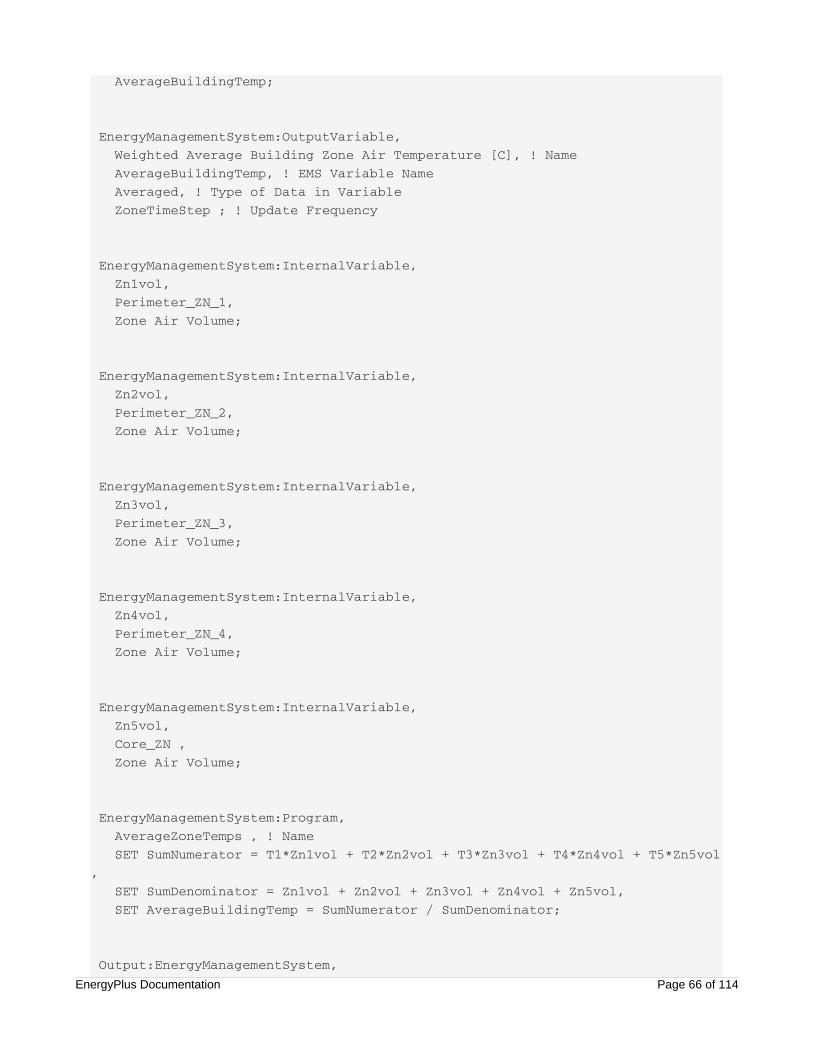
AverageBuildingTemp;
EnergyManagementSystem:OutputVariable, Weighted Average Building Zone Air Temperature [C], ! Name AverageBuildingTemp, ! EMS Variable Name Averaged, ! Type of Data in Variable ZoneTimeStep ; ! Update Frequency
EnergyManagementSystem:InternalVariable, Zn1vol, Perimeter_ZN_1, Zone Air Volume;
EnergyManagementSystem:InternalVariable, Zn2vol, Perimeter_ZN_2, Zone Air Volume;
EnergyManagementSystem:InternalVariable, Zn3vol, Perimeter_ZN_3, Zone Air Volume;
EnergyManagementSystem:InternalVariable, Zn4vol, Perimeter_ZN_4, Zone Air Volume;
EnergyManagementSystem:InternalVariable, Zn5vol, Core_ZN , Zone Air Volume;
EnergyManagementSystem:Program, AverageZoneTemps , ! Name SET SumNumerator = T1*Zn1vol + T2*Zn2vol + T3*Zn3vol + T4*Zn4vol + T5*Zn5vol, SET SumDenominator = Zn1vol + Zn2vol + Zn3vol + Zn4vol + Zn5vol, SET AverageBuildingTemp = SumNumerator / SumDenominator;
Output:EnergyManagementSystem, Verbose,EnergyPlus Documentation Page 66 of 114

Verbose, Verbose, Verbose;
Output:Variable, *, !- Key Value Weighted Average Building Zone Air Temperature, !- Variable Name timestep; !- Reporting Frequency
Example 2. Traditional Setpoint andAvailability ManagersProblem StatementThe traditional way of modeling supervisory control of HVAC systems in EnergyPlus is to useSetpointManagers and AvailabilityManagers. To gain experience with EMS, we should ask, Is there a wayto take a model such as the Large Office Reference Building (RefBldgLargeOfficeNew2004_Chicago.idf)and replicate the traditional HVAC managers by using only the EMS?
EMS Design DiscussionA review of the example file shows that three types of traditional HVAC managers are being used: scheduled setpoints, mixed air setpoints, and night cycle availability. We will discuss these separately.
The input object SetpointManager:Scheduled functions by placing a setpoint value on a specified nodebased on the value in a schedule. Therefore, our EMS program will do the same. First we will need toaccess the schedule. In this example, a schedule called Seasonal-Reset-Supply-Air-Temp-Sch contains thetemperature values desired for the air system’s supply deck. We use anEnergyManagementSystem:Sensor object based on the output variable called “Schedule Value” to fillschedule values into an Erl variable called Seasonal_Reset_SAT_Sched. Once we have the sensor andactuator setup, putting the setpoint on the node involves a single line of Erl code, “SETVAV_1_SAT_setpoint = Seasonal_Reset_SAT_Sched.”
The input object SetpointManager:Mixed air functions by placing a setpoint value on a specified nodebased on the value of the setpoint at another node and the temperature rise across the fan. Thetemperature rise is found by taking the temperature at the fan outlet node and subtracting the temperatureat the fan inlet node. The EMS needs two additional sensors to obtain these temperatures, which are set upby using a pair EnergyManagementSystem:Sensor objects. The example file has three mixed air setpointmanagers that place setpoints on the outlet of the outdoor air mixer, the outlet of the cooling coil, and theoutlet of the heating coil. Therefore, we need three actuators to place setpoints at these three nodes, whichare set up using three EnergyManagementSystem:Actuator objects. Each mixed air setpoint calculation is asimple single-line of program code such as “SET VAV_1_CoolC_Setpoint = Seasonal_Reset_SAT_Sched -(T_VAV1FanOut - T_VAV1FanIn).”
The input object AvailabilityManager:NightCycle functions by monitoring zone temperature and starting upthe air system (if needed) to keep the building within the thermostat range. The sensors here are the zoneair temperatures, which are set up by using EnergyManagementSystem:Sensor objects in the same way as
EnergyPlus Documentation Page 67 of 114

for Example 1. We will need one zone temperature sensor for each zone that is served by the air system sowe can emulate the “CycleOnAny” model being used. The other sensors we need are the desired zonetemperatures used by the thermostat. We access these temperatures directly from the schedules(HTGSETP_SCH and CLGSETP_SCH in the example) by using EnergyManagementSystem:Sensorobjects. To control the air system’s operation status, we use an EnergyManagementSystem:Actuator objectthat is assigned to an “AirLoopHVAC” component type using the control variable called “AvailabilityStatus.” EnergyPlus recognizes four availability states that control the behavior of the air system. InsideEnergyPlus these are integers, but EMS has only real-valued variables, so we will use the following wholenumbers:
NoAction = 0.0
ForceOff = 1.0
CycleOn = 2.0
CycleOnZoneFansOnly = 3.0.
The traditional AvailabilityManager:NightCycle object operates by turning on the system for a prescribedamount of time (1800 seconds in the example file), and then turning it off for the same amount of time. Youshould be able to model this starting and stopping in EMS by using Trend variables to record the history ofthe actions. However, this cycling is not necessarily how real buildings are operated, and for this examplewe do not try to precisely emulate the traditional EnergyPlus night cycle manager. Rather, we use a simplertemperature-based control to start and stop the air system for the night cycle. The algorithm first assumesan offset tolerance of 0.83°C and calculates limits for when heating should turn on and off and when coolingshould turn on and off. It then finds the maximum and minimum zone temperatures for all the zonesattached to the air system. These use the @Max and @Min built-in functions, which take on two operatorsat a time. Then a series of logic statements is used to compare temperatures and decide what theavailability status of the air system should be.
EMS Input ObjectsEMS examples are provided for the three types of traditional HVAC managers. The full set to run with notraditional managers is provided in the example file “EMSReplaceTraditionalManagers_LargeOffice.idf.”
Example input objects that replicate a scheduled setpoint manager using EMS follow.
EnergyManagementSystem:Sensor, Seasonal_Reset_SAT_Sched, !Name Seasonal-Reset-Supply-Air-Temp-Sch , ! Output:Variable Index Key Name Schedule Value; ! Output:Variable or Output:Meter Name
EnergyManagementSystem:Actuator, VAV_1_SAT_setpoint, ! Name VAV_1 Supply Equipment Outlet Node, ! Component Name System Node Setpoint, ! Component Type Temperature Setpoint; ! Control Variable
EnergyManagementSystem:Program, VAV_1_SchedSetpoint , ! Name
EnergyPlus Documentation Page 68 of 114

SET VAV_1_SAT_setpoint = Seasonal_Reset_SAT_Sched;
Example input objects that replicate a mixed air setpoint manager using EMS follow.EnergyManagementSystem:Sensor, T_VAV1FanIn, !Name VAV_1_HeatC-VAV_1_FanNode , ! Output:Variable Key Name System Node Temperature; ! Output:Variable or Output:Meter Name
EnergyManagementSystem:Sensor, T_VAV1FanOut, !Name VAV_1 Supply Equipment Outlet Node, ! Output:Variable Index Key Name System Node Temperature ; ! Output:Variable or Output:Meter Name
EnergyManagementSystem:Actuator, VAV_1_CoolC_Setpoint, ! Name VAV_1_CoolC-VAV_1_HeatCNode , ! Component Name System Node Setpoint, ! Component Type Temperature Setpoint; ! Control Variable
EnergyManagementSystem:Actuator, VAV_1_HeatC_Setpoint, ! Name VAV_1_HeatC-VAV_1_FanNode , ! Component Name System Node Setpoint, ! Component Type Temperature Setpoint; ! Control Variable
EnergyManagementSystem:Actuator, VAV_1_OA_Setpoint, ! Name VAV_1_OA-VAV_1_CoolCNode , ! Component Name System Node Setpoint, ! Component Type Temperature Setpoint; ! Control Variable
EnergyManagementSystem:Program, VAV1MixedAirManagers , ! Name SET VAV_1_CoolC_Setpoint = Seasonal_Reset_SAT_Sched - ( T_VAV1FanOut - T_VAV1FanIn), SET VAV_1_HeatC_Setpoint = Seasonal_Reset_SAT_Sched - ( T_VAV1FanOut - T_VAV1FanIn), SET VAV_1_OA_Setpoint = Seasonal_Reset_SAT_Sched - ( T_VAV1FanOut - T_VAV1FanIn);
EnergyPlus Documentation Page 69 of 114
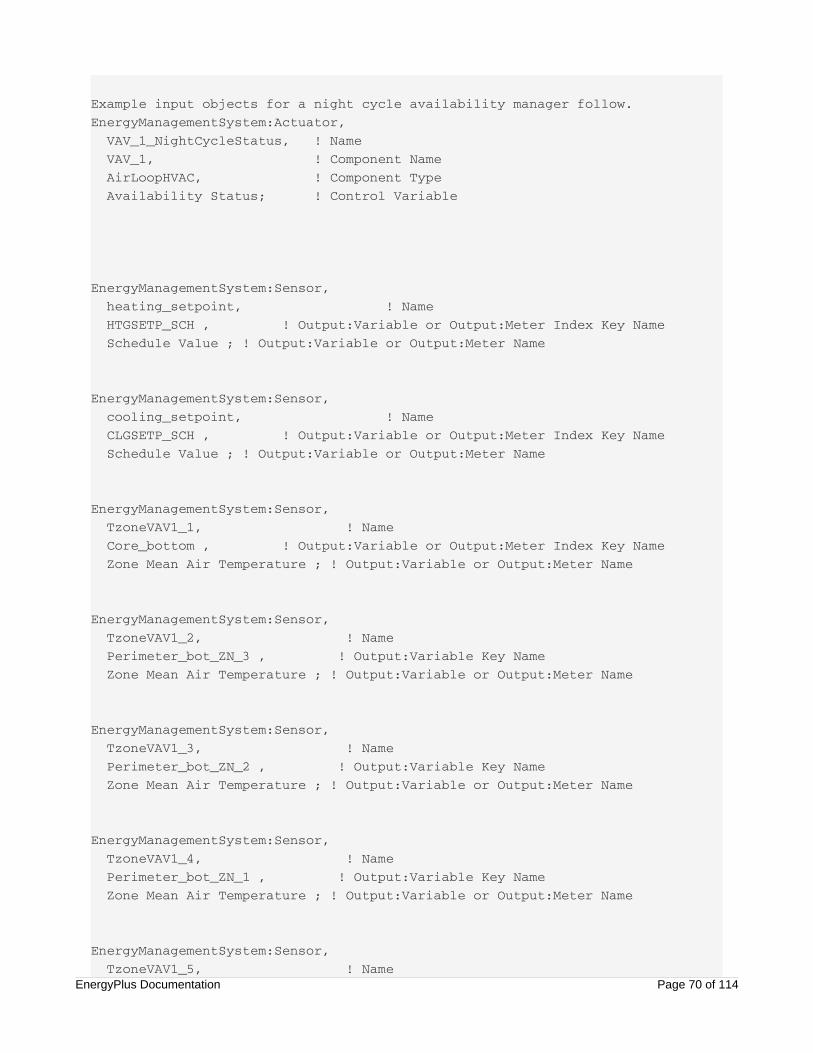
Example input objects for a night cycle availability manager follow.EnergyManagementSystem:Actuator, VAV_1_NightCycleStatus, ! Name VAV_1, ! Component Name AirLoopHVAC, ! Component Type Availability Status; ! Control Variable
EnergyManagementSystem:Sensor, heating_setpoint, ! Name HTGSETP_SCH , ! Output:Variable or Output:Meter Index Key Name Schedule Value ; ! Output:Variable or Output:Meter Name
EnergyManagementSystem:Sensor, cooling_setpoint, ! Name CLGSETP_SCH , ! Output:Variable or Output:Meter Index Key Name Schedule Value ; ! Output:Variable or Output:Meter Name
EnergyManagementSystem:Sensor, TzoneVAV1_1, ! Name Core_bottom , ! Output:Variable or Output:Meter Index Key Name Zone Mean Air Temperature ; ! Output:Variable or Output:Meter Name
EnergyManagementSystem:Sensor, TzoneVAV1_2, ! Name Perimeter_bot_ZN_3 , ! Output:Variable Key Name Zone Mean Air Temperature ; ! Output:Variable or Output:Meter Name
EnergyManagementSystem:Sensor, TzoneVAV1_3, ! Name Perimeter_bot_ZN_2 , ! Output:Variable Key Name Zone Mean Air Temperature ; ! Output:Variable or Output:Meter Name
EnergyManagementSystem:Sensor, TzoneVAV1_4, ! Name Perimeter_bot_ZN_1 , ! Output:Variable Key Name Zone Mean Air Temperature ; ! Output:Variable or Output:Meter Name
EnergyManagementSystem:Sensor, TzoneVAV1_5, ! Name
EnergyPlus Documentation Page 70 of 114

Perimeter_bot_ZN_4 , ! Output:Variable Key Name Zone Mean Air Temperature ; ! Output:Variable or Output:Meter Name
EnergyManagementSystem:Program, VAV_1_NightCycleMGR , ! Name SET Toffset = 0.8333 , ! 1.5F SET NoAction = 0.0 , SET ForceOff = 1.0 , SET CycleOn = 2.0 , SET CycleOnZoneFansOnly = 3.0 , SET VAV1_heating_TurnOn = heating_setpoint - Toffset , SET VAV1_heating_TurnOff = heating_setpoint + Toffset , SET VAV1_cooling_TurnOn = cooling_setpoint + Toffset , SET VAV1_cooling_TurnOff = cooling_setpoint - Toffset , ! find max and min for "cycleOnAny" operation SET Tmin = @MIN TzoneVAV1_1 TzoneVAV1_2 , SET Tmin = @MIN Tmin TzoneVAV1_3 , SET Tmin = @MIN Tmin TzoneVAV1_4 , SET Tmin = @MIN Tmin TzoneVAV1_5 , SET Tmax = @MAX TzoneVAV1_1 TzoneVAV1_2 , SET Tmax = @MAX Tmax TzoneVAV1_3 , SET Tmax = @MAX Tmax TzoneVAV1_4 , SET Tmax = @MAX Tmax TzoneVAV1_5 , IF Tmin < VAV1_heating_TurnOn , SET VAV_1_NightCycleStatus = CycleOn, RETURN, ! need to exit early or cooling check could also trigger ELSEIF Tmin > VAV1_heating_TurnOff, SET VAV_1_NightCycleStatus = NoAction, ENDIF, IF Tmax > VAV1_cooling_TurnOn, SET VAV_1_NightCycleStatus = CycleOn, ELSEIF Tmax < VAV1_cooling_TurnOff, SET VAV_1_NightCycleStatus = NoAction , ENDIF;
Example 3. Hygro-thermal WindowOpening Control for Airflow NetworkProblem StatementA user of EnergyPlus version 3.1 posted the following question on the Yahoo! list (circa spring 2009):
I am currently trying to model a simple ventilation system based on an
exhaust fan and outdoor air variable aperture paths that open according to
the indoor relative humidity.EnergyPlus Documentation Page 71 of 114

As I didn't find any object to directly do this, I am trying to use an
AirflowNetwork: MultiZone: Component: DetailedOpening object and its
AirflowNetwork: multizone: Surface object to model the variable aperture. But
the Ventilation Control Mode of the surface object can only be done via
Temperature or Enthalpy controls (or other not interesting for my purpose),
and not via humidity.
So my questions are:
1- is it possible to make the surface object variable according to the
relative humidity? (maybe adapting the program?)
2- or is there an other way to make it?
Because the traditional EnergyPlus controls for window openings do not support humidity-based controls(or did not as of Version 3.1), the correct response to Question #1 was “No.” But with the EMS, we cannow answer Question #2 as “Yes.” How can we take the example file called HybridVentilationControl.idfand implement humidity-based control for a detailed opening in the airflow network model?
EMS Design DiscussionThe main EMS sensor will be the zone air humidity, so we use an EnergyManagementSystem:Sensorobject that maps to the output variable called System Node Relative Humidity for the zone’s air node. Thiszone has the detailed opening.
The EMS will actuate the opening in an airflow network that is defined by the input objectAirflowNetwork:MultiZone:Component:DetailedOpening. The program will setup the actuator for thisinternally, but we need to use an EnergyManagementSystem:Actuator object to declare that we want to usethe actuator and provide the variable name we want for the Erl programs.
Because we do not know the exactly what the user had in mind, for this example we assume that thedesired behavior for the opening area is that the opening should vary linearly with room air relativehumidity. When the humidity increases, we want the opening to be larger. When the humidity decreases,we want the opening to be smaller. For relative humidity below 25% we close the opening. At 60% orhigher relative humidity, the opening should be completely open. We formulate a model equation foropening factor as
EMS Input ObjectsEMS-related input objects to solve this problem are listed below and are included in the example file called“EMSAirflowNetworkOpeningControlByHumidity.idf.”
=Fopen
0.0RH−2560−25
1.0
RH < 25%
25% ≤ RH ≤ 60%
RH > 60%
(2)
EnergyPlus Documentation Page 72 of 114
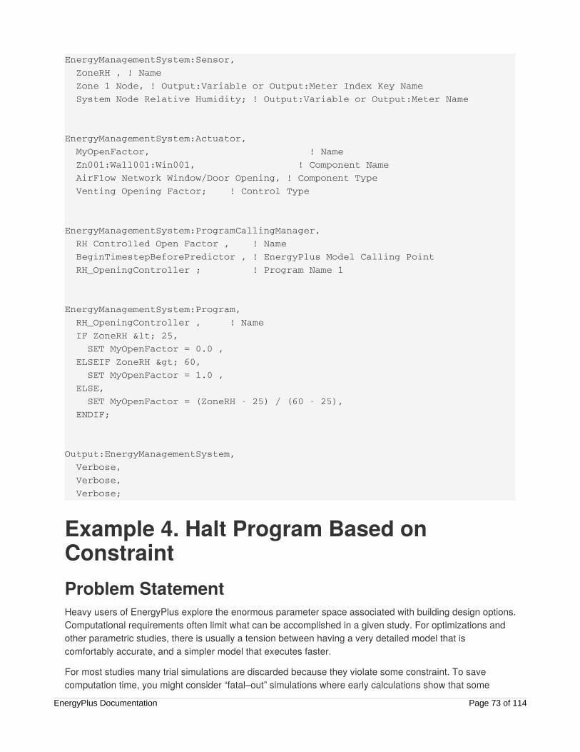
EnergyManagementSystem:Sensor, ZoneRH , ! Name Zone 1 Node, ! Output:Variable or Output:Meter Index Key Name System Node Relative Humidity; ! Output:Variable or Output:Meter Name
EnergyManagementSystem:Actuator, MyOpenFactor, ! Name Zn001:Wall001:Win001, ! Component Name AirFlow Network Window/Door Opening, ! Component Type Venting Opening Factor; ! Control Type
EnergyManagementSystem:ProgramCallingManager, RH Controlled Open Factor , ! Name BeginTimestepBeforePredictor , ! EnergyPlus Model Calling Point RH_OpeningController ; ! Program Name 1
EnergyManagementSystem:Program, RH_OpeningController , ! Name IF ZoneRH < 25, SET MyOpenFactor = 0.0 , ELSEIF ZoneRH > 60, SET MyOpenFactor = 1.0 , ELSE, SET MyOpenFactor = (ZoneRH - 25) / (60 - 25), ENDIF;
Output:EnergyManagementSystem, Verbose, Verbose, Verbose;
Example 4. Halt Program Based onConstraintProblem StatementHeavy users of EnergyPlus explore the enormous parameter space associated with building design options.Computational requirements often limit what can be accomplished in a given study. For optimizations andother parametric studies, there is usually a tension between having a very detailed model that iscomfortably accurate, and a simpler model that executes faster.
For most studies many trial simulations are discarded because they violate some constraint. To savecomputation time, you might consider “fatal–out” simulations where early calculations show that some
EnergyPlus Documentation Page 73 of 114

predetermined constraints will not be met in the final result. Many studies could save considerablecomputing resources by prematurely quitting models rather than always letting each simulation run tocompletion. All types of constraints such as poor comfort, excessive system iterations, and high energycosts could be used to kill a run. You should ask, Is there a way to use the EMS to expedite my optimalsearches by stopping models prematurely if they fail some test?
EMS Design DiscussionAs an example, let us assume that the criterion for early exit is that the model fails to be sufficientlycomfortable. We will start with the Small Hotel Reference Building example file(RefBldgSmallHotelNew2004_Chicago.idf). Short periods of discomfort are tolerated, but if the space isuncomfortable over time, we want to abandon the simulation and save computational expense. A simulationcan be stopped from within an Erl program by calling the built-in function “@FatalHaltEp.” The EMS systemhas only numeric data types, so we cannot generate text for the error message. Therefore, we choose aparticular real-numbered value to use as an error code that provides some detail on which constraintcaused early termination. In this example, we choose the value “1002.50” to indicate an average PMVexceeds 2.5 and the value “9001.30” indicates the average PMV less than 1.3. We will formulate theconstraint by using the result of the Fanger comfort model for PMV for the building’s core zone named“Core_ZN.” If the occupants will be too cold, we will call @FatalHaltEp with the error code 9001.30. If theoccupants will be too warm during a summer design day, we will fatal out with the error code 1002.50.(These values were chosen arbitrarily to demonstrate EMS; PMV of 1.3 is not necessarily a problem.)
To monitor PMV, we will use a trend variable, which we create by using theEnergyManagementSystem:TrendVariable input object. A trend variable is a log of historical values for Erlvariables. A trend log is an array that goes farther and farther back in time. For this example, we assumethe constraint is to monitor the average PMV for the previous 2-hour period. The example file has 6timesteps per hour, so each trend point is 10 minutes and a 2-hour average needs 12 timesteps. So thefield Number of Timesteps to be Logged must be 12 or larger. To access the values stored in a trendvariable, the built-in functions provided for accessing trends must be used. The @TrendAverage functioncalled with an index of 12 will return the 2-hour running average. To monitor this result of running averagePMV, we set up custom output variable using an EnergyManagementSystem:OutputVariable input object.
EMS Input ObjectsThe EMS input objects for this example follow and are contained in the example file called“EMSTestMAthAndKill.idf.”
EnergyPlus Documentation Page 74 of 114
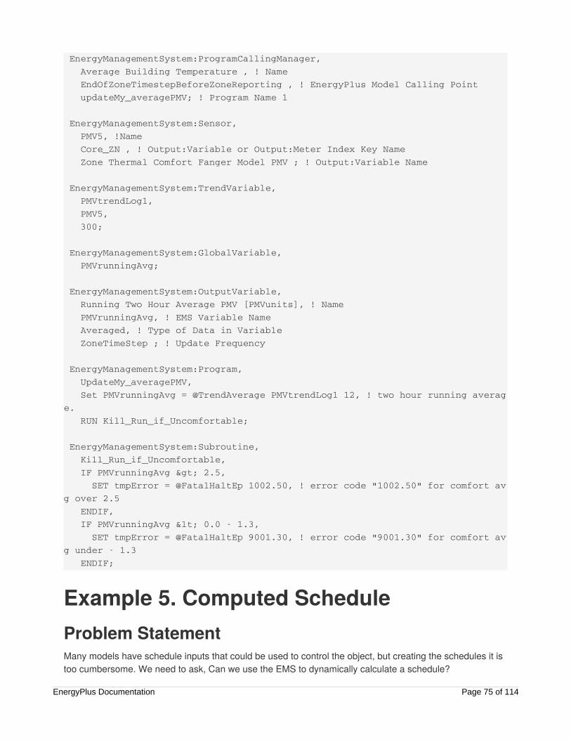
EnergyManagementSystem:ProgramCallingManager, Average Building Temperature , ! Name EndOfZoneTimestepBeforeZoneReporting , ! EnergyPlus Model Calling Point updateMy_averagePMV; ! Program Name 1
EnergyManagementSystem:Sensor, PMV5, !Name Core_ZN , ! Output:Variable or Output:Meter Index Key Name Zone Thermal Comfort Fanger Model PMV ; ! Output:Variable Name
EnergyManagementSystem:TrendVariable, PMVtrendLog1, PMV5, 300;
EnergyManagementSystem:GlobalVariable, PMVrunningAvg;
EnergyManagementSystem:OutputVariable, Running Two Hour Average PMV [PMVunits], ! Name PMVrunningAvg, ! EMS Variable Name Averaged, ! Type of Data in Variable ZoneTimeStep ; ! Update Frequency
EnergyManagementSystem:Program, UpdateMy_averagePMV, Set PMVrunningAvg = @TrendAverage PMVtrendLog1 12, ! two hour running average. RUN Kill_Run_if_Uncomfortable;
EnergyManagementSystem:Subroutine, Kill_Run_if_Uncomfortable, IF PMVrunningAvg > 2.5, SET tmpError = @FatalHaltEp 1002.50, ! error code "1002.50" for comfort avg over 2.5 ENDIF, IF PMVrunningAvg < 0.0 - 1.3, SET tmpError = @FatalHaltEp 9001.30, ! error code "9001.30" for comfort avg under - 1.3 ENDIF;
Example 5. Computed ScheduleProblem StatementMany models have schedule inputs that could be used to control the object, but creating the schedules it istoo cumbersome. We need to ask, Can we use the EMS to dynamically calculate a schedule?
EnergyPlus Documentation Page 75 of 114

EMS Design DiscussionAs an example, we will take the model from example 1 and use the EMS to replicate the heating andcooling zone temperature setpoint schedules. The input object Schedule:Constant has been set up to beavailable as an actuator. We then add EnergyManagementSystem:Actuator objects that set these actuatorsup as Erl variables.
To devise an Erl program to compute the schedule, we need to use the built-in variables that describe timeand day. The built-in variable Hour will provide information about the time of day; DayOfWeek will provideinformation about whether it is the weekend or a weekday.
EMS Input ObjectsExample EMS input for computing a schedule for heating and cooling setpoints follows and are containedin the example file called “EMSCustomSchedule.idf.”
Schedule:Constant, CLGSETP_SCH, Temperature, 24.0;
EnergyManagementSystem:Actuator, myCLGSETP_SCH_Override, CLGSETP_SCH,Schedule:Constant,Schedule Value;
EnergyManagementSystem:ProgramCallingManager, My Setpoint Schedule Calculator Example, BeginTimestepBeforePredictor, MyComputedCoolingSetpointProg, MyComputedHeatingSetpointProg;
EnergyManagementSystem:Program, MyComputedCoolingSetpointProg, IF (DayOfWeek == 1), Set myCLGSETP_SCH_Override = 30.0 , ELSEIF (Holiday == 3.0) && (DayOfMonth == 21) && (Month == 1), !winter design day Set myCLGSETP_SCH_Override = 30.0 , ELSEIF HOUR < 6 , Set myCLGSETP_SCH_Override = 30.0 , ELSEIF (Hour >= 6) && (Hour < 22) && (DayOfWeek >=2) && (DayOfWeek <=6) , Set myCLGSETP_SCH_Override = 24.0 , ELSEIF (Hour >= 6) && (hour < 18) && (DayOfWeek == 7) Set myCLGSETP_SCH_Override = 24.0 , ELSEIF (Hour >= 6) && (hour >= 18) && (DayOfWeek == 7) Set myCLGSETP_SCH_Override = 30.0 , ELSEIF (Hour >= 22) , Set myCLGSETP_SCH_Override = 30.0 , ENDIF;
EnergyPlus Documentation Page 76 of 114

ENDIF;
Schedule:Constant, HTGSETP_SCH, Temperature, 21.0;
EnergyManagementSystem:Actuator, myHTGSETP_SCH, HTGSETP_SCH,Schedule:Constant,Schedule Value;
EnergyManagementSystem:Program, MyComputedHeatingSetpointProg, Set locHour = Hour, ! echo out for debug Set locDay = DayOfWeek, ! echo out for debug Set locHol = Holiday, ! echo out for debug IF (DayOfWeek == 1), Set myHTGSETP_SCH = 15.6 , ELSEIF (Holiday == 3.0) && (DayOfYear == 21), !winter design day Set myHTGSETP_SCH = 21.0 , ELSEIF HOUR < 5 , Set myHTGSETP_SCH = 15.6 , ELSEIF (Hour >= 5) && (Hour < 19) && (DayOfWeek >=2) && (DayOfWeek <=6) , Set myHTGSETP_SCH = 21.0 , ELSEIF (Hour >= 6) && (hour < 17) && (DayOfWeek == 7), Set myHTGSETP_SCH = 21.0 , ELSEIF (Hour >= 6) && (hour >= 17) && (DayOfWeek == 7) , Set myHTGSETP_SCH = 15.6 , ELSEIF (Hour >= 19) , Set myHTGSETP_SCH = 15.6 , ENDIF;
Example 6. Window Shade ControlProblem StatementEnergyPlus offers a wide range of control options in the WindowProperty:ShadingControl object, but it iseasy to imagine custom schemes for controlling shades or blinds that are not available. We need to ask,Can we use the EMS to override the shading controls?
EMS Design DiscussionWe will take the example file PurchAirWindowBlind.idf and use EMS to add a new control scheme. This filehas an interior blind that can be either “on” or “off.” The control scheme has three parts:
Deploy the blind whenever too much direct sun would enter the zone and cause discomfort for theoccupants.
EnergyPlus Documentation Page 77 of 114

Deploy the blind whenever there is a significant cooling load.
Leave the blind open whenever the first two constraints have not triggered.
We assume that a model for the direct sun control is based on incidence angle, where the angle is definedas zero for normal incidence relative to the plane of the window. When the direct solar incidence angle isless than 45 degrees, we want to draw the blind. EnergyPlus has a report variable called “Surface Ext SolarBeam Cosine Of Incidence Angle,” for which we will use a sensor in ourEnergyManagementSystem:Sensor input object. This sensor is a cosine value that we turn into an anglevalue with the built-in function @ArcCos. Then we will use the built-in function @RadToDeg to convert fromradians to degrees. This new window/solar incidence angle in degree may be an interesting report variable,so we use an EnergyManagementSystem:OutputVariable input object to create custom output.
Because the transmitted solar is a problem only when there is a cooling load, we also trigger the blindbased on the current data for cooling. The report variable called “Zone/Sys Sensible Cooling Rate” is usedin an EMS sensor to obtain an Erl variable with the most recent data about zone cooling load required tomeet setpoint. When this value is positive, we know the zone cannot make good use of passive solarheating, so we close the blind.
The EMS actuator will override the operation of a WindowProperty:ShadingControl input object. Related tothis, the EDD file shows
! <EnergyManagementSystem:Actuator Available>, Component Unique Name, Component Type, ControlType
EnergyManagementSystem:Actuator Available,ZN001:WALL001:WIN001,Window Shading Control,ControlStatus
Although the user-defined name for the WindowProperty:ShadingControl is “INCIDENT SOLAR ONBLIND,” the component unique name of the actuator that is available is called “ZN001:WALL001:WIN001.” There could be multiple windows, all with shades, and each is governed by a singleWindowProperty:ShadingControl input object. The EMS actuator could override each window separately.The Control Type is called “Control Status,” and requires you to set the status to one of a set of possiblecontrol flags. For this case, with only an interior shade, there are two states for the actuator to take. Thefirst shows the shade is “off,” and corresponds to a value of 0.0. The second shows the interior shade is“on,” and corresponds to a value of 6.0.
EMS Input ObjectsThe EMS input objects for this example follow and are contained in the example file called“EMSWindowShadeControl.idf.”
Output:EnergyManagementSystem, Verbose, Verbose, Verbose;
EnergyManagementSystem:Sensor, Solar_Beam_Incident_Cos, !Name Zn001:Wall001:Win001,! Output:Variable or Output:Meter Index Key Name Surface Outside Face Beam Solar Incident Angle Cosine Value; ! Var Name
EnergyPlus Documentation Page 78 of 114

Output:Variable, Zn001:Wall001:Win001, Surface Outside Face Beam Solar Incident Angle Cosine Value, Timestep;
EnergyManagementSystem:Sensor, Zone_Sensible_Cool_Rate, !Name RESISTIVE ZONE,! Output:Variable or Output:Meter Index Key Name Zone Air System Sensible Cooling Rate; ! Var Name
Output:Variable, RESISTIVE ZONE, Zone Air System Sensible Cooling Rate, Timestep;
EnergyManagementSystem:ProgramCallingManager, Window Shading Device EMS Controller, ! Name BeginTimestepBeforePredictor , ! EnergyPlus Model Calling Point Set_Shade_Control_State ; ! Program Name 1
EnergyManagementSystem:Actuator, Zn001_Wall001_Win001_Shading_Deploy_Status, ! Name Zn001:Wall001:Win001, ! Component Name Surface name with shade controls Window Shade Control, ! Component Type Control Status; ! Control Type
EnergyManagementSystem:Program, Set_Shade_Control_State, ! Name ! Set IncidentAngleRad = @ArcCos Solar_Beam_Incident_Cos, Set IncidentAngle = @RadToDeg IncidentAngleRad, ! IF IncidentAngle < 45 , ! Block intense direct sun Set Zn001_Wall001_Win001_Shading_Deploy_Status = Shade_Status_Interior_Blind_On, ELSEIF Zone_Sensible_Cool_Rate > 20, ! block to reduce cooling loads Set Zn001_Wall001_Win001_Shading_Deploy_Status = Shade_Status_Interior_Blind_On, Else, Set Zn001_Wall001_Win001_Shading_Deploy_Status = Shade_Status_Off , ENDIF ;
EnergyPlus Documentation Page 79 of 114

EnergyManagementSystem:OutputVariable, Erl Shading Control Status, ! Name Zn001_Wall001_Win001_Shading_Deploy_Status, ! EMS Variable Name Averaged, ! Type of Data in Variable ZoneTimeStep ; ! Update Frequency
EnergyManagementSystem:OutputVariable, Erl Zn001:Wall001:Win001 Incident Angle, ! Name IncidentAngle, ! EMS Variable Name Averaged, ! Type of Data in Variable ZoneTimeStep ; ! Update Frequency
EnergyManagementSystem:GlobalVariable, IncidentAngle;
Output:Variable, *, Erl Shading Control Status, Timestep;
Output:Variable, *, Erl Zn001:Wall001:Win001 Incident Angle, Timestep;
EnergyManagementSystem:ProgramCallingManager, Init Window Shading Device Control Constants, ! Name BeginNewEnvironment , ! EnergyPlus Model Calling Point InitializeShadeControlFlags ; ! Program Name 1
EnergyManagementSystem:GlobalVariable, Shade_Status_None; EnergyManagementSystem:GlobalVariable, Shade_Status_Off ; EnergyManagementSystem:GlobalVariable, Shade_Status_Interior_Shade_On; EnergyManagementSystem:GlobalVariable, Shade_Status_Switchable_Dark; EnergyManagementSystem:GlobalVariable, Shade_Status_Exterior_Shade_On; EnergyManagementSystem:GlobalVariable, Shade_Status_Interior_Blind_On; EnergyManagementSystem:GlobalVariable, Shade_Status_Exterior_Blind_On; EnergyManagementSystem:GlobalVariable, Shade_Status_Between_Glass_Shade_On; EnergyManagementSystem:GlobalVariable, Shade_Status_Between_Glass_Blind_On;
EnergyPlus Documentation Page 80 of 114
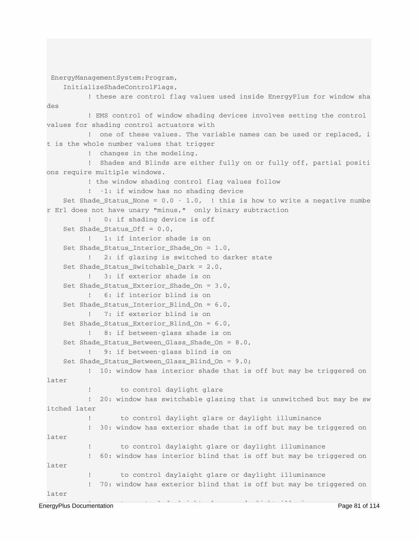
EnergyManagementSystem:Program, InitializeShadeControlFlags, ! these are control flag values used inside EnergyPlus for window shades ! EMS control of window shading devices involves setting the control values for shading control actuators with ! one of these values. The variable names can be used or replaced, it is the whole number values that trigger ! changes in the modeling. ! Shades and Blinds are either fully on or fully off, partial positions require multiple windows. ! the window shading control flag values follow ! -1: if window has no shading device Set Shade_Status_None = 0.0 - 1.0, ! this is how to write a negative number Erl does not have unary "minus," only binary subtraction ! 0: if shading device is off Set Shade_Status_Off = 0.0, ! 1: if interior shade is on Set Shade_Status_Interior_Shade_On = 1.0, ! 2: if glazing is switched to darker state Set Shade_Status_Switchable_Dark = 2.0, ! 3: if exterior shade is on Set Shade_Status_Exterior_Shade_On = 3.0, ! 6: if interior blind is on Set Shade_Status_Interior_Blind_On = 6.0, ! 7: if exterior blind is on Set Shade_Status_Exterior_Blind_On = 6.0, ! 8: if between-glass shade is on Set Shade_Status_Between_Glass_Shade_On = 8.0, ! 9: if between-glass blind is on Set Shade_Status_Between_Glass_Blind_On = 9.0; ! 10: window has interior shade that is off but may be triggered on later ! to control daylight glare ! 20: window has switchable glazing that is unswitched but may be switched later ! to control daylight glare or daylight illuminance ! 30: window has exterior shade that is off but may be triggered on later ! to control daylaight glare or daylight illuminance ! 60: window has interior blind that is off but may be triggered on later ! to control daylaight glare or daylight illuminance ! 70: window has exterior blind that is off but may be triggered on later ! to control daylaight glare or daylight illuminanceEnergyPlus Documentation Page 81 of 114
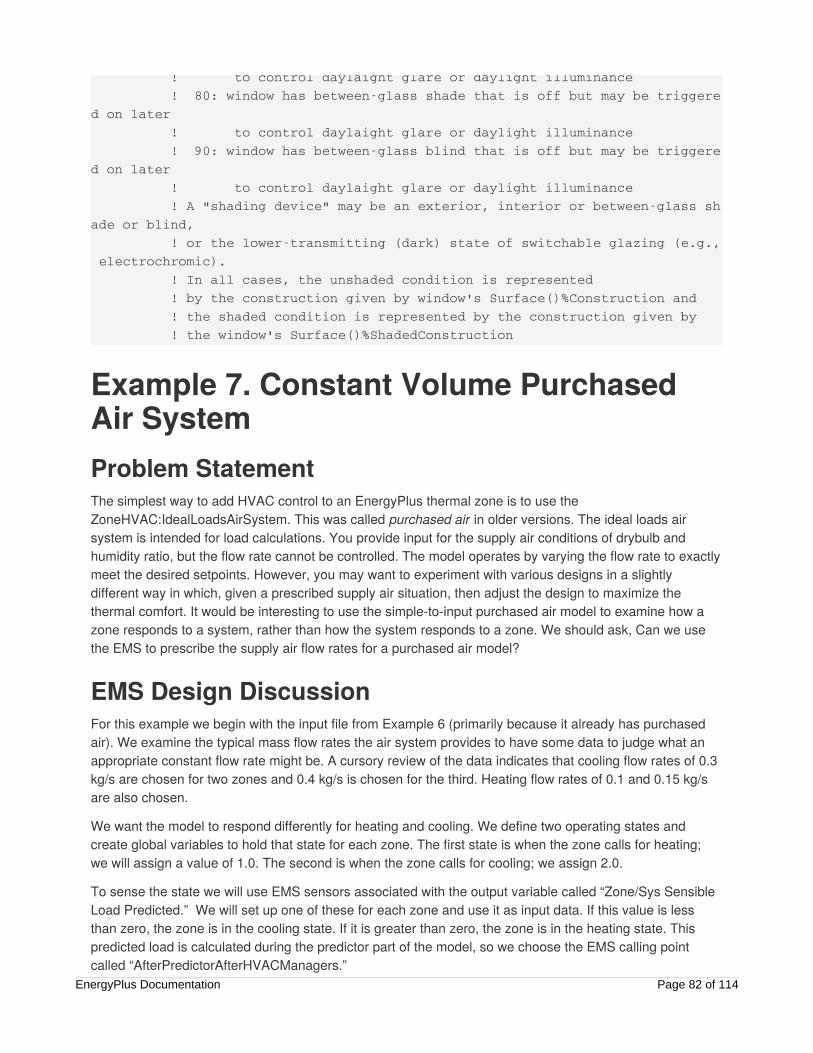
! to control daylaight glare or daylight illuminance ! 80: window has between-glass shade that is off but may be triggered on later ! to control daylaight glare or daylight illuminance ! 90: window has between-glass blind that is off but may be triggered on later ! to control daylaight glare or daylight illuminance ! A "shading device" may be an exterior, interior or between-glass shade or blind, ! or the lower-transmitting (dark) state of switchable glazing (e.g., electrochromic). ! In all cases, the unshaded condition is represented ! by the construction given by window's Surface()%Construction and ! the shaded condition is represented by the construction given by ! the window's Surface()%ShadedConstruction
Example 7. Constant Volume PurchasedAir SystemProblem StatementThe simplest way to add HVAC control to an EnergyPlus thermal zone is to use theZoneHVAC:IdealLoadsAirSystem. This was called purchased air in older versions. The ideal loads airsystem is intended for load calculations. You provide input for the supply air conditions of drybulb andhumidity ratio, but the flow rate cannot be controlled. The model operates by varying the flow rate to exactlymeet the desired setpoints. However, you may want to experiment with various designs in a slightlydifferent way in which, given a prescribed supply air situation, then adjust the design to maximize thethermal comfort. It would be interesting to use the simple-to-input purchased air model to examine how azone responds to a system, rather than how the system responds to a zone. We should ask, Can we usethe EMS to prescribe the supply air flow rates for a purchased air model?
EMS Design DiscussionFor this example we begin with the input file from Example 6 (primarily because it already has purchasedair). We examine the typical mass flow rates the air system provides to have some data to judge what anappropriate constant flow rate might be. A cursory review of the data indicates that cooling flow rates of 0.3kg/s are chosen for two zones and 0.4 kg/s is chosen for the third. Heating flow rates of 0.1 and 0.15 kg/sare also chosen.
We want the model to respond differently for heating and cooling. We define two operating states andcreate global variables to hold that state for each zone. The first state is when the zone calls for heating;we will assign a value of 1.0. The second is when the zone calls for cooling; we assign 2.0.
To sense the state we will use EMS sensors associated with the output variable called “Zone/Sys SensibleLoad Predicted.” We will set up one of these for each zone and use it as input data. If this value is lessthan zero, the zone is in the cooling state. If it is greater than zero, the zone is in the heating state. Thispredicted load is calculated during the predictor part of the model, so we choose the EMS calling pointcalled “AfterPredictorAfterHVACManagers.”
EnergyPlus Documentation Page 82 of 114

An EMS actuator is available for the ideal loads air system that overrides the air mass flow rate (kg/s)delivered by the system when it is on. The override is not absolute in that the model will still apply the limitsdefined in the input object and overrides only if the system is “on.” The internal logic will turn off the airsystem if the zone is in the thermostat dead band or scheduled “off” by availability managers. This “off”state is modeled inside the ideal loads air system so it does not need to be calculated in Erl. This controlleads to a constant volume system that cycles in an attempt to control the zone conditions. In practice, itcan achieve relatively good control when loads do not exceed the available capacity.
EMS Input ObjectsA set of EMS input objects for a constant volume purchased air system serving three zones follows arecontained in the example file called “EMSConstantVolumePurchAir.idf.”
EnergyManagementSystem:ProgramCallingManager, Constant Volume Purchased Air Example, ! Name AfterPredictorAfterHVACManagers , ! EnergyPlus Model Calling Point Determine_Purch_Air_State, ! Program Name 1 Set_Purch_Air;
EnergyManagementSystem:Program, Determine_Purch_Air_State, ! Name ! State representation: 1.0 is heating, 2.0 is cooling IF (Sensible_Load_Zone_1 <= 0.0) , SET Zone_1_State = 2.0, ELSEIF (Sensible_Load_Zone_1 > 0.0) , SET Zone_1_State = 1.0, ENDIF, IF (Sensible_Load_Zone_2 <= 0.0) , SET Zone_2_State = 2.0, ELSEIF (Sensible_Load_Zone_2 > 0.0) , SET Zone_2_State = 1.0, ENDIF, IF (Sensible_Load_Zone_3 <= 0.0) , SET Zone_3_State = 2.0, ELSEIF (Sensible_Load_Zone_3 > 0.0) , SET Zone_3_State = 1.0, ENDIF;
EnergyManagementSystem:Program, Set_Purch_Air, IF ( Zone_1_State == 2.0), SET ZONE_1_AIR_Mdot = 0.3, ELSEIF (Zone_1_State == 1.0), SET ZONE_1_AIR_Mdot = 0.1, ENDIF, IF ( Zone_2_State == 2.0),EnergyPlus Documentation Page 83 of 114
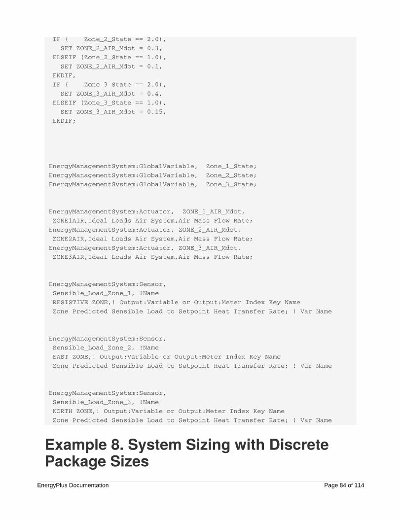
IF ( Zone_2_State == 2.0), SET ZONE_2_AIR_Mdot = 0.3, ELSEIF (Zone_2_State == 1.0), SET ZONE_2_AIR_Mdot = 0.1, ENDIF, IF ( Zone_3_State == 2.0), SET ZONE_3_AIR_Mdot = 0.4, ELSEIF (Zone_3_State == 1.0), SET ZONE_3_AIR_Mdot = 0.15, ENDIF;
EnergyManagementSystem:GlobalVariable, Zone_1_State; EnergyManagementSystem:GlobalVariable, Zone_2_State; EnergyManagementSystem:GlobalVariable, Zone_3_State;
EnergyManagementSystem:Actuator, ZONE_1_AIR_Mdot, ZONE1AIR,Ideal Loads Air System,Air Mass Flow Rate; EnergyManagementSystem:Actuator, ZONE_2_AIR_Mdot, ZONE2AIR,Ideal Loads Air System,Air Mass Flow Rate; EnergyManagementSystem:Actuator, ZONE_3_AIR_Mdot, ZONE3AIR,Ideal Loads Air System,Air Mass Flow Rate;
EnergyManagementSystem:Sensor, Sensible_Load_Zone_1, !Name RESISTIVE ZONE,! Output:Variable or Output:Meter Index Key Name Zone Predicted Sensible Load to Setpoint Heat Transfer Rate; ! Var Name
EnergyManagementSystem:Sensor, Sensible_Load_Zone_2, !Name EAST ZONE,! Output:Variable or Output:Meter Index Key Name Zone Predicted Sensible Load to Setpoint Heat Transfer Rate; ! Var Name
EnergyManagementSystem:Sensor, Sensible_Load_Zone_3, !Name NORTH ZONE,! Output:Variable or Output:Meter Index Key Name Zone Predicted Sensible Load to Setpoint Heat Transfer Rate; ! Var Name
Example 8. System Sizing with DiscretePackage Sizes
EnergyPlus Documentation Page 84 of 114
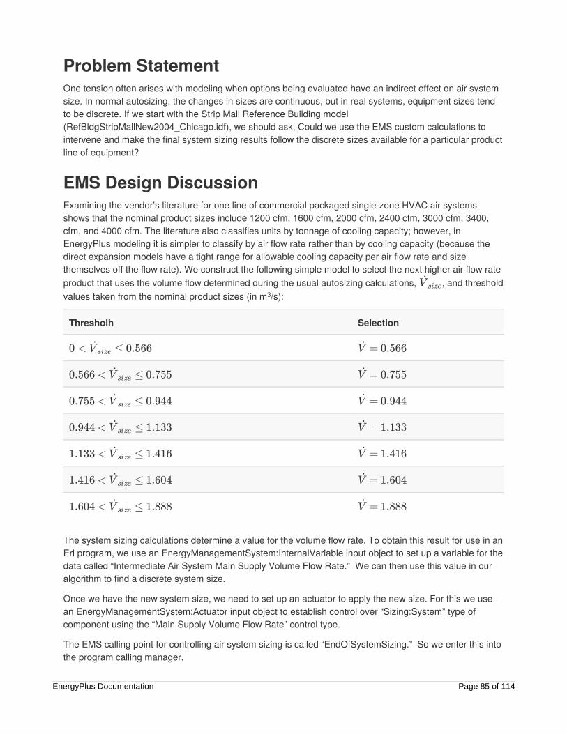
Problem StatementOne tension often arises with modeling when options being evaluated have an indirect effect on air systemsize. In normal autosizing, the changes in sizes are continuous, but in real systems, equipment sizes tendto be discrete. If we start with the Strip Mall Reference Building model(RefBldgStripMallNew2004_Chicago.idf), we should ask, Could we use the EMS custom calculations tointervene and make the final system sizing results follow the discrete sizes available for a particular productline of equipment?
EMS Design DiscussionExamining the vendor’s literature for one line of commercial packaged single-zone HVAC air systemsshows that the nominal product sizes include 1200 cfm, 1600 cfm, 2000 cfm, 2400 cfm, 3000 cfm, 3400,cfm, and 4000 cfm. The literature also classifies units by tonnage of cooling capacity; however, inEnergyPlus modeling it is simpler to classify by air flow rate rather than by cooling capacity (because thedirect expansion models have a tight range for allowable cooling capacity per air flow rate and sizethemselves off the flow rate). We construct the following simple model to select the next higher air flow rateproduct that uses the volume flow determined during the usual autosizing calculations, , and thresholdvalues taken from the nominal product sizes (in m /s):
Thresholh Selection
The system sizing calculations determine a value for the volume flow rate. To obtain this result for use in anErl program, we use an EnergyManagementSystem:InternalVariable input object to set up a variable for thedata called “Intermediate Air System Main Supply Volume Flow Rate.” We can then use this value in ouralgorithm to find a discrete system size.
Once we have the new system size, we need to set up an actuator to apply the new size. For this we usean EnergyManagementSystem:Actuator input object to establish control over “Sizing:System” type ofcomponent using the “Main Supply Volume Flow Rate” control type.
The EMS calling point for controlling air system sizing is called “EndOfSystemSizing.” So we enter this intothe program calling manager.
V̇ size3
0 < ≤ 0.566V̇ size = 0.566V̇
0.566 < ≤ 0.755V̇ size = 0.755V̇
0.755 < ≤ 0.944V̇ size = 0.944V̇
0.944 < ≤ 1.133V̇ size = 1.133V̇
1.133 < ≤ 1.416V̇ size = 1.416V̇
1.416 < ≤ 1.604V̇ size = 1.604V̇
1.604 < ≤ 1.888V̇ size = 1.888V̇
EnergyPlus Documentation Page 85 of 114

For this example, we modify the example file called “RefBldgStripMallNew2004_Chicago.idf.” This file has10 separate packaged units, so rather than repeat the algorithm several times, we use a subroutine so thesame Erl code can be reused for each air system. The subroutine has two arguments that we will declareas global variables: the input for continuous size and the output for the discrete size.
EMS Input ObjectsA set of input objects for EMS control for discrete resizing of 10 air systems follows and is included in theexample file called “EMSDiscreteAirSystemSizes.idf.”
Output:EnergyManagementSystem, Verbose, Verbose, Verbose;
EnergyManagementSystem:ProgramCallingManager, Apply Discrete Package Sizes to Air System Sizing , ! Name EndOfSystemSizing , ! EnergyPlus Model Calling Point Resize_PSZ_To_Match_Product_Availability; ! Program Name 1
EnergyManagementSystem:Program, Resize_PSZ_To_Match_Product_Availability , ! Name SET argMainVdot = PSZ_1_CalcMainSupVdot, RUN Select_Discrete_Nominal_Air_Flow, SET PSZ_1_MainSupVdotSet = argDiscreteMainVdot, SET argMainVdot = PSZ_2_CalcMainSupVdot, RUN Select_Discrete_Nominal_Air_Flow, SET PSZ_2_MainSupVdotSet = argDiscreteMainVdot, SET argMainVdot = PSZ_3_CalcMainSupVdot, RUN Select_Discrete_Nominal_Air_Flow, SET PSZ_3_MainSupVdotSet = argDiscreteMainVdot, SET argMainVdot = PSZ_4_CalcMainSupVdot, RUN Select_Discrete_Nominal_Air_Flow, SET PSZ_4_MainSupVdotSet = argDiscreteMainVdot, SET argMainVdot = PSZ_5_CalcMainSupVdot, RUN Select_Discrete_Nominal_Air_Flow, SET PSZ_5_MainSupVdotSet = argDiscreteMainVdot, SET argMainVdot = PSZ_6_CalcMainSupVdot, RUN Select_Discrete_Nominal_Air_Flow, SET PSZ_6_MainSupVdotSet = argDiscreteMainVdot, SET argMainVdot = PSZ_7_CalcMainSupVdot, RUN Select_Discrete_Nominal_Air_Flow, SET PSZ_7_MainSupVdotSet = argDiscreteMainVdot, SET argMainVdot = PSZ_8_CalcMainSupVdot, RUN Select_Discrete_Nominal_Air_Flow, SET PSZ_8_MainSupVdotSet = argDiscreteMainVdot,EnergyPlus Documentation Page 86 of 114
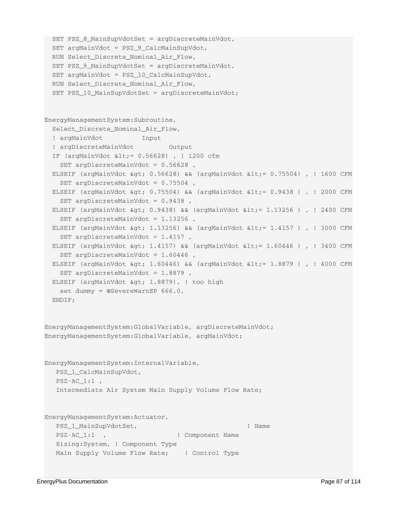
SET PSZ_8_MainSupVdotSet = argDiscreteMainVdot, SET argMainVdot = PSZ_9_CalcMainSupVdot, RUN Select_Discrete_Nominal_Air_Flow, SET PSZ_9_MainSupVdotSet = argDiscreteMainVdot, SET argMainVdot = PSZ_10_CalcMainSupVdot, RUN Select_Discrete_Nominal_Air_Flow, SET PSZ_10_MainSupVdotSet = argDiscreteMainVdot;
EnergyManagementSystem:Subroutine, Select_Discrete_Nominal_Air_Flow, ! argMainVdot Input ! argDiscreteMainVdot Output IF (argMainVdot <= 0.56628) , ! 1200 cfm SET argDiscreteMainVdot = 0.56628 , ELSEIF (argMainVdot > 0.56628) && (argMainVdot <= 0.75504) , ! 1600 CFM SET argDiscreteMainVdot = 0.75504 , ELSEIF (argMainVdot > 0.75504) && (argMainVdot <= 0.9438 ) , ! 2000 CFM SET argDiscreteMainVdot = 0.9438 , ELSEIF (argMainVdot > 0.9438) && (argMainVdot <= 1.13256 ) , ! 2400 CFM SET argDiscreteMainVdot = 1.13256 , ELSEIF (argMainVdot > 1.13256) && (argMainVdot <= 1.4157 ) , ! 3000 CFM SET argDiscreteMainVdot = 1.4157 , ELSEIF (argMainVdot > 1.4157) && (argMainVdot <= 1.60446 ) , ! 3400 CFM SET argDiscreteMainVdot = 1.60446 , ELSEIF (argMainVdot > 1.60446) && (argMainVdot <= 1.8879 ) , ! 4000 CFM SET argDiscreteMainVdot = 1.8879 , ELSEIF (argMainVdot > 1.8879), ! too high set dummy = @SevereWarnEP 666.0, ENDIF;
EnergyManagementSystem:GlobalVariable, argDiscreteMainVdot;EnergyManagementSystem:GlobalVariable, argMainVdot;
EnergyManagementSystem:InternalVariable, PSZ_1_CalcMainSupVdot, PSZ-AC_1:1 , Intermediate Air System Main Supply Volume Flow Rate;
EnergyManagementSystem:Actuator, PSZ_1_MainSupVdotSet, ! Name PSZ-AC_1:1 , ! Component Name Sizing:System, ! Component Type Main Supply Volume Flow Rate; ! Control Type
EnergyPlus Documentation Page 87 of 114
EnergyManagementSystem:InternalVariable, PSZ_2_CalcMainSupVdot, PSZ-AC_2:2 , Intermediate Air System Main Supply Volume Flow Rate;
EnergyManagementSystem:Actuator, PSZ_2_MainSupVdotSet, ! Name PSZ-AC_2:2 , ! Component Name Sizing:System, ! Component Type Main Supply Volume Flow Rate; ! Control Type
EnergyManagementSystem:InternalVariable, PSZ_3_CalcMainSupVdot, PSZ-AC_3:3 , Intermediate Air System Main Supply Volume Flow Rate;
EnergyManagementSystem:Actuator, PSZ_3_MainSupVdotSet, ! Name PSZ-AC_3:3 , ! Component Name Sizing:System, ! Component Type Main Supply Volume Flow Rate; ! Control Type
EnergyManagementSystem:InternalVariable, PSZ_4_CalcMainSupVdot, PSZ-AC_4:4 , Intermediate Air System Main Supply Volume Flow Rate;
EnergyManagementSystem:Actuator, PSZ_4_MainSupVdotSet, ! Name PSZ-AC_4:4 , ! Component Name Sizing:System, ! Component Type Main Supply Volume Flow Rate; ! Control Type
EnergyManagementSystem:InternalVariable, PSZ_5_CalcMainSupVdot, PSZ-AC_5:5 , Intermediate Air System Main Supply Volume Flow Rate;
EnergyManagementSystem:Actuator, PSZ_5_MainSupVdotSet, ! Name PSZ-AC_5:5 , ! Component NameEnergyPlus Documentation Page 88 of 114
PSZ-AC_5:5 , ! Component Name Sizing:System, ! Component Type Main Supply Volume Flow Rate; ! Control Type
EnergyManagementSystem:InternalVariable, PSZ_6_CalcMainSupVdot, PSZ-AC_6:6 , Intermediate Air System Main Supply Volume Flow Rate;
EnergyManagementSystem:Actuator, PSZ_6_MainSupVdotSet, ! Name PSZ-AC_6:6 , ! Component Name Sizing:System, ! Component Type Main Supply Volume Flow Rate; ! Control Type
EnergyManagementSystem:InternalVariable, PSZ_7_CalcMainSupVdot, PSZ-AC_7:7 , Intermediate Air System Main Supply Volume Flow Rate;
EnergyManagementSystem:Actuator, PSZ_7_MainSupVdotSet, ! Name PSZ-AC_7:7 , ! Component Name Sizing:System, ! Component Type Main Supply Volume Flow Rate; ! Control Type
EnergyManagementSystem:InternalVariable, PSZ_8_CalcMainSupVdot, PSZ-AC_8:8 , Intermediate Air System Main Supply Volume Flow Rate;
EnergyManagementSystem:Actuator, PSZ_8_MainSupVdotSet, ! Name PSZ-AC_8:8 , ! Component Name Sizing:System, ! Component Type Main Supply Volume Flow Rate; ! Control Type
EnergyManagementSystem:InternalVariable, PSZ_9_CalcMainSupVdot, PSZ-AC_9:9 , Intermediate Air System Main Supply Volume Flow Rate;
EnergyPlus Documentation Page 89 of 114

EnergyManagementSystem:Actuator, PSZ_9_MainSupVdotSet, ! Name PSZ-AC_9:9 , ! Component Name Sizing:System, ! Component Type Main Supply Volume Flow Rate; ! Control Type
EnergyManagementSystem:InternalVariable, PSZ_10_CalcMainSupVdot, PSZ-AC_10:10 , Intermediate Air System Main Supply Volume Flow Rate;
EnergyManagementSystem:Actuator, PSZ_10_MainSupVdotSet, ! Name PSZ-AC_10:10 , ! Component Name Sizing:System, ! Component Type Main Supply Volume Flow Rate; ! Control Type
Example 9. Demand ManagementProblem StatementDemand management refers to controlling a building to reduce the peak electrical power draws or otherwiseimprove the load profile from the perspective of the electric utility. Managing electricity demand is animportant application for EMS. We should ask, Can we take the model from example 2 and use the EMS toadd demand management?
EMS Design DiscussionExample 2 is a model of a large office building, but unfortunately the utility tariff is not a demand-basedrate. Therefore, we change to a different set of utility rate input objects so the model has demand charges.
For this example, we assume that demand is managed by turning down the lights and increasing thecooling setpoint. The EMS calling point chosen is “BeginTimestepBeforePredictor” because it allows you tochange the lighting power levels and temperature setpoints before you predict the zone loads.
To manage the demand, we first need to develop some targets based on some a priori idea of what level ofdemand should be considered “high.” Therefore, we first run the model without demand management andnote the simulation results for demand. There are many ways to obtain the demand results, but one methodis to obtain them from the tabular report for Tariffs called “Native Variables.” In that report, the row calledPeakDemand is the demand used to calculate demand charges and is listed in kW. We will use thesevalues to construct a target level of demand for each month by taking these results and multiplying by 0.85in an effort to reduce demand by 15%. For example, the demand for January was 1,154.01 kW, so wemake our target level to be 0.85 * 1154.01 = 980.91 kW and the demand for August was 1,555.20 kW, sothe target is 0.85 * 1555.20 = 1,321.92 kW.
To develop our Erl program, we separate the overall task into two parts:EnergyPlus Documentation Page 90 of 114
1) Determine the current state of demand management control.
2) Set the controls based on that control state.
We then divide the Erl programs into two main programs and give them descriptive names: “Determine_Current_Demand_Manage_State”; “Dispatch_Demand_Changes_By_State.”
The Erl program to determine the control state determines the current status for the demand managementcontrols. You can record and manage the control state by setting the value of a global variable called“argDmndMngrState.” For this example, we develop four control states that represent four levels ofdemand management:
Level 1 is assigned a value of 0.0 and represents no override to implement changes to demand-related controls.
Level 2 is assigned a value of 1.0 and represents moderately aggressive overrides for demand-related controls.
Level 3 is assigned a value of 2.0 and represents more aggressive override.
Level 4 is assigned a value of 3.0 and represents the most aggressive overrides.
We develop an algorithm for choosing the control state by assuming it should be a function of how close thecurrent power level is to the target power level, the current direction for changes in power use, and therecent history of control state. The current demand is obtained by using a sensor that is based on the “TotalElectric Demand” output variable. This current demand is compared to the target demand levels discussedas well as a “level 1” demand level that is set to be 90% of the target. If the current demand is higher thanthe level 1 demand but lower than the target, the state will tend to be at level 1. If the current demand ishigher than the target, the current state will be either level 2 or level 3 depending on the trend direction.However, we do not want the response to be too quick because it leads to too much bouncing betweencontrol states. Therefore, we also introduce some numerical damping with the behavior that once a controlstate is selected it should be selected for at least two timesteps before dropping down to a lower level. Thisdamping is modeled with the help of a trend variable that records the control state over time so we canretrieve what the control state was during the past two timesteps.
Once the control state is determined, the Erl programs will use EMS actuators to override controls basedon the state. The following table summarizes the control adjustments used in our example for each controlstate.
Table 9. Example 9 Demand Management Adjustments by Control State
Control State Lighting Power Ahjustment Factor Cooling Thermostat Offset
0 None none
1 0.9 + 0.8ºC
2 0.8 + 1.5ºC
3 0.7 + 2.0ºC
For control state level 0, the actuators are all set to Null so they stop overriding controls and return themodel to normal operation.
EnergyPlus Documentation Page 91 of 114

To alter the lighting power density with EMS, you could use either a direct method that employs a Lightsactuator or an indirect method that modifies the lighting schedule. For this example we use the directmethod with EnergyManagementSystem:Actuator input objects that enable you to override the ElectricPower Level for each zone’s lights. We also set up internal variables to obtain the Lighting Power DesignLevel for each Lights object. Finally, we set up an EMS sensor to obtain the lighting schedule value to usein Erl programs. If the demand management control state is 1, 2, or 3, we use the following model todetermine a new lighting power level:
Power = (Adjustment Factor) × (Lighting Power Design Level) × (Schedule Value)
There are also two ways to alter the cooling setpoint with EMS. To dynamically alter the cooling setpoints,we modify the schedule rather than directly actuating Zone Temperature Control actuators. Changing theschedule allows one actuator to override all the zones; the more direct approach would require actuatorsfor each zone. (This can be used to advantage if different zones are to be managed differently.) Thealgorithm applies an offset depending on the control state. In the input file, the schedule for coolingsetpoints is called CLGSETP_SCH, so we set up an actuator for this Schedule Value. Because thealgorithm is a simple offset from the original schedule, we need to keep track of the values in the originalschedule. We cannot use the same schedule as an input to the algorithm because once an actuatoroverrides the schedule value it will corrupt the original schedule. This would be an example of a circularreference problem. Therefore, we make a copy of the cooling setpoint schedule, naming itCLGSETP_SCH_Copy, and use the copy in a EnergyManagementSystem:Sensor object to obtain thecurrent scheduled value for the setpoint. When we override the CLGSETP_SCH schedule, it will notcorrupt the values from the CLGSTEP_SCH_Copy schedule used as input.
EMS Input ObjectsThe main input objects that implement this example of demand management are listed below and areincluded in the example file called “EMSDemandManager_LargeOffice.idf.” The results indicate thatdemand management controls could reduce electricity costs by around $40,000 or 10%.
EnergyManagementSystem:ProgramCallingManager, Demand Manager Demonstration, BeginTimestepBeforePredictor, Determine_Current_Demand_Manage_State, Dispatch_Demand_Controls_By_State;
EnergyManagementSystem:Program, Determine_Current_Demand_Manage_State, Set localDemand = CurntFacilityElectDemand / 1000.0 , Set CurrntTrend = @TrendDirection FacilityElectTrend 4, IF (Month == 1) , Set argTargetDemand = 0.85 * 1154.01, Set argCrntDmnd = localDemand, Set argTrendDirection = CurrntTrend, ELSEIF (Month == 2), Set argTargetDemand = 0.85 * 1150.85 , Set argCrntDmnd = localDemand, Set argTrendDirection = CurrntTrend, ELSEIF (Month == 3), Set argTargetDemand = 0.85 * 1313.56 ,EnergyPlus Documentation Page 92 of 114
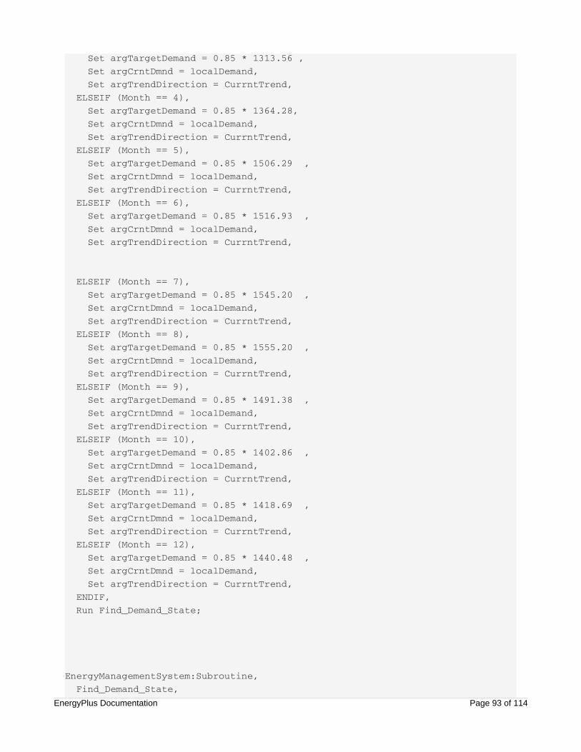
Set argTargetDemand = 0.85 * 1313.56 , Set argCrntDmnd = localDemand, Set argTrendDirection = CurrntTrend, ELSEIF (Month == 4), Set argTargetDemand = 0.85 * 1364.28, Set argCrntDmnd = localDemand, Set argTrendDirection = CurrntTrend, ELSEIF (Month == 5), Set argTargetDemand = 0.85 * 1506.29 , Set argCrntDmnd = localDemand, Set argTrendDirection = CurrntTrend, ELSEIF (Month == 6), Set argTargetDemand = 0.85 * 1516.93 , Set argCrntDmnd = localDemand, Set argTrendDirection = CurrntTrend,
ELSEIF (Month == 7), Set argTargetDemand = 0.85 * 1545.20 , Set argCrntDmnd = localDemand, Set argTrendDirection = CurrntTrend, ELSEIF (Month == 8), Set argTargetDemand = 0.85 * 1555.20 , Set argCrntDmnd = localDemand, Set argTrendDirection = CurrntTrend, ELSEIF (Month == 9), Set argTargetDemand = 0.85 * 1491.38 , Set argCrntDmnd = localDemand, Set argTrendDirection = CurrntTrend, ELSEIF (Month == 10), Set argTargetDemand = 0.85 * 1402.86 , Set argCrntDmnd = localDemand, Set argTrendDirection = CurrntTrend, ELSEIF (Month == 11), Set argTargetDemand = 0.85 * 1418.69 , Set argCrntDmnd = localDemand, Set argTrendDirection = CurrntTrend, ELSEIF (Month == 12), Set argTargetDemand = 0.85 * 1440.48 , Set argCrntDmnd = localDemand, Set argTrendDirection = CurrntTrend, ENDIF, Run Find_Demand_State;
EnergyManagementSystem:Subroutine, Find_Demand_State, ! argTargetDemand Input kW level targetEnergyPlus Documentation Page 93 of 114

! argTargetDemand Input kW level target ! argCrntDmnd Input kW level current ! argTrendDirection Input J/hour ! argDmndMngrState Output value code, 0.0 = no management, ! 1.0 = level 1 demand management ! 2.0 = level 2 demand management ! 3.0 = level 3 demand management Set DmndStateX1 = @TrendValue Demand_Mgr_State_Trend 1, Set DmndStateX2 = @TrendValue Demand_Mgr_State_Trend 2, Set Level1Demand = 0.9 * argTargetDemand, Set argCrntDmnd = argCrntDmnd, Set argTargetDemand = argTargetDemand, SET argDmndMngrState = DmndStateX1, ! initialize to last state then model changes IF (argCrntDmnd > Level1Demand) && (argCrntDmnd <argTargetDemand) && (argTrendDirection > 0.0),
IF DmndStateX1 <= 1.0, SET argDmndMngrState = 1.0, ELSEIF (DmndStateX1 == 2.0) && (DmndStateX2 < 2.0), SET argDmndMngrState = 2.0, ! go at least two timesteps at 2.0 ELSEIF (DmndStateX1 == 3.0) && (DmndStateX2 == 3.0), SET argDmndMngrState = 2.0, ELSEIF (DmndStateX1 == 3.0) && (DmndStateX2 == 2.0), SET argDmndMngrState = 3.0, ! go at least two timesteps at 3.0 ENDIF,
ELSEIF (argCrntDmnd > argTargetDemand) && (argTrendDirection < 0.0), IF DmndStateX1 <= 2.0, SET argDmndMngrState = 2.0, ELSEIF (DmndStateX1 == 3.0) && (DmndStateX2 == 2.0) , ! go at least two timesteps at 3.0 SET argDmndMngrState = 3.0, ELSEIF (DmndStateX1 == 3.0) && (DmndStateX2 == 3.0), SET argDmndMngrState = 2.0, ENDIF,
ELSEIF (argCrntDmnd > argTargetDemand) && (argTrendDirection >= 0.0), Set argDmndMngrState = 3.0, ENDIF;
EnergyManagementSystem:Program, Dispatch_Demand_Controls_By_State, IF (argDmndMngrState == 0.0),EnergyPlus Documentation Page 94 of 114

IF (argDmndMngrState == 0.0), RUN Unset_Demand_Controls, ELSEIF (argDmndMngrState == 1.0), RUN Set_Demand_Level1_Controls, ELSEIF (argDmndMngrState == 2.0), Run Set_Demand_Level2_Controls, ELSEIF (argDmndMngrState == 3.0), Run Set_Demand_Level3_Controls, ENDIF;
EnergyManagementSystem:Subroutine, Unset_Demand_Controls, SET Set_Cooling_Setpoint_Sched = Null, SET Set_Basement_Lights = Null, SET Set_Core_bottom_Lights = Null, SET Set_Core_mid_Lights = Null, SET Set_Core_top_Lights = Null, SET Set_Perimeter_bot_ZN_3_Lights = Null, SET Set_Perimeter_bot_ZN_2_Lights = Null, SET Set_Perimeter_bot_ZN_1_Lights = Null, SET Set_Perimeter_bot_ZN_4_Lights = Null, SET Set_Perimeter_mid_ZN_3_Lights = Null, SET Set_Perimeter_mid_ZN_2_Lights = Null, SET Set_Perimeter_mid_ZN_1_Lights = Null, SET Set_Perimeter_mid_ZN_4_Lights = Null, SET Set_Perimeter_top_ZN_3_Lights = Null, SET Set_Perimeter_top_ZN_2_Lights = Null, SET Set_Perimeter_top_ZN_1_Lights = Null, SET Set_Perimeter_top_ZN_4_Lights = Null;
EnergyManagementSystem:Subroutine, Set_Demand_Level1_Controls, ! set lighting power to 90% of what it would otherwise be SET Set_Cooling_Setpoint_Sched = Cooling_Setpoint_Sched + 0.8, ! add 0.8 deg C to cooling setpoint SET Set_Basement_Lights = 0.90 * Basement_Lights * BLDG_LIGHT_SCH, SET Set_Core_bottom_Lights = 0.90 * Core_bottom_Lights * BLDG_LIGHT_SCH, SET Set_Core_mid_Lights = 0.90 * Core_mid_Lights * BLDG_LIGHT_SCH, SET Set_Core_top_Lights = 0.90 * Core_top_Lights * BLDG_LIGHT_SCH, SET Set_Perimeter_bot_ZN_3_Lights = 0.90 * Perimeter_bot_ZN_3_Lights * BLDG_LIGHT_SCH, SET Set_Perimeter_bot_ZN_2_Lights = 0.90 * Perimeter_bot_ZN_2_Lights * BLDG_LIGHT_SCH, SET Set_Perimeter_bot_ZN_1_Lights = 0.90 * Perimeter_bot_ZN_1_Lights * BLDG_LIGHT_SCH,EnergyPlus Documentation Page 95 of 114

IGHT_SCH, SET Set_Perimeter_bot_ZN_4_Lights = 0.90 * Perimeter_bot_ZN_4_Lights * BLDG_LIGHT_SCH, SET Set_Perimeter_mid_ZN_3_Lights = 0.90 * Perimeter_mid_ZN_3_Lights * BLDG_LIGHT_SCH, SET Set_Perimeter_mid_ZN_2_Lights = 0.90 * Perimeter_mid_ZN_2_Lights * BLDG_LIGHT_SCH, SET Set_Perimeter_mid_ZN_1_Lights = 0.90 * Perimeter_mid_ZN_1_Lights * BLDG_LIGHT_SCH, SET Set_Perimeter_mid_ZN_4_Lights = 0.90 * Perimeter_mid_ZN_4_Lights * BLDG_LIGHT_SCH, SET Set_Perimeter_top_ZN_3_Lights = 0.90 * Perimeter_top_ZN_3_Lights * BLDG_LIGHT_SCH, SET Set_Perimeter_top_ZN_2_Lights = 0.90 * Perimeter_top_ZN_2_Lights * BLDG_LIGHT_SCH, SET Set_Perimeter_top_ZN_1_Lights = 0.90 * Perimeter_top_ZN_1_Lights * BLDG_LIGHT_SCH, SET Set_Perimeter_top_ZN_4_Lights = 0.90 * Perimeter_top_ZN_4_Lights * BLDG_LIGHT_SCH;
EnergyManagementSystem:Subroutine, Set_Demand_Level2_Controls, ! set lighting power to 80% of what it would otherwise be SET Set_Cooling_Setpoint_Sched = Cooling_Setpoint_Sched + 1.5, ! add 1.5 deg C to cooling setpoint SET Set_Basement_Lights = 0.80 * Basement_Lights * BLDG_LIGHT_SCH, SET Set_Core_bottom_Lights = 0.80 * Core_bottom_Lights * BLDG_LIGHT_SCH, SET Set_Core_mid_Lights = 0.80 * Core_mid_Lights * BLDG_LIGHT_SCH, SET Set_Core_top_Lights = 0.80 * Core_top_Lights * BLDG_LIGHT_SCH, SET Set_Perimeter_bot_ZN_3_Lights = 0.80 * Perimeter_bot_ZN_3_Lights * BLDG_LIGHT_SCH, SET Set_Perimeter_bot_ZN_2_Lights = 0.80 * Perimeter_bot_ZN_2_Lights * BLDG_LIGHT_SCH, SET Set_Perimeter_bot_ZN_1_Lights = 0.80 * Perimeter_bot_ZN_1_Lights * BLDG_LIGHT_SCH, SET Set_Perimeter_bot_ZN_4_Lights = 0.80 * Perimeter_bot_ZN_4_Lights * BLDG_LIGHT_SCH, SET Set_Perimeter_mid_ZN_3_Lights = 0.80 * Perimeter_mid_ZN_3_Lights * BLDG_LIGHT_SCH, SET Set_Perimeter_mid_ZN_2_Lights = 0.80 * Perimeter_mid_ZN_2_Lights * BLDG_LIGHT_SCH, SET Set_Perimeter_mid_ZN_1_Lights = 0.80 * Perimeter_mid_ZN_1_Lights * BLDG_LIGHT_SCH, SET Set_Perimeter_mid_ZN_4_Lights = 0.80 * Perimeter_mid_ZN_4_Lights * BLDG_LIGHT_SCH, SET Set_Perimeter_top_ZN_3_Lights = 0.80 * Perimeter_top_ZN_3_Lights * BLDG_LIGHT_SCH, SET Set_Perimeter_top_ZN_2_Lights = 0.80 * Perimeter_top_ZN_2_Lights * BLDG_LEnergyPlus Documentation Page 96 of 114

SET Set_Perimeter_top_ZN_2_Lights = 0.80 * Perimeter_top_ZN_2_Lights * BLDG_LIGHT_SCH, SET Set_Perimeter_top_ZN_1_Lights = 0.80 * Perimeter_top_ZN_1_Lights * BLDG_LIGHT_SCH, SET Set_Perimeter_top_ZN_4_Lights = 0.80 * Perimeter_top_ZN_4_Lights * BLDG_LIGHT_SCH;
EnergyManagementSystem:Subroutine, Set_Demand_Level3_Controls, ! set lighting power to 70% of what it would otherwise be SET Set_Cooling_Setpoint_Sched = Cooling_Setpoint_Sched + 2.0, ! add 2.0 deg C to cooling setpoint SET Set_Basement_Lights = 0.70 * Basement_Lights * BLDG_LIGHT_SCH, SET Set_Core_bottom_Lights = 0.70 * Core_bottom_Lights * BLDG_LIGHT_SCH, SET Set_Core_mid_Lights = 0.70 * Core_mid_Lights * BLDG_LIGHT_SCH, SET Set_Core_top_Lights = 0.70 * Core_top_Lights * BLDG_LIGHT_SCH, SET Set_Perimeter_bot_ZN_3_Lights = 0.70 * Perimeter_bot_ZN_3_Lights * BLDG_LIGHT_SCH, SET Set_Perimeter_bot_ZN_2_Lights = 0.70 * Perimeter_bot_ZN_2_Lights * BLDG_LIGHT_SCH, SET Set_Perimeter_bot_ZN_1_Lights = 0.70 * Perimeter_bot_ZN_1_Lights * BLDG_LIGHT_SCH, SET Set_Perimeter_bot_ZN_4_Lights = 0.70 * Perimeter_bot_ZN_4_Lights * BLDG_LIGHT_SCH, SET Set_Perimeter_mid_ZN_3_Lights = 0.70 * Perimeter_mid_ZN_3_Lights * BLDG_LIGHT_SCH, SET Set_Perimeter_mid_ZN_2_Lights = 0.70 * Perimeter_mid_ZN_2_Lights * BLDG_LIGHT_SCH, SET Set_Perimeter_mid_ZN_1_Lights = 0.70 * Perimeter_mid_ZN_1_Lights * BLDG_LIGHT_SCH, SET Set_Perimeter_mid_ZN_4_Lights = 0.70 * Perimeter_mid_ZN_4_Lights * BLDG_LIGHT_SCH, SET Set_Perimeter_top_ZN_3_Lights = 0.70 * Perimeter_top_ZN_3_Lights * BLDG_LIGHT_SCH, SET Set_Perimeter_top_ZN_2_Lights = 0.70 * Perimeter_top_ZN_2_Lights * BLDG_LIGHT_SCH, SET Set_Perimeter_top_ZN_1_Lights = 0.70 * Perimeter_top_ZN_1_Lights * BLDG_LIGHT_SCH, SET Set_Perimeter_top_ZN_4_Lights = 0.70 * Perimeter_top_ZN_4_Lights * BLDG_LIGHT_SCH;
EnergyPlus Documentation Page 97 of 114
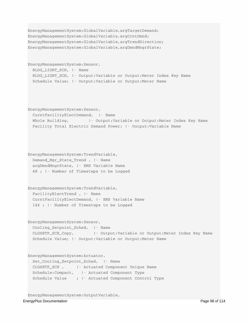
EnergyManagementSystem:GlobalVariable,argTargetDemand;EnergyManagementSystem:GlobalVariable,argCrntDmnd;EnergyManagementSystem:GlobalVariable,argTrendDirection;EnergyManagementSystem:GlobalVariable,argDmndMngrState;
EnergyManagementSystem:Sensor, BLDG_LIGHT_SCH, !- Name BLDG_LIGHT_SCH, !- Output:Variable or Output:Meter Index Key Name Schedule Value; !- Output:Variable or Output:Meter Name
EnergyManagementSystem:Sensor, CurntFacilityElectDemand, !- Name Whole Building, !- Output:Variable or Output:Meter Index Key Name Facility Total Electric Demand Power; !- Output:Variable Name
EnergyManagementSystem:TrendVariable, Demand_Mgr_State_Trend , !- Name argDmndMngrState, !- EMS Variable Name 48 ; !- Number of Timesteps to be Logged
EnergyManagementSystem:TrendVariable, FacilityElectTrend , !- Name CurntFacilityElectDemand, !- EMS Variable Name 144 ; !- Number of Timesteps to be Logged
EnergyManagementSystem:Sensor, Cooling_Setpoint_Sched, !- Name CLGSETP_SCH_Copy, !- Output:Variable or Output:Meter Index Key Name Schedule Value; !- Output:Variable or Output:Meter Name
EnergyManagementSystem:Actuator, Set_Cooling_Setpoint_Sched, !- Name CLGSETP_SCH , !- Actuated Component Unique Name Schedule:Compact, !- Actuated Component Type Schedule Value ; !- Actuated Component Control Type
EnergyManagementSystem:OutputVariable, Erl Cooling Setpoint [C], !- NameEnergyPlus Documentation Page 98 of 114

Erl Cooling Setpoint [C], !- Name Set_Cooling_Setpoint_Sched, !- EMS Variable Name Averaged , !- Type of Data in Variable ZoneTimestep; !- Update Frequency
Output:Variable, *, Erl Cooling Setpoint, Timestep;
EnergyManagementSystem:Actuator, Set_Basement_Lights, !- Name Basement_Lights , !- Actuated Component Unique Name Lights, !- Actuated Component Type Electric Power Level; !- Actuated Component Control Type
EnergyManagementSystem:InternalVariable, Basement_Lights , !- Name Basement_Lights , !- Internal Data Index Key Name Lighting Power Design Level ; !- Internal Data Type
EnergyManagementSystem:Actuator, Set_Core_bottom_Lights, !- Name Core_bottom_Lights , !- Actuated Component Unique Name Lights, !- Actuated Component Type Electric Power Level; !- Actuated Component Control TypeEnergyManagementSystem:InternalVariable, Core_bottom_Lights , !- Name Core_bottom_Lights , !- Internal Data Index Key Name Lighting Power Design Level ; !- Internal Data Type
<< Snipped remaining Lights Sensors and Actuators >>
Example 10. Plant Loop Override ControlProblem StatementA common occurrence in EnergyPlus central plant simulations is for a component to be designed well, butduring the course of an annual simulation, it is operated outside of its allowable region. This is due to thegoverning control strategies (operating schemes). These operation schemes may not have the intelligenceto say, turn off a cooling tower when the outdoor temperature is too low.
EnergyPlus Documentation Page 99 of 114
Within the EnergyPlus example files, the cooling tower offers warnings stating that the tower temperature isgoing below a low temperature limit. We should ask, can we use a simple EMS addition to an input file tooverride the loop and turn off the cooling tower to avoid these situations and therefore the warnings?
EMS Design DiscussionFor this example, we will start with the example file that is packaged with EnergyPlus calledEcoRoofOrlando.idf. This is one example of an input file where a cooling tower throws warnings due tooperating at too low of a temperature. Although the input file has many aspects related to zone and HVAC,we will only be interested in the loop containing the tower, which is a CondenserLoop named Chiller PlantCondenser Loop. The loop has a minimum loop temperature of 5 degrees Celsius, as specified by theCondenserLoop object.
In order to avoid these warnings and properly shut off the tower, EMS will be used to check the outdoortemperature and shut down the whole loop. Special care must be taken when manipulating plant andcondenser loops with EMS. The most robust way found is to both disable the loop equipment and alsooverride (turn off) the loop. Skipping either of these can cause mismatches where either components arestill expecting flow but the pump is not running, or the pump is trying to force flow through componentswhich are disabled. Either of these cases can cause unstable conditions and possibly fatal flow errors.
The outdoor air temperature must be checked in order to determine what the EMS needs to do at aparticular point in the simulation. This is handled by use of an EMS sensor monitoring the Outdoor DryBulb standard E+ output variable.
To manage the loop and pump, actuators are employed on both. The pump actuator is a mass flow rateoverride. This can be used to set the flow to zero, effectively shutting off the pump. The loop actuator is anon/off supervisory control, which allows you to “shut the entire loop down.” This actuator will not actuallyshut the loop down, it effectively empties the equipment availability list, so that there is no equipmentavailable to reject/absorb load on the supply side. If you use this actuator alone to “shut down the loop,”you may find that the pump is still flowing fluid around the loop, but the equipment will not be running.
The EMS calling point chosen is “ InsideHVACSystemIterationLoop,” so that the operation will be updatedevery time the plant loops are simulated.
The Erl program is quite simple for this case. If the outdoor dry bulb temperature goes below a certainvalue, the loop and pump actuators are set to zero. If the outdoor temperature is equal to or above thisvalue, the actuators are set to Null, relinquishing control back to the regular operation schemes. Inmodifying this specific input file it was found that the outdoor dry bulb temperature which removed thesewarnings was six degrees Celsius. We also create a custom output variable called “EMS Condenser FlowOverride On” to easily record when the overrides have occurred.
EMS Input ObjectsThe main input objects that implement this example of plant loop control are listed below and are includedin the example file called “EMSPlantLoopOverrideControl.idf.” The addition of the EMS objects properlyshuts down the loop as the outdoor temperature go below the transition value, and the simulation error fileshows no warnings for the tower outlet temperature.
EnergyManagementSystem:Sensor, OutdoorTemp, !- Name Environment, !- Output:Variable Index Key Name Site Outdoor Air Drybulb Temperature; !- Output:Variable NameEnergyPlus Documentation Page 100 of 114
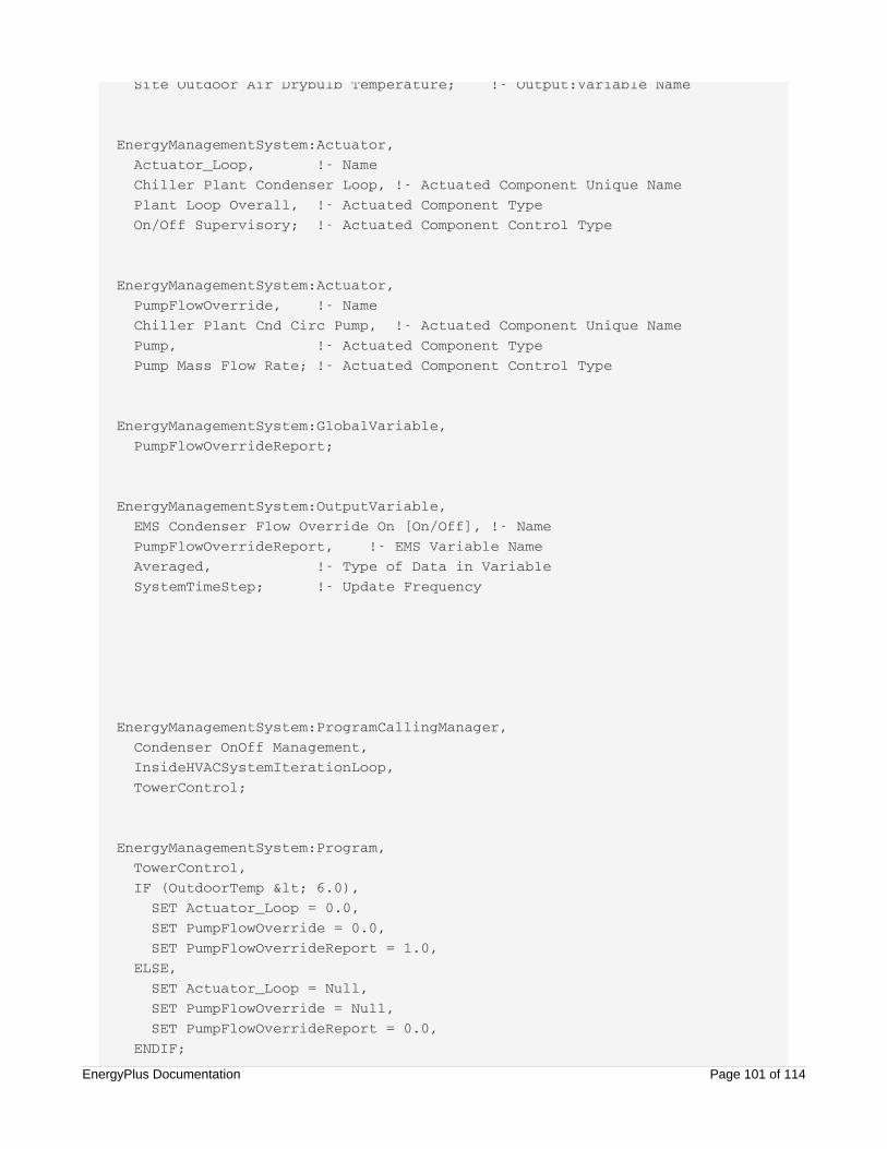
Site Outdoor Air Drybulb Temperature; !- Output:Variable Name
EnergyManagementSystem:Actuator, Actuator_Loop, !- Name Chiller Plant Condenser Loop, !- Actuated Component Unique Name Plant Loop Overall, !- Actuated Component Type On/Off Supervisory; !- Actuated Component Control Type
EnergyManagementSystem:Actuator, PumpFlowOverride, !- Name Chiller Plant Cnd Circ Pump, !- Actuated Component Unique Name Pump, !- Actuated Component Type Pump Mass Flow Rate; !- Actuated Component Control Type
EnergyManagementSystem:GlobalVariable, PumpFlowOverrideReport;
EnergyManagementSystem:OutputVariable, EMS Condenser Flow Override On [On/Off], !- Name PumpFlowOverrideReport, !- EMS Variable Name Averaged, !- Type of Data in Variable SystemTimeStep; !- Update Frequency
EnergyManagementSystem:ProgramCallingManager, Condenser OnOff Management, InsideHVACSystemIterationLoop, TowerControl;
EnergyManagementSystem:Program, TowerControl, IF (OutdoorTemp < 6.0), SET Actuator_Loop = 0.0, SET PumpFlowOverride = 0.0, SET PumpFlowOverrideReport = 1.0, ELSE, SET Actuator_Loop = Null, SET PumpFlowOverride = Null, SET PumpFlowOverrideReport = 0.0, ENDIF;
EnergyPlus Documentation Page 101 of 114

Output:Variable, *, EMS Condenser Flow Override On, Hourly;
Example 11. Performance Curve ResultOverrideProblem StatementThe output of EnergyPlus performance curves (or tables) can be modified as necessary to simulatehardware or controls that cannot be accurately realized using a single performance curve. This exampledescribes a method for modifying the capacity of a DX cooling coil via the DX coil objects Total CoolingCapacity Function of Temperature performance curve object.
A particular manufacturer controls the DX cooling coil such that the capacity of the coil changes at 31°Coutdoor air dry-bulb temperature. The following EMS program logic will calculate alternate inputs for coolingcoil capacity and over-write the existing performance curve results.
EMS Design DiscussionFor this example, we will start with the equation for cooling capacity of the DX coil object (ref.Coil:Cooling:DX:SingleSpeed). From the engineering reference, the equation used to calculate the coolingcapacity is:
The first term (Twb,i) refers to the cooling coil inlet air wet-bulb temperature and the second (Tc,i) refers tothe outdoor condenser inlet air dry-bulb temperature. Using the EMS, a new total capacity as a function oftemperature value will be calculated and used during the simulation. The Energyplus input objects for thecooling coil capacity curve, the associated outdoor air mixer object, and the original cooling capacityperformance curve are shown here.
TotCapTempModFac = a+ b ( ) + c ( ) + d( ) + e( ) + f ( )( )Twb,i Twb,i Tc,i Tc,i Twb,i Tc,i (3)
EnergyPlus Documentation Page 102 of 114
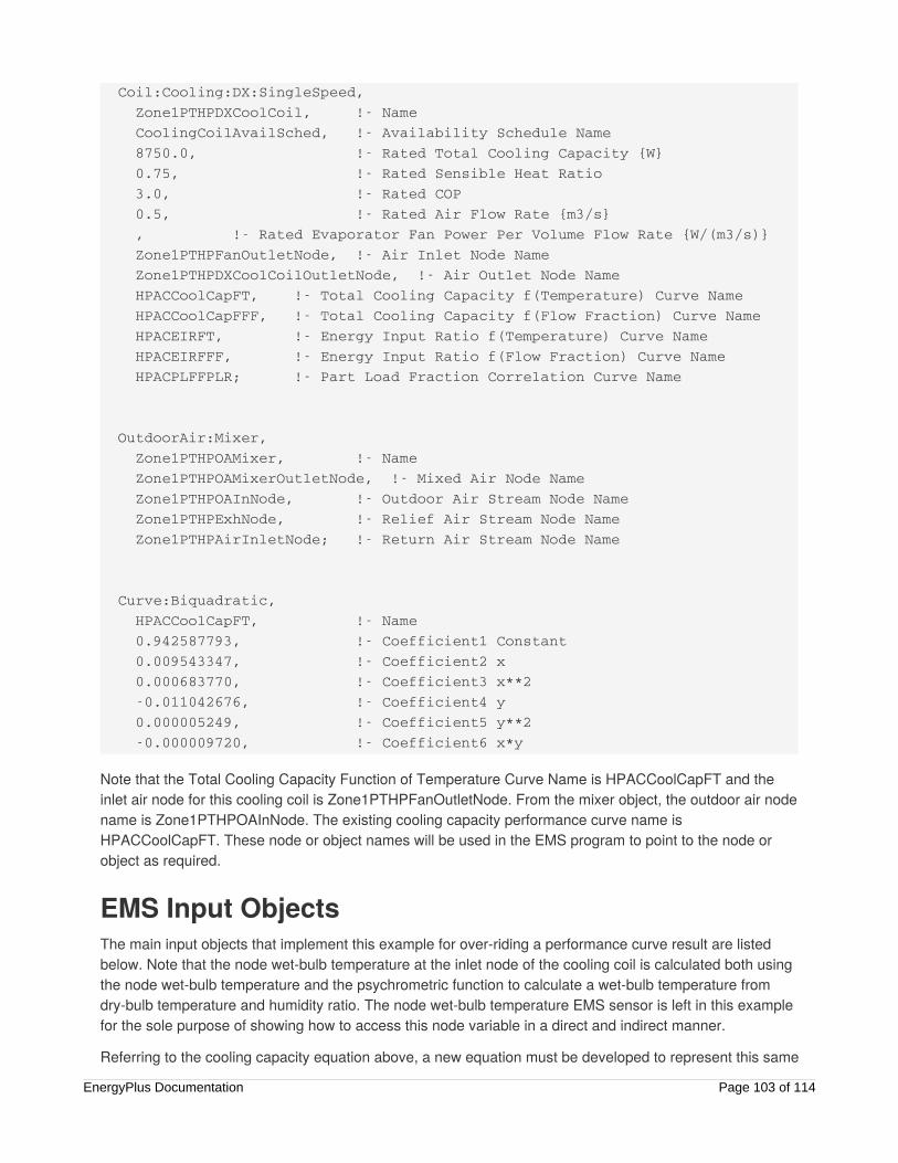
Coil:Cooling:DX:SingleSpeed, Zone1PTHPDXCoolCoil, !- Name CoolingCoilAvailSched, !- Availability Schedule Name 8750.0, !- Rated Total Cooling Capacity {W} 0.75, !- Rated Sensible Heat Ratio 3.0, !- Rated COP 0.5, !- Rated Air Flow Rate {m3/s} , !- Rated Evaporator Fan Power Per Volume Flow Rate {W/(m3/s)} Zone1PTHPFanOutletNode, !- Air Inlet Node Name Zone1PTHPDXCoolCoilOutletNode, !- Air Outlet Node Name HPACCoolCapFT, !- Total Cooling Capacity f(Temperature) Curve Name HPACCoolCapFFF, !- Total Cooling Capacity f(Flow Fraction) Curve Name HPACEIRFT, !- Energy Input Ratio f(Temperature) Curve Name HPACEIRFFF, !- Energy Input Ratio f(Flow Fraction) Curve Name HPACPLFFPLR; !- Part Load Fraction Correlation Curve Name
OutdoorAir:Mixer, Zone1PTHPOAMixer, !- Name Zone1PTHPOAMixerOutletNode, !- Mixed Air Node Name Zone1PTHPOAInNode, !- Outdoor Air Stream Node Name Zone1PTHPExhNode, !- Relief Air Stream Node Name Zone1PTHPAirInletNode; !- Return Air Stream Node Name
Curve:Biquadratic, HPACCoolCapFT, !- Name 0.942587793, !- Coefficient1 Constant 0.009543347, !- Coefficient2 x 0.000683770, !- Coefficient3 x**2 -0.011042676, !- Coefficient4 y 0.000005249, !- Coefficient5 y**2 -0.000009720, !- Coefficient6 x*y
Note that the Total Cooling Capacity Function of Temperature Curve Name is HPACCoolCapFT and theinlet air node for this cooling coil is Zone1PTHPFanOutletNode. From the mixer object, the outdoor air nodename is Zone1PTHPOAInNode. The existing cooling capacity performance curve name isHPACCoolCapFT. These node or object names will be used in the EMS program to point to the node orobject as required.
EMS Input ObjectsThe main input objects that implement this example for over-riding a performance curve result are listedbelow. Note that the node wet-bulb temperature at the inlet node of the cooling coil is calculated both usingthe node wet-bulb temperature and the psychrometric function to calculate a wet-bulb temperature fromdry-bulb temperature and humidity ratio. The node wet-bulb temperature EMS sensor is left in this examplefor the sole purpose of showing how to access this node variable in a direct and indirect manner.
Referring to the cooling capacity equation above, a new equation must be developed to represent this same
EnergyPlus Documentation Page 103 of 114
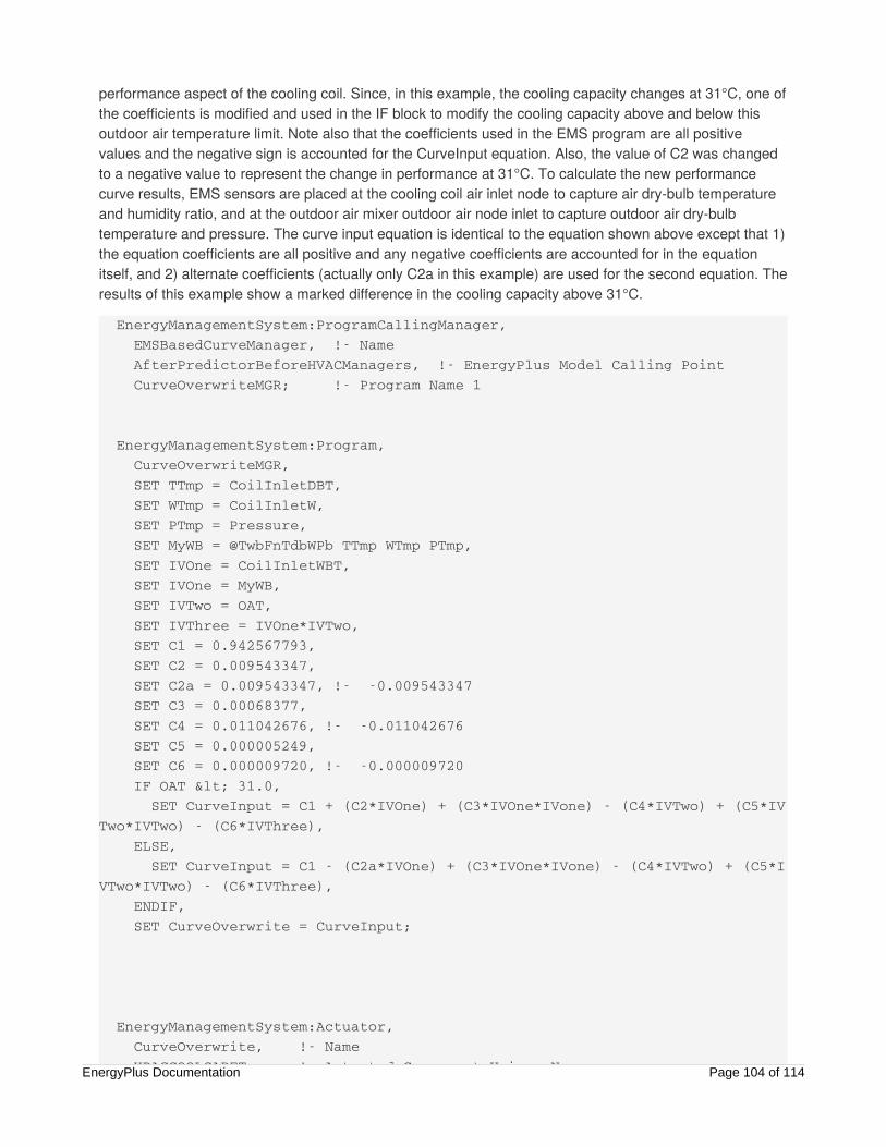
performance aspect of the cooling coil. Since, in this example, the cooling capacity changes at 31°C, one ofthe coefficients is modified and used in the IF block to modify the cooling capacity above and below thisoutdoor air temperature limit. Note also that the coefficients used in the EMS program are all positivevalues and the negative sign is accounted for the CurveInput equation. Also, the value of C2 was changedto a negative value to represent the change in performance at 31°C. To calculate the new performancecurve results, EMS sensors are placed at the cooling coil air inlet node to capture air dry-bulb temperatureand humidity ratio, and at the outdoor air mixer outdoor air node inlet to capture outdoor air dry-bulbtemperature and pressure. The curve input equation is identical to the equation shown above except that 1)the equation coefficients are all positive and any negative coefficients are accounted for in the equationitself, and 2) alternate coefficients (actually only C2a in this example) are used for the second equation. Theresults of this example show a marked difference in the cooling capacity above 31°C.
EnergyManagementSystem:ProgramCallingManager, EMSBasedCurveManager, !- Name AfterPredictorBeforeHVACManagers, !- EnergyPlus Model Calling Point CurveOverwriteMGR; !- Program Name 1
EnergyManagementSystem:Program, CurveOverwriteMGR, SET TTmp = CoilInletDBT, SET WTmp = CoilInletW, SET PTmp = Pressure, SET MyWB = @TwbFnTdbWPb TTmp WTmp PTmp, SET IVOne = CoilInletWBT, SET IVOne = MyWB, SET IVTwo = OAT, SET IVThree = IVOne*IVTwo, SET C1 = 0.942567793, SET C2 = 0.009543347, SET C2a = 0.009543347, !- -0.009543347 SET C3 = 0.00068377, SET C4 = 0.011042676, !- -0.011042676 SET C5 = 0.000005249, SET C6 = 0.000009720, !- -0.000009720 IF OAT < 31.0, SET CurveInput = C1 + (C2*IVOne) + (C3*IVOne*IVone) - (C4*IVTwo) + (C5*IVTwo*IVTwo) - (C6*IVThree), ELSE, SET CurveInput = C1 - (C2a*IVOne) + (C3*IVOne*IVone) - (C4*IVTwo) + (C5*IVTwo*IVTwo) - (C6*IVThree), ENDIF, SET CurveOverwrite = CurveInput;
EnergyManagementSystem:Actuator, CurveOverwrite, !- Name HPACCOOLCAPFT, !- Actuated Component Unique NameEnergyPlus Documentation Page 104 of 114

HPACCOOLCAPFT, !- Actuated Component Unique Name Curve, !- Actuated Component Type Curve Result; !- Actuated Component Control Type
EnergyManagementSystem:Sensor, ActualCurve, !- Name HPACCOOLCAPFT, !- Output:Variable or Output:Meter Index Key Name Performance Curve Output Value; !- Output:Variable or Output:Meter Name
EnergyManagementSystem:Sensor, CoilInletWBT, !- Name Zone1PTHPFanOutletNode, !- Output:Variable or Output:Meter Index Key Name System Node Wetbulb Temperature; !- Output:Variable or Output:Meter Name
EnergyManagementSystem:Sensor, Pressure, !- Name Zone1PTHPOAInNode, !- Output:Variable or Output:Meter Index Key Name System Node Pressure ; !- Output:Variable or Output:Meter Name
EnergyManagementSystem:Sensor, CoilInletDBT, !- Name Zone1PTHPFanOutletNode, !- Output:Variable or Output:Meter Index Key Name System Node Temperature; !- Output:Variable or Output:Meter Name
EnergyManagementSystem:Sensor, CoilInletW, !- Name Zone1PTHPFanOutletNode, !- Output:Variable or Output:Meter Index Key Name System Node Humidity Ratio; !- Output:Variable or Output:Meter Name
EnergyManagementSystem:Sensor, OAT, !- Name Zone1PTHPOAInNode, !- Output:Variable or Output:Meter Index Key Name System Node Temperature; !- Output:Variable or Output:Meter Name
EnergyManagementSystem:OutputVariable, ERLCurveValue, ! Name ActualCurve, ! EMS Variable Name Averaged, ! Type of Data in Variable ZoneTimeStep ; ! Update Frequency
EnergyManagementSystem:OutputVariable, NewCurveValue, ! NameEnergyPlus Documentation Page 105 of 114

NewCurveValue, ! Name CurveInput, ! EMS Variable Name Averaged, ! Type of Data in Variable ZoneTimeStep ; ! Update Frequency
Output:EnergyManagementSystem, Verbose, !- Actuator Availability Dictionary Reporting Verbose, !- Internal Variable Availability Dictionary Reporting Verbose; !- EMS Runtime Language Debug Output Level
Output:Variable, *, ERLCurveValue, Hourly;
Output:Variable, HPACCOOLCAPFT, Performance Curve Output Value,Hourly; Output:Variable, HPACCOOLCAPFT, Performance Curve Input Variable 1 Value,Hourly; Output:Variable, HPACCOOLCAPFT, Performance Curve Input Variable 2 Value,Hourly; Output:Variable, Zone1PTHPFanOutletNode, System Node Wetbulb Temperature, Hourly;
Figure 4. Results of Performance Curve Override
EnergyPlus Documentation Page 106 of 114

Example 12. Variable Refrigerant FlowSystem OverrideProblem StatementThe variable refrigerant flow heat pump air conditioner has several available thermostat control options.These operation control schemes may not provide the type of control desired. How can we use a simpleEMS addition to an input file that can override the specified thermostat control logic and set an alternatemode of operation?
EMS Design DiscussionDepending on the type of thermostat control logic, the EnergyPlus program will review the loads in eachzone, the number of zones in cooling or heating, the deviation from set point temperature, etc. to determinethe mode of operation for the heat pump condenser. Alternate control logic may be developed to moreaccurately reflect the operation of a specific manufacturers product, or investigate other control techniques.This control logic may be added to an input file and used as the operating control logic of the heat pump.
This simple example shows how to use EMS actuators to SET the operating mode and cause a specificterminal unit to operate at a specified part-load ratio (PLR). When setting the terminal unit PLR, theterminal unit will turn on only if the condenser is allowed to operate according to the minimum andmaximum outdoor temperature limits.
EMS Input ObjectsThe main input objects that implement this example are the variable refrigerant flow actuators that controlthe VRF system and specific terminal unit. Note that the terminal unit PLR can be controlled withoutcontrolling the mode of the VRF condenser, however, the specific terminal unit will operate in whatevermode the existing operation control scheme chooses. This example program simply “sets” the operatingmode and PLR, other more complex control algorithms can be developed by the user as needed.
Output:EnergyManagementSystem, Verbose, !- Actuator Availability Dictionary Reporting Verbose, !- Internal Variable Availability Dictionary Reporting Verbose; !- EMS Runtime Language Debug Output Level
EnergyManagementSystem:ProgramCallingManager, VRF OnOff Management, !- Name InsideHVACSystemIterationLoop, !- EnergyPlus Model Calling Point VRFControl; !- Program Name 1
EnergyManagementSystem:Program, VRFControl, !- Name SET VRF_Actuator_OnOff = VRF_Status_Heating, !- Program Line 2 SET VRF_TerminalUnit1_PLR = 0.5;
EnergyPlus Documentation Page 107 of 114

SET VRF_TerminalUnit1_PLR = 0.5;
EnergyManagementSystem:Actuator, VRF_Actuator_OnOff, !- Name VRF Heat Pump, !- Actuated Component Unique Name Variable Refrigerant Flow Heat Pump, !- Actuated Component Type Operating Mode; !- Actuated Component Control Type
EnergyManagementSystem:Actuator, VRF_TerminalUnit1_PLR, !- Name TU1, !- Actuated Component Unique Name Variable Refrigerant Flow Terminal Unit, !- Actuated Component Type Part Load Ratio; !- Actuated Component Control Type
EnergyManagementSystem:OutputVariable, Erl VRF Control Status, !- Name VRF_Actuator_OnOff, !- EMS Variable Name Averaged, !- Type of Data in Variable SystemTimeStep; !- Update Frequency
Output:Variable,*,Erl VRF Control Status, detailed; Output:Variable,*,VRF Heat Pump Operating Mode, detailed; Output:Variable,*,Cooling Coil Runtime Fraction, detailed; Output:Variable,*,Heating Coil Runtime Fraction, detailed;
EnergyManagementSystem:ProgramCallingManager, Init VRF Control Mode Constants, !- Name BeginNewEnvironment, !- EnergyPlus Model Calling Point InitializeVRFControlModes; !- Program Name 1
EnergyManagementSystem:Program, InitializeVRFControlModes, !- Name Set VRF_Status_Off = 0.0, !- Program Line 1 Set VRF_Status_Cooling = 1.0, !- Program Line 2 Set VRF_Status_Heating = 2.0; !- Program Line 3
EnergyManagementSystem:GlobalVariable, VRF_Status_Off, !- Erl Variable 1 Name VRF_Status_Cooling, !- Erl Variable 2 Name VRF_Status_Heating; !- Erl Variable 3 Name
EnergyPlus Documentation Page 108 of 114

Example 13. Surface Construction Actuatorfor Thermochromic WindowProblem StatementThere are a variety of novel new technologies for dynamic thermal envelopes that are the subject ofresearch and development. Can we use EMS to investigate dynamic envelope technologies?
EMS Design DiscussionAs an example, we will show how to use the EMS to replicate a thermochromic window. EnergyPlusalready has a dedicated model for thermochromic windows (see the input objectWindowMaterial:GlazingGroup:Thermochromic) that is demonstrated in the example file calledThermochromicWindow.idf. For this EMS example we will start with that file, remove theWindowMaterial:GlazingGroup:Thermochromic and emulate the thermochromic window using the EMSactuator called “Surface” with the control type “Construction State.”
The first step is to create the individual Construction objects that will represent the individual states. Theoriginal thermochromic example file already includes a series of WindowMaterial:Glazing input objects thatcorrespond to the properties of the thermochromic glazing at different temperatures. These glazing layersare then used in a series of Construction objects that represent the entire glazing system description ateach temperature “state.” Separate EnergyManagementSystem:ConstructionIndexVariable objects arethen added for each Construction to setup Erl variables that point to each construction.
The control algorithm is very simple. The temperature of the glazing is used in a long IF-ELSEIF-ELSE-ENDIF block to select the appropriate construction to assign the surface. In this case the nativethermochromic model has an important advantage in that the dedicated model can access the temperatureof the middle pane in a triple glazed window whereas the EMS model can only access the temperature ofthe outside pane or the inside pane. Here we use the temperature of the outside face of the surfacebecause it is closer to the temperature of the middle pane (which can be much higher when in direct sun).
EMS Input ObjectsThe main input objects that implement this example of EMS-based thermochromic glazing system are listedbelow. The surface called “Perimeter_ZN_1_wall_south_Window_1” is the one being actuated by EMS andwe can observe the outcomes of the override by reporting the output variable called Surface ConstructionIndex. See the example file called EMSThermochromicWindow.idf.
Construction, TCwindow_25, !- Name Clear3PPG, !- Outside Layer AIR 3MM, !- Layer 2 WO18RT25, !- Layer 3 AIR 8MM, !- Layer 4 SB60Clear3PPG; !- Layer 5
EnergyManagementSystem:ConstructionIndexVariable,EnergyPlus Documentation Page 109 of 114
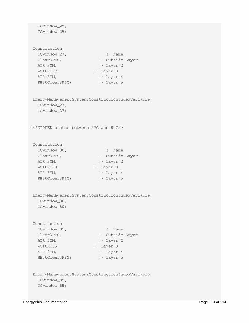
TCwindow_25, TCwindow_25;
Construction, TCwindow_27, !- Name Clear3PPG, !- Outside Layer AIR 3MM, !- Layer 2 WO18RT27, !- Layer 3 AIR 8MM, !- Layer 4 SB60Clear3PPG; !- Layer 5
EnergyManagementSystem:ConstructionIndexVariable, TCwindow_27, TCwindow_27;
<<SNIPPED states between 27C and 80C>>
Construction, TCwindow_80, !- Name Clear3PPG, !- Outside Layer AIR 3MM, !- Layer 2 WO18RT80, !- Layer 3 AIR 8MM, !- Layer 4 SB60Clear3PPG; !- Layer 5
EnergyManagementSystem:ConstructionIndexVariable, TCwindow_80, TCwindow_80;
Construction, TCwindow_85, !- Name Clear3PPG, !- Outside Layer AIR 3MM, !- Layer 2 WO18RT85, !- Layer 3 AIR 8MM, !- Layer 4 SB60Clear3PPG; !- Layer 5
EnergyManagementSystem:ConstructionIndexVariable, TCwindow_85, TCwindow_85;
EnergyPlus Documentation Page 110 of 114

EnergyManagementSystem:Sensor, Win1_Tout, Perimeter_ZN_1_wall_south_Window_1, Surface Outside Face Temperature;
EnergyManagementSystem:Actuator, Win1_Construct, Perimeter_ZN_1_wall_south_Window_1, Surface, Construction State;
EnergyManagementSystem:ProgramCallingManager, My thermochromic window emulator, BeginTimestepBeforePredictor, ZN_1_wall_south_Window_1_Control;
EnergyManagementSystem:Program, ZN_1_wall_south_Window_1_Control, IF Win1_Tout <= 26.0 , Set Win1_Construct = TCwindow_25, ELSEIF Win1_Tout <= 28.0 , SEt Win1_Construct = TCwindow_27, ELSEIF Win1_Tout <= 30.0 , SET Win1_Construct = TCwindow_29, ELSEIF Win1_Tout <= 32.0 , SET Win1_Construct = TCwindow_31, ELSEIF Win1_Tout <= 34.0 , SET Win1_Construct = TCwindow_33, ELSEIF Win1_Tout <= 36.0 , SET Win1_Construct = TCwindow_35, ELSEIF Win1_Tout <= 38.0 , SET Win1_Construct = TCwindow_37, ELSEIF Win1_Tout <= 40.0 , SET Win1_Construct = TCwindow_39, ELSEIF Win1_Tout <= 42.0 , SET Win1_Construct = TCwindow_41, ELSEIF Win1_Tout <= 44.0 , SET Win1_Construct = TCwindow_43, ELSEIF Win1_Tout <= 47.5 , SET Win1_Construct = TCwindow_45, ELSEIF Win1_Tout <= 52.5 , SET Win1_Construct = TCwindow_50, ELSEIF Win1_Tout <= 57.5 , SET Win1_Construct = TCwindow_55, ELSEIF Win1_Tout <= 62.5 , SET Win1_Construct = TCwindow_60,
EnergyPlus Documentation Page 111 of 114

ELSEIF Win1_Tout <= 67.5 , SET Win1_Construct = TCwindow_65, ELSEIF Win1_Tout <= 72.5 , SET Win1_Construct = TCwindow_70, ELSEIF Win1_Tout <= 77.5 , SET Win1_Construct = TCwindow_75, ELSEIF Win1_Tout <= 82.5 , SET Win1_Construct = TCwindow_80, ELSE , SET Win1_Construct = TCwindow_85, ENDIF;
Output:Variable, Perimeter_ZN_1_wall_south_Window_1, Surface Construction Index, timestep;
Debugging EMS ProgramsThis section discusses approaches to debugging Erl programs. As you develop your own programs, youwill need to identify and correct coding problems. The task of debugging an Erl program is challenging.Compared to most programming, with integrated development environments and sophisticated debugginginterfaces, the Erl programmer has only rudimentary tools available for debugging. If you have some type ofdeveloper license and EnergyPlus source code, you could debug Erl programs inside a full-featureddebugging environment (such as IVF integrated into VS9). But this is only for extremely advanced usersand developers implementing EMS related code inside EnergyPlus. Most users’ EMS should have littleneed to deal with compilers and development environments, because enough information is produced byEnergyPlus when it runs their Erl programs. This section examines output related to EMS in an effort to helpyou debug your Erl programs.
ERR FileA key output file to review is the ERR file (eplusout.err), the one with the “.err” file extension. This is thecommon error file for all of EnergyPlus, and many EMS-related errors will appear there. The file mightcontain critical problems that arose while the Erl programs were being read in and processed. Although theEDD file will likely be the focus of most debugging, remember the ERR file. Also, sometimes no EDD file isproduced from a run. This occurs when problems are captured early during input processing and theprogram fatals out before an Erl program is run. Depending on the run manager you use to executeEnergyPlus, the EDD file may be from a previous run, so check the file creation times for ERR and EDD.
An especially important error revealed in the ERR file is truncation from too long input. Each program line inErl is limited to 100 characters. (It becomes useful to keep variable names shorter in Erl because the linelength limit can be onerous.) If there are more than 100 characters, the program truncates the line to thefirst 100. This will often throw a severe error that halts because the truncated line is not a valid statement.But an unlucky truncation may form a viable line of code and the program will run. Truncation of any Erlprogram line is surely a bad thing, so it is important to check the ERR file.
EnergyPlus Documentation Page 112 of 114

EDD FileIf the Erl programs are processed and start running, the EDD becomes a primary source of information fordebugging. The EDD file is the output file associated only with the EMS. When a line of Erl code isexecuted, and full trace is selected, the program will output records that are useful for debugging.
It is very important to be careful with the EDD file. There are options to control how verbose the EDD filebecomes with modes such as only the errors or a full trace. The full trace option should be used with carebecause a full line-by-line trace of EMS program execution for an annual run can easily create an enormousfile that is too large for most computer systems.
Line TraceYou can use the EDD file to examine the execution of every line of code. If you request a verbose level ofdebugging output in the Output:EnergyManagementSystem input object, the EDD file will contain a seriesof text records that trace the execution of each line of Erl code. Traces contain the name of the program,the program line number, the text of the line, the result returned by executing the line (if any), and atimestamp that indicates when it was executed during the environment period. Note that the EDD file is onlyproduced if you have EMS/Erl programs in your input file.
An example of a single trace follows. This is one record, or single line of text from one of the traces in anEDD file.
VAV1MIXEDAIRMANAGERS,Line 1,SET VAV_1_COOLC_SETPOINT = SEASONAL_RESET_SAT_SCHED - ( T_VAV1FANOUT - T_VAV1FANIN),13.0000000000000, During Warmup, Occurrence info=CHICAGO IL USA TMY2-94846 WMO\#=725300, 01/01 18:30 - 18:45
Each block of text is separated by comma, so the trace information could be read into a spreadsheet andformatted to columns using comma separation.
“VAV1MIXEDAIRMANAGERS” is the name of a user-defined Erl Program.
“Line 1” indicates that this trace is from the first line of the Erl program called VAV1MIXEDAIRMANAGERS.
The next block of text, “SET VAV_1_COOLC_SETPOINT = SEASONAL_RESET_SAT_SCHED - (T_VAV1FANOUT - T_VAV1FANIN)” is the Erl program statement contained at Line 1 in the Erl programcalled VAV1MIXEDAIRMANAGERS.
The value “13.0000000000000” is the result of this particular SET statement. The value of 13.0 has beenassigned to the variable called VAV_1_COOLC_SETPOINT.
The next block of text “During Warmup” indicates that the line was executed while the simulation was in awarm up phase. (Warmup happens during the beginning of each environment period to precondition themodel’s transients with the conditions of the first day.)
The next block of text “Occurrence info=CHICAGO IL USA TMY2-94846 WMO#=725300” indicates theenvironment period being simulated. This is a weather-file-based RunPeriod for Chicago using TMY2 datasource associated with weather station number 725300.
The last block of text “01/01 18:30 - 18:45” is the date and time of day for the simulation timestep when theErl program line was executed.
EnergyPlus Documentation Page 113 of 114

Debugging StrategiesThis section attempts to provide some debugging tips.
There is no debugging environment, so the main way to obtain information is to use verbose mode andtrace each line.
Say, for example, we are trying to debug the following line:
ELSEIF (Hour >= 5) && (Hour < 19) && (DayOfWeek >=2) && (DayOfWeek <=6) ,
The line trace, shown next, shows only the result of the logical condition, i.e., 0.0 (highlighted) if overall it isfalse or 1.0 if overall it is true.
MYCOMPUTEDHEATINGSETPOINTPROG,Line 10,ELSEIF (HOUR >= 5) && (HOUR < 19) && (DAYOFWEEK >=2) && (DAYOFWEEK <=6),0.0, Occurrence info=CHICAGO IL USA TMY2-94846 WMO\#=725300, 09/23 10:20 - 10:30
To debug what is going on with the individual terms in the logical expression, we can add some otherwiseuseless statements so line traces contain an echo of the current values of the HOUR and DAYOFWEEKbuilt-in variables. So if we add the following lines before the start of the IF block,
Set locHour = Hour, ! echo out for debug Set locDay = DayOfWeek, ! echo out for debug
We will see the values that Hour and DayOfWeek contain in the debug output. The local variables Erlvariables locHour and locDay do not need to be used for anything, but by adding these Erl statements wecan glean debugging insights.
The line of Erl code is switched to all uppercase on input, so the line trace differs from the input file in thatall characters are capitalized. If the input file was developed using a CamelCase convention, it may bemuch more difficult to read in the line trace output. Thus, the underscore character “_” may be a moreuseful convention for inputting Erl code because it will be more readable in the debugging traces.
Get Help | More Information
EnergyPlus is developed in collaboration by NREL, LBNL, ORNL, and PNNL.
NREL is a National Laboratory of the U.S. Department of Energy, Office of Energy Efficiency and Renewable Energy, operatedby the Alliance for Sustainable Energy, LLC.
Back to Top
EnergyPlus Documentation Page 114 of 114