Embed Size (px)
Citation preview
AudioCodes™ Element Management System (EMS) and Session Experience Manager (SEM)
EMS and SEM
Product Description Version 6.8


Product Description Contents
Version 6.8 3 February 2014
Table of Contents 1 Introducing AudioCodes’ Element Management System (EMS) ..................... 9
1.1 Characteristics ................................................................................................................. 9 1.1.1 EMS System Characteristics ................................................................................. 9 1.1.2 Versatile System ................................................................................................... 9 1.1.3 FCAPS .................................................................................................................. 9 1.1.4 Open Standard Design ........................................................................................ 10 1.1.5 Private Labeling................................................................................................... 10
1.2 Architecture Overview ................................................................................................... 10 1.2.1 EMS Client Login on all EMS server Network Interfaces ...................................... 11
1.3 Specifications ................................................................................................................ 12 1.4 Supported VoIP Equipment ........................................................................................... 16
2 Fault Management ............................................................................................. 25
2.1 Alarm Processing .......................................................................................................... 25 2.2 Alarm Context-Based View............................................................................................ 26 2.3 Graphical Alarm Reports ............................................................................................... 26 2.4 Carrier-Grade Alarms System between the EMS and the Media Gateways ................ 27 2.5 Alarm Priorities .............................................................................................................. 27 2.6 Automatic Alarms and Events Clearing ........................................................................ 27 2.7 Traps Forwarding to the NMS ....................................................................................... 27 2.8 Save alarms into .csv file .............................................................................................. 27 2.9 Alarm Types ................................................................................................................... 28 2.10 Alarms Actions .............................................................................................................. 28 2.11 Detailed Information ...................................................................................................... 28 2.12 Active and History Alarm Printing ................................................................................ 28 2.13 Searching and Filtering Options ................................................................................... 28 2.14 Change Alarm Browser View and Level ....................................................................... 28 2.15 Audio Indication on Receipt of Alarms ......................................................................... 29 2.16 Security .......................................................................................................................... 29 2.17 Alarm Archiving (History) .............................................................................................. 29
3 Session Experience Manager (SEM) ................................................................ 31
3.1 SEM Data Views ............................................................................................................. 32
4 Entity Management and Configuration ............................................................ 35
4.1 Automatic Gateway Software Version Detection ......................................................... 35 4.2 Media Gateway Status Summary .................................................................................. 35 4.3 Real-Time Color-Coded Media Gateway View .............................................................. 37 4.4 One-Click Access to Element Provisioning and Actions ............................................. 37 4.5 Modular Workflow Process ........................................................................................... 38
4.5.1 Navigation Desktop ............................................................................................. 38 4.5.2 Configuration Desktop ......................................................................................... 38 4.5.3 Alarms Desktop ................................................................................................... 38 4.5.4 Performance Desktop .......................................................................................... 39 4.5.5 Context-Sensitive Behavior .................................................................................. 39
4.6 Media Gateway Provisioning ......................................................................................... 40 4.6.1 Provisioning Types .............................................................................................. 41 4.6.2 Provisioning Frame - HA Indication ...................................................................... 41 4.6.3 Color - Coding ..................................................................................................... 41 4.6.4 Export / Import / Save Provisioning Data .............................................................. 41 4.6.5 Parameters Search.............................................................................................. 41 4.6.6 Media Gateway Offline Configuration ................................................................... 41

EMS and SEM
Product Description 4 Document #: LTRT-94017
4.6.7 Configuration Upload and Download .................................................................... 42 4.6.8 Capability to Save and Restore Gateway Configuration ....................................... 42 4.6.9 Upload INI file from the Gateway ......................................................................... 42 4.6.10 Security ............................................................................................................... 42
4.7 Media Gateways Maintenance Actions ......................................................................... 43 4.7.1 CPE and Blades .................................................................................................. 43
4.7.1.1 Software Upgrade and Regional Files Distribution ................................. 43 4.7.1.2 Save Configuration into Flash Memory .................................................. 43 4.7.1.3 Download INI file to Device ................................................................... 43 4.7.1.4 Configuration Data file Download and Upload Support .......................... 44 4.7.1.5 Multiple Gateways Lock / Unlock........................................................... 44 4.7.1.6 Resetting a Gateway ............................................................................ 44 4.7.1.7 Actions on Multiple MGs in one command ............................................. 44
4.7.2 Mediant 5000, Mediant 8000 Maintenance Actions .............................................. 44 4.7.2.1 Element Provisioing and Actions in Once .............................................. 45 4.7.2.2 Online Software Upgrade Wizard .......................................................... 45 4.7.2.3 Backup / Restore of the Media Gateway Configuration .......................... 45 4.7.2.4 GW Log Files Collection ....................................................................... 45 4.7.2.5 TP INI file Collection ............................................................................. 45 4.7.2.6 Move TP Board ..................................................................................... 45
5 Performance Management ............................................................................... 47
5.1 Alarm Severity and Gateway/Board/Channel Distribution Summary Screens ............ 48 5.2 Real-Time Performance Monitoring – Pre-defined Graphs .......................................... 49 5.3 Customized Real-Time and History (Background) Graphs .......................................... 49
5.3.1 Real-Time Graphs ............................................................................................... 50 5.3.2 History (Background) Performance Monitoring ..................................................... 50
5.4 Aggregated PMs ............................................................................................................ 50 5.5 Performance Thresholds ............................................................................................... 50
6 Security Management ....................................................................................... 51
6.1 FIPS Compliance ........................................................................................................... 51 6.2 Network Communication Security ................................................................................ 52
6.2.1 EMS Client <-> EMS Server ................................................................................ 53 6.2.2 EMS Server <-> Mediant 5000/Mediant 8000 Media Gateways ............................ 53 6.2.3 EMS Server <-> CPE and MediaPack.................................................................. 53 6.2.4 Media Gateways Access Control ......................................................................... 53
6.3 EMS Operator Authentication and Authorization ......................................................... 54 6.3.1 Centralized RADIUS TACACS+ or LDAP Servers User Profile ............................. 55 6.3.2 EMS Application User Profile ............................................................................... 56
6.3.2.1 EMS User Management: Session Inactivity Timer ................................. 56 6.3.2.2 EMS User Management: User Accounts Inactivity Timer ....................... 56 6.3.2.3 EMS User Security Levels .................................................................... 57
6.3.3 Multi-Tenancy for Operators ................................................................................ 57 6.3.3.1 Login Information Display...................................................................... 58
6.3.4 Integration with CAC Card ................................................................................... 58 6.3.5 Actions Journal .................................................................................................... 59
7 Virtualized EMS Server ..................................................................................... 61
8 EMS Server Management ................................................................................. 63
8.1 EMS Server High Availability (HA) ................................................................................ 63 8.2 EMS Server File System Security and Maintenance .................................................... 63
8.2.1 EMS Server File Integrity Checking ..................................................................... 63 8.2.2 Disk Array Configuration-RAID-0 on HP ProLiant DL360p Gen8 Servers ............. 63 8.2.3 Syslog and Debug Recording .............................................................................. 63

Product Description Contents
Version 6.8 5 February 2014
9 Northbound Interface ........................................................................................ 65
List of Figures Figure 1-1: EMS Architecture ............................................................................................................ 11 Figure 2-1: Alarm Browser in EMS Main Screen ................................................................................ 25 Figure 2-2: Graphical Alarm Reports ................................................................................................. 26 Figure 2-3: Alarms History ................................................................................................................. 29 Figure 3-1: SEM Map View ............................................................................................................... 31 Figure 4-1: Mediant 8000 Media Gateway 6310 Status Pane............................................................. 35 Figure 4-2: Mediant 5000 Media Gateway 6310 Status Pane............................................................. 36 Figure 4-3: Mediant 5000 8410 Status Pane ...................................................................................... 36 Figure 4-4: Mediant 3000 Status Pane .............................................................................................. 36 Figure 4-5: Mediant 800 MSBG Status Pane .................................................................................... 36 Figure 4-6: Mediant 1000 Status Pane .............................................................................................. 36 Figure 4-7: Mediant 2000 Status Pane .............................................................................................. 37 Figure 4-8: MediaPack Media Gateway Status Pane ......................................................................... 37 Figure 4-9: EMS Toolbar ................................................................................................................... 38 Figure 4-10: Trunk Parameters Provisioning Screen .......................................................................... 40 Figure 4-11: Maintenance Actions CPE's, MediaPacks)..................................................................... 43 Figure 4-12: Actions Bar Example- Mediant 5000/Mediant 8000 Gateway Context ............................ 44 Figure 4-13: Right-click Maintenance Actions (Mediant 5000, Mediant 8000) ..................................... 44 Figure 4-14: Maintenance Actions Icon and Popup Menu .................................................................. 44 Figure 5-1: Performance Measurement Displays ............................................................................... 47 Figure 5-2: Alarm Severity and Board Distribution Summary Screens ................................................ 48 Figure 5-3: Alarm Severity and Gateway/Channel DIstribution .......................................................... 49 Figure 6-1: Firewall Configuration Schema ........................................................................................ 52 Figure 6-2: EMS Client Login Screen ................................................................................................ 54 Figure 6-3: Centralized User Management ........................................................................................ 55 Figure 6-4: EMS Users List ............................................................................................................... 56 Figure 6-5: Actions Journal ............................................................................................................... 59
List of Tables Table 1-1: Element Management System (EMS) Specifications ......................................................... 12 Table 1-2: User Interface and External Interfaces Specifications ....................................................... 15 Table 1-3: SEM Specifications .......................................................................................................... 15 Table 1-4: Supported VoIP Equipment .............................................................................................. 16

EMS and SEM
Product Description 6 Document #: LTRT-94017
Reader's Notes
Product Description Notices
Version 6.8 7 February 2014
Notice This document describes the features for the AudioCodes’ Element Management System (EMS). Information contained in this document is believed to be accurate and reliable at the time of printing. However, due to ongoing product improvements and revisions, AudioCodes cannot guarantee accuracy of printed material after the Date Published nor can it accept responsibility for errors or omissions. Updates to this document and other documents can be viewed by registered customers http://www.audiocodes.com/downloads.
© 2014 AudioCodes Inc. All rights reserved
This document is subject to change without notice. Date Published: March-18-2014
Trademarks
AudioCodes, AC, AudioCoded, Ardito, CTI2, CTI², CTI Squared, HD VoIP, HD VoIP Sounds Better, InTouch, IPmedia, Mediant, MediaPack, NetCoder, Netrake, Nuera, Open Solutions Network, OSN, Stretto, TrunkPack, VMAS, VoicePacketizer, VoIPerfect, VoIPerfectHD, What’s Inside Matters, Your Gateway To VoIP and 3GX are trademarks or registered trademarks of AudioCodes Limited. All other products or trademarks are property of their respective owners.
WEEE EU Directive
Pursuant to the WEEE EU Directive, electronic and electrical waste must not be disposed of with unsorted waste. Please contact your local recycling authority for disposal of this product.
Customer Support
Customer technical support and services are provided by AudioCodes or by an authorized AudioCodes Service Partner. For more information on how to buy technical support for AudioCodes products and for contact information, please visit our Web site at www.audiocodes.com/support.
Abbreviations and Terminology
Each abbreviation, unless widely used, is spelled out in full when first used.
Documentation Feedback
AudioCodes continually strives to produce high quality documentation. If you have any comments (suggestions or errors) regarding this document, please fill out the Documentation Feedback form on our Web site at http://www.audiocodes.com/downloads.

EMS and SEM
Product Description 8 Document #: LTRT-94017
Related Documentation
Manual Name
Mediant 500 MSBR SIP User's Manual
Mediant 500 E-SBC SIP User's Manual
Mediant 600 and 1000 SIP User’s Manual
Mediant 800B Gateway and E-SBC User’s Manual
Mediant 800B MSBR SIP User’s Manual
Mediant 1000B Gateway and E-SBC User’s Manual
Mediant 1000B MSBR SIP User’s Manual
Mediant 2000 User’s Manual
Mediant 2600 E-SBC User's Manual
Mediant 3000 User’s Manual
Mediant Software E-SBC User's Manual
Mediant 2000 SBA Quick Guide
Mediant 1000 SBA Quick Guide
Mediant 800 SBA Quick Guide
MediaPack User’s Manual
Element Management System (EMS) Server Installation, Operation and Maintenance Manual
Element Management System (EMS) Product Description
Element Management System (EMS) OAMP Integration Guide
Element Management System (EMS) User’s Manual
Element Management System (EMS) Online Help
Mediant 5000 / 8000 Media Gateway Installation, Operation and Maintenance Manual
Mediant 5000 / 8000 Media Gateway Release Notes
Mediant 5000 / 8000 Media Gateway Programmer's User Manual
Mediant 3000 TP-8410 OAMP Guide
Mediant 3000 TP-6310 OAMP Guide
Mediant 2000 OAM Guide
Mediant 1000 E-SBC OAMP Guide
Mediant 1000 MSBG OAMP Guide
Mediant 800 E-SBC OAMP Guide
Mediant 800 MSBG OAMP Guide
Mediant 600 OAMP Guide
Product Description 1. Introducing AudioCodes’ Element Management System (EMS)
Version 6.8 9 February 2014
1 Introducing AudioCodes’ Element Management System (EMS) AudioCodes’ Element Management System (EMS) is an advanced solution for standards-based management of Media Gateways within VoP networks, covering all areas vital for the efficient operation, administration, management and provisioning (OAM&P) of AudioCodes’ families of Media Gateways and MediaPacks (MPs), Multi-Service Business Routers (MSBR) and E-SBCs. The EMS enables Network Equipment Providers (NEPs) and System Integrators (SIs) the capability to offer customers rapid time-to-market and inclusive, cost-effective management of next-generation networks. The standards-compliant EMS for media gateways uses distributed SNMP-based management software, optimized to support day-to-day Network Operation Center (NOC) activities, offering a feature-rich management framework. It supports fault management, configuration and security. The EMS simultaneously manages AudioCodes’ full line of multiple digital Media Gateway systems and their modules, analog VoIP Media Gateway Customer Premises Equipment (CPE) Multi-Service Business Routers (MSBR) and E-SBCs.
1.1 Characteristics 1.1.1 EMS System Characteristics
The EMS features a Client/Server architecture, enabling customers to access the EMS from multiple, remotely located work centers and workstations. The entire system is designed in Java™, based on a consistent, vendor-neutral framework, and following recognized design patterns. Client - Server communication is implemented with Java™ RMI (Remote Method Invocation) protocol over TCP (Transmission Control Protocol). The EMS enables multiple work centers and workstations to simultaneously access the EMS server (up to 25 concurrent clients connected to the server).
EMS Server, running on Linux CentOS 64-bit, kernel version 5.9, Rev6) . All management data is stored in the server, using Oracle 11g relational database software. EMS server High Availability is available for EMS server applications running on the Linux platform.
EMS Client, running on Microsoft™ Windows™, displays the EMS GUI screens that provide operators access to system entities. The operator-friendly GUI and hierarchical organization and Microsoft™ Explorer™ paradigm increase productivity and minimize the learning curve.
1.1.2 Versatile System The EMS can simultaneously manage all platforms, even with different software versions running on these products. The EMS application is backward compatible with the last three major versions of the gateway. For example, EMS version 6.8 manages gateway versions 6.8, 6.6 and 6.4.
1.1.3 FCAPS AudioCodes’ EMS supports FCAPS functionality: Fault management – see Section 2 page 25. Configuration and Entity management – see Section 4 page 35. Accounting (managed by a higher – level management system such as an NMS) Session Experience Manager (SEM) – see Section 3 on page 31 and Performance
management – see Section 5 on page 47. Security management – see Section 6 on page 51.
EMS and SEM
Product Description 10 Document #: LTRT-94017
1.1.4 Open Standard Design EMS’s open standard design allows for a seamless flow of information within and between the layers of the Telecommunications Management Network (TMN) model in accordance with the International Telecommunications Union (ITU) M.3010. It also enables smooth integration with existing and future network and service (NMS/Network Management System, OSS/Operation Support System) management solutions.
1.1.5 Private Labeling Customization and labeling of the EMS and Media Gateways is performed according to their customer specific requirements. The private labeling feature enables telephone companies to use the EMS under their own corporate name, gateway name, logos and images. The customization procedure involves preparing files and images and rebuilding a customized DVD. The private labeling procedure covers the following items: The licence agreement presented during the installation process The telephone company’s logos and icons The name of the telephone company, the names of its media gateways, and the
names of the TP boards populating the gateways Online Help
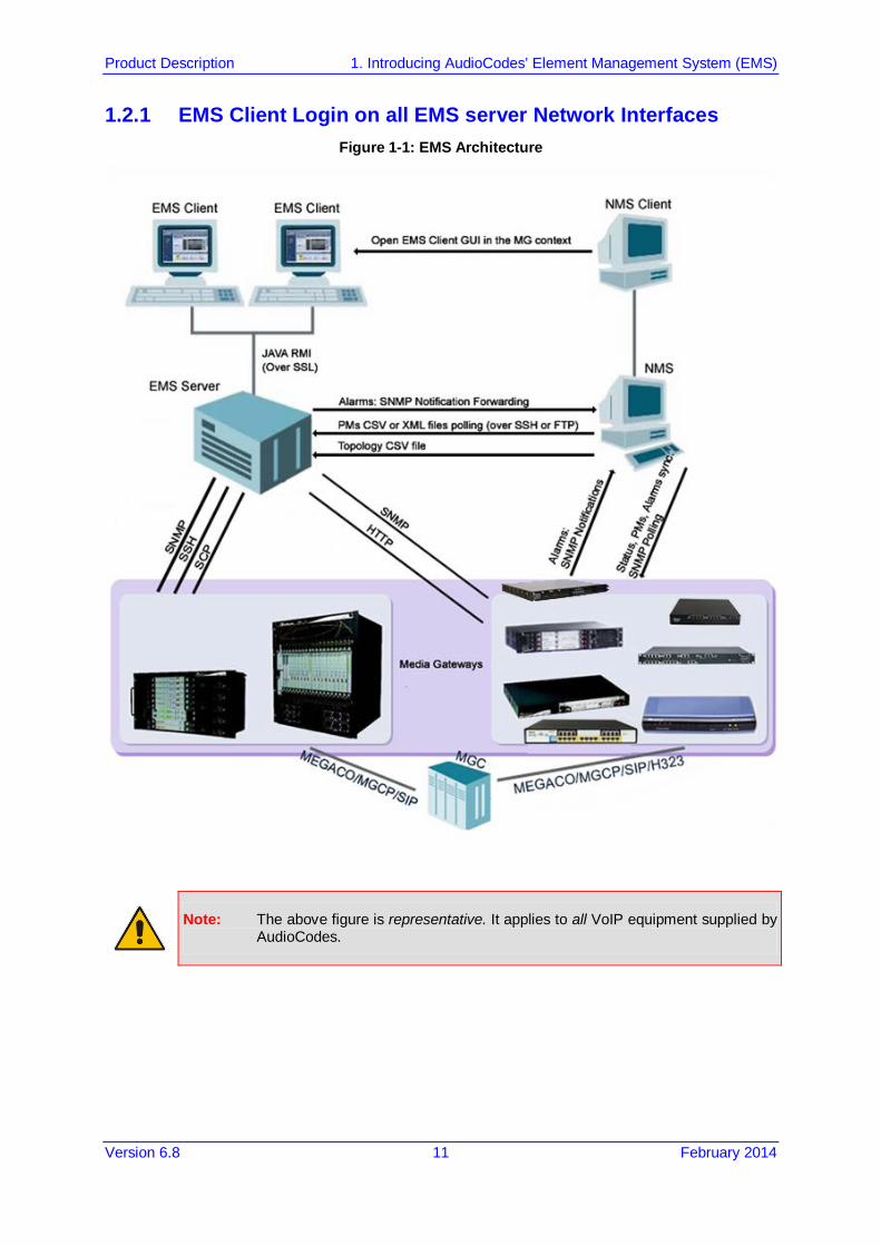
1.2 Architecture Overview The EMS is an open, standard-based, scalable management tool. Typically, the EMS manages the functions and capabilities within each gateway; however does not manage the connectivity between different gateways within the network. To support management of the connectivity between itself and other network elements, the EMS communicates upward to higher-level Network Management Systems (NMSs), according to ITU.T (International Telecommunication Union -Telecommunication Standardization Sector) M3.100 standards on the Telecommunications Management Network (TMN) layered model. This TMN-defined architecture for a layered Operations Support System (OSS) enables service providers to meet customer needs for rapid deployment of new services, as well as meet stringent quality of service (QoS) requirements. Figure 1-1 shows the EMS integrated in a network system.
Product Description 1. Introducing AudioCodes’ Element Management System (EMS)
Version 6.8 11 February 2014
1.2.1 EMS Client Login on all EMS server Network Interfaces Figure 1-1: EMS Architecture
Note: The above figure is representative. It applies to all VoIP equipment supplied by AudioCodes.
EMS and SEM
Product Description 12 Document #: LTRT-94017
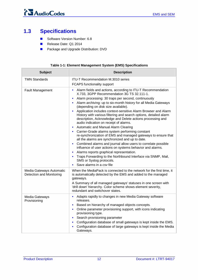
1.3 Specifications Software Version Number: 6.8 Release Date: Q1 2014 Package and Upgrade Distribution: DVD
Table 1-1: Element Management System (EMS) Specifications
Subject Description
TMN Standards ITU-T Recommendation M.3010 series FCAPS functionality support
Fault Management Alarm fields and actions, according to ITU-T Recommendation X.733, 3GPP Recommendation 3G TS 32.111-1.
Alarm processing: 30 traps per second, continuously Alarm archiving: up to six-month history for all Media Gateways
(depending on disk size available). Application includes context-sensitive Alarm Browser and Alarm
History with various filtering and search options, detailed alarm description, Acknowledge and Delete actions processing and audio indication on receipt of alarms.
Automatic and Manual Alarm Clearing Carrier-Grade alarms system performing constant
re-synchronization of EMS and managed gateways to ensure that all the alarms are synchronized and up to date.
Combined alarms and journal allow users to correlate possible influence of user actions on systems behavior and alarms.
Alarms reports graphical representation. Traps Forwarding to the Northbound Interface via SNMP, Mail,
SMS or Syslog protocols. Save alarms in a csv file
Media Gateways Automatic Detection and Monitoring
When the MediaPack is connected to the network for the first time, it is automatically detected by the EMS and added to the managed gateways. A Summary of all managed gateways' statuses in one screen with 'drill down' hierarchy. Color scheme shows element severity, redundant and switchover states.
Media Gateways Provisioning
Adapts rapidly to changes in new Media Gateway software releases.
Based on hierarchy of managed objects concepts. Online parameter provisioning support, with icons indicating
provisioning type. Search provisioning parameter Configuration database of small gateways is kept inside the EMS. Configuration database of large gateways is kept inside the Media
Gateways.

Product Description 1. Introducing AudioCodes’ Element Management System (EMS)
Version 6.8 13 February 2014
Table 1-1: Element Management System (EMS) Specifications
Subject Description
Security Management Complies with T1M1.5/2003-007R4 and covers two aspects: Network communication security and EMS application security. The EMS application complies with the USA Department of Defense standard-FIPS 140-2 (FIPS-Federal Information Processing Standards-US Government Security Standards for Cryptography modules) and the JITC (Joint Interoperability Test Command) lab. Encryption and authentication related software are now implemented using FIPS compliant third party software, Therefore, all encryption modules used by the EMS application are FIPS 140-2 certified. Network Communications Security EMS server's network is configured and its ports opened during installation. Interoperation with firewalls, protecting against unauthorized access by crackers and hackers. MediaPack, Mediant 1000, Mediant 2000, Mediant 3000 can be managed behind the NAT. EMS client-server communication is secured using RMI (Remote Method Invocation) protocol over SSL (Secure Sockets Layer). EMS server - Media Gateway communication is secured using SNMPv2c/SNMPv3, HTTP/HTTPS, Telnet and FTP over IPSec / SSH and SCP. Application Security User Management using a Radius server, TACACS+ or an LDAP (Active Directory) server for centralized user authentication and Authorization or directly in the EMS server database. EMS application: Users List. Authentication-based operator access according to user name, password, PIN, security level, login machine IP. Modification of user details and access rights, user removal, forced logout, user suspension, releasing users from suspension and user password change EMS application: Actions Journal of operators' activities, various filtering and search options.
Performance Management Real-Time Graphics Historical Data Collection and Analysis
EMS and SEM
Product Description 14 Document #: LTRT-94017
Table 1-1: Element Management System (EMS) Specifications
Subject Description
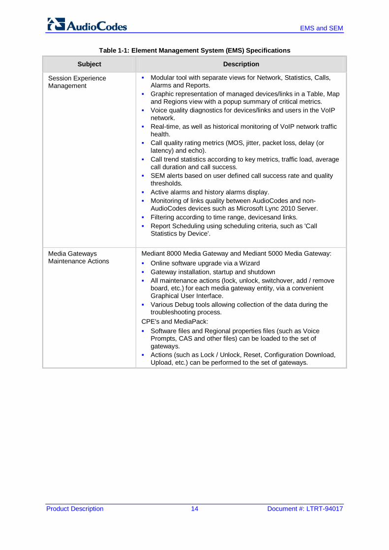
Session Experience Management
Modular tool with separate views for Network, Statistics, Calls, Alarms and Reports.
Graphic representation of managed devices/links in a Table, Map and Regions view with a popup summary of critical metrics.
Voice quality diagnostics for devices/links and users in the VoIP network.
Real-time, as well as historical monitoring of VoIP network traffic health.
Call quality rating metrics (MOS, jitter, packet loss, delay (or latency) and echo).
Call trend statistics according to key metrics, traffic load, average call duration and call success.
SEM alerts based on user defined call success rate and quality thresholds.
Active alarms and history alarms display. Monitoring of links quality between AudioCodes and non-
AudioCodes devices such as Microsoft Lync 2010 Server. Filtering according to time range, devicesand links. Report Scheduling using scheduling criteria, such as 'Call
Statistics by Device'.
Media Gateways Maintenance Actions
Mediant 8000 Media Gateway and Mediant 5000 Media Gateway: Online software upgrade via a Wizard Gateway installation, startup and shutdown All maintenance actions (lock, unlock, switchover, add / remove
board, etc.) for each media gateway entity, via a convenient Graphical User Interface.
Various Debug tools allowing collection of the data during the troubleshooting process.
CPE's and MediaPack: Software files and Regional properties files (such as Voice
Prompts, CAS and other files) can be loaded to the set of gateways.
Actions (such as Lock / Unlock, Reset, Configuration Download, Upload, etc.) can be performed to the set of gateways.
Product Description 1. Introducing AudioCodes’ Element Management System (EMS)
Version 6.8 15 February 2014
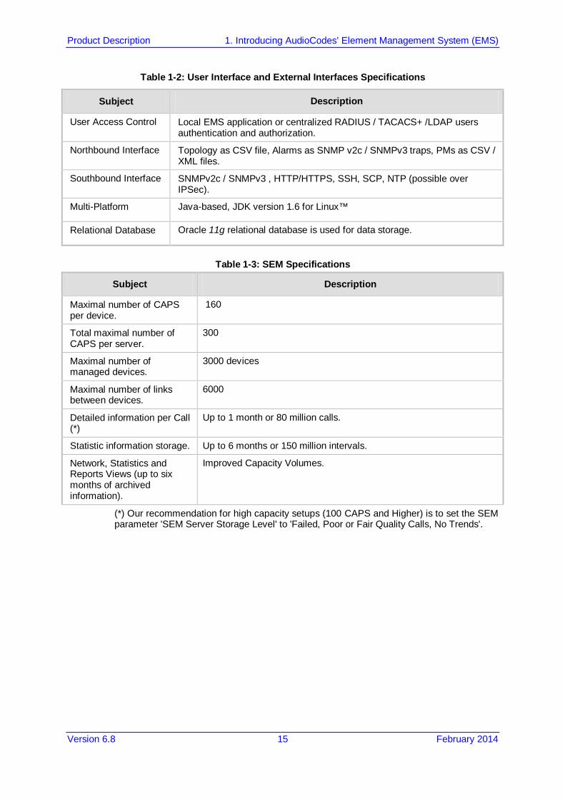
Table 1-2: User Interface and External Interfaces Specifications
Subject Description
User Access Control Local EMS application or centralized RADIUS / TACACS+ /LDAP users authentication and authorization.
Northbound Interface Topology as CSV file, Alarms as SNMP v2c / SNMPv3 traps, PMs as CSV / XML files.
Southbound Interface SNMPv2c / SNMPv3 , HTTP/HTTPS, SSH, SCP, NTP (possible over IPSec).
Multi-Platform Java-based, JDK version 1.6 for Linux™
Relational Database Oracle 11g relational database is used for data storage.
Table 1-3: SEM Specifications
Subject Description
Maximal number of CAPS per device.
160
Total maximal number of CAPS per server.
300
Maximal number of managed devices.
3000 devices
Maximal number of links between devices.
6000
Detailed information per Call (*)
Up to 1 month or 80 million calls.
Statistic information storage. Up to 6 months or 150 million intervals.
Network, Statistics and Reports Views (up to six months of archived information).
Improved Capacity Volumes.
(*) Our recommendation for high capacity setups (100 CAPS and Higher) is to set the SEM parameter 'SEM Server Storage Level' to 'Failed, Poor or Fair Quality Calls, No Trends'.

EMS and SEM
Product Description 16 Document #: LTRT-94017
1.4 Supported VoIP Equipment The table below describes the supported VoIP equipment by the EMS application.
Table 1-4: Supported VoIP Equipment
Supported VoIP Equipment Description
MediaPack
These analog VoIP gateways incorporate up to 24 analog ports to be connected either directly to an enterprise PBX (FXO), to phones, or to fax (FXS), supporting up to 24 simultaneous VoIP calls. (Refer to the product documentation for detailed information.)
Mediant 500 E-SBC
The Mediant 500 Enterprise Session Border Controller (E-SBC), hereafter referred to as the device, is a member of AudioCodes family of E-SBCs, enabling connectivity and security between small medium businesses (SMB) and service providers' VoIP networks. The device provides voice-over-IP (VoIP) SBC functionality. The device offers enhanced dialing plans and voice routing capabilities along with SIP-to-SIP mediation, allowing enterprises to implement SIP Trunking services (IP-to-IP call routing) and IP-based Unified Communications.
Product Description 1. Introducing AudioCodes’ Element Management System (EMS)
Version 6.8 17 February 2014
Table 1-4: Supported VoIP Equipment
Supported VoIP Equipment Description
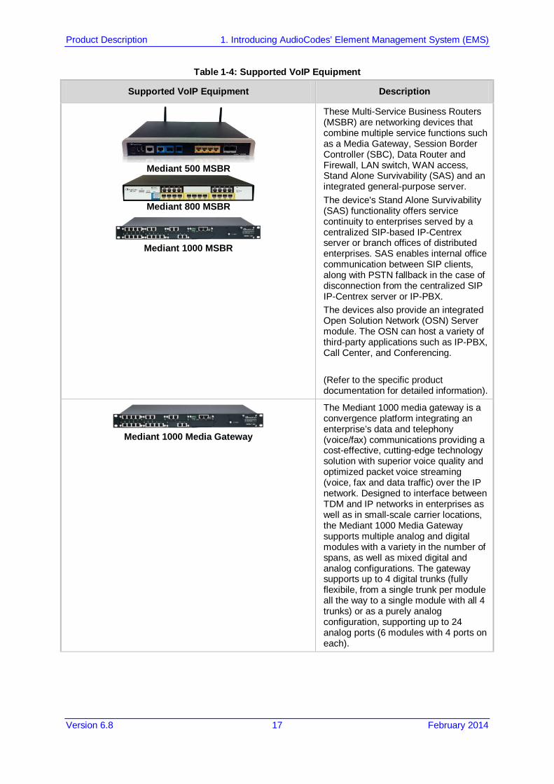
Mediant 500 MSBR
Mediant 800 MSBR
Mediant 1000 MSBR
These Multi-Service Business Routers (MSBR) are networking devices that combine multiple service functions such as a Media Gateway, Session Border Controller (SBC), Data Router and Firewall, LAN switch, WAN access, Stand Alone Survivability (SAS) and an integrated general-purpose server. The device's Stand Alone Survivability (SAS) functionality offers service continuity to enterprises served by a centralized SIP-based IP-Centrex server or branch offices of distributed enterprises. SAS enables internal office communication between SIP clients, along with PSTN fallback in the case of disconnection from the centralized SIP IP-Centrex server or IP-PBX. The devices also provide an integrated Open Solution Network (OSN) Server module. The OSN can host a variety of third-party applications such as IP-PBX, Call Center, and Conferencing. (Refer to the specific product documentation for detailed information).
Mediant 1000 Media Gateway
The Mediant 1000 media gateway is a convergence platform integrating an enterprise’s data and telephony (voice/fax) communications providing a cost-effective, cutting-edge technology solution with superior voice quality and optimized packet voice streaming (voice, fax and data traffic) over the IP network. Designed to interface between TDM and IP networks in enterprises as well as in small-scale carrier locations, the Mediant 1000 Media Gateway supports multiple analog and digital modules with a variety in the number of spans, as well as mixed digital and analog configurations. The gateway supports up to 4 digital trunks (fully flexibile, from a single trunk per module all the way to a single module with all 4 trunks) or as a purely analog configuration, supporting up to 24 analog ports (6 modules with 4 ports on each).

EMS and SEM
Product Description 18 Document #: LTRT-94017
Table 1-4: Supported VoIP Equipment
Supported VoIP Equipment Description
Mediant 600 Media Gateway
The Mediant 600 media gateway supports multiple analog and digital modules with a variety in the number of spans, as well as mixed digital and analog configurations. The gateway supports up to 2 E1/T1/J1 spans (including fractional E1/T1); up to 8 ISDN Basic Rate Interface (BRI) interfaces; up to four FXO interfaces (RJ-11 ports) - for connecting analog lines of an enterprise's PBX or the PSTN to the IP network; up to 4 FXS interfaces (RJ-11 ports) - for connecting legacy telephones, fax machines, and modems to the IP network. Optionally, the FXS interfaces can be connected to the external trunk lines of a PBX. (Refer to the product documentation for detailed information.)
Mediant 2000 Media Gateway
The Mediant 2000 media gateway contains the TP-1610 cPCI VoIP communication board, an ideal building block for deploying high-density, high availability Voice over IP (VoIP) and wireless enterprise systems. The Mediant 2000 incorporates 2, 4, 8 or 16 E1 or T1 spans for connection, either directly to PSTN telephony trunks, or to an enterprise PBX, and two 10/100 Base-T Ethernet ports for redundant connection to the LAN. (Refer to the product documentation for detailed information).
Mediant 500 Enterprise Session Border Controller
(E-SBC)
The Mediant 500 Enterprise Session Border Controller (E-SBC), hereafter referred to as the device, is a member of AudioCodes family of E-SBCs, enabling connectivity and security between small medium businesses (SMB) and service providers' VoIP networks. The device provides voice-over-IP (VoIP) SBC functionality. The device offers enhanced dialing plans and voice routing capabilities along with SIP-to-SIP mediation, allowing enterprises to implement SIP Trunking services (IP-to-IP call routing) and IP-based Unified Communications.
Product Description 1. Introducing AudioCodes’ Element Management System (EMS)
Version 6.8 19 February 2014
Table 1-4: Supported VoIP Equipment
Supported VoIP Equipment Description
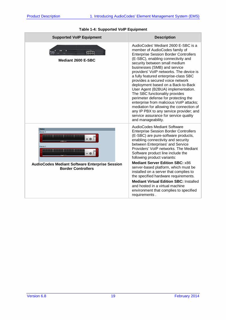
Mediant 2600 E-SBC
AudioCodes' Mediant 2600 E-SBC is a member of AudioCodes family of Enterprise Session Border Controllers (E-SBC), enabling connectivity and security between small medium businesses (SMB) and service providers' VoIP networks. The device is a fully featured enterprise-class SBC provides a secured voice network deployment based on a Back-to-Back User Agent (B2BUA) implementation. The SBC functionality provides perimeter defense for protecting the enterprise from malicious VoIP attacks; mediation for allowing the connection of any IP PBX to any service provider; and service assurance for service quality and manageability.
AudioCodes Mediant Software Enterprise Session
Border Controllers
AudioCodes Mediant Software Enterprise Session Border Controllers (E-SBC) are pure-software products, enabling connectivity and security between Enterprises' and Service Providers’ VoIP networks. The Mediant Software product line include the following product variants: Mediant Server Edition SBC: x86 server-based platform, which must be installed on a server that complies to the specified hardware requirements. Mediant Virtual Edition SBC: Installed and hosted in a virtual machine environment that complies to specified requirements .

EMS and SEM
Product Description 20 Document #: LTRT-94017
Table 1-4: Supported VoIP Equipment
Supported VoIP Equipment Description
Mediant 3000 Media Gateway
The Mediant 3000 media gateway is the medium-sized member of the family of market-ready, standards-compliant, media gateway systems. Main features: Redundant common equipment (Power, Controller, Ethernet Switch); Optional N+1 protection of DSP Cards; Designed for NEBS Level 3; Optimal, cost-effective channel density; Field-proven, high voice quality; SS7/SIGTRAN Interworking (SS7/PRI); Open, scalable architecture; Flexible deployment options; Packet telephony standards-compliant; IETF and ETSI standards-compliant Applications: VoP Trunking gateways, IP-Centrex Gateways, VoP Access gateways Selected specifications: Up to 2,880 independent VoIP to PSTN voice calls; VoiceCoders: include G.711, G.723.1, G.726, G.728, G.729A; G.165 and G.168 compliant echo cancellation; T.38 compliant relay or fall-back to G.711 analog fax and modem support; call progress tones, VAD, CNG, dynamic programmable jitter buffer, modem detection, DTMF detection and generation. Signaling: PSTN: ISDN PRI, CAS, MFC-R2, MF-R1, SS7/M2UA/SIGTRAN Interworking, IP Transport: IETF RFC 1889, RFC 1890 RTP/IP Transport, TCP, UDP (Refer to the product documentation for detailed information).
Mediant 4000 E-SBC
AudioCodes' Mediant 4000 E-SBC is a member of AudioCodes family of Enterprise Session Border Controllers (E-SBC), enabling connectivity and security between small medium businesses (SMB) and service providers' VoIP networks. The device is a fully featured enterprise-class SBC provides a secured voice network deployment based on a Back-to-Back User Agent (B2BUA) implementation. The SBC functionality provides perimeter defense for protecting the enterprise from malicious VoIP attacks; mediation for allowing the connection of any IP PBX to any service provider; and service assurance for service quality and manageability.

Product Description 1. Introducing AudioCodes’ Element Management System (EMS)
Version 6.8 21 February 2014
Table 1-4: Supported VoIP Equipment
Supported VoIP Equipment Description
Mediant 5000 Media Gateway
The Mediant 5000 is the medium-sized member of the family of market-ready, standards-compliant, media gateway systems. Main features: Redundant common equipment (Power, Controller, Ethernet Switch) ; Optional N+1 protection of DSP Cards; Designed for NEBS Level 3; Optimal, cost-effective channel density; Field-proven, high voice quality; SS7/SIGTRAN Interworking (SS7/PRI); Open, scalable architecture; Flexible deployment options; Packet telephony standards-compliant; IETF and ETSI standards-compliant Applications: VoP Trunking Gateways, IP-Centrex Gateways, VoP Access Gateways Selected specifications: Up to 2,880 independent VoIP to PSTN voice calls; VoiceCoders: include G.711, G.723.1, G.726, G.728, G.729A; G.165 and G.168 compliant echo cancellation; T.38 compliant relay or fall-back to G.711 analog fax and modem support; call progress tones, VAD, CNG, dynamic programmable jitter buffer, modem detection, DTMF detection and generation. Signaling: PSTN: ISDN PRI, CAS, MFC-R2, MF-R1, SS7/M2UA/SIGTRAN Interworking, IP Transport: IETF RFC 1889, RFC 1890 RTP/IP Transport, TCP, UDP (Refer to the product documentation for detailed information).
EMS and SEM
Product Description 22 Document #: LTRT-94017
Table 1-4: Supported VoIP Equipment
Supported VoIP Equipment Description
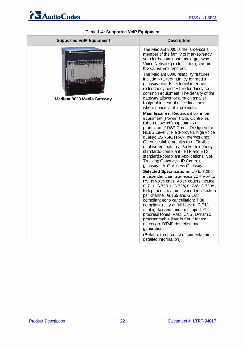
Mediant 8000 Media Gateway
The Mediant 8000 is the large-scale member of the family of market-ready, standards-compliant media gateway Voice Network products designed for the carrier environment. The Mediant 8000 reliability features include N+1 redundancy for media gateway boards, external interface redundancy and 1+1 redundancy for common equipment. The density of the gateway allows for a much smaller footprint in central office locations where space is at a premium. Main features: Redundant common equipment (Power, Fans, Controller, Ethernet switch); Optional N+1 protection of DSP Cards; Designed for NEBS Level 3; Field-proven, high voice quality; SS7/SIGTRAN Interworking; Open, scalable architecture; Flexible deployment options; Packet telephony standards-compliant; IETF and ETSI standards-compliant Applications: VoP Trunking Gateways, IP Centrex gateways, VoP Access Gateways Selected Specifications: Up to 7,200 independent, simultaneous LBR VoP to PSTN voice calls; Voice coders include G.711, G.723.1, G.726, G.728, G.729A, Independent dynamic vocoder selection per channel; G.165 and G.168 compliant echo cancellation; T.38 compliant relay or fall back to G.711 analog, fax and modem support; Call progress tones, VAD, CNG, Dynamic programmable jitter buffer, Modem detection, DTMF detection and generation. (Refer to the product documentation for detailed information).
Product Description 1. Introducing AudioCodes’ Element Management System (EMS)
Version 6.8 23 February 2014
Table 1-4: Supported VoIP Equipment
Supported VoIP Equipment Description
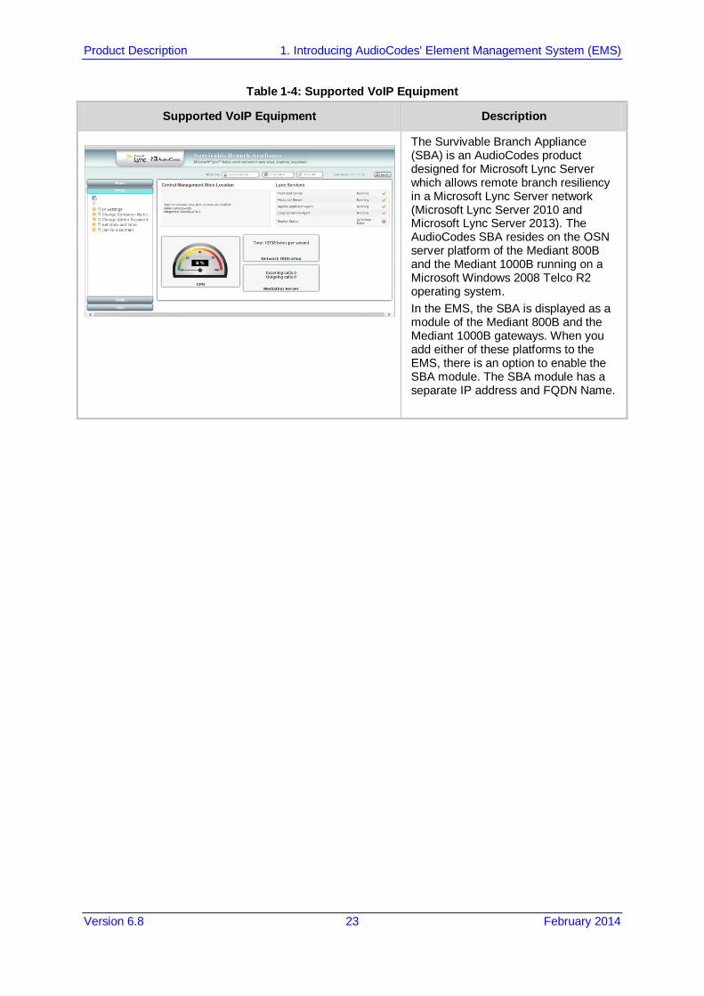
The Survivable Branch Appliance (SBA) is an AudioCodes product designed for Microsoft Lync Server which allows remote branch resiliency in a Microsoft Lync Server network (Microsoft Lync Server 2010 and Microsoft Lync Server 2013). The AudioCodes SBA resides on the OSN server platform of the Mediant 800B and the Mediant 1000B running on a Microsoft Windows 2008 Telco R2 operating system. In the EMS, the SBA is displayed as a module of the Mediant 800B and the Mediant 1000B gateways. When you add either of these platforms to the EMS, there is an option to enable the SBA module. The SBA module has a separate IP address and FQDN Name.

EMS and SEM
Product Description 24 Document #: LTRT-94017
Reader's Notes

Product Description 2. Fault Management
Version 6.8 25 February 2014
2 Fault Management The EMS’s high-level fault management functionality manages and displays all alarms and events from managed elements (received via SNMP traps) and displays them in an Alarm Browser, thereby notifying operators of problems in the system. The EMS’s fault management comprises the Alarm browser and Alarms History.
Figure 2-1: Alarm Browser in EMS Main Screen
2.1 Alarm Processing The EMS can typically process 20 SNMP traps per second continuously. When an alarm is received, it is parsed, stored in the database and immediately displayed in the Alarm browser. The Alarm browser displays current system faults at the top of the alarms list, allowing operators to identify the entity generating the alarm. Operators can pause automatic updating of the displayed alarms to take a system snapshot.

EMS and SEM
Product Description 26 Document #: LTRT-94017
2.2 Alarm Context-Based View The EMS Alarm browser displays alarms and events according to an operator-selected context: Region, Media Gateway or board. This capability (to view the faults of an operator-specified system entity) enables operators to quickly and efficiently isolate and pinpoint a problem’s precise location. In addition to the context-sensitive current alarms view, operators can also view all Journal records and the Alarms History related to the selected context. The EMS can display a combined table with all the alarms, events and journal records to correlate user activities with system behavior and responses. For example, you can filter according to time interval or gateway IP address.
2.3 Graphical Alarm Reports The active and history alarms can be displayed as a set of predefined graphical reports upon a user request. Reports are generated according to the data that is displayed in the Active or History Alarm browser. Graphs include Alarms Severity and Types distribution.
Figure 2-2: Graphical Alarm Reports

Product Description 2. Fault Management
Version 6.8 27 February 2014
2.4 Carrier-Grade Alarms System between the EMS and the Media Gateways The EMS can synchronize with the media gateways on missed alarms which could occur due to network connectivity or other problems. EMS retrieves these missed alarms and adds them to the Alarm browser / History windows. Upon alarms retrieval, depending on the trap forwarding rules, alarms are also forwarded.
2.5 Alarm Priorities According to industry-standard management and communication protocols (ITU-T Recommendation X.733, 3GPP Recommendation 3G TS 32.111-1), the EMS supports 6 prioritized alarm levels (Critical, Major, Minor, Warning, Info and Clear). Each is color-coded so that operators can quickly and easily comprehend severity level and prioritize corrective actions.
2.6 Automatic Alarms and Events Clearing Critical, Major, Minor, Warning or Info alarms are automatically cleared from the Alarms browser (and transferred to Alarms History) by the same entity (source) and the same Media Gateway that originally generated the Critical, Major, Minor, Warning or Info alarms. This feature is available for system debug purposes. Operators view the list of only the currently active alarms. Events are automatically cleared from the Alarm browser after a predefined period of time (default – 3 days). You can easily sort between alarms and events or filter events from the Alarm browser and Alarm History windows.
2.7 Traps Forwarding to the NMS All traps received by the EMS from managed media gateways (both proprietary and standard traps as well as those issued by the EMS application itself) can be forwarded to the NMS (Network Management System. SNMP trap forwarding from the EMS application to a Northbound interface includes the following features: Multiple trap forwarding destinations Media gateway and EMS alarms and events can be forwarded in the following
different types: SNMPv2c or SNMPv3 traps, Mail notifications, Mail to SMS, or Syslog messages.
Each one of the trap destination users can filter trap forwarding according to the following trap types: (Event or Alarm);the source (EMS or Media Gateway);Alarm Severity or Media Gateway IP addresses.
2.8 Save alarms into .csv file Viewed alarms can be saved in a *.csv file from the Alarm browser and Alarms History screens. The alarms in a *.csv file include all alarm fields viewed in the Alarm Details screen. The saved *.csv file can be viewed in Microsoft™ Excel™, enabling all Excel features (statistics, graphs) on it.
EMS and SEM
Product Description 28 Document #: LTRT-94017
2.9 Alarm Types The EMS classifies alarms under five basic types as required by network management standards: Communications Alarm: an alarm of this type is principally associated with the
procedures and/or processes required to convey information from one point to another.
QoS alarm: alarms notifying operators of Quality of Service degradation. Processing Error Alarm: software or processing fault. Equipment Alarm: alarms associated with an equipment fault, such as board or power
supplier failures. Environmental Alarm: alarms such as temperature, power, fire, etc., associated with
the physical environment in which the equipment is located.
2.10 Alarms Actions Operators can perform the following actions regarding the displayed alarms: Acknowledge: informs the other operators that a problem diagnosis is underway. Manual clearing: removes inactive alarms from the operator’s view. Last operator action performed on alarms, including ‘User Name’ and ‘Action Time’
can be viewed in the Alarms History pane.
2.11 Detailed Information Quick access to detailed information on each alarm, including alarm type, probable cause and trap-specific information facilitates diagnosis and troubleshooting. Operators can add free text explaining how to resolve the problem or add information on each alarm displayed in the Alarm browser.
2.12 Active and History Alarm Printing The EMS client can print the EMS alarms details and the Alarms History table.
2.13 Searching and Filtering Options In addition to alarms displayed according to their context (entity) selected, alarms and events can be filtered according to their severity level, acknowledge status, and date and time. In adddition to severity, event, ack state, date and time filters, users can perform a string search in the Alarms History screen.
2.14 Change Alarm Browser View and Level Operators can modify the Alarm browser’s column order according to their preference. In addition, alarms can be sorted by any column (default sorting is according to time). Each user can select the alarms filtering level they wish to apply in their Alarm browser. The following options are supported: Current Level Alarms (default), Node Level Alarms, Region Level Alarms, All Alarms - globe level.
Product Description 2. Fault Management
Version 6.8 29 February 2014
2.15 Audio Indication on Receipt of Alarms Users can choose whether to enable/disable an audio indication (a bell) when new alarms arrive.
2.16 Security The actions that an operator is authorized to perform on alarms depends on the operator’s security level, previously allocated to them by the administrator. Permission to view alarms is separate from permission to respond to alarms. All operator actions, such as alarm acknowledgement and clearing are logged in the EMS’s Actions Journal (see Section 6.3.5 on page 51).
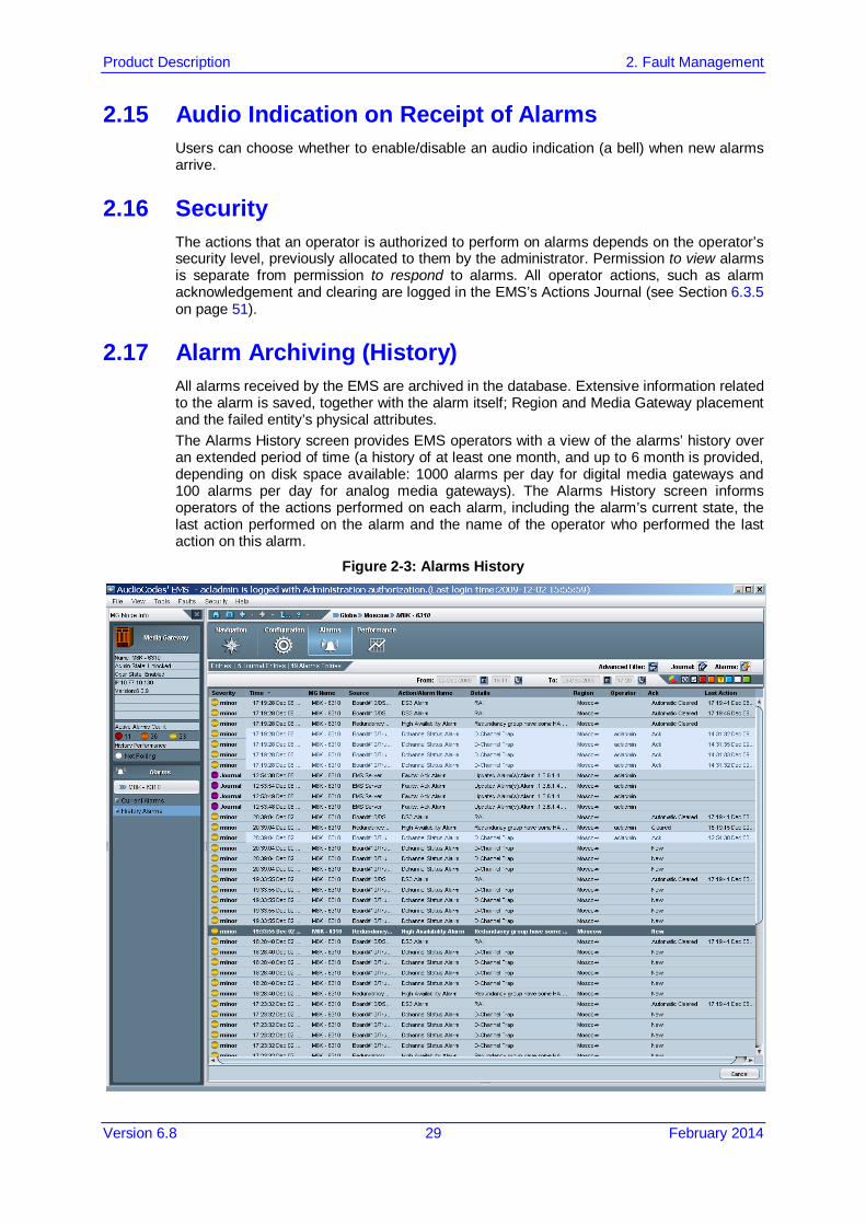
2.17 Alarm Archiving (History) All alarms received by the EMS are archived in the database. Extensive information related to the alarm is saved, together with the alarm itself; Region and Media Gateway placement and the failed entity’s physical attributes. The Alarms History screen provides EMS operators with a view of the alarms’ history over an extended period of time (a history of at least one month, and up to 6 month is provided, depending on disk space available: 1000 alarms per day for digital media gateways and 100 alarms per day for analog media gateways). The Alarms History screen informs operators of the actions performed on each alarm, including the alarm’s current state, the last action performed on the alarm and the name of the operator who performed the last action on this alarm.
Figure 2-3: Alarms History

EMS and SEM
Product Description 30 Document #: LTRT-94017
Reader's Notes

Product Description 3. Session Experience Manager (SEM)
Version 6.8 31 February 2014
3 Session Experience Manager (SEM) The SEM is a valuable new tool that delivers important technical and business statistics, based on AudioCodes methodologies, developed over years of VoIP experience.
Figure 3-1: SEM Map View
The tool enables VoIP network managers to do the following: Rapidly identify the metric or metrics responsible for degradation in the quality of any
VoIP call made over the network. Accurately diagnose and troubleshoot quality problems in response to VoIP user
criticism. Proactively prevent VoIP quality degradation and optimize quality of experience for
VoIP users. The following describes examples of key issues addressed by the SEM module: Identifies overall Voice Quality in the network. Identifies on which device or link ‘Failed’ calls of ‘Poor’ Quality calls were reported. Identifies which metrics caused a deteriation in voice quality. Identifies whether performance deteriorates as the numbers of calls increases. Identifies which users have the most call time. Identifies which metric most affected a specific users call’s quality. Identifies how much bandwidth the network is utilizing. The SEM provides a real-time, as well as historical monitoring and VoIP network health model. Examples of critical call quality metrics that are calculated by the SEM include: the Mean Opinion Score (MOS) Jitter; Delay (or latency); Packet Loss and Echo.

EMS and SEM
Product Description 32 Document #: LTRT-94017
3.1 SEM Data Views The SEM features the following different views: Network:
• Displays a graphic representation of devices in the network in one of the three views: ♦ Map view (the default) – displays a map of devices/links with color coded
status summary. ♦ Table view – displays a list of all the monitored devices (or links) with a
summary of the most important metrics.
• Displays each device’s call quality metrics in a color-coded bar on the device icon • Displays a table matrix for devices and voice metrics. • Displays the distribution of successful / failed calls over a timeline. • Lists the names of the most recently active alarms, each alarm’s Severity level
(color-coded), the Time it was received, and the name of the device triggering it. The Network view can be displayed in three different modes:
Statistics: • Displays Success / Failed calls rate (average success rate (ASR)) of calls over
time; or Average Call Duration, or Failed Calls ratio. • Displays the qualityrating of each call (Good, Fair and Failed) over time and
quality metrics: MOS, Jitter, Delay, Packet Loss and Echo level over time. • Displays the counts and distribution of the Received / Transmitted Octets and
Packets over time. Calls:
The Calls view lists detailed information on each call for both Caller and Callee sides:
• Displays a summary of Call Quality metrics, such as MOS, Jitter and Packet Loss (%), Round Trip Delay (msec) and Echo Level.
• Displays Control Info metrics Source and Destination SIP IP, SIP Port and URIs, as well as the Control Protocol logical entities involved in the call, such as SRD.
• Displays Media Source and Destination SIP IP and Ports. • Displays call trend - Pre-defined linear graphs showing call behavior over time
based on events sent by the VoIP device. • Lists alarms received from the relevant equipment during the specific call. The Calls view includes filters for rapid and focused search such as: Success / Failed calls; Cause: MOS / Jitter / Packet loss / Delay / Echo and the Monitoring Endpoint Type: SBC, IP2IP, FXS, FXO, etc.
The Network and Statistics views graphs includes context links to the Calls view.

Product Description 3. Session Experience Manager (SEM)
Version 6.8 33 February 2014
Reports: The report view allows the user to focus on different aspects of the call analysis:
• Network Status – displays a summary analysis of key call metrics during a specified time period with a separate row entry for each device/link. For example, the ‘Calls Statistics by Device’ report summarizes for selected devices/links, the total percentage of successful and failed calls and metrics such as ‘Number Of Calls’ and ‘Calls Quality’.
• Trends – displays the ‘over time’ behavior (monitored for a specific device/link over specified time intervals) where the same call metrics (described above) are displayed.
• Top Users – includes a list of users sorted according to one of the following metrics: ‘Number Of Calls’; ‘Calls Duration’ and ‘Users Who Experienced Most Poor Quality Calls’ (based on specific metrics).
Reports can be easily customized using filters such as specific devices / links and date/time, columns can be added, users can also generate them based on a specific searched text string and they can be saved in PDF format.
You can automate report generation using scheduling criteria. For example, 'Call Statistics by Device' or 'Call Statistics by Link'. You can set the scheduler to generate hourly, daily, weekly or monthly reports. Set the time of the day to run the report, set the number of times to run the report and forward the report to an email addresses. For example, view a list of generated reports for "Call Utilization by Device".
Alarms: The SEM’s alarms functionality supports both Active Alarms as well as Historical Alarms. Alarms are displayed for calls made on specified devices and time range.
For each of the above views, data can be filtered according to time range, devices, SIP interfaces and links. In addition, SEM can be configured to issue SEM Threshold based alerts, which are also displayed in the Alarms list. Threshold based alerts are an ideal network operator tool for automatic quality analysis. SEM alerts help to avoid false alarms when defining the appropriate minimal number of calls and criteria thresholds. Threshold based alerts are generated as a result of the SEM application data analysis. Alerts are raised and cleared based upon user-defined policies and rules. The alerts are displayed in the ‘Alarms’ view as regular alarms. Rules are provisioned according to criteria, such as specific devices/links, rule frequency and rule time.

EMS and SEM
Product Description 34 Document #: LTRT-94017
Reader's Notes

Product Description 4. Entity Management and Configuration
Version 6.8 35 February 2014
4 Entity Management and Configuration This section describes the Entity Management and Configuration features.
4.1 Automatic Gateway Software Version Detection During the gateway definition in the EMS (Add Gateway action or Auto Detection), EMS connects to the gateway and automatically determines its version (in the case of a new gateway installation).
4.2 Media Gateway Status Summary The EMS enables operators to navigate up and down the entities’ hierarchy from the Navigation pane Regions listed under Globe in the MG Tree expand to display the media gateways under them. These media gateways are also displayed in the MGs List pane. Each is represented by an icon. Each icon is color-coded to enable operators to quickly determine their status and size/shape to enable operators to immediately identify the media gateway type. One glance at the EMS Status pane provides operators with the specified media gateway status and the status of its various components, as well as the overall network status for all gateways managed by the EMS.
Figure 4-1: Mediant 8000 Media Gateway 6310 Status Pane

EMS and SEM
Product Description 36 Document #: LTRT-94017
Figure 4-2: Mediant 5000 Media Gateway 6310 Status Pane
Figure 4-3: Mediant 5000 8410 Status Pane
Figure 4-4: Mediant 3000 Status Pane
Figure 4-5: Mediant 800 MSBG Status Pane
Figure 4-6: Mediant 1000 Status Pane
Product Description 4. Entity Management and Configuration
Version 6.8 37 February 2014
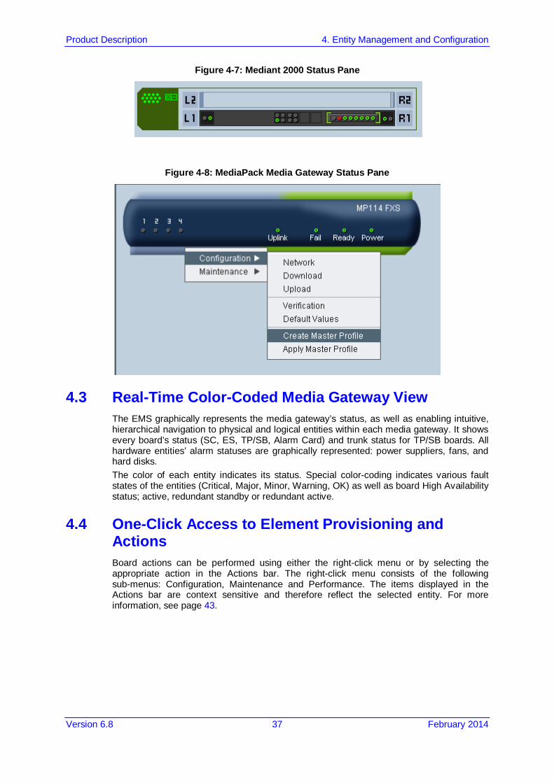
Figure 4-7: Mediant 2000 Status Pane
Figure 4-8: MediaPack Media Gateway Status Pane
4.3 Real-Time Color-Coded Media Gateway View The EMS graphically represents the media gateway’s status, as well as enabling intuitive, hierarchical navigation to physical and logical entities within each media gateway. It shows every board’s status (SC, ES, TP/SB, Alarm Card) and trunk status for TP/SB boards. All hardware entities’ alarm statuses are graphically represented: power suppliers, fans, and hard disks. The color of each entity indicates its status. Special color-coding indicates various fault states of the entities (Critical, Major, Minor, Warning, OK) as well as board High Availability status; active, redundant standby or redundant active.
4.4 One-Click Access to Element Provisioning and Actions Board actions can be performed using either the right-click menu or by selecting the appropriate action in the Actions bar. The right-click menu consists of the following sub-menus: Configuration, Maintenance and Performance. The items displayed in the Actions bar are context sensitive and therefore reflect the selected entity. For more information, see page 43.

EMS and SEM
Product Description 38 Document #: LTRT-94017
4.5 Modular Workflow Process EMS entities are provisioned through an intuitive workflow process consisting of navigation desktops. You can easily navigate between these desktops by clicking on the relevant button in a quick access Toolbar e.g. Configuration.
Figure 4-9: EMS Toolbar
4.5.1 Navigation Desktop When you select a gateway in the MG Tree, the EMS displays the Media Gateway Status screen. A hierarchy tree of provisioning options representing the selected gateway are displayed in the Navigation pane. The options displayed in the hierarchy tree changes according to the selected entity. For example, if you select the Media Gateway board, then all relevant provisioning options for the Media Gateway board are displayed. An MG Tree (displayed in the Navigation pane) enables you to easily view and navigate up/down the provisioning hierarchy tree. For example, Globle > Region > Gateway > Board > Networking. Navigation improvements allow fast transitions between the same status views on different instance indexes. For example, moving from Board #1 to board #3, or from Board #2/Trunk#3 to Board#4/Trunk#7 does not require you to navigate between the boards on the Status screen, and instead can be performed using an index in the Navigation pane. The root navigation level for all the SIP related parameters for the CPE devices is based on the SIP application types i.e, GW and IP to IP, and SBC.
4.5.2 Configuration Desktop Once you have selected the desired provisioning option in the Navigation pane and/or selected an entry in the entity list, you can quickly access the Provisioning screens by clicking the ‘Configuration’ button in the Toolbar. An option to lock/unlock the relevant entity is displayed in the Provisioning screens. At any time, you can return to the Navigation desktop view by clicking the 'Navigation' button in the Toolbar. When provisioning, operators always view in the provisioning screen a location-level indicator (the path of the EMS-managed entity), the Administrative / Operational State (for Mediant 8000) and the Reset State (for other gateways) of the entity being provisioned. Unlock (for Mediant 8000) and Reset (for other gateways) actions to enable the Media Gateway to start operating with the new parameter values can be performed from the provisioning screens. You can keep multiple configuration frames open at the same time and close them one by one, or close all open frames in a single action. In addition, you can close all frames associated with the Media Gateway after it has been removed from the EMS tree.
4.5.3 Alarms Desktop You can display the Alarms browser for the relevant entity by selecting the relevant entity in the Navigation mode and then clicking the ‘Alarms’ button in the Toolbar. In the Alarms pane, you can choose to view either the Current or History Alarms browser. In the Alarms browser Actions bar, you can click the pie-chart to view different graphical statistical representations of the alarms for the selected entity. For more information, see Section 2 on page 25.

Product Description 4. Entity Management and Configuration
Version 6.8 39 February 2014
4.5.4 Performance Desktop You can run Performance Monitoring for the relevant entity by selecting the relevant entity in the Navigation mode, and then clicking the ‘Performance’ button in the Toolbar. In the Performance pane, you can view either History or Real-time performance monitoring. The respective Performance Monitoring provisioning screens are displayed. Starting and Stopping of Polling can be performed from the Main Actions bar or from the Actions bar in the respective Performance Monitoring provisioning screens. For more information, see Section 5 on page 47.
4.5.5 Context-Sensitive Behavior The Status pane as well as the navigation bar allows operators to move up and down the provisioning hierarchy. Operators can always determine their exact location/level in the provisioning hierarchy from the location/level indication at the top of the screen. The Information pane always displays details regarding the current location/level. The entire EMS’s GUI is context-based, affected by any change in location/level: The MG Node Info pane shows details of the selected MOs at the current
location/level MG Tree shows the current region / media gateway, as selected Alarms displayed in the Alarm Browser are contextualized; only alarms associated
with the entity selected in the MG Tree/Status pane/Board are displayed. The Actions bar always reflects the current provisioning location. For example, when
you view the Gateway status screen, you see the most commonly used actions for the Gateway displayed in the Actions bar i.e. Lock, Unlock, Backup, Restore. Alternatively, when a Trunk is selected in the Trunk List at the TP board level, you see the most commonly used actions for the trunk i.e. ‘Lock,’ ‘Unlock’, ‘Activate’, ‘Deactivate’, ‘Create Loopback’ And ‘Remove Loopback’.

EMS and SEM
Product Description 40 Document #: LTRT-94017
4.6 Media Gateway Provisioning This section describes the Media Gateway Provisioning features.
Figure 4-10: Trunk Parameters Provisioning Screen
Provisioning gateway entities is straightforward and operator-friendly via the EMS. Gateway entities such as boards, trunks, call control protocols, etc., are provisioned using the EMS’s Parameters Provisioning screens. Parameter values are loaded to the gateway via SNMP. The Parameter Provisioning screens are easily and intuitively reached by navigating up and down the system hierarchy in the Navigation pane to the entity to be provisioned. When provisioning, operators always view a location-level indicator (the path of the EMS-managed entity), the Administrative / Operational State (for Mediant 5000/Mediant 8000) and the Reset State (for CPE's and MediaPacks) of the entity being provisioned. After provisioning, operators perform the following actions: Unlock (for Mediant 5000/Mediant 8000) and Reset (for CPE's and MediaPacks) to enable the gateway to start operating with the new parameter values. Regional files are loaded in the Software Manager (see Section 4.7.1.1 on page 43).
Product Description 4. Entity Management and Configuration
Version 6.8 41 February 2014
4.6.1 Provisioning Types Three provisioning parameter types are supported in provisioning screens adjacent to modifiable parameters: Instant (changes are applied to the gateway after clicking Apply/OK). Online (the modified entity must be locked prior to applying the changes). Offline/Reset’ (the modified entity must be locked prior to applying the changes and
the physical component (board or Media Gateway) and unlocked (or reset) after applying the changes).These actions can be performed from the Provisioning screen menu. This feature facilitates the parameter provisioning/modifying process for operators.
4.6.2 Provisioning Frame - HA Indication Each provisioning parameter can possibly impact the system’s High Availability configuration. Therefore, an icon in the Provisioning Frame indicates whether changing the parameter’s value impacts HA.
4.6.3 Color - Coding The Parameters List pane in the Parameters Provisioning screens categorizes all provisioning parameters under category tabs. The tabs are color-coded for quick operator assessment. For example, if a parameter is provisioned illegally, the invalid parameter is colored red and a tool tip with the corrective instructions appears. The category tab name is colored red as well. Drop-down combo boxes adjacent to each category tab and to each parameter field in this category, list two actions that operators can optionally perform (for each individual parameter and for each category): “Undo modification/s” and “Factory default value”. A Provisioned parameter tooltip with the parameter range upon mouse click exists for all parameters regardless of their state.
4.6.4 Export / Import / Save Provisioning Data The EMS enables operators to export an entity's entire parameters provisioning screen as a file. This file is in readable XML format. Operators can use this file to import the parameters provisioning screen configuration into another entity of the same type. For example, the parameters provisioning screen configuration of a board can be imported into another board. Alternatively the parameters provisioning screen configuration of a trunk can be imported into another trunk, etc. The entity into which the file is imported can be in another EMS system or in the same EMS system. The EMS also enables operators to export an entity's entire parameters provisioning screen as a printable and easily readable file. This file is in readable txt format.
4.6.5 Parameters Search The context sensitive parameter search option enables you to search for configuration parameters in the gateways provisioning frames. The basic search option enables you to perform a random search for a 'contains' string. Advanced search options enable you to match an exact/any word and to search for a MIB parameter. The configuration frames containing the results parameters can be opened directly after selecting the desired parameter path.
4.6.6 Media Gateway Offline Configuration This feature is relevant for the CPE's and MediaPack products. The media gateway configuration can be performed even if the device is not connected to the network. The EMS saves all configuration changes performed by operators in its database and loads the configuration when ''Configuration Download'' is requested. This feature is used to configure smaller media gateways prior to customer delivery and connection to the network, thereby substantially reducing customer deployment time.

EMS and SEM
Product Description 42 Document #: LTRT-94017
4.6.7 Configuration Upload and Download This feature is relevant for the CPE's and MediaPack products. The configuration of all the devices managed by the EMS application is backed up in the EMS server machine using INI file periodically uploaded from device. The upload is performed automatically and when the user wishes to restore the device configuration, it can be downloaded using the Download Configuration command.
4.6.8 Capability to Save and Restore Gateway Configuration This feature is relevant for the CPE's and MediaPack products. The configurations of the small gateways are saved in the EMS Server. If a gateway is replaced, this capability enables customers to quickly restore the original gateway’s configuration.
4.6.9 Upload INI file from the Gateway The Gateway INI file can be uploaded from the gateway to t from your PC. The INI file is defined as a Debug interface and is used to assist AudioCodes FAEs to perform problem debugging.
4.6.10 Security The EMS’s security management feature enables the operator with the Administrator security level to exert control over other operators’ access to system resources. Thus, sensitive system information cannot be accessed without appropriate authorization, and managed system elements cannot be disrupted by inexpert operators. Security management is performed in the Users List screen and in the Actions Journal screen. The Actions Journal displays all logged user actions, enabling the Administrator to verify appropriate user access to system resources and to provide the Administrator with the means to retroactively analyze actions previously performed by users. See Section 6 on page 51. The EMS supports X.509 Public Key Infrastructure and therefore enables you to generate self-signed certificates, private files and CSR requests.

Product Description 4. Entity Management and Configuration
Version 6.8 43 February 2014
4.7 Media Gateways Maintenance Actions Mediant 5000, Mediant 8000 Maintenance Actions can be performed from either the Actions bar or by right-clicking the relevant entity in the MG Status screen. The Actions bar always reflects the current provisioning location. For example, when you view the Gateway status screen, you see the most commonly used actions for the Gateway displayed in the Actions bar i.e. Lock, Unlock, Backup, Restore. Alternatively, when a Trunk is selected in the Trunk List at the TP board level, you see the most commonly used actions for the trunk i.e. 'Lock', 'Unlock', 'Activate', 'Deactivate', 'Create Loopback' And 'Remove Loopback'.
4.7.1 CPE and Blades Figure 4-11: Maintenance Actions CPE's, MediaPacks)
4.7.1.1 Software Upgrade and Regional Files Distribution EMS operators can load files for a single gateway or for a set of selected gateways. The file loading process is accompanied by an extensive progress report and final loading status indication. Gateway software files and regional properties files (such as Voice Prompts, CAS and other files) can be loaded to the gateway. They’re listed in the Software Manager screen. The Software Manager screen enables operators to view, add or remove configuration and regional files. Each new version, fix or updated file provided to customers is added to the Software Manager.
4.7.1.2 Save Configuration into Flash Memory After completing the gateway configuration process, users can save the configuration and regional files into the gateway’s flash memory. Consequently the gateway will not lose its configuration after Reset.
4.7.1.3 Download INI file to Device You can download an INI file to a device prior to software version download to eliminate the process of validating the INI file with the device's existing configuration (prior to software upgrade). The following options are available for downloading an INI file to a device: Full Configuration INI file download– with validation and apply (recommended). Full Configuration INI file download– without validation and apply (for software
upgrade). Incremental INI file download (previous configuration remains) This action may be
used for replicating configurations to multiple devices of the same type.
EMS and SEM
Product Description 44 Document #: LTRT-94017
4.7.1.4 Configuration Data file Download and Upload Support A configuration file 'Configuration Data' is used to store the data related (router) configuration for the Mediant 800 MSBR and Mediant1000 MSBR devices. This file can be downloaded to these specified devices or uploaded to them by the EMS application.
4.7.1.5 Multiple Gateways Lock / Unlock It’s possible to perform a single and multiple lock/unlock of the gateways from either the MG Status screen or from the MGs Table screen. The locked gateway is color-coded gray in the MGs Tree and Status screen.
4.7.1.6 Resetting a Gateway Users can reset a gateway by selecting the ‘Reset’ option in the Maintenance pop-up menu.
4.7.1.7 Actions on Multiple MGs in one command All the actions described above can be performed on multiple gateways in a single command.
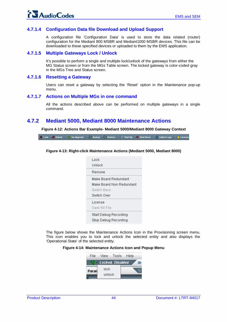
4.7.2 Mediant 5000, Mediant 8000 Maintenance Actions Figure 4-12: Actions Bar Example- Mediant 5000/Mediant 8000 Gateway Context
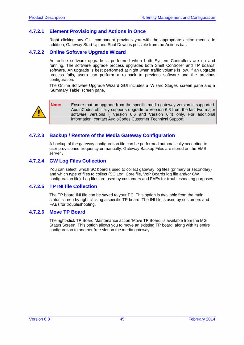
Figure 4-13: Right-click Maintenance Actions (Mediant 5000, Mediant 8000)
The figure below shows the Maintenance Actions Icon in the Provisioning screen menu. This icon enables you to lock and unlock the selected entity and also displays the ‘Operational State’ of the selected entity.
Figure 4-14: Maintenance Actions Icon and Popup Menu
Product Description 4. Entity Management and Configuration
Version 6.8 45 February 2014
4.7.2.1 Element Provisioing and Actions in Once Right clicking any GUI component provides you with the appropriate action menus. In addition, Gateway Start Up and Shut Down is possible from the Actions bar.
4.7.2.2 Online Software Upgrade Wizard An online software upgrade is performed when both System Controllers are up and running. The software upgrade process upgrades both Shelf Controller and TP boards’ software. An upgrade is best performed at night when traffic volume is low. If an upgrade process fails, users can perform a rollback to previous software and the previous configuration. The Online Software Upgrade Wizard GUI includes a ‘Wizard Stages’ screen pane and a ‘Summary Table’ screen pane.
Note: Ensure that an upgrade from the specific media gateway version is supported. AudioCodes officially supports upgrade to Version 6.8 from the last two major software versions ( Version 6.6 and Version 6.4) only. For additional information, contact AudioCodes Customer Technical Support
4.7.2.3 Backup / Restore of the Media Gateway Configuration A backup of the gateway configuration file can be performed automatically according to user provisioned frequency or manually. Gateway Backup Files are stored on the EMS server .
4.7.2.4 GW Log Files Collection You can select which SC boardis used to collect gateway log files (primary or secondary) and which type of files to collect (SC Log, Core file, VoP Boards log file and/or GW configuration file). Log files are used by customers and FAEs for troubleshooting purposes.
4.7.2.5 TP INI file Collection The TP board INI file can be saved to your PC. This option is available from the main status screen by right clicking a specific TP board. The INI file is used by customers and FAEs for troubleshooting.
4.7.2.6 Move TP Board The right-click TP Board Maintenance action 'Move TP Board' is available from the MG Status Screen. This option allows you to move an existing TP board, along with its entire configuration to another free slot on the media gateway.

EMS and SEM
Product Description 46 Document #: LTRT-94017
Reader's Notes

Product Description 5. Performance Management
Version 6.8 47 February 2014
5 Performance Management After service is provisioned for a subscriber under a given QoS level, the service provider must ensure that the purchased level of service is delivered. In the EMS domains s this process involves high-level fault and performance management of the managed entities. The EMS’s Performance Management is composed of real-time and historical data monitoring.
Figure 5-1: Performance Measurement Displays
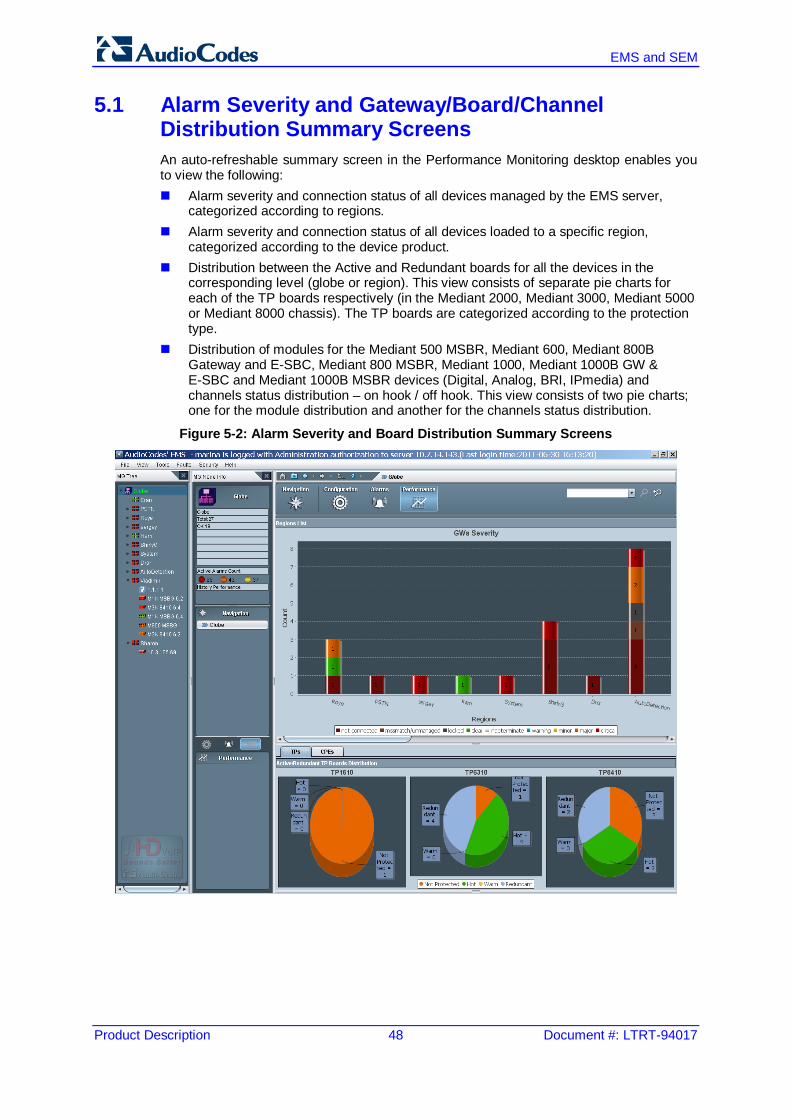
EMS and SEM
Product Description 48 Document #: LTRT-94017
5.1 Alarm Severity and Gateway/Board/Channel Distribution Summary Screens An auto-refreshable summary screen in the Performance Monitoring desktop enables you to view the following: Alarm severity and connection status of all devices managed by the EMS server,
categorized according to regions. Alarm severity and connection status of all devices loaded to a specific region,
categorized according to the device product. Distribution between the Active and Redundant boards for all the devices in the
corresponding level (globe or region). This view consists of separate pie charts for each of the TP boards respectively (in the Mediant 2000, Mediant 3000, Mediant 5000 or Mediant 8000 chassis). The TP boards are categorized according to the protection type.
Distribution of modules for the Mediant 500 MSBR, Mediant 600, Mediant 800B Gateway and E-SBC, Mediant 800 MSBR, Mediant 1000, Mediant 1000B GW & E-SBC and Mediant 1000B MSBR devices (Digital, Analog, BRI, IPmedia) and channels status distribution – on hook / off hook. This view consists of two pie charts; one for the module distribution and another for the channels status distribution.
Figure 5-2: Alarm Severity and Board Distribution Summary Screens

Product Description 5. Performance Management
Version 6.8 49 February 2014
Figure 5-3: Alarm Severity and Gateway/Channel DIstribution
5.2 Real-Time Performance Monitoring – Pre-defined Graphs The Performance Monitoring desktop automatically displays a pre-defined real-time graph showing the progress of key parameters. You can close the pre-defined graph, and/or open and configure additional real-time or history performance monitoring windows. For each one of the managed devices and for each navigation level, the appropriate parameters are selected and displayed to the user.
5.3 Customized Real-Time and History (Background) Graphs The Performance Monitoring desktop enables you to generate customized real-time and history (background) performance monitoring graphs. You can choose from a range of different parameters.

EMS and SEM
Product Description 50 Document #: LTRT-94017
5.3.1 Real-Time Graphs Real-time data monitoring can be used to troubleshoot network or system problems and to isolate a problem after it is detected by the fault management system. In a single graph, users can compare different parameters of the same gateway, or the same parameter over different gateways.
Users can use two graph types to analyze their performance data: table view and line graph. A line graph is generally used when only a few parameters are compared. Table view is used when extensive data is displayed and analyzed.
5.3.2 History (Background) Performance Monitoring Historical data can be used for long-term network analysis and planning. The PM profile, specifying those parameters that users wish to collect from EMS background monitoring can easily be transferred from one gateway to another.
In addition to storing PM background monitoring data in the EMS server database, an xml or csv file can also be created per time interval. The file is created at the end of the PM polling interval in accordance with a user-defined PM profile, and then stored in the EMS server under directory 'Pmfiles'. Users can choose whether to receive a trap when each file is created. The trap contains information as to the file name and the time it was created.
5.4 Aggregated PMs This feature is supported for the Mediant 5000/Mediant 8000 products.
Performance monitoring parameters can be aggregated for all the VoP board statistics. These parameters are defined at the Media Gateway level. For a detailed specification of the parameters list, refer to the Mediant 5000 and Mediant 8000 Alarm and Performance Monitoring Guide.
5.5 Performance Thresholds This feature provides the customer with a powerful and flexible tool for monitoring the healthiness of the system.
Users can define high and low threshold values for History PMs, for both counters and gauge PM types table.
When defined high thresholds are exceeded, an appropriate alarm is issued by the gateway and displayed in the EMS. For example: once ‘Lifetime in Seconds (Max)’ has exceeded the user defined ‘Lifetime High Threshold’, a threshold exceed alarm is generated. The alarm is cleared when the PMs value passes below the defined low threshold value.
The severity of the generated alarm can also be configured by the user.
.
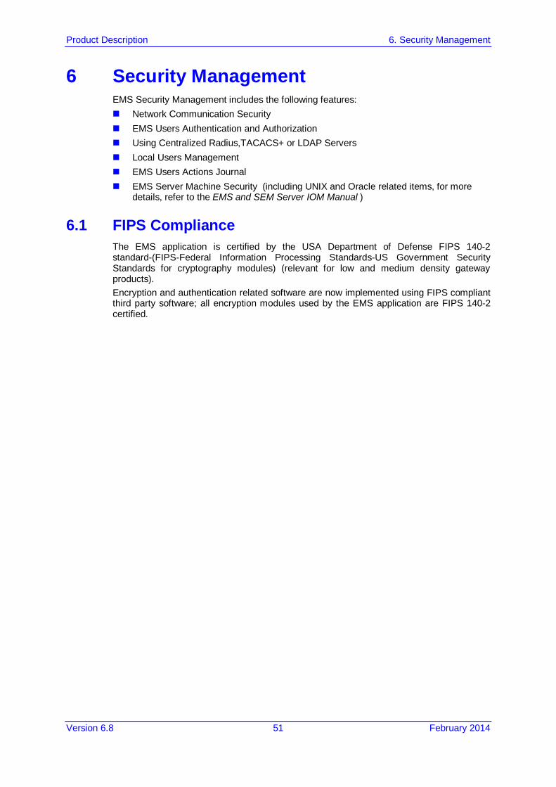
Product Description 6. Security Management
Version 6.8 51 February 2014
6 Security Management EMS Security Management includes the following features: Network Communication Security EMS Users Authentication and Authorization Using Centralized Radius,TACACS+ or LDAP Servers Local Users Management EMS Users Actions Journal EMS Server Machine Security (including UNIX and Oracle related items, for more
details, refer to the EMS and SEM Server IOM Manual )
6.1 FIPS Compliance The EMS application is certified by the USA Department of Defense FIPS 140-2 standard-(FIPS-Federal Information Processing Standards-US Government Security Standards for cryptography modules) (relevant for low and medium density gateway products). Encryption and authentication related software are now implemented using FIPS compliant third party software; all encryption modules used by the EMS application are FIPS 140-2 certified.

EMS and SEM
Product Description 52 Document #: LTRT-94017
6.2 Network Communication Security The figure below shows the EMS firewall configuration schema.
Figure 6-1: Firewall Configuration Schema
The EMS interoperates with firewalls, protecting against unauthorized access by crackers and hackers, thereby securing regular communications. Define rules in your firewall to enable communications between EMS client, server and managed media gateways (refer to the figure above).

Product Description 6. Security Management
Version 6.8 53 February 2014
6.2.1 EMS Client <-> EMS Server The EMS comprises EMS client and server machines, intercommunicating via RMI protocol over TCP. To secure EMS client-server communications, RMI protocol runs over Secure Socket Layer (RMI over SSL).
6.2.2 EMS Server <-> Mediant 5000/Mediant 8000 Media Gateways SNMPv3 or SNMPv2c over IPSec for provisioning, maintenance actions, fault and
performance management. SSH and SCP for installation, software upgrade and auxiliary files management.
6.2.3 EMS Server <-> CPE and MediaPack SNMPv3 or SNMPv2c over IPSec for provisioning, maintenance actions and fault
management. HTTPS for upgrading software and loading regional files.
6.2.4 Media Gateways Access Control All user names and passwords used by the EMS application to access gateways (including SNMP, HTTP and SSH) are stored encrypted in the EMS database.

EMS and SEM
Product Description 54 Document #: LTRT-94017
6.3 EMS Operator Authentication and Authorization Initial access to the EMS application is secured via the Login screen, where access control consists of authentication and authorization with a user name and password. An EMS operator is authenticated and authorized to the EMS application using either the local EMS users management tools or a centralized Radius,TACACS+ or LDAP server. By default, the EMS application manages its users in the local EMS server.
Figure 6-2: EMS Client Login Screen
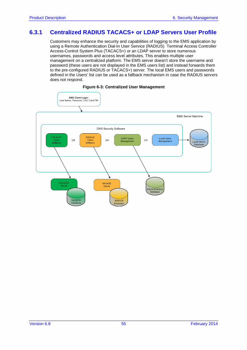
Product Description 6. Security Management
Version 6.8 55 February 2014
6.3.1 Centralized RADIUS TACACS+ or LDAP Servers User Profile Customers may enhance the security and capabilities of logging to the EMS application by using a Remote Authentication Dial-In User Service (RADIUS) Terminal Access Controller Access-Control System Plus (TACACS+) or an LDAP server to store numerous usernames, passwords and access level attributes. This enables multiple user management on a centralized platform. The EMS server doesn’t store the username and password (these users are not displayed in the EMS users list) and instead forwards them to the pre-configured RADIUS or TACACS+) server. The local EMS users and passwords defined in the Users’ list can be used as a fallback mechanism in case the RADIUS servers does not respond.
Figure 6-3: Centralized User Management
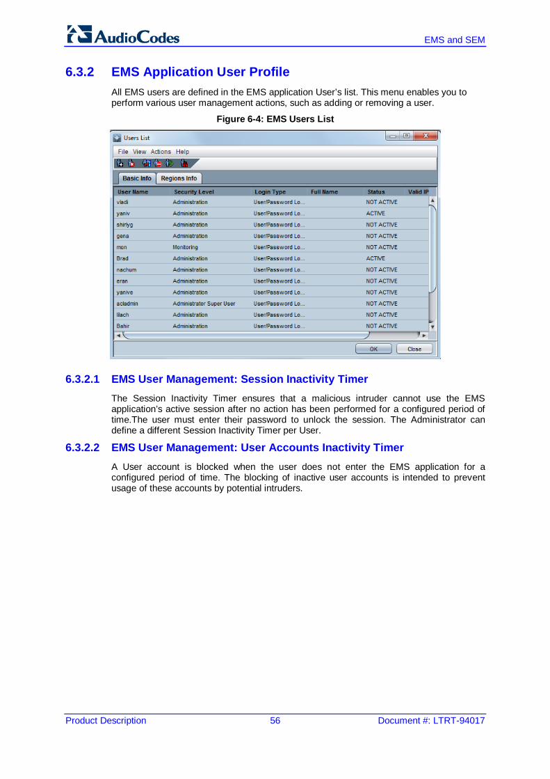
EMS and SEM
Product Description 56 Document #: LTRT-94017
6.3.2 EMS Application User Profile All EMS users are defined in the EMS application User’s list. This menu enables you to perform various user management actions, such as adding or removing a user.
Figure 6-4: EMS Users List
6.3.2.1 EMS User Management: Session Inactivity Timer The Session Inactivity Timer ensures that a malicious intruder cannot use the EMS application’s active session after no action has been performed for a configured period of time.The user must enter their password to unlock the session. The Administrator can define a different Session Inactivity Timer per User.
6.3.2.2 EMS User Management: User Accounts Inactivity Timer A User account is blocked when the user does not enter the EMS application for a configured period of time. The blocking of inactive user accounts is intended to prevent usage of these accounts by potential intruders.

Product Description 6. Security Management
Version 6.8 57 February 2014
6.3.2.3 EMS User Security Levels EMS operators can be allocated one of the following security levels: Monitoring Level (viewing only) (not visible) Operation Level (viewing and all system provisioning operations) (not visible)* Administration Level (viewing, all system provisioning operations, and user security
management). 'Administrator Super User' Level (viewing, all system provisioning operations, and
highest user security management). The user name and security level are displayed in the title bar of the main screen, adjacent to ‘AudioCodes EMS’. When defining users locally, an operator is assigned the administrator security level to exert control over users’ access to system resources so that sensitive system information cannot be accessed without appropriate authorization and that managed system elements cannot be sabotaged. The Administrator can define new users, change user security level, update/modify user details, remove a user from the Users List, perform the forced logout of an active user and/or suspend a user (as well as release an operator from suspension). The status of each user can be viewed in the Users List screen: ACTIVE, NOT ACTIVE, SUSPENDED or AUTOMATICALLY SUSPENDED. The ‘Not Visible’ level allows you to filter views for EMS users with ‘Operator’ and ‘Monitor’ privileges according to sites. For example, an ITSP may have an EMS server installation that can manage multiple clients; where each client is assigned a separate region or alternatively a specific ITSP customer with global operations may wish to secure EMS information confidentially for each corporate region i.e. North West, North East and South.
6.3.3 Multi-Tenancy for Operators The EMS enables you to configure user permissions per region for the EMS application, which is consequently applied to the same adminstrator's privileges in the SEM. In the EMS, each operator can view and configure only those gateways defined in the region upon which they have access privileges. In the SEM, each operator can view/change only those devices and links defined in the region upon which they have access privileges. This includes the entire set of SEM pages: Network, Statistics, Calls, Alarms and Reports.
EMS and SEM
Product Description 58 Document #: LTRT-94017
6.3.3.1 Login Information Display After a successful login to the EMS application, the user is notified with the following information: Latest successful login date, time and EMS client machine IP address. Number of unsuccessful logins since the latest successful login. Latest unsuccessful login date, time and EMS client machine IP address The user can determine whether to enable the last successful login message; lists the
last successful and unsuccessful logon time and date.
6.3.4 Integration with CAC Card The EMS application can use the Common Access Card (CAC) as an alternative method for logging into the EMS client. The Common Access Card (CAC) is a United States Department of Defense (DoD) smart card issued as standard identification for active-duty military personnel, reserve personnel, civilian employees, other non-DoD government employees, state employees of the National Guard and eligible contractor personnel. The EMS application uses data from the CAC card, inserted into the smart card reader on a client PC where the EMS client is run, to perform the following main functions: Authentication (i.e. determines EMS username) Authorization (i.e. determines EMS user privilege level) Encryption (i.e. use the X.509 certificate from the CAC card to establish a TLS
connection between the EMS client and the EMS server). In the EMS login screen, the checkbox 'CAC PIN Number', when selected, displays a field to enter the CAC PIN number to login to the EMS client, instead of entering the EMS username and password. When the user logs in to EMS using the CAC, they are authenticated and authorized using one of the supported methods: EMS server database, TACACS+, Radius or Active Directory databases.

Product Description 6. Security Management
Version 6.8 59 February 2014
6.3.5 Actions Journal The Actions Journal displays all logged user actions, enabling the Administrator to verify appropriate user access to system resources and providing the Administrator with the means to retroactively analyze actions previously performed by users. Every action performed by any user is listed in the Actions Journal with information about the operator, action classification and the exact time the action was taken. The Actions Journal supports the following filters facilitating easy access to required information: User’s Filter, Action Type Filter and the Date and Time Filter.
Figure 6-5: Actions Journal

EMS and SEM
Product Description 60 Document #: LTRT-94017
Reader's Notes

Product Description 7. Virtualized EMS Server
Version 6.8 61 February 2014
7 Virtualized EMS Server The EMS server, in addition to the regular installation, is delivered as a virtual appliance (Hypervisor infra) on the VMware Virtual servers. The virtual environment allows the IT manager, carriers and all EMS customers to minimize dedicated hardware per application usage, and consequently leads to IT maintenance cost savings. On both the VMWare and HyperV servers, EMS can run as Standalone application or as part of a High Availability solution supported by a virtualization vendor. For a list of all supported configurations, refer to the EMS Server IOM Guide.

EMS and SEM
Product Description 62 Document #: LTRT-94017
Reader's Notes

Product Description 8. EMS Server Management
Version 6.8 63 February 2014
8 EMS Server Management 8.1 EMS Server High Availability (HA)
EMS servers High Availability (HA) is supported for EMS server applications running on the Linux platform. Two EMS server machines are required to support High Availability. One machine serving as the Primary machine, and the other serving as the Secondary machine. When the EMS application is active and running, all data stored in the EMS server machine and Database is replicated from the primary machine to the secondary machine. Upon primary machine failure recognition (either on the EMS application or on the network), activity is automatically transferred from the primary server machine to the secondary server machine. Two models of high availability are supported: Regular: both servers are located in the same subnet. A single EMS server IP
address - Global (Virtual) IP address is used for all the network components (EMS clients and managed gateways).
Geographic: each server is located in a different network subnet and has its own IP address. The user provisions both these IP addresses in the client login dialog. The EMS client application constantly searches for the currently active EMS server machine.
8.2 EMS Server File System Security and Maintenance The EMS server Management tool is a command line utility which enables the user to view information on the EMS server and configure its various components. The utility enables you to perform the following tasks: Collect information and logs Perform networking actions, such as changing the EMS server's IP address and
configuring network Interfaces. Perform security actions, such as file integrity checking and configuring SSH. Perform maintenance actions, such as backup, restore and reboot. Configure the EMS HA.
8.2.1 EMS Server File Integrity Checking A File Integrity checker tool periodically verifies whether file attributes were changed (permissions/mode, inode #, number of links, user id, group id, size, access time, modification time, creation/inode modification time). File Integrity violation problems are reported via EMS Security Events. The File Integrity checker tool runs on the EMS server machine.
8.2.2 Disk Array Configuration-RAID-0 on HP ProLiant DL360p Gen8 Servers The HP Array Configuration Utility (ACU) can be used to implement RAID-0 on the EMS server (HP ProLiant DL360p Gen8 machine).
8.2.3 Syslog and Debug Recording Syslog and Debug recordings from all managed machines can be logged directly to the EMS server without the need for a 3rd party server in the same local network.

EMS and SEM
Product Description 64 Document #: LTRT-94017
Reader's Notes
Product Description 9. Northbound Interface
Version 6.8 65 February 2014
9 Northbound Interface EMS supports integration with higher management systems in the following areas: Remote Single Sign-On login from an NMS application to the EMS client via the EMS
CLI. Support for Radius,TACACS+ and LDAP servers for centralized users authentication
and authorization. Fault management (alarms and events forwarding via SNMP protocol). Performance Management (performance monitoring collection enable using XML or
CSV files format). Managed Gateways Topology file using CSV file format. Mediant 5000/Mediant 8000 backup files. EMS server backup files. For more details, refer to the OAMP Integration Guide.
AudioCodes Element Management System (EMS) and Session Experience Manager (SEM)
EMS and SEM
Product Description Version 6.8
www.audiocodes.com


![Quick Guide - audiocodes.com · Cet appareil numérique de la classe [B] ... Analog telephones ... Idle Proxy register failed - Off](https://img.pdfslide.us/doc/110x75/5bdc164d09d3f2bc1c8d36df/quick-guide-cet-appareil-numerique-de-la-classe-b-analog-telephones.jpg)