Embed Size (px)
Citation preview

Manual No: 577013-758 ● Revision: P
Installation Guide
EMR3

Notice
Veeder-Root makes no warranty of any kind with regard to this publication, including, but not limited to, the implied warranties ofmerchantability and fitness for a particular purpose.
Veeder-Root shall not be liable for errors contained herein or for incidental or consequential damages in connection with the furnishing,performance, or use of this publication.
Veeder-Root reserves the right to change system options or features, or the information contained in this publication.
This publication contains proprietary information which is protected by copyright. All rights reserved. No part of this publication may bephotocopied, reproduced, or translated to another language without the prior written consent of Veeder-Root.
Contact TLS Systems Technical Support for additional troubleshooting information at 800-323-1799.
DAMAGE CLAIMS / LOST EQUIPMENT
Thoroughly examine all components and units as soon as they are received. If any cartons are damaged or missing, write a completeand detailed description of the damage or shortage on the face of the freight bill. The carrier's agent must verify the inspection and signthe description. Refuse only the damaged product, not the entire shipment.
Veeder-Root must be notified of any damages and/or shortages within 30 days of receipt of the shipment, as stated in our Terms andConditions.
VEEDER-ROOT’S PREFERRED CARRIER
1. Contact Veeder-Root Customer Service at 800-873-3313 with the specific part numbers and quantities that were missing orreceived damaged.
2. Fax signed Bill of Lading (BOL) to Veeder-Root Customer Service at 800-234-5350.
3. Veeder-Root will file the claim with the carrier and replace the damaged/missing product at no charge to the customer. CustomerService will work with production facility to have the replacement product shipped as soon as possible.
CUSTOMER’S PREFERRED CARRIER
1. It is the customer’s responsibility to file a claim with their carrier.
2. Customer may submit a replacement purchase order. Customer is responsible for all charges and freight associated withreplacement order. Customer Service will work with production facility to have the replacement product shipped as soon aspossible.
3. If “lost” equipment is delivered at a later date and is not needed, Veeder-Root will allow a Return to Stock without a restocking fee.
4. Veeder-Root will NOT be responsible for any compensation when a customer chooses their own carrier.
RETURN SHIPPING
For the parts return procedure, please follow the appropriate instructions in the "General Returned Goods Policy” pages in the"Policies and Literature" section of the Veeder-Root North American Environmental Products price list. Veeder-Root will not acceptany return product without a Return Goods Authorization (RGA) number clearly printed on the outside of the package.
©Veeder-Root 2014. All rights reserved.
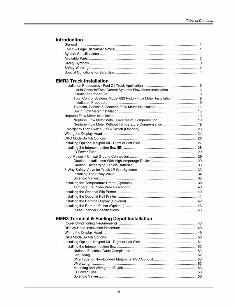
Table of Contents
iii
IntroductionGeneral .............................................................................................................................1EMR3 – Legal Disclaimer Notice ......................................................................................1System Specifications .......................................................................................................1Available Parts ..................................................................................................................2Safety Symbols .................................................................................................................3Safety Warnings ...............................................................................................................4Special Conditions for Safe Use .......................................................................................4
EMR3 Truck InstallationInstallation Procedures - Fuel Oil Truck Application .........................................................6
Liquid Controls/Total Control Systems Flow Meter Installation ................................6Installation Procedure...............................................................................................6Total Control Systems Model 682 Piston Flow Meter Installation ............................9Installation Procedure...............................................................................................9Tokheim, Daniels & Donovan Flow Meter Installation ............................................11Smith Flow Meter Installation .................................................................................15
Neptune Flow Meter Installation .....................................................................................19Neptune Flow Meter With Temperature Compensation .........................................19Neptune Flow Meter Without Temperature Compensation ....................................19
Emergency Stop Switch (ESS) Switch (Optional) ...........................................................23Wiring the Display Head .................................................................................................24C&C Mode Switch Options .............................................................................................26Installing Optional Keypad Kit - Right or Left Side ..........................................................27Installing the Interconnection Box (IB) ............................................................................28
IB Power Fuse ........................................................................................................29Input Power – Critical Ground Connection ......................................................................29
Caution! Installations With High Amperage Devices ..............................................29Caution! Recharging Vehicle Batteries...................................................................30
3-Way Safety Valve for Truck LP Gas Systems .............................................................33Installing The 3-way Valve......................................................................................34Solenoid Valves......................................................................................................35
Installing the Temperature Probe (Optional) ...................................................................38Temperature Probe Wire Description .....................................................................40
Installing the Optional Slip Printer ...................................................................................40Installing the Optional Roll Printer ..................................................................................41Installing the Remote Display (Optional) .........................................................................42Installing the Remote Pulser (Optional) ..........................................................................46
Pulse Encoder Specifications .................................................................................46
EMR3 Terminal & Fueling Depot InstallationPower Conditioning Requirements .................................................................................48Display Head Installation Procedure ...............................................................................48Wiring the Display Head .................................................................................................49C&C Mode Switch Options .............................................................................................50Installing Optional Keypad Kit - Right or Left Side ..........................................................51Installing the Interconnection Box ...................................................................................52
National Electrical Code Compliance .....................................................................52Grounding...............................................................................................................52Wire Type for Non-Bonded Metallic or PVC Conduit..............................................53Wire Length ............................................................................................................53Mounting and Wiring the IB Unit.............................................................................53IB Power Fuse ........................................................................................................53Solenoid Valves......................................................................................................53
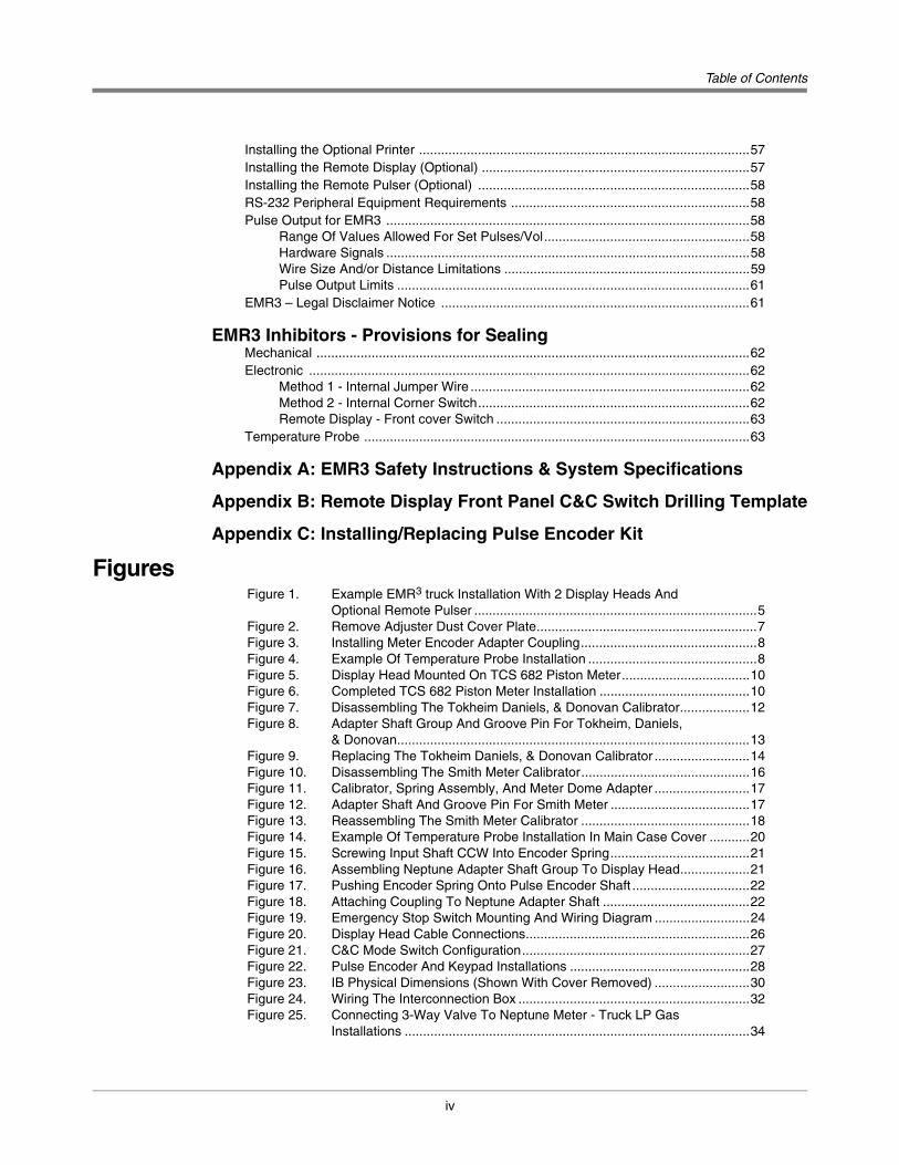
Table of Contents
iv
Installing the Optional Printer ..........................................................................................57Installing the Remote Display (Optional) .........................................................................57Installing the Remote Pulser (Optional) ..........................................................................58RS-232 Peripheral Equipment Requirements .................................................................58Pulse Output for EMR3 ...................................................................................................58
Range Of Values Allowed For Set Pulses/Vol........................................................58Hardware Signals ...................................................................................................58Wire Size And/or Distance Limitations ...................................................................59Pulse Output Limits ................................................................................................61
EMR3 – Legal Disclaimer Notice ....................................................................................61
EMR3 Inhibitors - Provisions for SealingMechanical ......................................................................................................................62Electronic ........................................................................................................................62
Method 1 - Internal Jumper Wire ............................................................................62Method 2 - Internal Corner Switch..........................................................................62Remote Display - Front cover Switch .....................................................................63
Temperature Probe .........................................................................................................63
Appendix A: EMR3 Safety Instructions & System Specifications
Appendix B: Remote Display Front Panel C&C Switch Drilling Template
Appendix C: Installing/Replacing Pulse Encoder Kit
FiguresFigure 1. Example EMR3 truck Installation With 2 Display Heads And
Optional Remote Pulser .............................................................................5Figure 2. Remove Adjuster Dust Cover Plate............................................................7Figure 3. Installing Meter Encoder Adapter Coupling................................................8Figure 4. Example Of Temperature Probe Installation ..............................................8Figure 5. Display Head Mounted On TCS 682 Piston Meter...................................10Figure 6. Completed TCS 682 Piston Meter Installation .........................................10Figure 7. Disassembling The Tokheim Daniels, & Donovan Calibrator...................12Figure 8. Adapter Shaft Group And Groove Pin For Tokheim, Daniels,
& Donovan................................................................................................13Figure 9. Replacing The Tokheim Daniels, & Donovan Calibrator ..........................14Figure 10. Disassembling The Smith Meter Calibrator..............................................16Figure 11. Calibrator, Spring Assembly, And Meter Dome Adapter ..........................17Figure 12. Adapter Shaft And Groove Pin For Smith Meter ......................................17Figure 13. Reassembling The Smith Meter Calibrator ..............................................18Figure 14. Example Of Temperature Probe Installation In Main Case Cover ...........20Figure 15. Screwing Input Shaft CCW Into Encoder Spring......................................21Figure 16. Assembling Neptune Adapter Shaft Group To Display Head...................21Figure 17. Pushing Encoder Spring Onto Pulse Encoder Shaft ................................22Figure 18. Attaching Coupling To Neptune Adapter Shaft ........................................22Figure 19. Emergency Stop Switch Mounting And Wiring Diagram ..........................24Figure 20. Display Head Cable Connections.............................................................26Figure 21. C&C Mode Switch Configuration..............................................................27Figure 22. Pulse Encoder And Keypad Installations .................................................28Figure 23. IB Physical Dimensions (Shown With Cover Removed) ..........................30Figure 24. Wiring The Interconnection Box ...............................................................32Figure 25. Connecting 3-Way Valve To Neptune Meter - Truck LP Gas
Installations ..............................................................................................34

Table of Contents
v
Figure 26. Connecting 3-Way Valve To L.C./TCS Meter - Truck LP Gas Installations ..............................................................................................35
Figure 27. Connecting 3-Way Valve To The IB Box..................................................36Figure 28. Example Wiring Connections For DC And AC Solenoid Valves ..............37Figure 29. Example Thermowell Installation..............................................................38Figure 30. Preparing The Temperature Probe’s Cable For The Protective Cap .......39Figure 31. Positioning The Tie Wrap Over The Temperature Probe’s
Protective Cap..........................................................................................39Figure 32. TM-295 Printer .........................................................................................41Figure 33. U-220A Roll Printer ..................................................................................42Figure 34. Remote Display Assembly .......................................................................44Figure 35. Remote Display Front Cover C&C Switch Installation..............................44Figure 36. Remote Display Connections (Rear Cover Removed).............................45Figure 37. Wiring Connections In Remote Pulser (Top Cover Removed).................46Figure 38. Example Terminal Fueling Depot Installation With 2 Display
Heads And Optional Remote Pulser ........................................................47Figure 39. Digi-Key Power Supply Wiring Diagram...................................................48Figure 40. Display Head Cable Wiring And Switch Locations ...................................50Figure 41. Optional C&C Mode Switch Configuration ...............................................51Figure 42. Optional Pulse Encoder And Keypad Installations ...................................52Figure 43. Terminal IB Wiring....................................................................................55Figure 44. Example Wiring Connections For DC And AC Solenoid Valves ..............56Figure 45. U-220A Roll Printer ..................................................................................57Figure 46. Wiring Pulse Output To A TLS-350 Console............................................59Figure 47. Wiring Pulse Output To A TLS-450 Console............................................60Figure 48. Display Head Sealing ...............................................................................63Figure 49. IB Sealing .................................................................................................64Figure 50. Remote Display Head Sealing .................................................................64Figure C-1. Attach Encoder Mounting Bracket to EMR3 Base..................................C-1Figure C-2. Screwing Input Shaft CCW Into Encoder Spring....................................C-1Figure C-3. Pushing Encoder Spring Onto Pulse Encoder Shaft ..............................C-2Figure C-4. Securing Encoder Input Shaft In EMR3 Base ........................................C-3Figure C-5. Connecting Pulse Encoder Wiring To Display Assembly
Terminal Block........................................................................................C-3
TablesTable 1. Display Head-to-Liquid Controls Adapter Kit 846000-006 .........................6Table 2. V-R Parts Required for Display Head-to-TCS 682 Piston Meter
Installation .................................................................................................9Table 3. Display Head-to-Tokheim, Daniels & Donovan Adapter Kit
846000-004 .............................................................................................11Table 4. Display Head-to-Smith Meter Adapter Kit 846000-005 ...........................15Table 5. Display Head-to-Neptune With Temp. Comp. Adapter Kit
846000-008 .............................................................................................19Table 6. Display Head-to-Neptune W/o Temp. Compensation Adapter Kit
846000-009 .............................................................................................19Table 7. Power Side Wiring for IB Box ..................................................................31Table 8. Intrinsically Safe Wiring for IB .................................................................32Table 9. High-Cab Installation* ..............................................................................40Table 10. Low-Cab Installation* ..............................................................................40Table 11. Remote Display Components ..................................................................42Table 12. Power Side Wiring for IB Box ..................................................................54Table 13. Intrinsically Safe Wiring for IB .................................................................55Table A-1. System Component Dimensions ........................................................... A-3Table A-2. Remote Pulser Dimensions ................................................................... A-3
1
Introduction
General
This manual covers truck and terminal - fueling depot installation of the Veeder-Root Electronic Meter Register (EMR3) System. The EMR3 System consists of several major components:
• Display Head (DH) - The Display Head replaces the mechanical register on a truck or a terminal - fueling depot fuel flow meter. Using the Display Head front panel display and the keys on its face, the operator can choose to dispense either a preset or a variable quantity of product. An optional Temperature Probe is available for temperature compensated product deliveries.
The Display Head must be configured and calibrated before it is placed in service. Once the initial Configuration and Calibration procedures are complete, the Display Head is sealed for weights and measures certification.
• Interconnection Box (IB) - The IB box contains the EMR3 System control circuitry. The IB is mounted in the truck cab or the terminal - fueling depot office. The IB provides an intrinsically-safe barrier for connections to one or two Display Heads located at dispensing points in the hazardous area. IB boxes can accept either 12 or 24 Vdc input power. Note: check label affixed to outside of IB box to verify input power ratings.
• Printer (optional) - A multi-part slip printer (truck cab) or roll printer (terminal - fueling depot office)
• Remote Display (Optional) - For use as a slave Display unit in the cab along with a meter mounted Display Head, or for use as a Display Head (w/ Remote Pulser) in dual meter configurations. Required when used with a meter mounted Remote Pulser.
• Remote Pulser (Optional) - Mounts directly onto meter with cable to Remote Display (required). This pulser is functionally identical to the internal encoder.
EMR3 – Legal Disclaimer Notice
PRODUCT SPECIFICATIONS ARE SUBJECT TO CHANGE WITHOUT NOTICE.
VEEDER-ROOT COMPANY, ITS AFFILIATES AND EMPLOYEES, AND ALL PERSONS ACTING ON ITS OR THEIR OWN BEHALF (COLLECTIVELY) DISCLAIM ANY AND ALL LIABILITY FOR ANY ERRORS, INACCURACIES OR INCOMPLETENESS CONTAINED HEREIN.
VEEDER-ROOT’S EMR3 PRODUCT IS NOT APPROVED FOR USE AS A COMPONENT THAT PROVIDES LIQUID ADDITIVES TO AN AIRCRAFT FUELING SYSTEM WHERE THE ABSENCE OF SUCH ADDITIVES CAN REASONABLY BE EXPECTED TO RESULT IN SIGNIFICANT INJURY TO PERSONS, PROPERTY AND THE ENVIRONMENT. CUSTOMERS USING VEEDER-ROOT PRODUCTS NOT EXPRESSLY INDICATED FOR USE IN SUCH APPLICATIONS DO SO ENTIRELY AT THEIR OWN RISK AND AGREE TO FULLY INDEMNIFY VEEDER-ROOT FOR ANY DAMAGE ARISING OR RESULTING FROM SUCH USE.
THE COMBINATION OF THE EMR3 AND THE PRODUCT METER MUST BE CALIBRATED PRIOR TO PERFORMING CUSTOMER TRANSACTIONS.
System Specifications
• System power: 12 or 24 Vdc, ±20%, fused @ 5 A
• Pulser Capacity: 0 - 1000 Hz
• Temperature compensation range: -45 to +158°F (-50 to +70°C)
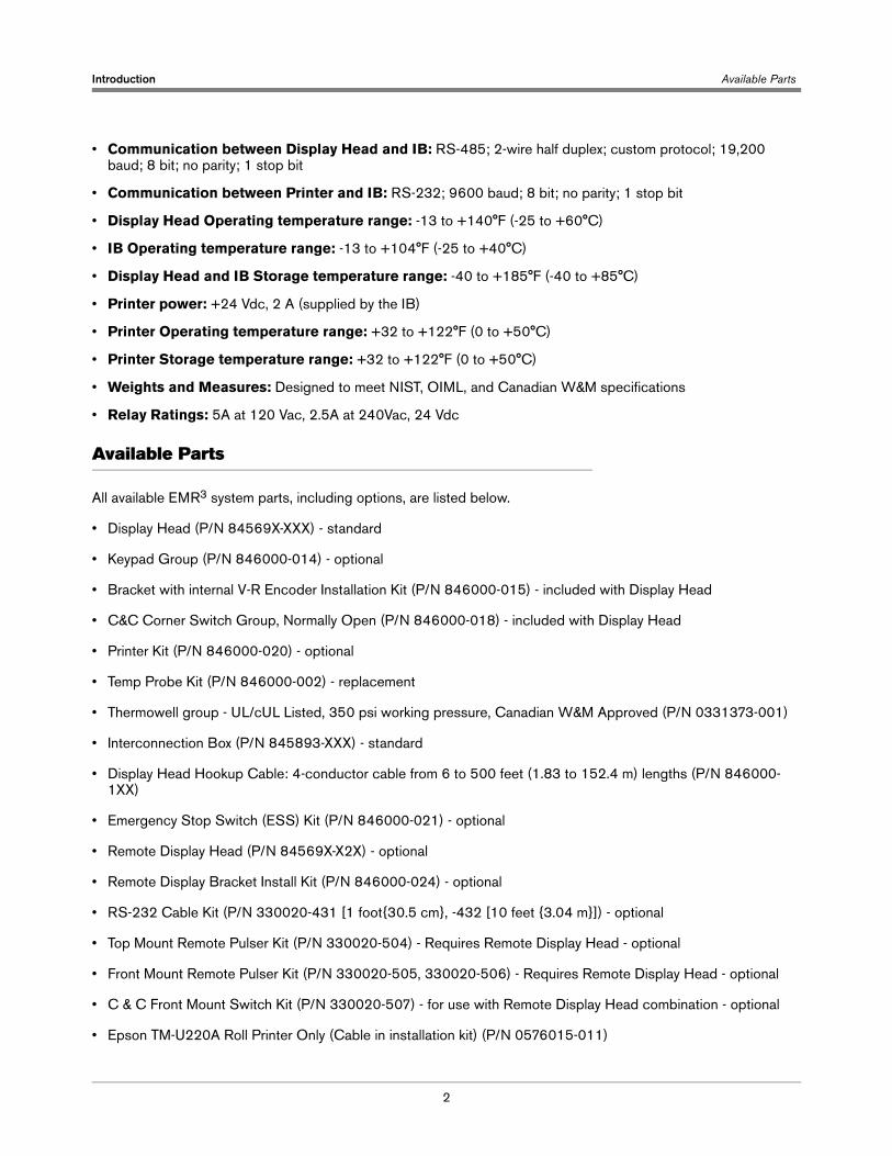
Introduction Available Parts
2
• Communication between Display Head and IB: RS-485; 2-wire half duplex; custom protocol; 19,200 baud; 8 bit; no parity; 1 stop bit
• Communication between Printer and IB: RS-232; 9600 baud; 8 bit; no parity; 1 stop bit
• Display Head Operating temperature range: -13 to +140°F (-25 to +60°C)
• IB Operating temperature range: -13 to +104°F (-25 to +40°C)
• Display Head and IB Storage temperature range: -40 to +185°F (-40 to +85°C)
• Printer power: +24 Vdc, 2 A (supplied by the IB)
• Printer Operating temperature range: +32 to +122°F (0 to +50°C)
• Printer Storage temperature range: +32 to +122°F (0 to +50°C)
• Weights and Measures: Designed to meet NIST, OIML, and Canadian W&M specifications
• Relay Ratings: 5A at 120 Vac, 2.5A at 240Vac, 24 Vdc
Available Parts
All available EMR3 system parts, including options, are listed below.
• Display Head (P/N 84569X-XXX) - standard
• Keypad Group (P/N 846000-014) - optional
• Bracket with internal V-R Encoder Installation Kit (P/N 846000-015) - included with Display Head
• C&C Corner Switch Group, Normally Open (P/N 846000-018) - included with Display Head
• Printer Kit (P/N 846000-020) - optional
• Temp Probe Kit (P/N 846000-002) - replacement
• Thermowell group - UL/cUL Listed, 350 psi working pressure, Canadian W&M Approved (P/N 0331373-001)
• Interconnection Box (P/N 845893-XXX) - standard
• Display Head Hookup Cable: 4-conductor cable from 6 to 500 feet (1.83 to 152.4 m) lengths (P/N 846000-1XX)
• Emergency Stop Switch (ESS) Kit (P/N 846000-021) - optional
• Remote Display Head (P/N 84569X-X2X) - optional
• Remote Display Bracket Install Kit (P/N 846000-024) - optional
• RS-232 Cable Kit (P/N 330020-431 [1 foot{30.5 cm}, -432 [10 feet {3.04 m}]) - optional
• Top Mount Remote Pulser Kit (P/N 330020-504) - Requires Remote Display Head - optional
• Front Mount Remote Pulser Kit (P/N 330020-505, 330020-506) - Requires Remote Display Head - optional
• C & C Front Mount Switch Kit (P/N 330020-507) - for use with Remote Display Head combination - optional
• Epson TM-U220A Roll Printer Only (Cable in installation kit) (P/N 0576015-011)
Introduction Safety Symbols
3
If the EMR3 Display Head will be installed in an application other than replacing a V-R Mechanical Meter Register, you must also have the Veeder-Root approved installation kit for that meter.
The non-temperature compensation kits (200 series), include the necessary meter connection parts, a printer cable, and 35 feet of communications cable for a typical truck application. The temperature compensation kits (300 series), include a temperature probe kit in addition tothe necessary meter connection parts, a printer cable, and 35 feet of communications cable for a typical truck application.
• Kit - installation for Tokheim, Daniels, Energy Flow Systems (Donovan) - Temp Comp (P/N 846000-304)
• Kit - installation for Smith - Temp Comp (P/N 846000-305) Satam, Avery Hardoll, Alfons Haar, Petrol Instruments
• Kit - installation for Liquid Controls, SAMPI, Total Controls Systems - Temp Comp (P/N 846000-306) Tuthill
• Kit - installation for 1-1/2” - 4” Neptune/Liquatech with existing mechanical Temp Comp - Temp Comp (P/N 846000-308)
• Kit - installation for 1-1/2” - 4” Neptune/Liquatech with no existing mechanical Temp Comp - Temp Comp (P/N 846000-309)
• Kit - installation for Brodie Brooks - Temp Comp (P/N 846000-327)
• Kit - Installation for 3/4” and 1” Neptune/Liquatech with existing mechanical Temp Comp (P/N 846000-010)
• Kit - Installation to retrofit 3/4” and 1” Neptune/Liquatech with electronic Temp Comp (P/N 846000-310)
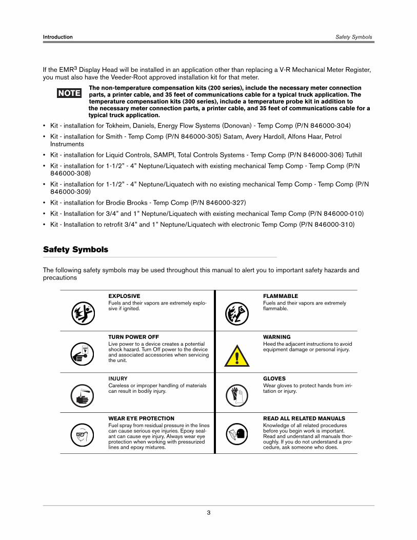
Safety Symbols
The following safety symbols may be used throughout this manual to alert you to important safety hazards and precautions
EXPLOSIVEFuels and their vapors are extremely explo-sive if ignited.
FLAMMABLEFuels and their vapors are extremely flammable.
TURN POWER OFFLive power to a device creates a potential shock hazard. Turn Off power to the device and associated accessories when servicing the unit.
WARNINGHeed the adjacent instructions to avoid equipment damage or personal injury.
INJURYCareless or improper handling of materials can result in bodily injury.
GLOVESWear gloves to protect hands from irri-tation or injury.
WEAR EYE PROTECTIONFuel spray from residual pressure in the lines can cause serious eye injuries. Epoxy seal-ant can cause eye injury. Always wear eye protection when working with pressurized lines and epoxy mixtures.
READ ALL RELATED MANUALSKnowledge of all related procedures before you begin work is important. Read and understand all manuals thor-oughly. If you do not understand a pro-cedure, ask someone who does.
OFF
Introduction Safety Warnings
4
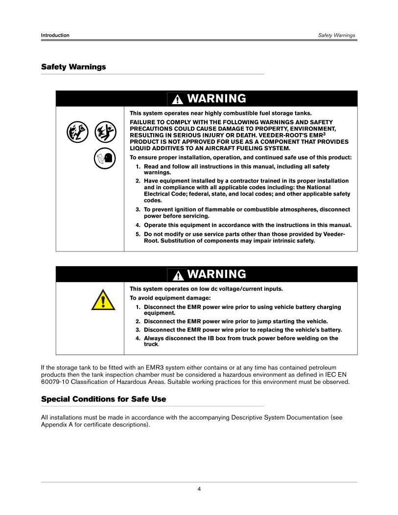
Safety Warnings
If the storage tank to be fitted with an EMR3 system either contains or at any time has contained petroleum products then the tank inspection chamber must be considered a hazardous environment as defined in IEC EN 60079-10 Classification of Hazardous Areas. Suitable working practices for this environment must be observed.
Special Conditions for Safe Use
All installations must be made in accordance with the accompanying Descriptive System Documentation (see Appendix A for certificate descriptions).
WARNINGThis system operates near highly combustible fuel storage tanks.
FAILURE TO COMPLY WITH THE FOLLOWING WARNINGS AND SAFETY PRECAUTIONS COULD CAUSE DAMAGE TO PROPERTY, ENVIRONMENT, RESULTING IN SERIOUS INJURY OR DEATH. VEEDER-ROOT’S EMR3 PRODUCT IS NOT APPROVED FOR USE AS A COMPONENT THAT PROVIDES LIQUID ADDITIVES TO AN AIRCRAFT FUELING SYSTEM.
To ensure proper installation, operation, and continued safe use of this product:
1. Read and follow all instructions in this manual, including all safety warnings.
2. Have equipment installed by a contractor trained in its proper installation and in compliance with all applicable codes including: the National Electrical Code; federal, state, and local codes; and other applicable safety codes.
3. To prevent ignition of flammable or combustible atmospheres, disconnect power before servicing.
4. Operate this equipment in accordance with the instructions in this manual.
5. Do not modify or use service parts other than those provided by Veeder-Root. Substitution of components may impair intrinsic safety.
WARNINGThis system operates on low dc voltage/current inputs.
To avoid equipment damage:
1. Disconnect the EMR power wire prior to using vehicle battery charging equipment.
2. Disconnect the EMR power wire prior to jump starting the vehicle.3. Disconnect the EMR power wire prior to replacing the vehicle's battery.4. Always disconnect the IB box from truck power before welding on the
truck.
5
EMR3 Truck Installation
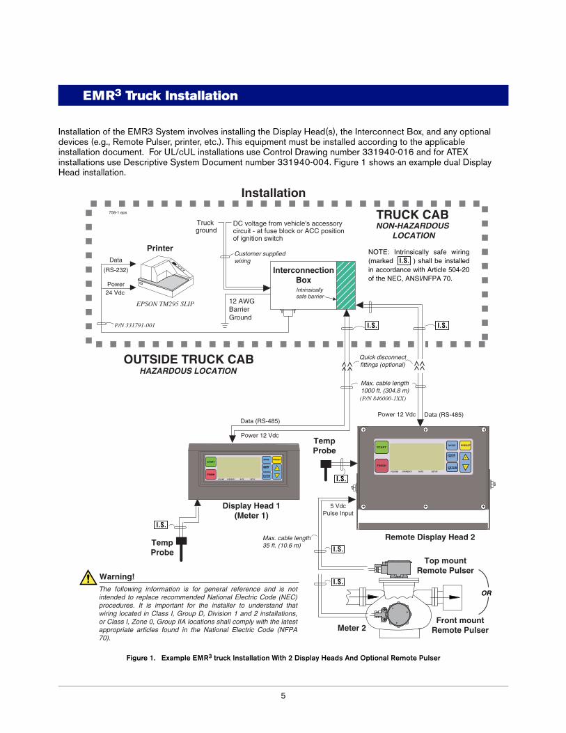
Installation of the EMR3 System involves installing the Display Head(s), the Interconnect Box, and any optional devices (e.g., Remote Pulser, printer, etc.). This equipment must be installed according to the applicable installation document. For UL/cUL installations use Control Drawing number 331940-016 and for ATEX installations use Descriptive System Document number 331940-004. Figure 1 shows an example dual Display Head installation.
Figure 1. Example EMR3 truck Installation With 2 Display Heads And Optional Remote Pulser
DC voltage from vehicle's accessory circuit - at fuse block or ACC position of ignition switch
Display Head 1(Meter 1)
Meter 2
Remote Display Head 2
Top mountRemote Pulser
Front mountRemote Pulser
TRUCK CAB
OUTSIDE TRUCK CAB
Data (RS-485)Data (RS-485)
Power
Data
Power 12 Vdc
Power 12 Vdc
5 VdcPulse Input
NON-HAZARDOUS LOCATION
758-1.eps
(RS-232)
Intrinsicallysafe barrier
Printer
Quick disconnectfittings (optional)
TempProbe
TempProbe
P/N 331791-001
EPSON TM295 SLIP
(P/N 846000-1XX)
Customer supplied wiring
The following information is for general reference and is not intended to replace recommended National Electric Code (NEC) procedures. It is important for the installer to understand that wiring located in Class I, Group D, Division 1 and 2 installations, or Class I, Zone 0, Group IIA locations shall comply with the latest appropriate articles found in the National Electric Code (NFPA 70).
Warning!
24 Vdc
Truck ground
Installation
InterconnectionBox
Max. cable length 35 ft. (10.6 m)
Max. cable length1000 ft. (304.8 m)
12 AWG Barrier Ground
START
FINISH
MODE PRESET
NEXT
ENTER
VOLUME CURRENCY RATE SETUP
HAZARDOUS LOCATION
START
FINISH
MODE PRESET
NEXT
ENTER
VOLUME CURRENCY RATE SETUP
OR
I.S.
I.S.
I.S.
I.S.
I.S.
I.S.
I.S.NOTE: Intrinsically safe wiring (marked ) shall be installed in accordance with Article 504-20 of the NEC, ANSI/NFPA 70.
6
EMR3 - Truck InstallationsEMR3 Truck Installation Installation Procedures - Fuel Oil Truck Application
Installation Procedures - Fuel Oil Truck Application
Follow the installation procedures below for your particular EMR3 approved Flow Meter Installation.
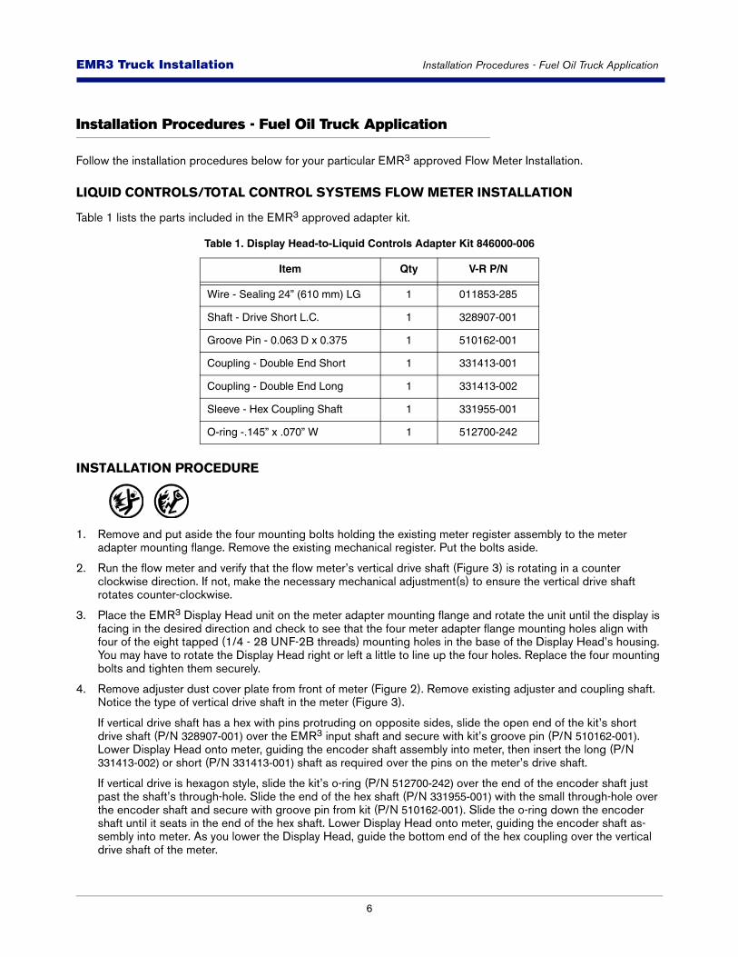
LIQUID CONTROLS/TOTAL CONTROL SYSTEMS FLOW METER INSTALLATION
Table 1 lists the parts included in the EMR3 approved adapter kit.
INSTALLATION PROCEDURE
1. Remove and put aside the four mounting bolts holding the existing meter register assembly to the meter adapter mounting flange. Remove the existing mechanical register. Put the bolts aside.
2. Run the flow meter and verify that the flow meter’s vertical drive shaft (Figure 3) is rotating in a counter clockwise direction. If not, make the necessary mechanical adjustment(s) to ensure the vertical drive shaft rotates counter-clockwise.
3. Place the EMR3 Display Head unit on the meter adapter mounting flange and rotate the unit until the display is facing in the desired direction and check to see that the four meter adapter flange mounting holes align with four of the eight tapped (1/4 - 28 UNF-2B threads) mounting holes in the base of the Display Head’s housing. You may have to rotate the Display Head right or left a little to line up the four holes. Replace the four mounting bolts and tighten them securely.
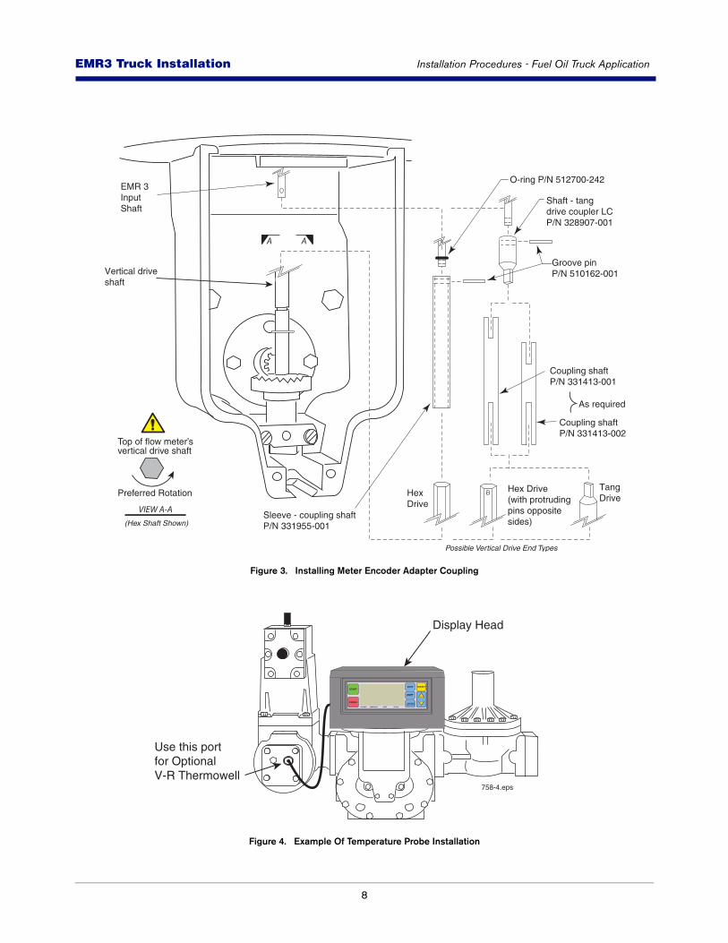
4. Remove adjuster dust cover plate from front of meter (Figure 2). Remove existing adjuster and coupling shaft. Notice the type of vertical drive shaft in the meter (Figure 3).
If vertical drive shaft has a hex with pins protruding on opposite sides, slide the open end of the kit’s short drive shaft (P/N 328907-001) over the EMR3 input shaft and secure with kit’s groove pin (P/N 510162-001). Lower Display Head onto meter, guiding the encoder shaft assembly into meter, then insert the long (P/N 331413-002) or short (P/N 331413-001) shaft as required over the pins on the meter’s drive shaft.
If vertical drive is hexagon style, slide the kit’s o-ring (P/N 512700-242) over the end of the encoder shaft just past the shaft’s through-hole. Slide the end of the hex shaft (P/N 331955-001) with the small through-hole over the encoder shaft and secure with groove pin from kit (P/N 510162-001). Slide the o-ring down the encoder shaft until it seats in the end of the hex shaft. Lower Display Head onto meter, guiding the encoder shaft as-sembly into meter. As you lower the Display Head, guide the bottom end of the hex coupling over the vertical drive shaft of the meter.
Table 1. Display Head-to-Liquid Controls Adapter Kit 846000-006
Item Qty V-R P/N
Wire - Sealing 24” (610 mm) LG 1 011853-285
Shaft - Drive Short L.C. 1 328907-001
Groove Pin - 0.063 D x 0.375 1 510162-001
Coupling - Double End Short 1 331413-001
Coupling - Double End Long 1 331413-002
Sleeve - Hex Coupling Shaft 1 331955-001
O-ring -.145” x .070” W 1 512700-242
7
EMR3 - Truck InstallationsEMR3 Truck Installation Installation Procedures - Fuel Oil Truck Application
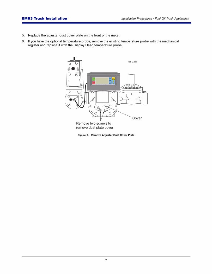
5. Replace the adjuster dust cover plate on the front of the meter.
6. If you have the optional temperature probe, remove the existing temperature probe with the mechanical register and replace it with the Display Head temperature probe.
Figure 2. Remove Adjuster Dust Cover Plate
Remove two screws to remove dust plate cover
758-2.eps
START
FINISH
MODE PRESET
NEXT
ENTER
VOLUME CURRENCY RATE SETUP
Cover
8
EMR3 - Truck InstallationsEMR3 Truck Installation Installation Procedures - Fuel Oil Truck Application
Figure 3. Installing Meter Encoder Adapter Coupling
Figure 4. Example Of Temperature Probe Installation
O-ring P/N 512700-242
Groove pinP/N 510162-001
EMR 3 Input Shaft
Hex Drive(with protrudingpins oppositesides)
Hex Drive
TangDrive
Vertical drive shaft
Shaft - tangdrive coupler LC P/N 328907-001
Coupling shaftP/N 331413-001
Sleeve - coupling shaftP/N 331955-001
Coupling shaftP/N 331413-002
As required
Top of flow meter’svertical drive shaft
Preferred Rotation
(Hex Shaft Shown)
A A
VIEW A-A
Possible Vertical Drive End Types
Use this port for OptionalV-R Thermowell
Display Head
758-4.eps
START
FINISH
MODE PRESET
NEXT
ENTER
VOLUME CURRENCY RATE SETUP
9
EMR3 - Truck InstallationsEMR3 Truck Installation Installation Procedures - Fuel Oil Truck Application
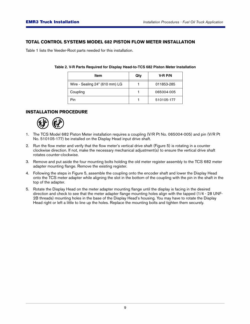
TOTAL CONTROL SYSTEMS MODEL 682 PISTON FLOW METER INSTALLATION
Table 1 lists the Veeder-Root parts needed for this installation.
INSTALLATION PROCEDURE
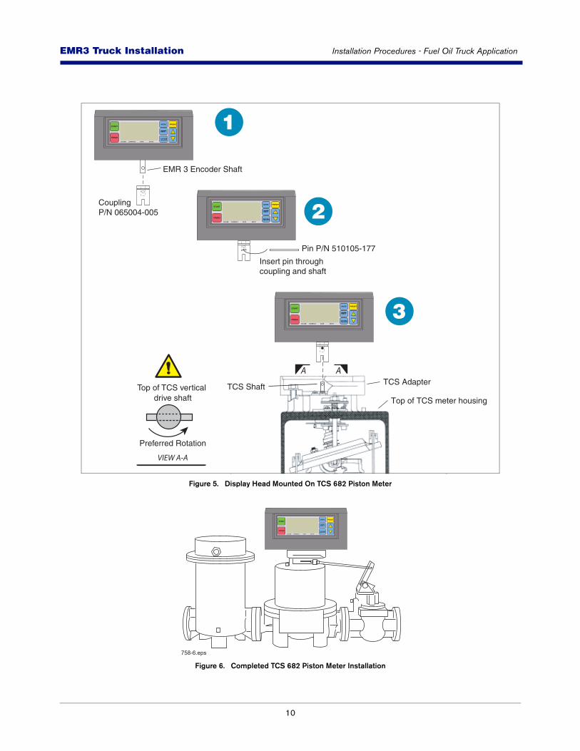
1. The TCS Model 682 Piston Meter installation requires a coupling (V/R Pt No. 065004-005) and pin (V/R Pt No. 510105-177) be installed on the Display Head input drive shaft.
2. Run the flow meter and verify that the flow meter’s vertical drive shaft (Figure 5) is rotating in a counter clockwise direction. If not, make the necessary mechanical adjustment(s) to ensure the vertical drive shaft rotates counter-clockwise.
3. Remove and put aside the four mounting bolts holding the old meter register assembly to the TCS 682 meter adapter mounting flange. Remove the existing register.
4. Following the steps in Figure 5, assemble the coupling onto the encoder shaft and lower the Display Head onto the TCS meter adapter while aligning the slot in the bottom of the coupling with the pin in the shaft in the top of the adapter.
5. Rotate the Display Head on the meter adapter mounting flange until the display is facing in the desired direction and check to see that the meter adapter flange mounting holes align with the tapped (1/4 - 28 UNF-2B threads) mounting holes in the base of the Display Head’s housing. You may have to rotate the Display Head right or left a little to line up the holes. Replace the mounting bolts and tighten them securely.
Table 2. V-R Parts Required for Display Head-to-TCS 682 Piston Meter Installation
Item Qty V-R P/N
Wire - Sealing 24” (610 mm) LG 1 011853-285
Coupling 1 065004-005
Pin 1 510105-177
10
EMR3 - Truck InstallationsEMR3 Truck Installation Installation Procedures - Fuel Oil Truck Application
Figure 5. Display Head Mounted On TCS 682 Piston Meter
Figure 6. Completed TCS 682 Piston Meter Installation
TCS Adapter
EMR 3 Encoder Shaft
TCS Shaft
Top of TCS meter housing
START
FINISH
MODE PRESET
NEXT
ENTER
VOLUME CURRENCY RATE SETUP
Pin P/N 510105-177
Insert pin throughcoupling and shaft
START
FINISH
MODE PRESET
NEXT
ENTER
VOLUME CURRENCY RATE SETUP
START
FINISH
MODE PRESET
NEXT
ENTER
VOLUME CURRENCY RATE SETUP
CouplingP/N 065004-005
1
2
3
Top of TCS vertical drive shaft
Preferred Rotation
A A
VIEW A-A
START
FINISH
MODE PRESET
NEXT
ENTER
VOLUME CURRENCY RATE SETUP
758-6.eps
11
EMR3 - Truck InstallationsEMR3 Truck Installation Installation Procedures - Fuel Oil Truck Application
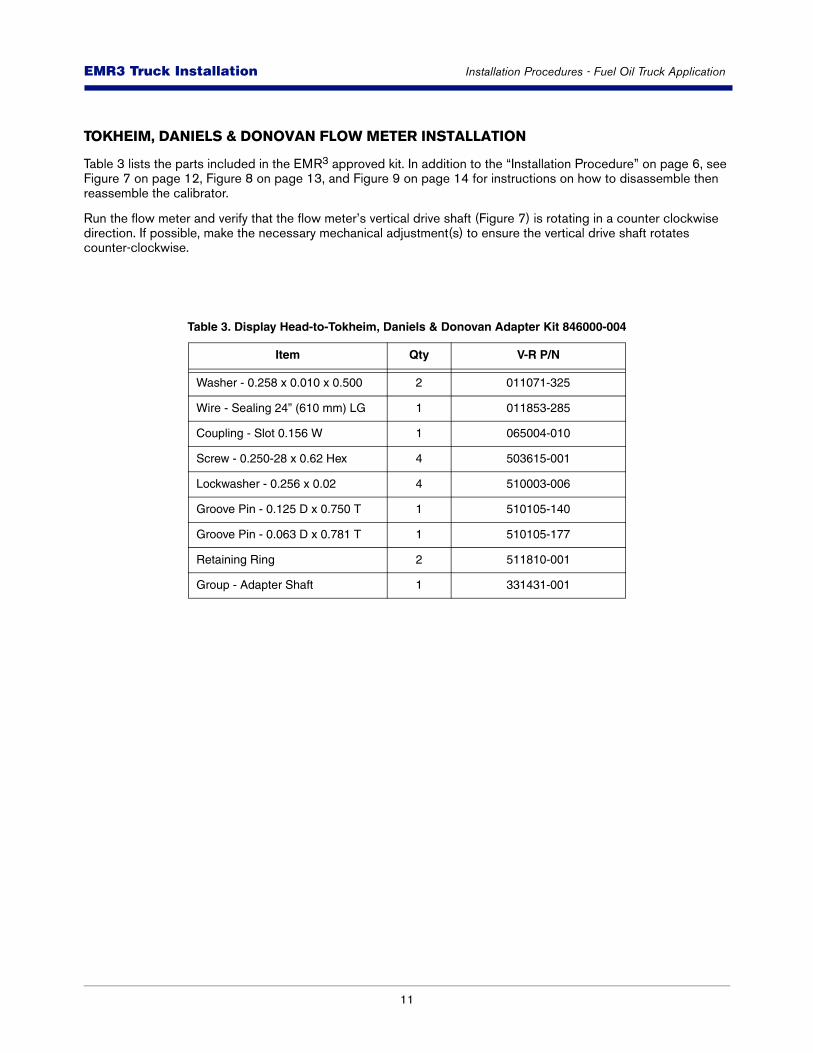
TOKHEIM, DANIELS & DONOVAN FLOW METER INSTALLATION
Table 3 lists the parts included in the EMR3 approved kit. In addition to the “Installation Procedure” on page 6, see Figure 7 on page 12, Figure 8 on page 13, and Figure 9 on page 14 for instructions on how to disassemble then reassemble the calibrator.
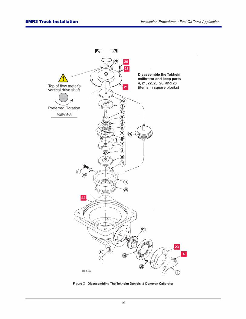
Run the flow meter and verify that the flow meter’s vertical drive shaft (Figure 7) is rotating in a counter clockwise direction. If possible, make the necessary mechanical adjustment(s) to ensure the vertical drive shaft rotates counter-clockwise.
Table 3. Display Head-to-Tokheim, Daniels & Donovan Adapter Kit 846000-004
Item Qty V-R P/N
Washer - 0.258 x 0.010 x 0.500 2 011071-325
Wire - Sealing 24” (610 mm) LG 1 011853-285
Coupling - Slot 0.156 W 1 065004-010
Screw - 0.250-28 x 0.62 Hex 4 503615-001
Lockwasher - 0.256 x 0.02 4 510003-006
Groove Pin - 0.125 D x 0.750 T 1 510105-140
Groove Pin - 0.063 D x 0.781 T 1 510105-177
Retaining Ring 2 511810-001
Group - Adapter Shaft 1 331431-001
12
EMR3 - Truck InstallationsEMR3 Truck Installation Installation Procedures - Fuel Oil Truck Application
Figure 7. Disassembling The Tokheim Daniels, & Donovan Calibrator
22
23
4
28
26
21
Disassemble the Tokheim calibrator and keep parts 4, 21, 22, 23, 26, and 28 (items in square blocks)
758-7.eps
Top of flow meter’svertical drive shaft
Preferred Rotation
A A
VIEW A-A
13
EMR3 - Truck InstallationsEMR3 Truck Installation Installation Procedures - Fuel Oil Truck Application
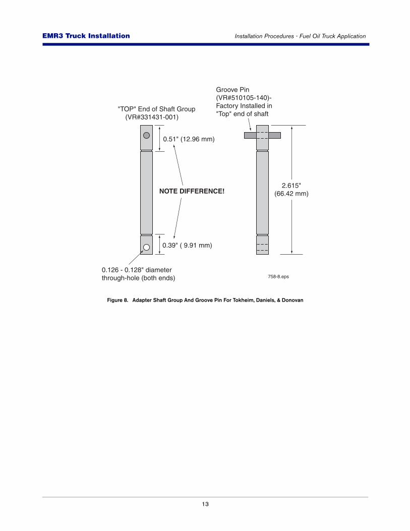
Figure 8. Adapter Shaft Group And Groove Pin For Tokheim, Daniels, & Donovan
0.51" (12.96 mm)
Groove Pin (VR#510105-140)- Factory Installed in "Top" end of shaft
0.39" ( 9.91 mm)
NOTE DIFFERENCE!
"TOP" End of Shaft Group (VR#331431-001)
0.126 - 0.128" diameterthrough-hole (both ends)
2.615"(66.42 mm)
758-8.eps
14
EMR3 - Truck InstallationsEMR3 Truck Installation Installation Procedures - Fuel Oil Truck Application
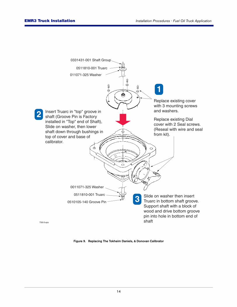
Figure 9. Replacing The Tokheim Daniels, & Donovan Calibrator
0011071-325 Washer
011071-325 Washer
0511810-001 Truarc
0511810-001 Truarc
0510105-140 Groove Pin
Insert Truarc in "top" groove in shaft (Groove Pin is Factory installed in "Top" end of Shaft), Slide on washer, then lower shaft down through bushings in top of cover and base of calibrator.
Replace existing cover with 3 mounting screws and washers.
Replace existing Dial cover with 2 Seal screws.(Reseal with wire and seal from kit).
1
1
2
Slide on washer then insert Truarc in bottom shaft groove. Support shaft with a block ofwood and drive bottom groovepin into hole in bottom end of shaft
3
0331431-001 Shaft Group
758-9.eps
15
EMR3 - Truck InstallationsEMR3 Truck Installation Installation Procedures - Fuel Oil Truck Application
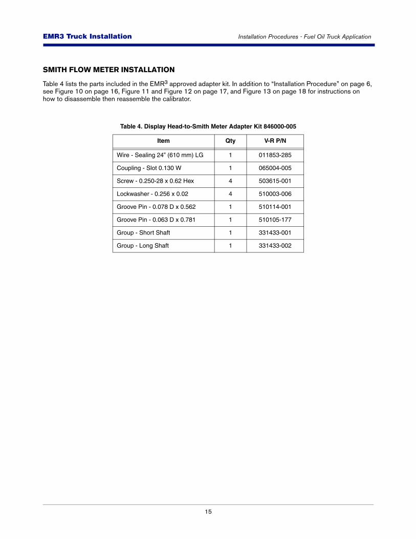
SMITH FLOW METER INSTALLATION
Table 4 lists the parts included in the EMR3 approved adapter kit. In addition to “Installation Procedure” on page 6, see Figure 10 on page 16, Figure 11 and Figure 12 on page 17, and Figure 13 on page 18 for instructions on how to disassemble then reassemble the calibrator.
Table 4. Display Head-to-Smith Meter Adapter Kit 846000-005
Item Qty V-R P/N
Wire - Sealing 24” (610 mm) LG 1 011853-285
Coupling - Slot 0.130 W 1 065004-005
Screw - 0.250-28 x 0.62 Hex 4 503615-001
Lockwasher - 0.256 x 0.02 4 510003-006
Groove Pin - 0.078 D x 0.562 1 510114-001
Groove Pin - 0.063 D x 0.781 1 510105-177
Group - Short Shaft 1 331433-001
Group - Long Shaft 1 331433-002
16
EMR3 - Truck InstallationsEMR3 Truck Installation Installation Procedures - Fuel Oil Truck Application
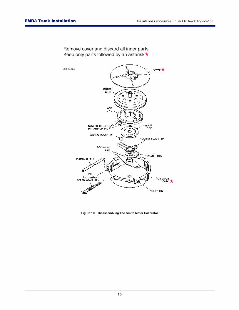
Figure 10. Disassembling The Smith Meter Calibrator
Remove cover and discard all inner parts.Keep only parts followed by an asterisk *
*
*
758-10.eps
17
EMR3 - Truck InstallationsEMR3 Truck Installation Installation Procedures - Fuel Oil Truck Application
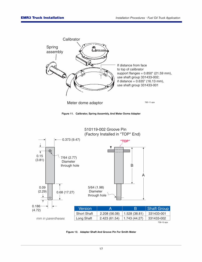
Figure 11. Calibrator, Spring Assembly, And Meter Dome Adapter
Figure 12. Adapter Shaft And Groove Pin For Smith Meter
Calibrator
If distance from faceto top of calibrator support flanges = 0.850" (21.59 mm),use shaft group 331433-002;if distance = 0.635" (16.13 mm), use shaft group 331433-001
Springassembly
Meter dome adaptor 785-11.eps
0.68 (17.27)
0.09(2.29)
0.186(4.72)
0.15(3.81)
B
0.373 (9.47)
Short Shaft 2.208 (56.08) 1.528 (38.81) 331433-001Long Shaft 2.423 (61.54) 1.743 (44.27) 331433-002
A
510119-002 Groove Pin(Factory Installed in "TOP" End)
7/64 (2.77) Diameterthrough hole
5/64 (1.98) Diameterthrough hole
758-12.eps
AVersion Shaft GroupB
"TOP"
mm in parentheses
18
EMR3 - Truck InstallationsEMR3 Truck Installation Installation Procedures - Fuel Oil Truck Application
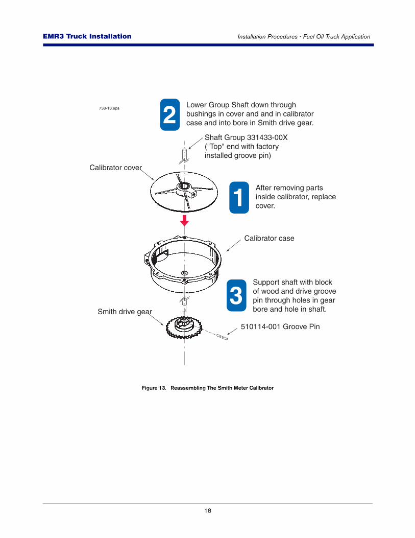
Figure 13. Reassembling The Smith Meter Calibrator
1
2
3510114-001 Groove Pin
Smith drive gear
758-13.eps
Calibrator case
Calibrator cover
Shaft Group 331433-00X("Top" end with factoryinstalled groove pin)
After removing partsinside calibrator, replacecover.
Lower Group Shaft down throughbushings in cover and and in calibratorcase and into bore in Smith drive gear.
Support shaft with blockof wood and drive groovepin through holes in gear bore and hole in shaft.
19
EMR3 - Truck InstallationsEMR3 Truck Installation Neptune Flow Meter Installation
Neptune Flow Meter Installation
Follow the installation procedures for your particular EMR3 approved Flow Meter Installation.
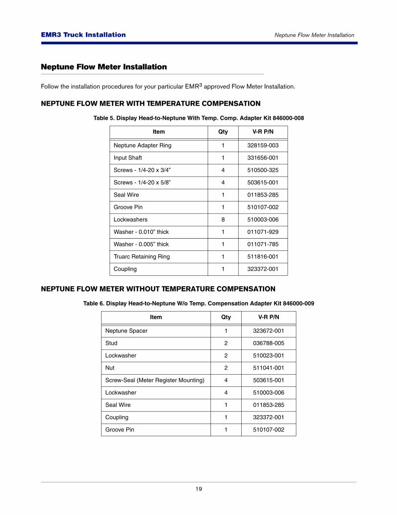
NEPTUNE FLOW METER WITH TEMPERATURE COMPENSATION
NEPTUNE FLOW METER WITHOUT TEMPERATURE COMPENSATION
Table 5. Display Head-to-Neptune With Temp. Comp. Adapter Kit 846000-008
Item Qty V-R P/N
Neptune Adapter Ring 1 328159-003
Input Shaft 1 331656-001
Screws - 1/4-20 x 3/4” 4 510500-325
Screws - 1/4-20 x 5/8” 4 503615-001
Seal Wire 1 011853-285
Groove Pin 1 510107-002
Lockwashers 8 510003-006
Washer - 0.010” thick 1 011071-929
Washer - 0.005” thick 1 011071-785
Truarc Retaining Ring 1 511816-001
Coupling 1 323372-001
Table 6. Display Head-to-Neptune W/o Temp. Compensation Adapter Kit 846000-009
Item Qty V-R P/N
Neptune Spacer 1 323672-001
Stud 2 036788-005
Lockwasher 2 510023-001
Nut 2 511041-001
Screw-Seal (Meter Register Mounting) 4 503615-001
Lockwasher 4 510003-006
Seal Wire 1 011853-285
Coupling 1 323372-001
Groove Pin 1 510107-002
20
EMR3 - Truck InstallationsEMR3 Truck Installation Neptune Flow Meter Installation
1. Remove and put aside the four mounting bolts holding the meter register assembly to the meter adapter mounting flange. Remove the existing mechanical register.
2. Remove the cover, P/N 86665-000, from the mechanical register’s lever arm assembly.
3. Remove the lever arm assembly from the meter. Keep the locking pin (P/N 86661-001).
4. Remove and put aside the four mounting bolts holding the meter register assembly to the spacer (these bolts may be needed for reassembly).
5. Remove the mechanical meter register and the (4) temperature compensator bolts. Take out the compensator gear assembly.
6. Keep the main case cover (P/N 400081-002) and the spacer (P/N 86711-000) in place. Clean off the top of the spacer.
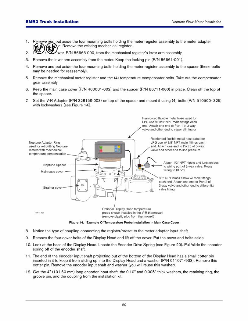
7. Set the V-R Adapter (P/N 328159-003) on top of the spacer and mount it using (4) bolts (P/N 510500- 325) with lockwashers [see Figure 14].
Figure 14. Example Of Temperature Probe Installation In Main Case Cover
8. Notice the type of coupling connecting the register/preset to the meter adapter input shaft.
9. Remove the four cover bolts of the Display Head and lift off the cover. Put the cover and bolts aside.
10. Look at the base of the Display Head. Locate the Encoder Drive Spring (see Figure 20). Pull/slide the encoder spring off of the encoder shaft.
11. The end of the encoder input shaft projecting out of the bottom of the Display Head has a small cotter pin inserted in it to keep it from sliding up into the Display Head and a washer (P/N 011071-933). Remove this cotter pin. Remove the encoder input shaft and washer (you will reuse this washer).
12. Get the 4” (101.60 mm) long encoder input shaft, the 0.10” and 0.005” thick washers, the retaining ring, the groove pin, and the coupling from the installation kit.
Strainer cover
Neptune Adapter Ringused for retrofitting Neptune meters with mechanical temperature compensation
Optional Display Head temperature probe shown installed in the V-R thermowell (remove plastic plug from thermowell)
Main case cover
Neptune Spacer
758-14.eps
Reinforced flexible metal hose rated for LPG use w/ 3/8" NPT male fittings each end. Attach one end to Port 1 of 3-way valve and other end to vapor eliminator
Reinforced flexible metal hose rated for LPG use w/ 3/8" NPT male fittings each end. Attach one end to Port 3 of 3-way valve and other end to line pressure
3/8" NPT brass elbow w/ male fittings each end. Attach one end to Port 2 of 3-way valve and other end to differentialvalve fitting.
Attach 1/2" NPT nipple and junction boxto wiring port of 3-way valve. Routewiring to IB box
START
FINISH
MODE PRESET
NEXT
ENTER
VOLUME CURRENCY RATE SETUP
21
EMR3 - Truck InstallationsEMR3 Truck Installation Neptune Flow Meter Installation
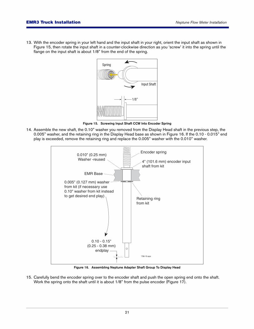
13. With the encoder spring in your left hand and the input shaft in your right, orient the input shaft as shown in Figure 15, then rotate the input shaft in a counter-clockwise direction as you ‘screw’ it into the spring until the flange on the input shaft is about 1/8” from the end of the spring.
Figure 15. Screwing Input Shaft CCW Into Encoder Spring
14. Assemble the new shaft, the 0.10” washer you removed from the Display Head shaft in the previous step, the 0.005” washer, and the retaining ring in the Display Head base as shown in Figure 16. If the 0.10 - 0.015” end play is exceeded, remove the retaining ring and replace the 0.005” washer with the 0.010” washer.
Figure 16. Assembling Neptune Adapter Shaft Group To Display Head
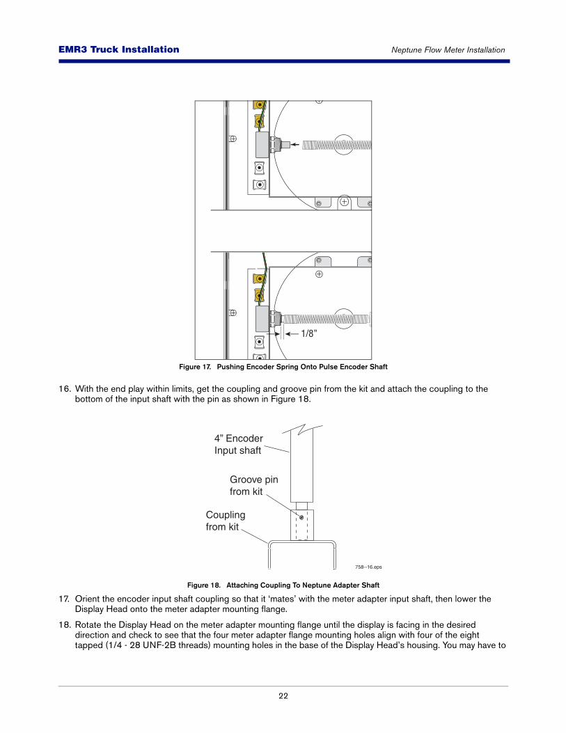
15. Carefully bend the encoder spring over to the encoder shaft and push the open spring end onto the shaft. Work the spring onto the shaft until it is about 1/8” from the pulse encoder (Figure 17).
Input Shaft
Spring
1/8”
EMR Base
Encoder spring0.010" (0.25 mm) Washer -reused
0.005" (0.127 mm) washer from kit (if necessary use 0.10" washer from kit insteadto get desired end play)
Retaining ringfrom kit
0.10 - 0.15"
(0.25 - 0.38 mm) endplay
4" (101.6 mm) encoder inputshaft from kit
758-15.eps
22
EMR3 - Truck InstallationsEMR3 Truck Installation Neptune Flow Meter Installation
Figure 17. Pushing Encoder Spring Onto Pulse Encoder Shaft
16. With the end play within limits, get the coupling and groove pin from the kit and attach the coupling to the bottom of the input shaft with the pin as shown in Figure 18.
Figure 18. Attaching Coupling To Neptune Adapter Shaft
17. Orient the encoder input shaft coupling so that it ‘mates’ with the meter adapter input shaft, then lower the Display Head onto the meter adapter mounting flange.
18. Rotate the Display Head on the meter adapter mounting flange until the display is facing in the desired direction and check to see that the four meter adapter flange mounting holes align with four of the eight tapped (1/4 - 28 UNF-2B threads) mounting holes in the base of the Display Head’s housing. You may have to
1/8”
Groove pinfrom kit
4” EncoderInput shaft
Couplingfrom kit
758--16.eps

23
EMR3 - Truck InstallationsEMR3 Truck Installation Emergency Stop Switch (ESS) Switch (Optional)
rotate the Display Head right or left a little to line up four holes. Use (4) hex bolts with the seal wire hole in the bolt head (P/N 503615-001) to mount the Display Head to the adapter.
19. If a mechanical (or other) temperature compensator is being replaced, remove the temperature sensing element from the thermowell.
Remove or disable the mechanical compensator. The EMR3 will not work with mechani-cal temperature compensation and trying to do so will result in inaccurate deliveries.
20. Reference section of the EMR3 Setup and Operation manual for Temperature Probe Verification.
Emergency Stop Switch (ESS) Switch (Optional)
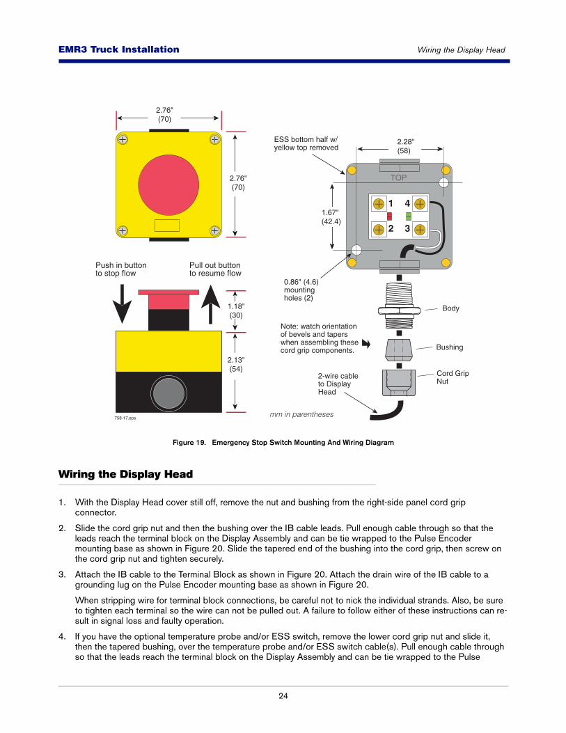
1. If you have the optional ESS switch, you should install it on the truck near the Display Head. There are two 0.181” (4.6 mm) diameter mounting holes in the ESS switch base. Also, you will need a length of 2-wire cable to connect the ESS switch to the Display Head (see Figure 19),
2. Unscrew the yellow top half of the ESS switch and put it and the gasket aside. Push out the bottom knockout in the black bottom half of the switch housing. Mount the bottom half of the switch to the truck in a place that will be quickly accessible during a delivery, using (2) 0.157” (4 mm) screws. Screw the cord grip fitting from the kit into the knockout in the switch’s bottom half. Loosen the cord grip nut/bushing and push one end of the 2-wire (black and white) cable through the cord grip fitting and into the switch housing.
3. Connect the black wire of the cable to the #4 terminal of the ESS switch assembly and the white wire of the cable to the #3 terminal of the ESS switch assembly. Tighten the cord grip nut to seal the cable.
4. Position the ESS switch’s yellow top half on the mounted black half, being careful that the gasket is in place. Screw in the four screws in the yellow half of the housing.
24
EMR3 - Truck InstallationsEMR3 Truck Installation Wiring the Display Head
Figure 19. Emergency Stop Switch Mounting And Wiring Diagram
Wiring the Display Head
1. With the Display Head cover still off, remove the nut and bushing from the right-side panel cord grip connector.
2. Slide the cord grip nut and then the bushing over the IB cable leads. Pull enough cable through so that the leads reach the terminal block on the Display Assembly and can be tie wrapped to the Pulse Encoder mounting base as shown in Figure 20. Slide the tapered end of the bushing into the cord grip, then screw on the cord grip nut and tighten securely.
3. Attach the IB cable to the Terminal Block as shown in Figure 20. Attach the drain wire of the IB cable to a grounding lug on the Pulse Encoder mounting base as shown in Figure 20.
When stripping wire for terminal block connections, be careful not to nick the individual strands. Also, be sure to tighten each terminal so the wire can not be pulled out. A failure to follow either of these instructions can re-sult in signal loss and faulty operation.
4. If you have the optional temperature probe and/or ESS switch, remove the lower cord grip nut and slide it, then the tapered bushing, over the temperature probe and/or ESS switch cable(s). Pull enough cable through so that the leads reach the terminal block on the Display Assembly and can be tie wrapped to the Pulse
2.13"(54)
1.18"(30)
1.67"(42.4)
2.76"(70)
2.76"(70)
2.28"(58)
Body
0.86" (4.6)mountingholes (2)
Cord Grip Nut
Note: watch orientation of bevels and tapers when assembling these cord grip components.
Bushing
4
3
1
2
TOP
2-wire cableto DisplayHead
ESS bottom half w/yellow top removed
Push in buttonto stop flow
Pull out buttonto resume flow
758-17.epsmm in parentheses

25
EMR3 - Truck InstallationsEMR3 Truck Installation Wiring the Display Head
Encoder mounting base as shown in Figure 20. Slide the bushing into the cord grip and then screw the cord grip nut onto the cord grip and tighten securely.
Attach the shield of the temperature probe cable to a grounding lug on the Pulse Encoder mounting base.
5. Attach each wire (no polarity) of the 2-conductor Temperature Probe and/or ESS switch cable(s) as shown in Figure 20.
6. Tie wrap the IB, ESS switch, and temp probe (if installed) cables to the Pulse Encoder mounting base.
7. For Transfer Interlock applications, attach the 2-conductor cable from the switch as shown in Figure 20.
8. Replace the Display Head cover and screw in the four cover retaining bolts just enough to hold them in (the cover will be removed later for system calibration).
9. Using the tie wraps from the installation kit, attach the 4-wire cable from the Display Head to the Interconnect Box along the inside of the truck frame, to existing piping, or to the reel motor cable back to the cab. Avoid sharp bends and placements where vibration might wear through the cable. Allow ample cable length to compensate for tilt-cab trucks and to avoid putting additional stress on the assembly. Running the cable through a split loom or tubing will offer added protection from weather and abrasion. Use a rubber grommet or cord grip to line the hole where cable passes through truck cab wall or floor. Tractor-trailer installations will require detachable plugs, and either a separate tensioning device much like that used to protect air lines, or perhaps you can attach the cable to one of the existing air lines with tie wraps.
26
EMR3 - Truck InstallationsEMR3 Truck Installation C&C Mode Switch Options
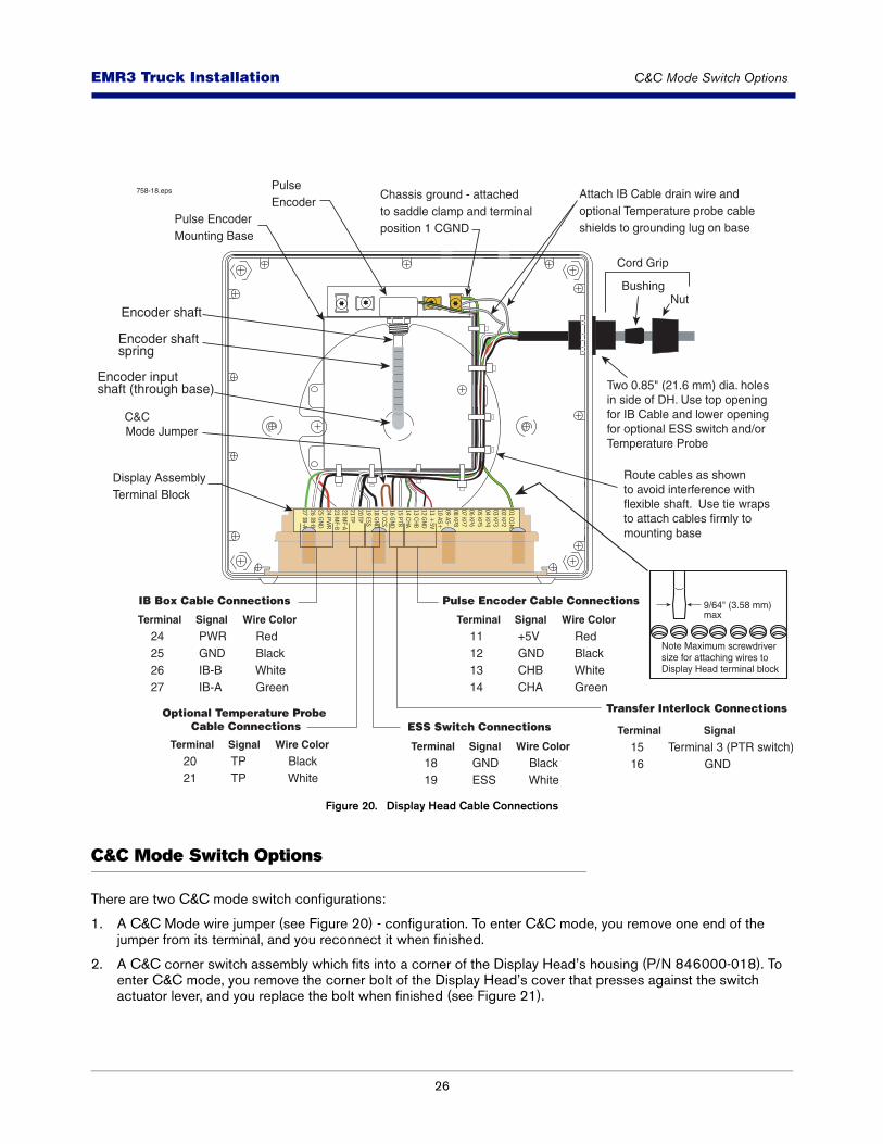
Figure 20. Display Head Cable Connections
C&C Mode Switch Options
There are two C&C mode switch configurations:
1. A C&C Mode wire jumper (see Figure 20) - configuration. To enter C&C mode, you remove one end of the jumper from its terminal, and you reconnect it when finished.
2. A C&C corner switch assembly which fits into a corner of the Display Head’s housing (P/N 846000-018). To enter C&C mode, you remove the corner bolt of the Display Head’s cover that presses against the switch actuator lever, and you replace the bolt when finished (see Figure 21).
758-18.eps
Encoder shaftspring
Encoder inputshaft (through base)
Encoder shaft
27
EMR3 - Truck InstallationsEMR3 Truck Installation Installing Optional Keypad Kit - Right or Left Side
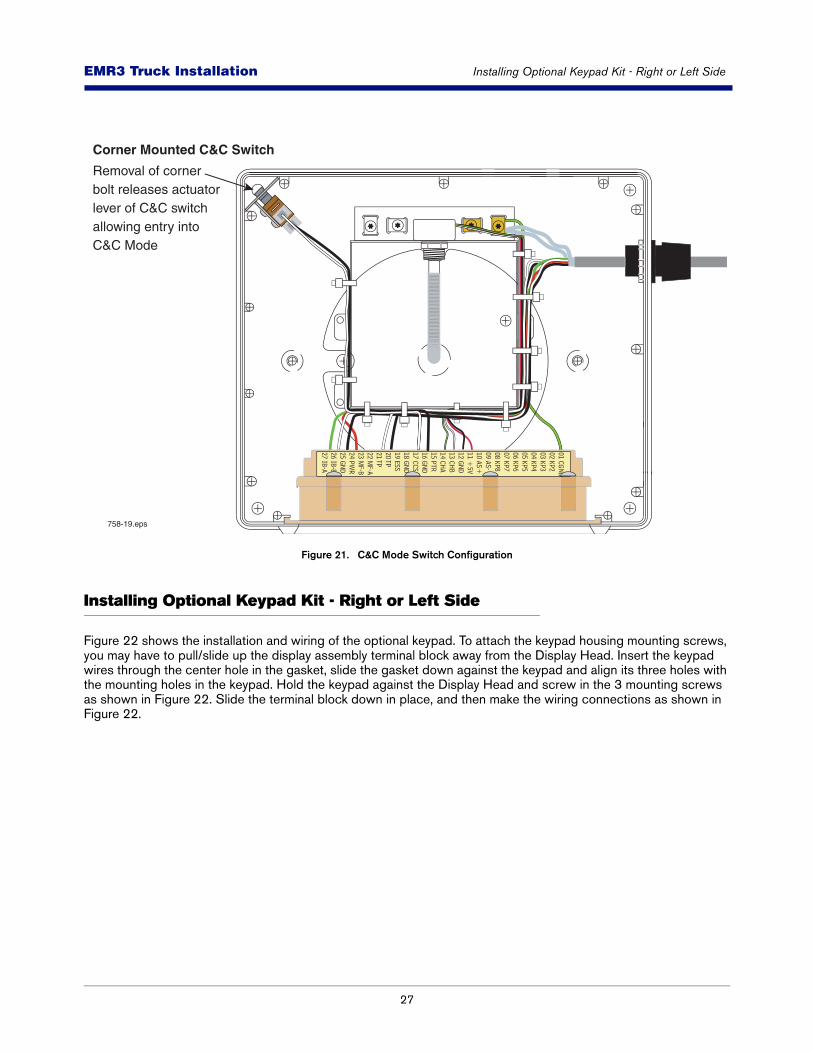
Figure 21. C&C Mode Switch Configuration
Installing Optional Keypad Kit - Right or Left Side
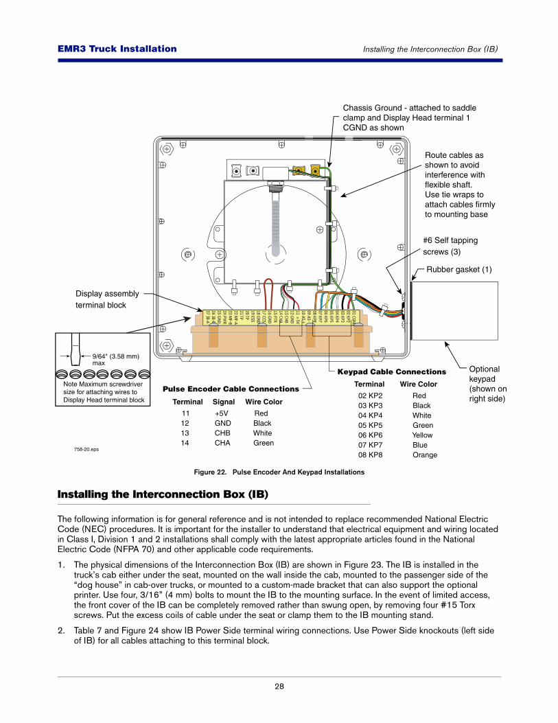
Figure 22 shows the installation and wiring of the optional keypad. To attach the keypad housing mounting screws, you may have to pull/slide up the display assembly terminal block away from the Display Head. Insert the keypad wires through the center hole in the gasket, slide the gasket down against the keypad and align its three holes with the mounting holes in the keypad. Hold the keypad against the Display Head and screw in the 3 mounting screws as shown in Figure 22. Slide the terminal block down in place, and then make the wiring connections as shown in Figure 22.
758-19.eps
Corner Mounted C&C Switch
Removal of cornerbolt releases actuator lever of C&C switchallowing entry intoC&C Mode
01 CGND02 KP203 KP304 KP405 KP506 KP607 KP708 KP809 AS-10 AS+11 +
5V12 GND13 CHB14 CHA15 PTR16 GND17 CCS18 GND19 ESS20 TP21 TP22 M
F-A23 M
F-B24 PW
R25 GND26 IB-B27 IB-A
28
EMR3 - Truck InstallationsEMR3 Truck Installation Installing the Interconnection Box (IB)
Figure 22. Pulse Encoder And Keypad Installations
Installing the Interconnection Box (IB)
The following information is for general reference and is not intended to replace recommended National Electric Code (NEC) procedures. It is important for the installer to understand that electrical equipment and wiring located in Class I, Division 1 and 2 installations shall comply with the latest appropriate articles found in the National Electric Code (NFPA 70) and other applicable code requirements.
1. The physical dimensions of the Interconnection Box (IB) are shown in Figure 23. The IB is installed in the truck’s cab either under the seat, mounted on the wall inside the cab, mounted to the passenger side of the “dog house” in cab-over trucks, or mounted to a custom-made bracket that can also support the optional printer. Use four, 3/16” (4 mm) bolts to mount the IB to the mounting surface. In the event of limited access, the front cover of the IB can be completely removed rather than swung open, by removing four #15 Torx screws. Put the excess coils of cable under the seat or clamp them to the IB mounting stand.
2. Table 7 and Figure 24 show IB Power Side terminal wiring connections. Use Power Side knockouts (left side of IB) for all cables attaching to this terminal block.
758-20.eps
Terminal
11 12 13 14
Wire Color
Red Black White Green
Signal
+5V GND CHB CHA
Terminal
02 KP2 03 KP3 04 KP4 05 KP5 06 KP6 07 KP7 08 KP8
Wire Color
Red Black White Green Yellow Blue Orange
Pulse Encoder Cable Connections
Keypad Cable Connections
Display assemblyterminal block
Chassis Ground - attached to saddle clamp and Display Head terminal 1 CGND as shown
Route cables as shown to avoidinterference withflexible shaft. Use tie wraps to attach cables firmlyto mounting base
#6 Self tapping screws (3)
Optionalkeypad (shown onright side)
Rubber gasket (1)
01 CGND02 KP203 KP304 KP405 KP506 KP607 KP708 KP809 AS-10 AS+11 +
5V12 GND13 CHB14 CHA15 PTR16 GND17 CCS18 GND19 ESS20 TP21 TP22 M
F-A23 M
F-B24 PW
R25 GND26 IB-B27 IB-A
9/64" (3.58 mm) max
Note Maximum screwdriver size for attaching wires to Display Head terminal block

29
EMR3 - Truck InstallationsEMR3 Truck Installation Input Power – Critical Ground Connection
3. Run the power cable from the truck fuse block or ignition switch to the IB. Clamp the power wire at suitable intervals between the power source and the IB.
Before connecting the truck power wiring, verify the following:
a.Electrical system has a negative ground.
b.Battery terminals and cables are in good condition.
c.Alternator current output is sufficient to supply EMR3 System current requirement of 5 amperes.
Attach the wire from truck ground to the Ground terminal of the Power Side terminal block. Also attach the wire from the truck’s Accessory (ACC) circuit to the V+ terminal of the terminal block.
4. Table 8 and Figure 24 show the IB intrinsically safe terminal wiring connections. Use Intrinsically Safe Side knockouts (right side of IB under cover) for Display Head cable entries. The drain wire in each Display Head cable must be connected to the adjacent chassis ground clamp.
IB POWER FUSE
IB boxes can have either a replaceable power fuse which is located on the IB box’s printed circuit board (replace with a 5A, Slo Blo, Type T 5x20mm, Littelfuse #218005 [V-R P/N 576010-973]), or a non-replaceable power fuse which will automatically reset itself after a short cooling-off period following the power surge which caused it to open.
The IB box is not rated for mounting in outdoor locations. The IB box can be mounted only in a protected enclosure or protected location.
Input Power – Critical Ground Connection
On some vehicles, the battery minus terminal, BAT(-), may not be common with the chassis ground or the defined vehicle ground located in either the accessory panel or in the power distribution box. In this case, directly run the ground connection, for Input Power, located on the top of the terminal strip inside the Interconnection Box, directly to the BAT(-) terminal connection point.
Proper operation of the EMR3 hardware depends on the quality of the ground connection from the Interconnection Box to the source of V(+) power.
If the V(+) connection is made at the accessory panel, it should be fused at 5 amps. The installer must ensure that a minimum of 12.0 volts, between the V(+) terminal and the ground terminal, is available from the power source. If an improper ground point is used for input power to the EMR3 there may be insufficient power for the Display Head to operate properly resulting in various E## error codes or possibly a blank display.
Pay careful attention to the wiring labels on both the EMR3 Display Head and the Interconnection Box. Each connection must be made according to the wiring tables listed in this manual. Use shielded cable to connect each device to the Interconnection Box and be sure each cable jacket is resistant to gas and oil.
CAUTION! INSTALLATIONS WITH HIGH AMPERAGE DEVICES
The input power for an EMR3 must be isolated from devices that use large amounts of electric current such as reel motors. Connect the EMR3 using dedicated wiring between the voltage source and the Interconnection Box. On vehicles with multiple voltage sources it may be necessary to use a separate battery or voltage source to power the EMR3. Also, a battery isolator can be used between the voltage source and the IB to prevent voltage spikes from entering the Interconnect Box when the high amperage devices are de-energized.
30
EMR3 - Truck InstallationsEMR3 Truck Installation Input Power – Critical Ground Connection
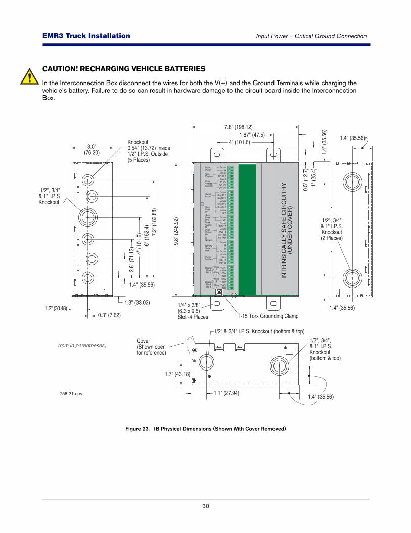
CAUTION! RECHARGING VEHICLE BATTERIES
In the Interconnection Box disconnect the wires for both the V(+) and the Ground Terminals while charging the vehicle’s battery. Failure to do so can result in hardware damage to the circuit board inside the Interconnection Box.
Figure 23. IB Physical Dimensions (Shown With Cover Removed)
3.0"(76.20)
7.8" (198.12)
9.8"
(248
.92)
1.4" (35.56)
1.3" (33.02)
2.8"
(71.
12)
4" (1
01.6
)6"
(152
.4)
7.2"
(182
.88)
1.2" (30.48)0.3" (7.62)
Knockout0.54" (13.72) Inside 1/2" I.P.S. Outside (5 Places)
1/2", 3/4"& 1" I.P.SKnockout
1/2", 3/4", & 1" I.P.S. Knockout (bottom & top)
1/2" & 3/4" I.P.S. Knockout (bottom & top)
Cover (Shown openfor reference)
0.5"
(12.
7)
1.1" (27.94)
1" (2
5.4)
1.87" (47.5)4" (101.6)
1/4" x 3/8" (6.3 x 9.5)Slot -4 Places
1.4" (35.56)
1.4" (35.56)
1.4" (35.56)
1.4"
(35.
56)
1.7" (43.18)
1/2", 3/4"& 1" I.P.S.Knockout(2 Places)
758-21.eps
T-15 Torx Grounding Clamp
INT
RIN
SIC
ALL
Y S
AF
E C
IRC
UIT
RY
(U
ND
ER
CO
VE
R)
(mm in parentheses)
31
EMR3 - Truck InstallationsEMR3 Truck Installation Input Power – Critical Ground Connection
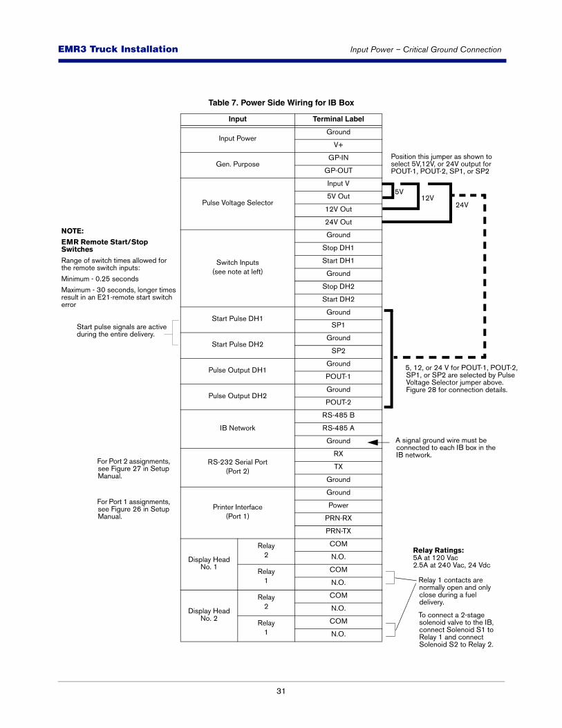
Table 7. Power Side Wiring for IB Box
Input Terminal Label
Input PowerGround
V+
Gen. PurposeGP-IN
GP-OUT
Pulse Voltage Selector
Input V
5V Out
12V Out
24V Out
Switch Inputs(see note at left)
Ground
Stop DH1
Start DH1
Ground
Stop DH2
Start DH2
Start Pulse DH1Ground
SP1
Start Pulse DH2Ground
SP2
Pulse Output DH1Ground
POUT-1
Pulse Output DH2Ground
POUT-2
IB Network
RS-485 B
RS-485 A
Ground
RS-232 Serial Port(Port 2)
RX
TX
Ground
Printer Interface(Port 1)
Ground
Power
PRN-RX
PRN-TX
Display Head No. 1
Relay2
COM
N.O.
Relay1
COM
N.O.
Display Head No. 2
Relay2
COM
N.O.
Relay1
COM
N.O.
A signal ground wire must be connected to each IB box in the IB network.
Position this jumper as shown to select 5V,12V, or 24V output for POUT-1, POUT-2, SP1, or SP2
5V12V
24V
NOTE:
EMR Remote Start/Stop Switches
Range of switch times allowed for the remote switch inputs:
Minimum - 0.25 seconds
Maximum - 30 seconds, longer times result in an E21-remote start switch error
5, 12, or 24 V for POUT-1, POUT-2, SP1, or SP2 are selected by Pulse Voltage Selector jumper above. Figure 28 for connection details.
For Port 2 assignments, see Figure 27 in Setup Manual.
For Port 1 assignments, see Figure 26 in Setup Manual.
Relay 1 contacts are normally open and only close during a fuel delivery.
To connect a 2-stage solenoid valve to the IB, connect Solenoid S1 to Relay 1 and connect Solenoid S2 to Relay 2.
Relay Ratings:5A at 120 Vac2.5A at 240 Vac, 24 Vdc
Start pulse signals are active during the entire delivery.
32
EMR3 - Truck InstallationsEMR3 Truck Installation Input Power – Critical Ground Connection
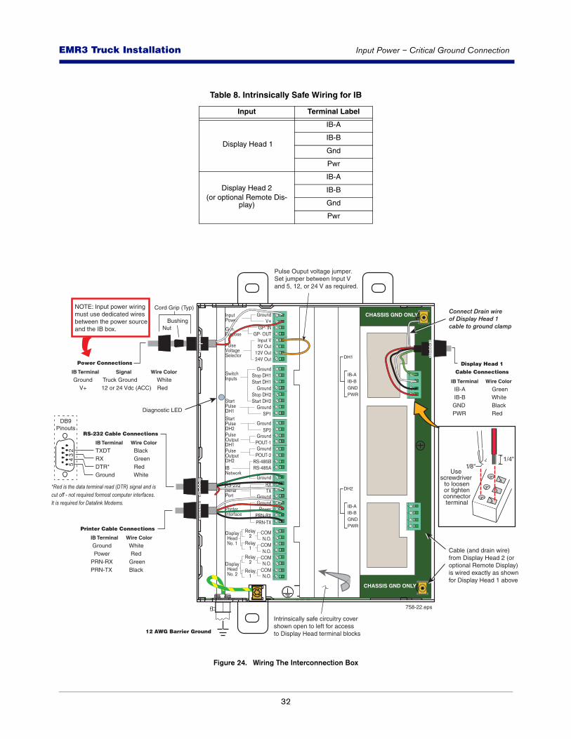
Figure 24. Wiring The Interconnection Box
Table 8. Intrinsically Safe Wiring for IB
Input Terminal Label
Display Head 1
IB-A
IB-B
Gnd
Pwr
Display Head 2(or optional Remote Dis-
play)
IB-A
IB-B
Gnd
Pwr
IB-AIB-BGNDPWR
DH1
IB-AIB-BGNDPWR
DH2
758-22.eps
BushingNut
Cord Grip (Typ)
Intrinsically safe circuitry covershown open to left for accessto Display Head terminal blocks
Cable (and drain wire)from Display Head 2 (or optional Remote Display)is wired exactly as shown for Display Head 1 above
Connect Drain wireof Display Head 1cable to ground clamp
Pulse Ouput voltage jumper. Set jumper between Input V and 5, 12, or 24 V as required.
NOTE: Input power wiring must use dedicated wires between the power sourceand the IB box.
IB Terminal
Ground V+
Wire Color
White Red
Signal
Truck Ground 12 or 24 Vdc (ACC)
Power Connections
IB Terminal
Ground PowerPRN-RXPRN-TX
Wire Color
White Red Green Black
Printer Cable Connections
IB Terminal
TXDT RX DTR*Ground
Wire Color
Black Green Red White
RS-232 Cable Connections
IB Terminal
IB-A IB-B GND PWR
Wire Color
Green White Black Red
Display Head 1 Cable Connections
Diagnostic LED
CHASSIS GND ONLY
CHASSIS GND ONLY
*Red is the data terminal read (DTR) signal and is cut off - not required formost computer interfaces. It is required for Datalink Modems.
12 AWG Barrier Ground
1/4"1/8"
Use screwdriver
to loosenor tightenconnectorterminal
32
54
DB9Pinouts
33
EMR3 - Truck InstallationsEMR3 Truck Installation 3-Way Safety Valve for Truck LP Gas Systems
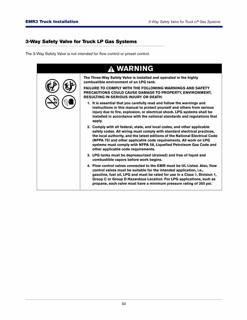
3-Way Safety Valve for Truck LP Gas Systems
The 3-Way Safety Valve is not intended for flow control or preset control.
WARNINGThe Three-Way Safety Valve is installed and operated in the highly combustible environment of an LPG tank.
FAILURE TO COMPLY WITH THE FOLLOWING WARNINGS AND SAFETY PRECAUTIONS COULD CAUSE DAMAGE TO PROPERTY, ENVIRONMENT, RESULTING IN SERIOUS INJURY OR DEATH.
1. It is essential that you carefully read and follow the warnings and instructions in this manual to protect yourself and others from serious injury due to fire, explosion, or electrical shock. LPG systems shall be installed in accordance with the national standards and regulations that apply.
2. Comply with all federal, state, and local codes, and other applicable safety codes. All wiring must comply with standard electrical practices, the local authority, and the latest editions of the National Electrical Code (NFPA 70) and other applicable code requirements. All work on LPG systems must comply with NFPA 58, Liquefied Petroleum Gas Code and other applicable code requirements.
3. LPG tanks must be depressurized (drained) and free of liquid and combustible vapors before work begins.
4. Flow control valves connected to the EMR must be UL Listed. Also, flow control valves must be suitable for the intended application, i.e., gasoline, fuel oil, LPG and must be rated for use in a Class 1, Division 1, Group C or Group D Hazardous Location. For LPG applications, such as propane, each valve must have a minimum pressure rating of 350 psi.
34
EMR3 - Truck InstallationsEMR3 Truck Installation 3-Way Safety Valve for Truck LP Gas Systems
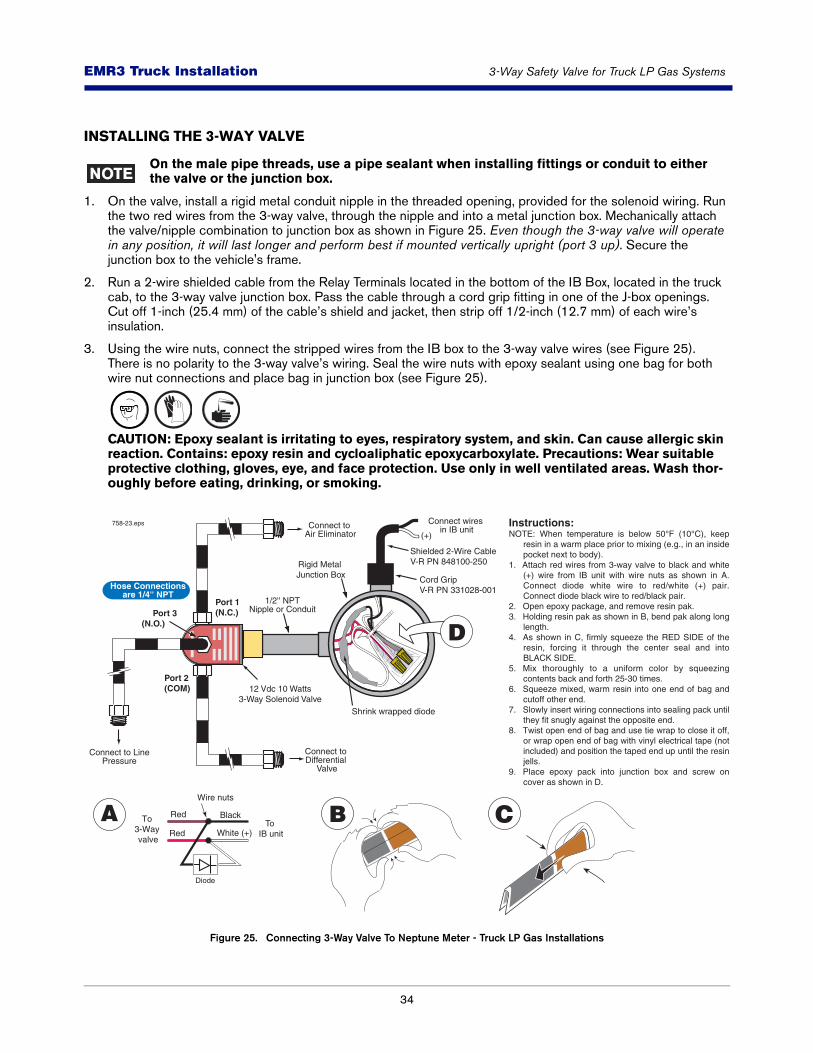
INSTALLING THE 3-WAY VALVE
On the male pipe threads, use a pipe sealant when installing fittings or conduit to either the valve or the junction box.
1. On the valve, install a rigid metal conduit nipple in the threaded opening, provided for the solenoid wiring. Run the two red wires from the 3-way valve, through the nipple and into a metal junction box. Mechanically attach the valve/nipple combination to junction box as shown in Figure 25. Even though the 3-way valve will operate in any position, it will last longer and perform best if mounted vertically upright (port 3 up). Secure the junction box to the vehicle's frame.
2. Run a 2-wire shielded cable from the Relay Terminals located in the bottom of the IB Box, located in the truck cab, to the 3-way valve junction box. Pass the cable through a cord grip fitting in one of the J-box openings. Cut off 1-inch (25.4 mm) of the cable’s shield and jacket, then strip off 1/2-inch (12.7 mm) of each wire’s insulation.
3. Using the wire nuts, connect the stripped wires from the IB box to the 3-way valve wires (see Figure 25). There is no polarity to the 3-way valve’s wiring. Seal the wire nuts with epoxy sealant using one bag for both wire nut connections and place bag in junction box (see Figure 25).
CAUTION: Epoxy sealant is irritating to eyes, respiratory system, and skin. Can cause allergic skin reaction. Contains: epoxy resin and cycloaliphatic epoxycarboxylate. Precautions: Wear suitable protective clothing, gloves, eye, and face protection. Use only in well ventilated areas. Wash thor-oughly before eating, drinking, or smoking.
Figure 25. Connecting 3-Way Valve To Neptune Meter - Truck LP Gas Installations
Rigid Metal Junction Box
Shrink wrapped diode
Shielded 2-Wire CableV-R PN 848100-250
Cord GripV-R PN 331028-001
Port 1(N.C.) Port 3
(N.O.)
Port 2(COM)
Hose Connectionsare 1/4'' NPT
Connect to LinePressure
Connect to Differential
Valve
12 Vdc 10 Watts3-Way Solenoid Valve
Connect to Air Eliminator
Connect wires in IB unit
1/2'' NPTNipple or Conduit
758-23.eps
Black
White (+)
To 3-Way valve
To IB unit
Red
Red
Wire nuts
Instructions:NOTE: When temperature is below 50°F (10°C), keep
resin in a warm place prior to mixing (e.g., in an inside pocket next to body).
1. Attach red wires from 3-way valve to black and white (+) wire from IB unit with wire nuts as shown in A. Connect diode white wire to red/white (+) pair. Connect diode black wire to red/black pair.
2. Open epoxy package, and remove resin pak.3. Holding resin pak as shown in B, bend pak along long
length.4. As shown in C, firmly squeeze the RED SIDE of the
resin, forcing it through the center seal and into BLACK SIDE.
5. Mix thoroughly to a uniform color by squeezing contents back and forth 25-30 times.
6. Squeeze mixed, warm resin into one end of bag and cutoff other end.
7. Slowly insert wiring connections into sealing pack until they fit snugly against the opposite end.
8. Twist open end of bag and use tie wrap to close it off, or wrap open end of bag with vinyl electrical tape (not included) and position the taped end up until the resin jells.
9. Place epoxy pack into junction box and screw on cover as shown in D.
CA
D
B
Diode
(+)
35
EMR3 - Truck InstallationsEMR3 Truck Installation 3-Way Safety Valve for Truck LP Gas Systems
4. Tighten the cable bushing nuts on the cord grip to ensure a watertight seal at the cable’s entry.
5. Remove the protective closures from the 3-way valve ports.
Neptune meters:
Connect a hose from line pressure to port 3 (normally open port) of the 3-way valve (see Figure 25). On some systems, line pressure is available at an opening in the vapor eliminator housing. Connect another hose from the 3-way valve’s port 1 (normally closed port) to the air eliminator. Connect a third hose from the 3-way valve’s port 2 (common port) to the differential valve.
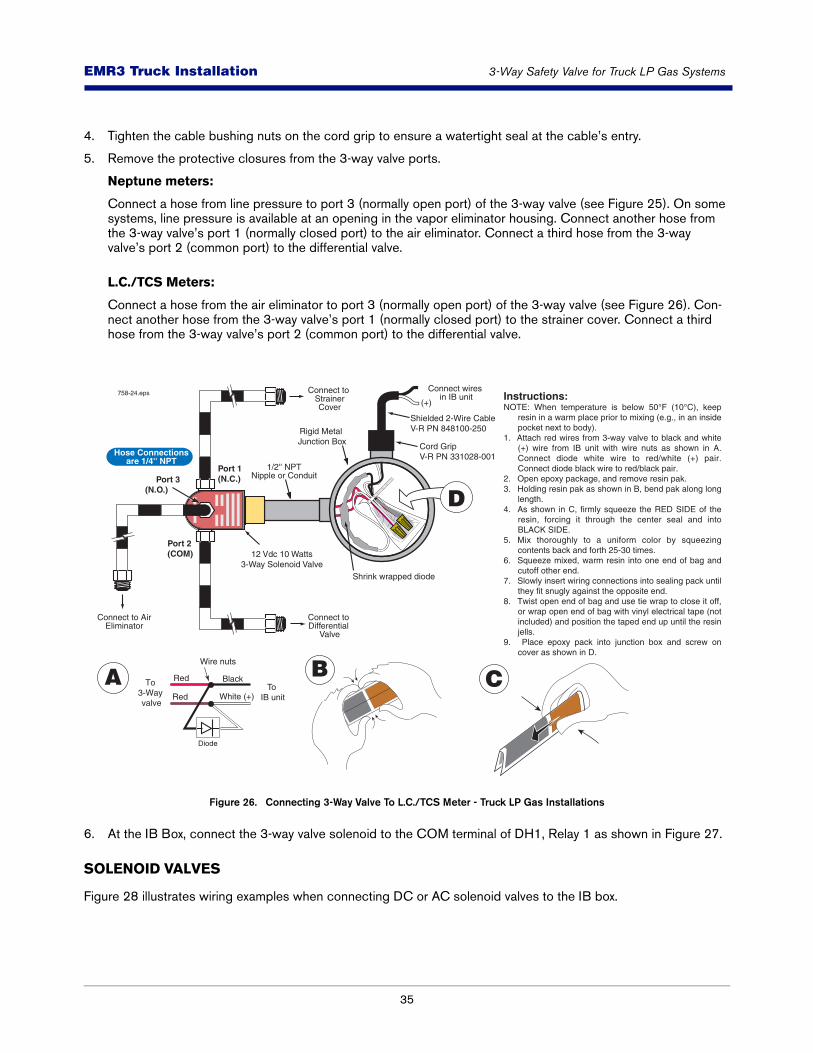
L.C./TCS Meters:
Connect a hose from the air eliminator to port 3 (normally open port) of the 3-way valve (see Figure 26). Con-nect another hose from the 3-way valve’s port 1 (normally closed port) to the strainer cover. Connect a third hose from the 3-way valve’s port 2 (common port) to the differential valve.
Figure 26. Connecting 3-Way Valve To L.C./TCS Meter - Truck LP Gas Installations
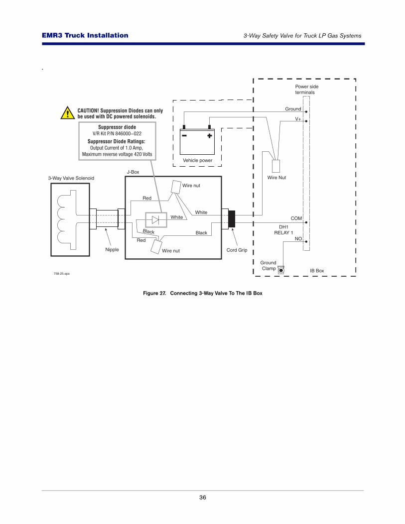
6. At the IB Box, connect the 3-way valve solenoid to the COM terminal of DH1, Relay 1 as shown in Figure 27.
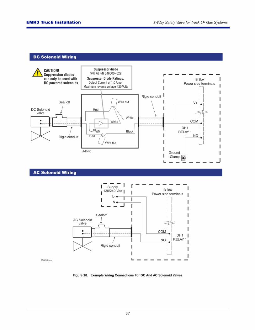
SOLENOID VALVES
Figure 28 illustrates wiring examples when connecting DC or AC solenoid valves to the IB box.
Connect to AirEliminator
Connect to Differential
Valve
Connect to StrainerCover
758-24.eps
B C
Instructions:NOTE: When temperature is below 50°F (10°C), keep
resin in a warm place prior to mixing (e.g., in an inside pocket next to body).
1. Attach red wires from 3-way valve to black and white (+) wire from IB unit with wire nuts as shown in A. Connect diode white wire to red/white (+) pair. Connect diode black wire to red/black pair.
2. Open epoxy package, and remove resin pak.3. Holding resin pak as shown in B, bend pak along long
length.4. As shown in C, firmly squeeze the RED SIDE of the
resin, forcing it through the center seal and into BLACK SIDE.
5. Mix thoroughly to a uniform color by squeezing contents back and forth 25-30 times.
6. Squeeze mixed, warm resin into one end of bag and cutoff other end.
7. Slowly insert wiring connections into sealing pack until they fit snugly against the opposite end.
8. Twist open end of bag and use tie wrap to close it off, or wrap open end of bag with vinyl electrical tape (not included) and position the taped end up until the resin jells.
9. Place epoxy pack into junction box and screw on cover as shown in D.
Rigid Metal Junction Box
Shrink wrapped diode
Shielded 2-Wire CableV-R PN 848100-250
Cord GripV-R PN 331028-001
Port 1(N.C.) Port 3
(N.O.)
Port 2(COM)
Hose Connectionsare 1/4'' NPT
12 Vdc 10 Watts3-Way Solenoid Valve
Connect wires in IB unit
1/2'' NPTNipple or Conduit
Black
White (+)
To 3-Way valve
To IB unit
Red
Red
Wire nuts
A
D
Diode
(+)
36
EMR3 - Truck InstallationsEMR3 Truck Installation 3-Way Safety Valve for Truck LP Gas Systems
.
Figure 27. Connecting 3-Way Valve To The IB Box
V+
Ground
DH1RELAY 1
Power sideterminals
Wire Nut
Wire nut
Red
Red
BlackBlack
WhiteWhite
Wire nut
3-Way Valve Solenoid
IB Box
Cord Grip
Vehicle power
NO
COM
758-25.eps
Nipple
J-Box
Ground Clamp
CAUTION! Suppression Diodes can only be used with DC powered solenoids.
Suppressor diodeV/R Kit P/N 846000-022
Suppressor Diode Ratings: Output Current of 1.0 Amp,
Maximum reverse voltage 420 Volts
37
EMR3 - Truck InstallationsEMR3 Truck Installation 3-Way Safety Valve for Truck LP Gas Systems
Figure 28. Example Wiring Connections For DC And AC Solenoid Valves
V+
DH1RELAY 1
IB BoxPower side terminals
DC Solenoidvalve
Rigid conduit
Seal off
NO
COM
J-Box Ground Clamp
Rigid conduit
LN
Supply120/240 Vac
1
DH1RELAY 1
IB BoxPower side terminals
AC Solenoidvalve
NO
COM
Rigid conduit
Sealoff
AC Solenoid Wiring
DC Solenoid Wiring
758-35.eps
Wire nut
Red
Red
BlackBlack
WhiteWhite
Wire nut
Suppressor diodeV/R Kit P/N 846000-022
Suppressor Diode Ratings: Output Current of 1.0 Amp,
Maximum reverse voltage 420 Volts
CAUTION! Suppression diodes can only be used with DC powered solenoids.
38
EMR3 - Truck InstallationsEMR3 Truck Installation Installing the Temperature Probe (Optional)
Installing the Temperature Probe (Optional)
1. Locate the thermowell in the metering system (see Figure 29).
Figure 29. Example Thermowell Installation
2. The thermistor should be verified prior to installation. Reference section “Temperature Measurement and Calibration” for verification procedure.
3. If a mechanical (or other) temperature compensator is being replaced, remove the temperature sensing element for the thermowell.
Remove or disable the mechanical compensator. The EMR3 will not work with mechani-cal temperature compensation and trying to do so will result in inaccurate deliveries.
4. Install the temperature probe in the thermowell. It is highly recommended that the drywell be full at the time of probe installation for best results. Use a thermo-conductive liquid such as antifreeze (ethelene glycol) or any non-freezing thermo-compound.
A second port may not be available on all meters (which may be required during flow meter proving). Check with the local inspector prior to flow meter proving.
Use this port for OptionalV-R Thermowell
Display Head
758-4.eps
START
FINISH
MODE PRESET
NEXT
ENTER
VOLUME CURRENCY RATE SETUP
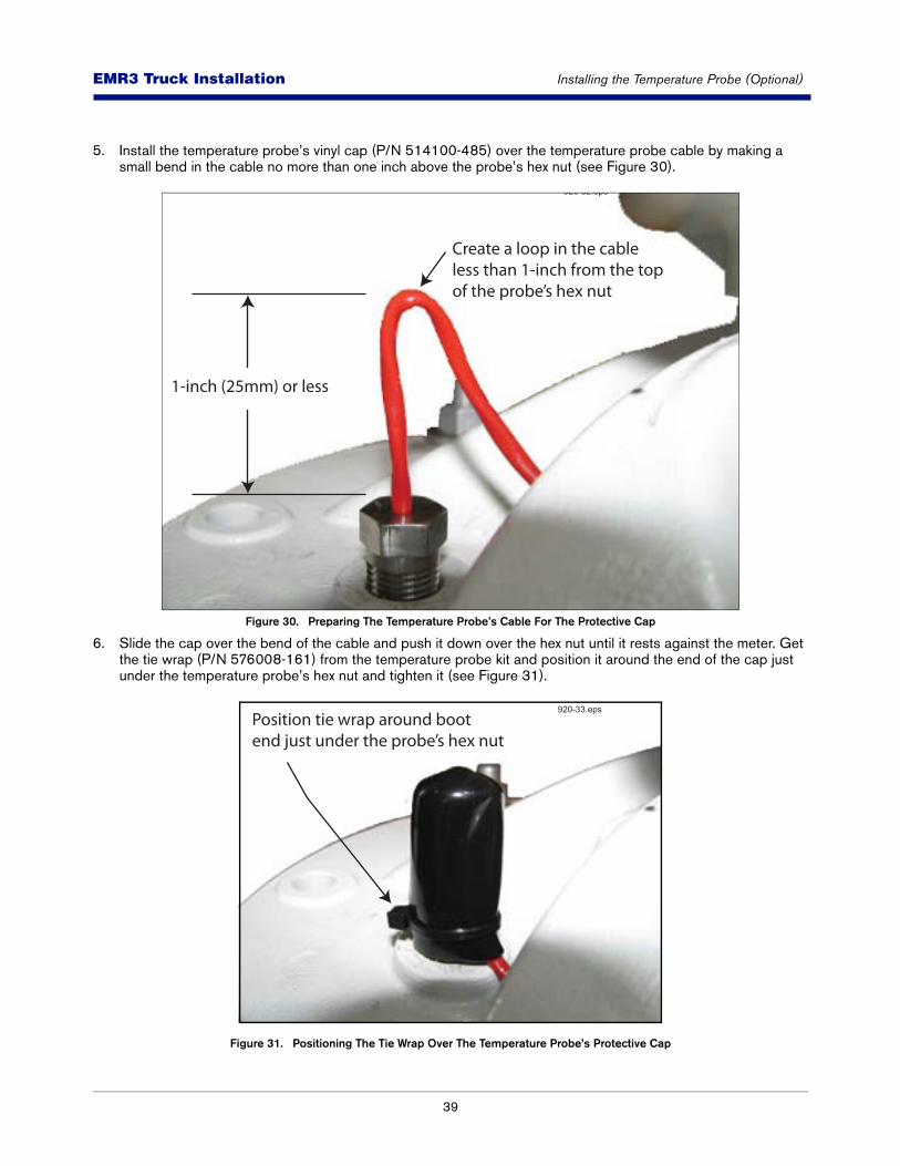
39
EMR3 - Truck InstallationsEMR3 Truck Installation Installing the Temperature Probe (Optional)
5. Install the temperature probe’s vinyl cap (P/N 514100-485) over the temperature probe cable by making a small bend in the cable no more than one inch above the probe’s hex nut (see Figure 30).
Figure 30. Preparing The Temperature Probe’s Cable For The Protective Cap
6. Slide the cap over the bend of the cable and push it down over the hex nut until it rests against the meter. Get the tie wrap (P/N 576008-161) from the temperature probe kit and position it around the end of the cap just under the temperature probe’s hex nut and tighten it (see Figure 31).
Figure 31. Positioning The Tie Wrap Over The Temperature Probe’s Protective Cap
Create a loop in the cableless than 1-inch from the top of the probe’s hex nut
1-inch (25mm) or less
920-32.eps
Position tie wrap around bootend just under the probe’s hex nut
920-33.eps
40
EMR3 - Truck InstallationsEMR3 Truck Installation Installing the Optional Slip Printer
TEMPERATURE PROBE WIRE DESCRIPTION
To ensure the best operating systems available, Veeder-Root REQUIRES the use of shielded cable (P/N 848100-250) when wiring a Temperature Probe (maximum length 50 feet [15.2 m]). In these installations, shielded cable must be rated less than 100 picofarad per foot and be manufactured with a material suitable for the environment, such as Belden™ 83552 or equivalent.
Installing the Optional Slip Printer
The Epson TM-295 dot matrix slip printer is attached with self-adhesive Velcro strips to a customer supplied mounting plate or printer stand located somewhere in the truck’s cab.
Veeder-Root recommends that you purchase an off-the-shelf assembly on which to mount the printer. A suggested vendor for in-vehicle mounting hardware is Signal Measurement Corporation (SMC). You can phone them at (800) 527-1079, or write them at 12519 Wanda Lane, Magnolia, TX 77355, or contact their web site at www.smc-corp.com for pricing or more information.
Depending on your cab type (high cab or low cab) the following SMC printer stand parts should satisfy your printer mounting needs:
*Use Loctite® 243 Threadlocker® on all printer stand mounting bolts. (Loctite and 243 Threadlocker are registered trademarks of Loctite Corporation.)
A power/data cable and three 2” x 3” (50 x 75 mm) Velcro strips are included in the printer kit. Figure 32 shows the front panel lights and controls, and the rear panel connections to the TM-295 Slip printer and illustrates the TM-295 printer’s address code setup for DIP switch 3 (which must be set as shown or it will not work) and suggested positions for the Velcro strips. Remove the rubber feet from the base of the printer to permit maximum contact between the Velcro strips and the mounting plate.
Table 9. High-Cab Installation*
Item SMC P/N
Base plate ZPLT-1
Pillar stack PS12-A
Swivel stand VMRU-9
Removable platform VMI-L0
Table 10. Low-Cab Installation*
Item SMC P/N
Base plate ZPLT-1
Pillar stack PS12-A
Removable platform VMI-L0
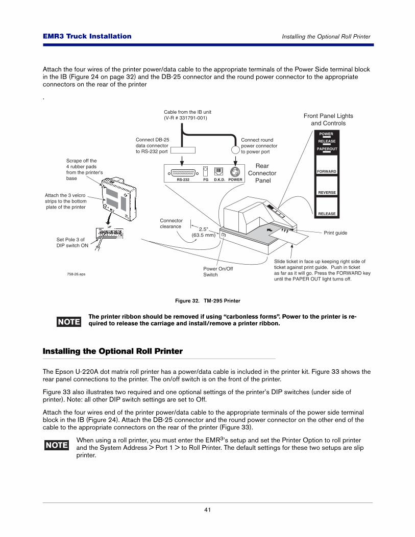
41
EMR3 - Truck InstallationsEMR3 Truck Installation Installing the Optional Roll Printer
Attach the four wires of the printer power/data cable to the appropriate terminals of the Power Side terminal block in the IB (Figure 24 on page 32) and the DB-25 connector and the round power connector to the appropriate connectors on the rear of the printer
.
Figure 32. TM-295 Printer
The printer ribbon should be removed if using “carbonless forms”. Power to the printer is re-quired to release the carriage and install/remove a printer ribbon.
Installing the Optional Roll Printer
The Epson U-220A dot matrix roll printer has a power/data cable is included in the printer kit. Figure 33 shows the rear panel connections to the printer. The on/off switch is on the front of the printer.
Figure 33 also illustrates two required and one optional settings of the printer’s DIP switches (under side of printer). Note: all other DIP switch settings are set to Off.
Attach the four wires end of the printer power/data cable to the appropriate terminals of the power side terminal block in the IB (Figure 24). Attach the DB-25 connector and the round power connector on the other end of the cable to the appropriate connectors on the rear of the printer (Figure 33).
When using a roll printer, you must enter the EMR3’s setup and set the Printer Option to roll printer and the System Address > Port 1 > to Roll Printer. The default settings for these two setups are slip printer.
POWER
RELEASE
PAPEROUT
REVERSE
FORWARD
RELEASE
RS-232 FG D.K.D. POWER
Rear Connector
Panel
Front Panel Lightsand Controls
758-26.epsPower On/Off Switch
Connect round power connector to power port
Connect DB-25 data connector to RS-232 port
Cable from the IB unit(V-R # 331791-001)
Slide ticket in face up keeping right side of ticket against print guide. Push in ticketas far as it will go. Press the FORWARD keyuntil the PAPER OUT light turns off.
Print guide2.5"
(63.5 mm)
Connectorclearance
Set Pole 3 of DIP switch ON
Attach the 3 velcro strips to the bottomplate of the printer
Scrape off the 4 rubber padsfrom the printer's base
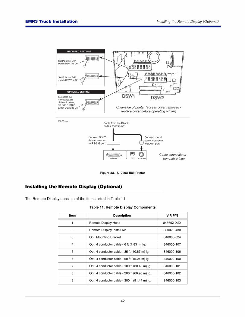
42
EMR3 - Truck InstallationsEMR3 Truck Installation Installing the Remote Display (Optional)
Figure 33. U-220A Roll Printer
Installing the Remote Display (Optional)
The Remote Display consists of the items listed in Table 11:
Table 11. Remote Display Components
Item Description V-R P/N
1 Remote Display Head 84569X-X2X
2 Remote Display Install Kit 330020-430
3 Opt. Mounting Bracket 846000-024
4 Opt. 4 conductor cable - 6 ft (1.83 m) lg. 846000-107
5 Opt. 4 conductor cable - 35 ft (10.67 m) lg. 846000-106
6 Opt. 4 conductor cable - 50 ft (15.24 m) lg. 846000-100
7 Opt. 4 conductor cable - 100 ft (30.48 m) lg. 846000-101
8 Opt. 4 conductor cable - 200 ft (60.96 m) lg. 846000-102
9 Opt. 4 conductor cable - 300 ft (91.44 m) lg. 846000-103
RS-232 DK DC24-30V
Cable connections - beneath printer
Underside of printer (access cover removed -replace cover before operating printer)
Connect round power connector to power port
Connect DB-25 data connector to RS-232 port
Cable from the IB unit(V-R # 331791-001)
Set Pole 3 of DIPswitch DSW1 to ON
1 2
ON
3 4 5 6 7 8 9 10
Set Pole 1 of DIPswitch DSW2 to ON
1
ON
2 3 4 5 6 7 8 9 10
To enable the Autocut featureof the roll printer,set Pole 2 of DIPswitch DSW2 to ON
ON
2 3 4 5 6 7 8 9 10
REQUIRED SETTINGS
OPTIONAL SETTING
758-36.eps

43
EMR3 - Truck InstallationsEMR3 Truck Installation Installing the Remote Display (Optional)
Figure 34 shows the Remote Display assembly and Figure 36 shows how to wire the display to the Interconnection Box. You can mount the display on a wall or dashboard of a truck, a wall in a building, or outside in a hazardous location. Use appropriate fasteners in any of the pre-drilled holes in the base of the optional bracket when attaching the bracket to the mounting surface. Adjust the angle of the display by loosening the side bolts and rotating the unit to the desired position.
Following wiring routing precautions and procedures discussed earlier for the meter mounted Display Head, connect the Remote Display to the Interconnection Box. Wiring connections at the Remote Display are shown in Figure 36. Install optional cord grip fitting in rear of Remote Display for cable egress. Wiring connections at the IB are to the identical terminals of the unused Display Head terminal block.
If your Remote Display does not have the front cover accessible push button C&C mode switch, a C&C sealable switch kit (P/N 330020-507) is available. The switch replaces an internal jumper (between terminals 16 GND and 17 CSS) and is installed on the front panel of the Remote Display. The installer will have to drill a hole in the front cover of the display for this switch assembly, then install the switch as shown in Figure 35. A template for locating the C&C mode switch hole is provided in Appendix B of this manual. These bolt heads have been drilled through for sealing wire.
10 Opt. 4 conductor cable - 400 ft (121.92 m) lg. 846000-104
11 Opt. 4 conductor cable - 500 ft (152.4 m) lg. 846000-105
Table 11. Remote Display Components
Item Description V-R P/N
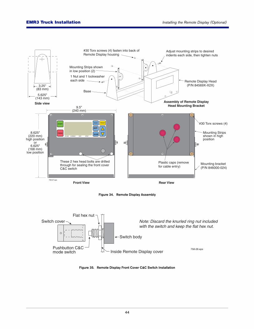
44
EMR3 - Truck InstallationsEMR3 Truck Installation Installing the Remote Display (Optional)
Figure 34. Remote Display Assembly
Figure 35. Remote Display Front Cover C&C Switch Installation
START
FINISH
MODE PRESET
NEXT
ENTER
VOLUME CURRENCY RATE SETUP
Front View Rear View
Mounting bracket(P/N 846000-024)
Plastic caps (removefor cable entry)
These 2 hex head bolts are drilled through for sealing the front cover C&C switch
#30 Torx screws (4)
758-27.eps
#30 Torx screws (4) fasten into back ofRemote Display housing
Adjust mounting strips to desiredindents each side, then tighten nuts
Mounting Strips shown in low position (2)
1 Nut and 1 lockwashereach side
Base
Mounting Stripsshown in high position
Assembly of Remote Display Head Mounting Bracket
Side view
8.625"(220 mm)
high positionor
6.625"(168 mm)
low position
9.5"(240 mm)
3.25"(83 mm)
5.625"(143 mm)
Remote Display Head(P/N 84569X-X2X)
Switch coverFlat hex nut
Switch body
Note: Discard the knurled ring nut includedwith the switch and keep the flat hex nut.
Inside Remote Display coverPushbutton C&Cmode switch
758-28.eps
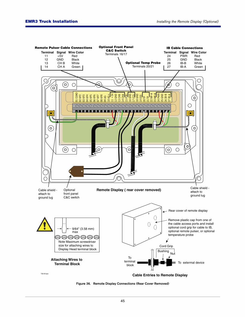
45
EMR3 - Truck InstallationsEMR3 Truck Installation Installing the Remote Display (Optional)
Figure 36. Remote Display Connections (Rear Cover Removed)
758-29.eps
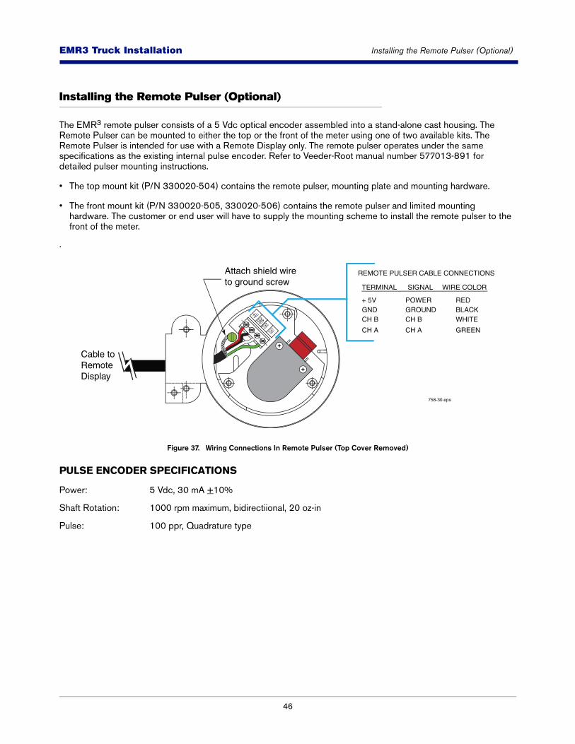
46
EMR3 - Truck InstallationsEMR3 Truck Installation Installing the Remote Pulser (Optional)
Installing the Remote Pulser (Optional)
The EMR3 remote pulser consists of a 5 Vdc optical encoder assembled into a stand-alone cast housing. The Remote Pulser can be mounted to either the top or the front of the meter using one of two available kits. The Remote Pulser is intended for use with a Remote Display only. The remote pulser operates under the same specifications as the existing internal pulse encoder. Refer to Veeder-Root manual number 577013-891 for detailed pulser mounting instructions.
• The top mount kit (P/N 330020-504) contains the remote pulser, mounting plate and mounting hardware.
• The front mount kit (P/N 330020-505, 330020-506) contains the remote pulser and limited mounting hardware. The customer or end user will have to supply the mounting scheme to install the remote pulser to the front of the meter.
.
Figure 37. Wiring Connections In Remote Pulser (Top Cover Removed)
PULSE ENCODER SPECIFICATIONS
Power: 5 Vdc, 30 mA +10%
Shaft Rotation: 1000 rpm maximum, bidirectiional, 20 oz-in
Pulse: 100 ppr, Quadrature type
758-30.eps
+V GND CH B CH A
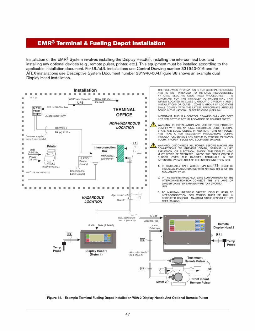
47
EMR3 Terminal & Fueling Depot Installation
Installation of the EMR3 System involves installing the Display Head(s), installing the interconnect box, and installing any optional devices (e.g., remote pulser, printer, etc.). This equipment must be installed according to the applicable installation document. For UL/cUL installations use Control Drawing number 331940-016 and for ATEX installations use Descriptive System Document number 331940-004.Figure 38 shows an example dual Display Head installation.
Figure 38. Example Terminal Fueling Depot Installation With 2 Display Heads And Optional Remote Pulser
TERMINALOFFICE
HAZARDOUS LOCATION
NON-HAZARDOUS LOCATION
Rigid conduit
InterconnectionBox
PrinterData
(RS-232)Intrinsicallysafe barrier
Data (RS-485)
Data (RS-485)
758-31.eps
12 Vdc
12 Vdc
Power
120 or 240 Vac line cord
Seal-off
UL approved 120W
120 or 240 Vac line
Blk (+) 12 Vdc
Blk/Wht (-)
12 VdcPowerSupply
VR P/N 331791-001
12 AWG Barrier Ground
Customer supplied wiring & rigid conduit
24 Vdc
TempProbe
UPSAC Power Protector
Installation THE FOLLOWING INFORMATION IS FOR GENERAL REFERENCE AND IS NOT INTENDED TO REPLACE RECOMMENDED NATIONAL ELECTRIC CODE (NEC) PROCEDURES. IT IS IMPORTANT FOR THE INSTALLER TO UNDERSTAND THAT WIRING LOCATED IN CLASS I, GROUP D DIVISION 1 AND 2 INSTALLATIONS OR CLASS I, ZONE 0, GROUP IIA LOCATIONS SHALL COMPLY WITH THE LATEST APPROPRIATE ARTICLES FOUND IN THE NATIONAL ELECTRIC CODE (NFPA 70).
IMPORTANT: THIS IS A CONTROL DRAWING ONLY AND DOES NOT REFLECT THE ACTUAL LOCATIONS OF CONDUIT ENTRY.
WARNING: IN INSTALLATION AND USE OF THIS PRODUCT, COMPLY WITH THE NATIONAL ELECTRICAL CODE; FEDERAL, STATE AND LOCAL CODES. IN ADDITION, TURN OFF POWER AND TAKE OTHER NECESSARY PRECAUTIONS DURING INSTALLATION, SERVICE AND REPAIR TO PREVENT PERSONAL INJURY, PROPERTY LOSS AND EQUIPMENT DAMAGE.
WARNING: DISCONNECT ALL POWER BEFORE MAKING ANY CONNECTIONS TO PREVENT DEATH, SERIOUS INJURY, EXPLOSION, OR ELECTRICAL SHOCK. THE DISPLAY HEAD MUST NEVER BE OPERATED UNLESS THE FRONT COVER IS CLOSED OVER THE BARRIER TERMINALS IN THE INTRINSICALLY SAFE AREA OF THE INTERCONNECTION BOX.
1. INTRINSICALLY SAFE WIRING (MARKED ) SHALL BE INSTALLED IN ACCORDANCE WITH ARTICLE 504-20 OF THE NEC, ANSI/NFPA 70.
2. IN THE NON-INTRINSICALLY SAFE COMPARTMENT OF THE INTERCONNECTION BOX, CONNECT THE #12 AWG OR LARGER DIAMETER BARRIER WIRE TO A GROUND LUG.
3. TO MAINTAIN INTRINSIC SAFETY, DISPLAY HEAD TO INTERCONNECTION BOX WIRING MUST BE RUN IN DEDICATED CONDUIT. MAXIMUM CABLE LENGTH IS 1,000 FEET (304.8 M).
Display Head 1(Meter 1)
START
FINISH
MODE PRESET
NEXT
ENTER
VOLUME CURRENCY RATE SETUP
EPSON U220 ROLL
Meter 2
Remote Display Head 2
Top mountRemote Pulser
Front mountRemote Pulser
5 VdcPulse Input
Max. cable length 35 ft. (10.6 m)
START
FINISH
MODE PRESET
NEXT
ENTER
VOLUME CURRENCY RATE SETUP
OR
Max. cable length1000 ft. (304.8 m)
TempProbe
I.S.
I.S.
I.S. I.S.
I.S.
I.S.
Connected toEarth Ground
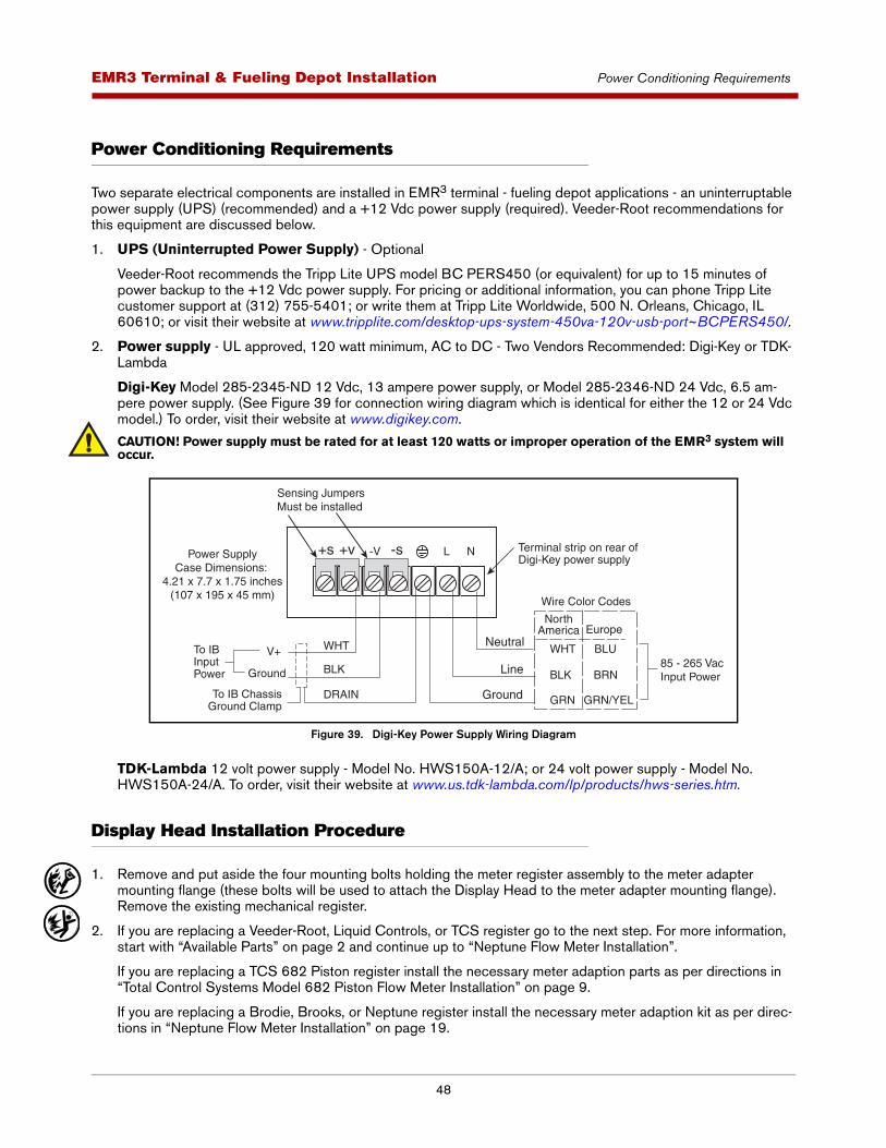
48
EMR3 - Truck InstallationsEMR3 Terminal & Fueling Depot Installation Power Conditioning Requirements
Power Conditioning Requirements
Two separate electrical components are installed in EMR3 terminal - fueling depot applications - an uninterruptable power supply (UPS) (recommended) and a +12 Vdc power supply (required). Veeder-Root recommendations for this equipment are discussed below.
1. UPS (Uninterrupted Power Supply) - Optional
Veeder-Root recommends the Tripp Lite UPS model BC PERS450 (or equivalent) for up to 15 minutes of power backup to the +12 Vdc power supply. For pricing or additional information, you can phone Tripp Lite customer support at (312) 755-5401; or write them at Tripp Lite Worldwide, 500 N. Orleans, Chicago, IL 60610; or visit their website at www.tripplite.com/desktop-ups-system-450va-120v-usb-port~BCPERS450/.
2. Power supply - UL approved, 120 watt minimum, AC to DC - Two Vendors Recommended: Digi-Key or TDK-Lambda
Digi-Key Model 285-2345-ND 12 Vdc, 13 ampere power supply, or Model 285-2346-ND 24 Vdc, 6.5 am-pere power supply. (See Figure 39 for connection wiring diagram which is identical for either the 12 or 24 Vdc model.) To order, visit their website at www.digikey.com.
CAUTION! Power supply must be rated for at least 120 watts or improper operation of the EMR3 system will occur.
Figure 39. Digi-Key Power Supply Wiring Diagram
TDK-Lambda 12 volt power supply - Model No. HWS150A-12/A; or 24 volt power supply - Model No. HWS150A-24/A. To order, visit their website at www.us.tdk-lambda.com/lp/products/hws-series.htm.
Display Head Installation Procedure
1. Remove and put aside the four mounting bolts holding the meter register assembly to the meter adapter mounting flange (these bolts will be used to attach the Display Head to the meter adapter mounting flange). Remove the existing mechanical register.
2. If you are replacing a Veeder-Root, Liquid Controls, or TCS register go to the next step. For more information, start with “Available Parts” on page 2 and continue up to “Neptune Flow Meter Installation”.
If you are replacing a TCS 682 Piston register install the necessary meter adaption parts as per directions in “Total Control Systems Model 682 Piston Flow Meter Installation” on page 9.
If you are replacing a Brodie, Brooks, or Neptune register install the necessary meter adaption kit as per direc-tions in “Neptune Flow Meter Installation” on page 19.
+s +v -V -s L N
BLK
WHT85 - 265 Vac Input PowerBLK
GRN
BLU
BRN
GRN/YELDRAINTo IB ChassisGround Clamp
WHTV+
Ground
Terminal strip on rear of Digi-Key power supply
To IBInput Power
Sensing JumpersMust be installed
Power SupplyCase Dimensions:
4.21 x 7.7 x 1.75 inches(107 x 195 x 45 mm)
NorthAmerica
Wire Color Codes
Europe
Line
Neutral
Ground
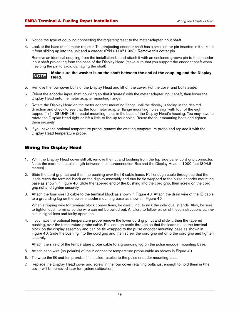
49
EMR3 - Truck InstallationsEMR3 Terminal & Fueling Depot Installation Wiring the Display Head
3. Notice the type of coupling connecting the register/preset to the meter adapter input shaft.
4. Look at the base of the meter register. The projecting encoder shaft has a small cotter pin inserted in it to keep it from sliding up into the unit and a washer (P/N 011071-933). Remove this cotter pin.
Remove an identical coupling from the installation kit and attach it with an enclosed groove pin to the encoder input shaft projecting from the base of the Display Head (make sure that you support the encoder shaft when inserting the pin to avoid damaging the shaft).
Make sure the washer is on the shaft between the end of the coupling and the Display Head.
5. Remove the four cover bolts of the Display Head and lift off the cover. Put the cover and bolts aside.
6. Orient the encoder input shaft coupling so that it ‘mates’ with the meter adapter input shaft, then lower the Display Head onto the meter adapter mounting flange.
7. Rotate the Display Head on the meter adapter mounting flange until the display is facing in the desired direction and check to see that the four meter adapter flange mounting holes align with four of the eight tapped (1/4 - 28 UNF-2B threads) mounting holes in the base of the Display Head’s housing. You may have to rotate the Display Head right or left a little to line up four holes. Reuse the four mounting bolts and tighten them securely.
8. If you have the optional temperature probe, remove the existing temperature probe and replace it with the Display Head temperature probe.
Wiring the Display Head
1. With the Display Head cover still off, remove the nut and bushing from the top side panel cord grip connector. Note: the maximum cable length between the Interconnection Box and the Display Head is 1000 feet (304.8 meters).
2. Slide the cord grip nut and then the bushing over the IB cable leads. Pull enough cable through so that the leads reach the terminal block on the display assembly and can be tie wrapped to the pulse encoder mounting base as shown in Figure 40. Slide the tapered end of the bushing into the cord grip, then screw on the cord grip nut and tighten securely.
3. Attach the four-wire IB cable to the terminal block as shown in Figure 40. Attach the drain wire of the IB cable to a grounding lug on the pulse encoder mounting base as shown in Figure 40.
When stripping wire for terminal block connections, be careful not to nick the individual strands. Also, be sure to tighten each terminal so the wire can not be pulled out. A failure to follow either of these instructions can re-sult in signal loss and faulty operation.
4. If you have the optional temperature probe remove the lower cord grip nut and slide it, then the tapered bushing, over the temperature probe cable. Pull enough cable through so that the leads reach the terminal block on the display assembly and can be tie wrapped to the pulse encoder mounting base as shown in Figure 40. Slide the bushing into the cord grip and then screw the cord grip nut onto the cord grip and tighten securely.
Attach the shield of the temperature probe cable to a grounding lug on the pulse encoder mounting base.
5. Attach each wire (no polarity) of the 2-connector temperature probe cable as shown in Figure 40.
6. Tie wrap the IB and temp probe (if installed) cables to the pulse encoder mounting base.
7. Replace the Display Head cover and screw in the four cover retaining bolts just enough to hold them in (the cover will be removed later for system calibration).
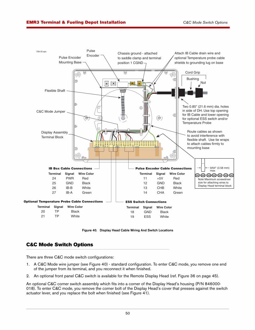
50
EMR3 - Truck InstallationsEMR3 Terminal & Fueling Depot Installation C&C Mode Switch Options
Figure 40. Display Head Cable Wiring And Switch Locations
C&C Mode Switch Options
There are three C&C mode switch configurations:
1. A C&C Mode wire jumper (see Figure 40) - standard configuration. To enter C&C mode, you remove one end of the jumper from its terminal, and you reconnect it when finished.
2. An optional front panel C&C switch is available for the Remote Display Head (ref. Figure 36 on page 45).
An optional C&C corner switch assembly which fits into a corner of the Display Head’s housing (P/N 846000-018). To enter C&C mode, you remove the corner bolt of the Display Head’s cover that presses against the switch actuator lever, and you replace the bolt when finished (see Figure 41).
758-33.eps
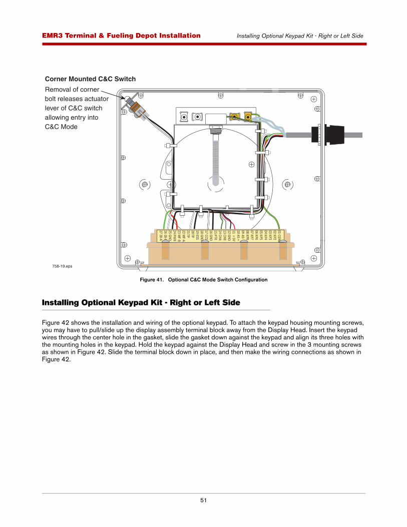
51
EMR3 - Truck InstallationsEMR3 Terminal & Fueling Depot Installation Installing Optional Keypad Kit - Right or Left Side
Figure 41. Optional C&C Mode Switch Configuration
Installing Optional Keypad Kit - Right or Left Side
Figure 42 shows the installation and wiring of the optional keypad. To attach the keypad housing mounting screws, you may have to pull/slide up the display assembly terminal block away from the Display Head. Insert the keypad wires through the center hole in the gasket, slide the gasket down against the keypad and align its three holes with the mounting holes in the keypad. Hold the keypad against the Display Head and screw in the 3 mounting screws as shown in Figure 42. Slide the terminal block down in place, and then make the wiring connections as shown in Figure 42.
758-19.eps
Corner Mounted C&C Switch
Removal of cornerbolt releases actuator lever of C&C switchallowing entry intoC&C Mode
01 CGND02 KP203 KP304 KP405 KP506 KP607 KP708 KP809 AS-10 AS+11 +
5V12 GND13 CHB14 CHA15 PTR16 GND17 CCS18 GND19 ESS20 TP21 TP22 M
F-A23 M
F-B24 PW
R25 GND26 IB-B27 IB-A
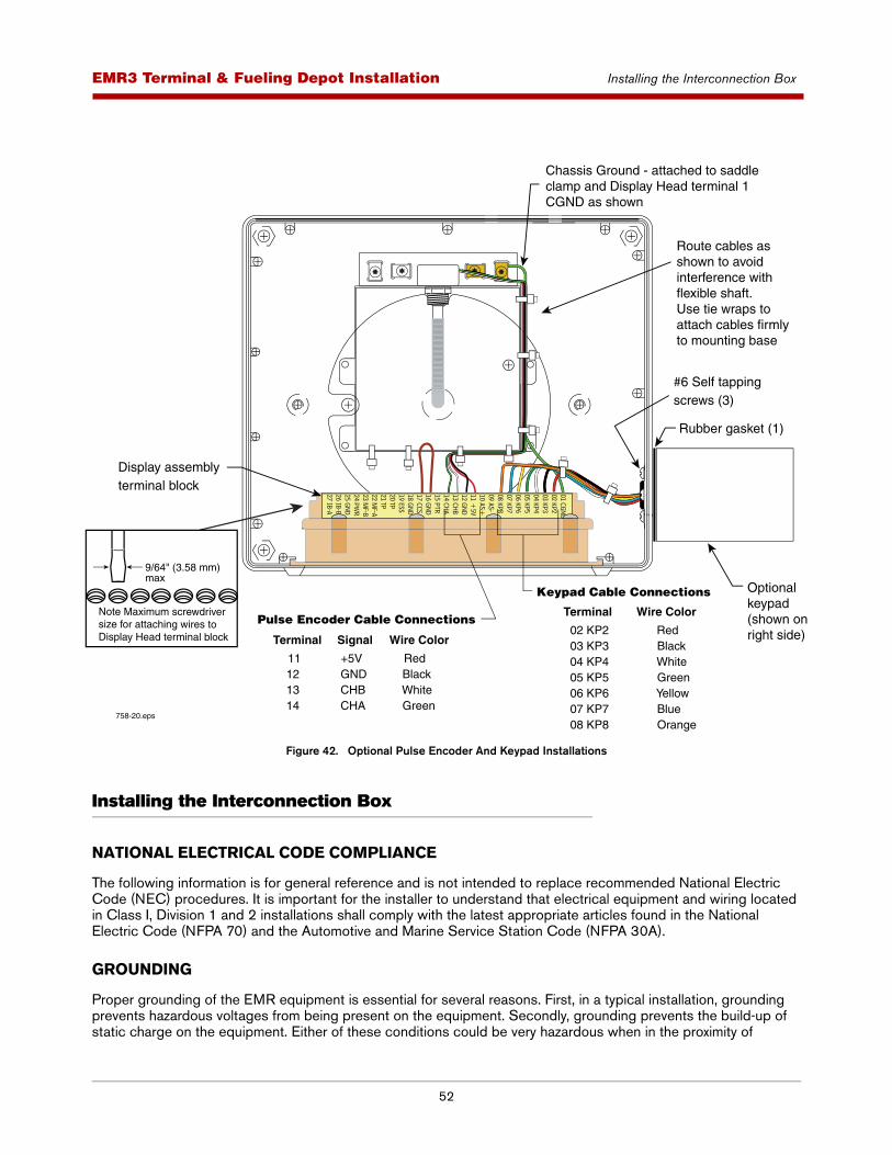
52
EMR3 - Truck InstallationsEMR3 Terminal & Fueling Depot Installation Installing the Interconnection Box
Figure 42. Optional Pulse Encoder And Keypad Installations
Installing the Interconnection Box
NATIONAL ELECTRICAL CODE COMPLIANCE
The following information is for general reference and is not intended to replace recommended National Electric Code (NEC) procedures. It is important for the installer to understand that electrical equipment and wiring located in Class I, Division 1 and 2 installations shall comply with the latest appropriate articles found in the National Electric Code (NFPA 70) and the Automotive and Marine Service Station Code (NFPA 30A).
GROUNDING
Proper grounding of the EMR equipment is essential for several reasons. First, in a typical installation, grounding prevents hazardous voltages from being present on the equipment. Secondly, grounding prevents the build-up of static charge on the equipment. Either of these conditions could be very hazardous when in the proximity of
758-20.eps
Terminal
11 12 13 14
Wire Color
Red Black White Green
Signal
+5V GND CHB CHA
Terminal
02 KP2 03 KP3 04 KP4 05 KP5 06 KP6 07 KP7 08 KP8
Wire Color
Red Black White Green Yellow Blue Orange
Pulse Encoder Cable Connections
Keypad Cable Connections
Display assemblyterminal block
Chassis Ground - attached to saddle clamp and Display Head terminal 1 CGND as shown
Route cables as shown to avoidinterference withflexible shaft. Use tie wraps to attach cables firmlyto mounting base
#6 Self tapping screws (3)
Optionalkeypad (shown onright side)
Rubber gasket (1)
01 CGND02 KP203 KP304 KP405 KP506 KP607 KP708 KP809 AS-10 AS+11 +
5V12 GND13 CHB14 CHA15 PTR16 GND17 CCS18 GND19 ESS20 TP21 TP22 M
F-A23 M
F-B24 PW
R25 GND26 IB-B27 IB-A
9/64" (3.58 mm) max
Note Maximum screwdriver size for attaching wires to Display Head terminal block

53
EMR3 - Truck InstallationsEMR3 Terminal & Fueling Depot Installation Installing the Interconnection Box
explosive mixtures found at fuel supply depots and terminals. Proper grounding requires that a very low impedance connection be made to the earth. At the distribution panel, this is accomplished by means of a dedicated conductor buried in the earth. It is imperative that all local, regional and national regulations are followed when connecting to the grounding system.
WIRE TYPE FOR NON-BONDED METALLIC OR PVC CONDUIT
Veeder-Root requires the use of shielded cable when using non-bonded metallic or PVC conduit in any portion of the wiring between the Display Head and the IB. In these installations, shielded cable must be rated less than 100 picofarad per foot and be manufactured with a material suitable for the environment.
Use either the 4-wire cable supplied by V-R, P/N 846000-1XX or any cable or wiring with rated capacitance of less than 100 picofarads per foot (per 304.8 mm). Note that conductor wire colors vary depending on the cable manufacturer (caution: the Display Head to IB wiring illustrations in this section show wire colors in the V-R cable. Alternate cables may have different wire colors).
Field wiring may be both above ground or below grade.
WIRE LENGTH
Improper system operation could result in undetected potential environmental and health hazards if the Display Head to IB wire runs exceed 1000 feet (304.8 m). Wire runs must be less than 1000 feet to be UL acceptable for this application.
MOUNTING AND WIRING THE IB UNIT
1. The physical dimensions of the Interconnection Box (IB) are shown in Figure 23 on page 30. The IB is installed in the terminal - fueling depot office. Use four, 3/16” (4 mm) bolts to mount the IB to the mounting surface.
2. Table 12 and Figure 43 show IB Power Side terminal wiring connections. Use power-side knockouts (left side of IB) for all cables attaching to this terminal block.
3. Table 13 and Figure 43 show the IB intrinsically safe terminal wiring connections. Use intrinsically-safe side knockouts (right side of IB under cover) for Display Head cable entries. The drain wire in each Display Head cable must be connected to the adjacent chassis ground clamp.
4. The printer must be within 6 feet (1.83 m) of the IB box.
All field wiring entering the IB box should be run as straight as possible from the conduit entry knockout to their designated terminal connectors.
IB POWER FUSE
IB boxes can have either a replaceable power fuse which is located on the IB box’s printed circuit board (replace with a 5A, Slo Blo, Type T 5x20mm, Littelfuse #218005 [V-R P/N 576010-973]), or a non-replaceable power fuse which will automatically reset itself after a short cooling-off period following the power surge which caused it to open.
SOLENOID VALVES
Figure 44 illustrates wiring examples when connecting dc or ac solenoid valves to the IB box.
The IB box is not rated for mounting in outdoor locations. The IB box can be mounted only in a protected enclosure or protected location.
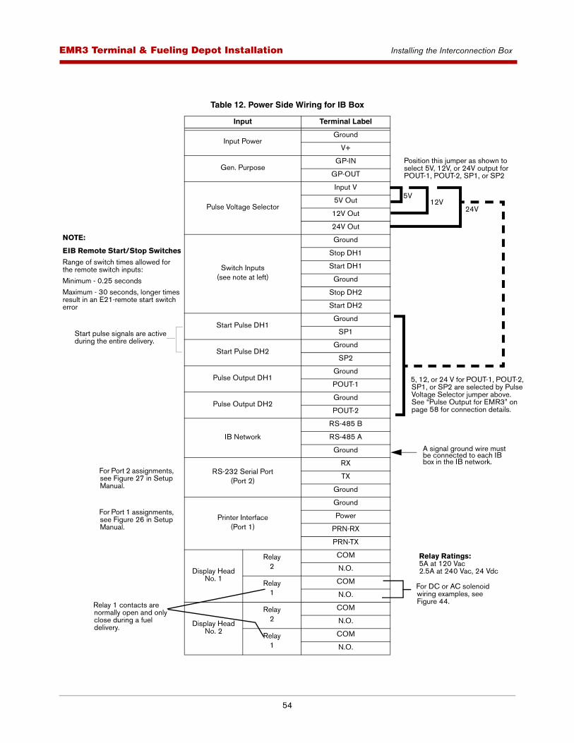
54
EMR3 - Truck InstallationsEMR3 Terminal & Fueling Depot Installation Installing the Interconnection Box
Table 12. Power Side Wiring for IB Box
Input Terminal Label
Input PowerGround
V+
Gen. PurposeGP-IN
GP-OUT
Pulse Voltage Selector
Input V
5V Out
12V Out
24V Out
Switch Inputs(see note at left)
Ground
Stop DH1
Start DH1
Ground
Stop DH2
Start DH2
Start Pulse DH1Ground
SP1
Start Pulse DH2Ground
SP2
Pulse Output DH1Ground
POUT-1
Pulse Output DH2Ground
POUT-2
IB Network
RS-485 B
RS-485 A
Ground
RS-232 Serial Port(Port 2)
RX
TX
Ground
Printer Interface(Port 1)
Ground
Power
PRN-RX
PRN-TX
Display Head No. 1
Relay2
COM
N.O.
Relay1
COM
N.O.
Display Head No. 2
Relay2
COM
N.O.
Relay1
COM
N.O.
Position this jumper as shown to select 5V, 12V, or 24V output for POUT-1, POUT-2, SP1, or SP2
5V12V
24V
NOTE:
EIB Remote Start/Stop Switches
Range of switch times allowed for the remote switch inputs:
Minimum - 0.25 seconds
Maximum - 30 seconds, longer times result in an E21-remote start switch error
5, 12, or 24 V for POUT-1, POUT-2, SP1, or SP2 are selected by Pulse Voltage Selector jumper above. See “Pulse Output for EMR3” on page 58 for connection details.
For Port 2 assignments, see Figure 27 in Setup Manual.
For Port 1 assignments, see Figure 26 in Setup Manual.
For DC or AC solenoid wiring examples, see Figure 44.
Relay Ratings:5A at 120 Vac2.5A at 240 Vac, 24 Vdc
Relay 1 contacts are normally open and only close during a fuel delivery.
.
A signal ground wire must be connected to each IB box in the IB network.
Start pulse signals are active during the entire delivery.
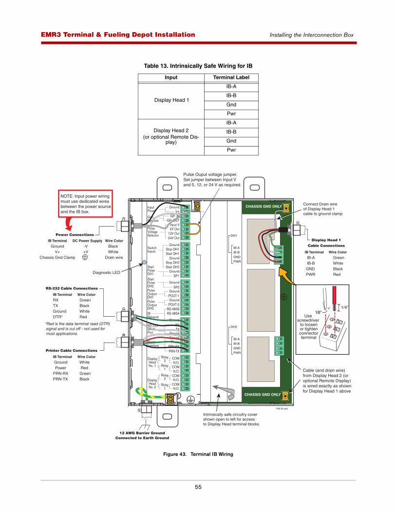
55
EMR3 - Truck InstallationsEMR3 Terminal & Fueling Depot Installation Installing the Interconnection Box
Figure 43. Terminal IB Wiring
Table 13. Intrinsically Safe Wiring for IB
Input Terminal Label
Display Head 1
IB-A
IB-B
Gnd
Pwr
Display Head 2(or optional Remote Dis-
play)
IB-A
IB-B
Gnd
Pwr
IB-AIB-BGNDPWR
DH1
IB-AIB-BGNDPWR
DH2
758-34.eps
IB Terminal
GroundV+
Chassis Gnd Clamp
Wire Color
Black WhiteDrain wire
DC Power Supply
-V +V
Power Connections
12 AWG Barrier GroundConnected to Earth Ground
IB Terminal
IB-A IB-B GND PWR
Wire Color
Green White Black Red
Display Head 1 Cable Connections
Diagnostic LED
Intrinsically safe circuitry covershown open to left for accessto Display Head terminal blocks
CHASSIS GND ONLY
CHASSIS GND ONLY
Connect Drain wireof Display Head 1cable to ground clamp
Pulse Ouput voltage jumper. Set jumper between Input V and 5, 12, or 24 V as required.
Cable (and drain wire)from Display Head 2 (or optional Remote Display)is wired exactly as shown for Display Head 1 above
IB Terminal
Ground PowerPRN-RXPRN-TX
Wire Color
White Red Green Black
Printer Cable Connections
IB Terminal
RX TXGroundDTR*
Wire Color
Green Black White Red
RS-232 Cable Connections
*Red is the data terminal read (DTR) signal and is cut off - not used for most applications.
NOTE: Input power wiring must use dedicated wires between the power sourceand the IB box.
1/4"1/8"
Use screwdriver
to loosenor tightenconnectorterminal
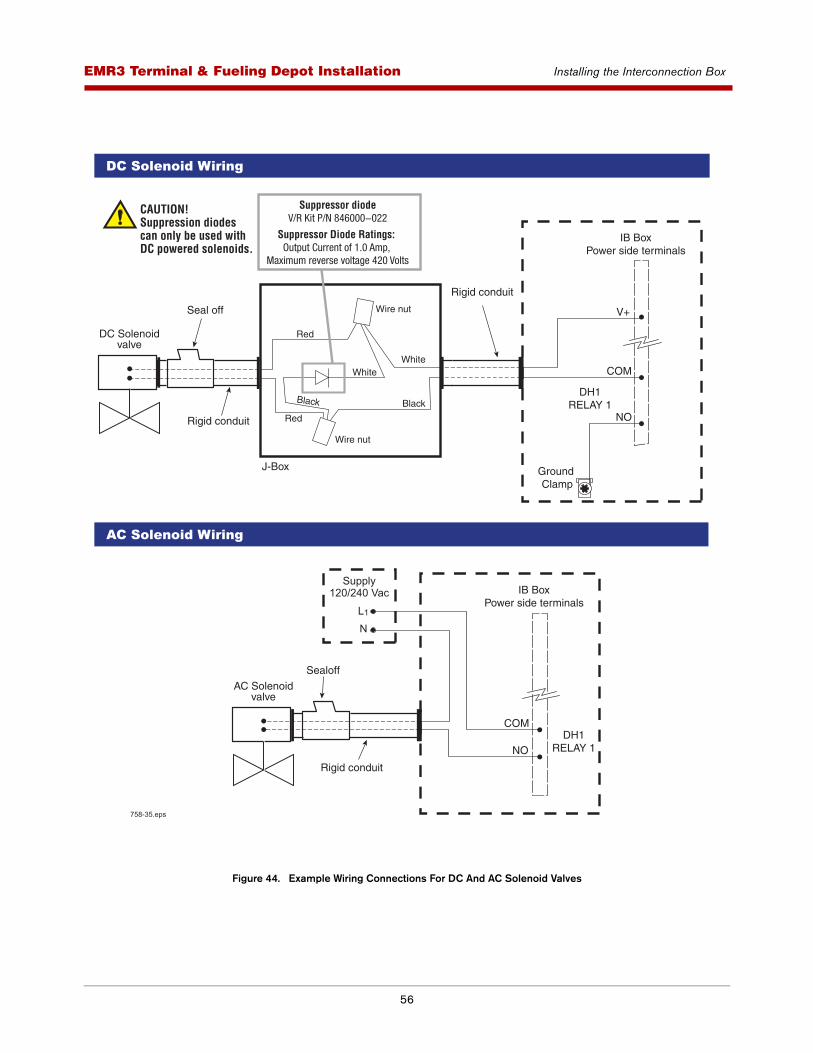
56
EMR3 - Truck InstallationsEMR3 Terminal & Fueling Depot Installation Installing the Interconnection Box
Figure 44. Example Wiring Connections For DC And AC Solenoid Valves
V+
DH1RELAY 1
IB BoxPower side terminals
DC Solenoidvalve
Rigid conduit
Seal off
NO
COM
J-Box Ground Clamp
Rigid conduit
LN
Supply120/240 Vac
1
DH1RELAY 1
IB BoxPower side terminals
AC Solenoidvalve
NO
COM
Rigid conduit
Sealoff
AC Solenoid Wiring
DC Solenoid Wiring
758-35.eps
Wire nut
Red
Red
BlackBlack
WhiteWhite
Wire nut
Suppressor diodeV/R Kit P/N 846000-022
Suppressor Diode Ratings: Output Current of 1.0 Amp,
Maximum reverse voltage 420 Volts
CAUTION! Suppression diodes can only be used with DC powered solenoids.
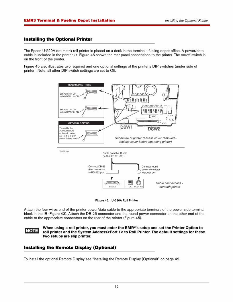
57
EMR3 - Truck InstallationsEMR3 Terminal & Fueling Depot Installation Installing the Optional Printer
Installing the Optional Printer
The Epson U-220A dot matrix roll printer is placed on a desk in the terminal - fueling depot office. A power/data cable is included in the printer kit. Figure 45 shows the rear panel connections to the printer. The on/off switch is on the front of the printer.
Figure 45 also illustrates two required and one optional settings of the printer’s DIP switches (under side of printer). Note: all other DIP switch settings are set to Off.
Figure 45. U-220A Roll Printer
Attach the four wires end of the printer power/data cable to the appropriate terminals of the power side terminal block in the IB (Figure 43). Attach the DB-25 connector and the round power connector on the other end of the cable to the appropriate connectors on the rear of the printer (Figure 45).
When using a roll printer, you must enter the EMR3’s setup and set the Printer Option to roll printer and the System Address>Port 1> to Roll Printer. The default settings for these two setups are slip printer.
Installing the Remote Display (Optional)
To install the optional Remote Display see “Installing the Remote Display (Optional)” on page 42.
RS-232 DK DC24-30V
Cable connections - beneath printer
Underside of printer (access cover removed -replace cover before operating printer)
Connect round power connector to power port
Connect DB-25 data connector to RS-232 port
Cable from the IB unit(V-R # 331791-001)
Set Pole 3 of DIPswitch DSW1 to ON
1 2
ON
3 4 5 6 7 8 9 10
Set Pole 1 of DIPswitch DSW2 to ON
1
ON
2 3 4 5 6 7 8 9 10
To enable the Autocut featureof the roll printer,set Pole 2 of DIPswitch DSW2 to ON
ON
2 3 4 5 6 7 8 9 10
REQUIRED SETTINGS
OPTIONAL SETTING
758-36.eps

58
EMR3 - Truck InstallationsEMR3 Terminal & Fueling Depot Installation Installing the Remote Pulser (Optional)
Installing the Remote Pulser (Optional)
To install the optional remote pulser see “Installing the Remote Pulser (Optional)” on page 46.
RS-232 Peripheral Equipment Requirements
Any peripheral equipment connected to an RS-232 serial port must meet the following criteria:
1. Peripheral equipment must be UL approved.
2. The equipment must have an EIA standard RS-232C or RS-232D communications protocol.
3. The equipment must NOT be installed over or in a hazardous location.
4. Maximum cable length is 50 feet (15.24 m).
5. Serial parameters- baud: 9600
- parity: none
- stop bits: 1
- data bits: 8
Note: for a list of serial commands, contact Veeder-Root directly.
Pulse Output for EMR3
RANGE OF VALUES ALLOWED FOR SET PULSES/VOL
• Minimum: 0.0
• Maximum: 99,999
HARDWARE SIGNALS
POUT-1 and POUT-2
• POUT-1 and POUT-2 are open collector outputs with an internal pull-up resistor (2.2K) tied to Input V. The output voltage can be set to either 5, 12, or 24 volts depending on the location of the pulse voltage selector jumper wire (see Figure 46).
• Typical duty cycle: variable length square wave
• Minimum period: 1.072 ms
• Maximum frequency: 933 Hz
• Minimum lag time: 460 ms (if within flow rates)
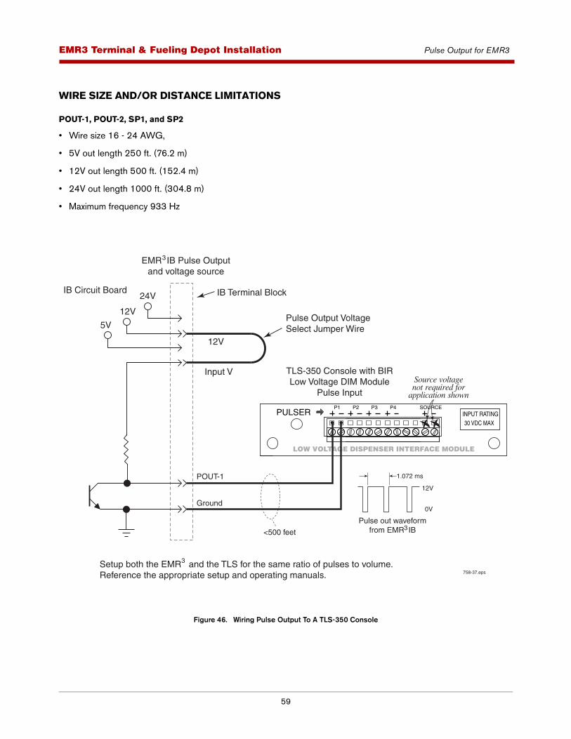
59
EMR3 - Truck InstallationsEMR3 Terminal & Fueling Depot Installation Pulse Output for EMR3
WIRE SIZE AND/OR DISTANCE LIMITATIONS
POUT-1, POUT-2, SP1, and SP2
• Wire size 16 - 24 AWG,
• 5V out length 250 ft. (76.2 m)
• 12V out length 500 ft. (152.4 m)
• 24V out length 1000 ft. (304.8 m)
• Maximum frequency 933 Hz
Figure 46. Wiring Pulse Output To A TLS-350 Console
12V
5V
24V
Input V
12V
IB Terminal Block
TLS-350 Console with BIRLow Voltage DIM Module
Pulse Input
IB Circuit Board
Pulse Output VoltageSelect Jumper Wire
POUT-1
Ground
<500 feet
758-37.eps
12V
1.072 ms
0V
Pulse out waveformfrom EMR IB3
P1
LOW VOLTAGE DISPENSER INTERFACE MODULE
PULSERP2 P3 P4 SOURCE
INPUT RATING30 VDC MAX
Source voltagenot required for
application shown
Setup both the EMR and the TLS for the same ratio of pulses to volume.Reference the appropriate setup and operating manuals.
3
EMR IB Pulse Outputand voltage source
3
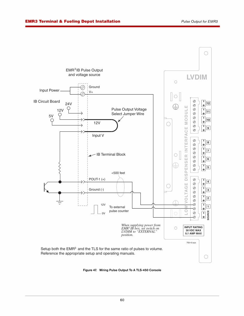
60
EMR3 - Truck InstallationsEMR3 Terminal & Fueling Depot Installation Pulse Output for EMR3
Figure 47. Wiring Pulse Output To A TLS-450 Console
12V
5V
24V
Input V
12V
IB Terminal Block
IB Circuit Board
Input Power
Pulse Output VoltageSelect Jumper Wire
POUT-1 (+)
Ground (-)
Ground
V+
758-43.eps
12V
0V
To externalpulse counter
When supplying power fromEMR IB box, set switch onLVDIM to “EXTERNAL” position.
3
Setup both the EMR and the TLS for the same ratio of pulses to volume.Reference the appropriate setup and operating manuals.
3
EMR IB Pulse Outputand voltage source
3
LVDIM
LO
W V
OL
TA
GE
DIS
PE
NS
ER
IN
TE
RF
AC
E M
OD
UL
E +-
+-
+-
+-
12
11
10
9
+-
+-
+-
+-
5
6
7
8
+-
+-
+-
+-
1
2
3
4
+-
SO
UR
CE
INPUT RATING30 VDC MAX0 1 AMP MAX
<500 feet
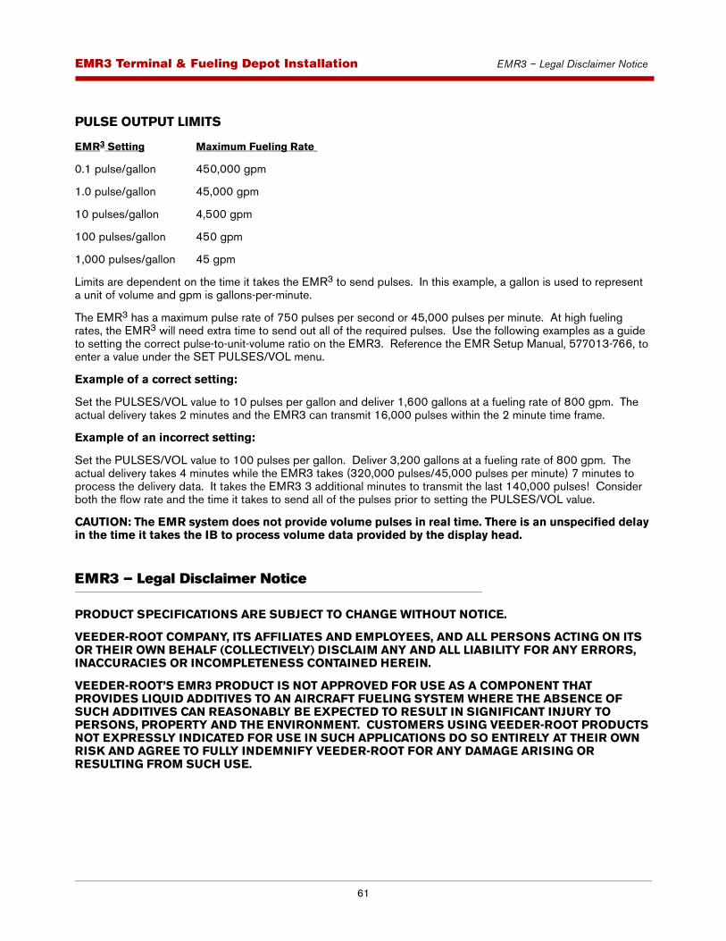
61
EMR3 - Truck InstallationsEMR3 Terminal & Fueling Depot Installation EMR3 – Legal Disclaimer Notice
PULSE OUTPUT LIMITS
EMR3 Setting Maximum Fueling Rate
0.1 pulse/gallon 450,000 gpm
1.0 pulse/gallon 45,000 gpm
10 pulses/gallon 4,500 gpm
100 pulses/gallon 450 gpm
1,000 pulses/gallon 45 gpm
Limits are dependent on the time it takes the EMR3 to send pulses. In this example, a gallon is used to represent a unit of volume and gpm is gallons-per-minute.
The EMR3 has a maximum pulse rate of 750 pulses per second or 45,000 pulses per minute. At high fueling rates, the EMR3 will need extra time to send out all of the required pulses. Use the following examples as a guide to setting the correct pulse-to-unit-volume ratio on the EMR3. Reference the EMR Setup Manual, 577013-766, to enter a value under the SET PULSES/VOL menu.
Example of a correct setting:
Set the PULSES/VOL value to 10 pulses per gallon and deliver 1,600 gallons at a fueling rate of 800 gpm. The actual delivery takes 2 minutes and the EMR3 can transmit 16,000 pulses within the 2 minute time frame.
Example of an incorrect setting:
Set the PULSES/VOL value to 100 pulses per gallon. Deliver 3,200 gallons at a fueling rate of 800 gpm. The actual delivery takes 4 minutes while the EMR3 takes (320,000 pulses/45,000 pulses per minute) 7 minutes to process the delivery data. It takes the EMR3 3 additional minutes to transmit the last 140,000 pulses! Consider both the flow rate and the time it takes to send all of the pulses prior to setting the PULSES/VOL value.
CAUTION: The EMR system does not provide volume pulses in real time. There is an unspecified delay in the time it takes the IB to process volume data provided by the display head.
EMR3 – Legal Disclaimer Notice
PRODUCT SPECIFICATIONS ARE SUBJECT TO CHANGE WITHOUT NOTICE.
VEEDER-ROOT COMPANY, ITS AFFILIATES AND EMPLOYEES, AND ALL PERSONS ACTING ON ITS OR THEIR OWN BEHALF (COLLECTIVELY) DISCLAIM ANY AND ALL LIABILITY FOR ANY ERRORS, INACCURACIES OR INCOMPLETENESS CONTAINED HEREIN.
VEEDER-ROOT’S EMR3 PRODUCT IS NOT APPROVED FOR USE AS A COMPONENT THAT PROVIDES LIQUID ADDITIVES TO AN AIRCRAFT FUELING SYSTEM WHERE THE ABSENCE OF SUCH ADDITIVES CAN REASONABLY BE EXPECTED TO RESULT IN SIGNIFICANT INJURY TO PERSONS, PROPERTY AND THE ENVIRONMENT. CUSTOMERS USING VEEDER-ROOT PRODUCTS NOT EXPRESSLY INDICATED FOR USE IN SUCH APPLICATIONS DO SO ENTIRELY AT THEIR OWN RISK AND AGREE TO FULLY INDEMNIFY VEEDER-ROOT FOR ANY DAMAGE ARISING OR RESULTING FROM SUCH USE.
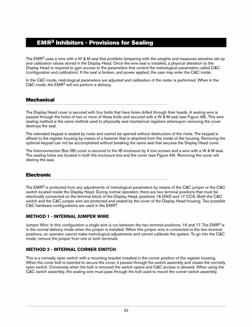
62
EMR3 Inhibitors - Provisions for Sealing
The EMR3 uses a wire with a W & M seal that prohibits tampering with the weights and measures sensitive set-up and calibration values stored in the Display Head. Once the wire seal is installed, a physical alteration to the Display Head is required to gain access to the parameters that control the metrological parameters called C&C (configuration and calibration). If the seal is broken, and power applied, the user may enter the C&C mode.
In the C&C mode, metrological parameters are adjusted and calibration of the meter is performed. When in the C&C mode, the EMR3 will not perform a delivery.
Mechanical
The Display Head cover is secured with four bolts that have holes drilled through their heads. A sealing wire is passed through the holes of two or more of these bolts and secured with a W & M seal (see Figure 48). This wire sealing method is the same method used to physically seal mechanical registers whereupon removing the cover destroys the seal.
The extended keypad is sealed by rivets and cannot be opened without destruction of the rivets. The keypad is affixed to the register housing by means of a fastener that is attached from the inside of the housing. Removing the optional keypad can not be accomplished without breaking the same seal that secures the Display Head cover.
The Interconnection Box (IB) cover is secured to the IB enclosure by 4 torx screws and a wire with a W & M seal. The sealing holes are located in both the enclosure box and the cover (see Figure 49). Removing the cover will destroy the seal.
Electronic
The EMR3 is protected from any adjustments of metrological parameters by means of the C&C jumper or the C&C switch located inside the Display Head. During normal operation, there are two terminal positions that must be electrically connected on the terminal block of the Display Head, positions 16 GND and 17 CCS. Both the C&C switch and the C&C jumper wire are protected and sealed by the cover of the Display Head housing. Two possible C&C hardware configurations are used in the EMR3.
METHOD 1 - INTERNAL JUMPER WIRE
Jumper Wire: In this configuration a single wire is run between the two terminal positions, 16 and 17. The EMR3 is in the normal delivery mode when the jumper is installed. When this jumper wire is connected to the two terminal positions, an operator cannot make metrological adjustments and cannot calibrate the system. To go into the C&C mode, remove the jumper from one or both terminals.
METHOD 2 - INTERNAL CORNER SWITCH
This is a normally open switch with a mounting bracket installed in the corner position of the register housing. When the cover bolt is inserted to secure the cover, it passes through the switch assembly and closes the normally open switch. Conversely when the bolt is removed the switch opens and C&C access is allowed. When using the C&C switch assembly, the sealing wire must pass through the bolt used to mount the corner switch assembly.
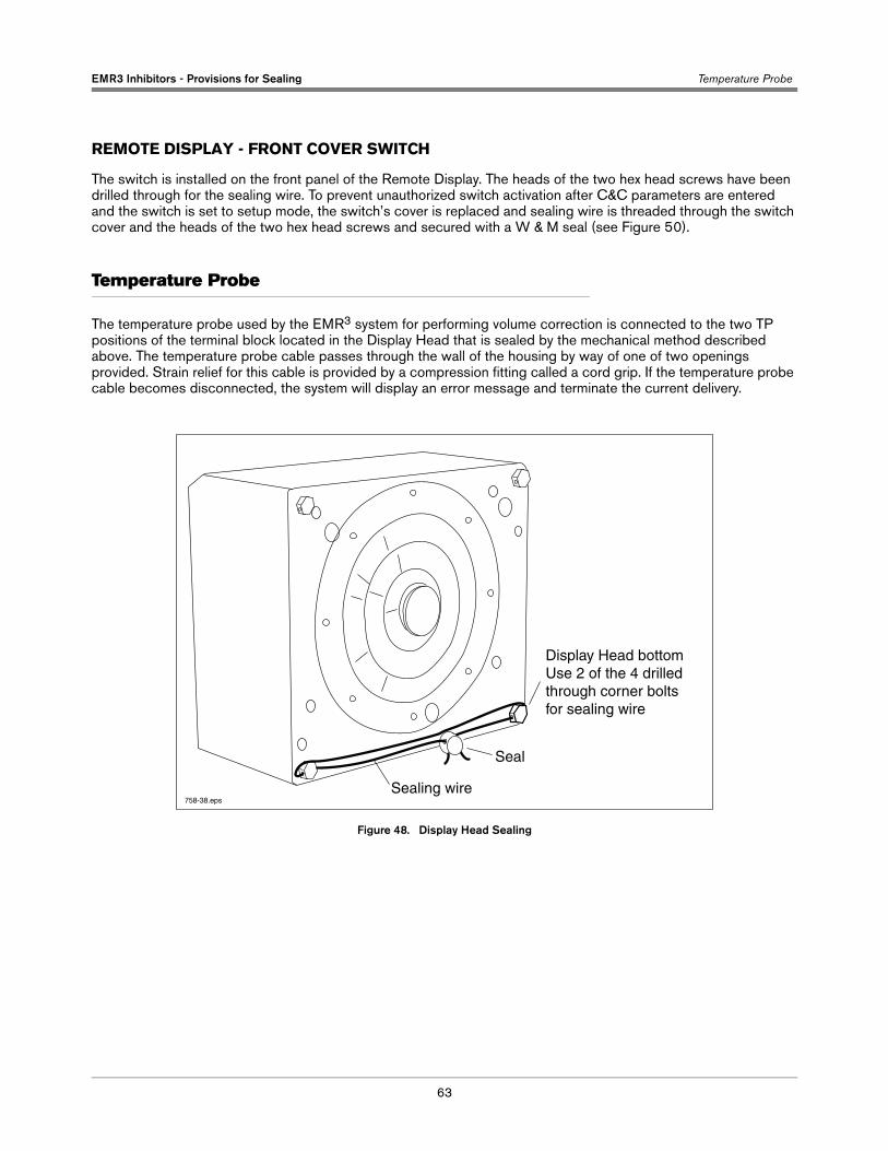
EMR3 Inhibitors - Provisions for Sealing Temperature Probe
63
REMOTE DISPLAY - FRONT COVER SWITCH
The switch is installed on the front panel of the Remote Display. The heads of the two hex head screws have been drilled through for the sealing wire. To prevent unauthorized switch activation after C&C parameters are entered and the switch is set to setup mode, the switch’s cover is replaced and sealing wire is threaded through the switch cover and the heads of the two hex head screws and secured with a W & M seal (see Figure 50).
Temperature Probe
The temperature probe used by the EMR3 system for performing volume correction is connected to the two TP positions of the terminal block located in the Display Head that is sealed by the mechanical method described above. The temperature probe cable passes through the wall of the housing by way of one of two openings provided. Strain relief for this cable is provided by a compression fitting called a cord grip. If the temperature probe cable becomes disconnected, the system will display an error message and terminate the current delivery.
Figure 48. Display Head Sealing
Sealing wire
Seal
Display Head bottom Use 2 of the 4 drilled through corner bolts for sealing wire
758-38.eps
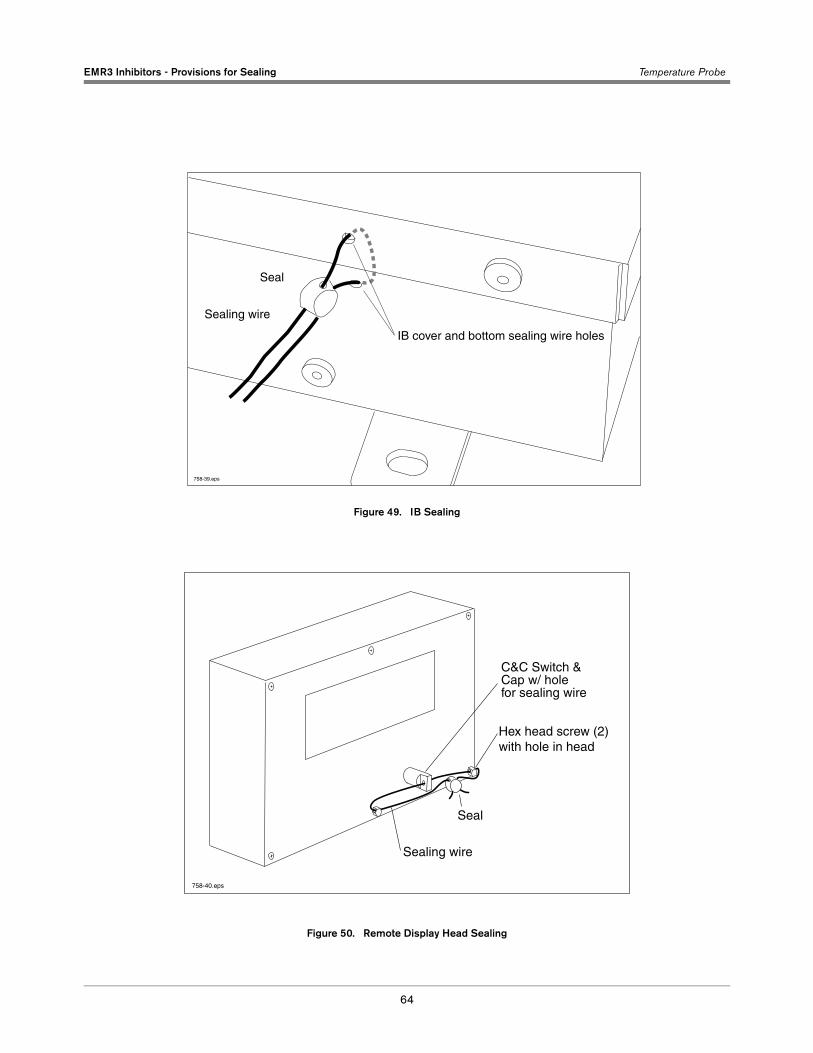
EMR3 Inhibitors - Provisions for Sealing Temperature Probe
64
Figure 49. IB Sealing
Figure 50. Remote Display Head Sealing
Sealing wire
Seal
IB cover and bottom sealing wire holes
758-39.eps
Hex head screw (2)with hole in head
Seal
Sealing wire
C&C Switch & Cap w/ holefor sealing wire
758-40.eps
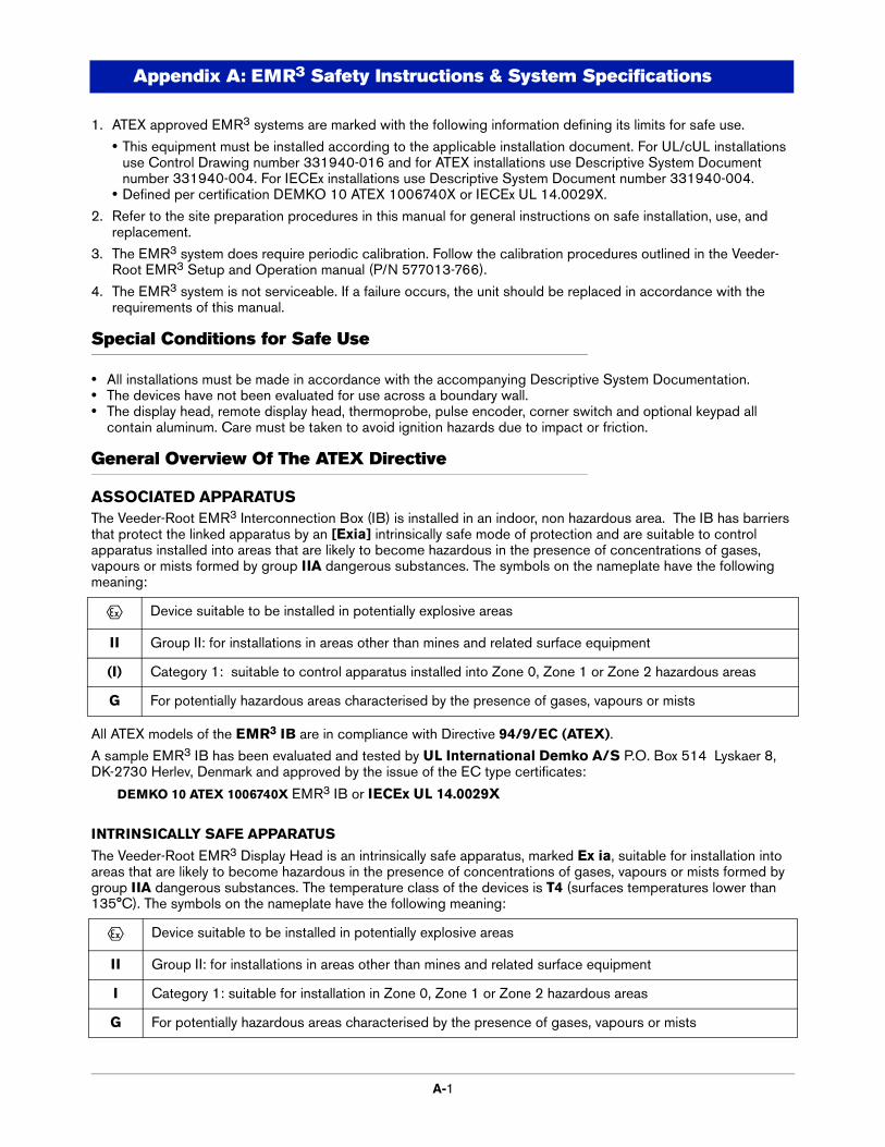
A-1
Appendix A: EMR3 Safety Instructions & System Specifications
1. ATEX approved EMR3 systems are marked with the following information defining its limits for safe use.
• This equipment must be installed according to the applicable installation document. For UL/cUL installations use Control Drawing number 331940-016 and for ATEX installations use Descriptive System Document number 331940-004. For IECEx installations use Descriptive System Document number 331940-004.
• Defined per certification DEMKO 10 ATEX 1006740X or IECEx UL 14.0029X.
2. Refer to the site preparation procedures in this manual for general instructions on safe installation, use, and replacement.
3. The EMR3 system does require periodic calibration. Follow the calibration procedures outlined in the Veeder-Root EMR3 Setup and Operation manual (P/N 577013-766).
4. The EMR3 system is not serviceable. If a failure occurs, the unit should be replaced in accordance with the requirements of this manual.
Special Conditions for Safe Use
• All installations must be made in accordance with the accompanying Descriptive System Documentation.• The devices have not been evaluated for use across a boundary wall.• The display head, remote display head, thermoprobe, pulse encoder, corner switch and optional keypad all
contain aluminum. Care must be taken to avoid ignition hazards due to impact or friction.
General Overview Of The ATEX Directive
ASSOCIATED APPARATUSThe Veeder-Root EMR3 Interconnection Box (IB) is installed in an indoor, non hazardous area. The IB has barriers that protect the linked apparatus by an [Exia] intrinsically safe mode of protection and are suitable to control apparatus installed into areas that are likely to become hazardous in the presence of concentrations of gases, vapours or mists formed by group IIA dangerous substances. The symbols on the nameplate have the following meaning:
All ATEX models of the EMR3 IB are in compliance with Directive 94/9/EC (ATEX).
A sample EMR3 IB has been evaluated and tested by UL International Demko A/S P.O. Box 514 Lyskaer 8, DK-2730 Herlev, Denmark and approved by the issue of the EC type certificates:
DEMKO 10 ATEX 1006740X EMR3 IB or IECEx UL 14.0029X
INTRINSICALLY SAFE APPARATUS
The Veeder-Root EMR3 Display Head is an intrinsically safe apparatus, marked Ex ia, suitable for installation into areas that are likely to become hazardous in the presence of concentrations of gases, vapours or mists formed by group IIA dangerous substances. The temperature class of the devices is T4 (surfaces temperatures lower than 135°C). The symbols on the nameplate have the following meaning:
e Device suitable to be installed in potentially explosive areas
II Group II: for installations in areas other than mines and related surface equipment
(I) Category 1: suitable to control apparatus installed into Zone 0, Zone 1 or Zone 2 hazardous areas
G For potentially hazardous areas characterised by the presence of gases, vapours or mists
e Device suitable to be installed in potentially explosive areas
II Group II: for installations in areas other than mines and related surface equipment
I Category 1: suitable for installation in Zone 0, Zone 1 or Zone 2 hazardous areas
G For potentially hazardous areas characterised by the presence of gases, vapours or mists
Appendix A: EMR3 Safety Instructions & System Specifications EMR3 System Specifications
A-2
All ATEX models of the EMR3 are in compliance with Directive 94/9/EC (ATEX).
A sample has been evaluated and tested by UL International Demko A/S P.O. Box 514 Lyskaer 8, DK-2730 Herlev, Denmark and approved by the issue of the EC type certificates:
DEMKO 10 ATEX 1006740X or IECEx UL 14.0029X
EMR3 Display Head
EMR3 Remote Pulser + Encoder
Symbol X used as suffix in all of the EC type test certificates listed above indicates the need for observing special conditions for safe use. Further information is provided in each respective EC type certificate under the paragraph, SPECIAL CONDITIONS FOR SAFE USE.
The manufacturers Quality System has been reviewed and is notified by SGS Baseefa, Staden Lane, Buxton, Derbyshire SK17 9RZ, United Kingdom authorizing the use of its ID 1180 in conjunction with the CE mark. The manufacturer is notified via SGS Baseefa QAN No. BASEEFA ATEX 1968. The CE mark may indicate compliance with other relevant EC directives. Consult the manufacturers EC Declarations of Conformity for details.
In addition to certified intrinsically safe apparatus, Veeder-Root also provides simple apparatus that comply with the requirements of EN 60079-11, Clause 5.7. These devices include; Thermoprobe, Emergency Stop Switch, Corner Switch and the Optional Keypad. Figures showing these devices may contain devices that are outside the scope of this ATEX Certificate.
EMR3 System Specifications
COMPONENT LOCATION
The EMR3 system should be located on a fuel delivery vehicle as shown in Figure 1 on page 1-5 or in a fueling depot as shown in Figure 38 on page 1-47.
The equipment is designed to operate safely under the following range of conditions:
• Altitude up to 2000m.
• Temperature range - see Table A-1.
• A maximum relative humidity of 95% RH (non-condensing) at temperatures shown in Table A-1.
• A supply voltage fluctuation not exceeding 28 Vdc.
• Pollution Degree Category 2, Installation Category II.
EMR3 IB units are not suitable for external locations and must be installed within the interior of buildings or the cab of the fuel deliver vehicle.
Ensure that the EMR3 IB is located where neither the unit itself nor its associated cabling will be damaged by doors, furniture, barrows, etc. - depot installs or nearby equipment - vehicle installs.
Consider the ease of routing wiring, ducting and cables to the EMR3 IB.
Check that the mounting surface material is strong enough to support the EMR3 IB.
If the unit requires cleaning, do not use any liquid materials (e.g. cleaning solvents). It is recommended that the unit be wiped with a clean dry cloth when necessary.
c1180 Equipment marking is compliant with requirements in the CE Marking Directive.
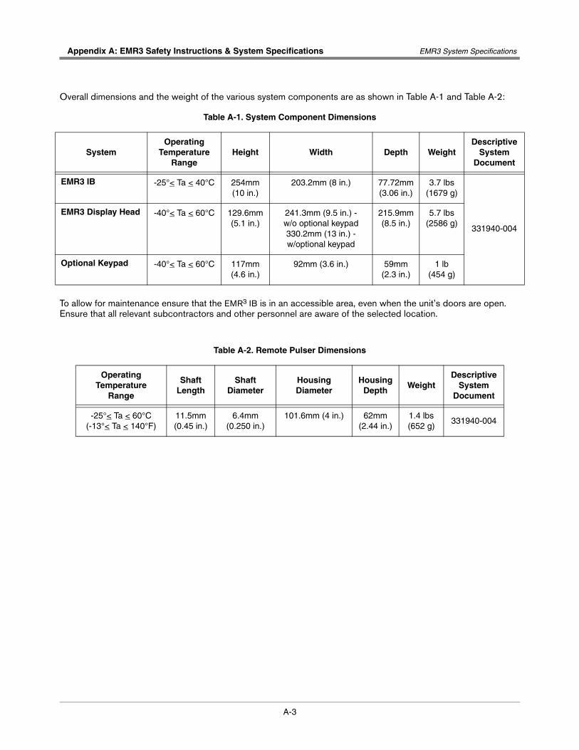
A-3
Appendix A: EMR3 Safety Instructions & System Specifications EMR3 System Specifications
Overall dimensions and the weight of the various system components are as shown in Table A-1 and Table A-2:
To allow for maintenance ensure that the EMR3 IB is in an accessible area, even when the unit’s doors are open. Ensure that all relevant subcontractors and other personnel are aware of the selected location.
Table A-1. System Component Dimensions
SystemOperating
Temperature Range
Height Width Depth WeightDescriptive
System Document
EMR3 IB -25°< Ta < 40°C 254mm (10 in.)
203.2mm (8 in.) 77.72mm (3.06 in.)
3.7 lbs(1679 g)
331940-004
EMR3 Display Head -40°< Ta < 60°C 129.6mm (5.1 in.)
241.3mm (9.5 in.) - w/o optional keypad330.2mm (13 in.) - w/optional keypad
215.9mm (8.5 in.)
5.7 lbs(2586 g)
Optional Keypad -40°< Ta < 60°C 117mm (4.6 in.)
92mm (3.6 in.) 59mm (2.3 in.)
1 lb(454 g)
Table A-2. Remote Pulser Dimensions
Operating Temperature
Range
Shaft Length
Shaft Diameter
Housing Diameter
HousingDepth
WeightDescriptive
System Document
-25°< Ta < 60°C(-13°< Ta < 140°F)
11.5mm (0.45 in.)
6.4mm (0.250 in.)
101.6mm (4 in.) 62mm (2.44 in.)
1.4 lbs(652 g)
331940-004
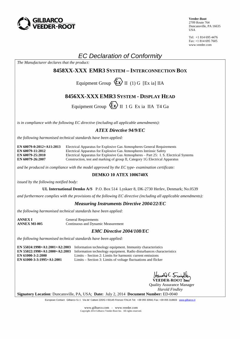
Veeder-Root 2709 Route 764 Duncansville, PA 16635 USA Tel: +1 814 695 4476 Fax: +1 814 695 7605 www.veeder.com
www.gilbarco.com - www.veeder.com Copyright 2014 Gilbarco Veeder-Root Inc. All rights reserved.
EC Declaration of Conformity The Manufacturer declares that the product:
8458XX-XXX EMR3 SYSTEM – INTERCONNECTION BOX
Equipment Group II (1) G [Ex ia] IIA
8456XX-XXX EMR3 SYSTEM - DISPLAY HEAD
Equipment Group II 1 G Ex ia IIA T4 Ga
is in compliance with the following EC directive (including all applicable amendments):
ATEX Directive 94/9/EC the following harmonised technical standards have been applied: EN 60079-0:2012+A11:2013 Electrical Apparatus for Explosive Gas Atmospheres General Requirements EN 60079-11:2012 Electrical Apparatus for Explosive Gas Atmospheres Intrinsic Safety EN 60079-25:2010 Electrical Apparatus for Explosive Gas Atmospheres – Part 25: I. S. Electrical Systems EN 60079-26:2007 Construction, test and marking of group II, Category 1G Electrical Apparatus and be produced in compliance with the model approved by the EC type- examination certificate:
DEMKO 10 ATEX 1006740X
issued by the following notified body:
UL International Demko A/S P.O. Box 514 Lyskaer 8, DK-2730 Herlev, Denmark; No.0539
and furthermore complies with the provisions of the following EC directive (including all applicable amendments):
Measuring Instruments Directive 2004/22/EC the following harmonised technical standards have been applied: ANNEX I General Requirements ANNEX MI-005 Continuous and Dynamic Measurement
EMC Directive 2004/108/EC the following harmonised technical standards have been applied: EN 55024:1998+A1:2001+A2:2003 Information technology equipment. Immunity characteristics EN 55022:1998+A1:2000+A2:2003 Information technology equipment. Radio disturbances characteristics EN 61000-3-2:2000 Limits – Section 2: Limits for harmonic current emissions EN 61000-3-3:1995+A1:2001 Limits – Section 3: Limits of voltage fluctuations and flicker
Quality Assurance Manager
Harold Findley Signatory Location: Duncansville, PA, USA; Date: July 2, 2014 Document Number: ED-0040
European Contact: Gilbarco S.r.l. Via de' Cattani 220/G I-50145 Firenze ITALIA Tel: +39 055 30941 Fax: +39 055 318603 www.gilbarco.it
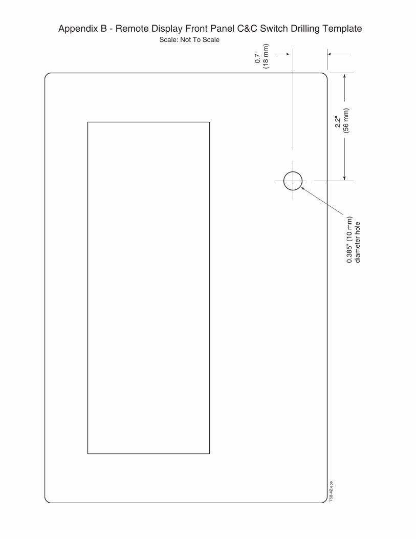
758-
42.e
ps
0.38
5" (
10 m
m)
diam
eter
hol
e
0.7"
(1
8 m
m)
2.2"
(5
6 m
m)
Appendix B - Remote Display Front Panel C&C Switch Drilling TemplateScale: Not To Scale
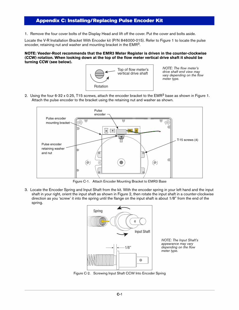
C-1
Appendix C: Installing/Replacing Pulse Encoder Kit
1. Remove the four cover bolts of the Display Head and lift off the cover. Put the cover and bolts aside.
Locate the V-R Installation Bracket With Encoder kit (P/N 846000-015). Refer to Figure 1 to locate the pulse encoder, retaining nut and washer and mounting bracket in the EMR3.
NOTE: Veeder-Root recommends that the EMR3 Meter Register is driven in the counter-clockwise (CCW) rotation. When looking down at the top of the flow meter vertical drive shaft it should be turning CCW (see below).
2. Using the four 6-32 x 0.25, T15 screws, attach the encoder bracket to the EMR3 base as shown in Figure 1. Attach the pulse encoder to the bracket using the retaining nut and washer as shown.
Figure C-1. Attach Encoder Mounting Bracket to EMR3 Base
3. Locate the Encoder Spring and Input Shaft from the kit. With the encoder spring in your left hand and the input shaft in your right, orient the input shaft as shown in Figure 2, then rotate the input shaft in a counter-clockwise direction as you ‘screw’ it into the spring until the flange on the input shaft is about 1/8” from the end of the spring.
Figure C-2. Screwing Input Shaft CCW Into Encoder Spring
Top of flow meter’svertical drive shaft
Rotation
Pulse encoderretaining washerand nut
Pulseencoder
Pulse encoder mounting bracket
T-15 screws (4)
Input Shaft
Spring
1/8”
NOTE: The Input Shaft’s appearance may vary depending on the flow meter type.
NOTE: The flow meter’s drive shaft end view may vary depending on the flow meter type.
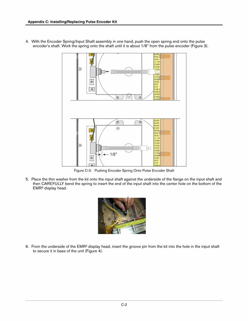
Appendix C: Installing/Replacing Pulse Encoder Kit
C-2
4. With the Encoder Spring/Input Shaft assembly in one hand, push the open spring end onto the pulse encoder’s shaft. Work the spring onto the shaft until it is about 1/8” from the pulse encoder (Figure 3).
Figure C-3. Pushing Encoder Spring Onto Pulse Encoder Shaft
5. Place the thin washer from the kit onto the input shaft against the underside of the flange on the input shaft and then CAREFULLY bend the spring to insert the end of the input shaft into the center hole on the bottom of the EMR³ display head.
6. From the underside of the EMR³ display head, insert the groove pin from the kit into the hole in the input shaft to secure it in base of the unit (Figure 4).
08 KP809 AS-10 AS+11 +5V12 GND13 CHB14 CHA15 PTR16 GND17 CCS18 GND19 ESS20 TP21 TP22 MF-A23 MF-B24 PWR25 GND26 IB-B27 IB-A
1/8”
01 CGND02 KP203 KP304 KP405 KP506 KP607 KP708 KP809 AS-10 AS+11 +5V12 GND13 CHB14 CHA15 PTR16 GND17 CCS18 GND19 ESS20 TP21 TP22 MF-A
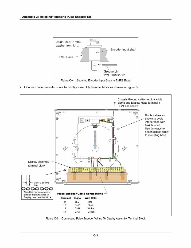
C-3
Appendix C: Installing/Replacing Pulse Encoder Kit
Figure C-4. Securing Encoder Input Shaft In EMR3 Base
7. Connect pulse encoder wires to display assembly terminal block as shown in Figure 5.
Figure C-5. Connecting Pulse Encoder Wiring To Display Assembly Terminal Block
EMR Base
0.005" (0.127 mm)washer from kit
Encoder input shaft
Groove pinP/N 510162-001
Terminal
11 12 13 14
Wire Color
Red Black White Green
Signal
+5V GND CHB CHA
Pulse Encoder Cable Connections
Display assemblyterminal block
Chassis Ground - attached to saddle clamp and Display Head terminal 1 CGND as shown
Route cables as shown to avoidinterference withflexible shaft. Use tie wraps to attach cables firmlyto mounting base
01 CGND02 KP203 KP304 KP405 KP506 KP607 KP708 KP809 AS-10 AS+11 +
5V12 GND13 CHB14 CHA15 PTR16 GND17 CCS18 GND19 ESS20 TP21 TP22 M
F-A23 M
F-B24 PW
R25 GND26 IB-B27 IB-A
9/64" (3.58 mm) max
Note Maximum screwdriver size for attaching wires to Display Head terminal block

For technical support, sales orother assistance, please visit:
www.veeder.com