Embed Size (px)
Citation preview
Workshop proceedings
11th International Conference on Model Driven Engineering Languages and Systems Toulouse, France September 28 – October 3, 2008
Empirical Studies of Model-Driven Engineering (ESMDE'08) September 29

i
Preface
It is often difficult to rigorously evaluate Model-Driven Engineering (MDE) technologies. Performing empirical studies require skills, experience and tacit knowledge that are in many ways very different from the “core” MDE research. Furthermore, empirical studies often entail large investments in terms of human resources, time and money. Nevertheless, evaluations of MDE technologies are needed in order to demonstrate the soundness, applicability, and cost effectiveness of proposed technologies in various development contexts. The aim of this workshop is to exemplify and discuss ways in which proposed model-driven engineering (MDE) technologies should be evaluated, with a specific emphasis on how to plan, conduct, analyze and report the results of empirical studies. The workshop will have focus on the challenges of empirical studies involving human users, since MDE technologies are typically expected to be used by software engineers to improve various quality aspects of software systems and the productivity of software development. More detailed topics include: What are the main obstacles and potential remedies when performing empirical studies of MDE? What are the main threats to validity of empirical studies of MDE, and how should they be dealt with? For example, since MDE often represent new and complex technology, the selection and training of human subjects who participate in empirical studies often become critical factors. What are the most important outcome variables of the costs and benefits of MDE? How can quality be measured in the context of MDE? And can we define an unambiguous set of (benchmark) outcome measures to facilitate meta-analyses across subjects, systems, tasks and technologies? The goal of the workshop is to pave the way for the development of a MDE-specific framework for empirical evaluation of MDE technologies, or at least provide a minimum standard for evaluation that published work in the MDE community should abide by. Erik Arisholm Lionel Briand Bente Anda

iii
Program committee
Colin Atkinson, University of Mannheim, Germany
Christian Bunse, International University, Germany
Michel Chaudron, Eindhoven University of Technology, Netherlands
Massimiliano Di Penta, University of Sannio, Italy
Robert B. France, Colorado State University, USA
Marcela Genero, University of Castilla-La Mancha, Spain
Marianne Huchard, University of Montpellier II, France
Ferhat Khendek, Concordia University, Canada
Yves Le Traon, IT/Telecom Bretagne, France
Tim Menzies, West Virginia University, USA
Alexander Pretschner, ETH Zurich, Switzerland
Per Runeson, Lund University, Sweden
Houari Sahraoui, University of Montreal, Canada
Miroslaw Staron, IT University of Göteborg, Sweden
v
Content Preface i Program committee iii On the Quantitative Assessment of Class Model Compositions: An Exploratory Study 1 Preparing Meta-Analysis of Metamodel Understandability 11 Empirical comparison of two class model normalization techniques Obstacles and questions 21 Assessing the Power of A Visual Notation – Preliminary Contemplations on Designing a Test – 31 Embedded System Construction – Evaluation of Model-Driven and Component-Based Development Approaches 41 Towards Quality-Driven Model Transformations: A Replication Study 51 Analyzing the Influence of Certain Factors on the Acceptance of a Model-based Measurement Procedure in Practice: An Empirical Study 61 Towards a generic framework for empirical studies of Model-Driven Engineering 71
On the Quantitative Assessment of Class Model Compositions: An Exploratory Study
Kleinner Oliveira1, Alessandro Garcia2, Jon Whittle2
1 Computer Science Department
Pontifical Catholic University of Rio de Janeiro Rio de Janeiro, RJ - Brazil
2 Computing Department Lancaster University – InfoLab 21
Lancaster - UK {alessandro,jon}@comp.lancs.ac.uk
Abstract. Model composition can be viewed in model-driven engineering as an operation where a set of activities should be performed to merge two input models into a single output model. The latter aggregates syntactical and semantic properties from the original models. However, given the growing heterogeneity of model composition strategies, it is particularly challenging for designers to objectively assess them given a particular problem at hand. The key problem is that there is a lack of canonical set of indicators to quantify harmful properties associated with the output models, such as composition conflicts and modularity anomalies. This paper presents an inquisitive study in order to capture an initial set of metrics for assessing and comparing model composition strategies in two case studies. We apply a number of metrics to quantify different conflict types and modularity properties arising at composite class models produced with override and merge-based strategies. We have observed that some of the quantitative indicators were effective to pinpoint when a model composition strategy is not properly chosen. In some cases, the output models exhibited non-obvious undesirable conflicts and anti-modularity factors.
Keywords: Model Composition, MDE, Metrics, Assessment.
1 Introduction
Given the central role that model composition plays in model-driven engineering nowadays, researchers are increasingly focusing on defining and improving alternative techniques for composing structural or behavioural models. Model composition can be defined by a composition operation, a special type of model transformation, that takes two models Ma and Mb as input models and combines their elements into an output model Mab. Several mechanisms have been proposed in order to put model composition into practice (e.g., see [2, 3, 4, 5, 6]), based on related work
MODELS`08 Workshop ESMDE
1
in many different domains, such as database integration [7], aspect-oriented modeling, model transformation , and merging of state charts.
However, not much attention has been paid to the quality assessment of such model composition techniques. Even worse, according to [5] there is very little experience that can be used to determine the worth of current approaches. Given the growing heterogeneity of model composition strategies [3], such as override and merge, it is intrinsically difficult to systematically quantify undesirable phenomena that arise in the output composite models, including abstract syntax conflicts and semantic clashes. It is particularly challenging for researchers or designers to objectively assess the output model and the composition strategy itself given the problem at hand.
In this paper we start to tackle such needs through an exploratory study (Section 2) on assessing composition strategies for class models. The goal is to inquisitively identify an initial set of indicators for the evaluation and comparison of alternative composition strategies. We have applied a metrics suite (Section 3) to quantify the conflicts rate and modularity properties arising in class model compositions based on merge and override. Our long-term goal is to define a comprehensive assessment framework intended to guide researchers and designers on the assessment of model composition techniques. In our study, we have detected that some of the used quantitative indicators were effective to determine when a model composition strategy is not properly chosen (Section 4). In certain cases, the output models exhibited non-obvious syntactic and semantic conflicts and a number of modularity anomalies not existing in the original input models. We also contrast the initial findings of our exploratory investigation with related work (Section 5). Finally, we present some concluding remarks (Section 6).
2 Experimental Procedures
This section describes the experimental procedures used in our exploratory study. Two case studies were performed in order to investigate possible problems associated with the use of composition strategies for class models. The first study comprises a set of real-life models for an Automated Highway Toll System. In this case, different members of a distributed software development team were in charge of modeling different use cases of the system. They would need to cope with model composition problems when bringing the use cases together.
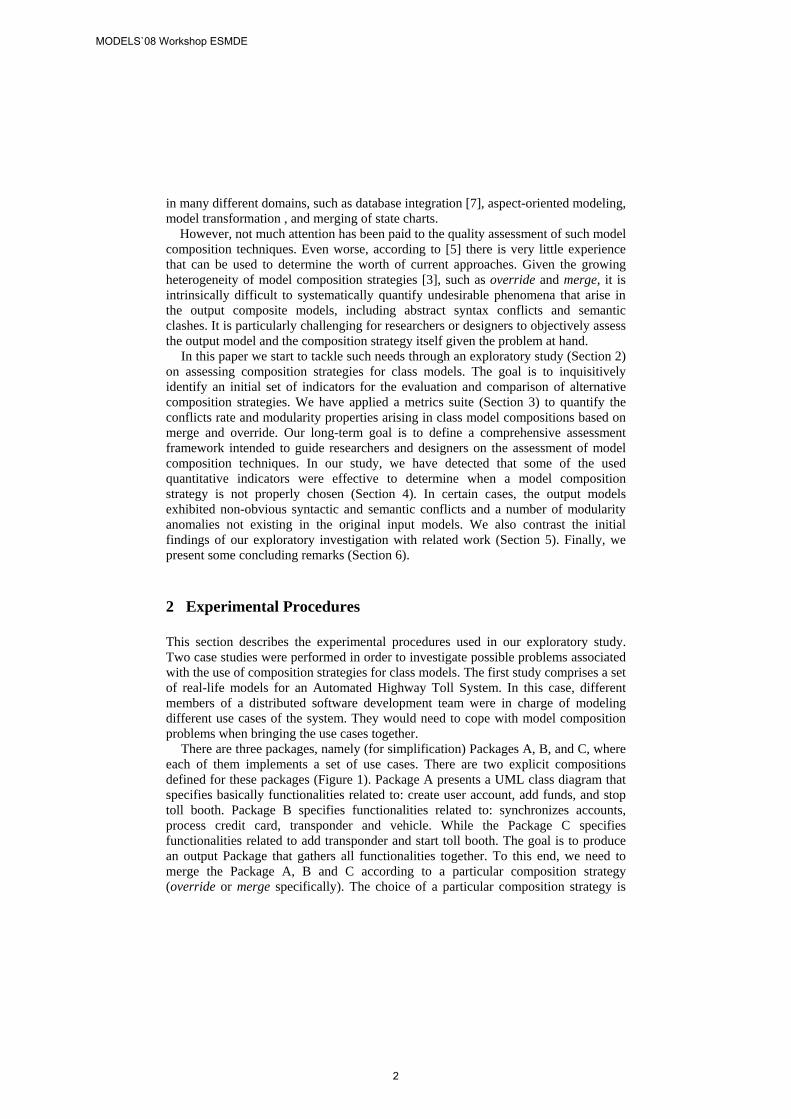
There are three packages, namely (for simplification) Packages A, B, and C, where each of them implements a set of use cases. There are two explicit compositions defined for these packages (Figure 1). Package A presents a UML class diagram that specifies basically functionalities related to: create user account, add funds, and stop toll booth. Package B specifies functionalities related to: synchronizes accounts, process credit card, transponder and vehicle. While the Package C specifies functionalities related to add transponder and start toll booth. The goal is to produce an output Package that gathers all functionalities together. To this end, we need to merge the Package A, B and C according to a particular composition strategy (override or merge specifically). The choice of a particular composition strategy is
MODELS`08 Workshop ESMDE
2
very important to produce sound output models while not introducing modularity impairments.
Figure 1. Example of composition of an automated highway toll system.
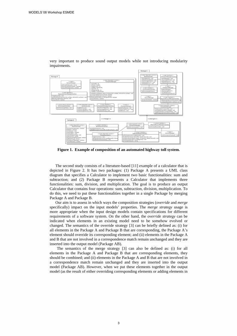
The second study consists of a literature-based [11] example of a calculator that is depicted in Figure 2. It has two packages: (1) Package A presents a UML class diagram that specifies a Calculator to implement two basic functionalities: sum and subtraction; and (2) Package B represents a Calculator that implements three functionalities: sum, division, and multiplication. The goal is to produce an output Calculator that contains four operations: sum, subtraction, division, multiplication. To do this, we need to put these functionalities together in a single Package by merging Package A and Package B.
Our aim is to assess in which ways the composition strategies (override and merge specifically) impact on the input models’ properties. The merge strategy usage is more appropriate when the input design models contain specifications for different requirements of a software system. On the other hand, the override strategy can be indicated when elements in an existing model need to be somehow evolved or changed. The semantics of the override strategy [3] can be briefly defined as: (i) for all elements in the Package A and Package B that are corresponding, the Package A’s element should override its corresponding element; and (ii) elements in the Package A and B that are not involved in a correspondence match remain unchanged and they are inserted into the output model (Package AB).
The semantics of the merge strategy [3] can also be defined as: (i) for all elements in the Package A and Package B that are corresponding elements, they should be combined; and (ii) elements in the Package A and B that are not involved in a correspondence match remain unchanged and they are inserted into the output model (Package AB). However, when we put these elements together in the output model (as the result of either overriding corresponding elements or adding elements in
MODELS`08 Workshop ESMDE
3
the Package AB directly) may result in some problems such as semantic clashes. We will propose a metrics suite to provide ways to assess how useful or harmful such composition relationships are following a specific composition strategy. The goal is to provide initial support for designers and researchers objectively analyze which composition strategy minimizes the conflicts rate while maximizing modularity benefits in the output model.
Figure 2. Example of composition of calculators
3 A Metrics Suite for Model Composition
This section presents the metrics suite defined for assessing the model compositions in our exploratory study. This framework guides the researchers for assessing and coping with difficulties of UML model composition assessment.
3.1 Quantifying Composition Conflicts Rate
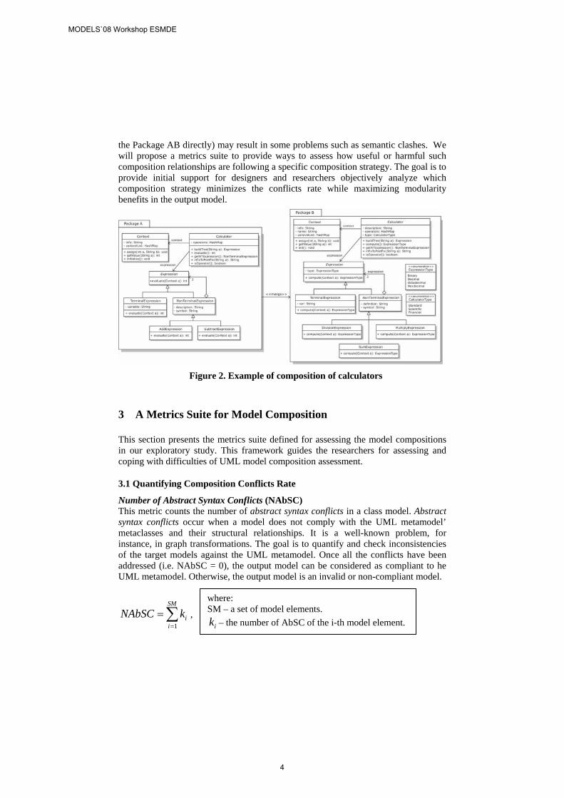
Number of Abstract Syntax Conflicts (NAbSC) This metric counts the number of abstract syntax conflicts in a class model. Abstract syntax conflicts occur when a model does not comply with the UML metamodel’ metaclasses and their structural relationships. It is a well-known problem, for instance, in graph transformations. The goal is to quantify and check inconsistencies of the target models against the UML metamodel. Once all the conflicts have been addressed (i.e. NAbSC = 0), the output model can be considered as compliant to he UML metamodel. Otherwise, the output model is an invalid or non-compliant model.
, ∑=
=SM
iikNAbSC
1
where: SM – a set of model elements.
– the number of AbSC of the i-th model element. ik
MODELS`08 Workshop ESMDE
4
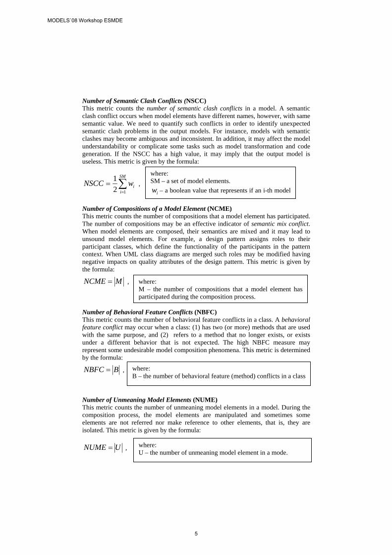
Number of Semantic Clash Conflicts (NSCC) This metric counts the number of semantic clash conflicts in a model. A semantic clash conflict occurs when model elements have different names, however, with same semantic value. We need to quantify such conflicts in order to identify unexpected semantic clash problems in the output models. For instance, models with semantic clashes may become ambiguous and inconsistent. In addition, it may affect the model understandability or complicate some tasks such as model transformation and code generation. If the NSCC has a high value, it may imply that the output model is useless. This metric is given by the formula:
∑=
=SM
iiwNSCC
121
, where: SM – a set of model elements.
iw – a boolean value that represents if an i-th model Number of Compositions of a Model Element (NCME) This metric counts the number of compositions that a model element has participated. The number of compositions may be an effective indicator of semantic mix conflict. When model elements are composed, their semantics are mixed and it may lead to unsound model elements. For example, a design pattern assigns roles to their participant classes, which define the functionality of the participants in the pattern context. When UML class diagrams are merged such roles may be modified having negative impacts on quality attributes of the design pattern. This metric is given by the formula:
MNCME = , where: M – the number of compositions that a model element has participated during the composition process.
Number of Behavioral Feature Conflicts (NBFC) This metric counts the number of behavioral feature conflicts in a class. A behavioral feature conflict may occur when a class: (1) has two (or more) methods that are used with the same purpose, and (2) refers to a method that no longer exists, or exists under a different behavior that is not expected. The high NBFC measure may represent some undesirable model composition phenomena. This metric is determined by the formula:
BNBFC = , where: B – the number of behavioral feature (method) conflicts in a class
Number of Unmeaning Model Elements (NUME) This metric counts the number of unmeaning model elements in a model. During the composition process, the model elements are manipulated and sometimes some elements are not referred nor make reference to other elements, that is, they are isolated. This metric is given by the formula:
where: U – the number of unmeaning model element in a mode.
UNUME = ,
MODELS`08 Workshop ESMDE
5
3.2 Quantifying Modularity Anomalies in Composite Models
We have also applied some classical metrics intended to measure some modularity-related characteristics of a class, such as coupling degree, number of attributes, and operations. These metrics are described in Table II. Due to space constraints, these metrics are briefly presented. In fact, most of these metrics (e.g. NATC and CBC) were originally defined by other authors and their definitions can be found in their respective publications [14, 17]. The goal of using these metrics is to assess how the composition process affects the output models regarding some design principles, such as low coupling, when we specify different composition strategies. In addition, in many cases, composition strategies can artificially lead to the introduction of design anomalies (“bad smells”), such as “Temporary Field”; this bad smell can be identified comparing the NATC of a class in the output model against the respective classes in the input models used for the composition.
Table I. The Class-level Modularity Metrics
Metric Description Number of Attributes in a Class (NATC)
Counts the number of attributes in a class.
Number of Operations in a Class (NOPC)
Counts the number of operation in a class.
Number of Associations between Classes (NASC)
Counts the number of associations per class; the new language produced from a model composition may not be consistent with the domain defined previously.
Coupling between Classes (CBC)
Counts the number of all dependencies of a class to other classes in the system.
Number of Subclasses of a Class (NSUBC)
Counts the number of children of a class.
Number of Superclasses of a Class (NSUPC)
Counts the parents of a class.
4. Results and Discussion
Quantitative assessment is an effective way to supply measures and evidence that may improve our understanding about model-driven engineering techniques, in our case, model composition. Although quantitative studies have some disadvantages, they are very useful because they boil a complex situation down to simple numbers that are easier to grasp and discuss. This section provides a general analysis and discussion of the data that have been collected from applying the set of defined metrics to model compositions derived in the two case studies (Section 2).
Graphics are used to represent the data gathered in the measurement process. The Y-axis presents the absolute values gathered by the metrics. Each pair of bars is attached to an integer value, which represents the measure. The X-axis specifies the metric itself. These graphics help analyzing how the composition of the input models affects (or not) the output model regarding a particular metric. These graphics support an analysis of how the change of composition strategy affect (or not) the output model. The results shown in the graphics were gathered according to the model point
MODELS`08 Workshop ESMDE
6
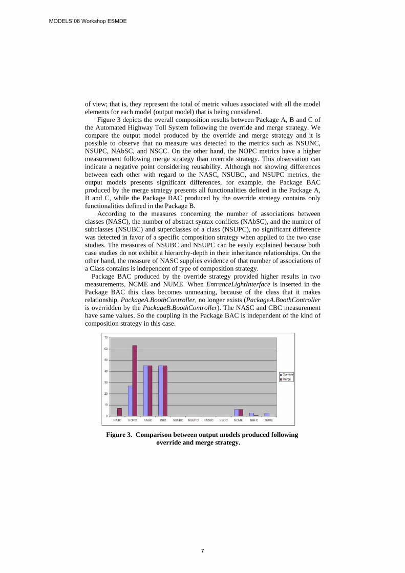
of view; that is, they represent the total of metric values associated with all the model elements for each model (output model) that is being considered.
Figure 3 depicts the overall composition results between Package A, B and C of the Automated Highway Toll System following the override and merge strategy. We compare the output model produced by the override and merge strategy and it is possible to observe that no measure was detected to the metrics such as NSUNC, NSUPC, NAbSC, and NSCC. On the other hand, the NOPC metrics have a higher measurement following merge strategy than override strategy. This observation can indicate a negative point considering reusability. Although not showing differences between each other with regard to the NASC, NSUBC, and NSUPC metrics, the output models presents significant differences, for example, the Package BAC produced by the merge strategy presents all functionalities defined in the Package A, B and C, while the Package BAC produced by the override strategy contains only functionalities defined in the Package B.
According to the measures concerning the number of associations between classes (NASC), the number of abstract syntax conflicts (NAbSC), and the number of subclasses (NSUBC) and superclasses of a class (NSUPC), no significant difference was detected in favor of a specific composition strategy when applied to the two case studies. The measures of NSUBC and NSUPC can be easily explained because both case studies do not exhibit a hierarchy-depth in their inheritance relationships. On the other hand, the measure of NASC supplies evidence of that number of associations of a Class contains is independent of type of composition strategy.
Package BAC produced by the override strategy provided higher results in two measurements, NCME and NUME. When EntranceLightInterface is inserted in the Package BAC this class becomes unmeaning, because of the class that it makes relationship, PackageA.BoothController, no longer exists (PackageA.BoothController is overridden by the PackageB.BoothController). The NASC and CBC measurement have same values. So the coupling in the Package BAC is independent of the kind of composition strategy in this case.
Figure 3. Comparison between output models produced following
override and merge strategy.
MODELS`08 Workshop ESMDE
7
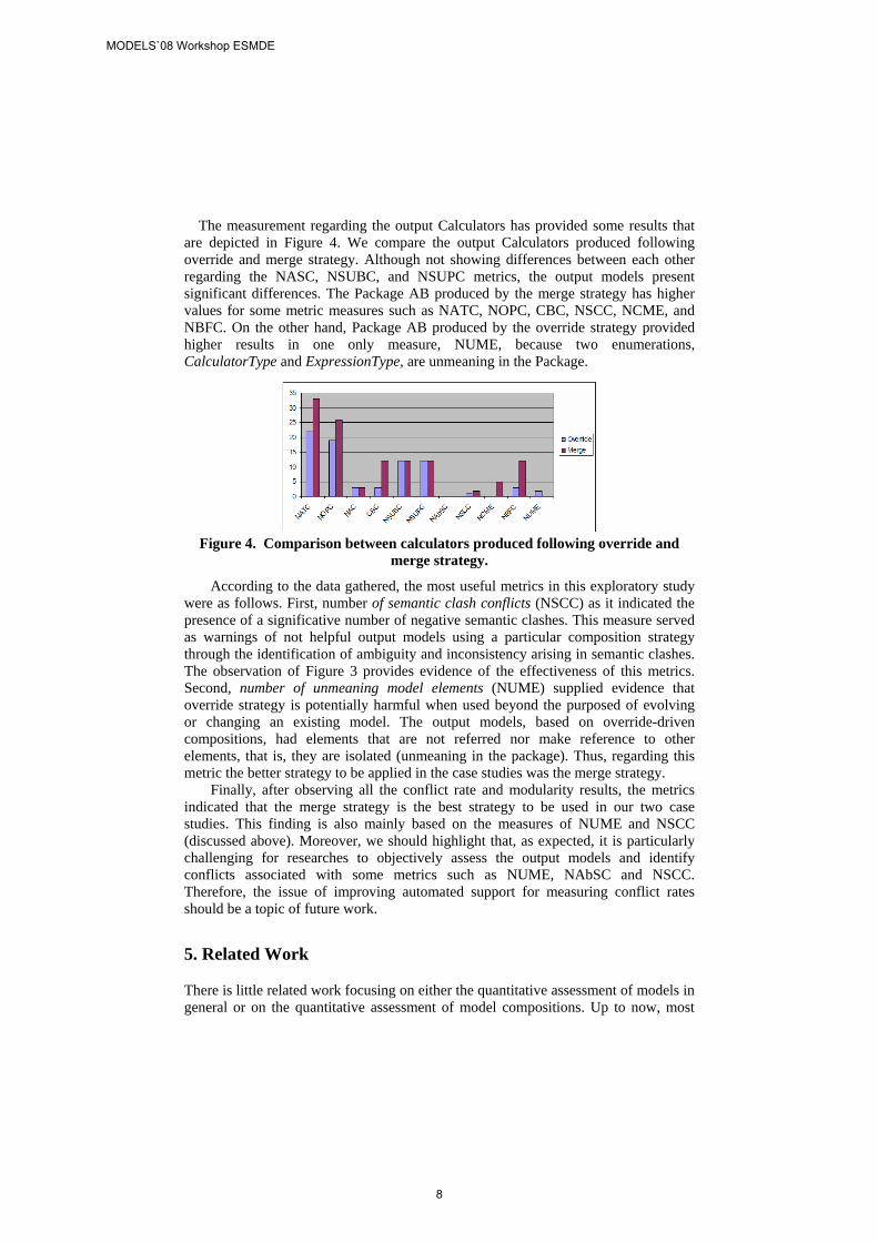
The measurement regarding the output Calculators has provided some results that are depicted in Figure 4. We compare the output Calculators produced following override and merge strategy. Although not showing differences between each other regarding the NASC, NSUBC, and NSUPC metrics, the output models present significant differences. The Package AB produced by the merge strategy has higher values for some metric measures such as NATC, NOPC, CBC, NSCC, NCME, and NBFC. On the other hand, Package AB produced by the override strategy provided higher results in one only measure, NUME, because two enumerations, CalculatorType and ExpressionType, are unmeaning in the Package.
Figure 4. Comparison between calculators produced following override and
merge strategy.
According to the data gathered, the most useful metrics in this exploratory study were as follows. First, number of semantic clash conflicts (NSCC) as it indicated the presence of a significative number of negative semantic clashes. This measure served as warnings of not helpful output models using a particular composition strategy through the identification of ambiguity and inconsistency arising in semantic clashes. The observation of Figure 3 provides evidence of the effectiveness of this metrics. Second, number of unmeaning model elements (NUME) supplied evidence that override strategy is potentially harmful when used beyond the purposed of evolving or changing an existing model. The output models, based on override-driven compositions, had elements that are not referred nor make reference to other elements, that is, they are isolated (unmeaning in the package). Thus, regarding this metric the better strategy to be applied in the case studies was the merge strategy.
Finally, after observing all the conflict rate and modularity results, the metrics indicated that the merge strategy is the best strategy to be used in our two case studies. This finding is also mainly based on the measures of NUME and NSCC (discussed above). Moreover, we should highlight that, as expected, it is particularly challenging for researches to objectively assess the output models and identify conflicts associated with some metrics such as NUME, NAbSC and NSCC. Therefore, the issue of improving automated support for measuring conflict rates should be a topic of future work.
5. Related Work
There is little related work focusing on either the quantitative assessment of models in general or on the quantitative assessment of model compositions. Up to now, most
MODELS`08 Workshop ESMDE
8
approaches involving model composition rest on subjective assessment criteria. Even worse, they lead to dependence on experts who have built up an arsenal of mentally-held indicators to evaluate the growing complexity of design models in general [5]. As a consequence, the truth is that modelers ultimately rely on feedback from experts to determine “how good” the input models and their compositions are. According to [5], the state of the practice in assessing model quality provides evidence that modeling is still in the craftsmanship era and when we assess model composition this problem is accentuated.
To the best of our knowledge, the need for assessing models during a model composition process neither have been pointed out nor even proposed by current model composition techniques [2, 3, 4, 8, 9]. For example, the UML built-in composition mechanism, namely package merge, does not define metrics or criteria to assess the merged UML models. Moreover, it has been found to be incomplete, ambiguous and inconsistent [6].
The lack of quantitative indicators for model compositions hinder our process of understanding better side effects peculiar to certain model composition strategies. Many different types of metrics have been developed during the past few decades for different UML models. These metrics have certainly helped designers analyze their UML models to some extent. However, as researchers’ focus has shifted to the activities related to model management (such as model composition, evolution and transformation), hence the shortcomings and limitation of UML model metrics have become more apparent. Some authors [1, 12, 13-18] have proposed a set of metrics that consider UML model’s properties. These works have shown that their measures satisfy some properties expected for good measures of design models. However, these metrics can not be employed to assess problems that may arise in a model composition process such as semantic clashes.
6. Concluding Remarks and Future Work
If models are seen as primary development and transformation artifacts in model-driven engineering, then software designers naturally become concerned with how their quality is evaluated. In order to be considered for use in mainstream software development, model composition techniques should be supplemented with quality criteria and indicators. These elements are fundamental for developing and analyzing composition processes and output models. We presented an exploratory study and an initial metrics suite for assessing class model compositions generated by a selected set of model composition strategies. Such metrics are applied to output models and some analysis are performed according to the data gathered.
Our initial evaluation has demonstrated the feasibility of our candidate set of metrics for quantifying modularity properties and conflict rates in composition processes. Obviously, more investigations on its applicability to large UML model compositions are required. Further empirical evaluations are indeed fundamental to validate our quantitative indicators in real-world design settings involving UML model compositions. Thus, future work will concentrate on designing and carrying out a family of empirical studies to assess, for example, compositions of the most popular OMG’s UML profiles in realistic scenarios. Finally, we should point out that
MODELS`08 Workshop ESMDE
9

model composition assessment is in initial stage and there is very little experience that can be used to determine the feasibility of current approaches. Moreover, its empirical-driven improvement, supported by a comprehensive set of well-validated metrics suite, is absolutely necessary to the evolution of model-driven engineering field. This work represents one of the first stepping stones towards this end.
References
1. J. Aranda, N. Ernst, J. Horkoff, and S. Easterbrook. A Framework for Empirical Evaluation of Model Comprehensibility. In International Workshop on Modeling in Software Engineering (MiSE), pp. 20-26, May, 2007.
2. G. Brunet, M. Chechik, S. Easterbrook, S. Nejati, N. Niu, and M. Sabetzadeh. A Manifesto for Model Merging. In International Workshop on Global Integrated Model Management (GaMMa’06), pages 5–12, Shanghai, China, May 2006. ACM Press.
3 S. Clarke and R. Walker. Composition Patterns: an Approach to Designing Reusable Aspects. 23rd Intl. Conf. on Software Engineering, pp. 5–14, Toronto, Canada, 2001.
4 T. Cotternier, A. van den Berg, and T. Elrad. Modeling Aspect-Oriented Composition. In 7th International Workshop n Aspect-Oriented Modeling co-located with (MODELS’ 05), Montego Bay, Jamaica, October 2005.
5 R. France and B. Rumpe. Model-Driven Development of Complex Software: A Research Roadmap. In Future of Software Engineering (FOSE’07) co-located with ICSE’07, pages 37–54, Minnesota, EUA, May 2007.
6 OMG, Unified Modeling Language: Infrastructure version 2.1, Object Management Group, February 2007.
7 E. Rahm and P. Bernstein. A Survey of Approaches to Automatic Schema Matching. VLDB Journal: Very Large Data Bases, 10(4):334–350, 2001.
8 R. Reddy, R. France, S. Ghosh, F. Fleurey, and B. Baudry. Model Composition – a Signature-Based Approach. In Aspect Oriented Modeling (AOM) Workshop, Montego Bay, Jamaica, October 2005.
9 Y. Reddy, R. France, G. Straw, N. M. J. Bieman, E. Song, and G. Georg. Directives for Composing Aspect-Oriented Design Class Models. Transactions of Aspect-Oriented Software Development, 1(1):75–105, 2006.
10 B. Selic. The Pragmatics of Model-Driven Development. IEEE Software, 20(5):19–25, 2003.
11. Gamma, E. et al. Design Patterns: Elements of Reusable Object-Oriented Software. Addison-Wesley, Reading, 1995.
12. Shyam R. Chidamber and Chris F. Kemerer. A metrics suite for object oriented design. IEEE Transactions on Software Engineering, 20(6):476–493, June 1994
13. A. Baroni, Quantitative assessment of UML dynamic models, SIGSOFT Software Eng. Notes, vol. 30, no. 5, pp. 366-369, 2005.
14. Baroni, A.L., Abreu, F.B. and Guerreiro, P. The State-of-the Art of UML Design Metrics. Technical Report, Universidade Nova de Lisboa, Monte da Caparica, 2005.
15. Shyam R. Chidamber and Chris F. Kemerer. A metrics suite for object oriented design. IEEE Transactions on Software Engineering, 20(6):476–493, June 1994
16. A. Baroni, Quantitative assessment of UML dynamic models, SIGSOFT Software Eng. Notes, vol. 30, no. 5, pp. 366-369, 2005.
17. A. Baroni, F. Abreu, and P. Guerreiro. The State-of-the Art of UML Design Metrics. Technical Report, Universidade Nova de Lisboa, Monte da Caparica, 2005.
18. M. Genero, M. Piattini-Velthuis, J. Lemus, and L. Reynoso Metrics for UML Models, UPGRADE, vol. 5, number 2, April, 2002.
MODELS`08 Workshop ESMDE
10
Preparing Meta-Analysis of Metamodel Understandability
Susanne Patig1
1 University of Bern, IWI, Engehaldenstrasse 8, CH-3012 Bern, Switzerland [email protected]
Abstract. Metamodels are designed to be used by machines and humans. For human users, the understandability of the metamodel is important. Experimen-tal investigations of understandability in computer science have led to conflict-ing results. To resolve such conflicts and gain insights into the nature of some phenomenon beyond singular experiments, meta-analysis can be applied, i.e., the statistical analysis of results obtained by other (primary) empirical studies. This paper shows the current obstacles for a meta-analysis of metamodel under-standability: They consist in the heterogeneity of the individual experiments and deficient reporting. The paper provides a framework to increase the comparability of experiments on understandability. Such comparability enables future meta-analysis.
Keywords: Understandability, Metamodels, Experimental Research
1 Motivation
Designing and modifying metamodels are major topics of model-driven development. Metamodels must be understandable for both machine and human users. Following a definition of language understandability in cognitive psychology [1], the understand-ability of a metamodel means the effort required to read and correctly interpret its constructs and their connections. Understandability is a prerequisite both for reading artifacts (like documents or source code) that have been created by a applying a metamodel (comprehension) and for creating such artifacts (specification).
The ‘understandability’ of a metamodel for a machine shows up in error-free com-pilation. For human users, metamodel understandability must be empirically inves-tigated, usually by controlled experiments. The results of such experiments are con-flicting (see Section 3).
Conflicting empirical results can be statistically evaluated by meta-analysis (see Section 2). Meta-analysis could increase our knowledge about the nature of under-standability – also to facilitate future metamodel design or modification. But, Section 3 shows that meta-analysis on metamodel understandability is currently hindered by (1) the heterogeneity of the conducted experiments and (2) insufficient reporting of the experimental results. This paper provides a framework to achieve comparability of experiments on metamodel understandability (see Section 4), which is a prerequisite for meta-analysis. Appropriate reporting guidelines exist (e.g., [16], [19]).
MODELS`08 Workshop ESMDE
11
2 Meta-Analysis
Meta-Analysis is the statistical evaluation of numerical results that have been obtained by other (primary) studies [25], [13]. Hence, it is a kind of secondary research that aims at (1) finding evidence for some investigated phenomenon beyond individual studies (by calculating general descriptive statistics), (2) explaining conflicting results (by discovering new influencing variables), and (3) removing the bias potentially contained in ‘normal’ literature reviews of empirical studies [27].
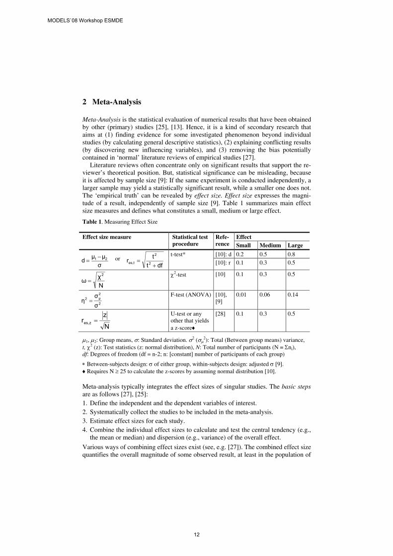
Literature reviews often concentrate only on significant results that support the re-viewer’s theoretical position. But, statistical significance can be misleading, because it is affected by sample size [9]: If the same experiment is conducted independently, a larger sample may yield a statistically significant result, while a smaller one does not. The ‘empirical truth’ can be revealed by effect size. Effect size expresses the magni-tude of a result, independently of sample size [9]. Table 1 summarizes main effect size measures and defines what constitutes a small, medium or large effect.
Table 1. Measuring Effect Size
Effect Effect size measure Statistical test procedure
Refe-rence Small Medium Large
[10]: d 0.2 0.5 0.8
σμμd 21 −= or
dfttr 2
2
t,es +=
t-test*
[10]: r 0.1 0.3 0.5
Nχω
2
= χ2-test [10] 0.1 0.3 0.5
2
2μ2
σσ
η = F-test (ANOVA) [10],
[9] 0.01 0.06 0.14
N
zr z,es =
U-test or any other that yields a z-score♦
[28] 0.1 0.3 0.5
μ1, μ2: Group means, σ: Standard deviation. σ2 (σμ2): Total (Between group means) variance,
t, χ2 (z): Test statistics (z: normal distribution), N: Total number of participants (N = Σni), df: Degrees of freedom (df = n-2; n: [constant] number of participants of each group)
∗ Between-subjects design: σ of either group, within-subjects design: adjusted σ [9]. ♦Requires N ≥ 25 to calculate the z-scores by assuming normal distribution [10].
Meta-analysis typically integrates the effect sizes of singular studies. The basic steps are as follows [27], [25]: 1. Define the independent and the dependent variables of interest. 2. Systematically collect the studies to be included in the meta-analysis. 3. Estimate effect sizes for each study. 4. Combine the individual effect sizes to calculate and test the central tendency (e.g.,
the mean or median) and dispersion (e.g., variance) of the overall effect.
Various ways of combining effect sizes exist (see, e.g. [27]). The combined effect size quantifies the overall magnitude of some observed result, at least in the population of
MODELS`08 Workshop ESMDE
12
the included studies. To yield useful results from meta-analysis, the included studies must satisfy the following requirements [25]: [RQ1] They must be of the same type (e.g., controlled experiments or case studies). [RQ2] They must test the same hypothesis. Since a statistical hypothesis assumes
that the independent variable(s) will cause the changes in the dependent variable(s) [28], these variables should be identical or comparable.
[RQ3] Often several measures for the same variable exist. Ideally, all included studies should use the same or comparable measures.
[RQ4] The studies should report effect sizes or provide at least statistics according to Table 1 or raw data to calculate the effect sizes.
The next section will show that current experiments on the understandability of metamodels do not satisfy these requirements.
3 Meta-Analysis of Research on Metamodel Understandability
This section sketches a failed attempt of meta-analysis – to prepare the ground for the framework in Section 4. The intended meta-analysis should find out whether certain (types of) metamodels have proven to be generally better understandable for human users. One of the earliest disputes relevant for this question took place in artificial intelligence by praising the merits of either predicate logic [12], which is usually written as text, or visual representations and diagrams [29]. This debate is excluded here from further investigation as it is based only on (quite suggestive) examples and, thus, differs in type from controlled experiments (see [RQ1] in Section2).
Table 2 lists some experiments examining the understandability of (types of) meta-models. The selection of the studies (deliberately) does not satisfy the requirements postulated in Section 2, as it is intended to point out the obstacles for meta-analysis:
The experiments differ in their independent variables and, thus, in the hypotheses (Ha)1 investigated. Most independent variables are related to metamodels, but refer to abstract2 syntax ([3]: Ha: metamodels with more constructs easier to understand), concrete2 syntax ([8], [14]; Ha: graphical notation is easier to understand) or a mixture of both ([5], [6], [20], [22]). In the mixture case, the understandability of particular metamodels (the listed ‘levels’ in Table 2) is tested, whereas syntactically pure independent variables characterize types of metamodels. Besides the metamodel, also other factors influencing understandability are investigated, e.g., the complexity of the presented artifacts [14] and the knowledge of the participants [23].
The dependent variables are more homogeneous (correctness, time, perceived ease of use), but the particular measures vary. For example, correctness is quantified by the number of correct answers and by reviews. Additionally, diverse experimental designs have been used. Experimental design, i.e., the way participants are selected and assigned to experimental conditions [26], is discussed in Section 4.2
None of the studies in Table 2 reported effect sizes. [3], [6], [8], [20] and [22] provide at least enough aggregated data to calculate the effect sizes ex post according
1 Ha denotes the alternative hypothesis, which is given in an aggregated and simplified form. 2 Abstract (concrete) syntax mean the constructs and their allowed connections (notation).
MODELS`08 Workshop ESMDE
13
to Table 1. The effects are small [6], medium [3] or large [6], [8], [20], [22]; see Table 2. But, because of the heterogeneous variables and hypotheses, a methodol-ogically sound meta-analysis cannot be conducted.
Meta-analysis of understandability would be facilitated by some guideline for the planning, conducting and reporting of the underlying experiments. The following groups of guidelines have been proposed: 1. General guidelines on experimental research in software engineering (e.g., [4],
[19]) with ‘best practices’ for planning, conducting, evaluating and reporting any kind of experiment. They do not help researchers in selecting variables and experimental designs to investigate understandability.
2. Guidelines on reporting the results of experiments e.g., [19], [16]. Though the latter ones have recently been criticized [18], they provide a solid foundation for the prospective availability of data needed to calculate effect sizes.
3. Guidelines for experiments in the field of conceptual modeling, e.g. 23], [2], [11] or management information systems (MIS) research [15]: These guidelines cover specific aspects of metamodel understandability (e.g., the role of domain know-ledge) [23], remain vague sets of hints without well-founded recommendations of variables or experimental designs [2] or aim at classifying existing experimental studies [11]. As a consequence, the classification guideline [11] concentrates on variables that have been used in experiments on metamodel understandability, but neglects potential variables known from cognitive psychology, which is the major field for scientific investigations of understandability. Meta-analytic comparability, however, requires the consideration of all known factors affecting some phenom-enon. Experimental design is only discussed in the MIS research framework [15]. Because of focusing on the usage of MIS, ‘metamodel’ is not considered as an independent variable. Corresponding modifications of the framework have been proposed [6], but remain at the surface. Additionally, the MIS research framework differs in terminology and methodology form empirical software engineering.
To sum it up, owing to heterogeneous experiments and deficient reporting of the experimental results, meta-analysis of metamodel understandability is currently not possible. Appropriate reporting guidelines exist. The next section proposes a frame-work that is to increase the comparability of experiments on metamodel understand-ability, which is a prerequisite for meta-analysis.
4 A Framework for Comparable Experiments on Metamodel Understandability
4.1 Affecting Factors
An experiment is a scientific investigation in which one or more independent variables (IV) are systematically manipulated to observe their effects on one or more dependent variables (DV) [28]. The outcome of an experiment depends on the affecting factors [11]. This term comprises both independent variables whose (causal) relationship to the dependent variables is examined and other factors (extraneous variables, EV) that confound the causal results [28]. Whether some affecting factor
MODELS`08 Workshop ESMDE
14
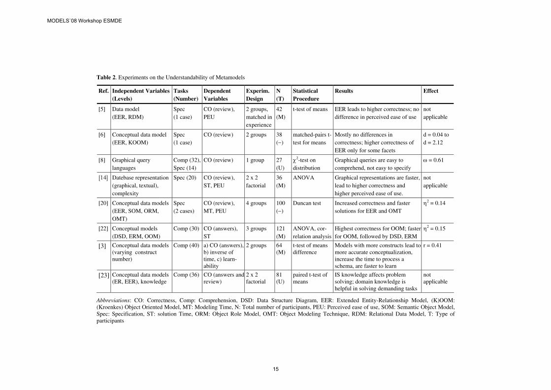
Table 2. Experiments on the Understandability of Metamodels
Ref. Independent Variables (Levels)
Tasks (Number)
Dependent Variables
Experim. Design
N (T)
Statistical Procedure
Results Effect
[5] Data model (EER, RDM)
Spec (1 case)
CO (review), PEU
2 groups, matched in experience
42 (M)
t-test of means EER leads to higher correctness; no difference in perceived ease of use
not applicable
[6] Conceptual data model (EER, KOOM)
Spec (1 case)
CO (review) 2 groups 38 (−)
matched-pairs t-test for means
Mostly no differences in correctness; higher correctness of EER only for some facets
d = 0.04 to d = 2.12
[8] Graphical query languages
Comp (32), Spec (14)
CO (review) 1 group 27 (U)
χ2-test on distribution
Graphical queries are easy to comprehend, not easy to specify
ω = 0.61
[14] Datebase representation (graphical, textual), complexity
Spec (20) CO (review), ST, PEU
2 x 2 factorial
36 (M)
ANOVA Graphical representations are faster, lead to higher correctness and higher perceived ease of use.
not applicable
[20] Conceptual data models (EER, SOM, ORM, OMT)
Spec (2 cases)
CO (review), MT, PEU
4 groups 100 (−)
Duncan test Increased correctness and faster solutions for EER and OMT
η2 = 0.14
[22] Conceptual models (DSD, ERM, OOM)
Comp (30) CO (answers), ST
3 groups 121 (M)
ANOVA, cor-relation analysis
Highest correctness for OOM; faster for OOM, followed by DSD, ERM
η2 = 0.15
[3] Conceptual data models (varying construct number)
Comp (40) a) CO (answers), b) inverse of time, c) learn-ability
2 groups 64 (M)
t-test of means difference
Models with more constructs lead to more accurate conceptualization, increase the time to process a schema, are faster to learn
r = 0.41
[23] Conceptual data models (ER, EER), knowledge
Comp (36) CO (answers and review)
2 x 2 factorial
81 (U)
paired t-test of means
IS knowledge affects problem solving; domain knowledge is helpful in solving demanding tasks
not applicable
Abbreviations: CO: Correctness, Comp: Comprehension, DSD: Data Structure Diagram, EER: Extended Entity-Relationship Model, (K)OOM: (Kroenkes) Object Oriented Model, MT: Modeling Time, N: Total number of participants, PEU: Perceived ease of use, SOM: Semantic Object Model, Spec: Specification, ST: solution Time, ORM: Object Role Model, OMT: Object Modeling Technique, RDM: Relational Data Model, T: Type of participants
MODELS`08 Workshop ESMDE
15
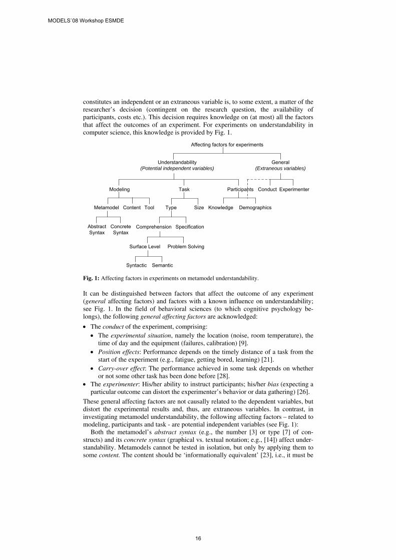
constitutes an independent or an extraneous variable is, to some extent, a matter of the researcher’s decision (contingent on the research question, the availability of participants, costs etc.). This decision requires knowledge on (at most) all the factors that affect the outcomes of an experiment. For experiments on understandability in computer science, this knowledge is provided by Fig. 1.
Affecting factors for experiments
Understandability(Potential independent variables)
General(Extraneous variables)
Modeling ParticipantsTask Conduct Experimenter
Metamodel Content
AbstractSyntax
ConcreteSyntax
DemographicsKnowledgeType Size
Comprehension Specification
Surface Level Problem Solving
Syntactic Semantic
Tool
Fig. 1: Affecting factors in experiments on metamodel understandability.
It can be distinguished between factors that affect the outcome of any experiment (general affecting factors) and factors with a known influence on understandability; see Fig. 1. In the field of behavioral sciences (to which cognitive psychology be-longs), the following general affecting factors are acknowledged:
• The conduct of the experiment, comprising: • The experimental situation, namely the location (noise, room temperature), the
time of day and the equipment (failures, calibration) [9]. • Position effects: Performance depends on the timely distance of a task from the
start of the experiment (e.g., fatigue, getting bored, learning) [21]. • Carry-over effect: The performance achieved in some task depends on whether
or not some other task has been done before [28]. • The experimenter: His/her ability to instruct participants; his/her bias (expecting a
particular outcome can distort the experimenter’s behavior or data gathering) [26].
These general affecting factors are not causally related to the dependent variables, but distort the experimental results and, thus, are extraneous variables. In contrast, in investigating metamodel understandability, the following affecting factors – related to modeling, participants and task - are potential independent variables (see Fig. 1):
Both the metamodel’s abstract syntax (e.g., the number [3] or type [7] of con-structs) and its concrete syntax (graphical vs. textual notation; e.g., [14]) affect under-standability. Metamodels cannot be tested in isolation, but only by applying them to some content. The content should be ‘informationally equivalent’ [23], i.e., it must be
MODELS`08 Workshop ESMDE
16
possible to model this content by any of the investigated metamodels, and the content should be comparably difficult. Finally, the tool used to create or present models (e.g., its navigation or dynamic layout capabilities) influences understandability.
Among the affecting factors, participants play an intermediate role: Their demo-graphic characteristics (e.g., age, gender) affect any experiment [1] and, thus, also understandability. For example, the participants’ age is treated as an independent variable in MIS research [15]. Knowledge comprises experience and skills related to domain and metamodel as well as general mental abilities. Domain knowledge dis-torts results on metamodel understandability as it enables inferences [23]. Metamodel knowledge is usually provided in preparing the participants for the experiment.
Tasks in experiments on understandability can be characterized by their type and size. As Table 2 indicates, the task types used are comprehension or specification (defined in Section 1), which agree to the dependent variables cognitive psychology suggests (see Section 4.3). Comprehension tasks can be subdivided into surface-level understanding and problem-solving tasks [17]. In problem-solving tasks, participants are requested to determine whether and how certain information can be retrieved from an artifact created by applying the metamodel. In contrast, syntactic surface level understanding tasks refer to the constructs of the metamodel and their relationships (e.g., ‘How many attributes describe the entity type ORDER?’), whereas semantic tasks assess the understanding of the contents described (e.g., ‘Every employee has (a) a unique employee number, (b) more than one employee number.’) [17]. An influence of the size of some task, e.g., the complexity of the database described by some metamodel, is generally assumed, but it was only marginally significant in [14].
Depending on the decision of the researcher, a potential independent variable is either systematically manipulated or becomes an extraneous variable. Extraneous variables decrease the internal validity of experiments, i.e., the degree to which the variation of the dependent variables can be attributed to the independent variables (rather than to some other factor) [28]. Consequently, extraneous variables must be controlled, which is main constituent of experimental design (see Section 4.2).
4.2 Experimental Design
An experimental design can be regarded as a general plan for (types of) experiments that joins independent variables and control techniques for extraneous variables. The main control techniques are removing, constancy and randomization [26], [28]; they should be applied in the following order: 1. Remove the extraneous variable (EV), especially if it is related to the experimental
situation (e.g., use a quite room). 2. If the EV cannot be removed, its influence on the dependent variable is known and
the sample is small, keep the EV constant. Constancy guarantees that all conditions are identical except for the manipulation of the independent variable, but reduces the external validity of the experiment, i.e., its generalizability [26].
3. If sample size does not matter and the influence of some irremovable EV on the dependent variable is not surely known (e.g., gender), must be neutralized (e.g., position or carry-over effects) or should be equated (e.g., age, knowledge), randomize the EV. Randomization increases the external validity of experiments.
MODELS`08 Workshop ESMDE
17
Table 3. Summary of Experimental Designs
Design Between-subjects Within-subjects Block (Matched) Factorial
No. of IV (levels)
1 (n) 1 (n) 1 (n) m > 1 (n)
Groups n 1 n m × n
Pro:
No carry-over effects • Simple • Small samples • Constancy of
individual characteristics
• Precise • No carry-over
effects • Individual dif-
ferences balanced
Interactions between IV can be examined
Contra: • Unequal groups possible
• Large samples
• Carry-over effects • Experimenter bias
• Effort • Matching factor
must exist
• Large samples • Difficult to in-
terpret for m > 3
EV Control
Randomization Constancy Constancy and Randomization
Randomization
Statistical test procedures
Metric DV
♦: independent t ∗: F-test, ANOVA
♦: paired t-test of means ∗: MANOVA
MANOVA
Ordinal DV
♦: Mann-Whitney U ∗: Kruskal-Wallis H
♦: Wilcoxon signed rank test (matched) ∗: Friedman’s χ2
-
Nominal DV
♦/∗: χ2 contingency test
♦: Sign test, McNemar’s test of change ∗: Cochran’s Q-test
-
Sample Size ♣
1-t: ni = 20 [50] 2-t: ni = 25 [60]
1-t: N = 11 [23] 2-t: N = 15 [35]
see between- subjects
2-t only, m = 3: ni = 20 [50]
♣ To detect a large [a medium] effect (see Table 1) with (1 - β) = 0.8 and α = 0.05.
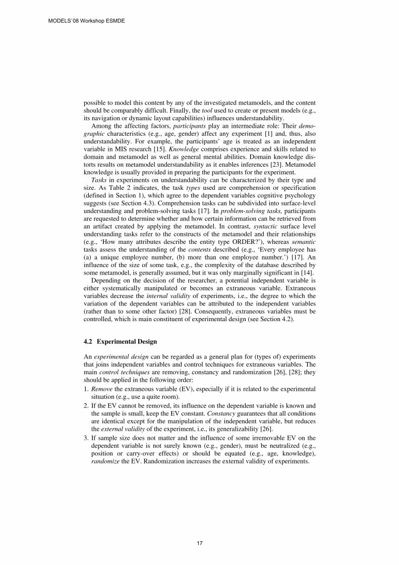
The experimental design to be chosen depends on (1) the number of independent variables and (2) the control technique. Table 3 summarizes typical experimental designs and their (dis-) advantages (for details, see [9], [26], [28]). Experimental design and the dependent variables determine the statistical test procedures for evaluation (see Table 3). For each statistical procedure, an effect size measure exists (see Table 1). The sample size required to detect a small, medium or large effect for a given experimental design and statistical test procedure can be calculated by power analysis (e.g., [9], [10]); the resulting recommendations are given in Table 3.
4.3 Affected Factors
The dependent variable is the one on which the effect of the independent variable is measured. Behaviorism, the origin of experimental research in psychology, requires the dependent variable to refer to observable behavior [1]. Thus, ‘perceived ease of use’ (even though applied, see Table 2) is not an acceptable dependent variable. Instead, the following measures of behavior are common [26]: 1. Frequency, e.g., the number of correct answers or solved problems. 2. Selection, e.g., which of several answers is chosen.
MODELS`08 Workshop ESMDE
18
3. Response latency (or response time), which is concerned with how long it takes for a behavior to be emitted, e.g., how quickly a participant reacts.
4. Response duration, i.e., the length of time some behavior occurs (e.g., how long a participant deals with a task).
5. Amplitude, measuring the strength of response. The dependent variables in experiments on metamodel understandability (see Table 2) use these measures as follows: Solution time refers to response latency and modeling time to response duration. If correctness is verified by multiple-choice questions (e.g., [17]), it is based on the measure ‘selection’, whereas numbers of correct answers are a measure of frequency.
Thus, the dependent variables in experiments on understandability in computer science are well-grounded in cognitive psychology. Completeness could be achieved by measuring amplitude, which, however, is mainly common in neuroscience [1], and by using selection of some metamodel from a list in specification tasks.
5 Conclusion
Missing comparability of the integrated studies is a major reservation about meta-analysis [27]. But, comparability of heterogeneous experiments can be achieved by methodologically equalizing differences among experiments [13] – provided that the differences are known. In other words, sound meta-analysis is possible if all variables and (for EV) their control techniques are reported. The taxonomies provided by the framework (see Section 4) help researchers to compile such lists; further advances can be achieved by web-publishing them (and the related experimental studies) as well as by tool support for the experiments on understandability. A simple open-source tool called notate already exists (http://sourceforge.net/projects/notate). It has been successfully applied in experiments on understandability [24] and can be extended to cover the complete framework of Section 4.
In contrast to the narrow view of MIS research, extensibility and flexibility are major requirements for a framework to investigate understandability in computer science, since the nature of language understanding in general still is an open research question in cognitive psychology [1]. Workshops are an appropriate place to exchange experience in this field and to advance the framework proposed here.
References 1. Anderson, J.R.: Cognitive Psychology and its Implications. 5th ed., Worth, New York (2000) 2. Aranda, J., Ernst, N., Horkoff, J., Easterbrook, S.: A Framework for Empirical Evaluation of
Model Comprehensibility. Proc. Intern. Workshop on Modeling in Software Engineering (MISE’07), Minneapolis/ MN. IEEE (2007)
3. Bajaj, A.: The effect of the number of concepts on the readability of schemas: an empirical study with data models. Requirements Engineering 9, 261-270 (2004)
4. Basili, V.R., Selby, R.W., Hutchens, D.H.: Experimentation in Software Engineering. IEEE Transactions on Software Engineering SE-12 7, 733-743 (1986)
MODELS`08 Workshop ESMDE
19
5. Batra, D., Hoffer, J.A., Bostrom, R.P.: Comparing Representations with Relational and EER Models. Comm. of the ACM 33, 126–139 (1990)
6. Bock, D., Ryan, T.: Accuracy in Modeling with Extended Entity Relationship and Object Oriented Data Models. J. of Database Management 4, 30-39 (1993)
7. Bodart, F., Patel, A., Sim, M., Weber, R.: Should Optional Properties Be Used in Conceptual Modelling? A Theory and Three Empirical Tests. Information Systems Research 12, 384-405 (2001)
8. Chan, H.C.: Naturalness of Graphical Queries Based on the Entity Relationship Model. J. of Database Management 6, 3–13 (1995)
9. Clark-Carter, D.: Quantitative psychological research. Psychology Press, Hove (2004) 10. Cohen, J.: Statistical Power Analysis for the Behavioral Sciences. 2nd ed., Erlbaum,
Hillsdale (1988) 11. Gemino, A., Wand, Y.: A framework for empirical evaluation of conceptual modeling
techniques. Requirements Engineering 9, 248-260 (2004) 12. Hayes, P.J.: Some Problems and Non-Problems in Representation Theory. Proc. of the
AISB Summer Conference. University of Sussex, 63-79 (1974) 13. Hwang, M.I.: The Use of Meta-Analysis in MIS: Research: Promises and Problems. The
DATA BASE for Advances in Information Systems 27, 35-48 (1996) 14. Jamison, W., Teng, J.T.C.: Effects of Graphical Versus Textual Representation of Database
Structure on Query Performance. J. of Database Management 4, 16–23 (1993) 15. Jenkins, M.A.: MIS Design Variables and Decision Making Performance. UMI Research
Press, Ann Arbor (1976) 16. Jedlitschka, A., Pfahl, D.: Reporting Guidelines for Controlled Experiments in Software
Engineering. Proc. of ACM/IEEE Intern. Symposium on Software Engineering 2004 (ISESE 2004), 261-270. IEEE (2004)
17. Khatri, V., Vessey, I., Ramesh, V., Clay, P., Park, S.-J.: Understanding Conceptual Schemas: Exploring the Role of Application and IS domain Knowledge. Information Systems Research 17, 81-99 (2006)
18. Kitchenham, B. et al.: Evaluation guidelines for reporting empirical software engineering Studies. Empirical Software Engineering 13, 97-121 (2008)
19. Kitchenham, B.A. et al.: Preliminary Guidelines for Empirical Research in Software Engineering. IEEE Transactions on Software Engineering 28, 721-734 (2002)
20. Lee, H., Choi, B.G.: A Comparative Study of Conceptual Data Modeling Techniques. J. of Database Management 9, 26-35 (1998)
21. Mook, D.: Classic experiments in psychology. Greenwood, Westport (2004) 22. Palvia, P.C., Liao, C., To, P.-L.: The Impact of Conceptual Data Models on End-User
Performance. J. of Database Management 3, 4-15 (1992) 23. Parsons, J., Cole, L.: What do the pictures mean? Guidelines for experimental evaluation of
representation fidelity in diagrammatical conceptual modelling techniques. Data & Know-ledge Engineering 55, 327-342 (2005)
24. Patig, S.: A Practical Guide to Testing the Understandability of Notations. Proc. 5th Asia-Pacific Conf. on Conceptual Modelling (APCCM 2008). CRPIT Volume 79. ACS, (2008)
25. Pickard, L.M., Kitchenham, B.A., Jones, P.W.: Combining empirical results in software engineering. Information and Software Technology 40, 811-812 (1998)
26. Robinson, P.W.: Fundamentals of Experimental Psychology, 2nd ed., Prentice-Hall, Engle-wood Cliffs (1981)
27. Rosenthal, R., DiMatteo, M.R.: Meta-Analysis: Recent Developments in Quantitative Methods for Literature Reviews. Annual review of psychology 52, 59-82 (2001)
28. Sarafino, E.P.: Research Methods: Using Processes and Procedures of Science to Underssand Behavior. Pearson, Upper Saddle River (2005)
29. Sloman, A.: Interactions Between Philosophy and Artificial Intelligence. Artificial Intelligence 2, 209–225 (1971)
MODELS`08 Workshop ESMDE
20
Empirical comparison of two class modelnormalization techniquesObstacles and questions ?
J.-R. Falleri1, M. Huchard1, and C. Nebut1
LIRMM, CNRS and Universite de Montpellier 2,161, rue Ada, 34392 Montpellier cedex 5, France
{falleri, huchard, nebut}@lirmm.fr
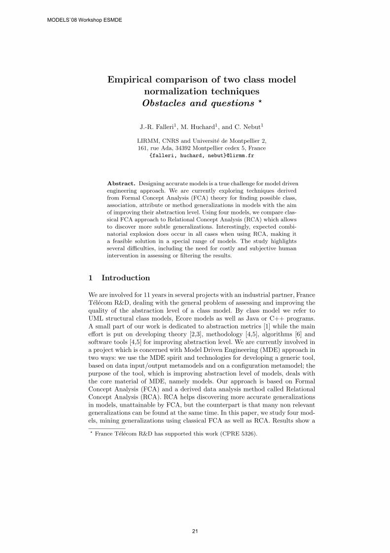
Abstract. Designing accurate models is a true challenge for model drivenengineering approach. We are currently exploring techniques derivedfrom Formal Concept Analysis (FCA) theory for finding possible class,association, attribute or method generalizations in models with the aimof improving their abstraction level. Using four models, we compare clas-sical FCA approach to Relational Concept Analysis (RCA) which allowsto discover more subtle generalizations. Interestingly, expected combi-natorial explosion does occur in all cases when using RCA, making ita feasible solution in a special range of models. The study highlightsseveral difficulties, including the need for costly and subjective humanintervention in assessing or filtering the results.
1 Introduction
We are involved for 11 years in several projects with an industrial partner, FranceTelecom R&D, dealing with the general problem of assessing and improving thequality of the abstraction level of a class model. By class model we refer toUML structural class models, Ecore models as well as Java or C++ programs.A small part of our work is dedicated to abstraction metrics [1] while the maineffort is put on developing theory [2,3], methodology [4,5], algorithms [6] andsoftware tools [4,5] for improving abstraction level. We are currently involved ina project which is concerned with Model Driven Engineering (MDE) approach intwo ways: we use the MDE spirit and technologies for developing a generic tool,based on data input/output metamodels and on a configuration metamodel; thepurpose of the tool, which is improving abstraction level of models, deals withthe core material of MDE, namely models. Our approach is based on FormalConcept Analysis (FCA) and a derived data analysis method called RelationalConcept Analysis (RCA). RCA helps discovering more accurate generalizationsin models, unattainable by FCA, but the counterpart is that many non relevantgeneralizations can be found at the same time. In this paper, we study four mod-els, mining generalizations using classical FCA as well as RCA. Results show a
? France Telecom R&D has supported this work (CPRE 5326).
MODELS`08 Workshop ESMDE
21
combinatorial explosion for RCA applied to the two Ecore models, but a reason-able result size for Java models. In the last case, the gain in obtaining relevant,more subtle, generalizations is not ruined by the necessity of mining these inter-esting generalizations into a huge amount of artifacts. In Section 2, we describethe research problem and the studied solutions. Section 3 presents the empiri-cal comparison which was conducted, as well as the difficulties encountered. Weconclude by a discussion in Section 4.
2 Clustering techniques for Class Model Normalization
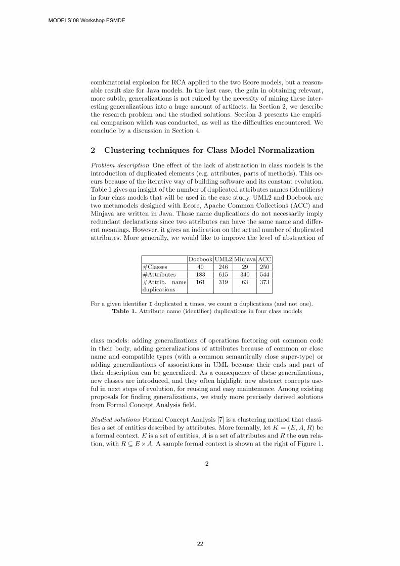
Problem description One effect of the lack of abstraction in class models is theintroduction of duplicated elements (e.g. attributes, parts of methods). This oc-curs because of the iterative way of building software and its constant evolution.Table 1 gives an insight of the number of duplicated attributes names (identifiers)in four class models that will be used in the case study. UML2 and Docbook aretwo metamodels designed with Ecore, Apache Common Collections (ACC) andMinjava are written in Java. Those name duplications do not necessarily implyredundant declarations since two attributes can have the same name and differ-ent meanings. However, it gives an indication on the actual number of duplicatedattributes. More generally, we would like to improve the level of abstraction of
Docbook UML2 Minjava ACC
#Classes 40 246 29 250
#Attributes 183 615 340 544
#Attrib. nameduplications
161 319 63 373
For a given identifier I duplicated n times, we count n duplications (and not one).Table 1. Attribute name (identifier) duplications in four class models
class models: adding generalizations of operations factoring out common codein their body, adding generalizations of attributes because of common or closename and compatible types (with a common semantically close super-type) oradding generalizations of associations in UML because their ends and part oftheir description can be generalized. As a consequence of these generalizations,new classes are introduced, and they often highlight new abstract concepts use-ful in next steps of evolution, for reusing and easy maintenance. Among existingproposals for finding generalizations, we study more precisely derived solutionsfrom Formal Concept Analysis field.
Studied solutions Formal Concept Analysis [7] is a clustering method that classi-fies a set of entities described by attributes. More formally, let K = (E,A, R) bea formal context. E is a set of entities, A is a set of attributes and R the own rela-tion, with R ⊆ E×A. A sample formal context is shown at the right of Figure 1.
2
MODELS`08 Workshop ESMDE
22
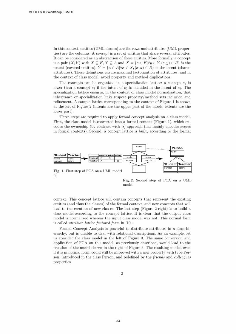
In this context, entities (UML classes) are the rows and attributes (UML proper-ties) are the columns. A concept is a set of entities that share several attributes.It can be considered as an abstraction of these entities. More formally, a conceptis a pair (X, Y ) with X ⊆ E, Y ⊆ A and X = {e ∈ E|∀y ∈ Y, (e, y) ∈ R} is theextent (covered entities), Y = {a ∈ A|∀x ∈ X, (x, a) ∈ R} is the intent (sharedattributes). These definitions ensure maximal factorization of attributes, and inthe context of class model, avoid property and method duplications.
The concepts can be organized in a specialization lattice: a concept c1 islower than a concept c2 if the intent of c2 is included in the intent of c1. Thespecialization lattice ensures, in the context of class model normalization, thatinheritance or specialization links respect property/method sets inclusion andrefinement. A sample lattice corresponding to the context of Figure 1 is shownat the left of Figure 2 (intents are the upper part of the labels, extents are thelower part).
Three steps are required to apply formal concept analysis on a class model.First, the class model is converted into a formal context (Figure 1), which en-codes the ownership (by contrast with [8] approach that mainly encodes accessin formal contexts). Second, a concept lattice is built, according to the formal
Fig. 1. First step of FCA on a UML model[9]
Fig. 2. Second step of FCA on a UMLmodel
context. This concept lattice will contain concepts that represent the existingentities (and thus the classes) of the formal context, and new concepts that willlead to the creation of new classes. The last step (Figure 2-right) is to build aclass model according to the concept lattice. It is clear that the output classmodel is normalized whereas the input class model was not. This normal formis called attribute lattice factored form in [10].
Formal Concept Analysis is powerful to distribute attributes in a class hi-erarchy, but is unable to deal with relational descriptions. As an example, letus consider the class model in the left of Figure 3. The same conversion andapplication of FCA on this model, as previously described, would lead to thecreation of the model shown in the right of Figure 3. The resulting model, evenif it is in normal form, could still be improved with a new property with type Per-son, introduced in the class Person, and redefined by the friends and colleaguesproperties.
3
MODELS`08 Workshop ESMDE
23
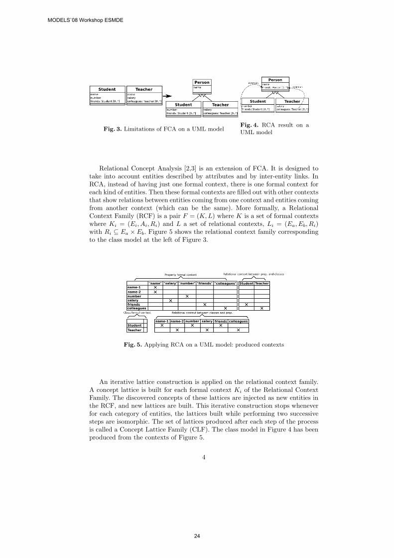
Fig. 3. Limitations of FCA on a UML modelFig. 4. RCA result on aUML model
Relational Concept Analysis [2,3] is an extension of FCA. It is designed totake into account entities described by attributes and by inter-entity links. InRCA, instead of having just one formal context, there is one formal context foreach kind of entities. Then these formal contexts are filled out with other contextsthat show relations between entities coming from one context and entities comingfrom another context (which can be the same). More formally, a RelationalContext Family (RCF) is a pair F = (K, L) where K is a set of formal contextswhere Ki = (Ei, Ai, Ri) and L a set of relational contexts, Li = (Ea, Eb, Ri)with Ri ⊆ Ea × Eb. Figure 5 shows the relational context family correspondingto the class model at the left of Figure 3.
Fig. 5. Applying RCA on a UML model: produced contexts
An iterative lattice construction is applied on the relational context family.A concept lattice is built for each formal context Ki of the Relational ContextFamily. The discovered concepts of these lattices are injected as new entities inthe RCF, and new lattices are built. This iterative construction stops wheneverfor each category of entities, the lattices built while performing two successivesteps are isomorphic. The set of lattices produced after each step of the processis called a Concept Lattice Family (CLF). The class model in Figure 4 has beenproduced from the contexts of Figure 5.
4
MODELS`08 Workshop ESMDE
24
3 An empirical comparison of Class Normalizationtechniques
In this section, we develop our view on an empirical study we began to carryout. We examine four facets: how a precise hypothesis we would like to checkis formulated, how the experiment is prepared, how it is conducted and finallyhow results are evaluated.
3.1 Formulating hypothesis
As presented on small examples, FCA and RCA are very attractive techniques.From a theoretical point of view, it can be shown that RCA finds relevant gener-alizations (abstractions) that are not obtained by FCA. From a practical pointof view, RCA is intrinsically much more combinatorial than FCA and it seemsmore difficult to fine-tune and control the huge set of produced generalizations.When the initial model contains long paths of associations, some inferred gener-alizations can have poor semantics and often mean something like (for a class)”class whose instances are linked to instances that are linked to instances thatare linked .... to instances of” a given initial class of the model.
The question we would like to answer is formulated as follows: ”Comparinggeneralizations produced by RCA versus those produced by FCA, and consider-ing the effort needed for parameterizing and using results of FCA/RCA, is RCAan interesting improvement in practice?”. This question is still too general, asseveral parameterizations are possible for FCA and RCA, depending of whatwe decide to encode in the tables (formal contexts for FCA and relational con-text family for RCA). This can be considered as part of the preparation of theexperiment (reducing the hypothesis).
3.2 Preparation of the experiment
Preparing the experiment in our context involved choosing class models on whichwe could test, choosing some procedures to make the data usable or more rel-evant, choosing the part of models to consider because many elements can beabstracted, and choosing the gauges for evaluating results.
In previous experiments with industrial models from France Telecom R&D,data were confidential and it was impossible even for us to see them and we justcould access to partial informations: partial examples of built abstractions andpartial results. Now, after several years, these models are no more confidentialbut people who designed the models are no more in charge of the projects andhave no time to devote to new experiments. The problem we face here is theobsolescence of data.
Choosing data To evaluate our class model normalization approach, we carriedout an experiment on four open source class models. Two of them, UML [11]and Docbook [12], are design models written in Ecore. The two others, ApacheCommons Collections (ACC) [13] and Minjava [14] (author: J.R. Falleri), areimplementation models, obtained by reverse-engineering on Java code. UMLstands for the UML 2.0 meta-model. Docbook is a meta-model of the Docbook
5
MODELS`08 Workshop ESMDE
25
language. Apache Commons Collections is a Java library that extends the Javacollections. Minjava is a Java reverse engineering tool that analyses Java byte-code and produces an Ecore compliant Java model conforming to a simple Javameta-model. Open source class models have the advantage of being available byeveryone. Designers may change or may be too busy to discuss with experimen-talists about the models, but at last, in industrial context this is often the samesituation.
Choosing configurations We restricted the experiment, for a first study, to partsof models composed of classes and attributes (properties in UML terms):
1. Basic FCA configuration (FCA1 ): it corresponds to the one in [10], thatgenerates a class and a property context and analyses the attribute ownershipto discover super-classes, based on attribute names.
2. Enhanced FCA configuration (FCA2 ): same as the previous configuration,but using information specific to the input language (e.g. static keyword inJava, cardinality in Ecore) to avoid incorrect generalizations.
3. Enhanced Properties configuration (RCA): a RCA configuration that gen-erates a class and a property context and analyses the attribute ownershipand the attribute type to discover super-classes and redefined properties.
Choosing gauges To understand the results of the application of FCA (resp.RCA) to our sample models, we use the produced lattice (resp. Concept Lat-tices Family). We classify the concepts of these lattices into three disjoint cat-egories. ExistingConcepts: for elements that were already present in the in-put class model; NewConcepts: for elements created during the RCA process;MergeConcepts: for the merge of existing elements from the input model.
The ExistingConcepts set is not really interesting since it contains only con-cepts representing the input entities. The NewConcepts set is very interesting.It contains the concepts that may introduce new useful elements (abstractionsof existing ones) in the class model. The MergeConcepts set is also interesting,since it contains the elements from the source model that have been consideredsimilar and therefore have led to the creation of the new elements. To presentthe result of our case study, we choose to use the two following quantities: N ,the number of new elements i.e. |NewConcepts|; M , the number of merges i.e.|MergeConcepts|.
Of course, the previous quantities show how the different configurations ofthe RCA process behave, but are unable to show the quality of these results.Metrics are a way of assessing quality, but they are not so easy to use: basedon current inheritance metrics from [15,16], it has been shown in [17] that in-heritance metrics (associated with size metrics) are useful in measuring softwarestability, but don’t really help in detecting concrete design problems.
In [18], the case study uses a structural metric to analyze the result of FCAapplication on real world class hierarchies. The chosen metric, called M2 is de-rived of the M1 metric introduced in [19]. This metric measures redundancy andinheritance quality. Basically, M2 is a weighted sum of the number of attributes
6
MODELS`08 Workshop ESMDE
26
and the number of inheritance links. To defavor the use of multiple inheritance,for a given class the inheritance links count as double after the first one. Thelower metric M2 is, the better the class model is designed.
Unfortunately, this metric can lead to wrong analysis of the class model. Ifwe imagine an output class model where a super-class has been found but is notcorrect (for instance because of homographs), the M2 metric will still considerthis output model as better than the input one. Moreover, this metric is notcompatible with the use of redefined properties or methods. If we use the classmodel shown in Figure 3, the metric M2 will be 24 for the input model, 22for the output model without attribute redefinition and 26 for the output classmodel with attribute redefinition. This clearly shows that this metric is unable tocorrectly measure the quality of a class model design when attribute redefinitionis used.
Results from FCA/RCA on class model could be assessed using recent pro-posals and results on specialization quality measurement [1,20]. But in this firstexperiment, four simple, specific metrics have been introduced based on humananalysis:. cn: number of concepts included in the NewConcepts set that are con-sidered as correct; a rate is obtained with cnr = cn/|NewConcepts|; cm: numberof concepts included in the MergeConcepts set that are considered as correct; arate is obtained with cmr = cm/|MergeConcepts|.
3.3 Experimenting
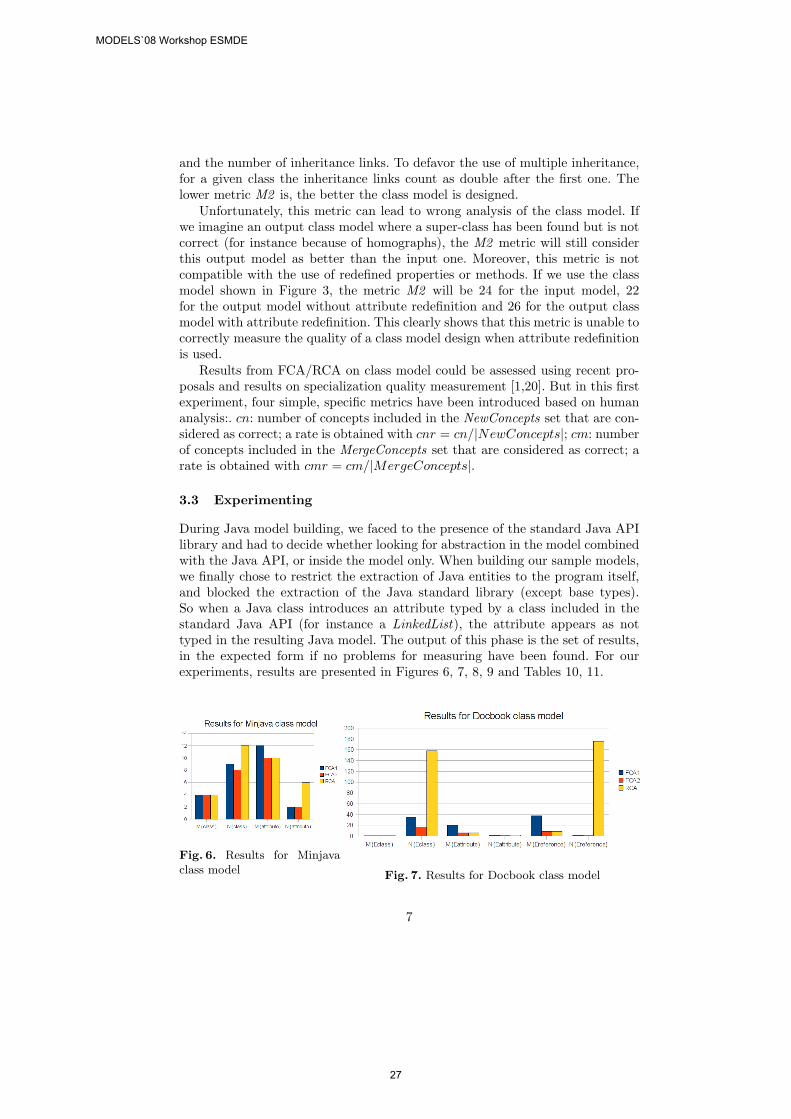
During Java model building, we faced to the presence of the standard Java APIlibrary and had to decide whether looking for abstraction in the model combinedwith the Java API, or inside the model only. When building our sample models,we finally chose to restrict the extraction of Java entities to the program itself,and blocked the extraction of the Java standard library (except base types).So when a Java class introduces an attribute typed by a class included in thestandard Java API (for instance a LinkedList), the attribute appears as nottyped in the resulting Java model. The output of this phase is the set of results,in the expected form if no problems for measuring have been found. For ourexperiments, results are presented in Figures 6, 7, 8, 9 and Tables 10, 11.
Fig. 6. Results for Minjavaclass model Fig. 7. Results for Docbook class model
7
MODELS`08 Workshop ESMDE
27
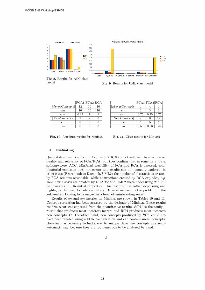
Fig. 8. Results for ACC classmodel Fig. 9. Results for UML class model
FCA1 FCA2 RCA
|MergeConcepts| 12 10 10
cm 10 10 10
cmr 0.83 1 1
|NewConcepts| 2 2 6
cn 0 0 0
cnr 0 0 0
Fig. 10. Attribute results for Minjava
FCA1 FCA2 RCA
|MergeConcepts| 4 4 4
cm 3 3 3
cmr 0.75 0.75 0.75
|NewConcepts| 9 8 12
cn 5 5 5
cnr 0.56 0.63 0.42
Fig. 11. Class results for Minjava
3.4 Evaluating
Quantitative results shown in Figures 6, 7, 8, 9 are not sufficient to conclude onquality and relevancy of FCA/RCA, but they confirm that in some data (Javasoftware here: ACC, MinJava) feasibility of FCA and RCA is assessed, com-binatorial explosion does not occurs and results can be manually explored; inother cases (Ecore models: Docbook, UML2) the number of abstractions createdby FCA remains reasonable, while abstractions created by RCA explodes, e.g.1534 new classes are created by RCA for the UML2 metamodel using 246 ini-tial classes and 615 initial properties. This last result is rather depressing andhighlights the need for adapted filters. Because we face to the problem of thegold-seeker: looking for a nugget in a heap of uninteresting rocks.
Results of cn and cm metrics on Minjava are shown in Tables 10 and 11.Concept correction has been assessed by the designer of Minjava. These resultsconfirm what was expected from the quantitative results. FCA1 is the configu-ration that produces most incorrect merges and RCA produces most incorrectnew concepts. On the other hand, new concepts produced by RCA could nothave been created using a FCA configuration and can contain useful concepts.However it is necessary to find a way to analyse those new concepts in a semi-automatic way, because they are too numerous to be analysed by hand.
8
MODELS`08 Workshop ESMDE
28
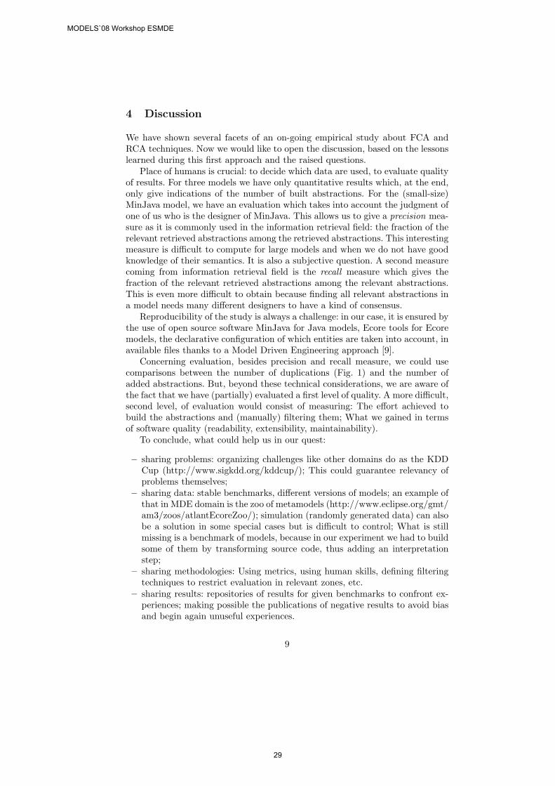
4 Discussion
We have shown several facets of an on-going empirical study about FCA andRCA techniques. Now we would like to open the discussion, based on the lessonslearned during this first approach and the raised questions.
Place of humans is crucial: to decide which data are used, to evaluate qualityof results. For three models we have only quantitative results which, at the end,only give indications of the number of built abstractions. For the (small-size)MinJava model, we have an evaluation which takes into account the judgment ofone of us who is the designer of MinJava. This allows us to give a precision mea-sure as it is commonly used in the information retrieval field: the fraction of therelevant retrieved abstractions among the retrieved abstractions. This interestingmeasure is difficult to compute for large models and when we do not have goodknowledge of their semantics. It is also a subjective question. A second measurecoming from information retrieval field is the recall measure which gives thefraction of the relevant retrieved abstractions among the relevant abstractions.This is even more difficult to obtain because finding all relevant abstractions ina model needs many different designers to have a kind of consensus.
Reproducibility of the study is always a challenge: in our case, it is ensured bythe use of open source software MinJava for Java models, Ecore tools for Ecoremodels, the declarative configuration of which entities are taken into account, inavailable files thanks to a Model Driven Engineering approach [9].
Concerning evaluation, besides precision and recall measure, we could usecomparisons between the number of duplications (Fig. 1) and the number ofadded abstractions. But, beyond these technical considerations, we are aware ofthe fact that we have (partially) evaluated a first level of quality. A more difficult,second level, of evaluation would consist of measuring: The effort achieved tobuild the abstractions and (manually) filtering them; What we gained in termsof software quality (readability, extensibility, maintainability).
To conclude, what could help us in our quest:
– sharing problems: organizing challenges like other domains do as the KDDCup (http://www.sigkdd.org/kddcup/); This could guarantee relevancy ofproblems themselves;
– sharing data: stable benchmarks, different versions of models; an example ofthat in MDE domain is the zoo of metamodels (http://www.eclipse.org/gmt/am3/zoos/atlantEcoreZoo/); simulation (randomly generated data) can alsobe a solution in some special cases but is difficult to control; What is stillmissing is a benchmark of models, because in our experiment we had to buildsome of them by transforming source code, thus adding an interpretationstep;
– sharing methodologies: Using metrics, using human skills, defining filteringtechniques to restrict evaluation in relevant zones, etc.
– sharing results: repositories of results for given benchmarks to confront ex-periences; making possible the publications of negative results to avoid biasand begin again unuseful experiences.
9
MODELS`08 Workshop ESMDE
29

Acknowledgments The authors would like to thank the anonymous refereesfor their suggestions and comments that helped to improve the paper.
References
1. Dao, M., Huchard, M., Libourel, T., Roume, C., Leblanc, H.: A New Approach toFactorization - Introducing Metrics. In: IEEE METRICS. (2002) 227–236
2. Dao, M., Huchard, M., Hacene, M.R., Roume, C., Valtchev, P.: Improving Gen-eralization Level in UML Models Iterative Cross Generalization in Practice. In:ICCS. Volume 3127 of LNCS., Springer (2004) 346–360
3. Huchard, M., Hacene, M.R., Roume, C., Valtchev, P.: Relational concept discoveryin structured datasets. Ann. Math. Artif. Intell. 49(1-4) (2007) 39–76
4. Arevalo, G., Falleri, J.R., Huchard, M., Nebut, C.: Building abstractions in classmodels: Formal concept analysis in a model-driven approach. In: MoDELS. Volume4199 of LNCS., Springer (2006) 513–527
5. Falleri, J.R., Huchard, M., Nebut, C., Arevalo, G.: A Model Driven Engineeringapproach for making generic FCA/RCA tools. In: Proceedings of the Fifth Inter-national Conference on Concept Lattices and Their Applications (CLA’07). (2007)229–252
6. Arevalo, G., Berry, A., Huchard, M., Perrot, G., Sigayret, A.: Performances ofGalois Sub-hierarchy-building Algorithms. In: ICFCA. Volume 4390 of LNCS.,Springer (2007) 166–180
7. Ganter, B., Wille, R.: Formal Concept Analysis: Mathematical Foundations.Springer-Verlag New York, Inc. Secaucus, NJ, USA (1997)
8. Snelting, G., Tip, F.: Understanding class hierarchies using concept analysis. ACMTrans. Program. Lang. Syst. 22(3) (2000) 540–582
9. Falleri, J.R., Huchard, M., Nebut, C.: A generic approach for class model normal-ization. In: Proc. of ASE’08, short paper. (to appear)
10. Godin, R., Valtchev, P.: Formal concept analysis-based class hierarchy design inobject-oriented software development. In: Formal Concept Analysis. Volume 3626of LNCS., Springer (2005) 304–323
11. Eclipse: UML2 EMF Plugin. http://www.eclipse.org/modeling/mdt/?project=uml2(2008)
12. Triskell: Docbook metamodel. http://www.kermeta.org (2008)13. : Apache Foundation: Apache Commons Collections. http: //commons.apache.org/
collections (2008)14. Falleri, J.R.: Minjava. http://code.google.com/p/minjava/ (2008)15. Chidamber, S.R., Kemerer, C.F.: A Metrics Suite for Object Oriented Design.
IEEE Trans. Software Eng. 20(6) (1994) 476–49316. Lorenz, M., Kidd, J.: Object-Oriented Software Metrics: A Practical Guide.
Prentice-Hall (1994)17. Demeyer, S., Ducasse, S.: Metrics, Do They Really Help? In: LMO, Hermes (1999)
69–8218. Godin, R., Mili, H., Mineau, G., Missaoui, R., Arfi, A., Chau, T.: Design of class
hierarchies based on concept,(Galois) lattices. Theory and Practice of Object Sys-tems 4(2) (1998) 117–134
19. Lieberherr, K., Bergstein, P., Silva-Lepe, I.: From objects to classes: algorithms foroptimal object-orienteddesign. Software Engineering Journal 6(4) (1991) 205–228
20. Breesam, K.M.: Metrics for Object-Oriented Design Focusing on Class InheritanceMetrics. In: DepCoS-RELCOMEX, IEEE Computer Society (2007) 231–237
10
MODELS`08 Workshop ESMDE
30
Assessing the Power of A Visual Notation- Preliminary Contemplations on Designing a Test -
Dominik Stein and Stefan Hanenberg
Universität Duisburg-Essen{ dominik.stein, stefan.hanenberg }@icb.uni-due.de
Abstract. This paper reports on preliminary thoughts which have beenconducted in designing an empirical experiment to assess the comprehensibilityof a visual notation in comparison to a textual notation. The paper sketchesshortly how a corresponding hypothesis could be developed. Furthermore, itpresents several recommendations that aim at the reduction of confoundingeffects. It is believed that these recommendations are applicable to otherexperiments in the domain of MDE, too. Finally, the paper reports on initialexperiences that have been made while formulating test questions.
1 In troduction
Although modeling does not imply visualization, people often consider the visualrepresentation of models to be a key characteristic of modeling. One reason to thiscould be that modeling techniques such as State Machines or Petri-Nets are oftentaught and explained with help of circles and arrows rather than in terms ofmathematical sets and functions. Apart from that, other kinds of modeling, e.g. datamodeling with help of Entity-Relationship-Diagrams, make heavy use of visualrepresentations, although the same concepts could be specified in a purely textualmanner, too.
However, let alone the impression that visual representations are considered veryappealing by a broad range of developers, customers, maintainers, students, etc., ascientific question would be if visual representations actual yield any extra benefit tosoftware development, maintenance, or teaching, etc.
Driven by a personal belief of the authors that this extra benefit exists, this paperreports on preliminary thoughts which have been conducted in designing an empiricalexperiment. The goal of this empirical experiment is to assess (such a "soft" propertyas) the "comprehensibility" of a visual notation in comparison to a textual notation.
This paper does not formulate a concrete hypothesis. Instead, it conducts generalcontemplation about hypotheses that are concerned with the evaluation of"comprehensibility". In particular, the paper presents several recommendations thataim at the reduction of confounding effects while running the test. It is suggested thatthese recommendations should be obeyed in other experiments in the domain ofMDE, too. Furthermore, the paper reports on experiences that have been made whileformulating the test questions for a test on comprehensibility.
The paper is structured as follows: In section 2, the process to define a hypothesisis outlined. In sections 3 and 4, a couple of considerations are presented in order to
MODELS`08 Workshop ESMDE
31
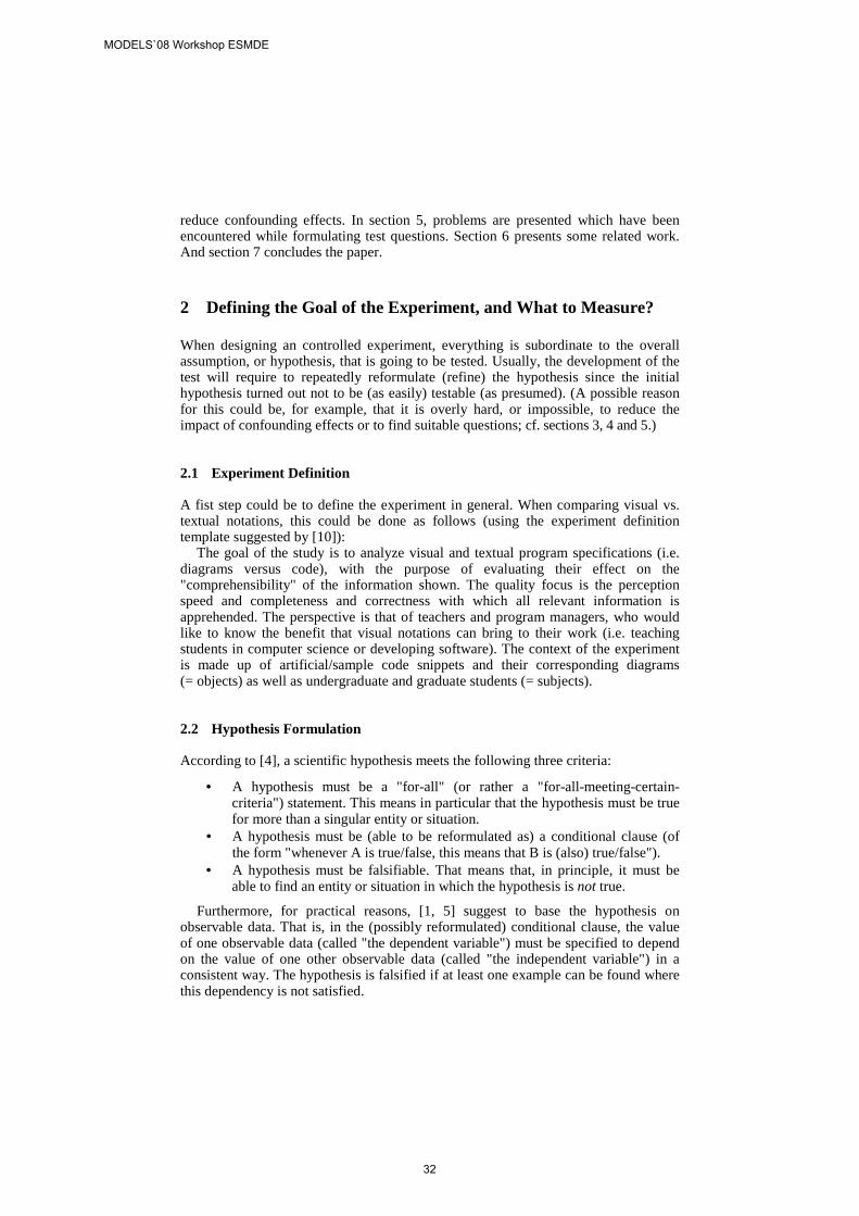
reduce confounding effects. In section 5, problems are presented which have beenencountered while formulating test questions. Section 6 presents some related work.And section 7 concludes the paper.
2 Defining the Goal of the Experiment, and What to Measure?
When designing an controlled experiment, everything is subordinate to the overallassumption, or hypothesis, that is going to be tested. Usually, the development of thetest will require to repeatedly reformulate (refine) the hypothesis since the initialhypothesis turned out not to be (as easily) testable (as presumed). (A possible reasonfor this could be, for example, that it is overly hard, or impossible, to reduce theimpact of confounding effects or to find suitable questions; cf. sections 3, 4 and 5.)
2.1 Experiment Definition
A fist step could be to define the experiment in general. When comparing visual vs.textual notations, this could be done as follows (using the experiment definitiontemplate suggested by [10]):
The goal of the study is to analyze visual and textual program specifications (i.e.diagrams versus code), with the purpose of evaluating their effect on the"comprehensibility" of the information shown. The quality focus is the perceptionspeed and completeness and correctness with which all relevant information isapprehended. The perspective is that of teachers and program managers, who wouldlike to know the benefit that visual notations can bring to their work (i.e. teachingstudents in computer science or developing software). The context of the experimentis made up of artificial/sample code snippets and their corresponding diagrams(= objects) as well as undergraduate and graduate students (= subjects).
2.2 Hypothesis Formulation
According to [4], a scientific hypothesis meets the following three criteria:
• A hypothesis must be a "for-all" (or rather a "for-all-meeting-certain-criteria") statement. This means in particular that the hypothesis must be truefor more than a singular entity or situation.
• A hypothesis must be (able to be reformulated as) a conditional clause (ofthe form "whenever A is true/false, this means that B is (also) true/false").
• A hypothesis must be falsifiable. That means that, in principle, it must beable to find an entity or situation in which the hypothesis is not true.
Furthermore, for practical reasons, [1, 5] suggest to base the hypothesis onobservable data. That is, in the (possibly reformulated) conditional clause, the valueof one observable data (called "the dependent variable") must be specified to dependon the value of one other observable data (called "the independent variable") in aconsistent way. The hypothesis is falsified if at least one example can be found wherethis dependency is not satisfied.
MODELS`08 Workshop ESMDE
32
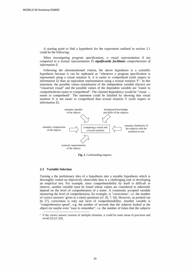
A starting point to find a hypothesis for the experiment outlined in section 2.1could be the following:
When investigating program specifications, a visual representation X (ascompared to a textual representation Y) significantly facilitates comprehension ofinformation Z.
Following the aforementioned criteria, the above hypothesis is a scientifichypothesis because it can be rephrased as "whenever a program specification isrepresented using a visual notation X, it is easier to comprehend (with respect toinformation Z) than an equivalent representation using a textual notation Y". In thisstatement, the possible values (treatments) of the independent variable (factor) are"visual/not visual" and the possible values of the dependent variable are "easier tocomprehend/not easier to comprehend". The claimed dependency would be "visual →easier to comprehend". The statement could be falsified by showing that visualnotation X is not easier to comprehend than textual notation Y (with respect toinformation Z).
comparing a visual anda textual notation
background knowledgeand skills of the subjects
semantic familiarity ofthe subjects with the
notations to test
semantic compressionof the objects
semantic equalityof the objects
syntactic representationof the objects
Fig. 1. Confounding impacts.
2.3 Variable Selection
Turning a the preliminary idea of a hypothesis into a testable hypothesis which isthoroughly rooted on objectively observable data is a challenging task in developingan empirical test. For example, since comprehensibility by itself is difficult toobserve, another variable must be found whose values are considered to inherentlydepend on the level of comprehension of a tester. A commonly accepted variablemeasuring the level of comprehension, for example, is "correctness", i.e. the numberof correct answers1 given to a (test) questions (cf. [8, 7, 6]). However, as pointed outby [7], correctness is only one facet of comprehensibility. Another variable is"comprehension speed", e.g. the number of seconds that the subjects looked at theobject (or maybe even "easy to remember", i.e. the number of times that the subjects
1 if the correct answer consists of multiple elements, it could be some mean of precision and
recall [2] (cf. [6]).
MODELS`08 Workshop ESMDE
33
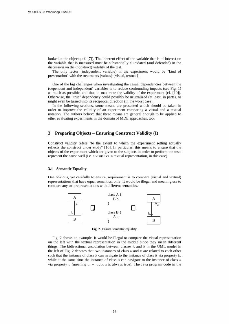
looked at the objects; cf. [7]). The inherent effect of the variable that is of interest onthe variable that is measured must be substantially elucidated (and defended) in thediscussion on the (construct) validity of the test.
The only factor (independent variable) in the experiment would be "kind ofpresentation" with the treatments (values) {visual, textual}.
One of the big challenges when investigating the casual dependencies between the(dependent and independent) variables is to reduce confounding impacts (see Fig. 1)as much as possible, and thus to maximize the validity of the experiment (cf. [10]).Otherwise, the "true" dependency could possibly be neutralized (at least, in parts), ormight even be turned into its reciprocal direction (in the worst case).
In the following sections, some means are presented which should be taken inorder to improve the validity of an experiment comparing a visual and a textualnotation. The authors believe that these means are general enough to be applied toother evaluating experiments in the domain of MDE approaches, too.
3 Preparing Objects – Ensuring Construct Validity (I)
Construct validity refers "to the extent to which the experiment setting actuallyreflects the construct under study" [10]. In particular, this means to ensure that theobjects of the experiment which are given to the subjects in order to perform the testsrepresent the cause well (i.e. a visual vs. a textual representation, in this case).
3.1 Semantic Equality
One obvious, yet carefully to ensure, requirement is to compare (visual and textual)representations that have equal semantics, only. It would be illegal and meaningless tocompare any two representations with different semantics.
class A {B b;
}
class B {A a;
}
A
B
a
b⇔⇔⇔⇔⇔⇔⇔⇔
A
B
a
b
Fig. 2. Ensure semantic equality.
Fig. 2 shows an example. It would be illegal to compare the visual representationon the left with the textual representation in the middle since they mean differentthings. The bidirectional association between classes A and B in the UML model inthe left of Fig. 2 denotes that two instances of class A and B are related to each othersuch that the instance of class A can navigate to the instance of class B via property b,while at the same time the instance of class B can navigate to the instance of class Avia property a (meaning a = a.b.a is always true). The Java program code in the
MODELS`08 Workshop ESMDE
34
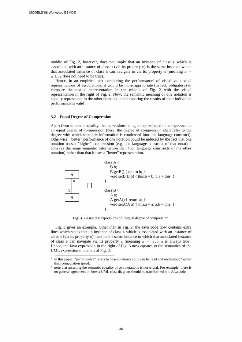
middle of Fig. 2, however, does not imply that an instance of class A which isassociated with an instance of class B (via its property b) is the same instance whichthat associated instance of class B can navigate to via its property a (meaning a =a.b.a does not need to be true).
Hence, in an empirical test comparing the performance2 of visual vs. textualrepresentations of associations, it would be more appropriate (in fact, obligatory) tocompare the textual representation in the middle of Fig. 2 with the visualrepresentation in the right of Fig. 2. Now, the semantic meaning of one notation isequally represented in the other notation, and comparing the results of their individualperformance is valid3.
3.2 Equal Degree of Compression
Apart from semantic equality, the expressions being compared need to be expressed atan equal degree of compression (here, the degree of compression shall refer to thedegree with which semantic information is condensed into one language construct).Otherwise, "better" performance of one notation could be induced by the fact that onenotation uses a "higher" compression (e.g. one language construct of that notationconveys the same semantic information than four language constructs of the othernotation) rather than that it uses a "better" representation.
A
B
a
b
class A {B b;B getB() { return b; }void setB(B b) { this.b = b; b.a = this; }
}
class B {A a;A getA() { return a; }void setA(A a) { this.a = a; a.b = this; }
}
⇔⇔⇔⇔
Fig. 3. Do not test expressions of unequal degree of compression.
Fig. 3 gives an example. Other than in Fig. 2, the Java code now contains extralines which states that an instance of class A which is associated with an instance ofclass B (via its property b) must be the same instance to which that associated instanceof class B can navigate via its property a (meaning a = a.b.a is always true).Hence, the Java expression in the right of Fig. 3 now equates to the semantics of theUML expression in the left of Fig. 3.
2 in this paper, "performance" refers to "the notation's ability to be read and understood" rather
than computation speed.3 note that asserting the semantic equality of two notations is not trivial. For example, there is
no general agreement on how a UML class diagram should be transformed into Java code.
MODELS`08 Workshop ESMDE
35
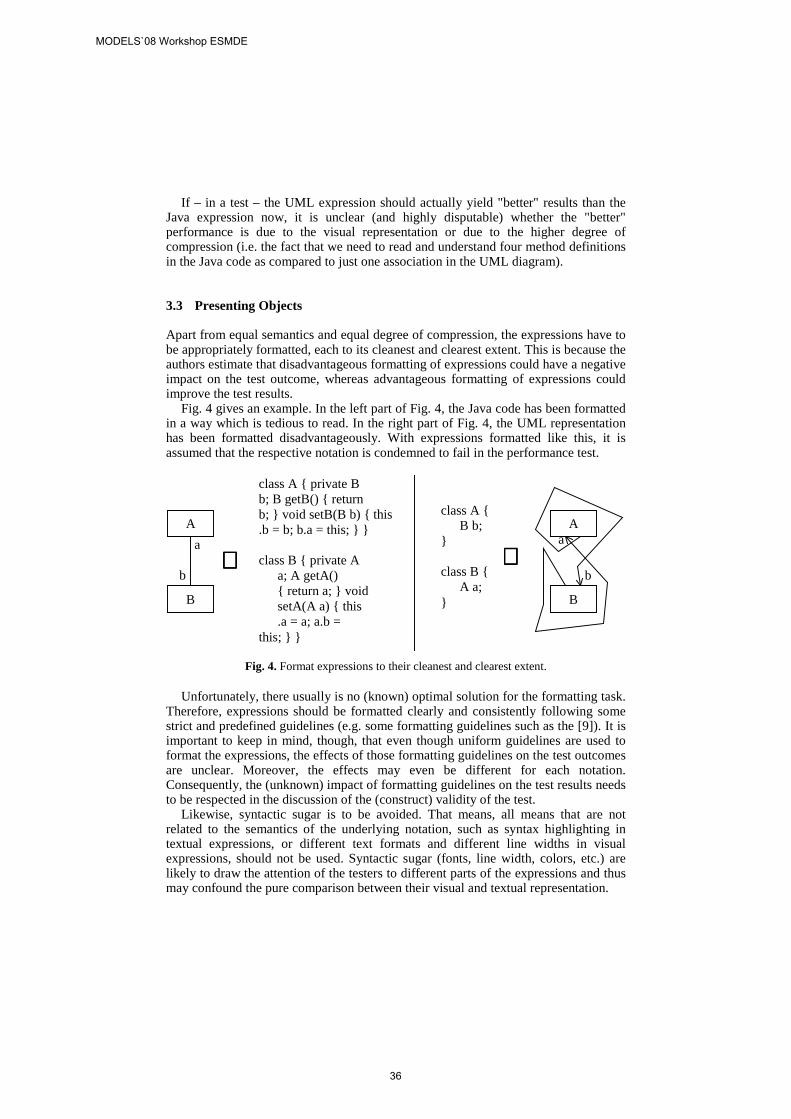
If – in a test – the UML expression should actually yield "better" results than theJava expression now, it is unclear (and highly disputable) whether the "better"performance is due to the visual representation or due to the higher degree ofcompression (i.e. the fact that we need to read and understand four method definitionsin the Java code as compared to just one association in the UML diagram).
3.3 Presenting Objects
Apart from equal semantics and equal degree of compression, the expressions have tobe appropriately formatted, each to its cleanest and clearest extent. This is because theauthors estimate that disadvantageous formatting of expressions could have a negativeimpact on the test outcome, whereas advantageous formatting of expressions couldimprove the test results.
Fig. 4 gives an example. In the left part of Fig. 4, the Java code has been formattedin a way which is tedious to read. In the right part of Fig. 4, the UML representationhas been formatted disadvantageously. With expressions formatted like this, it isassumed that the respective notation is condemned to fail in the performance test.
A
B
a
b
class A { private Bb; B getB() { returnb; } void setB(B b) { this.b = b; b.a = this; } }
class B { private Aa; A getA(){ return a; } voidsetA(A a) { this.a = a; a.b =
this; } }
⇔⇔⇔⇔
class A {B b;
}
class B {A a;
}
⇔⇔⇔⇔A
B
a
b
Fig. 4. Format expressions to their cleanest and clearest extent.
Unfortunately, there usually is no (known) optimal solution for the formatting task.Therefore, expressions should be formatted clearly and consistently following somestrict and predefined guidelines (e.g. some formatting guidelines such as the [9]). It isimportant to keep in mind, though, that even though uniform guidelines are used toformat the expressions, the effects of those formatting guidelines on the test outcomesare unclear. Moreover, the effects may even be different for each notation.Consequently, the (unknown) impact of formatting guidelines on the test results needsto be respected in the discussion of the (construct) validity of the test.
Likewise, syntactic sugar is to be avoided. That means, all means that are notrelated to the semantics of the underlying notation, such as syntax highlighting intextual expressions, or different text formats and different line widths in visualexpressions, should not be used. Syntactic sugar (fonts, line width, colors, etc.) arelikely to draw the attention of the testers to different parts of the expressions and thusmay confound the pure comparison between their visual and textual representation.
MODELS`08 Workshop ESMDE
36
Evaluating the impacts of formatting, fonts, line width, and colors on thecomprehensibility of a notation is an interesting test of its own. However, that testshould focus on the comparison of different style guidelines for one notation ratherthan on the comparison of (different) guidelines for different notations.
4 Preparing Subjects – Ensuring Internal Validity
To ensure internal validity, it must be ensured that a relationship between a treatmentand an outcome results from a causal relationship between those two, rather than froma factor which has not been controlled or has not been measured (cf. [10]). Inparticular this means how to "treat", select, and distribute the subjects such that nocoincidental unbalance exists between one group of testers and another.
4.1 Semantic Familiarity
The imperative necessity of comparing semantically equivalent "expressions" (seesection 3.1) is complemented with the necessity that testers are equally trained in, andfamiliar with, both notations. Otherwise, i.e. if the testers of one notations are moreexperienced with their notation than the testers of the other notation with theirnotation, a "better" test result of the former notation could be induced by the fact thatits testers have greater experience in using/reading it rather than by the fact that it isactually "better" (in whatsoever way). This is particularly probable whenever theperformance of new notations shall be evaluated in contrast to existing ones.
One way to control the knowledge of the tested notations is to look for testers thatare not familiar with both notations, and have them take a course in which they learnthe notations to test. This approach seems particularly practicable in academia – eventhough the test results will usually assert the performance of "beginners", and thusmake extrapolation to the performance of "advanced" software developers inindustrial settings difficult (which does not mean that assessing the benefits of visualnotations for "beginners" isn't worthwhile and interesting). This problem represents athreat to the external validity of the experiment (cf. [10]).
The goal of teaching the notations to novices is to ensure that the testers of eachnotation attain similar knowledge and skill with their notation. The challenge here isto defined what it means that testers are "equally familiar" (i.e. equally knowing andskilled) with their notations. It also needs to be investigated how the knowledge andskills of an individual tester with his/her notation can be actually assessed (so that wecan decide afterwards whether or not "equal familiarity" has been reached). Anotherchallenge is how "equal familiarity" can be achieved by a teaching course in a timelyand didactically appropriate manner (e.g., what is to be done if a particular group oftesters encounters unforeseen comprehension problems with their notation).
The knowledge and skill test could occur prior to the actual performance test, orintermingled with the performance test (in the latter case, some questions test theknowledge and the skills of the testers, while other questions test the performance ofthe notations). If the knowledge and skill test reveals that the semantic familiarity ofthe testers with their notation is extremely unbalanced (between the groups of testers),the test outcome must be considered meaningless.
MODELS`08 Workshop ESMDE
37
5 Measuring Outcomes – Ensuring Construct Validity (II)
Once the hypothesis is sufficiently clear, the next challenging step is to formulatequestions that are suitable to test the hypothesis and to find a test format that issuitable to poll the required data. This is another facet of construct validity, accordingto which the outcome of the test needs to represent the effects well (cf. [10]).
In this section, considerations and experiences are presented that have been madein designing a test evaluating the comprehensibility of a visual notation.
5.1 Test Format, and How to Measure?
Multiple Choice tests (when carefully designed; cf. [3]) are considered to be a goodand reliable way to test the knowledge of a person, in particularly in comparison tosimple True/False tests. Hence, Multiple Choice tests would have a higher constructvalidity with respect to the correctness of comprehension than True/False tests. Aquestion format with free answer capabilities would be more realistic (and thus wouldincrease the external validity of the experiment; cf. [10]). However, such short-answertest is much more laborious because it requires manual post-processing in order todetect typos and/or semantically equivalent answers.
When it comes to measuring the response time, it is important to discriminatebetween the time to find the answer in the expression and the time to understand thequestion. This is because if testers need 30 sec. to understand a question and then 10sec. to find the answer in the textual expression and just 5 sec. to find the answer inthe visual expression, it makes a difference whether 40 sec. are compared to 35 sec.,or 10 sec. to 5 sec. Not to discriminate between the time to find an answer and thetime to understand a question is only valid, if the ratio is reciprocal, i.e. if the time tounderstand a question is negligible short in comparison to the time to find the answer.
If the test outcome consists of more than one data, it is a big challenge to definehow the outcomes can be combined in order to obtain a meaningful interpretation. Inthis case, for example, it needs to be decided how "correctness of answers" and"response time" can be combined to indicate a "level of comprehension". One optionwould be to disregard all incorrect answers, and consider the response time of correctanswers, only.
5.2 Volatile (Time) Measurements – Problems of A First Test Run
Preliminary and repeated test runs of a test evaluating simple analysis of one textualexpression4 (with the same person) have shown that the measured time needed toanswer the question (exclusive of the time needed to understand the question; cf.section 5.1) is rather short (in average ~10 sec.) and varies tremendously (3 sec. to30+ sec., even for same or similar questions!). It seems as if the measured time isheavily confounded by some external factor (maybe slight losses of concentration).This is problematic because due to the short (average) response time, even theslightest disturbance (of about 1 sec.) could confound the measured (average) timesignificantly (e.g. by one tenth, in this case).
4 in another case than association relationships
MODELS`08 Workshop ESMDE
38
Another problem was to strictly discriminate between the time to find the answerin the expression and the time to understand the question (which, again, was essentialdue to the short (averaged) response time). The testers were required to explicitly flipto the expression once they have carefully read (and understood) the question (whichwas shown first). As it turned out, however, testers sometimes realized that they havenot fully understood the question after they have already flipped to the expression. Asa result, the measured response time was partly confounded.
It is currently being investigated how the problem of high variation inmeasurements can be tackled. One option would be to pose questions that are moredifficult to answer, and thus takes more time. This will only work, though, if theconfounding effects do not grow proportionally. Another option would be to repeatthe test countless times (with the same person and similar questions) in order to get amore reliable average response time. A big problem of this approach is to ensure thatthe testers will not benefit from learning effects in the repeated tests.
A promising solution to properly discriminate between the time to find the answerin the expression and the time to understand the question has been found in [7].
6 Related Work
In 1977, Shneiderman et al. [8] have conducted a small empirical experiment thattested the capabilities of flow charts with respect to comprehensibility, errordetection, and modification in comparison to pseudo-code. Their outcome was that –statistically – the benefits of flow charts was not significant. Shneiderman et al. didnot measure time, though.
This was determined to be inevitable by Scanlan [7]. Scanlan formulated fivehypotheses (e.g. "structured flow charts are faster to comprehend", "structured flowcharts reduce misconceptions", to name just the two which are closely related to thispaper). Scanlan's test design is very interesting: Scanlan separated comprehension(and response) time of the question from comprehension time of the expression. Todo so, testers could either look at the question or look at the expression (an algorithm,in this case). This is an interesting solution for the aforementioned problem ofseparating comprehension time and response time (see section 5.1). Scalan's outcomewas that structured flow charts are beneficial.
7 Conclusion
This paper has presented preliminary thoughts which have been conducted indesigning an empirical experiment to assess the comprehensibility of visual notationsin comparison to textual notations. The paper has discussed shortly how acorresponding hypothesis could be developed. Furthermore, it has presented severalrecommendations that aim at the reduction of disturbances in the measured data,which are considered to be helpful for other experiments in the domain of MDE, too.Finally, the paper has reported on initial experiences that have been made whileformulating the test questions.
MODELS`08 Workshop ESMDE
39
It needs to be emphasized that this paper presents preliminary considerations ratherthan sustainable outcomes. On the contrary, each of the presented contemplationscould be subject of an empirical evaluation of itself (e.g. whether or not advantageousformatting really has an positive effect on comprehensibility). Also, decisions need tobe made about how to execute the test (e.g. how textual and visual expressions areshown to the testers, if they can use zooming or layouting functions, etc.) . Theauthors plan to pursue the considerations presented here and, ultimately, come upwith a test design. Getting there will require many (self-)tests before finally a testdesign will be found that is capable to assess the specified hypothesis reliably.
Acknowledgement
The authors thank the anonymous reviewers for their patients with the tentativeness ofthese contemplations and for their productive comments which have helped to furtheradvance the test design.
References
[1] Bortz, J., Döring, N., Forschungsmethoden und Evaluation für Sozialwissenschaftler(Research Methods and Evaluation for Social Scientist), Springer, 1995
[2] Frakes, W.B., Baeza-Yates, R., Information Retrieval: Data Structures and Algorithms,Prentice-Hall, 1992
[3] Krebs, R., Die wichtigsten Regeln zum Verfassen guter Multiple-Choice Fragen (MostImportant Rules for Writing Good Multiple-Choice Questions), IAWF, Bern, 1997
[4] Popper, K., Logik der Forschung, 1934 (The Logic of Scientific Discovery, 1959)[5] Prechelt, L., Kontrollierte Experimente in der Softwaretechnik (Controlled Experiments in
Software Engineering), Springer, 2001[6] Ricca, F., Di Penta, M., Torchiano, M., Tonella, P., Ceccato, M., The Role of Experience
and Ability in Comprehension Tasks supported by UML Stereotypes, Proc. of ICSE'07,IEEE, pp. 375-384
[7] Scanlan, D.A., Structured Flowcharts Outperform Pseudocode: An ExperimentalComparison, IEEE Software, Vol. 6(5), September 1989, pp. 28-36
[8] Shneiderman, B., Mayer, R., McKay, D., Heller, P., Experimental investigations of theutility of detailed flowcharts in programming, Communications of the ACM, Vol. 20(6),1977, pp. 373-381
[9] Sun, Code Conventions for the Java Programming Language, April 20, 1999,http://java.sun.com/docs/codeconv/
[10] Wohlin, C., Runeson, P., Host, M., Ohlsson, M., Regnell, B., Wesslen, A.,Experimentation in Software Engineering - An Introduction, Kluwer, 2000
MODELS`08 Workshop ESMDE
40
Embedded System Construction – Evaluation of Model-
Driven and Component-Based Development Approaches
Christian Bunse1, Hans-Gerhard Gross
2, and Christian Peper
3
1 International University in Germany, Bruchsal, Germany
[email protected] 2 Delft University of Technology, Delft, The Netherlands
[email protected] 3 Fraunhofer Institute for Experimental Software Engineering, Kaiserslautern, Germany
Abstract. Model-driven development has become an important engineering para-digm. It is said to have many advantages, such as reuse or quality improvement,
over traditional approaches, even for embedded systems. Along a similar line of
argumentation, component-based software engineering is advocated. In order to investigate these claims, the MARMOT method was applied to develop several
variants of a small micro-controller-based automotive subsystem. Several key fig-
ures, like model size and development effort were measured and compared with
two main-stream methods: the Unified Process and Agile Development. The analysis reveals that model-driven, component-oriented development performs
well and leads to maintainable systems and a higher-than-normal reuse rate.
Keywords: Exploratory Study, Embedded, Model-Driven, Components
1 Introduction
Embedded software design is a difficult task due to the complexity of the problem
domain and the constraints from the target environment. One specific technique that
may, at first sight, seem difficult to apply for the embedded domain, is modeling and
Model-Driven Development (MDD) with components. It is frequently used in other
engineering domains as a way to solve problems at a higher level of abstraction, and
to verify design decisions early. Component-oriented development envisions that new
software can be created with less effort than in traditional approaches, simply by
assembling existing parts. Although, the use of models and components for embedded
software systems is still far from being industrial best practice. One reason might be,
that the disciplines involved, mechanical-, electronic-, and software engineering, are
not in sync, a fact which cannot be attributed to one of these fields alone. Engineers
are struggling hard to master the pitfalls of modern, complex embedded systems.
What is really lacking is a vehicle to transport the advances in software engineering
and component technologies to the embedded world.
Software Reuse is currently a challenging area of research. One reason is that software
quality and productivity are assumed to be greatly increased by maximizing the (re)use of
MODELS`08 Workshop ESMDE
41
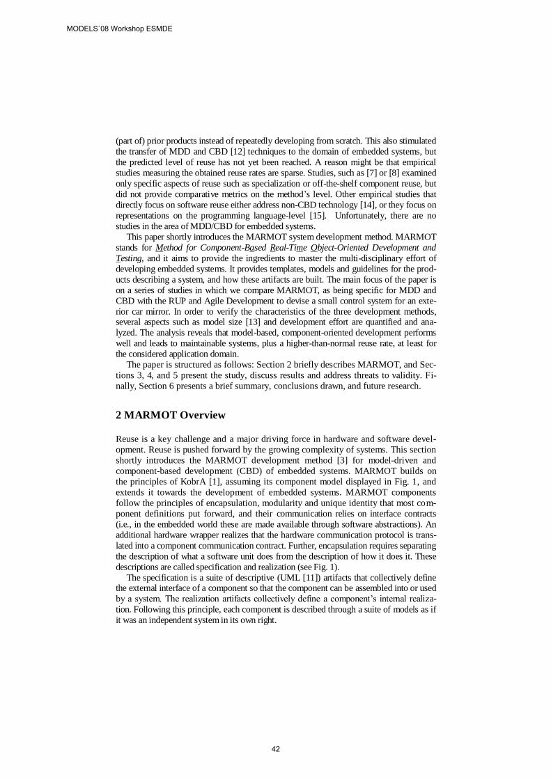
(part of) prior products instead of repeatedly developing from scratch. This also stimulated
the transfer of MDD and CBD [12] techniques to the domain of embedded systems, but
the predicted level of reuse has not yet been reached. A reason might be that empirical
studies measuring the obtained reuse rates are sparse. Studies, such as [7] or [8] examined
only specific aspects of reuse such as specialization or off-the-shelf component reuse, but
did not provide comparative metrics on the method’s level. Other empirical studies that
directly focus on software reuse either address non-CBD technology [14], or they focus on
representations on the programming language-level [15]. Unfortunately, there are no
studies in the area of MDD/CBD for embedded systems.
This paper shortly introduces the MARMOT system development method. MARMOT
stands for Method for Component-Based Real-Time Object-Oriented Development and
Testing, and it aims to provide the ingredients to master the multi-disciplinary effort of
developing embedded systems. It provides templates, models and guidelines for the prod-
ucts describing a system, and how these artifacts are built. The main focus of the paper is
on a series of studies in which we compare MARMOT, as being specific for MDD and
CBD with the RUP and Agile Development to devise a small control system for an exte-
rior car mirror. In order to verify the characteristics of the three development methods, several aspects such as model size [13] and development effort are quantified and ana-
lyzed. The analysis reveals that model-based, component-oriented development performs
well and leads to maintainable systems, plus a higher-than-normal reuse rate, at least for
the considered application domain.
The paper is structured as follows: Section 2 briefly describes MARMOT, and Sec-
tions 3, 4, and 5 present the study, discuss results and address threats to validity. Fi-
nally, Section 6 presents a brief summary, conclusions drawn, and future research.
2 MARMOT Overview
Reuse is a key challenge and a major driving force in hardware and software devel-
opment. Reuse is pushed forward by the growing complexity of systems. This section
shortly introduces the MARMOT development method [3] for model-driven and
component-based development (CBD) of embedded systems. MARMOT builds on
the principles of KobrA [1], assuming its component model displayed in Fig. 1, and
extends it towards the development of embedded systems. MARMOT components
follow the principles of encapsulation, modularity and unique identity that most com-
ponent definitions put forward, and their communication relies on interface contracts
(i.e., in the embedded world these are made available through software abstractions). An
additional hardware wrapper realizes that the hardware communication protocol is trans-
lated into a component communication contract. Further, encapsulation requires separating
the description of what a software unit does from the description of how it does it. These
descriptions are called specification and realization (see Fig. 1).
The specification is a suite of descriptive (UML [11]) artifacts that collectively define the external interface of a component so that the component can be assembled into or used
by a system. The realization artifacts collectively define a component’s internal realiza-
tion. Following this principle, each component is described through a suite of models as if
it was an independent system in its own right.
MODELS`08 Workshop ESMDE
42
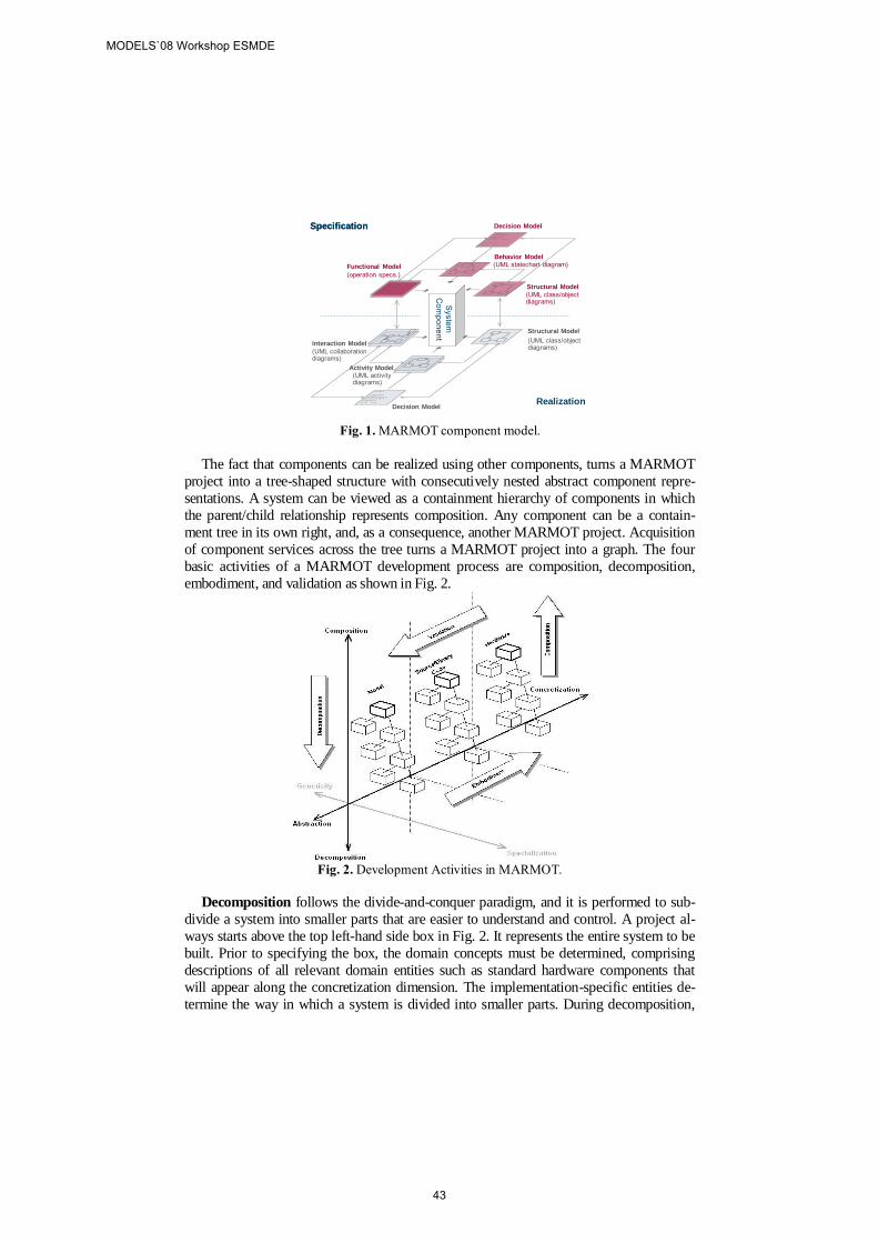
Fig. 1. MARMOT component model.
The fact that components can be realized using other components, turns a MARMOT
project into a tree-shaped structure with consecutively nested abstract component repre-
sentations. A system can be viewed as a containment hierarchy of components in which
the parent/child relationship represents composition. Any component can be a contain-
ment tree in its own right, and, as a consequence, another MARMOT project. Acquisition
of component services across the tree turns a MARMOT project into a graph. The four
basic activities of a MARMOT development process are composition, decomposition,
embodiment, and validation as shown in Fig. 2.
Fig. 2. Development Activities in MARMOT.
Decomposition follows the divide-and-conquer paradigm, and it is performed to sub-
divide a system into smaller parts that are easier to understand and control. A project al-
ways starts above the top left-hand side box in Fig. 2. It represents the entire system to be
built. Prior to specifying the box, the domain concepts must be determined, comprising
descriptions of all relevant domain entities such as standard hardware components that
will appear along the concretization dimension. The implementation-specific entities de-
termine the way in which a system is divided into smaller parts. During decomposition,
Structural Model
(UML class/object diagrams)
Functional Model
(operation specs.)
Behavior Model
(UML statechart diagram)
Decision ModelSpecification
Realization
Structural Model
(UML class/object diagrams)
Interaction Model
(UML collaboration diagrams)
Activity Model(UML activity diagrams)
Decision Model
Syste
mC
om
po
ne
nt
Specification
MODELS`08 Workshop ESMDE
43
newly identified logical parts are mapped to existing components, or the system is decom-
posed according to existing components. Whether these are hard- or software is not impor-
tant since all components are treated in a uniform way, as software abstractions.
Composition represents the opposite activity, which is performed when individual
components have been implemented or reused, and the system is put together. After
having implemented some of the boxes and having some others reused, the system
can be assembled according to the abstract model. The subordinate boxes with their
respective super-ordinate boxes have to be coordinated in a way that exactly follows
the component description standard introduced above.
Embodiment is concerned with the implementation of a system and a move towards
executable representations. It turns the abstract system (i.e., models) into concrete
representations that can be executed. MARMOT uses refinement and translation pat-
terns for doing these transformations. MARMOT supports the generation of code
skeletons and can thus be regarded as a semi-automatic approach.
Validation checks whether the concrete representations are in line with the abstract
ones. It is carried out in order to check whether the concrete composition of the em-
bedded system corresponds to its abstract description.
3 Description of the Study
In general, empirical studies in software engineering are used to evaluate whether a “new”
technique is superior to other techniques concerning a specific problem or property. The
objective of this study is to compare the effects of MARMOT concerning reuse in embedded system development to other approaches such as the Unified process and agile development.
The study was organized in three runs (i.e., one run per methodology). All runs fol-
lowed the same schema. Based on an existing system, documentation subjects performed
a number of small projects. These covered typical project situations such as maintenance,
ports to another platform, variant development, and reuse in a larger context. The first run
applied MARMOT. The second run repeated all projects but used a variation of the Uni-
fied process, specifically adapted for embedded system development. The third run, apply-
ing an agile approach, was used to validate that modeling has a major impact and to rule
out that reuse effects can solely be obtained at the code level. Metrics were collected in all
runs and were analyzed in order to evaluate the respective research questions.
3.1. RESEARCH APPROACH
Introducing MDD and CBD in an organization is generally a slow process. An organiza-
tion will start with some reusable components, and eventually build a component reposito-
ry. But they are unsure about the return on investment gained by initial component devel-
opment plus reuse for a real system, and the impact of the acquired technologies on quality and time-to-market. This is the motivation for performing the study and asking questions
on the performance of these techniques.
Research Questions. Several factors concerning the development process and its
resulting product are recorded throughout the study in order to gain knowledge about
using MDD and CBD for the development of small embedded systems. The research
MODELS`08 Workshop ESMDE
44
questions of the case-study focus on two key sets of properties of MDD in the context of
component-oriented development. The first set of questions (Q1-Q4) lead to an
understanding of basic and/or general properties of the embedded system development
approach: Q1: Which process was used to develop the system? Each run of the study used a
different development approach (i.e., MARMOT, Unified Process, and Agile). These
are compared in terms of different quality attributes of the resulting systems.
Q2: Which types of diagrams have been used? Are all UML diagram types required,
or is there possibly a specific subset sufficient for this domain? Q3: How were models transferred to source code? Developers typically work in a proce-
dural setting that impedes the manual transformation of UML concepts into C [10].
Q4: How was reuse applied and organized? Reuse is central to MDD with respect to
quality, time-to-market, and effort, but reuse must be built into the process, it does not
come as a by-product (i.e., components have to be developed for reuse).
The second set of questions (Q5-Q9) deals with the resulting product of the applied
approach (i.e., with respect to code size, defect density, and time-to-market).
Q5: What is the model-size of the systems? MDD is often believed to create a large
overhead of models, even for small projects. Within the study, model size follows the
metrics as defined in [13].
Q6: What is the defect density of the code?
Q7: How long did it take to develop the systems and how is this effort distributed over the requirements, design, implementation, and test phases? Effort saving is one
promise of MDD and CBD [12], though, it does not occur immediately (i.e., in the
first project), but in follow-up projects. Effort is measured for all development phases.
Q8: What is the size of the resulting systems? Memory is a sparse resource and pro-
gram size extremely important. MDD for embedded systems will only be successful if
the resulting code size, obtained from the models, is small.
Q9: How much reuse did take place? Reuse is central for MDD and CBD and it must
be seen as an upfront investment paying off in many projects. Reuse must be ex-
amined between projects and not within a project.
Research Procedure. MDD and CBD promise efficient reuse and short time-to-
market, even for embedded systems. Since it is expected that the benefits of MDD
and CBD are only visible during follow-up projects [5], an initial system was
specified and used as basis for all runs. The follow-ups then were: R1/R2 Ports to different hardware platforms while keeping functionality. Ports were
performed within the family (i.e., ATMega32) and to a different processor family (i.e.,
PICF). Implementing a port within the same family might be automated at the code-
level, whereas, a port to a different family might affect the models.
R3/R4 Evolving system requirements by (1) removing the recall position functionali-
ty, and (2) adding a defreeze/defog function with a humidity sensor and a heater.
R5 The mirror system was reused in a door control unit that incorporates the control
of the mirror, power windows, and door illumination.
MODELS`08 Workshop ESMDE
45
3.2. PREPARATION
Methodologies. The study examines the effects of three different development me-
thods on software reuse and related quality factors. In the first run, we used the
MARMOT method that is intended to provide all the ingredients to master the multi-
disciplinary effort of developing component-based embedded systems. In the second
run we followed an adapted version of the Unified Process for embedded system devel-
opment [4] (i.e., RUP SE). RUP SE includes an architecture model framework that sup-
ports different perspectives. A distinguishing characteristic of RUP SE is that the compo-
nents regarding the perspectives are jointly derived in increasing specificity from the over-
all system requirements. In the third run, an agile process (based on Extreme Pro-
gramming) [9], adapted towards embedded software development, was used.
Subjects of the study were graduate students from the Department of Computer Science
at the University of Kaiserslautern (1st run) and the School of IT at the International
University (2nd
and 3rd run). All students, 45 in total (3 per team/project), were enrolled
in a Software Engineering class, in which they were taught principles, OO methods,
modeling, and embedded system development. Lectures were supplemented by practical
sessions in which students had the opportunity to make use of what they had learned. At
the beginning of the course, subjects were informed that a series of practical exercises
were planned. Subjects knew that data would be collected and that an analysis would be
performed, but were unaware of the hypotheses that were being tested. To further con-
trol for learning and fatigue effects and differences between subjects, random assign-
ment to the development teams was performed. As the number of subjects was known
before running the studies it was a simple procedure to create teams of equivalent size.
Metrics. All projects were organized according to typical reuse situations in compo-
nent-based development, and a number of measurements were performed to answer
the research questions of the previous sub-section:
Model-size is measured using the absolute and relative size measures proposed in [13].
Relative size measures (i.e., ratios of absolute measures) are used to address UMLs multi-
diagram structure and to deal with completeness [13]. Absolute measures used are: the
number of classes in a model (NCM), number of components in a model (NCOM), num-
ber of diagrams (ND), and LOC, which are sufficient as complexity metrics for the simple components used in this case. NCOM describes the number of hardware/software compo-
nents, while NCM is represents the number of software components. These metrics are
comparable to metrics such as McCabe’s cyclomatic complexity for estimating the
size/nesting of a system. Code-size is measured in normalized LOC. System size is meas-
ured in KBytes of the binary code. All systems were compiled using size optimization.
The amount of reused elements is described as the proportion of the system which can
be reused without any changes or with small adaptations (i.e., configuration but no model
change). Measures are taken at the model and code level.
Defect density is measured in defects per 100 LOC, whereby defects where collected
via inspection and testing activities.
Development effort and its distribution over development phases are measured as
development time (hours) collected by daily effort sheets.
Materials. The study uses a car-mirror control system that moves a mirror horizontally
and vertically into the desired position. Positions can be stored/recalled to support driver
profiles. The simplified version of this study controls two servos via potentiometers, and
MODELS`08 Workshop ESMDE
46
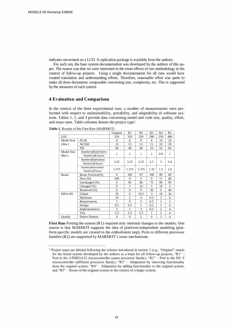
indicates movement on a LCD. A replication package is available from the authors.
For each run, the base system documentation was developed by the authors of this pa-
per. The reason was that we were interested in the reuse effects of one methodology in the
context of follow-up projects. Using a single documentation for all runs would have
created translation and understanding efforts. Therefore, reasonable effort was spent to
make all three documents comparable concerning size, complexity, etc. This is supported
by the measures of each system.
4 Evaluation and Comparison
In the context of the three experimental runs, a number of measurements were per-
formed with respect to maintainability, portability, and adaptability of software sys-
tems. Tables 1, 2, and 3 provide data concerning model and code size, quality, effort,
and reuse rates. Table columns denote the project type1.
Table 1. Results of the First Run (MARMOT) Original R1 R2 R3 R4 R5
LOC 310 310 320 280 350 490
Model Size
(Abs.)
NCM 8 8 8 6 10 10
NCOM 15 15 15 11 19 29
ND 46 46 46 33 52 64
Model Size
(Rel.) 1 1 1 1 0.8 1
3.25 3.25 3.25 2.5 3 3.4
1.375 1.375 1.375 1.33 1.3 1.6
Reuse Reuse Fraction(%) 0 100 97 100 89 60
New (%) 100 0 3 0 11 40
Unchanged (%) 0 95 86 75 90 95
Changed (%) 0 5 14 5 10 5
Removed (%) 0 0 0 20 0 40
Effort (h) Global 26 6 10.5 3 10 24
Hardware 10 2 4 0.5 2 8
Requirements 1 0 0 0.5 1 2
Design 9.5 0.5 1 0.5 5 6
Implementation 3 1 3 0.5 2 4
Test 2.5 2.5 2.5 1 2 4
Quality Defect Density 9 0 2 0 3 4
First Run Porting the system (R1) required only minimal changes to the models. One reason is that MARMOT supports the idea of platform-independent modeling (plat-
form specific models are created in the embodiment step). Ports to different processor
families (R2) are supported by MARMOT’s reuse mechanisms.
1 Project types are labeled following the scheme introduced in section 3 (e.g., “Original” stands
for the initial system developed by the authors as a basis for all follow-up projects, “R1” – Port to the ATMEGA32 microcontroller (same processor family), “R2” – Port to the PIC F
microcontroller (different processor family), “R3“ – Adaptation by removing functionality
from the original system, “R4” – Adaptation by adding functionality to the original system,
and “R5” – Reuse of the original system in the context of a larger system.
assesNumberofCl
ateChartsNumberofSt
assesNumberofCl
erationsNumberofOp
assesNumberofCl
sociationsNumberofAs
MODELS`08 Workshop ESMDE
47
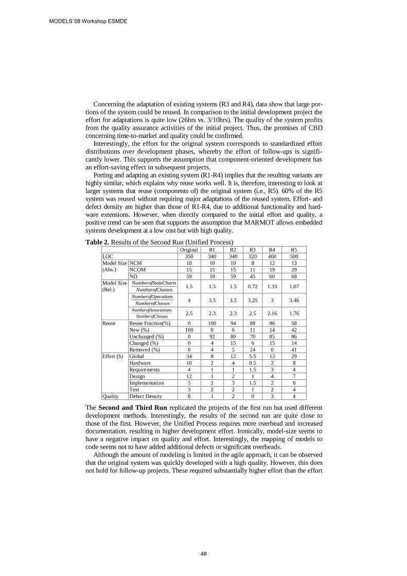
Concerning the adaptation of existing systems (R3 and R4), data show that large por-
tions of the system could be reused. In comparison to the initial development project the
effort for adaptations is quite low (26hrs vs. 3/10hrs). The quality of the system profits
from the quality assurance activities of the initial project. Thus, the promises of CBD
concerning time-to-market and quality could be confirmed.
Interestingly, the effort for the original system corresponds to standardized effort
distributions over development phases, whereby the effort of follow-ups is signifi-
cantly lower. This supports the assumption that component-oriented development has
an effort-saving effect in subsequent projects.
Porting and adapting an existing system (R1-R4) implies that the resulting variants are
highly similar, which explains why reuse works well. It is, therefore, interesting to look at
larger systems that reuse (components of) the original system (i.e., R5). 60% of the R5
system was reused without requiring major adaptations of the reused system. Effort- and
defect density are higher than those of R1-R4, due to additional functionality and hard-
ware extensions. However, when directly compared to the initial effort and quality, a
positive trend can be seen that supports the assumption that MARMOT allows embedded
systems development at a low cost but with high quality.
Table 2. Results of the Second Run (Unified Process) Original R1 R2 R3 R4 R5
LOC 350 340 340 320 400 500
Model Size
(Abs.)
NCM 10 10 10 8 12 13
NCOM 15 15 15 11 19 29
ND 59 59 59 45 60 68
Model Size
(Rel.) 1.5 1.5 1.5 0.72 1.33 1.07
4 3.5 3.5 3.25 3 3.46
2.5 2.3 2.3 2.5 2.16 1.76
Reuse Reuse Fraction(%) 0 100 94 88 86 58
New (%) 100 0 6 11 14 42
Unchanged (%) 0 92 80 70 85 86
Changed (%) 0 4 15 6 15 14
Removed (%) 0 4 5 24 0 41
Effort (h) Global 34 8 12 5.5 13 29
Hardware 10 2 4 0.5 2 8
Requirements 4 1 1 1.5 3 4
Design 12 1 2 1 4 7
Implementation 5 2 3 1.5 2 6
Test 3 2 2 1 2 4
Quality Defect Density 8 1 2 0 3 4
The Second and Third Run replicated the projects of the first run but used different
development methods. Interestingly, the results of the second run are quite close to
those of the first. However, the Unified Process requires more overhead and increased documentation, resulting in higher development effort. Ironically, model-size seems to
have a negative impact on quality and effort. Interestingly, the mapping of models to
code seems not to have added additional defects or significant overheads.
Although the amount of modeling is limited in the agile approach, it can be observed
that the original system was quickly developed with a high quality. However, this does
not hold for follow-up projects. These required substantially higher effort than the effort
assesNumberofCl
ateChartsNumberofSt
assesNumberofCl
erationsNumberofOp
assesNumberofCl
sociationsNumberofAs
MODELS`08 Workshop ESMDE
48

required for runs 1 and 2. A reason might be that follow-ups were not performed by the
developers of the original system. Due to missing documentation and abstractions, reuse
rates are low. In contrast, the source-code is of a good quality.
Table 3. Results of the Third Run (Agile) Original R1 R2 R3 R4 R5
LOC 280 290 340 300 330 550
Model
Size
(Abs.)
NCM 14 15 15 13 17 26
NCOM 5 5 5 4 7 12
ND 3 3 3 3 3 3
Model
Size
(Rel.)
0 0 0 0 0 0
3.21 3.3 3.3 3.15 3.23 4.19
3.5 3.3 3.3 3.46 3.17 2.57
Reuse Reuse Fraction(%) 0 95 93 93 45 25
New (%) 100 5 7 7 55 75
Unchanged (%) 0 85 75 40 54 85
Changed (%) 0 14 15 40 36 10
Removed (%) 0 1 10 20 10 5
Effort (h) Global 18 5 11.5 6 13.5 37
Hardware 6 2 4 1 2 8
Requirements 0.5 0 0 0.5 1 1
Design 2 0 0 1 1.5 3
Implementation 7 2 5 2 6 18
Test 2.5 1 2.5 1.5 3 7
Quality Defect Density 7 0 2 1 5 7
5 Threats to Validity
The authors view this study as exploratory. Thus, threats limit generalization of this
research, but do not prevent the results from being used in further studies.
Construct Validity. Reuse is a difficult concept to measure. In the context of this paper
it is argued that the defined metrics are intuitively reasonable measures. Of course, there
are several other dimensions of each concept. However, in a single controlled study it is
unlikely that all the different dimensions of a concept can be captured.
Internal Validity. A maturation effect is caused by subjects learning as the study
proceeds. The threat to this study is subjects learned enough from single runs to bias
their performance in the following ones. An instrumentation effect may result from differences in the materials which may have caused differences in the results. This
threat was addressed by keeping the differences to those caused by the applied me-
thod. This is supported by the data points as presented in table 1, 2, and 3. Another
threat might be the fact that the studies were conducted at different institutes.
External Validity. The subjects were students and are, therefore, unlikely to be represent-
ative of software professionals. However, the results can be useful in an industrial context
for the following reasons: Industrial employees often do not have more experience than
students when it comes to applying MDD. Furthermore, laboratory settings allow the
investigation of a larger number of hypotheses at a lower cost than field studies. Hypo-
theses supported in the laboratory setting can be tested further in industrial settings.
assesNumberofCl
ateChartsNumberofSt
assesNumberofCl
erationsNumberofOp
assesNumberofCl
sociationsNumberofAs
MODELS`08 Workshop ESMDE
49
6 Summary and Conclusions
The growing interest in the Unified Modeling Language provides a unique opportunity
to increase the amount of modeling work in software development, and to elevate quali-
ty standards. UML 2.0 promises new ways to apply object/component-oriented and model-based development techniques in embedded systems engineering. However, this
chance will be lost, if developers are not given effective and practical means for han-
dling the complexity of such systems, and guidelines for applying them systematically.
This paper shortly introduced the MARMOT approach that supports the compo-
nent-oriented and model-based development of embedded software systems. A series
of studies was described that were defined to empirically validate the effects of
MARMOT on aspects such as reuse or quality in comparison to the Unified Process
and an agile approach. The results indicate that by using MDD and CBD for embed-
ded system development will have a positive impact on reuse, effort, and quality.
However, similar to product-line engineering projects, CBD requires an upfront in-
vestment. Therefore, all results have to be viewed as initial. This has led to the plan-
ning of a larger controlled experiment to obtain more objective data.
References
[1] Atkinson, C., Bayer, J., Bunse, C., and others. Component-Based Product-Line Engineering
with UML, Addison-Wesley, UK, 2001.
[2] Bunse, C., Gross, H.-G., Peper, C., Applying a Model-based Approach for Embedded Sys-tem Development, 33rd SEAA, Lübeck, Germany, 2007.
[3] Bunse, C., Gross, H.-G., Unifying Hardware and Software Components for Embedded
System Development, In: Architecting Systems with Trustworthy Components, Reussner,
Staffort, Szyperski (Eds), Lecture Notes in Computer Science, Vol. 3938, Springer, 2006. [4] Cantor, M., Rational Unified Process for Systems Engineering, the Rational Edge e-Zine,
2003, http://www.therationaledge.com/content/aug_03/f_rupse_mc.jsp.
[5] Crnkovic, I., Larsson, M. (Eds.), Building Reliable Component-Based Software Systems,
Artech House, 2002. [6] Douglass, B.P., Real-Time Design Patterns, Addison-Wesley, 2003.
[7] Briand, L.C., Bunse, C., Daly, J.W., A Controlled Experiment for Evaluating Quality
Guidelines on the Maintainability of Object-Oriented Designs, IEEE TSE, 27(6), 2001
[8] Li, J., Conradi, R., Slyngstad, O.P.N., Torchiano, M., Morisio, M., Bunse, C., A State-of-the-Practice Survey of Risk Management in Development with Off-the-Shelf Software,
IEEE Transaction on Software Engineering, 34(2), 2008
[9] Hruschka, P., Rupp, C., Agile SW-Entwicklung für Embedded Real-Time Systems mit
UML, Hanser, 2002. [10] Marwedel, P., Embedded System Design, (Updated Version), Springer, 2006.
[11] Object Management Group, UML Infrastructure and Superstructure, V2.1.2, 2007
[12] Szyperski, J., Component Software. Beyond OOP, Addison-Wesley, 2002
[13] Lange, C.F., Model Size Matters, Workshop on Model Size Metrics, 2006 (co-located with the ACM/IEEE MoDELS/UML Conference); October, 2006.
[14] Burkhard, J-M., Detienne, F., An Empirical Study of Software Reuse By Experts in Ob-
ject-Oriented Design, INTERACT'95, Lillehammer Norway, June 27-29 1995
[15] Lee, N-Y., Litecky, C.R., An Empirical Study of Software Reuse with Special Attention to ADA, IEEE Transaction on Software Engineering, 23(9), 1997
MODELS`08 Workshop ESMDE
50
Towards Quality-Driven Model Transformations: A Replication Study
Emilio Insfran1, José Ángel Carsí1, Silvia Abrahão1, Marcela Genero2, Isidro Ramos1, Mario Piattini2
1 ISSI Group, Department of Information Systems and Computation
Universidad Politécnica de Valencia Camino de Vera, s/n, 46022, Valencia, Spain
{einsfran, pcarsi, sabrahao, iramos}@dsic.upv.es
2 ALARCOS Group, Department of Information Systems and Technologies, University of Castilla-La-Mancha
Paseo de la Universidad Nº 4, 13071, Ciudad Real, Spain {Marcela.Genero, Mario.Piattini}@uclm.es
Abstract. Commonly, there are several ways to transform a source model into a target model. These alternative target models may have the same functionality but can differ in their quality attributes. One of the key challenges of an automated transformation process is to identify the transformations that will produce a target model with the desired quality attributes. In this paper, we present a replica of a controlled experiment to investigate the selection of alternative transformations to obtain UML class models from a Requirements Model. This is a concrete instantiation of a wider domain-independent approach for quality-driven model transformation. Specifically, we focus on a set of transformations related to structural relationships between classes (association, aggregation and association class) and the understandability quality attribute. Although, some results could be foreseen even by a superficial analysis of the alternatives, the goal of this work is to use experimentation to gather empirical evidence about which alternative transformation produces the UML class model that is the easiest to understand. The empirical results support the original results showing that there is a tendency to favor the use of association relationships to drive these transformations when understandability is chosen.
Keywords: Model transformations, MDA, Software Quality, Requirements, UML class model, Empirical Software Engineering.
1 Introduction
Model-Driven Architecture (MDA) is an emerging approach to software development. It promotes the use of models and model transformations as the primary artefacts to be built and maintained. In essence, an MDA development process transforms a Platform-Independent Model (PIM) into one or more Platform-Specific Models (PSM), which are then transformed into code (Code Model – CM). Therefore,
MODELS`08 Workshop ESMDE
51
2
in this context, a model is no longer simply a means for describing software, but rather an essential piece of the software development process. Consequently, the quality of the models built throughout this process is of great significance since these models will determine the quality of the software product that is finally deployed.
Usually, in an MDA development process there are several ways to transform a source model into a target model. Alternative target models may have the same functionality but differ in their quality attributes. One of the key challenges for an automated transformation process is to identify which transformations will produce a target model with the desired quality attributes (e.g., understandability, modifiability).
In the last few years, some approaches that deal with quality in Model-Driven Engineering (MDE) have been proposed [15] [14] [12] [13] [8] [9]. One disadvantage of these approaches is that the practical applicability of model transformations is often reported based on the intuition of the researcher. As pointed out by Czarnecki and Helsen [4], there is a lack of controlled experiments to fully validate the observations made by the researchers in the field of MDE. Therefore, more systematic approaches to ensure quality in MDE processes are needed.
In this paper, we present a replica of a controlled experiment to investigate the selection of alternative transformations to obtain UML class models from a Requirements Model [5] [6]. This work is part of a project on quality-driven model transformations whose overall goal is the definition of a quality metamodel to drive the selection of alternative model transformations according to different quality attributes.
Specifically, we focus on a sub-set of transformations that are related to structural relationships between classes (association, aggregation, and association class) and the ‘understandability’ quality attribute. These transformations have been selected because the determination of structural relationships has a great impact on the UML class model. Understandability has been selected since it is recognized as the main quality attribute that influences maintainability. A UML class model must be understood before any desired change to it can be identified, designed or implemented.
The goal of the experimentation is to gather empirical evidence about which alternative transformation produces the UML class model that is the easiest to understand. The empirical evaluation of the best transformation is particularly important when the transformations are automatically applied, which is the main reason for adopting MDA [11].
This paper is organized as follows. Section 2 gives an overview of our approach to transform a Requirements Model into UML class models. This section also shows the analysis of alternative model transformations. Section 3 describes the design of the original experiment and its replica to empirically validate the selection of alternative transformations with regard to the understandability. Section 4 presents the data analysis and the interpretation of the results. Finally, section 5 presents our conclusions and future work.
MODELS`08 Workshop ESMDE
52
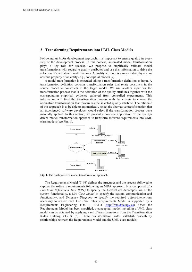
3
2 Transforming Requirements into UML Class Models
Following an MDA development approach, it is important to ensure quality in every step of the development process. In this context, automated model transformation plays a key role for success. We propose to empirically validate model transformations with regard to quality attributes and use this information to drive the selection of alternative transformations. A quality attribute is a measurable physical or abstract property of an entity (e.g., conceptual model) [7].
A model transformation is executed taking a transformation definition as input. A transformation definition contains transformation rules that relate constructs in the source model to constructs in the target model. We use another input for the transformation process that is the definition of the quality attributes together with the corresponding empirical evidence gathered from controlled experiments. This information will feed the transformation process with the criteria to choose the alternative transformation that maximizes the selected quality attribute. The rationale of this approach is to be able to automatically select the alternative transformation that an experienced software developer would select if the transformation process were manually applied. In this section, we present a concrete application of the quality-driven model transformation approach to transform software requirements into UML class models (see Fig. 1).
Fig. 1. The quality-driven model transformation approach
The Requirements Model [5] [6] defines the structures and the process followed to capture the software requirements following an MDA approach. It is composed of a Functions Refinement Tree (FRT) to specify the hierarchical decomposition of the system functionality, a Use Case Model to specify the system communication and functionality, and Sequence Diagrams to specify the required object-interactions necessary to realize each Use Case. This Requirements Model is supported by a Requirements Engineering TOol – RETO (http://reto.dsic.upv.es). Once the Requirements Model has been specified, a conceptual model including a UML class model can be obtained by applying a set of transformations from the Transformation Rules Catalog (TRC) [5]. These transformation rules establish traceability relationships between the Requirements Model and the UML class models.
MODELS`08 Workshop ESMDE
53
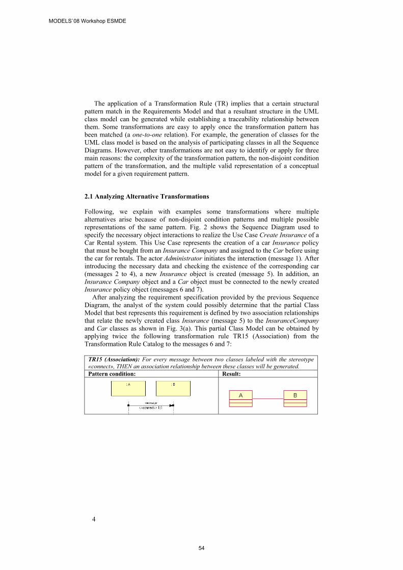
4
The application of a Transformation Rule (TR) implies that a certain structural pattern match in the Requirements Model and that a resultant structure in the UML class model can be generated while establishing a traceability relationship between them. Some transformations are easy to apply once the transformation pattern has been matched (a one-to-one relation). For example, the generation of classes for the UML class model is based on the analysis of participating classes in all the Sequence Diagrams. However, other transformations are not easy to identify or apply for three main reasons: the complexity of the transformation pattern, the non-disjoint condition pattern of the transformation, and the multiple valid representation of a conceptual model for a given requirement pattern.
2.1 Analyzing Alternative Transformations
Following, we explain with examples some transformations where multiple alternatives arise because of non-disjoint condition patterns and multiple possible representations of the same pattern. Fig. 2 shows the Sequence Diagram used to specify the necessary object interactions to realize the Use Case Create Insurance of a Car Rental system. This Use Case represents the creation of a car Insurance policy that must be bought from an Insurance Company and assigned to the Car before using the car for rentals. The actor Administrator initiates the interaction (message 1). After introducing the necessary data and checking the existence of the corresponding car (messages 2 to 4), a new Insurance object is created (message 5). In addition, an Insurance Company object and a Car object must be connected to the newly created Insurance policy object (messages 6 and 7).
After analyzing the requirement specification provided by the previous Sequence Diagram, the analyst of the system could possibly determine that the partial Class Model that best represents this requirement is defined by two association relationships that relate the newly created class Insurance (message 5) to the InsuranceCompany and Car classes as shown in Fig. 3(a). This partial Class Model can be obtained by applying twice the following transformation rule TR15 (Association) from the Transformation Rule Catalog to the messages 6 and 7:
TR15 (Association): For every message between two classes labeled with the stereotype «connect», THEN an association relationship between these classes will be generated. Pattern condition: Result:
MODELS`08 Workshop ESMDE
54
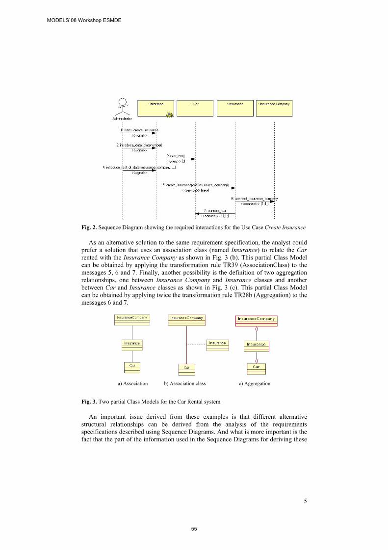
5
Fig. 2. Sequence Diagram showing the required interactions for the Use Case Create Insurance
As an alternative solution to the same requirement specification, the analyst could prefer a solution that uses an association class (named Insurance) to relate the Car rented with the Insurance Company as shown in Fig. 3 (b). This partial Class Model can be obtained by applying the transformation rule TR39 (AssociationClass) to the messages 5, 6 and 7. Finally, another possibility is the definition of two aggregation relationships, one between Insurance Company and Insurance classes and another between Car and Insurance classes as shown in Fig. 3 (c). This partial Class Model can be obtained by applying twice the transformation rule TR28b (Aggregation) to the messages 6 and 7.
a) Association b) Association class c) Aggregation
Fig. 3. Two partial Class Models for the Car Rental system
An important issue derived from these examples is that different alternative structural relationships can be derived from the analysis of the requirements specifications described using Sequence Diagrams. And what is more important is the fact that the part of the information used in the Sequence Diagrams for deriving these
MODELS`08 Workshop ESMDE
55
6
structural relationships follows the same pattern: a message with the stereotype new, followed by two messages with a stereotype connect.
In the examples, we have shown that TR15, TR39, or TR28b transformation rules could be applied, depending on the interpretation of the analyst if the transformation process is performed manually. In an automated transformation process, the information provided by the stereotyped Sequence Diagrams is not sufficient to automatically determine which structural relationship of a Class Model best realizes the specified requirement. Because these alternatives exist, it is the human analyst who should decide which alternative better represent a solution in the corresponding problem domain. In this work, considering that alternatives exist, we use controlled experiments to discover which alternative transformation maximizes a given quality attribute of the resulting target model (e.g., understandability).
3 A Controlled Experiment and its Replica
In a previous work [1], we presented a controlled experiment to determine which of the transformation rules for structural relationships: association (A1), aggregation (A2), or association class (A3), obtained the easiest to understand UML class model. The results show a slight tendency to favor the transformations related to associations (A1). However, as Basili et al. [2] suggested relevant and credible results can only be obtained by replicating the experiments. In other words, single studies rarely provide definitive answers. Therefore, we carried out an internal strict replication (changing only the subjects) to corroborate the findings. To provide an overall view of the experimentation, we explain both the original experiment and the replica.
3.1 Planning
The participants in the original experiment were 39 fourth-year students in Computer Science at the Universidad Politécnica de Valencia, who were taking part in the second Software Engineering course. We took a “convenience sample” (i.e., all the students in the class). The subjects had six month of experience in modeling with UML and three years of experience in the OO paradigm. The subjects that participated in the replica were a different group of 37 students from the same course.
The independent variables for the experiments were the transformation rules for structural relationships between classes (A1, A2 and A3). The dependent variable was understandability. The experimental material and tasks consisted of: • 9 Sequence Diagrams from three different case studies (a car rental system, a
hotel management system, and a singer contest system), with 3 UML class models each. These were obtained by applying the alternative transformation rules. The material used is available at: www.dsic.upv.es/~einsfran/experiment.
• Each Sequence Diagram had a questionnaire attached consisting of 6 Yes/No questions to test the subjects’ understanding of the Sequence Diagrams. The effectiveness of the subjects in answering the questionnaires (number of correct
MODELS`08 Workshop ESMDE
56
7
answers by number of answers) was used to exclude those observations that did not fulfill a minimum level of quality.
• Each of the three UML class models had a questionnaire attached (with 6 questions) for assessing which UML class model was best understood by the subjects. In addition, the subjects had to write down the starting and ending times for completing the questionnaires. For this purpose we used a wall clock. From this understanding task, we obtained three measures for understandability: Understandability Time, which reflects the time, in seconds, that the subjects spent answering each questionnaire (calculated by the difference between the ending time and the starting time). Each subject completed 4 questionnaires detailing 3 alternatives (A1, A2 and A3). Three understandability time measures (A1Time, A2Time and A3Time) were obtained. Effectiveness, which reflects the correctness of the answers (number of correct answers by number of answers). Three understandability effectiveness measures (A2Effec, A2Effec and A3Effec) were obtained. Efficiency, which reflects the correctness of the answers by time (number of correct answers by understandability time). Three measures for understandability efficiency (A2Effic, A2Effic and A3Effic) were obtained.
• The final task of each test asked the subjects which of the three alternative UML class models best reflected the problem modeled in the Sequence Diagram. It is a subjective measure (Alternative Selected) based on the subjects’ perception.
The following hypotheses were formulated: • H10: The use of different alternative transformations does not affect the
Understandability Time (A1Time, A2Time and A3Time). H11=¬H10 • H20: The use of different alternative transformations does not affect the
Understandability Effectiveness (A1Effec, A2Effec and A3Effec). H21=¬H20 • H30: The use of different alternative transformations does not affect the
Understandability Efficiency (A1Effic, A2Effic and A3Effic). H31=¬H30 • H40: There is no correlation between the Alternative Selected and the means of
objective Understandability variables (Understandability Time, Effectiveness, and Efficiency). H41= ¬H40
We selected a balanced within-subject design, i.e., each subject received the same experimental material.
3.2 Execution
Both the original experiment and the replica started with an introductory session in which we reviewed the main concepts of the Requirements Model (e.g., the notation of Sequence Diagrams). The goal of the experiment was not disclosed to the subjects. Then, we showed an example of the experimental material, which was similar to the material they would use during the execution of the experiment.
Each subject was assigned all the material, with the nine tests (balanced within-subject design). The models were assigned in different order to limit learning effects. We showed them how to develop the experimental tasks, and they had a maximum of two hours to complete all the tasks.
MODELS`08 Workshop ESMDE
57
8
After the experiment took place, we collected the experiment data, which consisted of a table of 351 rows (9 models x 39 subjects) and 9 columns (A1Time, A2Time, A3Time, A1Effec, A2Effec, A3Effec, A1Effic, A2Effec, A3Effec). The replica had the same structure, but with 331 rows (9 models x 37 subjects). In both samples, we performed a “data cleaning”, excluding the observations that were not complete because the subjects had not written down the time or because the subjects did not select the best alternative. All the questions were answered in each questionnaire, thereby assuring the completeness of the performed tasks. We also excluded the observations that had a value of effectiveness of 50% or less for each Sequence Diagram. We considered that if the level of correct answers was low in relation to the Sequence Diagram, the subjects had not really understood the model, and they would probably not perform well in the following tasks, so we discarded them. Therefore, the final data for testing the hypotheses were 325 observations for the original experiment and 293 for the replica.
4 Data Analysis and Interpretation
The following statistical analyses were performed to analyze the data: (1) a descriptive study was done to characterize the variables Alternative Selected, Understandability Time, Effectiveness, and Efficiency; (2) Hypotheses H1, H2, and H3 were tested using an ANOVA test with repeated measures; (3) Hypothesis H4 was tested using the Spearman correlation coefficient.
We used SPSS to carry out the data analyses presented in this study. The transformation most selected by the subjects was A1, i.e., the subjects believed that the use of associations obtained the easiest to understand UML class model. Association class (i.e., alternative A3) was the transformation that was least selected, which reveals that it could be the least appropriate transformation.
The descriptive statistics we carried out for Understandability Time, Effectiveness and Efficiency suggest the following: • Original Experiment. On average, the subjects spent less time performing the
tasks related to alternative A2; however, the difference with the others is not very significant (≈ 8 seconds for A1 and A3). The subjects were more effective and efficient performing the tasks related to alternative A1; however, the difference in effectiveness with the other alternatives is not very significant.
• Replica. The measures related to A1 have the best values, which means that, on average, the subjects spent less time and were more effective and more efficient performing the tasks related to the class model that was obtained via associations.
In summary, the descriptive statistics show a slight tendency in favor of A1, the transformation based on associations. Surprisingly, the difference between the minimum and maximum time values is significant. This may be due to the fact that the subjects were novice modelers.
To test the hypotheses presented in section 3.1, we carried out an ANOVA for repeated measures, which is the appropriate statistical test for analyzing the collected data [10]. Due to space constraints, we will briefly present the main findings obtained through the ANOVA for each data sample:
MODELS`08 Workshop ESMDE
58
9
• Original Experiment. We can reject hypotheses H10 (p = 0.0002), H20 (p = 0.0001), and H30 (p = 0.0005), with a significance level = 0.05. This means that the use of different alternative transformations really affects understandability time, effectiveness, and efficiency.
• Replica. We can reject H10 (p = 0.0028) and H20 (p = 0.0003), which means that the use of one alternative or another does not affect efficiency but does affect time and effectiveness when the subjects understand the class models.
When planning the experiment, we designed it in such a way as to alleviate the threats to the internal validity.
One limitation to the external validity (i.e., the generalization of the findings) of this study is the fact that the three alternative transformation rules cannot be applied simultaneously to all modeling situations. For instance, to establish an association class relationship (A3), at least one «service/new» message and two «connect» messages are needed in the source model. The goal of this experimentation was to gather empirical evidence for the specific case when the three alternative transformations could be applied to obtain a relationship between classes. We are aware that, more alternatives may be possible to represent structural relationships between classes. More experimentation is needed to validate these other combinations. Another limitation to the external validity might be the use of students as experimental subjects. However, the students who participated in the experiment can be considered to be representative of novice users of conceptual modeling approaches. To increase external validity, the current study needs to be replicated using experienced practitioners.
5 Conclusions and Future Work
This paper has presented an analysis of alternative model transformations and how controlled experiments can be used to provide useful information to guide the selection of transformations in an automated transformation process. In particular, we presented the results of an experiment to gather evidence about which alternative transformation produces the UML class model that is easiest to understand.
The main findings obtained from the experimentation are the following: (a) the transformation that was most selected in the original experiment and the replica was the association transformation (A1); (b) the results of the replica confirm the results of the original experiment for effectiveness. The subjects were more effective when they understood the class models with association relationships; (c) the fact that the hypothesis related to efficiency could not be confirmed in the replication has no great impact on our approach since the transformations are automatically executed in a Model Management framework (MOMENT) [3].
These results show that there is a slight tendency to favor the use of association relationships as part of an automated transformation process. A possible reason for this could be that this relationship has less semantic strength than the other kinds of relationships. When an aggregation relationship is chosen instead of an association relationship, analysts know that they are defining a part-of relationship. In the case of an association class, it is possible to represent almost the same relationship using two
MODELS`08 Workshop ESMDE
59
10
association relationships. Although the results obtained can be quite obvious the important point is the systematic approach presented to validate this ‘obvious’ results. That the association relationship is more understandable than the aggregation relationship or association classes is something that almost all the people can say but until this moment no one has the data to confirm that result but merely by intuition.
These preliminary results provided empirical evidence that can be further used to define a domain-independent quality metamodel to drive the execution of model transformations. Nevertheless, more replication is needed for building a body of knowledge. We plan to replicate this experiment with practitioners. Future work also includes the evaluation of the remaining transformations of the Transformation Rules Catalog taking into account other quality attributes (e.g., usability, modifiability).
Acknowledgments. This research is part of the META project TIN2006-15175-C05-05, the MECENAS project PBI06-0024, and the IDONEO project PAC08-0160-6141.
References
1. Abrahão, S., Genero, M., Insfran, E., Carsí, J.A., Ramos, I., Piattini, M.: Quality-Driven Model Transformations: From Requirements to UML Class Diagrams. In: Model-Driven Software Development: Integrating Quality Assurance, IGI Publishing, 2008.
2. Basili, V., Shull, F., Lanubile F.: Building Knowledge through Families of Experiments. In: IEEE Transactions on Software Engineering, 25(4): 435–437, 1999.
3. Boronat, A., Carsí, J.A., Ramos, I.: Algebraic Specification of a Model Transformation Engine. In: Fundamental Approaches to Software Engineering (FASE'06). ETAPS'06. Vienna, Austria, 2006, pp. 262–277.
4. Czarnecki, K., Helsen, S.: Feature-Based Survey of Model Transformation Approaches. In: IBM Systems Journal 45(3): 621–645, 2006.
5. Insfran, E.: A Requirements Engineering Approach for Object-Oriented Conceptual Modeling, PhD Thesis, DSIC, Valencia University of Technology, 2003.
6. Insfran, E., Pastor, O., Wieringa, R.: Requirements Engineering-Based Conceptual Modelling. In: Journal of Requirements Engineering 7(2): 61–72, 2002.
7. ISO, ISO/IEC 9126-1, (2001). Software Engineering – Product quality P1:Quality model. 8. Ivkovic, I., Kontogiannis K.: A Framework for Software Architecture Refactoring using
Model Transformations and Semantic Annotations. In: Conf. on Software Maintenance and Reengineering, 2006, pp. 135–144.
9. Kerhervé, B., Nguyen, K.K., Gerbé, O., Jaumard, B.: A Framework for Quality-Driven Delivery in Distributed Multimedia Systems. In: AICT/ICIW 2006, 2006, pp. 195–205.
10. Kirk, R.E.: Experimental design. Procedures for the behavioural sciences. Brooks/Cole Publishing Company, 1995.
11. Kontio, M.: Architectural Manifesto: The MDA adoption manual, (2005), Accessible at http://www-128.ibm.com/ developerworks/wireless/library/wi-arch17.html
12. Kurtev, I.: Adaptability of Model Transformations. PhD Thesis, Univ. of Twente, 2005. 13. Markovic, S., Baar, T.: Refactoring OCL Annotated UML Class Diagrams. In: 8th Int.
Conf. on Model Driven Engineering Languages and Systems, 2005, pp. 280–294. 14. Merilinna, J.: A Tool for Quality-Driven Architecture Model Transformation. In: Espoo,
VTT Electronics, VTT Publications, 2005. 15. Rottger, S., Zschaler, S.: Model-Driven Development for Non-functional Properties:
Refinement Through Model Transformation. In: The Unified Modelling Language (UML) Conference, LNCS Volume 3273, 2004, pp. 275–289.
MODELS`08 Workshop ESMDE
60
Analyzing the Influence of Certain Factors on the Acceptance of a Model-based Measurement Procedure in
Practice: An Empirical Study
Nelly Condori-Fernández, Oscar Pastor
Centro de Investigación en Métodos de Producción de Software Universidad Politécnica de Valencia, Camino de Vera s/n, 46022, Valencia.
{nelly, opastor}@pros.upv.es
Abstract. Full automatic software measurement from conceptual models is now accepted by academics, although take-up of these model-based measurement procedures in practice by software practitioners has been slow. To encourage acceptance in industry, an acceptance model for measurement procedures is proposed, identifying a set of factors that influence perceived usefulness and perceived ease of use when a user employs a measurement procedure. Analyzing the results of an empirical study carried out with software engineering academics, we find which factors have an influence on other factors. Using regression analysis, certain factors are identified that affect perceived usefulness and ease of use, and which in turn will affect intention to use.
1. Introduction
Although software measurement is recognized as a key element of engineering science, it has not yet been widely accepted in practice by software practitioners. The Software Engineering Measurement and Analysis (SEMA) group at the Software Engineering Institute (SEI) concluded from a series of explorative studies carried out from 2004-2005 [1] that there is still a significant gap between the current and desired state of software measurement. One of reasons for this is that there are no programs that use measures and empirical evidence to assess the practical relevance of such programs. Nowadays, with the appearance of the model-driven development process, several approaches have arisen which allow for full-automatic software measurement of specific artifacts developed at early stages and in particular contexts [2][3][4][5][6]. However, the question is whether these model-based measurement procedures would be accepted in practice.
According to Cooper and Zmud [7], acceptance is one of the stages in the diffusion of technological innovations, and is defined from an employee perspective; an organization’s personnel are induced to commit to Information Technology application usage. Acceptance must not be confused with adoption; which is defined
MODELS`08 Workshop ESMDE
61
as a stage where negotiations are started in relation to the decision to adopt the innovation and mobilizing of organizational and financial resources for doing so [7].
The acceptance of technology has been investigated in a number of different fields [7][8][9]; however, in the software measurement field there are few papers on this subject in the literature. Umarji and Emurian [10] focus on the evaluation of the likelihood of acceptance of a metrics program. Their model takes as input organizational culture, and the nature of the metrics program. Gopal et al. [11] researched the influence of institutional factors on the assimilation of metrics in software organizations. They also identified a set of determinants for metrics program success [12]. These determinants are divided into organizational and technical variables.
Our proposal focuses on a model-based measurement procedure relating to acceptance from a software practitioner’s perspective. A number of models exist for evaluating the acceptance of new techniques and technology, in particular the Technology Acceptance Model (TAM) [14]. The Method Evaluation Model (MEM) [21], which uses the same TAM constructs, was the first to be applied in the context of Functional Size Measurement (FSM) procedures ([3], [17]). From preliminary results obtained with MEM, a theoretical model was defined, which includes a set of factors that affect practitioners’ perceptions, perceptions that will determine the user’s intention to use the model-based measurement procedures [13].
The aim of this paper is to analyze the influence of these factors on acceptance of RmFFP in practice, using the regression analysis technique. RmFFP is a measurement procedure designed to automatically estimate the functional size of object-oriented applications generated in an MDA environment
This paper is structured as follows: Section 2 introduces an acceptance model for model-based measurement procedures, Section 3 shows how an initial empirical study is carried out to analyze the causal relationships of the model, and finally, our conclusions are given and further work is suggested.
2. Evaluating the acceptance of measurement procedures
In order to define our model for evaluating acceptance of model-based measurement procedures; we use the same TAM constructs, but which have been redefined in the following way [13]: • Perceived Ease of Use: the extent to which a person believes that using a
particular measurement procedure would be free of effort. • Perceived Usefulness: the extent to which a person believes that a particular
measurement procedure will be effective in achieving intended objectives. • Intention to Use: the extent to which a person intends to use a particular
measurement procedure. In addition, we identified the following factor types: • Intrinsic Factors related to the intrinsic nature of software measurement
procedure; these correspond to quality and tangibility of results, and the minimum number of actions required for calculating the measure using a measurement procedure.
MODELS`08 Workshop ESMDE
62
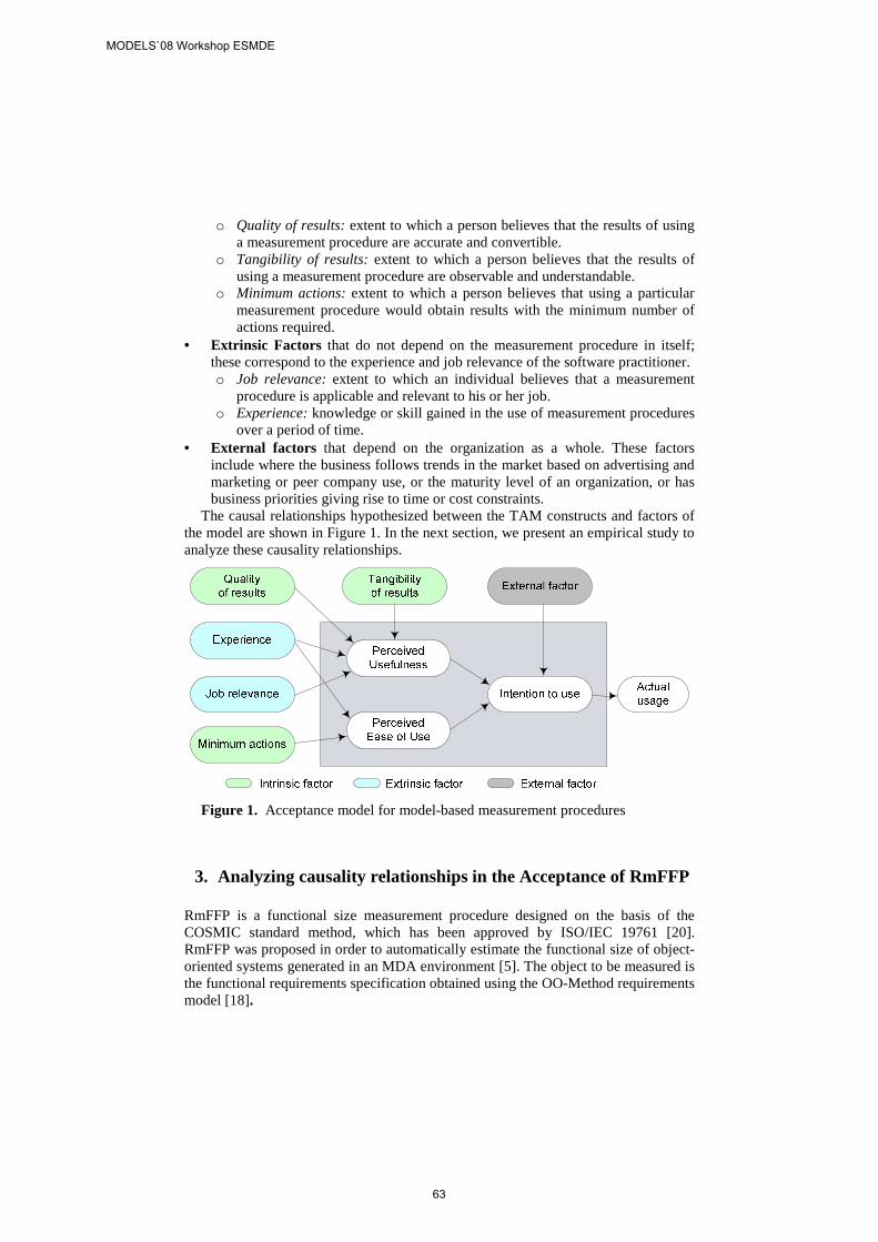
o Quality of results: extent to which a person believes that the results of using a measurement procedure are accurate and convertible.
o Tangibility of results: extent to which a person believes that the results of using a measurement procedure are observable and understandable.
o Minimum actions: extent to which a person believes that using a particular measurement procedure would obtain results with the minimum number of actions required.
• Extrinsic Factors that do not depend on the measurement procedure in itself; these correspond to the experience and job relevance of the software practitioner. o Job relevance: extent to which an individual believes that a measurement
procedure is applicable and relevant to his or her job. o Experience: knowledge or skill gained in the use of measurement procedures
over a period of time. • External factors that depend on the organization as a whole. These factors
include where the business follows trends in the market based on advertising and marketing or peer company use, or the maturity level of an organization, or has business priorities giving rise to time or cost constraints.
The causal relationships hypothesized between the TAM constructs and factors of the model are shown in Figure 1. In the next section, we present an empirical study to analyze these causality relationships.
Figure 1. Acceptance model for model-based measurement procedures
3. Analyzing causality relationships in the Acceptance of RmFFP
RmFFP is a functional size measurement procedure designed on the basis of the COSMIC standard method, which has been approved by ISO/IEC 19761 [20]. RmFFP was proposed in order to automatically estimate the functional size of object-oriented systems generated in an MDA environment [5]. The object to be measured is the functional requirements specification obtained using the OO-Method requirements model [18].
MODELS`08 Workshop ESMDE
63
This procedure starts with the definition of the measurement strategy, which includes the purpose, the scope, and the measurement viewpoint. The scope of RmFFP comprises the functionality to be included in a particular measurement. The measurement viewpoint corresponds to the ‘analyst’ viewpoint, which will focus on a requirements specification (object of interest).
Then, RmFFP starts a mapping phase to identify the significant primitives of the Requirements Model that contribute to the system’s functional size according to the concepts of the COSMIC [20]. We defined sixteen mapping rules whose principal purpose is to reduce misinterpretation about the COSMIC generic concepts and to facilitate the automation of the RmFFP procedure. For instance, each use case is identified as a functional process; each message of the sequence diagram is identified as a data movement type, etc. The main outcome of this phase is the identification of data movements that are fundamental components of COSMIC.
Once the data movements have been correctly identified, we proceed with the measurement phase, whose purpose is to produce a quantitative value that represents the software functional size of a requirements specification. To do this, we apply the measurement function, which consists of assigning a numerical value of 1 Cfsu (Cosmic Functional Size Unit) to each data movement. We defined four rules to add together these quantified data movements. To do this, we used the relationship types between use cases to calculate the size of the functional processes (use case) and the size of the entire system
3.1 Planning: Case study
In order to define the goal of our empirical study, we used the Goal/Question/Metric (GQM) template [15], which is described as follows: To analyze the Acceptance Model proposed for the purpose of evaluating RmFFP with respect to their acceptance in the practice from the viewpoint of the researcher in the context of software engineering professors using a measurement procedure for requirements specifications.
From this goal, the following research questions were addressed by this study: RQ1: is perceived usefulness of the RmFFP measurement procedure really influenced by certain intrinsic factors? RQ2: is perceived usefulness of the RmFFP measurement procedure really influenced by certain extrinsic factors? RQ3: is perceived ease of use the RmFFP measurement procedure really influenced by certain intrinsic factors? RQ4: is the intention to use really a result of the perceptions experienced by the subjects using the RmFFP measurement procedure?
Selection of subjects. The subjects were 20 professors from various Peruvian universities. They were enrolled in the United Nations summer school on “Advanced Techniques in Software Development”, February - March 2007. The careful selection of participants was based on academic qualifications, teaching or industrial experience, technical background, and specific interest in software engineering. The
MODELS`08 Workshop ESMDE
64
empirical study was organized as a part of the “Measurement and Software Quality” course given during the summer school.
Variables and Hypotheses. Using the framework proposed by Juristo and Moreno [16], we identified three types of variables: • Response variables: variables that correspond to the outcomes of the empirical
study. For this study, we considered certain factors and constructs of the Model as response variables: Perceived Ease of Use (PEOU), Perceived Usefulness (PU), Intention to Use (IU), Job Relevance (JR), Quality of Results (QR), Tangibility of Results (TR), and Minimum Actions (MA). We omitted the extrinsic factor: “experience” and the external factors, which will be considered in further studies. As these outcomes should be measurable, we used a 5-point Likert scale format.
• Factors: variables that affect the response variable. In our study, this variable corresponds to the Models-based Measurement Procedures, and as single treatment: the RmFFP procedure [5]
• Parameters: variables that we do not want to influence the experimental results: level of practitioner’s experience using a measurement procedure; complexity of conceptual models to be measured.
The following hypotheses regarding the research questions were considered: H1: Perceived Usefulness is determined by the quality of results of the RmFFP measurement procedure. H2: Perceived Usefulness is determined by the tangibility of results of the RmFFP measurement procedure. H3: Perceived Usefulness is determined by job relevance using the RmFFP measurement procedure for the software practitioner. H4: Perceived ease of use is determined by the minimum number of actions required using the RmFFP measurement procedure. H5: Intention to use is determined by usefulness perceived. H6: Intention to use is determined by perceived ease of use.
3.2 The Collection Data Method
First, we gave an introduction on how to apply the RmFFP measurement procedure by means of illustrative examples. Finally, we verified the knowledge learned by the participants by working through an assigned application. The time used for the training session was 4 hours distributed over two days. Then, each subject used the RmFFP measurement guide to measure a requirements specification of a Car Rental application with thirty-five use cases. The time allowed for this task was unlimited.
Finally, each subject was asked to complete a specially-designed survey to evaluate RmFFP acceptance. The time allowed for this task was also unlimited.
MODELS`08 Workshop ESMDE
65
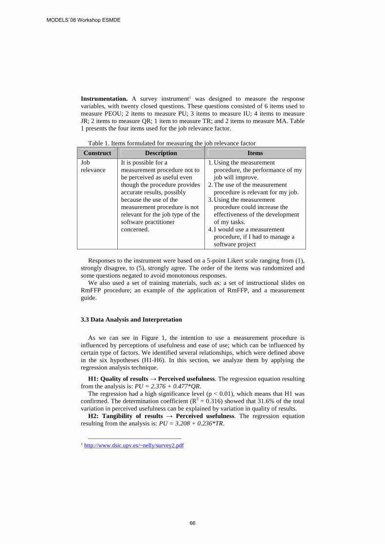
Instrumentation. A survey instrument1 was designed to measure the response variables, with twenty closed questions. These questions consisted of 6 items used to measure PEOU; 2 items to measure PU; 3 items to measure IU; 4 items to measure JR; 2 items to measure QR; 1 item to measure TR; and 2 items to measure MA. Table 1 presents the four items used for the job relevance factor.
Table 1. Items formulated for measuring the job relevance factor
Construct Description Items
Job relevance
It is possible for a measurement procedure not to be perceived as useful even though the procedure provides accurate results, possibly because the use of the measurement procedure is not relevant for the job type of the software practitioner concerned.
1. Using the measurement procedure, the performance of my job will improve.
2. The use of the measurement procedure is relevant for my job.
3. Using the measurement procedure could increase the effectiveness of the development of my tasks.
4. I would use a measurement procedure, if I had to manage a software project
Responses to the instrument were based on a 5-point Likert scale ranging from (1),
strongly disagree, to (5), strongly agree. The order of the items was randomized and some questions negated to avoid monotonous responses.
We also used a set of training materials, such as: a set of instructional slides on RmFFP procedure; an example of the application of RmFFP, and a measurement guide.
3.3 Data Analysis and Interpretation
As we can see in Figure 1, the intention to use a measurement procedure is influenced by perceptions of usefulness and ease of use; which can be influenced by certain type of factors. We identified several relationships, which were defined above in the six hypotheses (H1-H6). In this section, we analyze them by applying the regression analysis technique.
H1: Quality of results → Perceived usefulness. The regression equation resulting from the analysis is: PU = 2.376 + 0.477*QR.
The regression had a high significance level (p < 0.01), which means that H1 was confirmed. The determination coefficient (R2 = 0.316) showed that 31.6% of the total variation in perceived usefulness can be explained by variation in quality of results.
H2: Tangibility of results → Perceived usefulness. The regression equation resulting from the analysis is: PU = 3.208 + 0.236*TR.
1 http://www.dsic.upv.es/~nelly/survey2.pdf
MODELS`08 Workshop ESMDE
66
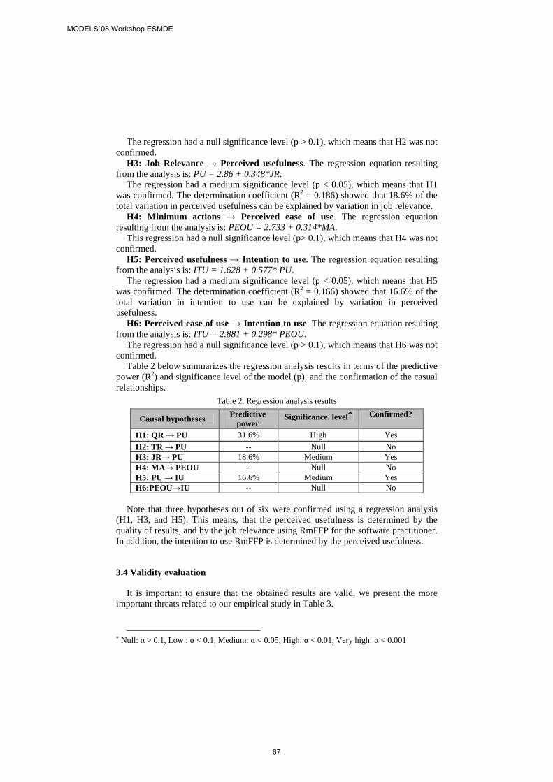
The regression had a null significance level (p > 0.1), which means that H2 was not confirmed.
H3: Job Relevance → Perceived usefulness. The regression equation resulting from the analysis is: PU = 2.86 + 0.348*JR.
The regression had a medium significance level (p < 0.05), which means that H1 was confirmed. The determination coefficient (R2 = 0.186) showed that 18.6% of the total variation in perceived usefulness can be explained by variation in job relevance.
H4: Minimum actions → Perceived ease of use. The regression equation resulting from the analysis is: PEOU = 2.733 + 0.314*MA.
This regression had a null significance level (p> 0.1), which means that H4 was not confirmed.
H5: Perceived usefulness → Intention to use. The regression equation resulting from the analysis is: ITU = 1.628 + 0.577* PU.
The regression had a medium significance level (p < 0.05), which means that H5 was confirmed. The determination coefficient (R2 = 0.166) showed that 16.6% of the total variation in intention to use can be explained by variation in perceived usefulness.
H6: Perceived ease of use → Intention to use. The regression equation resulting from the analysis is: ITU = 2.881 + 0.298* PEOU.
The regression had a null significance level (p > 0.1), which means that H6 was not confirmed.
Table 2 below summarizes the regression analysis results in terms of the predictive power (R2) and significance level of the model (p), and the confirmation of the casual relationships.
Table 2. Regression analysis results
Causal hypotheses Predictive power
Significance. level* Confirmed?
H1: QR → PU 31.6% High Yes
H2: TR → PU -- Null No H3: JR→ PU 18.6% Medium Yes H4: MA→ PEOU -- Null No H5: PU → IU 16.6% Medium Yes H6:PEOU→IU -- Null No
Note that three hypotheses out of six were confirmed using a regression analysis
(H1, H3, and H5). This means, that the perceived usefulness is determined by the quality of results, and by the job relevance using RmFFP for the software practitioner. In addition, the intention to use RmFFP is determined by the perceived usefulness.
3.4 Validity evaluation
It is important to ensure that the obtained results are valid, we present the more important threats related to our empirical study in Table 3.
* Null: α > 0.1, Low : α < 0.1, Medium: α < 0.05, High: α < 0.01, Very high: α < 0.001
MODELS`08 Workshop ESMDE
67
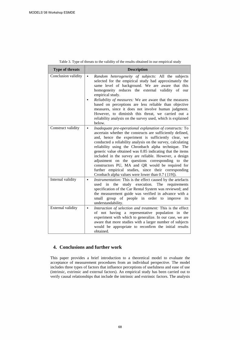
Table 3. Type of threats to the validity of the results obtained in our empirical study
Type of threats Description
Conclusion validity • Random heterogeneity of subjects: All the subjects selected for the empirical study had approximately the same level of background. We are aware that this homogeneity reduces the external validity of our empirical study.
• Reliability of measures: We are aware that the measures based on perceptions are less reliable than objective measures, since it does not involve human judgment. However, to diminish this threat, we carried out a reliability analysis on the survey used, which is explained below.
Construct validity • Inadequate pre-operational explanation of constructs: To ascertain whether the constructs are sufficiently defined, and, hence the experiment is sufficiently clear, we conducted a reliability analysis on the survey, calculating reliability using the Chronbach alpha technique. The generic value obtained was 0.85 indicating that the items included in the survey are reliable. However, a design adjustment on the questions corresponding to the constructors PU, MA and QR would be required for further empirical studies, since their corresponding Cronbach alpha values were lower than 0.7 ( [19]).
Internal validity • Instrumentation: This is the effect caused by the artefacts used in the study execution. The requirements specification of the Car Rental System was reviewed; and the measurement guide was verified in advance with a small group of people in order to improve its understandability.
External validity • Interaction of selection and treatment: This is the effect of not having a representative population in the experiment with which to generalize. In our case, we are aware that more studies with a larger number of subjects would be appropriate to reconfirm the initial results obtained.
4. Conclusions and further work
This paper provides a brief introduction to a theoretical model to evaluate the acceptance of measurement procedures from an individual perspective. The model includes three types of factors that influence perceptions of usefulness and ease of use (intrinsic, extrinsic and external factors). An empirical study has been carried out to verify causal relationships that include the intrinsic and extrinsic factors. The analysis
MODELS`08 Workshop ESMDE
68
shows that perceived usefulness is influenced by the job relevance of the people that use a measurement procedure. However, with respect to intrinsic factors, only the quality of results could affect the perception of usefulness. Perceived ease of use cannot be determined by the minimum actions factor. Furthermore, the results show that the intention to use a measurement procedure can be influenced more strongly by perceived usefulness than by perceived ease of use. We plan to make further adjustments to the questions on the survey to improve the reliability of certain constructs, such as PU, MA, and QR. In addition, we are aware that further experimentation with industry practitioners will be appropriate in order to reconfirm these initial results. Finally, as further empirical studies, we also intend to consider the influence of software practitioners’ experience on the acceptance of model-based measurement procedures.
Referencias
[1] Kasunic M., State of Software Measurement Practice Survey, Carnegie Mellon, Software Engineering Institute, 2006, www.sei.cmu.edu/sema/presentations/stateof-survey.pdf
[2] Abrahão S., Gomez J., Insfran E. Mendes E., A Model-Driven Measurement Procedure for Sizing Web Applications, Conference on Model-Driven Engineering Languages and Systems (MODELS 2007), Nashville, TN, USA, September 30-Octuber 5, 2007, LNCS Springer, 2007.
[3] Abrahao S., Poels G., Pastor O. A Functional Size Measurement Method for Object-Oriented Conceptual Schemas: Design and Evaluation Issues. Software & System Modelling, 5(1): 48-71, Springer Verlag, 2005.
[4] Azzouz S., Abran A., “A Proposed Measurement Role in the Rational Unified Process and its Implementation with ISO 19761: COSMIC-FFP” in Software Measurement European Forum, Rome, Italy, 2004.
[5] Condori-Fernández N., Abrahão S., and Pastor O., On the Estimation of Software Functional Size from Requirements Specifications, Journal of Computer Science and Technology (JCST), Springer, 22(3): 358-370, 2007.
[6] Marín B., Pastor O., Giachetti G.: Automating the Measurement of Functional Size of Conceptual Models in an MDA Environment, 9th International Conference Product-Focused Software Process Improvement, Italy, June 2008, pp. 215-229.
[7] R.B. Cooper and R.W Zmud, “Information Technology Implementation Research: A Technological Diffusion Approach”, Management Science, 36(2):123-139, 1990
[8] W. G. Chismar, S. Wiley-Patton, Does the Extended Technology Acceptance Model Apply to Physicians?, 36th Annual Hawaii International Conference on System Sciences, IEEE Computer Society, Big Island, USA, January 2003, pp. 160-167.
[9] Chau P.Y. K., An empirical investigation on factors affecting the acceptance of CASE by systems developers, Journal on Information and Management, Elsevier, 30(6): 269-280, 1996.
MODELS`08 Workshop ESMDE
69
[10] Umarji M.and Emurian H., Acceptance Issues in Metrics Program Implementation, Proceedings of the 11th IEEE International Software Metrics Symposium METRICS 05, IEEE Computer Society, 2005, Washington,USA, pp. 10-29.
[11] Gopal A., Krishnan M.S., Mukhopadhyay T., Impact of Institutional Forces on Software Metrics Programs, IEEE Trans. on Software Eng, 31(8):679-695, August 2005.
[12] Gopal A., Krishnan M.S., Mukhopadhyay T., and Goldenson, Measurement Programs in Software Development: Determinants of Success, IEEE Transaction on Software Eng., 28(9):863-875, 2002.
[13] Condori-Fernández N., Pastor O., Towards a Theoretical Model for Evaluating the Acceptance of Model-Driven Measurement Procedures, Proceedings of the 20th International Conference on Software Engineering & Knowledge Engineering, SEKE 2008, San Francisco, USA, July 1-3, 2008, pp. 22-25 .
[14] Davis F. D., "Perceived Usefulness, Perceived Ease of Use and User Acceptance of Information Technology", MIS Quarterly, vol. 3, no. 3, 1989.
[15] Basili V. R. and Rombach H. D., The TAME Project: Towards Improvement-Oriented Software Environments, IEEE Transactions on Software Engineering, 14(6):758-773, 1988.
[16] N. Juristo, Moreno A, Basics of Software Engineering Experimentation, Kluwer Academic Publishers, Boston, 2001.
[17] Condori-Fernández N., Pastor O., An Empirical Study on the Likelihood of Adoption in Practice of a Size Measurement Procedure for Requirements Specification, Sixth International Conference on Quality Software (QSIC 2006), October 2006, Beijing, China, pp. 133-140.
[18] Pastor, O., Molina, J. Model-Driven Arquitecture in Practice. Valencia, Springer Berlin Heidelberg, New York, 2007.
[19] Garson D., Scales and standard measures from statnotes, North Carolina State University, Copyright 1998, last updated March 2008. http://www2.chass.ncsu.edu/garson/pa765/standard.htm.
[20] ISO, ISO/IEC 19761 Software Engineering-COSMIC-FFP-A Functional Size Measurement Method, International Organization for Standardization_ISO, Geneva, 2003.
[21] Moody D. L., The method evaluation model: a theoretical model for validating information systems design methods, 11th European Conference on Information Systems, ECIS 2003, Naples, Italy 16-21 June 2003.
MODELS`08 Workshop ESMDE
70
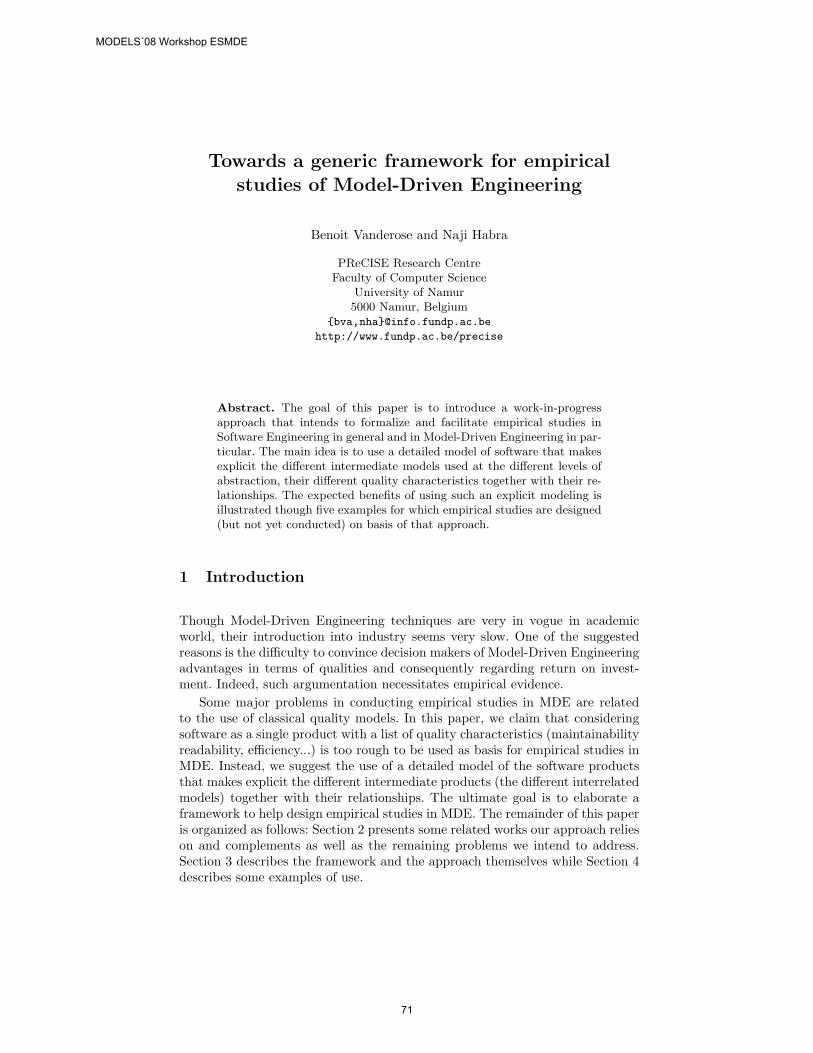
Towards a generic framework for empiricalstudies of Model-Driven Engineering
Benoit Vanderose and Naji Habra
PReCISE Research CentreFaculty of Computer Science
University of Namur5000 Namur, Belgium
{bva,nha}@info.fundp.ac.be
http://www.fundp.ac.be/precise
Abstract. The goal of this paper is to introduce a work-in-progressapproach that intends to formalize and facilitate empirical studies inSoftware Engineering in general and in Model-Driven Engineering in par-ticular. The main idea is to use a detailed model of software that makesexplicit the different intermediate models used at the different levels ofabstraction, their different quality characteristics together with their re-lationships. The expected benefits of using such an explicit modeling isillustrated though five examples for which empirical studies are designed(but not yet conducted) on basis of that approach.
1 Introduction
Though Model-Driven Engineering techniques are very in vogue in academicworld, their introduction into industry seems very slow. One of the suggestedreasons is the difficulty to convince decision makers of Model-Driven Engineeringadvantages in terms of qualities and consequently regarding return on invest-ment. Indeed, such argumentation necessitates empirical evidence.
Some major problems in conducting empirical studies in MDE are relatedto the use of classical quality models. In this paper, we claim that consideringsoftware as a single product with a list of quality characteristics (maintainabilityreadability, efficiency...) is too rough to be used as basis for empirical studies inMDE. Instead, we suggest the use of a detailed model of the software productsthat makes explicit the different intermediate products (the different interrelatedmodels) together with their relationships. The ultimate goal is to elaborate aframework to help design empirical studies in MDE. The remainder of this paperis organized as follows: Section 2 presents some related works our approach relieson and complements as well as the remaining problems we intend to address.Section 3 describes the framework and the approach themselves while Section 4describes some examples of use.
MODELS´08 Workshop ESMDE
71
2 Related work and Issues
The effort described here relies on research linked to both quality measurementand empirical software engineering. The basis of empirical studies in softwareengineering can be found in [28, 18]. Software measurement has witnessed toomany metric proposals to cite them here but also benefits from generic theoreticalworks like [9, 16] while quality assessment benefits from numerous quality mod-els — notably McCall’s [25, 19], Boehm’s [3, 2], FURPS [15], ISO [17], Dromey’s[8]. Unfortunately those works do not take explicitly into account design-relatedquality. Software design quality still benefits from its own research. For instance,[6] summarizes many object-oriented design measures and studies the relation-ships between them and software quality. We can find publications, notably [13,14, 12, 11, 10, 20, 21], that focus on how to estimate the quality of models. Finally,a generic approach to evaluate design is also proposed in [7].
Nevertheless we still identify some difficulties and limitations that appearwhen conducting empirical investigations in Software Engineering in general andin Model-Driven Engineering in particular.
To begin with, software measurement methods in general lack clarity aboutwhat they really measure. Theoretically, measurement process consists in quan-tifying relevant features (attributes) of a product (entity) in order to estimateanother feature (quality) that is not directly quantifiable [9]. Practically, theentity supposed to be measured is very frequently not defined in a precise wayand roughly called “software”. If this view is sufficient for some empirical studiesfocusing on the quality of the software product as a whole, investigating Model-Driven Engineering necessitates more. In fact, since Model-Driven Engineeringcopes with different models and handles them as distinguished products, thequalities of the different models have to be clearly distinguished.
Moreover, the attribute supposed to be measured is frequently unclear. Num-bers produced by applying a measurement method on a given model are some-times used to estimate or predict different attributes without any clarification— e.g., a complexity measurement method used as size measurement. This canlead to incongruous use of software metrics and therefore to a completely wrong,or at least biased, quality assessment [16].
Model-Driven Engineering deals with a succession of models, from the moreabstract ones to the code. Each model corresponds to a given abstraction leveland has its own concerns about quality. But, as any model produced duringsoftware development is a part of an overall workflow, the inner quality of a givenmodel is as important as the preservation of this quality through subsequenttransformation steps leading to the final product. As a consequence, it can beunclear whether a quality criteria of a given model from a given developmentstep actually improves or worsens the quality of the overall software product.
Also, Model-Driven Engineering is based on model transformations. However,research focuses are usually put on the preservation of semantic properties —the correctness of a transformation is defined on that basis. Traditional seman-tics approaches only encapsulate the “functional” aspects while empirical studiesare needed to estimate a larger set of software quality attributes — including
MODELS´08 Workshop ESMDE
72
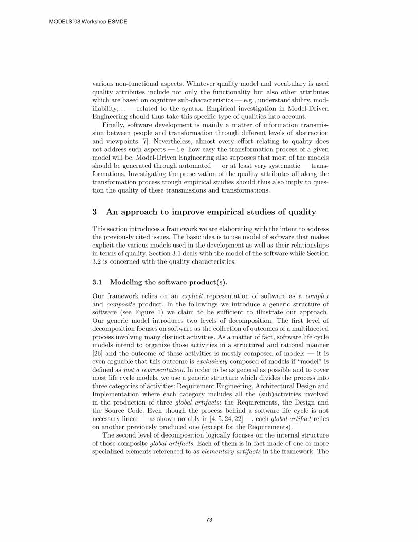
various non-functional aspects. Whatever quality model and vocabulary is usedquality attributes include not only the functionality but also other attributeswhich are based on cognitive sub-characteristics — e.g., understandability, mod-ifiability,. . . — related to the syntax. Empirical investigation in Model-DrivenEngineering should thus take this specific type of qualities into account.
Finally, software development is mainly a matter of information transmis-sion between people and transformation through different levels of abstractionand viewpoints [7]. Nevertheless, almost every effort relating to quality doesnot address such aspects — i.e. how easy the transformation process of a givenmodel will be. Model-Driven Engineering also supposes that most of the modelsshould be generated through automated — or at least very systematic — trans-formations. Investigating the preservation of the quality attributes all along thetransformation process trough empirical studies should thus also imply to ques-tion the quality of these transmissions and transformations.
3 An approach to improve empirical studies of quality
This section introduces a framework we are elaborating with the intent to addressthe previously cited issues. The basic idea is to use model of software that makesexplicit the various models used in the development as well as their relationshipsin terms of quality. Section 3.1 deals with the model of the software while Section3.2 is concerned with the quality characteristics.
3.1 Modeling the software product(s).
Our framework relies on an explicit representation of software as a complexand composite product. In the followings we introduce a generic structure ofsoftware (see Figure 1) we claim to be sufficient to illustrate our approach.Our generic model introduces two levels of decomposition. The first level ofdecomposition focuses on software as the collection of outcomes of a multifacetedprocess involving many distinct activities. As a matter of fact, software life cyclemodels intend to organize those activities in a structured and rational manner[26] and the outcome of these activities is mostly composed of models — it iseven arguable that this outcome is exclusively composed of models if “model” isdefined as just a representation. In order to be as general as possible and to covermost life cycle models, we use a generic structure which divides the process intothree categories of activities: Requirement Engineering, Architectural Design andImplementation where each category includes all the (sub)activities involvedin the production of three global artifacts: the Requirements, the Design andthe Source Code. Even though the process behind a software life cycle is notnecessary linear — as shown notably in [4, 5, 24, 22] —, each global artifact relieson another previously produced one (except for the Requirements).
The second level of decomposition logically focuses on the internal structureof those composite global artifacts. Each of them is in fact made of one or morespecialized elements referenced to as elementary artifacts in the framework. The
MODELS´08 Workshop ESMDE
73
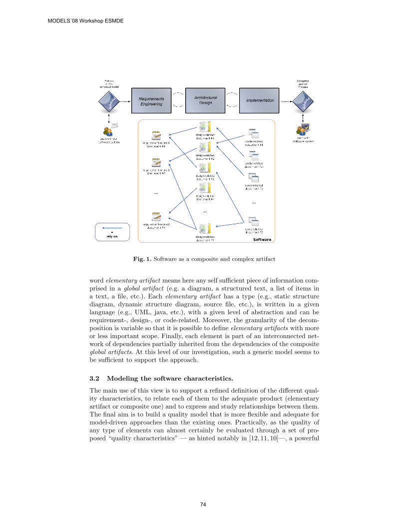
Fig. 1. Software as a composite and complex artifact
word elementary artifact means here any self sufficient piece of information com-prised in a global artifact (e.g. a diagram, a structured text, a list of items ina text, a file, etc.). Each elementary artifact has a type (e.g., static structurediagram, dynamic structure diagram, source file, etc.), is written in a givenlanguage (e.g., UML, java, etc.), with a given level of abstraction and can berequirement-, design-, or code-related. Moreover, the granularity of the decom-position is variable so that it is possible to define elementary artifacts with moreor less important scope. Finally, each element is part of an interconnected net-work of dependencies partially inherited from the dependencies of the compositeglobal artifacts. At this level of our investigation, such a generic model seems tobe sufficient to support the approach.
3.2 Modeling the software characteristics.
The main use of this view is to support a refined definition of the different qual-ity characteristics, to relate each of them to the adequate product (elementaryartifact or composite one) and to express and study relationships between them.The final aim is to build a quality model that is more flexible and adequate formodel-driven approaches than the existing ones. Practically, as the quality ofany type of elements can almost certainly be evaluated through a set of pro-posed “quality characteristics” — as hinted notably in [12, 11, 10]—, a powerful
MODELS´08 Workshop ESMDE
74
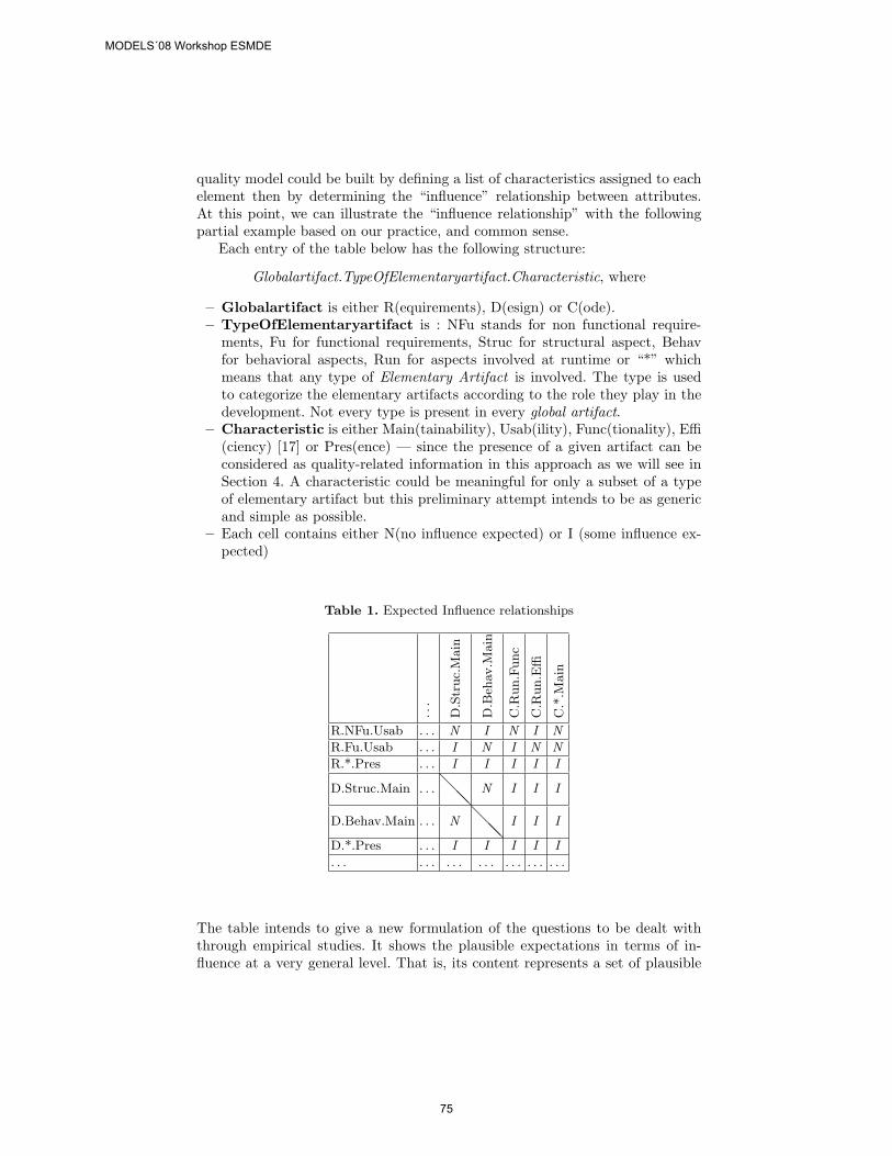
quality model could be built by defining a list of characteristics assigned to eachelement then by determining the “influence” relationship between attributes.At this point, we can illustrate the “influence relationship” with the followingpartial example based on our practice, and common sense.
Each entry of the table below has the following structure:
Globalartifact.TypeOfElementaryartifact.Characteristic, where
– Globalartifact is either R(equirements), D(esign) or C(ode).– TypeOfElementaryartifact is : NFu stands for non functional require-
ments, Fu for functional requirements, Struc for structural aspect, Behavfor behavioral aspects, Run for aspects involved at runtime or “*” whichmeans that any type of Elementary Artifact is involved. The type is usedto categorize the elementary artifacts according to the role they play in thedevelopment. Not every type is present in every global artifact.
– Characteristic is either Main(tainability), Usab(ility), Func(tionality), Effi(ciency) [17] or Pres(ence) — since the presence of a given artifact can beconsidered as quality-related information in this approach as we will see inSection 4. A characteristic could be meaningful for only a subset of a typeof elementary artifact but this preliminary attempt intends to be as genericand simple as possible.
– Each cell contains either N(no influence expected) or I (some influence ex-pected)
Table 1. Expected Influence relationships
...
D.S
truc.
Main
D.B
ehav
.Main
C.R
un.F
unc
C.R
un.E
ffi
C.*
.Main
R.NFu.Usab . . . N I N I N
R.Fu.Usab . . . I N I N N
R.*.Pres . . . I I I I I
D.Struc.Main . . . @@@
N I I I
D.Behav.Main . . . N @@@
I I I
D.*.Pres . . . I I I I I
. . . . . . . . . . . . . . . . . . . . .
The table intends to give a new formulation of the questions to be dealt withthrough empirical studies. It shows the plausible expectations in terms of in-fluence at a very general level. That is, its content represents a set of plausible
MODELS´08 Workshop ESMDE
75
hypotheses to explore through empirical investigations, each of them involvinggoing to a lower level (subtype of element artifact, quality sub-characteristic andinternal metrics). The table is far from being final at this point and each “path”can be questioned. Also, this current table is only focusing on very generic char-acteristics so that each user of the framework can expand, propose and studynew relationships or refine existing ones with different characteristics or otherclassifications of artifacts. So it is only through the massive use of the proposedmethod within the community of Empirical Software Engineering that a con-sensual and widely accepted table of this kind could be achieved. We believethat such table would be a more helpful basis to conduct empirical studies inmodel-driven engineering than usual quality models.
4 Some typical scenarios of use
The novelty of the framework introduced above lies in the particular point ofview adopted. It is more flexible in the sense that it allows to get inside Model-Driven process and investigate the influence of various artifacts on other ones.Then this approach supports more specialized investigation such as the relevanceof a particular transformation in comparison with another.
The first step in order to use the framework is to make explicit the dependen-cies between studied artifacts — e.g., elementary artifact c1 is produced thanksto d1 and d2. Then the idea is to consider these variables as “typed” variableswhere each “type” (requirement-, design, code-related) has its own set of mean-ingful quality characteristics. Finally, the table of influences is used to expressthe hypotheses about the characteristics involved and their relationships. Besidesbeing an innovative way to support empirical studies in general, the present ap-proach particularly suits Model-Driven Engineering for two main reasons. First,most of elementary artifacts, are supposed to be models. Since elementary ar-tifacts are almost the primary form of expression of our framework and modelsare the one of MDE, the two approaches should be compatible. Secondly, ourapproach is designed to address the transformation of information, which is acore concept of any model-driven approach.
The remainder of this Section illustrates the use of the framework on fivehypothetical experiments and highlights the benefits of the framework in thosesituations. The structure of the cases is inspired by the GQM paradigm [1, 27].Case 1
– Goal. Study the impact of the presence of a design pattern P on the main-tainability of the produced code.
– Question. Let d1, d2 be 2 class diagrams, where d2 satisfies the same setof requirement-related elementary artifacts REQ1 than d1, but d1 uses adesign pattern P while d2 does not; c1 & c2 are two pieces of java programproduced from d1, d2, respectively, through a transformation T. Is c2 moremaintainable than c1?
MODELS´08 Workshop ESMDE
76
– Metrics. To study the maintainability of the code, the experimenter coulduse the effort needed to complete a maintenance task as a metric. This is con-sistent with classical quality models which propose to decompose maintain-ability into sub-characteristics which are mainly measurable through effort.Though the choice of such measurement method is questionable by itself, itcould still be used as an approximation.
– Discussion. This experiment could be achieved without the support of theframework but would miss some benefits. With our framework, this exper-iment can be expressed as the investigation of the influence of a structuraldesign-related elementary artifact on the maintainability of a code-relatedelementary artifact. This path is present in the table of expected influences(Table 3.2), which means that the experiment seems relevant. Moreover, theuse of the framework highlights the fact than design patterns are part of thedesign and not the code, a view that is not always admitted.
Case 2
– Goal. Study the impact of one design characteristic on the same character-istic at the code level. For instance the goal could be to investigate whethera focus on the maintainability at the design level does not produce morecomplex code and therefore impact negatively the global maintainability ofthe software product.
– Question. Let d1, d2 be 2 diagrams at the design level, where d1 is moremaintainable than d2, and c1 & c2 be two pieces of java program producedfrom d1 & d2, respectively, through a transformation T. Is c2 more main-tainable than c1?
– Metrics. This situation illustrates perfectly the case where the present ap-proach complements and is nurtured by other related works when it comesto selecting the adequate metrics. Indeed, we can use and integrate to theframework the research that has been done regarding the maintainability ofUML diagrams and how to evaluate it thanks to internal metrics [12, 11].For the code maintainability, see Case 1.
– Discussion. This case is almost similar to the first one but illustrates howthe framework allows us to further investigate software quality. While thefirst case was about the influence of a technique on a quality characteristic,this case proposes to confront the quality characteristics of two entities andsee how they are related. Without the framework and its specific point ofview, this experiment — the investigation of the influence of the maintain-ability of a design-related elementary artifact on the maintainability of acode-related elementary artifact — would need an extra descriptive effort toshow that maintainability does not apply to the same entity on both sidesof the relationship.
Case 3
– Goal. Study the impact of one design characteristic on another characteristicat the code level. For instance the goal could be to investigate whether a
MODELS´08 Workshop ESMDE
77
focus on the maintainability all along the design process does not impactnegatively the efficiency of the software code.
– Question. Let d1, d2 be 2 design models where d1 is more maintainablethan d2 and c1 & c2 be two pieces of java program produced from d1, d2,respectively, through a transformation T. Is c2 more efficient than c1?
– Metrics. The same principles as in Case 2 apply for d1 and d2. Metricsrelated to efficiency could be specifically designed for the experiment ortaken from ISO standards.
– Discussion. This case is set at the same level than Case 2 : the aim is tostudy internal mechanisms of software quality by questioning the relationshipbetween two quality characteristics. The framework helps give sense to thisexperiment : though maintainability and efficiency do not seem to be relatedin any way when applied to the same entity, the framework allows us expressthe fact that a relation of cause and effect exists between the two elementaryartifacts and probably between their respective quality characteristics. Inthis context, the legitimacy of the question is clearer.
Case 4
– Goal. Study the benefits of a given transformation methodology (or tool)regarding the preservation of a given quality characteristic. For instance thegoal could be to question whether a transformation T preserves, improvesor worsens the complexity of the software code.
– Question. Let DES be a collection of design-related elementary artifacts(e.g., class diagrams & statecharts & sequence diagrams) and let C1, C2,. . . ,Cn be different source code — and thus global artifacts — produced bythe transformations T1, T2,. . . ,Tn, respectively. Is C1 more complex thanC2,. . . , Cn?
– Metrics. McCabe’s number could be used to assess complexity accordingthat some precaution is taken [23].
– Discussion. This case illustrates how the framework can support investi-gations about the quality of the engineering process. In previous cases, thetransformation process was fixed and the studied variable was an elementaryartifact. Here, we fix the design-related elementary artifacts and investigatehow various transformations provide various level of quality at the code level.
Case 5
– Goal. Determine the relevant level of abstraction — requirement-, design-or code-related — and the suitable models involved where it would be mean-ingful to take a given characteristic into account — e.g., security.
– Question. Let < R1, D1, C1 >, < R2, D2, C2 > and < R3, D3, C3 >be three software products; the non-functional requirement of security ismodeled by an adequate elementary artifact since the requirement level in< R1, D1, C1 >, since the design level in < R2, D2, C2 > and in the codein < R3, D3, C3 >, which is the most secure product?
– Metrics. Security metrics are not proposed here but could be designedspecially for the experiment.
MODELS´08 Workshop ESMDE
78
– Discussion. This case illustrates how the framework can express questionsabout the “temporal” impact of the introduction of some elementary arti-facts. It also shows how the particular point of view chosen in this approachallows to make a quality characteristic out of a very simple attribute like thepresence of absence of a given artifact.
5 Conclusion and future work
The approach introduced in this paper is a first and currently evolving attemptto address some limitations of software quality assessment. Though relying on avery simple and light mechanism, the main benefit brought by this framework isto force the experimenter to adopt a more accurate and flexible view of software.The examples given in Section 4 are just some of the possible experimentationsthat could benefit from it. In each case, the use of “typed variables” clarifiesthe “dimension” involved and allows to avoid ambiguity about what the experi-menter expects to address. Section 4 also illustrates how basic attributes like thepresence of a given elementary artifact become valuable quality criteria whensoftware is considered from this point of view — i.e., as a composite artifactresulting from a network of interconnected pieces of information.
As an early work, the approach naturally lacks experimental data to con-firm all the benefits we expect. The next step of the development will be toapply the framework to an actual empirical study in the context of a studentdevelopment project. The table of expected influences also need experimentalconfirmation, but should eventually constitute a valuable reference for anyoneinterested in further transversal investigations about the internal mechanisms ofsoftware quality.
References
1. Basili, V.R.: Using Measurement to Build Core Competencies in Software. Seminarsponsored by Data and Analysis Center for Software. (2005)
2. Boehm, B.W., Brown, J. R., Lipow, M.: Quantitative evaluation of software quality.In: International Conference on Software Engineering (1976)
3. Boehm, B.W., Brown, J. R., Kaspar, H., Lipow, M., McLeod, G., and Merritt, M.:Characteristics of Software Quality. North Holland (1978)
4. Boehm, B. W.: Software Engineering Economics. 1st. Prentice Hall PTR. (1981)5. Boehm, B. W.: A Spiral Model of Software Development and Enhancement. Com-
puter 21, 5,pp. 61-72. (1988)6. Briand, L.C., Wust, J., Daly, J.W., Porter, D.V.: Exploring the relationships be-
tween design measures and software quality. In: object-oriented systems, Journal ofSystems and Software, 51, 3, pp. 245-273. (2000)
7. Budgen, D.: Software Design. 2. Addison-Wesley Longman Publishing Co.,Inc.(2003)
8. Dromey, R. G.: A model for software product quality. In: IEEE Transactions onSoftware Engineering, no. 2, pp. 146-163. IEEE Computer Society, Los Alamitos(1995)
MODELS´08 Workshop ESMDE
79

9. Fenton, N. E., Pfleeger, S. L. : Software Metrics: a Rigorous and Practical Approach.2nd. PWS Publishing Co. (1998)
10. Genero, M., Piattini, M., Calero, C.: Empirical Validation of Class Diagram Met-rics. In Proceedings of the 2002 international Symposium on Empirical Software En-gineering (October 03 - 04, 2002). International Symposium on Empirical SoftwareEngineering. IEEE Computer Society, Washington, DC (2002)
11. Genero, M., Piattini, M., Manso, E., Cantone, G.: Building UML Class DiagramMaintainability Prediction Models Based on Early Metrics. In: Proceedings of the 9thinternational Symposium on Software Metrics (September 03-05, 2003),METRICS.IEEE Computer Society, Washington, DC (2003)
12. Genero Bocco, M., Moody, D. L., Piattini, M. : Assessing the capability of internalmetrics as early indicators of maintenance effort through experimentation :ResearchArticles. J. Softw. Maint. Evol. 17, 3, pp.225-246 (2005)
13. Genero, M., Piattini, M., Calero, C.: A Survey of Metrics for UML Class DiagramsJournal of Object Technology, 4, 9, 59-92. (2005)
14. Genero, M.: Metrics for Software Conceptual Models. World Scientific PublishingCo., Inc. (2005)
15. Grady, R. B.: Practical Software Metrics for Project Management and ProcessImprovement. Prentice-Hall, Inc, Upper Saddle River, NJ, USA (1992). PracticalSoftware Metrics for Project Management and Process Improvement. Prentice Hall,p. 32.
16. Habra, N., Abran, A., Lopez, M., and Sellami, A.: A framework for the designand verification of software measurement methods. J. Syst. Softw. 81, 5, pp633-648.(2008)
17. ISO/IEC 9126. Software Product Evaluation–Quality Characteristics and Guide-lines for the User, Geneva, International Organization for Standardization. (2001)
18. Juristo, N., Moreno, A.M.: Basics of Software Engineering Experimentation.Kluwer Academic Publishers. (2001)
19. Kitchenham, B., Pfleeger, S. L.: Software quality: the elusive target [special issuessection]. IEEE Software, no. 1, pp. 12-21 (1996)
20. Lange, C.F.J.: Empirical Investigations in Software Architecture Completeness.TU Eindhoven; November 12. (2003)
21. Lange, C., Chaudron, M., Muskens, J.: In Practice: UML Software Architectureand Design Description. In: IEEE Software ,vol. 23, no. 2, pp. 40-46. (2006)
22. Larman, C. and Basili, V. R.: Iterative and Incremental Development: A BriefHistory. Computer 36, 6,pp. 47-56. (2003)
23. Lopez, M., Habra, N., Abran, A.: A Structured Analysis of the McCabe CyclomaticComplexity Measure. In: Proceedings of the 14th International Workshop on SoftwareMeasurement (IWSM2004) Berlin, Germany (2004)
24. Martin, J.: Rapid Application Development. Macmillan Publishing Co., Inc.(1991)25. McCall, J. A., Richards, P. K., Walters, G. F.: Factors in Software Quality. Nat’l
Tech.Information Service, Vol. 1, 2 and 3 (1977)26. Pressman, R. S.: Software Engineering: a Practitioner’s Approach. McGraw-Hill
Science/Engineering/Math.(2004)27. Van Solingen, R.: The Goal/Question/Metric Method. McGraw-Hill Education.
(1999)28. Wohlin, C., Runeson, P., Hst, M., Ohlsson, M.C., Regnell, B., Wessln, A.: Ex-
perimentation in software engineering: an introduction. Kluwer Academic Publishers(2000)
MODELS´08 Workshop ESMDE
80


![E cien t W eb Service Disco v ery and Comp osition using ...ftp.informatik.rwth-aachen.de/Publications/CEUR-WS/Vol-196/alpsws… · [8]. In this con text, a W eb service can b e regarded](https://img.pdfslide.us/doc/110x75/5edb2acb4b926708e224dfd2/e-cien-t-w-eb-service-disco-v-ery-and-comp-osition-using-ftp-8-in-this-con.jpg)


![moves.rwth-aachen.de · Reducing ∞-SafetytoT-Safety SynthesizingStochasticBCs ExperimentalResults ConcludingRemarks. ApplicationsofStochasticDifferentialDynamics ©[PNGGuru] Windforces](https://img.pdfslide.us/doc/110x75/5f7b56f1d1e17c7268721be5/movesrwth-reducing-a-safetytot-safety-synthesizingstochasticbcs-experimentalresults.jpg)