Embed Size (px)
Citation preview

Stable Temp® Model 282A Vacuum Oven
105714 • Rev. 2

Cole-Parmer
MANUAL NUMBER 105714 (7006281)
2 26741/SI-10360 11/9/10 Updated TCCB to comply with in-house test procedure QT049 (pg 6-13) ccs
1 26565/SI-10360 11/1/10 Repl readout thermocouple w/ 255036 ccs
0 -- 3/31/10 Transfer to Marietta (was 105714 2/6/09) ccs
REV ECR/ECN DATE DESCRIPTION By
Preface
Vacuum Oven i
Models covered in this manual
Catalog number Model number Voltage
05017-10 6281 115V
05017-15 6282 230V

Cole-Parmerii Vacuum Oven
Preface
Important Read this instruction manual. Failure to read, understand and follow the instructions in this manualmay result in damage to the unit, injury to operating personnel, and poor equipment performance. s
Caution All internal adjustments and maintenance must be performed by qualified service personnel. s
Material in this manual is for information purposes only. The contents and the product it describes are subject tochange without notice. Cole-Parmer makes no representations or warranties with respect to this manual. In noevent shall Cole-Parmer be held liable for any damages, direct or incidental, arising out of or related to the use ofthis manual.
©2010 Cole-Parmer. All rights reserved.

Cole-Parmer Vacuum Oven iii
Preface
Important operating and/or maintenance instructions. Read the accompanying text carefully.
Potential electrical hazards. Only qualified persons should perform procedures associated with thissymbol.
Equipment being maintained or serviced must be turned off and locked off to prevent possible injury.
Hot surface(s) present which may cause burns to unprotected skin, or to materials which may bedamaged by elevated temperatures.
Marking of electrical and electronic equipment, which applies to electrical and electronic equipmentfalling under the Directive 2002/96/EC (WEEE) and the equipment that has been put on the marketafter 13 August 2005.
This product is required to comply with the European Union’s Waste Electrical & ElectronicEquipment (WEEE) Directive 2002/96/EC. It is marked with the WEEE symbol. Cole-Parmer hascontracted with one or more recycling/disposal companies in each EU Member State EuropeanCountry, and this product should be disposed of or recycled through them. Further information onCole-Parmer’s compliance with this directive, the recyclers in your country and information on Cole-Parmer products will be available at www.coleparmer.com.
4 Always use the proper protective equipment (clothing, gloves, goggles, etc.)
4 Always dissipate extreme cold or heat and wear protective clothing.
4 Always follow good hygiene practices.
4 Each individual is responsible for his or her own safety.

Cole-Parmeriv Vacuum Oven
Preface
Do You Need Information or Assistance
on Cole-Parmer Equipment?
The Cole-Parmer Instruments Sales Group can provide information on pricing and give you
quotations. We can take your order and provide delivery information on major equipment items or
make arrangements to have your local sales representative contact you.
1-800-323-4340 Cole-Parmer, Toll Free, US
Cole-Parmer Instruments Product Service Support can supply technical information about
proper setup, operation or troubleshooting of your equipment. We can fill your needs for
replacement parts or provide you with on-site service. We can also provide you with a quotation on
our Extended Maintenance Program for our products.
Whatever products you need or use, we will be happy to discuss your applications. If you are
experiencing technical problems, working together, we will help you locate the problem and, chances
are, correct it yourself...over the telephone without a service call.
When more extensive service is necessary, we will assist you with direct factory trained
technicians or a qualified service organization for on-the-spot repair. If your service need is covered
by the Cole-Parmer Instruments Products warranty, we will arrange for the unit to be repaired at our
expense and to your satisfaction.
Regardless of your needs, professional service technicians are available by telephone to assist
you concerning our products Monday through Friday from 8:00 a.m. to 6:00 p.m. Eastern Time.
Please call or fax us at:
1-800-323-4340 Toll Free U.S. and Canada
1-847-549-7600 Direct
1-847-549-7676 Fax
International customers, please contact your local Cole-Parmer Instruments distributor.

Vacuum Oven vCole-Parmer
Table of Contents
Introduction . . . . . . . . . . . . . . . . . . . . . . . . . . . . . . . . . . . . . . . . . . . . . . . . .1-1
Performance and Physical Data . . . . . . . . . . . . . . . . . . . . . . . . . . . . . . . .2-1
Unpacking . . . . . . . . . . . . . . . . . . . . . . . . . . . . . . . . . . . . . . . . . . . . . . . . . . .3-1
Control, Indicators and Connectors . . . . . . . . . . . . . . . . . . . . . . . . . . . . .4-1Self-Diagnostic Safety Monitors . . . . . . . . . . . . . . . . . . . . . . . . . . . . .4-4
Installation and Assembly . . . . . . . . . . . . . . . . . . . . . . . . . . . . . . . . . . . . .5-1Site Requirements . . . . . . . . . . . . . . . . . . . . . . . . . . . . . . . . . . . . . . .5-1Installation . . . . . . . . . . . . . . . . . . . . . . . . . . . . . . . . . . . . . . . . . . . . .5-2
Operation . . . . . . . . . . . . . . . . . . . . . . . . . . . . . . . . . . . . . . . . . . . . . . . . . . . .6-1Main Controller Menus . . . . . . . . . . . . . . . . . . . . . . . . . . . . . . . . . . .6-2Establishing Operating Conditions . . . . . . . . . . . . . . . . . . . . . . . . . .6-3Auxiliary Pump Contacts . . . . . . . . . . . . . . . . . . . . . . . . . . . . . . . . . .6-4Setting the Temperature . . . . . . . . . . . . . . . . . . . . . . . . . . . . . . . . . . .6-5
Operation in a Static Environment . . . . . . . . . . . . . . . . . . . . . . . . .6-6Operation in a Controlled Environment . . . . . . . . . . . . . . . . . . . . .6-6Operation in a Vacuum Environment . . . . . . . . . . . . . . . . . . . . . . .6-6Setting the Time and Day . . . . . . . . . . . . . . . . . . . . . . . . . . . . . . . .6-7Temperature/Pressure Offsets . . . . . . . . . . . . . . . . . . . . . . . . . . . . .6-7Programming the Oven . . . . . . . . . . . . . . . . . . . . . . . . . . . . . . . . . .6-8Program Execution - Enabling/Disabling . . . . . . . . . . . . . . . . . . . .6-9
Calibration Procedure . . . . . . . . . . . . . . . . . . . . . . . . . . . . . . . . . . .6-10Calibration Mode . . . . . . . . . . . . . . . . . . . . . . . . . . . . . . . . . . . . .6-11
Maintenance . . . . . . . . . . . . . . . . . . . . . . . . . . . . . . . . . . . . . . . . . . . . . . . .7-1Seal Replacement . . . . . . . . . . . . . . . . . . . . . . . . . . . . . . . . . . . . . . . .7-1Door Alignment Procedure . . . . . . . . . . . . . . . . . . . . . . . . . . . . . . . .7-2
Service . . . . . . . . . . . . . . . . . . . . . . . . . . . . . . . . . . . . . . . . . . . . . . . . . . . . . .8-1Replacement Parts . . . . . . . . . . . . . . . . . . . . . . . . . . . . . . . . . . . . . . .8-3
Electrical Schematic . . . . . . . . . . . . . . . . . . . . . . . . . . . . . . . . . . . . . . . . .9-1
Section 1
Section 2
Section 3
Section 4
Section 5
Section 6
Section 8
Section 7
Section 9


Vacuum Oven 1-1Cole-Parmer
Section 1 Introduction
Before operation, always observe the following safety precautions:
• This unit is not explosion proof.
• Do not use in the presence of flammable or combustible materials; fireor explosion may result. Unit contains components that may ignitesuch materials.
• Do not place volatile items in the chamber.
• Fumes and spillage from acidic solutions cause corrosion of thestainless steel chamber.
• Care should be taken to maintain neutral pH at all times.


Vacuum Oven 2-1Cole-Parmer
Section 2 Performance and PhysicalData
TemperatureTemperature Range . . . . Ambient to 280°C, continuously adjustablewith 1°C resolution
Heat Rise Time . .Ambient to 100°C in <30 minutes, . . . . . . . . . . . . . . . . . . . .with temp set to 200°C
Average Set-Point Accuracy . . . . . . . . . . . . . . . .±2°CCool-Down Time . . . . . .280 to 100°C in ~2.5 hoursTemperature Set-Point Reproducibility . . . . . .±0.1°CTemperature Control Band . . . . . . . . . . . . . . .±0.2°CLong-Term (12 hours) Temp. Stability . . . . .±0.03°CTemperature Display . . . . . 3 digit LED display to nearest to nearest 1°CAverage Temperature Uniformity . . . . ±5°C (in vacuum), based upon
measuring points at the geometric center and each corner of oven cham-ber at 100°C
VacuumAverage Leak Rate . . . . . . . . . .< 1” Hg per 24 hoursVacuum Display Accuracy . . . Average error 0.2 inch Hg between ambient
and complete vacuumAtmosphere Control . . . . Use with non-corrosive, non-flammable gases
such as nitrogen and CO2
EnvironmentalOperating Temperature . . . . . . . . . . . . .60° to 100°FStorage Temperature . . . . . . . . . . . . . . .32° to 120°FHumidity . . . . . . 20 to 80% relative humidity, non-condensing
Recorder OutputsTemperature, Pins P3-1, P3-2 . . . . . . . . .10 mv / °CChamber Pressure, Pins P3-3, P3-4 . .100 mv / in HgConnector Type: . . . . . . . . . . . . . . . .AMP 640456-4

2-2 Vacuum Oven Cole-Parmer
Section 2Performance and Physical Data
Physical CharacteristicsExternal Dimensions . . . . . . . .26”W x 23”D x 22”HChamber Size . . . . . . . . . . . . .12”W x 18”D x 12”HChamber Volume . . . . . . . . . . . . . . . . . . . . .1.5 cu ft

Vacuum Oven 3-1Cole-Parmer
Section 3 Unpacking
Refer to the packing list below and be certain that all listed items arepresent. If any are missing, notify Cole-Parmer. Also, be certain tocomplete and return the included warranty card.
Note If any shipping damage has occurred, retain the unit intact, includingall packing materials, and file claim with the final carrier promptly.Usually, the firm will send an investigator to ascertain liability. s
Unpacking Checklist
Qty Description
1 Oven
2 Shelves (shipped in chamber)
2 Hose Connectors
1 Instruction Manual
1 Warranty Card


Vacuum Oven 4-1Cole-Parmer
Section 4 Control, Indicators andConnectors
Before putting the Oven into operation, the user should becomethoroughly familiar with the location and function of all controls,indicators, and connectors. Most are clearly labeled and located on orbelow the front panel, with the exception of the two (PURGE andVACUUM) hose connectors, which are located on the lower right side ofthe oven. A set of vacuum pump auxiliary contacts and thetemperature/vacuum recorder output connectors are located on the rearside of the control board. See Auxiliary Pump Contacts for instructions onaccessing these connectors.
The control panel consists of two 14-segment alphanumeric displays, sixindicator LEDs, four keypads, and an ON/OFF toggle. The VACUUMand PURGE valves are located just beneath the control panel. The listbelow gives a more detailed explanation of each.
Day/Time DisplayA four character alphanumeric readout that alternately displays the dayof the week and time of day in 5-second intervals.
Temp/Vacuum DisplayA four character alphanumeric readout that alternately displays the tem-perature (°C) and chamber pressure (in Hg) in 5-second intervals.

4-2 Vacuum Oven Cole-Parmer
Section 4Controls, Indicators and Connectors
LED IndicatorsAM: Indicates first 12-hour time is being displayed/programmed in the
upper display window. Flashes when in Calibration mode.
°C: Indicates chamber temperature (°C) is beingdisplayed/programmed in the lower display window.
in Hg: Indicates chamber absolute pressure is being displayed in thelower display window. Also illuminated during vacuum pumpprogram step.
Heater: Indicates heater activation.
Pump: Indicates closed vacuum pump contact condition.
Program: Indicates 7-day program setup or operation.
KeypadsMenu: Allows operator to cycle through main menu and calibration
menu.
Set: Selects one of six main menu parameters and one of fivecalibration menu parameters.
Increase: Increments values to be selected for each parameter.
Decrease: Decrements values to be selected for each parameter.
Connectors and ValvesPower Switch: A rocker type switch that controls all power to the
Vacuum Oven.
Vacuum Control Valve: A forged body, shut-off valve used to open andclose the connection to an auxiliary vacuum pump. Valve portaccepts a supplied serrated fitting to ease in connecting a 1/4-inch(Inside diameter) hose.
Purge Control Valve: A forged body, shut-off valve used to open and closethe connection to an auxiliary gas source. Valve port accepts a suppliedserrated fitting for ease in connecting a 1/4-inch (inside diameter) hose.

Vacuum Oven 4-3Cole-Parmer
Section 4Controls, Indicators, and Connectors
Vacuum Inlet Port: A serrated hose fitting used to connect an auxiliaryvacuum pump to the oven. Fitting accepts a 1/4-inch (inside diameter)hose.
Purge Inlet Port: A serrated hose fitting used to connect an auxiliary gassource to the vacuum oven. Fitting accepts a 1/4-inch (inside diameter)hose.
Vacuum Pump Auxiliary Contacts: Normally open contacts located at thebottom of the rear side of the control board (Tabs 3 & 4). The contactsclose when either the pump is manually activated at the keypad, or byrunning a program step that calls for pump activation.
Temperature and Vacuum Recorder Outputs: Four pins located on thetop, right of the rear side of the control board (P3) which provide a volt-age readout corresponding to chamber temperature and/or pressure.
Calibration Jumper Pin (JP4): Group of four pins located in the center ofthe rear of the control board. The lower two pins when jumped enablecalibration mode. See illustration below for control board rear view.
Battery module
Calibration Jumper P4(shown in Calibration mode)
Recorderoutputs - P3

A group of five messages alert the operator to heater and controlmalfunctions. The OTC (open thermocouple) and OVR (overtemperature) errors alternately display in the TEMP/VACUUM display.The PWRF (power failure), BATT LOW (low battery) and CRC(calibration data corruption) are displayed in the DAY/TIME displaywindow. All messages and their meanings are as follows:
OTC (Open Thermocouple): The TEMP/VACUUM display alternatesbetween OTC and current chamber pressure at 5 second intervals, whereOTC replaces the normal process temperature display field. The heatersand vacuum pump (if connected to auxiliary contacts) are forced OFF.Program execution is halted.
OVR (Over Temperature): Activates if oven temperature exceeds the set-point +20°C.
PWRF (Power Failure): Power failure only detected during program mode.The failure must be longer than 2 minutes. Time display alternatesbetween PWRF, HH:MM and DAY(n) at 5 second intervals.
BATT LOW (Low Battery): Indicates it is time to replace the 6-year bat-tery module. Module is in a socket on the back of the control board. Seecontrol board illustration on previous page.
CRC (Calibration Data Corrupted): Indicates an error in the stored cali-bration data. The heater and pump relay are forced off. Unit must be cal-ibrated to clear.
4-4 Vacuum Oven Cole-Parmer
Section 4Controls, Indicators and Connectors
Self-DiagnosticSafety Monitors

Vacuum Oven 5-1Cole-Parmer
Section 5 Installation and Assembly
The oven is shipped assembled and ready for operation. However, beforeinstalling the oven, the operating site should be prepared to meet necessaryrequirements. Additionally, a few assembly procedures must be performedbefore the oven can be safely and properly operated.
The standard plug configurations are shown in the illustration below. The115VAC model is supplied with a 20 amp plug (NEMA 5-20P). The230VAC model is supplied with a 15 amp plug (NEMA 6-15P). Verifythat the appropriate receptacle is at the location the oven will be used.
Warning To avoid the risk of electrical shock, verify that the source plug isproperly grounded. s
The supporting bench or table must be capable of holding in excess of 200pounds. The bench should be sufficient to accommodate sample-handlingprocesses. The oven itself is 26-inches wide and 23-inches deep; therefore,the bench surface should be approximately 48-inches wide and 30-inchesdeep to allow for ventilation clearance at the rear of the oven.
Warning To avoid the risk of fire, provide 6 inches of clearance for the top,back and sides of the oven. Do not set or lean any objects against or on topof the oven while hot. s
For installations that may use a tank atmosphere, check that site facilitiesand tank equipment are in compliance with OSHA requirements forhandling compressed gas. Responsible personnel must also be thoroughlyknowledgeable in the use, storage, and handling of compressed gases.
Site Requirements
5-20P 6-15P

5-2 Vacuum Oven Cole-Parmer
Section 5Installation and Assembly
When using a tank atmosphere, a 1/4” tube to 1/4” pipe adapter isrequired for the regulator outlet of the tank. This adapter is not supplied.A Swagelok B-400-7-4 adapter, or equivalent, may be used. Also, 9/16”,and 1-1/8” open-end or, preferably, flare-nut wrenches are required.
After verifying all site and safety requirements, the following steps shouldbe completed to prepare the vacuum oven for operation:
1. Verify that all-packing items and securing materials have been removedfrom the oven.
2. Move the oven to the desired location as specified above.
3. Locate the two serrated hose fittings, packed in the INSTRUCTIONSenvelope accompanying each oven.
4. Install the hose fittings on the VACUUM and PURGE ports locatedon the lower right-side panel. Hose fittings should be installed byturning the fitting nut clockwise until finger-tight then, using a 9/16”wrench, turn the nut an additional 1/4-turn while holding the fittingstationary with a 3/8” wrench.
5. Close both the PURGE and VACUUM valves by turning the controlknob clockwise as far as possible.
6. Connect a vacuum pumping system, including a suitable trap, to theserrated fitting labeled VACUUM. Use 1/4-inch I.D. heavy-walledvacuum tubing and secure the connection with a hose clamp.
7. If desired, connect a purge gas supply to the serrated fitting labeledPURGE using a suitable length of 1/4” I.D. tubing. Use a two-stagegas flow regulator if gas is to be supplied by a pressurized cylinder.
8. After installing connecting tubing, check that the PURGE CONTROLvalve on the Oven is closed (full clockwise position) then open theregulator flow control valve to pressurize the line. At this point, checkall connections for leaks using an ordinary soapy water solution.
9. Check data plate and plug line cord into a suitable power receptacle.
Site Requirements(continued)
Installation

Section 6 Operation
Energize the oven by switching the ON/OFF toggle to the ON position.The upper display will show VER while the lower display will show 1.0,indicating the current software version. Next, the DAY/TIME display willbegin alternating between the day of week and the time of day. At thesame time, the TEMP/VACUUM display will alternate between chambertemperature (°C) and chamber pressure (in Hg). Press the MENU key toscroll through menus 1-6, then press SET to enter a menu. If there is nokeypad activity for 5 seconds, the unit returns to Menu 1 automatically.The following table lists the main menus and their functions. The tablesthat follow list the subcategories of the controller main menu and describethe function of each.
Vacuum Oven 6-1Cole-Parmer
Table 2: Default Menu (Menu 1)
Step Key Entry Action Display
1 Press SETUnit enters Temperature Setpoint mode with the currentsetpoint displayed. Use the UP/DOWN keys to adjust thesetpoint.
SP: 280
2 Press SET 2nd Time The temperature setpoint is updated and the vacuum pumpON/OFF option is displayed. Use the UP key to switch thepump on, and the DOWN key to switch the pump off.
PUMP OFF
3 Press SET or wait 2 seconds Unit returns to the default menu. MON 280
Table 1: Main Menu
Menu Prompt Display Functions Setup Functions
1 (Default) Top Display – Day of week, Time of day Adjust temperature control setpoint
Bottom Display – Temp (°C), Pressure (in Hg) Turn vacuum pump contacts ON/OFF
2 ADJT Display temperature offset value Adjust temperature control offset
3 ADJP Displays pressure offset value Adjust for barometric pressure variations
4 TSET Displays flashing day or time value Set clock and day of the week
5 PRGM Displays program mode Start / Stop program mode
6 PSET Displays day, step and setpoint Program 7 – Day event timer

6-2 Vacuum Oven Cole-Parmer
Section 6Operation
Main ControllerMenus
Table 3: Adjust Temperature Offset (Menu 2)
Step Key Entry Action Display
1 Press MENU until ADJT isdisplayed, then press SET
Use the UP/DOWN keys to adjust thetemperature offset. (Range ±30 °C) ADJT 00
2 Press SET or wait 2 seconds Unit returns to the default menu. MON 280
Table 6: Program Mode ON/OFF (Menu 5)
Step Key Entry Action Display
1 Press MENU until PRGM isdisplayed, then press SET
Use the UP/DOWN keys to switch theprogram on or off. PRGM OFF
2 Press SET or wait 2 seconds Unit returns to the default menu. MON 280
Table 4: Adjust Barometric Pressure Offset (Menu 3)
Step Key Entry Action Display
1 Press MENU until ADJT isdisplayed, then press SET
Use the UP/DOWN keys to adjust thepressure offset. (Range ±8.0 in Hg) ADJP 0.0
2 Press SET or wait 2 seconds Unit returns to the default menu. MON 280
Table 5: Set Time and Day (Menu 4)
Step Key Entry Action Display
1 Press MENU until TSET isdisplayed, then press SET
Unit enters set time and day mode andthe current hour and minute is displayed.Hours digits are flashing. Use theUP/DOWN keys to adjust the hour.
08:00 AM •
2 Press SET Minutes digits are flashing. Use theUP/DOWN keys to adjust minutes. 08:00 AM •
3 Press SETDay of the week is displayed (flashing).Use the UP/DOWN keys to adjust the dayof the week.
MON
4 Wait 2 seconds Unit returns to default menu. MON 280

Vacuum Oven 6-3Cole-Parmer
Section 6Operation
EstablishingOperating Conditions
Table 7: Program Edit Mode (Menu 6)
Step Key Entry Action Display
1 Press MENU until PSET is dis-played, then press SET
Unit enters the program editmode and points to MONday,step 1. Use the UP/DOWN keysto select the day and step.
MON1
2 Press UP or DOWN,
Unit displays the program timethen press SET. for the currentstep. Hour digits are flashing. Usethe UP/DOWN keys to adjust hour.
08:00 AM •
3 Press SET Minutes digits are flashing. Usethe UP/DOWN keys to adjustminutes.
08:00AM •
4 Press SET
Step time and temperature set-point is displayed. Setpoint isflashing. Use the UP/DOWN keysto adjust setpoint.
08:00 280
5 Press SET
Program step time & pump statusis displayed. Pump ON or OFF isflashing. Use the UP/ DOWN keysto switch pump ON or OFF.
08:00 OFF
6 Press SET
Unit displays the program day,step and ʻN ?ʼ prompt. Use theUP/DOWN keys to adjust promptto Y to accept or N not accept.
08:00 N ?
7 Press SET, then MENU to exitor SET again to continue
Unit displays the next programstep. To exit the edit session pressMENU, or press SET to view oredit another step.
MON2
8 Press MENU to exit
Unit displays COPY/NO. Thisoption will copy 8 steps forwardto each day through the end ofthe week. Use the UP/DOWNkeys to adjust prompt to Y or N.
NO
Establishing the operating conditions consists of setting the desiredtemperature program and establishing the desired environmentalconditions, e.g., vacuum, inert gas atmosphere, or both. Instructionspertaining to connecting a vacuum pump and/or gas supply to the ovenare given under the INSTALLATION AND ASSEMBLY section of thismanual. Before establishing conditions, be certain that all steps givenunder the aforementioned section have been completed.
Main ControllerMenus (continued)
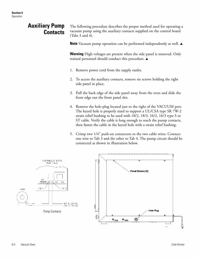
The following procedure describes the proper method used for operating avacuum pump using the auxiliary contacts supplied on the control board(Tabs 3 and 4).
Note Vacuum pump operation can be performed independently as well. s
Warning High voltages are present when the side panel is removed. Onlytrained personnel should conduct this procedure. s
1. Remove power cord from the supply outlet.
2. To access the auxiliary contacts, remove six screws holding the rightside panel in place.
3. Pull the back edge of the side panel away from the oven and slide thefront edge out the front panel slot.
4. Remove the hole-plug located just to the right of the VACUUM port.The keyed hole is properly sized to support a UL/CSA type SR 7W-2strain relief bushing to be used with 18/2, 18/3, 16/2, 16/3 type S orST cable. Verify the cable is long enough to reach the pump contacts,then fasten the cable in the keyed hole with a strain relief bushing.
5. Crimp two 1/4” push-on connectors to the two cable wires. Connectone wire to Tab 3 and the other to Tab 4. The pump circuit should beconnected as shown in illustration below.
6-4 Vacuum Oven Cole-Parmer
Section 6Operation
Auxiliary PumpContacts
Pump Contacts
6. Reattach the side panel using the six side panel screws.
7. Connect the vacuum hose to the Vacuum Inlet Port on the side of theoven and open the Vacuum valve. Close the door and the Purge InletPort by turning Purge valve clockwise completely.
8. Plug the oven in and switch the ON/OFF toggle to the ON position.The top and bottom displays will alternately flash between time ofday/day of the week and chamber temperature/pressure, respectively.
Caution The maximum allowable current in auxiliary circuit is 6 amps. SeePerformance Characteristics for contact ratings before applying power. s
9. Press the SET key until PUMP is displayed in the upper displaywindow. Press the UP arrow key. The lower display window shouldshow ON. Press the SET key again or leave as is for two seconds. Thecontacts will close and the pump should turn on. Control will thenrevert to the default mode after five seconds.
10. While the pump evacuates the chamber, the chamber pressure shouldbegin to drop as indicated by the lower display. The bottom displayalternately shows chamber pressure (in Hg) and chamber temperature(°C).
11. To turn off the pump, press the SET key until PUMP is displayed inthe upper display window. Press the DOWN ARROW key. OFFshould then be displayed in the lower display window. Press SET orleave as is for two seconds. The auxiliary pump contacts will open andthe pump should turn off.
As noted above, the vacuum pump can be controlled as described ormanually using an external switch.
To set the oven temperature, begin by pressing the SET key. The upperdisplay will show SP while the lower display indicates the last settemperature or OFF, indicating the heaters are turned off. Next use theUP/DOWN arrow keys to toggle through temperature values. When thedesired temperature is displayed, press the SET key to enter the value.Return to the default mode by continuously pressing MENU or leave as isfor two seconds and control will revert to the default mode automatically.
Note If fast warm up is desired, the temperature must be set atapproximately 25°C higher than the final temperature, then set back to thefinal temperature when the oven reaches a temperature within 10°C of thefinal temperature. s
Vacuum Oven 6-5Cole-Parmer
Section 6Operation
Auxiliary PumpContacts (continued)
Setting theTemperature

Static environment is defined as operation at atmospheric pressure andwith air - as it is present. In this case, the operator would simply place thesample in the oven chamber and set the desired temperature.
Controlled environment is defined as operation with the samples in aninert gas. To accomplish this, perform the following:
1. Place samples in the oven chamber, then close and lock the chamberdoor.
2. Close the PURGE CONTROL valve (full clockwise rotation).
3. Open the VACUUM CONTROL valve (full counterclockwiserotation) then turn on the vacuum pumping system to remove any airremaining in the oven.
4. Close the VACUUM CONTROL valve and open the PURGECONTROL valve slowly to bleed in an inert gas.
5. Close the PURGE CONTROL valve, then set the desired temperatureand process time.
To operate the oven in a vacuum environment, perform the following:
1. Place samples in the oven then close and lock the oven door. Verifythat gasket seal has been coated with high temperature vacuum grease.
Caution Do not use silicone vacuum grease. It will damage the door sealand has restrictions for some types of materials placed in the oven. s
2. Close both the PURGE CONTROL and VACUUM CONTROLvalves.
3. Turn on the vacuum pumping system then open the VACUUMCONTROL valve (full counterclockwise rotation).
4. The vacuum, in inches-of-mercury, can be read on theTEMP/VACUUM Display.
6-6 Vacuum Oven Cole-Parmer
Section 6Operation
Operation in a StaticEnvironment
Operation in a ControlledEnvironment
Operation in a VacuumEnvironment
When the oven reaches a stable operating condition, the displaytemperature should indicate the actual center chamber temperature(±2.0°C). In the event a more accurate display reading is needed, the offsetparameter, located in the MAIN MENU, can compensate for the error.
To enter an offset value, press the MENU key until the upper displaywindow shows ADJT (adjust temperature) then press UP/DOWN arrowkeys to enter an offset for the display temperature. Press the MENU key 5times to return to the default display, or wait for 2 seconds and controlwill shift automatically.
EXAMPLE: The oven is temperature is set for 200°C. After it has reacheda stable state (usually 2-1/2 hours for 200°C) the actual temperature of theoven center, as read by a certified thermometer, is 203°C. The oven displayshows 200°C. Entering a +3 for the ADJT parameter will move the displayto agree with the actual oven temperature.
Note Adjusting the offset only changes the display temperature. It does notalter the controller operation. s
The vacuum display can be adjusted in the same way. In the event thedisplayed chamber pressure is not accurate, press the MENU key until theupper display window shows ADJP (adjust pressure). Use the UP/DOWNkeys to enter the desired offset. Press the MENU key four and control willshift automatically. The displayed chamber pressure will be updated withthe offset value.
To set the time and day press the MENU key until the upper displayshows TSET (time set). Press the SET key and use the UP/DOWN arrowkeys to adjust the hour of the day. When the current hour is displayedenter it by pressing the SET key again. Use the UP/DOWN arrow keys toadjust the minutes. When the correct minutes are displayed, press the SETkey. Finally, days of the week can also be adjusted by pressing theUP/DOWN arrow keys. Press the SET key again to enter the day of theweek.
Vacuum Oven 6-7Cole-Parmer
Section 6Operation
Temperature/PressureOffsets
Setting the Time and Day

The oven controller is capable of handling 8 instructions per day, 7 days aweek. Programming the controller is not difficult. Table 7, listed as MENU6 - Program Edit Mode, provides step by step instructions for setting thecontrol temperature and/or vacuum pump operation at any given time ofday or day of the week. Use Table 7 in conjunction with the followingdescription when programming the oven controller.
To enter the Program Edit Mode, press the MENU key until the upperdisplay shows PSET. The upper display will then show MON1, indicatingthe first step in Monday. Use the UP/DOWN arrow keys to step throughto the current day of the week. When the desired step is reached, pressSET. Use the UP/DOWN arrow keys to adjust the starting hour of thecurrent step, press SET to select the desired hour. Repeat for minutes,temperature and vacuum pump operation. The next prompt (N ?) asks theuser to copy the current step to the remaining steps in the day.
Use the UP arrow key to select Y (yes), or leave as is and select no bypressing the SET key. The upper display will then shift to the next step,MON2 (if MON1 was the previous step). Repeat this procedure forentering new steps. If a step was copied to the end of the day, that sameday can also be copied to the end of the week. To do this, press the MENUkey when the next step appears in the upper display window. At that point,press the MENU key.
The upper display will show COPY, while the lower display shows NO.Use the UP arrow key to change the NO to YES. Press the SET key andthe previous dayʼs program is copied to the end of the week.
Note The program week begins on Monday and ends on Sunday.
Sample Program:
Monday:
1. Evacuate chamber and operate at 100°C for 5 hours starting at 8AM.Maintain less than 5 in Hg during the 5 hours.
2. Increase temperature to 150°C and operate for 2 hours. Maintain samechamber pressure.
3. Shut down oven for remainder of day.
6-8 Vacuum Oven Cole-Parmer
Section 6Operation
Programming the Oven

Tuesday:
Repeat steps from Monday except Step 2. Have oven shut down after100°C operation.
Wednesday:
Repeat Tuesday.
Thursday:
Repeat Monday.
Friday:
Repeat Monday.
Using the information in MENU 6 (Table 7: Program Edit Mode), theprogram could be set up as shown in the Sample Program Array on thefollowing page.
The default settings for any step are: TEMP- OFF, PUMP- OFF, andTIME- 12:00 AM. The outlined areas in the Sample Program Array chartindicate actual program editing. Notice the final step programmed for eachday is copied through to the end of that day. This was accomplished byselecting Y (yes) at the ‘?’ menu (see MENU6, Step 6).
To execute a program, press the MENU key until the upper display showsPGRM. Press the UP key to display ON, then press SET or wait 2 secondsand control will return to the default mode automatically. The programwill then search for the current day and begin execution at the most recentstep.
To stop program execution, press the MENU key until the upper displayagain shows PRGM. Press the DOWN arrow key to display OFF, thenpress SET or wait 2 seconds for the program to stop automatically.
Vacuum Oven 6-9Cole-Parmer
Section 6Operation
Programming the Oven(continued)
Program Execution -Enabling/Disabling

The Vacuum Oven is carefully calibrated before leaving the factory.However, re-calibration will be necessary when component parts arerepaired or replaced. This is especially true regarding the vacuum readoutsystem. In fact, it may be necessary to re-calibrate this system if criticalvacuum levels are required to meet particular applications due primarily toaltitude and atmospheric conditions.
6-10 Vacuum Oven Cole-Parmer
Section 6Operation
Calibration Procedure
SAMPLE PROGRAM ARRAY
STEPS MONDAY TUESDAY WEDNESDAY THURSDAY FRIDAY SATURDAY SUNDAY
1 Temp: 100°C Temp: 100°C Temp: 100°C Temp: 100°C Temp: 100°C Temp: OFF Temp: OFF Pump: ON Pump: ON Pump: ON Pump: ON Pump: ON Pump: ON Pump: ON Time: 8:00 AM Time: 8:00 AM Time: 8:00 AM Time: 8:00 AM Time: 8:00 AM Time: 12:00 AM Time: 12:00 AM
2 Temp: 100°C Temp: 100°C Temp: 100°C Temp: 100°C Temp: 100°C Temp: OFF Temp: OFF Pump: OFF Pump: OFF Pump: OFF Pump: OFF Pump: OFF Pump: ON Pump: ON Time: 8:10 AM Time: 8:10 AM Time: 8:10 AM Time: 8:10 AM Time: 8:10 AM Time: 12:00 AM Time: 12:00 AM
3 Temp: 150°C Temp: OFF Temp: OFF Temp: 150°C Temp: 150°C Temp: OFF Temp: OFF Pump: OFF Pump: OFF Pump: OFF Pump: OFF Pump: OFF Pump: ON Pump: ON Time: 1:00 PM Time: 1:00 PM Time: 1:00 PM Time: 1:00 PM Time: 1:00 PM Time: 12:00 AM Time: 12:00 AM
4 Temp: OFF Temp: OFF Temp: OFF Temp: OFF Temp: OFF Temp: OFF Temp: OFF Pump: OFF Pump: OFF Pump: OFF Pump: OFF Pump: OFF Pump: ON Pump: ON Time: 3:00 PM Time: 1:00 PM Time: 1:00 PM Time: 3:00 PM Time: 3:00 PM Time: 12:00 AM Time: 12:00 AM
5 Temp: OFF Temp: OFF Temp: OFF Temp: OFF Temp: OFF Temp: OFF Temp: OFF Pump: OFF Pump: OFF Pump: OFF Pump: OFF Pump: OFF Pump: ON Pump: ON Time: 3:00 PM Time: 1:00 PM Time: 1:00 PM Time: 3:00 PM Time: 3:00 PM Time: 12:00 AM Time: 12:00 AM
6 Temp: OFF Temp: OFF Temp: OFF Temp: OFF Temp: OFF Temp: OFF Temp: OFF Pump: OFF Pump: OFF Pump: OFF Pump: OFF Pump: OFF Pump: ON Pump: ON Time: 3:00 PM Time: 1:00 PM Time: 1:00 PM Time: 3:00 PM Time: 3:00 PM Time: 12:00 AM Time: 12:00 AM
7 Temp: OFF Temp: OFF Temp: OFF Temp: OFF Temp: OFF Temp: OFF Temp: OFF Pump: OFF Pump: OFF Pump: OFF Pump: OFF Pump: OFF Pump: ON Pump: ON Time: 3:00 PM Time: 1:00 PM Time: 1:00 PM Time: 3:00 PM Time: 3:00 PM Time: 12:00 AM Time: 12:00 AM
8 Temp: OFF Temp: OFF Temp: OFF Temp: OFF Temp: OFF Temp: OFF Temp: OFF Pump: OFF Pump: OFF Pump: OFF Pump: OFF Pump: OFF Pump: ON Pump: ON Time: 3:00 PM Time: 1:00 PM Time: 1:00 PM Time: 3:00 PM Time: 3:00 PM Time: 12:00 AM Time: 12:00 AM

Follow the instructions below to access the calibration mode:
1. Set the POWER switch to the OFF position.
2. Remove the right side panel.
Note Refer to instructions for removing the side panel in Auxiliary PumpContacts before proceeding. s
3. Locate two sets of jumpers on the back of the control board labeledJP4. To enter the calibration mode, remove the bottom jumper andplace it across the bottom pins as shown in the control boardillustration below.
4. Set the power switch to the ON position. The upper display will showINIT, which is the first calibration menu. By pressing the MENU keyrepeatedly, all calibration menus can be viewed in the upper display.Table 8 summarizes the calibration menus.
Note Any part of the calibration can be conducted individually withoutaltering data from the others. s
5. To abort a calibration and return to the control mode, simply set thepower switch to the OFF position and remove JP4 before completing acalibration. The previous calibration data will not be affected.
Vacuum Oven 6-11Cole-Parmer
Section 6Operation
Calibration Mode
Battery module
Calibration Jumper P4(shown in Calibration mode)
Recorderoutputs - P3

INIT-Initialize MemoryThe INIT menu allows the operator to selectively clear data stored forprogram, calibration and/or clock functions. To select one of the functions,simply press the SET key when the upper display shows the INIT menu.
Next, use the UP/Down arrow keys to select which data to clear. Thechoices are as follows:
1. VAR Miscellaneous Variables2. PRG Program Data3. TIM Time Data4. CBR Calibration Data
Finally, with the desired data type displayed in the lower display, press theSET key again to reset the data to the factory set values. The lower displaywill show CLR indicating the data has been cleared.
6-12 Vacuum Oven Cole-Parmer
Section 6Operation
Table 8: Calibration Menus
Prompt Calibration Routine Comments
INIT Initialize data memory. Four options. Selectively clears datavariables, program and clock. Resets allcalibration data to defaults.
TCCB Measure and Control thermocouplecalibration.
Requires two temperature points (T2 -T1)>100°C temperature control loop is onduring calibration.
VCMC Pressure sensor. Requires two pressures, ambient plussecond point near 0 in Hg.
D/AC Temperature and vacuum recorderoutputs
Adjust full scale. Temperature, vacuuminputs not required.
CJCD Cold junction compensation temp. Display for verification only. No adjust-ment
TCCB-Thermocouple CalibrationBefore beginning the temperature calibration, place a NIST calibratedthermometer in the center of the vacuum oven chamber and close thedoor. Press the MENU key until the upper display shows TCCB, thenpress the SET key. The unit enters the thermocouple calibration mode anddisplays the first temperature set-point (flashing). Allow the unit ampletime to reach each set point. A 50°C calibration point will takeapproximately 2 hours to stabilize. When the chamber temperature hascompletely stabilized, record the temperature of the thermometer in thechamber center. Using that value as the reference, use the UP/DOWNkeys to match the oven display temperature to the reference temperature.Press the SET key. The controller will WAIT and SAMPLE values for thelow end calibration, then displays the second temperature set-point(flashing). Use the UP/DOWN arrow keys to adjust the desired secondset-point. Press the SET key to enter the second set-point. Allow the unittime to heat and stabilize at the second set-point. When the unit is stable,record the temperature of the reference thermometer. Adjust the display tomatch the reference thermometer using the UP/DOWN arrow keys. Pressthe SET key. The controller will then SAMPLE this data. When thecontroller is finished, the next menu will appear (VCMC).
VCMC-Vacuum CalibrationBefore calibrating the vacuum readout system, it is necessary that thebarometric or atmospheric pressure be known. One way of doing this is tocontact the U.S. Weather Bureau in the installation area. The bureau willprovide the barometric pressure corrected to sea level, this pressure mustthen be corrected to the altitude where the calibration will be performed.This can be done by interpolating the data from Table 9. Once a pressurefor the calibration altitude is obtained, the value is subtracted from the sealevel value on Table 9 to obtain the correction factor. The correction factorwill then be subtracted from the value obtained from the bureau.Obviously, the corrected value obtained will be only as accurate as theaccuracy to which the exact elevation is known.
Example: The barometric pressure corrected to sea level, as reported by theU.S. Weather Bureau on June 13, 1983, was 30.19 In. of Hg, inPittsburgh, PA. The elevation at the calibration site, also in Pittsburgh, is850 ft. above sea level. Interpolating the data from Table 9, the pressure at850 ft. is 29.02 In. of Hg; subtracting this value from 29.92 (sea levelpressure) gives a correction factor of 0.9. The actual pressure at thecalibration site is: 30.19 - 0.9 = 29.29 In of Hg.
Vacuum Oven 6-13Cole-Parmer
Section 6Operation

VCMC-Vacuum Calibration (continued)Another method is to read the pressure directly from a temperaturecompensated barometer that can be adjusted for altitude. This method willgive the pressure at the elevation of the calibration site without the needfor any additional calculations or corrections. Generally, the pressure valuemeasured should fall within the 29 to 30 inches-of-mercury range. In fact,measurements outside this range should be suspect.
Slight variations will exist usually because of pressure variations due toweather conditions. Therefore, the most accurate way to calibrate theModel 282A vacuum readout system is to first obtain the atmosphericpressure using one of the methods previously listed.
Note The procedure below for calibrating the vacuum display assumes thevacuum pump is being controlled by the Auxiliary Contacts, Tabs 3 & 4.The vacuum display can be calibrated with manual pump operation, aswell. s
To calibrate the vacuum display, perform the following:
1. While in the VCMC calibration mode, open the vacuum (full-CCW)valve to expose the chamber to atmospheric pressure.
2. Connect a suitable vacuum pump to the PURGE port along with avacuum gauge as shown in the illustration below.
3. Press the SET key to enable vacuum calibration. The upper display willshow PRSR with the AM LED flashing. The lower display will indicate29.0 in Hg.
4. Use the UP/DOWN arrow keys to set the displayed pressure to matchthe atmospheric pressure.
6-14 Vacuum Oven Cole-Parmer
Section 6Operation
Vacuum Pump Hookup

VCMC-Vacuum Calibration (continued)5. Press the SET key again to enter the value. The controller will sample
the pressure and adjust the display to it.
Note The controller will sample the vacuum data, then it willautomatically close the auxiliary vacuum pump contacts for the second-point calibration. s
6. Rotate the PURGE valve about two turns counterclockwise from theclosed position
7. Rotate the VACUUM valve to the full clockwise (closed) position.
8. Allow time to for the pump to evacuate the oven chamber as much aspossible (about 10 minutes).
9. After vacuum equilibrates, read the vacuum gauge (McLeod) andconvert the reading from millimeters to inches-of-mercury (divide by25.4 mm/inches).
10. Using the UP/DOWN arrow keys, adjust the vacuum display to matchthe reading converted from the reference gauge (in Hg).
11. Press the SET key. The controller will sample the vacuum data, thenindicate when it is done.
12. If it is desired, check for chamber leakage by rotating the PURGEvalve to the full clockwise position. Leakage should be less than 0.5inch-of- mercury in one hour.
13. Open the VACUUM valve (rotate counterclockwise) and allow air tobleed into the chamber.
14. Verify the atmospheric pressure is shown in the lower display. Repeatthe procedure if necessary by pressing the MENU key until the upperdisplay again reads VCMC.
Vacuum Oven 6-15Cole-Parmer
Section 6Operation

Table 9. Pressure at Atmosphere; Source U.S. Standard Atmosphere,P.62 (NASA)
D/AC-Temperature/Vacuum Recorder OutputsConnector pin P3 is the Temperature/Pressure Recorder Output interface.Output pins P3-1 and P3-2 provide an output voltage proportional to thechamber temperature, while the pins P3-3 and P3-4 provide a similarvoltage proportional to the chamber pressure. To begin calibrating theRecorder Outputs, press the menu key until the upper display showsD/AC, then press the SET key. The lower display will show CAL and thenenter the temperature D/A calibration (D/AT). Connect a voltmeter acrossoutput pins P3-1 (+) and P3-2 (-). The upper display will show a numberthat corresponds to the temperature output voltage. Use the UP/DOWNarrow keys to adjust the corresponding display value to increase or decreasethe temperature output voltage then press the SET key to enter the newvalue. The output voltage will be updated.
6-16 Vacuum Oven Cole-Parmer
Section 6Operation
Pressure
Altitude (ft.) Inches of Hg Torr(mm of Hg) PSI
-1000 31.02 787.87 15.25-500 30.47 773.83 14.94
Sea Level (0) 29.92 760.00 14.70500 29.38 746.37 14.431000 28.86 732.93 14.181500 28.33 719.70 13.902000 27.82 706.66 13.672500 27.31 693.81 13.413000 26.81 681.15 13.193500 26.32 668.69 12.924000 25.84 656.40 12.704500 25.36 644.30 12.455000 24.89 632.38 12.235500 24.43 620.65 12.006000 23.98 609.09 11.776500 23.53 597.70 11.567000 23.09 586.49 11.347500 22.65 575.45 11.128000 22.23 564.58 10.908500 21.81 553.88 10.709000 21.38 543.34 10.509500 20.98 532.97 10.3010000 20.58 522.75 10.10

D/AC-Temperature/Vacuum Recorder OutputsRepeat the process until the voltmeter indicates +3.00VDC. Press theMENU key to accept the new calibration data and enter the vacuumpressure recorder calibration, indicated by D/AV in the upper display.
To begin calibrating the vacuum pressure recorder output, move thevoltmeter leads to output pins P3-3 (+) and P3-4 (-). The lower displayagain indicates a number corresponding to the vacuum recorder voltage.Use the UP/DOWN arrow keys to increase or decrease the vacuum outputvoltage then press the SET key to enter the new value. The output voltagewill be updated. Repeat the process until the vacuum output voltage is+3.00VDC. When complete, press the MENU key to accept the data Thecalibration is complete when both displays indicate DONE CAL.
CJCD-Cold Junction Compensation Temperature DisplayThe cold junction calibration is a self-calibrating procedure. To initializethe CJCD process, press the SET key when the upper display showsCJCD. The upper display will then indicate CJC with the lower displayshowing the cold junction temperature. There is no adjustment to bemade, simply press the SET key again to conclude the calibration. Thenext menu to appear in the upper display is the INIT menu. Remove thejumper at JP4 to return to normal operating mode (see step #5 underCalibration Mode).
Vacuum Oven 6-17Cole-Parmer
Section 6Operation


Section 7 Maintenance
The Model 282A is constructed and finished with materials that providelong maintenance-free service. All that is normally required is a routinecleaning of the exterior surfaces, oven shelf, and oven floor. Use a milddetergent for this purpose. Additionally, all external line connections forinert atmospheres should be checked for tightness on a weekly basis. Theoven door seal should also be visually checked for deterioration such ascracks or loss of flexibility. A good seal is necessary to ensure properoperation of the instrument.
Warning Secured access panels, covers, etc., should never be removed fromthis equipment by anyone other than experienced service personnel.Hazardous line voltages are present at various internally exposed points. Aseparate manual section is included for qualified service personnel. s
To replace the oven seal, remove the old seal and perform the following:
1. Clean the edge of the chamber with Xylene or similar.
2. Apply a thin bead of Dow Corning RTV-736 red silicone rubberadhesive to the edge of the chamber.
3. Install gasket and close door.
4. Keep door closed for a minimum of 16 hours with 1-2 inches ofvacuum before using.
Vacuum Oven 7-1Cole-Parmer
Seal Replacement
7-2 Vacuum Oven Cole-Parmer
Section 7Maintenance
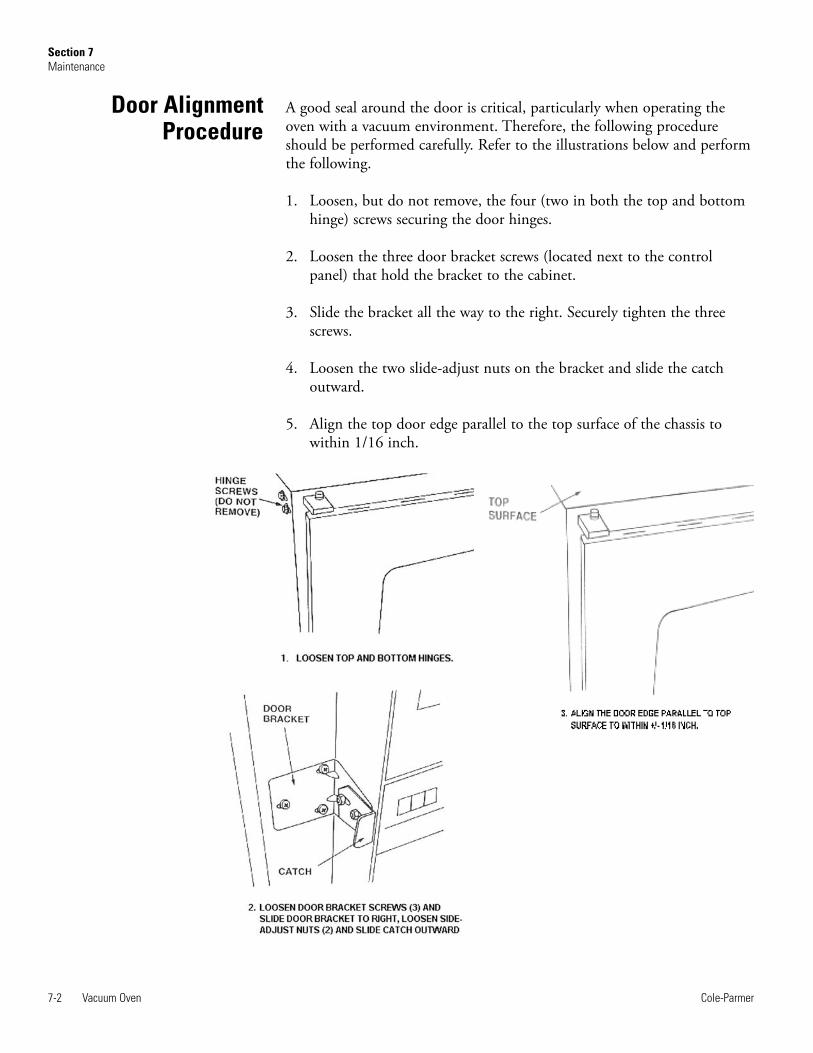
Door AlignmentProcedure
A good seal around the door is critical, particularly when operating theoven with a vacuum environment. Therefore, the following procedureshould be performed carefully. Refer to the illustrations below and performthe following.
1. Loosen, but do not remove, the four (two in both the top and bottomhinge) screws securing the door hinges.
2. Loosen the three door bracket screws (located next to the controlpanel) that hold the bracket to the cabinet.
3. Slide the bracket all the way to the right. Securely tighten the threescrews.
4. Loosen the two slide-adjust nuts on the bracket and slide the catchoutward.
5. Align the top door edge parallel to the top surface of the chassis towithin 1/16 inch.

Vacuum Oven 7-3Cole-Parmer
Section 7Maintenance
Door AlignmentProcedure (cont.)
6. Draw a vacuum by pressing on both left and right sides of the doorusing your hands. Close vacuum valve at 25 inches of Hg.
7. Tighten the two bolts for each hinge while lightly pressing each cornerof the door in the area of the hinge being tightened.
8. Slide the cam assembly to engage the catch, and then turn the handledown so that the flat on the cam is vertical. Push gently on the catchuntil it touches the flat on the cam.
9. Insert a 1/32-inch thick shim (not supplied) between the catch and flatside of cam, and securely tighten the two nuts on the catch whileapplying vacuum.
10. Remove the shim. Then release vacuum and open door.
11. Try cam mechanism for clearance of both door edge and cam. If thereis a clearance of more than 1/16 inch between the end of the cam andcatch projection, adjust spacing by loosening the three catch screwsand readjust catch.
12. Secure the three screws and check clearance of Step 11. Check thatoven door positively seals after completion of this procedure.


Section 8 Service
Caution Only trained personnel should perform service on this oven. s
Correcting a malfunction in the Oven primarily involves replacing thedefective component. Components that can be replaced are listed underTable 11 in Replacement Parts. Most components can be accessed byremoving the right side panel. There are six screws that hold the panel tothe oven chassis.
Heater replacement is a much larger task, requiring near completedisassembly of the oven by two persons. Therefore it is recommended thatwhen required, heaters be replaced by returning the oven to a servicecenter. It should be noted that, because of the very low watt density of theheater elements, an almost indefinite life is expected.
Because the Oven is equipped with self-diagnostic features, the servicerecommendations here are limited to the Trouble Analysis Chart shownbelow which incorporates these features. To use this chart effectively, selectthe Symptom category(s) that best describes the observable malfunction, inparticular the error codes. Proceed to inspect the Probable Causedescription(s) and take the necessary Corrective Action.
Vacuum Oven 8-1Cole-Parmer

8-2 Vacuum Oven Cole-Parmer
Section 8Service
Table 10: Trouble Analysis Chart
Symptom Probable Cause Corrective Action
Oven does not heat. CRC error. Error found in calibration data. Recalibrate unit.
Oven does not heat. OTC error. Open Control Thermocouple Check T.C. continuity; replace if open.
Oven does not heat. Open triac Check triac located on large heatsink.
Oven heaters Check resistance of each heating element. Resistance should bebetween 14.00 and 17.12 Ohms. Replace if defective.
Heater power turned off duringprogram execution. Enter Program Edit Mode. Check current step for heater operation.
Oven does not heat. OVR error. Open safety sentinel Push RESET button on sentinel. Replace sentinel if unable to reset.Sentinel is preset to trigger when heater temperature exceedsapproximately 300°C.
Pressure readout indicates wrongpressure Calibration incorrect. Perform Calibration procedure in this manual.
Offset value incorrect. Change offset so display value matches actual chamber pressure.
Temperature readout indicateswrong temperaature Calibration incorrect. Perform Calibration procedure in this manual
Offset value incorrect. Change offset so display value matches actual temperature.
Vacuum readout indicates atmos-pheric pressure with vacuum beingdrawn on the oven.
PURGE valve open. Close PURGE valve.
VACUUM valve closed. Open VACUUM valve.
Faulty door seal. Regrease or replace seal.
Internal tygon tubing betweeninlet port and vacuum sensordisconnected.
Reconnect tubing.
Door improperly aligned. Realign door following instruction given in this manual.

The replacement part descriptions and their corresponding numbers areprovided below. Note that parts information is only valid at thepublication date (see front cover of this manual), and subsequent revisionsmay have occurred after publication.
Vacuum Oven 8-3Cole-Parmer
Section 8Section title
Replacement Parts
Description Part Number
Control P.C. Board (115/230V) CP103305
Power Switch (S1) CP102627
Heater (HTR1, HTR2) CP50098
Triac (Q1) CP52563
Thermostat CP52018
Control Thermocouple (TC1) CP52025
Readout Thermocouple (TC2) 255036
Seal Replacement Kit CP70435
Shelf CP52002
Valve (Vacuum or Purge) CP44342
Handle CP44342
Cam CP02371
Hose Connector CP52062


Vacuum Oven 9-1Cole-Parmer
115V Schematic
230V Schematic


Cole-Parmer625 East Bunker CourtVernon Hills, IL 60061-98721-800-323-43401-847-549-7600www.coleparmer.com