Embed Size (px)
Citation preview
EMMA Design and Construction
Bruno Muratori
STFC, Daresbury Laboratory
21/01/09

The EMMA Project
• EMMA (Electron Machine with Many Applications) is a design for a non-scaling FFAG – the world’s first
• Collaboration of : BNL, CERN, CI, FNAL, JAI, LPSC Grenoble, STFC, TRIUMF
• Part of BASROC (British Accelerator Science and Radiation Oncology Consortium) / CONFORM (COnstruction of a Non-scaling FFAG for Oncology, Research and Medicine)
• Advantages:– Linear fixed field magnets: large dynamic aperture– Cheaper
• Disadvantages:– Novel longitudinal & transverse dynamics– Rapid tune variations: multiple resonance crossings
• Many potential applications– Driver for ADSR, µ acceleration, medical (e.g. PAMELA)

INJECTION LINE ALICE to EMMA
New Dipoles x 2 (33°) & BPMs at dipole entrancePosition measurement
New Dipole 30°& BPMs at dipole entrancePosition measurement
BPMPositionmeasurement
Wall Current Monitor
New Quadrupoles x 13
Ion Pump
Vacuum valve
Tomography SectionScreens x 3(emittance measurement)
SRS Quadrupoles x 3
Screen &Vert. Slit
Beam
Dire
ction
SRS Quadrupoles x 2
Screen
Vacuum valve
Screen
Emittance measurement
Current measurement
EMMARing
ALICE
• Match the probe beam to the requirements of EMMA
• Measure the properties of the probe beam

Diagnostics – injection line
• OTR Screen in ALICE before extraction dipole• BPMs @ entrance of every dipole in injection line• Straight ahead Faraday cup to measure charge & energy spread• OTR screen in dogleg for bunch length & energy measurement• Tomography section: 60 degrees phase advance per screen with
three screens for projected transverse emittance measurements and profiles
• Last dispersive section:– OTR screen & vertical slit in middle of first section together with– OTR screen in final section for energy and energy spread
measurements– Vertical steerers for position & angle before ring (to be used
with kickers for steering)– BPM at entrance of EMMA ring for position before entering
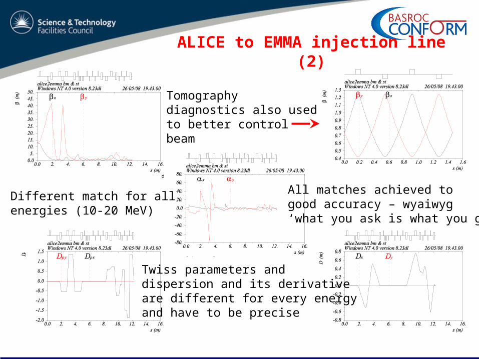
ALICE to EMMA injection line (2)
Tomographydiagnostics also usedto better controlbeam
Twiss parameters anddispersion and its derivativeare different for every energyand have to be precise
Different match for allenergies (10-20 MeV)
All matches achieved togood accuracy – wyaiwyg‘what you ask is what you get’
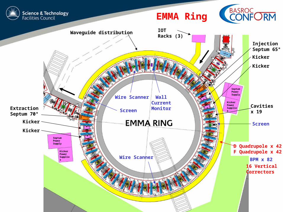
Injection Septum 65°
Kicker
Kicker
Cavities x 19
Extraction Septum 70°
Kicker
Kicker
Screen
Wire Scanner
Wall Current Monitor
Wire Scanner
Screen
BPM x 82
D Quadrupole x 42F Quadrupole x 42
16 Vertical Correctors
IOT Racks (3)
Waveguide distribution
EMMA Ring
KickerPowerSupplies
SeptumPowerSupply
SeptumPowerSupply
KickerPowerSupplies
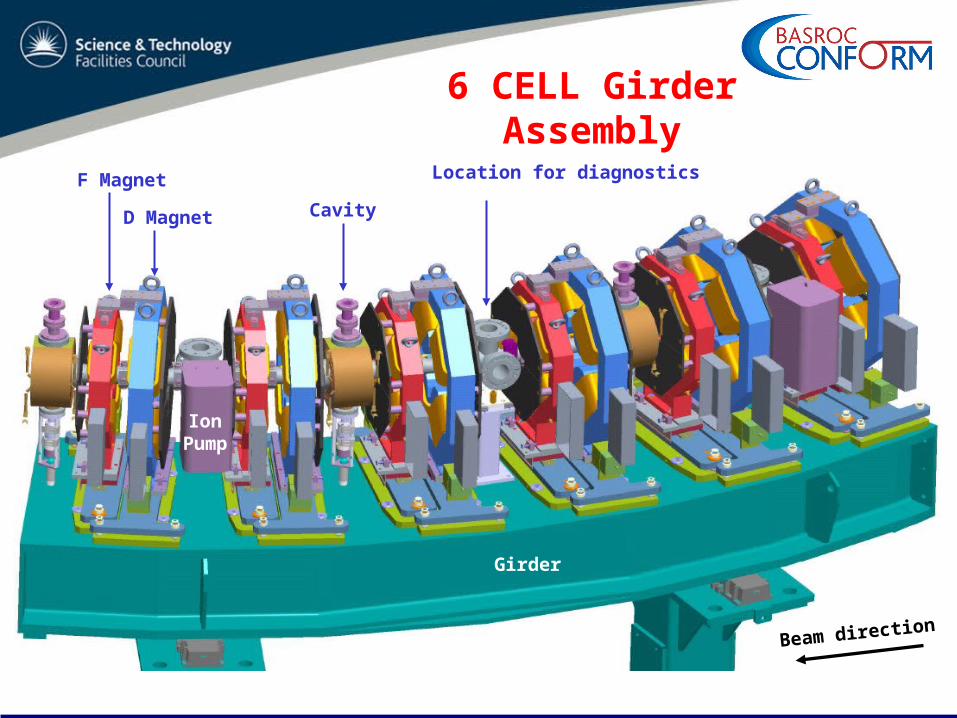
6 CELL Girder Assembly
IonPump
CavityD Magnet
F Magnet Location for diagnostics
Beam direction
Girder
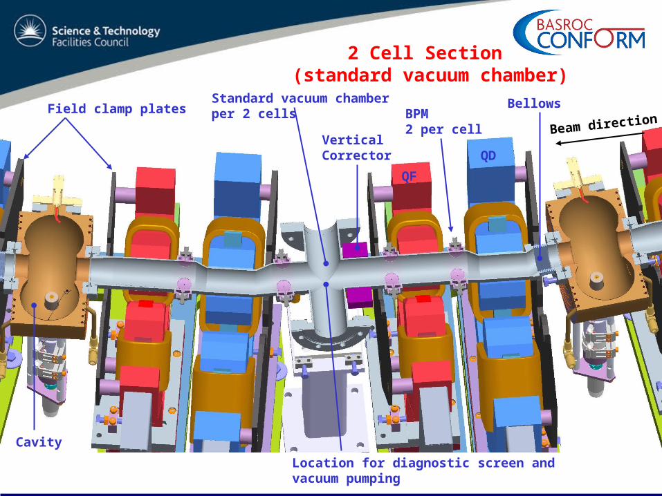
2 Cell Section (standard vacuum chamber)
Cavity
QD
QF
Vertical Corrector
BPM2 per cell Beam direction
BellowsStandard vacuum chamberper 2 cellsField clamp plates
Location for diagnostic screen andvacuum pumping
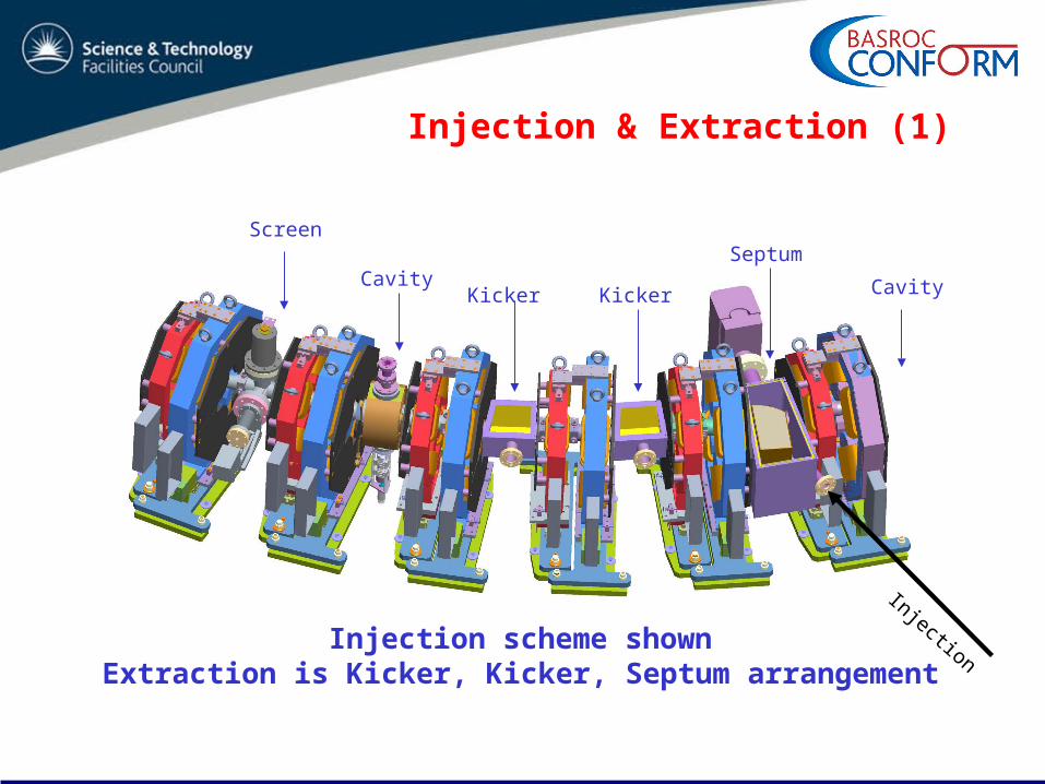
Injection & Extraction (1)
Kicker Kicker
Septum
CavityCavity
Injection
Screen
Injection scheme shownExtraction is Kicker, Kicker, Septum arrangement
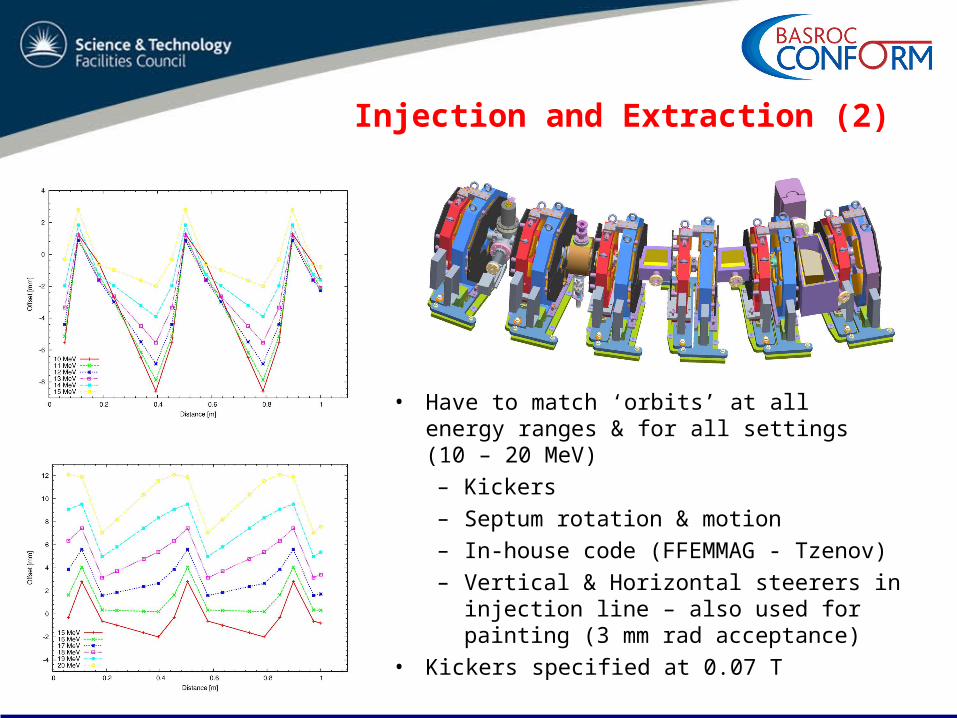
Injection and Extraction (2)
• Have to match ‘orbits’ at all energy ranges & for all settings (10 – 20 MeV)
– Kickers
– Septum rotation & motion
– In-house code (FFEMMAG - Tzenov)
– Vertical & Horizontal steerers in injection line – also used for painting (3 mm rad acceptance)
• Kickers specified at 0.07 T
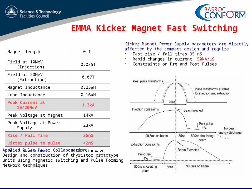
EMMA Kicker Magnet Fast Switching
Magnet length 0.1m
Field at 10MeV (Injection) 0.035T
Field at 20MeV (Extraction) 0.07T
Magnet Inductance 0.25H
Lead Inductance 0.16H
Peak Current at 10/20MeV 1.3kA
Peak Voltage at Magnet 14kV
Peak Voltage at Power Supply
23kV
Rise / Fall Time 35nS
Jitter pulse to pulse >2nS
Pulse Waveform Half Sinewave
Kicker Magnet Power Supply parameters are directlyaffected by the compact design and require:• Fast rise / fall times 35 nS• Rapid changes in current 50kA/S• Constraints on Pre and Post Pulses
Applied Pulse Power CollaborationDesign and construction of thyristor prototype units using magnetic switching and Pulse Forming Network techniques
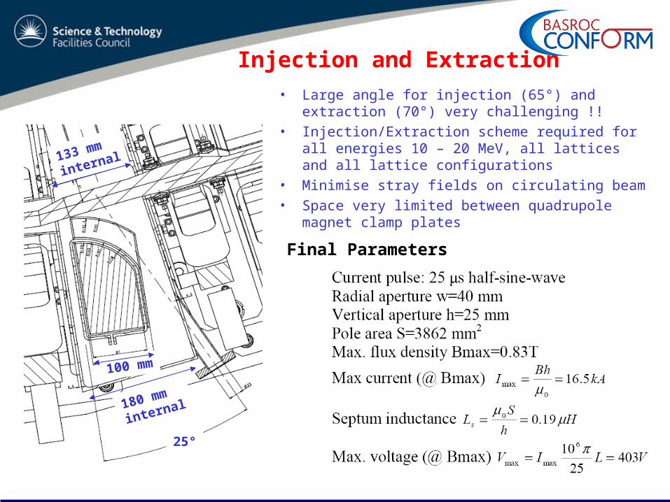
Injection and Extraction
133 mm
internal
100 mm
25°
180 mm
internal
Final Parameters
• Large angle for injection (65°) and extraction (70°) very challenging !!
• Injection/Extraction scheme required for all energies 10 – 20 MeV, all lattices and all lattice configurations
• Minimise stray fields on circulating beam• Space very limited between quadrupole magnet
clamp plates
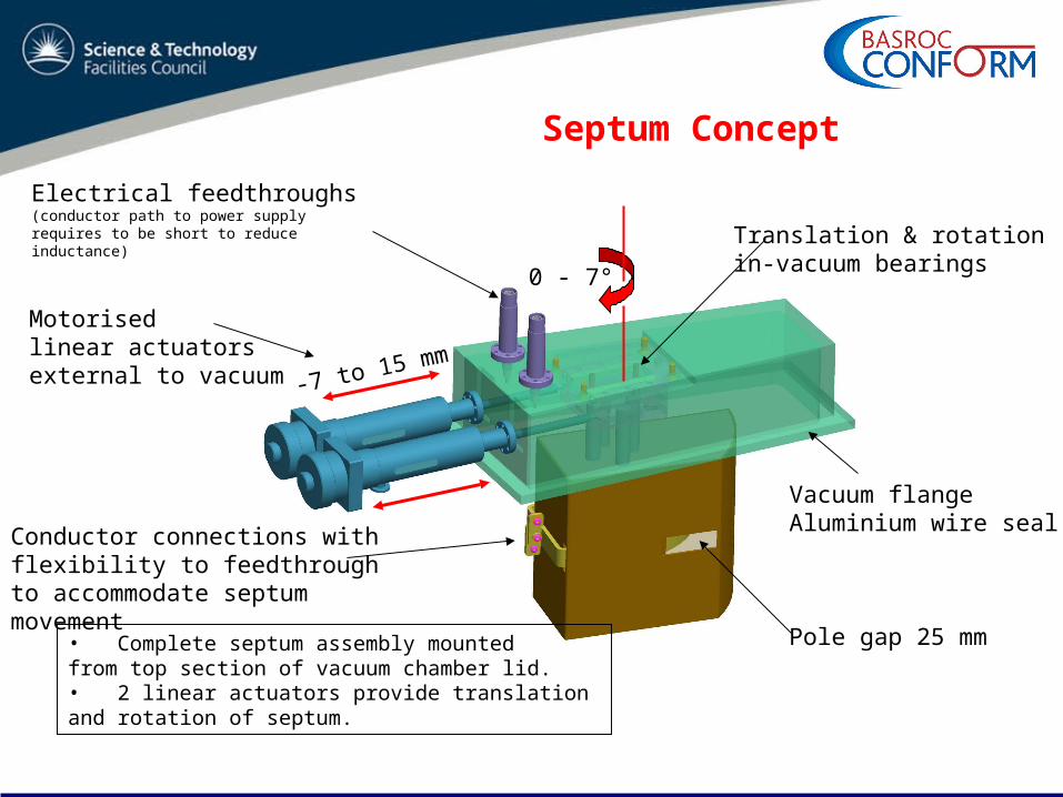
Septum Concept
Motorisedlinear actuatorsexternal to vacuum
Electrical feedthroughs (conductor path to power supply requires to be short to reduce inductance)
Vacuum flangeAluminium wire seal
Translation & rotationin-vacuum bearings
Conductor connections with flexibility to feedthrough to accommodate septum movement
Pole gap 25 mm• Complete septum assembly mounted from top section of vacuum chamber lid.• 2 linear actuators provide translation and rotation of septum.
-7 to 15 mm
0 - 7°
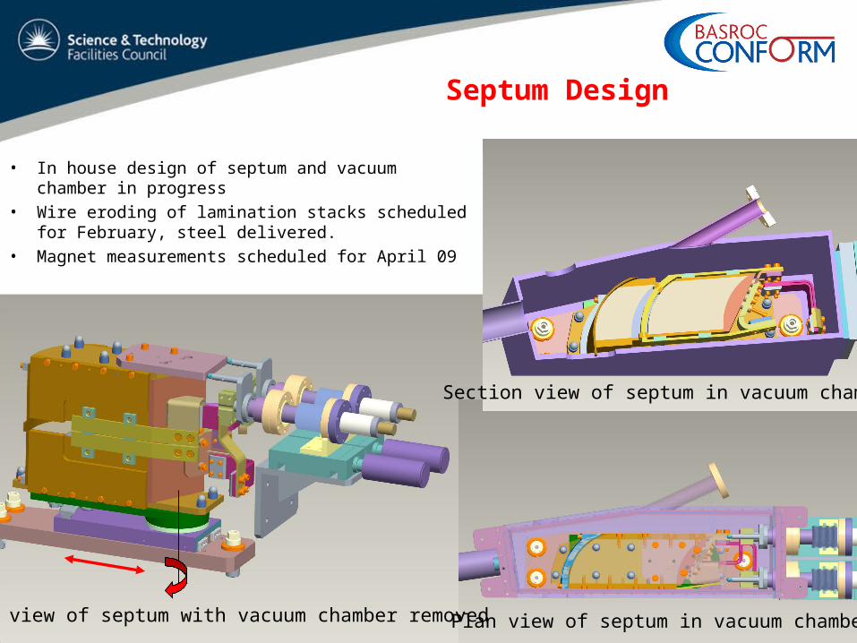
Septum Design
• In house design of septum and vacuum chamber in progress
• Wire eroding of lamination stacks scheduled for February, steel delivered.
• Magnet measurements scheduled for April 09
Plan view of septum in vacuum chamber
Section view of septum in vacuum chamber
ISO view of septum with vacuum chamber removed
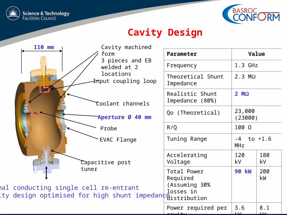
Cavity Design
Normal conducting single cell re-entrant cavity design optimised for high shunt impedance
Capacitive post tuner
Probe
Coolant channels
Input coupling loop
EVAC Flange
Aperture Ø 40 mm
110 mmParameter Value
Frequency 1.3 GHz
Theoretical Shunt Impedance
2.3 M
Realistic Shunt Impedance (80%)
2 M
Qo (Theoretical) 23,000 (23000)
R/Q 100 Ω
Tuning Range -4 to +1.6 MHz
Accelerating Voltage 120 kV 180 kV
Total Power Required(Assuming 30% losses in distribution
90 kW 200 kW
Power required per cavity
3.6 kW 8.1 kW
Cavity machined form 3 pieces and EB welded at 2 locations
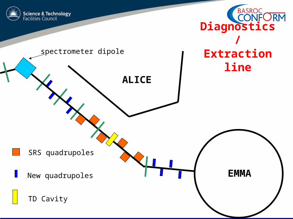
ALICE
EMMA
SRS quadrupoles
New quadrupoles
TD Cavity
spectrometer dipoleDiagnostics /
Extraction line

NEW DIAGNOSTICS BEAMLINE LAYOUTSpectrometer BPM @ dipole entranceScreenFaraday Cup
E-O Monitor
Screen x 3Tomography Section
Wall Current Monitor
BPM & Valve
SRS Quadrupoles x 6
New Quadrupoles x 4
ALICE
New Dipoles (43°) & BPMs at dipole entrance
Current measurement Longitudinal profile
Position measurement
New Quadrupoles x 4
Screen& Vert. Slit
Emittance measurement
Extracted momentum
Location for Transverse Deflecting Cavity(NOT IN BUDGET)
Screen
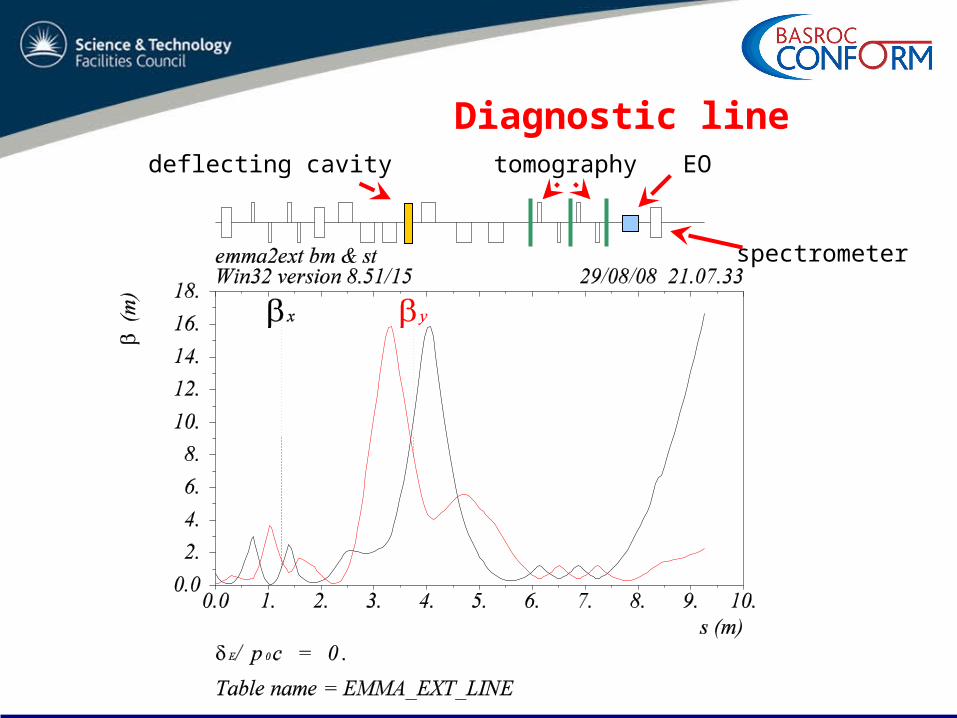
Diagnostic linedeflecting cavity tomography EO
spectrometer

Measurements
• Energy– First dipole & spectrometer at end with OTRs
• Projected transverse emittance– Quadrupole scans & tomography 60° phase advance / screen– Equivalent set-up in injection line for comparisons
• Bunch length– EO monitor downstream of the tomography section– No profile information
• Possibility of introducing a transverse deflecting cavity (TDC) to measure additional bunch properties

σz
L
0x
x
deflecting voltage
deflector bunch
screen
z
TDC Resolution (1)
• In absence of quadrupoles resolution increases with distance (L) from TDC to screen

σz
x
deflecting voltage
deflector bunch
screen
z
TDC Resolution (2)
• In the presence of interspersed quadrupoles this is not so and we must take into account of the entire transfer matrix from TDC to screen – there can be as many quadrupoles as desired
01 11 12''01 21 22
xx R R
xx R R
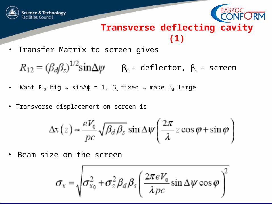
• Transverse displacement on screen is
• Beam size on the screen
• Transfer Matrix to screen gives
βd – deflector, βs – screen
• Want R12 big → sinΔψ = 1, βs fixed → make βd large
Transverse deflecting cavity (1)
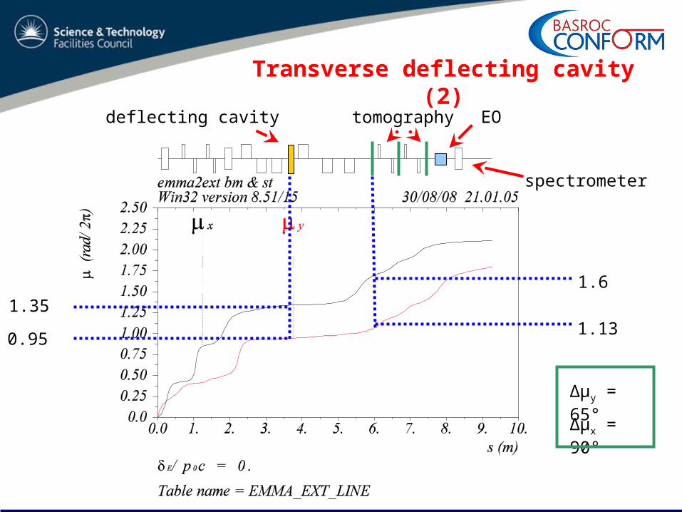
Transverse deflecting cavity (2)
deflecting cavity tomography EO
spectrometer
0.95
1.35
1.6
Δµx = 90°
Δµy = 65°
1.13
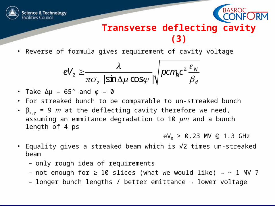
Transverse deflecting cavity (3)
• Reverse of formula gives requirement of cavity voltage
• Take Δµ = 65° and φ = 0• For streaked bunch to be comparable to un-streaked bunch
• βx,y = 9 m at the deflecting cavity therefore we need, assuming an emmitance degradation to 10 µm and a bunch length of 4 ps
eV0 ≥ 0.23 MV @ 1.3 GHz
• Equality gives a streaked beam which is √2 times un-streaked beam– only rough idea of requirements– not enough for ≥ 10 slices (what we would like) → ~ 1 MV ?– longer bunch lengths / better emittance → lower voltage
20 0| sin cos |
N
z d
eV pcm c

Measurements with TDC
• Slice emittance & transverse profiles given by
– knowledge of R12 from TDC to screen
– one dimension on screen gives slice emittance– other dimension gives bunch length
• Slice energy spread given by– streaked beam and spectrometer
12 sind sR 01 11 12''01 21 22
xx R R
xx R R
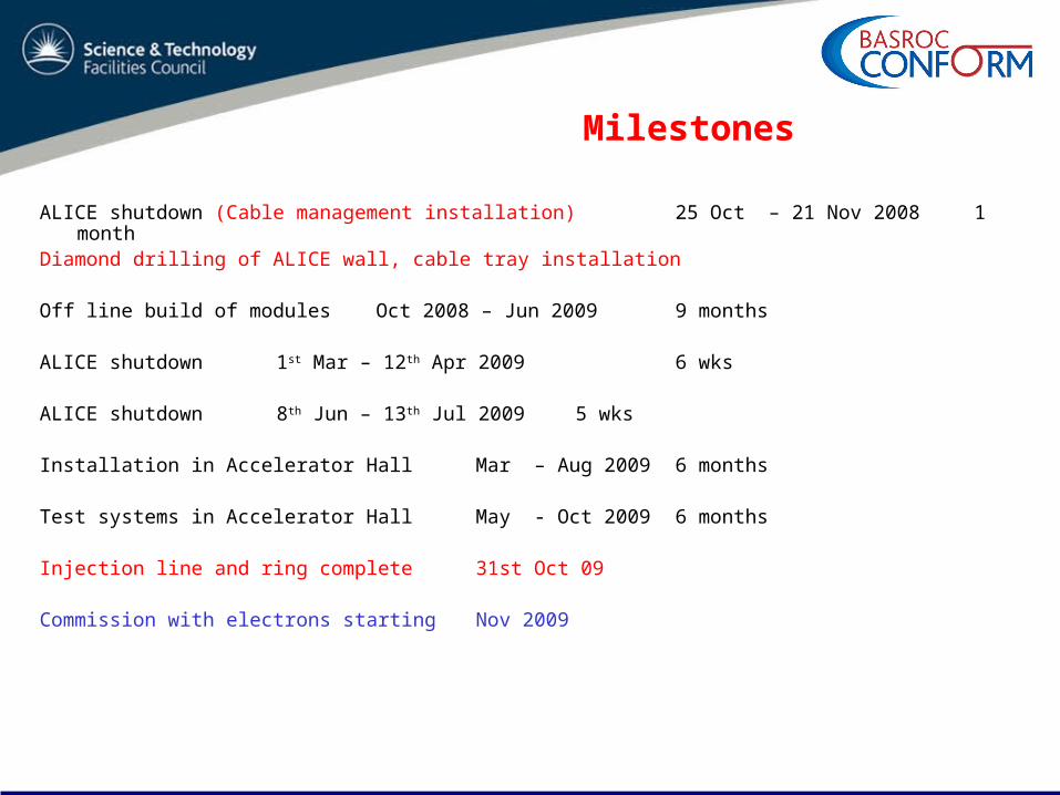
Milestones
ALICE shutdown (Cable management installation) 25 Oct – 21 Nov 2008 1 monthDiamond drilling of ALICE wall, cable tray installation
Off line build of modules Oct 2008 – Jun 2009 9 months
ALICE shutdown 1st Mar – 12th Apr 2009 6 wks
ALICE shutdown 8th Jun – 13th Jul 2009 5 wks
Installation in Accelerator Hall Mar – Aug 2009 6 months
Test systems in Accelerator Hall May - Oct 2009 6 months
Injection line and ring complete 31st Oct 09
Commission with electrons starting Nov 2009

Conclusions
• All components of injector line ordered (most already at DL)• Order for Extraction / Diagnostic line to go out soon• Very Challenging & exciting project !• Good characterisation of the beam at injection & extraction even
without TDC• Have good location for TDC should it be used in the future
– Realistic voltage parameters– Extra beam properties not available with EO– Currently looking at requirements for TDC with RF engineers
• Aim to be commissioning with electrons at DL in November 2009• Aim to demonstrate that non scaling FFAG technology works and
compare results with the theoretical studies performed to gain real experience of operating such accelerators
Acknowledgements
• All the EMMA team
– Internal staff
– Collaborators