Embed Size (px)
Citation preview
EMISSIONS FROM A 6.5L HMMWV ENGINE ONLOW SULFUR DIESEL FUEL AND JP-8
INTERIM REPORTTFLRF No. 376
byEdwin A. Frame
Matthew G. Blanks
U.S. Army TARDEC Fuels and Lubricants Research Facility(SwRI®) Southwest Research Institute®
San Antonio, TX
ForU.S. Army Corps of Engineers
Construction Engineering & Research LaboratoryChampaign, IL
Under Contract toU.S. Army TARDEC
Petroleum and Water Business AreaWarren, MI
Contract No. DAAE-07-99-C-L053 (WD11)
Approved for public release: distribution unlimited
December 2004
AD A
Disclaimers
The findings in this report are not to be construed as an official Department of the Army positionunless so designated by other authorized documents.
Trade names cited in this report do not constitute an official endorsement or approval of the useof such commercial hardware or software.
DTIC Availability Notice
Qualified requestors may obtain copies of this report from the Defense Technical InformationCenter, Attn: DTIC-OCC, 8725 John J. Kingman Road, Suite 0944, Fort Belvoir, Virginia 22060-6218.
Disposition Instructions
Destroy this report when no longer needed. Do not return it to the originator.
EMISSIONS FROM A 6.5L HMMWV ENGINE ONLOW SULFUR DIESEL FUEL AND JP-8
INTERIM REPORTTFLRF No. 376
byEdwin A. Frame
Matthew G. Blanks
U.S. Army TARDEC Fuels and Lubricants Research Facility (SwRI®)Southwest Research Institute
San Antonio, TX
ForU.S. Army Corps of Engineers
Construction Engineering & Research LaboratoryChampaign, IL
Under Contract toU.S. Army TARDEC
Petroleum and Water Business AreaWarren, MI
Contract No. DAAE-07-99-C-L053 (WD11)
Approved for public release: distribution unlimited
December 2004
Approved by:
Edwin C. Owens, DirectorU.S. Army TARDEC Fuels and LubricantsResearch Facility (SwRI)
AD A
REPORT DOCUMENTATION PAGEForm ApprovedOMB No. 0704-0188
Public reporting burden for this collection of information is estimated to average 1 hour per response, including the time for reviewing instruction, searching existingdata sources, gathering and maintaining the data needed, and completing and reviewing the collection of information. Send comments regarding this burdenestimate or any other aspect of this collection of information, including suggestions for reducing this burden, to Washington Headquarters Services, Directorate forInformation Operations and Reports, 1215 Jefferson Davis Highway, Suite 1204, Arlington, VA 22202-4302, and to the Office of Management and Budget, PaperworkReduction Project (0704-0188), Washington, DC 20503.
1. AGENCY USE ONLY 2. REPORT DATEDecember 2004
3. REPORT TYPE AND DATES COVEREDInterim, February 2003 – December 2004
4. TITLE AND SUBTITLEEmissions from a 6.5L HMMWV Engine on Low Sulfur Diesel Fuel and JP-8
6. AUTHOR(S)Frame, E.A.and Blanks, M.G
5. FUNDING NUMBERS
DAAE-07-99-C-L-053WD 11
7. PERFORMING ORGANIZATION NAME(S) AND ADDRESS(ES)U.S. Army TARDEC Fuels and Lubricants Research Facility (SwRI)Southwest Research InstituteP.O. Drawer 28510San Antonio, Texas 78228-0510
8. PERFORMING ORGANIZATION REPORT NUMBER
TFLRF No. 376
9. SPONSORING/MONITORING AGENCY NAME(S) AND ADDRESS(ES)U.S. Army TACOM U.S. Army Corps of EngineersU.S. Army TARDEC Engine Research & Development CenterPetroleum and Water Business Area Construction Engineering Research LaboratoryWarren, MI 48397-5000 Champaign, IL 60826-9005
10. SPONSORING/MONITORING AGENCY REPORT NUMBER
11. SUPPLEMENTARY NOTES
12a. DISTRIBUTION/AVAILABILITY STATEMENTApproved for public release; distribution unlimited
12b. DISTRIBUTION CODE
13. ABSTRACT (Maximum 200 words)This project investigated the exhaust emissions produced at various operating conditions by the 6.5L diesel engine that is used to power the Army’s HMMWV.Compared to reference diesel fuel, the use of JP-8 fuel resulted in lower levels of NOx and particulate matter. Polycyclic aromatic hydrocarbons (PAH’s) werealso determined. The JP-8 produced lower levels of exhaust PAH’s than the low sulfur certification diesel fuel (LSCD) for most but not all PAH type
15. NUMBER OF PAGES22
14. SUBJECT TERMSExhaust Emissions Tactical Vehicle Diesel Fuel JP-8 Particulate matter (PM) NOxHMMWV PAH 6.5L Engine PAH ISO 8178EPA Off-road transient test cycle 16. PRICE CODE
17. SECURITYCLASSIFICATION OFREPORTUnclassified
18. SECURITYCLASSIFICATION OF THISPAGEUnclassified
19. SECURITY CLASSIFICATION OFABSTRACT
Unclassified
20. LIMITATION OFABSTRACT
NSN 7540-01-280-5500 Standard Form 298 (Rev. 2-89)Prescribed by ANSI Std. Z39-18
298-102
v
EXECUTIVE SUMMARY
Emissions from tactical vehicle engines contribute to local and regional particulate matter (PM)air pollution. Emissions from these sources are not well understood, and the U.S. Army requiresmethods/models to predict PM10 and PM2.5 emissions from these military-unique sources. Todevelop these methods/models, the mass and chemical speciation of tactical vehicle engineemissions need to be characterized. This project investigated the exhaust emissions produced atvarious operating conditions by the 6.5L diesel engine that is used to power the Army’sHMMWV. Compared to reference diesel fuel, the use of JP-8 fuel resulted in lower levels ofNOx and particulate matter.
vi
FOREWARD/ACKNOWLEDGMENTS The U.S. Army TARDEC Fuels and Lubricants Research Facility (TFLRF) located at Southwest
Research Institute (SwRI), San Antonio, Texas, performed this work during the period February 2003
through December 2004 under Contract No. DAAE-07-99-C-L053. The work was funded by the U.S.
Army Corps of Engineers, Construction Engineering Research laboratory (CERL), Champaign, Illinois.
The U.S. Army Tank-Automotive RD&E Center, Petroleum and Water Business Area, Warren, Michigan
administered the project. Mr. Luis Villahermosa (AMSTA-RBFF) served as the TARDEC contracting
officer’s technical representative. Mr. Mike Kemme served as the project technical monitor.
Test results presented in this report were generated by the Department of Emissions Research (DER),
Automotive Products and Emissions Research of Southwest Research Institute (SwRI), for the U.S. Army
TARDEC Fuels and Lubricants Research Facility/SwRI (TFLRF),. This work was conducted under the
DER management of Mr. Terry L. Ullman, Mr. John J. Elizondo, Staff Technician, Mr. Juan G. Vega,
Technician, and Mr. Rodney E. Grinstead provided primary technical support. The authors wish to
acknowledge the administrative and report-processing support provided by Linda De Salme.
vii
TABLE OF CONTENTS
Section Page 1.0 INTRODUCTION and OBJECTIVE ...............................................................................1 2.0 PROCEDURE...................................................................................................................1 2.1 Installation and Break-In..........................................................................................2 2.2 Test Fuels .................................................................................................................2 2.3 Emission Testing......................................................................................................4 3.0 RESULTS .........................................................................................................................7
3.1 Regulated Exhaust Emissions3.1.1 Sample of Emission Data Analysis Technique for 11 Steady-State
Modes........................................................................................................73.2 Actual and Estimated Results ..................................................................................8
3.2.1 Steady-State 11 Mode Results ..................................................................83.2.2 Nonroad Transient Cycle (SAT) Results ..................................................83.2.3 PAH Emissions .......................................................................................17
4.0 SUMMARY....................................................................................................................20 5.0 REFERENCES ...............................................................................................................22
LIST OF TABLES Table Page 1. Test Plan for Accumulating Emissions Data from GM 6.5L Heavy-Duty
Diesel Engine ....................................................................................................................3 2. Low Sulfur Certification Diesel Properties.......................................................................5 2A. Properties of JP-8, AL-26936 (CL03-0002) .........................................................6 3. List of Measured Emissions and Analytical Methods ......................................................74. Modal and Composite Emission Rates from GM 6.5L Engine for 11 Steady-State
Modes using LSCD and JP-8..........................................................................................13 4A. Emission Results from a 6.5L GM Heavy-Duty Diesel Engine .........................14 5. Torque Maps from a 2002 GM 6.5L Heavy-Duty Diesel Engine using Two Fuels.......16 6. Transient Emission Rates from GM 6.5L Engine for SAT Nonroad Tests using JP-8 ..17 7. PAH Identification ..........................................................................................................19 8. Speed and Load for each Mode ......................................................................................199. Summary of Emission Results from GM 6.5L Engine for 11-Mode Steady-State and
SAT Transient Nonroad Tests using LSCD and JP-8.....................................................21
viii
LIST OF ILLUSTRATIONS
Figure Page 1. Installed 2002 GM 6.5L Heavy-Duty Engine...................................................................4 2. Average NOx Emission Rates from GM 6.5L Engine for 11 Steady-State Modes using
LSCD and JP-8 (Straight-Line Connector).......................................................................9 3. Average NOx Emission Rates from GM 6.5L Engine for 11 Steady-State Modes using
LSCD and JP-8 (Smoothed-Line Connector) ...................................................................9 4. Average and Estimated NOx Emission Rates from GM 6.5L Engine for 11 Steady-State
Modes using LSCD and JP-8 (Smoothed-Line Connector)............................................10 5. Average HC Emission Rates from GM 6.5L Engine for 11 Steady-State Modes using
LSCD and JP-8 (Straight-Line Connector).....................................................................10 6. Average and Estimated HC Emission Rates from GM 6.5L Engine for 11 Steady-State
Modes using LSCD and JP-8 (Smoothed-Line Connector)............................................11 7. Average CO Emission Rates from GM 6.5L Engine for 11 Steady-State Modes using
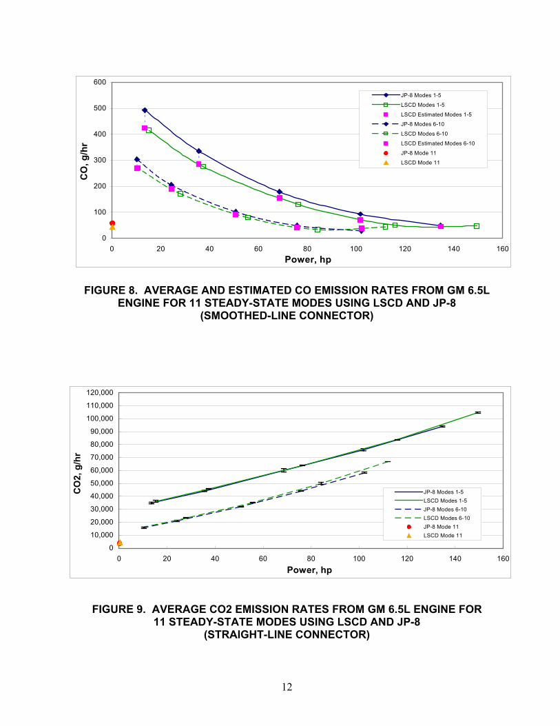
LSCD and JP-8 (Straight-Line Connector).....................................................................11 8. Average and Estimated CO Emission Rates from GM 6.5L Engine for 11 Steady-State
Modes using LSCD and JP-8 (Smoothed-Line Connector)............................................12 9. Average CO2 Emission Rates from GM 6.5L Engine for 11 Steady-State Modes using
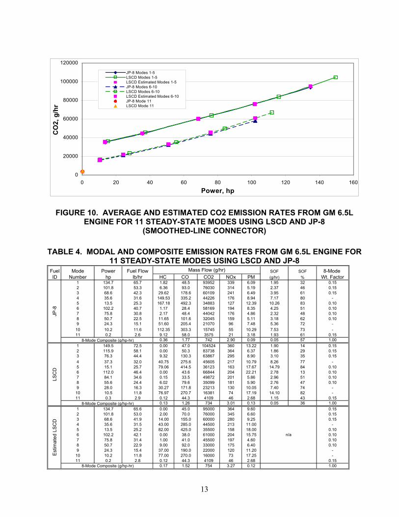
LSCD and JP-8 (Straight-Line Connector).....................................................................12 10. Average and Estimated CO2 Emission Rates from GM 6.5L Engine for 11 Steady-State
Modes using LSCD and JP-8 (Smoothed-Line Connector)............................................1311. Transient Torque Maps on Two Fuels from a 2002 GM 6.5L Heavy-Duty
Diesel Engine ..................................................................................................................15 12. Exhaust Emissions Nonroad Transient Test Cycle (SAT)..............................................17 13. PAH’S by Test Cycle......................................................................................................18 14. PAH-2 .............................................................................................................................20 15. Weighted 8-Mode Exhaust Emissions ............................................................................21 16. BAP Emission from Particulate Matter ..........................................................................22 APPENDICES A. GM Heavy-Duty Diesel Engine Specifications B. Break-In Instructions
C. 11-Mode Steady-State Emission Results from 6.5L GM Heavy-Duty Diesel Engineusing JP-8 and LSCD
D. SAT Nonroad Transient Emission Results from 6.5L GM Heavy-Duty DieselEngine using JP-8
E. Brake-Specific PAH’S
ix
SYMBOLS AND ABBREVIATIONS CFR Code of Federal Regulations DER Department of Emissions Research GM General Motors HMMWV High-Mobility Multipurpose Wheeled Vehicle hp Horse Power ISO International Standards Organization L Liter LSCD Low Sulfur Certification Diesel Fuel mm Millimeter NOx Oxides of Nitrogen PAH Polycyclic Aromatic Hydrocarbon PM Particulate Matter RPM Revolutions per Minute SwRI Southwest Research Institute TARDEC U.S. Army Tank-automotive RD & E Center TFLRF U.S. Army TARDEC Fuels and Lubricants Research Facility
1
1.0 INTRODUCTION and OBJECTIVE
Exhaust emissions from tactical vehicle engines contribute to local and regional air pollution. The
emissions from these sources are not well understood and the Army requires methods/models to
predict pollutant emissions from these military unique sources. To develop estimation
methods/models, the mass and chemical speciation of tactical vehicle engine emissions need to be
characterized. The characterization of these exhaust emissions may also be useful in a method to
determine the Army’s contribution to atmospheric pollution concentrations at receptor sites of
concern.
The objective of the proposed work was development of air pollutant emission factors for military
off-road sources that are accepted by regulators. Exhaust emissions from a tactical vehicle engine
were determined.
In the Army’s tactical/combat vehicle fleet, the HMMWV has both the largest population and
accumulates the most operation time. It is powered by a 4-stroke cycle, indirect injection (IDI)
diesel engine. IDI engines are known to produce higher levels of soot and particulate matter than
direct injected 4-stroke cycle diesel engines of the same size. For these reasons, the HMMWV was
selected by ERDC/CERL for the initial determination of exhaust emission factors. In this project,
exhaust emissions were collected from a 2002 model year 6.5L GM heavy-duty diesel engine that is
typical of those used in the HMMWV.
2.0 PROCEDURE
A new 2002 GM 6.5 liter, heavy-duty diesel engine (SN 2722) was used. Engine specifications are
given in Table A-1 of Appendix A. The test plan used for accumulating emissions data from the
engine is given in Table 1. The engine was initially operated on ASTM No. 2-D diesel fuel for a
100-hour "break-in" procedure. Then, JP-8 (AL-26936) and low sulfur certification diesel (LSCD,
EM-4816-F) were used in triplicate 11-mode steady-state tests for measurement of regulated
emissions. In addition, JP-8 was used in triplicate nonroad cycle testing over the San Antonio
Transient (SAT) cycle for measurement of regulated emissions.
2
2.1 Installation and "Break-In"
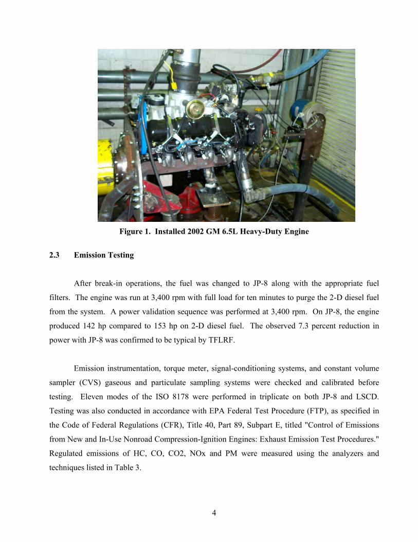
The engine was installed in transient capable Test Cell No. 3 as shown in Figure_1. The
installation included exhaust "Y" pipe fabrication, engine mount fabrication, and engine accessory
belt routing.
ASTM No. 2-D diesel fuel, EM-4747-F, was used for the 100-hour "break-in" procedure.
This procedure is outlined in Table B-1 of Appendix B. While setting intake and exhaust
restrictions DER encountered dynamometer failure. This failure was believed to be associated with
the high speed necessary to reach high idle (3,900 rpm) of the 6.5L engine. The dynamometer was
repaired and arrangements were made with TFLRF to limit the engine speed to 3,400 rpm for the
duration of the project.
The initial 1.5-hour portion of the break-in was run using factory fill oil contained in the
engine, as received. After the initial 1.5-hour portion, the engine oil was changed at 25, 50, and 75
hours using U.S. Army MIL-PRF-2104G reference engine oil of viscosity grade SAE 15W40 (AL-
26923). Engine oil at the 100-hour point of the "break-in" procedure was retained in the engine for
emission testing.
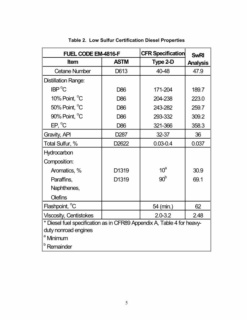
2.2 Test Fuels
Two fuels were used in emission testing of the GM 6.5L engine. JP-8 (AL-26936) was used
in three 11-mode steady-state tests and three nonroad transient SAT tests. Low sulfur certification
diesel (LSCD EM-4816-F) was used in three 11-mode steady-state tests. Properties for the LSCD
are listed in Table 2, and for JP-8 in Table 2A.
3
Table 1. Test Plan for Accumulating Emissions Datafrom GM 6.5L Heavy-Duty Diesel Engine
Step Description
1 Perform emission instrument calibrations as required. Calibrate torquemeter and checksignal-conditioning systems. Validate CVS gaseous and particulate sampling systemsusing propane recovery techniques.
2 Complete installation of 6.5L engine in transient-capable test cell.
3 Perform 100-hour break-in using 2D durability diesel fuel EM-4747-F (tank 18). Break-in procedure supplied by the TFLRF. Leave oil from last 25 hours of “break-in” inengine for testing.
4 Perform fuel change procedure to JP-8 fuel AL-26936, supplied by TFLRF. Change fuelfilters, purge fuel supply, etcetera.
5 Operate engine at rated speed and load for approximately ten minutes, then powervalidate engine.
6 Conduct ISO 8178 11-mode test three times using JP-8 fuel. Measure HC, CO, CO2,NOx, and PM on each mode.
7 Perform fuel change procedure to Low Sulfur Certification Diesel; (LSCD. EM-4816-F).Change fuel filters, purge fuel supply, etcetera.
8 Operate engine at rated speed and load for approximately ten minutes, then powervalidate engine.
9 Conduct ISO 8178 11-mode test three times using LSCD. Measure HC, CO, CO2, NOx,and PM on each mode.
10 Perform fuel change procedure to JP-8 fuel. Change fuel filters, purge fuel supply,etcetera.
11 Conduct transient full load torque-map from low to high idle. Use these results to createSAT non-road transient command cycle.
12 Conduct the SAT non-road transient test cycle three times. Measure HC, CO, CO2, NOx,and PM on each cycle using JP-8.
13 Report data.
4
Figure 1. Installed 2002 GM 6.5L Heavy-Duty Engine
2.3 Emission Testing
After break-in operations, the fuel was changed to JP-8 along with the appropriate fuel
filters. The engine was run at 3,400 rpm with full load for ten minutes to purge the 2-D diesel fuel
from the system. A power validation sequence was performed at 3,400 rpm. On JP-8, the engine
produced 142 hp compared to 153 hp on 2-D diesel fuel. The observed 7.3 percent reduction in
power with JP-8 was confirmed to be typical by TFLRF.
Emission instrumentation, torque meter, signal-conditioning systems, and constant volume
sampler (CVS) gaseous and particulate sampling systems were checked and calibrated before
testing. Eleven modes of the ISO 8178 were performed in triplicate on both JP-8 and LSCD.
Testing was also conducted in accordance with EPA Federal Test Procedure (FTP), as specified in
the Code of Federal Regulations (CFR), Title 40, Part 89, Subpart E, titled "Control of Emissions
from New and In-Use Nonroad Compression-Ignition Engines: Exhaust Emission Test Procedures."
Regulated emissions of HC, CO, CO2, NOx and PM were measured using the analyzers and
techniques listed in Table 3.
5
Table 2. Low Sulfur Certification Diesel Properties
CFR SpecificationItem ASTM Type 2-D
Cetane Number D613 40-48 47.9Distillation Range: IBP oC D86 171-204 189.7 10% Point, oC D86 204-238 223.0 50% Point, oC D86 243-282 259.7 90% Point, oC D86 293-332 309.2 EP, oC D86 321-366 358.3Gravity, API D287 32-37 36Total Sulfur, % D2622 0.03-0.4 0.037HydrocarbonComposition: Aromatics, % D1319 10a 30.9 Paraffins, D1319 90b 69.1 Naphthenes, OlefinsFlashpoint, oC 54 (min.) 62Viscosity, Centistokes 2.0-3.2 2.48
a Minimumb Remainder
* Diesel fuel specification as in CFR89 Appendix A, Table 4 for heavy-duty nonroad engines
FUEL CODE EM-4816-F SwRI Analysis
6
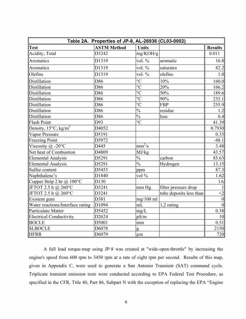
Table 2A. Properties of JP-8, AL-26936 (CL03-0002)Test ASTM Method Units ResultsAcidity, Total D3242 mg/KOH/g 0.011Aromatics D1319 vol. % aromatic 16.8Aromatics D1319 vol. % saturates 82.2Olefins D1319 vol. % olefins 1.0Distillation D86 °C 10% 160.0Distillation D86 °C 20% 166.2Distillation D86 °C 50% 189.6Distillation D86 °C 90% 235.1Distillation D86 °C FBP 255.9Distillation D86 % residue 1.2Distillation D86 % loss 0.4Flash Point D93 °C 41.39Density, 15°C, kg/m3 D4052 0.7930Vapor Pressure D5191 0.33Freezing Point D5972 -48.1Viscosity @ -20°C D445 mm2/s 3.48Net heat of Combustion D4809 MJ/kg 43.57Elemental Analysis D5291 % carbon 85.63Elemental Analysis D5291 % Hydrogen 13.15Sulfur content D5453 ppm 87.3Naphthalene’s D1840 vol % 1.62Copper Strip 2 hr @ 100°C D130 1AJFTOT 2.5 h @ 260°C D3241 mm Hg filter pressure drop 1JFTOT 2.5 h @ 260°C D3241 tube deposits less than <2Existent gum D381 mg/100 ml 0Water reactions/Interface rating D1094 mL 1,2 rating 0Particulate Matter D5452 mg/L 0.38Electrical Conductivity D2624 pS/m 10BOCLE D5001 mm 0.51SLBOCLE D6078 g 2150HFRR D6079 µm 720
A full load torque-map using JP-8 was created at "wide-open-throttle" by increasing the
engine's speed from 600 rpm to 3450 rpm at a rate of eight rpm per second. Results of this map,
given in Appendix C, were used to generate a San Antonio Transient (SAT) command cycle.
Triplicate transient emission tests were conducted according to EPA Federal Test Procedure, as
specified in the CFR, Title 40, Part 86, Subpart N with the exception of replacing the EPA “Engine
7
Dynamometer Schedule for Heavy-Duty Diesel Engines” given in the CFR, Title 40, Appendix I,
Subpart F(2) with the proposed San Antonio Transient (SAT) Engine Dynamometer Schedule.
Regulated emissions of HC, CO, CO2, NOx and PM were measured for each test using the
analyzers and techniques listed in Table 3.
Compound Abbreviation Analytical MethodHydrocarbon HC Heated Flame Ionization DetectorCarbon Monoxide CO Non-Dispersive Infrared AnalyzerCarbon Dioxide CO2 Non-Dispersive Infrared AnalyzerOxides of Nitrogen NOx Chemiluminescent AnalyzerParticulate Matter PM 90 mm Pallflex Filters
Table 3. List of Measured Emissions and Analytical Methods
3.0 RESULTS
Modal test work uses percent of full load. Because the full load performance on the LSCD fuel and
the JP-8 were different, the loads for the individual modes were different for the two fuels. All the
results are given as measured, but to ease comparison between the fuels at equal performance,
emissions using LSCD were estimated from the actual data for performance levels equivalent to that
obtained on JP-8. Therefore, results for modal test work are given for LSCD and JP-8 as measured
and for estimated LSCD for performance equivalent to JP-8.
3.1 Regulated Exhaust Emissions
3.1.1 Sample of Emission Data Analysis Technique for 11 Steady-State Modes
The three-test average of NOx mass emission rates for the 11 modes are given in Figure 2.
In addition, the deviation is also indicated. Detailed results are given in Appendix C.
Straight lines were simply used to connect Modes 1 through 5, run at 3,400 rpm; and Modes
6 through 10, run at 2,040 rpm, to highlight the relationships. Figure 3 also gives the NOx
mass emission rates for the 11 modes; however, this figure uses a smoothed line to connect
the modes to provide a means to better estimate emission levels between modes.
8
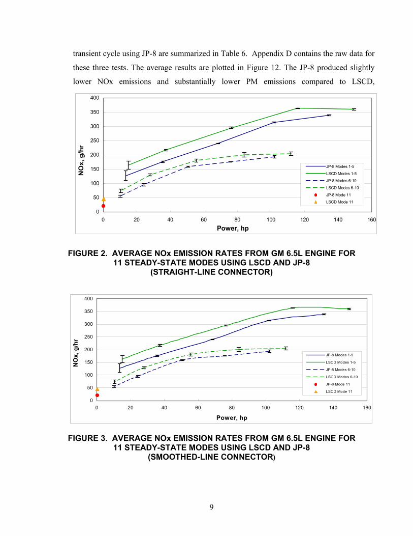
To compare the corresponding modal rate of emission results from each fuel, for each JP-8
power level, a projection from the JP-8 power level to the curve defining the LSCD
emission was made. The resulting point was taken to be the NOx level that would be
produced by LSCD at the same power achieved on JP-8. Figure 4 shows the estimated
LSCD NOx emission points for ease of comparison between the LSCD and JP-8. This
estimation technique was used to compare each of the emissions measured for the 11-mode
tests on both fuels.
3.2 Actual and Estimated Results
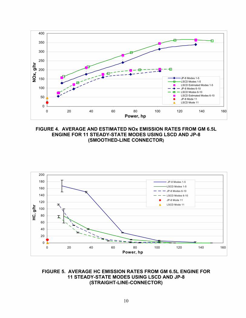
3.2.1 Steady-State 11 Mode Results
The graphs and tables in this section give the actual and estimated results for the pollutants
measured during the 11 mode tests. Results for HC, CO, CO2, NOx, and PM are given in
Figures 2 through 14. Results for Soluble organic fraction (SOF) of PM, in terms of percent,
are given in Figure 15. Appendix C contains the raw data for all 11-mode tests.
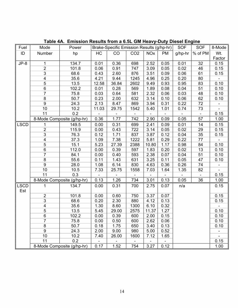
Table 4 lists the emission data for all 11 modes in grams/hour. The brake-specific emissions
data are presented in Table 4A. In addition, 8 of the 11 modes were used to compute 8-
mode composites using EPA modal weight factors given in the CFR 40, Part 89, for nonroad
engine emissions. Composite 8-mode results are also given in Table 4 for JP-8, LSCD and
the estimated LSCD points for comparison purposes. The following general trends were
observed:
• NOx-JP-8 consistently produced lower levels
• HC- JP-8 consistently produced higher levels
• CO- JP-8 consistently produced higher levels
• PM- Except for idle, JP-8 consistently produced lower levels
• SOF % of PM- In general, JP-8 produced a higher SOF % of PM.
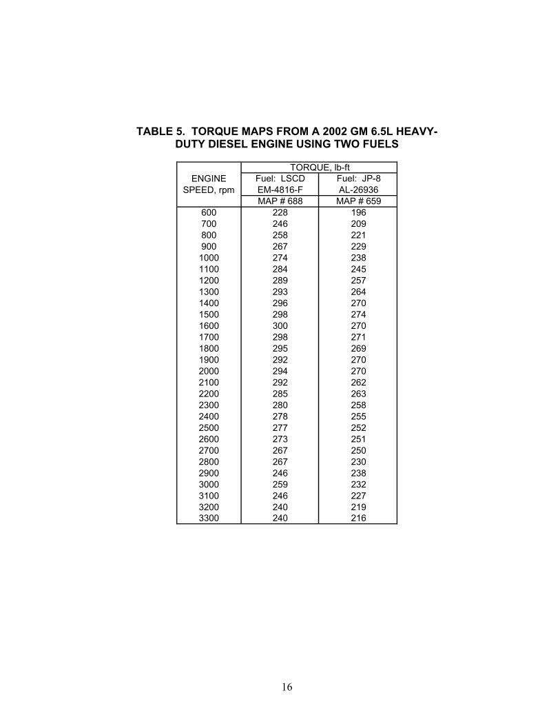
3.2.2 Nonroad Transient Cycle (SAT) Results
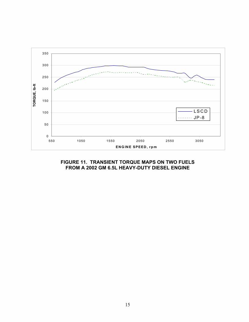
The SAT cycle was un-normalized using the torque-map data acquired from operating the
engine on JP-8 at full-load from idle speed to rated speed. Results from the torque map for
JP-8 are given in Figure 11 and Table 5. Results from the three runs of the SAT nonroad
9
transient cycle using JP-8 are summarized in Table 6. Appendix D contains the raw data for
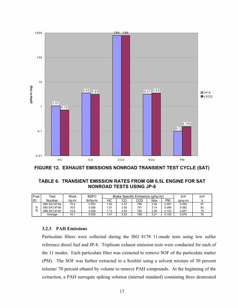
these three tests. The average results are plotted in Figure 12. The JP-8 produced slightly
lower NOx emissions and substantially lower PM emissions compared to LSCD,
0
50
100
150
200
250
300
350
400
0 20 40 60 80 100 120 140 160
Power, hp
NO
x, g
/hr
JP-8 Modes 1-5
LSCD Modes 1-5
JP-8 Modes 6-10
LSCD Modes 6-10
JP-8 Mode 11
LSCD Mode 11
FIGURE 2. AVERAGE NOx EMISSION RATES FROM GM 6.5L ENGINE FOR11 STEADY-STATE MODES USING LSCD AND JP-8
(STRAIGHT-LINE CONNECTOR)
0
50
100
150
200
250
300
350
400
0 20 40 60 80 100 120 140 160
Power, hp
NO
x, g
/hr
JP-8 Modes 1-5
LSCD Modes 1-5
JP-8 Modes 6-10
LSCD Modes 6-10
JP-8 Mode 11
LSCD Mode 11
FIGURE 3. AVERAGE NOx EMISSION RATES FROM GM 6.5L ENGINE FOR11 STEADY-STATE MODES USING LSCD AND JP-8
(SMOOTHED-LINE CONNECTOR)
10
0
50
100
150
200
250
300
350
400
0 20 40 60 80 100 120 140 160Power, hp
NO
x, g
/hr
JP-8 Modes 1-5LSCD Modes 1-5LSCD Estimated Modes 1-5JP-8 Modes 6-10LSCD Modes 6-10LSCD Estimated Modes 6-10JP-8 Mode 11LSCD Mode 11
FIGURE 4. AVERAGE AND ESTIMATED NOx EMISSION RATES FROM GM 6.5LENGINE FOR 11 STEADY-STATE MODES USING LSCD AND JP-8
(SMOOTHED-LINE CONNECTOR)
0
20
40
60
80
100
120
140
160
180
200
0 20 40 60 80 100 120 140 160Power, hp
HC
, g/h
r
JP-8 Modes 1-5
LSCD Modes 1-5
JP-8 Modes 6-10
LSCD Modes 6-10
JP-8 Mode 11
LSCD Mode 11
FIGURE 5. AVERAGE HC EMISSION RATES FROM GM 6.5L ENGINE FOR11 STEADY-STATE MODES USING LSCD AND JP-8
(STRAIGHT-LINE-CONNECTOR)
11
0
20
40
60
80
100
120
140
160
180
0 20 40 60 80 100 120 140 160Power, hp
HC
, g/h
r
JP-8 Modes 1-5LSCD Modes 1-5
LSCD Estimated Modes 1-5JP-8 Modes 6-10
LSCD Modes 6-10LSCDl Estimated Modes 6-10JP-8 Mode 11
LSCD Mode 11
FIGURE 6. AVERAGE AND ESTIMATED HC EMISSION RATES FROM GM 6.5LENGINE FOR 11 STEADY-STATE MODES USING LSCD AND JP-8
(SMOOTHED-LINE CONNECTOR)
0
50
100
150
200
250
300
350
400
450
500
550
0 20 40 60 80 100 120 140 160
Power, hp
CO
, g/h
r
JP-8 Modes 1-5
LSCD Modes 1-5
JP-8 Modes 6-10
LSCD Modes 6-10
JP-8 Mode 11
LSCD Mode 11
FIGURE 7. AVERAGE CO EMISSION RATES FROM GM 6.5L ENGINE FOR11 STEADY-STATE MODES USING LSCD AND JP-8
(STRAIGHT-LINE CONNECTOR)
12
FIGURE 8. AVERAGE AND ESTIMATED CO EMISSION RATES FROM GM 6.5LENGINE FOR 11 STEADY-STATE MODES USING LSCD AND JP-8
(SMOOTHED-LINE CONNECTOR)
0
10,000
20,000
30,000
40,000
50,000
60,000
70,000
80,000
90,000
100,000
110,000
120,000
0 20 40 60 80 100 120 140 160Power, hp
CO
2, g
/hr
JP-8 Modes 1-5LSCD Modes 1-5JP-8 Modes 6-10LSCD Modes 6-10JP-8 Mode 11LSCD Mode 11
FIGURE 9. AVERAGE CO2 EMISSION RATES FROM GM 6.5L ENGINE FOR11 STEADY-STATE MODES USING LSCD AND JP-8
(STRAIGHT-LINE CONNECTOR)
0
100
200
300
400
500
600
0 20 40 60 80 100 120 140 160Power, hp
CO
, g/h
rJP-8 Modes 1-5
LSCD Modes 1-5
LSCD Estimated Modes 1-5
JP-8 Modes 6-10
LSCD Modes 6-10
LSCD Estimated Modes 6-10
JP-8 Mode 11
LSCD Mode 11
13
0
20000
40000
60000
80000
100000
120000
0 20 40 60 80 100 120 140 160
Power, hp
CO
2, g
/hr
JP-8 Modes 1-5LSCD Modes 1-5LSCD Estimated Modes 1-5JP-8 Modes 6-10LSCD Modes 6-10LSCD Estimated Modes 6-10JP-8 Mode 11LSCD Mode 11
FIGURE 10. AVERAGE AND ESTIMATED CO2 EMISSION RATES FROM GM 6.5LENGINE FOR 11 STEADY-STATE MODES USING LSCD AND JP-8
(SMOOTHED-LINE CONNECTOR)
TABLE 4. MODAL AND COMPOSITE EMISSION RATES FROM GM 6.5L ENGINE FOR11 STEADY-STATE MODES USING LSCD AND JP-8
Fuel Mode Power Fuel Flow SOF SOF 8-Mode ID Number hp lb/hr HC CO CO2 NOx PM (g/hr) % Wt. Factor
1 134.7 65.7 1.82 48.5 93952 339 6.09 1.95 32 0.152 101.8 53.3 6.36 93.0 76030 314 5.19 2.37 46 0.153 68.6 42.3 29.62 178.6 60109 241 6.49 3.95 61 0.154 35.6 31.6 149.53 335.2 44226 176 8.94 7.17 80 -5 13.5 25.3 167.18 492.3 34883 127 12.39 10.26 83 0.106 102.2 40.7 1.17 28.4 58169 194 8.35 4.25 51 0.107 75.8 30.8 2.17 48.4 44042 176 4.86 2.32 48 0.108 50.7 22.5 11.65 101.6 32045 159 5.11 3.18 62 0.109 24.3 15.1 51.60 205.4 21070 96 7.48 5.36 72 -10 10.2 11.6 112.35 303.3 15745 55 10.29 7.53 73 -11 0.2 2.6 9.12 58.0 3575 21 3.18 1.93 61 0.15
0.36 1.77 742 2.90 0.09 0.05 57 1.001 149.5 72.5 0.00 47.0 104524 360 13.22 1.90 14 0.152 115.9 58.1 0.00 50.3 83738 364 6.37 1.86 29 0.153 76.3 44.4 9.32 130.3 63867 295 8.90 3.10 35 0.154 37.3 32.0 40.75 275.6 45605 217 10.79 8.26 77 -5 15.1 25.7 79.06 414.5 36123 163 17.67 14.79 84 0.106 112.0 46.4 0.00 43.6 66844 204 22.21 2.78 13 0.107 84.1 34.6 0.15 33.5 49872 201 5.86 2.96 51 0.108 55.6 24.4 6.02 79.6 35099 181 5.90 2.76 47 0.109 28.0 16.3 30.27 171.8 23213 130 10.05 7.40 74 -10 10.5 11.8 76.97 270.7 16381 74 17.19 14.10 82 -11 0.3 2.9 0.12 44.3 4109 46 2.68 1.15 43 0.15
0.13 1.26 734 3.01 0.13 0.05 36 1.001 134.7 65.6 0.00 45.0 95000 364 9.60 0.152 101.8 53.0 2.00 70.0 76000 345 6.60 0.153 68.6 41.9 14.00 155.0 60000 280 9.25 0.154 35.6 31.5 43.00 285.0 44500 213 11.00 -5 13.5 25.2 82.00 425.0 35500 158 18.00 0.106 102.2 42.1 0.00 38.0 61000 204 15.75 0.107 75.8 31.4 1.00 41.0 45500 197 4.60 0.108 50.7 22.9 9.00 92.0 33000 175 6.40 0.109 24.3 15.4 37.00 190.0 22000 120 11.20 -10 10.2 11.8 77.00 270.0 16000 73 17.25 -11 0.2 2.8 0.12 44.3 4109 46 2.68 0.15
0.17 1.52 754 3.27 0.12 1.00
JP-8
LSC
DE
stim
ated
LS
CD
8-Mode Composite (g/hp-hr)
8-Mode Composite (g/hp-hr)
Mass Flow (g/hr)
8-Mode Composite (g/hp-hr)
n/a
14
Table 4A. Emission Results from a 6.5L GM Heavy-Duty Diesel EngineFuel Mode Power Brake-Specific Emission Results (g/hp-hr) SOF SOF 8-ModeID Number hp HC CO CO2 NOx PM g/hp-hr % of PM Wt.
FactorJP-8 1 134.7 0.01 0.36 698 2.52 0.05 0.01 32 0.15
2 101.8 0.06 0.91 747 3.09 0.05 0.02 46 0.153 68.6 0.43 2.60 876 3.51 0.09 0.06 61 0.154 35.6 4.21 9.44 1245 4.96 0.25 0.20 80 -5 13.5 12.58 36.84 2602 9.49 0.93 0.95 83 0.106 102.2 0.01 0.28 569 1.89 0.08 0.04 51 0.107 75.8 0.03 0.64 581 2.32 0.06 0.03 48 0.108 50.7 0.23 2.00 632 3.14 0.10 0.06 62 0.109 24.3 2.13 8.47 869 3.94 0.31 0.22 72 -
10 10.2 11.03 29.75 1542 5.40 1.01 0.74 73 -11 0.2 - - - - - - - 0.15
8-Mode Composite (g/hp-hr) 0.36 1.77 742 2.90 0.09 0.05 57 1.00LSCD 1 149.5 0.00 0.31 699 2.41 0.09 0.01 14 0.15
2 115.9 0.00 0.43 722 3.14 0.05 0.02 29 0.153 76.3 0.12 1.71 837 3.87 0.12 0.04 35 0.154 37.3 1.09 7.38 1222 5.81 0.29 0.22 77 -5 15.1 5.23 27.39 2388 10.80 1.17 0.98 84 0.106 112.0 0.00 0.39 597 1.83 0.20 0.02 13 0.107 84.1 0.00 0.40 593 2.38 0.07 0.04 51 0.108 55.6 0.11 1.43 631 3.25 0.11 0.05 47 0.109 28.0 1.08 6.14 830 4.63 0.36 0.26 74 -
10 10.5 7.33 25.75 1558 7.03 1.64 1.35 82 -11 0.3 - - - - - - - 0.15
8-Mode Composite (g/hp-hr) 0.13 1.26 734 3.01 0.13 0.05 36 1.00LSCD
Est1 134.7 0.00 0.31 700 2.75 0.07 n/a 0.15
2 101.8 0.00 0.60 750 3.37 0.07 0.153 68.6 0.20 2.30 880 4.12 0.13 0.154 35.6 1.30 8.60 1300 6.10 0.32 -5 13.5 5.45 29.00 2575 11.37 1.27 0.106 102.2 0.00 0.39 600 2.00 0.15 0.107 75.8 0.00 0.50 600 2.62 0.06 0.108 50.7 0.18 1.75 650 3.40 0.13 0.109 24.3 2.00 9.00 980 5.00 0.52 -
10 10.2 7.40 26.00 1600 7.12 1.65 -11 0.2 - - - - - 0.15
8-Mode Composite (g/hp-hr) 0.17 1.52 754 3.27 0.12 1.00
15
0
50
100
150
200
250
300
350
550 1050 1550 2050 2550 3050
EN G IN E SPEED , rp m
TOR
QU
E, lb
-ft
LS C DJP -8
FIGURE 11. TRANSIENT TORQUE MAPS ON TWO FUELSFROM A 2002 GM 6.5L HEAVY-DUTY DIESEL ENGINE
16
TABLE 5. TORQUE MAPS FROM A 2002 GM 6.5L HEAVY-DUTY DIESEL ENGINE USING TWO FUELS
Fuel: LSCD Fuel: JP-8EM-4816-F AL-26936MAP # 688 MAP # 659
600 228 196700 246 209800 258 221900 267 2291000 274 2381100 284 2451200 289 2571300 293 2641400 296 2701500 298 2741600 300 2701700 298 2711800 295 2691900 292 2702000 294 2702100 292 2622200 285 2632300 280 2582400 278 2552500 277 2522600 273 2512700 267 2502800 267 2302900 246 2383000 259 2323100 246 2273200 240 2193300 240 216
TORQUE, lb-ftENGINE
SPEED, rpm
17
FIGURE 12. EXHAUST EMISSIONS NONROAD TRANSIENT TEST CYCLE (SAT)
TABLE 6. TRANSIENT EMISSION RATES FROM GM 6.5L ENGINE FOR SATNONROAD TESTS USING JP-8
Fuel Test Work BSFC SOF SOFID Number hp-hr lb/hp-hr HC CO CO2 Nox PM (g/hp-hr) %
684 SATJP-8a 16.4 0.553 1.00 3.37 786 3.24 0.097 0.065 67685 SATJP-8b 16.0 0.556 1.07 3.55 791 3.14 0.099 0.082 83686 SATJP-8c 15.9 0.556 1.13 3.63 790 3.26 0.103 0.081 79
Average 16.1 0.555 1.07 3.52 789 3.21 0.100 0.076 76
Brake Specific Emissions (g/hp-hr)
JP-8
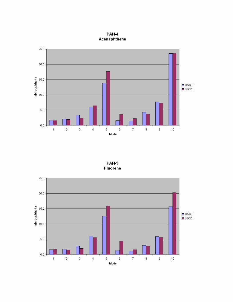
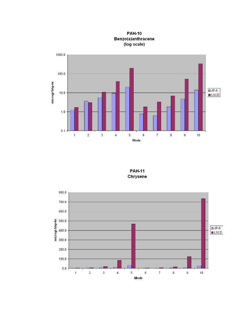
3.2.3 PAH Emissions
Particulate filters were collected during the ISO 8178 11-mode tests using low sulfur
reference diesel fuel and JP-8. Triplicate exhaust emission tests were conducted for each of
the 11 modes. Each particulate filter was extracted to remove SOF of the particulate matter
(PM). The SOF was further extracted in a Soxhlet using a solvent mixture of 30 percent
toluene/ 70 percent ethanol by volume to remove PAH compounds. At the beginning of the
extraction, a PAH surrogate spiking solution (internal standard) containing three deuterated
1.07
3 .52
789
3 .21
0 .1
0 .72
3 .23
788
3 .53
0 .155
0 .01
0 .1
1
10
100
1000
H C C O C O 2 N O x P M
g/bh
p-hr
(log
)
JP-8LS C D
18
PAHs [benzo(b)fluoranthene-d12, benzo(a)anthracene-d12, and dibenz(a,h)anthracene-d14
at 100 nanograms each] was spiked into the sample. The sample extracts were blown down
to a final volume of 100 microliters (uL). Two or three characteristic ions of each PAH were
monitored using GC/MS/SIM (selected ion monitoring) analysis. The PAHs were analyzed
in the positive ion electron impact (PI/EI) mode. A composite extract was prepared for each
of the 11 modes using equal amounts of the triplicate PAH extract. Duplicate PAH analyses
were made for the composite extracts for each fuel.
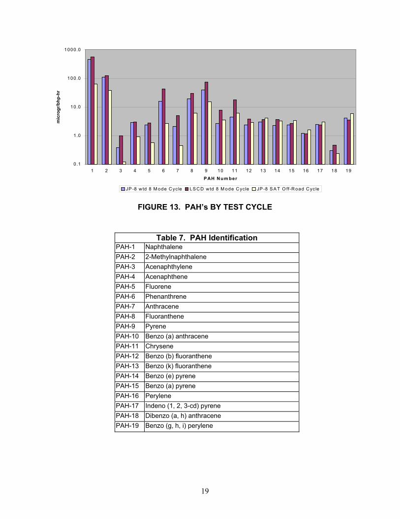
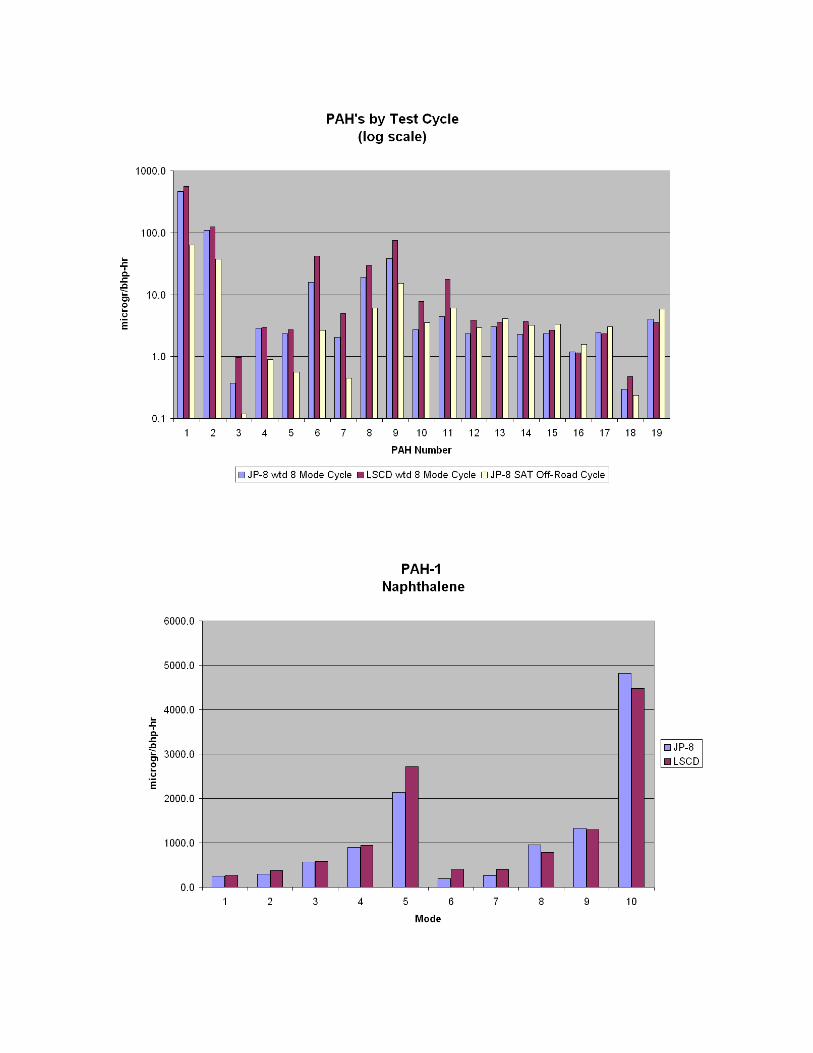
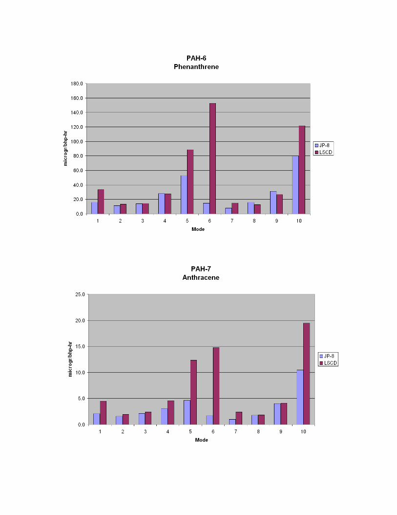
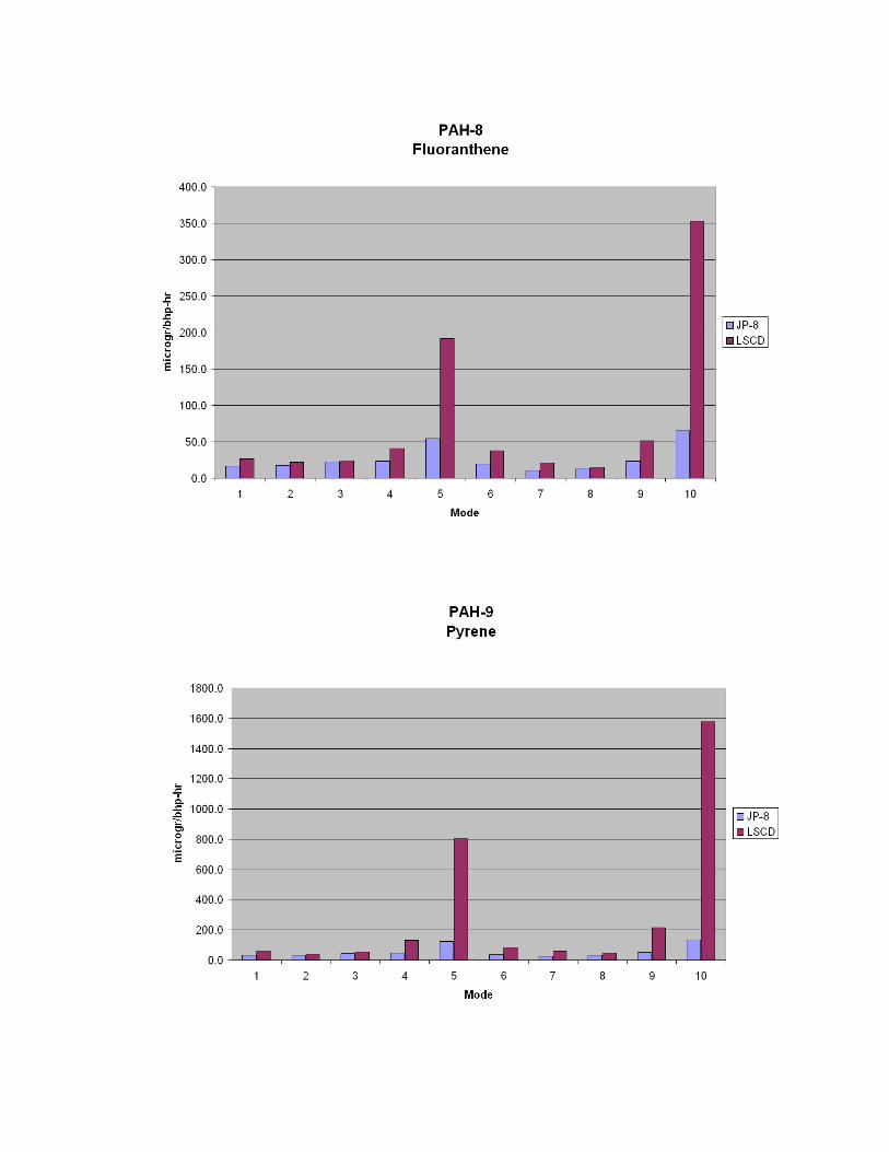
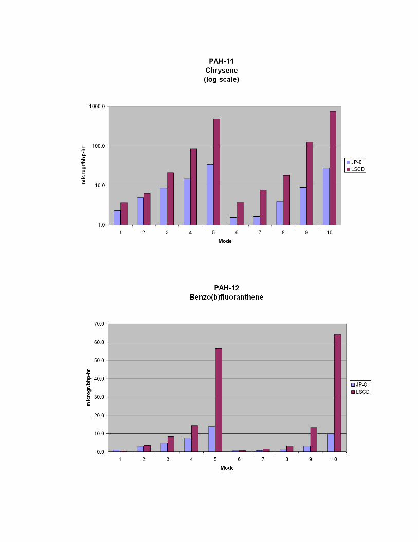
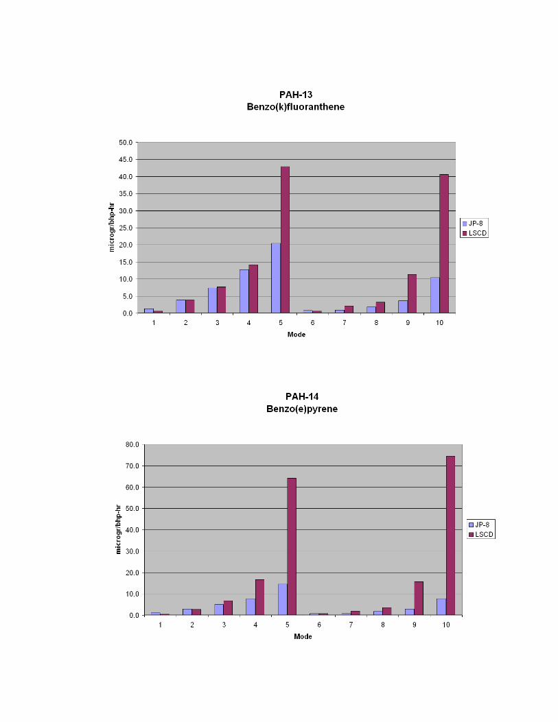
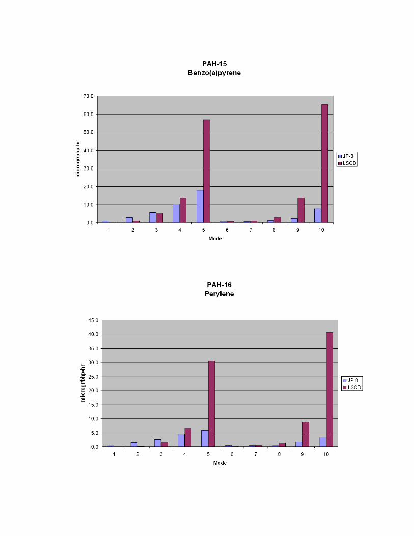
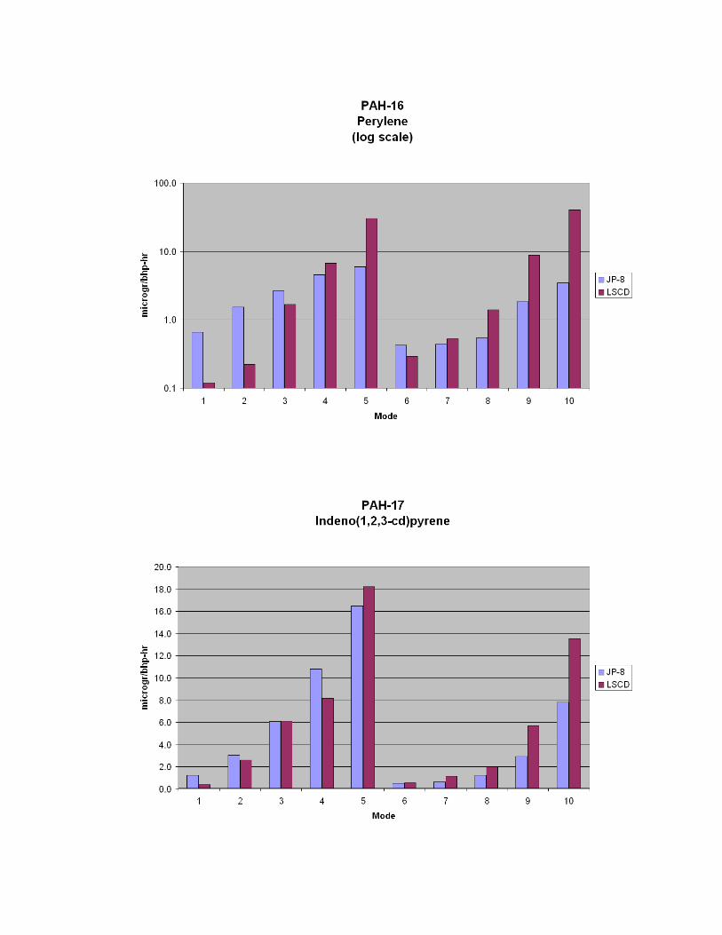
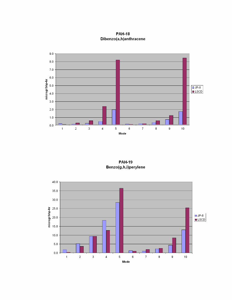
There are 19 PAH’s (response variables, shown in Table 7) for each of the 11 ISO 8178
modes. Raw data were converted into power specific emission rates for each PAH type.
Figure 13 shows a log scale plot of the PAH’s from the PM for JP-8 and LSCD. The values
are the weighted 8-mode results. Also shown are the results for JP-8 operated following the
transient nonroad (SAT) cycle. Identity of the PAH numbers are shown in Table 7. The JP-
8 fuel produced lower levels of exhaust PAH’s than the LSCD fuel, for most but not all
PAH types.
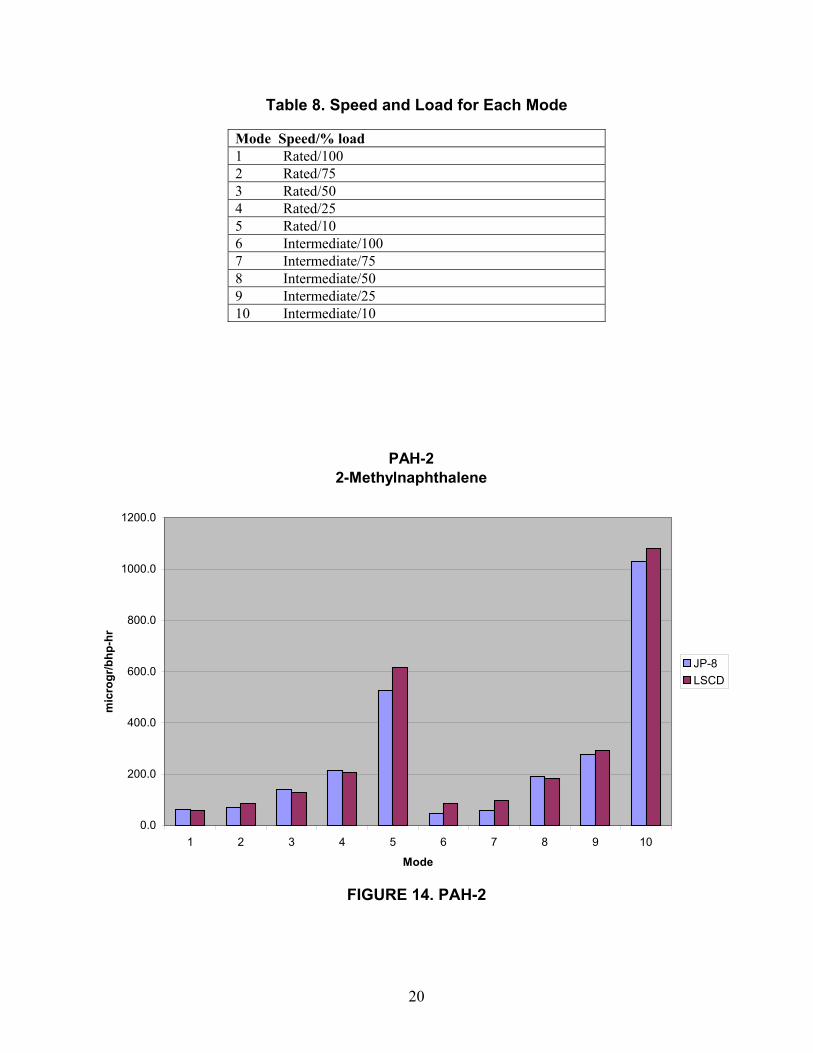
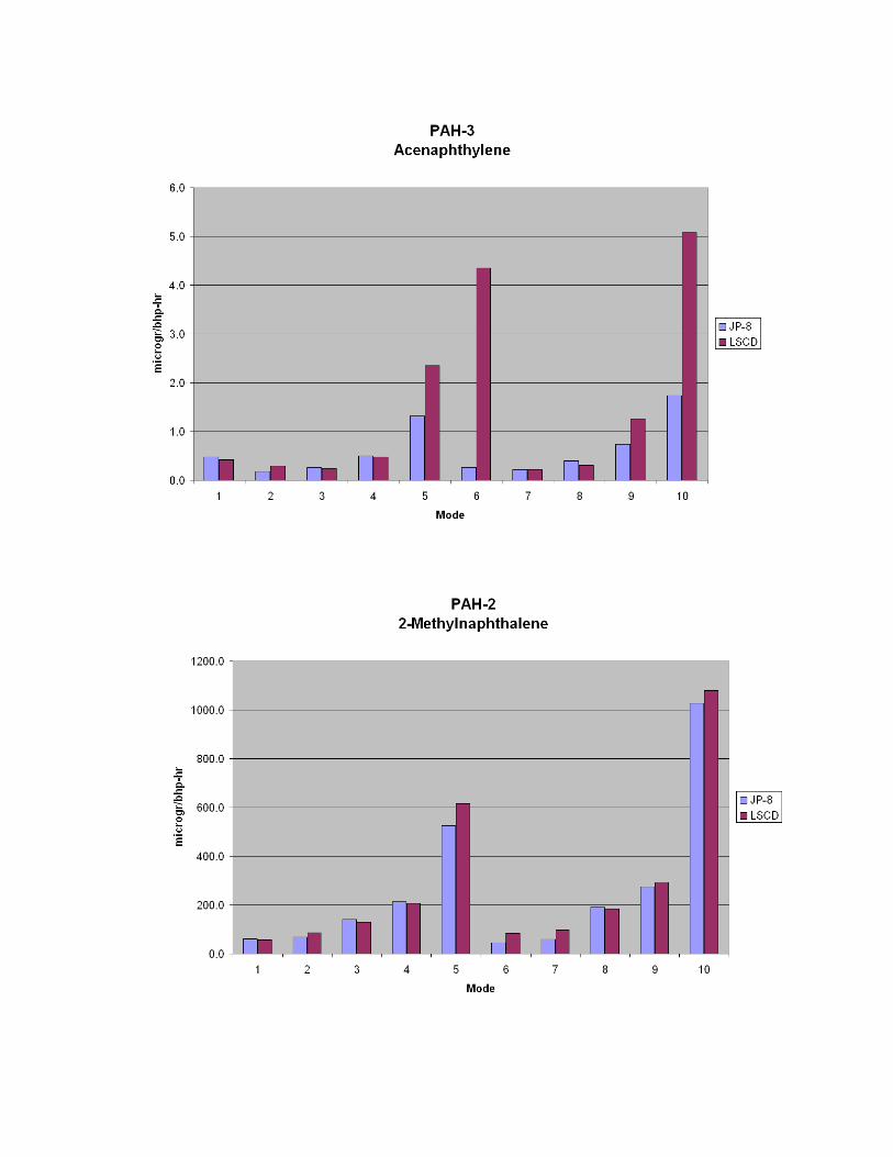
Figure 14 shows a typical plot of the brake specific amount of PAH-2 (2-
methylnaphthalene) for each operating mode (except idle). PAH-2 was extracted from the
exhaust PM of JP-8 and LSCD. Table 8 shows the mode number associated with various
speed/load combinations. Similar plots were prepared for all 19 PAH’s, and are presented in
Appendix E.
19
0.1
1.0
10.0
100.0
1000.0
1 2 3 4 5 6 7 8 9 10 11 12 13 14 15 16 17 18 19
P AH N um ber
mic
rogr
/bhp
-hr
JP -8 w td 8 M ode Cycle LS C D wtd 8 M ode Cycle JP -8 S A T O ff-R oad C ycle
FIGURE 13. PAH’s BY TEST CYCLE
Table 7. PAH IdentificationPAH-1 NaphthalenePAH-2 2-MethylnaphthalenePAH-3 AcenaphthylenePAH-4 AcenaphthenePAH-5 FluorenePAH-6 PhenanthrenePAH-7 AnthracenePAH-8 FluoranthenePAH-9 PyrenePAH-10 Benzo (a) anthracenePAH-11 ChrysenePAH-12 Benzo (b) fluoranthenePAH-13 Benzo (k) fluoranthenePAH-14 Benzo (e) pyrenePAH-15 Benzo (a) pyrenePAH-16 PerylenePAH-17 Indeno (1, 2, 3-cd) pyrenePAH-18 Dibenzo (a, h) anthracenePAH-19 Benzo (g, h, i) perylene
20
Table 8. Speed and Load for Each Mode
Mode Speed/% load1 Rated/1002 Rated/753 Rated/504 Rated/255 Rated/106 Intermediate/1007 Intermediate/758 Intermediate/509 Intermediate/2510 Intermediate/10
FIGURE 14. PAH-2
PAH-2 2-Methylnaphthalene
0.0
200.0
400.0
600.0
800.0
1000.0
1200.0
1 2 3 4 5 6 7 8 9 10
Mode
mic
rogr
/bhp
-hr
JP-8LSCD
21
4.0 SUMMARY
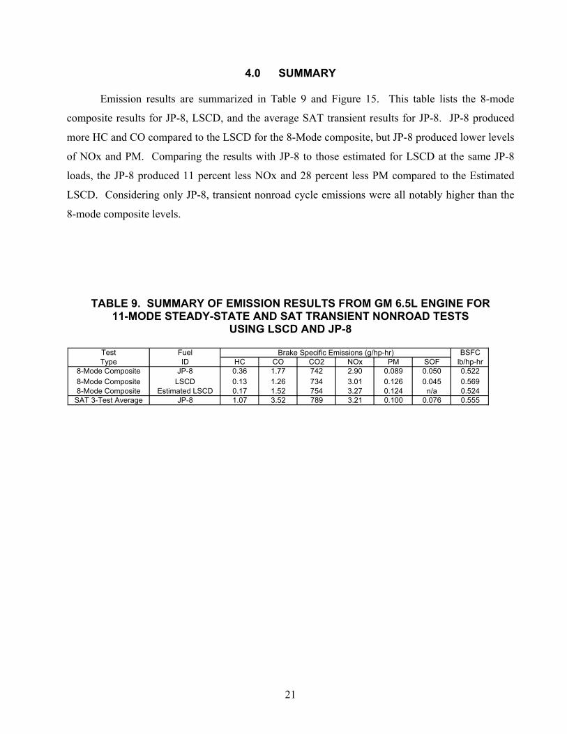
Emission results are summarized in Table 9 and Figure 15. This table lists the 8-mode
composite results for JP-8, LSCD, and the average SAT transient results for JP-8. JP-8 produced
more HC and CO compared to the LSCD for the 8-Mode composite, but JP-8 produced lower levels
of NOx and PM. Comparing the results with JP-8 to those estimated for LSCD at the same JP-8
loads, the JP-8 produced 11 percent less NOx and 28 percent less PM compared to the Estimated
LSCD. Considering only JP-8, transient nonroad cycle emissions were all notably higher than the
8-mode composite levels.
TABLE 9. SUMMARY OF EMISSION RESULTS FROM GM 6.5L ENGINE FOR11-MODE STEADY-STATE AND SAT TRANSIENT NONROAD TESTS
USING LSCD AND JP-8
Test Fuel BSFCType ID HC CO CO2 NOx PM SOF lb/hp-hr
8-Mode Composite JP-8 0.36 1.77 742 2.90 0.089 0.050 0.5228-Mode Composite LSCD 0.13 1.26 734 3.01 0.126 0.045 0.5698-Mode Composite Estimated LSCD 0.17 1.52 754 3.27 0.124 n/a 0.524
SAT 3-Test Average JP-8 1.07 3.52 789 3.21 0.100 0.076 0.555
Brake Specific Emissions (g/hp-hr)
22
FIGURE 15. WEIGHTED 8-MODE EXHAUST EMISSIONS
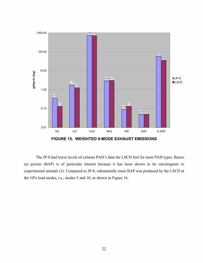
The JP-8 had lower levels of exhaust PAH’s than the LSCD fuel for most PAH types. Benzo
(a) pyrene (BAP) is of particular interest because it has been shown to be carcinogenic to
experimental animals (3). Compared to JP-8, substantially more BAP was produced by the LSCD at
the 10% load modes, i.e., modes 5 and 10, as shown in Figure 16.
0.36
1.77
742
2.90
0.09
0.05
57
0.13
1.26
734
3.01
0.13
0.05
36
0.01
0.10
1.00
10.00
100.00
1000.00
HC CO CO2 NOx PM SOF % SOF
g/b
hp-h
r (lo
g)
JP-8LSCD
23
FIGURE 16. BAP EMISSION FROM PARTICULATE MATTER
5.0 REFERENCES
1. EPA Federal Test Prodecure (FTP), as specified in the Code of Federal Regulations (CFR), Title
40, Part 89, Subpart E, titled CONTROL OF EMISSIONS FROM NEW AND IN-USE
NONROAD COMPRESSION-IGNITION ENGINES: EXHAUST EMISSION TEST
PROCEDURES.
2. EPA Federal Test Procedure, as specified in the CFR, Title 40, Part 86, Subpart N with the
exception of replacing the EPA “ENGINE DYNAMOMETER SCHEDULE FOR HEAVY-
DUTY DIESEL ENGINES” given in the CFR, Title 40, Appendix I, Subpart F(2) with the
purposed San Antonio Transient (SAT) engine dynamometer schedule.
3. International Agency for Research on Cancer (IARC)-SUMMARIES AND EVALUATIONS,
Vol. 32 (1983) p. 211.
PAH-15 Benzo(a)pyrene
0.0
10.0
20.0
30.0
40.0
50.0
60.0
70.0
1 2 3 4 5 6 7 8 9 10
Mode
mic
rogr
/bhp
-hr
JP-8LSCD
APPENDIX A
6.5L GM HEAVY-DUTY DIESEL ENGINE SPECIFICATIONS
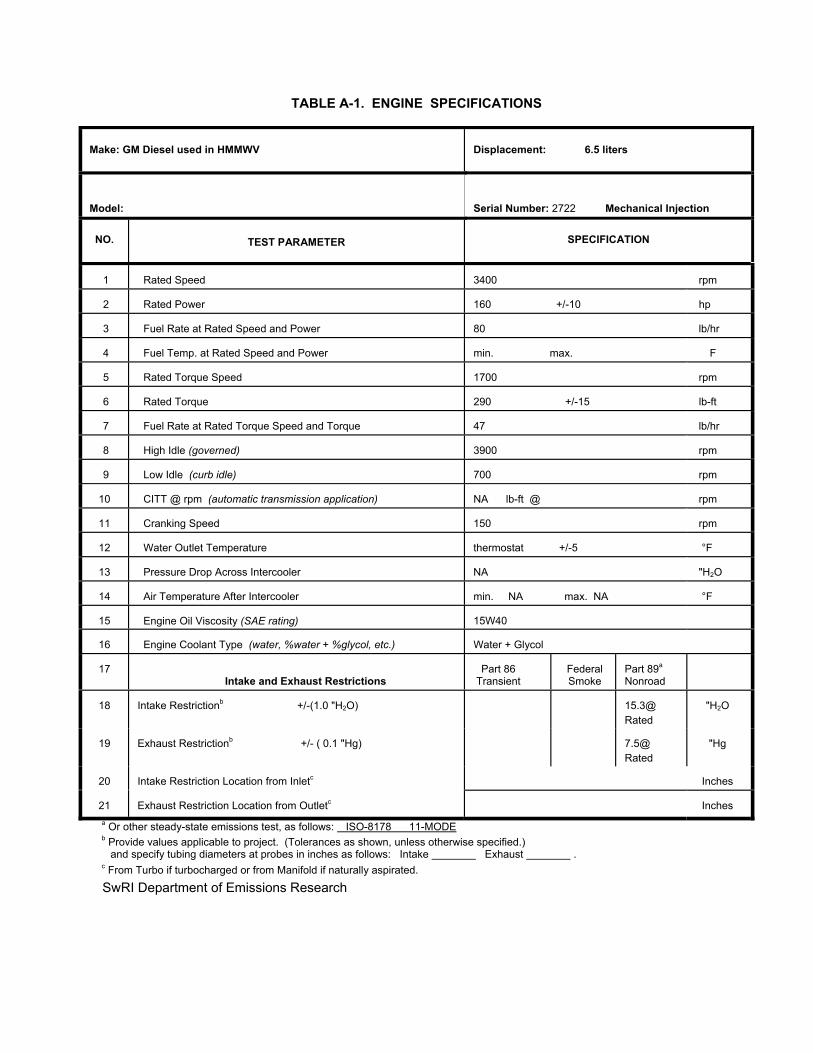
TABLE A-1. ENGINE SPECIFICATIONS
Make: GM Diesel used in HMMWV Displacement: 6.5 liters
Model: Serial Number: 2722 Mechanical Injection
NO. TEST PARAMETER SPECIFICATION
1 Rated Speed 3400 rpm
2 Rated Power 160 +/-10 hp
3 Fuel Rate at Rated Speed and Power 80 lb/hr
4 Fuel Temp. at Rated Speed and Power min. max. �F
5 Rated Torque Speed 1700 rpm
6 Rated Torque 290 +/-15 lb-ft
7 Fuel Rate at Rated Torque Speed and Torque 47 lb/hr
8 High Idle (governed) 3900 rpm
9 Low Idle (curb idle) 700 rpm
10 CITT @ rpm (automatic transmission application) NA lb-ft @ rpm
11 Cranking Speed 150 rpm
12 Water Outlet Temperature thermostat +/-5 °F
13 Pressure Drop Across Intercooler NA "H2O
14 Air Temperature After Intercooler min. NA max. NA °F
15 Engine Oil Viscosity (SAE rating) 15W40
16 Engine Coolant Type (water, %water + %glycol, etc.) Water + Glycol
17Intake and Exhaust Restrictions
Part 86Transient
FederalSmoke
Part 89a
Nonroad
18 Intake Restrictionb +/-(1.0 "H2O) 15.3@Rated
"H2O
19 Exhaust Restrictionb +/- ( 0.1 "Hg) 7.5@Rated
"Hg
20 Intake Restriction Location from Inletc Inches
21 Exhaust Restriction Location from Outletc Inches
a Or other steady-state emissions test, as follows: ISO-8178 11-MODE b Provide values applicable to project. (Tolerances as shown, unless otherwise specified.) and specify tubing diameters at probes in inches as follows: Intake Exhaust . c From Turbo if turbocharged or from Manifold if naturally aspirated.
SwRI Department of Emissions Research
APPENDIX B
BREAK-IN INSTRUCTIONS
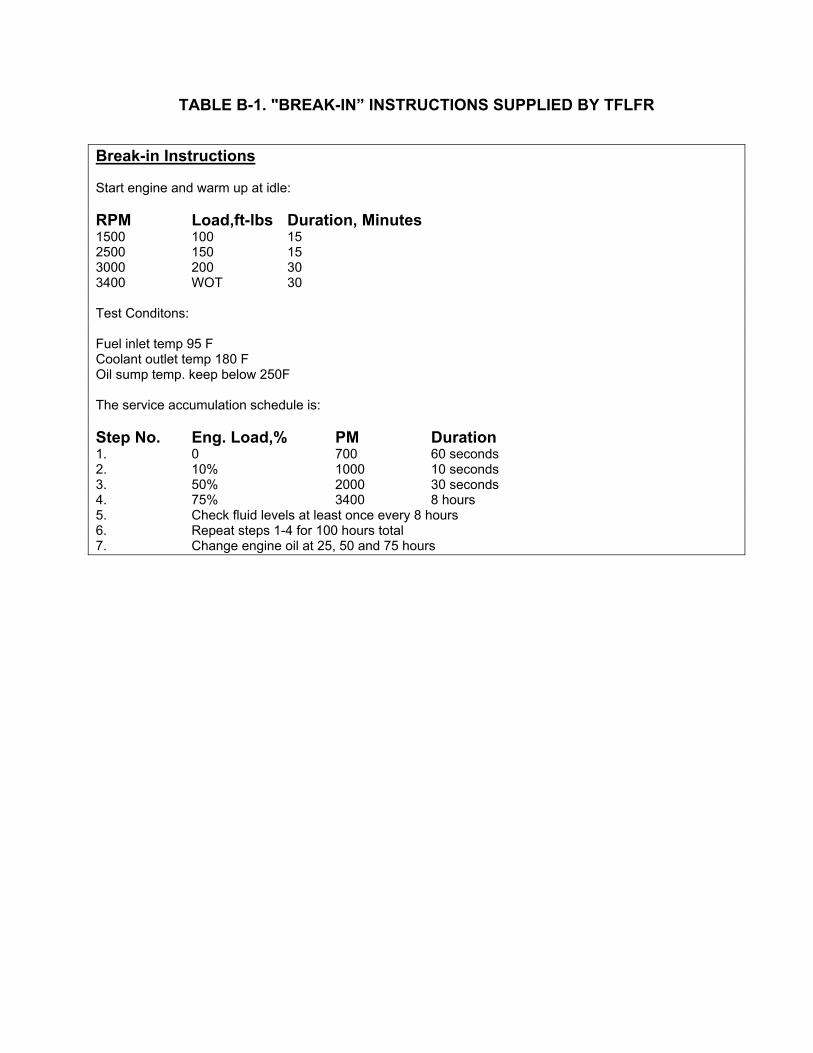
TABLE B-1. "BREAK-IN” INSTRUCTIONS SUPPLIED BY TFLFR
Break-in Instructions
Start engine and warm up at idle:
RPM Load,ft-lbs Duration, Minutes1500 100 152500 150 153000 200 303400 WOT 30
Test Conditons:
Fuel inlet temp 95 FCoolant outlet temp 180 FOil sump temp. keep below 250F
The service accumulation schedule is:
Step No. Eng. Load,% PM Duration1. 0 700 60 seconds2. 10% 1000 10 seconds3. 50% 2000 30 seconds4. 75% 3400 8 hours5. Check fluid levels at least once every 8 hours6. Repeat steps 1-4 for 100 hours total7. Change engine oil at 25, 50 and 75 hours
APPENDIX C
11-MODE STEADY-STATE EMISSION RESULTS FROM 6.5L GM HEAVY-DUTYDIESEL ENGINE USING JP-8 AND LSCD

INSERT PDF FILE HERE
APPENDIX D
SAT NONROAD TRANSIENT EMISSION RESULTS FROM 6.5L GM HEAVY-DUTYDIESEL ENGINE USING JP-8

INSERT PDF FILE HERE

APPENDIX E
BRAKE-SPECIFIC PAH’S


![[Modelik 2001 08] - M-997 HMMWV Maxi-Ambulance](https://img.pdfslide.us/doc/110x75/577cc77d1a28aba711a11bb6/modelik-2001-08-m-997-hmmwv-maxi-ambulance.jpg)