Embed Size (px)
Citation preview
A product of SEGGER Microcontroller GmbH & Co. KG
emFile
Document: UM02001Software version: 3.34
Revision: 1Date: January 7, 2015
User & Reference Guide
CPU independentFile System for
embedded applications
www.segger.com
2
Disclaimer
Specifications written in this document are believed to be accurate, but are not guar-anteed to be entirely free of error. The information in this manual is subject tochange for functional or performance improvements without notice. Please make sureyour manual is the latest edition. While the information herein is assumed to beaccurate, SEGGER Microcontroller GmbH & Co. KG (SEGGER) assumes no responsibil-ity for any errors or omissions. SEGGER makes and you receive no warranties or con-ditions, express, implied, statutory or in any communication with you. SEGGERspecifically disclaims any implied warranty of merchantability or fitness for a particu-lar purpose.
Copyright notice
You may not extract portions of this manual or modify the PDF file in any way withoutthe prior written permission of SEGGER. The software described in this document isfurnished under a license and may only be used or copied in accordance with theterms of such a license.
© 2010 - 2015 SEGGER Microcontroller GmbH & Co. KG, Hilden / Germany
Trademarks
Names mentioned in this manual may be trademarks of their respective companies.
Brand and product names are trademarks or registered trademarks of their respec-tive holders.
Contact address
SEGGER Microcontroller GmbH & Co. KG
In den Weiden 11D-40721 Hilden
Germany
Tel.+49 2103-2878-0Fax.+49 2103-2878-28E-mail: [email protected]: http://www.segger.com
UM02001 User & Reference Guide for emFile © 2010 - 2015 SEGGER Microcontroller GmbH & Co. KG
3
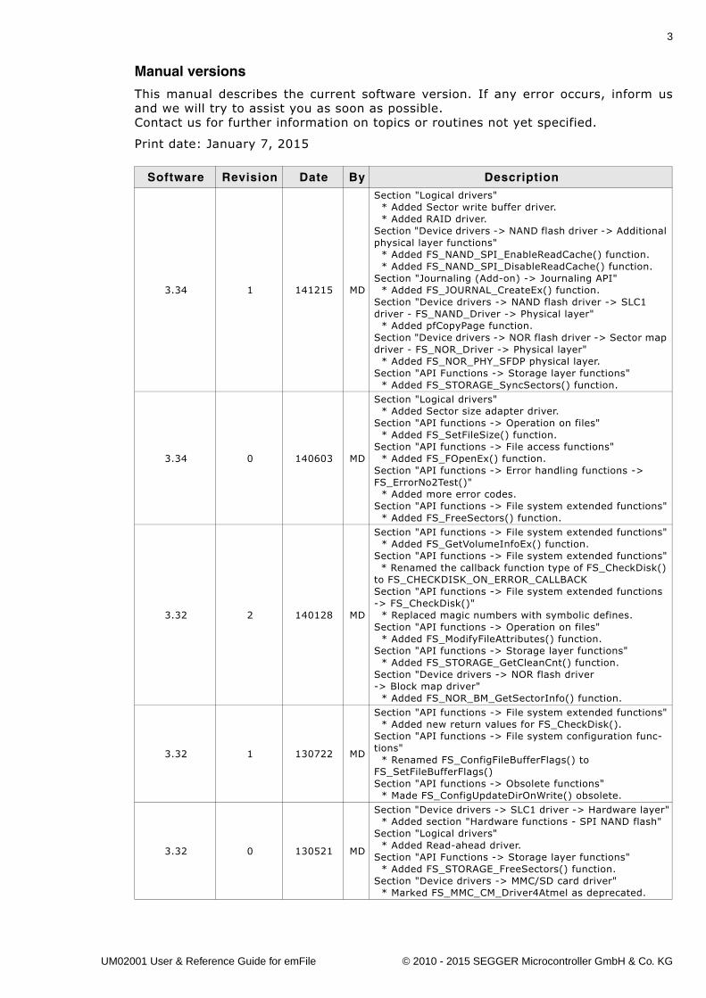
Manual versions
This manual describes the current software version. If any error occurs, inform usand we will try to assist you as soon as possible.Contact us for further information on topics or routines not yet specified.
Print date: January 7, 2015
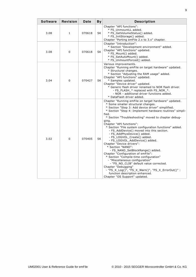
Software Revision Date By Description
3.34 1 141215 MD
Section "Logical drivers" * Added Sector write buffer driver. * Added RAID driver.Section "Device drivers -> NAND flash driver -> Additional physical layer functions" * Added FS_NAND_SPI_EnableReadCache() function. * Added FS_NAND_SPI_DisableReadCache() function.Section "Journaling (Add-on) -> Journaling API" * Added FS_JOURNAL_CreateEx() function.Section "Device drivers -> NAND flash driver -> SLC1 driver - FS_NAND_Driver -> Physical layer" * Added pfCopyPage function.Section "Device drivers -> NOR flash driver -> Sector map driver - FS_NOR_Driver -> Physical layer" * Added FS_NOR_PHY_SFDP physical layer.Section "API Functions -> Storage layer functions" * Added FS_STORAGE_SyncSectors() function.
3.34 0 140603 MD
Section "Logical drivers" * Added Sector size adapter driver.Section "API functions -> Operation on files" * Added FS_SetFileSize() function.Section "API functions -> File access functions" * Added FS_FOpenEx() function.Section "API functions -> Error handling functions -> FS_ErrorNo2Test()" * Added more error codes.Section "API functions -> File system extended functions" * Added FS_FreeSectors() function.
3.32 2 140128 MD
Section "API functions -> File system extended functions" * Added FS_GetVolumeInfoEx() function.Section "API functions -> File system extended functions" * Renamed the callback function type of FS_CheckDisk() to FS_CHECKDISK_ON_ERROR_CALLBACKSection "API functions -> File system extended functions -> FS_CheckDisk()" * Replaced magic numbers with symbolic defines.Section "API functions -> Operation on files" * Added FS_ModifyFileAttributes() function.Section "API functions -> Storage layer functions" * Added FS_STORAGE_GetCleanCnt() function.Section "Device drivers -> NOR flash driver -> Block map driver" * Added FS_NOR_BM_GetSectorInfo() function.
3.32 1 130722 MD
Section "API functions -> File system extended functions" * Added new return values for FS_CheckDisk().Section "API functions -> File system configuration func-tions" * Renamed FS_ConfigFileBufferFlags() to FS_SetFileBufferFlags()Section "API functions -> Obsolete functions" * Made FS_ConfigUpdateDirOnWrite() obsolete.
3.32 0 130521 MD
Section "Device drivers -> SLC1 driver -> Hardware layer" * Added section "Hardware functions - SPI NAND flash"Section "Logical drivers" * Added Read-ahead driver.Section "API Functions -> Storage layer functions" * Added FS_STORAGE_FreeSectors() function.Section "Device drivers -> MMC/SD card driver" * Marked FS_MMC_CM_Driver4Atmel as deprecated.
UM02001 User & Reference Guide for emFile © 2010 - 2015 SEGGER Microcontroller GmbH & Co. KG
4
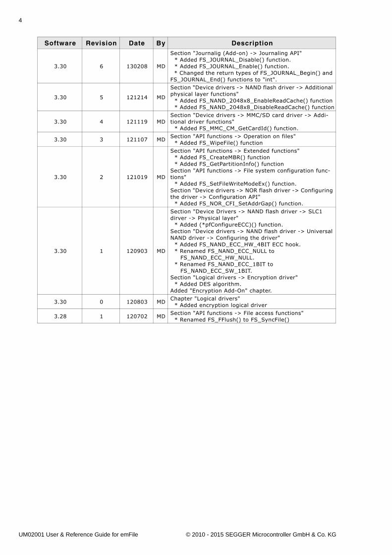
3.30 6 130208 MD
Section "Journalig (Add-on) -> Journaling API" * Added FS_JOURNAL_Disable() function. * Added FS_JOURNAL_Enable() function. * Changed the return types of FS_JOURNAL_Begin() and FS_JOURNAL_End() functions to "int".
3.30 5 121214 MD
Section "Device drivers -> NAND flash driver -> Additional physical layer functions" * Added FS_NAND_2048x8_EnableReadCache() function * Added FS_NAND_2048x8_DisableReadCache() function
3.30 4 121119 MDSection "Device drivers -> MMC/SD card driver -> Addi-tional driver functions" * Added FS_MMC_CM_GetCardId() function.
3.30 3 121107 MDSection "API functions -> Operation on files" * Added FS_WipeFile() function
3.30 2 121019 MD
Section "API functions -> Extended functions" * Added FS_CreateMBR() function * Added FS_GetPartitionInfo() functionSection "API functions -> File system configuration func-tions" * Added FS_SetFileWriteModeEx() function.Section "Device drivers -> NOR flash driver -> Configuring the driver -> Configuration API" * Added FS_NOR_CFI_SetAddrGap() function.
3.30 1 120903 MD
Section "Device Drivers -> NAND flash driver -> SLC1 dirver -> Physical layer" * Added (*pfConfigureECC)() function.Section "Device drivers -> NAND flash driver -> Universal NAND driver -> Configuring the driver" * Added FS_NAND_ECC_HW_4BIT ECC hook. * Renamed FS_NAND_ECC_NULL to FS_NAND_ECC_HW_NULL. * Renamed FS_NAND_ECC_1BIT to FS_NAND_ECC_SW_1BIT.Section "Logical drivers -> Encryption driver" * Added DES algorithm.Added "Encryption Add-On" chapter.
3.30 0 120803 MDChapter "Logical drivers" * Added encryption logical driver
3.28 1 120702 MDSection "API functions -> File access functions" * Renamed FS_FFlush() to FS_SyncFile()
Software Revision Date By Description
UM02001 User & Reference Guide for emFile © 2010 - 2015 SEGGER Microcontroller GmbH & Co. KG
5
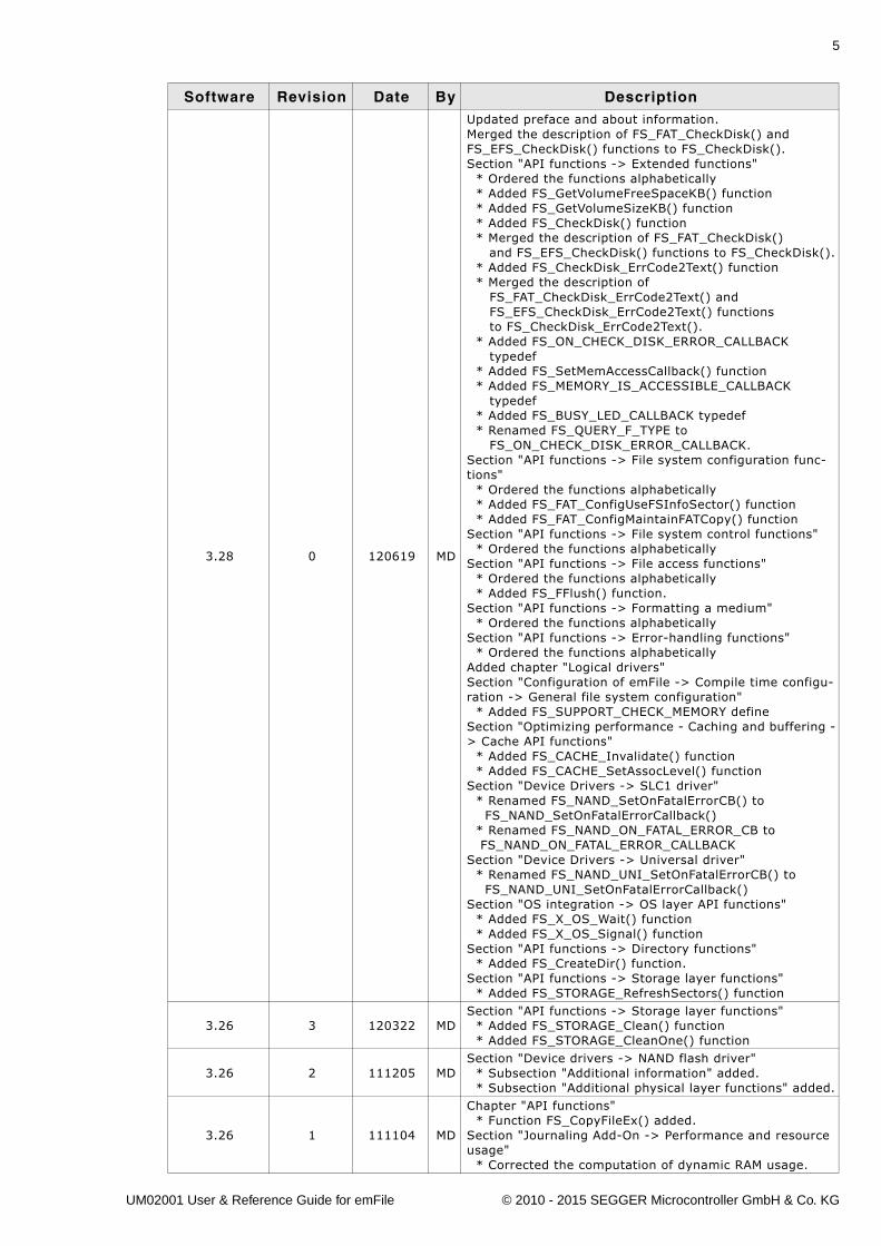
3.28 0 120619 MD
Updated preface and about information.Merged the description of FS_FAT_CheckDisk() and FS_EFS_CheckDisk() functions to FS_CheckDisk().Section "API functions -> Extended functions" * Ordered the functions alphabetically * Added FS_GetVolumeFreeSpaceKB() function * Added FS_GetVolumeSizeKB() function * Added FS_CheckDisk() function * Merged the description of FS_FAT_CheckDisk() and FS_EFS_CheckDisk() functions to FS_CheckDisk(). * Added FS_CheckDisk_ErrCode2Text() function * Merged the description of FS_FAT_CheckDisk_ErrCode2Text() and FS_EFS_CheckDisk_ErrCode2Text() functions to FS_CheckDisk_ErrCode2Text(). * Added FS_ON_CHECK_DISK_ERROR_CALLBACK typedef * Added FS_SetMemAccessCallback() function * Added FS_MEMORY_IS_ACCESSIBLE_CALLBACK typedef * Added FS_BUSY_LED_CALLBACK typedef * Renamed FS_QUERY_F_TYPE to FS_ON_CHECK_DISK_ERROR_CALLBACK.Section "API functions -> File system configuration func-tions" * Ordered the functions alphabetically * Added FS_FAT_ConfigUseFSInfoSector() function * Added FS_FAT_ConfigMaintainFATCopy() functionSection "API functions -> File system control functions" * Ordered the functions alphabeticallySection "API functions -> File access functions" * Ordered the functions alphabetically * Added FS_FFlush() function.Section "API functions -> Formatting a medium" * Ordered the functions alphabeticallySection "API functions -> Error-handling functions" * Ordered the functions alphabeticallyAdded chapter "Logical drivers"Section "Configuration of emFile -> Compile time configu-ration -> General file system configuration" * Added FS_SUPPORT_CHECK_MEMORY defineSection "Optimizing performance - Caching and buffering -> Cache API functions" * Added FS_CACHE_Invalidate() function * Added FS_CACHE_SetAssocLevel() functionSection "Device Drivers -> SLC1 driver" * Renamed FS_NAND_SetOnFatalErrorCB() to FS_NAND_SetOnFatalErrorCallback() * Renamed FS_NAND_ON_FATAL_ERROR_CB to FS_NAND_ON_FATAL_ERROR_CALLBACKSection "Device Drivers -> Universal driver" * Renamed FS_NAND_UNI_SetOnFatalErrorCB() to FS_NAND_UNI_SetOnFatalErrorCallback()Section "OS integration -> OS layer API functions" * Added FS_X_OS_Wait() function * Added FS_X_OS_Signal() functionSection "API functions -> Directory functions" * Added FS_CreateDir() function.Section "API functions -> Storage layer functions" * Added FS_STORAGE_RefreshSectors() function
3.26 3 120322 MDSection "API functions -> Storage layer functions" * Added FS_STORAGE_Clean() function * Added FS_STORAGE_CleanOne() function
3.26 2 111205 MDSection "Device drivers -> NAND flash driver" * Subsection "Additional information" added. * Subsection "Additional physical layer functions" added.
3.26 1 111104 MD
Chapter "API functions" * Function FS_CopyFileEx() added.Section "Journaling Add-On -> Performance and resource usage" * Corrected the computation of dynamic RAM usage.
Software Revision Date By Description
UM02001 User & Reference Guide for emFile © 2010 - 2015 SEGGER Microcontroller GmbH & Co. KG
6
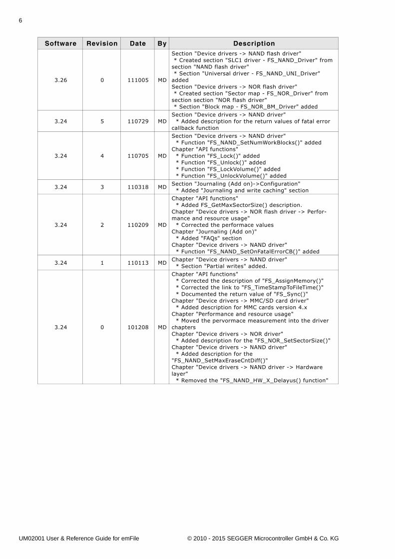
3.26 0 111005 MD
Section "Device drivers -> NAND flash driver" * Created section "SLC1 driver - FS_NAND_Driver" from section "NAND flash driver" * Section "Universal driver - FS_NAND_UNI_Driver" addedSection "Device drivers -> NOR flash driver" * Created section "Sector map - FS_NOR_Driver" from section section "NOR flash driver" * Section "Block map - FS_NOR_BM_Driver" added
3.24 5 110729 MDSection "Device drivers -> NAND driver" * Added description for the return values of fatal error callback function
3.24 4 110705 MD
Section "Device drivers -> NAND driver" * Function "FS_NAND_SetNumWorkBlocks()" addedChapter "API functions" * Function "FS_Lock()" added * Function "FS_Unlock()" added * Function "FS_LockVolume()" added * Function "FS_UnlockVolume()" added
3.24 3 110318 MDSection "Journaling (Add on)->Configuration" * Added "Journaling and write caching" section
3.24 2 110209 MD
Chapter "API functions" * Added FS_GetMaxSectorSize() description.Chapter "Device drivers -> NOR flash driver -> Perfor-mance and resource usage" * Corrected the performace valuesChapter "Journaling (Add on)" * Added "FAQs" sectionChapter "Device drivers -> NAND driver" * Function "FS_NAND_SetOnFatalErrorCB()" added
3.24 1 110113 MDChapter "Device drivers -> NAND driver" * Section "Partial writes" added.
3.24 0 101208 MD
Chapter "API functions" * Corrected the description of "FS_AssignMemory()" * Corrected the link to "FS_TimeStampToFileTime()" * Documented the return value of "FS_Sync()"Chapter "Device drivers -> MMC/SD card driver" * Added description for MMC cards version 4.xChapter "Performance and resource usage" * Moved the pervormace measurement into the driver chaptersChapter "Device drivers -> NOR driver" * Added description for the "FS_NOR_SetSectorSize()"Chapter "Device drivers -> NAND driver" * Added description for the "FS_NAND_SetMaxEraseCntDiff()"Chapter "Device drivers -> NAND driver -> Hardware layer" * Removed the "FS_NAND_HW_X_Delayus() function"
Software Revision Date By Description
UM02001 User & Reference Guide for emFile © 2010 - 2015 SEGGER Microcontroller GmbH & Co. KG
7
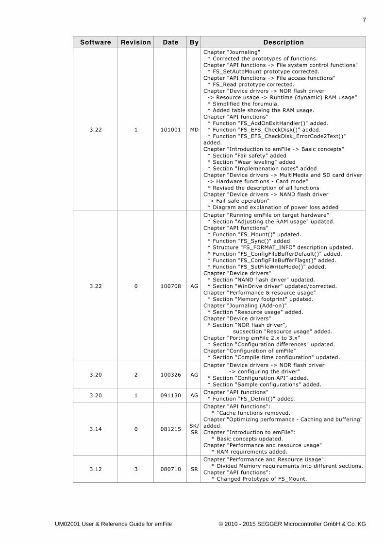
3.22 1 101001 MD
Chapter "Journaling" * Corrected the prototypes of functions.Chapter "API functions -> File system control functions" * FS_SetAutoMount prototype corrected.Chapter "API functions -> File access functions" * FS_Read prototype corrected.Chapter "Device drivers -> NOR flash driver -> Resource usage -> Runtime (dynamic) RAM usage" * Simplified the forumula. * Added table showing the RAM usage.Chapter "API functions" * Function "FS_AddOnExitHandler()" added. * Function "FS_EFS_CheckDisk()" added. * Function "FS_EFS_CheckDisk_ErrorCode2Text()" added.Chapter "Introduction to emFile -> Basic concepts" * Section "Fail safety" added * Section "Wear leveling" added * Section "Implemenation notes" addedChapter "Device drivers -> MultiMedia and SD card driver -> Hardware functions - Card mode" * Revised the description of all functionsChapter "Device drivers -> NAND flash driver -> Fail-safe operation" * Diagram and explanation of power loss added
3.22 0 100708 AG
Chapter "Running emFile on target hardware" * Section "Adjusting the RAM usage" updated.Chapter "API functions" * Function "FS_Mount()" updated. * Function "FS_Sync()" added. * Structure "FS_FORMAT_INFO" description updated. * Function "FS_ConfigFileBufferDefault()" added. * Function "FS_ConfigFileBufferFlags()" added. * Function "FS_SetFileWriteMode()" added.Chapter "Device drivers" * Section "NAND flash driver" updated. * Section "WinDrive driver" updated/corrected.Chapter "Performance & resource usage" * Section "Memory footprint" updated.Chapter "Journaling (Add-on)" * Section "Resource usage" added.Chapter "Device drivers" * Section "NOR flash driver", subsection "Resource usage" added.Chapter "Porting emFile 2.x to 3.x" * Section "Configuration differences" updated.Chapter "Configuration of emFile" * Section "Compile time configuration" updated.
3.20 2 100326 AG
Chapter "Device drivers -> NOR flash driver -> configuring the driver" * Section "Configuration API" added. * Section "Sample configurations" added.
3.20 1 091130 AGChapter "API functions" * Function "FS_DeInit()" added.
3.14 0 081215SK/SR
Chapter "API functions": * "Cache functions removed.Chapter "Optimizing performance - Caching and buffering" added.Chapter "Introduction to emFile": * Basic concepts updated.Chapter "Performance and resource usage" * RAM requirements added.
3.12 3 080710 SR
Chapter "Performance and Resource Usage": * Divided Memory requirements into different sections.Chapter "API functions": * Changed Prototype of FS_Mount.
Software Revision Date By Description
UM02001 User & Reference Guide for emFile © 2010 - 2015 SEGGER Microcontroller GmbH & Co. KG
8
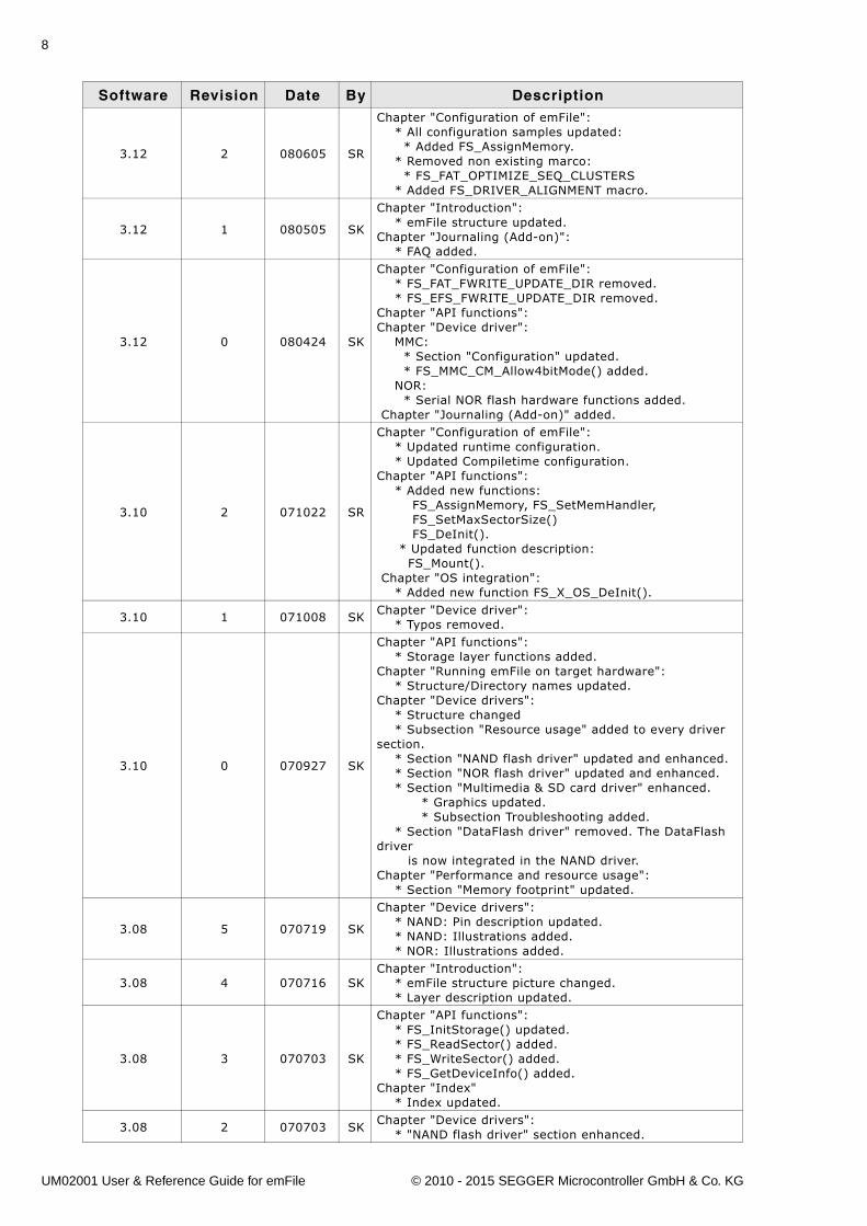
3.12 2 080605 SR
Chapter "Configuration of emFile": * All configuration samples updated: * Added FS_AssignMemory. * Removed non existing marco: * FS_FAT_OPTIMIZE_SEQ_CLUSTERS * Added FS_DRIVER_ALIGNMENT macro.
3.12 1 080505 SK
Chapter "Introduction": * emFile structure updated.Chapter "Journaling (Add-on)": * FAQ added.
3.12 0 080424 SK
Chapter "Configuration of emFile": * FS_FAT_FWRITE_UPDATE_DIR removed. * FS_EFS_FWRITE_UPDATE_DIR removed.Chapter "API functions":Chapter "Device driver": MMC: * Section "Configuration" updated. * FS_MMC_CM_Allow4bitMode() added. NOR: * Serial NOR flash hardware functions added. Chapter "Journaling (Add-on)" added.
3.10 2 071022 SR
Chapter "Configuration of emFile": * Updated runtime configuration. * Updated Compiletime configuration.Chapter "API functions": * Added new functions: FS_AssignMemory, FS_SetMemHandler, FS_SetMaxSectorSize() FS_DeInit(). * Updated function description: FS_Mount(). Chapter "OS integration": * Added new function FS_X_OS_DeInit().
3.10 1 071008 SKChapter "Device driver": * Typos removed.
3.10 0 070927 SK
Chapter "API functions": * Storage layer functions added.Chapter "Running emFile on target hardware": * Structure/Directory names updated.Chapter "Device drivers": * Structure changed * Subsection "Resource usage" added to every driver section. * Section "NAND flash driver" updated and enhanced. * Section "NOR flash driver" updated and enhanced. * Section "Multimedia & SD card driver" enhanced. * Graphics updated. * Subsection Troubleshooting added. * Section "DataFlash driver" removed. The DataFlash driver is now integrated in the NAND driver.Chapter "Performance and resource usage": * Section "Memory footprint" updated.
3.08 5 070719 SK
Chapter "Device drivers": * NAND: Pin description updated. * NAND: Illustrations added. * NOR: Illustrations added.
3.08 4 070716 SKChapter "Introduction": * emFile structure picture changed. * Layer description updated.
3.08 3 070703 SK
Chapter "API functions": * FS_InitStorage() updated. * FS_ReadSector() added. * FS_WriteSector() added. * FS_GetDeviceInfo() added.Chapter "Index" * Index updated.
3.08 2 070703 SKChapter "Device drivers": * "NAND flash driver" section enhanced.
Software Revision Date By Description
UM02001 User & Reference Guide for emFile © 2010 - 2015 SEGGER Microcontroller GmbH & Co. KG
9
3.08 1 070618 SK
Chapter "API functions": * FS_UnmountLL added. * FS_GetVolumeStatus() added. * FS_InitStorage() added.Chapter "Porting emFile 2.x to 3.x" chapter.
3.08 0 070618 SK
Chapter "Introduction": * Section "Development environment" added.Chapter "API functions" updated. * FS_Mount() added. * FS_SetAutoMount() added. * FS_UnmountForced() added.
3.04 0 070427 SK
Various improvements.Chapter "Running emFile on target hardware" updated. * Structural changes. * Section "Adjusting the RAM usage" added.Chapter "API functions" updated. * Samples updated.Chapter "Device driver" updated. * Generic flash driver renamed to NOR flash driver. - FS_FLASH_* replaced with FS_NOR_*. - NOR - additional driver functions added. * DataFlash driver added.
3.02 0 070405 SK
Chapter "Running emFile on target hardware" updated. * Some smaller structural changes. * Section "Step 3: Add device driver" simplified. * Section "Step 4: Implement hardware routines" simpli-fied. * Section "Troubleshooting" moved to chapter debug-ging.Chapter "API functions": * Section "File system configuration functions" added. - FS_AddDevice() moved into this section. - FS_AddPhysDevice() added. - FS_LOGVOL_Create() added. - FS_LOGVOL_AddDevice() added.Chapter "Device drivers": * Section "NAND": - FS_NAND_SetBlockRange() added.Chapter "Configuration of emFile": * Section "Compile-time configuration" - "Miscellaneous configuration" - "FS_NO_CLIB" default value corrected.Chapter "Debugging" - "FS_X_Log()", "FS_X_Warn()", "FS_X_ErrorOut()" : function description enhanced.Chapter "OS Support" updated.
Software Revision Date By Description
UM02001 User & Reference Guide for emFile © 2010 - 2015 SEGGER Microcontroller GmbH & Co. KG

10
UM02001 User & Reference Guide for emFile © 2010 - 2015 SEGGER Microcontroller GmbH & Co. KG
11
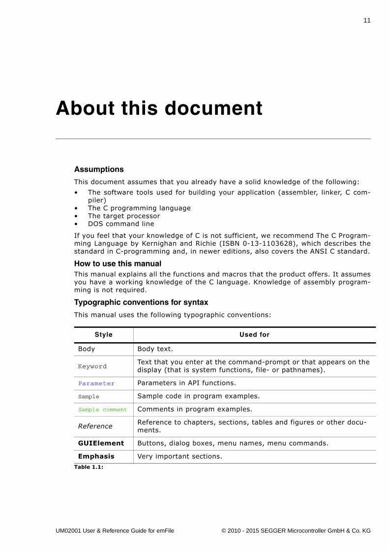
About this document
Assumptions
This document assumes that you already have a solid knowledge of the following:
� The software tools used for building your application (assembler, linker, C com-piler)
� The C programming language� The target processor� DOS command line
If you feel that your knowledge of C is not sufficient, we recommend The C Program-ming Language by Kernighan and Richie (ISBN 0-13-1103628), which describes thestandard in C-programming and, in newer editions, also covers the ANSI C standard.
How to use this manualThis manual explains all the functions and macros that the product offers. It assumesyou have a working knowledge of the C language. Knowledge of assembly program-ming is not required.
Typographic conventions for syntax
This manual uses the following typographic conventions:
Style Used for
Body Body text.
KeywordText that you enter at the command-prompt or that appears on the display (that is system functions, file- or pathnames).
Parameter Parameters in API functions.
Sample Sample code in program examples.
Sample comment Comments in program examples.
Reference Reference to chapters, sections, tables and figures or other docu-ments.
GUIElement Buttons, dialog boxes, menu names, menu commands.
Emphasis Very important sections.
Table 1.1:
UM02001 User & Reference Guide for emFile © 2010 - 2015 SEGGER Microcontroller GmbH & Co. KG
12
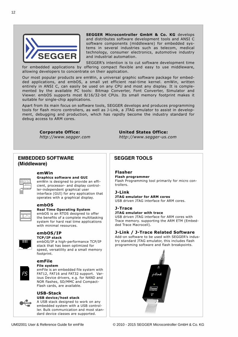
EMBEDDED SOFTWARE(Middleware)
emWinGraphics software and GUIemWin is designed to provide an effi-cient, processor- and display control-ler-independent graphical user interface (GUI) for any application that operates with a graphical display.
embOSReal Time Operating SystemembOS is an RTOS designed to offer the benefits of a complete multitasking system for hard real time applications with minimal resources.
embOS/IPTCP/IP stackembOS/IP a high-performance TCP/IP stack that has been optimized for speed, versatility and a small memory footprint.
emFileFile systememFile is an embedded file system with FAT12, FAT16 and FAT32 support. Var-ious Device drivers, e.g. for NAND and NOR flashes, SD/MMC and Compact-Flash cards, are available.
USB-StackUSB device/host stackA USB stack designed to work on any embedded system with a USB control-ler. Bulk communication and most stan-dard device classes are supported.
SEGGER TOOLS
Flasher Flash programmerFlash Programming tool primarily for micro con-trollers.
J-LinkJTAG emulator for ARM coresUSB driven JTAG interface for ARM cores.
J-TraceJTAG emulator with traceUSB driven JTAG interface for ARM cores with Trace memory. supporting the ARM ETM (Embed-ded Trace Macrocell).
J-Link / J-Trace Related SoftwareAdd-on software to be used with SEGGER�s indus-try standard JTAG emulator, this includes flash programming software and flash breakpoints.
SEGGER Microcontroller GmbH & Co. KG developsand distributes software development tools and ANSI Csoftware components (middleware) for embedded sys-tems in several industries such as telecom, medicaltechnology, consumer electronics, automotive industryand industrial automation.
SEGGER�s intention is to cut software development timefor embedded applications by offering compact flexible and easy to use middleware,allowing developers to concentrate on their application.
Our most popular products are emWin, a universal graphic software package for embed-ded applications, and embOS, a small yet efficient real-time kernel. emWin, writtenentirely in ANSI C, can easily be used on any CPU and most any display. It is comple-mented by the available PC tools: Bitmap Converter, Font Converter, Simulator andViewer. embOS supports most 8/16/32-bit CPUs. Its small memory footprint makes itsuitable for single-chip applications.
Apart from its main focus on software tools, SEGGER develops and produces programmingtools for flash micro controllers, as well as J-Link, a JTAG emulator to assist in develop-ment, debugging and production, which has rapidly become the industry standard fordebug access to ARM cores.
Corporate Office:http://www.segger.com
United States Office:http://www.segger-us.com
UM02001 User & Reference Guide for emFile © 2010 - 2015 SEGGER Microcontroller GmbH & Co. KG
13
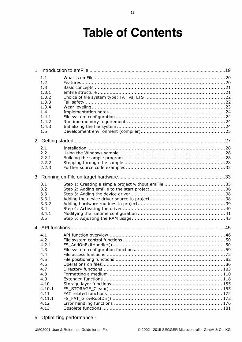
Table of Contents
1 Introduction to emFile ....................................................................................................19
1.1 What is emFile ........................................................................................201.2 Features.................................................................................................201.3 Basic concepts ........................................................................................211.3.1 emFile structure ......................................................................................211.3.2 Choice of file system type: FAT vs. EFS ......................................................221.3.3 Fail safety...............................................................................................221.3.4 Wear leveling ..........................................................................................231.4 Implementation notes ..............................................................................241.4.1 File system configuration ..........................................................................241.4.2 Runtime memory requirements .................................................................241.4.3 Initializing the file system .........................................................................241.5 Development environment (compiler).........................................................25
2 Getting started ...............................................................................................................27
2.1 Installation .............................................................................................282.2 Using the Windows sample........................................................................282.2.1 Building the sample program.....................................................................282.2.2 Stepping through the sample ....................................................................282.2.3 Further source code examples ...................................................................32
3 Running emFile on target hardware...............................................................................33
3.1 Step 1: Creating a simple project without emFile .........................................353.2 Step 2: Adding emFile to the start project...................................................363.3 Step 3: Adding the device driver................................................................383.3.1 Adding the device driver source to project...................................................383.3.2 Adding hardware routines to project...........................................................393.4 Step 4: Activating the driver .....................................................................403.4.1 Modifying the runtime configuration ...........................................................413.5 Step 5: Adjusting the RAM usage...............................................................43
4 API functions..................................................................................................................45
4.1 API function overview...............................................................................464.2 File system control functions .....................................................................504.2.1 FS_AddOnExitHandler()............................................................................504.3 File system configuration functions.............................................................594.4 File access functions ................................................................................724.5 File positioning functions ..........................................................................824.6 Operations on files...................................................................................864.7 Directory functions ................................................................................ 1034.8 Formatting a medium............................................................................. 1104.9 Extended functions ................................................................................ 1184.10 Storage layer functions........................................................................... 1554.10.1 FS_STORAGE_Clean() ............................................................................ 1554.11 FAT related functions ............................................................................. 1724.11.1 FS_FAT_GrowRootDir() .......................................................................... 1724.12 Error handling functions ......................................................................... 1764.13 Obsolete functions ................................................................................. 181
5 Optimizing performance -
UM02001 User & Reference Guide for emFile © 2002 - 2015 SEGGER Microcontroller GmbH & Co. KG
14
Caching and buffering.......................................................................................................197
5.1 Introduction ..........................................................................................1985.2 Types of caches .....................................................................................1995.3 Cache API functions................................................................................2005.4 Example applications ..............................................................................2105.4.1 Example application: FS_50Files.c ............................................................210
6 Device drivers ..............................................................................................................213
6.1 General information................................................................................2146.1.1 Default device driver names ....................................................................2146.1.2 Unit number ..........................................................................................2146.1.3 Hardware layer ......................................................................................2146.2 RAM disk driver......................................................................................2176.2.1 Supported hardware ...............................................................................2176.2.2 Theory of operation ................................................................................2176.2.3 Fail-safe operation..................................................................................2176.2.4 Wear leveling ........................................................................................2176.2.5 Configuring the driver .............................................................................2186.2.6 Hardware functions ................................................................................2206.2.7 Additional information.............................................................................2206.2.8 Performance and resource usage..............................................................2206.3 NAND flash driver...................................................................................2216.3.1 SLC1 driver - FS_NAND_Driver ................................................................2226.3.2 Universal driver - FS_NAND_UNI_Driver....................................................2906.3.3 Additional Information ............................................................................3086.3.4 Additional physical layer functions ............................................................3086.4 NOR flash driver.....................................................................................3156.4.1 Sector map driver - FS_NOR_Driver..........................................................3156.4.2 Block map - FS_NOR_BM_Driver ..............................................................3576.5 MMC/SD card driver ...............................................................................3736.5.1 Supported hardware ...............................................................................3736.5.2 Theory of operation ................................................................................3796.5.3 Fail-safe operation..................................................................................3796.5.4 Wear leveling ........................................................................................3796.5.5 Configuration.........................................................................................3796.5.6 Hardware functions - SPI mode................................................................3836.5.7 Hardware functions - Card mode .............................................................3926.5.8 Hardware functions - Card mode for ATMEL devices ....................................4076.5.9 Additional information.............................................................................4176.5.10 Additional driver functions .......................................................................4176.5.11 Performance and resource usage..............................................................4206.5.12 Troubleshooting .....................................................................................4206.6 CompactFlash card and IDE driver ............................................................4256.6.1 Supported Hardware...............................................................................4256.6.2 Theory of operation ................................................................................4306.6.3 Fail-safe operation..................................................................................4356.6.4 Wear-leveling ........................................................................................4366.6.5 Configuring the driver .............................................................................4366.6.6 Hardware functions ................................................................................4376.6.7 Additional information.............................................................................4456.6.8 Performance and resource usage..............................................................4456.7 WinDrive driver......................................................................................4466.7.1 Supported hardware ...............................................................................4466.7.2 Theory of operation ................................................................................4466.7.3 Fail-safe operation..................................................................................4466.7.4 Wear leveling ........................................................................................4466.7.5 Configuring the driver .............................................................................4466.7.6 Hardware functions ................................................................................4476.7.7 Additional information.............................................................................4476.8 Writing your own driver ..........................................................................448
UM02001 User & Reference Guide for emFile © 2002 - 2015 SEGGER Microcontroller GmbH & Co. KG
15
6.8.1 Device driver functions ........................................................................... 4486.8.2 Integrating a new driver ......................................................................... 450
7 Logical drivers..............................................................................................................451
7.1 General information ............................................................................... 4527.1.1 Default logical driver names.................................................................... 4527.1.2 Unit number ......................................................................................... 4527.2 Disk partition driver ............................................................................... 4537.2.1 Configuring the driver ............................................................................ 4537.2.2 Performance and resource usage ............................................................. 4557.3 Encryption driver ................................................................................... 4567.3.1 Configuring the driver ............................................................................ 4567.3.2 Performance and resource usage ............................................................. 4587.4 Sector read-ahead driver ........................................................................ 4597.4.1 Configuring the driver ............................................................................ 4597.4.2 Performance and resource usage ............................................................. 4607.5 Sector size adapter driver ....................................................................... 4617.5.1 Configuring the driver ............................................................................ 4617.5.2 Performance and resource usage ............................................................. 4627.6 Sector write buffer driver........................................................................ 4637.6.1 Configuring the driver ............................................................................ 4637.6.2 Performance and resource usage ............................................................. 4647.7 RAID1 driver......................................................................................... 4657.7.1 Configuring the driver ............................................................................ 4657.7.2 Performance and resource usage ............................................................. 470
8 Configuration of emFile................................................................................................471
8.1 Runtime configuration ............................................................................ 4728.1.1 Driver handling ..................................................................................... 4728.1.2 System configuration ............................................................................. 4728.2 Compile time configuration ..................................................................... 4748.2.1 General file system configuration ............................................................. 4758.2.2 FAT configuration .................................................................................. 4778.2.3 EFS configuration .................................................................................. 4788.2.4 OS support ........................................................................................... 4788.2.5 Debugging............................................................................................ 4798.2.6 Miscellaneous configurations ................................................................... 4798.2.7 Sample configuration ............................................................................. 480
9 OS integration ..............................................................................................................481
9.1 OS layer API functions............................................................................ 4829.1.1 Examples ............................................................................................. 490
10 Debugging..................................................................................................................491
10.1 FS_X_Log() .......................................................................................... 49210.2 FS_X_Warn() ........................................................................................ 49310.3 FS_X_ErrorOut() ................................................................................... 49410.4 Troubleshooting .................................................................................... 495
11 Performance and resource usage..............................................................................497
11.1 Memory footprint................................................................................... 49811.1.1 System ................................................................................................ 49811.1.2 File system configuration ........................................................................ 49811.1.3 Sample project...................................................................................... 49811.1.4 Static ROM requirements ........................................................................ 50011.1.5 Static RAM requirements ........................................................................ 50111.1.6 Dynamic RAM requirements .................................................................... 50111.1.7 RAM usage example............................................................................... 50111.2 Performance ......................................................................................... 502
UM02001 User & Reference Guide for emFile © 2002 - 2015 SEGGER Microcontroller GmbH & Co. KG
16
11.2.1 Description of the performance tests.........................................................50211.2.2 How to improve the performance .............................................................502
12 Journaling (Add-on) ...................................................................................................505
12.1 Introduction ..........................................................................................50612.2 Features ...............................................................................................50712.3 Backgrounds .........................................................................................50812.3.1 File System Layer error scenarios .............................................................50812.3.2 Write optimization ..................................................................................50912.4 How to use journaling .............................................................................51012.4.1 What do I need to do to use journaling? ....................................................51012.4.2 How can I use journaling in my application?...............................................51012.4.3 Keeping the consistency of file contents ....................................................51012.5 Configuration.........................................................................................51212.5.1 Journaling file system configuration ..........................................................51212.5.2 Journaling and write caching....................................................................51212.6 Journaling API .......................................................................................51312.7 Performance and resource usage..............................................................52112.7.1 ROM usage............................................................................................52112.7.2 Static RAM usage ...................................................................................52112.7.3 Runtime (dynamic) RAM usage ................................................................52112.7.4 Performance..........................................................................................52112.8 FAQs ....................................................................................................522
13 Encryption (Add-on) ...................................................................................................523
13.1 Introduction ..........................................................................................52413.2 Features ...............................................................................................52513.3 How to use encryption ............................................................................52613.3.1 What do I need to do to use file encryption? ..............................................52613.3.2 How can I use volume encryption? ...........................................................52613.4 Compile time configuration ......................................................................52713.5 Encryption API .......................................................................................52813.6 Encryption tool ......................................................................................53313.6.1 Using the file encryption tools ..................................................................53313.6.2 Command line options ............................................................................53313.6.3 Command line arguments........................................................................53513.7 Performance and resource usage..............................................................53713.7.1 ROM usage............................................................................................53713.7.2 Static RAM usage ...................................................................................53713.7.3 Runtime (dynamic) RAM usage ................................................................53713.7.4 Performance..........................................................................................537
14 Porting emFile 2.x to 3.x ............................................................................................539
14.1 Differences from version 2.x to 3.x ...........................................................54014.2 API differences ......................................................................................54014.3 Configuration differences.........................................................................54114.4 Device driver .........................................................................................54214.4.1 Renamed drivers....................................................................................54214.4.2 Integrating a device driver into emFile ......................................................54214.4.3 RAM disk driver differences .....................................................................54214.4.4 NAND driver differences ..........................................................................54314.4.5 NAND driver differences ..........................................................................54414.4.6 MMC driver differences............................................................................54414.4.7 CF/IDE driver differences ........................................................................54514.4.8 Flash / NOR flash differences ...................................................................54614.4.9 Serial Flash / DataFlash differences ..........................................................54614.4.10 Windrive differences ...............................................................................54614.5 OS Integration.......................................................................................547
15 FAQs..........................................................................................................................549
UM02001 User & Reference Guide for emFile © 2002 - 2015 SEGGER Microcontroller GmbH & Co. KG
17
15.1 FAQs.................................................................................................... 550
UM02001 User & Reference Guide for emFile © 2002 - 2015 SEGGER Microcontroller GmbH & Co. KG

18
UM02001 User & Reference Guide for emFile © 2002 - 2015 SEGGER Microcontroller GmbH & Co. KG
19
Chapter 1
Introduction to emFile
UM02001 User & Reference Guide for emFile © 2002 - 2015 SEGGER Microcontroller GmbH & Co. KG
20 CHAPTER 1 Introduction to emFile
1.1 What is emFileemFile is a file system that can be used on any media for which you can provide basichardware access functions.
emFile is a high-performance library that has been optimized for speed, versatilityand memory footprint.
1.2 FeaturesemFile is written in ANSI C and can be used on virtually any CPU. Some features of emFile:
� MS DOS/MS Windows-compatible FAT12, FAT16 and FAT32 support.� An optional module that handles long file names of FAT media.� Multiple device driver support. You can use different device drivers with emFile,
which allows you to access different types of hardware with the file system at thesame time.
� MultiMedia support. A device driver allows you to access different media at thesame time.
� OS support. emFile can be easily integrated into any OS. This allows using emFilein a multi-threaded environment.
� ANSI C stdio.h-like API for user applications. An application using the standardC I/O library can easily be ported to use emFile.
� Very simple device driver structure. emFile device drivers need only basic func-tions for reading and writing blocks. There is a template included. See /Sample/Driver/DriverTemplate/Driver_Template.c for more details.
� An optional device driver for NAND flash devices, which can be easily used withany kind of NAND flashes.
� An optional device driver for MultiMedia & SD cards using SPI mode or card modethat can be easily integrated.
� An optional IDE driver, which is also suitable for CompactFlash using either �TrueIDE� or �Memory Mapped� mode.
� An optional NOR flash (EEPROM) driver that handles different flash sector sizes.� An optional proprietary file system (EFS) with native long file name support.
UM02001 User & Reference Guide for emFile © 2002 - 2015 SEGGER Microcontroller GmbH & Co. KG
21
1.3 Basic concepts
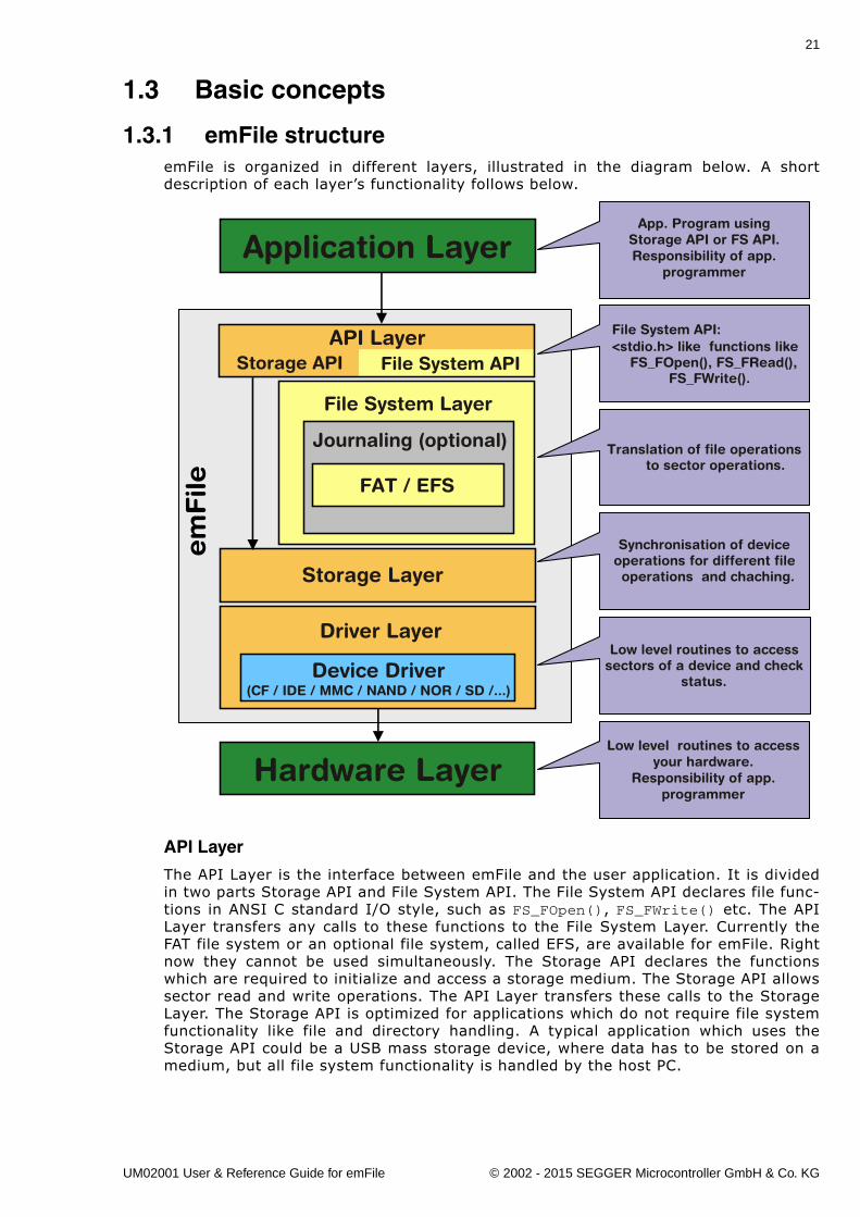
1.3.1 emFile structureemFile is organized in different layers, illustrated in the diagram below. A shortdescription of each layer�s functionality follows below.
API Layer
The API Layer is the interface between emFile and the user application. It is dividedin two parts Storage API and File System API. The File System API declares file func-tions in ANSI C standard I/O style, such as FS_FOpen(), FS_FWrite() etc. The APILayer transfers any calls to these functions to the File System Layer. Currently theFAT file system or an optional file system, called EFS, are available for emFile. Rightnow they cannot be used simultaneously. The Storage API declares the functionswhich are required to initialize and access a storage medium. The Storage API allowssector read and write operations. The API Layer transfers these calls to the StorageLayer. The Storage API is optimized for applications which do not require file systemfunctionality like file and directory handling. A typical application which uses theStorage API could be a USB mass storage device, where data has to be stored on amedium, but all file system functionality is handled by the host PC.
File System Layer
Storage Layer
Low level routines to access sectors of a device and check
status.
Synchronisation of device operations for different file operations and chaching.
Translation of file operationsto sector operations.
<stdio.h> like functions like FS_FOpen(), FS_FRead(),
FS_FWrite().
Application LayerApp. Program using
Storage API or FS API.Responsibility of app.
programmer
Hardware Layer
em
File
Low level routines to accessyour hardware.
Responsibility of app.programmer
File System API:
File System APIStorage APIAPI Layer
Device Driver(CF / IDE / MMC / NAND / NOR / SD /...)
Driver Layer
Journaling (optional)
FAT / EFS
UM02001 User & Reference Guide for emFile © 2002 - 2015 SEGGER Microcontroller GmbH & Co. KG
22 CHAPTER 1 Introduction to emFile
File System Layer
The file system layer translates file operations to logical block (sector) operations.After such a translation, the file system calls the logical block layer and specifies thecorresponding device driver for a device.
Storage Layer
The main purpose of the Storage Layer is to synchronize accesses to a device driver.Furthermore, it provides a simple interface for the File System API. The StorageLayer calls a device driver to perform a block operation. It also contains the cachemechanism.
Driver Layer
Device drivers are low-level routines that are used to access sectors of the deviceand to check status. It is hardware independent but depends on the storage medium.
Hardware Layer
These layer contains the low-level routines to access your hardware. These routinessimply read and store fixed length sectors. The structure of the device driver is sim-ple in order to allow easy integration of your own hardware.
1.3.2 Choice of file system type: FAT vs. EFSWithin emFile, there is a choice among two different file systems. The first, the FATfile system, is divided into three different sub types, FAT12, FAT16 and FAT32. Whilethe other, EFS, is a proprietary file system developed by Segger. Choosing a suitablefile system will depend on the environment in which the end application is to operate.
The FAT file system was developed by Microsoft to manage file segments, locateavailable clusters and reassemble file for use. Released in 1976, the first version ofthe FAT file system was FAT12, which is no longer widely used. It was created forextremely small storage devices. (The early version of FAT12 did not support manag-ing directories).
FAT16 is good for use on multiple operating systems because it is supported by allversions of Microsoft Windows, including DOS, OS/2 and Linux. The newest version,FAT32, improves upon the FAT16 file system by utilizing a partition/disk much moreefficiently. It is supported by Microsoft Windows 98/ME/2000/XP/2003 and Vista andas well on Linux based systems.
The EFS file system has been added to emFile as an alternative to the FAT file sys-tem. EFS has been designed for embedded devices. This file system reduces frag-mentation of the data by utilizing drive space more efficiently, while still offeringfaster access to embedded storage devices. Another benefit of EFS is that there areno issues concerning long file name (LFN) support. The FAT file system was notdesigned for long file name support, limiting names to twelve characters (8.3). LFNsupport may be added to any of the FAT file systems, but there are legal issues thatmust be settled with Microsoft before end applications make use of this feature. Longfile names are inherent to this proprietary file system relieving it of any legal issues.
1.3.3 Fail safetyFail safety is the feature of emFile that ensures the consistency of data in case ofunexpected loss of power during a write access to a storage medium. emFile will befail-safe only when both the file system (FAT/EFS) and the device driver are fail-safe.The journaling add-on of emFile to makes the FAT/EFS file systems fail-safe. Thedevice drivers of emFile are all from design fail-safe. You can find detailed informa-tion about how the fail-safety works on chapter Journaling (Add-on) on page 505 andof the description of individual device drivers.
UM02001 User & Reference Guide for emFile © 2002 - 2015 SEGGER Microcontroller GmbH & Co. KG
23
1.3.4 Wear levelingThis is a feature of the NAND and NOR flash device drivers that increase the lifetimeof a storage medium by ensuring that all the storage blocks are equally well used.The flash storage memories have a limited number of program/erase cycles, typicallyaround 100000. The manufacturers do not guarantee that the storage device willwork properly if this limit is exceeded. The wear leveling logic implemented in thedevice drivers tries to keep the number of program-erase cycles of a storage block aslow as possible. You can find additional information in the description of the respec-tive device drivers.
UM02001 User & Reference Guide for emFile © 2002 - 2015 SEGGER Microcontroller GmbH & Co. KG
24 CHAPTER 1 Introduction to emFile
1.4 Implementation notes
1.4.1 File system configurationThe file system is designed to be configurable at runtime. This has various advan-tages. Most of the configuration is done automatically; the linker links in only codethat is required. This concept allows to putting the file system in a library. The filesystem need not to be recompiled when the configuration changes, e.g. a differentdriver is used. Compile time configuration is kept to a minimum, primarily to selectthe level of multitasking support and the level of debug information. For detailedinformation about configuration of emFile, refer to Configuration of emFile onpage 471.
1.4.2 Runtime memory requirementsBecause the configuration is selected at runtime the amount of memory required isnot known at compile-time. For this reason a mechanism for runtime memory assign-ment is required. Runtime memory is typically allocated when required during theinitialization and in most embedded systems never freed.
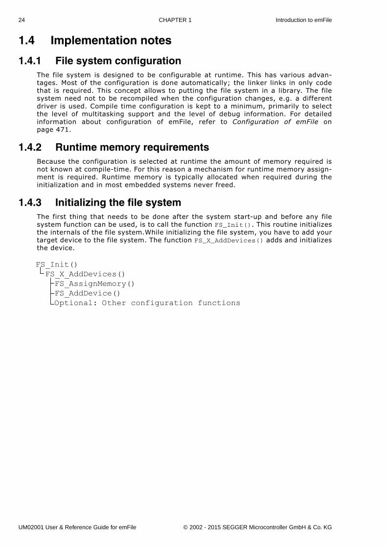
1.4.3 Initializing the file systemThe first thing that needs to be done after the system start-up and before any filesystem function can be used, is to call the function FS_Init(). This routine initializesthe internals of the file system.While initializing the file system, you have to add yourtarget device to the file system. The function FS_X_AddDevices() adds and initializesthe device.
FS_Init()FS_X_AddDevices()FS_AssignMemory()FS_AddDevice()Optional: Other configuration functions
UM02001 User & Reference Guide for emFile © 2002 - 2015 SEGGER Microcontroller GmbH & Co. KG
25
1.5 Development environment (compiler)The CPU used is of no importance; only an ANSI-compliant C compiler complying withat least one of the following international standard is required:
� ISO/IEC/ANSI 9899:1990 (C90) with support for C++ style comments (//)� ISO/IEC 9899:1999 (C99)� ISO/IEC 14882:1998 (C++)
If your compiler has some limitations, let us know and we will inform you if these willbe a problem when compiling the software. Any compiler for 16/32/64-bit CPUs orDSPs that we know of can be used; most 8-bit compilers can be used as well.
A C++ compiler is not required, but can be used. The application program can there-fore also be programmed in C++ if desired.
UM02001 User & Reference Guide for emFile © 2002 - 2015 SEGGER Microcontroller GmbH & Co. KG
26 CHAPTER 1 Introduction to emFile
UM02001 User & Reference Guide for emFile © 2002 - 2015 SEGGER Microcontroller GmbH & Co. KG
27
Chapter 2
Getting started
This chapter provides an introduction to using emFile. It explains how to use the Win-dows sample, which is an easy way to get a first project with emFile up and running.
UM02001 User & Reference Guide for emFile © 2002 - 2015 SEGGER Microcontroller GmbH & Co. KG

28 CHAPTER 2 Getting started
2.1 InstallationemFile is shipped as a CD-ROM or as a .zip file in electronic form.In order to install it, proceed as follows:
� If you received a CD, copy the entire contents to your hard drive into any folderof your choice. When copying, keep all files in their respective sub- directories.Make sure the files are not read-only after copying.
� If you received a .zip file, extract it to any folder of your choice, preserving thedirectory structure of the .zip file.
2.2 Using the Windows sampleIf you have MS Visual C++ 6.00 or any later version available, you will be able towork with a Windows sample project using emFile. Even if you do not have theMicrosoft compiler, you should read this chapter in order to understand how an appli-cation can use emFile.
2.2.1 Building the sample programOpen the workspace FS_Start.dsw with MS Visual Studio (for example double-click-ing it). There is no further configuration necessary. You should be able to build theapplication without any error or warning message.
2.2.2 Stepping through the sampleThe sample project uses the RAM disk driver for demonstration. The main function ofthe sample application Start.c calls the function MainTask(). MainTask() initializesthe file system and executes some basic file system operations.
The sample application Start.c step-by-step:
1. main.c calls MainTask(),2. MainTask() initializes and adds a device to emFile,3. checks if volume is low- level formatted and formats if required,4. checks if volume is high-level formatted and formats if required,5. outputs the volume name,6. calls FS_GetFreeVolumeSpace() and outputs the return value - the available free
space of the RAM disk - to console window,7. creates and opens a file test with write access (File.txt) on the device,8. writes 4 bytes into the file and closes the file handle or outputs an error mes-
sage,9. calls FS_GetFreeVolumeSpace() and outputs the return value - the available free
space of the RAM disk - again to console window,10. outputs an quit message and runs into an endless loop.
UM02001 User & Reference Guide for emFile © 2002 - 2015 SEGGER Microcontroller GmbH & Co. KG
29
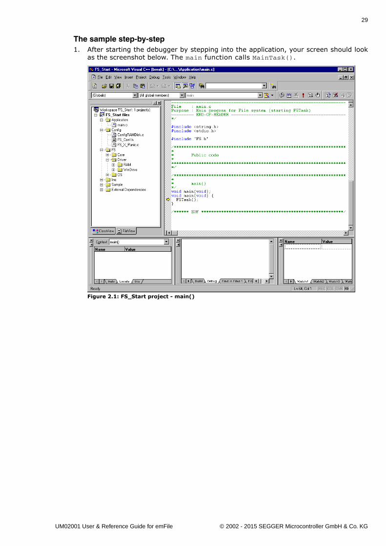
The sample step-by-step1. After starting the debugger by stepping into the application, your screen should look
as the screenshot below. The main function calls MainTask().
Figure 2.1: FS_Start project - main()
UM02001 User & Reference Guide for emFile © 2002 - 2015 SEGGER Microcontroller GmbH & Co. KG
30 CHAPTER 2 Getting started
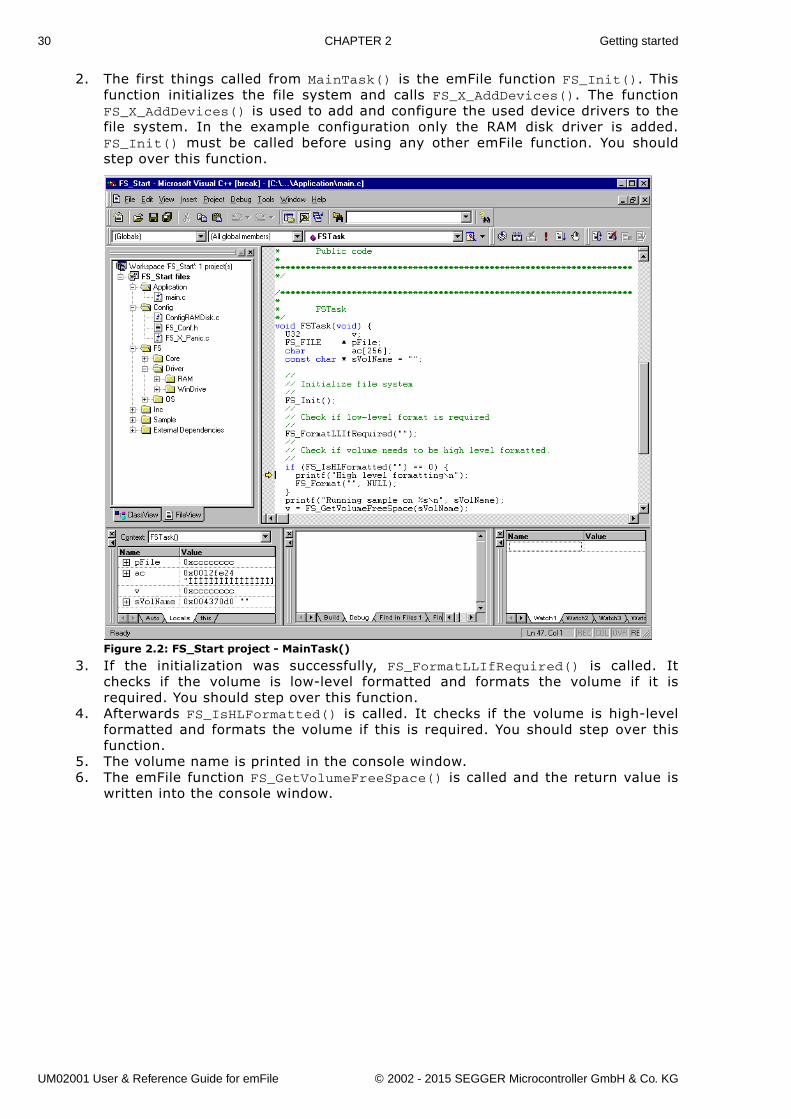
2. The first things called from MainTask() is the emFile function FS_Init(). Thisfunction initializes the file system and calls FS_X_AddDevices(). The functionFS_X_AddDevices() is used to add and configure the used device drivers to thefile system. In the example configuration only the RAM disk driver is added.FS_Init() must be called before using any other emFile function. You shouldstep over this function.
Figure 2.2: FS_Start project - MainTask()
3. If the initialization was successfully, FS_FormatLLIfRequired() is called. Itchecks if the volume is low-level formatted and formats the volume if it isrequired. You should step over this function.
4. Afterwards FS_IsHLFormatted() is called. It checks if the volume is high-levelformatted and formats the volume if this is required. You should step over thisfunction.
5. The volume name is printed in the console window.6. The emFile function FS_GetVolumeFreeSpace() is called and the return value is
written into the console window.
UM02001 User & Reference Guide for emFile © 2002 - 2015 SEGGER Microcontroller GmbH & Co. KG
31
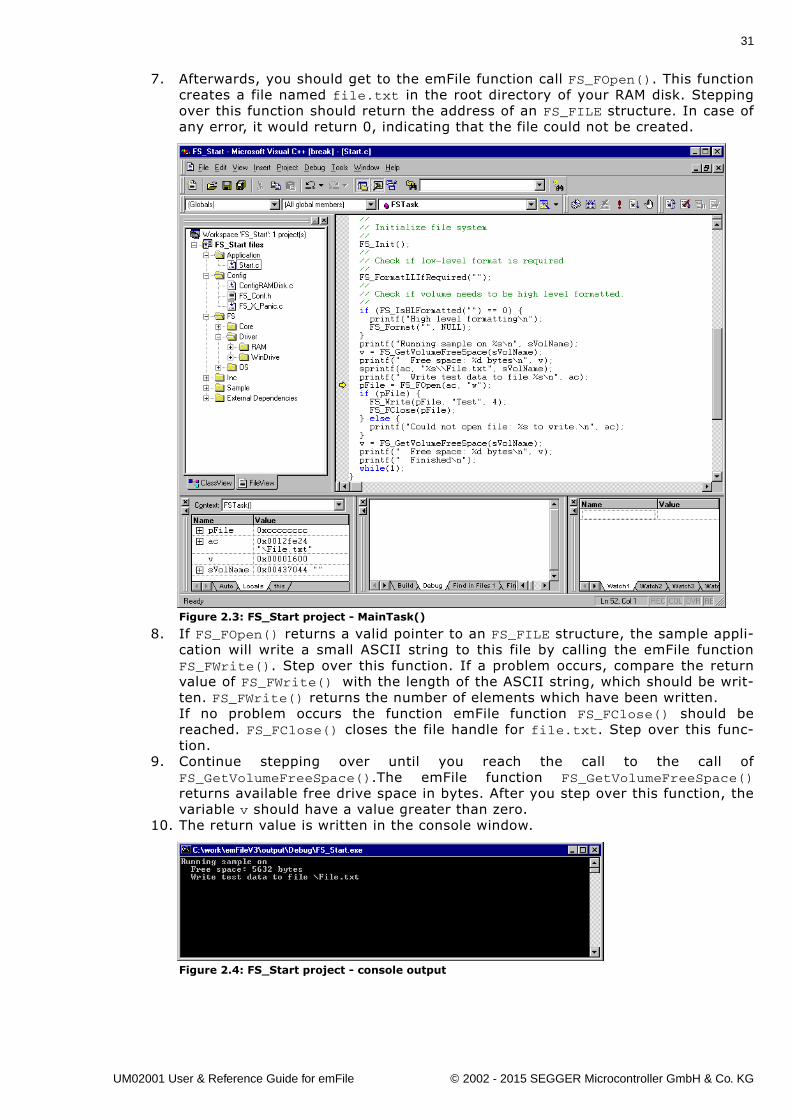
7. Afterwards, you should get to the emFile function call FS_FOpen(). This functioncreates a file named file.txt in the root directory of your RAM disk. Steppingover this function should return the address of an FS_FILE structure. In case ofany error, it would return 0, indicating that the file could not be created.
Figure 2.3: FS_Start project - MainTask()
8. If FS_FOpen() returns a valid pointer to an FS_FILE structure, the sample appli-cation will write a small ASCII string to this file by calling the emFile functionFS_FWrite(). Step over this function. If a problem occurs, compare the returnvalue of FS_FWrite() with the length of the ASCII string, which should be writ-ten. FS_FWrite() returns the number of elements which have been written. If no problem occurs the function emFile function FS_FClose() should bereached. FS_FClose() closes the file handle for file.txt. Step over this func-tion.
9. Continue stepping over until you reach the call to the call ofFS_GetVolumeFreeSpace().The emFile function FS_GetVolumeFreeSpace()returns available free drive space in bytes. After you step over this function, thevariable v should have a value greater than zero.
10. The return value is written in the console window.
Figure 2.4: FS_Start project - console output
UM02001 User & Reference Guide for emFile © 2002 - 2015 SEGGER Microcontroller GmbH & Co. KG
32 CHAPTER 2 Getting started
2.2.3 Further source code examplesFurther source code examples which demonstrate directory operations and perfor-mance measuring are available. All emFile source code examples are located inthe.\Sample\API\ directory under your emFile directory.
UM02001 User & Reference Guide for emFile © 2002 - 2015 SEGGER Microcontroller GmbH & Co. KG
33
Chapter 3
Running emFile on target hard-ware
This chapter explains how to integrate and run emFile on your target hardware.It explains this process step-by-step.
UM02001 User & Reference Guide for emFile © 2002 - 2015 SEGGER Microcontroller GmbH & Co. KG
34 CHAPTER 3 Running emFile on target hardware
Integrating emFile
The emFile default configuration contains a single device: a RAM disk. This shouldalways be the first step to check the proper function of emFile with your target hard-ware.
We assume that you are familiar with the tools you have selected for your project(compiler, project manager, linker, etc.). You should therefore be able to add files,add directories to the include search path, and so on. It is also assumed that you arefamiliar with the OS that you will be using in your target system (if you are usingone). In this document the IAR Embedded Workbench® IDE is used for all examplesand screenshots, but every other ANSI C toolchain can also be used. It is also possi-ble to use make files; in this case, when we say �add to the project�, this translatesinto �add to the make file�.
Procedure to follow
Integration of emFile is a relatively simple process, which consists of the followingsteps:
� Step 1: Creating a start project without emFile� Step 2: Adding emFile to the start project� Step 3: Adding the device driver� Step 4: Activating the driver� Step 5: Adjusting the RAM usage
UM02001 User & Reference Guide for emFile © 2002 - 2015 SEGGER Microcontroller GmbH & Co. KG
35
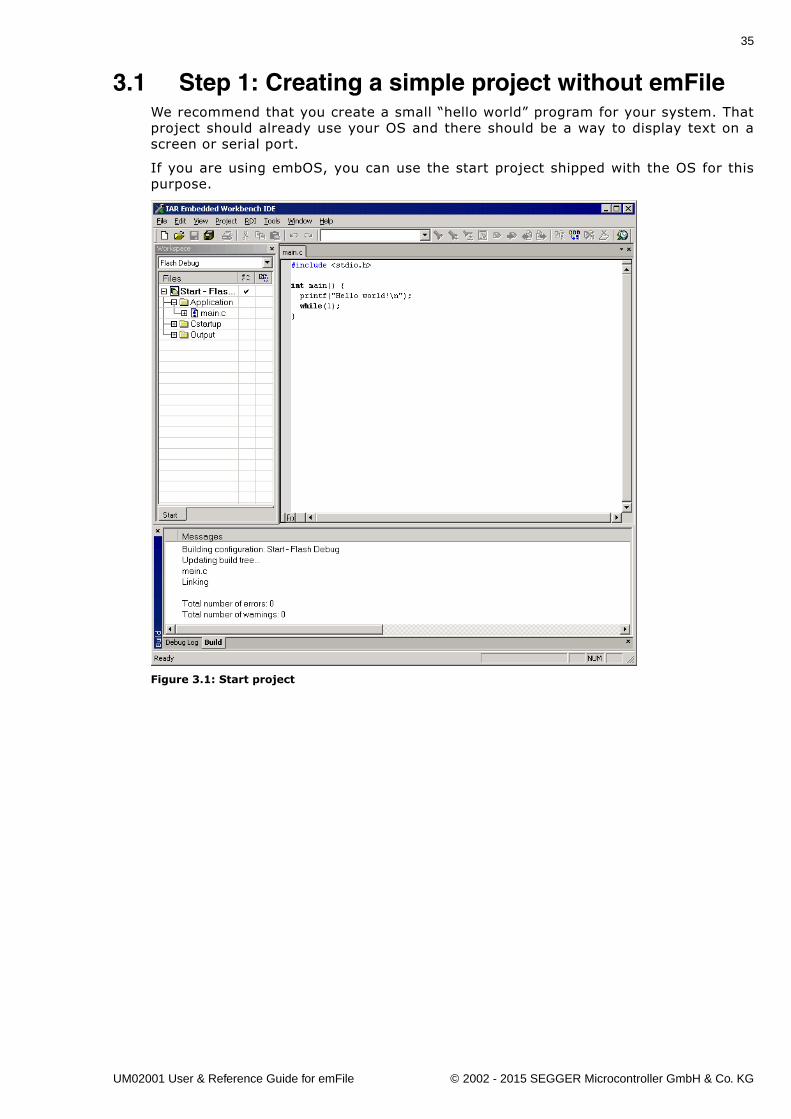
3.1 Step 1: Creating a simple project without emFileWe recommend that you create a small �hello world� program for your system. Thatproject should already use your OS and there should be a way to display text on ascreen or serial port.
If you are using embOS, you can use the start project shipped with the OS for thispurpose.
Figure 3.1: Start project
UM02001 User & Reference Guide for emFile © 2002 - 2015 SEGGER Microcontroller GmbH & Co. KG
36 CHAPTER 3 Running emFile on target hardware
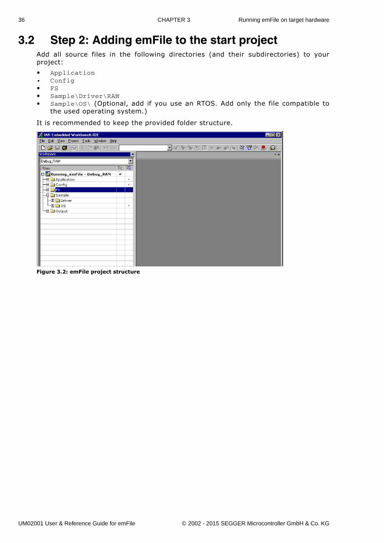
3.2 Step 2: Adding emFile to the start projectAdd all source files in the following directories (and their subdirectories) to yourproject:
� Application• Config� FS� Sample\Driver\RAM� Sample\OS\ (Optional, add if you use an RTOS. Add only the file compatible to
the used operating system.)
It is recommended to keep the provided folder structure.
Figure 3.2: emFile project structure
UM02001 User & Reference Guide for emFile © 2002 - 2015 SEGGER Microcontroller GmbH & Co. KG
37
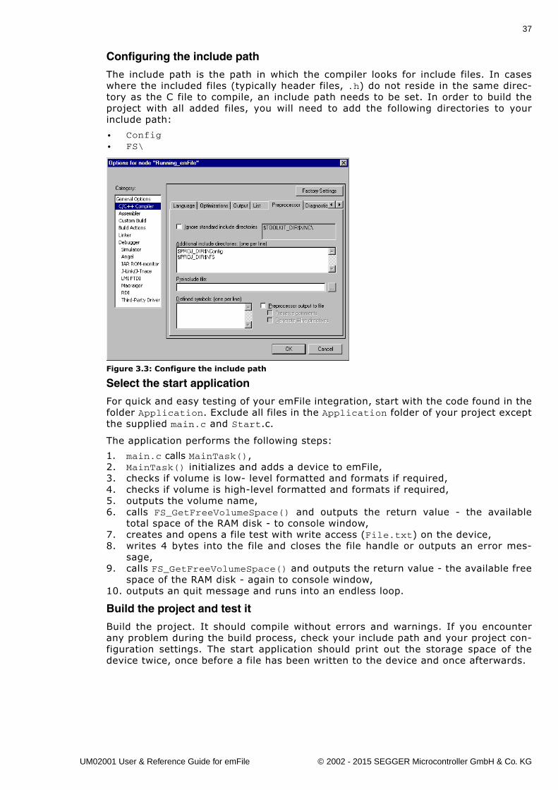
Configuring the include path
The include path is the path in which the compiler looks for include files. In caseswhere the included files (typically header files, .h) do not reside in the same direc-tory as the C file to compile, an include path needs to be set. In order to build theproject with all added files, you will need to add the following directories to yourinclude path:
• Config• FS\
Figure 3.3: Configure the include path
Select the start application
For quick and easy testing of your emFile integration, start with the code found in thefolder Application. Exclude all files in the Application folder of your project exceptthe supplied main.c and Start.c.
The application performs the following steps:
1. main.c calls MainTask(),2. MainTask() initializes and adds a device to emFile,3. checks if volume is low- level formatted and formats if required,4. checks if volume is high-level formatted and formats if required,5. outputs the volume name,6. calls FS_GetFreeVolumeSpace() and outputs the return value - the available
total space of the RAM disk - to console window,7. creates and opens a file test with write access (File.txt) on the device,8. writes 4 bytes into the file and closes the file handle or outputs an error mes-
sage,9. calls FS_GetFreeVolumeSpace() and outputs the return value - the available free
space of the RAM disk - again to console window,10. outputs an quit message and runs into an endless loop.
Build the project and test it
Build the project. It should compile without errors and warnings. If you encounterany problem during the build process, check your include path and your project con-figuration settings. The start application should print out the storage space of thedevice twice, once before a file has been written to the device and once afterwards.
UM02001 User & Reference Guide for emFile © 2002 - 2015 SEGGER Microcontroller GmbH & Co. KG
38 CHAPTER 3 Running emFile on target hardware
3.3 Step 3: Adding the device driverTo configure emFile with a device driver 2 things need to be done at the same time:
� Adding device driver source to project� Adding hardware routines to project
Every recommended step is explained in the following sections. For example, theimplementation of the MMC/SD driver is shown, but all steps should be easy to adapton every other device driver implementation.
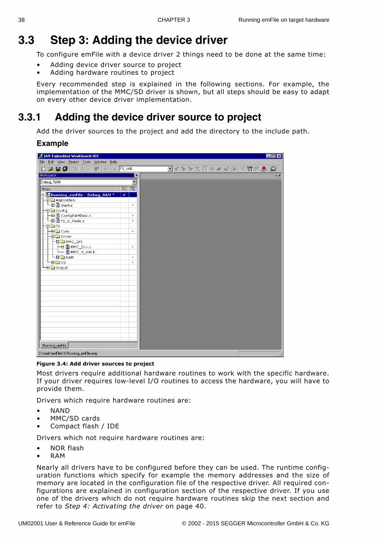
3.3.1 Adding the device driver source to projectAdd the driver sources to the project and add the directory to the include path.
Example
Figure 3.4: Add driver sources to project
Most drivers require additional hardware routines to work with the specific hardware.If your driver requires low-level I/O routines to access the hardware, you will have toprovide them.
Drivers which require hardware routines are:
� NAND� MMC/SD cards� Compact flash / IDE
Drivers which not require hardware routines are:
� NOR flash� RAM
Nearly all drivers have to be configured before they can be used. The runtime config-uration functions which specify for example the memory addresses and the size ofmemory are located in the configuration file of the respective driver. All required con-figurations are explained in configuration section of the respective driver. If you useone of the drivers which do not require hardware routines skip the next section andrefer to Step 4: Activating the driver on page 40.
UM02001 User & Reference Guide for emFile © 2002 - 2015 SEGGER Microcontroller GmbH & Co. KG
39
3.3.2 Adding hardware routines to projectA template with empty function bodies and in most cases one ore more sampleimplementations are supplied for every driver which requires hardware routines. Theeasiest way to start is to use one of the ready-to-use samples. The ready-to-usesamples can be found in the subfolders of Sample\Driver\<DRIVER_DIR>\. Youshould check the Readme.txt file located in the driver directory to see which samplesare included. If there is one which is a good or close match for your hardware, itshould be used. Otherwise, use the template to implement the hardware routines.
The template is a skeleton driver which contains empty implementations of therequired functions and is the ideal base to start the implementation of hardware spe-cific I/O routines.
What to do
Copy the compatible hardware function sample or the template into a subdirectory ofyour work directory and add it to your project. The template file is located in theSample\Driver\<DRIVER_DIR>\ directory; the example implementations are locatedin the respective directories. If you start the implementation of hardware routineswith the hardware routine template, refer to Device drivers on page 213 for detailedinformation about the implementation of the driver specific hardware functions, elserefer to section Step 4: Activating the driver on page 40.
Note: You cannot run and test the project with the new driver on your hardwareas long as you have not added the proper configuration file for the driver to yourproject. Refer to section Step 4: Activating the driver on page 40 for more informa-tion about the activation of the driver with the configuration file.
UM02001 User & Reference Guide for emFile © 2002 - 2015 SEGGER Microcontroller GmbH & Co. KG
40 CHAPTER 3 Running emFile on target hardware
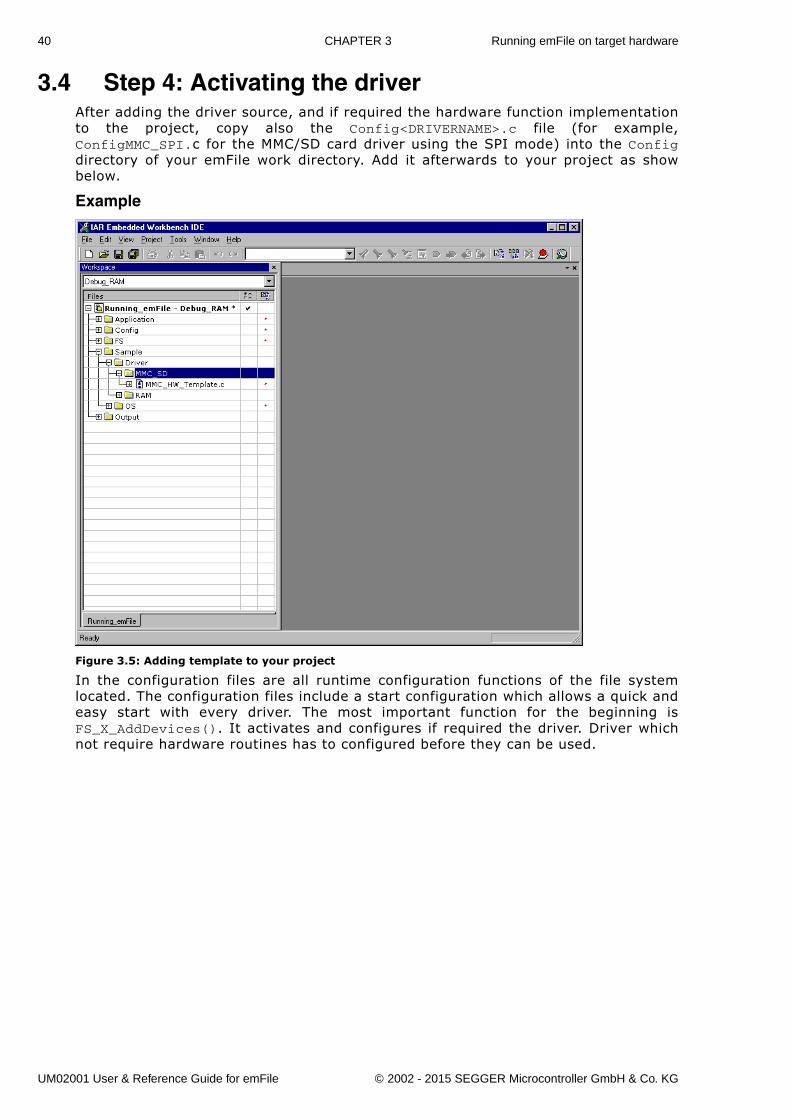
3.4 Step 4: Activating the driver After adding the driver source, and if required the hardware function implementationto the project, copy also the Config<DRIVERNAME>.c file (for example,ConfigMMC_SPI.c for the MMC/SD card driver using the SPI mode) into the Configdirectory of your emFile work directory. Add it afterwards to your project as showbelow.
Example
Figure 3.5: Adding template to your project
In the configuration files are all runtime configuration functions of the file systemlocated. The configuration files include a start configuration which allows a quick andeasy start with every driver. The most important function for the beginning isFS_X_AddDevices(). It activates and configures if required the driver. Driver whichnot require hardware routines has to configured before they can be used.
UM02001 User & Reference Guide for emFile © 2002 - 2015 SEGGER Microcontroller GmbH & Co. KG
41
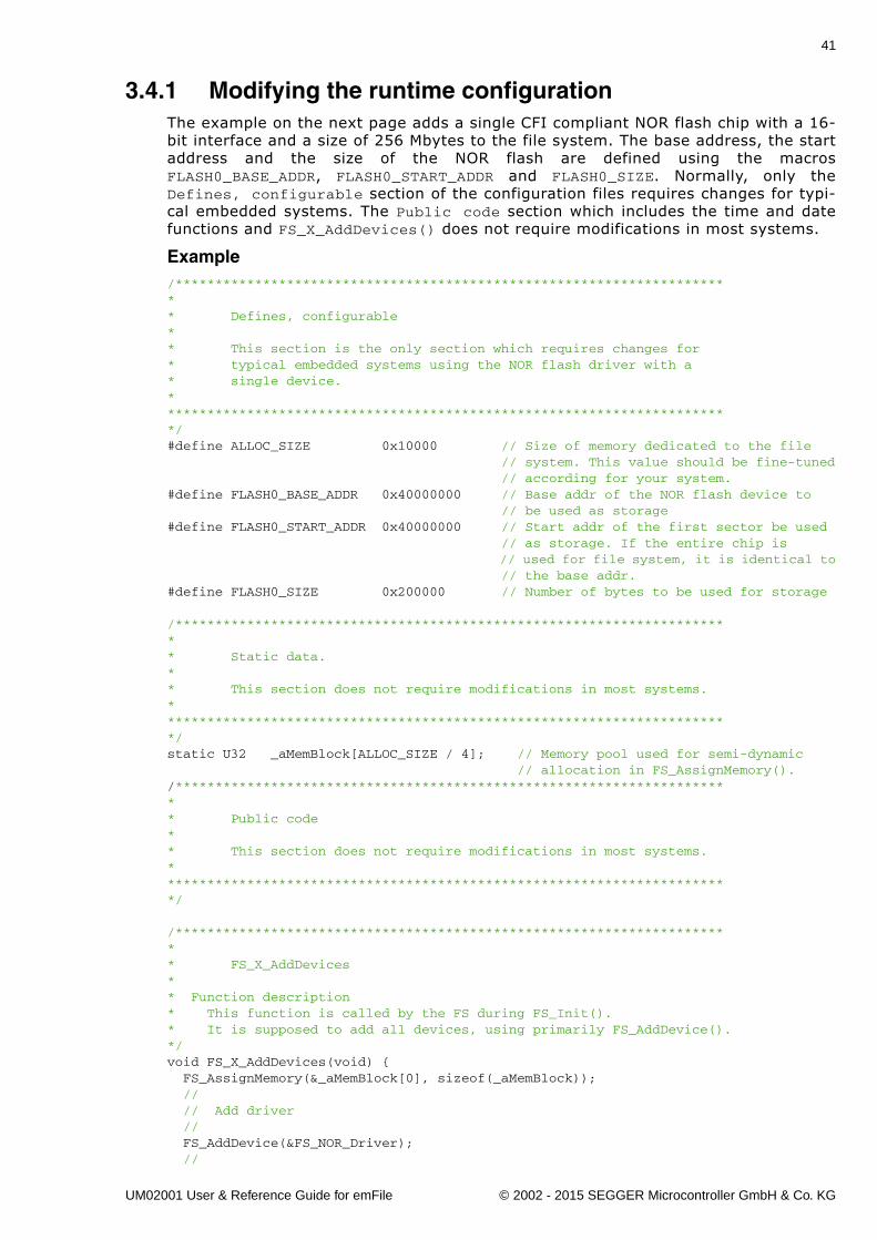
3.4.1 Modifying the runtime configurationThe example on the next page adds a single CFI compliant NOR flash chip with a 16-bit interface and a size of 256 Mbytes to the file system. The base address, the startaddress and the size of the NOR flash are defined using the macrosFLASH0_BASE_ADDR, FLASH0_START_ADDR and FLASH0_SIZE. Normally, only theDefines, configurable section of the configuration files requires changes for typi-cal embedded systems. The Public code section which includes the time and datefunctions and FS_X_AddDevices() does not require modifications in most systems.
Example/*********************************************************************** Defines, configurable** This section is the only section which requires changes for * typical embedded systems using the NOR flash driver with a* single device.************************************************************************/#define ALLOC_SIZE 0x10000 // Size of memory dedicated to the file // system. This value should be fine-tuned // according for your system.#define FLASH0_BASE_ADDR 0x40000000 // Base addr of the NOR flash device to // be used as storage#define FLASH0_START_ADDR 0x40000000 // Start addr of the first sector be used // as storage. If the entire chip is // used for file system, it is identical to // the base addr.#define FLASH0_SIZE 0x200000 // Number of bytes to be used for storage
/*********************************************************************** Static data.** This section does not require modifications in most systems.************************************************************************/static U32 _aMemBlock[ALLOC_SIZE / 4]; // Memory pool used for semi-dynamic // allocation in FS_AssignMemory()./*********************************************************************** Public code** This section does not require modifications in most systems.************************************************************************/
/*********************************************************************** FS_X_AddDevices** Function description* This function is called by the FS during FS_Init().* It is supposed to add all devices, using primarily FS_AddDevice().*/void FS_X_AddDevices(void) { FS_AssignMemory(&_aMemBlock[0], sizeof(_aMemBlock)); // // Add driver // FS_AddDevice(&FS_NOR_Driver); //
UM02001 User & Reference Guide for emFile © 2002 - 2015 SEGGER Microcontroller GmbH & Co. KG
42 CHAPTER 3 Running emFile on target hardware
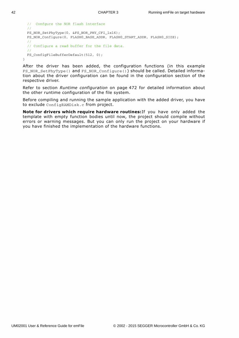
// Confgure the NOR flash interface // FS_NOR_SetPhyType(0, &FS_NOR_PHY_CFI_1x16); FS_NOR_Configure(0, FLASH0_BASE_ADDR, FLASH0_START_ADDR, FLASH0_SIZE); // // Configure a read buffer for the file data. // FS_ConfigFileBufferDefault(512, 0);}
After the driver has been added, the configuration functions (in this exampleFS_NOR_SetPhyType() and FS_NOR_Configure()) should be called. Detailed informa-tion about the driver configuration can be found in the configuration section of therespective driver.
Refer to section Runtime configuration on page 472 for detailed information aboutthe other runtime configuration of the file system.
Before compiling and running the sample application with the added driver, you haveto exclude ConfigRAMDisk.c from project.
Note for drivers which require hardware routines:If you have only added thetemplate with empty function bodies until now, the project should compile withouterrors or warning messages. But you can only run the project on your hardware ifyou have finished the implementation of the hardware functions.
UM02001 User & Reference Guide for emFile © 2002 - 2015 SEGGER Microcontroller GmbH & Co. KG
43
3.5 Step 5: Adjusting the RAM usageThe file system needs RAM for management purposes in various places. The amountof RAM required depends primarily on the configuration, especially the drivers used.The drivers which have their own level of management (such as NOR / NAND drivers)in general need more RAM than the �simple� drivers for hard drives, compact flash orSD cards.
Every driver needs to allocate RAM. The file system allocates RAM in the initializationphase and holds it while the file system is running. The macro ALLOC_SIZE which islocated in the respective driver configuration file specifies the size of RAM used bythe file system. This value should be fine-tuned according to the requirements ofyour target system.
What to do
Per default, ALLOC_SIZE is set to a value which should be appropriate for most targetsystems. Nevertheless, you should adjust it in order to avoid wasting. Once your filesystem project is up and running, you can check the real RAM requirement of thedriver with the public auxiliary variable FS_NumBytesAllocated which is also locatedin the configuration file of the respective driver. Check the value ofFS_NumBytesAllocated after the initialization of the file system (FS_Init()) andafter a volume has been mounted. At this point FS_NumBytesAllocated can be usedas reference for the dynamic memory usage of emFile. You should reserve a fewmore bytes for emFile as the value of FS_NumBytesAllocated is at this point, sinceevery file which is opened needs dynamic memory for maintenance information. Formore information about resource usage of the file handlers, please refer to DynamicRAM requirements on page 501.
Note: If you define ALLOC_SIZE with a value which is smaller than the appropri-ate size, the file system will run into FS_X_Panic(). If you define ALLOC_SIZE with avalue which is above the limits of your target system, the linker will give an errorduring the build process of the project.
UM02001 User & Reference Guide for emFile © 2002 - 2015 SEGGER Microcontroller GmbH & Co. KG
44 CHAPTER 3 Running emFile on target hardware
UM02001 User & Reference Guide for emFile © 2002 - 2015 SEGGER Microcontroller GmbH & Co. KG
45
Chapter 4
API functions
In this chapter, you will find a description of each emFile API functions. An applicationshould only access emFile by these functions.
UM02001 User & Reference Guide for emFile © 2002 - 2015 SEGGER Microcontroller GmbH & Co. KG
46 CHAPTER 4 API functions
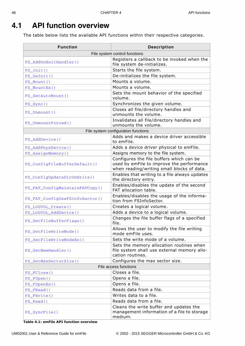
4.1 API function overviewThe table below lists the available API functions within their respective categories.
Function Description
File system control functions
FS_AddOnExitHandler()Registers a callback to be invoked when the file system de-initializes.
FS_Init() Starts the file system.FS_DeInit() De-initializes the file system.FS_Mount() Mounts a volume.FS_MountEx() Mounts a volume.
FS_SetAutoMount()Sets the mount behavior of the specified volume.
FS_Sync() Synchronizes the given volume.
FS_Unmount()Closes all file/directory handles and unmounts the volume.
FS_UnmountForced()Invalidates all file/directory handles and unmounts the volume.
File system configuration functions
FS_AddDevice()Adds and makes a device driver accessible to emFile.
FS_AddPhysDevice() Adds a device driver physical to emFile.FS_AssignMemory() Assigns memory to the file system.
FS_ConfigFileBufferDefault()Configures the file buffers which can be used by emFile to improve the performance when reading/writing small blocks of data.
FS_ConfigUpdateDirOnWrite()Enables that writing to a file always updates the directory entry.
FS_FAT_ConfigMaintainFATCopy()Enables/disables the update of the second FAT allocation table.
FS_FAT_ConfigUseFSInfoSector()Enables/disables the usage of the informa-tion from FSInfoSector.
FS_LOGVOL_Create() Creates a logical volume.FS_LOGVOL_AddDevice() Adds a device to a logical volume.
FS_SetFileBufferFlags()Changes the file buffer flags of a specified file.
FS_SetFileWriteMode()Allows the user to modify the file writing mode emFile uses.
FS_SetFileWriteModeEx() Sets the write mode of a volume.
FS_SetMemHandler()Sets the memory allocation routines when file system shall use external memory allo-cation routines.
FS_SetMaxSectorSize() Configures the max sector size.File access functions
FS_FClose() Closes a file.FS_FOpen() Opens a file.FS_FOpenEx() Opens a file.FS_FRead() Reads data from a file.FS_FWrite() Writes data to a file.FS_Read() Reads data from a file.
FS_SyncFile()Cleans the write buffer and updates the management information of a file to storage medium.
Table 4.1: emFile API function overview
UM02001 User & Reference Guide for emFile © 2002 - 2015 SEGGER Microcontroller GmbH & Co. KG
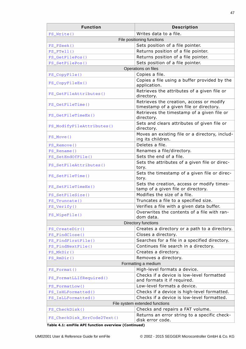
47
FS_Write() Writes data to a file.File positioning functions
FS_FSeek() Sets position of a file pointer.FS_FTell() Returns position of a file pointer.FS_GetFilePos() Returns position of a file pointer.FS_SetFilePos() Sets position of a file pointer.
Operations on filesFS_CopyFile() Copies a file.
FS_CopyFileEx()Copies a file using a buffer provided by the application.
FS_GetFileAttributes()Retrieves the attributes of a given file or directory.
FS_GetFileTime()Retrieves the creation, access or modify timestamp of a given file or directory.
FS_GetFileTimeEx()Retrieves the timestamp of a given file or directory.
FS_ModifyFileAttributes()Sets and clears attributes of given file or directory.
FS_Move()Moves an existing file or a directory, includ-ing its children.
FS_Remove() Deletes a file.FS_Rename() Renames a file/directory.FS_SetEndOfFile() Sets the end of a file.
FS_SetFileAttributes()Sets the attributes of a given file or direc-tory.
FS_SetFileTime()Sets the timestamp of a given file or direc-tory.
FS_SetFileTimeEx()Sets the creation, access or modify times-tamp of a given file or directory.
FS_SetFileSize() Modifies the size of a file.FS_Truncate() Truncates a file to a specified size.FS_Verify() Verifies a file with a given data buffer.
FS_WipeFile()Overwrites the contents of a file with ran-dom data.
Directory functionsFS_CreateDir() Creates a directory or a path to a directory.FS_FindClose() Closes a directory.FS_FindFirstFile() Searches for a file in a specified directory.FS_FindNextFile() Continues file search in a directory.FS_MkDir() Creates a directory.FS_RmDir() Removes a directory.
Formatting a mediumFS_Format() High-level formats a device.
FS_FormatLLIfRequired()Checks if a device is low-level formatted and formats it if required.
FS_FormatLow() Low-level formats a device.FS_IsHLFormatted() Checks if a device is high-level formatted.FS_IsLLFormatted() Checks if a device is low-level formatted.
File system extended functionsFS_CheckDisk() Checks and repairs a FAT volume.
FS_CheckDisk_ErrCode2Text()Returns an error string to a specific check-disk error code.
Function Description
Table 4.1: emFile API function overview (Continued)
UM02001 User & Reference Guide for emFile © 2002 - 2015 SEGGER Microcontroller GmbH & Co. KG
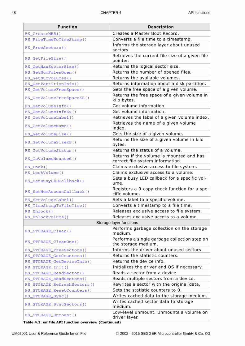
48 CHAPTER 4 API functions
FS_CreateMBR() Creates a Master Boot Record.FS_FileTimeToTimeStamp() Converts a file time to a timestamp.
FS_FreeSectors()Informs the storage layer about unused sectors.
FS_GetFileSize()Retrieves the current file size of a given file pointer.
FS_GetMaxSectorSize() Returns the logical sector size.FS_GetNumFilesOpen() Returns the number of opened files.FS_GetNumVolumes() Returns the available volumes.FS_GetPartitionInfo() Returns information about a disk partition.FS_GetVolumeFreeSpace() Gets the free space of a given volume.
FS_GetVolumeFreeSpaceKB()Returns the free space of a given volume in kilo bytes.
FS_GetVolumeInfo() Get volume information.FS_GetVolumeInfoEx() Get volume information.FS_GetVolumeLabel() Retrieves the label of a given volume index.
FS_GetVolumeName()Retrieves the name of a given volume index.
FS_GetVolumeSize() Gets the size of a given volume.
FS_GetVolumeSizeKB()Returns the size of a given volume in kilo bytes.
FS_GetVolumeStatus() Returns the status of a volume.
FS_IsVolumeMounted()Returns if the volume is mounted and has correct file system information.
FS_Lock() Claims exclusive access to file system.FS_LockVolume() Claims exclusive access to a volume.
FS_SetBusyLEDCallback()Sets a busy LED callback for a specific vol-ume.
FS_SetMemAccessCallback()Registers a 0-copy check function for a spe-cific volume.
FS_SetVolumeLabel() Sets a label to a specific volume.FS_TimeStampToFileTime() Converts a timestamp to a file time.FS_Unlock() Releases exclusive access to file system.FS_UnlockVolume() Releases exclusive access to a volume.
Storage layer functions
FS_STORAGE_Clean()Performs garbage collection on the storage medium.
FS_STORAGE_CleanOne()Performs a single garbage collection step on the storage medium.
FS_STORAGE_FreeSectors() Informs the driver about unused sectors.FS_STORAGE_GetCounters() Returns the statistic counters.FS_STORAGE_GetDeviceInfo() Returns the device info.FS_STORAGE_Init() Initializes the driver and OS if necessary.FS_STORAGE_ReadSector() Reads a sector from a device.FS_STORAGE_ReadSectors() Reads multiple sectors from a device.FS_STORAGE_RefreshSectors() Rewrites a sector with the original data.FS_STORAGE_ResetCounters() Sets the statistic counters to 0.FS_STORAGE_Sync() Writes cached data to the storage medium.
FS_STORAGE_SyncSectors()Writes cached sector data to storage medium.
FS_STORAGE_Unmount()Low-level unmount. Unmounts a volume on driver layer.
Function Description
Table 4.1: emFile API function overview (Continued)
UM02001 User & Reference Guide for emFile © 2002 - 2015 SEGGER Microcontroller GmbH & Co. KG
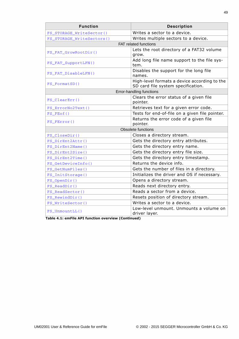
49
FS_STORAGE_WriteSector() Writes a sector to a device.FS_STORAGE_WriteSectors() Writes multiple sectors to a device.
FAT related functions
FS_FAT_GrowRootDir()Lets the root directory of a FAT32 volume grow.
FS_FAT_SupportLFN()Add long file name support to the file sys-tem.
FS_FAT_DisableLFN()Disables the support for the long file names.
FS_FormatSD()High-level formats a device according to the SD card file system specification.
Error-handling functions
FS_ClearErr()Clears the error status of a given file pointer.
FS_ErrorNo2Text() Retrieves text for a given error code.FS_FEof() Tests for end-of-file on a given file pointer.
FS_FError()Returns the error code of a given file pointer.
Obsolete functionsFS_CloseDir() Closes a directory stream.FS_DirEnt2Attr() Gets the directory entry attributes.FS_DirEnt2Name() Gets the directory entry name.FS_DirEnt2Size() Gets the directory entry file size.FS_DirEnt2Time() Gets the directory entry timestamp.FS_GetDeviceInfo() Returns the device info.FS_GetNumFiles() Gets the number of files in a directory.FS_InitStorage() Initializes the driver and OS if necessary.FS_OpenDir() Opens a directory stream.FS_ReadDir() Reads next directory entry.FS_ReadSector() Reads a sector from a device.FS_RewindDir() Resets position of directory stream.FS_WriteSector() Writes a sector to a device.
FS_UnmountLL()Low-level unmount. Unmounts a volume on driver layer.
Function Description
Table 4.1: emFile API function overview (Continued)
UM02001 User & Reference Guide for emFile © 2002 - 2015 SEGGER Microcontroller GmbH & Co. KG
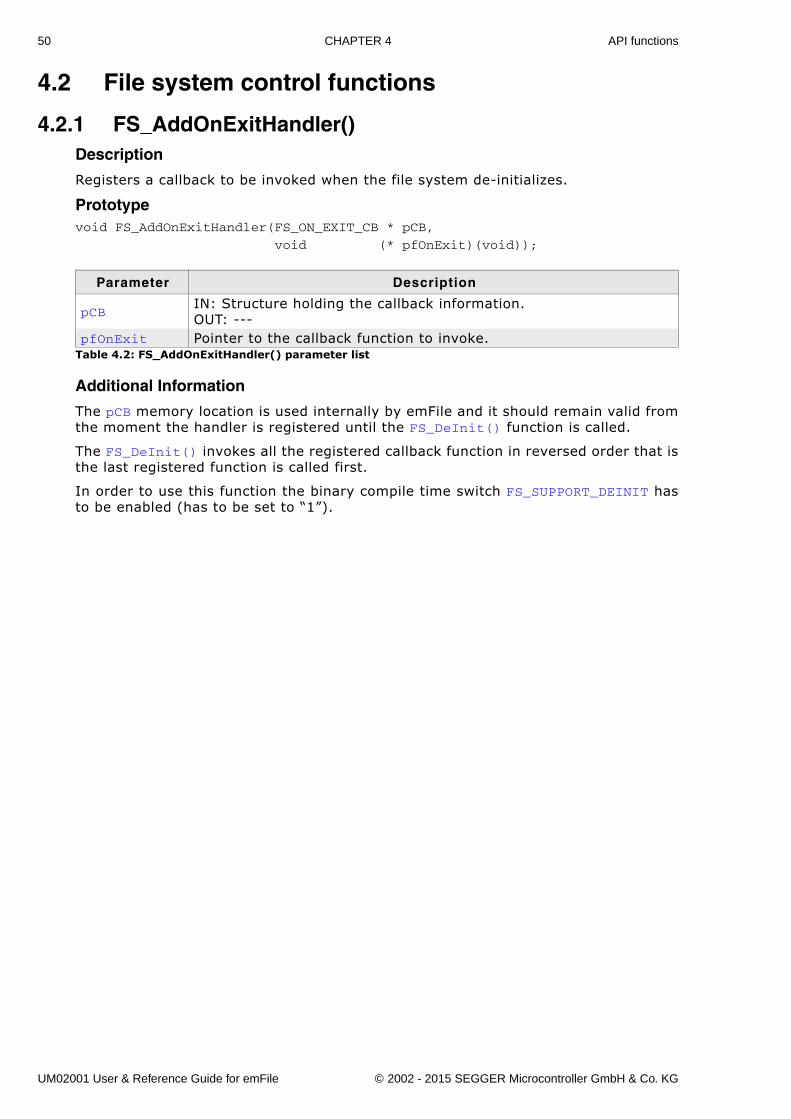
50 CHAPTER 4 API functions
4.2 File system control functions
4.2.1 FS_AddOnExitHandler()Description
Registers a callback to be invoked when the file system de-initializes.
Prototypevoid FS_AddOnExitHandler(FS_ON_EXIT_CB * pCB,
void (* pfOnExit)(void));
Additional Information
The pCB memory location is used internally by emFile and it should remain valid fromthe moment the handler is registered until the FS_DeInit() function is called.
The FS_DeInit() invokes all the registered callback function in reversed order that isthe last registered function is called first.
In order to use this function the binary compile time switch FS_SUPPORT_DEINIT hasto be enabled (has to be set to �1�).
Parameter Description
pCBIN: Structure holding the callback information.OUT: ---
pfOnExit Pointer to the callback function to invoke.Table 4.2: FS_AddOnExitHandler() parameter list
UM02001 User & Reference Guide for emFile © 2002 - 2015 SEGGER Microcontroller GmbH & Co. KG
51
4.2.2 FS_Init()Description
Starts the file system.
Prototypevoid FS_Init(void);
Additional Information
FS_Init() initializes the file system and creates resources required for an OS inte-gration of emFile. This function must be called before any other emFile function.
Example
#include "FS.h"
void main(void) { FS_Init(); // // Access file system // }
UM02001 User & Reference Guide for emFile © 2002 - 2015 SEGGER Microcontroller GmbH & Co. KG
52 CHAPTER 4 API functions
4.2.3 FS_DeInit()Description
De-initializes the file system. All resources which are occupied by the file system, arefreed. All static variables for each layer are reset in order to guarantee that emFile isin a known state after de-initialization.
Please use this function when you are planning to reset emFile during run-time. Forexample this is the case if your target application uses a software reboot which re-initializes the target application.
Prototypevoid FS_DeInit(void);
Additional information
In order to use this function the binary compile time switch FS_SUPPORT_DEINIT hasto be enabled (has to be set to �1�).
UM02001 User & Reference Guide for emFile © 2002 - 2015 SEGGER Microcontroller GmbH & Co. KG
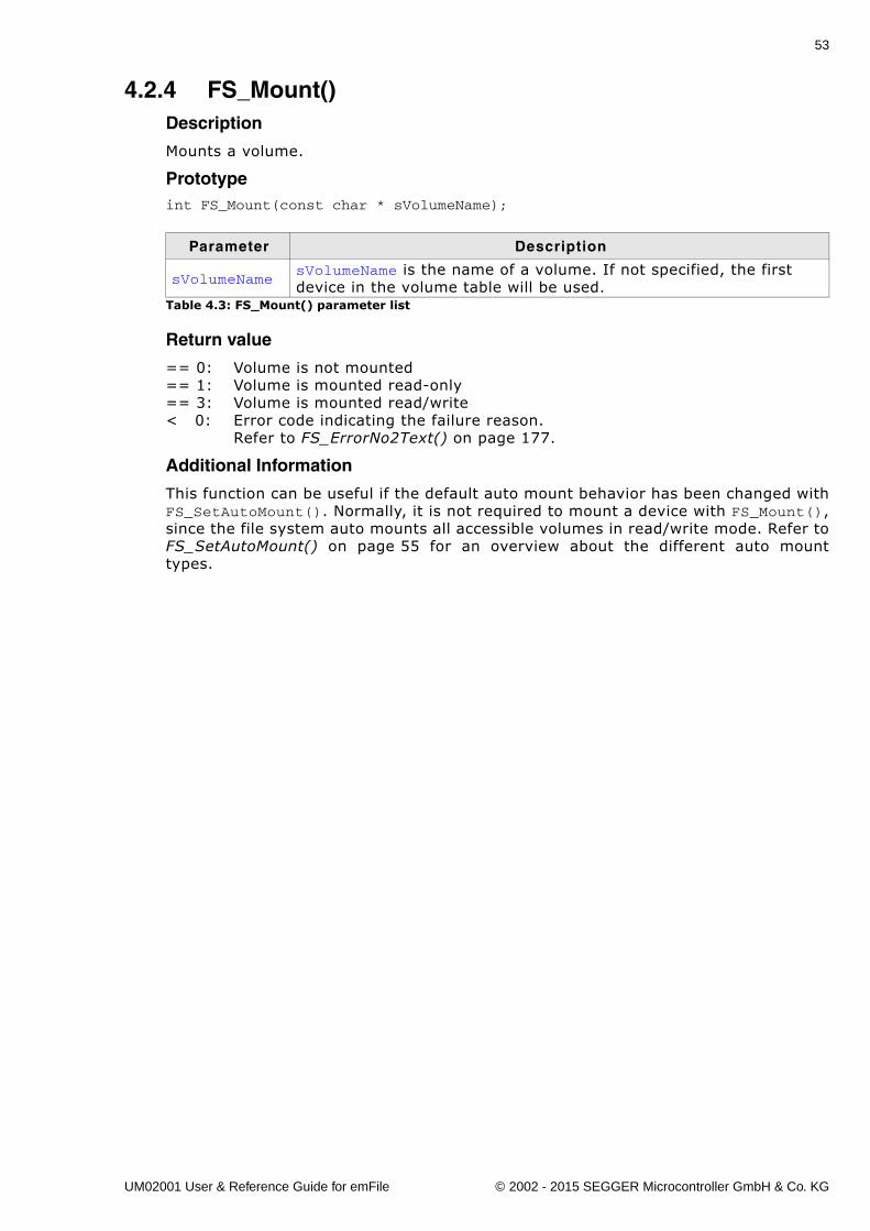
53
4.2.4 FS_Mount()Description
Mounts a volume.
Prototypeint FS_Mount(const char * sVolumeName);
Return value
== 0: Volume is not mounted== 1: Volume is mounted read-only== 3: Volume is mounted read/write< 0: Error code indicating the failure reason.
Refer to FS_ErrorNo2Text() on page 177.
Additional Information
This function can be useful if the default auto mount behavior has been changed withFS_SetAutoMount(). Normally, it is not required to mount a device with FS_Mount(),since the file system auto mounts all accessible volumes in read/write mode. Refer toFS_SetAutoMount() on page 55 for an overview about the different auto mounttypes.
Parameter Description
sVolumeNamesVolumeName is the name of a volume. If not specified, the first device in the volume table will be used.
Table 4.3: FS_Mount() parameter list
UM02001 User & Reference Guide for emFile © 2002 - 2015 SEGGER Microcontroller GmbH & Co. KG
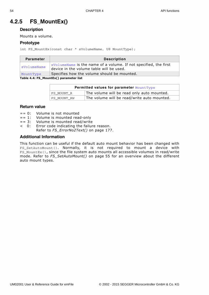
54 CHAPTER 4 API functions
4.2.5 FS_MountEx()Description
Mounts a volume.
Prototypeint FS_MountEx(const char * sVolumeName, U8 MountType);
Return value
== 0: Volume is not mounted== 1: Volume is mounted read-only== 3: Volume is mounted read/write< 0: Error code indicating the failure reason.
Refer to FS_ErrorNo2Text() on page 177.
Additional Information
This function can be useful if the default auto mount behavior has been changed withFS_SetAutoMount(). Normally, it is not required to mount a device withFS_MountEx(), since the file system auto mounts all accessible volumes in read/writemode. Refer to FS_SetAutoMount() on page 55 for an overview about the differentauto mount types.
Parameter Description
sVolumeNamesVolumeName is the name of a volume. If not specified, the first device in the volume table will be used.
MountType Specifies how the volume should be mounted.Table 4.4: FS_MountEx() parameter list
Permitted values for parameter MountType
FS_MOUNT_R The volume will be read only auto mounted.FS_MOUNT_RW The volume will be read/write auto mounted.
UM02001 User & Reference Guide for emFile © 2002 - 2015 SEGGER Microcontroller GmbH & Co. KG
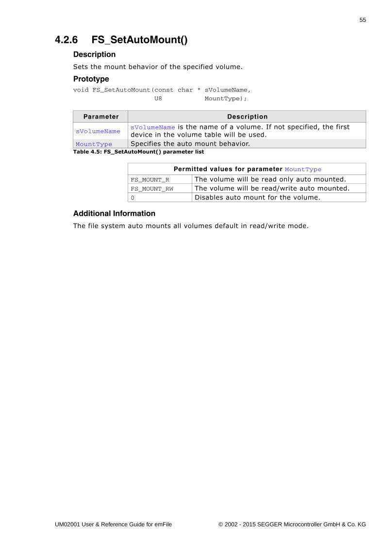
55
4.2.6 FS_SetAutoMount()Description
Sets the mount behavior of the specified volume.
Prototypevoid FS_SetAutoMount(const char * sVolumeName,
U8 MountType);
Additional Information
The file system auto mounts all volumes default in read/write mode.
Parameter Description
sVolumeNamesVolumeName is the name of a volume. If not specified, the first device in the volume table will be used.
MountType Specifies the auto mount behavior. Table 4.5: FS_SetAutoMount() parameter list
Permitted values for parameter MountType
FS_MOUNT_R The volume will be read only auto mounted.FS_MOUNT_RW The volume will be read/write auto mounted.0 Disables auto mount for the volume.
UM02001 User & Reference Guide for emFile © 2002 - 2015 SEGGER Microcontroller GmbH & Co. KG
56 CHAPTER 4 API functions
4.2.7 FS_Sync()Description
Writes to storage medium all modifications buffered in RAM by the file system.
Prototypeint FS_Sync(const char * sVolumeName);
Return value
== 0: Volume synchronized.!= 0: Error code indicating the failure reason.
Refer to FS_ErrorNo2Text() on page 177.
Additional information
The function cleans the write buffer and updates the management information of allopened file handles. The file handles are not closed. If configured, it also cleans thewrite cache and the journal. FS_Sync() can be called from the same task as the onewriting data or from a different task.
Parameter Description
sVolumeName sVolumeName is the name of a volume.Table 4.6: FS_Sync() parameter list
UM02001 User & Reference Guide for emFile © 2002 - 2015 SEGGER Microcontroller GmbH & Co. KG
57
4.2.8 FS_Unmount()Description
Closes all file/directory handles and unmounts the volume.
Prototypevoid FS_Unmount(const char * sVolumeName);
Additional Information
FS_Unmount() should be called before a volume is removed. It guarantees that all filehandles to this volume are closed and the directory entries for the files are updated.This function is also useful when shutting down the system.
Example
#include "FS.h"
void Shutdown(void) { FS_Unmount(""); /* Close all file handles and unmount the default volume. */}
Parameter Description
sVolumeNamesVolumeName is the name of a volume. If not specified, the first device in the volume table will be used.
Table 4.7: FS_Unmount() parameter list
UM02001 User & Reference Guide for emFile © 2002 - 2015 SEGGER Microcontroller GmbH & Co. KG
58 CHAPTER 4 API functions
4.2.9 FS_UnmountForced()Description
Invalidates all file/directory handles and unmounts the volume.
Prototypevoid FS_UnmountForced(const char * sVolumeName);
Additional Information
FS_UnmountForced() should be called if a volume has been removed before it couldbe regular unmounted. It invalidates all file handles. If you use FS_UnmountForced()there is no guarantee that all file handles to this volume are closed and the directoryentries for the files are updated.
Parameter Description
sVolumeNamesVolumeName is the name of a volume. If not specified, the first device in the volume table will be used.
Table 4.8: FS_UnmountForced() parameter list
UM02001 User & Reference Guide for emFile © 2002 - 2015 SEGGER Microcontroller GmbH & Co. KG
59
4.3 File system configuration functionsThe file system control functions listed in this section can only be used in the runtimeconfiguration phase. This means in practice that they can only be called from withinFS_X_AddDevices(), refer to FS_X_AddDevices() on page 472 for more informationabout this function.
4.3.1 FS_AddDevice()Description
Adds a device to emFile.
This consists of 2 operations:
1. Add physical device. This initialises the driver, allowing the driver to identify the stor-age device as far as required and allocate memory required for driver level manage-ment of the device. This makes sector operations possible.
2. Add the devices as a logical device. This makes it possible to mount the device,making it accessible for the file system and allowing file operations.
PrototypeFS_VOLUME * FS_AddDevice(const FS_DEVICE_TYPE * pDevType);
Return value
Pointer of the volume added to emFile.
Additional Information
This function can be used to add an additional device driver.
Parameter Description
pDevTypePointer to device driver table. See Device driver function table on page 449 for additional information.
Table 4.9: FS_AddDevice() parameter list
UM02001 User & Reference Guide for emFile © 2002 - 2015 SEGGER Microcontroller GmbH & Co. KG
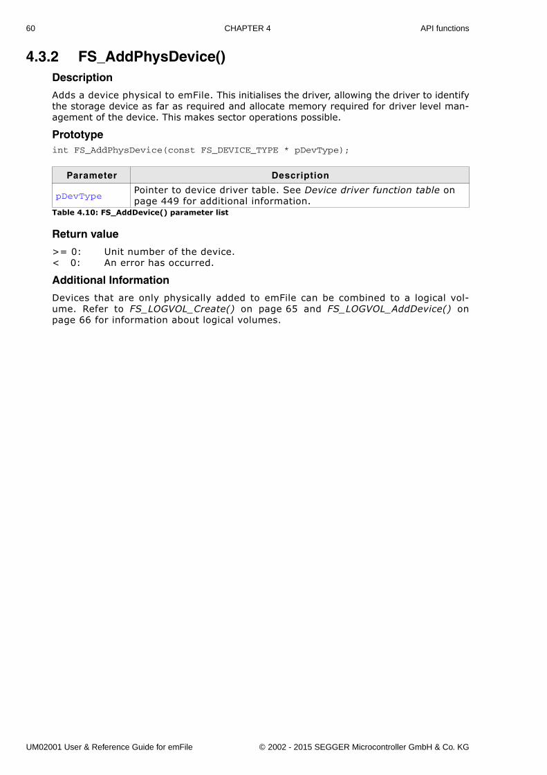
60 CHAPTER 4 API functions
4.3.2 FS_AddPhysDevice()Description
Adds a device physical to emFile. This initialises the driver, allowing the driver to identifythe storage device as far as required and allocate memory required for driver level man-agement of the device. This makes sector operations possible.
Prototypeint FS_AddPhysDevice(const FS_DEVICE_TYPE * pDevType);
Return value
>= 0: Unit number of the device.< 0: An error has occurred.
Additional Information
Devices that are only physically added to emFile can be combined to a logical vol-ume. Refer to FS_LOGVOL_Create() on page 65 and FS_LOGVOL_AddDevice() onpage 66 for information about logical volumes.
Parameter Description
pDevTypePointer to device driver table. See Device driver function table on page 449 for additional information.
Table 4.10: FS_AddDevice() parameter list
UM02001 User & Reference Guide for emFile © 2002 - 2015 SEGGER Microcontroller GmbH & Co. KG
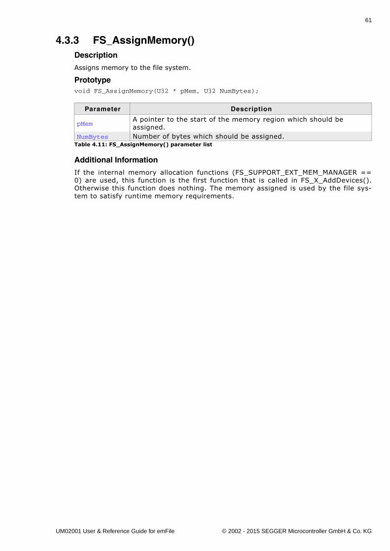
61
4.3.3 FS_AssignMemory()Description
Assigns memory to the file system.
Prototypevoid FS_AssignMemory(U32 * pMem, U32 NumBytes);
Additional Information
If the internal memory allocation functions (FS_SUPPORT_EXT_MEM_MANAGER ==0) are used, this function is the first function that is called in FS_X_AddDevices().Otherwise this function does nothing. The memory assigned is used by the file sys-tem to satisfy runtime memory requirements.
Parameter Description
pMemA pointer to the start of the memory region which should be assigned.
NumBytes Number of bytes which should be assigned.Table 4.11: FS_AssignMemory() parameter list
UM02001 User & Reference Guide for emFile © 2002 - 2015 SEGGER Microcontroller GmbH & Co. KG
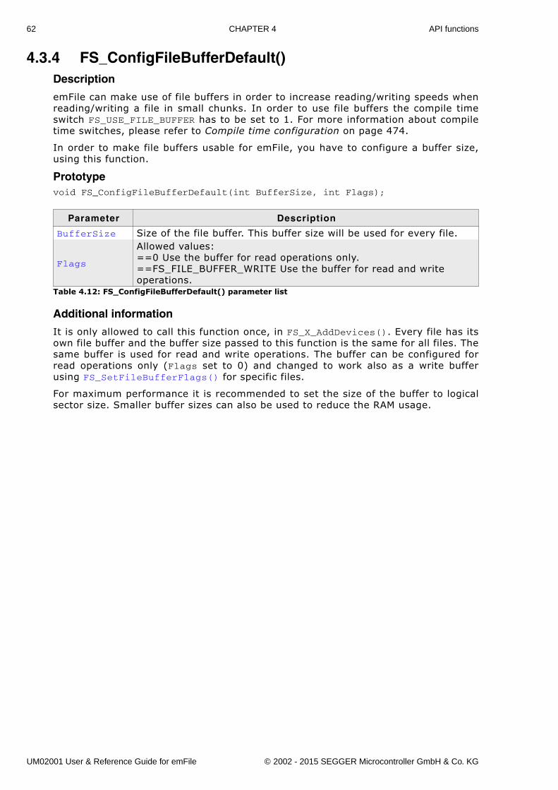
62 CHAPTER 4 API functions
4.3.4 FS_ConfigFileBufferDefault()Description
emFile can make use of file buffers in order to increase reading/writing speeds whenreading/writing a file in small chunks. In order to use file buffers the compile timeswitch FS_USE_FILE_BUFFER has to be set to 1. For more information about compiletime switches, please refer to Compile time configuration on page 474.
In order to make file buffers usable for emFile, you have to configure a buffer size,using this function.
Prototypevoid FS_ConfigFileBufferDefault(int BufferSize, int Flags);
Additional information
It is only allowed to call this function once, in FS_X_AddDevices(). Every file has itsown file buffer and the buffer size passed to this function is the same for all files. Thesame buffer is used for read and write operations. The buffer can be configured forread operations only (Flags set to 0) and changed to work also as a write bufferusing FS_SetFileBufferFlags() for specific files.
For maximum performance it is recommended to set the size of the buffer to logicalsector size. Smaller buffer sizes can also be used to reduce the RAM usage.
Parameter Description
BufferSize Size of the file buffer. This buffer size will be used for every file.
Flags
Allowed values:==0 Use the buffer for read operations only.==FS_FILE_BUFFER_WRITE Use the buffer for read and writeoperations.
Table 4.12: FS_ConfigFileBufferDefault() parameter list
UM02001 User & Reference Guide for emFile © 2002 - 2015 SEGGER Microcontroller GmbH & Co. KG
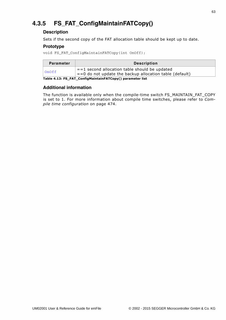
63
4.3.5 FS_FAT_ConfigMaintainFATCopy()Description
Sets if the second copy of the FAT allocation table should be kept up to date.
Prototypevoid FS_FAT_ConfigMaintainFATCopy(int OnOff);
Additional information
The function is available only when the compile-time switch FS_MAINTAIN_FAT_COPYis set to 1. For more information about compile time switches, please refer to Com-pile time configuration on page 474.
Parameter Description
OnOff==1 second allocation table should be updated==0 do not update the backup allocation table (default)
Table 4.13: FS_FAT_ConfigMaintainFATCopy() parameter list
UM02001 User & Reference Guide for emFile © 2002 - 2015 SEGGER Microcontroller GmbH & Co. KG
64 CHAPTER 4 API functions
4.3.6 FS_FAT_ConfigUseFSInfoSector()Description
Sets if the information stored in the FSInfoSector of a FAT32 volume should be eval-uated.
Prototypevoid FS_FAT_ConfigUseFSInfoSector(int OnOff);
Additional information
The FSInfoSector stores the number of free clusters and the position of the next freecluster. The number of free clusters is used by emFile to compute the available freespace on the storage medium on an efficient way. Without this information the avail-able free space must be determined by visiting all FAT entries and counting which ofthem are not allocated. This operation is slow on large storage mediums. Unfortu-nately, the information stored in the FSInfoSector is not 100% reliable. Applicationswhich require very reliable information about the available free space can disable theuse of information from FSInfoSector by calling this function withe the OnOff param-eter set to 0.
To take effect, the function must be called before any FAT32 volume is mounted. Thefunction is available only when the compile-time switch FS_FAT_USE_FSINFO_SECTOR isset to 1. For more information about compile time switches, please refer to Compiletime configuration on page 474.
Parameter Description
OnOff==1 use the information from FSInfoSector (default)==0 ignore FSInfoSector information
Table 4.14: FS_FAT_ConfigUseFSInfoSector() parameter list
UM02001 User & Reference Guide for emFile © 2002 - 2015 SEGGER Microcontroller GmbH & Co. KG
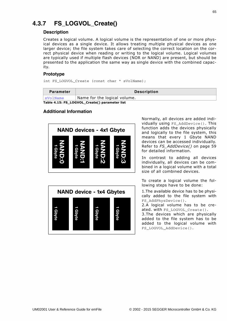
65
4.3.7 FS_LOGVOL_Create()Description
Creates a logical volume. A logical volume is the representation of one or more phys-ical devices as a single device. It allows treating multiple physical devices as onelarger device; the file system takes care of selecting the correct location on the cor-rect physical device when reading or writing to the logical volume. Logical volumesare typically used if multiple flash devices (NOR or NAND) are present, but should bepresented to the application the same way as single device with the combined capac-ity.
Prototypeint FS_LOGVOL_Create (const char * sVolName);
Additional Information
Normally, all devices are added indi-vidually using FS_AddDevice(). Thisfunction adds the devices physicallyand logically to the file system, thismeans that every 1 Gbyte NANDdevices can be accessed individually.Refer to FS_AddDevice() on page 59for detailed information.
In contrast to adding all devicesindividually, all devices can be com-bined in a logical volume with a totalsize of all combined devices.
To create a logical volume the fol-lowing steps have to be done:
1.The available device has to be physi-cally added to the file system withFS_AddPhysDevice().2.A logical volume has to be cre-ated. with FS_LOGVOL_Create(). 3.The devices which are physicallyadded to the file system has to beadded to the logical volume withFS_LOGVOL_AddDevice().
Parameter Description
sVolName Name for the logical volume.Table 4.15: FS_LOGVOL_Create() parameter list
NA
ND
:21 G
byte
NA
ND
:31 G
byte
NA
ND
:01 G
byte
NA
ND
:11 G
byte
NAND devices - 4x1 Gbyte1 G
byte
1 Gbyte
1 Gbyte
1 Gbyte
NAND device - 1x4 Gbytes
UM02001 User & Reference Guide for emFile © 2002 - 2015 SEGGER Microcontroller GmbH & Co. KG
66 CHAPTER 4 API functions
4.3.8 FS_LOGVOL_AddDevice()Description
Adds a device to a logical volume.
Prototypeint FS_LOGVOL_AddDevice(const char * sLogVolName, const FS_DEVICE_TYPE * pDevice, U8 Unit, U32 StartOff,
U32 NumSectors);
Additional information
Only devices with an identical sector size can be combined to a logical volume. Alladditional added devices need to have the same sector size as the first physicaldevice of the logical volume.
Example
void FS_X_AddDevices(void) { void * pRAM; U8 Unit1, Unit2;
// // Add the RAM drives physical to FS // Unit1 = FS_AddPhysDevice(&FS_RAMDISK_Driver); Unit2 = FS_AddPhysDevice(&FS_RAMDISK_Driver); // // Allocate the required memory and configure the RAM drives // pRAM = FS_Alloc(RAMDISK_NUM_SECTORS * RAMDISK_BYTES_PER_SECTOR); FS_RAMDISK_Configure(Unit1, pRAM, RAMDISK_BYTES_PER_SECTOR, RAMDISK_NUM_SECTORS); pRAM = FS_Alloc(RAMDISK_NUM_SECTORS * RAMDISK_BYTES_PER_SECTOR); FS_RAMDISK_Configure(Unit2, pRAM, RAMDISK_BYTES_PER_SECTOR, RAMDISK_NUM_SECTORS); // // Create a logical volume to composite the RAM drives // FS_LOGVOL_Create("ramc"); // // Add the devices // FS_LOGVOL_AddDevice("ramc", &FS_RAMDISK_Driver, Unit1, 0, 0); FS_LOGVOL_AddDevice("ramc", &FS_RAMDISK_Driver, Unit2, 0, 0);
if (FS_IsHLFormatted("ramc") == 0) { FS_Format("ramc", NULL); }}
Parameter Description
sVolName Name of the logical volume.pDevice Pointer to device type that should be added.Unit Number of unit that should be added.StartOff Offset to define the start of sector range that should be used. NumSector Number of sectors that should be used.
Table 4.16: FS_LOGVOL_AddDevice() parameter list
UM02001 User & Reference Guide for emFile © 2002 - 2015 SEGGER Microcontroller GmbH & Co. KG
67
4.3.9 FS_SetFileBufferFlags()Description
Allows to change the file buffer flags for a specific file. This allows the user to havedifferent file buffers (read-only, read/write, etc.) for different files.
Prototypevoid FS_SetFileBufferFlags(FS_FILE * pFile, int Flags);
Additional information
It is only allowed to call this function immediately after opening a file. If read/writeoperations to the file have already been performed, the file has to be closed and re-opened in order to change the file buffer settings. This is necessary to guarantee,that all the file buffer is synchronized before changing the usage flags.
When the buffer is also used for write operations, the data is written to the storagemedium only when the buffer is full or when the data crosses the boundary of a logi-cal sector. This reduces the number of write accesses and can lead to significant per-formance improvements especially when writing a lot of smaller chunks.
Old nameFS_ConfigFileBufferFlags
Example
The following sample program shows how to configure the file buffer for read andwrite operation.
void SampleFileBufferFlags(void) { FS_FILE * pFile;
pFile = FS_FOpen("test.txt", "w"); if (pFile) { // // Set the file buffer for read and write operation. // FS_SetFileBufferFlags(pFile, FS_FILE_BUFFER_WRITE); // // Data is written to file buffer. // FS_Write(pFile, "Test", 4); // // Write the data from file buffer to storage and close the file. // FS_FClose(pFile); }}
Parameter Description
pFile Handle of file which buffer flags shall be changed
Flags
Allowed values:==0 Use the buffer for read operations only.==FS_FILE_BUFFER_WRITE Use the buffer for read and writeoperations.
Table 4.17: FS_SetFileBufferFlags() parameter list
UM02001 User & Reference Guide for emFile © 2002 - 2015 SEGGER Microcontroller GmbH & Co. KG
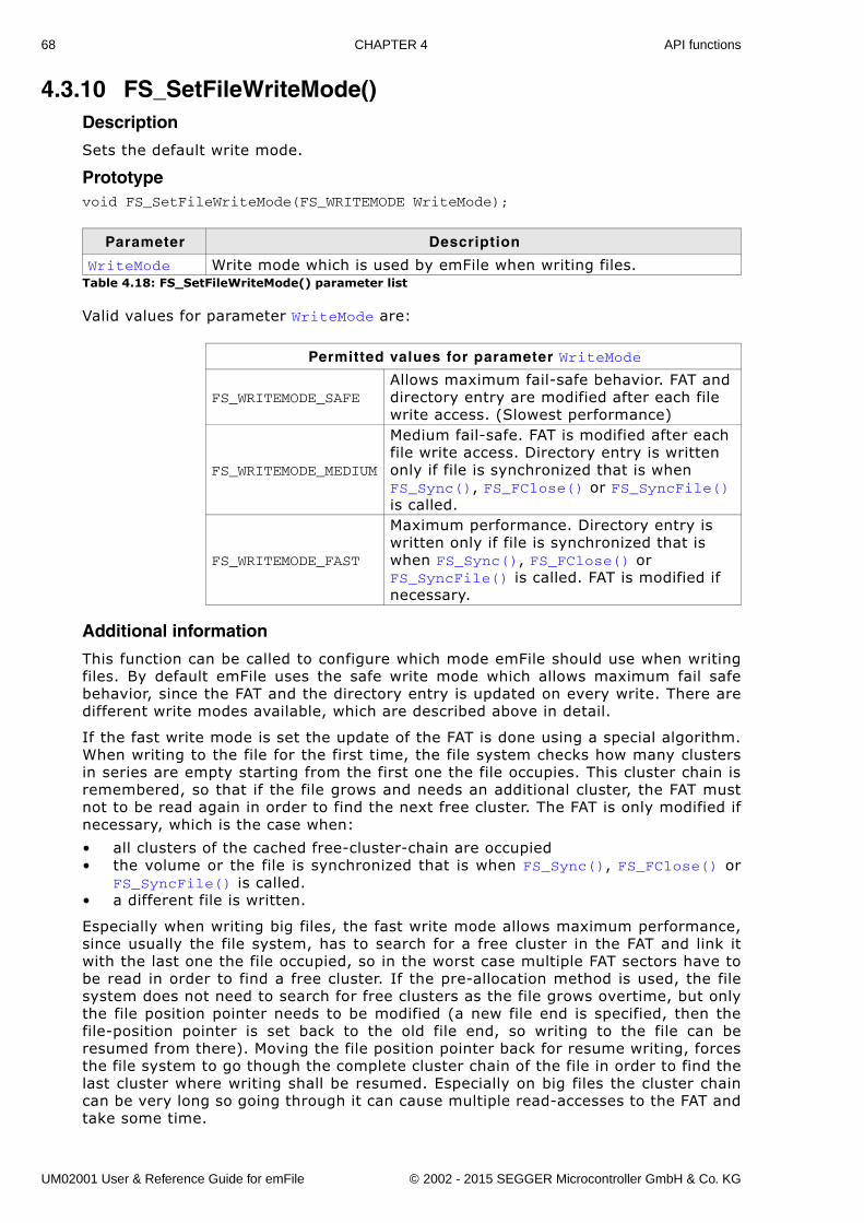
68 CHAPTER 4 API functions
4.3.10 FS_SetFileWriteMode()Description
Sets the default write mode.
Prototypevoid FS_SetFileWriteMode(FS_WRITEMODE WriteMode);
Valid values for parameter WriteMode are:
Additional information
This function can be called to configure which mode emFile should use when writingfiles. By default emFile uses the safe write mode which allows maximum fail safebehavior, since the FAT and the directory entry is updated on every write. There aredifferent write modes available, which are described above in detail.
If the fast write mode is set the update of the FAT is done using a special algorithm.When writing to the file for the first time, the file system checks how many clustersin series are empty starting from the first one the file occupies. This cluster chain isremembered, so that if the file grows and needs an additional cluster, the FAT mustnot to be read again in order to find the next free cluster. The FAT is only modified ifnecessary, which is the case when:
� all clusters of the cached free-cluster-chain are occupied� the volume or the file is synchronized that is when FS_Sync(), FS_FClose() or
FS_SyncFile() is called.� a different file is written.
Especially when writing big files, the fast write mode allows maximum performance,since usually the file system, has to search for a free cluster in the FAT and link itwith the last one the file occupied, so in the worst case multiple FAT sectors have tobe read in order to find a free cluster. If the pre-allocation method is used, the filesystem does not need to search for free clusters as the file grows overtime, but onlythe file position pointer needs to be modified (a new file end is specified, then thefile-position pointer is set back to the old file end, so writing to the file can beresumed from there). Moving the file position pointer back for resume writing, forcesthe file system to go though the complete cluster chain of the file in order to find thelast cluster where writing shall be resumed. Especially on big files the cluster chaincan be very long so going through it can cause multiple read-accesses to the FAT andtake some time.
Parameter Description
WriteMode Write mode which is used by emFile when writing files.Table 4.18: FS_SetFileWriteMode() parameter list
Permitted values for parameter WriteMode
FS_WRITEMODE_SAFEAllows maximum fail-safe behavior. FAT and directory entry are modified after each file write access. (Slowest performance)
FS_WRITEMODE_MEDIUM
Medium fail-safe. FAT is modified after each file write access. Directory entry is written only if file is synchronized that is when FS_Sync(), FS_FClose() or FS_SyncFile() is called.
FS_WRITEMODE_FAST
Maximum performance. Directory entry is written only if file is synchronized that is when FS_Sync(), FS_FClose() or FS_SyncFile() is called. FAT is modified if necessary.
UM02001 User & Reference Guide for emFile © 2002 - 2015 SEGGER Microcontroller GmbH & Co. KG
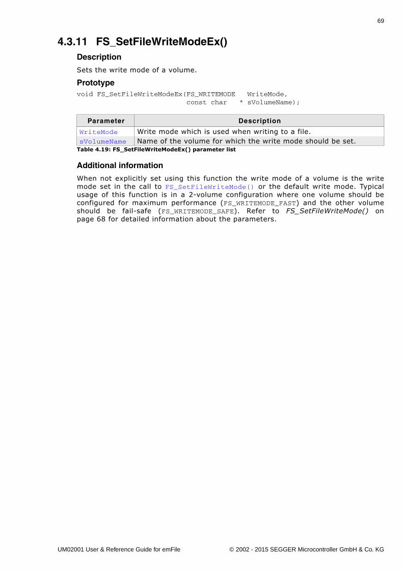
69
4.3.11 FS_SetFileWriteModeEx()Description
Sets the write mode of a volume.
Prototypevoid FS_SetFileWriteModeEx(FS_WRITEMODE WriteMode, const char * sVolumeName);
Additional information
When not explicitly set using this function the write mode of a volume is the writemode set in the call to FS_SetFileWriteMode() or the default write mode. Typicalusage of this function is in a 2-volume configuration where one volume should beconfigured for maximum performance (FS_WRITEMODE_FAST) and the other volumeshould be fail-safe (FS_WRITEMODE_SAFE). Refer to FS_SetFileWriteMode() onpage 68 for detailed information about the parameters.
Parameter Description
WriteMode Write mode which is used when writing to a file.sVolumeName Name of the volume for which the write mode should be set.
Table 4.19: FS_SetFileWriteModeEx() parameter list
UM02001 User & Reference Guide for emFile © 2002 - 2015 SEGGER Microcontroller GmbH & Co. KG
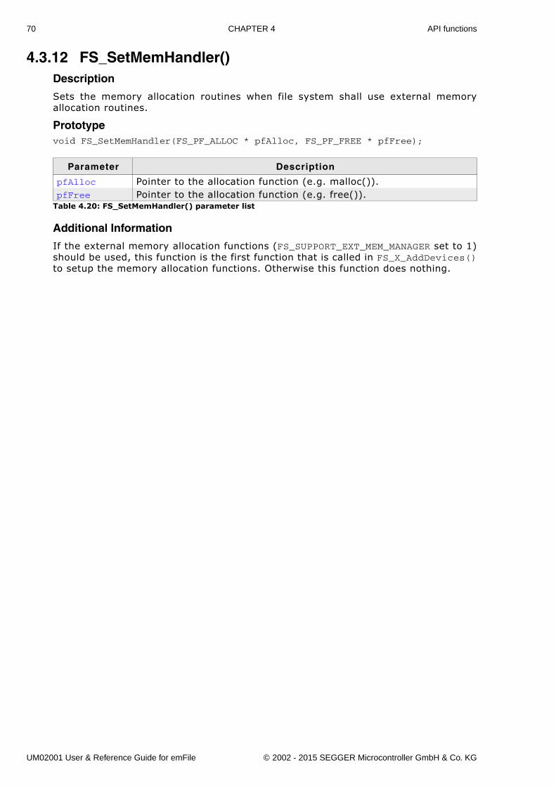
70 CHAPTER 4 API functions
4.3.12 FS_SetMemHandler()Description
Sets the memory allocation routines when file system shall use external memoryallocation routines.
Prototypevoid FS_SetMemHandler(FS_PF_ALLOC * pfAlloc, FS_PF_FREE * pfFree);
Additional Information
If the external memory allocation functions (FS_SUPPORT_EXT_MEM_MANAGER set to 1)should be used, this function is the first function that is called in FS_X_AddDevices()to setup the memory allocation functions. Otherwise this function does nothing.
Parameter Description
pfAlloc Pointer to the allocation function (e.g. malloc()).pfFree Pointer to the allocation function (e.g. free()).
Table 4.20: FS_SetMemHandler() parameter list
UM02001 User & Reference Guide for emFile © 2002 - 2015 SEGGER Microcontroller GmbH & Co. KG
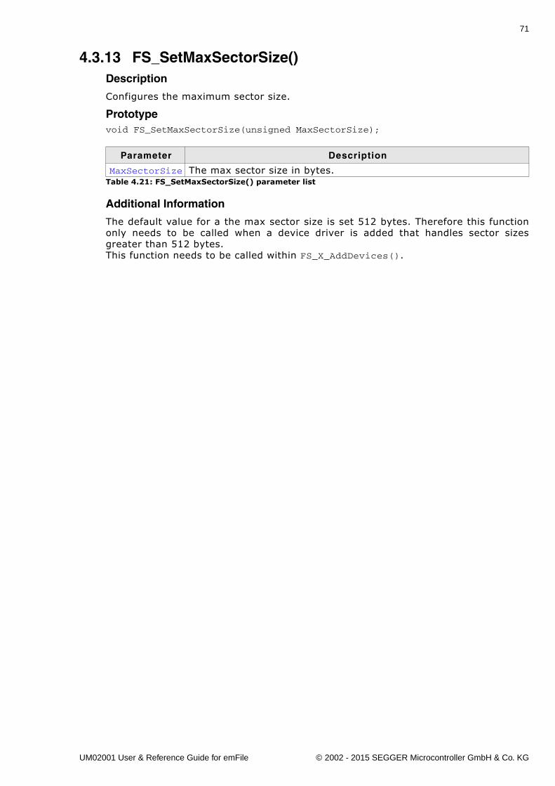
71
4.3.13 FS_SetMaxSectorSize()Description
Configures the maximum sector size.
Prototypevoid FS_SetMaxSectorSize(unsigned MaxSectorSize);
Additional Information
The default value for a the max sector size is set 512 bytes. Therefore this functiononly needs to be called when a device driver is added that handles sector sizesgreater than 512 bytes.This function needs to be called within FS_X_AddDevices().
Parameter Description
MaxSectorSize The max sector size in bytes.Table 4.21: FS_SetMaxSectorSize() parameter list
UM02001 User & Reference Guide for emFile © 2002 - 2015 SEGGER Microcontroller GmbH & Co. KG
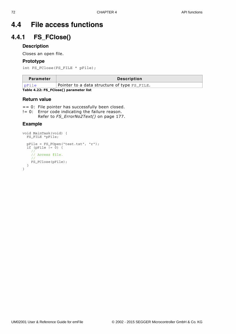
72 CHAPTER 4 API functions
4.4 File access functions
4.4.1 FS_FClose()Description
Closes an open file.
Prototypeint FS_FClose(FS_FILE * pFile);
Return value
== 0: File pointer has successfully been closed.!= 0: Error code indicating the failure reason.
Refer to FS_ErrorNo2Text() on page 177.
Example
void MainTask(void) { FS_FILE *pFile; pFile = FS_FOpen("test.txt", "r"); if (pFile != 0) { // // Access file. // FS_FClose(pFile); }}
Parameter Description
pFile Pointer to a data structure of type FS_FILE.Table 4.22: FS_FClose() parameter list
UM02001 User & Reference Guide for emFile © 2002 - 2015 SEGGER Microcontroller GmbH & Co. KG
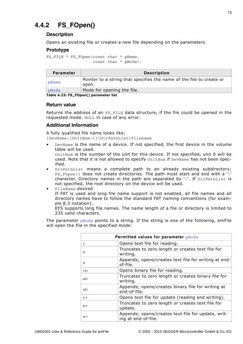
73
4.4.2 FS_FOpen()Description
Opens an existing file or creates a new file depending on the parameters.
PrototypeFS_FILE * FS_FOpen(const char * pName, const char * pMode);
Return value
Returns the address of an FS_FILE data structure, if the file could be opened in therequested mode. NULL in case of any error.
Additional Information
A fully qualified file name looks like:[DevName:[UnitNum:]][DirPathList]Filename
� DevName is the name of a device. If not specified, the first device in the volumetable will be used.UnitNum is the number of the unit for this device. If not specified, unit 0 will beused. Note that it is not allowed to specify UnitNum if DevName has not been spec-ified.
� DirPathList means a complete path to an already existing subdirectory;FS_FOpen() does not create directories. The path must start and end with a '\'character. Directory names in the path are separated by '\'. If DirPathList isnot specified, the root directory on the device will be used.
� FileName desiredIf FAT is used and long file name support is not enabled, all file names and alldirectory names have to follow the standard FAT naming conventions (for exam-ple 8.3 notation).EFS supports long file names. The name length of a file or directory is limited to235 valid characters.
The parameter pMode points to a string. If the string is one of the following, emFilewill open the file in the specified mode:
Parameter Description
pNamePointer to a string that specifies the name of the file to create or open.
pMode Mode for opening the file.Table 4.23: FS_FOpen() parameter list
Permitted values for parameter pMode
r Opens text file for reading.
wTruncates to zero length or creates text file for writing.
aAppends; opens/creates text file for writing at end-of-file.
rb Opens binary file for reading.
wbTruncates to zero length or creates binary file for writing.
abAppends; opens/creates binary file for writing at end-of-file.
r+ Opens text file for update (reading and writing).
w+Truncates to zero length or creates text file for update.
a+Appends; opens/creates text file for update, writ-ing at end-of-file.
UM02001 User & Reference Guide for emFile © 2002 - 2015 SEGGER Microcontroller GmbH & Co. KG
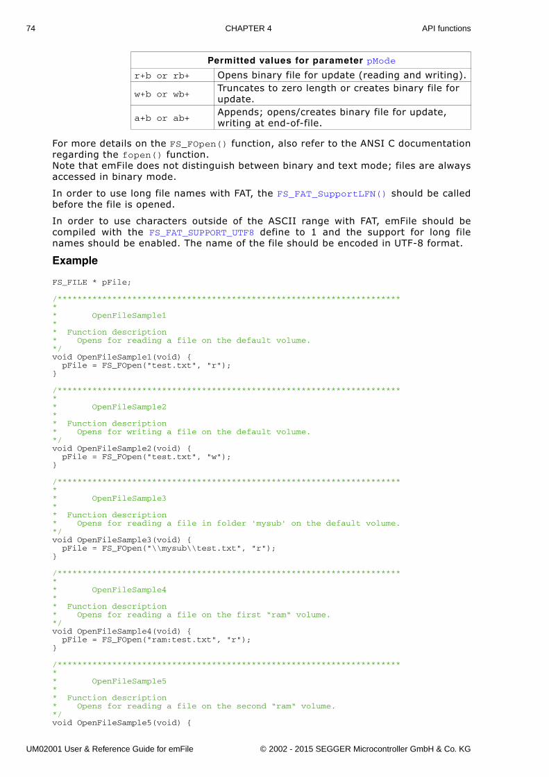
74 CHAPTER 4 API functions
For more details on the FS_FOpen() function, also refer to the ANSI C documentationregarding the fopen() function. Note that emFile does not distinguish between binary and text mode; files are alwaysaccessed in binary mode.
In order to use long file names with FAT, the FS_FAT_SupportLFN() should be calledbefore the file is opened.
In order to use characters outside of the ASCII range with FAT, emFile should becompiled with the FS_FAT_SUPPORT_UTF8 define to 1 and the support for long filenames should be enabled. The name of the file should be encoded in UTF-8 format.
Example
FS_FILE * pFile;
/*********************************************************************** OpenFileSample1** Function description* Opens for reading a file on the default volume.*/void OpenFileSample1(void) { pFile = FS_FOpen("test.txt", "r");}
/*********************************************************************** OpenFileSample2** Function description* Opens for writing a file on the default volume.*/void OpenFileSample2(void) { pFile = FS_FOpen("test.txt", "w");}
/*********************************************************************** OpenFileSample3** Function description* Opens for reading a file in folder 'mysub' on the default volume.*/void OpenFileSample3(void) { pFile = FS_FOpen("\\mysub\\test.txt", "r");}
/*********************************************************************** OpenFileSample4** Function description* Opens for reading a file on the first “ram“ volume.*/void OpenFileSample4(void) { pFile = FS_FOpen("ram:test.txt", "r");}
/*********************************************************************** OpenFileSample5** Function description* Opens for reading a file on the second “ram“ volume.*/void OpenFileSample5(void) {
r+b or rb+ Opens binary file for update (reading and writing).
w+b or wb+Truncates to zero length or creates binary file for update.
a+b or ab+Appends; opens/creates binary file for update, writing at end-of-file.
Permitted values for parameter pMode
UM02001 User & Reference Guide for emFile © 2002 - 2015 SEGGER Microcontroller GmbH & Co. KG
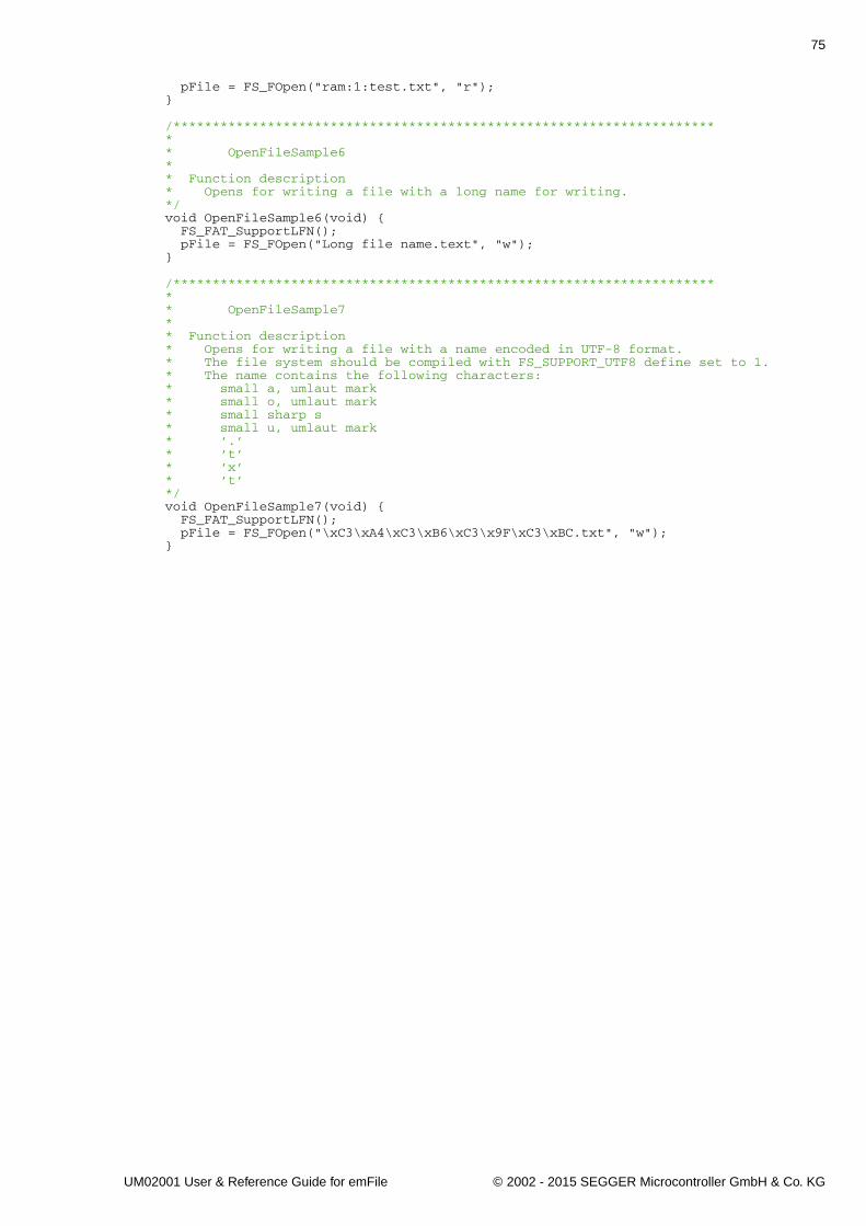
75
pFile = FS_FOpen("ram:1:test.txt", "r");}
/*********************************************************************** OpenFileSample6** Function description* Opens for writing a file with a long name for writing.*/void OpenFileSample6(void) { FS_FAT_SupportLFN(); pFile = FS_FOpen("Long file name.text", "w");}
/*********************************************************************** OpenFileSample7** Function description* Opens for writing a file with a name encoded in UTF-8 format.* The file system should be compiled with FS_SUPPORT_UTF8 define set to 1.* The name contains the following characters:* small a, umlaut mark* small o, umlaut mark* small sharp s* small u, umlaut mark* ’.’* ’t’* ’x’* ’t’*/void OpenFileSample7(void) { FS_FAT_SupportLFN(); pFile = FS_FOpen("\xC3\xA4\xC3\xB6\xC3\x9F\xC3\xBC.txt", "w");}
UM02001 User & Reference Guide for emFile © 2002 - 2015 SEGGER Microcontroller GmbH & Co. KG
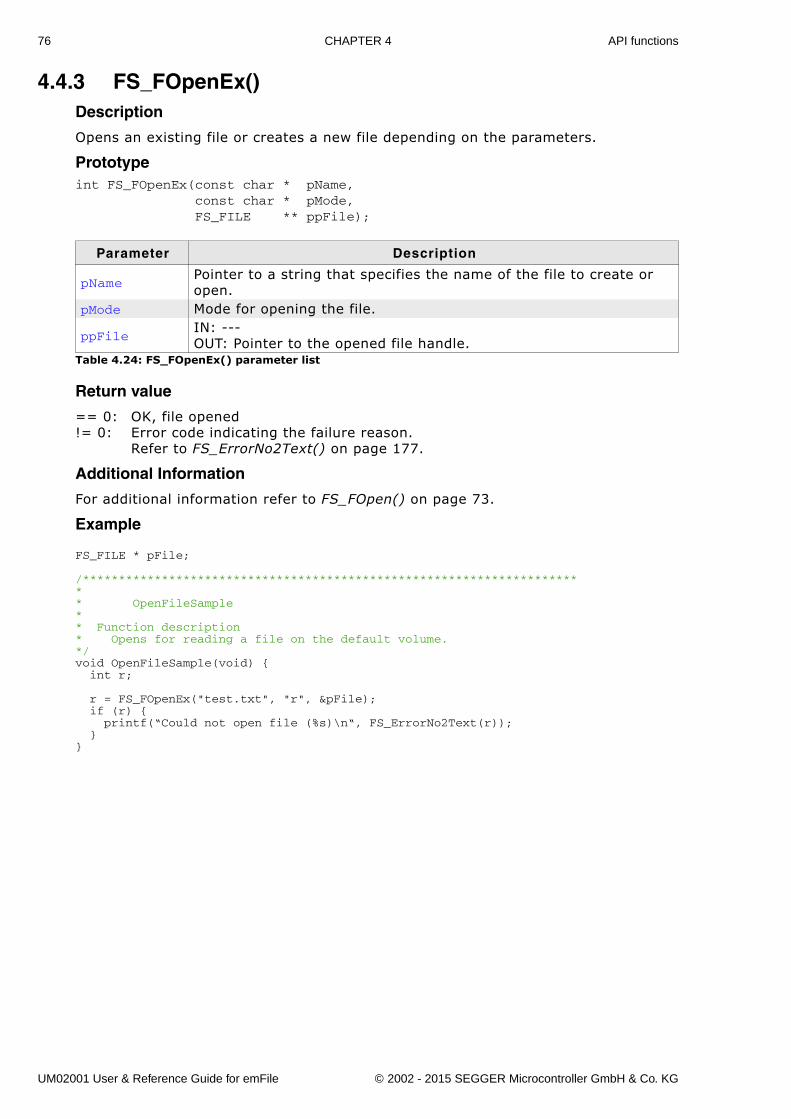
76 CHAPTER 4 API functions
4.4.3 FS_FOpenEx()Description
Opens an existing file or creates a new file depending on the parameters.
Prototypeint FS_FOpenEx(const char * pName, const char * pMode, FS_FILE ** ppFile);
Return value
== 0: OK, file opened!= 0: Error code indicating the failure reason.
Refer to FS_ErrorNo2Text() on page 177.
Additional Information
For additional information refer to FS_FOpen() on page 73.
Example
FS_FILE * pFile;
/*********************************************************************** OpenFileSample** Function description* Opens for reading a file on the default volume.*/void OpenFileSample(void) { int r;
r = FS_FOpenEx("test.txt", "r", &pFile); if (r) { printf(“Could not open file (%s)\n“, FS_ErrorNo2Text(r)); }}
Parameter Description
pNamePointer to a string that specifies the name of the file to create or open.
pMode Mode for opening the file.
ppFileIN: ---OUT: Pointer to the opened file handle.
Table 4.24: FS_FOpenEx() parameter list
UM02001 User & Reference Guide for emFile © 2002 - 2015 SEGGER Microcontroller GmbH & Co. KG
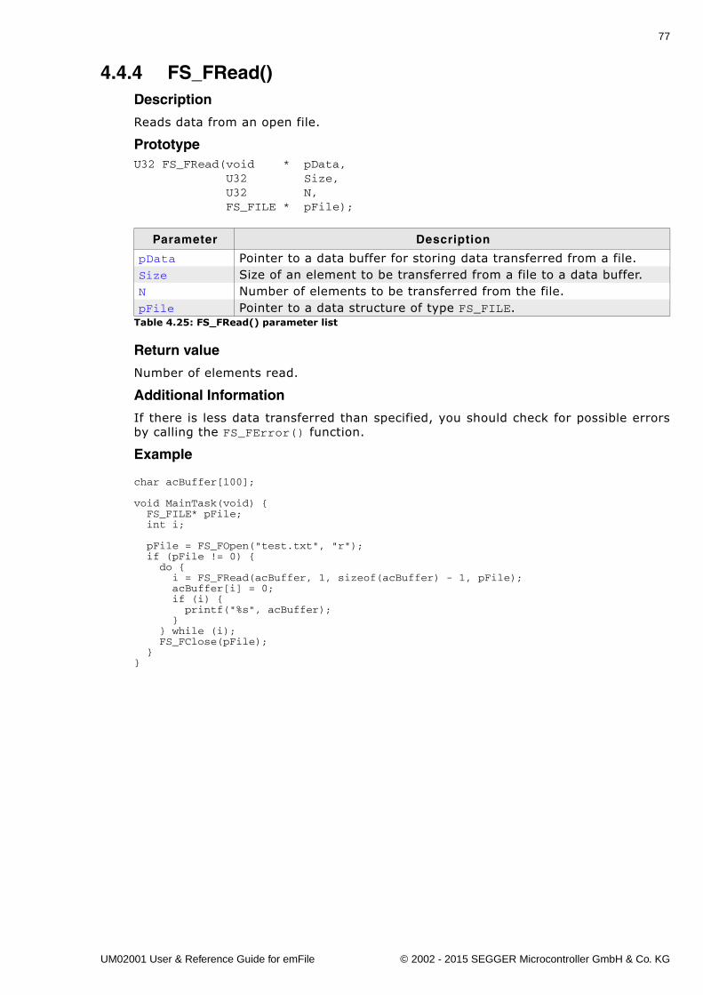
77
4.4.4 FS_FRead()Description
Reads data from an open file.
PrototypeU32 FS_FRead(void * pData, U32 Size, U32 N, FS_FILE * pFile);
Return value
Number of elements read.
Additional Information
If there is less data transferred than specified, you should check for possible errorsby calling the FS_FError() function.
Example
char acBuffer[100];
void MainTask(void) { FS_FILE* pFile; int i; pFile = FS_FOpen("test.txt", "r"); if (pFile != 0) { do { i = FS_FRead(acBuffer, 1, sizeof(acBuffer) - 1, pFile); acBuffer[i] = 0; if (i) { printf("%s", acBuffer); } } while (i); FS_FClose(pFile); }}
Parameter Description
pData Pointer to a data buffer for storing data transferred from a file.Size Size of an element to be transferred from a file to a data buffer.N Number of elements to be transferred from the file.pFile Pointer to a data structure of type FS_FILE.
Table 4.25: FS_FRead() parameter list
UM02001 User & Reference Guide for emFile © 2002 - 2015 SEGGER Microcontroller GmbH & Co. KG
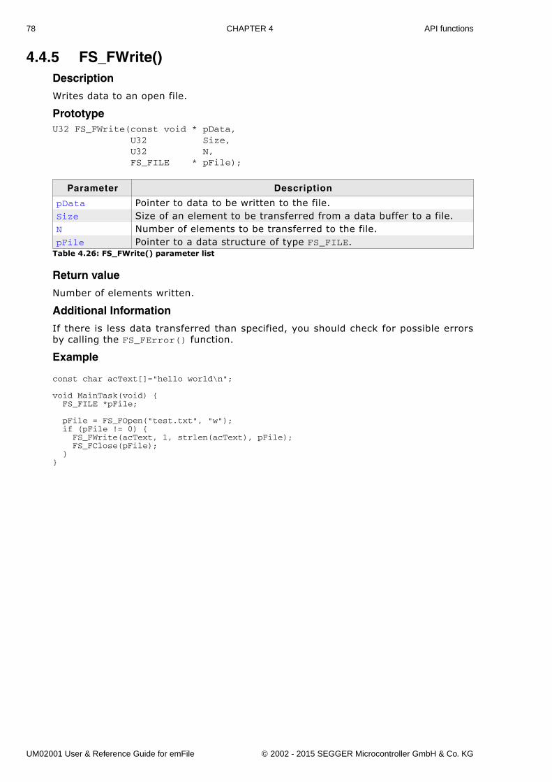
78 CHAPTER 4 API functions
4.4.5 FS_FWrite()Description
Writes data to an open file.
PrototypeU32 FS_FWrite(const void * pData, U32 Size, U32 N, FS_FILE * pFile);
Return value
Number of elements written.
Additional Information
If there is less data transferred than specified, you should check for possible errorsby calling the FS_FError() function.
Example
const char acText[]="hello world\n";
void MainTask(void) { FS_FILE *pFile;
pFile = FS_FOpen("test.txt", "w"); if (pFile != 0) { FS_FWrite(acText, 1, strlen(acText), pFile); FS_FClose(pFile); }}
Parameter Description
pData Pointer to data to be written to the file.Size Size of an element to be transferred from a data buffer to a file.N Number of elements to be transferred to the file.pFile Pointer to a data structure of type FS_FILE.
Table 4.26: FS_FWrite() parameter list
UM02001 User & Reference Guide for emFile © 2002 - 2015 SEGGER Microcontroller GmbH & Co. KG
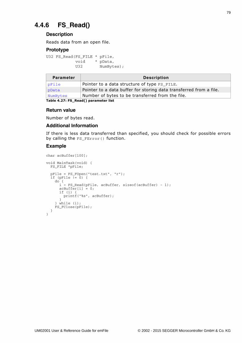
79
4.4.6 FS_Read()Description
Reads data from an open file.
PrototypeU32 FS_Read(FS_FILE * pFile, void * pData, U32 NumBytes);
Return value
Number of bytes read.
Additional Information
If there is less data transferred than specified, you should check for possible errorsby calling the FS_FError() function.
Example
char acBuffer[100];
void MainTask(void) { FS_FILE *pFile; pFile = FS_FOpen("test.txt", "r"); if (pFile != 0) { do { i = FS_Read(pFile, acBuffer, sizeof(acBuffer) - 1); acBuffer[i] = 0; if (i) { printf("%s", acBuffer); } } while (i); FS_FClose(pFile); }}
Parameter Description
pFile Pointer to a data structure of type FS_FILE.pData Pointer to a data buffer for storing data transferred from a file.NumBytes Number of bytes to be transferred from the file.
Table 4.27: FS_Read() parameter list
UM02001 User & Reference Guide for emFile © 2002 - 2015 SEGGER Microcontroller GmbH & Co. KG
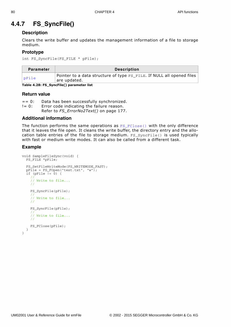
80 CHAPTER 4 API functions
4.4.7 FS_SyncFile()Description
Clears the write buffer and updates the management information of a file to storagemedium.
Prototypeint FS_SyncFile(FS_FILE * pFile);
Return value
== 0: Data has been successfully synchronized.!= 0: Error code indicating the failure reason.
Refer to FS_ErrorNo2Text() on page 177.
Additional information
The function performs the same operations as FS_FClose() with the only differencethat it leaves the file open. It cleans the write buffer, the directory entry and the allo-cation table entries of the file to storage medium. FS_SyncFile() is used typicallywith fast or medium write modes. It can also be called from a different task.
Example
void SampleFileSync(void) { FS_FILE *pFile; FS_SetFileWriteMode(FS_WRITEMODE_FAST); pFile = FS_FOpen("test.txt", "w"); if (pFile != 0) { // // Write to file... // FS_SyncFile(pFile); // // Write to file... // FS_SyncFile(pFile); // // Write to file... // FS_FClose(pFile); }}
Parameter Description
pFilePointer to a data structure of type FS_FILE. If NULL all opened files are updated.
Table 4.28: FS_SyncFile() parameter list
UM02001 User & Reference Guide for emFile © 2002 - 2015 SEGGER Microcontroller GmbH & Co. KG
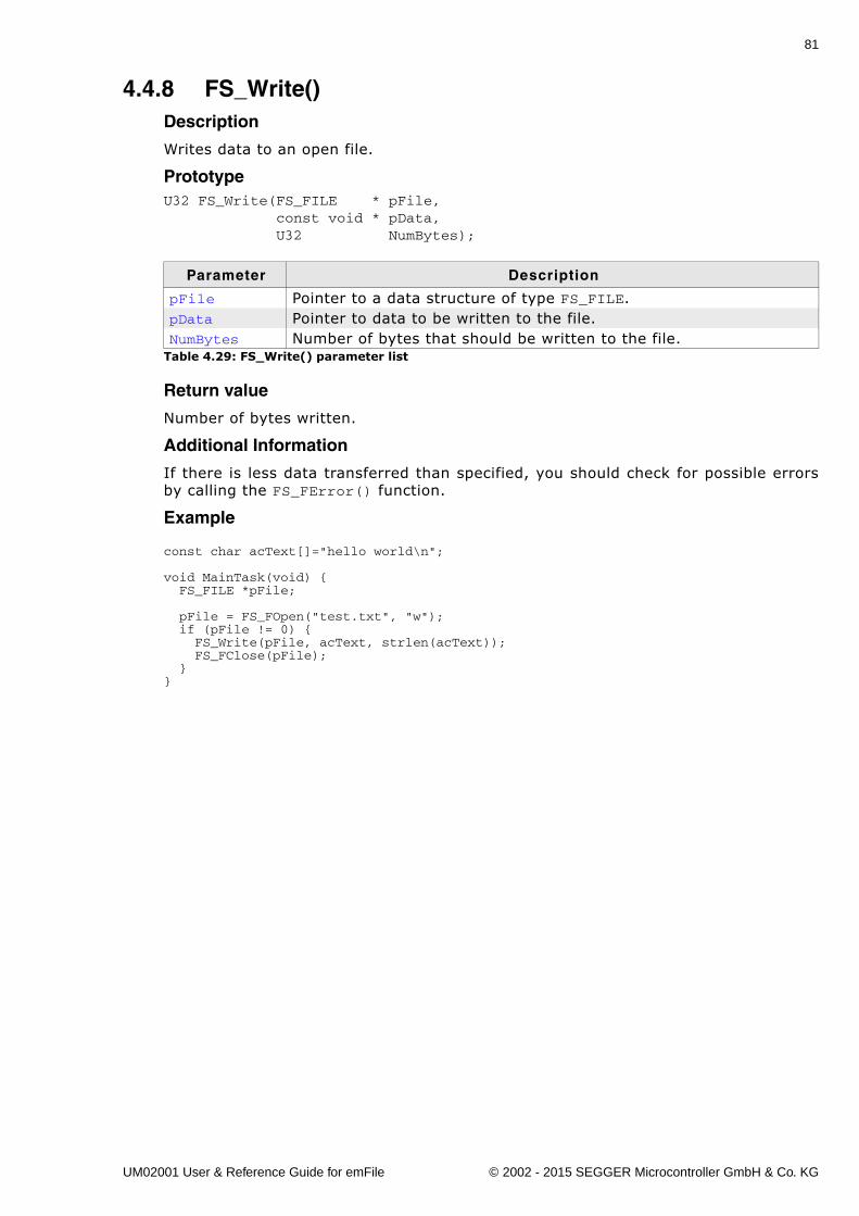
81
4.4.8 FS_Write()Description
Writes data to an open file.
PrototypeU32 FS_Write(FS_FILE * pFile, const void * pData, U32 NumBytes);
Return value
Number of bytes written.
Additional Information
If there is less data transferred than specified, you should check for possible errorsby calling the FS_FError() function.
Example
const char acText[]="hello world\n";
void MainTask(void) { FS_FILE *pFile; pFile = FS_FOpen("test.txt", "w"); if (pFile != 0) { FS_Write(pFile, acText, strlen(acText)); FS_FClose(pFile); }}
Parameter Description
pFile Pointer to a data structure of type FS_FILE.pData Pointer to data to be written to the file.NumBytes Number of bytes that should be written to the file.
Table 4.29: FS_Write() parameter list
UM02001 User & Reference Guide for emFile © 2002 - 2015 SEGGER Microcontroller GmbH & Co. KG
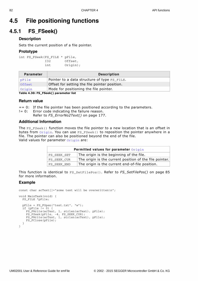
82 CHAPTER 4 API functions
4.5 File positioning functions
4.5.1 FS_FSeek()Description
Sets the current position of a file pointer.
Prototypeint FS_FSeek(FS_FILE * pFile, I32 Offset, int Origin);
Return value
== 0: If the file pointer has been positioned according to the parameters.!= 0: Error code indicating the failure reason.
Refer to FS_ErrorNo2Text() on page 177.
Additional Information
The FS_FSeek() function moves the file pointer to a new location that is an offset inbytes from Origin. You can use FS_FSeek() to reposition the pointer anywhere in afile. The pointer can also be positioned beyond the end of the file. Valid values for parameter Origin are:
This function is identical to FS_SetFilePos(). Refer to FS_SetFilePos() on page 85for more information.
Example
const char acText[]="some text will be overwritten\n";
void MainTask(void) { FS_FILE *pFile; pFile = FS_FOpen("test.txt", "w"); if (pFile != 0) { FS_FWrite(acText, 1, strlen(acText), pFile); FS_FSeek(pFile, -4, FS_SEEK_CUR); FS_FWrite(acText, 1, strlen(acText), pFile); FS_FClose(pFile); }}
Parameter Description
pFile Pointer to a data structure of type FS_FILE.Offset Offset for setting the file pointer position.Origin Mode for positioning the file pointer.
Table 4.30: FS_FSeek() parameter list
Permitted values for parameter Origin
FS_SEEK_SET The origin is the beginning of the file.FS_SEEK_CUR The origin is the current position of the file pointer.FS_SEEK_END The origin is the current end-of-file position.
UM02001 User & Reference Guide for emFile © 2002 - 2015 SEGGER Microcontroller GmbH & Co. KG
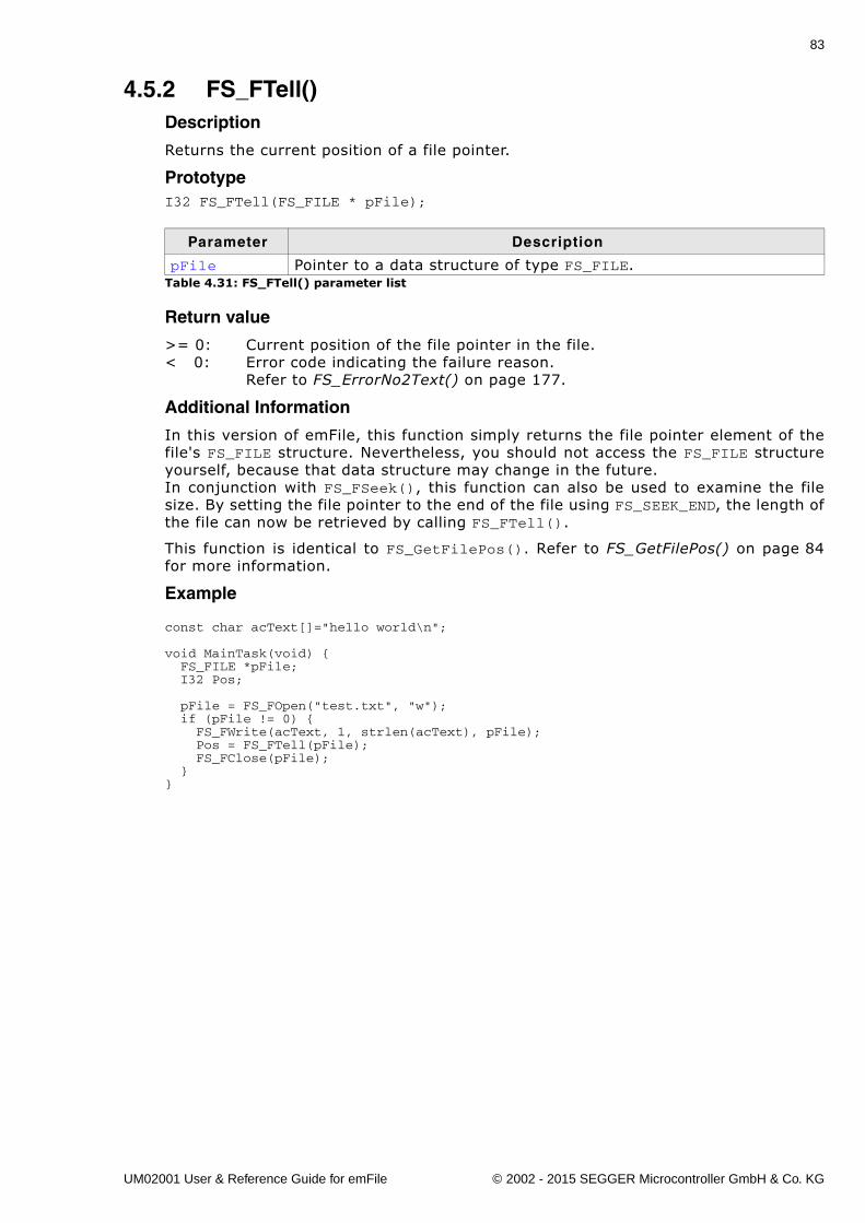
83
4.5.2 FS_FTell()Description
Returns the current position of a file pointer.
PrototypeI32 FS_FTell(FS_FILE * pFile);
Return value
>= 0: Current position of the file pointer in the file.< 0: Error code indicating the failure reason.
Refer to FS_ErrorNo2Text() on page 177.
Additional Information
In this version of emFile, this function simply returns the file pointer element of thefile's FS_FILE structure. Nevertheless, you should not access the FS_FILE structureyourself, because that data structure may change in the future.In conjunction with FS_FSeek(), this function can also be used to examine the filesize. By setting the file pointer to the end of the file using FS_SEEK_END, the length ofthe file can now be retrieved by calling FS_FTell().
This function is identical to FS_GetFilePos(). Refer to FS_GetFilePos() on page 84for more information.
Example
const char acText[]="hello world\n";
void MainTask(void) { FS_FILE *pFile; I32 Pos;
pFile = FS_FOpen("test.txt", "w"); if (pFile != 0) { FS_FWrite(acText, 1, strlen(acText), pFile); Pos = FS_FTell(pFile); FS_FClose(pFile); }}
Parameter Description
pFile Pointer to a data structure of type FS_FILE.Table 4.31: FS_FTell() parameter list
UM02001 User & Reference Guide for emFile © 2002 - 2015 SEGGER Microcontroller GmbH & Co. KG
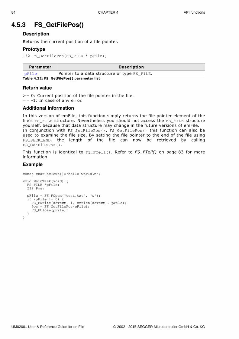
84 CHAPTER 4 API functions
4.5.3 FS_GetFilePos()Description
Returns the current position of a file pointer.
PrototypeI32 FS_GetFilePos(FS_FILE * pFile);
Return value
>= 0: Current position of the file pointer in the file.== -1: In case of any error.
Additional Information
In this version of emFile, this function simply returns the file pointer element of thefile's FS_FILE structure. Nevertheless you should not access the FS_FILE structureyourself, because that data structure may change in the future versions of emFile.In conjunction with FS_SetFilePos(), FS_GetFilePos() this function can also beused to examine the file size. By setting the file pointer to the end of the file usingFS_SEEK_END, the length of the file can now be retrieved by callingFS_GetFilePos().
This function is identical to FS_FTell(). Refer to FS_FTell() on page 83 for moreinformation.
Example
const char acText[]="hello world\n";
void MainTask(void) { FS_FILE *pFile; I32 Pos; pFile = FS_FOpen("test.txt", "w"); if (pFile != 0) { FS_FWrite(acText, 1, strlen(acText), pFile); Pos = FS_GetFilePos(pFile); FS_FClose(pFile); }}
Parameter Description
pFile Pointer to a data structure of type FS_FILE.Table 4.32: FS_GetFilePos() parameter list
UM02001 User & Reference Guide for emFile © 2002 - 2015 SEGGER Microcontroller GmbH & Co. KG
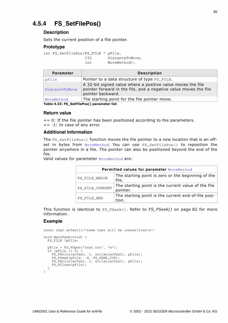
85
4.5.4 FS_SetFilePos()Description
Sets the current position of a file pointer.
Prototypeint FS_SetFilePos(FS_FILE * pFile, I32 DistanceToMove, int MoveMethod);
Return value
== 0: If the file pointer has been positioned according to the parameters.== -1: In case of any error.
Additional Information
The FS_SetFilePos() function moves the file pointer to a new location that is an off-set in bytes from MoveMethod. You can use FS_SetFilePos() to reposition thepointer anywhere in a file. The pointer can also be positioned beyond the end of thefile.Valid values for parameter MoveMethod are:
This function is identical to FS_FSeek(). Refer to FS_FSeek() on page 82 for moreinformation.
Example
const char acText[]="some text will be overwritten\n";
void MainTask(void) { FS_FILE *pFile; pFile = FS_FOpen("test.txt", "w"); if (pFile != 0) { FS_FWrite(acText, 1, strlen(acText), pFile); FS_FSeek(pFile, -4, FS_SEEK_CUR); FS_FWrite(acText, 1, strlen(acText), pFile); FS_FClose(pFile); }}
Parameter Description
pFile Pointer to a data structure of type FS_FILE.
DistanceToMoveA 32-bit signed value where a positive value moves the file pointer forward in the file, and a negative value moves the file pointer backward.
MoveMethod The starting point for the file pointer move.Table 4.33: FS_SetFilePos() parameter list
Permitted values for parameter MoveMethod
FS_FILE_BEGINThe starting point is zero or the beginning of the file.
FS_FILE_CURRENTThe starting point is the current value of the file pointer.
FS_FILE_ENDThe starting point is the current end-of-file posi-tion.
UM02001 User & Reference Guide for emFile © 2002 - 2015 SEGGER Microcontroller GmbH & Co. KG
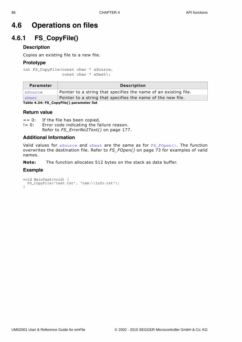
86 CHAPTER 4 API functions
4.6 Operations on files
4.6.1 FS_CopyFile()Description
Copies an existing file to a new file.
Prototypeint FS_CopyFile(const char * sSource, const char * sDest);
Return value
== 0: If the file has been copied.!= 0: Error code indicating the failure reason.
Refer to FS_ErrorNo2Text() on page 177.
Additional Information
Valid values for sSource and sDest are the same as for FS_FOpen(). The functionoverwrites the destination file. Refer to FS_FOpen() on page 73 for examples of validnames.
Note: The function allocates 512 bytes on the stack as data buffer.
Example
void MainTask(void) { FS_CopyFile("test.txt", "ram:\\info.txt");}
Parameter Description
sSource Pointer to a string that specifies the name of an existing file.sDest Pointer to a string that specifies the name of the new file.
Table 4.34: FS_CopyFile() parameter list
UM02001 User & Reference Guide for emFile © 2002 - 2015 SEGGER Microcontroller GmbH & Co. KG
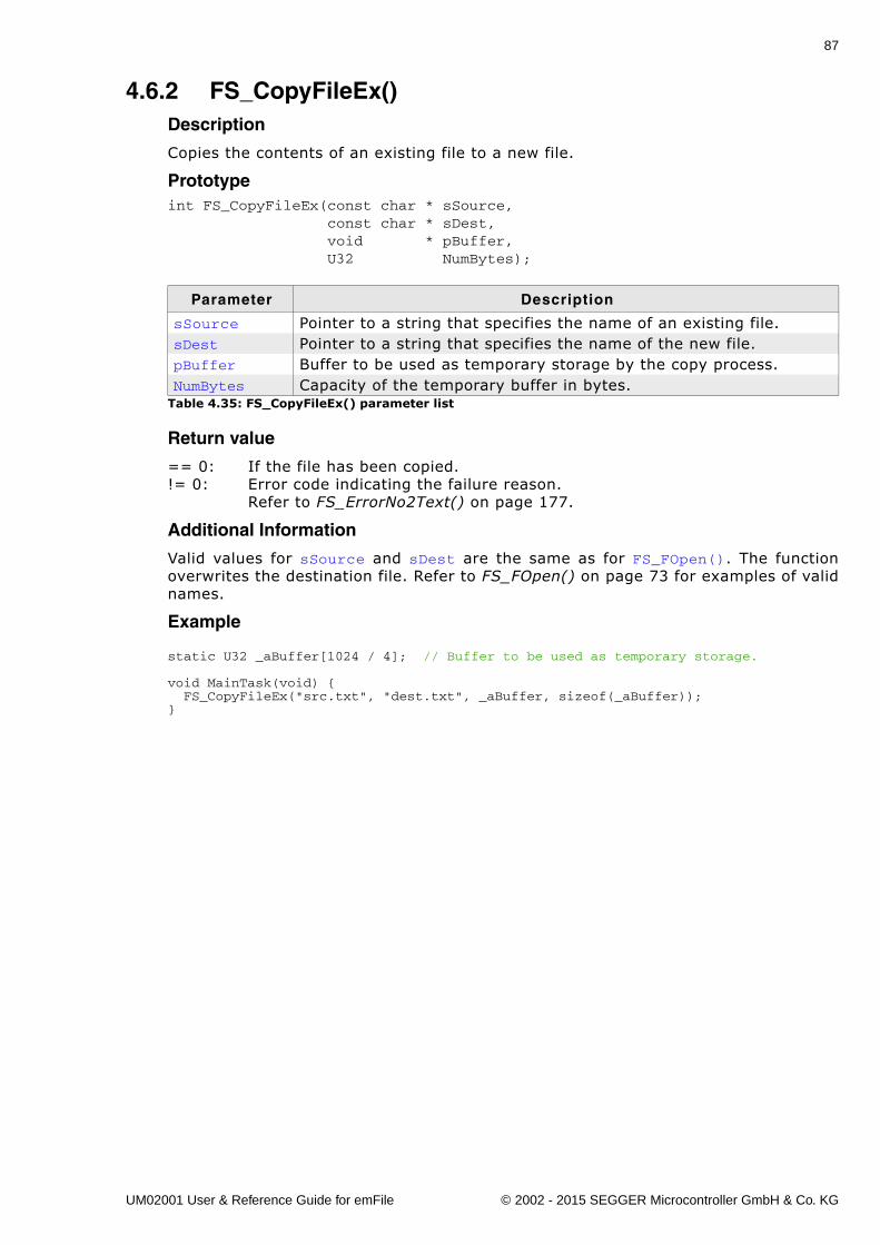
87
4.6.2 FS_CopyFileEx()Description
Copies the contents of an existing file to a new file.
Prototypeint FS_CopyFileEx(const char * sSource, const char * sDest, void * pBuffer, U32 NumBytes);
Return value
== 0: If the file has been copied.!= 0: Error code indicating the failure reason.
Refer to FS_ErrorNo2Text() on page 177.
Additional Information
Valid values for sSource and sDest are the same as for FS_FOpen(). The functionoverwrites the destination file. Refer to FS_FOpen() on page 73 for examples of validnames.
Example
static U32 _aBuffer[1024 / 4]; // Buffer to be used as temporary storage.
void MainTask(void) { FS_CopyFileEx("src.txt", "dest.txt", _aBuffer, sizeof(_aBuffer));}
Parameter Description
sSource Pointer to a string that specifies the name of an existing file.sDest Pointer to a string that specifies the name of the new file.pBuffer Buffer to be used as temporary storage by the copy process.NumBytes Capacity of the temporary buffer in bytes.
Table 4.35: FS_CopyFileEx() parameter list
UM02001 User & Reference Guide for emFile © 2002 - 2015 SEGGER Microcontroller GmbH & Co. KG
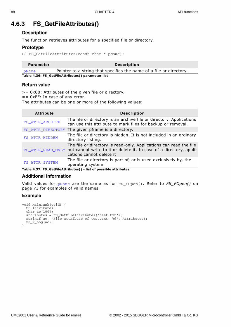
88 CHAPTER 4 API functions
4.6.3 FS_GetFileAttributes()Description
The function retrieves attributes for a specified file or directory.
PrototypeU8 FS_GetFileAttributes(const char * pName);
Return value
>= 0x00: Attributes of the given file or directory.== 0xFF: In case of any error.The attributes can be one or more of the following values:
Additional Information
Valid values for pName are the same as for FS_FOpen(). Refer to FS_FOpen() onpage 73 for examples of valid names.
Example
void MainTask(void) { U8 Attributes; char ac[100]; Attributes = FS_GetFileAttributes("test.txt"); sprintf(ac, "File attribute of test.txt: %d", Attributes); FS_X_Log(ac);}
Parameter Description
pName Pointer to a string that specifies the name of a file or directory.Table 4.36: FS_GetFileAttributes() parameter list
Attribute Description
FS_ATTR_ARCHIVEThe file or directory is an archive file or directory. Applications can use this attribute to mark files for backup or removal.
FS_ATTR_DIRECTORY The given pName is a directory.
FS_ATTR_HIDDENThe file or directory is hidden. It is not included in an ordinary directory listing.
FS_ATTR_READ_ONLYThe file or directory is read-only. Applications can read the file but cannot write to it or delete it. In case of a directory, appli-cations cannot delete it
FS_ATTR_SYSTEMThe file or directory is part of, or is used exclusively by, the operating system.
Table 4.37: FS_GetFileAttributes() - list of possible attributes
UM02001 User & Reference Guide for emFile © 2002 - 2015 SEGGER Microcontroller GmbH & Co. KG
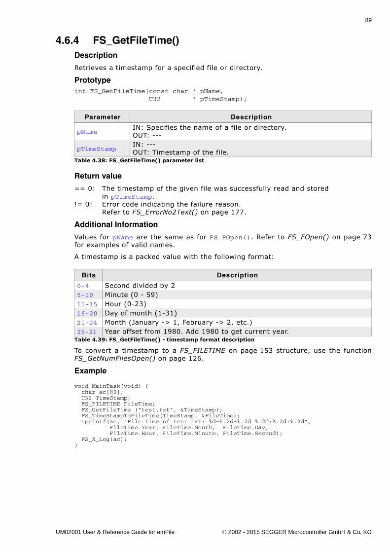
89
4.6.4 FS_GetFileTime()Description
Retrieves a timestamp for a specified file or directory.
Prototypeint FS_GetFileTime(const char * pName, U32 * pTimeStamp);
Return value
== 0: The timestamp of the given file was successfully read and stored in pTimeStamp.
!= 0: Error code indicating the failure reason.Refer to FS_ErrorNo2Text() on page 177.
Additional Information
Values for pName are the same as for FS_FOpen(). Refer to FS_FOpen() on page 73for examples of valid names.
A timestamp is a packed value with the following format:
To convert a timestamp to a FS_FILETIME on page 153 structure, use the functionFS_GetNumFilesOpen() on page 126.
Example
void MainTask(void) { char ac[80]; U32 TimeStamp; FS_FILETIME FileTime; FS_GetFileTime ("test.txt", &TimeStamp); FS_TimeStampToFileTime(TimeStamp, &FileTime); sprintf(ac, "File time of test.txt: %d-%.2d-%.2d %.2d:%.2d:%.2d", FileTime.Year, FileTime.Month, FileTime.Day, FileTime.Hour, FileTime.Minute, FileTime.Second); FS_X_Log(ac);}
Parameter Description
pNameIN: Specifies the name of a file or directory.OUT: ---
pTimeStampIN: ---OUT: Timestamp of the file.
Table 4.38: FS_GetFileTime() parameter list
Bits Description
0-4 Second divided by 25-10 Minute (0 - 59)11-15 Hour (0-23)16-20 Day of month (1-31)21-24 Month (January -> 1, February -> 2, etc.)25-31 Year offset from 1980. Add 1980 to get current year.
Table 4.39: FS_GetFileTime() - timestamp format description
UM02001 User & Reference Guide for emFile © 2002 - 2015 SEGGER Microcontroller GmbH & Co. KG
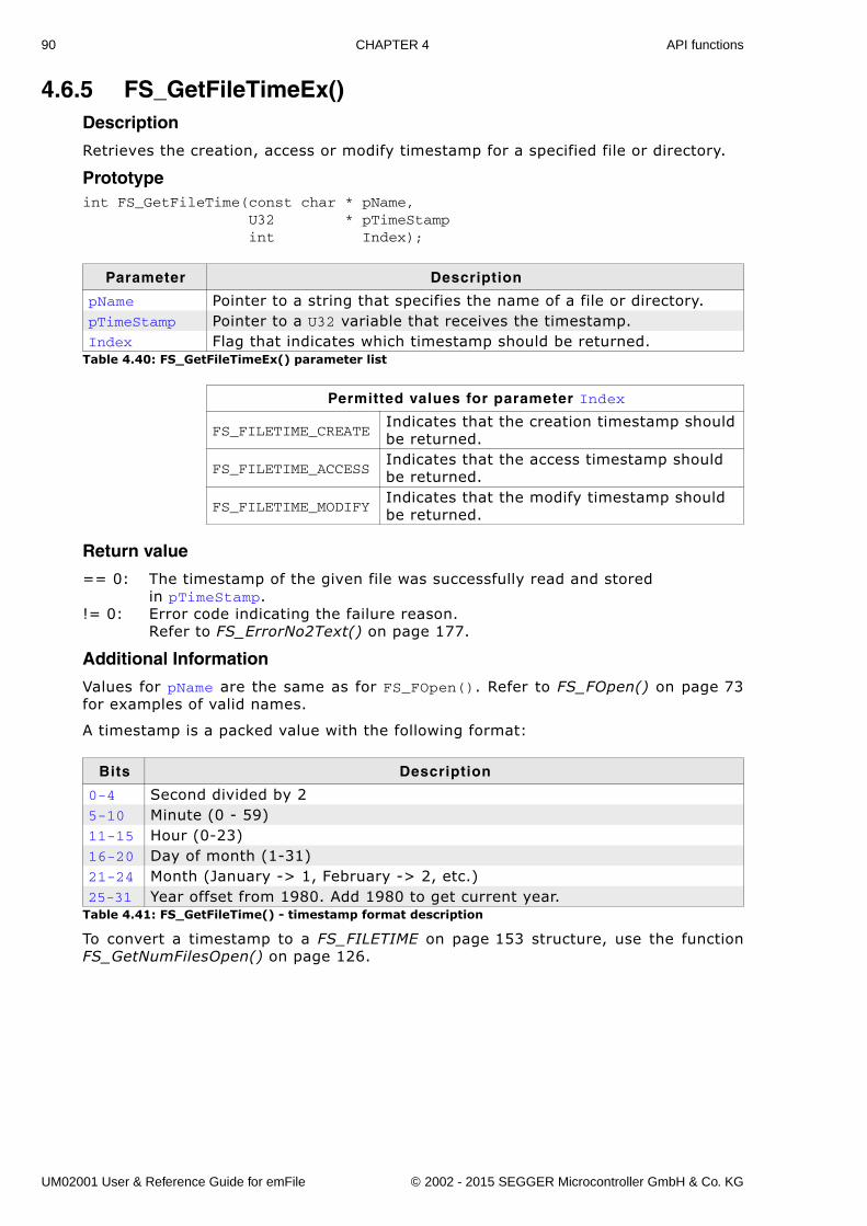
90 CHAPTER 4 API functions
4.6.5 FS_GetFileTimeEx()Description
Retrieves the creation, access or modify timestamp for a specified file or directory.
Prototypeint FS_GetFileTime(const char * pName, U32 * pTimeStamp int Index);
Return value
== 0: The timestamp of the given file was successfully read and storedin pTimeStamp.
!= 0: Error code indicating the failure reason.Refer to FS_ErrorNo2Text() on page 177.
Additional Information
Values for pName are the same as for FS_FOpen(). Refer to FS_FOpen() on page 73for examples of valid names.
A timestamp is a packed value with the following format:
To convert a timestamp to a FS_FILETIME on page 153 structure, use the functionFS_GetNumFilesOpen() on page 126.
Parameter Description
pName Pointer to a string that specifies the name of a file or directory.pTimeStamp Pointer to a U32 variable that receives the timestamp.Index Flag that indicates which timestamp should be returned.
Table 4.40: FS_GetFileTimeEx() parameter list
Permitted values for parameter Index
FS_FILETIME_CREATEIndicates that the creation timestamp should be returned.
FS_FILETIME_ACCESSIndicates that the access timestamp should be returned.
FS_FILETIME_MODIFYIndicates that the modify timestamp should be returned.
Bits Description
0-4 Second divided by 25-10 Minute (0 - 59)11-15 Hour (0-23)16-20 Day of month (1-31)21-24 Month (January -> 1, February -> 2, etc.)25-31 Year offset from 1980. Add 1980 to get current year.
Table 4.41: FS_GetFileTime() - timestamp format description
UM02001 User & Reference Guide for emFile © 2002 - 2015 SEGGER Microcontroller GmbH & Co. KG
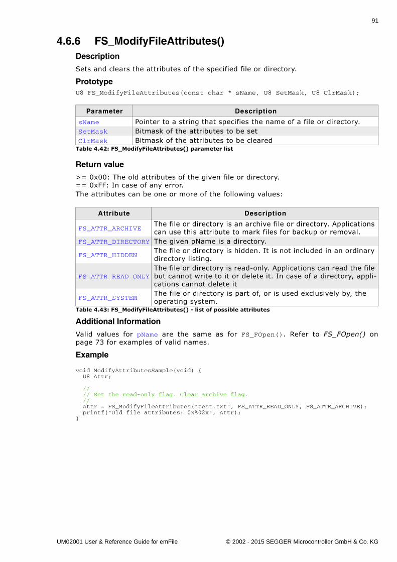
91
4.6.6 FS_ModifyFileAttributes()Description
Sets and clears the attributes of the specified file or directory.
PrototypeU8 FS_ModifyFileAttributes(const char * sName, U8 SetMask, U8 ClrMask);
Return value
>= 0x00: The old attributes of the given file or directory.== 0xFF: In case of any error.The attributes can be one or more of the following values:
Additional Information
Valid values for pName are the same as for FS_FOpen(). Refer to FS_FOpen() onpage 73 for examples of valid names.
Example
void ModifyAttributesSample(void) { U8 Attr;
// // Set the read-only flag. Clear archive flag. // Attr = FS_ModifyFileAttributes("test.txt", FS_ATTR_READ_ONLY, FS_ATTR_ARCHIVE); printf("Old file attributes: 0x%02x", Attr);}
Parameter Description
sName Pointer to a string that specifies the name of a file or directory.SetMask Bitmask of the attributes to be setClrMask Bitmask of the attributes to be cleared
Table 4.42: FS_ModifyFileAttributes() parameter list
Attribute Description
FS_ATTR_ARCHIVEThe file or directory is an archive file or directory. Applications can use this attribute to mark files for backup or removal.
FS_ATTR_DIRECTORY The given pName is a directory.
FS_ATTR_HIDDENThe file or directory is hidden. It is not included in an ordinary directory listing.
FS_ATTR_READ_ONLYThe file or directory is read-only. Applications can read the file but cannot write to it or delete it. In case of a directory, appli-cations cannot delete it
FS_ATTR_SYSTEMThe file or directory is part of, or is used exclusively by, the operating system.
Table 4.43: FS_ModifyFileAttributes() - list of possible attributes
UM02001 User & Reference Guide for emFile © 2002 - 2015 SEGGER Microcontroller GmbH & Co. KG
92 CHAPTER 4 API functions
4.6.7 FS_Move()Description
Moves an existing file or a directory, including its children.
Prototypeint FS_Move(const char * sExistingName, const char * sNewName);
Return value
== 0: If the file was successfully moved.!= 0: Error code indicating the failure reason.
Refer to FS_ErrorNo2Text() on page 177.
Additional Information
Valid values for sExistingName and sNewName are the same as for FS_FOpen(). Referto FS_FOpen() on page 73 for examples of valid names. The FS_Move() function willmove either a file or a directory (including its children) either in the same directoryor across directories. The file or directory you want to move has to be on the samevolume.
Example
void MainTask(void) { FS_Move("subdir1", "subdir2\\subdir3");}
Parameter Description
sExistingname Pointer to a string that names an existing file or directory.
sNewNamePointer to a string that specifies the name of the new file or directory.
Table 4.44: FS_Move() parameter list
UM02001 User & Reference Guide for emFile © 2002 - 2015 SEGGER Microcontroller GmbH & Co. KG
93
4.6.8 FS_Remove()Description
Removes an existing file.
Prototypeint FS_Remove(const char * pName);
Return value
== 0: If the file was successfully removed.!= 0: Error code indicating the failure reason.
Refer to FS_ErrorNo2Text() on page 177.
Additional Information
Valid values for pName are the same as for FS_FOpen(). Refer to FS_FOpen() onpage 73 for examples of valid names.
Example
void MainTask(void) { FS_Remove("test.txt");}
Parameter Description
pName Pointer to a string that specifies the file to be deleted.Table 4.45: FS_Remove() parameter list
UM02001 User & Reference Guide for emFile © 2002 - 2015 SEGGER Microcontroller GmbH & Co. KG
94 CHAPTER 4 API functions
4.6.9 FS_Rename()Description
Renames an existing file or a directory.
Prototypeint FS_Rename(const char * sExistingName, const char * sNewName);
Return value
== 0: If the file was successfully renamed.!= 0: Error code indicating the failure reason.
Refer to FS_ErrorNo2Text() on page 177.
Additional Information
Valid values for sExistingName and sNewName are the same as for FS_FOpen(). Referto FS_FOpen() on page 73 for examples of valid names. sNewName should only specifya valid file or directory name without a path.
Example
void MainTask(void) { FS_Rename("ram:\\subdir1", "subdir2");}
Parameter Description
sExistingName Pointer to a string that names an existing file or directory.
sNewNamePointer to a string that specifies the new name of the file or directory.
Table 4.46: FS_Rename() parameter list
UM02001 User & Reference Guide for emFile © 2002 - 2015 SEGGER Microcontroller GmbH & Co. KG
95
4.6.10 FS_SetEndOfFile()Description
Sets the end of file for the specified file.
Prototypeint FS_SetEndOfFile(FS_FILE * pFile);
Return value
== 0: End of File was set.!= 0: Error code indicating the failure reason.
Refer to FS_ErrorNo2Text() on page 177.
Additional Information
pFile should point to a file that has been opened with write permission. Refer toFS_FOpen() on page 73. This function can be used to truncate or extend a file. If thefile is extended, the contents of the file between the old EOF position and the newposition are not defined.
Example
void MainTask(void) { FS_FILE * pFile;
pFile = FS_FOpen("test.bin", "r+"); FS_SetFilePos(pFile, 2000); FS_SetEndOfFile(pFile); FS_FClose(pFile);}
Parameter Description
pFile Pointer to a data structure of type FS_FILE.Table 4.47: FS_SetEndOfFile() parameter list
UM02001 User & Reference Guide for emFile © 2002 - 2015 SEGGER Microcontroller GmbH & Co. KG
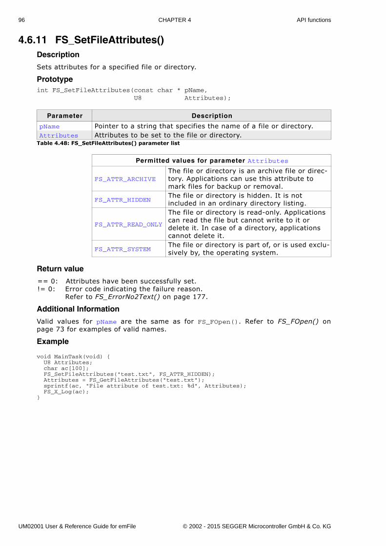
96 CHAPTER 4 API functions
4.6.11 FS_SetFileAttributes()Description
Sets attributes for a specified file or directory.
Prototypeint FS_SetFileAttributes(const char * pName, U8 Attributes);
Return value
== 0: Attributes have been successfully set.!= 0: Error code indicating the failure reason.
Refer to FS_ErrorNo2Text() on page 177.
Additional Information
Valid values for pName are the same as for FS_FOpen(). Refer to FS_FOpen() onpage 73 for examples of valid names.
Example
void MainTask(void) { U8 Attributes; char ac[100]; FS_SetFileAttributes("test.txt", FS_ATTR_HIDDEN); Attributes = FS_GetFileAttributes("test.txt"); sprintf(ac, "File attribute of test.txt: %d", Attributes); FS_X_Log(ac);}
Parameter Description
pName Pointer to a string that specifies the name of a file or directory.Attributes Attributes to be set to the file or directory.
Table 4.48: FS_SetFileAttributes() parameter list
Permitted values for parameter Attributes
FS_ATTR_ARCHIVEThe file or directory is an archive file or direc-tory. Applications can use this attribute to mark files for backup or removal.
FS_ATTR_HIDDENThe file or directory is hidden. It is not included in an ordinary directory listing.
FS_ATTR_READ_ONLY
The file or directory is read-only. Applications can read the file but cannot write to it or delete it. In case of a directory, applications cannot delete it.
FS_ATTR_SYSTEMThe file or directory is part of, or is used exclu-sively by, the operating system.
UM02001 User & Reference Guide for emFile © 2002 - 2015 SEGGER Microcontroller GmbH & Co. KG
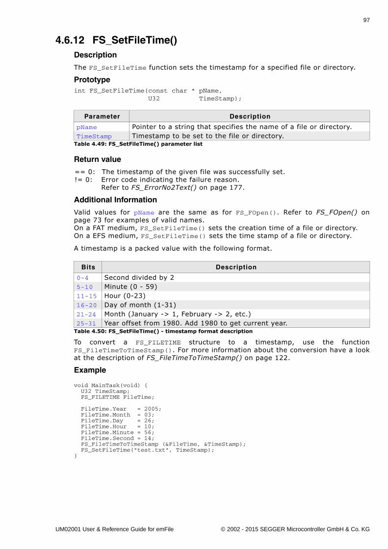
97
4.6.12 FS_SetFileTime()Description
The FS_SetFileTime function sets the timestamp for a specified file or directory.
Prototypeint FS_SetFileTime(const char * pName, U32 TimeStamp);
Return value
== 0: The timestamp of the given file was successfully set.!= 0: Error code indicating the failure reason.
Refer to FS_ErrorNo2Text() on page 177.
Additional Information
Valid values for pName are the same as for FS_FOpen(). Refer to FS_FOpen() onpage 73 for examples of valid names.On a FAT medium, FS_SetFileTime() sets the creation time of a file or directory.On a EFS medium, FS_SetFileTime() sets the time stamp of a file or directory.
A timestamp is a packed value with the following format.
To convert a FS_FILETIME structure to a timestamp, use the functionFS_FileTimeToTimeStamp(). For more information about the conversion have a lookat the description of FS_FileTimeToTimeStamp() on page 122.
Example
void MainTask(void) { U32 TimeStamp; FS_FILETIME FileTime;
FileTime.Year = 2005; FileTime.Month = 03; FileTime.Day = 26; FileTime.Hour = 10; FileTime.Minute = 56; FileTime.Second = 14; FS_FileTimeToTimeStamp (&FileTime, &TimeStamp); FS_SetFileTime("test.txt", TimeStamp);}
Parameter Description
pName Pointer to a string that specifies the name of a file or directory.TimeStamp Timestamp to be set to the file or directory.
Table 4.49: FS_SetFileTime() parameter list
Bits Description
0-4 Second divided by 25-10 Minute (0 - 59)11-15 Hour (0-23)16-20 Day of month (1-31)21-24 Month (January -> 1, February -> 2, etc.)25-31 Year offset from 1980. Add 1980 to get current year.
Table 4.50: FS_SetFileTime() - timestamp format description
UM02001 User & Reference Guide for emFile © 2002 - 2015 SEGGER Microcontroller GmbH & Co. KG
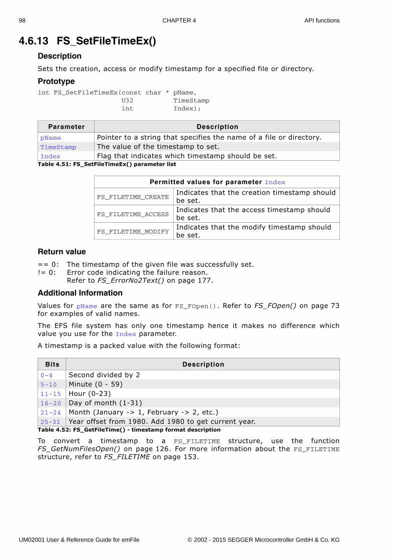
98 CHAPTER 4 API functions
4.6.13 FS_SetFileTimeEx()Description
Sets the creation, access or modify timestamp for a specified file or directory.
Prototypeint FS_SetFileTimeEx(const char * pName, U32 TimeStamp int Index);
Return value
== 0: The timestamp of the given file was successfully set.!= 0: Error code indicating the failure reason.
Refer to FS_ErrorNo2Text() on page 177.
Additional Information
Values for pName are the same as for FS_FOpen(). Refer to FS_FOpen() on page 73for examples of valid names.
The EFS file system has only one timestamp hence it makes no difference whichvalue you use for the Index parameter.
A timestamp is a packed value with the following format:
To convert a timestamp to a FS_FILETIME structure, use the functionFS_GetNumFilesOpen() on page 126. For more information about the FS_FILETIMEstructure, refer to FS_FILETIME on page 153.
Parameter Description
pName Pointer to a string that specifies the name of a file or directory.TimeStamp The value of the timestamp to set.Index Flag that indicates which timestamp should be set.
Table 4.51: FS_SetFileTimeEx() parameter list
Permitted values for parameter Index
FS_FILETIME_CREATEIndicates that the creation timestamp should be set.
FS_FILETIME_ACCESSIndicates that the access timestamp should be set.
FS_FILETIME_MODIFYIndicates that the modify timestamp should be set.
Bits Description
0-4 Second divided by 25-10 Minute (0 - 59)11-15 Hour (0-23)16-20 Day of month (1-31)21-24 Month (January -> 1, February -> 2, etc.)25-31 Year offset from 1980. Add 1980 to get current year.
Table 4.52: FS_GetFileTime() - timestamp format description
UM02001 User & Reference Guide for emFile © 2002 - 2015 SEGGER Microcontroller GmbH & Co. KG
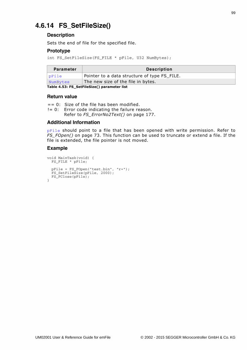
99
4.6.14 FS_SetFileSize()Description
Sets the end of file for the specified file.
Prototypeint FS_SetFileSize(FS_FILE * pFile, U32 NumBytes);
Return value
== 0: Size of the file has been modified.!= 0: Error code indicating the failure reason.
Refer to FS_ErrorNo2Text() on page 177.
Additional Information
pFile should point to a file that has been opened with write permission. Refer toFS_FOpen() on page 73. This function can be used to truncate or extend a file. If thefile is extended, the file pointer is not moved.
Example
void MainTask(void) { FS_FILE * pFile;
pFile = FS_FOpen("test.bin", "r+"); FS_SetFileSize(pFile, 2000); FS_FClose(pFile);}
Parameter Description
pFile Pointer to a data structure of type FS_FILE.NumBytes The new size of the file in bytes.
Table 4.53: FS_SetFileSize() parameter list
UM02001 User & Reference Guide for emFile © 2002 - 2015 SEGGER Microcontroller GmbH & Co. KG
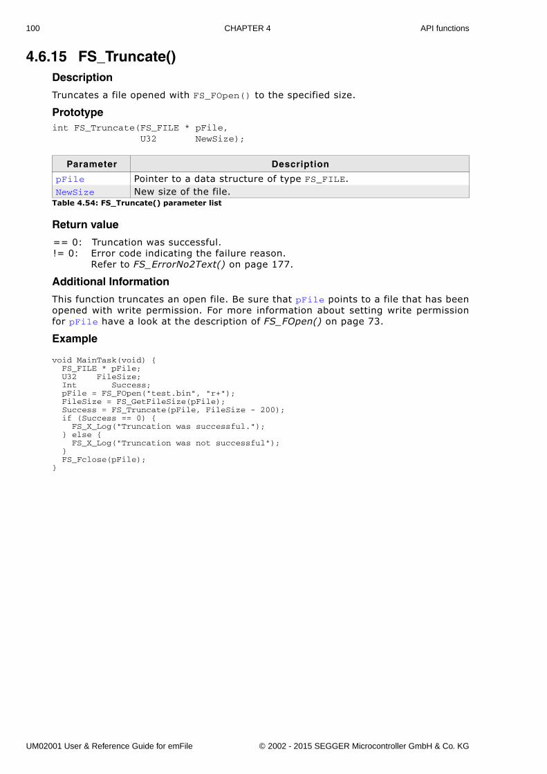
100 CHAPTER 4 API functions
4.6.15 FS_Truncate()Description
Truncates a file opened with FS_FOpen() to the specified size.
Prototypeint FS_Truncate(FS_FILE * pFile, U32 NewSize);
Return value
== 0: Truncation was successful.!= 0: Error code indicating the failure reason.
Refer to FS_ErrorNo2Text() on page 177.
Additional Information
This function truncates an open file. Be sure that pFile points to a file that has beenopened with write permission. For more information about setting write permissionfor pFile have a look at the description of FS_FOpen() on page 73.
Example
void MainTask(void) { FS_FILE * pFile; U32 FileSize; Int Success; pFile = FS_FOpen("test.bin", "r+"); FileSize = FS_GetFileSize(pFile); Success = FS_Truncate(pFile, FileSize - 200); if (Success == 0) { FS_X_Log("Truncation was successful."); } else { FS_X_Log("Truncation was not successful"); } FS_Fclose(pFile);}
Parameter Description
pFile Pointer to a data structure of type FS_FILE.NewSize New size of the file.
Table 4.54: FS_Truncate() parameter list
UM02001 User & Reference Guide for emFile © 2002 - 2015 SEGGER Microcontroller GmbH & Co. KG
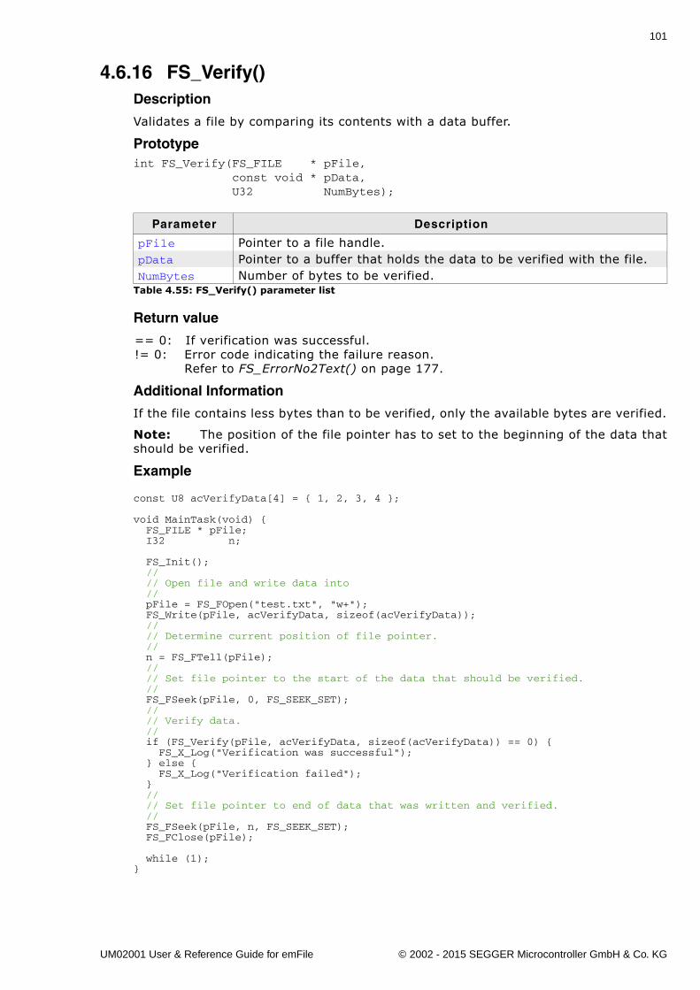
101
4.6.16 FS_Verify()Description
Validates a file by comparing its contents with a data buffer.
Prototypeint FS_Verify(FS_FILE * pFile, const void * pData, U32 NumBytes);
Return value
== 0: If verification was successful.!= 0: Error code indicating the failure reason.
Refer to FS_ErrorNo2Text() on page 177.
Additional Information
If the file contains less bytes than to be verified, only the available bytes are verified.
Note: The position of the file pointer has to set to the beginning of the data thatshould be verified.
Example
const U8 acVerifyData[4] = { 1, 2, 3, 4 };
void MainTask(void) { FS_FILE * pFile; I32 n;
FS_Init(); // // Open file and write data into // pFile = FS_FOpen("test.txt", "w+"); FS_Write(pFile, acVerifyData, sizeof(acVerifyData)); // // Determine current position of file pointer. // n = FS_FTell(pFile); // // Set file pointer to the start of the data that should be verified. // FS_FSeek(pFile, 0, FS_SEEK_SET); // // Verify data. // if (FS_Verify(pFile, acVerifyData, sizeof(acVerifyData)) == 0) { FS_X_Log("Verification was successful"); } else { FS_X_Log("Verification failed"); } // // Set file pointer to end of data that was written and verified. // FS_FSeek(pFile, n, FS_SEEK_SET); FS_FClose(pFile);
while (1);}
Parameter Description
pFile Pointer to a file handle.pData Pointer to a buffer that holds the data to be verified with the file.NumBytes Number of bytes to be verified.
Table 4.55: FS_Verify() parameter list
UM02001 User & Reference Guide for emFile © 2002 - 2015 SEGGER Microcontroller GmbH & Co. KG
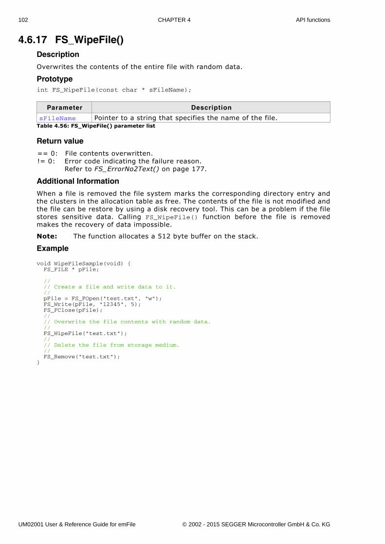
102 CHAPTER 4 API functions
4.6.17 FS_WipeFile()Description
Overwrites the contents of the entire file with random data.
Prototypeint FS_WipeFile(const char * sFileName);
Return value
== 0: File contents overwritten.!= 0: Error code indicating the failure reason.
Refer to FS_ErrorNo2Text() on page 177.
Additional Information
When a file is removed the file system marks the corresponding directory entry andthe clusters in the allocation table as free. The contents of the file is not modified andthe file can be restore by using a disk recovery tool. This can be a problem if the filestores sensitive data. Calling FS_WipeFile() function before the file is removedmakes the recovery of data impossible.
Note: The function allocates a 512 byte buffer on the stack.
Example
void WipeFileSample(void) { FS_FILE * pFile;
// // Create a file and write data to it. // pFile = FS_FOpen("test.txt", "w"); FS_Write(pFile, "12345", 5); FS_FClose(pFile); // // Overwrite the file contents with random data. // FS_WipeFile("test.txt"); // // Delete the file from storage medium. // FS_Remove("test.txt");}
Parameter Description
sFileName Pointer to a string that specifies the name of the file.Table 4.56: FS_WipeFile() parameter list
UM02001 User & Reference Guide for emFile © 2002 - 2015 SEGGER Microcontroller GmbH & Co. KG
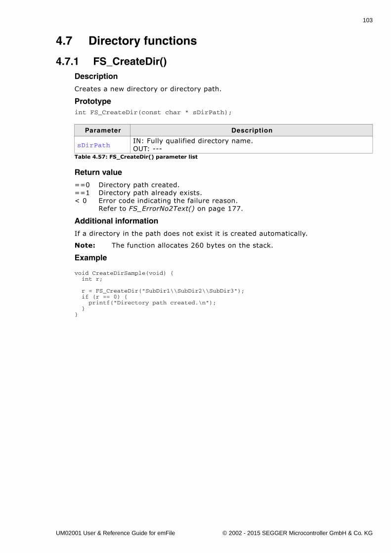
103
4.7 Directory functions
4.7.1 FS_CreateDir()Description
Creates a new directory or directory path.
Prototypeint FS_CreateDir(const char * sDirPath);
Return value
==0 Directory path created.==1 Directory path already exists.< 0 Error code indicating the failure reason.
Refer to FS_ErrorNo2Text() on page 177.
Additional information
If a directory in the path does not exist it is created automatically.
Note: The function allocates 260 bytes on the stack.
Example
void CreateDirSample(void) { int r;
r = FS_CreateDir("SubDir1\\SubDir2\\SubDir3"); if (r == 0) { printf("Directory path created.\n"); }}
Parameter Description
sDirPathIN: Fully qualified directory name.OUT: ---
Table 4.57: FS_CreateDir() parameter list
UM02001 User & Reference Guide for emFile © 2002 - 2015 SEGGER Microcontroller GmbH & Co. KG
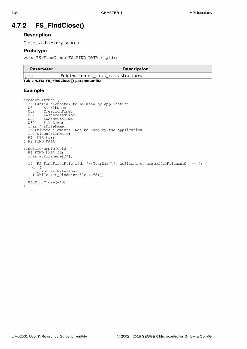
104 CHAPTER 4 API functions
4.7.2 FS_FindClose()Description
Closes a directory search.
Prototypevoid FS_FindClose(FS_FIND_DATA * pfd);
Example
typedef struct { // Public elements, to be used by application U8 Attributes; U32 CreationTime; U32 LastAccessTime; U32 LastWriteTime; U32 FileSize; char * sFileName; // Private elements. Not be used by the application int SizeofFileName; FS__DIR Dir;} FS_FIND_DATA;
FindFileSample(void) { FS_FIND_DATA fd; char acFilename[20];
if (FS_FindFirstFile(&fd, "\\YourDir\\", acFilename, sizeof(acFilename)) == 0) { do { printf(acFilename); } while (FS_FindNextFile (&fd)); } FS_FindClose(&fd);}
Parameter Description
pfd Pointer to a FS_FIND_DATA structure.Table 4.58: FS_FindClose() parameter list
UM02001 User & Reference Guide for emFile © 2002 - 2015 SEGGER Microcontroller GmbH & Co. KG
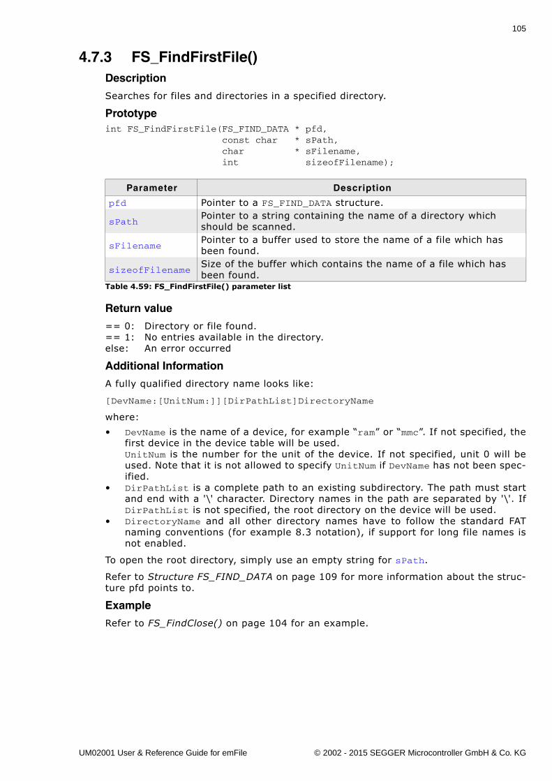
105
4.7.3 FS_FindFirstFile()Description
Searches for files and directories in a specified directory.
Prototypeint FS_FindFirstFile(FS_FIND_DATA * pfd, const char * sPath, char * sFilename, int sizeofFilename);
Return value
== 0: Directory or file found.== 1: No entries available in the directory.else: An error occurred
Additional Information
A fully qualified directory name looks like:
[DevName:[UnitNum:]][DirPathList]DirectoryName
where:
� DevName is the name of a device, for example �ram� or �mmc�. If not specified, thefirst device in the device table will be used.UnitNum is the number for the unit of the device. If not specified, unit 0 will beused. Note that it is not allowed to specify UnitNum if DevName has not been spec-ified.
� DirPathList is a complete path to an existing subdirectory. The path must startand end with a '\' character. Directory names in the path are separated by '\'. IfDirPathList is not specified, the root directory on the device will be used.
� DirectoryName and all other directory names have to follow the standard FATnaming conventions (for example 8.3 notation), if support for long file names isnot enabled.
To open the root directory, simply use an empty string for sPath.
Refer to Structure FS_FIND_DATA on page 109 for more information about the struc-ture pfd points to.
Example
Refer to FS_FindClose() on page 104 for an example.
Parameter Description
pfd Pointer to a FS_FIND_DATA structure.
sPathPointer to a string containing the name of a directory which should be scanned.
sFilenamePointer to a buffer used to store the name of a file which has been found.
sizeofFilenameSize of the buffer which contains the name of a file which has been found.
Table 4.59: FS_FindFirstFile() parameter list
UM02001 User & Reference Guide for emFile © 2002 - 2015 SEGGER Microcontroller GmbH & Co. KG
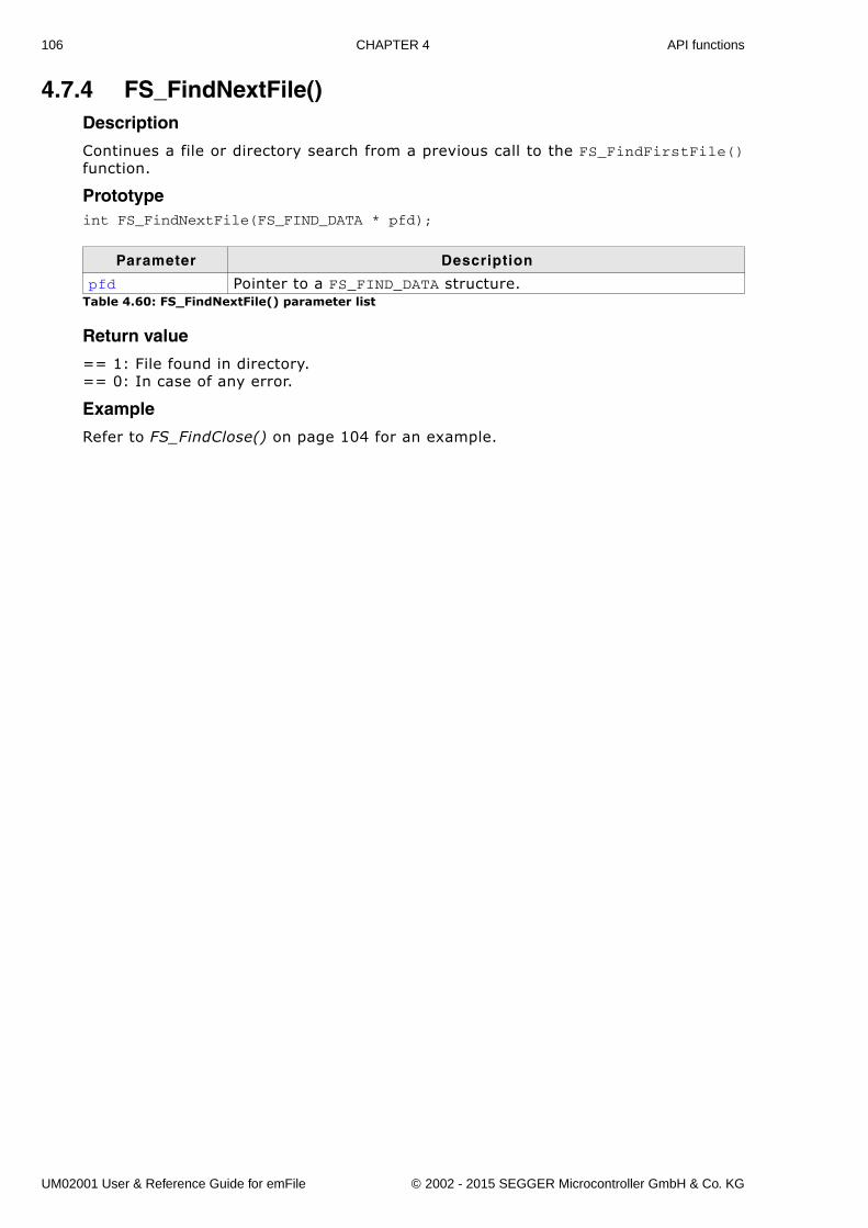
106 CHAPTER 4 API functions
4.7.4 FS_FindNextFile()Description
Continues a file or directory search from a previous call to the FS_FindFirstFile()function.
Prototypeint FS_FindNextFile(FS_FIND_DATA * pfd);
Return value
== 1: File found in directory.== 0: In case of any error.
Example
Refer to FS_FindClose() on page 104 for an example.
Parameter Description
pfd Pointer to a FS_FIND_DATA structure.Table 4.60: FS_FindNextFile() parameter list
UM02001 User & Reference Guide for emFile © 2002 - 2015 SEGGER Microcontroller GmbH & Co. KG
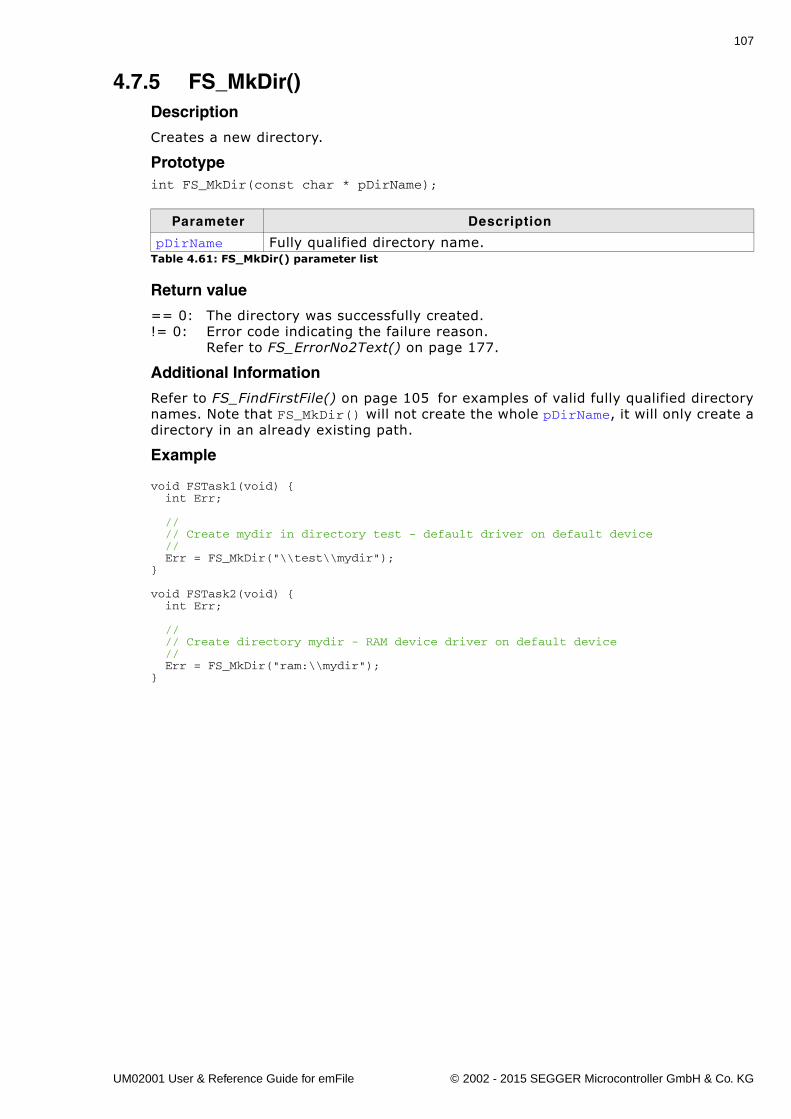
107
4.7.5 FS_MkDir()Description
Creates a new directory.
Prototypeint FS_MkDir(const char * pDirName);
Return value
== 0: The directory was successfully created.!= 0: Error code indicating the failure reason.
Refer to FS_ErrorNo2Text() on page 177.
Additional Information
Refer to FS_FindFirstFile() on page 105 for examples of valid fully qualified directorynames. Note that FS_MkDir() will not create the whole pDirName, it will only create adirectory in an already existing path.
Example
void FSTask1(void) { int Err;
// // Create mydir in directory test - default driver on default device // Err = FS_MkDir("\\test\\mydir");}
void FSTask2(void) { int Err; // // Create directory mydir - RAM device driver on default device // Err = FS_MkDir("ram:\\mydir");}
Parameter Description
pDirName Fully qualified directory name.Table 4.61: FS_MkDir() parameter list
UM02001 User & Reference Guide for emFile © 2002 - 2015 SEGGER Microcontroller GmbH & Co. KG
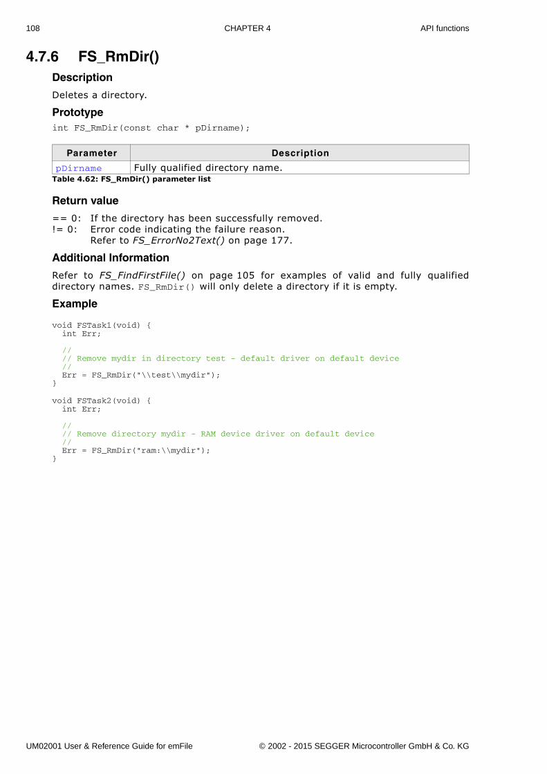
108 CHAPTER 4 API functions
4.7.6 FS_RmDir()Description
Deletes a directory.
Prototypeint FS_RmDir(const char * pDirname);
Return value
== 0: If the directory has been successfully removed.!= 0: Error code indicating the failure reason.
Refer to FS_ErrorNo2Text() on page 177.
Additional Information
Refer to FS_FindFirstFile() on page 105 for examples of valid and fully qualifieddirectory names. FS_RmDir() will only delete a directory if it is empty.
Example
void FSTask1(void) { int Err;
// // Remove mydir in directory test - default driver on default device // Err = FS_RmDir("\\test\\mydir");}
void FSTask2(void) { int Err;
// // Remove directory mydir - RAM device driver on default device // Err = FS_RmDir("ram:\\mydir");}
Parameter Description
pDirname Fully qualified directory name.Table 4.62: FS_RmDir() parameter list
UM02001 User & Reference Guide for emFile © 2002 - 2015 SEGGER Microcontroller GmbH & Co. KG
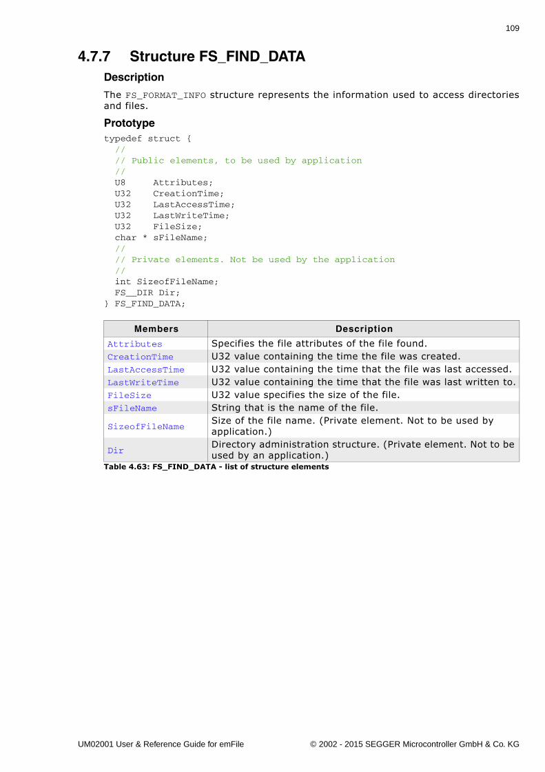
109
4.7.7 Structure FS_FIND_DATADescription
The FS_FORMAT_INFO structure represents the information used to access directoriesand files.
Prototypetypedef struct { // // Public elements, to be used by application // U8 Attributes; U32 CreationTime; U32 LastAccessTime; U32 LastWriteTime; U32 FileSize; char * sFileName; // // Private elements. Not be used by the application // int SizeofFileName; FS__DIR Dir;} FS_FIND_DATA;
Members Description
Attributes Specifies the file attributes of the file found.CreationTime U32 value containing the time the file was created.LastAccessTime U32 value containing the time that the file was last accessed.LastWriteTime U32 value containing the time that the file was last written to.FileSize U32 value specifies the size of the file.sFileName String that is the name of the file.
SizeofFileNameSize of the file name. (Private element. Not to be used by application.)
DirDirectory administration structure. (Private element. Not to be used by an application.)
Table 4.63: FS_FIND_DATA - list of structure elements
UM02001 User & Reference Guide for emFile © 2002 - 2015 SEGGER Microcontroller GmbH & Co. KG
110 CHAPTER 4 API functions
4.8 Formatting a mediumIn general, before a medium can be used to read or write to a file, it needs to be for-matted. Flash cards are usually already preformatted and do not need to be format-ted. Flashes used as storage devices have normally to be reformatted. These devicesrequire a low-level format first, then a high-level format. The low-level format isdevice-specific, the high-level format depends on the file system only. (FAT-formattypically).
UM02001 User & Reference Guide for emFile © 2002 - 2015 SEGGER Microcontroller GmbH & Co. KG
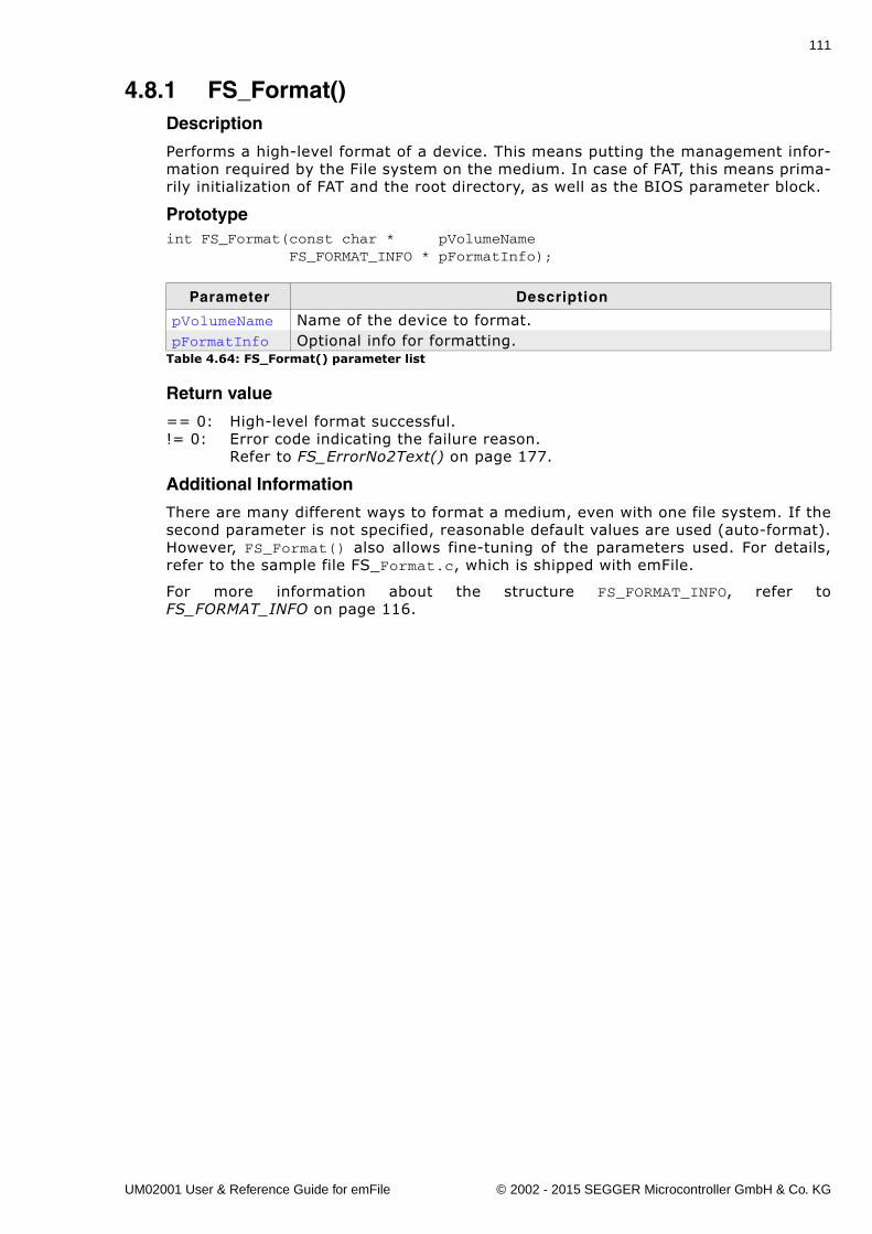
111
4.8.1 FS_Format()Description
Performs a high-level format of a device. This means putting the management infor-mation required by the File system on the medium. In case of FAT, this means prima-rily initialization of FAT and the root directory, as well as the BIOS parameter block.
Prototypeint FS_Format(const char * pVolumeName FS_FORMAT_INFO * pFormatInfo);
Return value
== 0: High-level format successful.!= 0: Error code indicating the failure reason.
Refer to FS_ErrorNo2Text() on page 177.
Additional Information
There are many different ways to format a medium, even with one file system. If thesecond parameter is not specified, reasonable default values are used (auto-format).However, FS_Format() also allows fine-tuning of the parameters used. For details,refer to the sample file FS_Format.c, which is shipped with emFile.
For more information about the structure FS_FORMAT_INFO, refer toFS_FORMAT_INFO on page 116.
Parameter Description
pVolumeName Name of the device to format.pFormatInfo Optional info for formatting.
Table 4.64: FS_Format() parameter list
UM02001 User & Reference Guide for emFile © 2002 - 2015 SEGGER Microcontroller GmbH & Co. KG
112 CHAPTER 4 API functions
4.8.2 FS_FormatLLIfRequired()Description
Checks if the volume is low-level formatted and formats the volume if required.
Prototypeint FS_FormatLLIfRequired(const char * pVolumeName);
Return value
== 0: Ok - low-level format successful.== 1: Low-level format not required.< 0: Error code indicating the failure reason.
Refer to FS_ErrorNo2Text() on page 177.
Additional Information
Low-level format is only required for devices which have their own managementlevel. These are the drivers for NOR flashes, NAND flashes. MMC, SD and all othercards do not require a low-level format.
Parameter Description
pVolumeName Name of the device to low-level format.Table 4.65: FS_FormatLLIfRequired() parameter list
UM02001 User & Reference Guide for emFile © 2002 - 2015 SEGGER Microcontroller GmbH & Co. KG
113
4.8.3 FS_FormatLow()Description
Low-level formats a device. Required by NAND/NOR flashes prior to format.
Prototypeint FS_FormatLow(const char * pDeviceName);
Return value
== 0: Low-level format successful.!= 0: Error code indicating the failure reason.
Refer to FS_ErrorNo2Text() on page 177.
Additional Information
Low-level format is only required for devices which have their own managementlevel. These are the drivers for NOR flashes, NAND flashes and SMC cards. MMC, SDand all other cards do not require a low-level format.
Parameter Description
pVolumeName Name of the device to low-level format.Table 4.66: FS_FormatLow() parameter list
UM02001 User & Reference Guide for emFile © 2002 - 2015 SEGGER Microcontroller GmbH & Co. KG
114 CHAPTER 4 API functions
4.8.4 FS_IsHLFormatted()Description
Checks if the volume is high-level formatted.
Prototypeint FS_IsHLFormatted(const char * sVolumeName);
Return value
== 1: Volume is high-level formatted.== 0: Volume is not high-level formatted.< 0: Error code indicating the failure reason.
Refer to FS_ErrorNo2Text() on page 177.
Additional information
This function can be use to determine if the format of a partition is supported by theemFile. If the partition format is unknown the function returns 0.
Parameter Description
pVolumeName Name of the device to check.Table 4.67: FS_IsHLFormatted() parameter list
UM02001 User & Reference Guide for emFile © 2002 - 2015 SEGGER Microcontroller GmbH & Co. KG
115
4.8.5 FS_IsLLFormatted()Description
Checks if the volume is low-level formatted.
Prototypeint FS_IsHLFormatted(const char * sVolumeName);
Return value
== 1: Volume is low-level formatted.== 0: Volume is not low-level formatted.< 0: Error code indicating the failure reason.
Refer to FS_ErrorNo2Text() on page 177.
Additional Information
Low-level format is only required for devices which have their own managementlevel. These are the drivers for NOR flashes, NAND flashes. MMC, SD and all othercards do not require a low-level format.
Parameter Description
sVolumeName Name of the device to check.Table 4.68: FS_IsLLFormatted() parameter list
UM02001 User & Reference Guide for emFile © 2002 - 2015 SEGGER Microcontroller GmbH & Co. KG
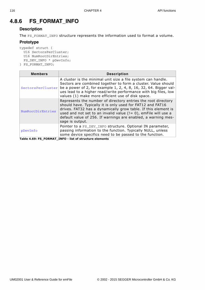
116 CHAPTER 4 API functions
4.8.6 FS_FORMAT_INFODescription
The FS_FORMAT_INFO structure represents the information used to format a volume.
Prototypetypedef struct { U16 SectorsPerCluster; U16 NumRootDirEntries; FS_DEV_INFO * pDevInfo;} FS_FORMAT_INFO;
Members Description
SectorsPerCluster
A cluster is the minimal unit size a file system can handle. Sectors are combined together to form a cluster. Value should be a power of 2, for example 1, 2, 4, 8, 16, 32, 64. Bigger val-ues lead to a higher read/write performance with big files, low values (1) make more efficient use of disk space.
NumRootDirEntries
Represents the number of directory entries the root directory should have. Typically it is only used for FAT12 and FAT16 drives. FAT32 has a dynamically grow table. If this element is used and not set to an invalid value (!= 0), emFile will use a default value of 256. If warnings are enabled, a warning mes-sage is output.
pDevInfoPointer to a FS_DEV_INFO structure. Optional IN parameter, passing information to the function. Typically NULL, unless some device specifics need to be passed to the function.
Table 4.69: FS_FORMAT_INFO - list of structure elements
UM02001 User & Reference Guide for emFile © 2002 - 2015 SEGGER Microcontroller GmbH & Co. KG
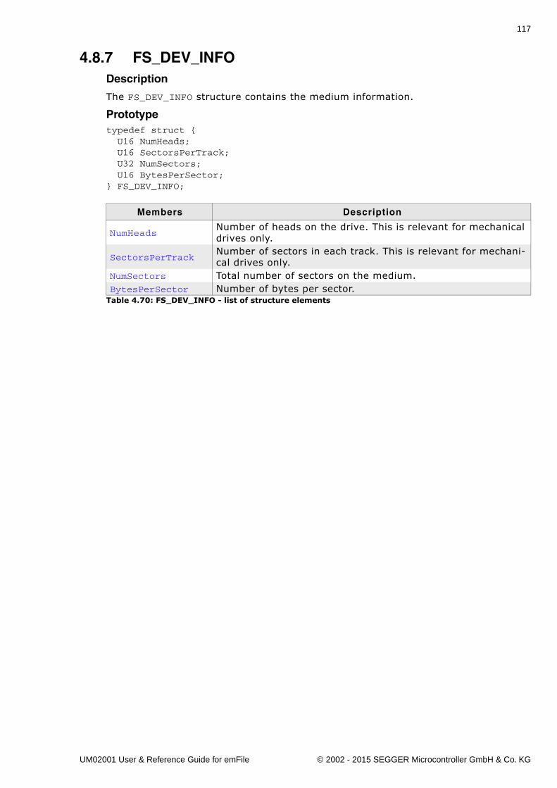
117
4.8.7 FS_DEV_INFODescription
The FS_DEV_INFO structure contains the medium information.
Prototypetypedef struct { U16 NumHeads; U16 SectorsPerTrack; U32 NumSectors; U16 BytesPerSector;} FS_DEV_INFO;
Members Description
NumHeadsNumber of heads on the drive. This is relevant for mechanical drives only.
SectorsPerTrackNumber of sectors in each track. This is relevant for mechani-cal drives only.
NumSectors Total number of sectors on the medium.BytesPerSector Number of bytes per sector.
Table 4.70: FS_DEV_INFO - list of structure elements
UM02001 User & Reference Guide for emFile © 2002 - 2015 SEGGER Microcontroller GmbH & Co. KG
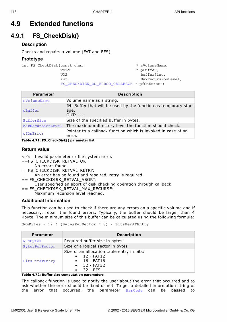
118 CHAPTER 4 API functions
4.9 Extended functions
4.9.1 FS_CheckDisk()Description
Checks and repairs a volume (FAT and EFS).
Prototypeint FS_CheckDisk(const char * sVolumeName, void * pBuffer, U32 BufferSize, int MaxRecursionLevel, FS_CHECKDISK_ON_ERROR_CALLBACK * pfOnError);
Return value
< 0: Invalid parameter or file system error.==FS_CHECKDISK_RETVAL_OK:
No errors found.==FS_CHECKDISK_RETVAL_RETRY: An error has be found and repaired, retry is required.== FS_CHECKDISK_RETVAL_ABORT:
User specified an abort of disk checking operation through callback.== FS_CHECKDISK_RETVAL_MAX_RECURSE:
Maximum recursion level reached.
Additional Information
This function can be used to check if there are any errors on a specific volume and ifnecessary, repair the found errors. Typically, the buffer should be larger than 4Kbyte. The minimum size of this buffer can be calculated using the following formula:
NumBytes = 12 * (BytesPerSector * 8) / BitsPerATEntry
The callback function is used to notify the user about the error that occurred and toask whether the error should be fixed or not. To get a detailed information string ofthe error that occurred, the parameter ErrCode can be passed to
Parameter Description
sVolumeName Volume name as a string.
pBufferIN: Buffer that will be used by the function as temporary stor-age.OUT: ---
BufferSize Size of the specified buffer in bytes.MaxRecursionLevel The maximum directory level the function should check.
pfOnErrorPointer to a callback function which is invoked in case of an error.
Table 4.71: FS_CheckDisk() parameter list
Parameter Description
NumBytes Required buffer size in bytesBytesPerSector Size of a logical sector in bytes
BitsPerATEntry
Size of an allocation table entry in bits:� 12 - FAT12� 16 - FAT16� 32 - FAT32� 32 - EFS
Table 4.72: Buffer size computation parameters
UM02001 User & Reference Guide for emFile © 2002 - 2015 SEGGER Microcontroller GmbH & Co. KG
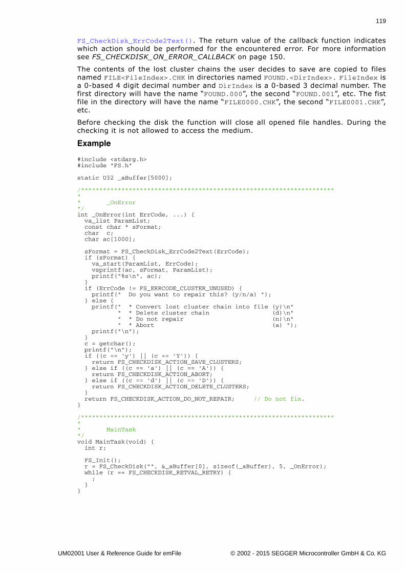
119
FS_CheckDisk_ErrCode2Text(). The return value of the callback function indicateswhich action should be performed for the encountered error. For more informationsee FS_CHECKDISK_ON_ERROR_CALLBACK on page 150.
The contents of the lost cluster chains the user decides to save are copied to filesnamed FILE<FileIndex>.CHK in directories named FOUND.<DirIndex>. FileIndex isa 0-based 4 digit decimal number and DirIndex is a 0-based 3 decimal number. Thefirst directory will have the name �FOUND.000�, the second �FOUND.001�, etc. The fistfile in the directory will have the name �FILE0000.CHK�, the second �FILE0001.CHK�,etc.
Before checking the disk the function will close all opened file handles. During thechecking it is not allowed to access the medium.
Example
#include <stdarg.h>#include "FS.h"
static U32 _aBuffer[5000];
/*********************************************************************** _OnError*/int _OnError(int ErrCode, ...) { va_list ParamList; const char * sFormat; char c; char ac[1000];
sFormat = FS_CheckDisk_ErrCode2Text(ErrCode); if (sFormat) { va_start(ParamList, ErrCode); vsprintf(ac, sFormat, ParamList); printf("%s\n", ac); } if (ErrCode != FS_ERRCODE_CLUSTER_UNUSED) { printf(" Do you want to repair this? (y/n/a) "); } else { printf(" * Convert lost cluster chain into file (y)\n" " * Delete cluster chain (d)\n" " * Do not repair (n)\n" " * Abort (a) "); printf("\n"); } c = getchar(); printf("\n"); if ((c == 'y') || (c == 'Y')) { return FS_CHECKDISK_ACTION_SAVE_CLUSTERS; } else if ((c == 'a') || (c == 'A')) { return FS_CHECKDISK_ACTION_ABORT; } else if ((c == 'd') || (c == 'D')) { return FS_CHECKDISK_ACTION_DELETE_CLUSTERS; } return FS_CHECKDISK_ACTION_DO_NOT_REPAIR; // Do not fix.}
/*********************************************************************** MainTask*/void MainTask(void) { int r;
FS_Init(); r = FS_CheckDisk("", &_aBuffer[0], sizeof(_aBuffer), 5, _OnError); while (r == FS_CHECKDISK_RETVAL_RETRY) { ; }}
UM02001 User & Reference Guide for emFile © 2002 - 2015 SEGGER Microcontroller GmbH & Co. KG
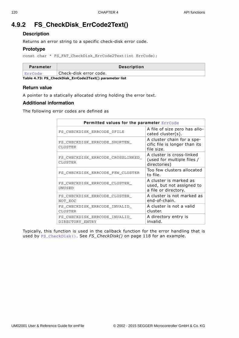
120 CHAPTER 4 API functions
4.9.2 FS_CheckDisk_ErrCode2Text()Description
Returns an error string to a specific check-disk error code.
Prototypeconst char * FS_FAT_CheckDisk_ErrCode2Text(int ErrCode);
Return value
A pointer to a statically allocated string holding the error text.
Additional information
The following error codes are defined as
Typically, this function is used in the callback function for the error handling that isused by FS_CheckDisk(). See FS_CheckDisk() on page 118 for an example.
Parameter Description
ErrCode Check-disk error code.Table 4.73: FS_CheckDisk_ErrCode2Text() parameter list
Permitted values for the parameter ErrCode
FS_CHECKDISK_ERRCODE_0FILEA file of size zero has allo-cated cluster(s).
FS_CHECKDISK_ERRCODE_SHORTEN_CLUSTER
A cluster chain for a spe-cific file is longer than its file size.
FS_CHECKDISK_ERRCODE_CROSSLINKED_CLUSTER
A cluster is cross-linked (used for multiple files / directories)
FS_CHECKDISK_ERRCODE_FEW_CLUSTERToo few clusters allocated to file.
FS_CHECKDISK_ERRCODE_CLUSTER_UNUSED
A cluster is marked as used, but not assigned to a file or directory.
FS_CHECKDISK_ERRCODE_CLUSTER_NOT_EOC
A cluster is not marked as end-of-chain.
FS_CHECKDISK_ERRCODE_INVALID_CLUSTER
A cluster is not a valid cluster.
FS_CHECKDISK_ERRCODE_INVALID_DIRECTORY_ENTRY
A directory entry is invalid.
UM02001 User & Reference Guide for emFile © 2002 - 2015 SEGGER Microcontroller GmbH & Co. KG
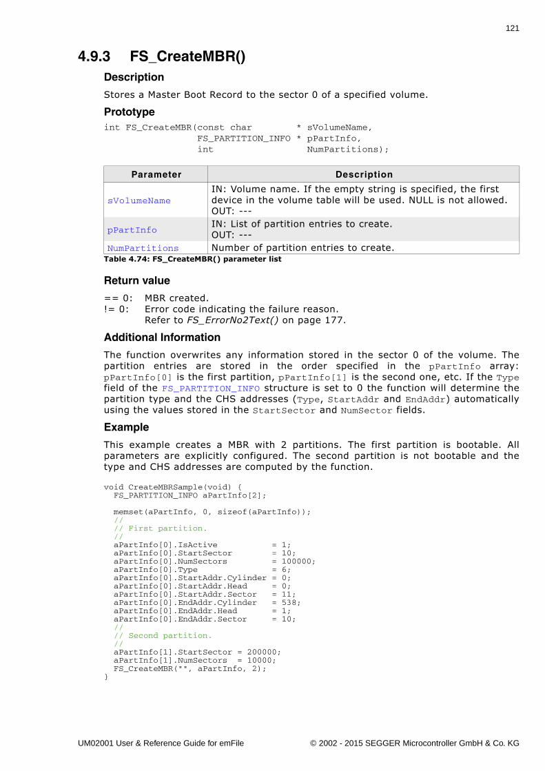
121
4.9.3 FS_CreateMBR()Description
Stores a Master Boot Record to the sector 0 of a specified volume.
Prototypeint FS_CreateMBR(const char * sVolumeName, FS_PARTITION_INFO * pPartInfo, int NumPartitions);
Return value
== 0: MBR created.!= 0: Error code indicating the failure reason.
Refer to FS_ErrorNo2Text() on page 177.
Additional Information
The function overwrites any information stored in the sector 0 of the volume. Thepartition entries are stored in the order specified in the pPartInfo array:pPartInfo[0] is the first partition, pPartInfo[1] is the second one, etc. If the Typefield of the FS_PARTITION_INFO structure is set to 0 the function will determine thepartition type and the CHS addresses (Type, StartAddr and EndAddr) automaticallyusing the values stored in the StartSector and NumSector fields.
Example
This example creates a MBR with 2 partitions. The first partition is bootable. Allparameters are explicitly configured. The second partition is not bootable and thetype and CHS addresses are computed by the function.
void CreateMBRSample(void) { FS_PARTITION_INFO aPartInfo[2];
memset(aPartInfo, 0, sizeof(aPartInfo)); // // First partition. // aPartInfo[0].IsActive = 1; aPartInfo[0].StartSector = 10; aPartInfo[0].NumSectors = 100000; aPartInfo[0].Type = 6; aPartInfo[0].StartAddr.Cylinder = 0; aPartInfo[0].StartAddr.Head = 0; aPartInfo[0].StartAddr.Sector = 11; aPartInfo[0].EndAddr.Cylinder = 538; aPartInfo[0].EndAddr.Head = 1; aPartInfo[0].EndAddr.Sector = 10; // // Second partition. // aPartInfo[1].StartSector = 200000; aPartInfo[1].NumSectors = 10000; FS_CreateMBR("", aPartInfo, 2);}
Parameter Description
sVolumeNameIN: Volume name. If the empty string is specified, the first device in the volume table will be used. NULL is not allowed.OUT: ---
pPartInfoIN: List of partition entries to create.OUT: ---
NumPartitions Number of partition entries to create.Table 4.74: FS_CreateMBR() parameter list
UM02001 User & Reference Guide for emFile © 2002 - 2015 SEGGER Microcontroller GmbH & Co. KG
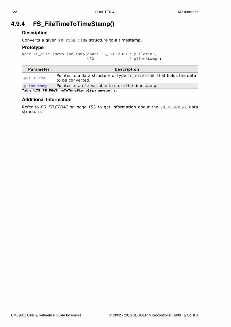
122 CHAPTER 4 API functions
4.9.4 FS_FileTimeToTimeStamp()Description
Converts a given FS_FILE_TIME structure to a timestamp.
Prototypevoid FS_FileTimeToTimeStamp(const FS_FILETIME * pFileTime, U32 * pTimeStamp);
Additional Information
Refer to FS_FILETIME on page 153 to get information about the FS_FILETIME datastructure.
Parameter Description
pFileTimePointer to a data structure of type FS_FILETIME, that holds the data to be converted.
pTimeStamp Pointer to a U32 variable to store the timestamp.Table 4.75: FS_FileTimeToTimeStamp() parameter list
UM02001 User & Reference Guide for emFile © 2002 - 2015 SEGGER Microcontroller GmbH & Co. KG
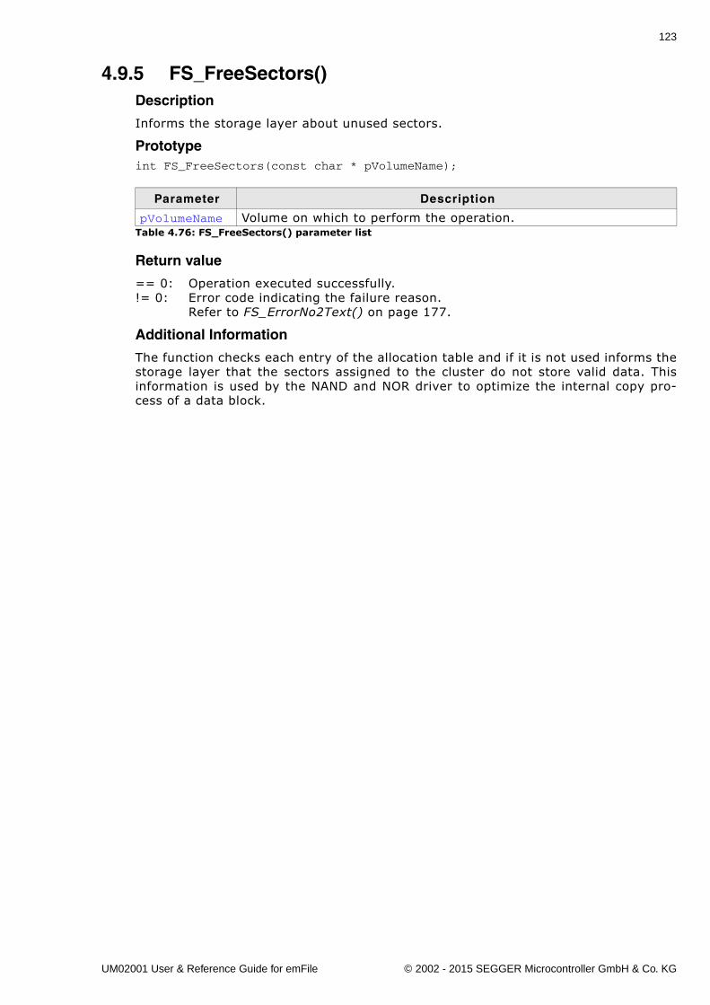
123
4.9.5 FS_FreeSectors()Description
Informs the storage layer about unused sectors.
Prototypeint FS_FreeSectors(const char * pVolumeName);
Return value
== 0: Operation executed successfully.!= 0: Error code indicating the failure reason.
Refer to FS_ErrorNo2Text() on page 177.
Additional Information
The function checks each entry of the allocation table and if it is not used informs thestorage layer that the sectors assigned to the cluster do not store valid data. Thisinformation is used by the NAND and NOR driver to optimize the internal copy pro-cess of a data block.
Parameter Description
pVolumeName Volume on which to perform the operation.Table 4.76: FS_FreeSectors() parameter list
UM02001 User & Reference Guide for emFile © 2002 - 2015 SEGGER Microcontroller GmbH & Co. KG
124 CHAPTER 4 API functions
4.9.6 FS_GetFileSize()Description
Gets the current file size of a file.
PrototypeU32 FS_GetFileSize(FS_FILE * pFile);
Return Value
>= 0: File size in bytes (0 - 0xFFFFFFFE).== 0xFFFFFFFF: In case of any error.
Parameter Description
pFile Pointer to a data structure of type FS_FILE.Table 4.77: FS_GetFileSize() parameter list
UM02001 User & Reference Guide for emFile © 2002 - 2015 SEGGER Microcontroller GmbH & Co. KG
125
4.9.7 FS_GetMaxSectorSize()Description
Returns the size of the configured logical sector.
PrototypeU32 FS_GetMaxSectorSize(void);
Return Value
Size of a logical sector in bytes.
UM02001 User & Reference Guide for emFile © 2002 - 2015 SEGGER Microcontroller GmbH & Co. KG
126 CHAPTER 4 API functions
4.9.8 FS_GetNumFilesOpen()Description
Returns the number of opened files.
Prototypeint FS_GetNumFilesOpen(void);
Return Value
Number of opened file handles.
UM02001 User & Reference Guide for emFile © 2002 - 2015 SEGGER Microcontroller GmbH & Co. KG
127
4.9.9 FS_GetNumVolumes()Description
Retrieves the number of available volumes.
Prototypeint FS_GetNumVolumes(void);
Return Value
The number of available volumes.
Additional Information
This function can be used to get the name of each available volume. Refer toFS_GetVolumeName() on page 135 for getting more information.
UM02001 User & Reference Guide for emFile © 2002 - 2015 SEGGER Microcontroller GmbH & Co. KG
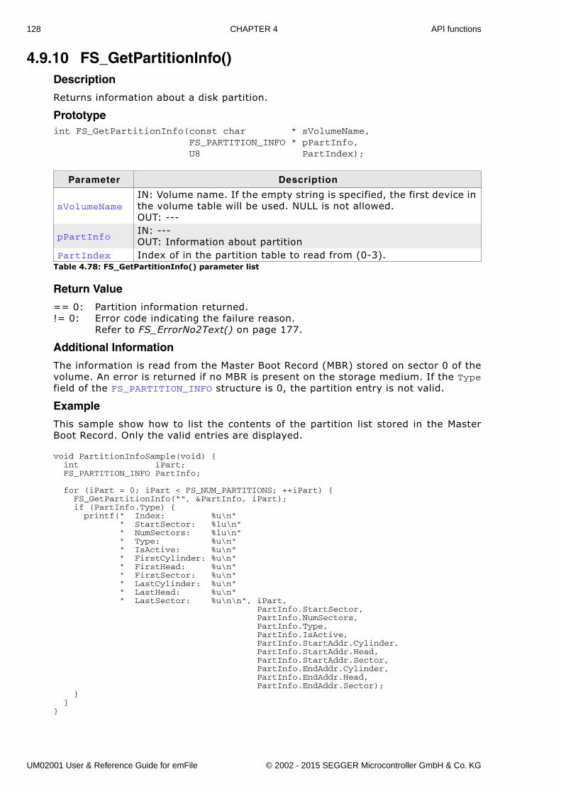
128 CHAPTER 4 API functions
4.9.10 FS_GetPartitionInfo()Description
Returns information about a disk partition.
Prototypeint FS_GetPartitionInfo(const char * sVolumeName, FS_PARTITION_INFO * pPartInfo, U8 PartIndex);
Return Value
== 0: Partition information returned. != 0: Error code indicating the failure reason.
Refer to FS_ErrorNo2Text() on page 177.
Additional Information
The information is read from the Master Boot Record (MBR) stored on sector 0 of thevolume. An error is returned if no MBR is present on the storage medium. If the Typefield of the FS_PARTITION_INFO structure is 0, the partition entry is not valid.
Example
This sample show how to list the contents of the partition list stored in the MasterBoot Record. Only the valid entries are displayed.
void PartitionInfoSample(void) { int iPart; FS_PARTITION_INFO PartInfo;
for (iPart = 0; iPart < FS_NUM_PARTITIONS; ++iPart) { FS_GetPartitionInfo(““, &PartInfo, iPart); if (PartInfo.Type) { printf(" Index: %u\n" " StartSector: %lu\n" " NumSectors: %lu\n" " Type: %u\n" " IsActive: %u\n" " FirstCylinder: %u\n" " FirstHead: %u\n" " FirstSector: %u\n" " LastCylinder: %u\n" " LastHead: %u\n" " LastSector: %u\n\n", iPart, PartInfo.StartSector, PartInfo.NumSectors, PartInfo.Type, PartInfo.IsActive, PartInfo.StartAddr.Cylinder, PartInfo.StartAddr.Head, PartInfo.StartAddr.Sector, PartInfo.EndAddr.Cylinder, PartInfo.EndAddr.Head, PartInfo.EndAddr.Sector); } }}
Parameter Description
sVolumeNameIN: Volume name. If the empty string is specified, the first device in the volume table will be used. NULL is not allowed.OUT: ---
pPartInfoIN: ---OUT: Information about partition
PartIndex Index of in the partition table to read from (0-3). Table 4.78: FS_GetPartitionInfo() parameter list
UM02001 User & Reference Guide for emFile © 2002 - 2015 SEGGER Microcontroller GmbH & Co. KG
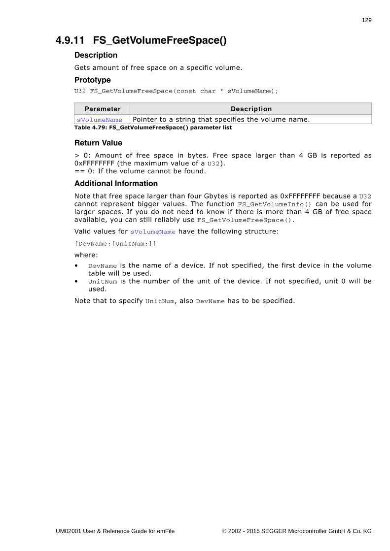
129
4.9.11 FS_GetVolumeFreeSpace()Description
Gets amount of free space on a specific volume.
PrototypeU32 FS_GetVolumeFreeSpace(const char * sVolumeName);
Return Value
> 0: Amount of free space in bytes. Free space larger than 4 GB is reported as0xFFFFFFFF (the maximum value of a U32). == 0: If the volume cannot be found.
Additional Information
Note that free space larger than four Gbytes is reported as 0xFFFFFFFF because a U32cannot represent bigger values. The function FS_GetVolumeInfo() can be used forlarger spaces. If you do not need to know if there is more than 4 GB of free spaceavailable, you can still reliably use FS_GetVolumeFreeSpace().
Valid values for sVolumeName have the following structure:
[DevName:[UnitNum:]]
where:
� DevName is the name of a device. If not specified, the first device in the volumetable will be used.
� UnitNum is the number of the unit of the device. If not specified, unit 0 will beused.
Note that to specify UnitNum, also DevName has to be specified.
Parameter Description
sVolumeName Pointer to a string that specifies the volume name.Table 4.79: FS_GetVolumeFreeSpace() parameter list
UM02001 User & Reference Guide for emFile © 2002 - 2015 SEGGER Microcontroller GmbH & Co. KG
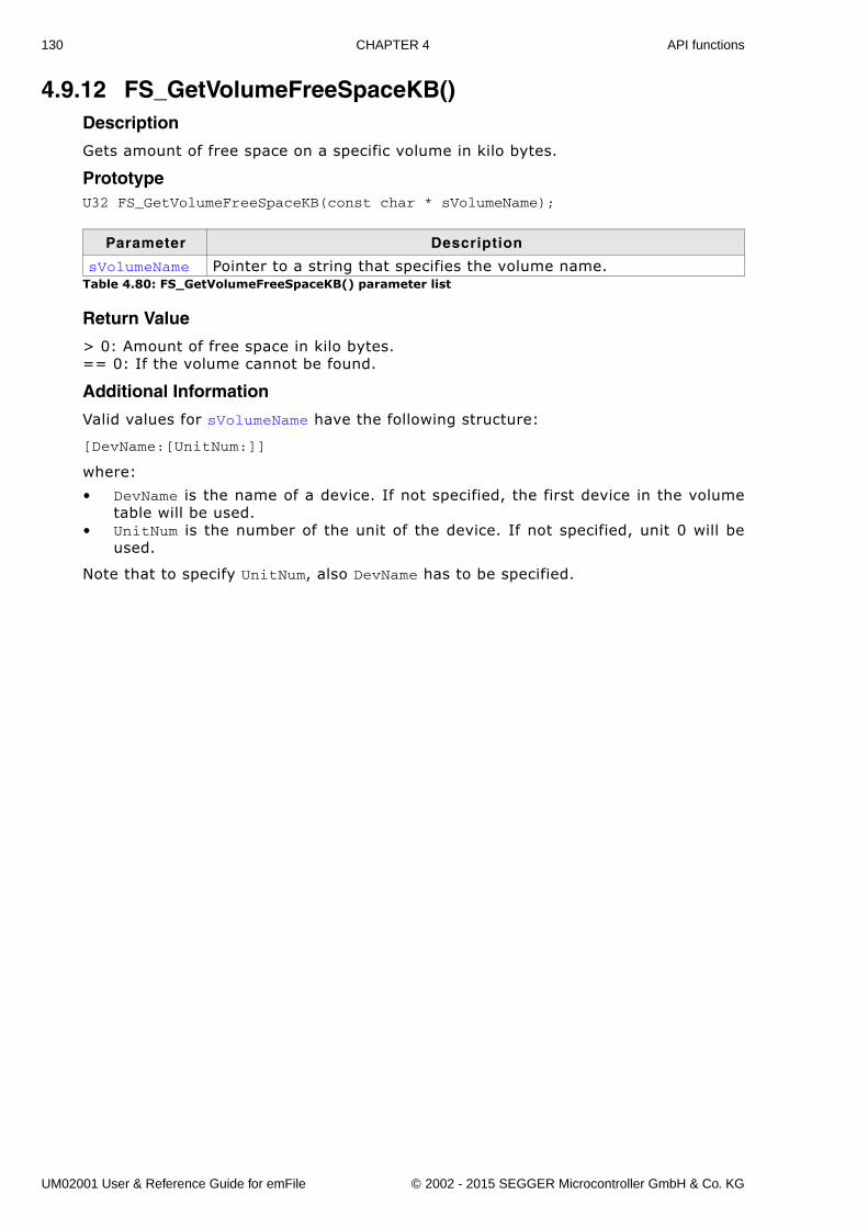
130 CHAPTER 4 API functions
4.9.12 FS_GetVolumeFreeSpaceKB()Description
Gets amount of free space on a specific volume in kilo bytes.
PrototypeU32 FS_GetVolumeFreeSpaceKB(const char * sVolumeName);
Return Value
> 0: Amount of free space in kilo bytes. == 0: If the volume cannot be found.
Additional Information
Valid values for sVolumeName have the following structure:
[DevName:[UnitNum:]]
where:
� DevName is the name of a device. If not specified, the first device in the volumetable will be used.
� UnitNum is the number of the unit of the device. If not specified, unit 0 will beused.
Note that to specify UnitNum, also DevName has to be specified.
Parameter Description
sVolumeName Pointer to a string that specifies the volume name.Table 4.80: FS_GetVolumeFreeSpaceKB() parameter list
UM02001 User & Reference Guide for emFile © 2002 - 2015 SEGGER Microcontroller GmbH & Co. KG
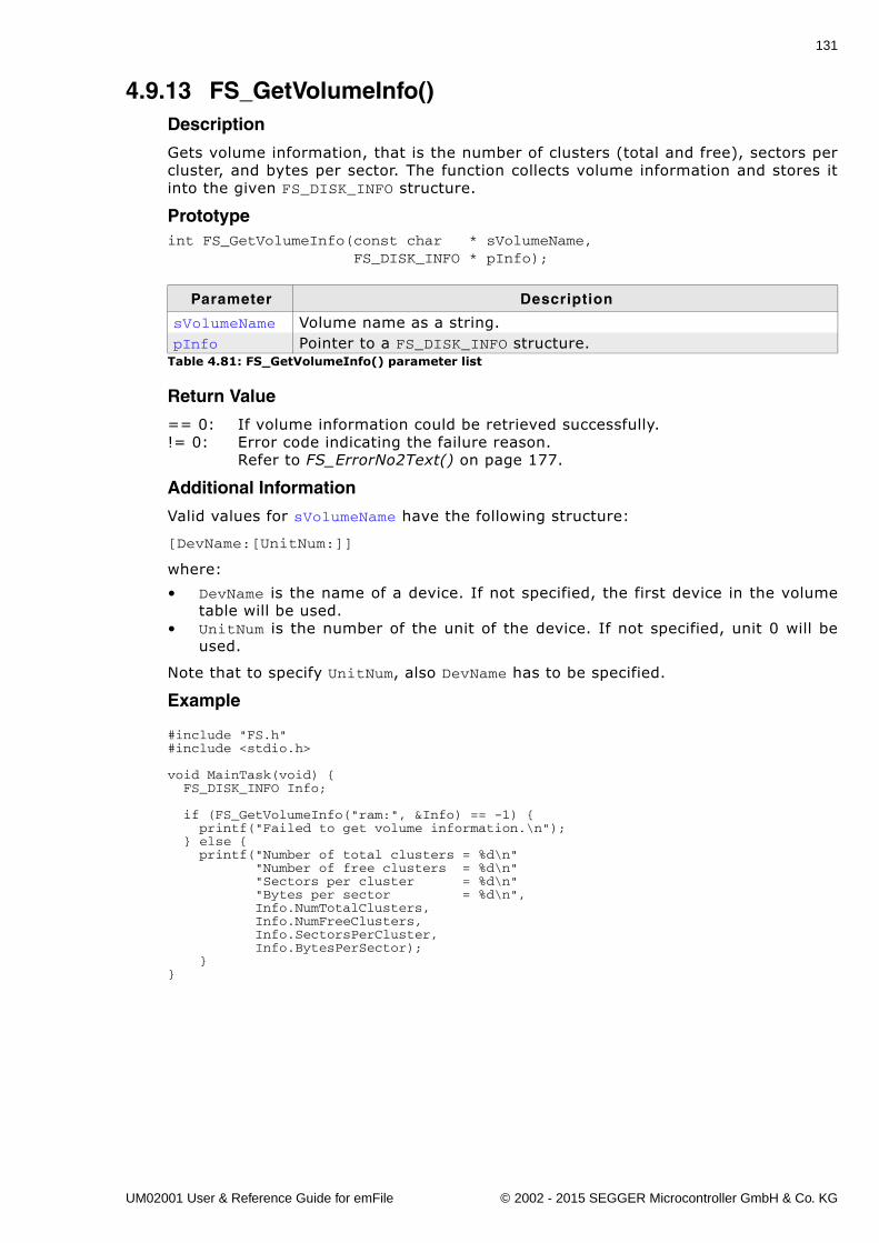
131
4.9.13 FS_GetVolumeInfo()Description
Gets volume information, that is the number of clusters (total and free), sectors percluster, and bytes per sector. The function collects volume information and stores itinto the given FS_DISK_INFO structure.
Prototypeint FS_GetVolumeInfo(const char * sVolumeName, FS_DISK_INFO * pInfo);
Return Value
== 0: If volume information could be retrieved successfully.!= 0: Error code indicating the failure reason.
Refer to FS_ErrorNo2Text() on page 177.
Additional Information
Valid values for sVolumeName have the following structure:
[DevName:[UnitNum:]]
where:
� DevName is the name of a device. If not specified, the first device in the volumetable will be used.
� UnitNum is the number of the unit of the device. If not specified, unit 0 will beused.
Note that to specify UnitNum, also DevName has to be specified.
Example
#include "FS.h"#include <stdio.h>
void MainTask(void) { FS_DISK_INFO Info;
if (FS_GetVolumeInfo("ram:", &Info) == -1) { printf("Failed to get volume information.\n"); } else { printf("Number of total clusters = %d\n" "Number of free clusters = %d\n" "Sectors per cluster = %d\n" "Bytes per sector = %d\n", Info.NumTotalClusters, Info.NumFreeClusters, Info.SectorsPerCluster, Info.BytesPerSector); }}
Parameter Description
sVolumeName Volume name as a string.pInfo Pointer to a FS_DISK_INFO structure.
Table 4.81: FS_GetVolumeInfo() parameter list
UM02001 User & Reference Guide for emFile © 2002 - 2015 SEGGER Microcontroller GmbH & Co. KG
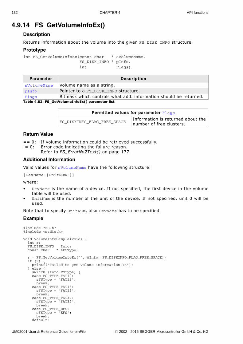
132 CHAPTER 4 API functions
4.9.14 FS_GetVolumeInfoEx()Description
Returns information about the volume into the given FS_DISK_INFO structure.
Prototypeint FS_GetVolumeInfoEx(const char * sVolumeName, FS_DISK_INFO * pInfo,
int Flags);
Return Value
== 0: If volume information could be retrieved successfully.!= 0: Error code indicating the failure reason.
Refer to FS_ErrorNo2Text() on page 177.
Additional Information
Valid values for sVolumeName have the following structure:
[DevName:[UnitNum:]]
where:
� DevName is the name of a device. If not specified, the first device in the volumetable will be used.
� UnitNum is the number of the unit of the device. If not specified, unit 0 will beused.
Note that to specify UnitNum, also DevName has to be specified.
Example
#include "FS.h"#include <stdio.h>
void VolumeInfoSample(void) { int r; FS_DISK_INFO Info; const char * sFSType;
r = FS_GetVolumeInfoEx("", &Info, FS_DISKINFO_FLAG_FREE_SPACE); if (r) { printf("Failed to get volume information.\n"); } else { switch (Info.FSType) { case FS_TYPE_FAT12: sFSType = "FAT12"; break; case FS_TYPE_FAT16: sFSType = "FAT16"; break; case FS_TYPE_FAT32: sFSType = "FAT32"; break; case FS_TYPE_EFS: sFSType = "EFS"; break; default:
Parameter Description
sVolumeName Volume name as a string.pInfo Pointer to a FS_DISK_INFO structure.Flags Bitmask which controls what add. information should be returned.
Table 4.82: FS_GetVolumeInfoEx() parameter list
Permitted values for parameter Flags
FS_DISKINFO_FLAG_FREE_SPACEInformation is returned about the number of free clusters.
UM02001 User & Reference Guide for emFile © 2002 - 2015 SEGGER Microcontroller GmbH & Co. KG
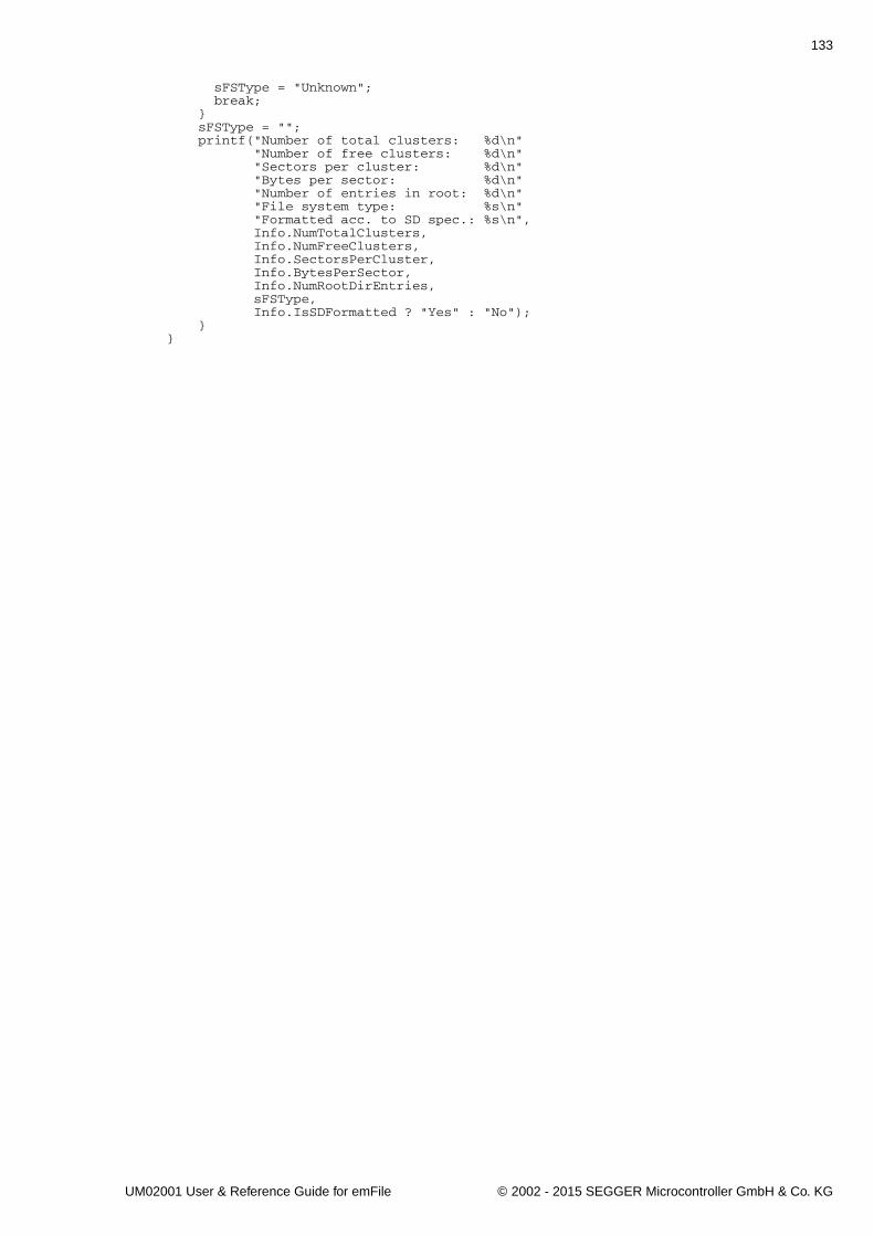
133
sFSType = "Unknown"; break; } sFSType = ""; printf("Number of total clusters: %d\n" "Number of free clusters: %d\n" "Sectors per cluster: %d\n" "Bytes per sector: %d\n" "Number of entries in root: %d\n" "File system type: %s\n" "Formatted acc. to SD spec.: %s\n", Info.NumTotalClusters, Info.NumFreeClusters, Info.SectorsPerCluster, Info.BytesPerSector, Info.NumRootDirEntries, sFSType, Info.IsSDFormatted ? "Yes" : "No"); }}
UM02001 User & Reference Guide for emFile © 2002 - 2015 SEGGER Microcontroller GmbH & Co. KG
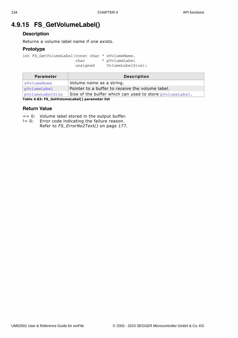
134 CHAPTER 4 API functions
4.9.15 FS_GetVolumeLabel()Description
Returns a volume label name if one exists.
Prototypeint FS_GetVolumeLabel(const char * sVolumeName, char * pVolumeLabel unsigned VolumeLabelSize);
Return Value
== 0: Volume label stored in the output buffer.!= 0: Error code indicating the failure reason.
Refer to FS_ErrorNo2Text() on page 177.
Parameter Description
sVolumeName Volume name as a string.pVolumeLabel Pointer to a buffer to receive the volume label.pVolumeLabelSize Size of the buffer which can used to store pVolumeLabel.
Table 4.83: FS_GetVolumeLabel() parameter list
UM02001 User & Reference Guide for emFile © 2002 - 2015 SEGGER Microcontroller GmbH & Co. KG
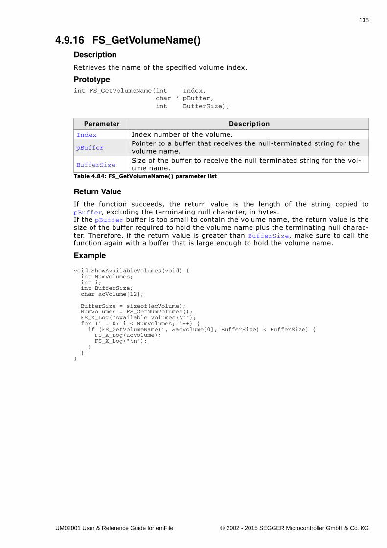
135
4.9.16 FS_GetVolumeName()Description
Retrieves the name of the specified volume index.
Prototypeint FS_GetVolumeName(int Index, char * pBuffer, int BufferSize);
Return Value
If the function succeeds, the return value is the length of the string copied topBuffer, excluding the terminating null character, in bytes.If the pBuffer buffer is too small to contain the volume name, the return value is thesize of the buffer required to hold the volume name plus the terminating null charac-ter. Therefore, if the return value is greater than BufferSize, make sure to call thefunction again with a buffer that is large enough to hold the volume name.
Example
void ShowAvailableVolumes(void) { int NumVolumes; int i; int BufferSize; char acVolume[12];
BufferSize = sizeof(acVolume); NumVolumes = FS_GetNumVolumes(); FS_X_Log("Available volumes:\n"); for (i = 0; i < NumVolumes; i++) { if (FS_GetVolumeName(i, &acVolume[0], BufferSize) < BufferSize) { FS_X_Log(acVolume); FS_X_Log("\n"); } }}
Parameter Description
Index Index number of the volume.
pBufferPointer to a buffer that receives the null-terminated string for the volume name.
BufferSizeSize of the buffer to receive the null terminated string for the vol-ume name.
Table 4.84: FS_GetVolumeName() parameter list
UM02001 User & Reference Guide for emFile © 2002 - 2015 SEGGER Microcontroller GmbH & Co. KG
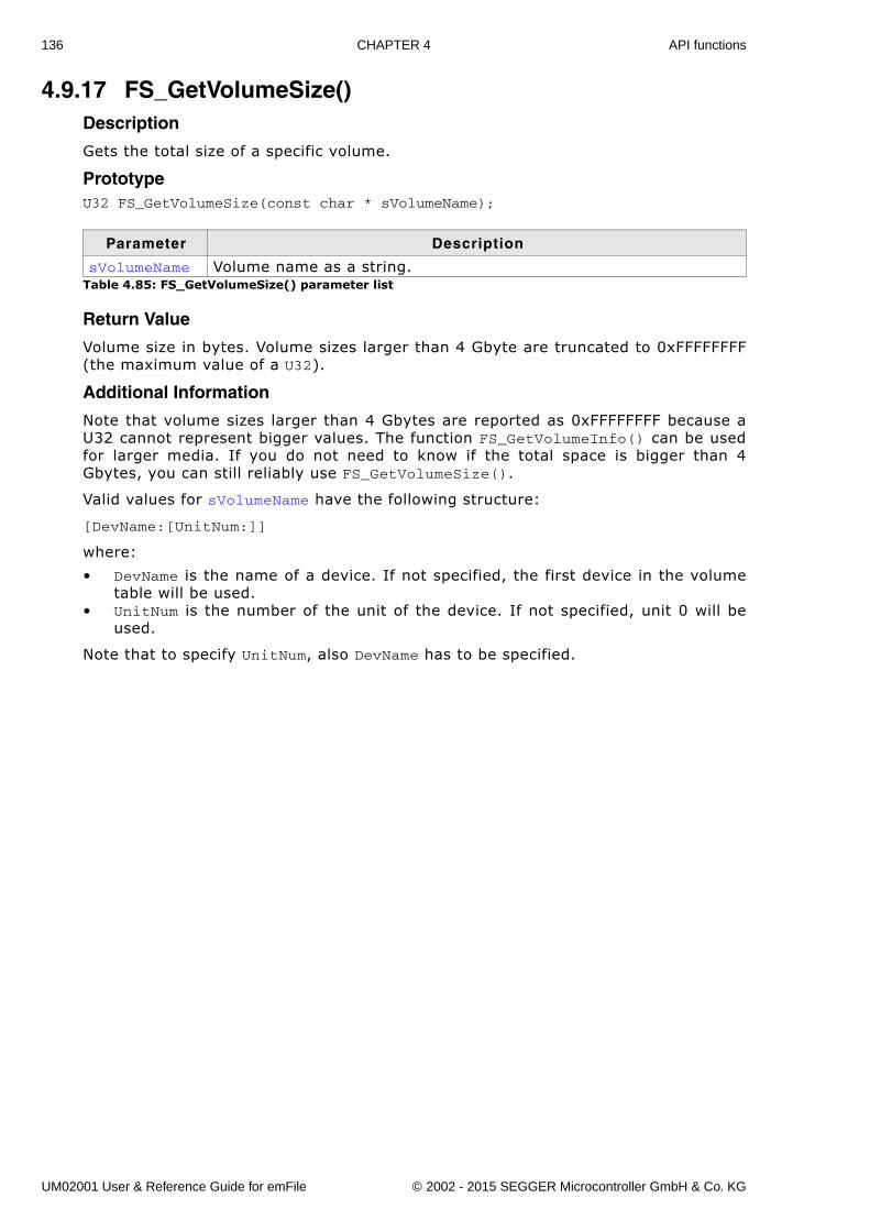
136 CHAPTER 4 API functions
4.9.17 FS_GetVolumeSize()Description
Gets the total size of a specific volume.
PrototypeU32 FS_GetVolumeSize(const char * sVolumeName);
Return Value
Volume size in bytes. Volume sizes larger than 4 Gbyte are truncated to 0xFFFFFFFF(the maximum value of a U32).
Additional Information
Note that volume sizes larger than 4 Gbytes are reported as 0xFFFFFFFF because aU32 cannot represent bigger values. The function FS_GetVolumeInfo() can be usedfor larger media. If you do not need to know if the total space is bigger than 4Gbytes, you can still reliably use FS_GetVolumeSize().
Valid values for sVolumeName have the following structure:
[DevName:[UnitNum:]]
where:
� DevName is the name of a device. If not specified, the first device in the volumetable will be used.
� UnitNum is the number of the unit of the device. If not specified, unit 0 will beused.
Note that to specify UnitNum, also DevName has to be specified.
Parameter Description
sVolumeName Volume name as a string.Table 4.85: FS_GetVolumeSize() parameter list
UM02001 User & Reference Guide for emFile © 2002 - 2015 SEGGER Microcontroller GmbH & Co. KG
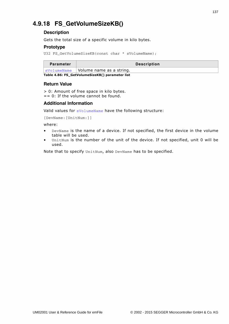
137
4.9.18 FS_GetVolumeSizeKB()Description
Gets the total size of a specific volume in kilo bytes.
PrototypeU32 FS_GetVolumeSizeKB(const char * sVolumeName);
Return Value
> 0: Amount of free space in kilo bytes. == 0: If the volume cannot be found.
Additional Information
Valid values for sVolumeName have the following structure:
[DevName:[UnitNum:]]
where:
� DevName is the name of a device. If not specified, the first device in the volumetable will be used.
� UnitNum is the number of the unit of the device. If not specified, unit 0 will beused.
Note that to specify UnitNum, also DevName has to be specified.
Parameter Description
sVolumeName Volume name as a string.Table 4.86: FS_GetVolumeSizeKB() parameter list
UM02001 User & Reference Guide for emFile © 2002 - 2015 SEGGER Microcontroller GmbH & Co. KG
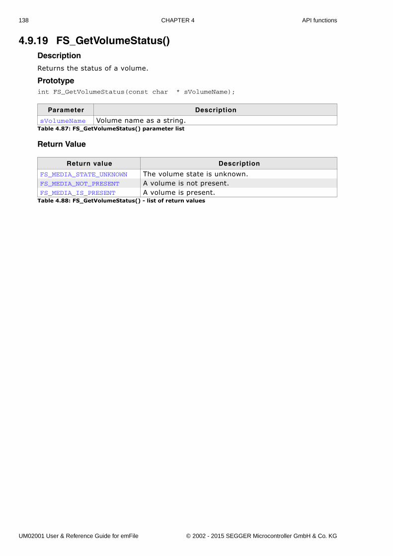
138 CHAPTER 4 API functions
4.9.19 FS_GetVolumeStatus()Description
Returns the status of a volume.
Prototypeint FS_GetVolumeStatus(const char * sVolumeName);
Return Value
Parameter Description
sVolumeName Volume name as a string.Table 4.87: FS_GetVolumeStatus() parameter list
Return value Description
FS_MEDIA_STATE_UNKNOWN The volume state is unknown.FS_MEDIA_NOT_PRESENT A volume is not present.FS_MEDIA_IS_PRESENT A volume is present.
Table 4.88: FS_GetVolumeStatus() - list of return values
UM02001 User & Reference Guide for emFile © 2002 - 2015 SEGGER Microcontroller GmbH & Co. KG
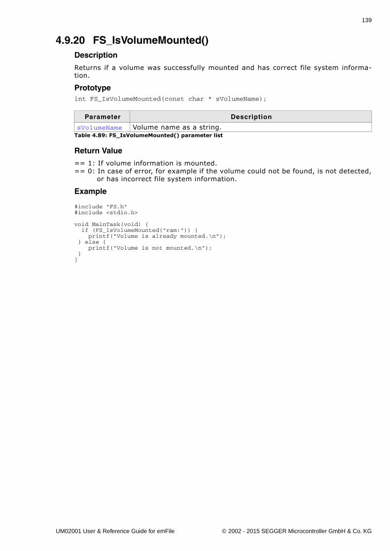
139
4.9.20 FS_IsVolumeMounted()Description
Returns if a volume was successfully mounted and has correct file system informa-tion.
Prototypeint FS_IsVolumeMounted(const char * sVolumeName);
Return Value
== 1: If volume information is mounted.== 0: In case of error, for example if the volume could not be found, is not detected, or has incorrect file system information.
Example
#include "FS.h"#include <stdio.h>
void MainTask(void) { if (FS_IsVolumeMounted("ram:")) { printf("Volume is already mounted.\n"); } else { printf("Volume is not mounted.\n"); }}
Parameter Description
sVolumeName Volume name as a string.Table 4.89: FS_IsVolumeMounted() parameter list
UM02001 User & Reference Guide for emFile © 2002 - 2015 SEGGER Microcontroller GmbH & Co. KG
140 CHAPTER 4 API functions
4.9.21 FS_Lock()Description
Claims the exclusive access to file system.
Prototypevoid FS_Lock(void);
Additional information
The execution of the task that calls this function is suspended until the exclusiveaccess to file system can be granted. Typically used by an application when driverspecific functions are called from different tasks. These functions are usually not pro-tected against concurrent accesses. No other task can perform file system operationsuntil FS_Unlock() is called. If FS_OS_LOCKING is not set to 1, the function does noth-ing.
Note: The file system API functions are multitasking safe. Explicit locking usingFS_Lock()/FS_Unlock() is not required.
UM02001 User & Reference Guide for emFile © 2002 - 2015 SEGGER Microcontroller GmbH & Co. KG
141
4.9.22 FS_LockVolume()Description
Claims the exclusive access to a given volume.
Prototypevoid FS_LockVolume(const char * sVolumeName);
Additional information
The execution of the task that calls this function is suspended until the exclusiveaccess to file system can be granted. If FS_OS_LOCKING is not set to 2, the functiondoes nothing.
Note: The file system API functions are multitasking safe. Explicit locking usingFS_LockVolume()/FS_UnlockVolume() is not required.
Parameter Description
sVolumeName Volume name as a string.
UM02001 User & Reference Guide for emFile © 2002 - 2015 SEGGER Microcontroller GmbH & Co. KG
142 CHAPTER 4 API functions
4.9.23 FS_SetBusyLEDCallback()Description
Specifies callback function to control an LED which shows the state of a specific vol-ume.
Prototypevoid FS_SetBusyLEDCallback(const char * sVolumeName, FS_BUSY_LED_CALLBACK * pfBusyLEDCallback);
Additional Information
If you intend to show any volume read/write activity, use this function to set the busyindication for the desired volume.
Example
#include "FS.h"
static void _cbBusyLED(U8 OnOff) { if (OnOff) { HW_SetLED(); } else { HW_ClrLED(); }}
void MainTask(void) { FS_FILE * pFile;
FS_Init(); FS_SetBusyLEDCallback(“ram:”, _cbBusyLED); pFile = FS_FOpen(“ram:\\file.txt“, “w“); FS_FClose(pFile);}
Parameter Description
sVolumeName Volume name as a string.
pfBusyLEDCallbackCallback function which is invoked when the LED status should be changed.
Table 4.90: FS_SetBusyLEDCallback() parameter list
UM02001 User & Reference Guide for emFile © 2002 - 2015 SEGGER Microcontroller GmbH & Co. KG
143
4.9.24 FS_SetMemAccessCallback()Description
Registers a function which should be called before any read and write operation tocheck if a data buffer can be used in 0-copy operation.
Prototypevoid FS_SetMemAccessCallback(const char * sVolumeName, FS_MEMORY_IS_ACCESSIBLE_CALLBACK * pfIsAccessibleCallback);
Additional Information
This function is available only if the sources are compiled with theFS_SUPPORT_CHECK_MEMORY switch is set to 1. The file system operations are opti-mized to avoid the copying of data being written or read. Where possible, 0-copyoperations are used. Only a pointer to data being written or read is passed betweenthe file system layers. By registering a callback function an application can controlwhether a 0-copy operation is allowed or not. This can be useful, for example, if theHW layer uses DMA to transfer the data and the DMA controller can not access a cer-tain memory region. In such a case the callback should return 0 to inform the filesystem to buffer the data internally.
Example
#include "FS.h"
static int _cbIsMemoryAccessible(void * p, U32 NumBytes) { if ((U32)p > 0x100000uL) { return 1; // 0-copy allowed. } else { return 0; // 0-copy not allowed }}
void MainTask(void) { FS_FILE * pFile;
FS_Init(); FS_SetMemAccessCallback(“ram:”, _cbIsMemoryAccessible); pFile = FS_FOpen(“ram:\\file.txt“, “w“); if (pFile) { FS_FWrite(“Test\n“, 5, 1, pFile); } FS_FClose(pFile);}
Parameter Description
sVolumeName Volume name as a string.pfIsAccessibleCallback Pointer to a function which performs the checking.
Table 4.91: FS_SetMemAccessCallback() parameter list
UM02001 User & Reference Guide for emFile © 2002 - 2015 SEGGER Microcontroller GmbH & Co. KG
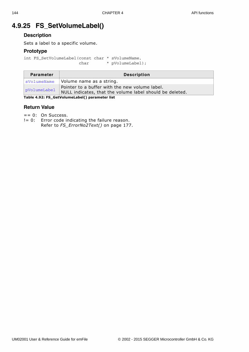
144 CHAPTER 4 API functions
4.9.25 FS_SetVolumeLabel()Description
Sets a label to a specific volume.
Prototypeint FS_SetVolumeLabel(const char * sVolumeName, char * pVolumeLabel);
Return Value
== 0: On Success.!= 0: Error code indicating the failure reason.
Refer to FS_ErrorNo2Text() on page 177.
Parameter Description
sVolumeName Volume name as a string.
pVolumeLabelPointer to a buffer with the new volume label.NULL indicates, that the volume label should be deleted.
Table 4.92: FS_GetVolumeLabel() parameter list
UM02001 User & Reference Guide for emFile © 2002 - 2015 SEGGER Microcontroller GmbH & Co. KG
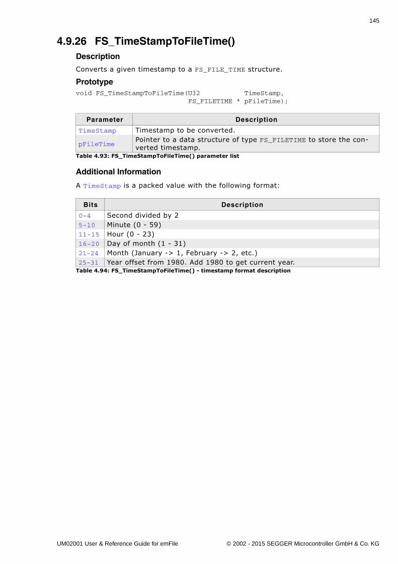
145
4.9.26 FS_TimeStampToFileTime()Description
Converts a given timestamp to a FS_FILE_TIME structure.
Prototypevoid FS_TimeStampToFileTime(U32 TimeStamp, FS_FILETIME * pFileTime);
Additional Information
A TimeStamp is a packed value with the following format:
Parameter Description
TimeStamp Timestamp to be converted.
pFileTimePointer to a data structure of type FS_FILETIME to store the con-verted timestamp.
Table 4.93: FS_TimeStampToFileTime() parameter list
Bits Description
0-4 Second divided by 25-10 Minute (0 - 59)11-15 Hour (0 - 23)16-20 Day of month (1 - 31)21-24 Month (January -> 1, February -> 2, etc.)25-31 Year offset from 1980. Add 1980 to get current year.
Table 4.94: FS_TimeStampToFileTime() - timestamp format description
UM02001 User & Reference Guide for emFile © 2002 - 2015 SEGGER Microcontroller GmbH & Co. KG
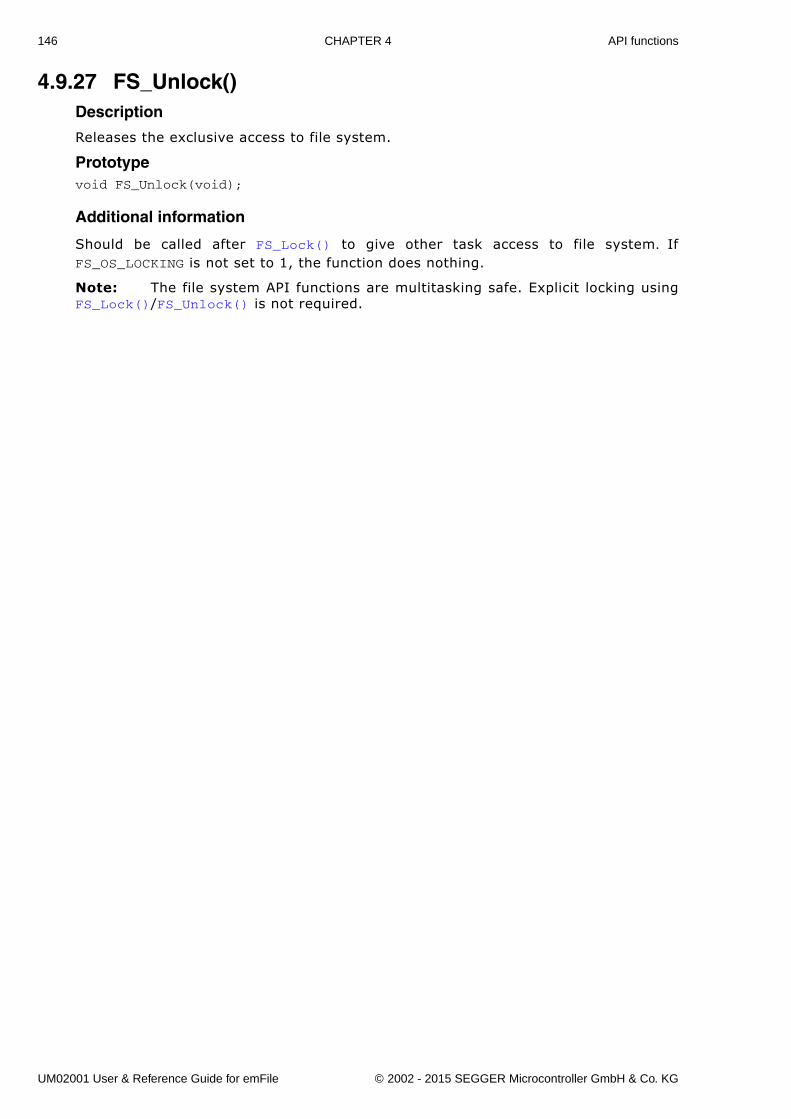
146 CHAPTER 4 API functions
4.9.27 FS_Unlock()Description
Releases the exclusive access to file system.
Prototypevoid FS_Unlock(void);
Additional information
Should be called after FS_Lock() to give other task access to file system. IfFS_OS_LOCKING is not set to 1, the function does nothing.
Note: The file system API functions are multitasking safe. Explicit locking usingFS_Lock()/FS_Unlock() is not required.
UM02001 User & Reference Guide for emFile © 2002 - 2015 SEGGER Microcontroller GmbH & Co. KG
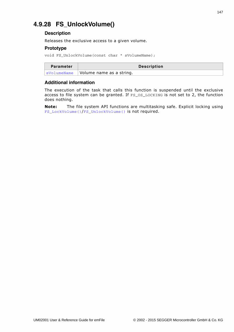
147
4.9.28 FS_UnlockVolume()Description
Releases the exclusive access to a given volume.
Prototypevoid FS_UnlockVolume(const char * sVolumeName);
Additional information
The execution of the task that calls this function is suspended until the exclusiveaccess to file system can be granted. If FS_OS_LOCKING is not set to 2, the functiondoes nothing.
Note: The file system API functions are multitasking safe. Explicit locking usingFS_LockVolume()/FS_UnlockVolume() is not required.
Parameter Description
sVolumeName Volume name as a string.
UM02001 User & Reference Guide for emFile © 2002 - 2015 SEGGER Microcontroller GmbH & Co. KG
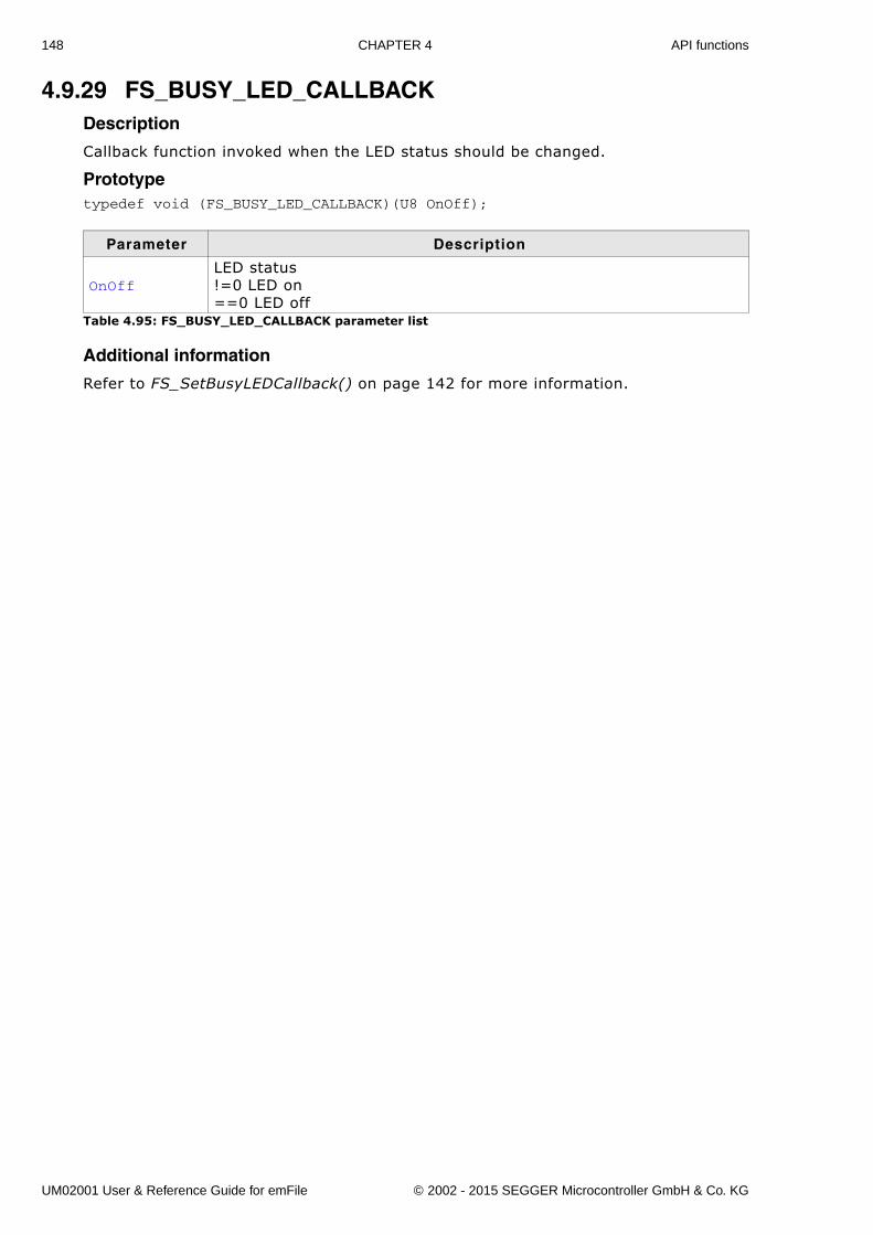
148 CHAPTER 4 API functions
4.9.29 FS_BUSY_LED_CALLBACKDescription
Callback function invoked when the LED status should be changed.
Prototypetypedef void (FS_BUSY_LED_CALLBACK)(U8 OnOff);
Additional information
Refer to FS_SetBusyLEDCallback() on page 142 for more information.
Parameter Description
OnOffLED status!=0 LED on==0 LED off
Table 4.95: FS_BUSY_LED_CALLBACK parameter list
UM02001 User & Reference Guide for emFile © 2002 - 2015 SEGGER Microcontroller GmbH & Co. KG
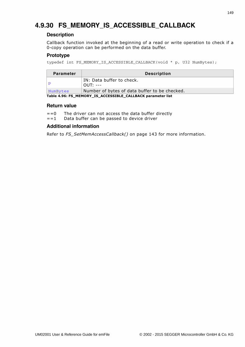
149
4.9.30 FS_MEMORY_IS_ACCESSIBLE_CALLBACKDescription
Callback function invoked at the beginning of a read or write operation to check if a0-copy operation can be performed on the data buffer.
Prototypetypedef int FS_MEMORY_IS_ACCESSIBLE_CALLBACK(void * p, U32 NumBytes);
Return value
==0 The driver can not access the data buffer directly==1 Data buffer can be passed to device driver
Additional information
Refer to FS_SetMemAccessCallback() on page 143 for more information.
Parameter Description
pIN: Data buffer to check.OUT: ---
NumBytes Number of bytes of data buffer to be checked.Table 4.96: FS_MEMORY_IS_ACCESSIBLE_CALLBACK parameter list
UM02001 User & Reference Guide for emFile © 2002 - 2015 SEGGER Microcontroller GmbH & Co. KG
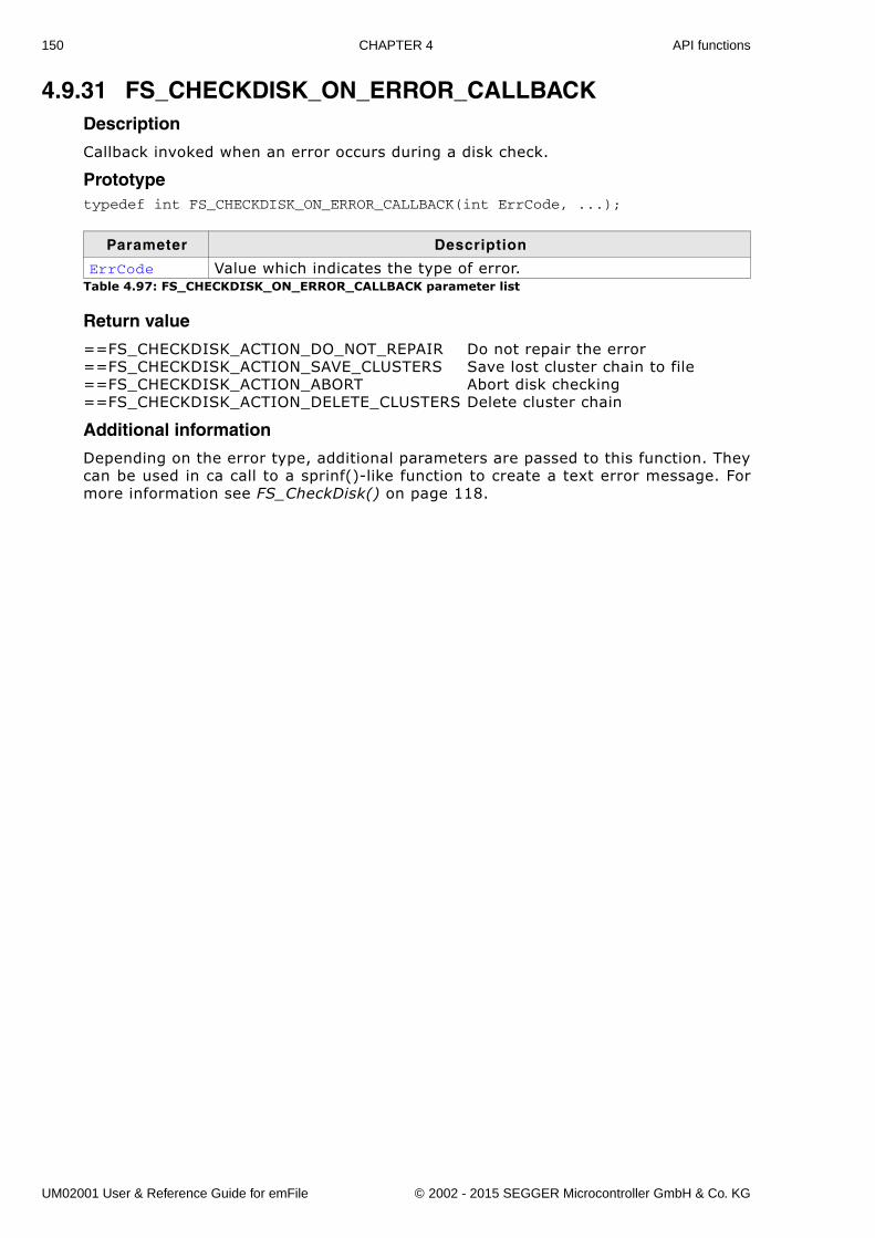
150 CHAPTER 4 API functions
4.9.31 FS_CHECKDISK_ON_ERROR_CALLBACKDescription
Callback invoked when an error occurs during a disk check.
Prototypetypedef int FS_CHECKDISK_ON_ERROR_CALLBACK(int ErrCode, ...);
Return value
==FS_CHECKDISK_ACTION_DO_NOT_REPAIR Do not repair the error==FS_CHECKDISK_ACTION_SAVE_CLUSTERS Save lost cluster chain to file==FS_CHECKDISK_ACTION_ABORT Abort disk checking==FS_CHECKDISK_ACTION_DELETE_CLUSTERS Delete cluster chain
Additional information
Depending on the error type, additional parameters are passed to this function. Theycan be used in ca call to a sprinf()-like function to create a text error message. Formore information see FS_CheckDisk() on page 118.
Parameter Description
ErrCode Value which indicates the type of error.Table 4.97: FS_CHECKDISK_ON_ERROR_CALLBACK parameter list
UM02001 User & Reference Guide for emFile © 2002 - 2015 SEGGER Microcontroller GmbH & Co. KG
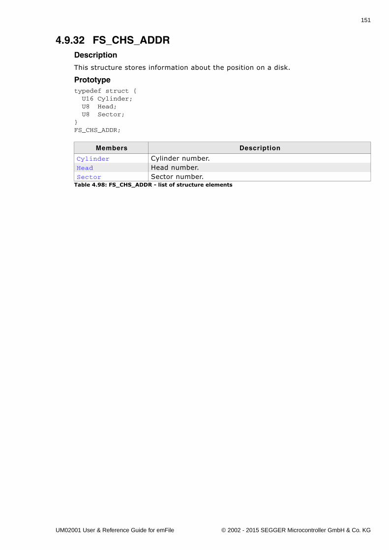
151
4.9.32 FS_CHS_ADDRDescription
This structure stores information about the position on a disk.
Prototypetypedef struct { U16 Cylinder; U8 Head; U8 Sector;}FS_CHS_ADDR;
Members Description
Cylinder Cylinder number.Head Head number.Sector Sector number.
Table 4.98: FS_CHS_ADDR - list of structure elements
UM02001 User & Reference Guide for emFile © 2002 - 2015 SEGGER Microcontroller GmbH & Co. KG
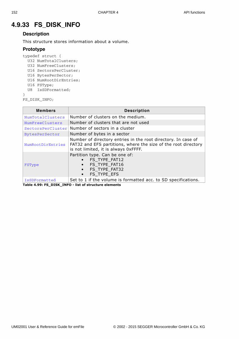
152 CHAPTER 4 API functions
4.9.33 FS_DISK_INFODescription
This structure stores information about a volume.
Prototypetypedef struct { U32 NumTotalClusters; U32 NumFreeClusters; U16 SectorsPerCluster; U16 BytesPerSector; U16 NumRootDirEntries; U16 FSType; U8 IsSDFormatted;}FS_DISK_INFO;
Members Description
NumTotalClusters Number of clusters on the medium.NumFreeClusters Number of clusters that are not usedSectorsPerCluster Number of sectors in a clusterBytesPerSector Number of bytes in a sector
NumRootDirEntriesNumber of directory entries in the root directory. In case of FAT32 and EFS partitions, where the size of the root directory is not limited, it is always 0xFFFF.
FSType
Partition type. Can be one of:� FS_TYPE_FAT12� FS_TYPE_FAT16� FS_TYPE_FAT32� FS_TYPE_EFS
IsSDFormatted Set to 1 if the volume is formatted acc. to SD specifications.Table 4.99: FS_DISK_INFO - list of structure elements
UM02001 User & Reference Guide for emFile © 2002 - 2015 SEGGER Microcontroller GmbH & Co. KG
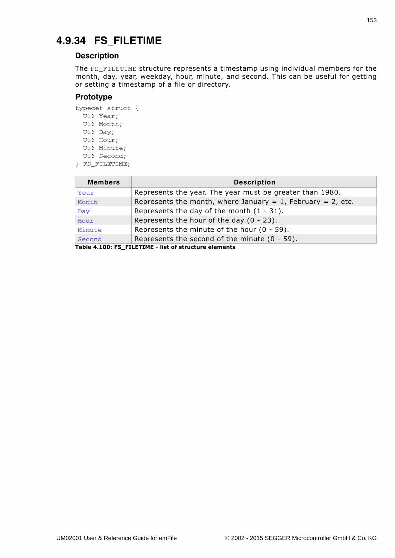
153
4.9.34 FS_FILETIMEDescription
The FS_FILETIME structure represents a timestamp using individual members for themonth, day, year, weekday, hour, minute, and second. This can be useful for gettingor setting a timestamp of a file or directory.
Prototypetypedef struct { U16 Year; U16 Month; U16 Day; U16 Hour; U16 Minute; U16 Second;} FS_FILETIME;
Members Description
Year Represents the year. The year must be greater than 1980.Month Represents the month, where January = 1, February = 2, etc.Day Represents the day of the month (1 - 31).Hour Represents the hour of the day (0 - 23).Minute Represents the minute of the hour (0 - 59).Second Represents the second of the minute (0 - 59).
Table 4.100: FS_FILETIME - list of structure elements
UM02001 User & Reference Guide for emFile © 2002 - 2015 SEGGER Microcontroller GmbH & Co. KG
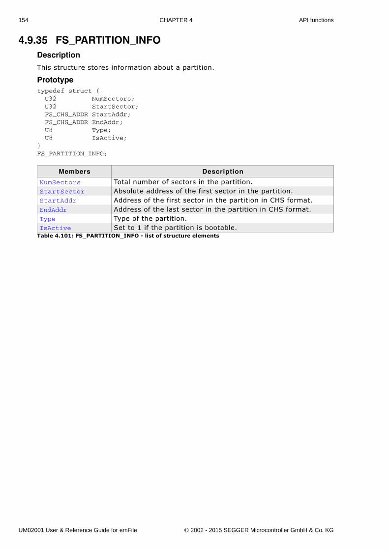
154 CHAPTER 4 API functions
4.9.35 FS_PARTITION_INFODescription
This structure stores information about a partition.
Prototypetypedef struct { U32 NumSectors; U32 StartSector; FS_CHS_ADDR StartAddr; FS_CHS_ADDR EndAddr; U8 Type; U8 IsActive;}FS_PARTITION_INFO;
Members Description
NumSectors Total number of sectors in the partition.StartSector Absolute address of the first sector in the partition.StartAddr Address of the first sector in the partition in CHS format.EndAddr Address of the last sector in the partition in CHS format.Type Type of the partition.IsActive Set to 1 if the partition is bootable.
Table 4.101: FS_PARTITION_INFO - list of structure elements
UM02001 User & Reference Guide for emFile © 2002 - 2015 SEGGER Microcontroller GmbH & Co. KG
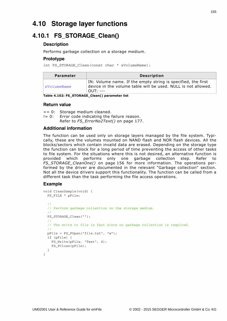
155
4.10 Storage layer functions
4.10.1 FS_STORAGE_Clean()Description
Performs garbage collection on a storage medium.
Prototypeint FS_STORAGE_Clean(const char * sVolumeName);
Return value
== 0: Storage medium cleaned.!= 0: Error code indicating the failure reason.
Refer to FS_ErrorNo2Text() on page 177.
Additional information
The function can be used only on storage layers managed by the file system. Typi-cally, these are the volumes mounted on NAND flash and NOR flash devices. All theblocks/sectors which contain invalid data are erased. Depending on the storage typethe function can block for a long period of time preventing the access of other tasksto file system. For the situations where this is not desired, an alternative function isprovided which performs only one garbage collection step. Refer toFS_STORAGE_CleanOne() on page 156 for more information. The operations per-formed by the driver are documented in the relevant �Garbage collection� section.Not all the device drivers support this functionality. The function can be called from adifferent task than the task performing the file access operations.
Example
void CleanSample(void) { FS_FILE * pFile;
// // Perform garbage collection on the storage medium. // FS_STORAGE_Clean(""); // // The write to file is fast since no garbage collection is required. // pFile = FS_FOpen("file.txt", "w"); if (pFile) { FS_Write(pFile, "Test", 4); FS_FClose(pFile); }}
Parameter Description
sVolumeNameIN: Volume name. If the empty string is specified, the first device in the volume table will be used. NULL is not allowed.OUT: ---
Table 4.102: FS_STORAGE_Clean() parameter list
UM02001 User & Reference Guide for emFile © 2002 - 2015 SEGGER Microcontroller GmbH & Co. KG
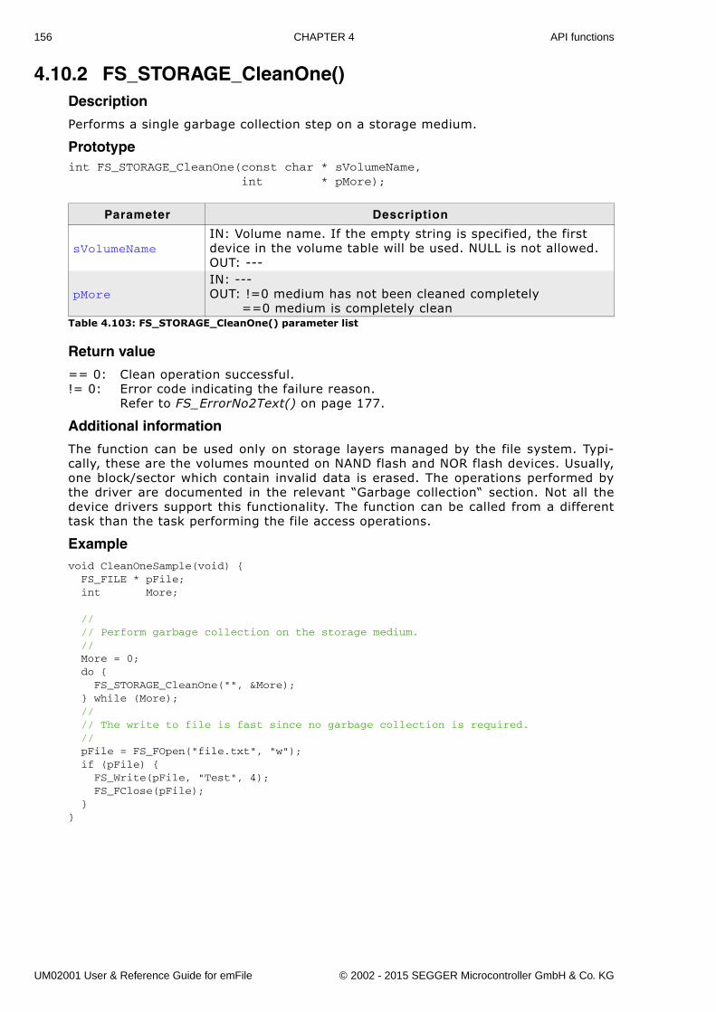
156 CHAPTER 4 API functions
4.10.2 FS_STORAGE_CleanOne()Description
Performs a single garbage collection step on a storage medium.
Prototypeint FS_STORAGE_CleanOne(const char * sVolumeName, int * pMore);
Return value
== 0: Clean operation successful.!= 0: Error code indicating the failure reason.
Refer to FS_ErrorNo2Text() on page 177.
Additional information
The function can be used only on storage layers managed by the file system. Typi-cally, these are the volumes mounted on NAND flash and NOR flash devices. Usually,one block/sector which contain invalid data is erased. The operations performed bythe driver are documented in the relevant �Garbage collection� section. Not all thedevice drivers support this functionality. The function can be called from a differenttask than the task performing the file access operations.
Examplevoid CleanOneSample(void) { FS_FILE * pFile; int More;
// // Perform garbage collection on the storage medium. // More = 0; do { FS_STORAGE_CleanOne("", &More); } while (More); // // The write to file is fast since no garbage collection is required. // pFile = FS_FOpen("file.txt", "w"); if (pFile) { FS_Write(pFile, "Test", 4); FS_FClose(pFile); }}
Parameter Description
sVolumeNameIN: Volume name. If the empty string is specified, the first device in the volume table will be used. NULL is not allowed.OUT: ---
pMoreIN: ---OUT: !=0 medium has not been cleaned completely ==0 medium is completely clean
Table 4.103: FS_STORAGE_CleanOne() parameter list
UM02001 User & Reference Guide for emFile © 2002 - 2015 SEGGER Microcontroller GmbH & Co. KG
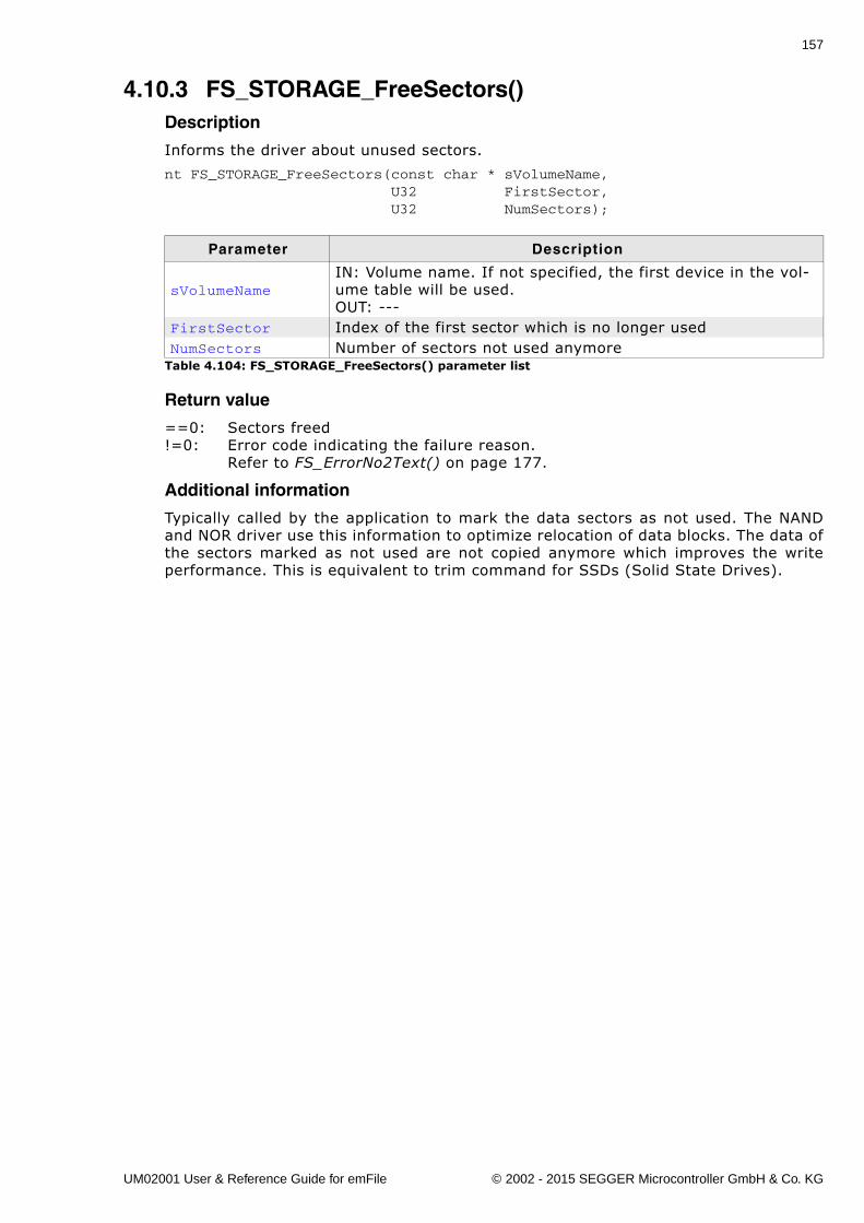
157
4.10.3 FS_STORAGE_FreeSectors()Description
Informs the driver about unused sectors.
nt FS_STORAGE_FreeSectors(const char * sVolumeName, U32 FirstSector, U32 NumSectors);
Return value
==0: Sectors freed!=0: Error code indicating the failure reason.
Refer to FS_ErrorNo2Text() on page 177.
Additional information
Typically called by the application to mark the data sectors as not used. The NANDand NOR driver use this information to optimize relocation of data blocks. The data ofthe sectors marked as not used are not copied anymore which improves the writeperformance. This is equivalent to trim command for SSDs (Solid State Drives).
Parameter Description
sVolumeNameIN: Volume name. If not specified, the first device in the vol-ume table will be used.OUT: ---
FirstSector Index of the first sector which is no longer usedNumSectors Number of sectors not used anymore
Table 4.104: FS_STORAGE_FreeSectors() parameter list
UM02001 User & Reference Guide for emFile © 2002 - 2015 SEGGER Microcontroller GmbH & Co. KG
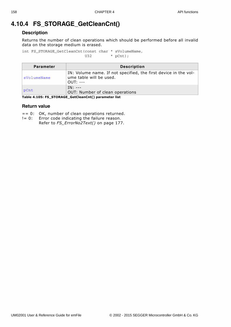
158 CHAPTER 4 API functions
4.10.4 FS_STORAGE_GetCleanCnt()Description
Returns the number of clean operations which should be performed before all invaliddata on the storage medium is erased.
int FS_STORAGE_GetCleanCnt(const char * sVolumeName, U32 * pCnt);
Return value
== 0: OK, number of clean operations returned.!= 0: Error code indicating the failure reason.
Refer to FS_ErrorNo2Text() on page 177.
Parameter Description
sVolumeNameIN: Volume name. If not specified, the first device in the vol-ume table will be used.OUT: ---
pCntIN: ---OUT: Number of clean operations
Table 4.105: FS_STORAGE_GetCleanCnt() parameter list
UM02001 User & Reference Guide for emFile © 2002 - 2015 SEGGER Microcontroller GmbH & Co. KG
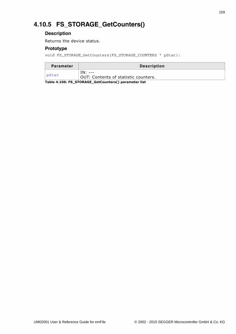
159
4.10.5 FS_STORAGE_GetCounters()Description
Returns the device status.
Prototypevoid FS_STORAGE_GetCounters(FS_STORAGE_COUNTERS * pStat);
Parameter Description
pStatIN: ---OUT: Contents of statistic counters.
Table 4.106: FS_STORAGE_GetCounters() parameter list
UM02001 User & Reference Guide for emFile © 2002 - 2015 SEGGER Microcontroller GmbH & Co. KG
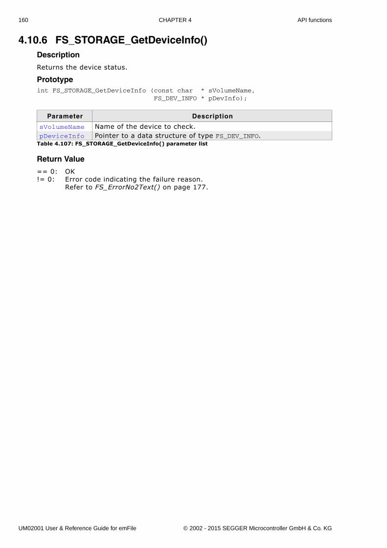
160 CHAPTER 4 API functions
4.10.6 FS_STORAGE_GetDeviceInfo()Description
Returns the device status.
Prototypeint FS_STORAGE_GetDeviceInfo (const char * sVolumeName, FS_DEV_INFO * pDevInfo);
Return Value
== 0: OK!= 0: Error code indicating the failure reason.
Refer to FS_ErrorNo2Text() on page 177.
Parameter Description
sVolumeName Name of the device to check.pDeviceInfo Pointer to a data structure of type FS_DEV_INFO.
Table 4.107: FS_STORAGE_GetDeviceInfo() parameter list
UM02001 User & Reference Guide for emFile © 2002 - 2015 SEGGER Microcontroller GmbH & Co. KG
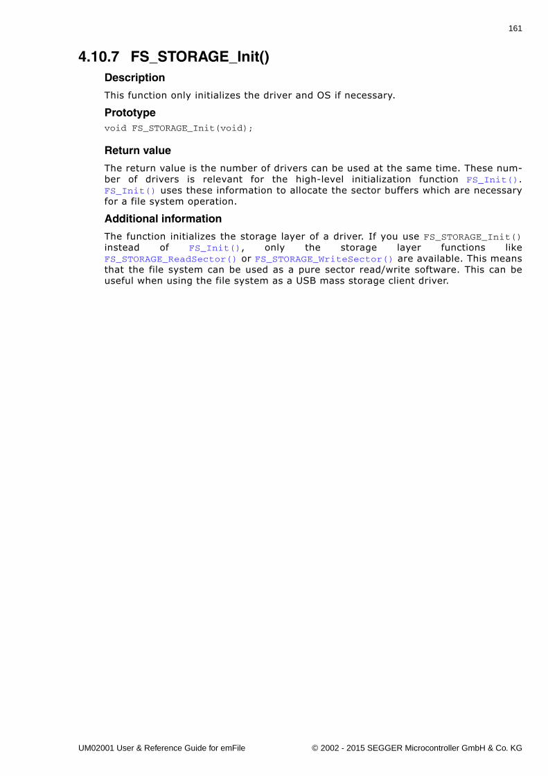
161
4.10.7 FS_STORAGE_Init()Description
This function only initializes the driver and OS if necessary.
Prototypevoid FS_STORAGE_Init(void);
Return value
The return value is the number of drivers can be used at the same time. These num-ber of drivers is relevant for the high-level initialization function FS_Init().FS_Init() uses these information to allocate the sector buffers which are necessaryfor a file system operation.
Additional information
The function initializes the storage layer of a driver. If you use FS_STORAGE_Init()instead of FS_Init(), only the storage layer functions likeFS_STORAGE_ReadSector() or FS_STORAGE_WriteSector() are available. This meansthat the file system can be used as a pure sector read/write software. This can beuseful when using the file system as a USB mass storage client driver.
UM02001 User & Reference Guide for emFile © 2002 - 2015 SEGGER Microcontroller GmbH & Co. KG
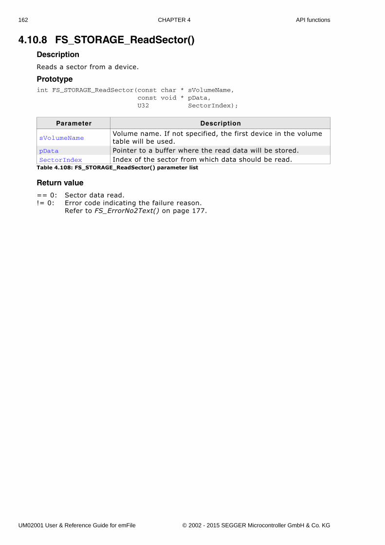
162 CHAPTER 4 API functions
4.10.8 FS_STORAGE_ReadSector()Description
Reads a sector from a device.
Prototypeint FS_STORAGE_ReadSector(const char * sVolumeName, const void * pData, U32 SectorIndex);
Return value
== 0: Sector data read.!= 0: Error code indicating the failure reason.
Refer to FS_ErrorNo2Text() on page 177.
Parameter Description
sVolumeNameVolume name. If not specified, the first device in the volume table will be used.
pData Pointer to a buffer where the read data will be stored.SectorIndex Index of the sector from which data should be read.
Table 4.108: FS_STORAGE_ReadSector() parameter list
UM02001 User & Reference Guide for emFile © 2002 - 2015 SEGGER Microcontroller GmbH & Co. KG
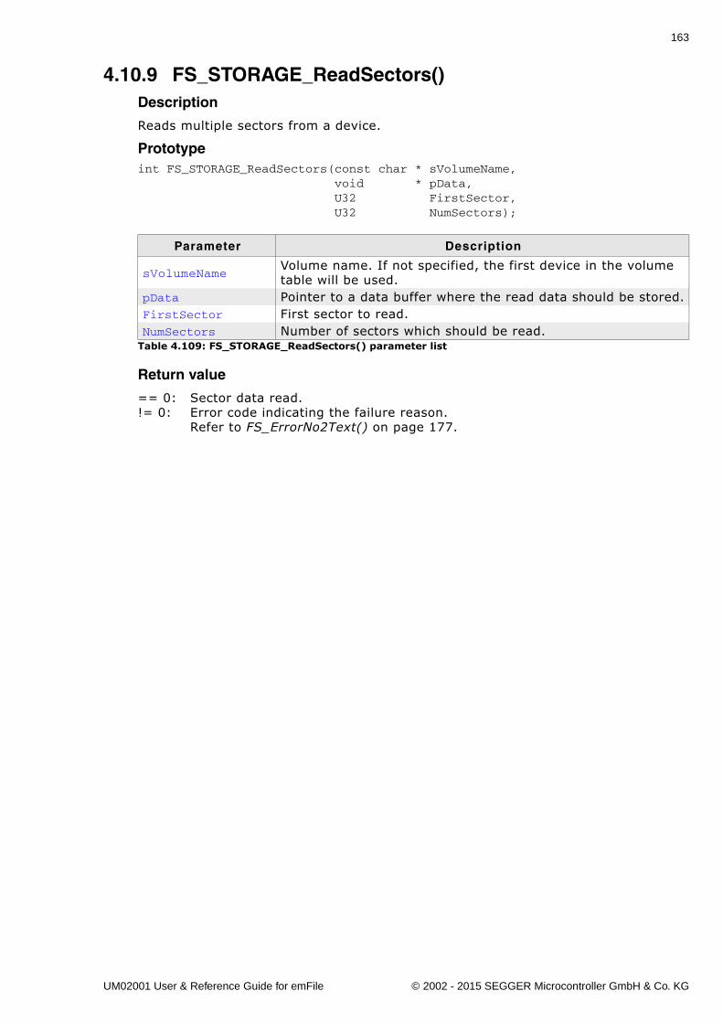
163
4.10.9 FS_STORAGE_ReadSectors()Description
Reads multiple sectors from a device.
Prototypeint FS_STORAGE_ReadSectors(const char * sVolumeName, void * pData, U32 FirstSector, U32 NumSectors);
Return value
== 0: Sector data read.!= 0: Error code indicating the failure reason.
Refer to FS_ErrorNo2Text() on page 177.
Parameter Description
sVolumeNameVolume name. If not specified, the first device in the volume table will be used.
pData Pointer to a data buffer where the read data should be stored.FirstSector First sector to read.NumSectors Number of sectors which should be read.
Table 4.109: FS_STORAGE_ReadSectors() parameter list
UM02001 User & Reference Guide for emFile © 2002 - 2015 SEGGER Microcontroller GmbH & Co. KG
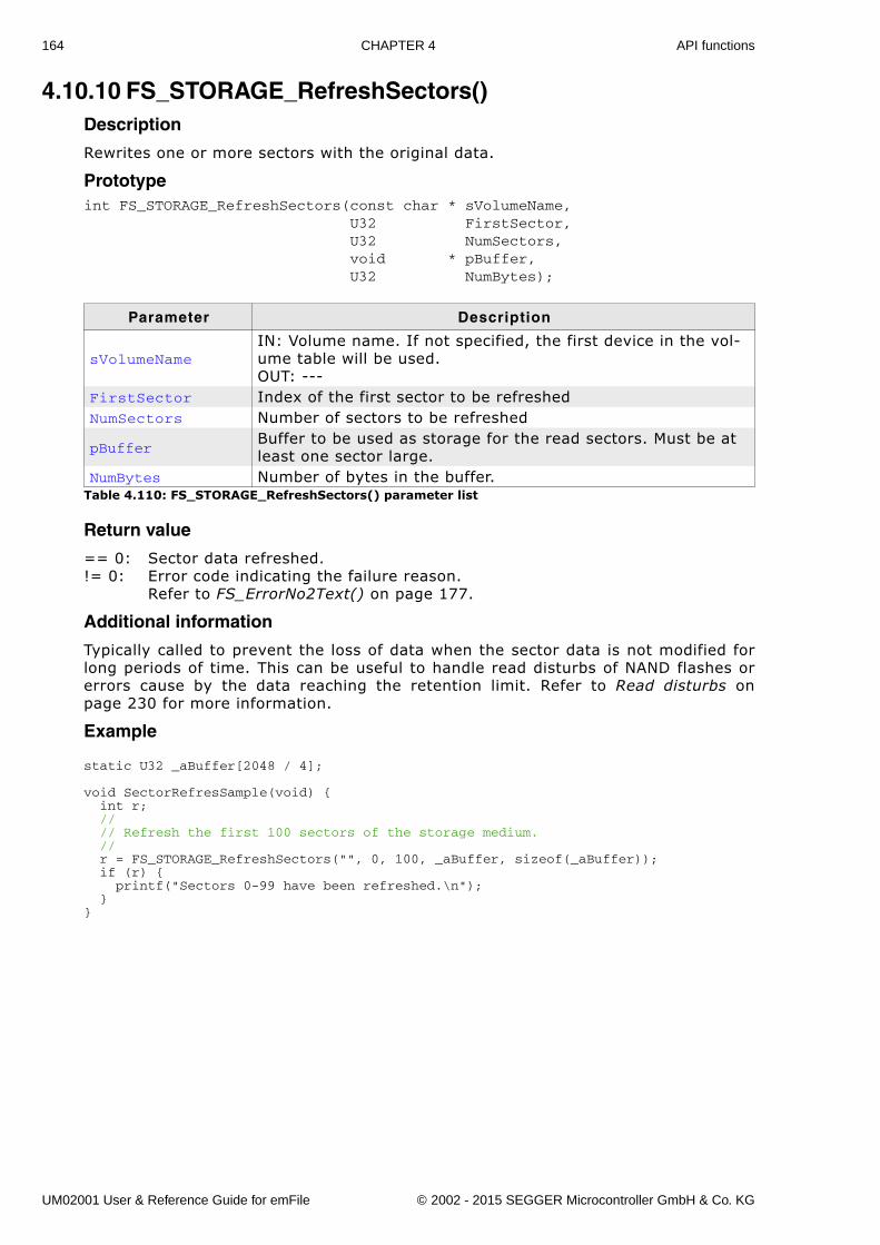
164 CHAPTER 4 API functions
4.10.10 FS_STORAGE_RefreshSectors()Description
Rewrites one or more sectors with the original data.
Prototypeint FS_STORAGE_RefreshSectors(const char * sVolumeName, U32 FirstSector, U32 NumSectors, void * pBuffer, U32 NumBytes);
Return value
== 0: Sector data refreshed.!= 0: Error code indicating the failure reason.
Refer to FS_ErrorNo2Text() on page 177.
Additional information
Typically called to prevent the loss of data when the sector data is not modified forlong periods of time. This can be useful to handle read disturbs of NAND flashes orerrors cause by the data reaching the retention limit. Refer to Read disturbs onpage 230 for more information.
Example
static U32 _aBuffer[2048 / 4];
void SectorRefresSample(void) { int r; // // Refresh the first 100 sectors of the storage medium. // r = FS_STORAGE_RefreshSectors("", 0, 100, _aBuffer, sizeof(_aBuffer)); if (r) { printf("Sectors 0-99 have been refreshed.\n"); }}
Parameter Description
sVolumeNameIN: Volume name. If not specified, the first device in the vol-ume table will be used.OUT: ---
FirstSector Index of the first sector to be refreshedNumSectors Number of sectors to be refreshed
pBufferBuffer to be used as storage for the read sectors. Must be at least one sector large.
NumBytes Number of bytes in the buffer.Table 4.110: FS_STORAGE_RefreshSectors() parameter list
UM02001 User & Reference Guide for emFile © 2002 - 2015 SEGGER Microcontroller GmbH & Co. KG
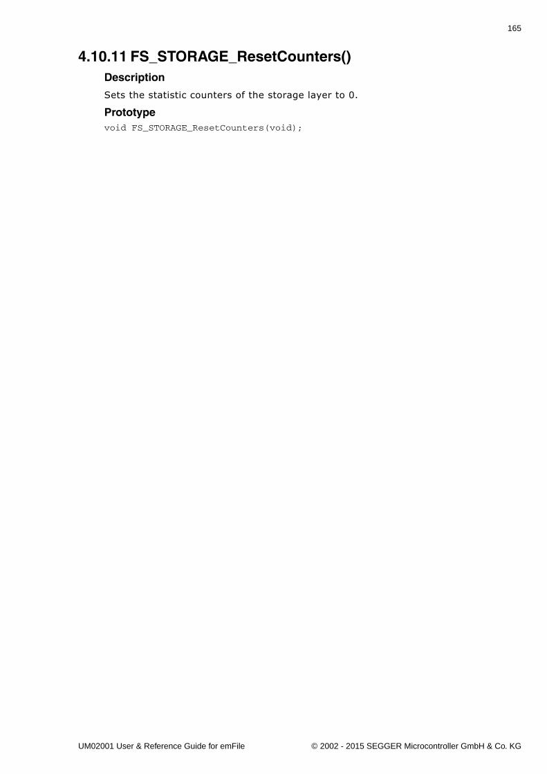
165
4.10.11 FS_STORAGE_ResetCounters()Description
Sets the statistic counters of the storage layer to 0.
Prototypevoid FS_STORAGE_ResetCounters(void);
UM02001 User & Reference Guide for emFile © 2002 - 2015 SEGGER Microcontroller GmbH & Co. KG
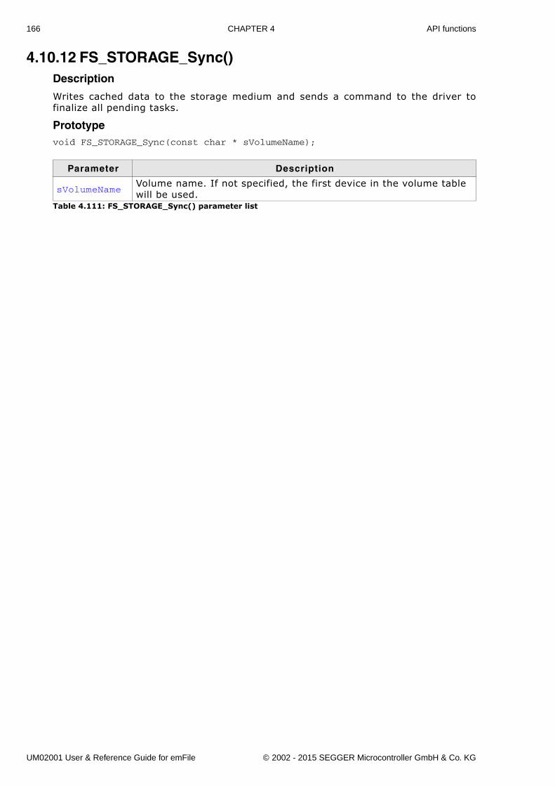
166 CHAPTER 4 API functions
4.10.12 FS_STORAGE_Sync()Description
Writes cached data to the storage medium and sends a command to the driver tofinalize all pending tasks.
Prototypevoid FS_STORAGE_Sync(const char * sVolumeName);
Parameter Description
sVolumeNameVolume name. If not specified, the first device in the volume table will be used.
Table 4.111: FS_STORAGE_Sync() parameter list
UM02001 User & Reference Guide for emFile © 2002 - 2015 SEGGER Microcontroller GmbH & Co. KG
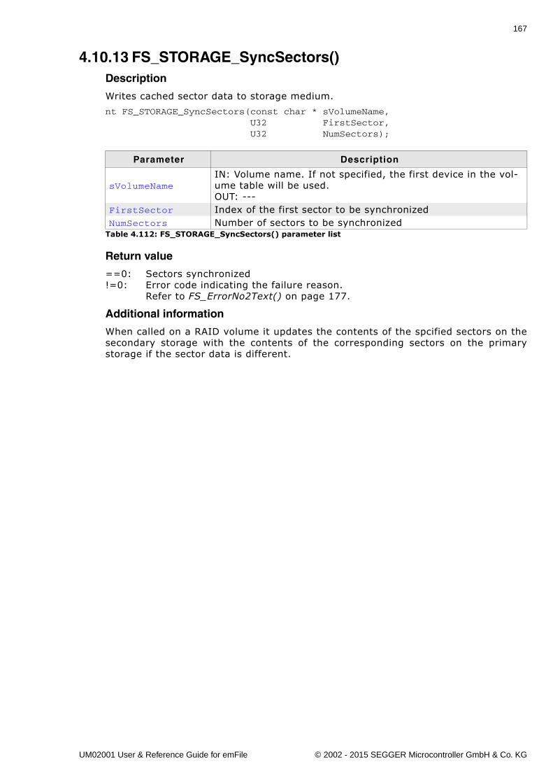
167
4.10.13 FS_STORAGE_SyncSectors()Description
Writes cached sector data to storage medium.
nt FS_STORAGE_SyncSectors(const char * sVolumeName, U32 FirstSector, U32 NumSectors);
Return value
==0: Sectors synchronized!=0: Error code indicating the failure reason.
Refer to FS_ErrorNo2Text() on page 177.
Additional information
When called on a RAID volume it updates the contents of the spcified sectors on thesecondary storage with the contents of the corresponding sectors on the primarystorage if the sector data is different.
Parameter Description
sVolumeNameIN: Volume name. If not specified, the first device in the vol-ume table will be used.OUT: ---
FirstSector Index of the first sector to be synchronizedNumSectors Number of sectors to be synchronized
Table 4.112: FS_STORAGE_SyncSectors() parameter list
UM02001 User & Reference Guide for emFile © 2002 - 2015 SEGGER Microcontroller GmbH & Co. KG
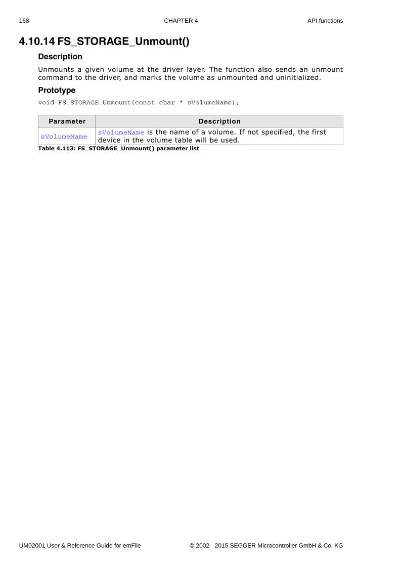
168 CHAPTER 4 API functions
4.10.14 FS_STORAGE_Unmount()Description
Unmounts a given volume at the driver layer. The function also sends an unmountcommand to the driver, and marks the volume as unmounted and uninitialized.
Prototypevoid FS_STORAGE_Unmount(const char * sVolumeName);
Parameter Description
sVolumeNamesVolumeName is the name of a volume. If not specified, the first device in the volume table will be used.
Table 4.113: FS_STORAGE_Unmount() parameter list
UM02001 User & Reference Guide for emFile © 2002 - 2015 SEGGER Microcontroller GmbH & Co. KG
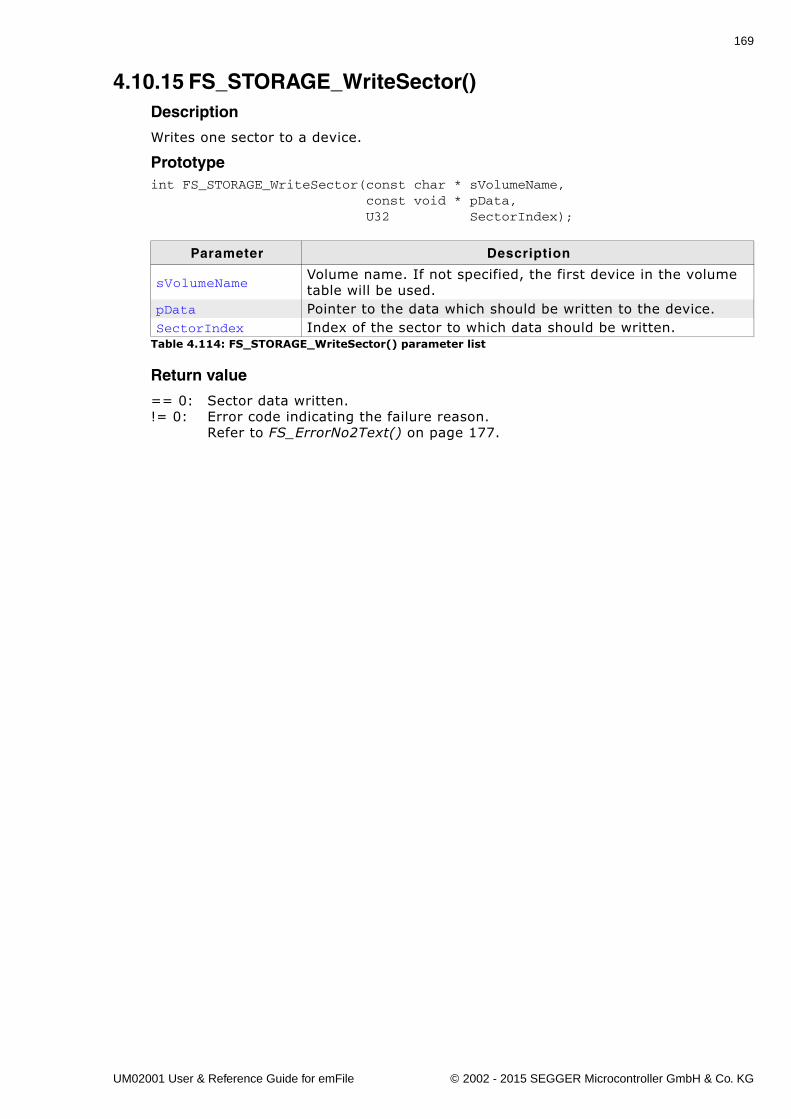
169
4.10.15 FS_STORAGE_WriteSector()Description
Writes one sector to a device.
Prototypeint FS_STORAGE_WriteSector(const char * sVolumeName, const void * pData, U32 SectorIndex);
Return value
== 0: Sector data written.!= 0: Error code indicating the failure reason.
Refer to FS_ErrorNo2Text() on page 177.
Parameter Description
sVolumeNameVolume name. If not specified, the first device in the volume table will be used.
pData Pointer to the data which should be written to the device.SectorIndex Index of the sector to which data should be written.
Table 4.114: FS_STORAGE_WriteSector() parameter list
UM02001 User & Reference Guide for emFile © 2002 - 2015 SEGGER Microcontroller GmbH & Co. KG
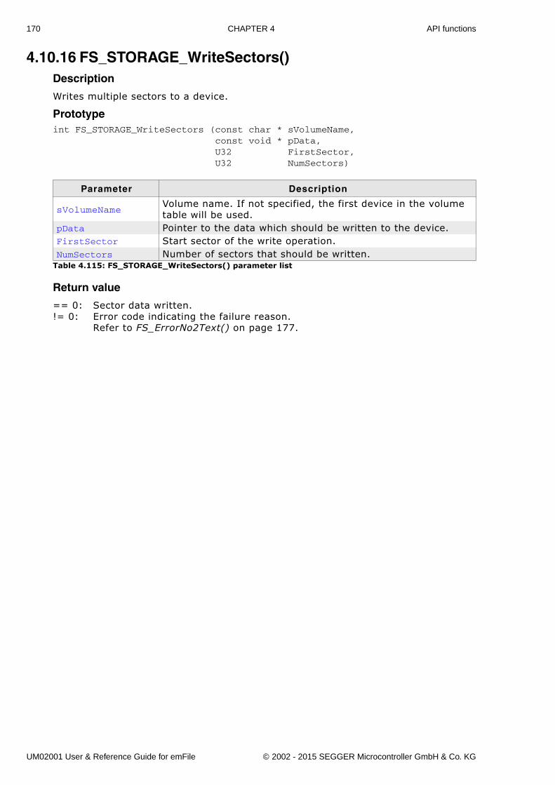
170 CHAPTER 4 API functions
4.10.16 FS_STORAGE_WriteSectors()Description
Writes multiple sectors to a device.
Prototypeint FS_STORAGE_WriteSectors (const char * sVolumeName, const void * pData, U32 FirstSector, U32 NumSectors)
Return value
== 0: Sector data written.!= 0: Error code indicating the failure reason.
Refer to FS_ErrorNo2Text() on page 177.
Parameter Description
sVolumeNameVolume name. If not specified, the first device in the volume table will be used.
pData Pointer to the data which should be written to the device.FirstSector Start sector of the write operation.NumSectors Number of sectors that should be written.
Table 4.115: FS_STORAGE_WriteSectors() parameter list
UM02001 User & Reference Guide for emFile © 2002 - 2015 SEGGER Microcontroller GmbH & Co. KG
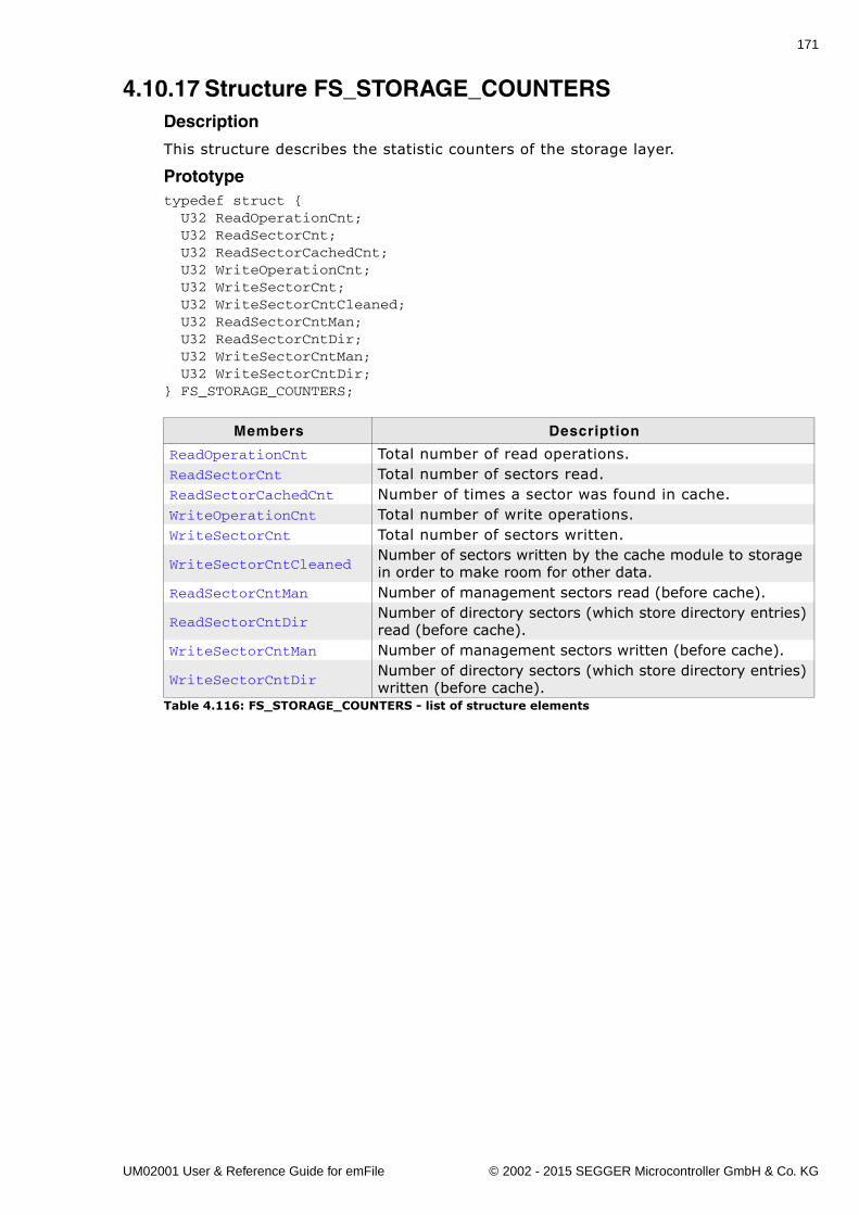
171
4.10.17 Structure FS_STORAGE_COUNTERSDescription
This structure describes the statistic counters of the storage layer.
Prototypetypedef struct { U32 ReadOperationCnt; U32 ReadSectorCnt; U32 ReadSectorCachedCnt; U32 WriteOperationCnt; U32 WriteSectorCnt; U32 WriteSectorCntCleaned; U32 ReadSectorCntMan; U32 ReadSectorCntDir; U32 WriteSectorCntMan; U32 WriteSectorCntDir;} FS_STORAGE_COUNTERS;
Members Description
ReadOperationCnt Total number of read operations.ReadSectorCnt Total number of sectors read.ReadSectorCachedCnt Number of times a sector was found in cache.WriteOperationCnt Total number of write operations.WriteSectorCnt Total number of sectors written.
WriteSectorCntCleanedNumber of sectors written by the cache module to storage in order to make room for other data.
ReadSectorCntMan Number of management sectors read (before cache).
ReadSectorCntDirNumber of directory sectors (which store directory entries) read (before cache).
WriteSectorCntMan Number of management sectors written (before cache).
WriteSectorCntDirNumber of directory sectors (which store directory entries) written (before cache).
Table 4.116: FS_STORAGE_COUNTERS - list of structure elements
UM02001 User & Reference Guide for emFile © 2002 - 2015 SEGGER Microcontroller GmbH & Co. KG
172 CHAPTER 4 API functions
4.11 FAT related functions
4.11.1 FS_FAT_GrowRootDir()Description
Enlarges the default size of the root directory of a FAT32 volume.
PrototypeU32 FS_FAT_GrowRootDir (const char * sVolumeName, U32 NumAddEntries);
Return value
>= 0: Number of entries added.== 0: Clusters after root directory are not free.== 0xFFFFFFFF: An error has occurred.
Additional Information
This function has to be called after formatting the volume. If the function is notcalled after format or called for a FAT12/16 volume the function will fail. In oppositeto FAT12 and FAT16 which have a fixed root directory size, the root directory of aFAT32 formatted device can be of variable size. By default, one cluster is reserved forthe root directory entries. Therefore, it can speed up performance to reserve addi-tional clusters for root directory entries after formatting the medium.
Parameter Description
pVolumeName Name of the device.NumAddEntries Numbers of directories entries to be added.
Table 4.117: FS_FAT_GrowRootDir() parameter list
UM02001 User & Reference Guide for emFile © 2002 - 2015 SEGGER Microcontroller GmbH & Co. KG
173
4.11.2 FS_FormatSD()Description
Performs a high-level format of a device according to the SD Specification - File sys-tem specification.
Prototypeint FS_FormatSD (const char * pVolumeName);
Return value
== 0: Format was successful.!= 0: Error code indicating the failure reason.
Refer to FS_ErrorNo2Text() on page 177.
Additional Information
For further information refer to SD Specification - Part 2 - File System Specification(May 9, 2006, www.sdcard.org).
Parameter Description
pVolumeName Name of the device to format.Table 4.118: FS_FormatSD() parameter list
UM02001 User & Reference Guide for emFile © 2002 - 2015 SEGGER Microcontroller GmbH & Co. KG
174 CHAPTER 4 API functions
4.11.3 FS_FAT_SupportLFN()Description
Adds long file name support to the file system.
Prototypevoid FS_FAT_SupportLFN(void);
Additional Information
The FAT file system was not designed for long file name (LFN) support, limitingnames to twelve characters (8.3). LFN support may be added to any of the FAT filesystems, but there are legal issues that must be settled with Microsoft before endapplications make use of this feature. Long file names are inherent to this proprietaryfile system relieving it of any legal issues.
Note: The LFN package is required to support long file names.
UM02001 User & Reference Guide for emFile © 2002 - 2015 SEGGER Microcontroller GmbH & Co. KG
175
4.11.4 FS_FAT_DisableLFN()Description
Disables the support for long file names for the FAT file system.
Prototypevoid FS_DisableLFN(void);
UM02001 User & Reference Guide for emFile © 2002 - 2015 SEGGER Microcontroller GmbH & Co. KG
176 CHAPTER 4 API functions
4.12 Error handling functions
4.12.1 FS_ClearErr()Description
Clears the error status of a file.
Prototypevoid FS_ClearErr(FS_FILE * pFile);
Additional Information
This routine should be called after you have detected an error so that you can checkfor success of the next file operations.
Example
void MainTask(void) { FS_FILE *pFile; int Err;
pFile = FS_FOpen("test.txt", "r"); if (pFile != 0) { Err = FS_FError(pFile); if (Err != FS_ERR_OK) { FS_ClearErr(pFile); } FS_FClose(pFile); }}
Parameter Description
pFile Pointer to a data structure of type FS_FILE.Table 4.119: FS_ClearErr() parameter list
UM02001 User & Reference Guide for emFile © 2002 - 2015 SEGGER Microcontroller GmbH & Co. KG
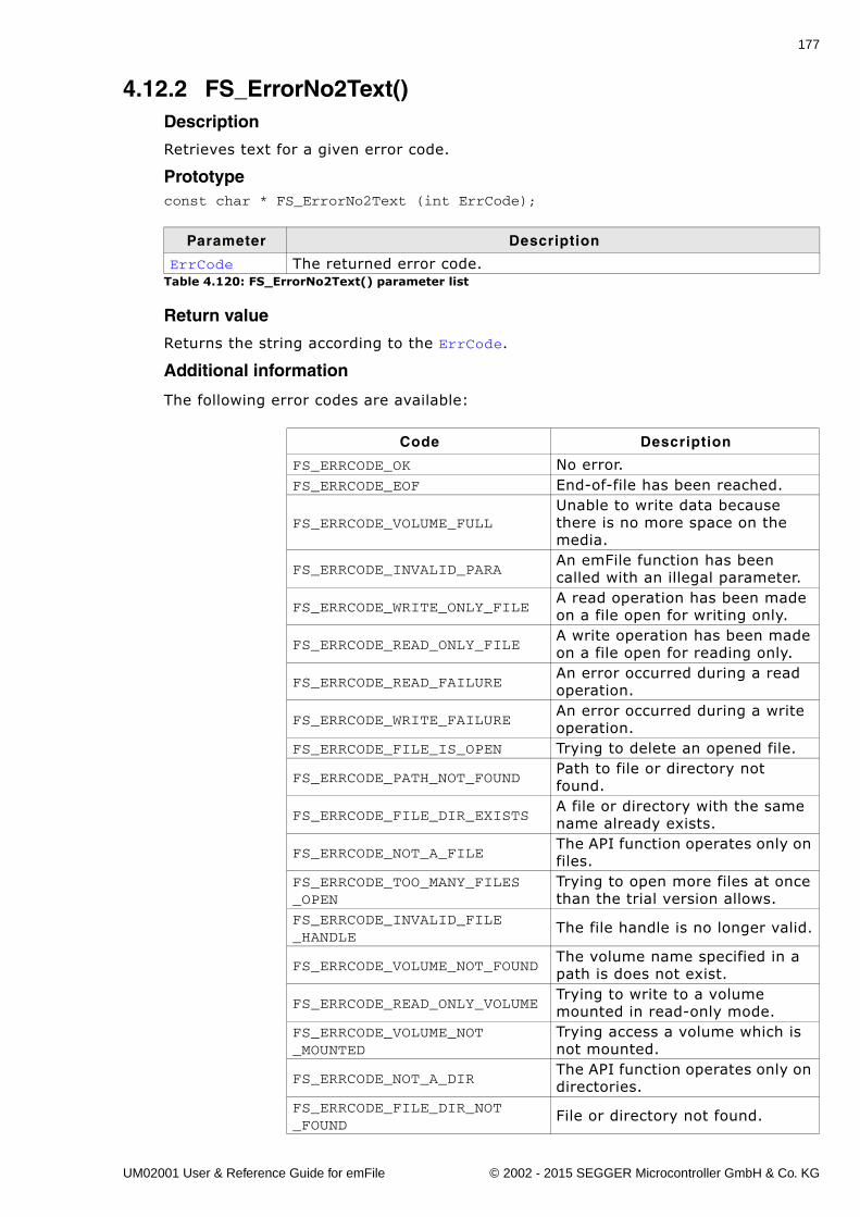
177
4.12.2 FS_ErrorNo2Text()Description
Retrieves text for a given error code.
Prototypeconst char * FS_ErrorNo2Text (int ErrCode);
Return value
Returns the string according to the ErrCode.
Additional information
The following error codes are available:
Parameter Description
ErrCode The returned error code.Table 4.120: FS_ErrorNo2Text() parameter list
Code Description
FS_ERRCODE_OK No error.FS_ERRCODE_EOF End-of-file has been reached.
FS_ERRCODE_VOLUME_FULLUnable to write data because there is no more space on the media.
FS_ERRCODE_INVALID_PARAAn emFile function has been called with an illegal parameter.
FS_ERRCODE_WRITE_ONLY_FILEA read operation has been made on a file open for writing only.
FS_ERRCODE_READ_ONLY_FILEA write operation has been made on a file open for reading only.
FS_ERRCODE_READ_FAILUREAn error occurred during a read operation.
FS_ERRCODE_WRITE_FAILUREAn error occurred during a write operation.
FS_ERRCODE_FILE_IS_OPEN Trying to delete an opened file.
FS_ERRCODE_PATH_NOT_FOUNDPath to file or directory not found.
FS_ERRCODE_FILE_DIR_EXISTSA file or directory with the same name already exists.
FS_ERRCODE_NOT_A_FILEThe API function operates only on files.
FS_ERRCODE_TOO_MANY_FILES_OPEN
Trying to open more files at once than the trial version allows.
FS_ERRCODE_INVALID_FILE_HANDLE
The file handle is no longer valid.
FS_ERRCODE_VOLUME_NOT_FOUNDThe volume name specified in a path is does not exist.
FS_ERRCODE_READ_ONLY_VOLUMETrying to write to a volume mounted in read-only mode.
FS_ERRCODE_VOLUME_NOT_MOUNTED
Trying access a volume which is not mounted.
FS_ERRCODE_NOT_A_DIRThe API function operates only on directories.
FS_ERRCODE_FILE_DIR_NOT_FOUND
File or directory not found.
UM02001 User & Reference Guide for emFile © 2002 - 2015 SEGGER Microcontroller GmbH & Co. KG
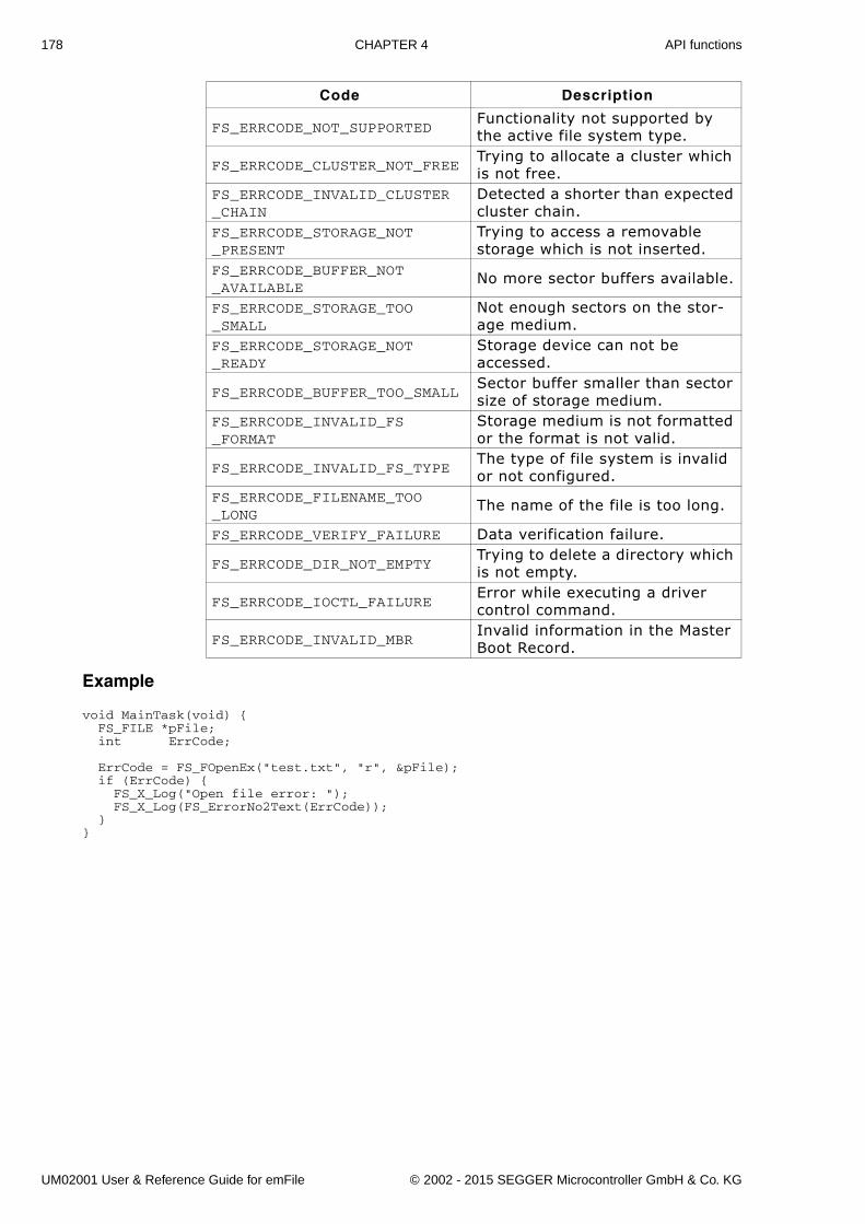
178 CHAPTER 4 API functions
Example
void MainTask(void) { FS_FILE *pFile; int ErrCode; ErrCode = FS_FOpenEx("test.txt", "r", &pFile); if (ErrCode) { FS_X_Log("Open file error: "); FS_X_Log(FS_ErrorNo2Text(ErrCode)); }}
FS_ERRCODE_NOT_SUPPORTEDFunctionality not supported by the active file system type.
FS_ERRCODE_CLUSTER_NOT_FREETrying to allocate a cluster which is not free.
FS_ERRCODE_INVALID_CLUSTER_CHAIN
Detected a shorter than expected cluster chain.
FS_ERRCODE_STORAGE_NOT_PRESENT
Trying to access a removable storage which is not inserted.
FS_ERRCODE_BUFFER_NOT_AVAILABLE
No more sector buffers available.
FS_ERRCODE_STORAGE_TOO_SMALL
Not enough sectors on the stor-age medium.
FS_ERRCODE_STORAGE_NOT_READY
Storage device can not be accessed.
FS_ERRCODE_BUFFER_TOO_SMALLSector buffer smaller than sector size of storage medium.
FS_ERRCODE_INVALID_FS_FORMAT
Storage medium is not formatted or the format is not valid.
FS_ERRCODE_INVALID_FS_TYPEThe type of file system is invalid or not configured.
FS_ERRCODE_FILENAME_TOO_LONG
The name of the file is too long.
FS_ERRCODE_VERIFY_FAILURE Data verification failure.
FS_ERRCODE_DIR_NOT_EMPTYTrying to delete a directory which is not empty.
FS_ERRCODE_IOCTL_FAILUREError while executing a driver control command.
FS_ERRCODE_INVALID_MBRInvalid information in the Master Boot Record.
Code Description
UM02001 User & Reference Guide for emFile © 2002 - 2015 SEGGER Microcontroller GmbH & Co. KG
179
4.12.3 FS_FEof()Description
Tests for end-of-file on a given file pointer.
Prototypeint FS_FEof (FS_FILE * pFile);
Return value
== 0: If the end of file has not been reached.== 1: If the end of file has been reached.
Additional Information
The FS_FEof function determines whether the end of a given file pointer has beenreached. When end of file is reached, read operations return an end-of-file indicatoruntil the file pointer is closed or until FS_FSeek, or FS_ClearErr is called against it.
Example
int ReadFile(FS_File * pFile, char * pBuffer, int NumBytes) { FS_FILE * pFile; char acBuffer[100]; char acLog[100]; int Count; int Total; I16 Error;
Total = 0; pFile = FS_FOpen("default.txt", "r"); if (pFile == NULL) { FS_X_ErrorOut("Could not open file.");’ } /* Cycle until end of file reached: */ while (!FS_FEof(pFile)) { Count = FS_Read(pFile, &acBuffer[0], sizeof(acBuffer)); Error = FS_FError(pFile); if (Error) { sprintf(acLog, "Could not read from file:\nReason = %s", FS_ErrorNo2Text(Error)); FS_X_ErrorOut(acLog); break; } /* Total up actual bytes read */ Total += Count; } sprintf(acLog, "Number of read bytes = %d\n", Total); FS_X_Log(acLog); FS_FClose(pFile);}
Parameter Description
pFile Pointer to a data structure of type FS_FILE.Table 4.121: FS_FEof() parameter list
UM02001 User & Reference Guide for emFile © 2002 - 2015 SEGGER Microcontroller GmbH & Co. KG
180 CHAPTER 4 API functions
4.12.4 FS_FError()Description
Returns the current error status of a file.
PrototypeI16 FS_FError (FS_FILE * pFile);
Return value
FS_ERR_OK if no errors.A value not equal to FS_ERR_OK if a file operation caused an error.
Additional Information
The return value is not FS_ERR_OK only when a file operation caused an error and theerror was not cleared by calling FS_ClearErr() or any other operation that clears theprevious error status.
Example
void MainTask(void) { FS_FILE *pFile;
pFile = FS_FOpen("test.txt", "r"); if (pFile != 0) { I16 Err; Err = FS_FError(pFile); FS_FClose(pFile); }}
Parameter Description
pFile Pointer to a data structure of type FS_FILE.Table 4.122: FS_FError() parameter list
UM02001 User & Reference Guide for emFile © 2002 - 2015 SEGGER Microcontroller GmbH & Co. KG
181
4.13 Obsolete functionsThis section contains reference information for obsolete functions.
4.13.1 FS_CloseDir()Description
Closes a directory referred to by the parameter pDir.
Prototypeint FS_CloseDir (FS_DIR * pDir);
Return Value
== 0: If the directory was successfully closed.== -1: In case of any error.
Example
void MainTask(void) { FS_DIR *pDir; FS_DIRENT *pDirEnt;
pDir = FS_OpenDir(""); /* Open the root directory of default device */ if (pDir) { do { char acDirName[20]; pDirEnt = FS_ReadDir(pDir); FS_DirEnt2Name(pDirEnt, acDirName); /* Get name of the current DirEntry */ if ((void*)pDirEnt == NULL) { break; /* No more files or directories */ } sprintf(_acBuffer," %s\n", acName); FS_X_Log(_acBuffer); } while (1); FS_CloseDir(pDir); } else { FS_X_ErrorOut("Unable to open directory\n");}
Parameter Description
pDir Pointer to a data structure of type FS_DIR.Table 4.123: FS_CloseDir() parameter list
UM02001 User & Reference Guide for emFile © 2002 - 2015 SEGGER Microcontroller GmbH & Co. KG
182 CHAPTER 4 API functions
4.13.2 FS_ConfigUpdateDirOnWrite()Description
Configures if the file system should update the directory entry on date write.
Prototypevoid FS_ConfigUpdateDirOnWrite(char OnOff);
Additional Information
Use the FS_SetFileWriteMode() function instead.
Parameter Description
OnOff==1 means enable update directory after write (Default).==0 means do not update directory.
Table 4.124: FS_ConfigUpdateDirOnWrite() parameter list
UM02001 User & Reference Guide for emFile © 2002 - 2015 SEGGER Microcontroller GmbH & Co. KG
183
4.13.3 FS_DirEnt2Attr()Description
Retrieves the attributes of the directory entry referred to by pDirEnt.
Prototypevoid FS_DirEnt2Attr (FS_DIRENT * pDirEnt, U8 * pAttr);
Additional Information
These attributes are available:
pDirEnt should point to a valid FS_DIRENT structure. FS_DirEnt2Attr() checks ifthe pointer is valid. To get a valid pointer, FS_ReadDir() should be called beforeusing FS_DirEnt2Attr(). Refer to FS_ReadDir() on page 191 for more information.
Example
void MainTask(void) { FS_DIR *pDir; FS_DIRENT *pDirEnt; char acBuffer[200]; pDir = FS_OpenDir(""); /* Open root directory of default device */ if (pDir) { do { char acName[20]; U8 Attr; pDirEnt = FS_ReadDir(pDir); FS_DirEnt2Name(pDirEnt, acName); FS_DirEnt2Attr(pDirEnt, &Attr); if ((void*)pDirEnt == NULL) { break; /* No more files */ } sprintf(_acBuffer," %s %s Attributes: %s%s%s%s\n", acName, (Attr & FS_ATTR_DIRECTORY) ? "(Dir)" : " ", (Attr & FS_ATTR_ARCHIVE) ? "A" : "-", (Attr & FS_ATTR_READ_ONLY) ? "R" : "-", (Attr & FS_ATTR_HIDDEN) ? "H" : "-", (Attr & FS_ATTR_SYSTEM) ? "S" : "-"); FS_X_Log(acBuffer); } while (1); FS_CloseDir(pDir); } else { FS_X_ErrorOut("Unable to open directory\n"); }}
Parameter Description
pDirEnt Pointer to a directory entry, read by FS_ReadDir().pAttr Pointer to U8 variable in which the attributes should be stored.
Table 4.125: FS_DirEnt2Attr() parameter list
Parameter Description
FS_ATTR_DIRECTORY pDirEnt is a directory.FS_ATTR_ARCHIVE pDirEnt has the ARCHIVE attribute set.FS_ATTR_READ_ONLY pDirEnt has the READ ONLY attribute set.FS_ATTR_HIDDEN pDirEnt has the HIDDEN attribute set.SYSTEM pDirEnt has the SYSTEM attribute set.
Table 4.126: FS_DirEnt2Attr() - list of possible attributes
UM02001 User & Reference Guide for emFile © 2002 - 2015 SEGGER Microcontroller GmbH & Co. KG
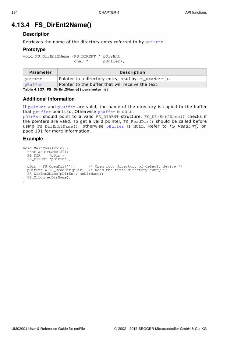
184 CHAPTER 4 API functions
4.13.4 FS_DirEnt2Name()Description
Retrieves the name of the directory entry referred to by pDirEnt.
Prototypevoid FS_DirEnt2Name (FS_DIRENT * pDirEnt, char * pBuffer);
Additional Information
If pDirEnt and pBuffer are valid, the name of the directory is copied to the bufferthat pBuffer points to. Otherwise pBuffer is NULL.pDirEnt should point to a valid FS_DIRENT structure. FS_DirEnt2Name() checks ifthe pointers are valid. To get a valid pointer, FS_ReadDir() should be called beforeusing FS_DirEnt2Name(), otherwise pBuffer is NULL. Refer to FS_ReadDir() onpage 191 for more information.
Example
void MainTask(void) { char acDirName[20]; FS_DIR *pDir ; FS_DIRENT *pDirEnt ;
pDir = FS_OpenDir(""); /* Open root directory of default device */ pDirEnt = FS_ReadDir(pDir); /* Read the first directory entry */ FS_DirEnt2Name(pDirEnt, acDirName); FS_X_Log(acDirName);}
Parameter Description
pDirEnt Pointer to a directory entry, read by FS_ReadDir().pBuffer Pointer to the buffer that will receive the text.
Table 4.127: FS_DirEnt2Name() parameter list
UM02001 User & Reference Guide for emFile © 2002 - 2015 SEGGER Microcontroller GmbH & Co. KG
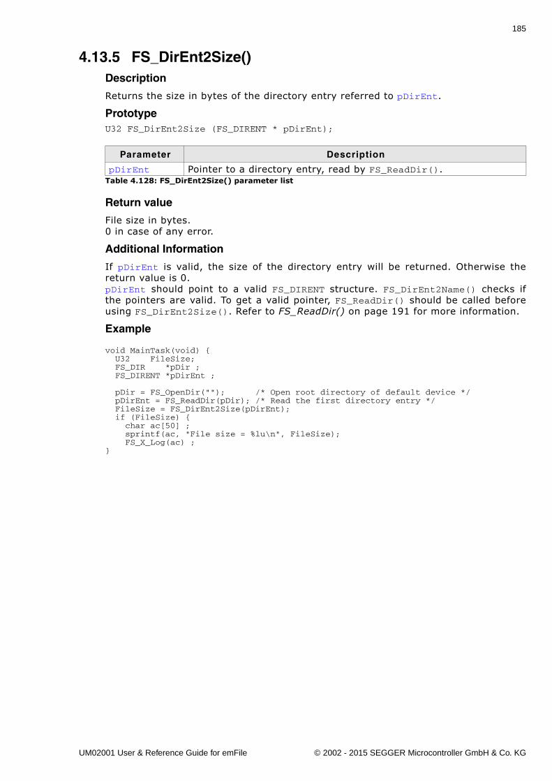
185
4.13.5 FS_DirEnt2Size()Description
Returns the size in bytes of the directory entry referred to pDirEnt.
PrototypeU32 FS_DirEnt2Size (FS_DIRENT * pDirEnt);
Return value
File size in bytes.0 in case of any error.
Additional Information
If pDirEnt is valid, the size of the directory entry will be returned. Otherwise thereturn value is 0.pDirEnt should point to a valid FS_DIRENT structure. FS_DirEnt2Name() checks ifthe pointers are valid. To get a valid pointer, FS_ReadDir() should be called beforeusing FS_DirEnt2Size(). Refer to FS_ReadDir() on page 191 for more information.
Example
void MainTask(void) { U32 FileSize; FS_DIR *pDir ; FS_DIRENT *pDirEnt ;
pDir = FS_OpenDir(""); /* Open root directory of default device */ pDirEnt = FS_ReadDir(pDir); /* Read the first directory entry */ FileSize = FS_DirEnt2Size(pDirEnt); if (FileSize) { char ac[50] ; sprintf(ac, "File size = %lu\n", FileSize); FS_X_Log(ac) ;}
Parameter Description
pDirEnt Pointer to a directory entry, read by FS_ReadDir().Table 4.128: FS_DirEnt2Size() parameter list
UM02001 User & Reference Guide for emFile © 2002 - 2015 SEGGER Microcontroller GmbH & Co. KG
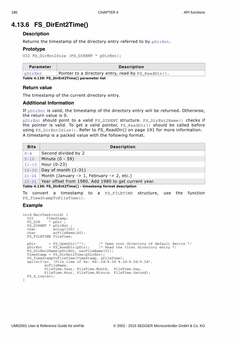
186 CHAPTER 4 API functions
4.13.6 FS_DirEnt2Time()Description
Returns the timestamp of the directory entry referred to by pDirEnt.
PrototypeU32 FS_DirEnt2Size (FS_DIRENT * pDirEnt);
Return value
The timestamp of the current directory entry.
Additional Information
If pDirEnt is valid, the timestamp of the directory entry will be returned. Otherwise,the return value is 0.pDirEnt should point to a valid FS_DIRENT structure. FS_DirEnt2Name() checks ifthe pointer is valid. To get a valid pointer, FS_ReadDir() should be called beforeusing FS_DirEnt2Size(). Refer to FS_ReadDir() on page 191 for more information.A timestamp is a packed value with the following format.
To convert a timestamp to a FS_FILETIME structure, use the functionFS_TimeStampToFileTime().
Example
void MainTask(void) { U32 TimeStamp; FS_DIR * pDir ; FS_DIRENT * pDirEnt ; char acLog[100] ; char acFileName[40]; FS_FILETIME FileTime;
pDir = FS_OpenDir(""); /* Open root directory of default device */ pDirEnt = FS_ReadDir(pDir); /* Read the first directory entry */ FS_DirEnt2Name(pDirEnt, &acFileName[0]); TimeStamp = FS_DirEnt2Time(pDirEnt); FS_TimeStampToFileTime(TimeStamp, &FileTime); sprintf(ac, "File time of %s: %d-.2d-%.2d %.2d:%.2d:%.2d", acFileName, FileTime.Year, FileTime.Month, FileTime.Day, FileTime.Hour, FileTime.Minute, FileTime.Second); FS_X_Log(ac);}
Parameter Description
pDirEnt Pointer to a directory entry, read by FS_ReadDir().Table 4.129: FS_DirEnt2Time() parameter list
Bits Description
0-4 Second divided by 25-10 Minute (0 - 59)11-15 Hour (0-23)16-20 Day of month (1-31)21-24 Month (January -> 1, February -> 2, etc.)25-31 Year offset from 1980. Add 1980 to get current year.
Table 4.130: FS_DirEnt2Time() - timestamp format description
UM02001 User & Reference Guide for emFile © 2002 - 2015 SEGGER Microcontroller GmbH & Co. KG
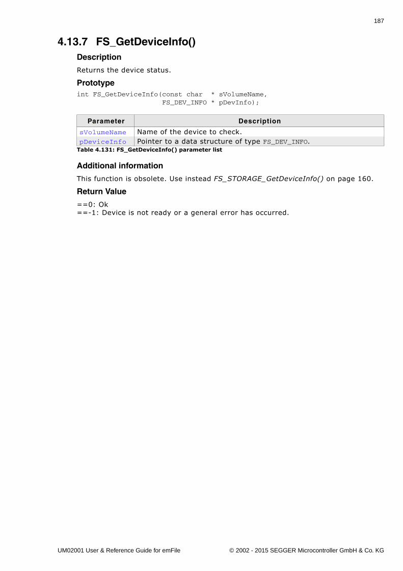
187
4.13.7 FS_GetDeviceInfo()Description
Returns the device status.
Prototypeint FS_GetDeviceInfo(const char * sVolumeName, FS_DEV_INFO * pDevInfo);
Additional information
This function is obsolete. Use instead FS_STORAGE_GetDeviceInfo() on page 160.
Return Value
==0: Ok==-1: Device is not ready or a general error has occurred.
Parameter Description
sVolumeName Name of the device to check.pDeviceInfo Pointer to a data structure of type FS_DEV_INFO.
Table 4.131: FS_GetDeviceInfo() parameter list
UM02001 User & Reference Guide for emFile © 2002 - 2015 SEGGER Microcontroller GmbH & Co. KG
188 CHAPTER 4 API functions
4.13.8 FS_GetNumFiles()Description
Returns the number of files in a directory opened by FS_OpenDir().
PrototypeU32 FS_GetNumFiles (FS_DIR * pDir);
Return value
Number of files in a directory. 0xFFFFFFFF as return value indicates an error.
Additional Information
If pDir is valid, the number of files in the directory will be returned. To get a validpointer, FS_OpenDir() should be called before using FS_GetNumFiles(). Refer toFS_OpenDir() on page 190 for more information.
Example
void NumFilesInDirectory(void) { U32 NumFilesInDir; FS_DIR *pDir ;
pDir = FS_OpenDir(""); /* Open root directory of default device */ NumFilesInDir = FS_GetNumFiles(pDir); if (NumFilesInDir) { char ac[50] ; sprintf(ac, "NumFilesInDir = %lu\n", NumFilesInDir); FS_X_Log(ac) ; }}
Parameter Description
pDir Pointer to a FS_FILE data structure.Table 4.132: FS_GetNumFiles() parameter list
UM02001 User & Reference Guide for emFile © 2002 - 2015 SEGGER Microcontroller GmbH & Co. KG
189
4.13.9 FS_InitStorage()Description
This function only initializes the driver and OS if necessary.
Prototypevoid FS_InitStorage (void);
Return value
The return value indicates the caller how many drivers can be used at the same time.The function will accordingly allocate the sector buffers that are necessary for a filesystem operation.
Additional information
If FS_InitStorage() is used to initialize a driver only the hardware layer functionsFS_ReadSector(), FS_WriteSector(), and FS_GetDeviceInfo() are available.
This function is obsolete. Use instead FS_STORAGE_Init() on page 161.
UM02001 User & Reference Guide for emFile © 2002 - 2015 SEGGER Microcontroller GmbH & Co. KG
190 CHAPTER 4 API functions
4.13.10 FS_OpenDir()Description
Opens an existing directory for reading.
PrototypeFS_DIR *FS_OpenDir (const char * pDirname);
Return value
Returns the address of an FS_DIR data structure if the directory was opened.In case of any error the return value is 0.
Additional Information
A fully qualified directory name looks like:
[DevName:[UnitNum:]][DirPathList]DirectoryName
where:
� DevName is the name of a device, for example �ram� or �mmc�. If not specified, thefirst device in the device table will be used.UnitNum is the number for the unit of the device. If not specified, unit 0 will beused. Note that it is not allowed to specify UnitNum if DevName has not been spec-ified.
� DirPathList is a complete path to an existing subdirectory. The path must startand end with a '\' character. Directory names in the path are separated by '\'. IfDirPathList is not specified, the root directory on the device will be used.
� DirectoryName and all other directory names have to follow the standard FATnaming conventions (for example 8.3 notation), if support for long file names isnot enabled.
To open the root directory, simply use an empty string for pDirName.
Example
FS_DIR *pDir;
void FSTask1(void) { /* Open directory test - default driver on default device */ pDir = FS_OpenDir("test");}
void FSTask2(void) { /* Open root directory - RAM device driver on default device */ pDir = FS_OpenDir("ram:");}
Parameter Description
pDirName Fully qualified directory name.Table 4.133: FS_OpenDir() parameter list
UM02001 User & Reference Guide for emFile © 2002 - 2015 SEGGER Microcontroller GmbH & Co. KG
191
4.13.11 FS_ReadDir()Description
Reads next directory entry in directory specified by pDir.
PrototypeFS_DIRENT *FS_ReadDir (FS_DIR * pDir);
Return value
Returns a pointer to a directory entry.If there are no more entries in the directory or in case of any error, 0 is returned.
Example
Refer to FS_CloseDir() on page 181.
Parameter Description
pDir Pointer to an opened directory.Table 4.134: FS_ReadDir() parameter list
UM02001 User & Reference Guide for emFile © 2002 - 2015 SEGGER Microcontroller GmbH & Co. KG
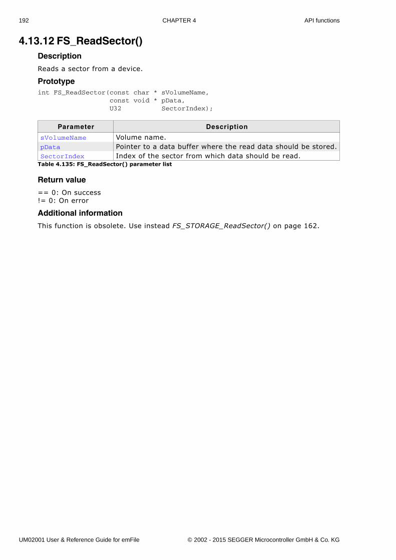
192 CHAPTER 4 API functions
4.13.12 FS_ReadSector()Description
Reads a sector from a device.
Prototypeint FS_ReadSector(const char * sVolumeName, const void * pData, U32 SectorIndex);
Return value
== 0: On success!= 0: On error
Additional information
This function is obsolete. Use instead FS_STORAGE_ReadSector() on page 162.
Parameter Description
sVolumeName Volume name.pData Pointer to a data buffer where the read data should be stored.SectorIndex Index of the sector from which data should be read.
Table 4.135: FS_ReadSector() parameter list
UM02001 User & Reference Guide for emFile © 2002 - 2015 SEGGER Microcontroller GmbH & Co. KG
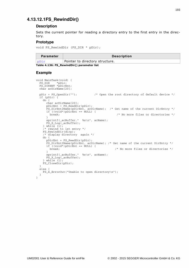
193
4.13.12.1FS_RewindDir()Description
Sets the current pointer for reading a directory entry to the first entry in the direc-tory.
Prototypevoid FS_RewindDir (FS_DIR * pDir);
Example
void MainTask(void) { FS_DIR *pDir; FS_DIRENT *pDirEnt; char acDirName[20];
pDir = FS_OpenDir(""); /* Open the root directory of default device */ if (pDir) { do { char acDirName[20]; pDirEnt = FS_ReadDir(pDir); FS_DirEnt2Name(pDirEnt, acDirName); /* Get name of the current DirEntry */ if ((void*)pDirEnt == NULL) { break; /* No more files or directories */ } sprintf(_acBuffer," %s\n", acName); FS_X_Log(_acBuffer); } while (1); /* rewind to 1st entry */ FS_RewindDir(dirp); /* display directory again */ do { pDirEnt = FS_ReadDir(pDir); FS_DirEnt2Name(pDirEnt, acDirName); /* Get name of the current DirEntry */ if ((void*)pDirEnt == NULL) { break; /* No more files or directories */ } sprintf(_acBuffer," %s\n", acName); FS_X_Log(_acBuffer); } while (1); FS_CloseDir(pDir); } else { FS_X_ErrorOut("Unable to open directory\n"); }}
Parameter Description
pDir Pointer to directory structure.Table 4.136: FS_RewindDir() parameter list
UM02001 User & Reference Guide for emFile © 2002 - 2015 SEGGER Microcontroller GmbH & Co. KG
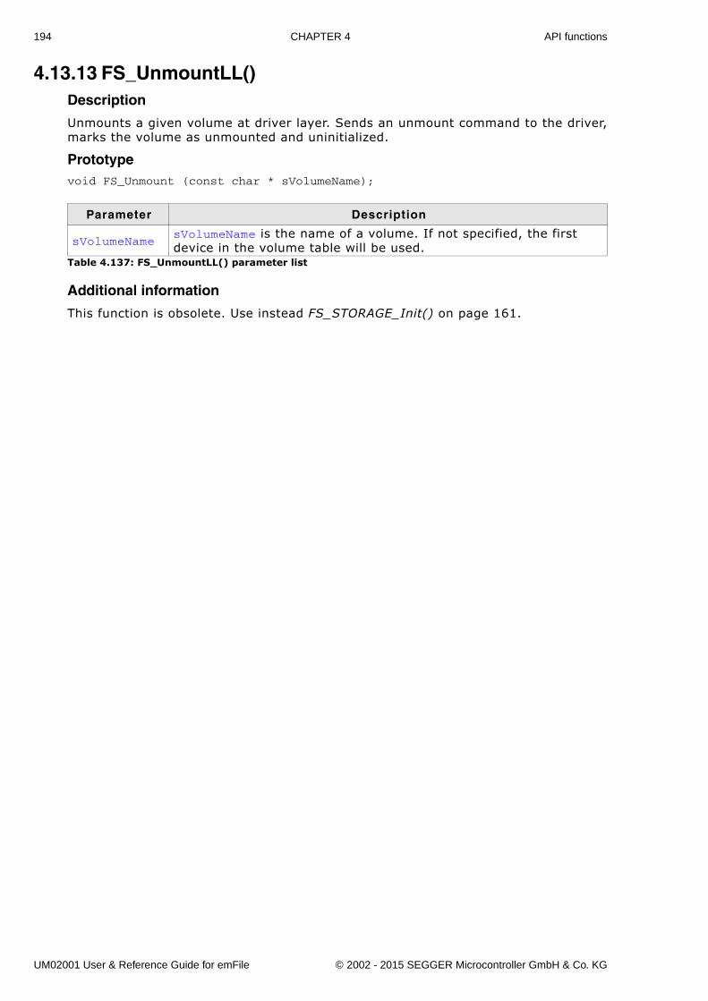
194 CHAPTER 4 API functions
4.13.13 FS_UnmountLL()Description
Unmounts a given volume at driver layer. Sends an unmount command to the driver,marks the volume as unmounted and uninitialized.
Prototypevoid FS_Unmount (const char * sVolumeName);
Additional information
This function is obsolete. Use instead FS_STORAGE_Init() on page 161.
Parameter Description
sVolumeNamesVolumeName is the name of a volume. If not specified, the first device in the volume table will be used.
Table 4.137: FS_UnmountLL() parameter list
UM02001 User & Reference Guide for emFile © 2002 - 2015 SEGGER Microcontroller GmbH & Co. KG
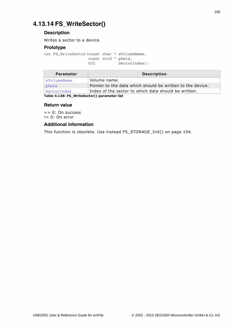
195
4.13.14 FS_WriteSector()Description
Writes a sector to a device.
Prototypeint FS_WriteSector(const char * sVolumeName, const void * pData, U32 SectorIndex);
Return value
== 0: On success!= 0: On error
Additional information
This function is obsolete. Use instead FS_STORAGE_Init() on page 104.
Parameter Description
sVolumeName Volume name.pData Pointer to the data which should be written to the device.SectorIndex Index of the sector to which data should be written.
Table 4.138: FS_WriteSector() parameter list
UM02001 User & Reference Guide for emFile © 2002 - 2015 SEGGER Microcontroller GmbH & Co. KG

196 CHAPTER 4 API functions
UM02001 User & Reference Guide for emFile © 2002 - 2015 SEGGER Microcontroller GmbH & Co. KG
197
Chapter 5
Optimizing performance - Caching and buffering
This chapter gives an introduction into emFile�s cache handling. Furthermore, it con-tains the function description and an example.
UM02001 User & Reference Guide for emFile © 2002 - 2015 SEGGER Microcontroller GmbH & Co. KG
198 CHAPTER 5 Optimizing performance - Caching and buffering
5.1 IntroductionA cache is a storage area where frequently used data can be stored for fast access.In many cases, this can enhance the average execution time. Applications which donot use a cache data will always be read from the storage medium even if it has beenused before. A cache stores accessed and processed data. If the data should be pro-cessed again, it will be copied out of the cache instead of refetching it from the stor-age medium. This is called a �hit�. When the data is not present in the cache andmust be read from the storage it is called a �miss�.
Write cache and journaling
Do not use a write cache when the journaling is enabled. The journaling will not workproperly if any form of write cache is configured. More detailed information can befound in the section Journaling and write caching on page 512.
UM02001 User & Reference Guide for emFile © 2002 - 2015 SEGGER Microcontroller GmbH & Co. KG
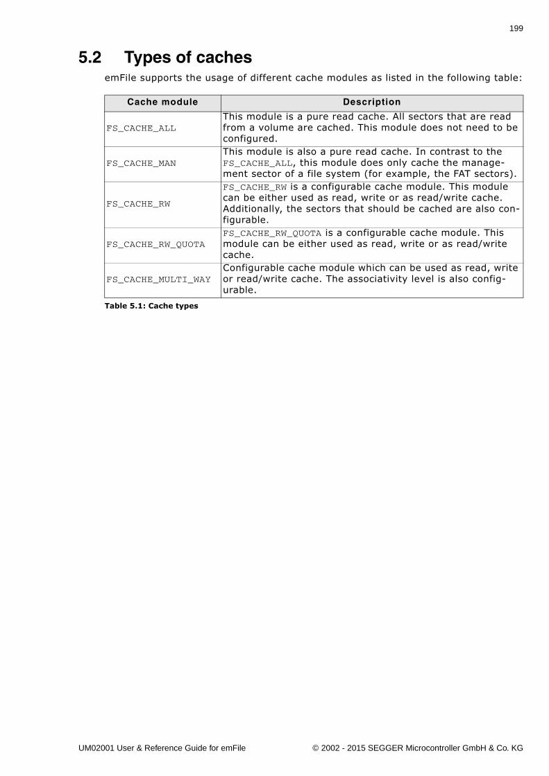
199
5.2 Types of cachesemFile supports the usage of different cache modules as listed in the following table:
Cache module Description
FS_CACHE_ALLThis module is a pure read cache. All sectors that are read from a volume are cached. This module does not need to be configured.
FS_CACHE_MANThis module is also a pure read cache. In contrast to the FS_CACHE_ALL, this module does only cache the manage-ment sector of a file system (for example, the FAT sectors).
FS_CACHE_RW
FS_CACHE_RW is a configurable cache module. This module can be either used as read, write or as read/write cache. Additionally, the sectors that should be cached are also con-figurable.
FS_CACHE_RW_QUOTAFS_CACHE_RW_QUOTA is a configurable cache module. This module can be either used as read, write or as read/write cache.
FS_CACHE_MULTI_WAYConfigurable cache module which can be used as read, write or read/write cache. The associativity level is also config-urable.
Table 5.1: Cache types
UM02001 User & Reference Guide for emFile © 2002 - 2015 SEGGER Microcontroller GmbH & Co. KG
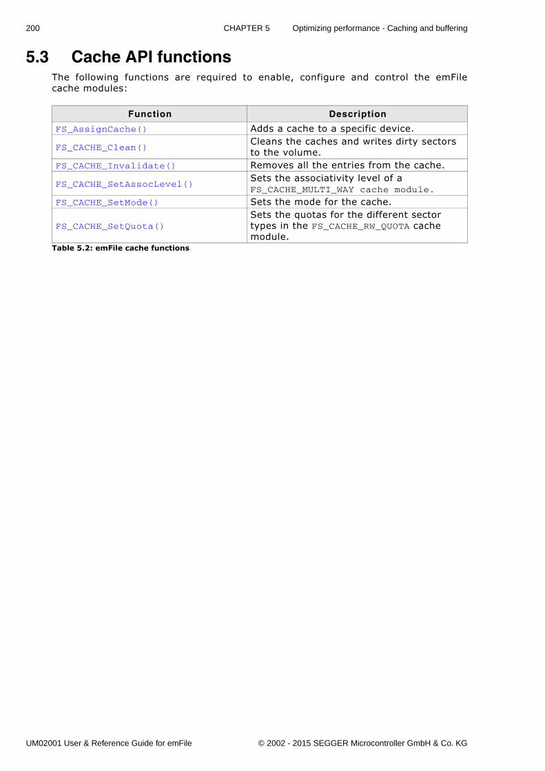
200 CHAPTER 5 Optimizing performance - Caching and buffering
5.3 Cache API functionsThe following functions are required to enable, configure and control the emFilecache modules:
Function Description
FS_AssignCache() Adds a cache to a specific device.
FS_CACHE_Clean()Cleans the caches and writes dirty sectors to the volume.
FS_CACHE_Invalidate() Removes all the entries from the cache.
FS_CACHE_SetAssocLevel()Sets the associativity level of a FS_CACHE_MULTI_WAY cache module.
FS_CACHE_SetMode() Sets the mode for the cache.
FS_CACHE_SetQuota()Sets the quotas for the different sector types in the FS_CACHE_RW_QUOTA cache module.
Table 5.2: emFile cache functions
UM02001 User & Reference Guide for emFile © 2002 - 2015 SEGGER Microcontroller GmbH & Co. KG
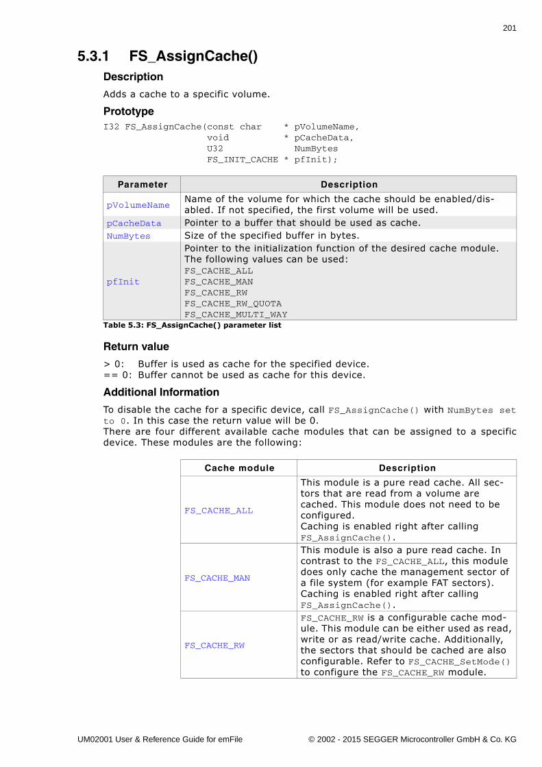
201
5.3.1 FS_AssignCache()Description
Adds a cache to a specific volume.
PrototypeI32 FS_AssignCache(const char * pVolumeName, void * pCacheData, U32 NumBytes FS_INIT_CACHE * pfInit);
Return value
> 0: Buffer is used as cache for the specified device.== 0: Buffer cannot be used as cache for this device.
Additional Information
To disable the cache for a specific device, call FS_AssignCache() with NumBytes setto 0. In this case the return value will be 0.There are four different available cache modules that can be assigned to a specificdevice. These modules are the following:
Parameter Description
pVolumeNameName of the volume for which the cache should be enabled/dis-abled. If not specified, the first volume will be used.
pCacheData Pointer to a buffer that should be used as cache.NumBytes Size of the specified buffer in bytes.
pfInit
Pointer to the initialization function of the desired cache module.The following values can be used:FS_CACHE_ALLFS_CACHE_MANFS_CACHE_RWFS_CACHE_RW_QUOTAFS_CACHE_MULTI_WAY
Table 5.3: FS_AssignCache() parameter list
Cache module Description
FS_CACHE_ALL
This module is a pure read cache. All sec-tors that are read from a volume are cached. This module does not need to be configured.Caching is enabled right after calling FS_AssignCache().
FS_CACHE_MAN
This module is also a pure read cache. In contrast to the FS_CACHE_ALL, this module does only cache the management sector of a file system (for example FAT sectors). Caching is enabled right after calling FS_AssignCache().
FS_CACHE_RW
FS_CACHE_RW is a configurable cache mod-ule. This module can be either used as read, write or as read/write cache. Additionally, the sectors that should be cached are also configurable. Refer to FS_CACHE_SetMode() to configure the FS_CACHE_RW module.
UM02001 User & Reference Guide for emFile © 2002 - 2015 SEGGER Microcontroller GmbH & Co. KG
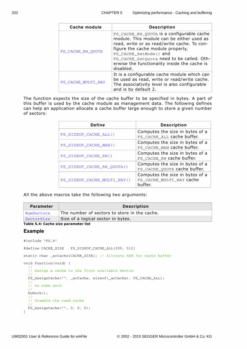
202 CHAPTER 5 Optimizing performance - Caching and buffering
The function expects the size of the cache buffer to be specified in bytes. A part ofthis buffer is used by the cache module as management data. The following definescan help an application allocate a cache buffer large enough to store a given numberof sectors:
All the above macros take the following two arguments:
Example
#include "FS.h"
#define CACHE_SIZE FS_SIZEOF_CACHE_ALL(200, 512)
static char _acCache[CACHE_SIZE]; // Allocate RAM for cache buffer
void Function(void) { // // Assign a cache to the first available device // FS_AssignCache("", _acCache, sizeof(_acCache), FS_CACHE_ALL); // // Do some work // DoWork(); // // Disable the read cache // FS_AssignCache("", 0, 0, 0);}
FS_CACHE_RW_QUOTA
FS_CACHE_RW_QUOTA is a configurable cache module. This module can be either used as read, write or as read/write cache. To con-figure the cache module properly, FS_CACHE_SetMode() and FS_CACHE_SetQuota need to be called. Oth-erwise the functionality inside the cache is disabled.
FS_CACHE_MULTI_WAY
It is a configurable cache module which can be used as read, write or read/write cache. The associativity level is also configurable and is by default 2.
Define Description
FS_SIZEOF_CACHE_ALL()Computes the size in bytes of a FS_CACHE_ALL cache buffer.
FS_SIZEOF_CACHE_MAN()Computes the size in bytes of a FS_CACHE_MAN cache buffer.
FS_SIZEOF_CACHE_RW()Computes the size in bytes of a FS_CACHE_RW cache buffer.
FS_SIZEOF_CACHE_RW_QUOTA()Computes the size in bytes of a FS_CACHE_QUOTA cache buffer.
FS_SIZEOF_CACHE_MULTI_WAY()Computes the size in bytes of a FS_CACHE_MULTI_WAY cache buffer.
Parameter Description
NumSectors The number of sectors to store in the cache.SectorSize Size of a logical sector in bytes.
Table 5.4: Cache size parameter list
Cache module Description
UM02001 User & Reference Guide for emFile © 2002 - 2015 SEGGER Microcontroller GmbH & Co. KG
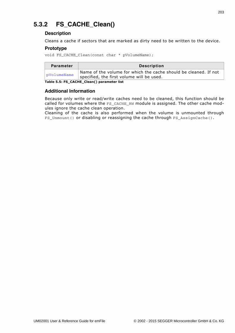
203
5.3.2 FS_CACHE_Clean()Description
Cleans a cache if sectors that are marked as dirty need to be written to the device.
Prototypevoid FS_CACHE_Clean(const char * pVolumeName);
Additional Information
Because only write or read/write caches need to be cleaned, this function should becalled for volumes where the FS_CACHE_RW module is assigned. The other cache mod-ules ignore the cache clean operation.Cleaning of the cache is also performed when the volume is unmounted throughFS_Unmount() or disabling or reassigning the cache through FS_AssignCache().
Parameter Description
pVolumeNameName of the volume for which the cache should be cleaned. If not specified, the first volume will be used.
Table 5.5: FS_CACHE_Clean() parameter list
UM02001 User & Reference Guide for emFile © 2002 - 2015 SEGGER Microcontroller GmbH & Co. KG
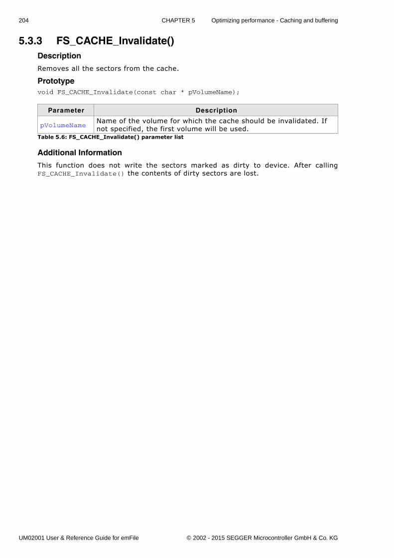
204 CHAPTER 5 Optimizing performance - Caching and buffering
5.3.3 FS_CACHE_Invalidate()Description
Removes all the sectors from the cache.
Prototypevoid FS_CACHE_Invalidate(const char * pVolumeName);
Additional Information
This function does not write the sectors marked as dirty to device. After callingFS_CACHE_Invalidate() the contents of dirty sectors are lost.
Parameter Description
pVolumeNameName of the volume for which the cache should be invalidated. If not specified, the first volume will be used.
Table 5.6: FS_CACHE_Invalidate() parameter list
UM02001 User & Reference Guide for emFile © 2002 - 2015 SEGGER Microcontroller GmbH & Co. KG

205
5.3.4 FS_CACHE_SetAssocLevel()Description
Configures the number of entries (ways) in the cache which can store the contents ofthe same sector.
Prototypeint FS_CACHE_SetAssocLevel(const char * pVolumeName, int AssocLevel);
Return value
== 0 Associativity level configured!= 0 An error occurred
Additional Information
This function makes sense only for FS_CACHE_MULTI_WAY cache modules. Calling thefunction on any other cache module types returns an error. The cache replacementpolicy uses the associativity level to decide where to store the contents of a sector inthe cache. Caches with higher associativity levels tend to have a higher hit rates.
Parameter Description
pVolumeNameName of the volume for which the cache should be configured. If not specified, the first volume will be used.
AssocLevelNumber of entries in the cache as power of 2 (1 for 2-way associa-tive, 2 for 4-way associative, etc.)
Table 5.7: FS_CACHE_SetAssocLevel() parameter list
UM02001 User & Reference Guide for emFile © 2002 - 2015 SEGGER Microcontroller GmbH & Co. KG
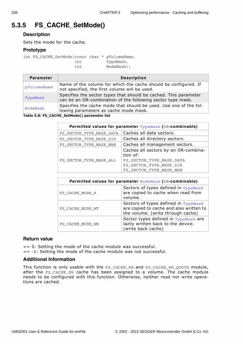
206 CHAPTER 5 Optimizing performance - Caching and buffering
5.3.5 FS_CACHE_SetMode()Description
Sets the mode for the cache.
Prototypeint FS_CACHE_SetMode(const char * pVolumeName, int TypeMask, int ModeMask);
Return value
== 0: Setting the mode of the cache module was successful.== -1: Setting the mode of the cache module was not successful.
Additional Information
This function is only usable with the FS_CACHE_RW and FS_CACHE_RW_QUOTA module,after the FS_CACHE_RW cache has been assigned to a volume. The cache moduleneeds to be configured with this function. Otherwise, neither read nor write opera-tions are cached.
Parameter Description
pVolumeNameName of the volume for which the cache should be configured. If not specified, the first volume will be used.
TypeMaskSpecifies the sector types that should be cached. This parameter can be an OR-combination of the following sector type mask.
ModeMaskSpecifies the cache mode that should be used. Use one of the fol-lowing parameters as cache mode mask.
Table 5.8: FS_CACHE_SetMode() parameter list
Permitted values for parameter TypeMask (OR-combinable)
FS_SECTOR_TYPE_MASK_DATA Caches all data sectors.FS_SECTOR_TYPE_MASK_DIR Caches all directory sectors.FS_SECTOR_TYPE_MASK_MAN Caches all management sectors.
FS_SECTOR_TYPE_MASK_ALL
Caches all sectors by an OR-combina-tion of: FS_SECTOR_TYPE_MASK_DATAFS_SECTOR_TYPE_MASK_DIRFS_SECTOR_TYPE_MASK_MAN
Permitted values for parameter ModeMask (OR-combinable)
FS_CACHE_MODE_RSectors of types defined in TypeMask are copied to cache when read from volume.
FS_CACHE_MODE_WTSectors of types defined in TypeMask are copied to cache and also written to the volume. (write through cache)
FS_CACHE_MODE_WBSector types defined in TypeMask are lazily written back to the device. (write back cache)
UM02001 User & Reference Guide for emFile © 2002 - 2015 SEGGER Microcontroller GmbH & Co. KG
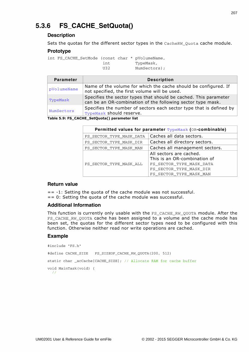
207
5.3.6 FS_CACHE_SetQuota()Description
Sets the quotas for the different sector types in the CacheRW_Quota cache module.
Prototypeint FS_CACHE_SetMode (const char * pVolumeName, int TypeMask, U32 NumSectors);
Return value
== -1: Setting the quota of the cache module was not successful.== 0: Setting the quota of the cache module was successful.
Additional Information
This function is currently only usable with the FS_CACHE_RW_QUOTA module. After theFS_CACHE_RW_QUOTA cache has been assigned to a volume and the cache mode hasbeen set, the quotas for the different sector types need to be configured with thisfunction. Otherwise neither read nor write operations are cached.
Example
#include "FS.h"
#define CACHE_SIZE FS_SIZEOF_CACHE_RW_QUOTA(200, 512)
static char _acCache[CACHE_SIZE]; // Allocate RAM for cache buffer
void MainTask(void) { //
Parameter Description
pVolumeNameName of the volume for which the cache should be configured. If not specified, the first volume will be used.
TypeMaskSpecifies the sector types that should be cached. This parameter can be an OR-combination of the following sector type mask.
NumSectorsSpecifies the number of sectors each sector type that is defined by TypeMask should reserve.
Table 5.9: FS_CACHE_SetQuota() parameter list
Permitted values for parameter TypeMask (OR-combinable)
FS_SECTOR_TYPE_MASK_DATA Caches all data sectors.FS_SECTOR_TYPE_MASK_DIR Caches all directory sectors.FS_SECTOR_TYPE_MASK_MAN Caches all management sectors.
FS_SECTOR_TYPE_MASK_ALL
All sectors are cached. This is an OR-combination of FS_SECTOR_TYPE_MASK_DATAFS_SECTOR_TYPE_MASK_DIRFS_SECTOR_TYPE_MASK_MAN
UM02001 User & Reference Guide for emFile © 2002 - 2015 SEGGER Microcontroller GmbH & Co. KG
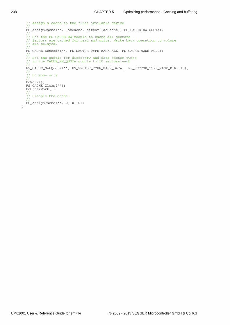
208 CHAPTER 5 Optimizing performance - Caching and buffering
// Assign a cache to the first available device // FS_AssignCache("", _acCache, sizeof(_acCache), FS_CACHE_RW_QUOTA); // // Set the FS_CACHE_RW module to cache all sectors // Sectors are cached for read and write. Write back operation to volume // are delayed. // FS_CACHE_SetMode("", FS_SECTOR_TYPE_MASK_ALL, FS_CACHE_MODE_FULL); // // Set the quotas for directory and data sector types // in the CACHE_RW_QUOTA module to 10 sectors each // FS_CACHE_SetQuota("", FS_SECTOR_TYPE_MASK_DATA | FS_SECTOR_TYPE_MASK_DIR, 10); // // Do some work // DoWork(); FS_CACHE_Clean(""); DoOtherWork(); // // Disable the cache. // FS_AssignCache("", 0, 0, 0);}
UM02001 User & Reference Guide for emFile © 2002 - 2015 SEGGER Microcontroller GmbH & Co. KG
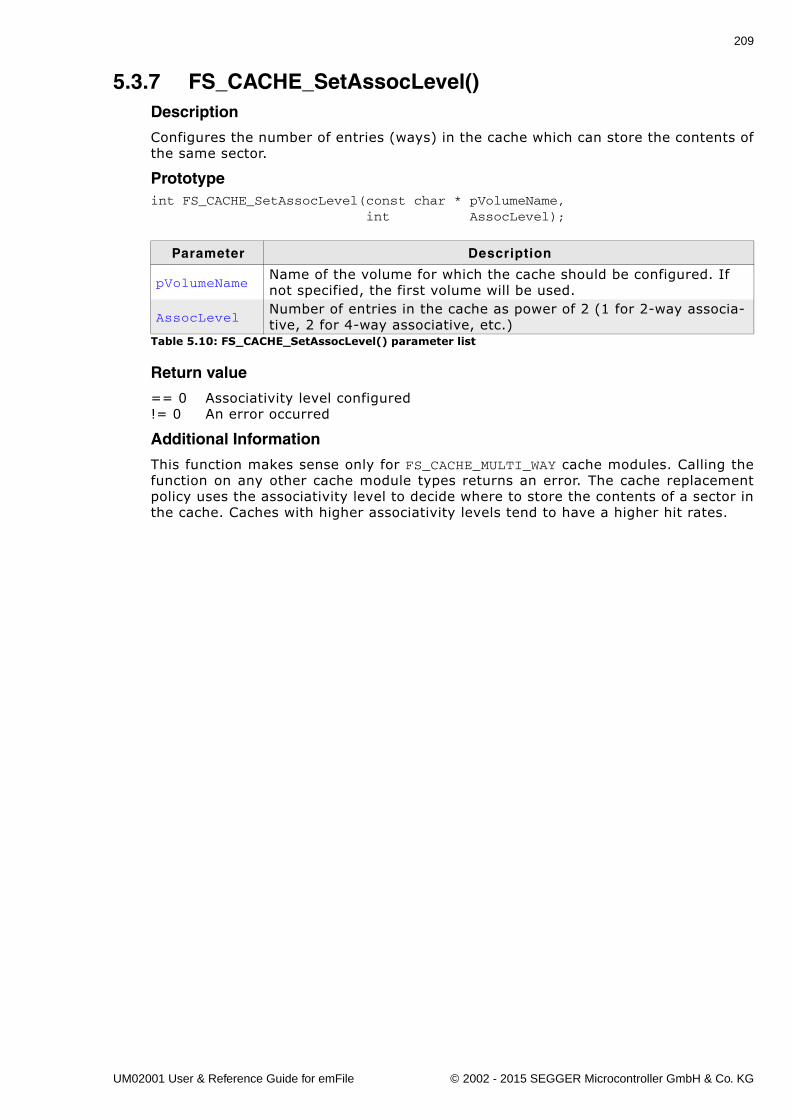
209
5.3.7 FS_CACHE_SetAssocLevel()Description
Configures the number of entries (ways) in the cache which can store the contents ofthe same sector.
Prototypeint FS_CACHE_SetAssocLevel(const char * pVolumeName, int AssocLevel);
Return value
== 0 Associativity level configured!= 0 An error occurred
Additional Information
This function makes sense only for FS_CACHE_MULTI_WAY cache modules. Calling thefunction on any other cache module types returns an error. The cache replacementpolicy uses the associativity level to decide where to store the contents of a sector inthe cache. Caches with higher associativity levels tend to have a higher hit rates.
Parameter Description
pVolumeNameName of the volume for which the cache should be configured. If not specified, the first volume will be used.
AssocLevelNumber of entries in the cache as power of 2 (1 for 2-way associa-tive, 2 for 4-way associative, etc.)
Table 5.10: FS_CACHE_SetAssocLevel() parameter list
UM02001 User & Reference Guide for emFile © 2002 - 2015 SEGGER Microcontroller GmbH & Co. KG
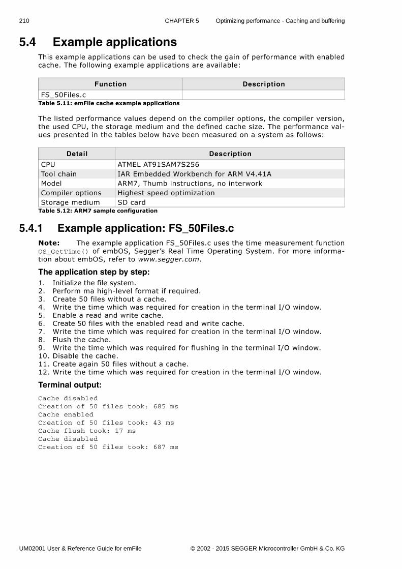
210 CHAPTER 5 Optimizing performance - Caching and buffering
5.4 Example applicationsThis example applications can be used to check the gain of performance with enabledcache. The following example applications are available:
The listed performance values depend on the compiler options, the compiler version,the used CPU, the storage medium and the defined cache size. The performance val-ues presented in the tables below have been measured on a system as follows:
5.4.1 Example application: FS_50Files.cNote: The example application FS_50Files.c uses the time measurement functionOS_GetTime() of embOS, Segger�s Real Time Operating System. For more informa-tion about embOS, refer to www.segger.com.
The application step by step:1. Initialize the file system.2. Perform ma high-level format if required.3. Create 50 files without a cache.4. Write the time which was required for creation in the terminal I/O window.5. Enable a read and write cache.6. Create 50 files with the enabled read and write cache.7. Write the time which was required for creation in the terminal I/O window.8. Flush the cache.9. Write the time which was required for flushing in the terminal I/O window.10. Disable the cache.11. Create again 50 files without a cache.12. Write the time which was required for creation in the terminal I/O window.
Terminal output:
Cache disabledCreation of 50 files took: 685 msCache enabledCreation of 50 files took: 43 msCache flush took: 17 msCache disabledCreation of 50 files took: 687 ms
Function Description
FS_50Files.cTable 5.11: emFile cache example applications
Detail Description
CPU ATMEL AT91SAM7S256Tool chain IAR Embedded Workbench for ARM V4.41AModel ARM7, Thumb instructions, no interworkCompiler options Highest speed optimizationStorage medium SD card
Table 5.12: ARM7 sample configuration
UM02001 User & Reference Guide for emFile © 2002 - 2015 SEGGER Microcontroller GmbH & Co. KG
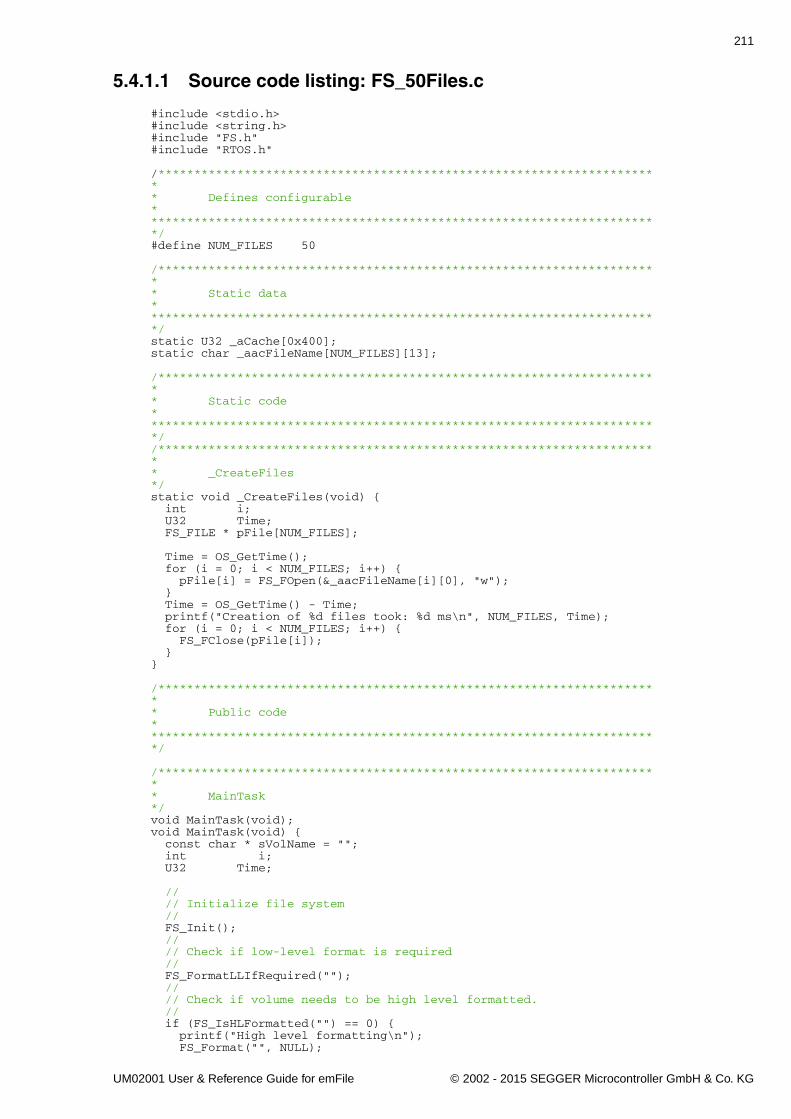
211
5.4.1.1 Source code listing: FS_50Files.c
#include <stdio.h>#include <string.h>#include "FS.h"#include "RTOS.h"
/*********************************************************************** Defines configurable************************************************************************/#define NUM_FILES 50
/*********************************************************************** Static data************************************************************************/static U32 _aCache[0x400];static char _aacFileName[NUM_FILES][13];
/*********************************************************************** Static code************************************************************************//*********************************************************************** _CreateFiles*/static void _CreateFiles(void) { int i; U32 Time; FS_FILE * pFile[NUM_FILES];
Time = OS_GetTime(); for (i = 0; i < NUM_FILES; i++) { pFile[i] = FS_FOpen(&_aacFileName[i][0], "w"); } Time = OS_GetTime() - Time; printf("Creation of %d files took: %d ms\n", NUM_FILES, Time); for (i = 0; i < NUM_FILES; i++) { FS_FClose(pFile[i]); }}
/*********************************************************************** Public code************************************************************************/
/*********************************************************************** MainTask*/void MainTask(void);void MainTask(void) { const char * sVolName = ""; int i; U32 Time;
// // Initialize file system // FS_Init(); // // Check if low-level format is required // FS_FormatLLIfRequired(""); // // Check if volume needs to be high level formatted. // if (FS_IsHLFormatted("") == 0) { printf("High level formatting\n"); FS_Format("", NULL);
UM02001 User & Reference Guide for emFile © 2002 - 2015 SEGGER Microcontroller GmbH & Co. KG
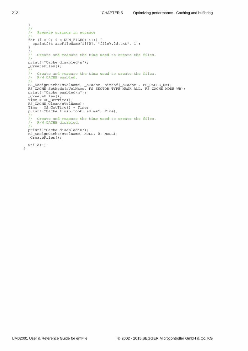
212 CHAPTER 5 Optimizing performance - Caching and buffering
} // // Prepare strings in advance // for (i = 0; i < NUM_FILES; i++) { sprintf(&_aacFileName[i][0], "file%.2d.txt", i); } // // Create and measure the time used to create the files. // printf("Cache disabled\n"); _CreateFiles(); // // Create and measure the time used to create the files. // R/W CACHE enabled. // FS_AssignCache(sVolName, _aCache, sizeof(_aCache), FS_CACHE_RW); FS_CACHE_SetMode(sVolName, FS_SECTOR_TYPE_MASK_ALL, FS_CACHE_MODE_WB); printf("Cache enabled\n"); _CreateFiles(); Time = OS_GetTime(); FS_CACHE_Clean(sVolName); Time = OS_GetTime() - Time; printf("Cache flush took: %d ms", Time); // // Create and measure the time used to create the files. // R/W CACHE disabled. // printf("Cache disabled\n"); FS_AssignCache(sVolName, NULL, 0, NULL); _CreateFiles();
while(1);}
UM02001 User & Reference Guide for emFile © 2002 - 2015 SEGGER Microcontroller GmbH & Co. KG
213
Chapter 6
Device drivers
emFile has been designed to cooperate with any kind of hardware. To use specifichardware with emFile, a so-called device driver for that hardware is required. Thedevice driver consists of basic I/O functions for accessing the hardware and a globaltable that holds pointers to these functions.
UM02001 User & Reference Guide for emFile © 2002 - 2015 SEGGER Microcontroller GmbH & Co. KG
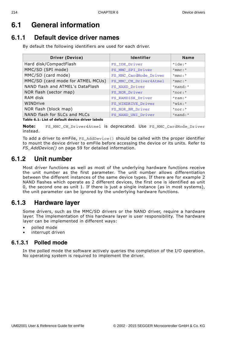
214 CHAPTER 6 Device drivers
6.1 General information
6.1.1 Default device driver namesBy default the following identifiers are used for each driver.
Note: FS_MMC_CM_Driver4Atmel is deprecated. Use FS_MMC_CardMode_Driverinstead.
To add a driver to emFile, FS_AddDevice() should be called with the proper identifierto mount the device driver to emFile before accessing the device or its units. Refer toFS_AddDevice() on page 59 for detailed information.
6.1.2 Unit numberMost driver functions as well as most of the underlying hardware functions receivethe unit number as the first parameter. The unit number allows differentiationbetween the different instances of the same device types. If there are for example 2NAND flashes which operate as 2 different devices, the first one is identified as unit0, the second one as unit 1. If there is just a single instance (as in most systems),the unit parameter can be ignored by the underlying hardware functions.
6.1.3 Hardware layerSome drivers, such as the MMC/SD drivers or the NAND driver, require a hardwarelayer. The implementation of this hardware layer is user responsibility. The hardwarelayer can be implemented in different ways:
� polled mode� interrupt driven
6.1.3.1 Polled modeIn the polled mode the software actively queries the completion of the I/O operation.No operating system is required to implement the driver.
Driver (Device) Identifier Name
Hard disk/CompactFlash FS_IDE_Driver "ide:"
MMC/SD (SPI mode) FS_MMC_SPI_Driver "mmc:"
MMC/SD (card mode) FS_MMC_CardMode_Driver "mmc:"
MMC/SD (card mode for ATMEL MCUs) FS_MMC_CM_Driver4Atmel "mmc:"
NAND flash and ATMEL's DataFlash FS_NAND_Driver "nand:"
NOR flash (sector map) FS_NOR_Driver "nor:"
RAM disk FS_RAMDISK_Driver "ram:"
WINDrive FS_WINDRIVE_Driver "win:"
NOR flash (block map) FS_NOR_BM_Driver "nor:"
NAND flash for SLCs and MLCs FS_NAND_UNI_Driver "nand:"Table 6.1: List of default device driver labels
UM02001 User & Reference Guide for emFile © 2002 - 2015 SEGGER Microcontroller GmbH & Co. KG
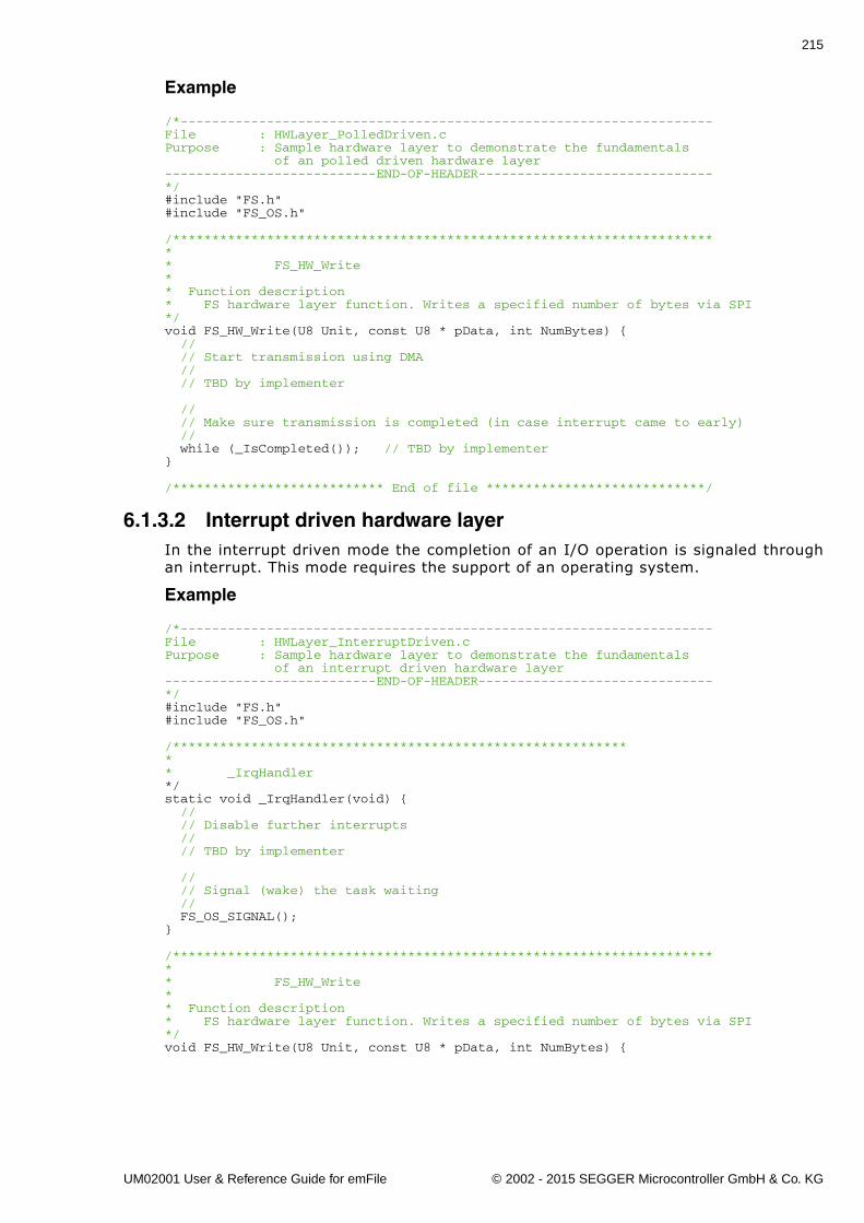
215
Example
/*--------------------------------------------------------------------File : HWLayer_PolledDriven.cPurpose : Sample hardware layer to demonstrate the fundamentals of an polled driven hardware layer---------------------------END-OF-HEADER------------------------------*/#include "FS.h"#include "FS_OS.h"
/*********************************************************************** FS_HW_Write** Function description* FS hardware layer function. Writes a specified number of bytes via SPI*/void FS_HW_Write(U8 Unit, const U8 * pData, int NumBytes) { // // Start transmission using DMA // // TBD by implementer
// // Make sure transmission is completed (in case interrupt came to early) // while (_IsCompleted()); // TBD by implementer}
/*************************** End of file ****************************/
6.1.3.2 Interrupt driven hardware layerIn the interrupt driven mode the completion of an I/O operation is signaled throughan interrupt. This mode requires the support of an operating system.
Example
/*--------------------------------------------------------------------File : HWLayer_InterruptDriven.cPurpose : Sample hardware layer to demonstrate the fundamentals of an interrupt driven hardware layer---------------------------END-OF-HEADER------------------------------*/#include "FS.h"#include "FS_OS.h"
/************************************************************ _IrqHandler*/static void _IrqHandler(void) { // // Disable further interrupts // // TBD by implementer
// // Signal (wake) the task waiting // FS_OS_SIGNAL();}
/*********************************************************************** FS_HW_Write** Function description* FS hardware layer function. Writes a specified number of bytes via SPI*/void FS_HW_Write(U8 Unit, const U8 * pData, int NumBytes) {
UM02001 User & Reference Guide for emFile © 2002 - 2015 SEGGER Microcontroller GmbH & Co. KG
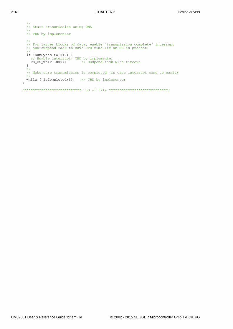
216 CHAPTER 6 Device drivers
// // Start transmission using DMA // // TBD by implementer
// // For larger blocks of data, enable "transmission complete" interrupt // and suspend task to save CPU time (if an OS is present) // if (NumBytes >= 512) { // Enable interrupt: TBD by implementer FS_OS_WAIT(1000); // Suspend task with timeout } // // Make sure transmission is completed (in case interrupt came to early) // while (_IsCompleted()); // TBD by implementer}
/*************************** End of file ****************************/
UM02001 User & Reference Guide for emFile © 2002 - 2015 SEGGER Microcontroller GmbH & Co. KG

217
6.2 RAM disk driveremFile comes with a simple RAM disk driver that makes it possible to use a portion ofyour system RAM as drive for data storage. This can be very helpful to examine yoursystem performance and may also be used as a in-system test procedure.
6.2.1 Supported hardwareThe RAM driver can be used with every target with enough RAM. The size of the diskis defined as the number of sectors reserved for the drive.
6.2.2 Theory of operationA RAM disk is a portion of memory that you allocate to use as a partition. The RAMdisk driver takes some of your memory and pretends that it is a hard drive that youcan format, mount, save files to, etc.
Remember that every bit of RAM is important for the well being of your system andthe bigger your RAM disk is, the less memory there is available for your system.
6.2.3 Fail-safe operationWhen power is lost, the data of the RAM drive is typically lost as well except for sys-tems with Battery backup for the RAM used as storage device.
For this reason, fail-safety is relevant only for systems which provide such batterybackup.
Unexpected Reset
In case of an unexpected reset the data will be preserved. However, if the Power fail-ure / unexpected Reset interrupts a write operation, the data of the sector may con-tain partially invalid data.
Power failure
Power failure causes an unexpected reset and has the same effects.
6.2.4 Wear levelingThe RAM disk driver does not require wear leveling.
UM02001 User & Reference Guide for emFile © 2002 - 2015 SEGGER Microcontroller GmbH & Co. KG
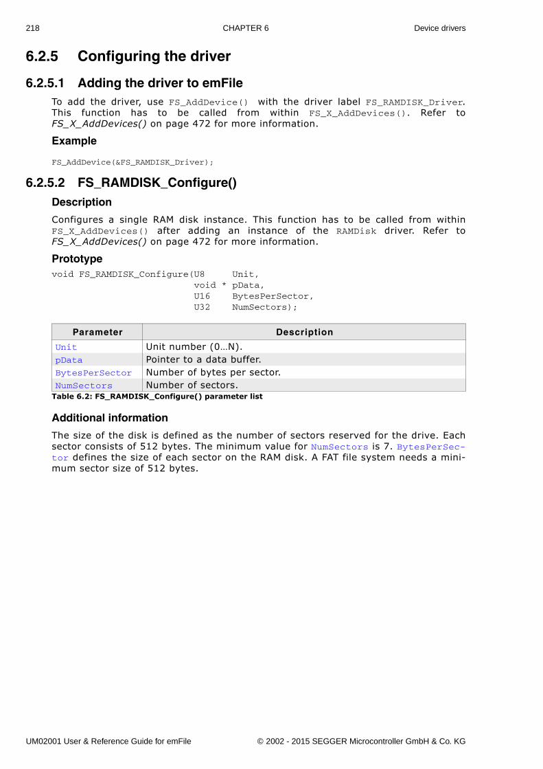
218 CHAPTER 6 Device drivers
6.2.5 Configuring the driver
6.2.5.1 Adding the driver to emFileTo add the driver, use FS_AddDevice() with the driver label FS_RAMDISK_Driver.This function has to be called from within FS_X_AddDevices(). Refer toFS_X_AddDevices() on page 472 for more information.
Example
FS_AddDevice(&FS_RAMDISK_Driver);
6.2.5.2 FS_RAMDISK_Configure()Description
Configures a single RAM disk instance. This function has to be called from withinFS_X_AddDevices() after adding an instance of the RAMDisk driver. Refer toFS_X_AddDevices() on page 472 for more information.
Prototypevoid FS_RAMDISK_Configure(U8 Unit, void * pData, U16 BytesPerSector, U32 NumSectors);
Additional information
The size of the disk is defined as the number of sectors reserved for the drive. Eachsector consists of 512 bytes. The minimum value for NumSectors is 7. BytesPerSec-tor defines the size of each sector on the RAM disk. A FAT file system needs a mini-mum sector size of 512 bytes.
Parameter Description
Unit Unit number (0�N).pData Pointer to a data buffer.BytesPerSector Number of bytes per sector.NumSectors Number of sectors.
Table 6.2: FS_RAMDISK_Configure() parameter list
UM02001 User & Reference Guide for emFile © 2002 - 2015 SEGGER Microcontroller GmbH & Co. KG
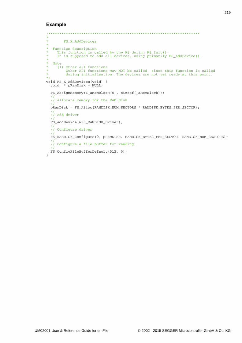
219
Example
/*********************************************************************** FS_X_AddDevices** Function description* This function is called by the FS during FS_Init().* It is supposed to add all devices, using primarily FS_AddDevice().* * Note* (1) Other API functions* Other API functions may NOT be called, since this function is called* during initialisation. The devices are not yet ready at this point.*/void FS_X_AddDevices(void) { void * pRamDisk = NULL;
FS_AssignMemory(&_aMemBlock[0], sizeof(_aMemBlock)); // // Allocate memory for the RAM disk // pRamDisk = FS_Alloc(RAMDISK_NUM_SECTORS * RAMDISK_BYTES_PER_SECTOR); // // Add driver // FS_AddDevice(&FS_RAMDISK_Driver); // // Configure driver // FS_RAMDISK_Configure(0, pRamDisk, RAMDISK_BYTES_PER_SECTOR, RAMDISK_NUM_SECTORS); // // Configure a file buffer for reading. // FS_ConfigFileBufferDefault(512, 0);}
UM02001 User & Reference Guide for emFile © 2002 - 2015 SEGGER Microcontroller GmbH & Co. KG
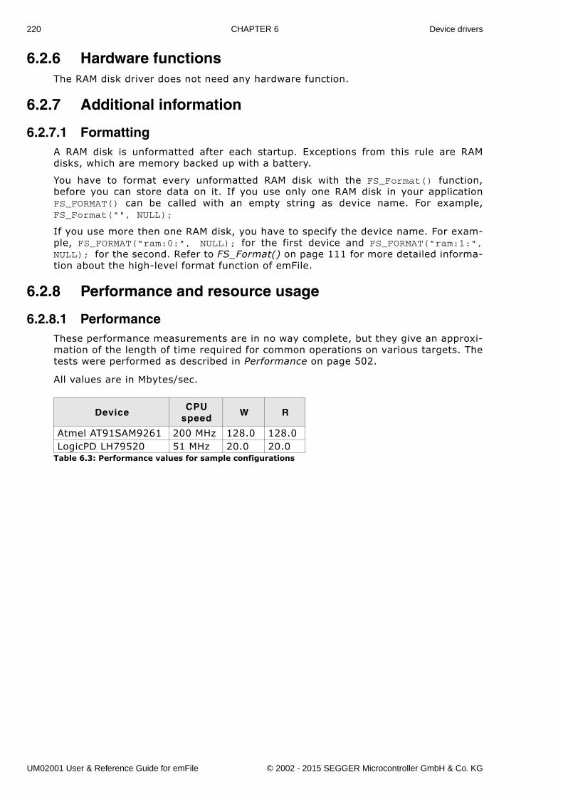
220 CHAPTER 6 Device drivers
6.2.6 Hardware functionsThe RAM disk driver does not need any hardware function.
6.2.7 Additional information
6.2.7.1 FormattingA RAM disk is unformatted after each startup. Exceptions from this rule are RAMdisks, which are memory backed up with a battery.
You have to format every unformatted RAM disk with the FS_Format() function,before you can store data on it. If you use only one RAM disk in your applicationFS_FORMAT() can be called with an empty string as device name. For example,FS_Format("", NULL);
If you use more then one RAM disk, you have to specify the device name. For exam-ple, FS_FORMAT("ram:0:", NULL); for the first device and FS_FORMAT("ram:1:",NULL); for the second. Refer to FS_Format() on page 111 for more detailed informa-tion about the high-level format function of emFile.
6.2.8 Performance and resource usage
6.2.8.1 PerformanceThese performance measurements are in no way complete, but they give an approxi-mation of the length of time required for common operations on various targets. Thetests were performed as described in Performance on page 502.
All values are in Mbytes/sec.
DeviceCPU
speedW R
Atmel AT91SAM9261 200 MHz 128.0 128.0LogicPD LH79520 51 MHz 20.0 20.0
Table 6.3: Performance values for sample configurations
UM02001 User & Reference Guide for emFile © 2002 - 2015 SEGGER Microcontroller GmbH & Co. KG
221
6.3 NAND flash driveremFile supports the use of NAND flashes. Two optional drivers for NAND flashes areavailable:
� SLC1 driver - works only with SLC flashes which require 1-bit error correction. Italso supports the ATMEL�s DataFlashes.
� Universal driver - works with all modern SLC and MLC NAND flashes. It can usethe ECC engine build into NAND flashes to correct bit errors.
To use the drivers in your system, you will have to provide basic I/O functions foraccessing your flash device.
How to select which driver to use
The first factor is the type of device used. ATMEL�s DataFlashes are supported only bythe SLC1 driver. NAND flashes are supported by both drivers.
The bit error correction requirements of the NAND flash is the next factor. It indicateshow many bit errors the error correcting code (ECC) must be able to detect and cor-rect. If the NAND flash requires only 1-bit correction capability then the SLC1 drivercan be used. The SLC1 driver will perform the bit error detection and correction. Formore than 1-bit correction capability the Universal driver is required. In order to usethe Universal driver, the following conditions must be met:
� Page size of minimum 2048 bytes. More specifically: the size spare area corresponding to 512 bytes in the data areamust be greater than 16. For more information about the internals of a NANDflash, refer to NAND flash organization on page 222.
� Hardware support for error correction.Either a NAND flash with internal ECC engine or another way to compute the ECCin hardware (MCU, FPGA, etc.)
� The ECC must not exceed 8 bytes in size.
Multiple driver configuration
Both drivers store management information to spare area of a page. The layout andthe content of this information is different for each driver which means that datawritten using one driver is not recognized when read using the other one. If an appli-cation used the SLC1 driver to write to NAND flash it can not use the Universal driverto access it. The application should decide at runtime in the FS_X_AddDevices()function which driver to configure. emFile supports the configuration of a driverbased on the type of NAND flash connected to host. For an example, refer toFS_NAND_PHY_ReadDeviceId() on page 308.
UM02001 User & Reference Guide for emFile © 2002 - 2015 SEGGER Microcontroller GmbH & Co. KG
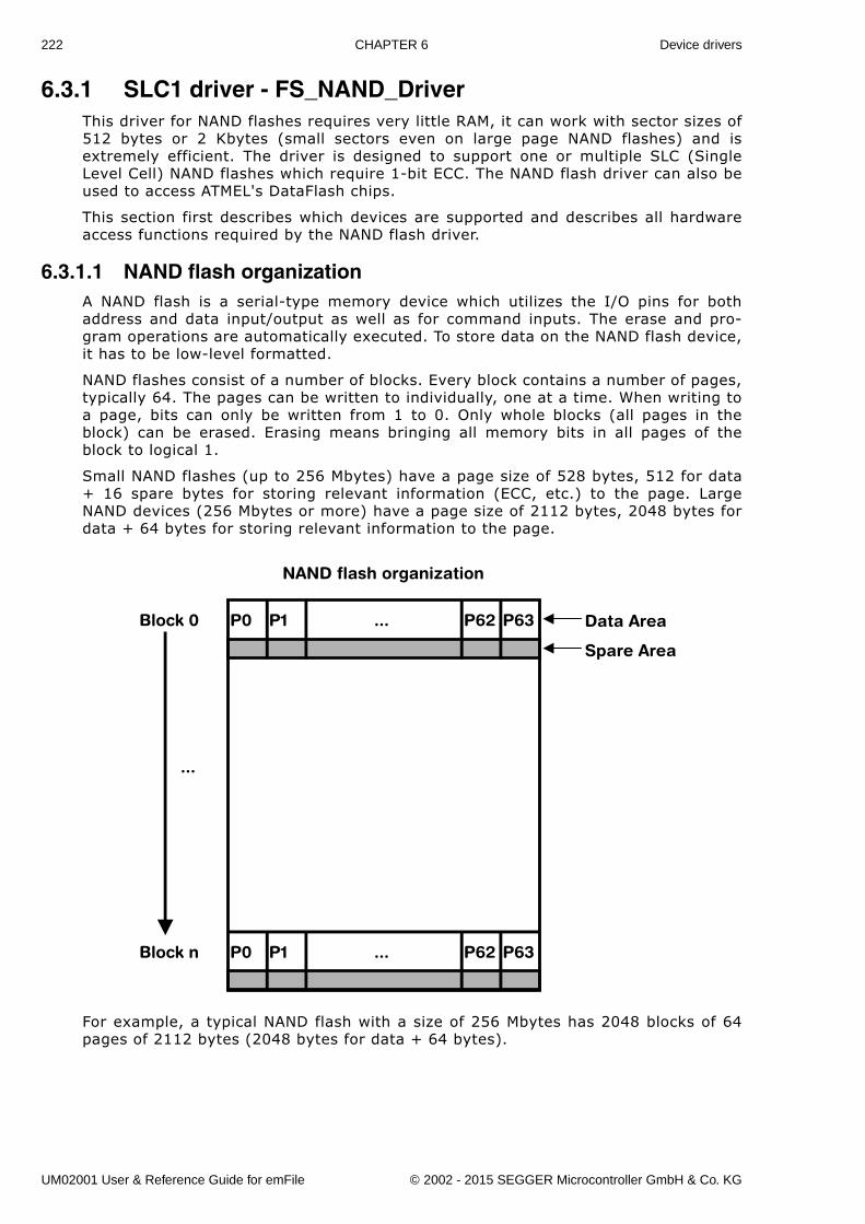
222 CHAPTER 6 Device drivers
6.3.1 SLC1 driver - FS_NAND_DriverThis driver for NAND flashes requires very little RAM, it can work with sector sizes of512 bytes or 2 Kbytes (small sectors even on large page NAND flashes) and isextremely efficient. The driver is designed to support one or multiple SLC (SingleLevel Cell) NAND flashes which require 1-bit ECC. The NAND flash driver can also beused to access ATMEL's DataFlash chips.
This section first describes which devices are supported and describes all hardwareaccess functions required by the NAND flash driver.
6.3.1.1 NAND flash organizationA NAND flash is a serial-type memory device which utilizes the I/O pins for bothaddress and data input/output as well as for command inputs. The erase and pro-gram operations are automatically executed. To store data on the NAND flash device,it has to be low-level formatted.
NAND flashes consist of a number of blocks. Every block contains a number of pages,typically 64. The pages can be written to individually, one at a time. When writing toa page, bits can only be written from 1 to 0. Only whole blocks (all pages in theblock) can be erased. Erasing means bringing all memory bits in all pages of theblock to logical 1.
Small NAND flashes (up to 256 Mbytes) have a page size of 528 bytes, 512 for data+ 16 spare bytes for storing relevant information (ECC, etc.) to the page. LargeNAND devices (256 Mbytes or more) have a page size of 2112 bytes, 2048 bytes fordata + 64 bytes for storing relevant information to the page.
For example, a typical NAND flash with a size of 256 Mbytes has 2048 blocks of 64pages of 2112 bytes (2048 bytes for data + 64 bytes).
P0 P1 P63P62
P0 P1 P63P62
...
...
Block 0
Block n
Data Area
Spare Area
NAND flash organization
...
UM02001 User & Reference Guide for emFile © 2002 - 2015 SEGGER Microcontroller GmbH & Co. KG
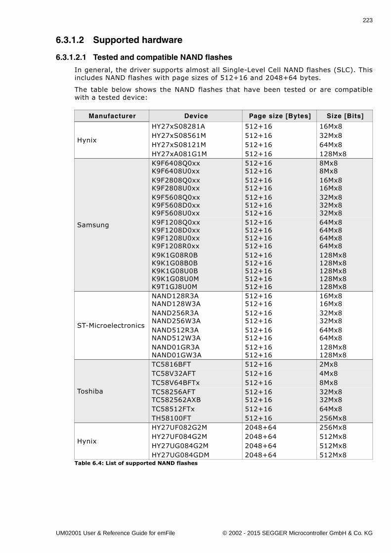
223
6.3.1.2 Supported hardware
6.3.1.2.1 Tested and compatible NAND flashes
In general, the driver supports almost all Single-Level Cell NAND flashes (SLC). Thisincludes NAND flashes with page sizes of 512+16 and 2048+64 bytes.
The table below shows the NAND flashes that have been tested or are compatiblewith a tested device:
Manufacturer Device Page size [Bytes] Size [Bits]
Hynix
HY27xS08281A 512+16 16Mx8HY27xS08561M 512+16 32Mx8HY27xS08121M 512+16 64Mx8HY27xA081G1M 512+16 128Mx8
Samsung
K9F6408Q0xxK9F6408U0xx
512+16512+16
8Mx88Mx8
K9F2808Q0xxK9F2808U0xx
512+16512+16
16Mx816Mx8
K9F5608Q0xxK9F5608D0xxK9F5608U0xx
512+16512+16512+16
32Mx832Mx832Mx8
K9F1208Q0xxK9F1208D0xxK9F1208U0xxK9F1208R0xx
512+16512+16512+16512+16
64Mx864Mx864Mx864Mx8
K9K1G08R0BK9K1G08B0BK9K1G08U0BK9K1G08U0MK9T1GJ8U0M
512+16512+16512+16512+16512+16
128Mx8128Mx8128Mx8128Mx8128Mx8
ST-Microelectronics
NAND128R3ANAND128W3A
512+16512+16
16Mx816Mx8
NAND256R3ANAND256W3A
512+16512+16
32Mx832Mx8
NAND512R3ANAND512W3A
512+16512+16
64Mx864Mx8
NAND01GR3ANAND01GW3A
512+16512+16
128Mx8128Mx8
Toshiba
TC5816BFT 512+16 2Mx8TC58V32AFT 512+16 4Mx8TC58V64BFTx 512+16 8Mx8TC58256AFTTC582562AXB
512+16512+16
32Mx832Mx8
TC58512FTx 512+16 64Mx8TH58100FT 512+16 256Mx8
Hynix
HY27UF082G2M 2048+64 256Mx8HY27UF084G2M 2048+64 512Mx8HY27UG084G2M 2048+64 512Mx8HY27UG084GDM 2048+64 512Mx8
Table 6.4: List of supported NAND flashes
UM02001 User & Reference Guide for emFile © 2002 - 2015 SEGGER Microcontroller GmbH & Co. KG
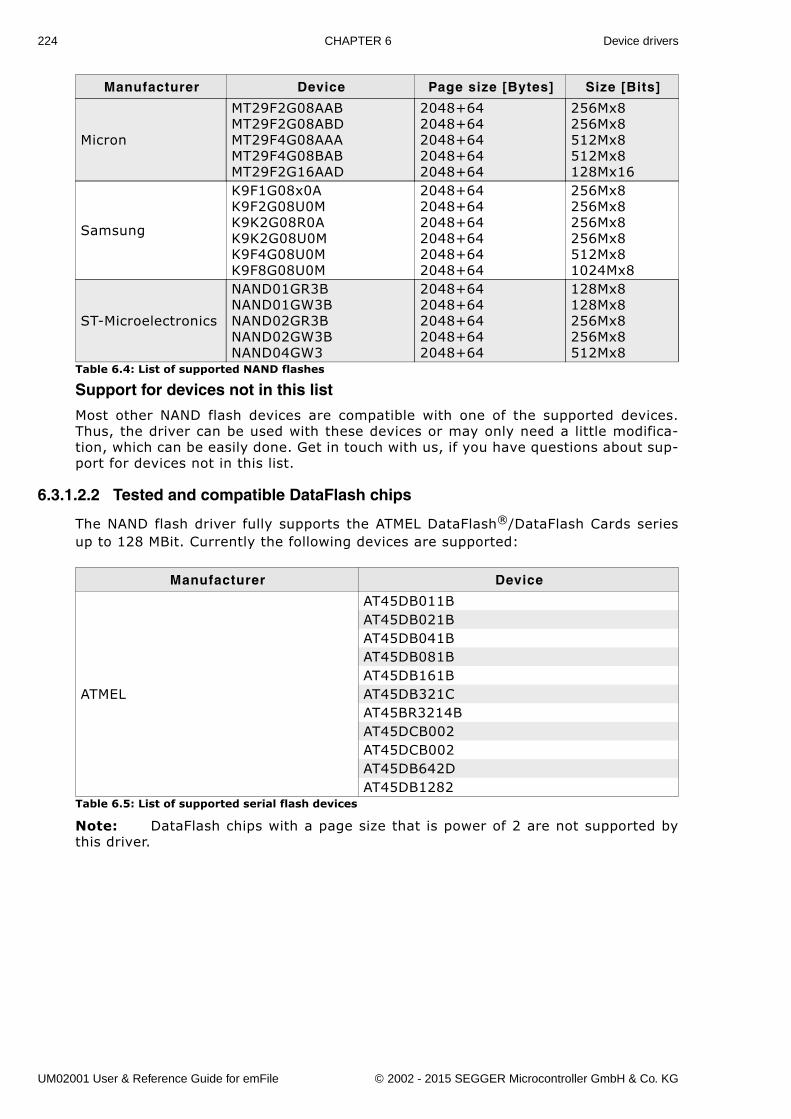
224 CHAPTER 6 Device drivers
Support for devices not in this list
Most other NAND flash devices are compatible with one of the supported devices.Thus, the driver can be used with these devices or may only need a little modifica-tion, which can be easily done. Get in touch with us, if you have questions about sup-port for devices not in this list.
6.3.1.2.2 Tested and compatible DataFlash chips
The NAND flash driver fully supports the ATMEL DataFlash®/DataFlash Cards seriesup to 128 MBit. Currently the following devices are supported:
Note: DataFlash chips with a page size that is power of 2 are not supported bythis driver.
Micron
MT29F2G08AABMT29F2G08ABDMT29F4G08AAAMT29F4G08BABMT29F2G16AAD
2048+642048+642048+642048+642048+64
256Mx8256Mx8512Mx8512Mx8128Mx16
Samsung
K9F1G08x0AK9F2G08U0MK9K2G08R0AK9K2G08U0MK9F4G08U0MK9F8G08U0M
2048+642048+642048+642048+642048+642048+64
256Mx8256Mx8256Mx8256Mx8512Mx81024Mx8
ST-Microelectronics
NAND01GR3BNAND01GW3BNAND02GR3BNAND02GW3BNAND04GW3
2048+642048+642048+642048+642048+64
128Mx8128Mx8256Mx8256Mx8512Mx8
Manufacturer Device
ATMEL
AT45DB011BAT45DB021BAT45DB041BAT45DB081BAT45DB161BAT45DB321CAT45BR3214BAT45DCB002AT45DCB002AT45DB642DAT45DB1282
Table 6.5: List of supported serial flash devices
Manufacturer Device Page size [Bytes] Size [Bits]
Table 6.4: List of supported NAND flashes
UM02001 User & Reference Guide for emFile © 2002 - 2015 SEGGER Microcontroller GmbH & Co. KG
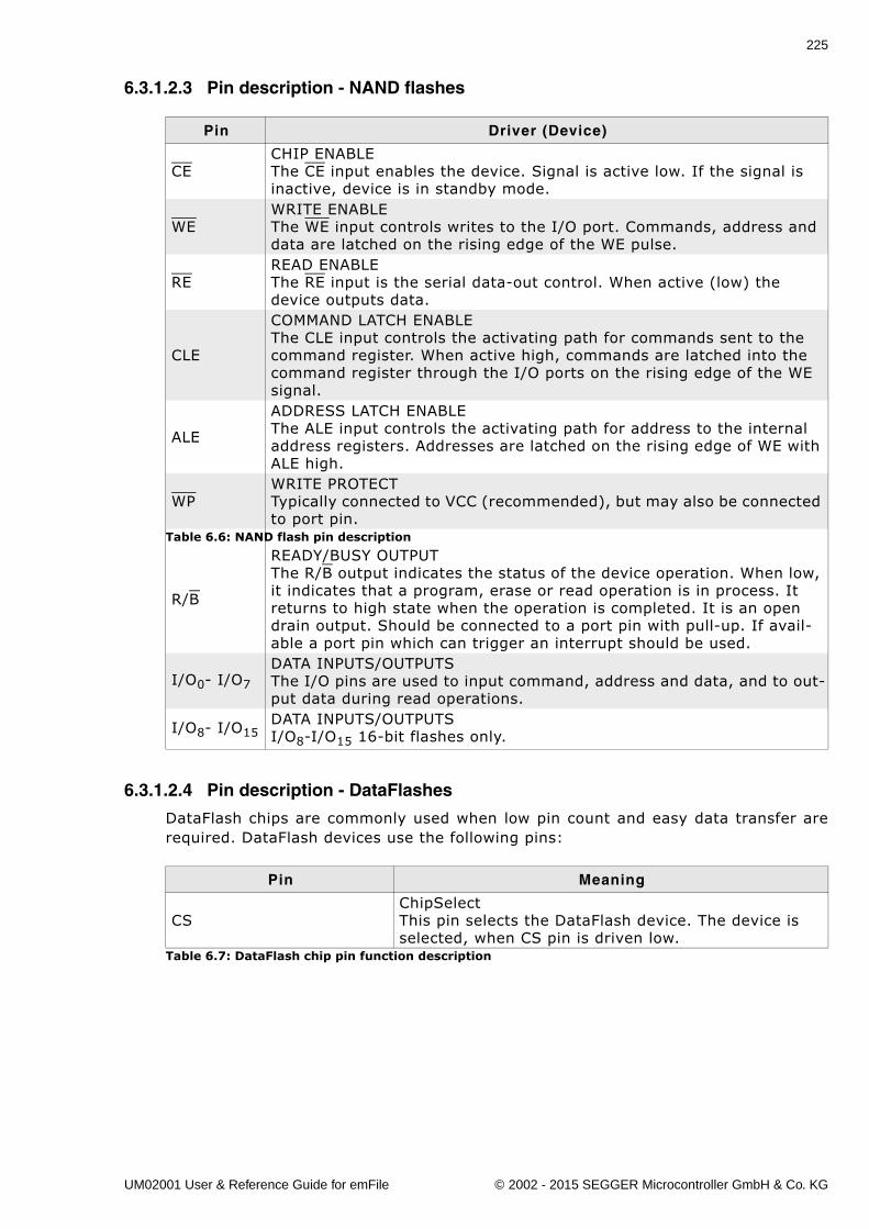
225
6.3.1.2.3 Pin description - NAND flashes
6.3.1.2.4 Pin description - DataFlashes
DataFlash chips are commonly used when low pin count and easy data transfer arerequired. DataFlash devices use the following pins:
Pin Driver (Device)
CECHIP ENABLEThe CE input enables the device. Signal is active low. If the signal is inactive, device is in standby mode.
WEWRITE ENABLEThe WE input controls writes to the I/O port. Commands, address and data are latched on the rising edge of the WE pulse.
REREAD ENABLEThe RE input is the serial data-out control. When active (low) the device outputs data.
CLE
COMMAND LATCH ENABLEThe CLE input controls the activating path for commands sent to the command register. When active high, commands are latched into the command register through the I/O ports on the rising edge of the WE signal.
ALE
ADDRESS LATCH ENABLEThe ALE input controls the activating path for address to the internal address registers. Addresses are latched on the rising edge of WE with ALE high.
WPWRITE PROTECTTypically connected to VCC (recommended), but may also be connected to port pin.
R/B
READY/BUSY OUTPUTThe R/B output indicates the status of the device operation. When low, it indicates that a program, erase or read operation is in process. It returns to high state when the operation is completed. It is an open drain output. Should be connected to a port pin with pull-up. If avail-able a port pin which can trigger an interrupt should be used.
I/O0- I/O7
DATA INPUTS/OUTPUTSThe I/O pins are used to input command, address and data, and to out-put data during read operations.
I/O8- I/O15DATA INPUTS/OUTPUTSI/O8-I/O15 16-bit flashes only.
Table 6.6: NAND flash pin description
Pin Meaning
CSChipSelectThis pin selects the DataFlash device. The device is selected, when CS pin is driven low.
Table 6.7: DataFlash chip pin function description
UM02001 User & Reference Guide for emFile © 2002 - 2015 SEGGER Microcontroller GmbH & Co. KG
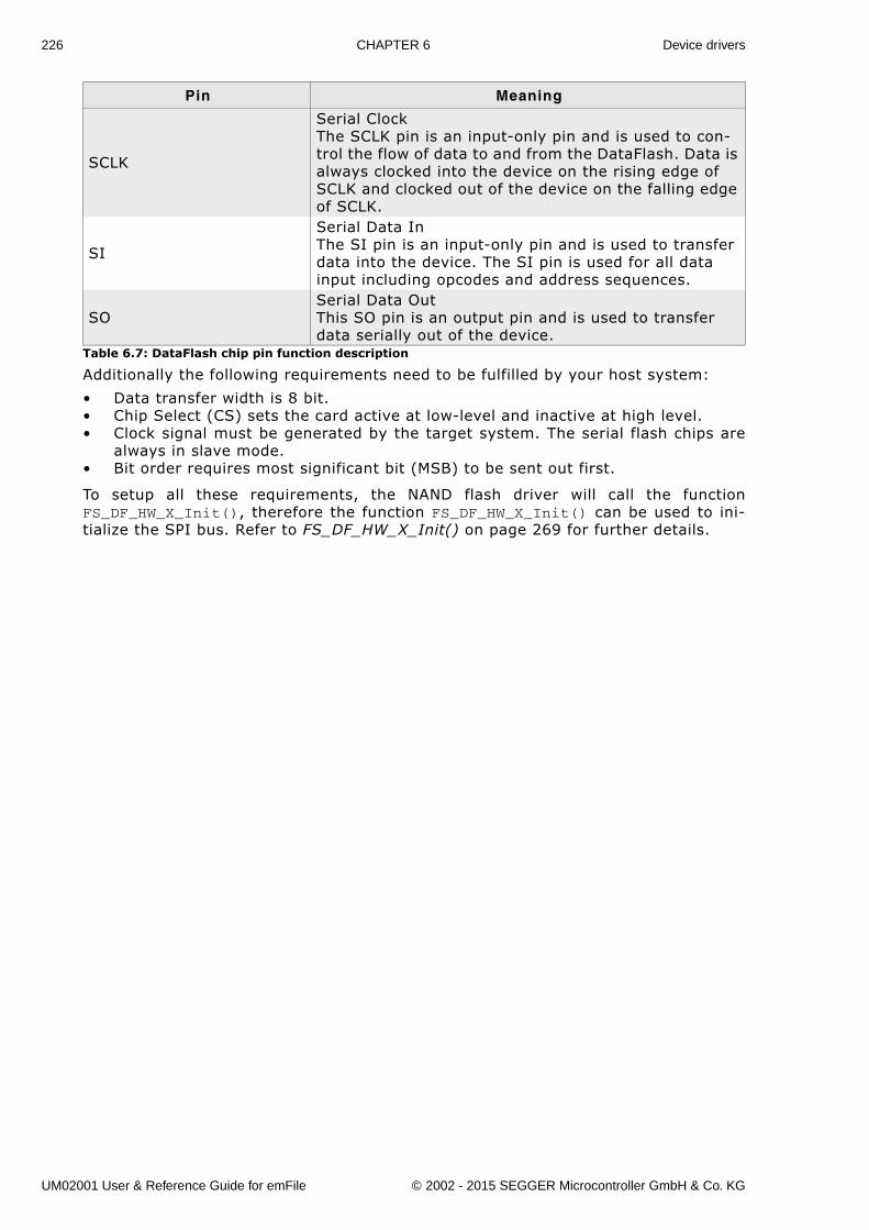
226 CHAPTER 6 Device drivers
Additionally the following requirements need to be fulfilled by your host system:
� Data transfer width is 8 bit.� Chip Select (CS) sets the card active at low-level and inactive at high level.� Clock signal must be generated by the target system. The serial flash chips are
always in slave mode.� Bit order requires most significant bit (MSB) to be sent out first.
To setup all these requirements, the NAND flash driver will call the functionFS_DF_HW_X_Init(), therefore the function FS_DF_HW_X_Init() can be used to ini-tialize the SPI bus. Refer to FS_DF_HW_X_Init() on page 269 for further details.
SCLK
Serial ClockThe SCLK pin is an input-only pin and is used to con-trol the flow of data to and from the DataFlash. Data is always clocked into the device on the rising edge of SCLK and clocked out of the device on the falling edge of SCLK.
SI
Serial Data InThe SI pin is an input-only pin and is used to transfer data into the device. The SI pin is used for all data input including opcodes and address sequences.
SOSerial Data OutThis SO pin is an output pin and is used to transfer data serially out of the device.
Pin Meaning
Table 6.7: DataFlash chip pin function description
UM02001 User & Reference Guide for emFile © 2002 - 2015 SEGGER Microcontroller GmbH & Co. KG
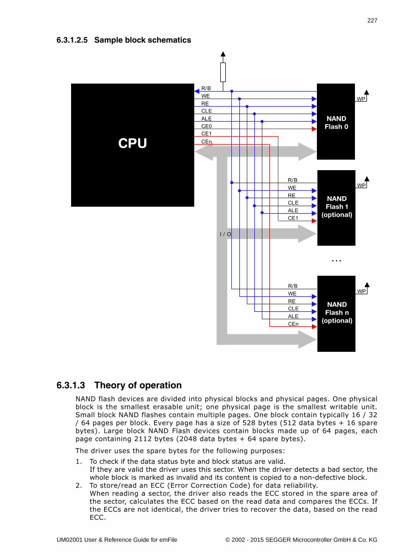
227
6.3.1.2.5 Sample block schematics
6.3.1.3 Theory of operationNAND flash devices are divided into physical blocks and physical pages. One physicalblock is the smallest erasable unit; one physical page is the smallest writable unit.Small block NAND flashes contain multiple pages. One block contain typically 16 / 32/ 64 pages per block. Every page has a size of 528 bytes (512 data bytes + 16 sparebytes). Large block NAND Flash devices contain blocks made up of 64 pages, eachpage containing 2112 bytes (2048 data bytes + 64 spare bytes).
The driver uses the spare bytes for the following purposes:
1. To check if the data status byte and block status are valid.If they are valid the driver uses this sector. When the driver detects a bad sector, thewhole block is marked as invalid and its content is copied to a non-defective block.
2. To store/read an ECC (Error Correction Code) for data reliability.When reading a sector, the driver also reads the ECC stored in the spare area ofthe sector, calculates the ECC based on the read data and compares the ECCs. Ifthe ECCs are not identical, the driver tries to recover the data, based on the readECC.
NANDFlash 1
(optional)
WP
NANDFlash 0
R/BWERECLEALECE0CE1
R/BWERECLEALECE1
WP
CPU
NANDFlash n
(optional)
WPR/BWERECLEALECEn
I / O
CEn
...
UM02001 User & Reference Guide for emFile © 2002 - 2015 SEGGER Microcontroller GmbH & Co. KG
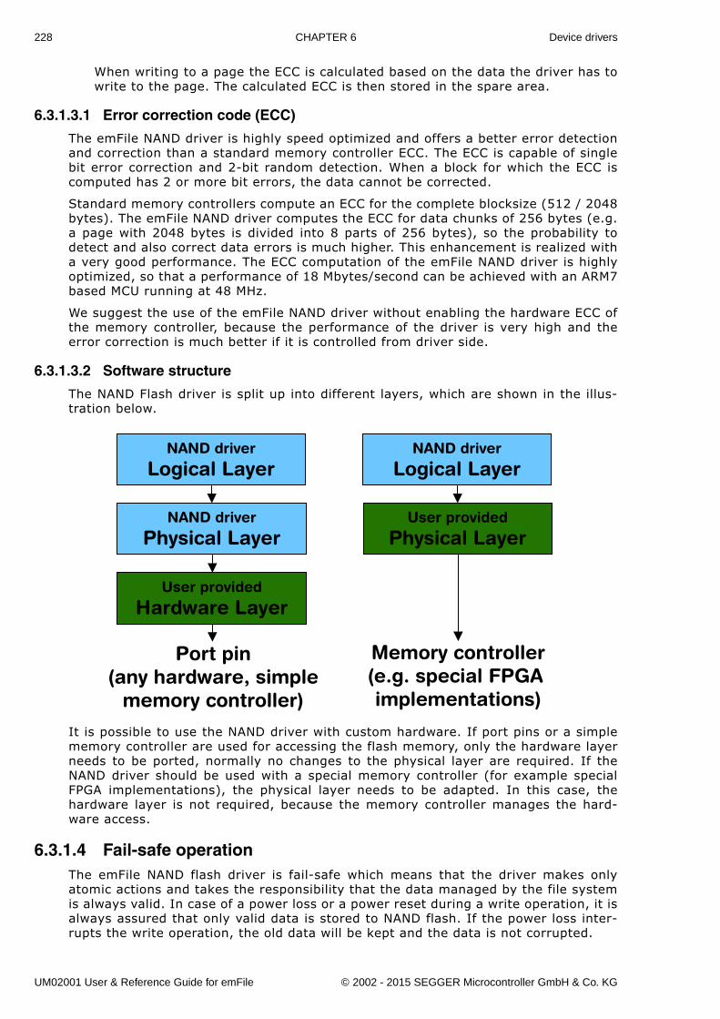
228 CHAPTER 6 Device drivers
When writing to a page the ECC is calculated based on the data the driver has towrite to the page. The calculated ECC is then stored in the spare area.
6.3.1.3.1 Error correction code (ECC)
The emFile NAND driver is highly speed optimized and offers a better error detectionand correction than a standard memory controller ECC. The ECC is capable of singlebit error correction and 2-bit random detection. When a block for which the ECC iscomputed has 2 or more bit errors, the data cannot be corrected.
Standard memory controllers compute an ECC for the complete blocksize (512 / 2048bytes). The emFile NAND driver computes the ECC for data chunks of 256 bytes (e.g.a page with 2048 bytes is divided into 8 parts of 256 bytes), so the probability todetect and also correct data errors is much higher. This enhancement is realized witha very good performance. The ECC computation of the emFile NAND driver is highlyoptimized, so that a performance of 18 Mbytes/second can be achieved with an ARM7based MCU running at 48 MHz.
We suggest the use of the emFile NAND driver without enabling the hardware ECC ofthe memory controller, because the performance of the driver is very high and theerror correction is much better if it is controlled from driver side.
6.3.1.3.2 Software structure
The NAND Flash driver is split up into different layers, which are shown in the illus-tration below.
It is possible to use the NAND driver with custom hardware. If port pins or a simplememory controller are used for accessing the flash memory, only the hardware layerneeds to be ported, normally no changes to the physical layer are required. If theNAND driver should be used with a special memory controller (for example specialFPGA implementations), the physical layer needs to be adapted. In this case, thehardware layer is not required, because the memory controller manages the hard-ware access.
6.3.1.4 Fail-safe operationThe emFile NAND flash driver is fail-safe which means that the driver makes onlyatomic actions and takes the responsibility that the data managed by the file systemis always valid. In case of a power loss or a power reset during a write operation, it isalways assured that only valid data is stored to NAND flash. If the power loss inter-rupts the write operation, the old data will be kept and the data is not corrupted.
NAND driver
Logical Layer
NAND driver
Physical Layer
User provided
Hardware Layer
NAND driver
Logical Layer
User provided
Physical Layer
Port pin(any hardware, simple
memory controller)
Memory controller(e.g. special FPGA implementations)
UM02001 User & Reference Guide for emFile © 2002 - 2015 SEGGER Microcontroller GmbH & Co. KG
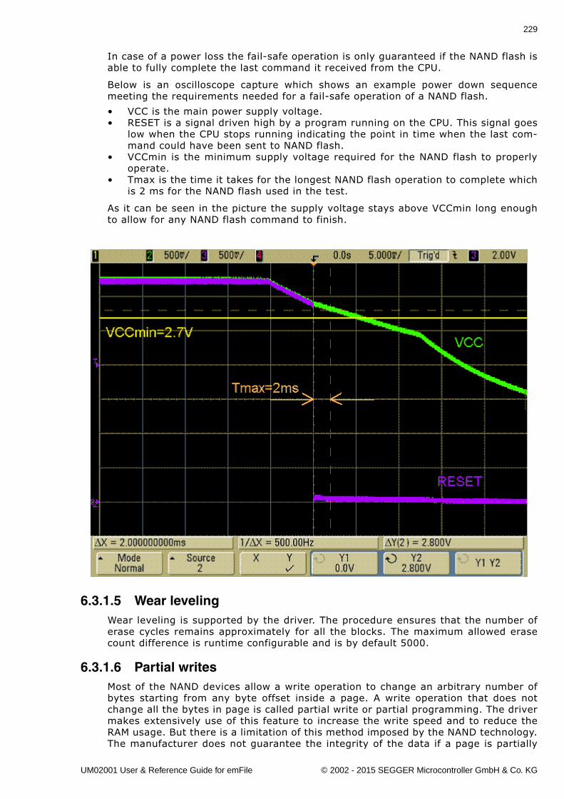
229
In case of a power loss the fail-safe operation is only guaranteed if the NAND flash isable to fully complete the last command it received from the CPU.
Below is an oscilloscope capture which shows an example power down sequencemeeting the requirements needed for a fail-safe operation of a NAND flash.
� VCC is the main power supply voltage.� RESET is a signal driven high by a program running on the CPU. This signal goes
low when the CPU stops running indicating the point in time when the last com-mand could have been sent to NAND flash.
� VCCmin is the minimum supply voltage required for the NAND flash to properlyoperate.
� Tmax is the time it takes for the longest NAND flash operation to complete whichis 2 ms for the NAND flash used in the test.
As it can be seen in the picture the supply voltage stays above VCCmin long enoughto allow for any NAND flash command to finish.
6.3.1.5 Wear levelingWear leveling is supported by the driver. The procedure ensures that the number oferase cycles remains approximately for all the blocks. The maximum allowed erasecount difference is runtime configurable and is by default 5000.
6.3.1.6 Partial writesMost of the NAND devices allow a write operation to change an arbitrary number ofbytes starting from any byte offset inside a page. A write operation that does notchange all the bytes in page is called partial write or partial programming. The drivermakes extensively use of this feature to increase the write speed and to reduce theRAM usage. But there is a limitation of this method imposed by the NAND technology.The manufacturer does not guarantee the integrity of the data if a page is partially
UM02001 User & Reference Guide for emFile © 2002 - 2015 SEGGER Microcontroller GmbH & Co. KG
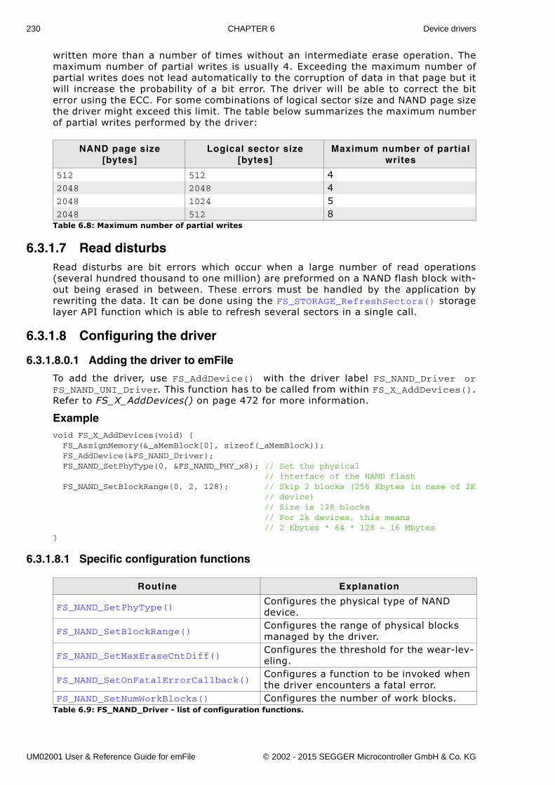
230 CHAPTER 6 Device drivers
written more than a number of times without an intermediate erase operation. Themaximum number of partial writes is usually 4. Exceeding the maximum number ofpartial writes does not lead automatically to the corruption of data in that page but itwill increase the probability of a bit error. The driver will be able to correct the biterror using the ECC. For some combinations of logical sector size and NAND page sizethe driver might exceed this limit. The table below summarizes the maximum numberof partial writes performed by the driver:
6.3.1.7 Read disturbsRead disturbs are bit errors which occur when a large number of read operations(several hundred thousand to one million) are preformed on a NAND flash block with-out being erased in between. These errors must be handled by the application byrewriting the data. It can be done using the FS_STORAGE_RefreshSectors() storagelayer API function which is able to refresh several sectors in a single call.
6.3.1.8 Configuring the driver
6.3.1.8.0.1 Adding the driver to emFile
To add the driver, use FS_AddDevice() with the driver label FS_NAND_Driver orFS_NAND_UNI_Driver. This function has to be called from within FS_X_AddDevices().Refer to FS_X_AddDevices() on page 472 for more information.
Examplevoid FS_X_AddDevices(void) { FS_AssignMemory(&_aMemBlock[0], sizeof(_aMemBlock)); FS_AddDevice(&FS_NAND_Driver); FS_NAND_SetPhyType(0, &FS_NAND_PHY_x8); // Set the physical // interface of the NAND flash FS_NAND_SetBlockRange(0, 2, 128); // Skip 2 blocks (256 Kbytes in case of 2K // device) // Size is 128 blocks // For 2k devices, this means // 2 Kbytes * 64 * 128 = 16 Mbytes}
6.3.1.8.1 Specific configuration functions
NAND page size[bytes]
Logical sector size[bytes]
Maximum number of partial writes
512 512 42048 2048 42048 1024 52048 512 8
Table 6.8: Maximum number of partial writes
Routine Explanation
FS_NAND_SetPhyType()Configures the physical type of NAND device.
FS_NAND_SetBlockRange()Configures the range of physical blocks managed by the driver.
FS_NAND_SetMaxEraseCntDiff()Configures the threshold for the wear-lev-eling.
FS_NAND_SetOnFatalErrorCallback()Configures a function to be invoked when the driver encounters a fatal error.
FS_NAND_SetNumWorkBlocks() Configures the number of work blocks.Table 6.9: FS_NAND_Driver - list of configuration functions.
UM02001 User & Reference Guide for emFile © 2002 - 2015 SEGGER Microcontroller GmbH & Co. KG
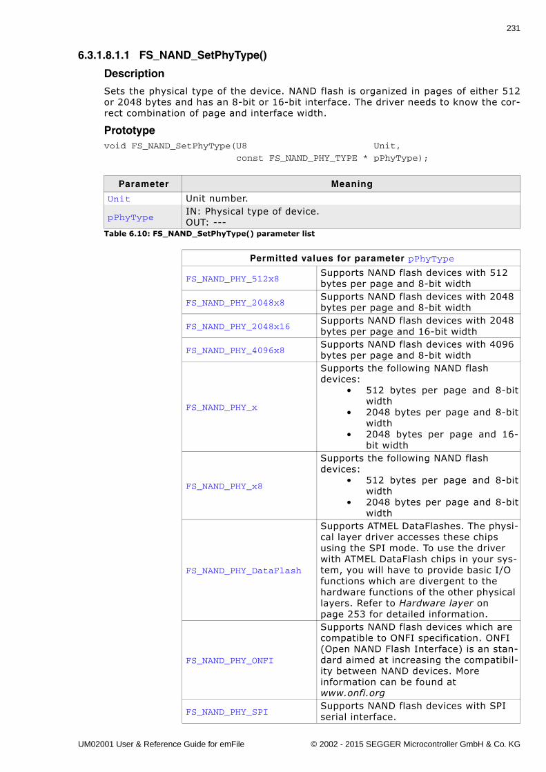
231
6.3.1.8.1.1 FS_NAND_SetPhyType()
Description
Sets the physical type of the device. NAND flash is organized in pages of either 512or 2048 bytes and has an 8-bit or 16-bit interface. The driver needs to know the cor-rect combination of page and interface width.
Prototypevoid FS_NAND_SetPhyType(U8 Unit,
const FS_NAND_PHY_TYPE * pPhyType);
Parameter Meaning
Unit Unit number.
pPhyTypeIN: Physical type of device.OUT: ---
Table 6.10: FS_NAND_SetPhyType() parameter list
Permitted values for parameter pPhyType
FS_NAND_PHY_512x8 Supports NAND flash devices with 512 bytes per page and 8-bit width
FS_NAND_PHY_2048x8Supports NAND flash devices with 2048 bytes per page and 8-bit width
FS_NAND_PHY_2048x16Supports NAND flash devices with 2048 bytes per page and 16-bit width
FS_NAND_PHY_4096x8Supports NAND flash devices with 4096 bytes per page and 8-bit width
FS_NAND_PHY_x
Supports the following NAND flash devices:
� 512 bytes per page and 8-bitwidth
� 2048 bytes per page and 8-bitwidth
� 2048 bytes per page and 16-bit width
FS_NAND_PHY_x8
Supports the following NAND flash devices:
� 512 bytes per page and 8-bitwidth
� 2048 bytes per page and 8-bitwidth
FS_NAND_PHY_DataFlash
Supports ATMEL DataFlashes. The physi-cal layer driver accesses these chips using the SPI mode. To use the driver with ATMEL DataFlash chips in your sys-tem, you will have to provide basic I/O functions which are divergent to the hardware functions of the other physical layers. Refer to Hardware layer on page 253 for detailed information.
FS_NAND_PHY_ONFI
Supports NAND flash devices which are compatible to ONFI specification. ONFI (Open NAND Flash Interface) is an stan-dard aimed at increasing the compatibil-ity between NAND devices. More information can be found at www.onfi.org
FS_NAND_PHY_SPISupports NAND flash devices with SPI serial interface.
UM02001 User & Reference Guide for emFile © 2002 - 2015 SEGGER Microcontroller GmbH & Co. KG
232 CHAPTER 6 Device drivers
Additional information
This function needs to be called for every NAND device added.
Example
Refer to Adding the driver to emFile on page 230 for an example.
UM02001 User & Reference Guide for emFile © 2002 - 2015 SEGGER Microcontroller GmbH & Co. KG
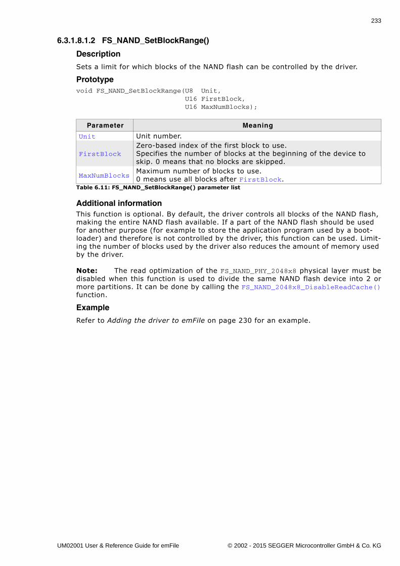
233
6.3.1.8.1.2 FS_NAND_SetBlockRange()
Description
Sets a limit for which blocks of the NAND flash can be controlled by the driver.
Prototypevoid FS_NAND_SetBlockRange(U8 Unit, U16 FirstBlock, U16 MaxNumBlocks);
Additional informationThis function is optional. By default, the driver controls all blocks of the NAND flash, making the entire NAND flash available. If a part of the NAND flash should be used for another purpose (for example to store the application program used by a boot-loader) and therefore is not controlled by the driver, this function can be used. Limit-ing the number of blocks used by the driver also reduces the amount of memory used by the driver.
Note: The read optimization of the FS_NAND_PHY_2048x8 physical layer must bedisabled when this function is used to divide the same NAND flash device into 2 ormore partitions. It can be done by calling the FS_NAND_2048x8_DisableReadCache()function.
Example
Refer to Adding the driver to emFile on page 230 for an example.
Parameter Meaning
Unit Unit number.
FirstBlockZero-based index of the first block to use. Specifies the number of blocks at the beginning of the device to skip. 0 means that no blocks are skipped.
MaxNumBlocksMaximum number of blocks to use.0 means use all blocks after FirstBlock.
Table 6.11: FS_NAND_SetBlockRange() parameter list
UM02001 User & Reference Guide for emFile © 2002 - 2015 SEGGER Microcontroller GmbH & Co. KG
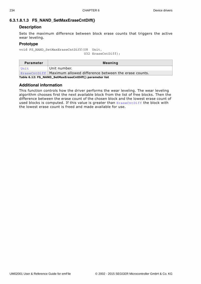
234 CHAPTER 6 Device drivers
6.3.1.8.1.3 FS_NAND_SetMaxEraseCntDiff()
Description
Sets the maximum difference between block erase counts that triggers the activewear leveling.
Prototypevoid FS_NAND_SetMaxEraseCntDiff(U8 Unit, U32 EraseCntDiff);
Additional informationThis function controls how the driver performs the wear leveling. The wear leveling algorithm chooses first the next available block from the list of free blocks. Then the difference between the erase count of the chosen block and the lowest erase count of used blocks is computed. If this value is greater than EraseCntDiff the block with the lowest erase count is freed and made available for use.
Parameter Meaning
Unit Unit number.EraseCntDiff Maximum allowed difference between the erase counts.
Table 6.12: FS_NAND_SetMaxEraseCntDiff() parameter list
UM02001 User & Reference Guide for emFile © 2002 - 2015 SEGGER Microcontroller GmbH & Co. KG
235
6.3.1.8.1.4 FS_NAND_SetOnFatalErrorCallback()
Description
Registers a function that should be invoked when a fatal error occurs.
Prototypevoid FS_NAND_SetOnFatalErrorCallback( FS_NAND_ON_FATAL_ERROR_CALLBACK * pfOnFatalError);
Additional information
The type of the callback function is defined as follows:
typedef int FS_NAND_ON_FATAL_ERROR_CALLBACK( FS_NAND_FATAL_ERROR_INFO * pFatalErrorInfo);
The parameter is a structure defined like this:
typedef struct { U8 Unit;} FS_NAND_FATAL_ERROR_INFO;
Unit is the number of NAND driver that encountered the fatal error.
If the callback function returns a 0 the driver marks the NAND flash as read-only. In this state all further write operations are rejected by the driver with an error. A low-level format is required to make the NAND flash writable. The callback function can also return a 1 in which case the medium is not marked as read-only.
Parameter Meaning
pfOnFatalError Pointer to callback function.Table 6.13: FS_NAND_SetOnFatalErrorCallback() parameter list
UM02001 User & Reference Guide for emFile © 2002 - 2015 SEGGER Microcontroller GmbH & Co. KG
236 CHAPTER 6 Device drivers
6.3.1.8.1.5 FS_NAND_SetNumWorkBlocks()
Description
Sets number of work blocks the driver uses for write operations.
Prototypevoid FS_NAND_SetNumWorkBlocks(U8 Unit, U32 NumWorkBlocks);
Additional informationWork blocks are physical blocks which the driver uses to temporarily store the data written to NAND flash. This function can be used to change the number of work blocks according to the requirements of an application. Usually, the write perfor-mance of the NAND driver improves when the number work blocks is increased. Please note that increasing the number of work blocks will also increase the RAM usage. By default, the NAND driver allocates 10% from the total number of blocks available but no more than 10 blocks. The minimum number of work blocks allocated by default depends whether journaling is used or not. If the journal is active the 4 work blocks are allocated else 3.
Parameter Meaning
Unit Unit number.NumWorkBlocks Number of work blocks.
Table 6.14: FS_NAND_SetNumWorkBlocks() parameter list
UM02001 User & Reference Guide for emFile © 2002 - 2015 SEGGER Microcontroller GmbH & Co. KG
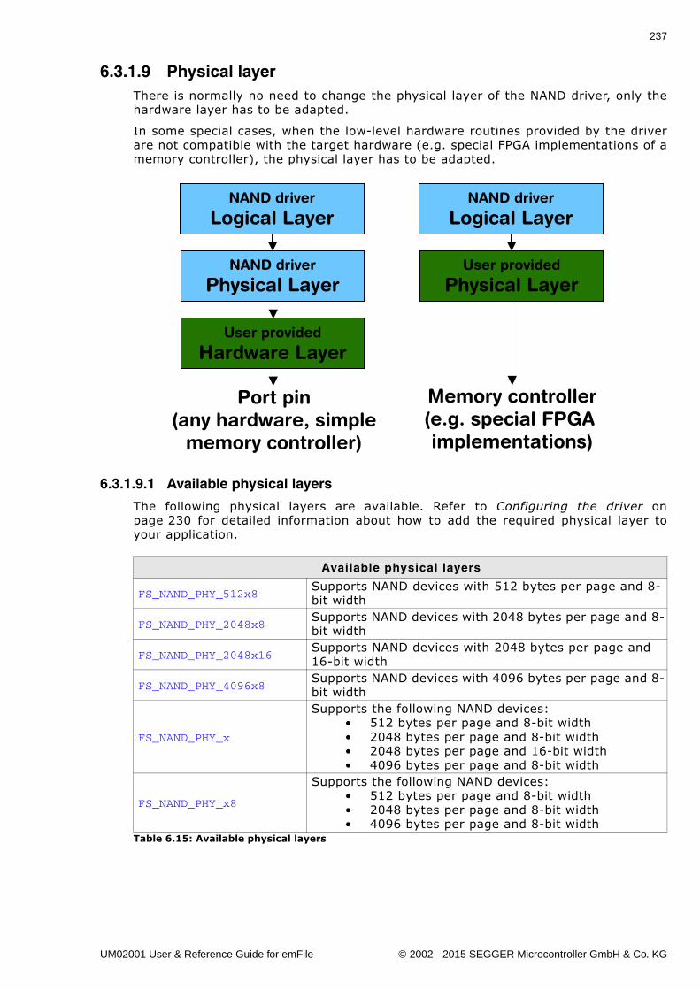
237
6.3.1.9 Physical layerThere is normally no need to change the physical layer of the NAND driver, only thehardware layer has to be adapted.
In some special cases, when the low-level hardware routines provided by the driverare not compatible with the target hardware (e.g. special FPGA implementations of amemory controller), the physical layer has to be adapted.
6.3.1.9.1 Available physical layers
The following physical layers are available. Refer to Configuring the driver onpage 230 for detailed information about how to add the required physical layer toyour application.
Available physical layers
FS_NAND_PHY_512x8Supports NAND devices with 512 bytes per page and 8-bit width
FS_NAND_PHY_2048x8Supports NAND devices with 2048 bytes per page and 8-bit width
FS_NAND_PHY_2048x16Supports NAND devices with 2048 bytes per page and 16-bit width
FS_NAND_PHY_4096x8Supports NAND devices with 4096 bytes per page and 8-bit width
FS_NAND_PHY_x
Supports the following NAND devices:� 512 bytes per page and 8-bit width� 2048 bytes per page and 8-bit width� 2048 bytes per page and 16-bit width� 4096 bytes per page and 8-bit width
FS_NAND_PHY_x8
Supports the following NAND devices:� 512 bytes per page and 8-bit width� 2048 bytes per page and 8-bit width� 4096 bytes per page and 8-bit width
Table 6.15: Available physical layers
NAND driver
Logical Layer
NAND driver
Physical Layer
User provided
Hardware Layer
NAND driver
Logical Layer
User provided
Physical Layer
Port pin(any hardware, simple
memory controller)
Memory controller(e.g. special FPGA implementations)
UM02001 User & Reference Guide for emFile © 2002 - 2015 SEGGER Microcontroller GmbH & Co. KG
238 CHAPTER 6 Device drivers
6.3.1.9.2 Physical layer functions
If there is a reason to change the physical layer anyhow, the functions which have tobe changed are organized in a function table. The function table is implemented in astructure of type FS_NAND_PHY_TYPE.
typedef struct FS_NAND_PHY_TYPE { int (*pfEraseBlock) (U8 Unit, U32 Block); int (*pfInitGetDeviceInfo) (U8 Unit, FS_NAND_DEVICE_INFO * pDevInfo); int (*pfIsWP) (U8 Unit); int (*pfRead) (U8 Unit, U32 PageNo, void * pData, unsigned Off, unsigned NumBytes); int (*pfReadEx) (U8 Unit, U32 PageNo, void * pData, unsigned Off, unsigned NumBytes, void * pSpare, unsigned OffSpare, unsigned NumBytesSpare); int (*pfWrite) (U8 Unit, U32 PageNo, const void * pData, unsigned Off, unsigned NumBytes); int (*pfWriteEx) (U8 Unit, U32 PageNo, const void * pData, unsigned Off, unsigned NumBytes, const void * pSpare, unsigned OffSpare, unsigned NumBytesSpare); int (*pfEnableECC) (U8 Unit); int (*pfDisableECC) (U8 Unit); int (*pfConfigureECC) (U8 Unit, U8 NumBitsCorrectable, U16 BytesPerECCBlock); int (*pfCopyPage) (U8 Unit, U32 PageNoSrc, U32 PageNoDest);} FS_NAND_PHY_TYPE;
FS_NAND_PHY_DataFlash
Supports ATMEL DataFlashes. The physical layer driver accesses these chips using the SPI mode. To use the driver with ATMEL DataFlash chips in your system, you will have to provide basic I/O functions which are diver-gent to the hardware functions of the other physical lay-ers. Refer to Hardware layer on page 253 for detailed information.
FS_NAND_PHY_ONFISupports NAND flash devices which are compatible to ONFI specification.
FS_NAND_PHY_SPI Supports NAND flash devices with SPI serial interface.
Available physical layers
Table 6.15: Available physical layers
UM02001 User & Reference Guide for emFile © 2002 - 2015 SEGGER Microcontroller GmbH & Co. KG
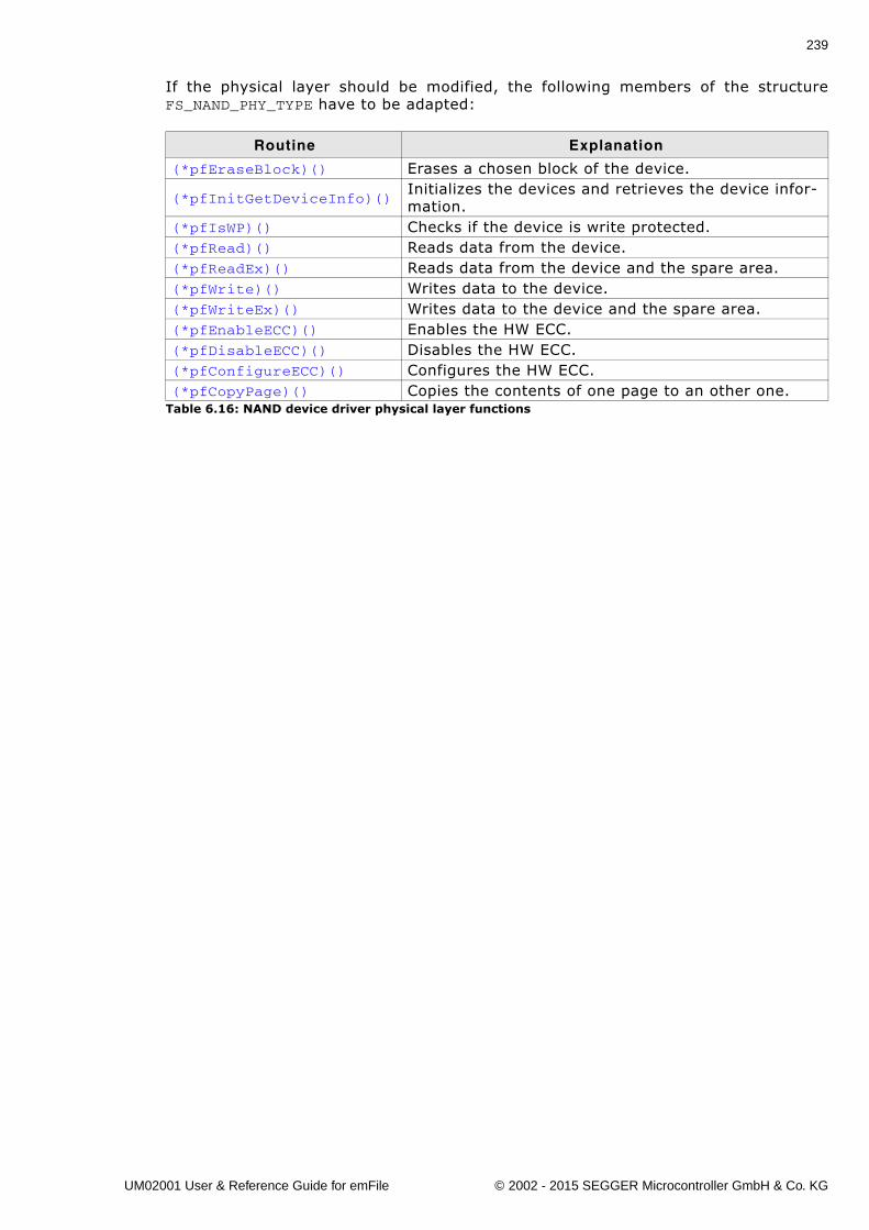
239
If the physical layer should be modified, the following members of the structureFS_NAND_PHY_TYPE have to be adapted:
Routine Explanation
(*pfEraseBlock)() Erases a chosen block of the device.
(*pfInitGetDeviceInfo)()Initializes the devices and retrieves the device infor-mation.
(*pfIsWP)() Checks if the device is write protected.(*pfRead)() Reads data from the device.(*pfReadEx)() Reads data from the device and the spare area.(*pfWrite)() Writes data to the device.(*pfWriteEx)() Writes data to the device and the spare area.(*pfEnableECC)() Enables the HW ECC.(*pfDisableECC)() Disables the HW ECC.(*pfConfigureECC)() Configures the HW ECC.(*pfCopyPage)() Copies the contents of one page to an other one.
Table 6.16: NAND device driver physical layer functions
UM02001 User & Reference Guide for emFile © 2002 - 2015 SEGGER Microcontroller GmbH & Co. KG
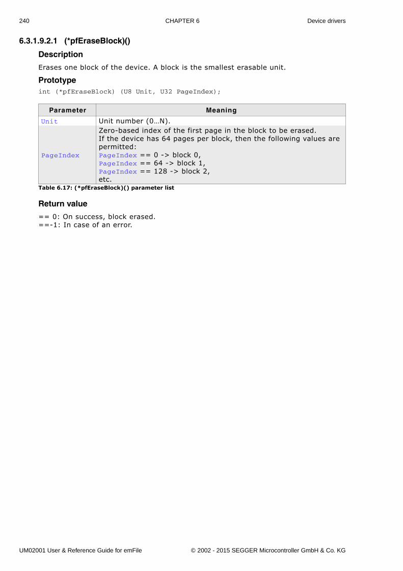
240 CHAPTER 6 Device drivers
6.3.1.9.2.1 (*pfEraseBlock)()
Description
Erases one block of the device. A block is the smallest erasable unit.
Prototypeint (*pfEraseBlock) (U8 Unit, U32 PageIndex);
Return value
== 0: On success, block erased.==-1: In case of an error.
Parameter Meaning
Unit Unit number (0�N).
PageIndex
Zero-based index of the first page in the block to be erased.If the device has 64 pages per block, then the following values are permitted:PageIndex == 0 -> block 0,PageIndex == 64 -> block 1,PageIndex == 128 -> block 2,etc.
Table 6.17: (*pfEraseBlock)() parameter list
UM02001 User & Reference Guide for emFile © 2002 - 2015 SEGGER Microcontroller GmbH & Co. KG
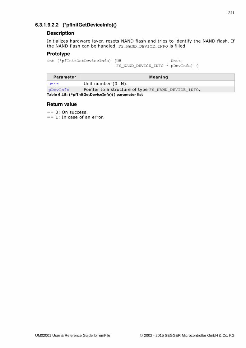
241
6.3.1.9.2.2 (*pfInitGetDeviceInfo)()
Description
Initializes hardware layer, resets NAND flash and tries to identify the NAND flash. Ifthe NAND flash can be handled, FS_NAND_DEVICE_INFO is filled.
Prototypeint (*pfInitGetDeviceInfo) (U8 Unit, FS_NAND_DEVICE_INFO * pDevInfo) {
Return value
== 0: On success.== 1: In case of an error.
Parameter Meaning
Unit Unit number (0�N).pDevInfo Pointer to a structure of type FS_NAND_DEVICE_INFO.
Table 6.18: (*pfInitGetDeviceInfo)() parameter list
UM02001 User & Reference Guide for emFile © 2002 - 2015 SEGGER Microcontroller GmbH & Co. KG
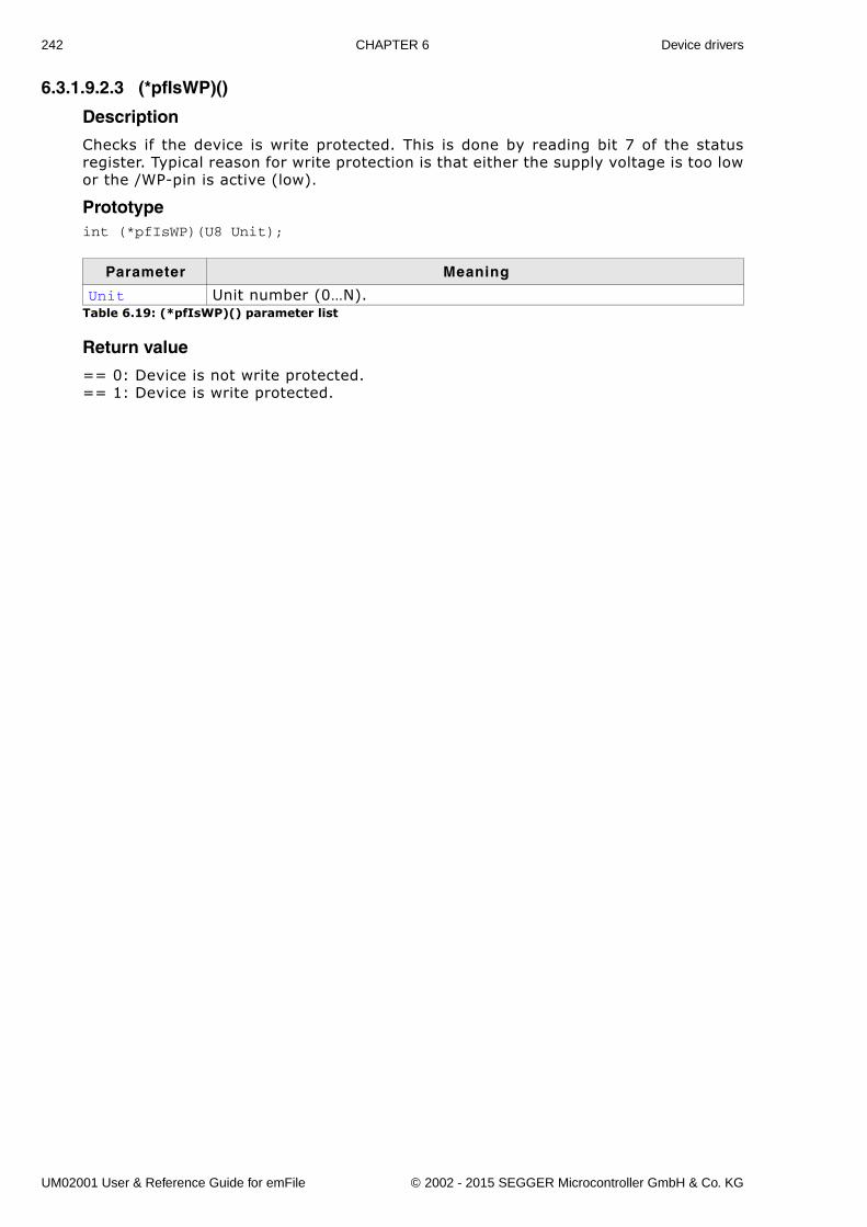
242 CHAPTER 6 Device drivers
6.3.1.9.2.3 (*pfIsWP)()
Description
Checks if the device is write protected. This is done by reading bit 7 of the statusregister. Typical reason for write protection is that either the supply voltage is too lowor the /WP-pin is active (low).
Prototypeint (*pfIsWP)(U8 Unit);
Return value
== 0: Device is not write protected.== 1: Device is write protected.
Parameter Meaning
Unit Unit number (0�N).Table 6.19: (*pfIsWP)() parameter list
UM02001 User & Reference Guide for emFile © 2002 - 2015 SEGGER Microcontroller GmbH & Co. KG
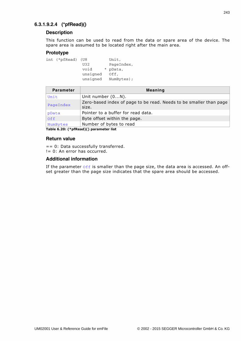
243
6.3.1.9.2.4 (*pfRead)()
Description
This function can be used to read from the data or spare area of the device. Thespare area is assumed to be located right after the main area.
Prototypeint (*pfRead) (U8 Unit, U32 PageIndex, void * pData, unsigned Off, unsigned NumBytes);
Return value
== 0: Data successfully transferred.!= 0: An error has occurred.
Additional information
If the parameter Off is smaller than the page size, the data area is accessed. An off-set greater than the page size indicates that the spare area should be accessed.
Parameter Meaning
Unit Unit number (0...N).
PageIndexZero-based index of page to be read. Needs to be smaller than page size.
pData Pointer to a buffer for read data.Off Byte offset within the page.NumBytes Number of bytes to read
Table 6.20: (*pfRead)() parameter list
UM02001 User & Reference Guide for emFile © 2002 - 2015 SEGGER Microcontroller GmbH & Co. KG
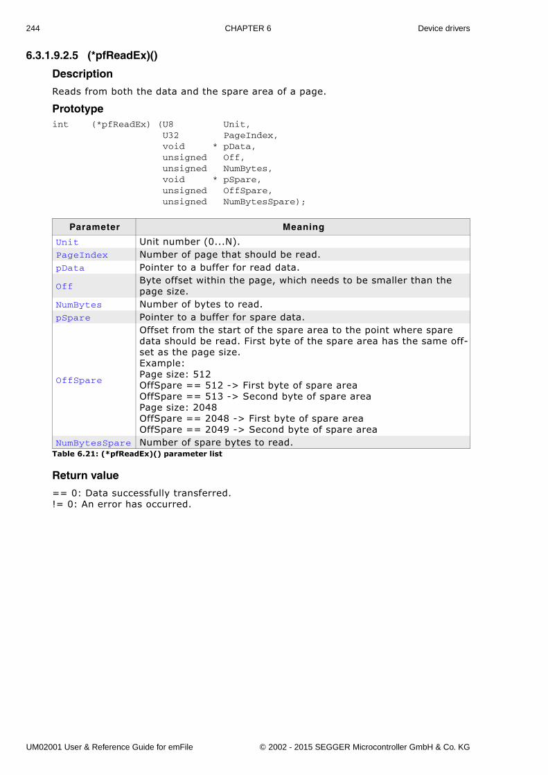
244 CHAPTER 6 Device drivers
6.3.1.9.2.5 (*pfReadEx)()
Description
Reads from both the data and the spare area of a page.
Prototypeint (*pfReadEx) (U8 Unit, U32 PageIndex, void * pData, unsigned Off, unsigned NumBytes, void * pSpare, unsigned OffSpare, unsigned NumBytesSpare);
Return value
== 0: Data successfully transferred.!= 0: An error has occurred.
Parameter Meaning
Unit Unit number (0...N).PageIndex Number of page that should be read. pData Pointer to a buffer for read data.
OffByte offset within the page, which needs to be smaller than the page size.
NumBytes Number of bytes to read.pSpare Pointer to a buffer for spare data.
OffSpare
Offset from the start of the spare area to the point where spare data should be read. First byte of the spare area has the same off-set as the page size.Example:Page size: 512OffSpare == 512 -> First byte of spare areaOffSpare == 513 -> Second byte of spare areaPage size: 2048OffSpare == 2048 -> First byte of spare areaOffSpare == 2049 -> Second byte of spare area
NumBytesSpare Number of spare bytes to read.Table 6.21: (*pfReadEx)() parameter list
UM02001 User & Reference Guide for emFile © 2002 - 2015 SEGGER Microcontroller GmbH & Co. KG
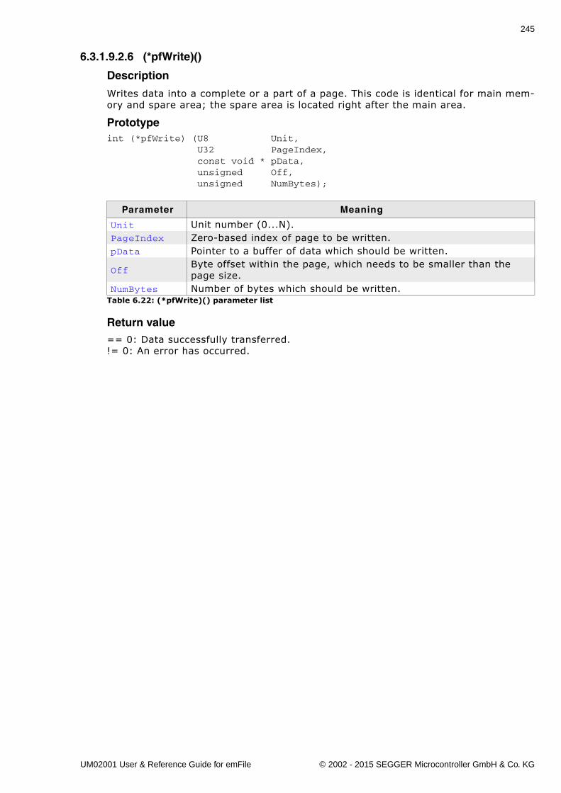
245
6.3.1.9.2.6 (*pfWrite)()
Description
Writes data into a complete or a part of a page. This code is identical for main mem-ory and spare area; the spare area is located right after the main area.
Prototypeint (*pfWrite) (U8 Unit, U32 PageIndex, const void * pData, unsigned Off, unsigned NumBytes);
Return value== 0: Data successfully transferred.!= 0: An error has occurred.
Parameter Meaning
Unit Unit number (0...N).PageIndex Zero-based index of page to be written.pData Pointer to a buffer of data which should be written.
OffByte offset within the page, which needs to be smaller than the page size.
NumBytes Number of bytes which should be written.Table 6.22: (*pfWrite)() parameter list
UM02001 User & Reference Guide for emFile © 2002 - 2015 SEGGER Microcontroller GmbH & Co. KG
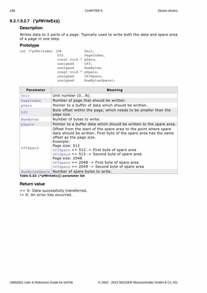
246 CHAPTER 6 Device drivers
6.3.1.9.2.7 (*pfWriteEx)()
Description
Writes data to 2 parts of a page. Typically used to write both the data and spare areaof a page in one step.
Prototypeint (*pfWriteEx) (U8 Unit, U32 PageIndex, const void * pData, unsigned Off, unsigned NumBytes, const void * pSpare, unsigned OffSpare, unsigned NumBytesSpare);
Return value
== 0: Data successfully transferred.!= 0: An error has occurred.
Parameter Meaning
Unit Unit number (0...N).PageIndex Number of page that should be written. pData Pointer to a buffer of data which should be written.
OffByte offset within the page, which needs to be smaller than the page size.
NumBytes Number of bytes to write.pSpare Pointer to a buffer data which should be written to the spare area.
OffSpare
Offset from the start of the spare area to the point where spare data should be written. First byte of the spare area has the same offset as the page size.Example:Page size: 512OffSpare == 512 -> First byte of spare areaOffSpare == 513 -> Second byte of spare areaPage size: 2048OffSpare == 2048 -> First byte of spare areaOffSpare == 2049 -> Second byte of spare area
NumBytesSpare Number of spare bytes to write.Table 6.23: (*pfWriteEx)() parameter list
UM02001 User & Reference Guide for emFile © 2002 - 2015 SEGGER Microcontroller GmbH & Co. KG
247
6.3.1.9.2.8 (*pfEnableECC)()
Description
This function activates the HW ECC.
Prototypeint (*pfEnableECC)(U8 Unit);
Return value
==0: HW ECC enabled.!= 0: An error has occurred.
Additional information
With the HW ECC enabled the (*pfRead)() and (*pfReadEx)() functions will returncorrected data. The function is called only by the Universal NAND driver.
Parameter Meaning
Unit Unit number (0...N).Table 6.24: (*pfEnableECC)() parameter list
UM02001 User & Reference Guide for emFile © 2002 - 2015 SEGGER Microcontroller GmbH & Co. KG
248 CHAPTER 6 Device drivers
6.3.1.9.2.9 (*pfDisableECC)()
Description
This function deactivates the HW ECC.
Prototypeint (*pfDisableECC)(U8 Unit);
Return value
==0: HW ECC disabled.!= 0: An error has occurred.
Additional information
With the HW ECC disabled the (*pfRead)() and (*pfReadEx)() functions will returnuncorrected data. The function is called only by the Universal NAND driver.
Parameter Meaning
Unit Unit number (0...N).Table 6.25: (*pfDisableECC)() parameter list
UM02001 User & Reference Guide for emFile © 2002 - 2015 SEGGER Microcontroller GmbH & Co. KG
249
6.3.1.9.2.10 (*pfConfigureECC)()
Description
This function configures the HW ECC.
Prototypeint (*pfConfigureECC)(U8 Unit, U8 NumBitsCorrectable, U16 BytesPerECCBlock);
Return value
==0: HW ECC configured.!= 0: An error has occurred.
Additional information
This function is optional and is called only by the Universal NAND driver. It must beimplemented only when the NAND flash device is interfaced to a NAND flash control-ler with HW ECC. The NAND flash controller should be configured to correct Num-BitsCorrectable bit errors over BytesPerECCBlock bytes of data and spare area.
Parameter Meaning
Unit Unit number (0...N).NumBitsCorrectable Number of error bits the HW ECC should correct.BytesPerECCBlock The ECC is computed over this number of bytes.
Table 6.26: (*pfConfigureECC)() parameter list
UM02001 User & Reference Guide for emFile © 2002 - 2015 SEGGER Microcontroller GmbH & Co. KG
250 CHAPTER 6 Device drivers
6.3.1.9.2.11 (*pfCopyPage)()
Description
Copies the contents of an entire NAND page (including the spare area) to an otherpage.
Prototypeint (*pfCopyPage)(U8 Unit, U32 PageNoSrc, U32 PageNoDest);
Return value
==0: Page copied.!= 0: An error occurred.
Additional information
This function is optional and is called only by the Universal NAND driver. It has to beimplemented only when the NAND flash device supports HW ECC. The page should becopied by reading the source page to internal register of NAND flash device followedby a write to destination page.
Parameter Meaning
Unit Unit number (0...N).PageNoSrc Index of the source page.PageNoDest Index of the destination page.
Table 6.27: (*pfCopyPage)() parameter list
UM02001 User & Reference Guide for emFile © 2002 - 2015 SEGGER Microcontroller GmbH & Co. KG
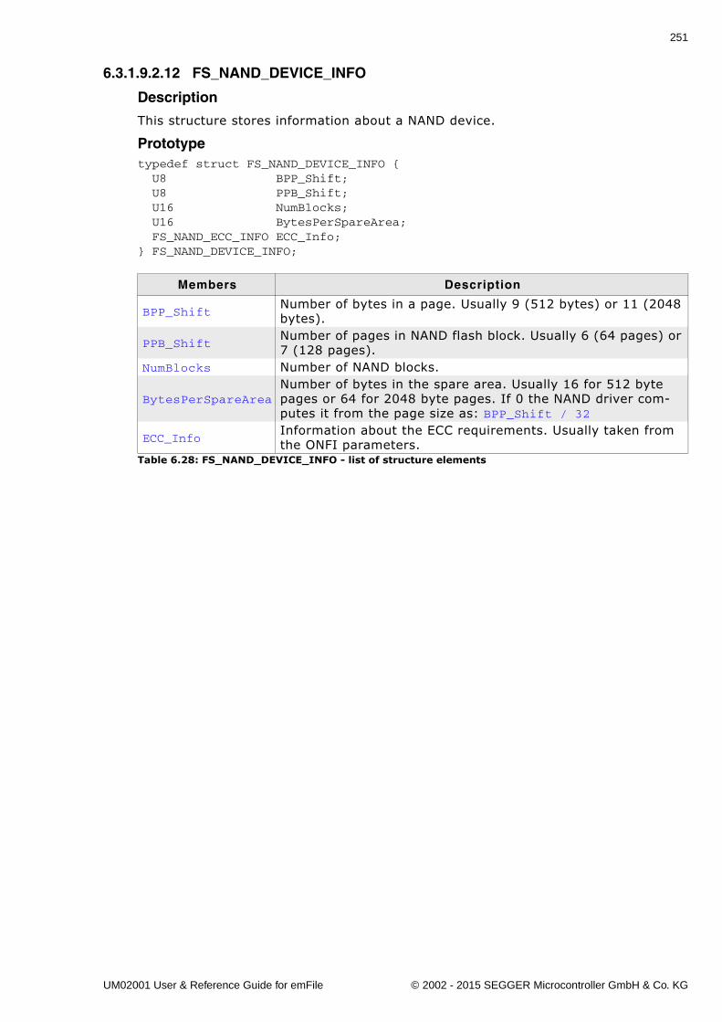
251
6.3.1.9.2.12 FS_NAND_DEVICE_INFO
Description
This structure stores information about a NAND device.
Prototypetypedef struct FS_NAND_DEVICE_INFO { U8 BPP_Shift; U8 PPB_Shift; U16 NumBlocks; U16 BytesPerSpareArea; FS_NAND_ECC_INFO ECC_Info;} FS_NAND_DEVICE_INFO;
Members Description
BPP_ShiftNumber of bytes in a page. Usually 9 (512 bytes) or 11 (2048 bytes).
PPB_ShiftNumber of pages in NAND flash block. Usually 6 (64 pages) or 7 (128 pages).
NumBlocks Number of NAND blocks.
BytesPerSpareAreaNumber of bytes in the spare area. Usually 16 for 512 byte pages or 64 for 2048 byte pages. If 0 the NAND driver com-putes it from the page size as: BPP_Shift / 32
ECC_InfoInformation about the ECC requirements. Usually taken from the ONFI parameters.
Table 6.28: FS_NAND_DEVICE_INFO - list of structure elements
UM02001 User & Reference Guide for emFile © 2002 - 2015 SEGGER Microcontroller GmbH & Co. KG
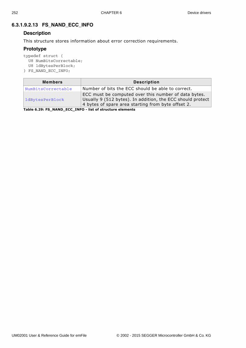
252 CHAPTER 6 Device drivers
6.3.1.9.2.13 FS_NAND_ECC_INFO
Description
This structure stores information about error correction requirements.
Prototypetypedef struct { U8 NumBitsCorrectable; U8 ldBytesPerBlock;} FS_NAND_ECC_INFO;
Members Description
NumBitsCorrectable Number of bits the ECC should be able to correct.
ldBytesPerBlockECC must be computed over this number of data bytes. Usually 9 (512 bytes). In addition, the ECC should protect 4 bytes of spare area starting from byte offset 2.
Table 6.29: FS_NAND_ECC_INFO - list of structure elements
UM02001 User & Reference Guide for emFile © 2002 - 2015 SEGGER Microcontroller GmbH & Co. KG
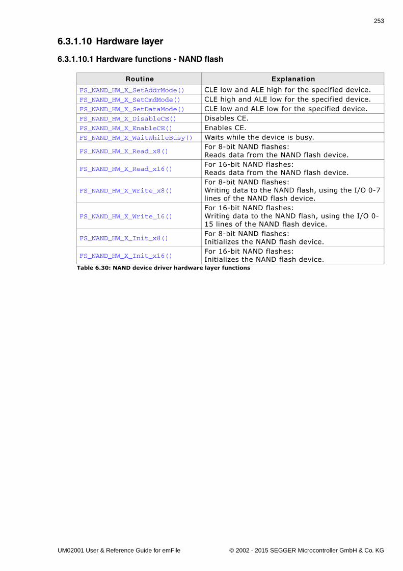
253
6.3.1.10 Hardware layer
6.3.1.10.1 Hardware functions - NAND flash
Routine Explanation
FS_NAND_HW_X_SetAddrMode() CLE low and ALE high for the specified device.FS_NAND_HW_X_SetCmdMode() CLE high and ALE low for the specified device.FS_NAND_HW_X_SetDataMode() CLE low and ALE low for the specified device.FS_NAND_HW_X_DisableCE() Disables CE.FS_NAND_HW_X_EnableCE() Enables CE.FS_NAND_HW_X_WaitWhileBusy() Waits while the device is busy.
FS_NAND_HW_X_Read_x8()For 8-bit NAND flashes:Reads data from the NAND flash device.
FS_NAND_HW_X_Read_x16()For 16-bit NAND flashes:Reads data from the NAND flash device.
FS_NAND_HW_X_Write_x8()For 8-bit NAND flashes:Writing data to the NAND flash, using the I/O 0-7 lines of the NAND flash device.
FS_NAND_HW_X_Write_16()For 16-bit NAND flashes:Writing data to the NAND flash, using the I/O 0-15 lines of the NAND flash device.
FS_NAND_HW_X_Init_x8()For 8-bit NAND flashes:Initializes the NAND flash device.
FS_NAND_HW_X_Init_x16()For 16-bit NAND flashes:Initializes the NAND flash device.
Table 6.30: NAND device driver hardware layer functions
UM02001 User & Reference Guide for emFile © 2002 - 2015 SEGGER Microcontroller GmbH & Co. KG
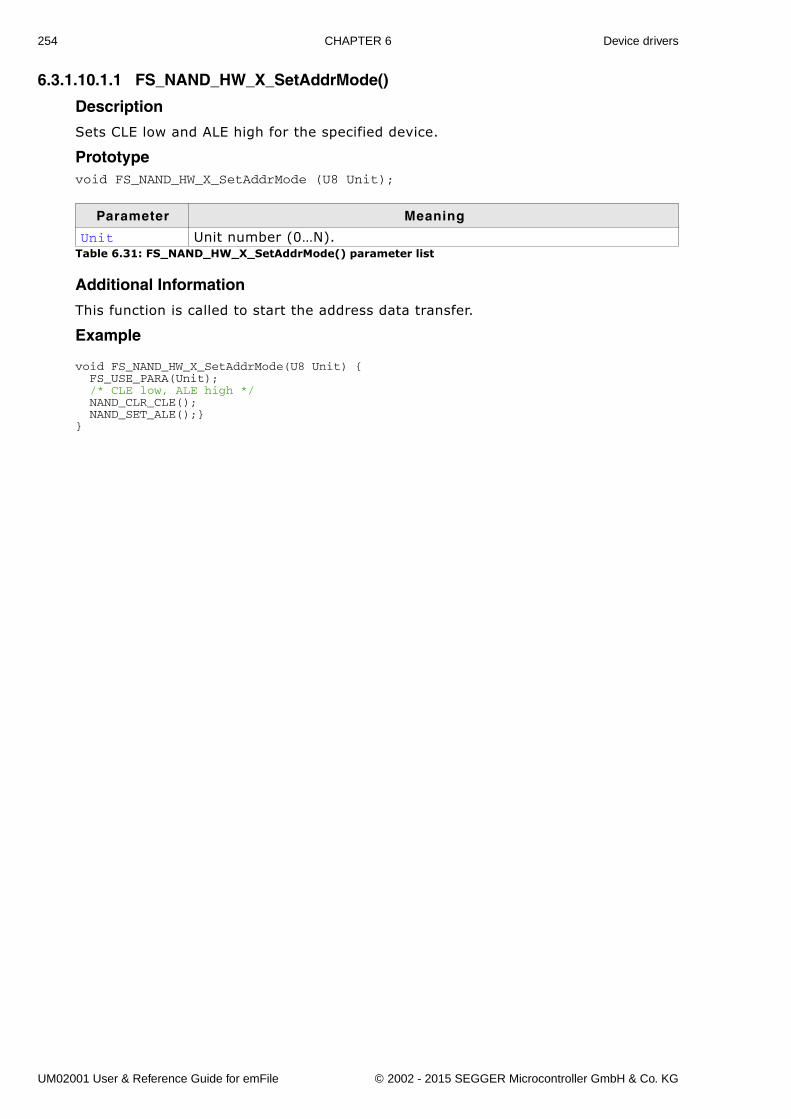
254 CHAPTER 6 Device drivers
6.3.1.10.1.1 FS_NAND_HW_X_SetAddrMode()
Description
Sets CLE low and ALE high for the specified device.
Prototypevoid FS_NAND_HW_X_SetAddrMode (U8 Unit);
Additional Information
This function is called to start the address data transfer.
Example
void FS_NAND_HW_X_SetAddrMode(U8 Unit) { FS_USE_PARA(Unit); /* CLE low, ALE high */ NAND_CLR_CLE(); NAND_SET_ALE();}}
Parameter Meaning
Unit Unit number (0�N).Table 6.31: FS_NAND_HW_X_SetAddrMode() parameter list
UM02001 User & Reference Guide for emFile © 2002 - 2015 SEGGER Microcontroller GmbH & Co. KG
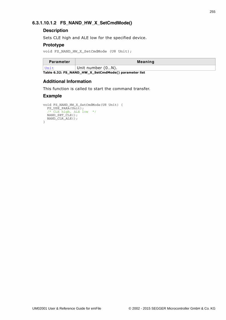
255
6.3.1.10.1.2 FS_NAND_HW_X_SetCmdMode()
Description
Sets CLE high and ALE low for the specified device.
Prototypevoid FS_NAND_HW_X_SetCmdMode (U8 Unit);
Additional Information
This function is called to start the command transfer.
Example
void FS_NAND_HW_X_SetCmdMode(U8 Unit) { FS_USE_PARA(Unit); /* CLE high, ALE low */ NAND_SET_CLE(); NAND_CLR_ALE();}
Parameter Meaning
Unit Unit number (0�N).Table 6.32: FS_NAND_HW_X_SetCmdMode() parameter list
UM02001 User & Reference Guide for emFile © 2002 - 2015 SEGGER Microcontroller GmbH & Co. KG
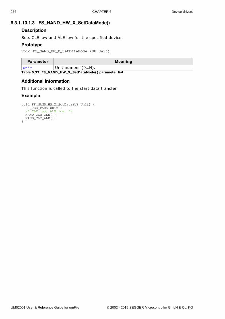
256 CHAPTER 6 Device drivers
6.3.1.10.1.3 FS_NAND_HW_X_SetDataMode()
Description
Sets CLE low and ALE low for the specified device.
Prototypevoid FS_NAND_HW_X_SetDataMode (U8 Unit);
Additional Information
This function is called to the start data transfer.
Example
void FS_NAND_HW_X_SetData(U8 Unit) { FS_USE_PARA(Unit); /* CLE low, ALE low */ NAND_CLR_CLE(); NAND_CLR_ALE();}
Parameter Meaning
Unit Unit number (0�N).Table 6.33: FS_NAND_HW_X_SetDataMode() parameter list
UM02001 User & Reference Guide for emFile © 2002 - 2015 SEGGER Microcontroller GmbH & Co. KG
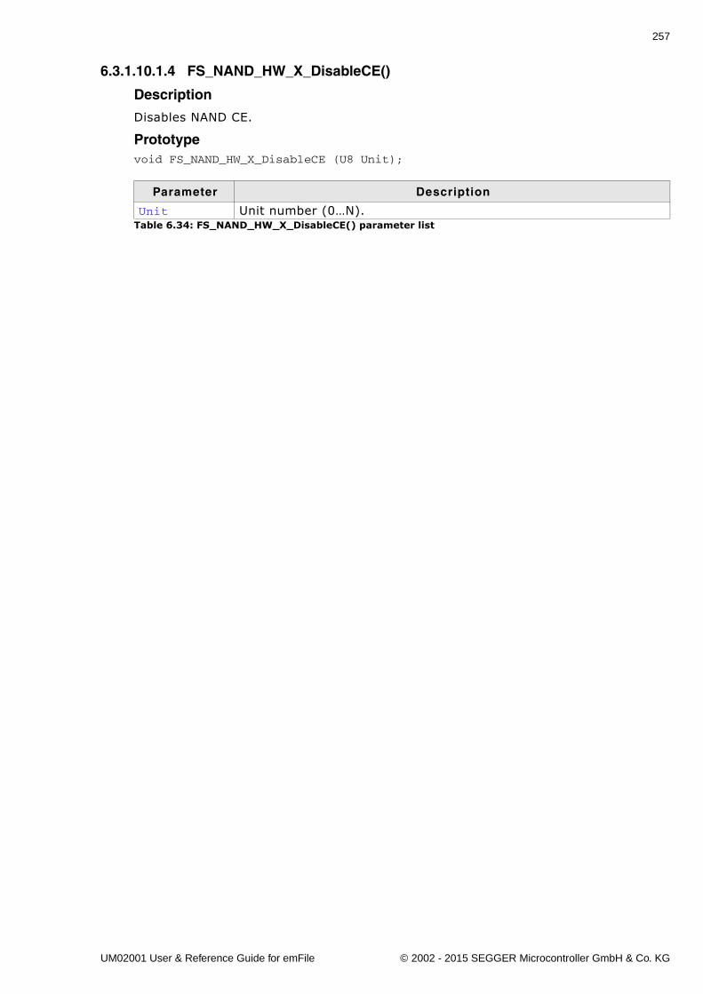
257
6.3.1.10.1.4 FS_NAND_HW_X_DisableCE()
Description
Disables NAND CE.
Prototypevoid FS_NAND_HW_X_DisableCE (U8 Unit);
Parameter Description
Unit Unit number (0�N).Table 6.34: FS_NAND_HW_X_DisableCE() parameter list
UM02001 User & Reference Guide for emFile © 2002 - 2015 SEGGER Microcontroller GmbH & Co. KG
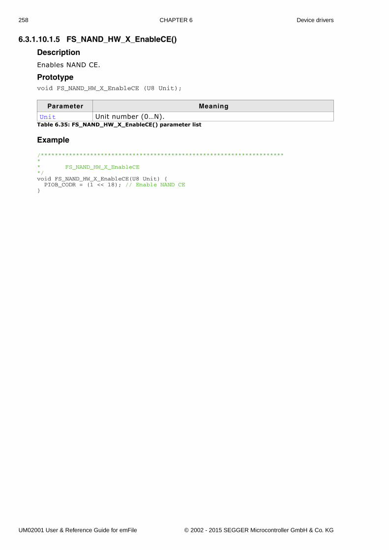
258 CHAPTER 6 Device drivers
6.3.1.10.1.5 FS_NAND_HW_X_EnableCE()
Description
Enables NAND CE.
Prototypevoid FS_NAND_HW_X_EnableCE (U8 Unit);
Example
/*********************************************************************** FS_NAND_HW_X_EnableCE*/void FS_NAND_HW_X_EnableCE(U8 Unit) { PIOB_CODR = (1 << 18); // Enable NAND CE}
Parameter Meaning
Unit Unit number (0�N).Table 6.35: FS_NAND_HW_X_EnableCE() parameter list
UM02001 User & Reference Guide for emFile © 2002 - 2015 SEGGER Microcontroller GmbH & Co. KG
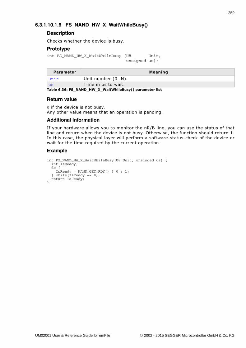
259
6.3.1.10.1.6 FS_NAND_HW_X_WaitWhileBusy()
Description
Checks whether the device is busy.
Prototypeint FS_NAND_HW_X_WaitWhileBusy (U8 Unit, unsigned us);
Return value
0 if the device is not busy.Any other value means that an operation is pending.
Additional Information
If your hardware allows you to monitor the nR/B line, you can use the status of thatline and return when the device is not busy. Otherwise, the function should return 1.In this case, the physical layer will perform a software-status-check of the device orwait for the time required by the current operation.
Example
int FS_NAND_HW_X_WaitWhileBusy(U8 Unit, unsinged us) { int IsReady; do { IsReady = NAND_GET_RDY() ? 0 : 1; } while(IsReady == 0); return IsReady;}
Parameter Meaning
Unit Unit number (0�N).us Time in µs to wait.
Table 6.36: FS_NAND_HW_X_WaitWhileBusy() parameter list
UM02001 User & Reference Guide for emFile © 2002 - 2015 SEGGER Microcontroller GmbH & Co. KG
260 CHAPTER 6 Device drivers
6.3.1.10.1.7 FS_NAND_HW_X_Read_x8()
Description
Reads data from an 8-bit NAND flash device, using the I/O 0-7 lines.
Prototypevoid FS_NAND_HW_X_Read_x8 (U8 Unit, U8 * pBuffer, unsigned NumBytes);
Additional Information
When reading from the device, usually you will not have to take care of handling theRE line because that is done automatically by the hardware.If you do have to control the RE line, make sure that timing is according to yourNAND flash device specification.
Example
void FS_NAND_HW_X_Read_x8(U8 Unit, U8 * pBuffer, unsigned NumBytes) { SET_DATA2INPUT(); do { NAND_CLR_RE(); /* RE is active low */ NAND_GET_DATA(*pBuffer); pBuffer++; NAND_SET_RE(); /* disable RE */ } while (--NumBytes);}
Parameter Meaning
Unit Unit number (0�N).pBuffer Pointer to a buffer to store the read data.NumBytes Number of bytes that should be stored into the buffer.
Table 6.37: FS_NAND_HW_X_Read_x8() parameter list
UM02001 User & Reference Guide for emFile © 2002 - 2015 SEGGER Microcontroller GmbH & Co. KG
261
6.3.1.10.1.8 FS_NAND_HW_X_Read_x16()
Description
Reads data from a 16-bit NAND flash device, using the I/O 0-15 lines.
Prototypevoid FS_NAND_HW_X_Read_x16 (U8 Unit, U8 * pBuffer, unsigned NumBytes);
Additional Information
When reading from the device, usually you will not have to take care of handling theRE line because that is done automatically by the hardware.If you do have to control the RE line, make sure that timing is according to yourNAND flash device specification.
Parameter Meaning
Unit Unit number (0�N).pBuffer Pointer to a buffer to store the read data.NumBytes Number of bytes that should be stored into the buffer.
Table 6.38: FS_NAND_HW_X_Read_x16() parameter list
UM02001 User & Reference Guide for emFile © 2002 - 2015 SEGGER Microcontroller GmbH & Co. KG
262 CHAPTER 6 Device drivers
6.3.1.10.1.9 FS_NAND_HW_X_Write_x8()
Description
Writes data to an 8-bit NAND flash, using the I/O 0-7 lines of the NAND flash device.
Prototypevoid FS_NAND_HW_X_Write_x8 (U8 Unit, const U8 * pBuffer, unsigned NumBytes);;
Additional Information
When writing data to the device, usually you will not have to take care of handlingthe WE line because that is done automatically by the hardware.If you do have to control the WE line, make sure that timing is according to yourNAND flash device specifications.
Example
void FS_NAND_HW_X_Write_x8(U8 Unit, U8 * pBuffer, unsigned NumBytes) { SET_DATA2OUTPUT(); do { NAND_CLR_WE(); /* WE is active low */ NAND_SET_DATA(*pBuffer); pBuffer++; NAND_SET_WE(); /* disable WE */ } while (--NumBytes); }
Parameter Meaning
Unit Unit number (0�N).pBuffer Pointer to a buffer of data which should be written.NumBytes Number of bytes that should be transferred to the NAND flash.
Table 6.39: FS_NAND_HW_X_Write_x8() parameter list
UM02001 User & Reference Guide for emFile © 2002 - 2015 SEGGER Microcontroller GmbH & Co. KG
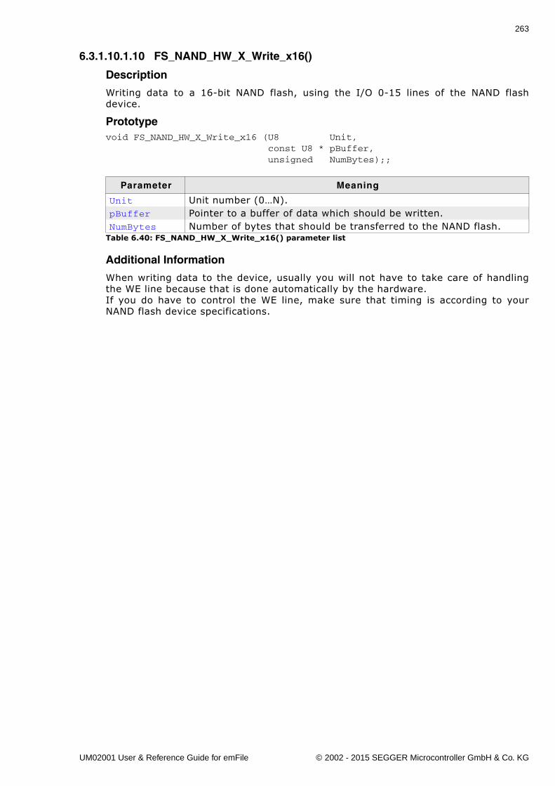
263
6.3.1.10.1.10 FS_NAND_HW_X_Write_x16()
Description
Writing data to a 16-bit NAND flash, using the I/O 0-15 lines of the NAND flashdevice.
Prototypevoid FS_NAND_HW_X_Write_x16 (U8 Unit, const U8 * pBuffer, unsigned NumBytes);;
Additional Information
When writing data to the device, usually you will not have to take care of handlingthe WE line because that is done automatically by the hardware.If you do have to control the WE line, make sure that timing is according to yourNAND flash device specifications.
Parameter Meaning
Unit Unit number (0�N).pBuffer Pointer to a buffer of data which should be written.NumBytes Number of bytes that should be transferred to the NAND flash.
Table 6.40: FS_NAND_HW_X_Write_x16() parameter list
UM02001 User & Reference Guide for emFile © 2002 - 2015 SEGGER Microcontroller GmbH & Co. KG
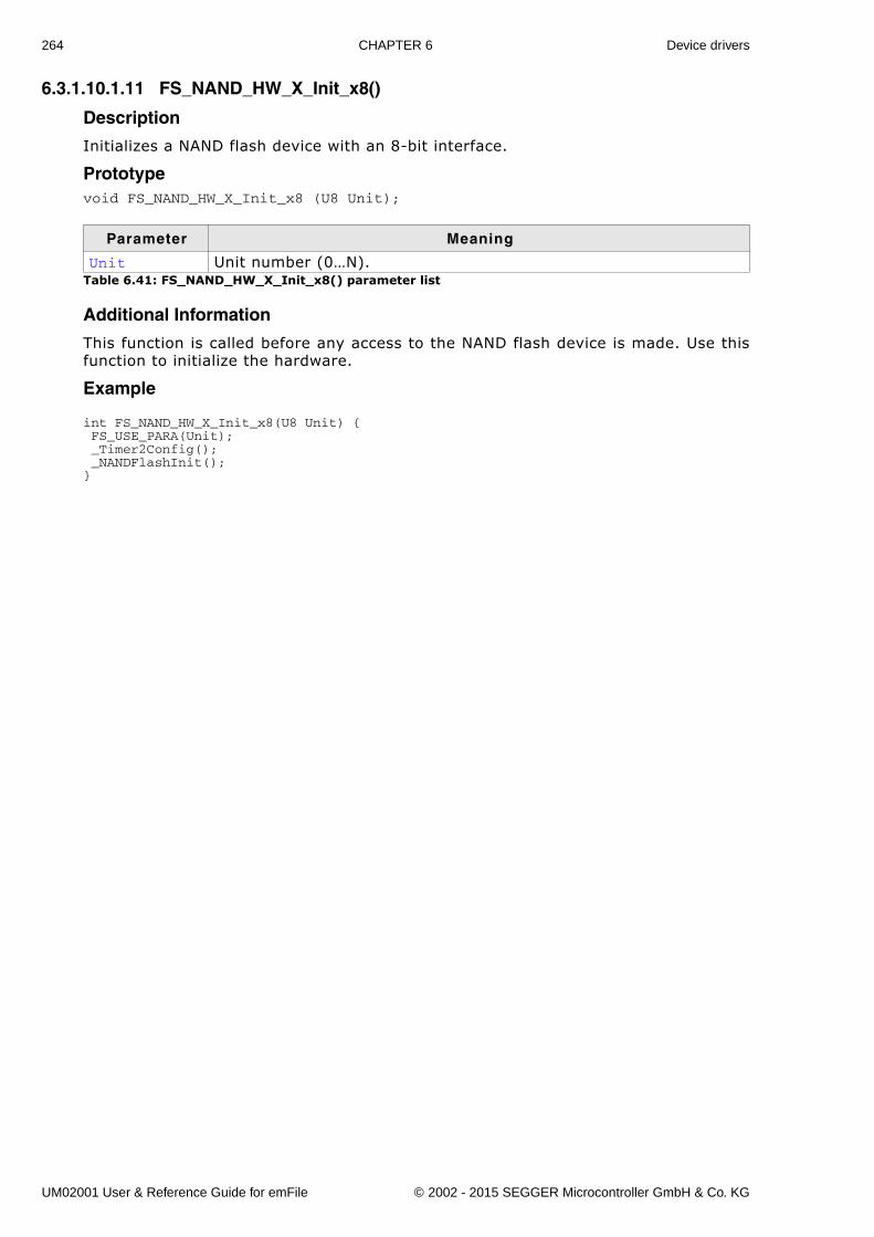
264 CHAPTER 6 Device drivers
6.3.1.10.1.11 FS_NAND_HW_X_Init_x8()
Description
Initializes a NAND flash device with an 8-bit interface.
Prototypevoid FS_NAND_HW_X_Init_x8 (U8 Unit);
Additional Information
This function is called before any access to the NAND flash device is made. Use thisfunction to initialize the hardware.
Example
int FS_NAND_HW_X_Init_x8(U8 Unit) { FS_USE_PARA(Unit); _Timer2Config(); _NANDFlashInit();}
Parameter Meaning
Unit Unit number (0�N).Table 6.41: FS_NAND_HW_X_Init_x8() parameter list
UM02001 User & Reference Guide for emFile © 2002 - 2015 SEGGER Microcontroller GmbH & Co. KG
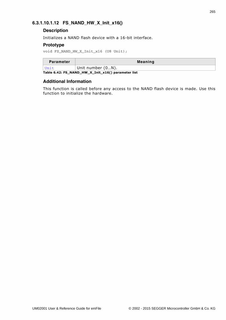
265
6.3.1.10.1.12 FS_NAND_HW_X_Init_x16()
Description
Initializes a NAND flash device with a 16-bit interface.
Prototypevoid FS_NAND_HW_X_Init_x16 (U8 Unit);
Additional Information
This function is called before any access to the NAND flash device is made. Use thisfunction to initialize the hardware.
Parameter Meaning
Unit Unit number (0�N).Table 6.42: FS_NAND_HW_X_Init_x16() parameter list
UM02001 User & Reference Guide for emFile © 2002 - 2015 SEGGER Microcontroller GmbH & Co. KG
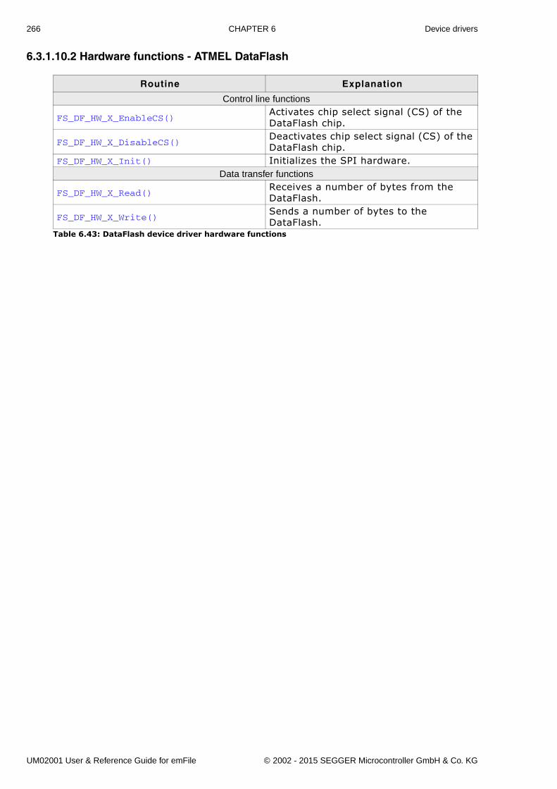
266 CHAPTER 6 Device drivers
6.3.1.10.2 Hardware functions - ATMEL DataFlash
Routine Explanation
Control line functions
FS_DF_HW_X_EnableCS()Activates chip select signal (CS) of the DataFlash chip.
FS_DF_HW_X_DisableCS()Deactivates chip select signal (CS) of the DataFlash chip.
FS_DF_HW_X_Init() Initializes the SPI hardware.Data transfer functions
FS_DF_HW_X_Read()Receives a number of bytes from the DataFlash.
FS_DF_HW_X_Write()Sends a number of bytes to the DataFlash.
Table 6.43: DataFlash device driver hardware functions
UM02001 User & Reference Guide for emFile © 2002 - 2015 SEGGER Microcontroller GmbH & Co. KG
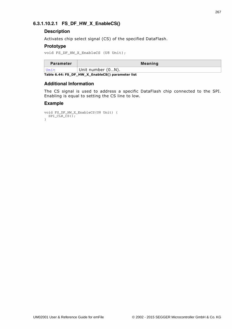
267
6.3.1.10.2.1 FS_DF_HW_X_EnableCS()
Description
Activates chip select signal (CS) of the specified DataFlash.
Prototypevoid FS_DF_HW_X_EnableCS (U8 Unit);
Additional Information
The CS signal is used to address a specific DataFlash chip connected to the SPI.Enabling is equal to setting the CS line to low.
Example
void FS_DF_HW_X_EnableCS(U8 Unit) { SPI_CLR_CS();}
Parameter Meaning
Unit Unit number (0�N).Table 6.44: FS_DF_HW_X_EnableCS() parameter list
UM02001 User & Reference Guide for emFile © 2002 - 2015 SEGGER Microcontroller GmbH & Co. KG
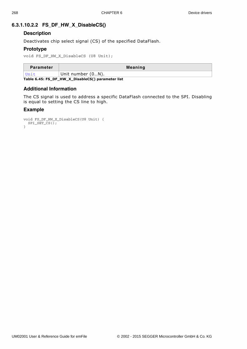
268 CHAPTER 6 Device drivers
6.3.1.10.2.2 FS_DF_HW_X_DisableCS()
Description
Deactivates chip select signal (CS) of the specified DataFlash.
Prototypevoid FS_DF_HW_X_DisableCS (U8 Unit);
Additional Information
The CS signal is used to address a specific DataFlash connected to the SPI. Disablingis equal to setting the CS line to high.
Example
void FS_DF_HW_X_DisableCS(U8 Unit) { SPI_SET_CS();}
Parameter Meaning
Unit Unit number (0�N).Table 6.45: FS_DF_HW_X_DisableCS() parameter list
UM02001 User & Reference Guide for emFile © 2002 - 2015 SEGGER Microcontroller GmbH & Co. KG
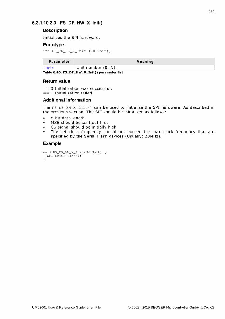
269
6.3.1.10.2.3 FS_DF_HW_X_Init()
Description
Initializes the SPI hardware.
Prototypeint FS_DF_HW_X_Init (U8 Unit);
Return value
== 0 Initialization was successful.== 1 Initialization failed.
Additional Information
The FS_DF_HW_X_Init() can be used to initialize the SPI hardware. As described inthe previous section. The SPI should be initialized as follows:
� 8-bit data length� MSB should be sent out first� CS signal should be initially high� The set clock frequency should not exceed the max clock frequency that are
specified by the Serial Flash devices (Usually: 20MHz).
Example
void FS_DF_HW_X_Init(U8 Unit) { SPI_SETUP_PINS();}
Parameter Meaning
Unit Unit number (0�N).Table 6.46: FS_DF_HW_X_Init() parameter list
UM02001 User & Reference Guide for emFile © 2002 - 2015 SEGGER Microcontroller GmbH & Co. KG
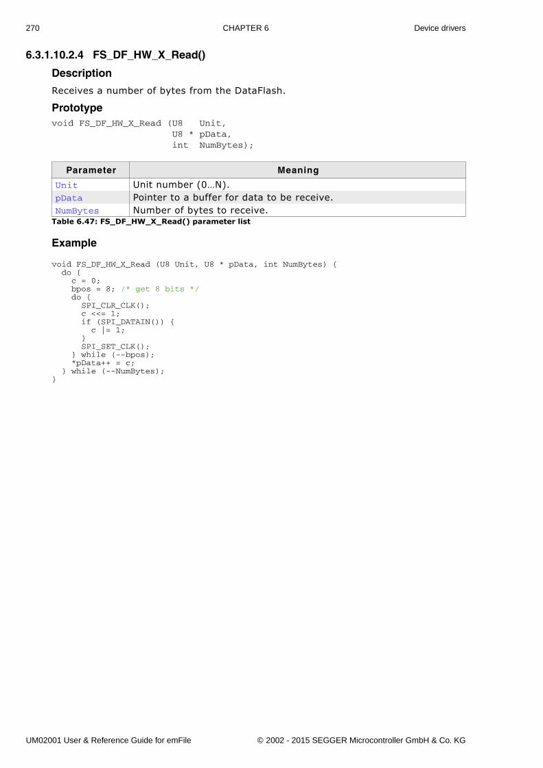
270 CHAPTER 6 Device drivers
6.3.1.10.2.4 FS_DF_HW_X_Read()
Description
Receives a number of bytes from the DataFlash.
Prototypevoid FS_DF_HW_X_Read (U8 Unit, U8 * pData, int NumBytes);
Example
void FS_DF_HW_X_Read (U8 Unit, U8 * pData, int NumBytes) { do { c = 0; bpos = 8; /* get 8 bits */ do { SPI_CLR_CLK(); c <<= 1; if (SPI_DATAIN()) { c |= 1; } SPI_SET_CLK(); } while (--bpos); *pData++ = c; } while (--NumBytes); }
Parameter Meaning
Unit Unit number (0�N).pData Pointer to a buffer for data to be receive.NumBytes Number of bytes to receive.
Table 6.47: FS_DF_HW_X_Read() parameter list
UM02001 User & Reference Guide for emFile © 2002 - 2015 SEGGER Microcontroller GmbH & Co. KG
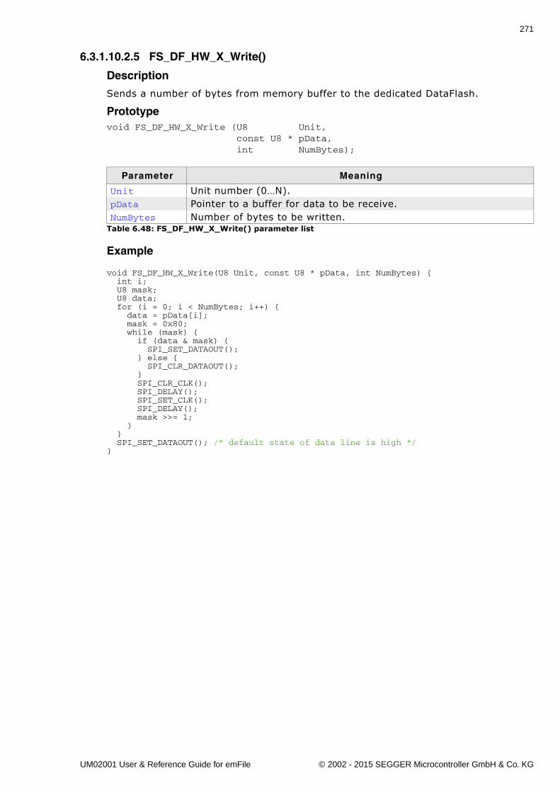
271
6.3.1.10.2.5 FS_DF_HW_X_Write()
Description
Sends a number of bytes from memory buffer to the dedicated DataFlash.
Prototypevoid FS_DF_HW_X_Write (U8 Unit, const U8 * pData, int NumBytes);
Example
void FS_DF_HW_X_Write(U8 Unit, const U8 * pData, int NumBytes) { int i; U8 mask; U8 data; for (i = 0; i < NumBytes; i++) { data = pData[i]; mask = 0x80; while (mask) { if (data & mask) { SPI_SET_DATAOUT(); } else { SPI_CLR_DATAOUT(); } SPI_CLR_CLK(); SPI_DELAY(); SPI_SET_CLK(); SPI_DELAY(); mask >>= 1; } } SPI_SET_DATAOUT(); /* default state of data line is high */ }
Parameter Meaning
Unit Unit number (0�N).pData Pointer to a buffer for data to be receive.NumBytes Number of bytes to be written.
Table 6.48: FS_DF_HW_X_Write() parameter list
UM02001 User & Reference Guide for emFile © 2002 - 2015 SEGGER Microcontroller GmbH & Co. KG
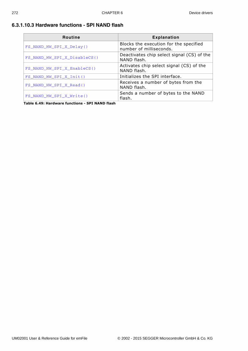
272 CHAPTER 6 Device drivers
6.3.1.10.3 Hardware functions - SPI NAND flash
Routine Explanation
FS_NAND_HW_SPI_X_Delay()Blocks the execution for the specified number of milliseconds.
FS_NAND_HW_SPI_X_DisableCS()Deactivates chip select signal (CS) of the NAND flash.
FS_NAND_HW_SPI_X_EnableCS()Activates chip select signal (CS) of the NAND flash.
FS_NAND_HW_SPI_X_Init() Initializes the SPI interface.
FS_NAND_HW_SPI_X_Read()Receives a number of bytes from the NAND flash.
FS_NAND_HW_SPI_X_Write()Sends a number of bytes to the NAND flash.
Table 6.49: Hardware functions - SPI NAND flash
UM02001 User & Reference Guide for emFile © 2002 - 2015 SEGGER Microcontroller GmbH & Co. KG
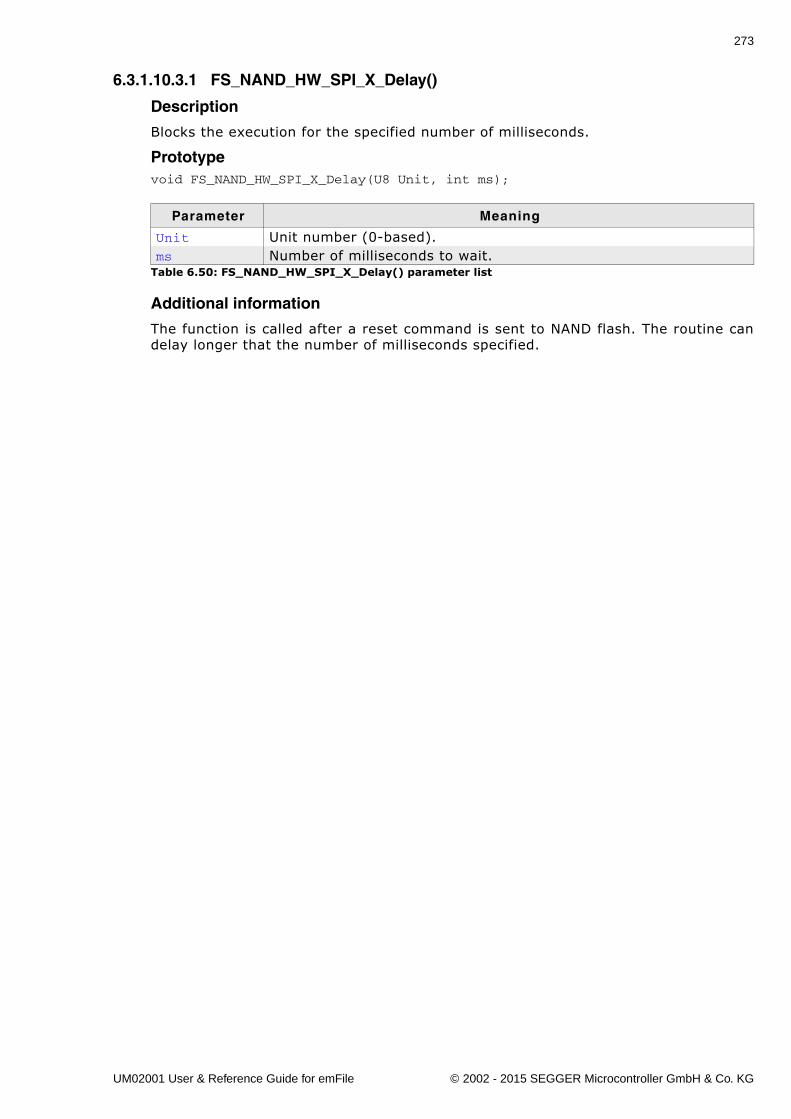
273
6.3.1.10.3.1 FS_NAND_HW_SPI_X_Delay()
Description
Blocks the execution for the specified number of milliseconds.
Prototypevoid FS_NAND_HW_SPI_X_Delay(U8 Unit, int ms);
Additional information
The function is called after a reset command is sent to NAND flash. The routine candelay longer that the number of milliseconds specified.
Parameter Meaning
Unit Unit number (0-based).ms Number of milliseconds to wait.
Table 6.50: FS_NAND_HW_SPI_X_Delay() parameter list
UM02001 User & Reference Guide for emFile © 2002 - 2015 SEGGER Microcontroller GmbH & Co. KG
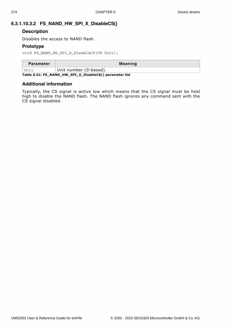
274 CHAPTER 6 Device drivers
6.3.1.10.3.2 FS_NAND_HW_SPI_X_DisableCS()
Description
Disables the access to NAND flash.
Prototypevoid FS_NAND_HW_SPI_X_DisableCS(U8 Unit);
Additional information
Typically, the CS signal is active low which means that the CS signal must be heldhigh to disable the NAND flash. The NAND flash ignores any command sent with theCS signal disabled.
Parameter Meaning
Unit Unit number (0-based).Table 6.51: FS_NAND_HW_SPI_X_DisableCS() parameter list
UM02001 User & Reference Guide for emFile © 2002 - 2015 SEGGER Microcontroller GmbH & Co. KG
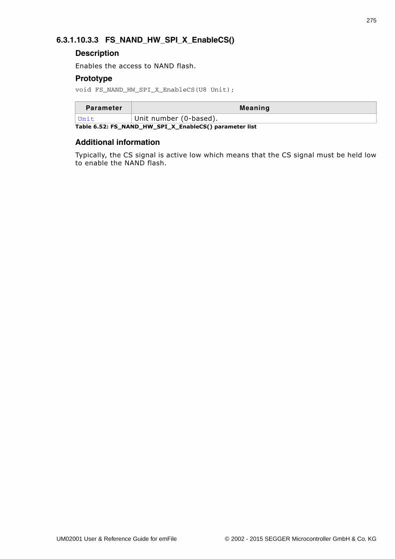
275
6.3.1.10.3.3 FS_NAND_HW_SPI_X_EnableCS()
Description
Enables the access to NAND flash.
Prototypevoid FS_NAND_HW_SPI_X_EnableCS(U8 Unit);
Additional information
Typically, the CS signal is active low which means that the CS signal must be held lowto enable the NAND flash.
Parameter Meaning
Unit Unit number (0-based).Table 6.52: FS_NAND_HW_SPI_X_EnableCS() parameter list
UM02001 User & Reference Guide for emFile © 2002 - 2015 SEGGER Microcontroller GmbH & Co. KG

276 CHAPTER 6 Device drivers
6.3.1.10.3.4 FS_NAND_HW_SPI_X_Init()
Description
Performs the initialization of SPI interface.
Prototypevoid FS_NAND_HW_SPI_X_Init(U8 Unit);
Additional information
This function is called before any other function of the HW layer. It should be used toinitialize the HW.
Parameter Meaning
Unit Unit number (0-based).Table 6.53: FS_NAND_HW_SPI_X_Init() parameter list
UM02001 User & Reference Guide for emFile © 2002 - 2015 SEGGER Microcontroller GmbH & Co. KG
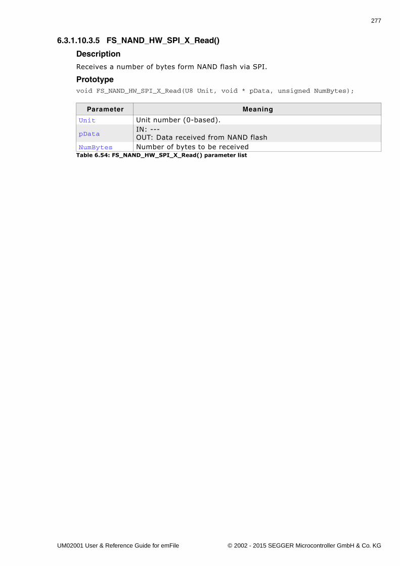
277
6.3.1.10.3.5 FS_NAND_HW_SPI_X_Read()
Description
Receives a number of bytes form NAND flash via SPI.
Prototypevoid FS_NAND_HW_SPI_X_Read(U8 Unit, void * pData, unsigned NumBytes);
Parameter Meaning
Unit Unit number (0-based).
pDataIN: ---OUT: Data received from NAND flash
NumBytes Number of bytes to be receivedTable 6.54: FS_NAND_HW_SPI_X_Read() parameter list
UM02001 User & Reference Guide for emFile © 2002 - 2015 SEGGER Microcontroller GmbH & Co. KG
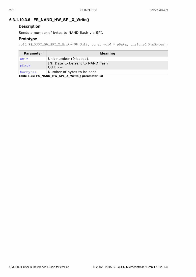
278 CHAPTER 6 Device drivers
6.3.1.10.3.6 FS_NAND_HW_SPI_X_Write()
Description
Sends a number of bytes to NAND flash via SPI.
Prototypevoid FS_NAND_HW_SPI_X_Write(U8 Unit, const void * pData, unsigned NumBytes);
Parameter Meaning
Unit Unit number (0-based).
pDataIN: Data to be sent to NAND flashOUT: ---
NumBytes Number of bytes to be sentTable 6.55: FS_NAND_HW_SPI_X_Write() parameter list
UM02001 User & Reference Guide for emFile © 2002 - 2015 SEGGER Microcontroller GmbH & Co. KG
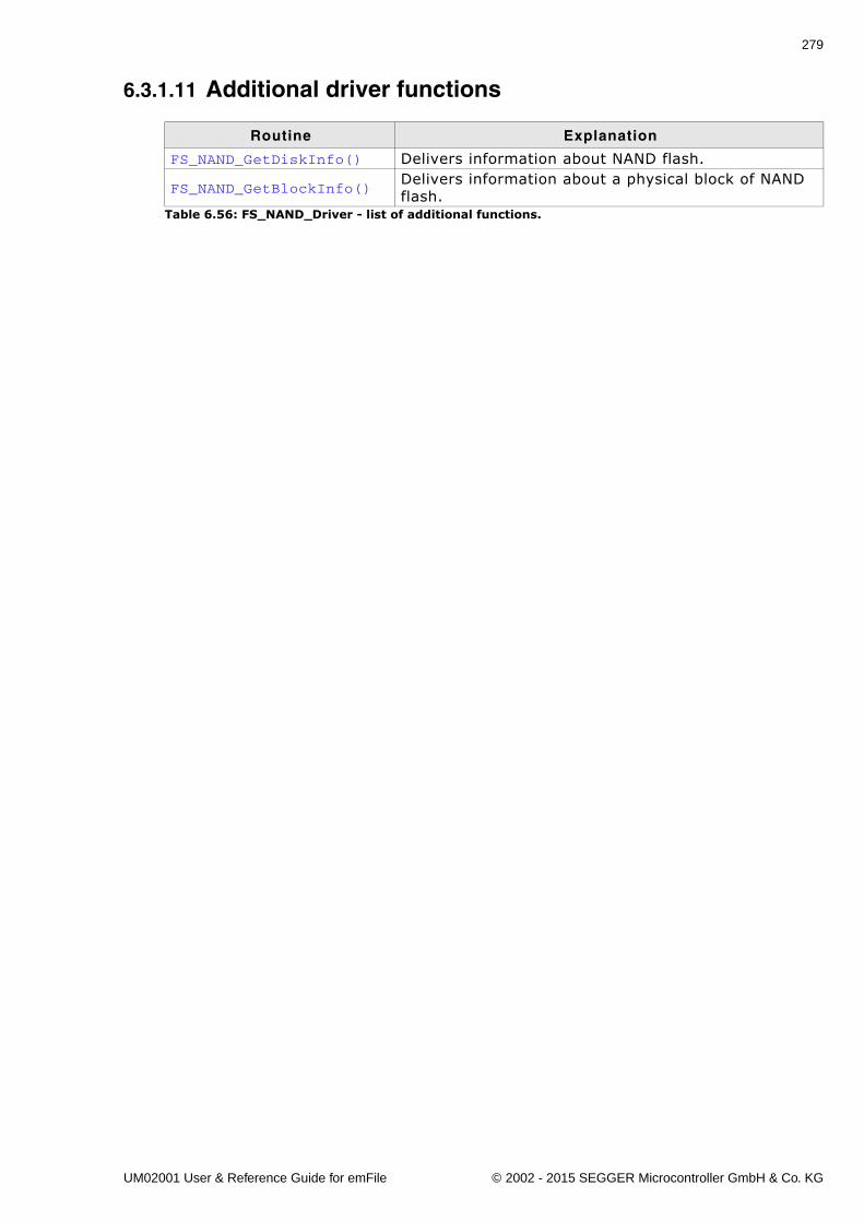
279
6.3.1.11 Additional driver functions
Routine Explanation
FS_NAND_GetDiskInfo() Delivers information about NAND flash.
FS_NAND_GetBlockInfo()Delivers information about a physical block of NAND flash.
Table 6.56: FS_NAND_Driver - list of additional functions.
UM02001 User & Reference Guide for emFile © 2002 - 2015 SEGGER Microcontroller GmbH & Co. KG
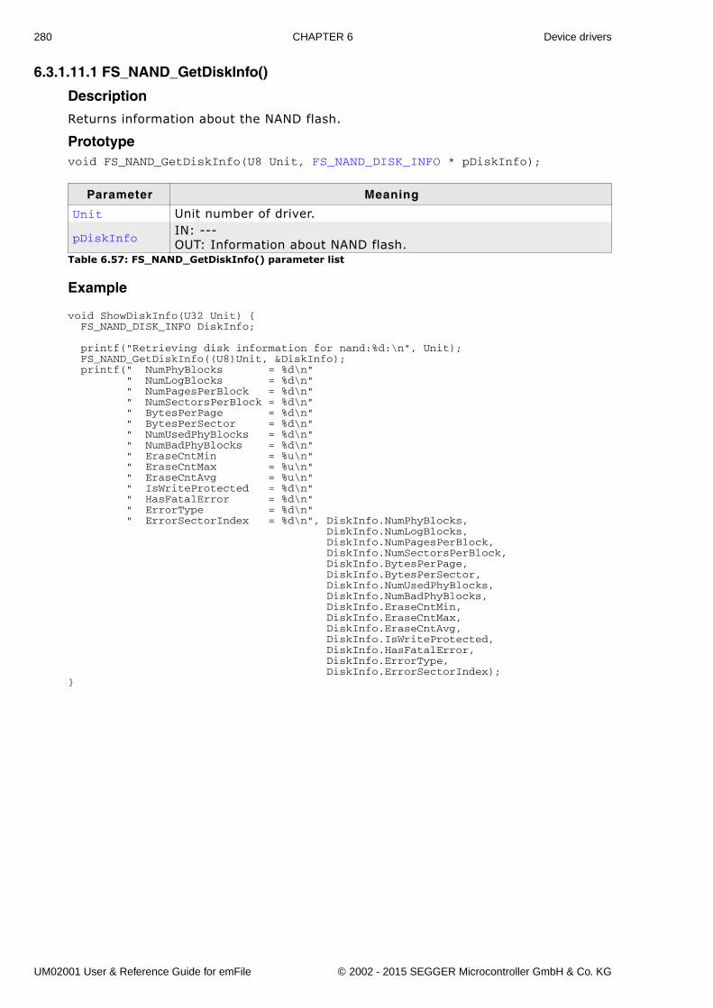
280 CHAPTER 6 Device drivers
6.3.1.11.1 FS_NAND_GetDiskInfo()
Description
Returns information about the NAND flash.
Prototypevoid FS_NAND_GetDiskInfo(U8 Unit, FS_NAND_DISK_INFO * pDiskInfo);
Example
void ShowDiskInfo(U32 Unit) { FS_NAND_DISK_INFO DiskInfo; printf("Retrieving disk information for nand:%d:\n", Unit); FS_NAND_GetDiskInfo((U8)Unit, &DiskInfo); printf(" NumPhyBlocks = %d\n" " NumLogBlocks = %d\n" " NumPagesPerBlock = %d\n" " NumSectorsPerBlock = %d\n" " BytesPerPage = %d\n" " BytesPerSector = %d\n" " NumUsedPhyBlocks = %d\n" " NumBadPhyBlocks = %d\n" " EraseCntMin = %u\n" " EraseCntMax = %u\n" " EraseCntAvg = %u\n" " IsWriteProtected = %d\n" " HasFatalError = %d\n" " ErrorType = %d\n" " ErrorSectorIndex = %d\n", DiskInfo.NumPhyBlocks, DiskInfo.NumLogBlocks, DiskInfo.NumPagesPerBlock, DiskInfo.NumSectorsPerBlock, DiskInfo.BytesPerPage, DiskInfo.BytesPerSector, DiskInfo.NumUsedPhyBlocks, DiskInfo.NumBadPhyBlocks, DiskInfo.EraseCntMin, DiskInfo.EraseCntMax, DiskInfo.EraseCntAvg, DiskInfo.IsWriteProtected, DiskInfo.HasFatalError, DiskInfo.ErrorType, DiskInfo.ErrorSectorIndex);}
Parameter Meaning
Unit Unit number of driver.
pDiskInfoIN: ---OUT: Information about NAND flash.
Table 6.57: FS_NAND_GetDiskInfo() parameter list
UM02001 User & Reference Guide for emFile © 2002 - 2015 SEGGER Microcontroller GmbH & Co. KG
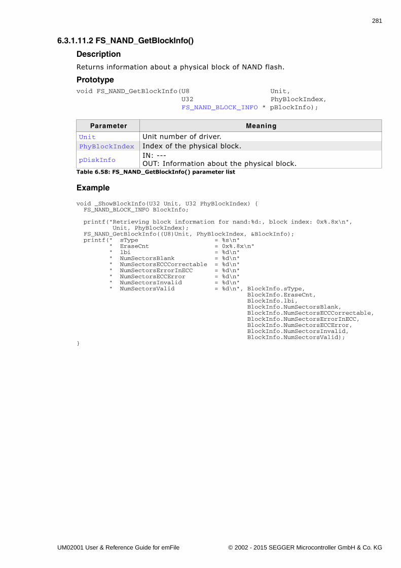
281
6.3.1.11.2 FS_NAND_GetBlockInfo()
Description
Returns information about a physical block of NAND flash.
Prototypevoid FS_NAND_GetBlockInfo(U8 Unit, U32 PhyBlockIndex, FS_NAND_BLOCK_INFO * pBlockInfo);
Example
void _ShowBlockInfo(U32 Unit, U32 PhyBlockIndex) { FS_NAND_BLOCK_INFO BlockInfo; printf("Retrieving block information for nand:%d:, block index: 0x%.8x\n", Unit, PhyBlockIndex); FS_NAND_GetBlockInfo((U8)Unit, PhyBlockIndex, &BlockInfo); printf(" sType = %s\n" " EraseCnt = 0x%.8x\n" " lbi = %d\n" " NumSectorsBlank = %d\n" " NumSectorsECCCorrectable = %d\n" " NumSectorsErrorInECC = %d\n" " NumSectorsECCError = %d\n" " NumSectorsInvalid = %d\n" " NumSectorsValid = %d\n", BlockInfo.sType, BlockInfo.EraseCnt, BlockInfo.lbi, BlockInfo.NumSectorsBlank, BlockInfo.NumSectorsECCCorrectable, BlockInfo.NumSectorsErrorInECC, BlockInfo.NumSectorsECCError, BlockInfo.NumSectorsInvalid, BlockInfo.NumSectorsValid);}
Parameter Meaning
Unit Unit number of driver.PhyBlockIndex Index of the physical block.
pDiskInfoIN: ---OUT: Information about the physical block.
Table 6.58: FS_NAND_GetBlockInfo() parameter list
UM02001 User & Reference Guide for emFile © 2002 - 2015 SEGGER Microcontroller GmbH & Co. KG
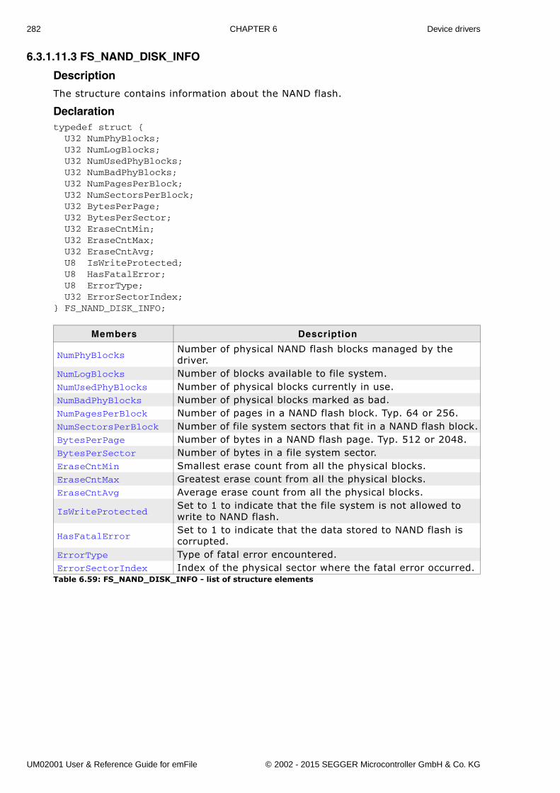
282 CHAPTER 6 Device drivers
6.3.1.11.3 FS_NAND_DISK_INFO
Description
The structure contains information about the NAND flash.
Declarationtypedef struct { U32 NumPhyBlocks; U32 NumLogBlocks; U32 NumUsedPhyBlocks; U32 NumBadPhyBlocks; U32 NumPagesPerBlock; U32 NumSectorsPerBlock; U32 BytesPerPage; U32 BytesPerSector; U32 EraseCntMin; U32 EraseCntMax; U32 EraseCntAvg; U8 IsWriteProtected; U8 HasFatalError; U8 ErrorType; U32 ErrorSectorIndex;} FS_NAND_DISK_INFO;
Members Description
NumPhyBlocksNumber of physical NAND flash blocks managed by the driver.
NumLogBlocks Number of blocks available to file system.NumUsedPhyBlocks Number of physical blocks currently in use.NumBadPhyBlocks Number of physical blocks marked as bad.NumPagesPerBlock Number of pages in a NAND flash block. Typ. 64 or 256.NumSectorsPerBlock Number of file system sectors that fit in a NAND flash block.BytesPerPage Number of bytes in a NAND flash page. Typ. 512 or 2048.BytesPerSector Number of bytes in a file system sector.EraseCntMin Smallest erase count from all the physical blocks.EraseCntMax Greatest erase count from all the physical blocks.EraseCntAvg Average erase count from all the physical blocks.
IsWriteProtectedSet to 1 to indicate that the file system is not allowed to write to NAND flash.
HasFatalErrorSet to 1 to indicate that the data stored to NAND flash is corrupted.
ErrorType Type of fatal error encountered.ErrorSectorIndex Index of the physical sector where the fatal error occurred.
Table 6.59: FS_NAND_DISK_INFO - list of structure elements
UM02001 User & Reference Guide for emFile © 2002 - 2015 SEGGER Microcontroller GmbH & Co. KG
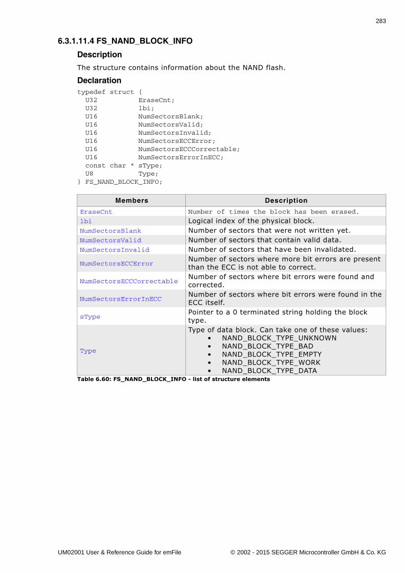
283
6.3.1.11.4 FS_NAND_BLOCK_INFO
Description
The structure contains information about the NAND flash.
Declarationtypedef struct { U32 EraseCnt; U32 lbi; U16 NumSectorsBlank; U16 NumSectorsValid; U16 NumSectorsInvalid; U16 NumSectorsECCError; U16 NumSectorsECCCorrectable; U16 NumSectorsErrorInECC; const char * sType; U8 Type;} FS_NAND_BLOCK_INFO;
Members Description
EraseCnt Number of times the block has been erased.
lbi Logical index of the physical block.NumSectorsBlank Number of sectors that were not written yet.NumSectorsValid Number of sectors that contain valid data.NumSectorsInvalid Number of sectors that have been invalidated.
NumSectorsECCErrorNumber of sectors where more bit errors are present than the ECC is not able to correct.
NumSectorsECCCorrectableNumber of sectors where bit errors were found and corrected.
NumSectorsErrorInECCNumber of sectors where bit errors were found in the ECC itself.
sTypePointer to a 0 terminated string holding the block type.
Type
Type of data block. Can take one of these values:� NAND_BLOCK_TYPE_UNKNOWN� NAND_BLOCK_TYPE_BAD� NAND_BLOCK_TYPE_EMPTY� NAND_BLOCK_TYPE_WORK� NAND_BLOCK_TYPE_DATA
Table 6.60: FS_NAND_BLOCK_INFO - list of structure elements
UM02001 User & Reference Guide for emFile © 2002 - 2015 SEGGER Microcontroller GmbH & Co. KG
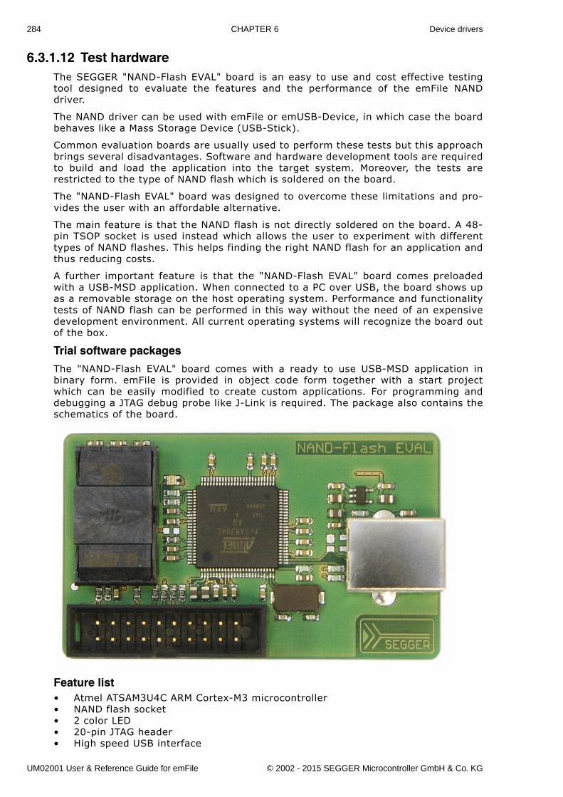
284 CHAPTER 6 Device drivers
6.3.1.12 Test hardwareThe SEGGER "NAND-Flash EVAL" board is an easy to use and cost effective testingtool designed to evaluate the features and the performance of the emFile NANDdriver.
The NAND driver can be used with emFile or emUSB-Device, in which case the boardbehaves like a Mass Storage Device (USB-Stick).
Common evaluation boards are usually used to perform these tests but this approachbrings several disadvantages. Software and hardware development tools are requiredto build and load the application into the target system. Moreover, the tests arerestricted to the type of NAND flash which is soldered on the board.
The "NAND-Flash EVAL" board was designed to overcome these limitations and pro-vides the user with an affordable alternative.
The main feature is that the NAND flash is not directly soldered on the board. A 48-pin TSOP socket is used instead which allows the user to experiment with differenttypes of NAND flashes. This helps finding the right NAND flash for an application andthus reducing costs.
A further important feature is that the "NAND-Flash EVAL" board comes preloadedwith a USB-MSD application. When connected to a PC over USB, the board shows upas a removable storage on the host operating system. Performance and functionalitytests of NAND flash can be performed in this way without the need of an expensivedevelopment environment. All current operating systems will recognize the board outof the box.
Trial software packages
The "NAND-Flash EVAL" board comes with a ready to use USB-MSD application inbinary form. emFile is provided in object code form together with a start projectwhich can be easily modified to create custom applications. For programming anddebugging a JTAG debug probe like J-Link is required. The package also contains theschematics of the board.
Feature list� Atmel ATSAM3U4C ARM Cortex-M3 microcontroller� NAND flash socket� 2 color LED� 20-pin JTAG header� High speed USB interface
UM02001 User & Reference Guide for emFile © 2002 - 2015 SEGGER Microcontroller GmbH & Co. KG
285
� USB powered
UM02001 User & Reference Guide for emFile © 2002 - 2015 SEGGER Microcontroller GmbH & Co. KG
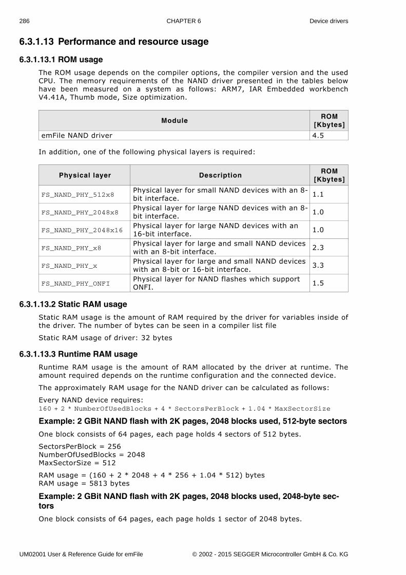
286 CHAPTER 6 Device drivers
6.3.1.13 Performance and resource usage
6.3.1.13.1 ROM usage
The ROM usage depends on the compiler options, the compiler version and the usedCPU. The memory requirements of the NAND driver presented in the tables belowhave been measured on a system as follows: ARM7, IAR Embedded workbenchV4.41A, Thumb mode, Size optimization.
In addition, one of the following physical layers is required:
6.3.1.13.2 Static RAM usage
Static RAM usage is the amount of RAM required by the driver for variables inside ofthe driver. The number of bytes can be seen in a compiler list file
Static RAM usage of driver: 32 bytes
6.3.1.13.3 Runtime RAM usage
Runtime RAM usage is the amount of RAM allocated by the driver at runtime. Theamount required depends on the runtime configuration and the connected device.
The approximately RAM usage for the NAND driver can be calculated as follows:
Every NAND device requires:160 + 2 * NumberOfUsedBlocks + 4 * SectorsPerBlock + 1.04 * MaxSectorSize
Example: 2 GBit NAND flash with 2K pages, 2048 blocks used, 512-byte sectors
One block consists of 64 pages, each page holds 4 sectors of 512 bytes.
SectorsPerBlock = 256NumberOfUsedBlocks = 2048MaxSectorSize = 512
RAM usage = (160 + 2 * 2048 + 4 * 256 + 1.04 * 512) bytesRAM usage = 5813 bytes
Example: 2 GBit NAND flash with 2K pages, 2048 blocks used, 2048-byte sec-tors
One block consists of 64 pages, each page holds 1 sector of 2048 bytes.
ModuleROM
[Kbytes]
emFile NAND driver 4.5
Physical layer DescriptionROM
[Kbytes]
FS_NAND_PHY_512x8Physical layer for small NAND devices with an 8-bit interface. 1.1
FS_NAND_PHY_2048x8Physical layer for large NAND devices with an 8-bit interface. 1.0
FS_NAND_PHY_2048x16Physical layer for large NAND devices with an 16-bit interface. 1.0
FS_NAND_PHY_x8Physical layer for large and small NAND devices with an 8-bit interface. 2.3
FS_NAND_PHY_xPhysical layer for large and small NAND devices with an 8-bit or 16-bit interface. 3.3
FS_NAND_PHY_ONFIPhysical layer for NAND flashes which support ONFI. 1.5
UM02001 User & Reference Guide for emFile © 2002 - 2015 SEGGER Microcontroller GmbH & Co. KG
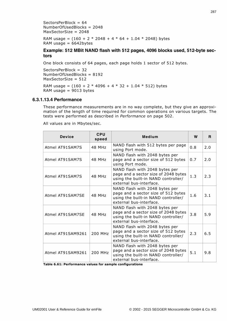
287
SectorsPerBlock = 64NumberOfUsedBlocks = 2048MaxSectorSize = 2048
RAM usage = (160 + 2 * 2048 + 4 * 64 + 1.04 * 2048) bytesRAM usage = 6642bytes
Example: 512 MBit NAND flash with 512 pages, 4096 blocks used, 512-byte sec-tors
One block consists of 64 pages, each page holds 1 sector of 512 bytes.
SectorsPerBlock = 32NumberOfUsedBlocks = 8192MaxSectorSize = 512
RAM usage = (160 + 2 * 4096 + 4 * 32 + 1.04 * 512) bytesRAM usage = 9013 bytes
6.3.1.13.4 Performance
These performance measurements are in no way complete, but they give an approxi-mation of the length of time required for common operations on various targets. Thetests were performed as described in Performance on page 502.
All values are in Mbytes/sec.
DeviceCPU
speedMedium W R
Atmel AT91SAM7S 48 MHz NAND flash with 512 bytes per page using Port mode. 0.8 2.0
Atmel AT91SAM7S 48 MHzNAND flash with 2048 bytes per page and a sector size of 512 bytes using Port mode.
0.7 2.0
Atmel AT91SAM7S 48 MHz
NAND flash with 2048 bytes per page and a sector size of 2048 bytes using the built-in NAND controller/external bus-interface.
1.3 2.3
Atmel AT91SAM7SE 48 MHz
NAND flash with 2048 bytes per page and a sector size of 512 bytes using the built-in NAND controller/external bus-interface.
1.6 3.1
Atmel AT91SAM7SE 48 MHz
NAND flash with 2048 bytes per page and a sector size of 2048 bytes using the built-in NAND controller/external bus-interface.
3.8 5.9
Atmel AT91SAM9261 200 MHz
NAND flash with 2048 bytes per page and a sector size of 512 bytes using the built-in NAND controller/external bus-interface.
2.3 6.5
Atmel AT91SAM9261 200 MHz
NAND flash with 2048 bytes per page and a sector size of 2048 bytes using the built-in NAND controller/external bus-interface.
5.1 9.8
Table 6.61: Performance values for sample configurations
UM02001 User & Reference Guide for emFile © 2002 - 2015 SEGGER Microcontroller GmbH & Co. KG
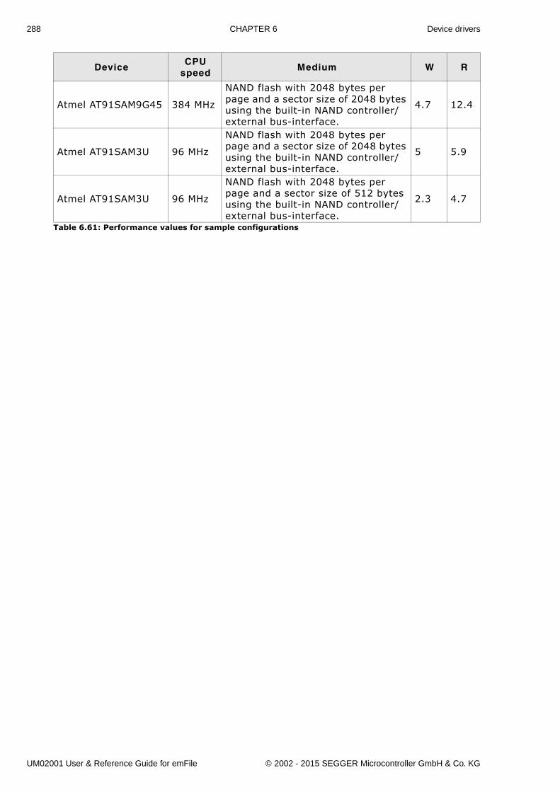
288 CHAPTER 6 Device drivers
Atmel AT91SAM9G45 384 MHz
NAND flash with 2048 bytes per page and a sector size of 2048 bytes using the built-in NAND controller/external bus-interface.
4.7 12.4
Atmel AT91SAM3U 96 MHz
NAND flash with 2048 bytes per page and a sector size of 2048 bytes using the built-in NAND controller/external bus-interface.
5 5.9
Atmel AT91SAM3U 96 MHz
NAND flash with 2048 bytes per page and a sector size of 512 bytes using the built-in NAND controller/external bus-interface.
2.3 4.7
DeviceCPU
speedMedium W R
Table 6.61: Performance values for sample configurations
UM02001 User & Reference Guide for emFile © 2002 - 2015 SEGGER Microcontroller GmbH & Co. KG
289
6.3.1.14 FAQsQ: Are Multi-Level Cell NAND flashes (MLCs) supported?A: Yes, the Universal NAND driver does support MLCs.
Q: Are NAND flashes with 4-Kbytes pages supported?A: Yes, they are supported. The FS_NAND_PHY_4096x8 physical layer should be used.
UM02001 User & Reference Guide for emFile © 2002 - 2015 SEGGER Microcontroller GmbH & Co. KG
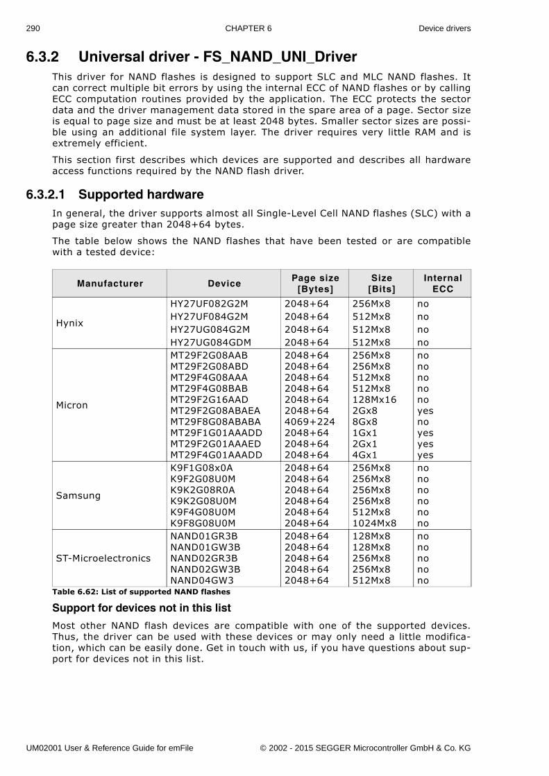
290 CHAPTER 6 Device drivers
6.3.2 Universal driver - FS_NAND_UNI_DriverThis driver for NAND flashes is designed to support SLC and MLC NAND flashes. Itcan correct multiple bit errors by using the internal ECC of NAND flashes or by callingECC computation routines provided by the application. The ECC protects the sectordata and the driver management data stored in the spare area of a page. Sector sizeis equal to page size and must be at least 2048 bytes. Smaller sector sizes are possi-ble using an additional file system layer. The driver requires very little RAM and isextremely efficient.
This section first describes which devices are supported and describes all hardwareaccess functions required by the NAND flash driver.
6.3.2.1 Supported hardwareIn general, the driver supports almost all Single-Level Cell NAND flashes (SLC) with apage size greater than 2048+64 bytes.
The table below shows the NAND flashes that have been tested or are compatiblewith a tested device:
Support for devices not in this list
Most other NAND flash devices are compatible with one of the supported devices.Thus, the driver can be used with these devices or may only need a little modifica-tion, which can be easily done. Get in touch with us, if you have questions about sup-port for devices not in this list.
Manufacturer DevicePage size
[Bytes]Size
[Bits]Internal
ECC
Hynix
HY27UF082G2M 2048+64 256Mx8 noHY27UF084G2M 2048+64 512Mx8 noHY27UG084G2M 2048+64 512Mx8 noHY27UG084GDM 2048+64 512Mx8 no
Micron
MT29F2G08AABMT29F2G08ABDMT29F4G08AAAMT29F4G08BABMT29F2G16AADMT29F2G08ABAEAMT29F8G08ABABAMT29F1G01AAADDMT29F2G01AAAEDMT29F4G01AAADD
2048+642048+642048+642048+642048+642048+644069+2242048+642048+642048+64
256Mx8256Mx8512Mx8512Mx8128Mx162Gx88Gx81Gx12Gx14Gx1
nononononoyesnoyesyesyes
Samsung
K9F1G08x0AK9F2G08U0MK9K2G08R0AK9K2G08U0MK9F4G08U0MK9F8G08U0M
2048+642048+642048+642048+642048+642048+64
256Mx8256Mx8256Mx8256Mx8512Mx81024Mx8
nononononono
ST-Microelectronics
NAND01GR3BNAND01GW3BNAND02GR3BNAND02GW3BNAND04GW3
2048+642048+642048+642048+642048+64
128Mx8128Mx8256Mx8256Mx8512Mx8
nonononono
Table 6.62: List of supported NAND flashes
UM02001 User & Reference Guide for emFile © 2002 - 2015 SEGGER Microcontroller GmbH & Co. KG
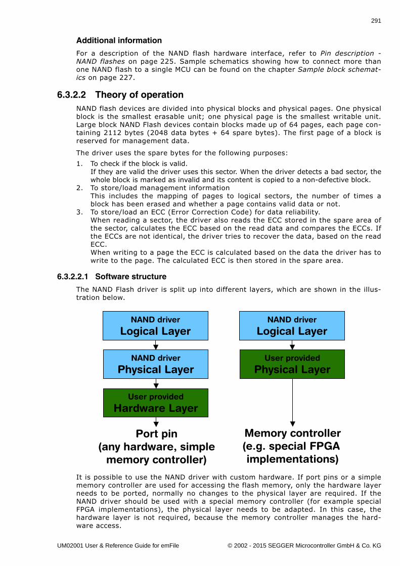
291
Additional information
For a description of the NAND flash hardware interface, refer to Pin description -NAND flashes on page 225. Sample schematics showing how to connect more thanone NAND flash to a single MCU can be found on the chapter Sample block schemat-ics on page 227.
6.3.2.2 Theory of operationNAND flash devices are divided into physical blocks and physical pages. One physicalblock is the smallest erasable unit; one physical page is the smallest writable unit.Large block NAND Flash devices contain blocks made up of 64 pages, each page con-taining 2112 bytes (2048 data bytes + 64 spare bytes). The first page of a block isreserved for management data.
The driver uses the spare bytes for the following purposes:
1. To check if the block is valid.If they are valid the driver uses this sector. When the driver detects a bad sector, thewhole block is marked as invalid and its content is copied to a non-defective block.
2. To store/load management informationThis includes the mapping of pages to logical sectors, the number of times ablock has been erased and whether a page contains valid data or not.
3. To store/load an ECC (Error Correction Code) for data reliability.When reading a sector, the driver also reads the ECC stored in the spare area ofthe sector, calculates the ECC based on the read data and compares the ECCs. Ifthe ECCs are not identical, the driver tries to recover the data, based on the readECC.When writing to a page the ECC is calculated based on the data the driver has towrite to the page. The calculated ECC is then stored in the spare area.
6.3.2.2.1 Software structure
The NAND Flash driver is split up into different layers, which are shown in the illus-tration below.
It is possible to use the NAND driver with custom hardware. If port pins or a simplememory controller are used for accessing the flash memory, only the hardware layerneeds to be ported, normally no changes to the physical layer are required. If theNAND driver should be used with a special memory controller (for example specialFPGA implementations), the physical layer needs to be adapted. In this case, thehardware layer is not required, because the memory controller manages the hard-ware access.
NAND driver
Logical Layer
NAND driver
Physical Layer
User provided
Hardware Layer
NAND driver
Logical Layer
User provided
Physical Layer
Port pin(any hardware, simple
memory controller)
Memory controller(e.g. special FPGA implementations)
UM02001 User & Reference Guide for emFile © 2002 - 2015 SEGGER Microcontroller GmbH & Co. KG
292 CHAPTER 6 Device drivers
6.3.2.3 Fail-safe operationThe emFile NAND driver is fail-safe. That means that the driver makes only atomicactions and takes the responsibility that the data managed by the file system isalways valid. In case of a power loss or a power reset during a write operation, it isalways assured that only valid data is stored in the flash. If the power loss interruptsthe write operation, the old data will be kept and the data is not corrupted.
For additional information, refer to Fail-safe operation on page 228.
6.3.2.4 Wear levelingWear leveling is supported by the driver. The procedure ensures that the number oferase cycles remains approximately for all the blocks. The maximum allowed erasecount difference is runtime configurable and is by default 5000.
6.3.2.5 Partial writesThe driver writes only once in any page of the NAND flash between two block erasecycles. The number of partial writes is 1 making the driver conform with any SLC/MLC device.
UM02001 User & Reference Guide for emFile © 2002 - 2015 SEGGER Microcontroller GmbH & Co. KG
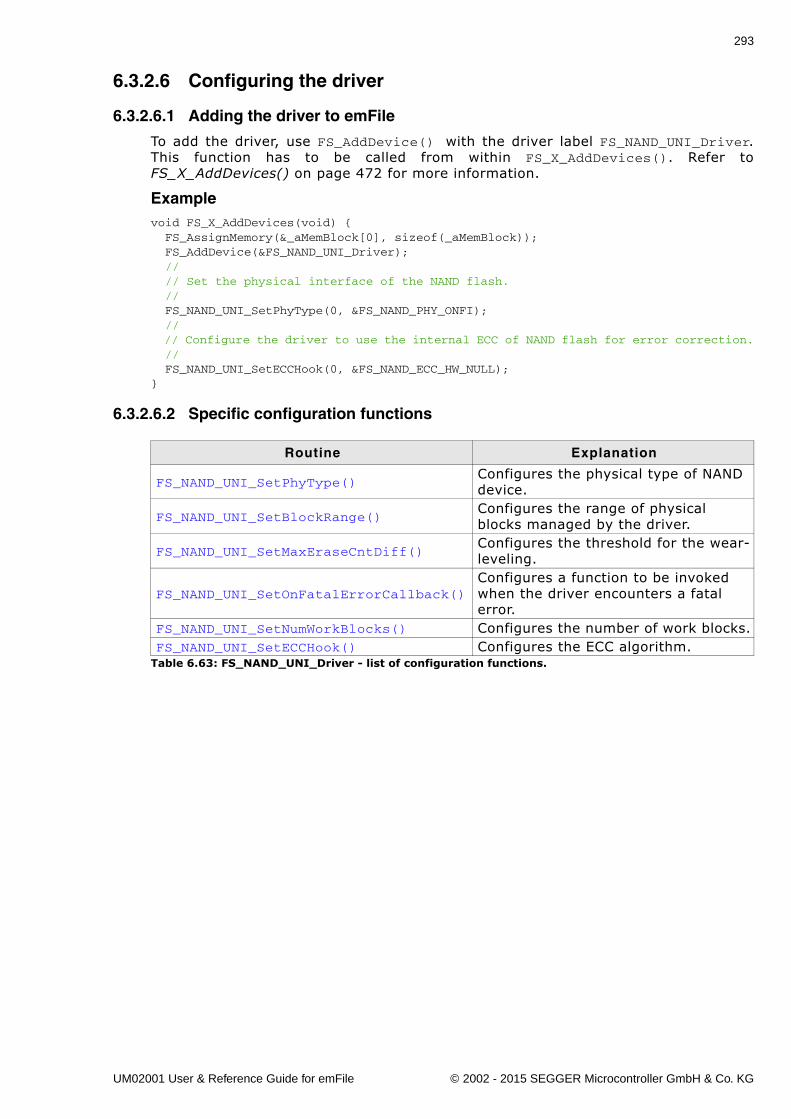
293
6.3.2.6 Configuring the driver
6.3.2.6.1 Adding the driver to emFile
To add the driver, use FS_AddDevice() with the driver label FS_NAND_UNI_Driver.This function has to be called from within FS_X_AddDevices(). Refer toFS_X_AddDevices() on page 472 for more information.
Examplevoid FS_X_AddDevices(void) { FS_AssignMemory(&_aMemBlock[0], sizeof(_aMemBlock)); FS_AddDevice(&FS_NAND_UNI_Driver); // // Set the physical interface of the NAND flash. // FS_NAND_UNI_SetPhyType(0, &FS_NAND_PHY_ONFI); // // Configure the driver to use the internal ECC of NAND flash for error correction. // FS_NAND_UNI_SetECCHook(0, &FS_NAND_ECC_HW_NULL);}
6.3.2.6.2 Specific configuration functions
Routine Explanation
FS_NAND_UNI_SetPhyType()Configures the physical type of NAND device.
FS_NAND_UNI_SetBlockRange()Configures the range of physical blocks managed by the driver.
FS_NAND_UNI_SetMaxEraseCntDiff()Configures the threshold for the wear-leveling.
FS_NAND_UNI_SetOnFatalErrorCallback()Configures a function to be invoked when the driver encounters a fatal error.
FS_NAND_UNI_SetNumWorkBlocks() Configures the number of work blocks.FS_NAND_UNI_SetECCHook() Configures the ECC algorithm.
Table 6.63: FS_NAND_UNI_Driver - list of configuration functions.
UM02001 User & Reference Guide for emFile © 2002 - 2015 SEGGER Microcontroller GmbH & Co. KG
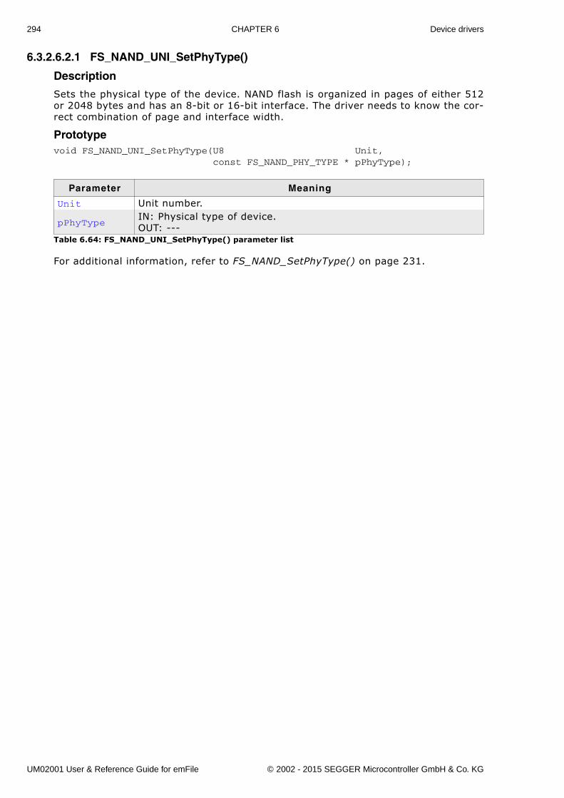
294 CHAPTER 6 Device drivers
6.3.2.6.2.1 FS_NAND_UNI_SetPhyType()
Description
Sets the physical type of the device. NAND flash is organized in pages of either 512or 2048 bytes and has an 8-bit or 16-bit interface. The driver needs to know the cor-rect combination of page and interface width.
Prototypevoid FS_NAND_UNI_SetPhyType(U8 Unit, const FS_NAND_PHY_TYPE * pPhyType);
For additional information, refer to FS_NAND_SetPhyType() on page 231.
Parameter Meaning
Unit Unit number.
pPhyTypeIN: Physical type of device.OUT: ---
Table 6.64: FS_NAND_UNI_SetPhyType() parameter list
UM02001 User & Reference Guide for emFile © 2002 - 2015 SEGGER Microcontroller GmbH & Co. KG
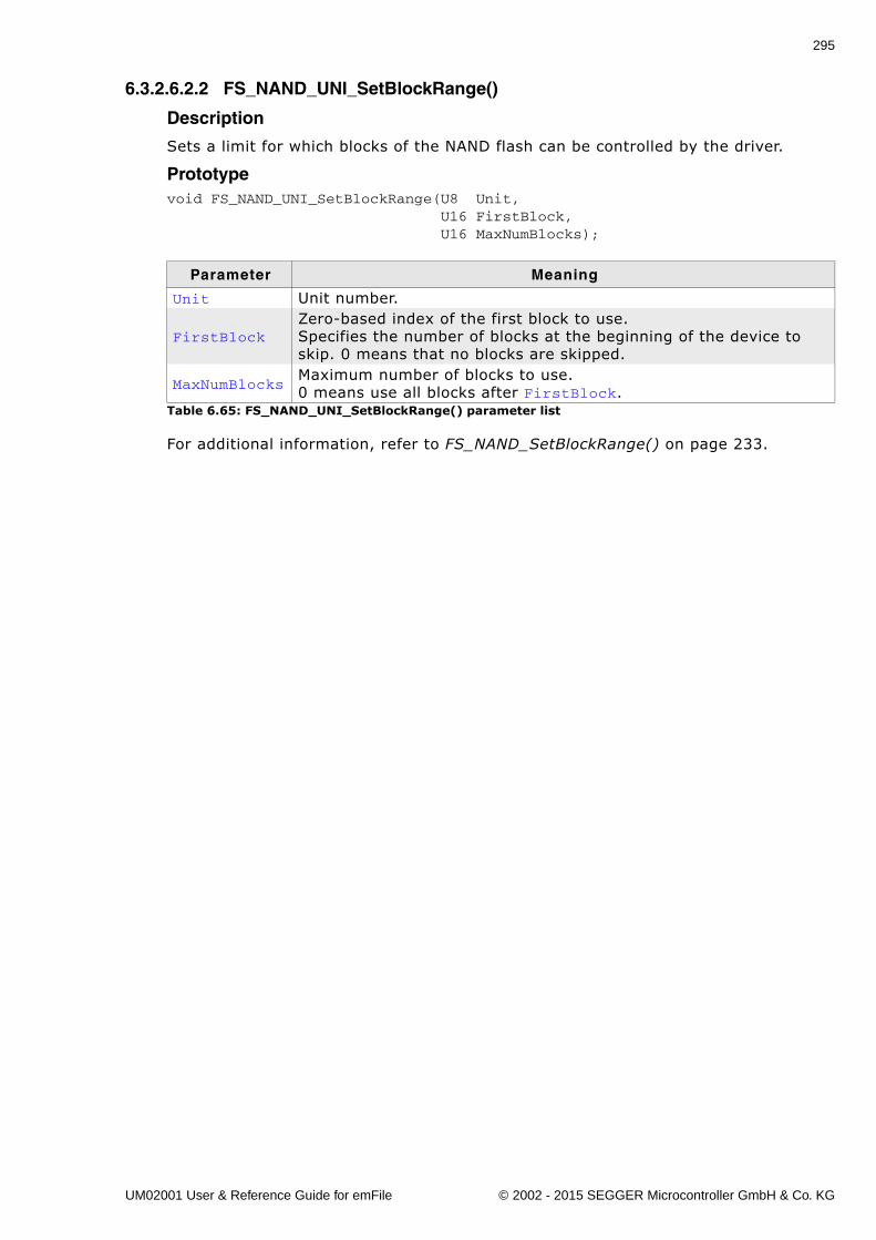
295
6.3.2.6.2.2 FS_NAND_UNI_SetBlockRange()
Description
Sets a limit for which blocks of the NAND flash can be controlled by the driver.
Prototypevoid FS_NAND_UNI_SetBlockRange(U8 Unit, U16 FirstBlock, U16 MaxNumBlocks);
For additional information, refer to FS_NAND_SetBlockRange() on page 233.
Parameter Meaning
Unit Unit number.
FirstBlockZero-based index of the first block to use. Specifies the number of blocks at the beginning of the device to skip. 0 means that no blocks are skipped.
MaxNumBlocksMaximum number of blocks to use.0 means use all blocks after FirstBlock.
Table 6.65: FS_NAND_UNI_SetBlockRange() parameter list
UM02001 User & Reference Guide for emFile © 2002 - 2015 SEGGER Microcontroller GmbH & Co. KG
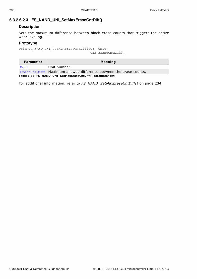
296 CHAPTER 6 Device drivers
6.3.2.6.2.3 FS_NAND_UNI_SetMaxEraseCntDiff()
Description
Sets the maximum difference between block erase counts that triggers the activewear leveling.
Prototypevoid FS_NAND_UNI_SetMaxEraseCntDiff(U8 Unit, U32 EraseCntDiff);
For additional information, refer to FS_NAND_SetMaxEraseCntDiff() on page 234.
Parameter Meaning
Unit Unit number.EraseCntDiff Maximum allowed difference between the erase counts.
Table 6.66: FS_NAND_UNI_SetMaxEraseCntDiff() parameter list
UM02001 User & Reference Guide for emFile © 2002 - 2015 SEGGER Microcontroller GmbH & Co. KG
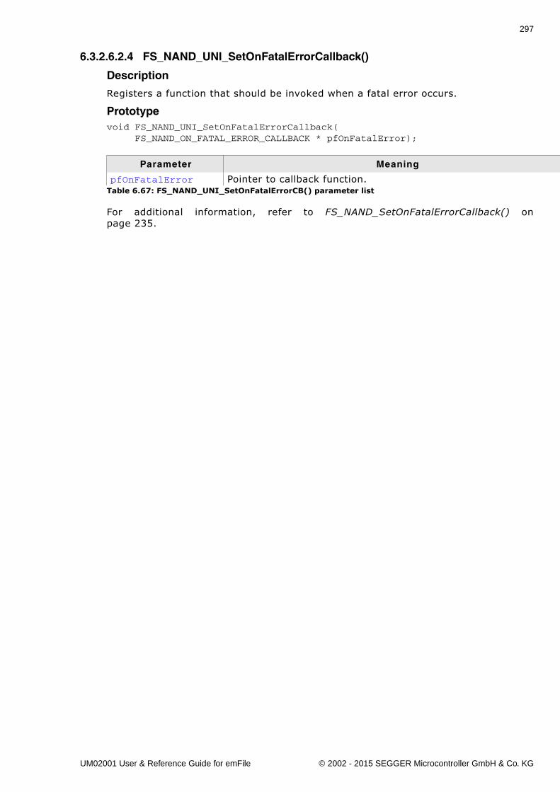
297
6.3.2.6.2.4 FS_NAND_UNI_SetOnFatalErrorCallback()
Description
Registers a function that should be invoked when a fatal error occurs.
Prototypevoid FS_NAND_UNI_SetOnFatalErrorCallback( FS_NAND_ON_FATAL_ERROR_CALLBACK * pfOnFatalError);
For additional information, refer to FS_NAND_SetOnFatalErrorCallback() onpage 235.
Parameter Meaning
pfOnFatalError Pointer to callback function.Table 6.67: FS_NAND_UNI_SetOnFatalErrorCB() parameter list
UM02001 User & Reference Guide for emFile © 2002 - 2015 SEGGER Microcontroller GmbH & Co. KG
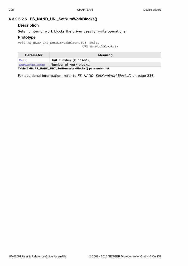
298 CHAPTER 6 Device drivers
6.3.2.6.2.5 FS_NAND_UNI_SetNumWorkBlocks()
Description
Sets number of work blocks the driver uses for write operations.
Prototypevoid FS_NAND_UNI_SetNumWorkBlocks(U8 Unit, U32 NumWorkBlocks);
For additional information, refer to FS_NAND_SetNumWorkBlocks() on page 236.
Parameter Meaning
Unit Unit number (0 based).NumWorkBlocks Number of work blocks.
Table 6.68: FS_NAND_UNI_SetNumWorkBlocks() parameter list
UM02001 User & Reference Guide for emFile © 2002 - 2015 SEGGER Microcontroller GmbH & Co. KG
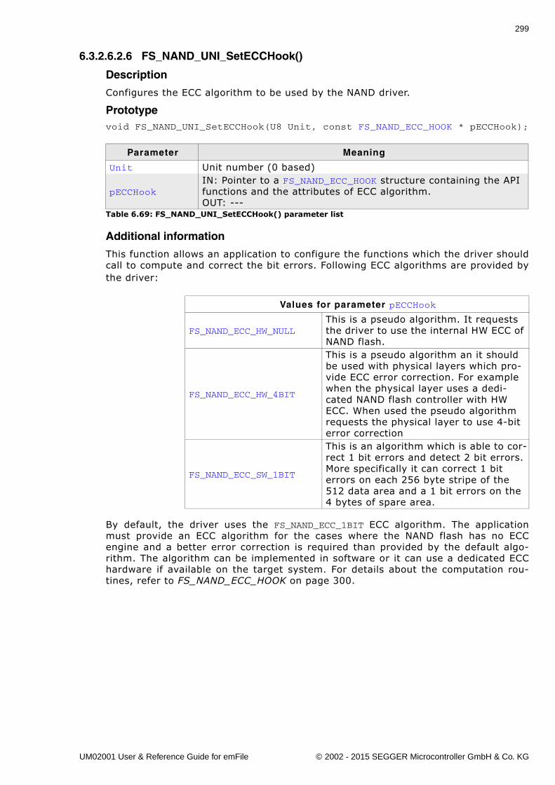
299
6.3.2.6.2.6 FS_NAND_UNI_SetECCHook()
Description
Configures the ECC algorithm to be used by the NAND driver.
Prototypevoid FS_NAND_UNI_SetECCHook(U8 Unit, const FS_NAND_ECC_HOOK * pECCHook);
Additional information
This function allows an application to configure the functions which the driver shouldcall to compute and correct the bit errors. Following ECC algorithms are provided bythe driver:
By default, the driver uses the FS_NAND_ECC_1BIT ECC algorithm. The applicationmust provide an ECC algorithm for the cases where the NAND flash has no ECCengine and a better error correction is required than provided by the default algo-rithm. The algorithm can be implemented in software or it can use a dedicated ECChardware if available on the target system. For details about the computation rou-tines, refer to FS_NAND_ECC_HOOK on page 300.
Parameter Meaning
Unit Unit number (0 based)
pECCHookIN: Pointer to a FS_NAND_ECC_HOOK structure containing the API functions and the attributes of ECC algorithm.OUT: ---
Table 6.69: FS_NAND_UNI_SetECCHook() parameter list
Values for parameter pECCHook
FS_NAND_ECC_HW_NULLThis is a pseudo algorithm. It requests the driver to use the internal HW ECC of NAND flash.
FS_NAND_ECC_HW_4BIT
This is a pseudo algorithm an it should be used with physical layers which pro-vide ECC error correction. For example when the physical layer uses a dedi-cated NAND flash controller with HW ECC. When used the pseudo algorithm requests the physical layer to use 4-bit error correction
FS_NAND_ECC_SW_1BIT
This is an algorithm which is able to cor-rect 1 bit errors and detect 2 bit errors. More specifically it can correct 1 bit errors on each 256 byte stripe of the 512 data area and a 1 bit errors on the 4 bytes of spare area.
UM02001 User & Reference Guide for emFile © 2002 - 2015 SEGGER Microcontroller GmbH & Co. KG
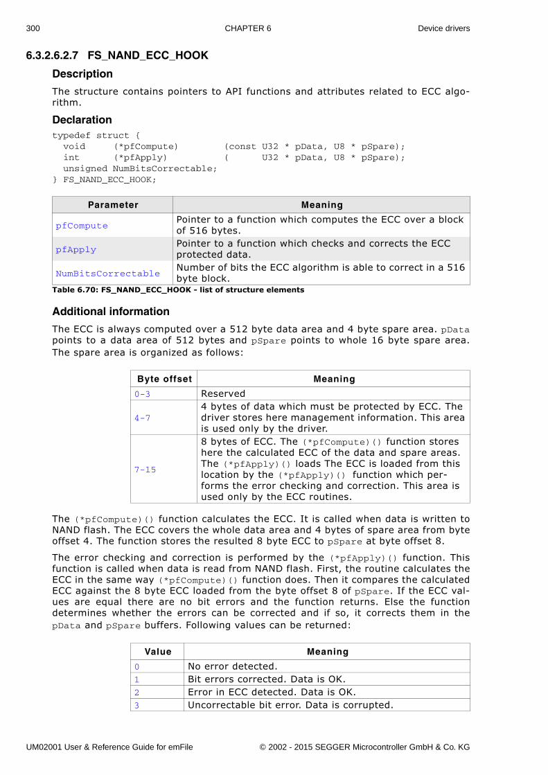
300 CHAPTER 6 Device drivers
6.3.2.6.2.7 FS_NAND_ECC_HOOK
Description
The structure contains pointers to API functions and attributes related to ECC algo-rithm.
Declarationtypedef struct { void (*pfCompute) (const U32 * pData, U8 * pSpare); int (*pfApply) ( U32 * pData, U8 * pSpare); unsigned NumBitsCorrectable;} FS_NAND_ECC_HOOK;
Additional information
The ECC is always computed over a 512 byte data area and 4 byte spare area. pDatapoints to a data area of 512 bytes and pSpare points to whole 16 byte spare area.The spare area is organized as follows:
The (*pfCompute)() function calculates the ECC. It is called when data is written toNAND flash. The ECC covers the whole data area and 4 bytes of spare area from byteoffset 4. The function stores the resulted 8 byte ECC to pSpare at byte offset 8.
The error checking and correction is performed by the (*pfApply)() function. Thisfunction is called when data is read from NAND flash. First, the routine calculates theECC in the same way (*pfCompute)() function does. Then it compares the calculatedECC against the 8 byte ECC loaded from the byte offset 8 of pSpare. If the ECC val-ues are equal there are no bit errors and the function returns. Else the functiondetermines whether the errors can be corrected and if so, it corrects them in thepData and pSpare buffers. Following values can be returned:
Parameter Meaning
pfComputePointer to a function which computes the ECC over a block of 516 bytes.
pfApplyPointer to a function which checks and corrects the ECC protected data.
NumBitsCorrectableNumber of bits the ECC algorithm is able to correct in a 516 byte block.
Table 6.70: FS_NAND_ECC_HOOK - list of structure elements
Byte offset Meaning
0-3 Reserved
4-74 bytes of data which must be protected by ECC. The driver stores here management information. This area is used only by the driver.
7-15
8 bytes of ECC. The (*pfCompute)() function stores here the calculated ECC of the data and spare areas. The (*pfApply)() loads The ECC is loaded from this location by the (*pfApply)() function which per-forms the error checking and correction. This area is used only by the ECC routines.
Value Meaning
0 No error detected.1 Bit errors corrected. Data is OK.2 Error in ECC detected. Data is OK.3 Uncorrectable bit error. Data is corrupted.
UM02001 User & Reference Guide for emFile © 2002 - 2015 SEGGER Microcontroller GmbH & Co. KG
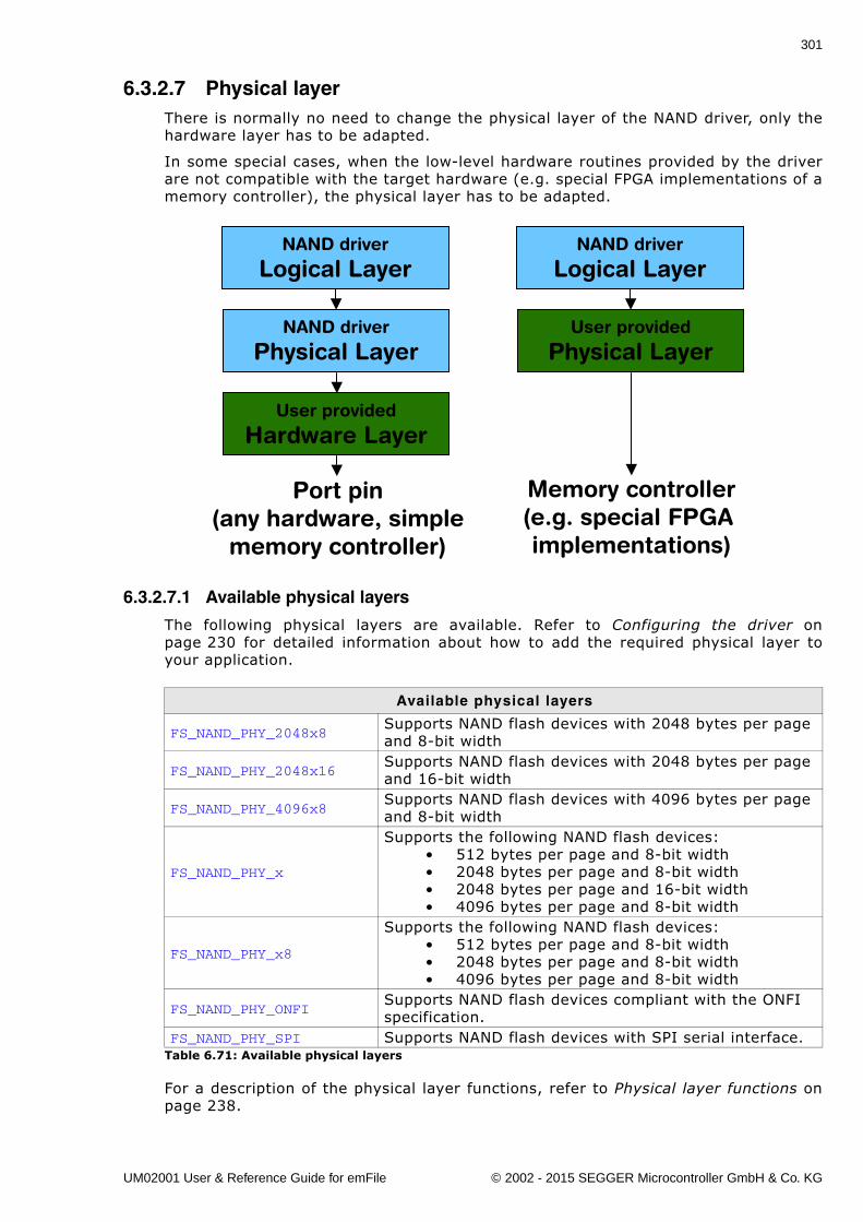
301
6.3.2.7 Physical layerThere is normally no need to change the physical layer of the NAND driver, only thehardware layer has to be adapted.
In some special cases, when the low-level hardware routines provided by the driverare not compatible with the target hardware (e.g. special FPGA implementations of amemory controller), the physical layer has to be adapted.
6.3.2.7.1 Available physical layers
The following physical layers are available. Refer to Configuring the driver onpage 230 for detailed information about how to add the required physical layer toyour application.
For a description of the physical layer functions, refer to Physical layer functions onpage 238.
Available physical layers
FS_NAND_PHY_2048x8Supports NAND flash devices with 2048 bytes per page and 8-bit width
FS_NAND_PHY_2048x16Supports NAND flash devices with 2048 bytes per page and 16-bit width
FS_NAND_PHY_4096x8Supports NAND flash devices with 4096 bytes per page and 8-bit width
FS_NAND_PHY_x
Supports the following NAND flash devices:� 512 bytes per page and 8-bit width� 2048 bytes per page and 8-bit width� 2048 bytes per page and 16-bit width� 4096 bytes per page and 8-bit width
FS_NAND_PHY_x8
Supports the following NAND flash devices:� 512 bytes per page and 8-bit width� 2048 bytes per page and 8-bit width� 4096 bytes per page and 8-bit width
FS_NAND_PHY_ONFISupports NAND flash devices compliant with the ONFI specification.
FS_NAND_PHY_SPI Supports NAND flash devices with SPI serial interface.Table 6.71: Available physical layers
NAND driver
Logical Layer
NAND driver
Physical Layer
User provided
Hardware Layer
NAND driver
Logical Layer
User provided
Physical Layer
Port pin(any hardware, simple
memory controller)
Memory controller(e.g. special FPGA implementations)
UM02001 User & Reference Guide for emFile © 2002 - 2015 SEGGER Microcontroller GmbH & Co. KG
302 CHAPTER 6 Device drivers
6.3.2.8 Hardware layerThe driver uses the same hardware layer as the SLC1 driver. For additional informa-tion, refer to Hardware functions - NAND flash on page 253.
UM02001 User & Reference Guide for emFile © 2002 - 2015 SEGGER Microcontroller GmbH & Co. KG
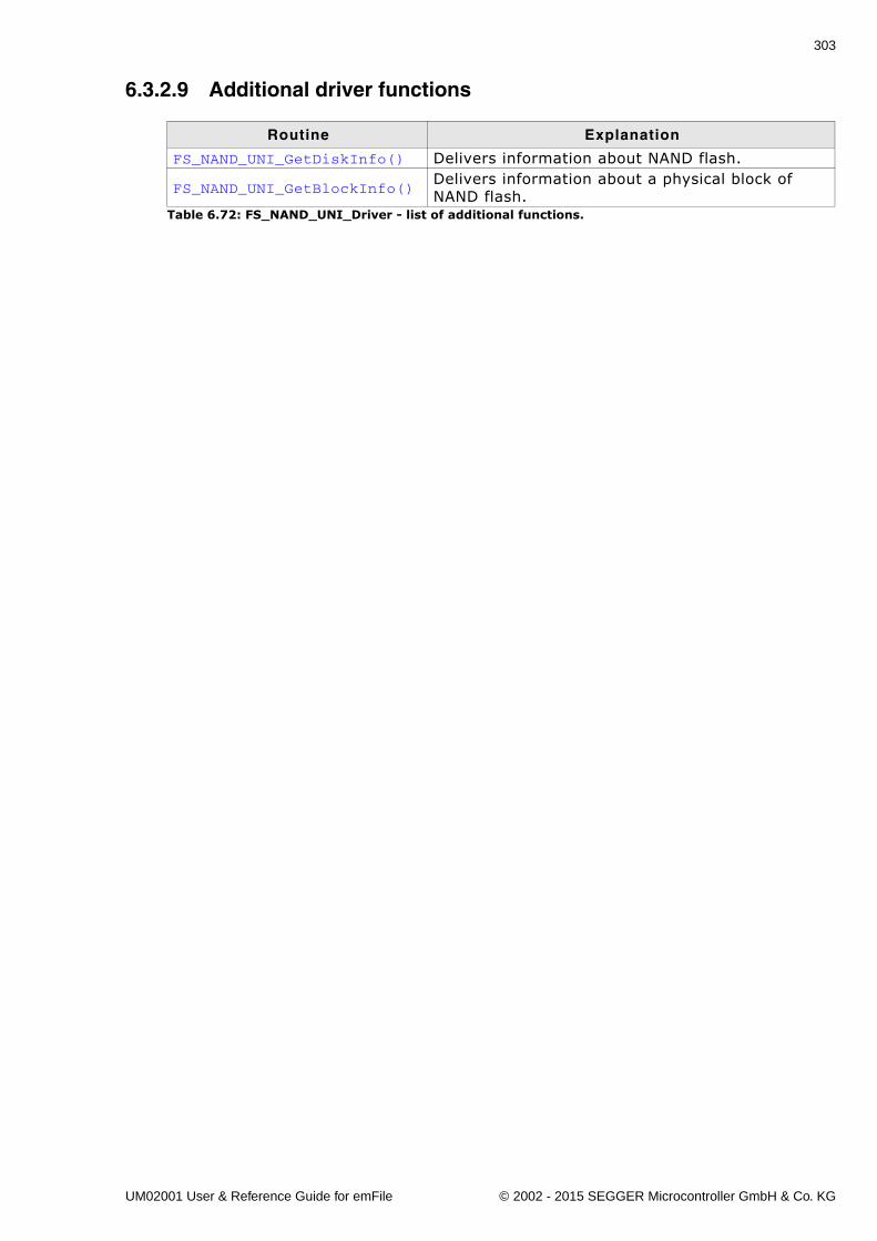
303
6.3.2.9 Additional driver functions
Routine Explanation
FS_NAND_UNI_GetDiskInfo() Delivers information about NAND flash.
FS_NAND_UNI_GetBlockInfo()Delivers information about a physical block of NAND flash.
Table 6.72: FS_NAND_UNI_Driver - list of additional functions.
UM02001 User & Reference Guide for emFile © 2002 - 2015 SEGGER Microcontroller GmbH & Co. KG
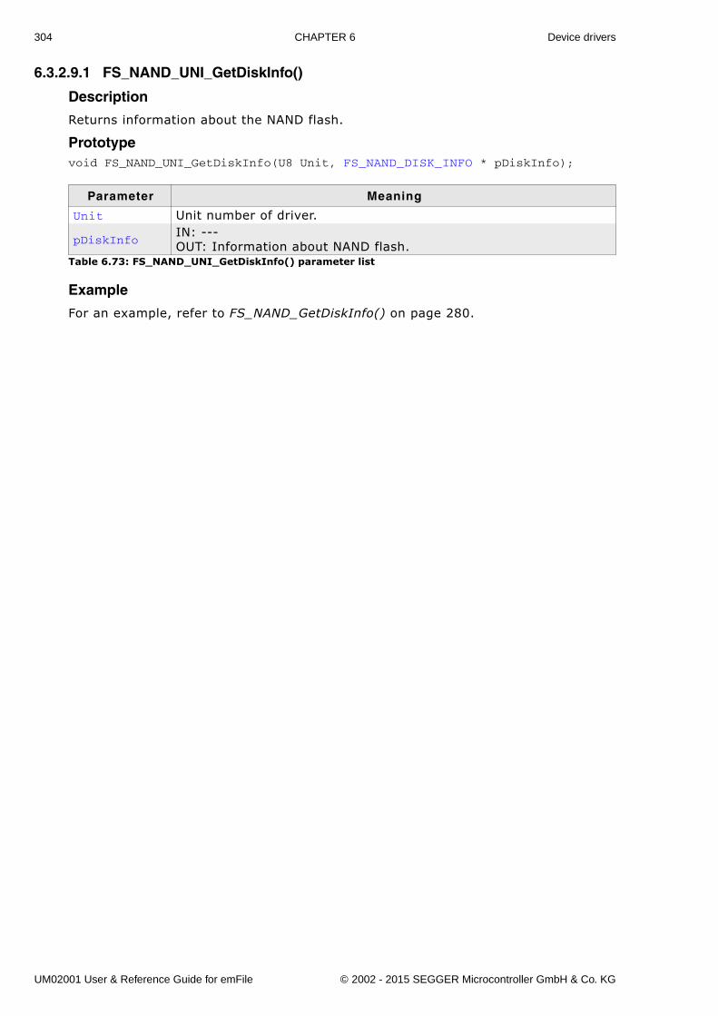
304 CHAPTER 6 Device drivers
6.3.2.9.1 FS_NAND_UNI_GetDiskInfo()
Description
Returns information about the NAND flash.
Prototypevoid FS_NAND_UNI_GetDiskInfo(U8 Unit, FS_NAND_DISK_INFO * pDiskInfo);
Example
For an example, refer to FS_NAND_GetDiskInfo() on page 280.
Parameter Meaning
Unit Unit number of driver.
pDiskInfoIN: ---OUT: Information about NAND flash.
Table 6.73: FS_NAND_UNI_GetDiskInfo() parameter list
UM02001 User & Reference Guide for emFile © 2002 - 2015 SEGGER Microcontroller GmbH & Co. KG
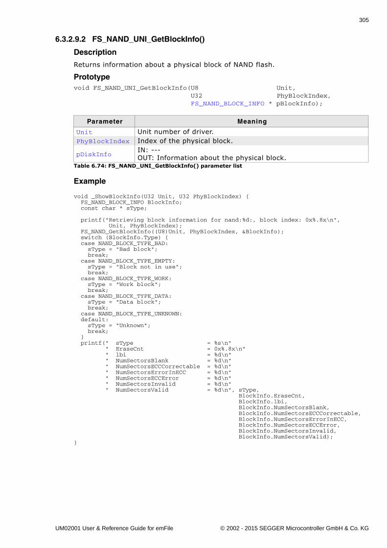
305
6.3.2.9.2 FS_NAND_UNI_GetBlockInfo()
Description
Returns information about a physical block of NAND flash.
Prototypevoid FS_NAND_UNI_GetBlockInfo(U8 Unit, U32 PhyBlockIndex, FS_NAND_BLOCK_INFO * pBlockInfo);
Example
void _ShowBlockInfo(U32 Unit, U32 PhyBlockIndex) { FS_NAND_BLOCK_INFO BlockInfo; const char * sType; printf("Retrieving block information for nand:%d:, block index: 0x%.8x\n", Unit, PhyBlockIndex); FS_NAND_GetBlockInfo((U8)Unit, PhyBlockIndex, &BlockInfo); switch (BlockInfo.Type) { case NAND_BLOCK_TYPE_BAD: sType = "Bad block"; break; case NAND_BLOCK_TYPE_EMPTY: sType = "Block not in use"; break; case NAND_BLOCK_TYPE_WORK: sType = "Work block"; break; case NAND_BLOCK_TYPE_DATA: sType = "Data block"; break; case NAND_BLOCK_TYPE_UNKNOWN: default: sType = "Unknown"; break; } printf(" sType = %s\n" " EraseCnt = 0x%.8x\n" " lbi = %d\n" " NumSectorsBlank = %d\n" " NumSectorsECCCorrectable = %d\n" " NumSectorsErrorInECC = %d\n" " NumSectorsECCError = %d\n" " NumSectorsInvalid = %d\n" " NumSectorsValid = %d\n", sType, BlockInfo.EraseCnt, BlockInfo.lbi, BlockInfo.NumSectorsBlank, BlockInfo.NumSectorsECCCorrectable, BlockInfo.NumSectorsErrorInECC, BlockInfo.NumSectorsECCError, BlockInfo.NumSectorsInvalid, BlockInfo.NumSectorsValid);}
Parameter Meaning
Unit Unit number of driver.PhyBlockIndex Index of the physical block.
pDiskInfoIN: ---OUT: Information about the physical block.
Table 6.74: FS_NAND_UNI_GetBlockInfo() parameter list
UM02001 User & Reference Guide for emFile © 2002 - 2015 SEGGER Microcontroller GmbH & Co. KG
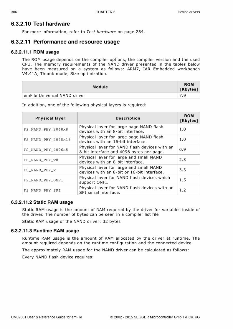
306 CHAPTER 6 Device drivers
6.3.2.10 Test hardwareFor more information, refer to Test hardware on page 284.
6.3.2.11 Performance and resource usage
6.3.2.11.1 ROM usage
The ROM usage depends on the compiler options, the compiler version and the usedCPU. The memory requirements of the NAND driver presented in the tables belowhave been measured on a system as follows: ARM7, IAR Embedded workbenchV4.41A, Thumb mode, Size optimization.
In addition, one of the following physical layers is required:
6.3.2.11.2 Static RAM usage
Static RAM usage is the amount of RAM required by the driver for variables inside ofthe driver. The number of bytes can be seen in a compiler list file
Static RAM usage of the NAND driver: 32 bytes
6.3.2.11.3 Runtime RAM usage
Runtime RAM usage is the amount of RAM allocated by the driver at runtime. Theamount required depends on the runtime configuration and the connected device.
The approximately RAM usage for the NAND driver can be calculated as follows:
Every NAND flash device requires:
ModuleROM
[Kbytes]
emFile Universal NAND driver 7.9
Physical layer DescriptionROM
[Kbytes]
FS_NAND_PHY_2048x8Physical layer for large page NAND flash devices with an 8-bit interface. 1.0
FS_NAND_PHY_2048x16Physical layer for large page NAND flash devices with an 16-bit interface. 1.0
FS_NAND_PHY_4096x8Physical layer for NAND flash devices with an 8-bit interface and 4096 bytes per page. 0.9
FS_NAND_PHY_x8Physical layer for large and small NAND devices with an 8-bit interface. 2.3
FS_NAND_PHY_xPhysical layer for large and small NAND devices with an 8-bit or 16-bit interface. 3.3
FS_NAND_PHY_ONFIPhysical layer for NAND flash devices which support ONFI. 1.5
FS_NAND_PHY_SPIPhysical layer for NAND flash devices with an SPI serial interface. 1.2
UM02001 User & Reference Guide for emFile © 2002 - 2015 SEGGER Microcontroller GmbH & Co. KG
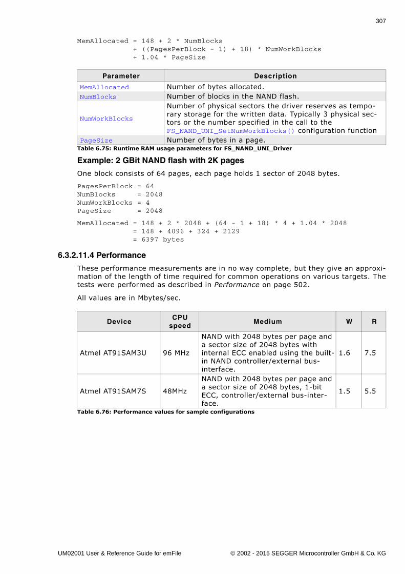
307
MemAllocated = 148 + 2 * NumBlocks + ((PagesPerBlock - 1) + 18) * NumWorkBlocks + 1.04 * PageSize
Example: 2 GBit NAND flash with 2K pages
One block consists of 64 pages, each page holds 1 sector of 2048 bytes.
PagesPerBlock = 64NumBlocks = 2048NumWorkBlocks = 4PageSize = 2048
MemAllocated = 148 + 2 * 2048 + (64 - 1 + 18) * 4 + 1.04 * 2048 = 148 + 4096 + 324 + 2129 = 6397 bytes
6.3.2.11.4 Performance
These performance measurements are in no way complete, but they give an approxi-mation of the length of time required for common operations on various targets. Thetests were performed as described in Performance on page 502.
All values are in Mbytes/sec.
Parameter Description
MemAllocated Number of bytes allocated.NumBlocks Number of blocks in the NAND flash.
NumWorkBlocks
Number of physical sectors the driver reserves as tempo-rary storage for the written data. Typically 3 physical sec-tors or the number specified in the call to the FS_NAND_UNI_SetNumWorkBlocks() configuration function
PageSize Number of bytes in a page.Table 6.75: Runtime RAM usage parameters for FS_NAND_UNI_Driver
DeviceCPU
speedMedium W R
Atmel AT91SAM3U 96 MHz
NAND with 2048 bytes per page and a sector size of 2048 bytes with internal ECC enabled using the built-in NAND controller/external bus-interface.
1.6 7.5
Atmel AT91SAM7S 48MHz
NAND with 2048 bytes per page and a sector size of 2048 bytes, 1-bit ECC, controller/external bus-inter-face.
1.5 5.5
Table 6.76: Performance values for sample configurations
UM02001 User & Reference Guide for emFile © 2002 - 2015 SEGGER Microcontroller GmbH & Co. KG
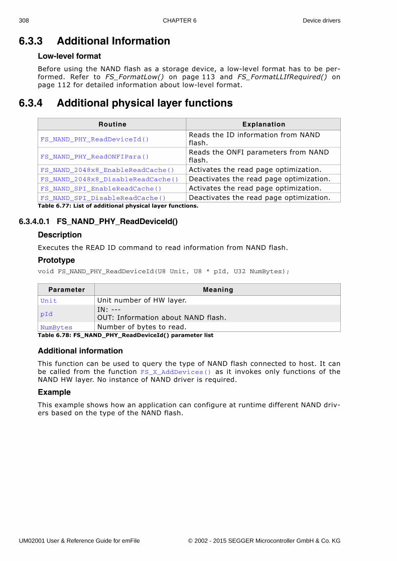
308 CHAPTER 6 Device drivers
6.3.3 Additional InformationLow-level format
Before using the NAND flash as a storage device, a low-level format has to be per-formed. Refer to FS_FormatLow() on page 113 and FS_FormatLLIfRequired() onpage 112 for detailed information about low-level format.
6.3.4 Additional physical layer functions
6.3.4.0.1 FS_NAND_PHY_ReadDeviceId()
Description
Executes the READ ID command to read information from NAND flash.
Prototypevoid FS_NAND_PHY_ReadDeviceId(U8 Unit, U8 * pId, U32 NumBytes);
Additional information
This function can be used to query the type of NAND flash connected to host. It canbe called from the function FS_X_AddDevices() as it invokes only functions of theNAND HW layer. No instance of NAND driver is required.
Example
This example shows how an application can configure at runtime different NAND driv-ers based on the type of the NAND flash.
Routine Explanation
FS_NAND_PHY_ReadDeviceId()Reads the ID information from NAND flash.
FS_NAND_PHY_ReadONFIPara()Reads the ONFI parameters from NAND flash.
FS_NAND_2048x8_EnableReadCache() Activates the read page optimization.FS_NAND_2048x8_DisableReadCache() Deactivates the read page optimization.FS_NAND_SPI_EnableReadCache() Activates the read page optimization.FS_NAND_SPI_DisableReadCache() Deactivates the read page optimization.
Table 6.77: List of additional physical layer functions.
Parameter Meaning
Unit Unit number of HW layer.
pIdIN: ---OUT: Information about NAND flash.
NumBytes Number of bytes to read.Table 6.78: FS_NAND_PHY_ReadDeviceId() parameter list
UM02001 User & Reference Guide for emFile © 2002 - 2015 SEGGER Microcontroller GmbH & Co. KG
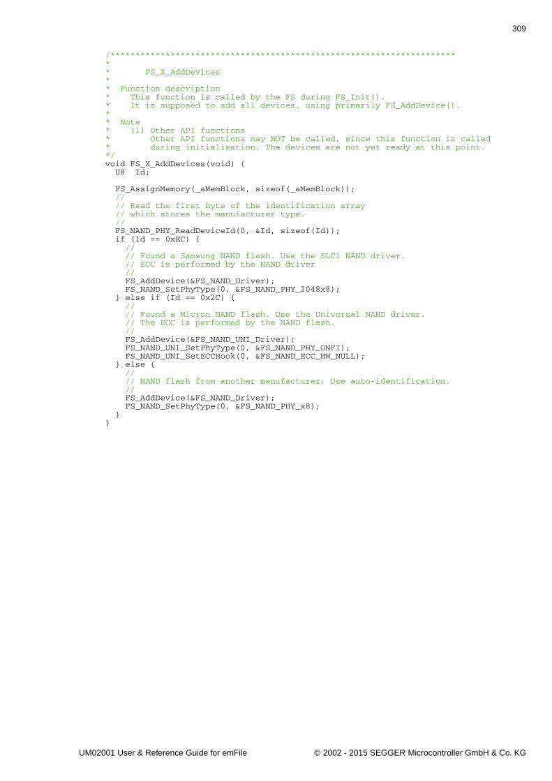
309
/*********************************************************************** FS_X_AddDevices** Function description* This function is called by the FS during FS_Init().* It is supposed to add all devices, using primarily FS_AddDevice().** Note* (1) Other API functions* Other API functions may NOT be called, since this function is called* during initialisation. The devices are not yet ready at this point.*/void FS_X_AddDevices(void) { U8 Id;
FS_AssignMemory(_aMemBlock, sizeof(_aMemBlock)); // // Read the first byte of the identification array // which stores the manufacturer type. // FS_NAND_PHY_ReadDeviceId(0, &Id, sizeof(Id)); if (Id == 0xEC) { // // Found a Samsung NAND flash. Use the SLC1 NAND driver. // ECC is performed by the NAND driver // FS_AddDevice(&FS_NAND_Driver); FS_NAND_SetPhyType(0, &FS_NAND_PHY_2048x8); } else if (Id == 0x2C) { // // Found a Micron NAND flash. Use the Universal NAND driver. // The ECC is performed by the NAND flash. // FS_AddDevice(&FS_NAND_UNI_Driver); FS_NAND_UNI_SetPhyType(0, &FS_NAND_PHY_ONFI); FS_NAND_UNI_SetECCHook(0, &FS_NAND_ECC_HW_NULL); } else { // // NAND flash from another manufacturer, Use auto-identification. // FS_AddDevice(&FS_NAND_Driver); FS_NAND_SetPhyType(0, &FS_NAND_PHY_x8); }}
UM02001 User & Reference Guide for emFile © 2002 - 2015 SEGGER Microcontroller GmbH & Co. KG
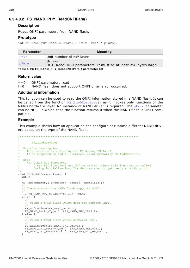
310 CHAPTER 6 Device drivers
6.3.4.0.2 FS_NAND_PHY_ReadONFIPara()
Description
Reads ONFI parameters from NAND flash.
Prototypeint FS_NAND_PHY_ReadONFIPara(U8 Unit, void * pPara);
Return value
==0 ONFI parameters read.!=0 NAND flash does not support ONFI or an error occurred.
Additional information
This function can be used to read the ONFI information stored in a NAND flash. It canbe called from the function FS_X_AddDevices() as it invokes only functions of theNAND hardware layer. No instance of NAND driver is required. The pPara parametercan be NULL in which case the function returns 0 when the NAND flash is ONFI com-patible.
Example
This example shows how an application can configure at runtime different NAND driv-ers based on the type of the NAND flash.
/*********************************************************************** FS_X_AddDevices** Function description* This function is called by the FS during FS_Init().* It is supposed to add all devices, using primarily FS_AddDevice().** Note* (1) Other API functions* Other API functions may NOT be called, since this function is called* during initialisation. The devices are not yet ready at this point.*/void FS_X_AddDevices(void) { int r;
FS_AssignMemory(_aMemBlock, sizeof(_aMemBlock)); // // Check whether the NAND flash supports ONFI. // r = FS_NAND_PHY_ReadONFIPara(0, NULL); if (r) { // // Found a NAND flash which does not support ONFI. // FS_AddDevice(&FS_NAND_Driver); FS_NAND_SetPhyType(0, &FS_NAND_PHY_2048x8); } else { // // Found a NAND flash which supports ONFI. // FS_AddDevice(&FS_NAND_UNI_Driver); FS_NAND_UNI_SetPhyType(0, &FS_NAND_PHY_ONFI); FS_NAND_UNI_SetECCHook(0, &FS_NAND_ECC_HW_NULL); }}
Parameter Meaning
Unit Unit number of HW layer.
pParaIN: ---OUT: Read ONFI parameters. It must be at least 256 bytes large.
Table 6.79: FS_NAND_PHY_ReadONFIPara() parameter list
UM02001 User & Reference Guide for emFile © 2002 - 2015 SEGGER Microcontroller GmbH & Co. KG
311
6.3.4.0.3 FS_NAND_2048x8_EnableReadCache()
Description
Activates the read page optimization.
Prototypevoid FS_NAND_2048x8_EnableReadCache(U8 Unit);
Additional information
A page read operation consists of 2 steps. On the first step the page data is readfrom memory array to internal page register of NAND flash device. On the secondstep the data is transferred from internal page register of NAND flash device to hostCPU. With the optimization enabled the first step is skipped when possible.
The optimization is enabled by default and should be disabled if 2 or more instancesof NAND driver are configured to access the same NAND flash device.
Parameter Meaning
Unit Unit number of physical layer.Table 6.80: FS_NAND_2048x8_EnableReadCache() parameter list
UM02001 User & Reference Guide for emFile © 2002 - 2015 SEGGER Microcontroller GmbH & Co. KG
312 CHAPTER 6 Device drivers
6.3.4.0.4 FS_NAND_2048x8_DisableReadCache()
Description
Deactivates the read page optimization.
Prototypevoid FS_NAND_2048x8_DisableReadCache(U8 Unit);
Additional information
For additional information, refer to FS_NAND_2048x8_EnableReadCache() onpage 311.
Parameter Meaning
Unit Unit number of physical layer.Table 6.81: FS_NAND_2048x8_DisableReadCache() parameter list
UM02001 User & Reference Guide for emFile © 2002 - 2015 SEGGER Microcontroller GmbH & Co. KG
313
6.3.4.0.5 FS_NAND_SPI_EnableReadCache()
Description
Activates the read page optimization of the FS_NAND_PHY_SPI physical layer.
Prototypevoid FS_NAND_SPI_EnableReadCache(U8 Unit);
Additional information
For additional information, refer to FS_NAND_2048x8_EnableReadCache() onpage 311.
Parameter Meaning
Unit Unit number of physical layer.Table 6.82: FS_NAND_SPI_EnableReadCache() parameter list
UM02001 User & Reference Guide for emFile © 2002 - 2015 SEGGER Microcontroller GmbH & Co. KG
314 CHAPTER 6 Device drivers
6.3.4.0.6 FS_NAND_SPI_DisableReadCache()
Description
Deactivates the read page optimization of the FS_NAND_PHY_SPI physical layer.
Prototypevoid FS_NAND_SPI_DisableReadCache(U8 Unit);
Additional information
For additional information, refer to FS_NAND_2048x8_EnableReadCache() onpage 311.
Parameter Meaning
Unit Unit number of physical layer.Table 6.83: FS_NAND_SPI_DisableReadCache() parameter list
UM02001 User & Reference Guide for emFile © 2002 - 2015 SEGGER Microcontroller GmbH & Co. KG
315
6.4 NOR flash driveremFile supports the use of NOR flashes. Two optional drivers for NOR flashes areavailable:
� Sector map driver - optimized for read/write speed.� Block map driver - optimized for reduced RAM usage.
They can work with almost any NOR flash and are extremely efficient. The differencebetween the drivers consists in the way they are managing the mapping of file sys-tem sectors to NOR flash storage.
The Sector map driver was designed with the goal to access the data fast at a timewhen the NOR flashes had a relatively small capacity. To achieve this, the drivermaintains a mapping table at sector granularity. This approach has been proven to beefficient, but modern NOR flashes with capacities over 1MB the RAM usage of thedriver increases. This is the reason why the Block map driver was developed.
The design goal of the Block map driver was to use as few RAM as possible. Thedriver maps blocks of file system sectors to NOR storage. In this way the RAMrequirements of the driver are kept to a minimum.
6.4.1 Sector map driver - FS_NOR_DriverThis section describes the NOR driver which is optimized for fast write speed. Itworks by mapping single logical sectors to locations on the NOR flash memory.
6.4.1.1 Supported hardwareThe NOR flash drivers can be used with almost any NOR flash. This includes NORflashes with 1x8-bit and 1x16-bit parallel interfaces, as well as 2x16-bit interfaces inparallel, as well as serial NOR flashes.
Requirements
To be more precise, any NOR flash which fulfills the following requirements:
� Minimum of 2 physical sectors. At least 2 sectors need to be identical in size.� Physical sectors need to be at least 2048 bytes each.� Physical sectors do not need to be uniform
(for example, 8 * 8 Kbytes + 3 * 64 Kbytes is permitted).� Flash needs to be re-writable without erase: The same location can be written to
multiple times without erase, as long as only 1-bits are converted to 0-bits.� Erase clears all bits in a physical sector to 1.
Physical layer
The driver requires a physical layer for the flash device.
The following physical layers are available:
� FS_NOR_PHY_CFI_1x16 - CFI compliant parallel NOR flash with 1x16-bit inter-face
� FS_NOR_PHY_CFI_2x16 - CFI compliant parallel NOR flash with 2x16-bit inter-face
� FS_NOR_PHY_ST_M25 - Serial flash (ST M25Pxx family)� FS_NOR_PHY_SFDP - Serial flash compliant with the JEDEC JESD216 standard.� Physical layer template
Common flash interface (CFI)
The NOR flash drivers can be used with any CFI-compliant 16-bit chip. The CommonFlash Memory Interface (CFI) is an open specification which may be implementedfreely by flash memory vendors in their devices. It was developed jointly by Intel,AMD, Sharp, and Fujitsu.
UM02001 User & Reference Guide for emFile © 2002 - 2015 SEGGER Microcontroller GmbH & Co. KG
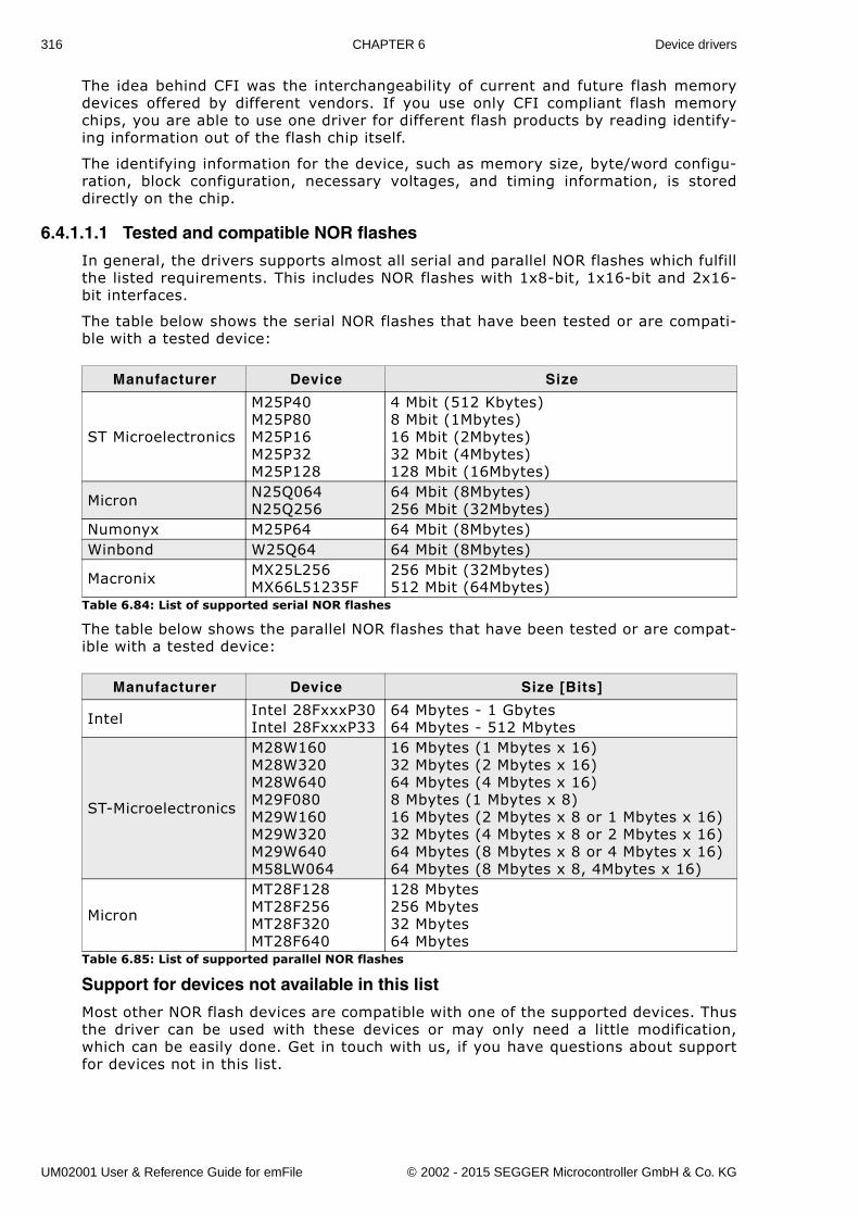
316 CHAPTER 6 Device drivers
The idea behind CFI was the interchangeability of current and future flash memorydevices offered by different vendors. If you use only CFI compliant flash memorychips, you are able to use one driver for different flash products by reading identify-ing information out of the flash chip itself.
The identifying information for the device, such as memory size, byte/word configu-ration, block configuration, necessary voltages, and timing information, is storeddirectly on the chip.
6.4.1.1.1 Tested and compatible NOR flashes
In general, the drivers supports almost all serial and parallel NOR flashes which fulfillthe listed requirements. This includes NOR flashes with 1x8-bit, 1x16-bit and 2x16-bit interfaces.
The table below shows the serial NOR flashes that have been tested or are compati-ble with a tested device:
The table below shows the parallel NOR flashes that have been tested or are compat-ible with a tested device:
Support for devices not available in this list
Most other NOR flash devices are compatible with one of the supported devices. Thusthe driver can be used with these devices or may only need a little modification,which can be easily done. Get in touch with us, if you have questions about supportfor devices not in this list.
Manufacturer Device Size
ST Microelectronics
M25P40M25P80M25P16M25P32M25P128
4 Mbit (512 Kbytes) 8 Mbit (1Mbytes)16 Mbit (2Mbytes)32 Mbit (4Mbytes)128 Mbit (16Mbytes)
Micron N25Q064N25Q256
64 Mbit (8Mbytes)256 Mbit (32Mbytes)
Numonyx M25P64 64 Mbit (8Mbytes)Winbond W25Q64 64 Mbit (8Mbytes)
Macronix MX25L256MX66L51235F
256 Mbit (32Mbytes)512 Mbit (64Mbytes)
Table 6.84: List of supported serial NOR flashes
Manufacturer Device Size [Bits]
Intel Intel 28FxxxP30Intel 28FxxxP33
64 Mbytes - 1 Gbytes64 Mbytes - 512 Mbytes
ST-Microelectronics
M28W160M28W320M28W640M29F080M29W160M29W320M29W640M58LW064
16 Mbytes (1 Mbytes x 16)32 Mbytes (2 Mbytes x 16)64 Mbytes (4 Mbytes x 16)8 Mbytes (1 Mbytes x 8)16 Mbytes (2 Mbytes x 8 or 1 Mbytes x 16)32 Mbytes (4 Mbytes x 8 or 2 Mbytes x 16)64 Mbytes (8 Mbytes x 8 or 4 Mbytes x 16)64 Mbytes (8 Mbytes x 8, 4Mbytes x 16)
Micron
MT28F128MT28F256MT28F320MT28F640
128 Mbytes256 Mbytes32 Mbytes64 Mbytes
Table 6.85: List of supported parallel NOR flashes
UM02001 User & Reference Guide for emFile © 2002 - 2015 SEGGER Microcontroller GmbH & Co. KG
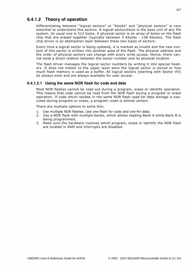
317
6.4.1.2 Theory of operationDifferentiating between �logical sectors� or �blocks� and �physical sectors� is veryessential to understand this section. A logical sector/block is the base unit of any filesystem, its usual size is 512 bytes. A physical sector is an array of bytes on the flashchip that are erased together (typically between 2 Kbytes - 128 Kbytes). The flashchip driver is an abstraction layer between these two types of sectors.
Every time a logical sector is being updated, it is marked as invalid and the new con-tent of this sector is written into another area of the flash. The physical address andthe order of physical sectors can change with every write access. Hence, there can-not exist a direct relation between the sector number and its physical location.
The flash driver manages the logical sector numbers by writing it into special head-ers. It does not matter to the upper layer were the logical sector is stored or howmuch flash memory is used as a buffer. All logical sectors (starting with Sector #0)do always exist and are always available for user access.
6.4.1.2.1 Using the same NOR flash for code and data
Most NOR flashes cannot be read out during a program, erase or identify operation.This means that code cannot be read from the NOR flash during a program or eraseoperation. If code which resides in the same NOR flash used for data storage is exe-cuted during program or erase, a program crash is almost certain.
There are multiple options to solve this:
1. Use multiple NOR flashes. Use one flash for code and one for data.2. Use a NOR flash with multiple banks, which allows reading Bank A while Bank B is
being programmed.3. Make sure the hardware routines which program, erase or identify the NOR flash
are located in RAM and interrupts are disabled.
UM02001 User & Reference Guide for emFile © 2002 - 2015 SEGGER Microcontroller GmbH & Co. KG
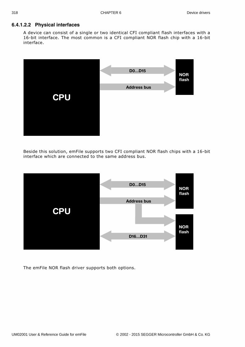
318 CHAPTER 6 Device drivers
6.4.1.2.2 Physical interfaces
A device can consist of a single or two identical CFI compliant flash interfaces with a16-bit interface. The most common is a CFI compliant NOR flash chip with a 16-bitinterface.
Beside this solution, emFile supports two CFI compliant NOR flash chips with a 16-bitinterface which are connected to the same address bus.
The emFile NOR flash driver supports both options.
D0...D15
Address bus
NORflash
CPU
D0...D15
D16...D31
Address bus
NORflash
NORflash
CPU
UM02001 User & Reference Guide for emFile © 2002 - 2015 SEGGER Microcontroller GmbH & Co. KG
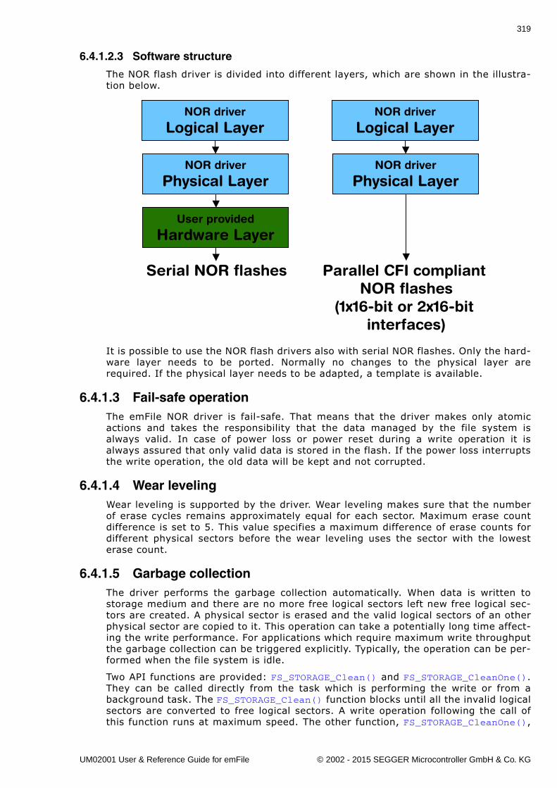
319
6.4.1.2.3 Software structure
The NOR flash driver is divided into different layers, which are shown in the illustra-tion below.
It is possible to use the NOR flash drivers also with serial NOR flashes. Only the hard-ware layer needs to be ported. Normally no changes to the physical layer arerequired. If the physical layer needs to be adapted, a template is available.
6.4.1.3 Fail-safe operationThe emFile NOR driver is fail-safe. That means that the driver makes only atomicactions and takes the responsibility that the data managed by the file system isalways valid. In case of power loss or power reset during a write operation it isalways assured that only valid data is stored in the flash. If the power loss interruptsthe write operation, the old data will be kept and not corrupted.
6.4.1.4 Wear levelingWear leveling is supported by the driver. Wear leveling makes sure that the numberof erase cycles remains approximately equal for each sector. Maximum erase countdifference is set to 5. This value specifies a maximum difference of erase counts fordifferent physical sectors before the wear leveling uses the sector with the lowesterase count.
6.4.1.5 Garbage collectionThe driver performs the garbage collection automatically. When data is written tostorage medium and there are no more free logical sectors left new free logical sec-tors are created. A physical sector is erased and the valid logical sectors of an otherphysical sector are copied to it. This operation can take a potentially long time affect-ing the write performance. For applications which require maximum write throughputthe garbage collection can be triggered explicitly. Typically, the operation can be per-formed when the file system is idle.
Two API functions are provided: FS_STORAGE_Clean() and FS_STORAGE_CleanOne().They can be called directly from the task which is performing the write or from abackground task. The FS_STORAGE_Clean() function blocks until all the invalid logicalsectors are converted to free logical sectors. A write operation following the call ofthis function runs at maximum speed. The other function, FS_STORAGE_CleanOne(),
NOR driver
Logical Layer
NOR driver
Physical Layer
User provided
Hardware Layer
NOR driver
Logical Layer
NOR driver
Physical Layer
Serial NOR flashes Parallel CFI compliantNOR flashes
(1x16-bit or 2x16-bit interfaces)
UM02001 User & Reference Guide for emFile © 2002 - 2015 SEGGER Microcontroller GmbH & Co. KG
320 CHAPTER 6 Device drivers
converts the invalid sectors of a single physical sector. Depending on the number ofinvalid logical sectors, several calls to this function are required to clean up the wholestorage medium.
UM02001 User & Reference Guide for emFile © 2002 - 2015 SEGGER Microcontroller GmbH & Co. KG
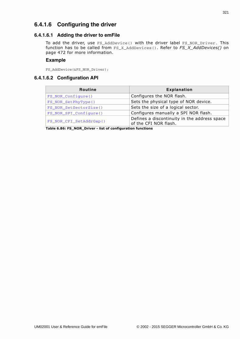
321
6.4.1.6 Configuring the driver
6.4.1.6.1 Adding the driver to emFile
To add the driver, use FS_AddDevice() with the driver label FS_NOR_Driver. Thisfunction has to be called from FS_X_AddDevices(). Refer to FS_X_AddDevices() onpage 472 for more information.
Example
FS_AddDevice(&FS_NOR_Driver);
6.4.1.6.2 Configuration API
Routine Explanation
FS_NOR_Configure() Configures the NOR flash.FS_NOR_SetPhyType() Sets the physical type of NOR device.FS_NOR_SetSectorSize() Sets the size of a logical sector.FS_NOR_SPI_Configure() Configures manually a SPI NOR flash.
FS_NOR_CFI_SetAddrGap()Defines a discontinuity in the address space of the CFI NOR flash.
Table 6.86: FS_NOR_Driver - list of configuration functions
UM02001 User & Reference Guide for emFile © 2002 - 2015 SEGGER Microcontroller GmbH & Co. KG
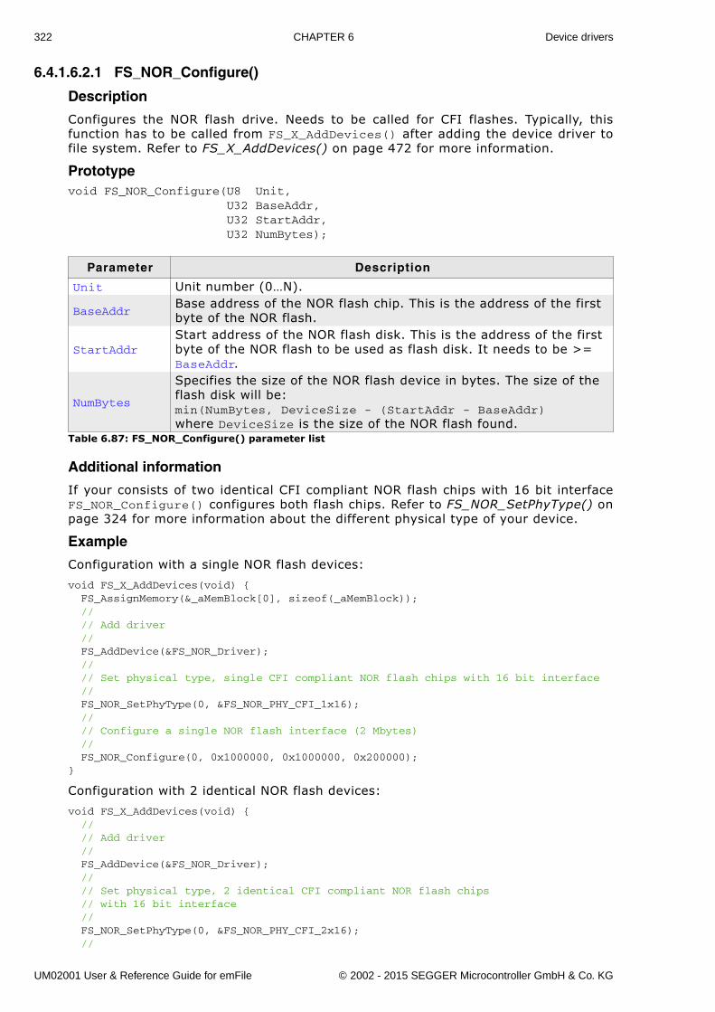
322 CHAPTER 6 Device drivers
6.4.1.6.2.1 FS_NOR_Configure()
Description
Configures the NOR flash drive. Needs to be called for CFI flashes. Typically, thisfunction has to be called from FS_X_AddDevices() after adding the device driver tofile system. Refer to FS_X_AddDevices() on page 472 for more information.
Prototypevoid FS_NOR_Configure(U8 Unit, U32 BaseAddr, U32 StartAddr, U32 NumBytes);
Additional information
If your consists of two identical CFI compliant NOR flash chips with 16 bit interfaceFS_NOR_Configure() configures both flash chips. Refer to FS_NOR_SetPhyType() onpage 324 for more information about the different physical type of your device.
Example
Configuration with a single NOR flash devices:
void FS_X_AddDevices(void) { FS_AssignMemory(&_aMemBlock[0], sizeof(_aMemBlock)); // // Add driver // FS_AddDevice(&FS_NOR_Driver); // // Set physical type, single CFI compliant NOR flash chips with 16 bit interface // FS_NOR_SetPhyType(0, &FS_NOR_PHY_CFI_1x16); // // Configure a single NOR flash interface (2 Mbytes) // FS_NOR_Configure(0, 0x1000000, 0x1000000, 0x200000);}
Configuration with 2 identical NOR flash devices:
void FS_X_AddDevices(void) { // // Add driver // FS_AddDevice(&FS_NOR_Driver); // // Set physical type, 2 identical CFI compliant NOR flash chips // with 16 bit interface // FS_NOR_SetPhyType(0, &FS_NOR_PHY_CFI_2x16); //
Parameter Description
Unit Unit number (0�N).
BaseAddrBase address of the NOR flash chip. This is the address of the first byte of the NOR flash.
StartAddrStart address of the NOR flash disk. This is the address of the first byte of the NOR flash to be used as flash disk. It needs to be >= BaseAddr.
NumBytes
Specifies the size of the NOR flash device in bytes. The size of the flash disk will be: min(NumBytes, DeviceSize - (StartAddr - BaseAddr) where DeviceSize is the size of the NOR flash found.
Table 6.87: FS_NOR_Configure() parameter list
UM02001 User & Reference Guide for emFile © 2002 - 2015 SEGGER Microcontroller GmbH & Co. KG
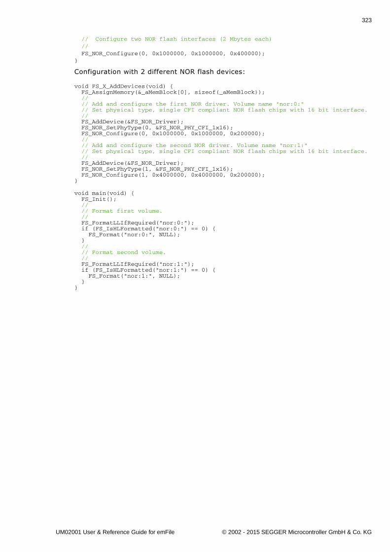
323
// Configure two NOR flash interfaces (2 Mbytes each) // FS_NOR_Configure(0, 0x1000000, 0x1000000, 0x400000);}
Configuration with 2 different NOR flash devices:
void FS_X_AddDevices(void) { FS_AssignMemory(&_aMemBlock[0], sizeof(_aMemBlock)); // // Add and configure the first NOR driver. Volume name "nor:0:" // Set physical type, single CFI compliant NOR flash chips with 16 bit interface. // FS_AddDevice(&FS_NOR_Driver); FS_NOR_SetPhyType(0, &FS_NOR_PHY_CFI_1x16); FS_NOR_Configure(0, 0x1000000, 0x1000000, 0x200000); // // Add and configure the second NOR driver. Volume name "nor:1:" // Set physical type, single CFI compliant NOR flash chips with 16 bit interface. // FS_AddDevice(&FS_NOR_Driver); FS_NOR_SetPhyType(1, &FS_NOR_PHY_CFI_1x16); FS_NOR_Configure(1, 0x4000000, 0x4000000, 0x200000);}
void main(void) { FS_Init(); // // Format first volume. // FS_FormatLLIfRequired("nor:0:"); if (FS_IsHLFormatted("nor:0:") == 0) { FS_Format("nor:0:", NULL); } // // Format second volume. // FS_FormatLLIfRequired("nor:1:"); if (FS_IsHLFormatted("nor:1:") == 0) { FS_Format("nor:1:", NULL); }}
UM02001 User & Reference Guide for emFile © 2002 - 2015 SEGGER Microcontroller GmbH & Co. KG
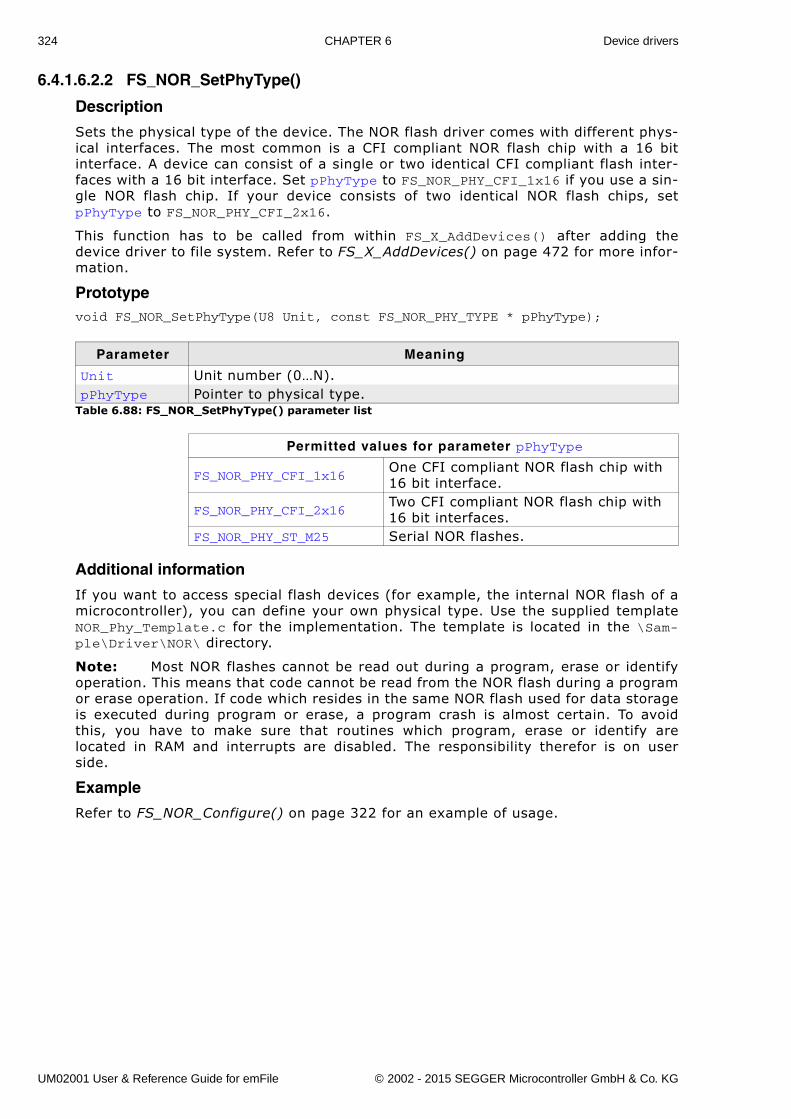
324 CHAPTER 6 Device drivers
6.4.1.6.2.2 FS_NOR_SetPhyType()
Description
Sets the physical type of the device. The NOR flash driver comes with different phys-ical interfaces. The most common is a CFI compliant NOR flash chip with a 16 bitinterface. A device can consist of a single or two identical CFI compliant flash inter-faces with a 16 bit interface. Set pPhyType to FS_NOR_PHY_CFI_1x16 if you use a sin-gle NOR flash chip. If your device consists of two identical NOR flash chips, setpPhyType to FS_NOR_PHY_CFI_2x16.
This function has to be called from within FS_X_AddDevices() after adding thedevice driver to file system. Refer to FS_X_AddDevices() on page 472 for more infor-mation.
Prototypevoid FS_NOR_SetPhyType(U8 Unit, const FS_NOR_PHY_TYPE * pPhyType);
Additional information
If you want to access special flash devices (for example, the internal NOR flash of amicrocontroller), you can define your own physical type. Use the supplied templateNOR_Phy_Template.c for the implementation. The template is located in the \Sam-ple\Driver\NOR\ directory.
Note: Most NOR flashes cannot be read out during a program, erase or identifyoperation. This means that code cannot be read from the NOR flash during a programor erase operation. If code which resides in the same NOR flash used for data storageis executed during program or erase, a program crash is almost certain. To avoidthis, you have to make sure that routines which program, erase or identify arelocated in RAM and interrupts are disabled. The responsibility therefor is on userside.
Example
Refer to FS_NOR_Configure() on page 322 for an example of usage.
Parameter Meaning
Unit Unit number (0�N).pPhyType Pointer to physical type.
Table 6.88: FS_NOR_SetPhyType() parameter list
Permitted values for parameter pPhyType
FS_NOR_PHY_CFI_1x16One CFI compliant NOR flash chip with 16 bit interface.
FS_NOR_PHY_CFI_2x16Two CFI compliant NOR flash chip with 16 bit interfaces.
FS_NOR_PHY_ST_M25 Serial NOR flashes.
UM02001 User & Reference Guide for emFile © 2002 - 2015 SEGGER Microcontroller GmbH & Co. KG
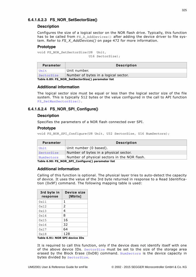
325
6.4.1.6.2.3 FS_NOR_SetSectorSize()
Description
Configures the size of a logical sector on the NOR flash drive. Typically, this functionhas to be called from FS_X_AddDevices() after adding the device driver to file sys-tem. Refer to FS_X_AddDevices() on page 472 for more information.
Prototypevoid FS_NOR_SetSectorSize(U8 Unit, U16 SectorSize);
Additional information
The logical sector size must be equal or less than the logical sector size of the filesystem. This is typically 512 bytes or the value configured in the call to API functionFS_SetMaxSectorSize().
6.4.1.6.2.4 FS_NOR_SPI_Configure()
Description
Specifies the parameters of a NOR flash connected over SPI.
Prototypevoid FS_NOR_SPI_Configure(U8 Unit, U32 SectorSize, U16 NumSectors);
Additional information
Calling of this function is optional. The physical layer tries to auto-detect the capacityof device. It uses the value of the 3rd byte returned in response to a Read Identifica-tion (0x9F) command. The following mapping table is used:
It is required to call this function, only if the device does not identify itself with oneof the above device IDs. SectorSize must be set to the size of the storage areaerased by the Block Erase (0xD8) command. NumSectors is the device capacity inbytes divided by SectorSize.
Parameter Description
Unit Unit number.SectorSize Number of bytes in a logical sector.
Table 6.89: FS_NOR_SetSectorSize() parameter list
Parameter Description
Unit Unit number (0 based).SectorSize Number of bytes in a physical sector.NumSectors Number of physical sectors in the NOR flash.
Table 6.90: FS_NOR_SPI_Configure() parameter list
3rd byte in response
Device size[Mbits]
0x11 10x12 20x13 40x14 80x15 160x16 320x17 640x18 128
Table 6.91: NOR SPI device IDs
UM02001 User & Reference Guide for emFile © 2002 - 2015 SEGGER Microcontroller GmbH & Co. KG
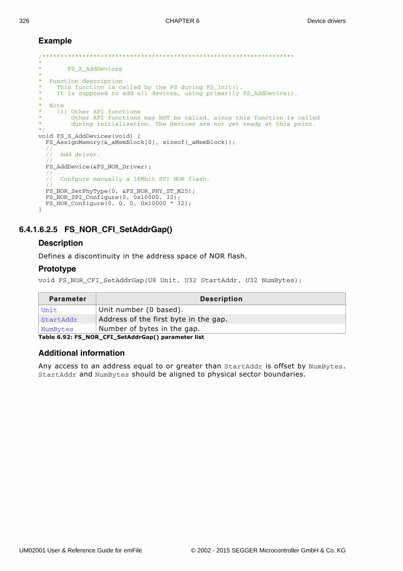
326 CHAPTER 6 Device drivers
Example
/*********************************************************************** FS_X_AddDevices** Function description* This function is called by the FS during FS_Init().* It is supposed to add all devices, using primarily FS_AddDevice().** Note* (1) Other API functions* Other API functions may NOT be called, since this function is called* during initialisation. The devices are not yet ready at this point.*/void FS_X_AddDevices(void) { FS_AssignMemory(&_aMemBlock[0], sizeof(_aMemBlock)); // // Add driver. // FS_AddDevice(&FS_NOR_Driver); // // Confgure manually a 16Mbit SPI NOR flash. // FS_NOR_SetPhyType(0, &FS_NOR_PHY_ST_M25); FS_NOR_SPI_Configure(0, 0x10000, 32); FS_NOR_Configure(0, 0, 0, 0x10000 * 32);}
6.4.1.6.2.5 FS_NOR_CFI_SetAddrGap()
Description
Defines a discontinuity in the address space of NOR flash.
Prototypevoid FS_NOR_CFI_SetAddrGap(U8 Unit, U32 StartAddr, U32 NumBytes);
Additional information
Any access to an address equal to or greater than StartAddr is offset by NumBytes.StartAddr and NumBytes should be aligned to physical sector boundaries.
Parameter Description
Unit Unit number (0 based).StartAddr Address of the first byte in the gap.NumBytes Number of bytes in the gap.
Table 6.92: FS_NOR_CFI_SetAddrGap() parameter list
UM02001 User & Reference Guide for emFile © 2002 - 2015 SEGGER Microcontroller GmbH & Co. KG
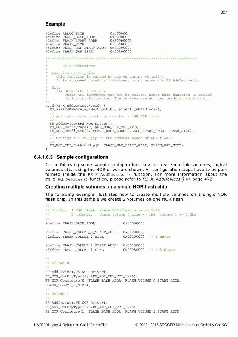
327
Example
#define ALLOC_SIZE 0x400000#define FLASH_BASE_ADDR 0x80000000#define FLASH_START_ADDR 0x80000000#define FLASH_SIZE 0x00400000#define FLASH_GAP_START_ADDR 0x80200000#define FLASH_GAP_SIZE 0x00200000
/*********************************************************************** FS_X_AddDevices** Function description* This function is called by the FS during FS_Init().* It is supposed to add all devices, using primarily FS_AddDevice().** Note* (1) Other API functions* Other API functions may NOT be called, since this function is called* during initialisation. The devices are not yet ready at this point.*/void FS_X_AddDevices(void) { FS_AssignMemory(&_aMemBlock[0], sizeof(_aMemBlock)); // // Add and configure the driver for a 4MB NOR flash. // FS_AddDevice(&FS_NOR_Driver); FS_NOR_SetPhyType(0, &FS_NOR_PHY_CFI_1x16); FS_NOR_Configure(0, FLASH_BASE_ADDR, FLASH_START_ADDR, FLASH_SIZE); // // Configure a 2MB gap in the address space of NOR flash. // FS_NOR_CFI_SetAddrGap(0, FLASH_GAP_START_ADDR, FLASH_GAP_SIZE);}
6.4.1.6.3 Sample configurations
In the following some sample configurations how to create multiple volumes, logicalvolumes etc., using the NOR driver are shown. All configuration steps have to be per-formed inside the FS_X_AddDevices() function. For more information about theFS_X_AddDevices() function, please refer to FS_X_AddDevices() on page 472.
Creating multiple volumes on a single NOR flash chip
The following example illustrates how to create multiple volumes on a single NORflash chip. In this sample we create 2 volumes on one NOR flash.
//// Config: 1 NOR flash, where NOR flash size -> 2 MB// 2 volumes, , where volume 0 size -> 1MB, volume 1 -> 0.5MB//#define FLASH_BASE_ADDR 0x80000000
#define FLASH_VOLUME_0_START_ADDR 0x80000000#define FLASH_VOLUME_0_SIZE 0x00100000 // 1 MByte
#define FLASH_VOLUME_1_START_ADDR 0x80100000#define FLASH_VOLUME_1_SIZE 0x00080000 // 0.5 MByte
//// Volume 0//FS_AddDevice(&FS_NOR_Driver);FS_NOR_SetPhyType(0, &FS_NOR_PHY_CFI_1x16);FS_NOR_Configure(0, FLASH_BASE_ADDR, FLASH_VOLUME_0_START_ADDR,FLASH_VOLUME_0_SIZE);//// Volume 1//FS_AddDevice(&FS_NOR_Driver);FS_NOR_SetPhyType(1, &FS_NOR_PHY_CFI_1x16);FS_NOR_Configure(1, FLASH_BASE_ADDR, FLASH_VOLUME_1_START_ADDR,
UM02001 User & Reference Guide for emFile © 2002 - 2015 SEGGER Microcontroller GmbH & Co. KG
328 CHAPTER 6 Device drivers
FLASH_VOLUME_1_SIZE);
UM02001 User & Reference Guide for emFile © 2002 - 2015 SEGGER Microcontroller GmbH & Co. KG
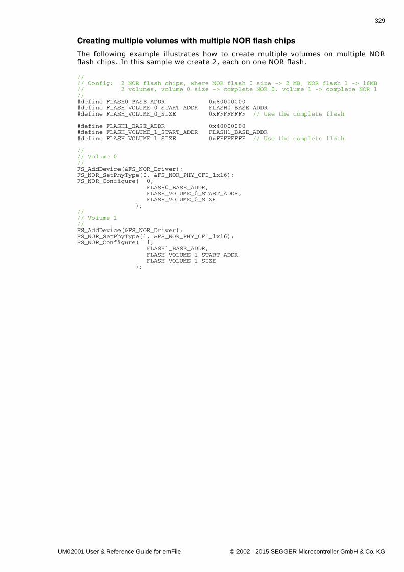
329
Creating multiple volumes with multiple NOR flash chips
The following example illustrates how to create multiple volumes on multiple NORflash chips. In this sample we create 2, each on one NOR flash.
//// Config: 2 NOR flash chips, where NOR flash 0 size -> 2 MB, NOR flash 1 -> 16MB// 2 volumes, volume 0 size -> complete NOR 0, volume 1 -> complete NOR 1//#define FLASH0_BASE_ADDR 0x80000000#define FLASH_VOLUME_0_START_ADDR FLASH0_BASE_ADDR#define FLASH_VOLUME_0_SIZE 0xFFFFFFFF // Use the complete flash
#define FLASH1_BASE_ADDR 0x40000000#define FLASH_VOLUME_1_START_ADDR FLASH1_BASE_ADDR#define FLASH_VOLUME_1_SIZE 0xFFFFFFFF // Use the complete flash
//// Volume 0//FS_AddDevice(&FS_NOR_Driver);FS_NOR_SetPhyType(0, &FS_NOR_PHY_CFI_1x16);FS_NOR_Configure( 0, FLASH0_BASE_ADDR, FLASH_VOLUME_0_START_ADDR, FLASH_VOLUME_0_SIZE );//// Volume 1//FS_AddDevice(&FS_NOR_Driver);FS_NOR_SetPhyType(1, &FS_NOR_PHY_CFI_1x16);FS_NOR_Configure( 1, FLASH1_BASE_ADDR, FLASH_VOLUME_1_START_ADDR, FLASH_VOLUME_1_SIZE );
UM02001 User & Reference Guide for emFile © 2002 - 2015 SEGGER Microcontroller GmbH & Co. KG
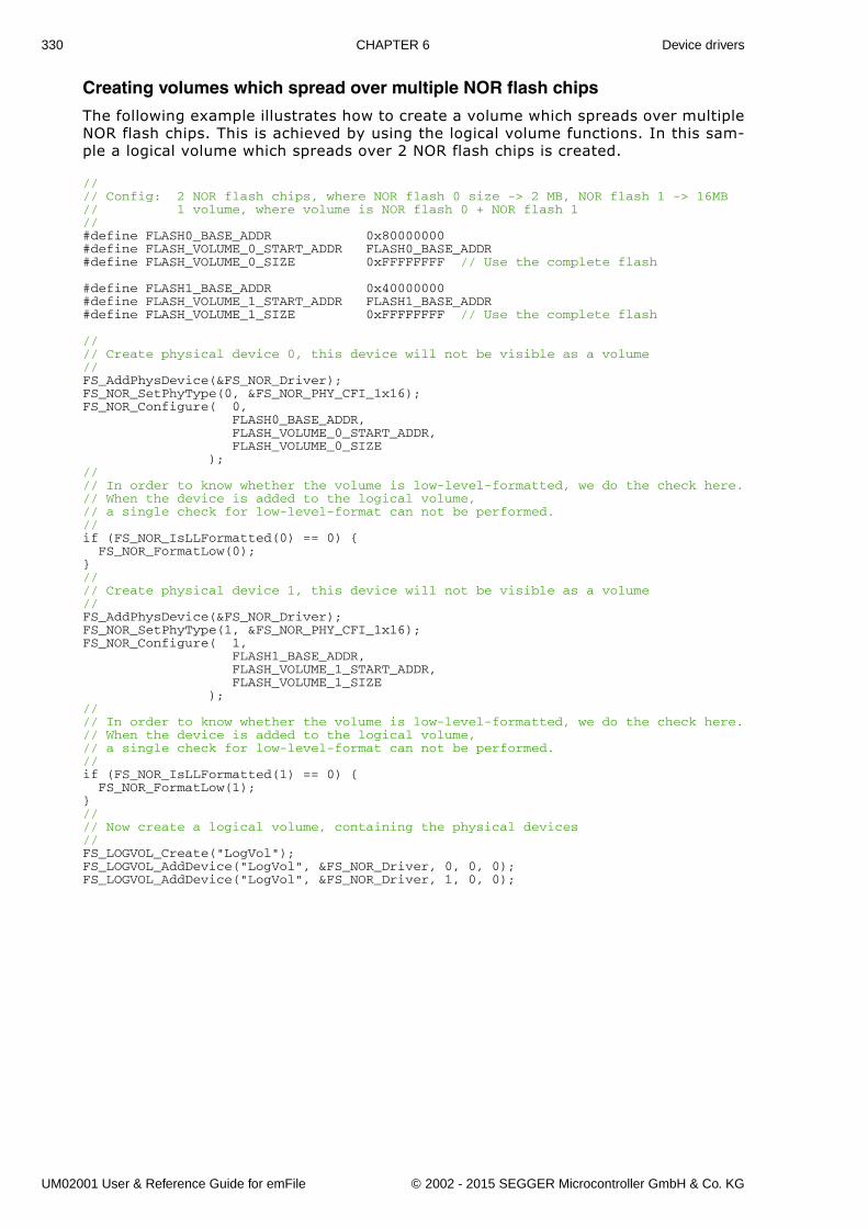
330 CHAPTER 6 Device drivers
Creating volumes which spread over multiple NOR flash chips
The following example illustrates how to create a volume which spreads over multipleNOR flash chips. This is achieved by using the logical volume functions. In this sam-ple a logical volume which spreads over 2 NOR flash chips is created.
//// Config: 2 NOR flash chips, where NOR flash 0 size -> 2 MB, NOR flash 1 -> 16MB// 1 volume, where volume is NOR flash 0 + NOR flash 1//#define FLASH0_BASE_ADDR 0x80000000#define FLASH_VOLUME_0_START_ADDR FLASH0_BASE_ADDR#define FLASH_VOLUME_0_SIZE 0xFFFFFFFF // Use the complete flash
#define FLASH1_BASE_ADDR 0x40000000#define FLASH_VOLUME_1_START_ADDR FLASH1_BASE_ADDR#define FLASH_VOLUME_1_SIZE 0xFFFFFFFF // Use the complete flash
//// Create physical device 0, this device will not be visible as a volume//FS_AddPhysDevice(&FS_NOR_Driver);FS_NOR_SetPhyType(0, &FS_NOR_PHY_CFI_1x16);FS_NOR_Configure( 0, FLASH0_BASE_ADDR, FLASH_VOLUME_0_START_ADDR, FLASH_VOLUME_0_SIZE );//// In order to know whether the volume is low-level-formatted, we do the check here.// When the device is added to the logical volume,// a single check for low-level-format can not be performed.//if (FS_NOR_IsLLFormatted(0) == 0) { FS_NOR_FormatLow(0);}//// Create physical device 1, this device will not be visible as a volume//FS_AddPhysDevice(&FS_NOR_Driver);FS_NOR_SetPhyType(1, &FS_NOR_PHY_CFI_1x16);FS_NOR_Configure( 1, FLASH1_BASE_ADDR, FLASH_VOLUME_1_START_ADDR, FLASH_VOLUME_1_SIZE );//// In order to know whether the volume is low-level-formatted, we do the check here.// When the device is added to the logical volume,// a single check for low-level-format can not be performed.//if (FS_NOR_IsLLFormatted(1) == 0) { FS_NOR_FormatLow(1);}//// Now create a logical volume, containing the physical devices//FS_LOGVOL_Create("LogVol");FS_LOGVOL_AddDevice("LogVol", &FS_NOR_Driver, 0, 0, 0);FS_LOGVOL_AddDevice("LogVol", &FS_NOR_Driver, 1, 0, 0);
UM02001 User & Reference Guide for emFile © 2002 - 2015 SEGGER Microcontroller GmbH & Co. KG
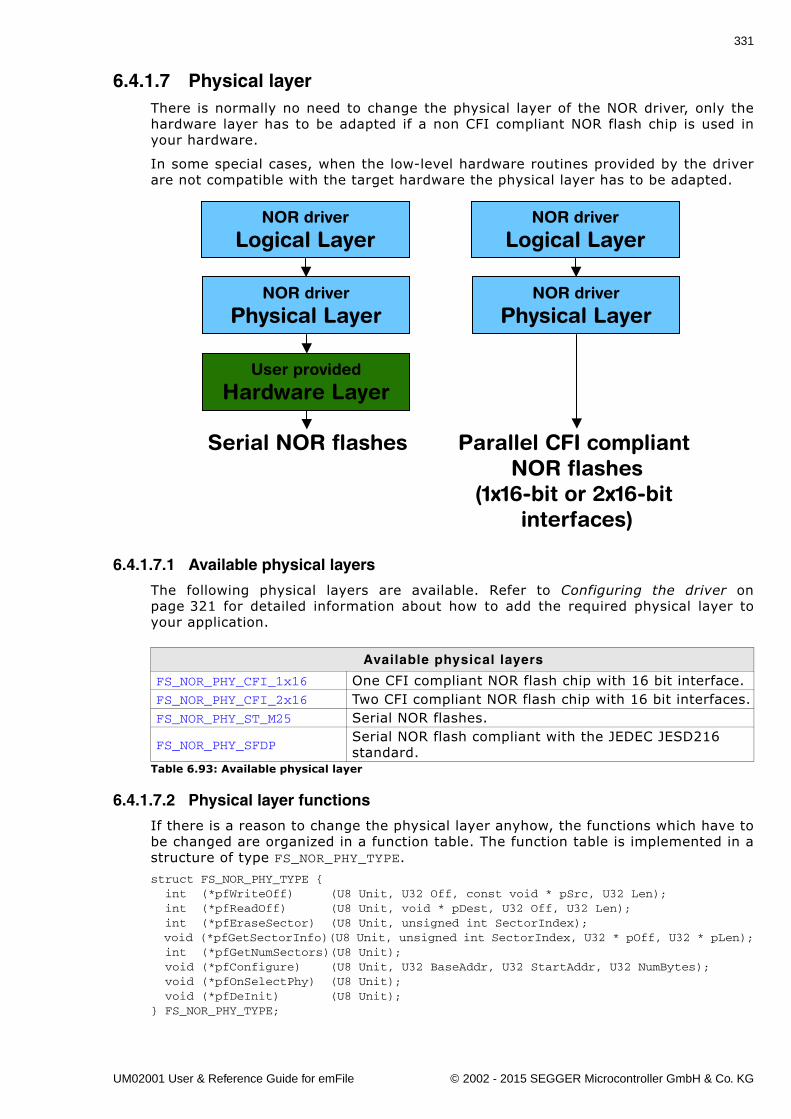
331
6.4.1.7 Physical layerThere is normally no need to change the physical layer of the NOR driver, only thehardware layer has to be adapted if a non CFI compliant NOR flash chip is used inyour hardware.
In some special cases, when the low-level hardware routines provided by the driverare not compatible with the target hardware the physical layer has to be adapted.
6.4.1.7.1 Available physical layers
The following physical layers are available. Refer to Configuring the driver onpage 321 for detailed information about how to add the required physical layer toyour application.
6.4.1.7.2 Physical layer functions
If there is a reason to change the physical layer anyhow, the functions which have tobe changed are organized in a function table. The function table is implemented in astructure of type FS_NOR_PHY_TYPE.
struct FS_NOR_PHY_TYPE { int (*pfWriteOff) (U8 Unit, U32 Off, const void * pSrc, U32 Len); int (*pfReadOff) (U8 Unit, void * pDest, U32 Off, U32 Len); int (*pfEraseSector) (U8 Unit, unsigned int SectorIndex); void (*pfGetSectorInfo)(U8 Unit, unsigned int SectorIndex, U32 * pOff, U32 * pLen); int (*pfGetNumSectors)(U8 Unit); void (*pfConfigure) (U8 Unit, U32 BaseAddr, U32 StartAddr, U32 NumBytes); void (*pfOnSelectPhy) (U8 Unit); void (*pfDeInit) (U8 Unit);} FS_NOR_PHY_TYPE;
Available physical layers
FS_NOR_PHY_CFI_1x16 One CFI compliant NOR flash chip with 16 bit interface.FS_NOR_PHY_CFI_2x16 Two CFI compliant NOR flash chip with 16 bit interfaces.FS_NOR_PHY_ST_M25 Serial NOR flashes.
FS_NOR_PHY_SFDPSerial NOR flash compliant with the JEDEC JESD216 standard.
Table 6.93: Available physical layer
NOR driver
Logical Layer
NOR driver
Physical Layer
User provided
Hardware Layer
NOR driver
Logical Layer
NOR driver
Physical Layer
Serial NOR flashes Parallel CFI compliantNOR flashes
(1x16-bit or 2x16-bit interfaces)
UM02001 User & Reference Guide for emFile © 2002 - 2015 SEGGER Microcontroller GmbH & Co. KG
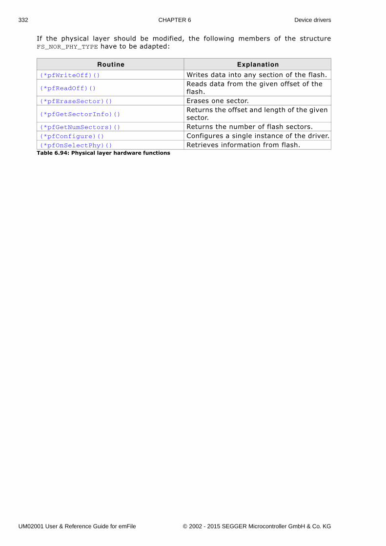
332 CHAPTER 6 Device drivers
If the physical layer should be modified, the following members of the structureFS_NOR_PHY_TYPE have to be adapted:
Routine Explanation
(*pfWriteOff)() Writes data into any section of the flash.
(*pfReadOff)()Reads data from the given offset of the flash.
(*pfEraseSector)() Erases one sector.
(*pfGetSectorInfo)()Returns the offset and length of the given sector.
(*pfGetNumSectors)() Returns the number of flash sectors.(*pfConfigure)() Configures a single instance of the driver.(*pfOnSelectPhy)() Retrieves information from flash.
Table 6.94: Physical layer hardware functions
UM02001 User & Reference Guide for emFile © 2002 - 2015 SEGGER Microcontroller GmbH & Co. KG
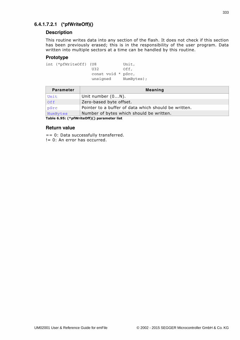
333
6.4.1.7.2.1 (*pfWriteOff)()
Description
This routine writes data into any section of the flash. It does not check if this sectionhas been previously erased; this is in the responsibility of the user program. Datawritten into multiple sectors at a time can be handled by this routine.
Prototypeint (*pfWriteOff) (U8 Unit, U32 Off, const void * pSrc, unsigned NumBytes);
Return value== 0: Data successfully transferred.!= 0: An error has occurred.
Parameter Meaning
Unit Unit number (0...N).Off Zero-based byte offset.pSrc Pointer to a buffer of data which should be written.NumBytes Number of bytes which should be written.
Table 6.95: (*pfWriteOff)() parameter list
UM02001 User & Reference Guide for emFile © 2002 - 2015 SEGGER Microcontroller GmbH & Co. KG
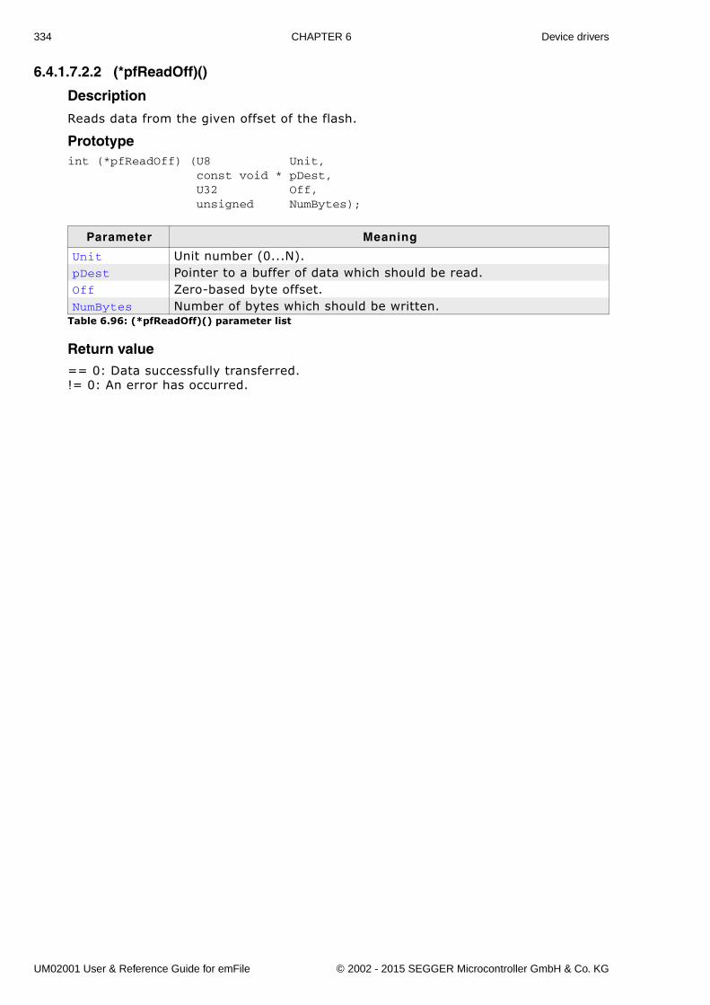
334 CHAPTER 6 Device drivers
6.4.1.7.2.2 (*pfReadOff)()
Description
Reads data from the given offset of the flash.
Prototypeint (*pfReadOff) (U8 Unit, const void * pDest, U32 Off, unsigned NumBytes);
Return value== 0: Data successfully transferred.!= 0: An error has occurred.
Parameter Meaning
Unit Unit number (0...N).pDest Pointer to a buffer of data which should be read.Off Zero-based byte offset.NumBytes Number of bytes which should be written.
Table 6.96: (*pfReadOff)() parameter list
UM02001 User & Reference Guide for emFile © 2002 - 2015 SEGGER Microcontroller GmbH & Co. KG
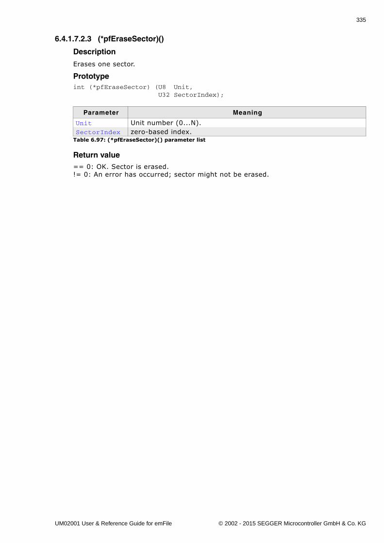
335
6.4.1.7.2.3 (*pfEraseSector)()
Description
Erases one sector.
Prototypeint (*pfEraseSector) (U8 Unit, U32 SectorIndex);
Return value== 0: OK. Sector is erased.!= 0: An error has occurred; sector might not be erased.
Parameter Meaning
Unit Unit number (0...N).SectorIndex zero-based index.
Table 6.97: (*pfEraseSector)() parameter list
UM02001 User & Reference Guide for emFile © 2002 - 2015 SEGGER Microcontroller GmbH & Co. KG
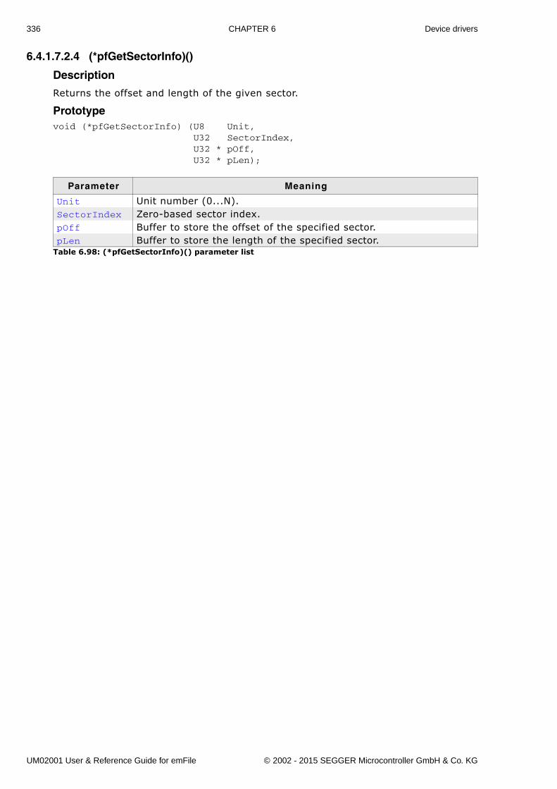
336 CHAPTER 6 Device drivers
6.4.1.7.2.4 (*pfGetSectorInfo)()
Description
Returns the offset and length of the given sector.
Prototypevoid (*pfGetSectorInfo) (U8 Unit, U32 SectorIndex, U32 * pOff, U32 * pLen);
Parameter Meaning
Unit Unit number (0...N).SectorIndex Zero-based sector index.pOff Buffer to store the offset of the specified sector.pLen Buffer to store the length of the specified sector.
Table 6.98: (*pfGetSectorInfo)() parameter list
UM02001 User & Reference Guide for emFile © 2002 - 2015 SEGGER Microcontroller GmbH & Co. KG
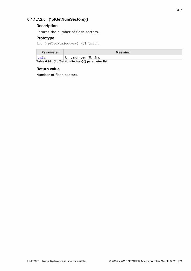
337
6.4.1.7.2.5 (*pfGetNumSectors)()
Description
Returns the number of flash sectors.
Prototypeint (*pfGetNumSectors) (U8 Unit);
Return valueNumber of flash sectors.
Parameter Meaning
Unit Unit number (0...N).Table 6.99: (*pfGetNumSectors)() parameter list
UM02001 User & Reference Guide for emFile © 2002 - 2015 SEGGER Microcontroller GmbH & Co. KG
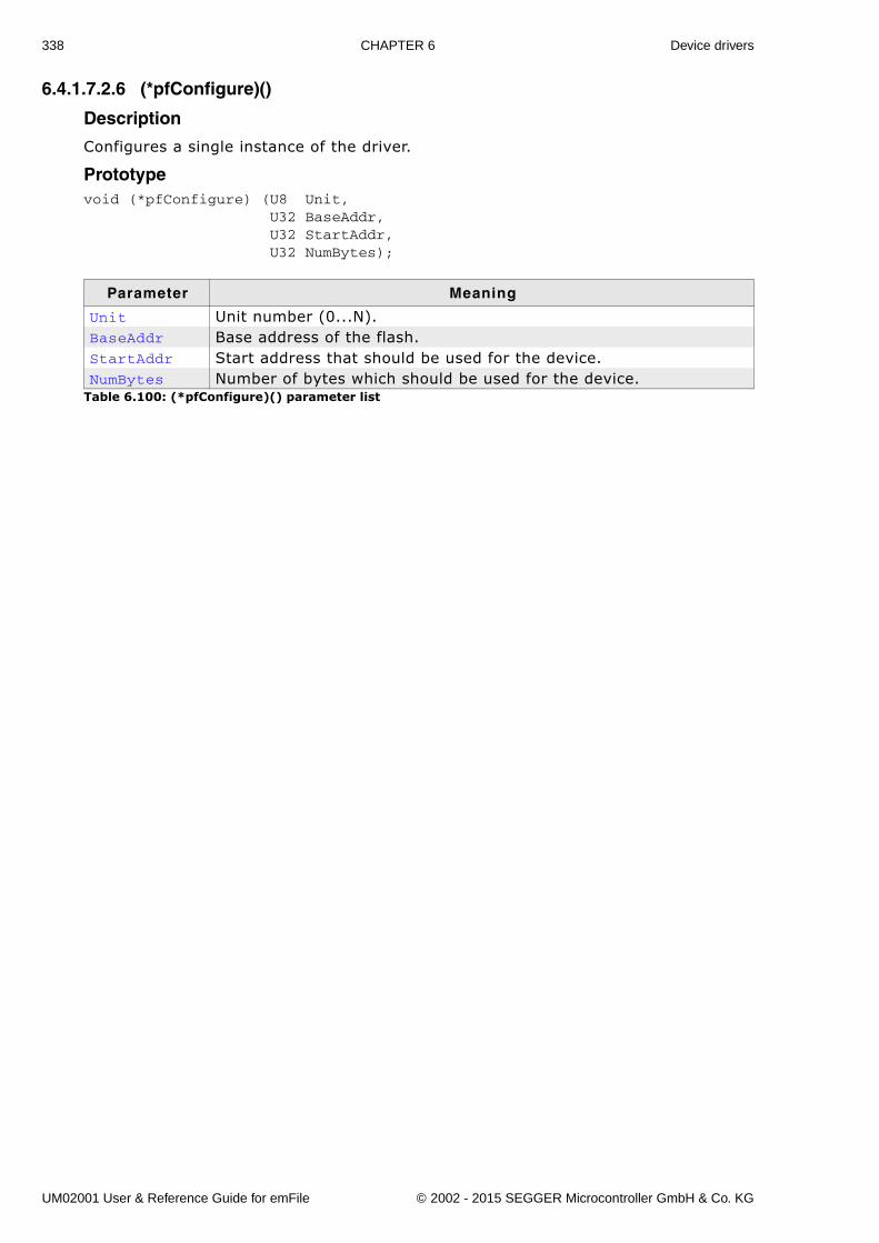
338 CHAPTER 6 Device drivers
6.4.1.7.2.6 (*pfConfigure)()
Description
Configures a single instance of the driver.
Prototypevoid (*pfConfigure) (U8 Unit, U32 BaseAddr, U32 StartAddr, U32 NumBytes);
Parameter Meaning
Unit Unit number (0...N).BaseAddr Base address of the flash.StartAddr Start address that should be used for the device.NumBytes Number of bytes which should be used for the device.
Table 6.100: (*pfConfigure)() parameter list
UM02001 User & Reference Guide for emFile © 2002 - 2015 SEGGER Microcontroller GmbH & Co. KG
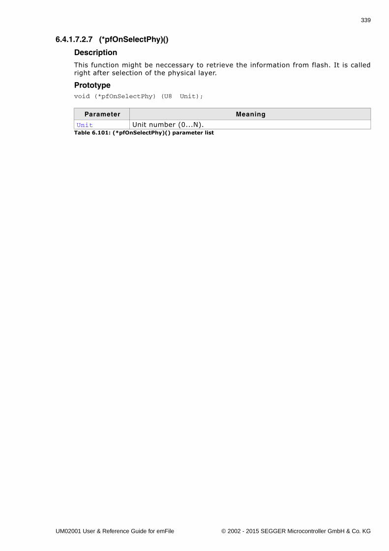
339
6.4.1.7.2.7 (*pfOnSelectPhy)()
Description
This function might be neccessary to retrieve the information from flash. It is calledright after selection of the physical layer.
Prototypevoid (*pfOnSelectPhy) (U8 Unit);
Parameter Meaning
Unit Unit number (0...N).Table 6.101: (*pfOnSelectPhy)() parameter list
UM02001 User & Reference Guide for emFile © 2002 - 2015 SEGGER Microcontroller GmbH & Co. KG
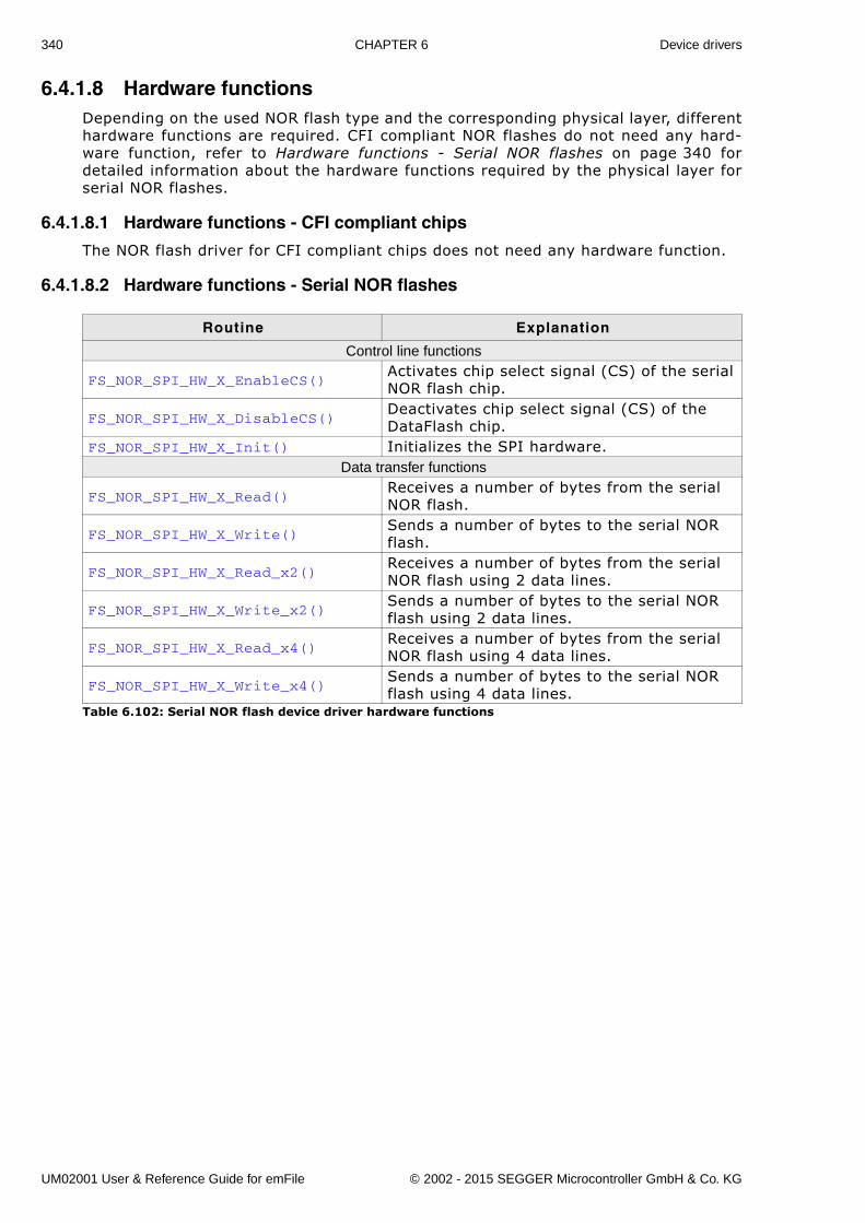
340 CHAPTER 6 Device drivers
6.4.1.8 Hardware functionsDepending on the used NOR flash type and the corresponding physical layer, differenthardware functions are required. CFI compliant NOR flashes do not need any hard-ware function, refer to Hardware functions - Serial NOR flashes on page 340 fordetailed information about the hardware functions required by the physical layer forserial NOR flashes.
6.4.1.8.1 Hardware functions - CFI compliant chips
The NOR flash driver for CFI compliant chips does not need any hardware function.
6.4.1.8.2 Hardware functions - Serial NOR flashes
Routine Explanation
Control line functions
FS_NOR_SPI_HW_X_EnableCS()Activates chip select signal (CS) of the serial NOR flash chip.
FS_NOR_SPI_HW_X_DisableCS()Deactivates chip select signal (CS) of the DataFlash chip.
FS_NOR_SPI_HW_X_Init() Initializes the SPI hardware.Data transfer functions
FS_NOR_SPI_HW_X_Read()Receives a number of bytes from the serial NOR flash.
FS_NOR_SPI_HW_X_Write()Sends a number of bytes to the serial NOR flash.
FS_NOR_SPI_HW_X_Read_x2()Receives a number of bytes from the serial NOR flash using 2 data lines.
FS_NOR_SPI_HW_X_Write_x2()Sends a number of bytes to the serial NOR flash using 2 data lines.
FS_NOR_SPI_HW_X_Read_x4()Receives a number of bytes from the serial NOR flash using 4 data lines.
FS_NOR_SPI_HW_X_Write_x4()Sends a number of bytes to the serial NOR flash using 4 data lines.
Table 6.102: Serial NOR flash device driver hardware functions
UM02001 User & Reference Guide for emFile © 2002 - 2015 SEGGER Microcontroller GmbH & Co. KG
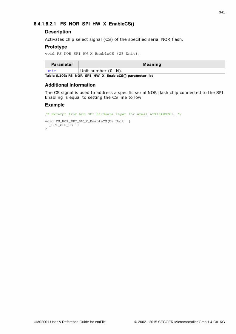
341
6.4.1.8.2.1 FS_NOR_SPI_HW_X_EnableCS()
Description
Activates chip select signal (CS) of the specified serial NOR flash.
Prototypevoid FS_NOR_SPI_HW_X_EnableCS (U8 Unit);
Additional Information
The CS signal is used to address a specific serial NOR flash chip connected to the SPI.Enabling is equal to setting the CS line to low.
Example
/* Excerpt from NOR SPI hardware layer for Atmel AT91SAM9261. */
void FS_NOR_SPI_HW_X_EnableCS(U8 Unit) { _SPI_CLR_CS();}
Parameter Meaning
Unit Unit number (0�N).Table 6.103: FS_NOR_SPI_HW_X_EnableCS() parameter list
UM02001 User & Reference Guide for emFile © 2002 - 2015 SEGGER Microcontroller GmbH & Co. KG
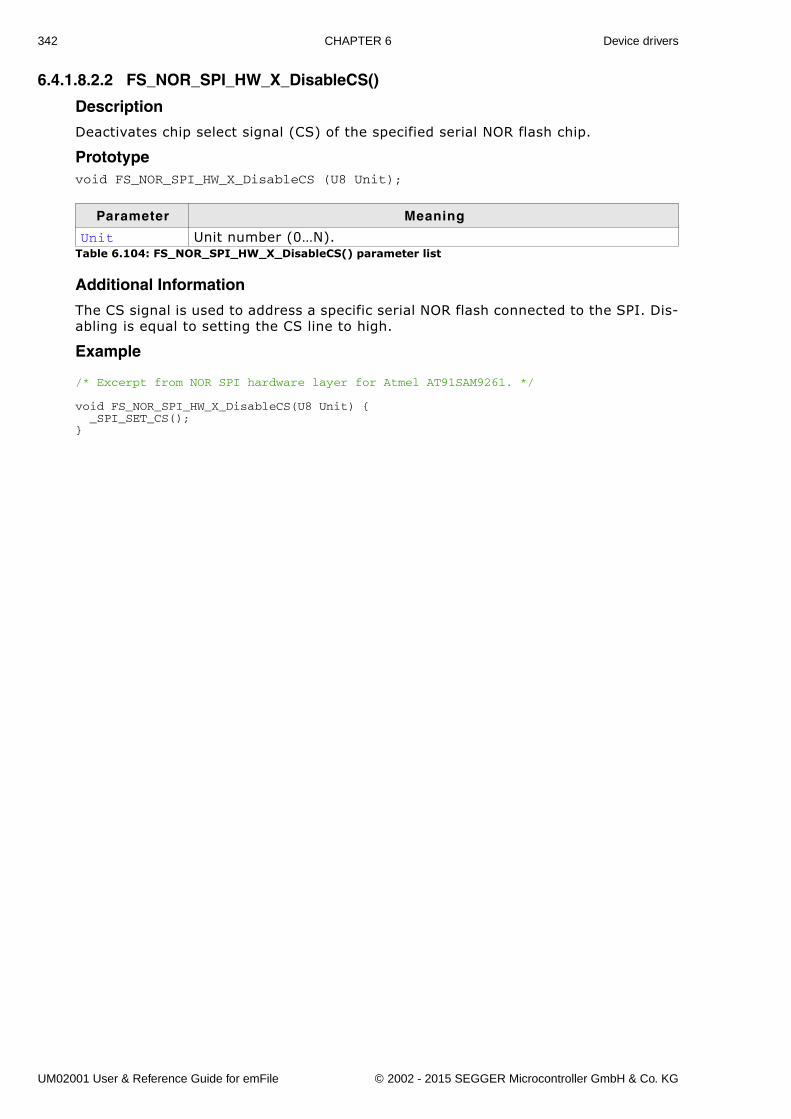
342 CHAPTER 6 Device drivers
6.4.1.8.2.2 FS_NOR_SPI_HW_X_DisableCS()
Description
Deactivates chip select signal (CS) of the specified serial NOR flash chip.
Prototypevoid FS_NOR_SPI_HW_X_DisableCS (U8 Unit);
Additional Information
The CS signal is used to address a specific serial NOR flash connected to the SPI. Dis-abling is equal to setting the CS line to high.
Example
/* Excerpt from NOR SPI hardware layer for Atmel AT91SAM9261. */
void FS_NOR_SPI_HW_X_DisableCS(U8 Unit) { _SPI_SET_CS();}
Parameter Meaning
Unit Unit number (0�N).Table 6.104: FS_NOR_SPI_HW_X_DisableCS() parameter list
UM02001 User & Reference Guide for emFile © 2002 - 2015 SEGGER Microcontroller GmbH & Co. KG
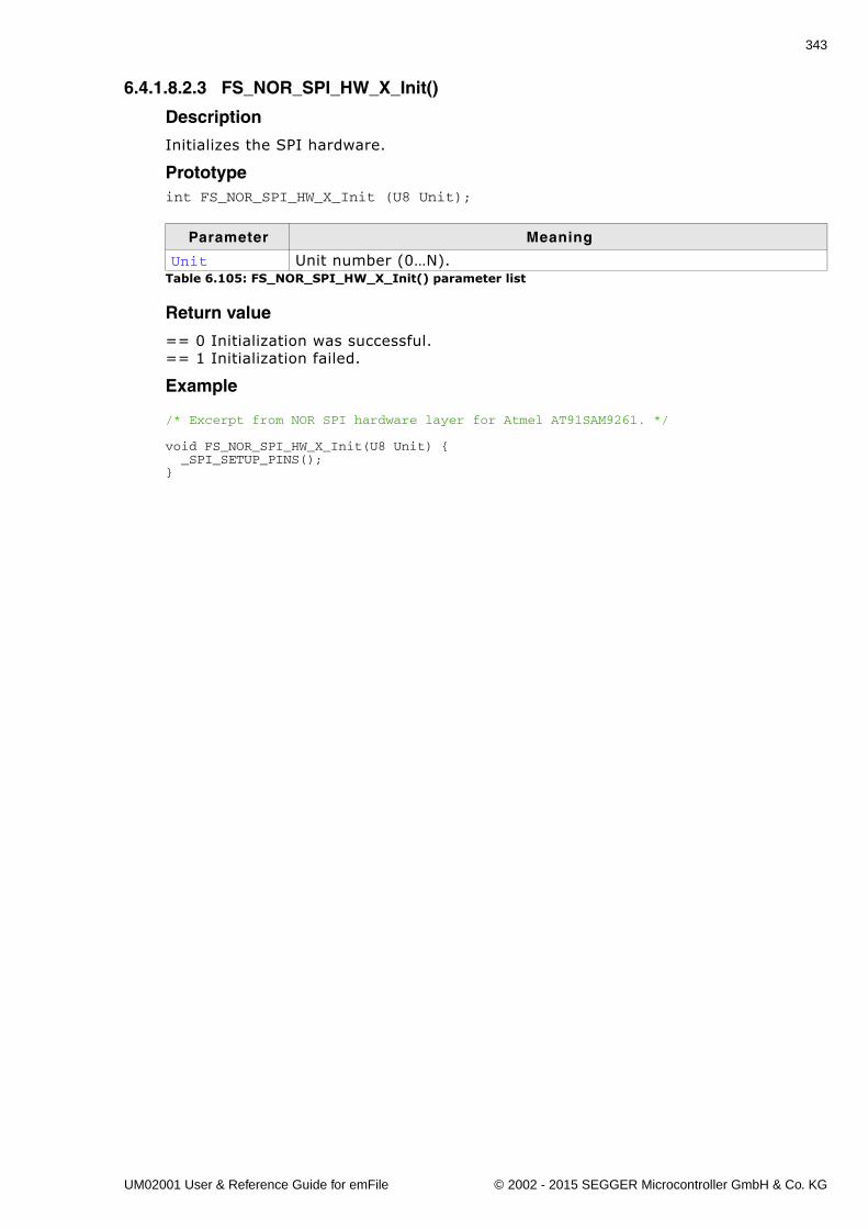
343
6.4.1.8.2.3 FS_NOR_SPI_HW_X_Init()
Description
Initializes the SPI hardware.
Prototypeint FS_NOR_SPI_HW_X_Init (U8 Unit);
Return value
== 0 Initialization was successful.== 1 Initialization failed.
Example
/* Excerpt from NOR SPI hardware layer for Atmel AT91SAM9261. */
void FS_NOR_SPI_HW_X_Init(U8 Unit) { _SPI_SETUP_PINS();}
Parameter Meaning
Unit Unit number (0�N).Table 6.105: FS_NOR_SPI_HW_X_Init() parameter list
UM02001 User & Reference Guide for emFile © 2002 - 2015 SEGGER Microcontroller GmbH & Co. KG
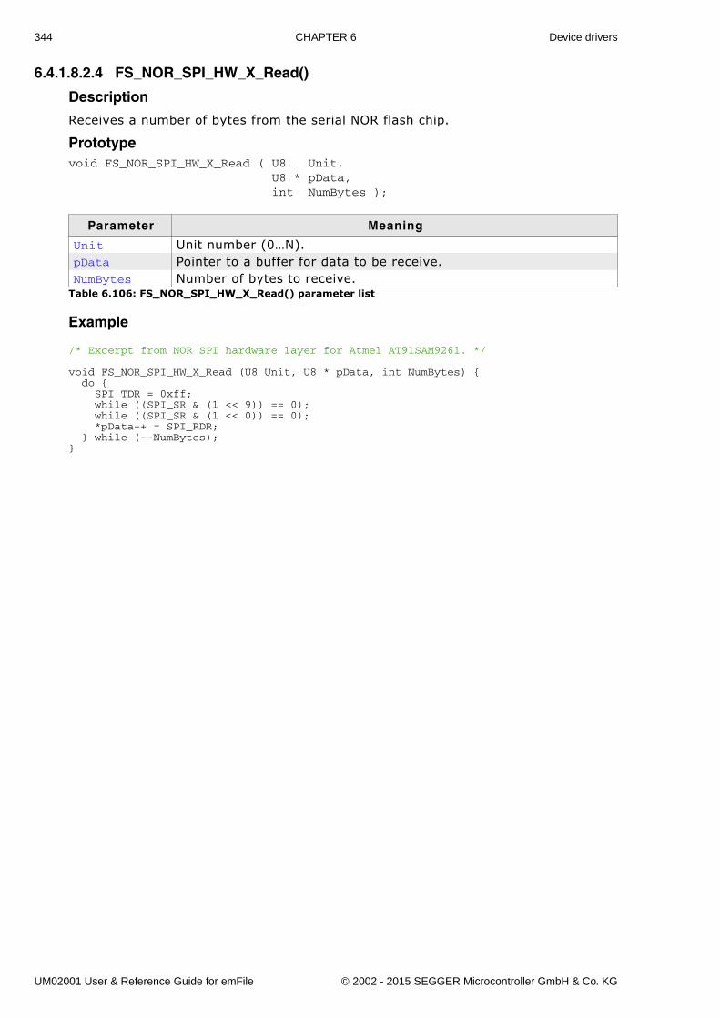
344 CHAPTER 6 Device drivers
6.4.1.8.2.4 FS_NOR_SPI_HW_X_Read()
Description
Receives a number of bytes from the serial NOR flash chip.
Prototypevoid FS_NOR_SPI_HW_X_Read ( U8 Unit, U8 * pData, int NumBytes );
Example
/* Excerpt from NOR SPI hardware layer for Atmel AT91SAM9261. */
void FS_NOR_SPI_HW_X_Read (U8 Unit, U8 * pData, int NumBytes) { do { SPI_TDR = 0xff; while ((SPI_SR & (1 << 9)) == 0); while ((SPI_SR & (1 << 0)) == 0); *pData++ = SPI_RDR; } while (--NumBytes);}
Parameter Meaning
Unit Unit number (0�N).pData Pointer to a buffer for data to be receive.NumBytes Number of bytes to receive.
Table 6.106: FS_NOR_SPI_HW_X_Read() parameter list
UM02001 User & Reference Guide for emFile © 2002 - 2015 SEGGER Microcontroller GmbH & Co. KG
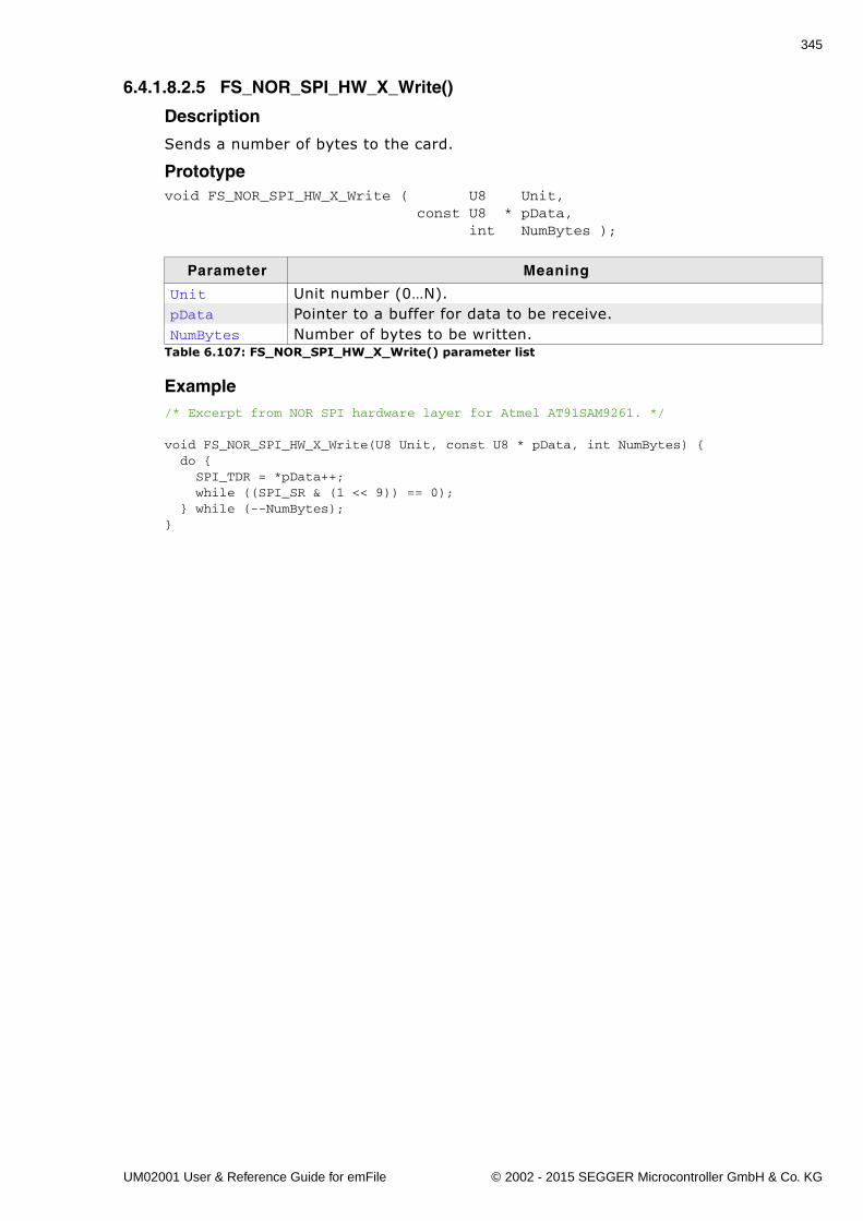
345
6.4.1.8.2.5 FS_NOR_SPI_HW_X_Write()
Description
Sends a number of bytes to the card.
Prototypevoid FS_NOR_SPI_HW_X_Write ( U8 Unit, const U8 * pData, int NumBytes );
Example/* Excerpt from NOR SPI hardware layer for Atmel AT91SAM9261. */
void FS_NOR_SPI_HW_X_Write(U8 Unit, const U8 * pData, int NumBytes) { do { SPI_TDR = *pData++; while ((SPI_SR & (1 << 9)) == 0); } while (--NumBytes);}
Parameter Meaning
Unit Unit number (0�N).pData Pointer to a buffer for data to be receive.NumBytes Number of bytes to be written.
Table 6.107: FS_NOR_SPI_HW_X_Write() parameter list
UM02001 User & Reference Guide for emFile © 2002 - 2015 SEGGER Microcontroller GmbH & Co. KG
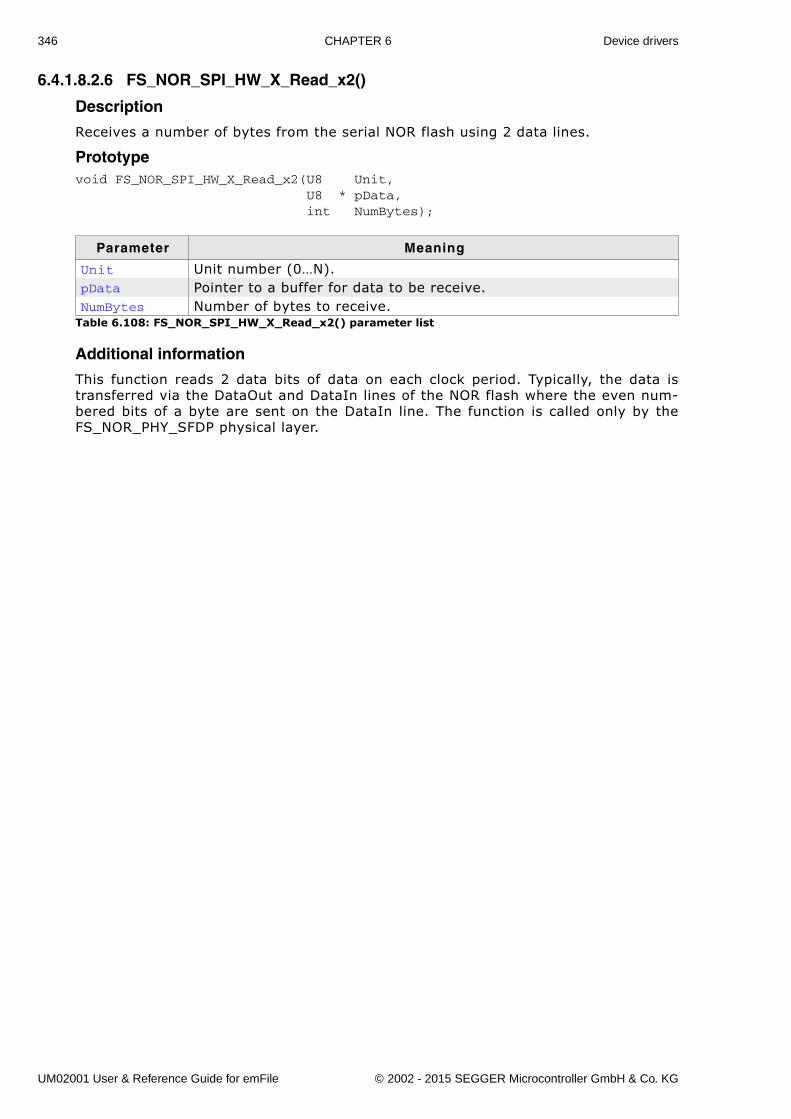
346 CHAPTER 6 Device drivers
6.4.1.8.2.6 FS_NOR_SPI_HW_X_Read_x2()
Description
Receives a number of bytes from the serial NOR flash using 2 data lines.
Prototypevoid FS_NOR_SPI_HW_X_Read_x2(U8 Unit, U8 * pData, int NumBytes);
Additional information
This function reads 2 data bits of data on each clock period. Typically, the data istransferred via the DataOut and DataIn lines of the NOR flash where the even num-bered bits of a byte are sent on the DataIn line. The function is called only by theFS_NOR_PHY_SFDP physical layer.
Parameter Meaning
Unit Unit number (0�N).pData Pointer to a buffer for data to be receive.NumBytes Number of bytes to receive.
Table 6.108: FS_NOR_SPI_HW_X_Read_x2() parameter list
UM02001 User & Reference Guide for emFile © 2002 - 2015 SEGGER Microcontroller GmbH & Co. KG
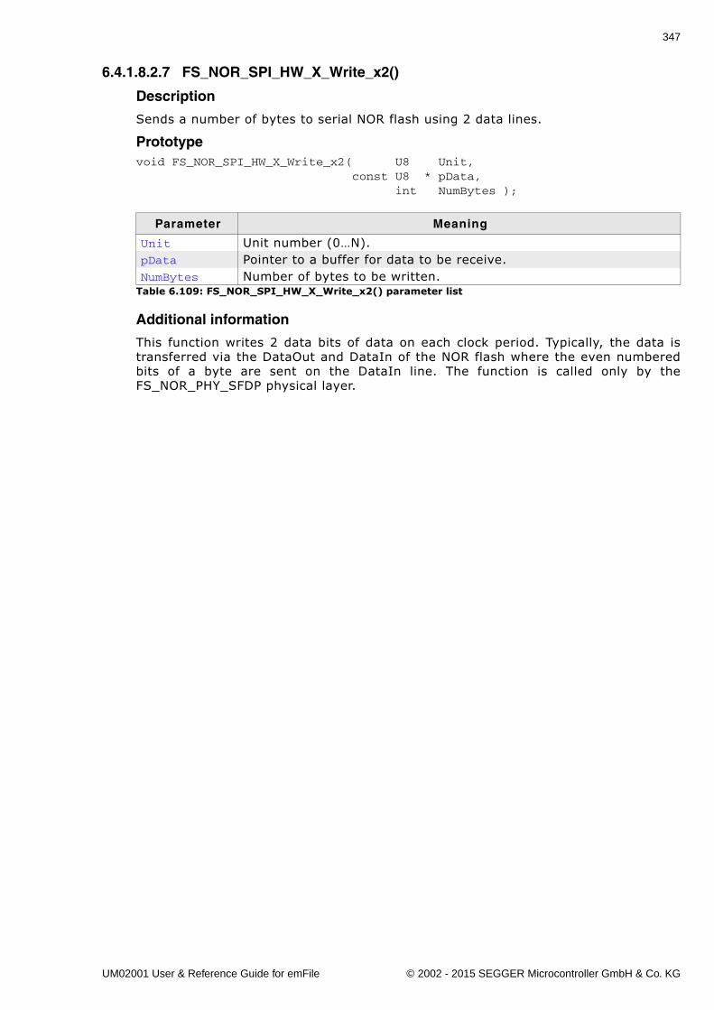
347
6.4.1.8.2.7 FS_NOR_SPI_HW_X_Write_x2()
Description
Sends a number of bytes to serial NOR flash using 2 data lines.
Prototypevoid FS_NOR_SPI_HW_X_Write_x2( U8 Unit, const U8 * pData, int NumBytes );
Additional information
This function writes 2 data bits of data on each clock period. Typically, the data istransferred via the DataOut and DataIn of the NOR flash where the even numberedbits of a byte are sent on the DataIn line. The function is called only by theFS_NOR_PHY_SFDP physical layer.
Parameter Meaning
Unit Unit number (0�N).pData Pointer to a buffer for data to be receive.NumBytes Number of bytes to be written.
Table 6.109: FS_NOR_SPI_HW_X_Write_x2() parameter list
UM02001 User & Reference Guide for emFile © 2002 - 2015 SEGGER Microcontroller GmbH & Co. KG
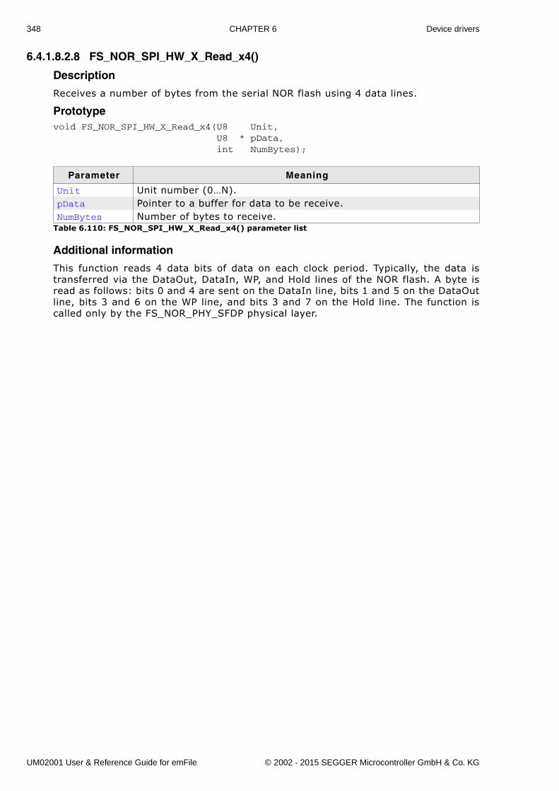
348 CHAPTER 6 Device drivers
6.4.1.8.2.8 FS_NOR_SPI_HW_X_Read_x4()
Description
Receives a number of bytes from the serial NOR flash using 4 data lines.
Prototypevoid FS_NOR_SPI_HW_X_Read_x4(U8 Unit, U8 * pData, int NumBytes);
Additional information
This function reads 4 data bits of data on each clock period. Typically, the data istransferred via the DataOut, DataIn, WP, and Hold lines of the NOR flash. A byte isread as follows: bits 0 and 4 are sent on the DataIn line, bits 1 and 5 on the DataOutline, bits 3 and 6 on the WP line, and bits 3 and 7 on the Hold line. The function iscalled only by the FS_NOR_PHY_SFDP physical layer.
Parameter Meaning
Unit Unit number (0�N).pData Pointer to a buffer for data to be receive.NumBytes Number of bytes to receive.
Table 6.110: FS_NOR_SPI_HW_X_Read_x4() parameter list
UM02001 User & Reference Guide for emFile © 2002 - 2015 SEGGER Microcontroller GmbH & Co. KG
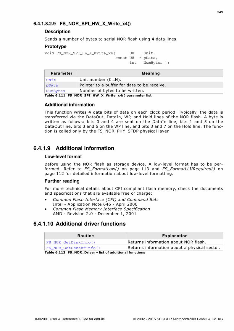
349
6.4.1.8.2.9 FS_NOR_SPI_HW_X_Write_x4()
Description
Sends a number of bytes to serial NOR flash using 4 data lines.
Prototypevoid FS_NOR_SPI_HW_X_Write_x4( U8 Unit, const U8 * pData, int NumBytes );
Additional information
This function writes 4 data bits of data on each clock period. Typically, the data istransferred via the DataOut, DataIn, WP, and Hold lines of the NOR flash. A byte iswritten as follows: bits 0 and 4 are sent on the DataIn line, bits 1 and 5 on theDataOut line, bits 3 and 6 on the WP line, and bits 3 and 7 on the Hold line. The func-tion is called only by the FS_NOR_PHY_SFDP physical layer.
6.4.1.9 Additional informationLow-level format
Before using the NOR flash as storage device. A low-level format has to be per-formed. Refer to FS_FormatLow() on page 113 and FS_FormatLLIfRequired() onpage 112 for detailed information about low-level formatting.
Further reading
For more technical details about CFI compliant flash memory, check the documentsand specifications that are available free of charge:
� Common Flash Interface (CFI) and Command SetsIntel - Application Note 646 - April 2000
� Common Flash Memory Interface SpecificationAMD - Revision 2.0 - December 1, 2001
6.4.1.10 Additional driver functions
Parameter Meaning
Unit Unit number (0�N).pData Pointer to a buffer for data to be receive.NumBytes Number of bytes to be written.
Table 6.111: FS_NOR_SPI_HW_X_Write_x4() parameter list
Routine Explanation
FS_NOR_GetDiskInfo() Returns information about NOR flash.FS_NOR_GetSectorInfo() Returns information about a physical sector.
Table 6.112: FS_NOR_Driver - list of additional functions
UM02001 User & Reference Guide for emFile © 2002 - 2015 SEGGER Microcontroller GmbH & Co. KG
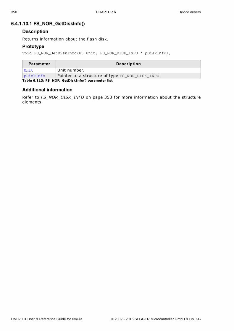
350 CHAPTER 6 Device drivers
6.4.1.10.1 FS_NOR_GetDiskInfo()
Description
Returns information about the flash disk.
Prototypevoid FS_NOR_GetDiskInfo(U8 Unit, FS_NOR_DISK_INFO * pDiskInfo);
Additional information
Refer to FS_NOR_DISK_INFO on page 353 for more information about the structureelements.
Parameter Description
Unit Unit number.pDiskInfo Pointer to a structure of type FS_NOR_DISK_INFO.
Table 6.113: FS_NOR_GetDiskInfo() parameter list
UM02001 User & Reference Guide for emFile © 2002 - 2015 SEGGER Microcontroller GmbH & Co. KG
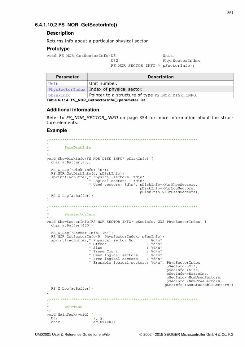
351
6.4.1.10.2 FS_NOR_GetSectorInfo()
Description
Returns info about a particular physical sector.
Prototypevoid FS_NOR_GetSectorInfo(U8 Unit, U32 PhysSectorIndex, FS_NOR_SECTOR_INFO * pSectorInfo);
Additional information
Refer to FS_NOR_SECTOR_INFO on page 354 for more information about the struc-ture elements.
Example
/********************************************************************* ShowDiskInfo**/void ShowDiskInfo(FS_NOR_DISK_INFO* pDiskInfo) { char acBuffer[80];
FS_X_Log("Disk Info: \n"); FS_NOR_GetDiskInfo(0, pDiskInfo); sprintf(acBuffer," Physical sectors: %d\n" " Logical sectors : %d\n" " Used sectors: %d\n", pDiskInfo->NumPhysSectors, pDiskInfo->NumLogSectors, pDiskInfo->NumUsedSectors); FS_X_Log(acBuffer);}
/********************************************************************* ShowSectorInfo*/void ShowSectorInfo(FS_NOR_SECTOR_INFO* pSecInfo, U32 PhysSectorIndex) { char acBuffer[400];
FS_X_Log("Sector Info: \n"); FS_NOR_GetSectorInfo(0, PhysSectorIndex, pSecInfo); sprintf(acBuffer," Physical sector No. : %d\n" " Offset : %d\n" " Size : %d\n" " Erase Count : %d\n" " Used logical sectors : %d\n" " Free logical sectors : %d\n" " Erasable logical sectors: %d\n", PhysSectorIndex, pSecInfo->Off, pSecInfo->Size, pSecInfo->EraseCnt, pSecInfo->NumUsedSectors, pSecInfo->NumFreeSectors, pSecInfo->NumEraseableSectors); FS_X_Log(acBuffer);}
/********************************************************************* MainTask*/void MainTask(void) { U32 i, j; char ac[0x400];
Parameter Description
Unit Unit number.PhysSectorIndex Index of physical sector.pDiskInfo Pointer to a structure of type FS_NOR_DISK_INFO.
Table 6.114: FS_NOR_GetSectorInfo() parameter list
UM02001 User & Reference Guide for emFile © 2002 - 2015 SEGGER Microcontroller GmbH & Co. KG
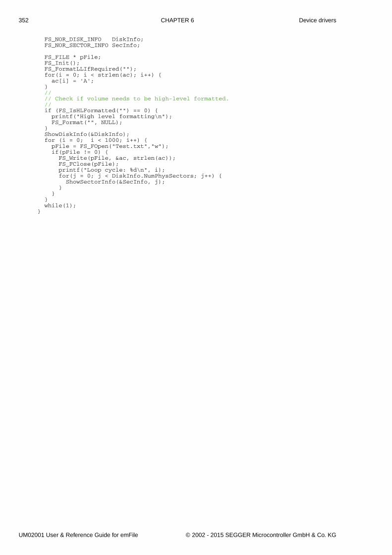
352 CHAPTER 6 Device drivers
FS_NOR_DISK_INFO DiskInfo; FS_NOR_SECTOR_INFO SecInfo;
FS_FILE * pFile; FS_Init(); FS_FormatLLIfRequired(""); for(i = 0; i < strlen(ac); i++) { ac[i] = 'A'; } // // Check if volume needs to be high-level formatted. // if (FS_IsHLFormatted("") == 0) { printf("High level formatting\n"); FS_Format("", NULL); } ShowDiskInfo(&DiskInfo); for (i = 0; i < 1000; i++) { pFile = FS_FOpen("Test.txt","w"); if(pFile != 0) { FS_Write(pFile, &ac, strlen(ac)); FS_FClose(pFile); printf("Loop cycle: %d\n", i); for(j = 0; j < DiskInfo.NumPhysSectors; j++) { ShowSectorInfo(&SecInfo, j); } } } while(1);}
UM02001 User & Reference Guide for emFile © 2002 - 2015 SEGGER Microcontroller GmbH & Co. KG
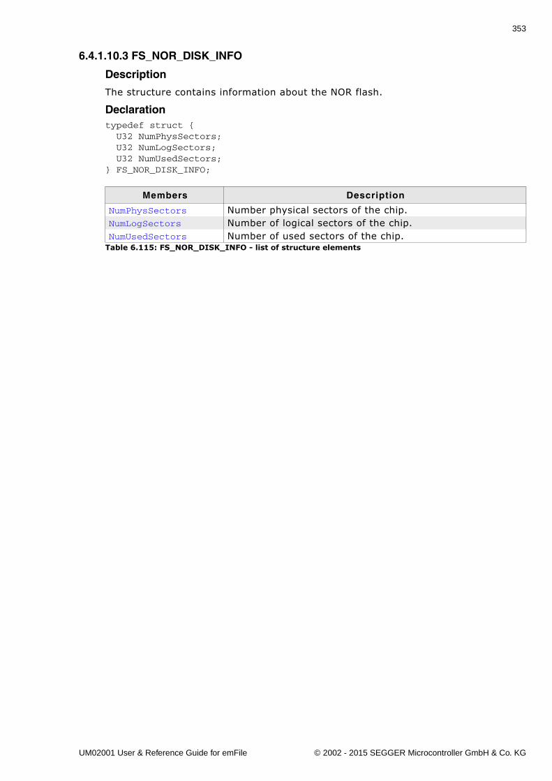
353
6.4.1.10.3 FS_NOR_DISK_INFO
Description
The structure contains information about the NOR flash.
Declarationtypedef struct { U32 NumPhysSectors; U32 NumLogSectors; U32 NumUsedSectors;} FS_NOR_DISK_INFO;
Members Description
NumPhysSectors Number physical sectors of the chip.NumLogSectors Number of logical sectors of the chip.NumUsedSectors Number of used sectors of the chip.
Table 6.115: FS_NOR_DISK_INFO - list of structure elements
UM02001 User & Reference Guide for emFile © 2002 - 2015 SEGGER Microcontroller GmbH & Co. KG
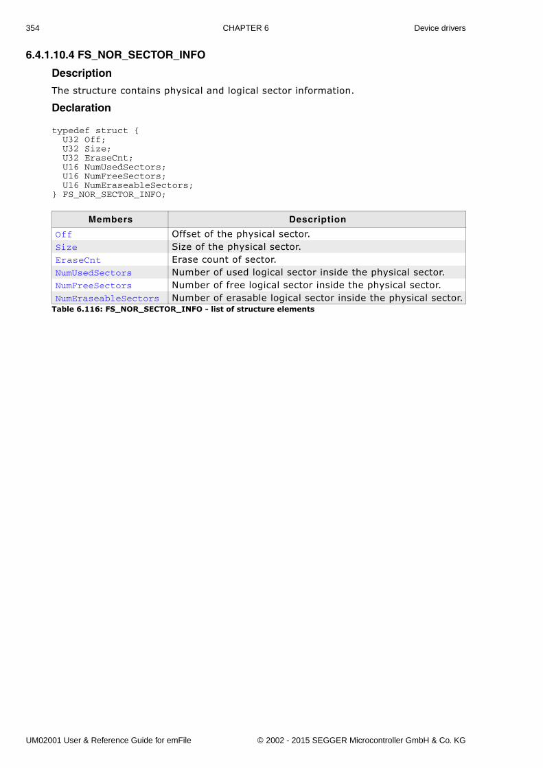
354 CHAPTER 6 Device drivers
6.4.1.10.4 FS_NOR_SECTOR_INFO
Description
The structure contains physical and logical sector information.
Declaration
typedef struct { U32 Off; U32 Size; U32 EraseCnt; U16 NumUsedSectors; U16 NumFreeSectors; U16 NumEraseableSectors;} FS_NOR_SECTOR_INFO;
Members Description
Off Offset of the physical sector.Size Size of the physical sector.EraseCnt Erase count of sector.NumUsedSectors Number of used logical sector inside the physical sector.NumFreeSectors Number of free logical sector inside the physical sector.NumEraseableSectors Number of erasable logical sector inside the physical sector.
Table 6.116: FS_NOR_SECTOR_INFO - list of structure elements
UM02001 User & Reference Guide for emFile © 2002 - 2015 SEGGER Microcontroller GmbH & Co. KG
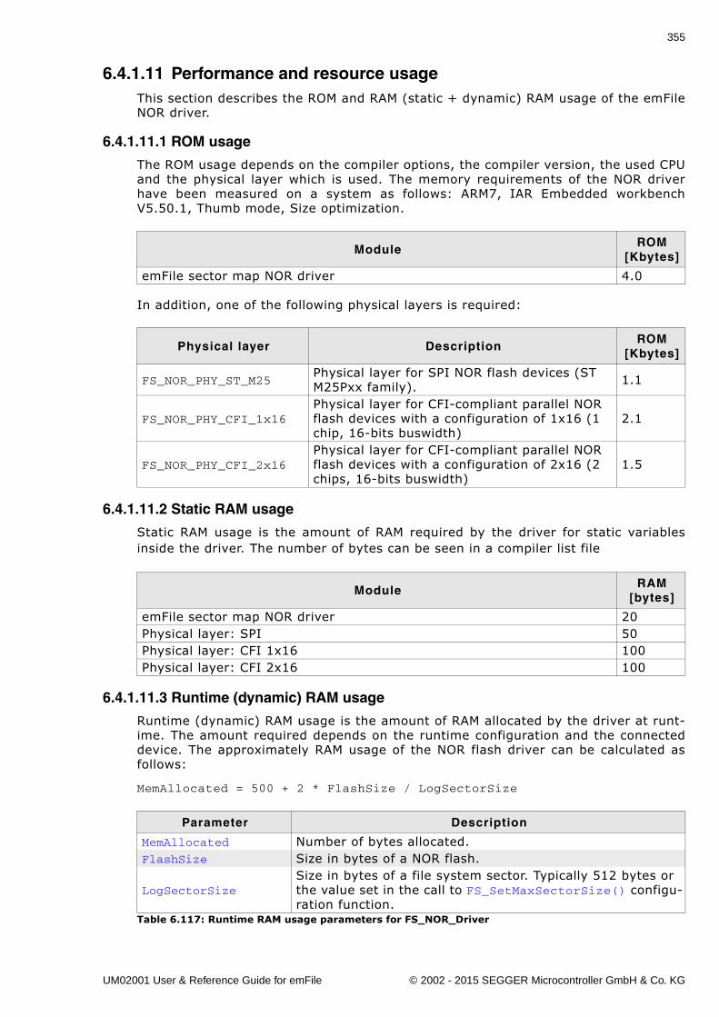
355
6.4.1.11 Performance and resource usageThis section describes the ROM and RAM (static + dynamic) RAM usage of the emFileNOR driver.
6.4.1.11.1 ROM usage
The ROM usage depends on the compiler options, the compiler version, the used CPUand the physical layer which is used. The memory requirements of the NOR driverhave been measured on a system as follows: ARM7, IAR Embedded workbenchV5.50.1, Thumb mode, Size optimization.
In addition, one of the following physical layers is required:
6.4.1.11.2 Static RAM usage
Static RAM usage is the amount of RAM required by the driver for static variablesinside the driver. The number of bytes can be seen in a compiler list file
6.4.1.11.3 Runtime (dynamic) RAM usage
Runtime (dynamic) RAM usage is the amount of RAM allocated by the driver at runt-ime. The amount required depends on the runtime configuration and the connecteddevice. The approximately RAM usage of the NOR flash driver can be calculated asfollows:
MemAllocated = 500 + 2 * FlashSize / LogSectorSize
ModuleROM
[Kbytes]
emFile sector map NOR driver 4.0
Physical layer DescriptionROM
[Kbytes]
FS_NOR_PHY_ST_M25Physical layer for SPI NOR flash devices (ST M25Pxx family). 1.1
FS_NOR_PHY_CFI_1x16Physical layer for CFI-compliant parallel NOR flash devices with a configuration of 1x16 (1 chip, 16-bits buswidth)
2.1
FS_NOR_PHY_CFI_2x16Physical layer for CFI-compliant parallel NOR flash devices with a configuration of 2x16 (2 chips, 16-bits buswidth)
1.5
ModuleRAM
[bytes]
emFile sector map NOR driver 20Physical layer: SPI 50Physical layer: CFI 1x16 100Physical layer: CFI 2x16 100
Parameter Description
MemAllocated Number of bytes allocated.FlashSize Size in bytes of a NOR flash.
LogSectorSizeSize in bytes of a file system sector. Typically 512 bytes or the value set in the call to FS_SetMaxSectorSize() configu-ration function.
Table 6.117: Runtime RAM usage parameters for FS_NOR_Driver
UM02001 User & Reference Guide for emFile © 2002 - 2015 SEGGER Microcontroller GmbH & Co. KG
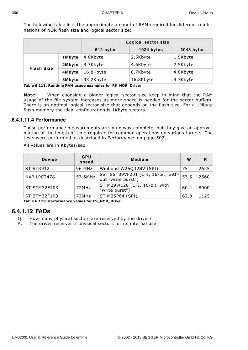
356 CHAPTER 6 Device drivers
The following table lists the approximate amount of RAM required for different combi-nations of NOR flash size and logical sector size:
Note: When choosing a bigger logical sector size keep in mind that the RAMusage of the file system increases as more space is needed for the sector buffers.There is an optimal logical sector size that depends on the flash size. For a 1Mbyteflash memory the ideal configuration is 1Kbyte sectors.
6.4.1.11.4 Performance
These performance measurements are in no way complete, but they give an approxi-mation of the length of time required for common operations on various targets. Thetests were performed as described in Performance on page 502.
All values are in Kbytes/sec
6.4.1.12 FAQsQ: How many physical sectors are reserved by the driver?A: The driver reserves 2 physical sectors for its internal use.
Logical sector size
512 bytes 1024 bytes 2048 bytes
Flash Size
1Mbyte 4.6Kbyte 2.5Kbyte 1.5Kbyte
2Mbyte 8.7Kbyte 4.6Kbyte 2.5Kbyte
4Mbyte 16.8Kbyte 8.7Kbyte 4.6Kbyte
8Mbyte 33.2Kbyte 16.8Kbyte 8.7KbyteTable 6.118: Runtime RAM usage examples for FS_NOR_Driver
DeviceCPU
speedMedium W R
ST STR912 96 MHz Winbond W25Q32BV (SPI) 75 2625
NXP LPC2478 57.6MHz SST SST39VF201 (CFI, 16-bit, with-out "write burst") 53.5 2560
ST STM32F103 72MHz ST M29W128 (CFI, 16-bit, with "write burst") 60.4 8000
ST STM32F103 72MHz ST M25P64 (SPI) 62.8 1125Table 6.119: Performance values for FS_NOR_Driver
UM02001 User & Reference Guide for emFile © 2002 - 2015 SEGGER Microcontroller GmbH & Co. KG
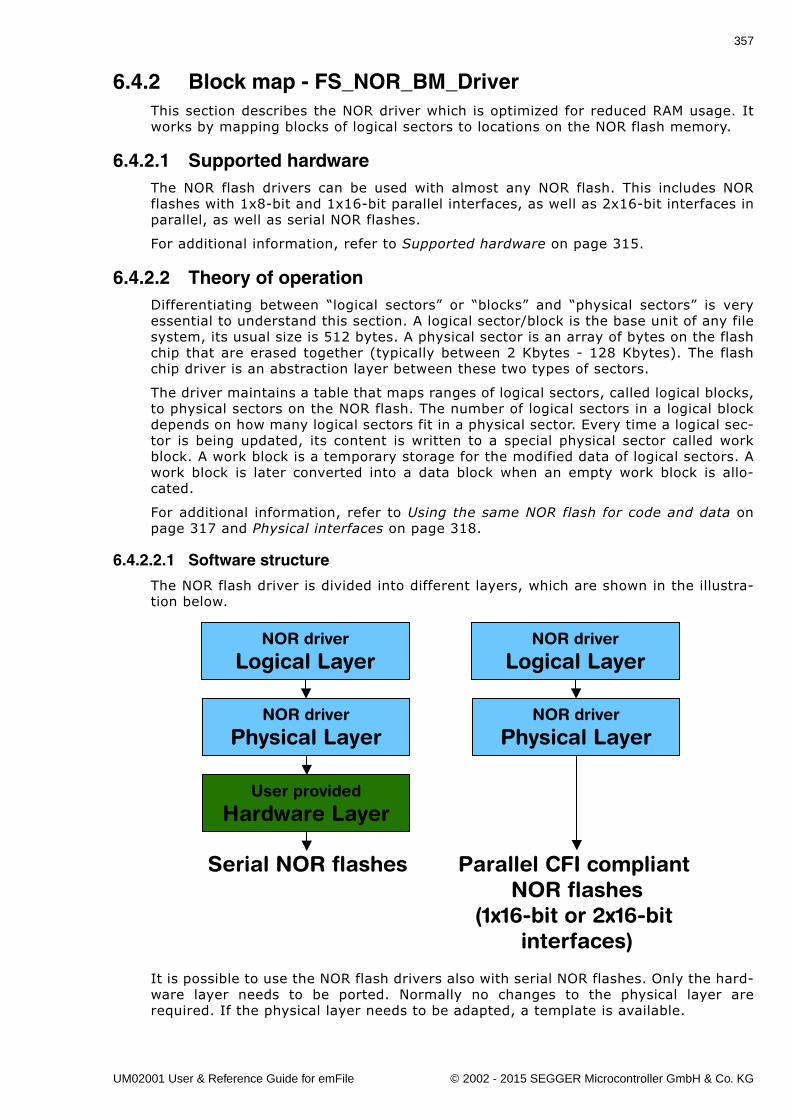
357
6.4.2 Block map - FS_NOR_BM_DriverThis section describes the NOR driver which is optimized for reduced RAM usage. Itworks by mapping blocks of logical sectors to locations on the NOR flash memory.
6.4.2.1 Supported hardwareThe NOR flash drivers can be used with almost any NOR flash. This includes NORflashes with 1x8-bit and 1x16-bit parallel interfaces, as well as 2x16-bit interfaces inparallel, as well as serial NOR flashes.
For additional information, refer to Supported hardware on page 315.
6.4.2.2 Theory of operationDifferentiating between �logical sectors� or �blocks� and �physical sectors� is veryessential to understand this section. A logical sector/block is the base unit of any filesystem, its usual size is 512 bytes. A physical sector is an array of bytes on the flashchip that are erased together (typically between 2 Kbytes - 128 Kbytes). The flashchip driver is an abstraction layer between these two types of sectors.
The driver maintains a table that maps ranges of logical sectors, called logical blocks,to physical sectors on the NOR flash. The number of logical sectors in a logical blockdepends on how many logical sectors fit in a physical sector. Every time a logical sec-tor is being updated, its content is written to a special physical sector called workblock. A work block is a temporary storage for the modified data of logical sectors. Awork block is later converted into a data block when an empty work block is allo-cated.
For additional information, refer to Using the same NOR flash for code and data onpage 317 and Physical interfaces on page 318.
6.4.2.2.1 Software structure
The NOR flash driver is divided into different layers, which are shown in the illustra-tion below.
It is possible to use the NOR flash drivers also with serial NOR flashes. Only the hard-ware layer needs to be ported. Normally no changes to the physical layer arerequired. If the physical layer needs to be adapted, a template is available.
NOR driver
Logical Layer
NOR driver
Physical Layer
User provided
Hardware Layer
NOR driver
Logical Layer
NOR driver
Physical Layer
Serial NOR flashes Parallel CFI compliantNOR flashes
(1x16-bit or 2x16-bit interfaces)
UM02001 User & Reference Guide for emFile © 2002 - 2015 SEGGER Microcontroller GmbH & Co. KG
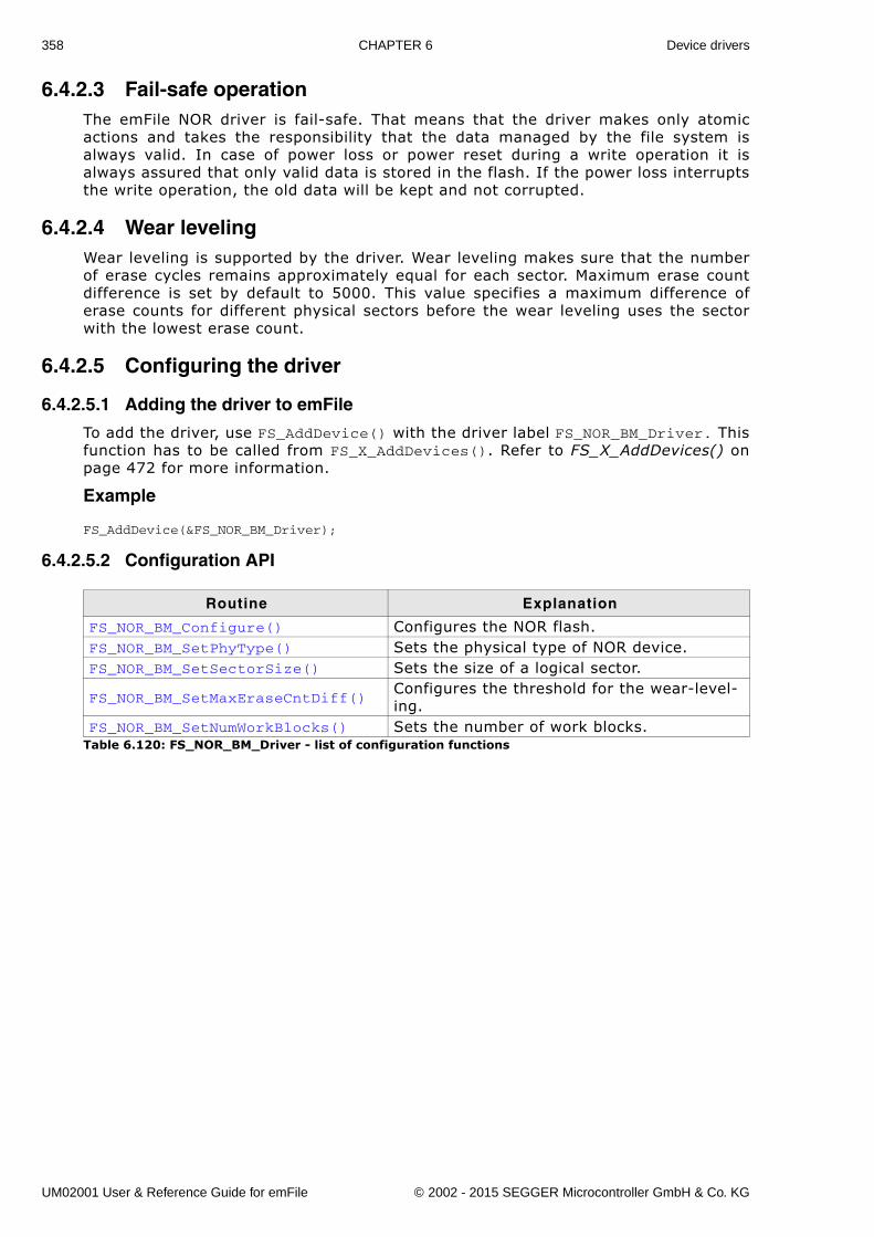
358 CHAPTER 6 Device drivers
6.4.2.3 Fail-safe operationThe emFile NOR driver is fail-safe. That means that the driver makes only atomicactions and takes the responsibility that the data managed by the file system isalways valid. In case of power loss or power reset during a write operation it isalways assured that only valid data is stored in the flash. If the power loss interruptsthe write operation, the old data will be kept and not corrupted.
6.4.2.4 Wear levelingWear leveling is supported by the driver. Wear leveling makes sure that the numberof erase cycles remains approximately equal for each sector. Maximum erase countdifference is set by default to 5000. This value specifies a maximum difference oferase counts for different physical sectors before the wear leveling uses the sectorwith the lowest erase count.
6.4.2.5 Configuring the driver
6.4.2.5.1 Adding the driver to emFile
To add the driver, use FS_AddDevice() with the driver label FS_NOR_BM_Driver. Thisfunction has to be called from FS_X_AddDevices(). Refer to FS_X_AddDevices() onpage 472 for more information.
Example
FS_AddDevice(&FS_NOR_BM_Driver);
6.4.2.5.2 Configuration API
Routine Explanation
FS_NOR_BM_Configure() Configures the NOR flash.FS_NOR_BM_SetPhyType() Sets the physical type of NOR device.FS_NOR_BM_SetSectorSize() Sets the size of a logical sector.
FS_NOR_BM_SetMaxEraseCntDiff()Configures the threshold for the wear-level-ing.
FS_NOR_BM_SetNumWorkBlocks() Sets the number of work blocks.Table 6.120: FS_NOR_BM_Driver - list of configuration functions
UM02001 User & Reference Guide for emFile © 2002 - 2015 SEGGER Microcontroller GmbH & Co. KG
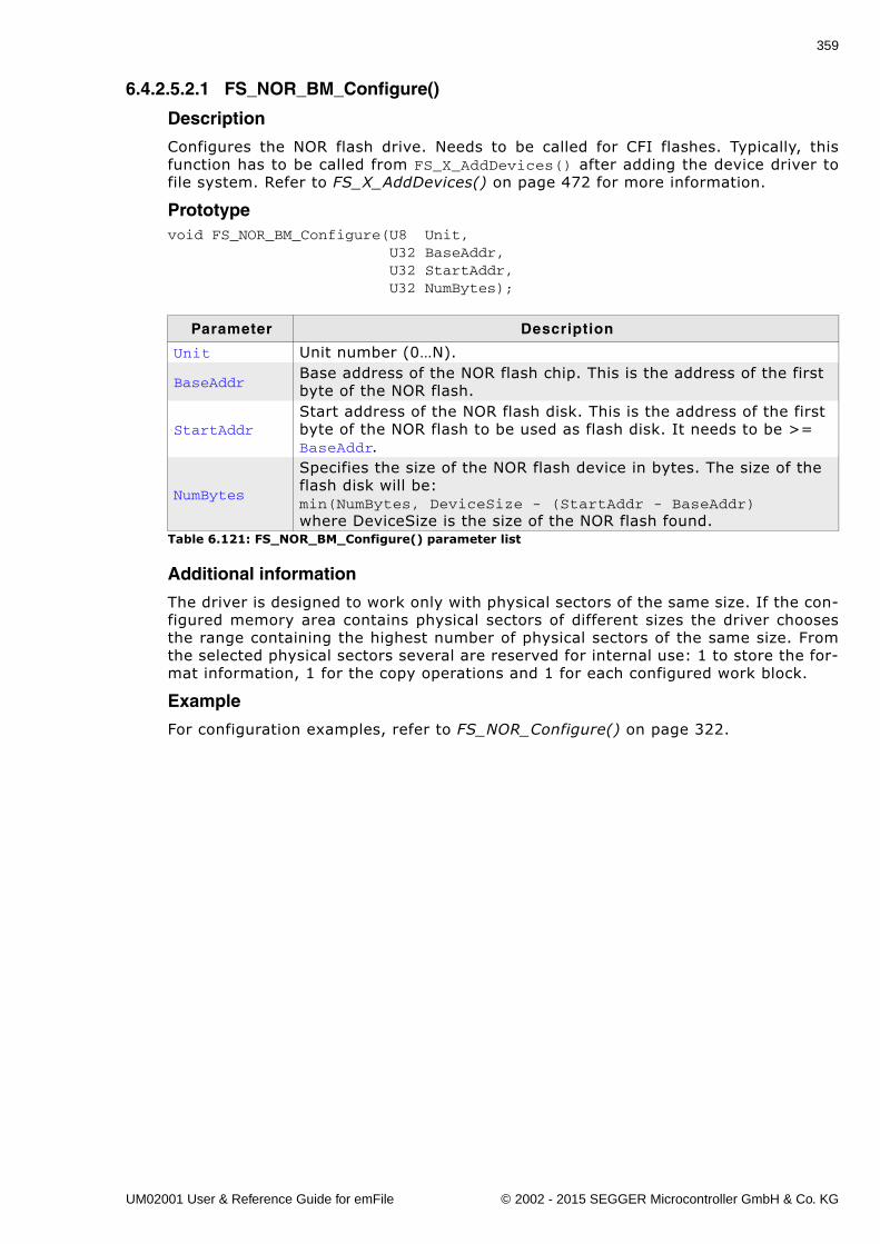
359
6.4.2.5.2.1 FS_NOR_BM_Configure()
Description
Configures the NOR flash drive. Needs to be called for CFI flashes. Typically, thisfunction has to be called from FS_X_AddDevices() after adding the device driver tofile system. Refer to FS_X_AddDevices() on page 472 for more information.
Prototypevoid FS_NOR_BM_Configure(U8 Unit, U32 BaseAddr, U32 StartAddr, U32 NumBytes);
Additional information
The driver is designed to work only with physical sectors of the same size. If the con-figured memory area contains physical sectors of different sizes the driver choosesthe range containing the highest number of physical sectors of the same size. Fromthe selected physical sectors several are reserved for internal use: 1 to store the for-mat information, 1 for the copy operations and 1 for each configured work block.
Example
For configuration examples, refer to FS_NOR_Configure() on page 322.
Parameter Description
Unit Unit number (0�N).
BaseAddrBase address of the NOR flash chip. This is the address of the first byte of the NOR flash.
StartAddrStart address of the NOR flash disk. This is the address of the first byte of the NOR flash to be used as flash disk. It needs to be >= BaseAddr.
NumBytes
Specifies the size of the NOR flash device in bytes. The size of the flash disk will be: min(NumBytes, DeviceSize - (StartAddr - BaseAddr) where DeviceSize is the size of the NOR flash found.
Table 6.121: FS_NOR_BM_Configure() parameter list
UM02001 User & Reference Guide for emFile © 2002 - 2015 SEGGER Microcontroller GmbH & Co. KG
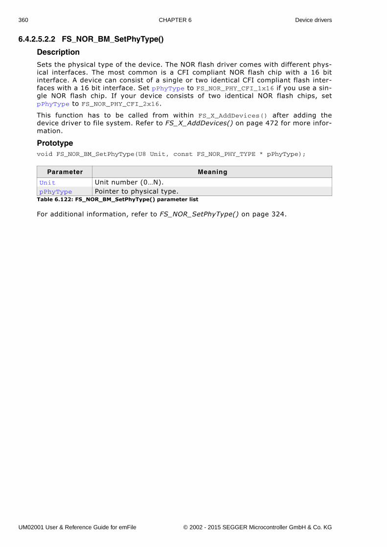
360 CHAPTER 6 Device drivers
6.4.2.5.2.2 FS_NOR_BM_SetPhyType()
Description
Sets the physical type of the device. The NOR flash driver comes with different phys-ical interfaces. The most common is a CFI compliant NOR flash chip with a 16 bitinterface. A device can consist of a single or two identical CFI compliant flash inter-faces with a 16 bit interface. Set pPhyType to FS_NOR_PHY_CFI_1x16 if you use a sin-gle NOR flash chip. If your device consists of two identical NOR flash chips, setpPhyType to FS_NOR_PHY_CFI_2x16.
This function has to be called from within FS_X_AddDevices() after adding thedevice driver to file system. Refer to FS_X_AddDevices() on page 472 for more infor-mation.
Prototypevoid FS_NOR_BM_SetPhyType(U8 Unit, const FS_NOR_PHY_TYPE * pPhyType);
For additional information, refer to FS_NOR_SetPhyType() on page 324.
Parameter Meaning
Unit Unit number (0�N).pPhyType Pointer to physical type.
Table 6.122: FS_NOR_BM_SetPhyType() parameter list
UM02001 User & Reference Guide for emFile © 2002 - 2015 SEGGER Microcontroller GmbH & Co. KG
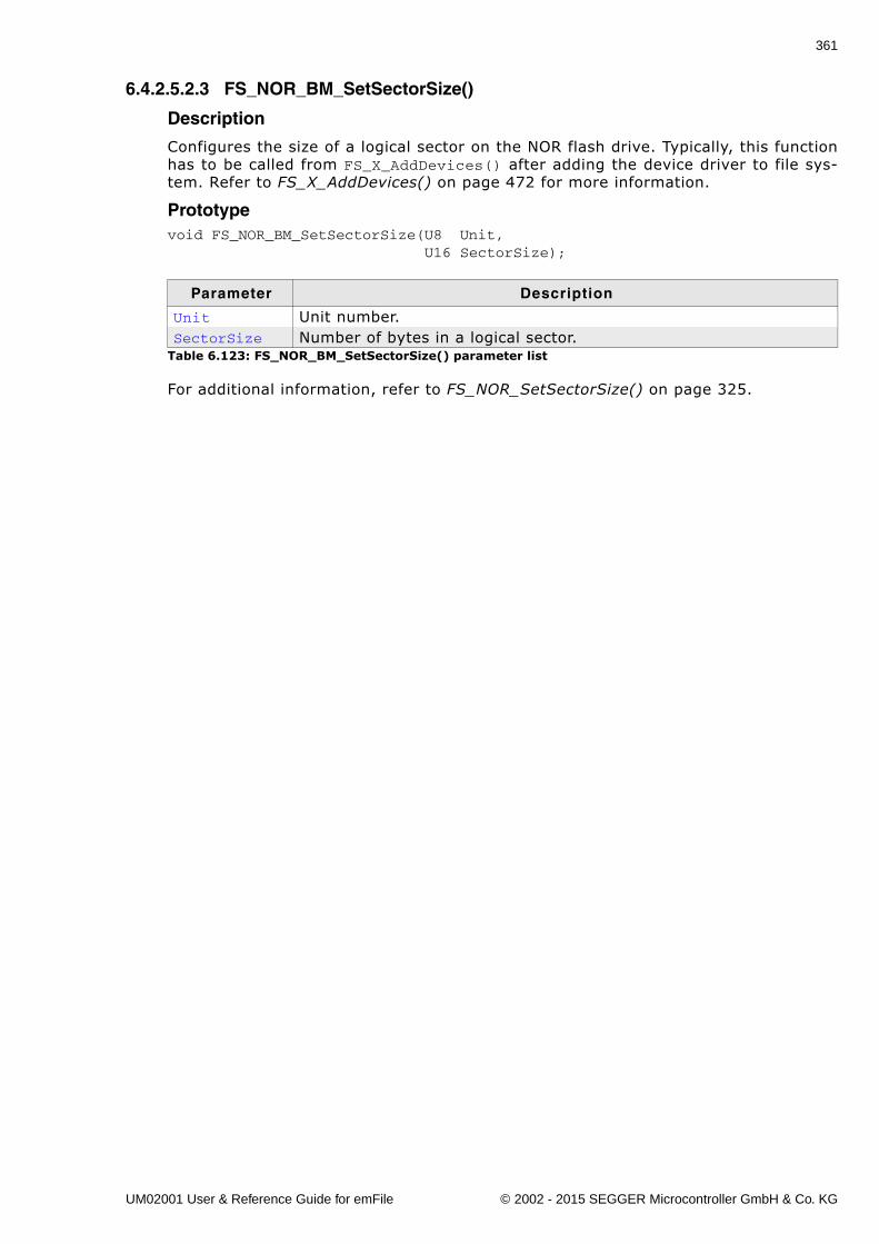
361
6.4.2.5.2.3 FS_NOR_BM_SetSectorSize()
Description
Configures the size of a logical sector on the NOR flash drive. Typically, this functionhas to be called from FS_X_AddDevices() after adding the device driver to file sys-tem. Refer to FS_X_AddDevices() on page 472 for more information.
Prototypevoid FS_NOR_BM_SetSectorSize(U8 Unit, U16 SectorSize);
For additional information, refer to FS_NOR_SetSectorSize() on page 325.
Parameter Description
Unit Unit number.SectorSize Number of bytes in a logical sector.
Table 6.123: FS_NOR_BM_SetSectorSize() parameter list
UM02001 User & Reference Guide for emFile © 2002 - 2015 SEGGER Microcontroller GmbH & Co. KG
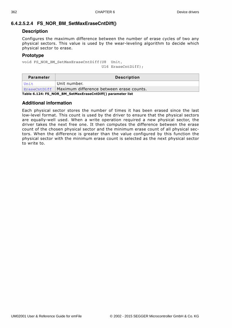
362 CHAPTER 6 Device drivers
6.4.2.5.2.4 FS_NOR_BM_SetMaxEraseCntDiff()
Description
Configures the maximum difference between the number of erase cycles of two anyphysical sectors. This value is used by the wear-leveling algorithm to decide whichphysical sector to erase.
Prototypevoid FS_NOR_BM_SetMaxEraseCntDiff(U8 Unit, U16 EraseCntDiff);
Additional information
Each physical sector stores the number of times it has been erased since the lastlow-level format. This count is used by the driver to ensure that the physical sectorsare equally-well used. When a write operation required a new physical sector, thedriver takes the next free one. It then computes the difference between the erasecount of the chosen physical sector and the minimum erase count of all physical sec-tors. When the difference is greater than the value configured by this function thephysical sector with the minimum erase count is selected as the next physical sectorto write to.
Parameter Description
Unit Unit number.EraseCntDiff Maximum difference between erase counts.
Table 6.124: FS_NOR_BM_SetMaxEraseCntDiff() parameter list
UM02001 User & Reference Guide for emFile © 2002 - 2015 SEGGER Microcontroller GmbH & Co. KG
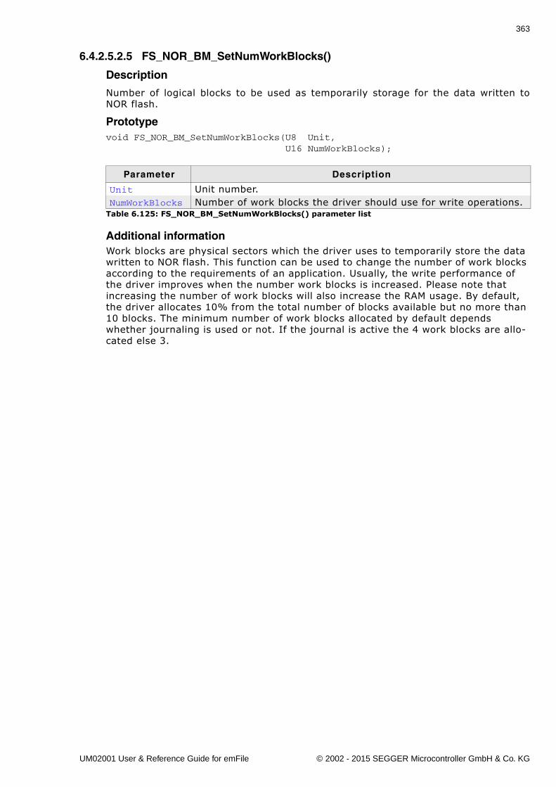
363
6.4.2.5.2.5 FS_NOR_BM_SetNumWorkBlocks()
Description
Number of logical blocks to be used as temporarily storage for the data written toNOR flash.
Prototypevoid FS_NOR_BM_SetNumWorkBlocks(U8 Unit, U16 NumWorkBlocks);
Additional informationWork blocks are physical sectors which the driver uses to temporarily store the data written to NOR flash. This function can be used to change the number of work blocks according to the requirements of an application. Usually, the write performance of the driver improves when the number work blocks is increased. Please note that increasing the number of work blocks will also increase the RAM usage. By default, the driver allocates 10% from the total number of blocks available but no more than 10 blocks. The minimum number of work blocks allocated by default depends whether journaling is used or not. If the journal is active the 4 work blocks are allo-cated else 3.
Parameter Description
Unit Unit number.NumWorkBlocks Number of work blocks the driver should use for write operations.
Table 6.125: FS_NOR_BM_SetNumWorkBlocks() parameter list
UM02001 User & Reference Guide for emFile © 2002 - 2015 SEGGER Microcontroller GmbH & Co. KG
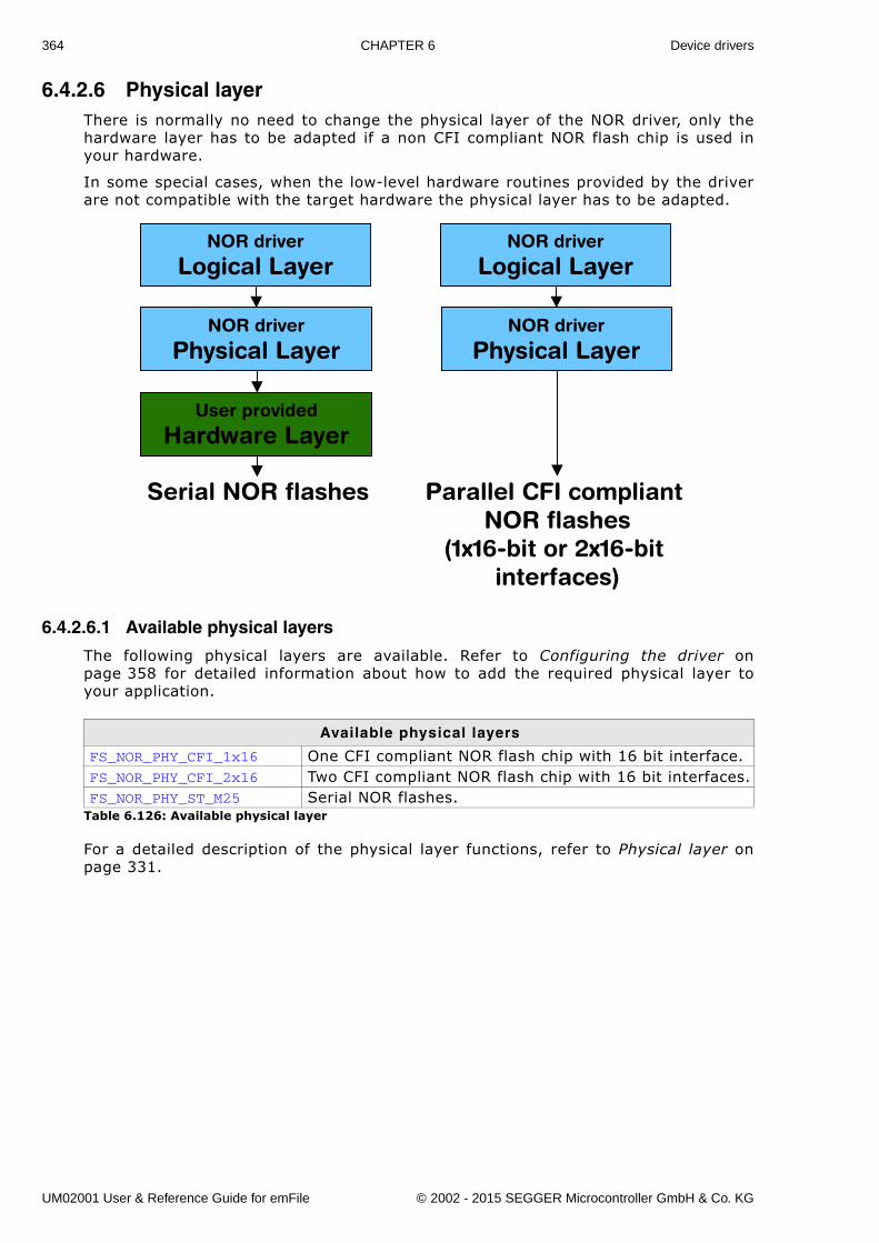
364 CHAPTER 6 Device drivers
6.4.2.6 Physical layerThere is normally no need to change the physical layer of the NOR driver, only thehardware layer has to be adapted if a non CFI compliant NOR flash chip is used inyour hardware.
In some special cases, when the low-level hardware routines provided by the driverare not compatible with the target hardware the physical layer has to be adapted.
6.4.2.6.1 Available physical layers
The following physical layers are available. Refer to Configuring the driver onpage 358 for detailed information about how to add the required physical layer toyour application.
For a detailed description of the physical layer functions, refer to Physical layer onpage 331.
Available physical layers
FS_NOR_PHY_CFI_1x16 One CFI compliant NOR flash chip with 16 bit interface.FS_NOR_PHY_CFI_2x16 Two CFI compliant NOR flash chip with 16 bit interfaces.FS_NOR_PHY_ST_M25 Serial NOR flashes.
Table 6.126: Available physical layer
NOR driver
Logical Layer
NOR driver
Physical Layer
User provided
Hardware Layer
NOR driver
Logical Layer
NOR driver
Physical Layer
Serial NOR flashes Parallel CFI compliantNOR flashes
(1x16-bit or 2x16-bit interfaces)
UM02001 User & Reference Guide for emFile © 2002 - 2015 SEGGER Microcontroller GmbH & Co. KG
365
6.4.2.7 Hardware functionsDepending on the used NOR flash type and the corresponding physical layer, differenthardware functions are required. CFI compliant NOR flashes do not need any hard-ware function, refer to Hardware functions on page 340 for detailed informationabout the hardware functions required by the physical layer for serial NOR flashes.
6.4.2.8 Additional informationLow-level format
Before using the NOR flash as storage device. A low-level format has to be per-formed. Refer to FS_FormatLow() on page 113 and FS_FormatLLIfRequired() onpage 112 for detailed information about low-level formatting.
Further reading
For more technical details about CFI compliant flash memory, check the documentsand specifications that are available free of charge:
� Common Flash Interface (CFI) and Command SetsIntel - Application Note 646 - April 2000
� Common Flash Memory Interface SpecificationAMD - Revision 2.0 - December 1, 2001
6.4.2.9 Additional driver functions
Routine Explanation
FS_NOR_BM_GetDiskInfo() Returns information about NOR flash.FS_NOR_BM_ReadOff() Reads data from NOR flash memory.
Table 6.127: FS_NOR_BM_Driver - list of configuration functions
UM02001 User & Reference Guide for emFile © 2002 - 2015 SEGGER Microcontroller GmbH & Co. KG
366 CHAPTER 6 Device drivers
6.4.2.9.1 FS_NOR_BM_GetDiskInfo()
Description
Returns information about the NOR flash.
Prototypevoid FS_NOR_BM_GetDiskInfo(U8 Unit, FS_NOR_BM_DISK_INFO * pDiskInfo);
Additional information
Refer to Structure FS_NOR_BM_DISK_INFO on page 369 for more information aboutthe structure elements.
Parameter Description
Unit Unit number.pDiskInfo Pointer to a structure of type FS_NOR_DISK_INFO.
Table 6.128: FS_NOR_BM_GetDiskInfo() parameter list
UM02001 User & Reference Guide for emFile © 2002 - 2015 SEGGER Microcontroller GmbH & Co. KG
367
6.4.2.9.2 FS_NOR_BM_GetSectorInfo()
Description
Returns info about a particular physical sector.
Prototypevoid FS_NOR_GetSectorInfo(U8 Unit, U32 PhysSectorIndex, FS_NOR_BM_SECTOR_INFO * pSectorInfo);
Additional information
Refer to FS_NOR_SECTOR_INFO on page 354 for more information about the struc-ture elements.
Parameter Description
Unit Unit number.PhysSectorIndex Index of physical sector.pDiskInfo Pointer to a structure of type FS_NOR_BM_DISK_INFO.
Table 6.129: FS_NOR_BM_GetSectorInfo() parameter list
UM02001 User & Reference Guide for emFile © 2002 - 2015 SEGGER Microcontroller GmbH & Co. KG
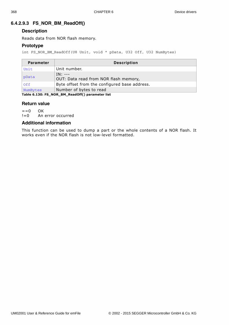
368 CHAPTER 6 Device drivers
6.4.2.9.3 FS_NOR_BM_ReadOff()
Description
Reads data from NOR flash memory.
Prototypeint FS_NOR_BM_ReadOff(U8 Unit, void * pData, U32 Off, U32 NumBytes)
Return value
==0 OK!=0 An error occurred
Additional information
This function can be used to dump a part or the whole contents of a NOR flash. Itworks even if the NOR flash is not low-level formatted.
Parameter Description
Unit Unit number.
pDataIN: ---OUT: Data read from NOR flash memory,
Off Byte offset from the configured base address.NumBytes Number of bytes to read
Table 6.130: FS_NOR_BM_ReadOff() parameter list
UM02001 User & Reference Guide for emFile © 2002 - 2015 SEGGER Microcontroller GmbH & Co. KG
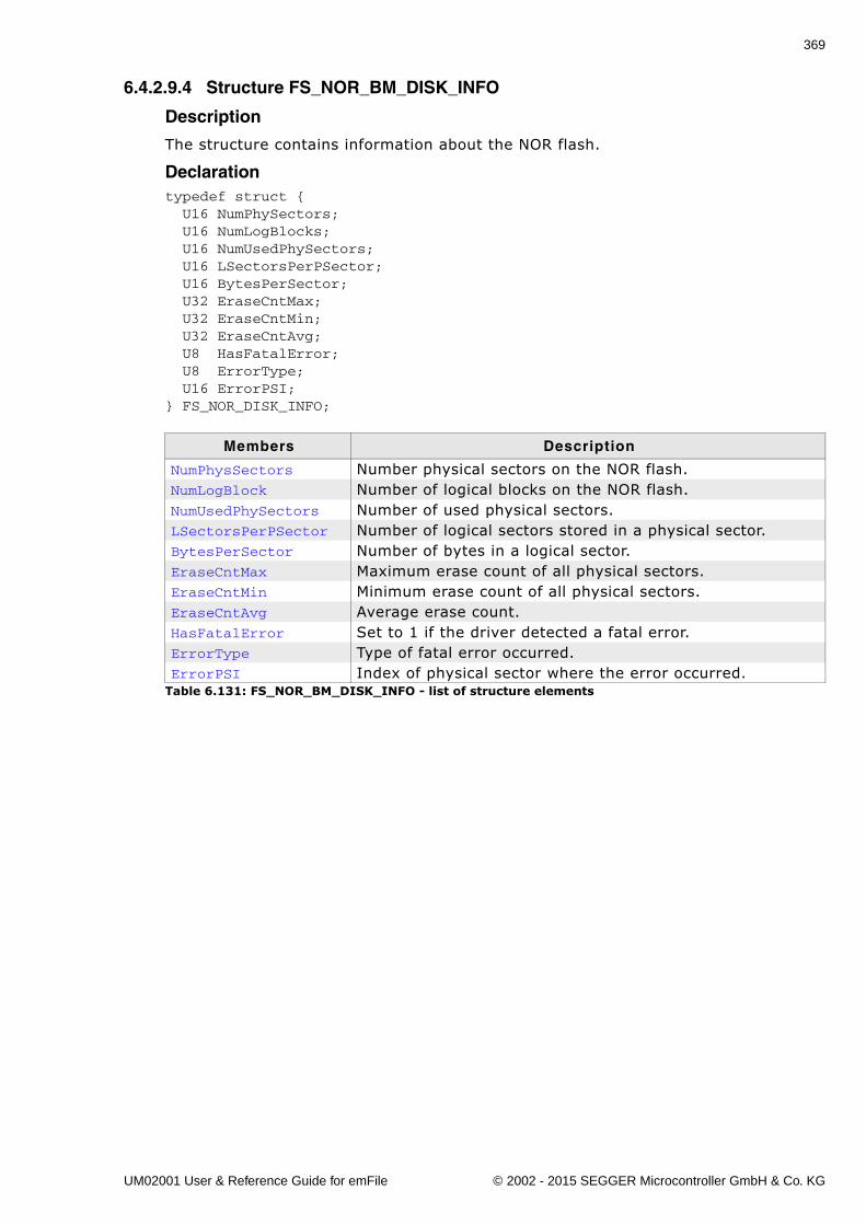
369
6.4.2.9.4 Structure FS_NOR_BM_DISK_INFO
Description
The structure contains information about the NOR flash.
Declarationtypedef struct { U16 NumPhySectors; U16 NumLogBlocks; U16 NumUsedPhySectors; U16 LSectorsPerPSector; U16 BytesPerSector; U32 EraseCntMax; U32 EraseCntMin; U32 EraseCntAvg; U8 HasFatalError; U8 ErrorType; U16 ErrorPSI;} FS_NOR_DISK_INFO;
Members Description
NumPhysSectors Number physical sectors on the NOR flash.NumLogBlock Number of logical blocks on the NOR flash.NumUsedPhySectors Number of used physical sectors.LSectorsPerPSector Number of logical sectors stored in a physical sector.BytesPerSector Number of bytes in a logical sector.EraseCntMax Maximum erase count of all physical sectors.EraseCntMin Minimum erase count of all physical sectors.EraseCntAvg Average erase count.HasFatalError Set to 1 if the driver detected a fatal error.ErrorType Type of fatal error occurred.ErrorPSI Index of physical sector where the error occurred.
Table 6.131: FS_NOR_BM_DISK_INFO - list of structure elements
UM02001 User & Reference Guide for emFile © 2002 - 2015 SEGGER Microcontroller GmbH & Co. KG
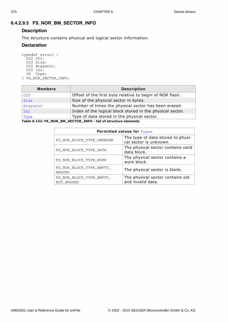
370 CHAPTER 6 Device drivers
6.4.2.9.5 FS_NOR_BM_SECTOR_INFO
Description
The structure contains physical and logical sector information.
Declaration
typedef struct { U32 Off; U32 Size; U32 EraseCnt; U16 lbi; U8 Type;} FS_NOR_SECTOR_INFO;
Members Description
Off Offset of the first byte relative to begin of NOR flash.Size Size of the physical sector in bytes.EraseCnt Number of times the physical sector has been erased.lbi Index of the logical block stored in the physical sector.Type Type of data stored in the physical sector.
Table 6.132: FS_NOR_BM_SECTOR_INFO - list of structure elements
Permitted values for Types
FS_NOR_BLOCK_TYPE_UNKNOWNThe type of data stored to physi-cal sector is unknown.
FS_NOR_BLOCK_TYPE_DATAThe physical sector contains valid data block.
FS_NOR_BLOCK_TYPE_WORKThe physical sector contains a work block.
FS_NOR_BLOCK_TYPE_EMPTY_ERASED
The physical sector is blank.
FS_NOR_BLOCK_TYPE_EMPTY_NOT_ERASED
The physical sector contains old and invalid data.
UM02001 User & Reference Guide for emFile © 2002 - 2015 SEGGER Microcontroller GmbH & Co. KG
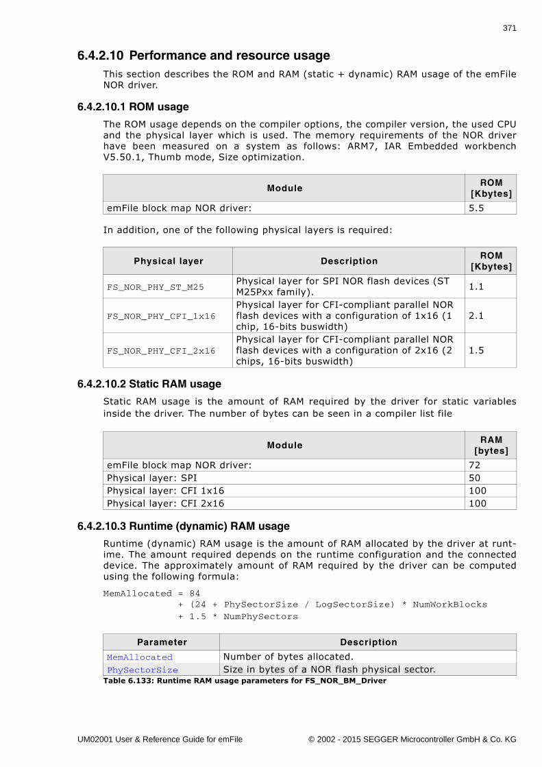
371
6.4.2.10 Performance and resource usageThis section describes the ROM and RAM (static + dynamic) RAM usage of the emFileNOR driver.
6.4.2.10.1 ROM usage
The ROM usage depends on the compiler options, the compiler version, the used CPUand the physical layer which is used. The memory requirements of the NOR driverhave been measured on a system as follows: ARM7, IAR Embedded workbenchV5.50.1, Thumb mode, Size optimization.
In addition, one of the following physical layers is required:
6.4.2.10.2 Static RAM usage
Static RAM usage is the amount of RAM required by the driver for static variablesinside the driver. The number of bytes can be seen in a compiler list file
6.4.2.10.3 Runtime (dynamic) RAM usage
Runtime (dynamic) RAM usage is the amount of RAM allocated by the driver at runt-ime. The amount required depends on the runtime configuration and the connecteddevice. The approximately amount of RAM required by the driver can be computedusing the following formula:
MemAllocated = 84 + (24 + PhySectorSize / LogSectorSize) * NumWorkBlocks
+ 1.5 * NumPhySectors
ModuleROM
[Kbytes]
emFile block map NOR driver: 5.5
Physical layer DescriptionROM
[Kbytes]
FS_NOR_PHY_ST_M25Physical layer for SPI NOR flash devices (ST M25Pxx family). 1.1
FS_NOR_PHY_CFI_1x16Physical layer for CFI-compliant parallel NOR flash devices with a configuration of 1x16 (1 chip, 16-bits buswidth)
2.1
FS_NOR_PHY_CFI_2x16Physical layer for CFI-compliant parallel NOR flash devices with a configuration of 2x16 (2 chips, 16-bits buswidth)
1.5
ModuleRAM
[bytes]
emFile block map NOR driver: 72Physical layer: SPI 50Physical layer: CFI 1x16 100Physical layer: CFI 2x16 100
Parameter Description
MemAllocated Number of bytes allocated.PhySectorSize Size in bytes of a NOR flash physical sector.
Table 6.133: Runtime RAM usage parameters for FS_NOR_BM_Driver
UM02001 User & Reference Guide for emFile © 2002 - 2015 SEGGER Microcontroller GmbH & Co. KG
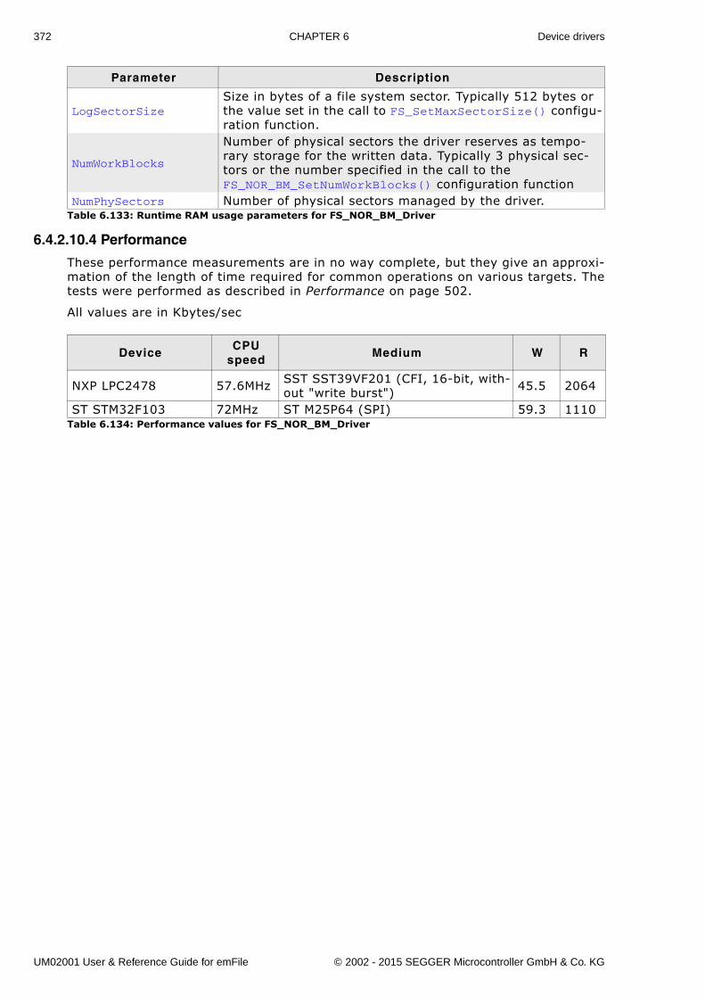
372 CHAPTER 6 Device drivers
6.4.2.10.4 Performance
These performance measurements are in no way complete, but they give an approxi-mation of the length of time required for common operations on various targets. Thetests were performed as described in Performance on page 502.
All values are in Kbytes/sec
LogSectorSizeSize in bytes of a file system sector. Typically 512 bytes or the value set in the call to FS_SetMaxSectorSize() configu-ration function.
NumWorkBlocks
Number of physical sectors the driver reserves as tempo-rary storage for the written data. Typically 3 physical sec-tors or the number specified in the call to the FS_NOR_BM_SetNumWorkBlocks() configuration function
NumPhySectors Number of physical sectors managed by the driver.
DeviceCPU
speedMedium W R
NXP LPC2478 57.6MHz SST SST39VF201 (CFI, 16-bit, with-out "write burst") 45.5 2064
ST STM32F103 72MHz ST M25P64 (SPI) 59.3 1110Table 6.134: Performance values for FS_NOR_BM_Driver
Parameter Description
Table 6.133: Runtime RAM usage parameters for FS_NOR_BM_Driver
UM02001 User & Reference Guide for emFile © 2002 - 2015 SEGGER Microcontroller GmbH & Co. KG
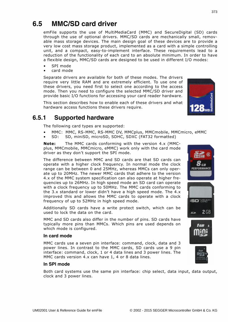
373
6.5 MMC/SD card driveremFile supports the use of MultiMediaCard (MMC) and SecureDigital (SD) cardsthrough the use of optional drivers. MMC/SD cards are mechanically small, remov-able mass storage devices. The main design goal of these devices are to provide avery low cost mass storage product, implemented as a card with a simple controllingunit, and a compact, easy-to-implement interface. These requirements lead to areduction of the functionality of each card to an absolute minimum. In order to havea flexible design, MMC/SD cards are designed to be used in different I/O modes:
� SPI mode� card mode
Separate drivers are available for both of these modes. The driversrequire very little RAM and are extremely efficient. To use one ofthese drivers, you need first to select one according to the accessmode. Then you need to configure the selected MMC/SD driver andprovide basic I/O functions for accessing your card reader hardware.
This section describes how to enable each of these drivers and whathardware access functions these drivers require.
6.5.1 Supported hardwareThe following card types are supported:
� MMC: MMC, RS-MMC, RS-MMC DV, MMCplus, MMCmobile, MMCmicro, eMMC� SD: SD, miniSD, microSD, SDHC, SDXC (FAT32 formatted)
Note: The MMC cards conforming with the version 4.x (MMC-plus, MMCmobile, MMCmicro, eMMC) work only with the card modedriver as they don�t support the SPI mode.
The difference between MMC and SD cards are that SD cards canoperate with a higher clock frequency. In normal mode the clockrange can be between 0 and 25MHz, whereas MMCs can only oper-ate up to 20MHz. The newer MMC cards that adhere to the version4.x of the MMC system specification can also operate at higher fre-quencies up to 26MHz. In high speed mode an SD card can operatewith a clock frequency up to 50MHz. The MMC cards conforming tothe 3.x standard or lower didn�t have a high speed mode. The 4.ximproved this and allows the MMC cards to operate with a clockfrequency of up to 52MHz in high speed mode.
Additionally SD cards have a write protect switch, which can beused to lock the data on the card.
MMC and SD cards also differ in the number of pins. SD cards havetypically more pins than MMCs. Which pins are used depends onwhich mode is configured.
In card mode
MMC cards use a seven pin interface: command, clock, data and 3power lines. In contrast to the MMC cards, SD cards use a 9 pininterface: command, clock, 1 or 4 data lines and 3 power lines. TheMMC cards version 4.x can have 1, 4 or 8 data lines.
In SPI mode
Both card systems use the same pin interface: chip select, data input, data output,clock and 3 power lines.
UM02001 User & Reference Guide for emFile © 2002 - 2015 SEGGER Microcontroller GmbH & Co. KG
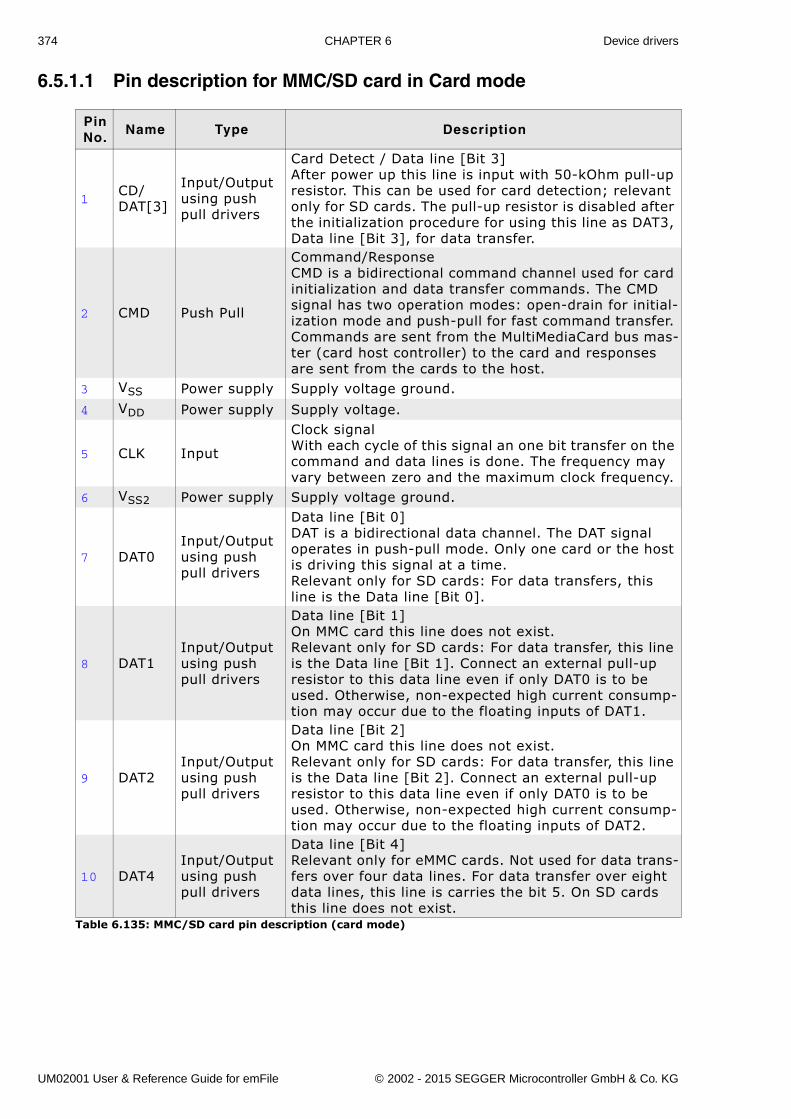
374 CHAPTER 6 Device drivers
6.5.1.1 Pin description for MMC/SD card in Card mode
Pin No.
Name Type Description
1CD/DAT[3]
Input/Outputusing push pull drivers
Card Detect / Data line [Bit 3]After power up this line is input with 50-kOhm pull-up resistor. This can be used for card detection; relevant only for SD cards. The pull-up resistor is disabled after the initialization procedure for using this line as DAT3, Data line [Bit 3], for data transfer.
2 CMD Push Pull
Command/ResponseCMD is a bidirectional command channel used for card initialization and data transfer commands. The CMD signal has two operation modes: open-drain for initial-ization mode and push-pull for fast command transfer. Commands are sent from the MultiMediaCard bus mas-ter (card host controller) to the card and responses are sent from the cards to the host.
3 VSS Power supply Supply voltage ground.
4 VDD Power supply Supply voltage.
5 CLK Input
Clock signalWith each cycle of this signal an one bit transfer on the command and data lines is done. The frequency may vary between zero and the maximum clock frequency.
6 VSS2 Power supply Supply voltage ground.
7 DAT0Input/Outputusing push pull drivers
Data line [Bit 0]DAT is a bidirectional data channel. The DAT signal operates in push-pull mode. Only one card or the host is driving this signal at a time.Relevant only for SD cards: For data transfers, this line is the Data line [Bit 0].
8 DAT1Input/Outputusing push pull drivers
Data line [Bit 1]On MMC card this line does not exist.Relevant only for SD cards: For data transfer, this line is the Data line [Bit 1]. Connect an external pull-up resistor to this data line even if only DAT0 is to be used. Otherwise, non-expected high current consump-tion may occur due to the floating inputs of DAT1.
9 DAT2Input/Outputusing push pull drivers
Data line [Bit 2]On MMC card this line does not exist.Relevant only for SD cards: For data transfer, this line is the Data line [Bit 2]. Connect an external pull-up resistor to this data line even if only DAT0 is to be used. Otherwise, non-expected high current consump-tion may occur due to the floating inputs of DAT2.
10 DAT4Input/Outputusing push pull drivers
Data line [Bit 4]Relevant only for eMMC cards. Not used for data trans-fers over four data lines. For data transfer over eight data lines, this line is carries the bit 5. On SD cards this line does not exist.
Table 6.135: MMC/SD card pin description (card mode)
UM02001 User & Reference Guide for emFile © 2002 - 2015 SEGGER Microcontroller GmbH & Co. KG
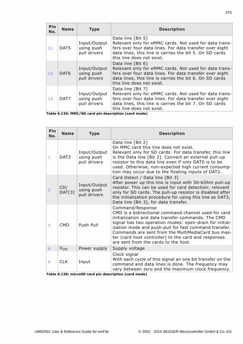
375
11 DAT5Input/Outputusing push pull drivers
Data line [Bit 5]Relevant only for eMMC cards. Not used for data trans-fers over four data lines. For data transfer over eight data lines, this line is carries the bit 5. On SD cards this line does not exist.
12 DAT6Input/Outputusing push pull drivers
Data line [Bit 6]Relevant only for eMMC cards. Not used for data trans-fers over four data lines. For data transfer over eight data lines, this line is carries the bit 6. On SD cards this line does not exist.
13 DAT7Input/Outputusing push pull drivers
Data line [Bit 7]Relevant only for eMMC cards. Not used for data trans-fers over four data lines. For data transfer over eight data lines, this line is carries the bit 7. On SD cards this line does not exist.
Pin No.
Name Type Description
1 DAT2Input/Outputusing push pull drivers
Data line [Bit 2]On MMC card this line does not exist.Relevant only for SD cards: For data transfer, this line is the Data line [Bit 2]. Connect an external pull-up resistor to this data line even if only DAT0 is to be used. Otherwise, non-expected high current consump-tion may occur due to the floating inputs of DAT2.
2CD/DAT[3]
Input/Outputusing push pull drivers
Card Detect / Data line [Bit 3]After power up this line is input with 50-kOhm pull-up resistor. This can be used for card detection; relevant only for SD cards. The pull-up resistor is disabled after the initialization procedure for using this line as DAT3, Data line [Bit 3], for data transfer.
3 CMD Push Pull
Command/ResponseCMD is a bidirectional command channel used for card initialization and data transfer commands. The CMD signal has two operation modes: open-drain for initial-ization mode and push-pull for fast command transfer. Commands are sent from the MultiMediaCard bus mas-ter (card host controller) to the card and responses are sent from the cards to the host.
4 VDD Power supply Supply voltage
5 CLK Input
Clock signalWith each cycle of this signal an one bit transfer on the command and data lines is done. The frequency may vary between zero and the maximum clock frequency.
Table 6.136: microSD card pin description (card mode)
Pin No.
Name Type Description
Table 6.135: MMC/SD card pin description (card mode)
UM02001 User & Reference Guide for emFile © 2002 - 2015 SEGGER Microcontroller GmbH & Co. KG
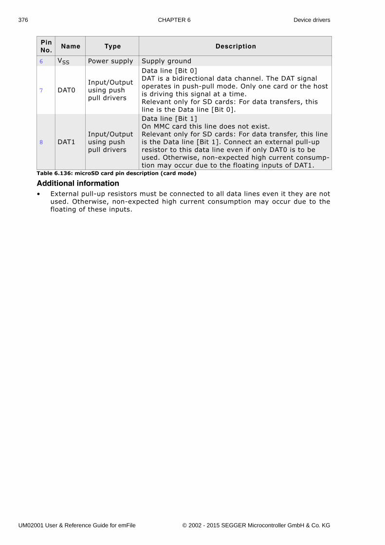
376 CHAPTER 6 Device drivers
Additional information� External pull-up resistors must be connected to all data lines even it they are not
used. Otherwise, non-expected high current consumption may occur due to thefloating of these inputs.
6 VSS Power supply Supply ground
7 DAT0Input/Outputusing push pull drivers
Data line [Bit 0]DAT is a bidirectional data channel. The DAT signal operates in push-pull mode. Only one card or the host is driving this signal at a time.Relevant only for SD cards: For data transfers, this line is the Data line [Bit 0].
8 DAT1Input/Outputusing push pull drivers
Data line [Bit 1]On MMC card this line does not exist.Relevant only for SD cards: For data transfer, this line is the Data line [Bit 1]. Connect an external pull-up resistor to this data line even if only DAT0 is to be used. Otherwise, non-expected high current consump-tion may occur due to the floating inputs of DAT1.
Pin No.
Name Type Description
Table 6.136: microSD card pin description (card mode)
UM02001 User & Reference Guide for emFile © 2002 - 2015 SEGGER Microcontroller GmbH & Co. KG
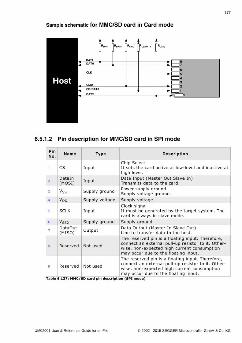
377
Sample schematic for MMC/SD card in Card mode
6.5.1.2 Pin description for MMC/SD card in SPI mode
Pin No.
Name Type Description
1 CS InputChip SelectIt sets the card active at low-level and inactive at high level.
2DataIn(MOSI) Input Data Input (Master Out Slave In)
Transmits data to the card.
3 VSS Supply ground Power supply groundSupply voltage ground.
4 VDD Supply voltage Supply voltage
5 SCLK InputClock signalIt must be generated by the target system. The card is always in slave mode.
6 VSS2 Supply ground Supply ground
7DataOut(MISO) Output Data Output (Master In Slave Out)
Line to transfer data to the host.
8 Reserved Not used
The reserved pin is a floating input. Therefore, connect an external pull-up resistor to it. Other-wise, non-expected high current consumption may occur due to the floating input.
9 Reserved Not used
The reserved pin is a floating input. Therefore, connect an external pull-up resistor to it. Other-wise, non-expected high current consumption may occur due to the floating input.
Table 6.137: MMC/SD card pin description (SPI mode)
Host
7
654321
9
8
CMD
CLK
CD/DAT3
DAT0DAT1
DAT2
RDAT1 RDAT0 RCMD RCD/DAT3 RDAT2
UM02001 User & Reference Guide for emFile © 2002 - 2015 SEGGER Microcontroller GmbH & Co. KG
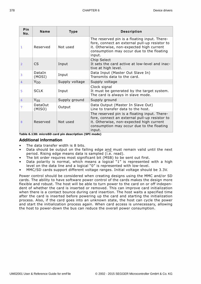
378 CHAPTER 6 Device drivers
Additional information� The data transfer width is 8 bits.� Data should be output on the falling edge and must remain valid until the next
period. Rising edge means data is sampled (i.e. read).� The bit order requires most significant bit (MSB) to be sent out first. � Data polarity is normal, which means a logical �1� is represented with a high
level on the data line and a logical �0� is represented with low-level.� MMC/SD cards support different voltage ranges. Initial voltage should be 3.3V.
Power control should be considered when creating designs using the MMC and/or SDcards. The ability to have software power control of the cards makes the design moreflexible and robust. The host will be able to turn power to the card on or off indepen-dent of whether the card is inserted or removed. This can improve card initializationwhen there is a contact bounce during card insertion. The host waits a specified timeafter the card is inserted before powering up the card and starting the initializationprocess. Also, if the card goes into an unknown state, the host can cycle the powerand start the initialization process again. When card access is unnecessary, allowingthe host to power-down the bus can reduce the overall power consumption.
Pin No.
Name Type Description
1 Reserved Not used
The reserved pin is a floating input. There-fore, connect an external pull-up resistor to it. Otherwise, non-expected high current consumption may occur due to the floating input.
2 CS InputChip SelectIt sets the card active at low-level and inac-tive at high level.
3DataIn (MOSI) Input Data Input (Master Out Slave In)
Transmits data to the card.4 VDD Supply voltage Supply voltage
5 SCLK InputClock signalIt must be generated by the target system. The card is always in slave mode.
6 VSS Supply ground Supply ground
7DataOut (MISO) Output Data Output (Master In Slave Out)
Line to transfer data to the host.
8 Reserved Not used
The reserved pin is a floating input. There-fore, connect an external pull-up resistor to it. Otherwise, non-expected high current consumption may occur due to the floating input.
Table 6.138: microSD card pin description (SPI mode)
UM02001 User & Reference Guide for emFile © 2002 - 2015 SEGGER Microcontroller GmbH & Co. KG
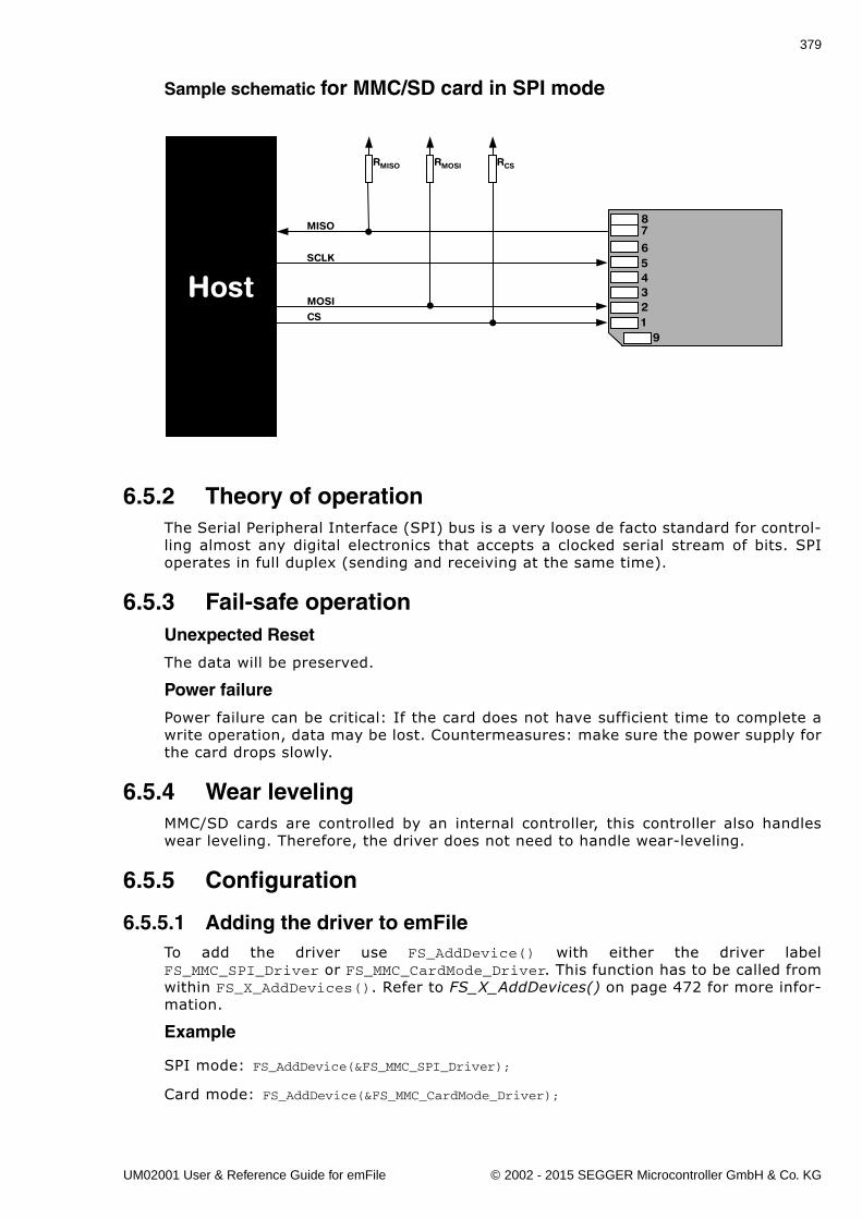
379
Sample schematic for MMC/SD card in SPI mode
6.5.2 Theory of operationThe Serial Peripheral Interface (SPI) bus is a very loose de facto standard for control-ling almost any digital electronics that accepts a clocked serial stream of bits. SPIoperates in full duplex (sending and receiving at the same time).
6.5.3 Fail-safe operationUnexpected Reset
The data will be preserved.
Power failure
Power failure can be critical: If the card does not have sufficient time to complete awrite operation, data may be lost. Countermeasures: make sure the power supply forthe card drops slowly.
6.5.4 Wear levelingMMC/SD cards are controlled by an internal controller, this controller also handleswear leveling. Therefore, the driver does not need to handle wear-leveling.
6.5.5 Configuration
6.5.5.1 Adding the driver to emFileTo add the driver use FS_AddDevice() with either the driver labelFS_MMC_SPI_Driver or FS_MMC_CardMode_Driver. This function has to be called fromwithin FS_X_AddDevices(). Refer to FS_X_AddDevices() on page 472 for more infor-mation.
Example
SPI mode: FS_AddDevice(&FS_MMC_SPI_Driver);
Card mode: FS_AddDevice(&FS_MMC_CardMode_Driver);
Host
7
654321
9
8
MOSI
SCLK
CS
MISO
RMISO RMOSI RCS
UM02001 User & Reference Guide for emFile © 2002 - 2015 SEGGER Microcontroller GmbH & Co. KG
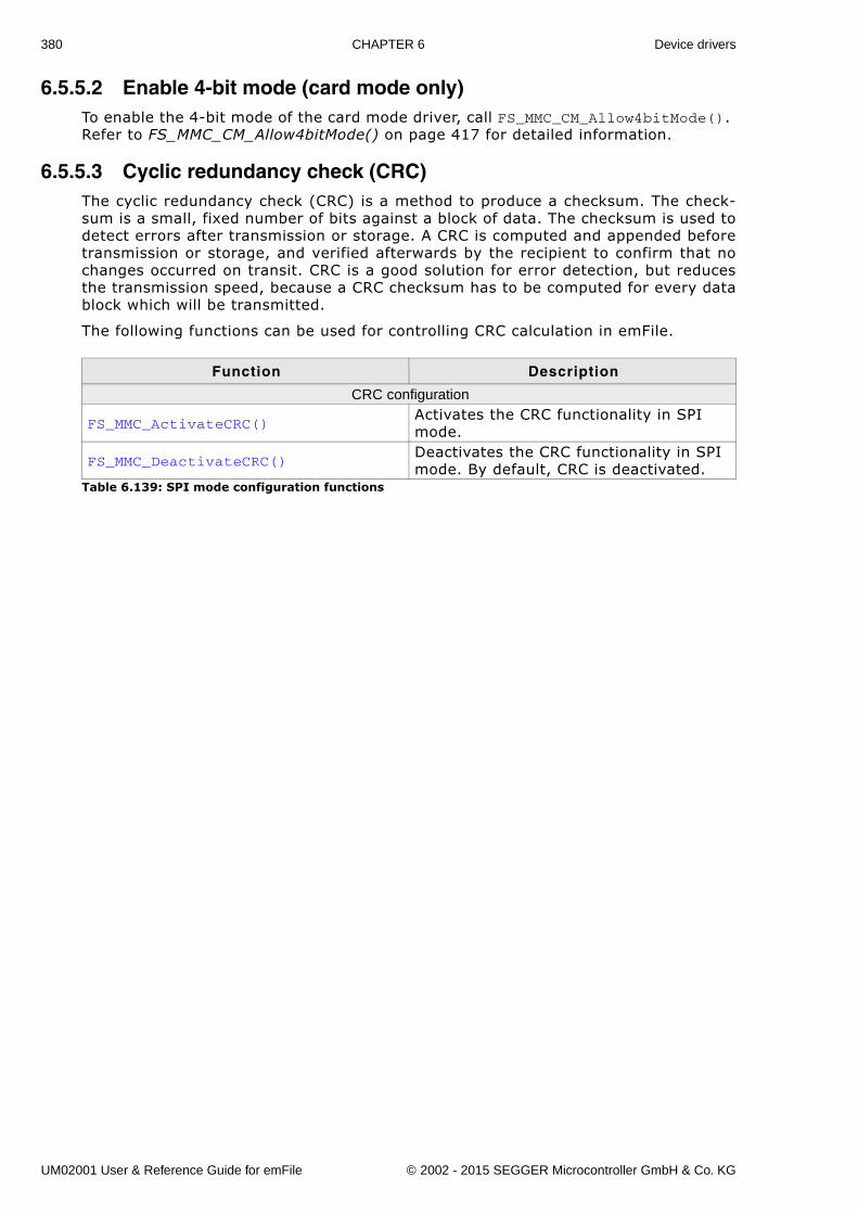
380 CHAPTER 6 Device drivers
6.5.5.2 Enable 4-bit mode (card mode only)To enable the 4-bit mode of the card mode driver, call FS_MMC_CM_Allow4bitMode(). Refer to FS_MMC_CM_Allow4bitMode() on page 417 for detailed information.
6.5.5.3 Cyclic redundancy check (CRC)The cyclic redundancy check (CRC) is a method to produce a checksum. The check-sum is a small, fixed number of bits against a block of data. The checksum is used todetect errors after transmission or storage. A CRC is computed and appended beforetransmission or storage, and verified afterwards by the recipient to confirm that nochanges occurred on transit. CRC is a good solution for error detection, but reducesthe transmission speed, because a CRC checksum has to be computed for every datablock which will be transmitted.
The following functions can be used for controlling CRC calculation in emFile.
Function Description
CRC configuration
FS_MMC_ActivateCRC()Activates the CRC functionality in SPI mode.
FS_MMC_DeactivateCRC()Deactivates the CRC functionality in SPI mode. By default, CRC is deactivated.
Table 6.139: SPI mode configuration functions
UM02001 User & Reference Guide for emFile © 2002 - 2015 SEGGER Microcontroller GmbH & Co. KG
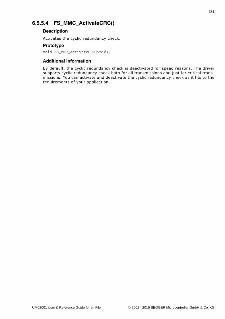
381
6.5.5.4 FS_MMC_ActivateCRC()Description
Activates the cyclic redundancy check.
Prototypevoid FS_MMC_ActivateCRC(void);
Additional information
By default, the cyclic redundancy check is deactivated for speed reasons. The driversupports cyclic redundancy check both for all transmissions and just for critical trans-missions. You can activate and deactivate the cyclic redundancy check as it fits to therequirements of your application.
UM02001 User & Reference Guide for emFile © 2002 - 2015 SEGGER Microcontroller GmbH & Co. KG
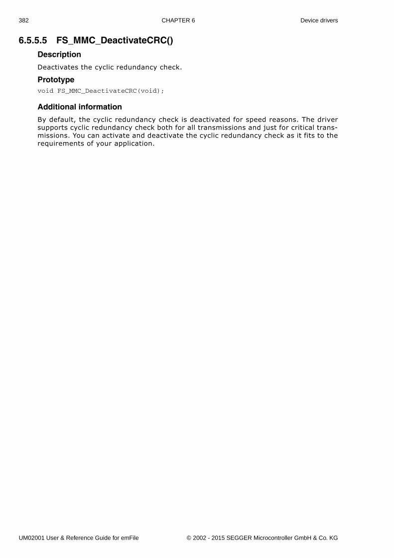
382 CHAPTER 6 Device drivers
6.5.5.5 FS_MMC_DeactivateCRC()Description
Deactivates the cyclic redundancy check.
Prototypevoid FS_MMC_DeactivateCRC(void);
Additional information
By default, the cyclic redundancy check is deactivated for speed reasons. The driversupports cyclic redundancy check both for all transmissions and just for critical trans-missions. You can activate and deactivate the cyclic redundancy check as it fits to therequirements of your application.
UM02001 User & Reference Guide for emFile © 2002 - 2015 SEGGER Microcontroller GmbH & Co. KG
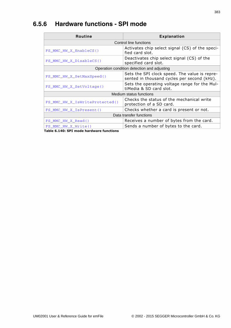
383
6.5.6 Hardware functions - SPI mode
Routine Explanation
Control line functions
FS_MMC_HW_X_EnableCS()Activates chip select signal (CS) of the speci-fied card slot.
FS_MMC_HW_X_DisableCS()Deactivates chip select signal (CS) of the specified card slot.
Operation condition detection and adjusting
FS_MMC_HW_X_SetMaxSpeed()Sets the SPI clock speed. The value is repre-sented in thousand cycles per second (kHz).
FS_MMC_HW_X_SetVoltage()Sets the operating voltage range for the Mul-tiMedia & SD card slot.
Medium status functions
FS_MMC_HW_X_IsWriteProtected()Checks the status of the mechanical write protection of a SD card.
FS_MMC_HW_X_IsPresent() Checks whether a card is present or not.Data transfer functions
FS_MMC_HW_X_Read() Receives a number of bytes from the card.FS_MMC_HW_X_Write() Sends a number of bytes to the card.
Table 6.140: SPI mode hardware functions
UM02001 User & Reference Guide for emFile © 2002 - 2015 SEGGER Microcontroller GmbH & Co. KG
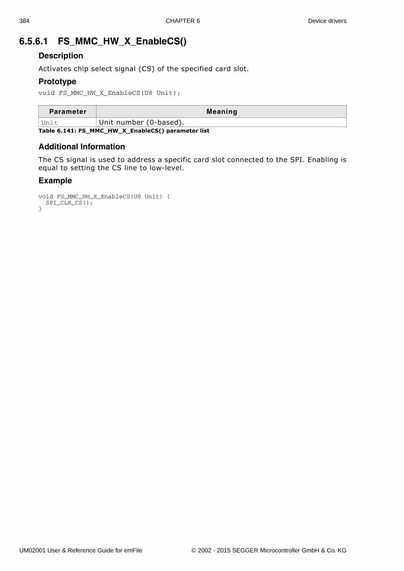
384 CHAPTER 6 Device drivers
6.5.6.1 FS_MMC_HW_X_EnableCS()Description
Activates chip select signal (CS) of the specified card slot.
Prototypevoid FS_MMC_HW_X_EnableCS(U8 Unit);
Additional Information
The CS signal is used to address a specific card slot connected to the SPI. Enabling isequal to setting the CS line to low-level.
Example
void FS_MMC_HW_X_EnableCS(U8 Unit) { SPI_CLR_CS();}
Parameter Meaning
Unit Unit number (0-based).Table 6.141: FS_MMC_HW_X_EnableCS() parameter list
UM02001 User & Reference Guide for emFile © 2002 - 2015 SEGGER Microcontroller GmbH & Co. KG
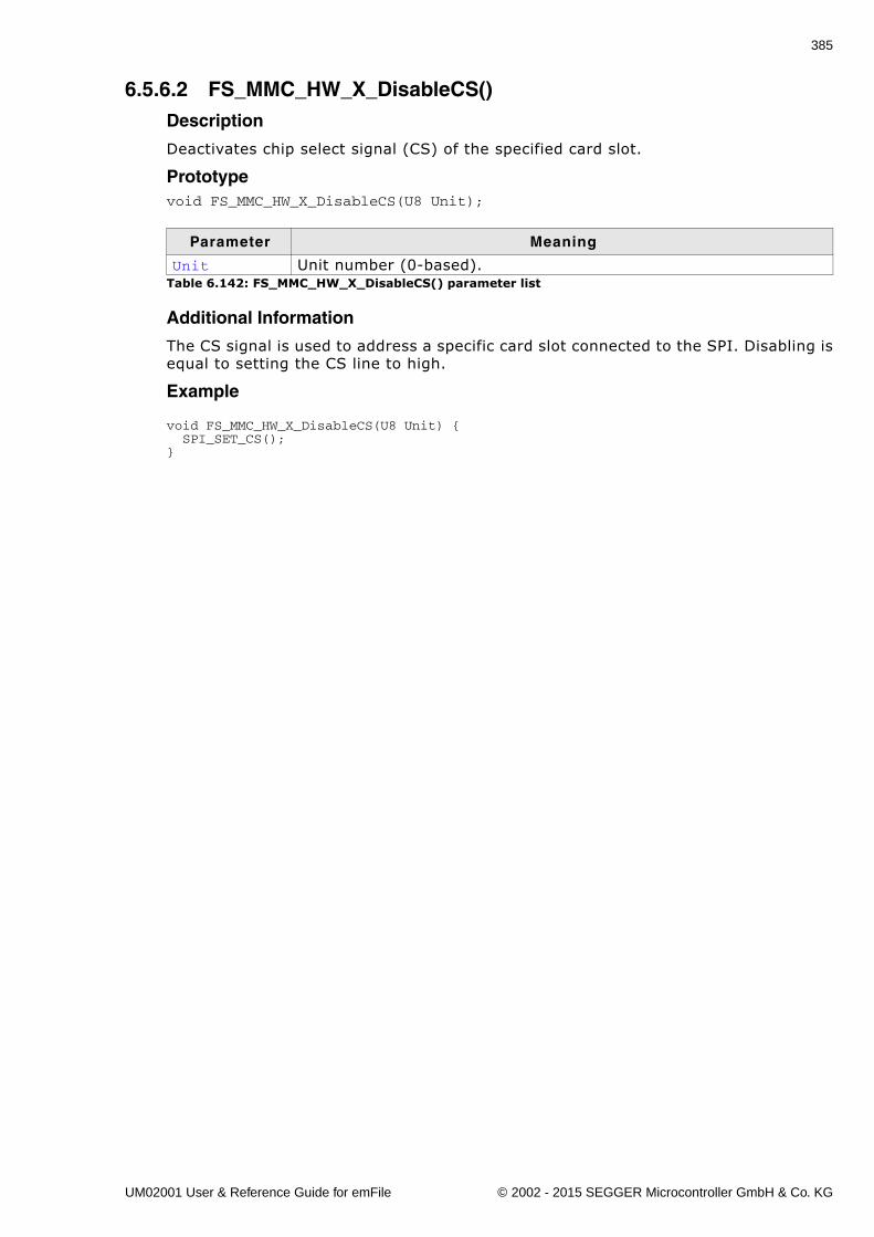
385
6.5.6.2 FS_MMC_HW_X_DisableCS()Description
Deactivates chip select signal (CS) of the specified card slot.
Prototypevoid FS_MMC_HW_X_DisableCS(U8 Unit);
Additional Information
The CS signal is used to address a specific card slot connected to the SPI. Disabling isequal to setting the CS line to high.
Example
void FS_MMC_HW_X_DisableCS(U8 Unit) { SPI_SET_CS();}
Parameter Meaning
Unit Unit number (0-based).Table 6.142: FS_MMC_HW_X_DisableCS() parameter list
UM02001 User & Reference Guide for emFile © 2002 - 2015 SEGGER Microcontroller GmbH & Co. KG
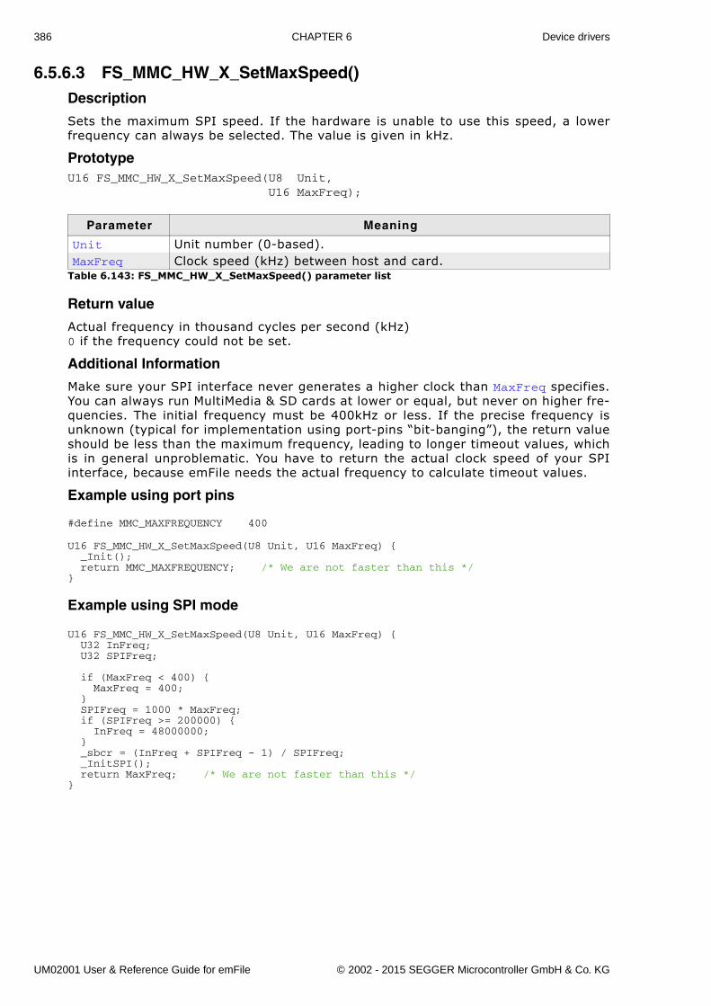
386 CHAPTER 6 Device drivers
6.5.6.3 FS_MMC_HW_X_SetMaxSpeed()Description
Sets the maximum SPI speed. If the hardware is unable to use this speed, a lowerfrequency can always be selected. The value is given in kHz.
PrototypeU16 FS_MMC_HW_X_SetMaxSpeed(U8 Unit, U16 MaxFreq);
Return value
Actual frequency in thousand cycles per second (kHz)0 if the frequency could not be set.
Additional Information
Make sure your SPI interface never generates a higher clock than MaxFreq specifies.You can always run MultiMedia & SD cards at lower or equal, but never on higher fre-quencies. The initial frequency must be 400kHz or less. If the precise frequency isunknown (typical for implementation using port-pins �bit-banging�), the return valueshould be less than the maximum frequency, leading to longer timeout values, whichis in general unproblematic. You have to return the actual clock speed of your SPIinterface, because emFile needs the actual frequency to calculate timeout values.
Example using port pins
#define MMC_MAXFREQUENCY 400
U16 FS_MMC_HW_X_SetMaxSpeed(U8 Unit, U16 MaxFreq) { _Init(); return MMC_MAXFREQUENCY; /* We are not faster than this */}
Example using SPI mode
U16 FS_MMC_HW_X_SetMaxSpeed(U8 Unit, U16 MaxFreq) { U32 InFreq; U32 SPIFreq;
if (MaxFreq < 400) { MaxFreq = 400; } SPIFreq = 1000 * MaxFreq; if (SPIFreq >= 200000) { InFreq = 48000000; } _sbcr = (InFreq + SPIFreq - 1) / SPIFreq; _InitSPI(); return MaxFreq; /* We are not faster than this */}
Parameter Meaning
Unit Unit number (0-based).MaxFreq Clock speed (kHz) between host and card.
Table 6.143: FS_MMC_HW_X_SetMaxSpeed() parameter list
UM02001 User & Reference Guide for emFile © 2002 - 2015 SEGGER Microcontroller GmbH & Co. KG
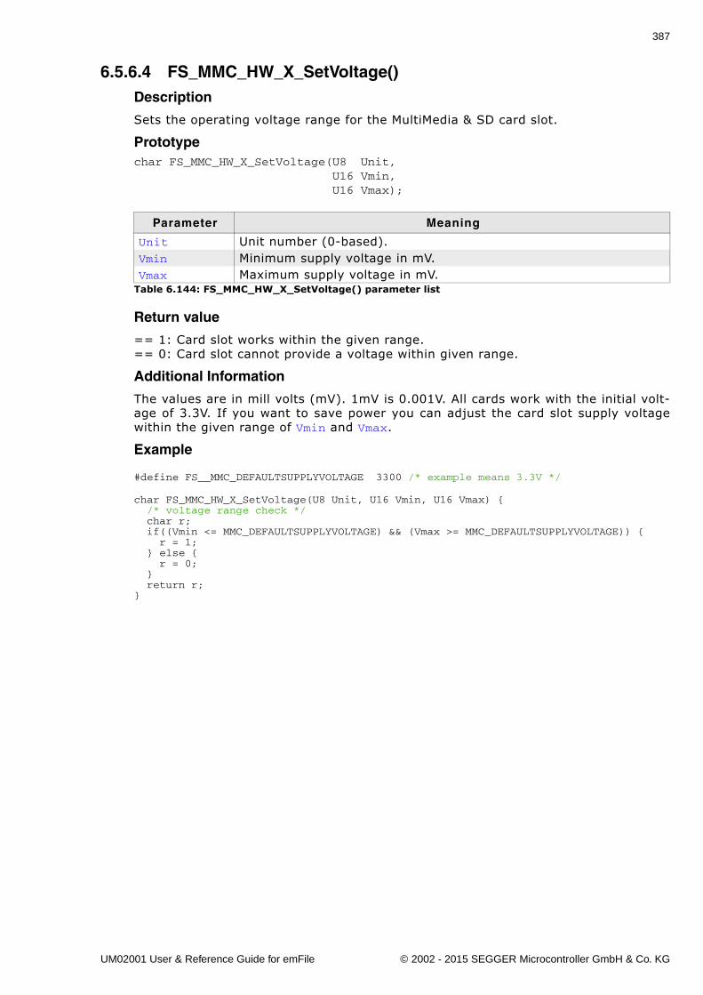
387
6.5.6.4 FS_MMC_HW_X_SetVoltage()Description
Sets the operating voltage range for the MultiMedia & SD card slot.
Prototypechar FS_MMC_HW_X_SetVoltage(U8 Unit, U16 Vmin, U16 Vmax);
Return value
== 1: Card slot works within the given range.== 0: Card slot cannot provide a voltage within given range.
Additional Information
The values are in mill volts (mV). 1mV is 0.001V. All cards work with the initial volt-age of 3.3V. If you want to save power you can adjust the card slot supply voltagewithin the given range of Vmin and Vmax.
Example
#define FS__MMC_DEFAULTSUPPLYVOLTAGE 3300 /* example means 3.3V */
char FS_MMC_HW_X_SetVoltage(U8 Unit, U16 Vmin, U16 Vmax) { /* voltage range check */ char r; if((Vmin <= MMC_DEFAULTSUPPLYVOLTAGE) && (Vmax >= MMC_DEFAULTSUPPLYVOLTAGE)) { r = 1; } else { r = 0; } return r; }
Parameter Meaning
Unit Unit number (0-based).Vmin Minimum supply voltage in mV.Vmax Maximum supply voltage in mV.
Table 6.144: FS_MMC_HW_X_SetVoltage() parameter list
UM02001 User & Reference Guide for emFile © 2002 - 2015 SEGGER Microcontroller GmbH & Co. KG
388 CHAPTER 6 Device drivers
6.5.6.5 FS_MMC_HW_X_IsWriteProtected()Description
Checks the status of the mechanical write protection of a SD card.
Prototypechar FS_MMC_HW_X_IsWriteProtected(U8 Unit);
Return value
== 0: If the card is not write protected.== 1: Means that the card is write protected.
Additional Information
MultiMedia cards do not have mechanical write protection switches and should alwaysreturn 0. If you are using SD cards, be aware that the mechanical switch does notreally protect the card physically from being overwritten; it is the responsibility ofthe host to respect the status of that switch.
Example
char FS_MMC_HW_X_IsWriteProtected(U8 Unit) { return 0; /* If the card slot has no write switch detector, return 0 */}
Parameter Meaning
Unit Unit number (0-based).Table 6.145: FS_MMC_HW_X_IsWriteProtected() parameter list
UM02001 User & Reference Guide for emFile © 2002 - 2015 SEGGER Microcontroller GmbH & Co. KG
389
6.5.6.6 FS_MMC_HW_X_IsPresent()Description
Checks whether a card is present or not.
Prototypechar FS_MMC_HW_X_IsPresent(U8 Unit);
Return value
Additional Information
Usually, a card slot provides a hardware signal that can be used for card presencedetermination. The sample code below is for a specific hardware that does not havesuch a signal. Therefore, the presence of a card is unknown and you have to returnFS_MEDIA_STATE_UNKNOWN. Then emFile tries reading the card to figure out if a validcard is inserted into the slot.
Example
char FS_MMC_HW_X_IsPresent(U8 Unit) { return FS_MEDIA_STATE_UNKNOWN; }
Parameter Meaning
Unit Unit number (0-based).Table 6.146: FS_MMC_HW_X_IsPresent() parameter list
Return value Description
FS_MEDIA_STATE_UNKNOWN The card state is unknown.FS_MEDIA_NOT_PRESENT A card is not present.FS_MEDIA_IS_PRESENT A card is present.
Table 6.147: FS_MMC_HW_X_IsPresent() - list of return values
UM02001 User & Reference Guide for emFile © 2002 - 2015 SEGGER Microcontroller GmbH & Co. KG
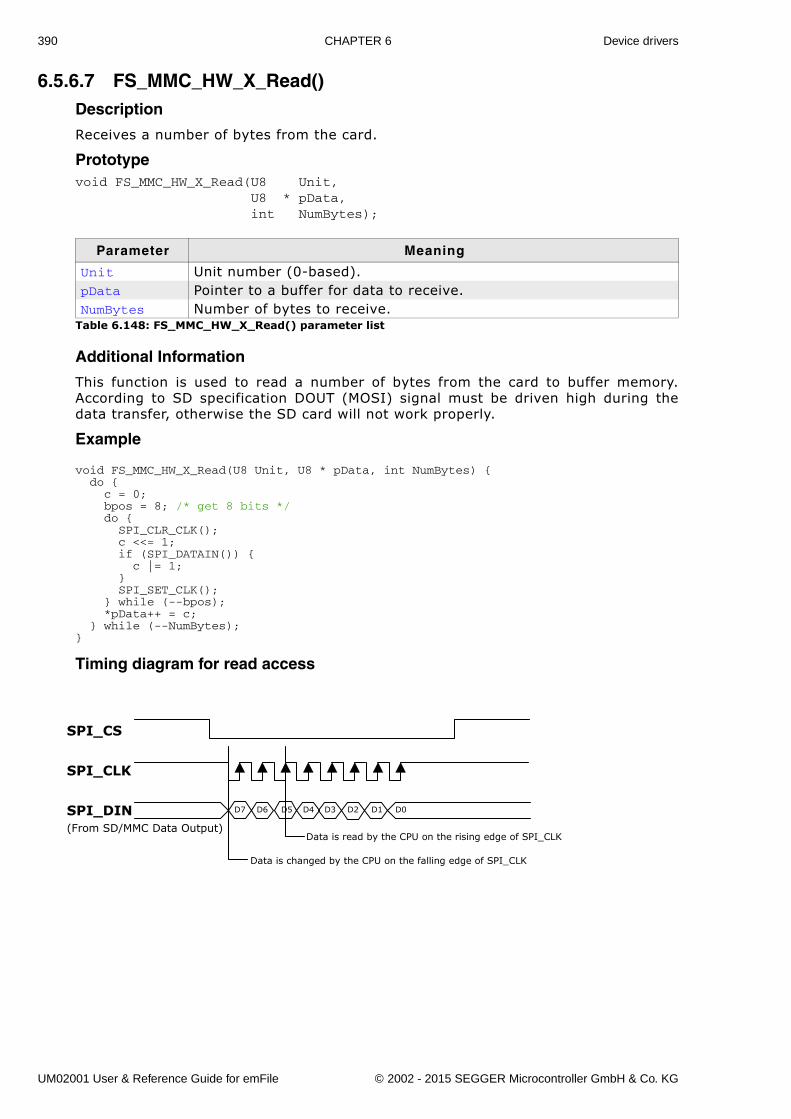
390 CHAPTER 6 Device drivers
6.5.6.7 FS_MMC_HW_X_Read()Description
Receives a number of bytes from the card.
Prototypevoid FS_MMC_HW_X_Read(U8 Unit, U8 * pData, int NumBytes);
Additional Information
This function is used to read a number of bytes from the card to buffer memory.According to SD specification DOUT (MOSI) signal must be driven high during thedata transfer, otherwise the SD card will not work properly.
Example
void FS_MMC_HW_X_Read(U8 Unit, U8 * pData, int NumBytes) { do { c = 0; bpos = 8; /* get 8 bits */ do { SPI_CLR_CLK(); c <<= 1; if (SPI_DATAIN()) { c |= 1; } SPI_SET_CLK(); } while (--bpos); *pData++ = c; } while (--NumBytes); }
Timing diagram for read access
Parameter Meaning
Unit Unit number (0-based).pData Pointer to a buffer for data to receive.NumBytes Number of bytes to receive.
Table 6.148: FS_MMC_HW_X_Read() parameter list
SPI_DIN
Data is changed by the CPU on the falling edge of SPI_CLK
Data is read by the CPU on the rising edge of SPI_CLK
D7
(From SD/MMC Data Output)
D6 D5 D4 D3 D2 D1 D0
SPI_CLK
SPI_CS
UM02001 User & Reference Guide for emFile © 2002 - 2015 SEGGER Microcontroller GmbH & Co. KG
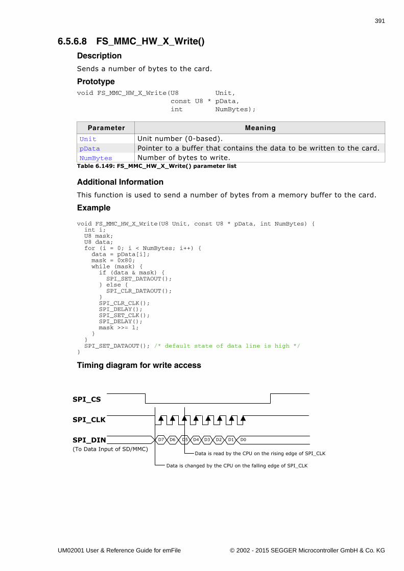
391
6.5.6.8 FS_MMC_HW_X_Write()Description
Sends a number of bytes to the card.
Prototypevoid FS_MMC_HW_X_Write(U8 Unit, const U8 * pData, int NumBytes);
Additional Information
This function is used to send a number of bytes from a memory buffer to the card.
Example
void FS_MMC_HW_X_Write(U8 Unit, const U8 * pData, int NumBytes) { int i; U8 mask; U8 data; for (i = 0; i < NumBytes; i++) { data = pData[i]; mask = 0x80; while (mask) { if (data & mask) { SPI_SET_DATAOUT(); } else { SPI_CLR_DATAOUT(); } SPI_CLR_CLK(); SPI_DELAY(); SPI_SET_CLK(); SPI_DELAY(); mask >>= 1; } } SPI_SET_DATAOUT(); /* default state of data line is high */ }
Timing diagram for write access
Parameter Meaning
Unit Unit number (0-based).pData Pointer to a buffer that contains the data to be written to the card.NumBytes Number of bytes to write.
Table 6.149: FS_MMC_HW_X_Write() parameter list
SPI_DIN
Data is changed by the CPU on the falling edge of SPI_CLK
Data is read by the CPU on the rising edge of SPI_CLK
D7
(To Data Input of SD/MMC)
D6 D5 D4 D3 D2 D1 D0
SPI_CLK
SPI_CS
UM02001 User & Reference Guide for emFile © 2002 - 2015 SEGGER Microcontroller GmbH & Co. KG
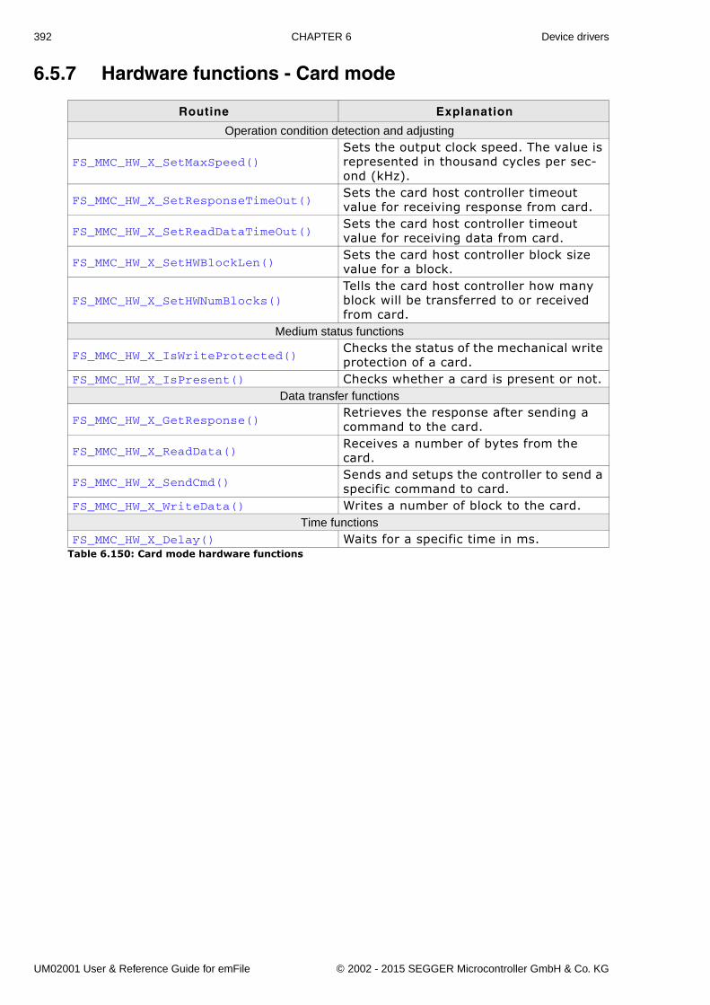
392 CHAPTER 6 Device drivers
6.5.7 Hardware functions - Card mode
Routine Explanation
Operation condition detection and adjusting
FS_MMC_HW_X_SetMaxSpeed()Sets the output clock speed. The value is represented in thousand cycles per sec-ond (kHz).
FS_MMC_HW_X_SetResponseTimeOut()Sets the card host controller timeout value for receiving response from card.
FS_MMC_HW_X_SetReadDataTimeOut()Sets the card host controller timeout value for receiving data from card.
FS_MMC_HW_X_SetHWBlockLen()Sets the card host controller block size value for a block.
FS_MMC_HW_X_SetHWNumBlocks()Tells the card host controller how many block will be transferred to or received from card.
Medium status functions
FS_MMC_HW_X_IsWriteProtected()Checks the status of the mechanical write protection of a card.
FS_MMC_HW_X_IsPresent() Checks whether a card is present or not.Data transfer functions
FS_MMC_HW_X_GetResponse()Retrieves the response after sending a command to the card.
FS_MMC_HW_X_ReadData()Receives a number of bytes from the card.
FS_MMC_HW_X_SendCmd()Sends and setups the controller to send a specific command to card.
FS_MMC_HW_X_WriteData() Writes a number of block to the card.Time functions
FS_MMC_HW_X_Delay() Waits for a specific time in ms.Table 6.150: Card mode hardware functions
UM02001 User & Reference Guide for emFile © 2002 - 2015 SEGGER Microcontroller GmbH & Co. KG
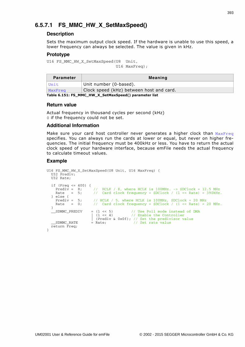
393
6.5.7.1 FS_MMC_HW_X_SetMaxSpeed()Description
Sets the maximum output clock speed. If the hardware is unable to use this speed, alower frequency can always be selected. The value is given in kHz.
PrototypeU16 FS_MMC_HW_X_SetMaxSpeed(U8 Unit, U16 MaxFreq);
Return value
Actual frequency in thousand cycles per second (kHz)0 if the frequency could not be set.
Additional Information
Make sure your card host controller never generates a higher clock than MaxFreqspecifies. You can always run the cards at lower or equal, but never on higher fre-quencies. The initial frequency must be 400kHz or less. You have to return the actualclock speed of your hardware interface, because emFile needs the actual frequencyto calculate timeout values.
Example
U16 FS_MMC_HW_X_SetMaxSpeed(U8 Unit, U16 MaxFreq) { U32 Prediv; U32 Rate;
if (Freq <= 400) { Prediv = 8; // HCLK / 8, where HCLK is 100MHz. -> SDClock = 12.5 MHz Rate = 5; // Card clock frequency = SDClock / (1 << Rate) = 390kHz. } else { Prediv = 5; // HCLK / 5, where HCLK is 100MHz, SDClock = 20 MHz Rate = 0; // Card clock frequency = SDClock / (1 << Rate) = 20 MHz. } __SDMMC_PREDIV = (1 << 5) // Use Poll mode instead of DMA | (1 << 4) // Enable the Controller | (Prediv & 0x0f); // Set the predivisor value __SDMMC_RATE = Rate; // Set rate value return Freq;}
Parameter Meaning
Unit Unit number (0-based).MaxFreq Clock speed (kHz) between host and card.
Table 6.151: FS_MMC_HW_X_SetMaxSpeed() parameter list
UM02001 User & Reference Guide for emFile © 2002 - 2015 SEGGER Microcontroller GmbH & Co. KG
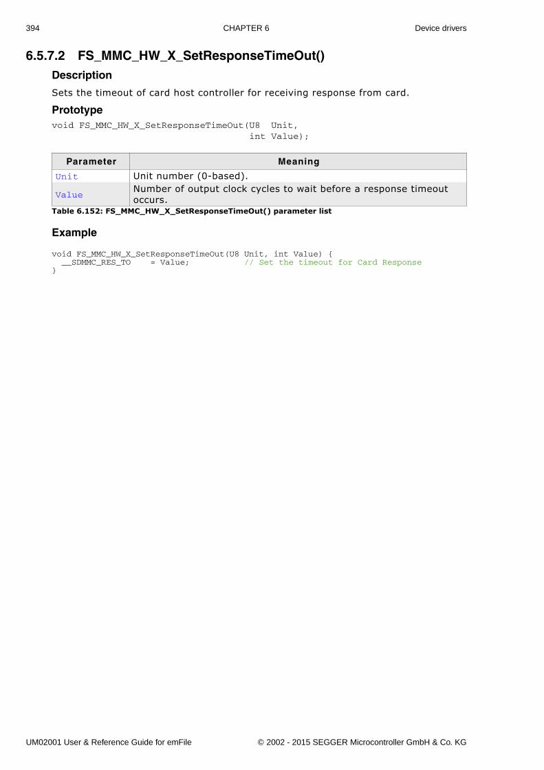
394 CHAPTER 6 Device drivers
6.5.7.2 FS_MMC_HW_X_SetResponseTimeOut()Description
Sets the timeout of card host controller for receiving response from card.
Prototypevoid FS_MMC_HW_X_SetResponseTimeOut(U8 Unit, int Value);
Example
void FS_MMC_HW_X_SetResponseTimeOut(U8 Unit, int Value) { __SDMMC_RES_TO = Value; // Set the timeout for Card Response}
Parameter Meaning
Unit Unit number (0-based).
ValueNumber of output clock cycles to wait before a response timeout occurs.
Table 6.152: FS_MMC_HW_X_SetResponseTimeOut() parameter list
UM02001 User & Reference Guide for emFile © 2002 - 2015 SEGGER Microcontroller GmbH & Co. KG
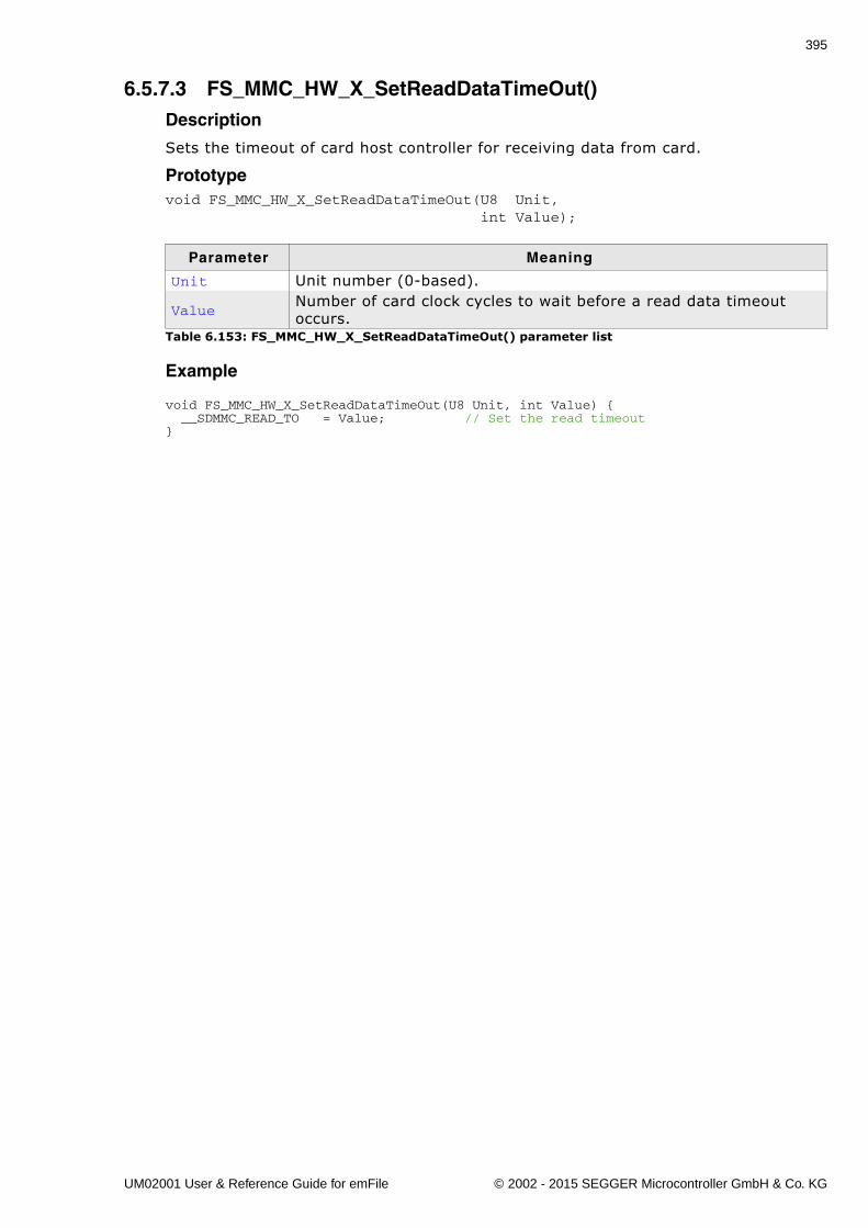
395
6.5.7.3 FS_MMC_HW_X_SetReadDataTimeOut()Description
Sets the timeout of card host controller for receiving data from card.
Prototypevoid FS_MMC_HW_X_SetReadDataTimeOut(U8 Unit, int Value);
Example
void FS_MMC_HW_X_SetReadDataTimeOut(U8 Unit, int Value) { __SDMMC_READ_TO = Value; // Set the read timeout}
Parameter Meaning
Unit Unit number (0-based).
ValueNumber of card clock cycles to wait before a read data timeout occurs.
Table 6.153: FS_MMC_HW_X_SetReadDataTimeOut() parameter list
UM02001 User & Reference Guide for emFile © 2002 - 2015 SEGGER Microcontroller GmbH & Co. KG
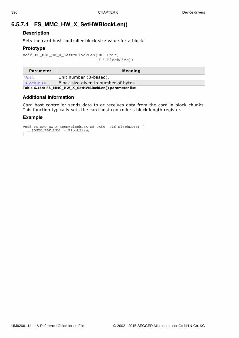
396 CHAPTER 6 Device drivers
6.5.7.4 FS_MMC_HW_X_SetHWBlockLen()Description
Sets the card host controller block size value for a block.
Prototypevoid FS_MMC_HW_X_SetHWBlockLen(U8 Unit, U16 BlockSize);
Additional Information
Card host controller sends data to or receives data from the card in block chunks.This function typically sets the card host controller's block length register.
Example
void FS_MMC_HW_X_SetHWBlockLen(U8 Unit, U16 BlockSize) { __SDMMC_BLK_LEN = BlockSize;}
Parameter Meaning
Unit Unit number (0-based).BlockSize Block size given in number of bytes.
Table 6.154: FS_MMC_HW_X_SetHWBlockLen() parameter list
UM02001 User & Reference Guide for emFile © 2002 - 2015 SEGGER Microcontroller GmbH & Co. KG
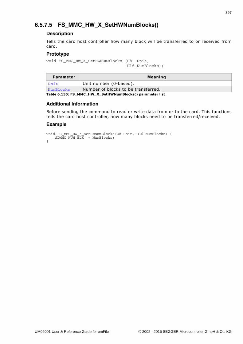
397
6.5.7.5 FS_MMC_HW_X_SetHWNumBlocks()Description
Tells the card host controller how many block will be transferred to or received fromcard.
Prototypevoid FS_MMC_HW_X_SetHWNumBlocks (U8 Unit, U16 NumBlocks);
Additional Information
Before sending the command to read or write data from or to the card. This functionstells the card host controller, how many blocks need to be transferred/received.
Example
void FS_MMC_HW_X_SetHWNumBlocks(U8 Unit, U16 NumBlocks) { __SDMMC_NUM_BLK = NumBlocks;}
Parameter Meaning
Unit Unit number (0-based).NumBlocks Number of blocks to be transferred.
Table 6.155: FS_MMC_HW_X_SetHWNumBlocks() parameter list
UM02001 User & Reference Guide for emFile © 2002 - 2015 SEGGER Microcontroller GmbH & Co. KG
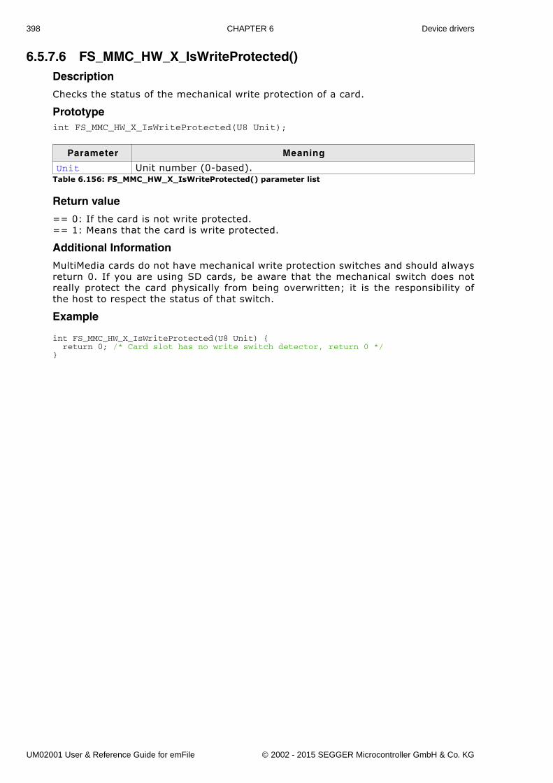
398 CHAPTER 6 Device drivers
6.5.7.6 FS_MMC_HW_X_IsWriteProtected()Description
Checks the status of the mechanical write protection of a card.
Prototypeint FS_MMC_HW_X_IsWriteProtected(U8 Unit);
Return value
== 0: If the card is not write protected.== 1: Means that the card is write protected.
Additional Information
MultiMedia cards do not have mechanical write protection switches and should alwaysreturn 0. If you are using SD cards, be aware that the mechanical switch does notreally protect the card physically from being overwritten; it is the responsibility ofthe host to respect the status of that switch.
Example
int FS_MMC_HW_X_IsWriteProtected(U8 Unit) { return 0; /* Card slot has no write switch detector, return 0 */}
Parameter Meaning
Unit Unit number (0-based).Table 6.156: FS_MMC_HW_X_IsWriteProtected() parameter list
UM02001 User & Reference Guide for emFile © 2002 - 2015 SEGGER Microcontroller GmbH & Co. KG
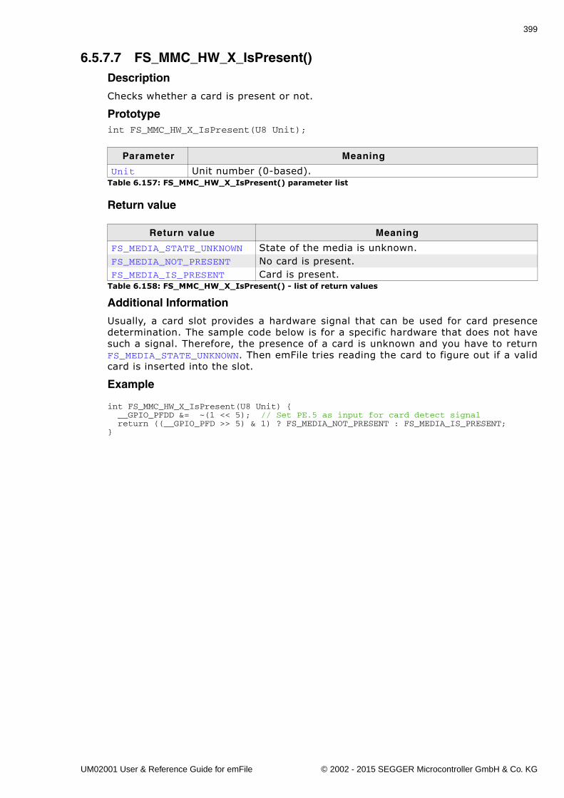
399
6.5.7.7 FS_MMC_HW_X_IsPresent()Description
Checks whether a card is present or not.
Prototypeint FS_MMC_HW_X_IsPresent(U8 Unit);
Return value
Additional Information
Usually, a card slot provides a hardware signal that can be used for card presencedetermination. The sample code below is for a specific hardware that does not havesuch a signal. Therefore, the presence of a card is unknown and you have to returnFS_MEDIA_STATE_UNKNOWN. Then emFile tries reading the card to figure out if a validcard is inserted into the slot.
Example
int FS_MMC_HW_X_IsPresent(U8 Unit) { __GPIO_PFDD &= ~(1 << 5); // Set PE.5 as input for card detect signal return ((__GPIO_PFD >> 5) & 1) ? FS_MEDIA_NOT_PRESENT : FS_MEDIA_IS_PRESENT;}
Parameter Meaning
Unit Unit number (0-based).Table 6.157: FS_MMC_HW_X_IsPresent() parameter list
Return value Meaning
FS_MEDIA_STATE_UNKNOWN State of the media is unknown.FS_MEDIA_NOT_PRESENT No card is present.FS_MEDIA_IS_PRESENT Card is present.
Table 6.158: FS_MMC_HW_X_IsPresent() - list of return values
UM02001 User & Reference Guide for emFile © 2002 - 2015 SEGGER Microcontroller GmbH & Co. KG
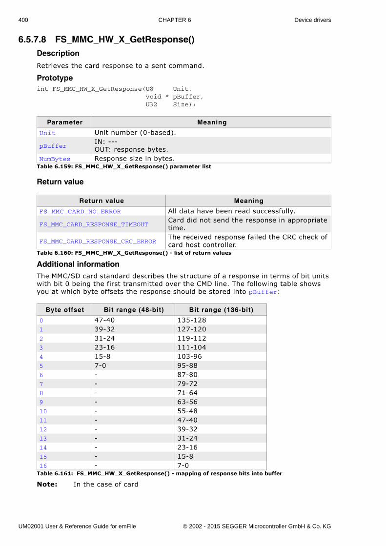
400 CHAPTER 6 Device drivers
6.5.7.8 FS_MMC_HW_X_GetResponse()Description
Retrieves the card response to a sent command.
Prototypeint FS_MMC_HW_X_GetResponse(U8 Unit, void * pBuffer, U32 Size);
Return value
Additional informationThe MMC/SD card standard describes the structure of a response in terms of bit units with bit 0 being the first transmitted over the CMD line. The following table shows you at which byte offsets the response should be stored into pBuffer:
Note: In the case of card
Parameter Meaning
Unit Unit number (0-based).
pBufferIN: ---OUT: response bytes.
NumBytes Response size in bytes.Table 6.159: FS_MMC_HW_X_GetResponse() parameter list
Return value Meaning
FS_MMC_CARD_NO_ERROR All data have been read successfully.
FS_MMC_CARD_RESPONSE_TIMEOUTCard did not send the response in appropriate time.
FS_MMC_CARD_RESPONSE_CRC_ERRORThe received response failed the CRC check of card host controller.
Table 6.160: FS_MMC_HW_X_GetResponse() - list of return values
Byte offset Bit range (48-bit) Bit range (136-bit)
0 47-40 135-1281 39-32 127-1202 31-24 119-1123 23-16 111-1044 15-8 103-965 7-0 95-886 - 87-807 - 79-728 - 71-649 - 63-5610 - 55-4811 - 47-4012 - 39-3213 - 31-2414 - 23-1615 - 15-816 - 7-0
Table 6.161: FS_MMC_HW_X_GetResponse() - mapping of response bits into buffer
UM02001 User & Reference Guide for emFile © 2002 - 2015 SEGGER Microcontroller GmbH & Co. KG
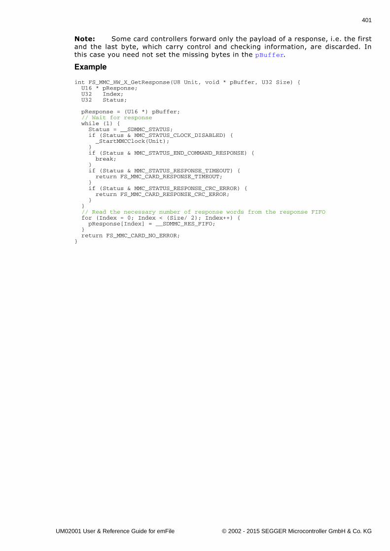
401
Note: Some card controllers forward only the payload of a response, i.e. the firstand the last byte, which carry control and checking information, are discarded. Inthis case you need not set the missing bytes in the pBuffer.
Example
int FS_MMC_HW_X_GetResponse(U8 Unit, void * pBuffer, U32 Size) { U16 * pResponse; U32 Index; U32 Status;
pResponse = (U16 *) pBuffer; // Wait for response while (1) { Status = __SDMMC_STATUS; if (Status & MMC_STATUS_CLOCK_DISABLED) { _StartMMCClock(Unit); } if (Status & MMC_STATUS_END_COMMAND_RESPONSE) { break; } if (Status & MMC_STATUS_RESPONSE_TIMEOUT) { return FS_MMC_CARD_RESPONSE_TIMEOUT; } if (Status & MMC_STATUS_RESPONSE_CRC_ERROR) { return FS_MMC_CARD_RESPONSE_CRC_ERROR; } } // Read the necessary number of response words from the response FIFO for (Index = 0; Index < (Size/ 2); Index++) { pResponse[Index] = __SDMMC_RES_FIFO; } return FS_MMC_CARD_NO_ERROR;}
UM02001 User & Reference Guide for emFile © 2002 - 2015 SEGGER Microcontroller GmbH & Co. KG
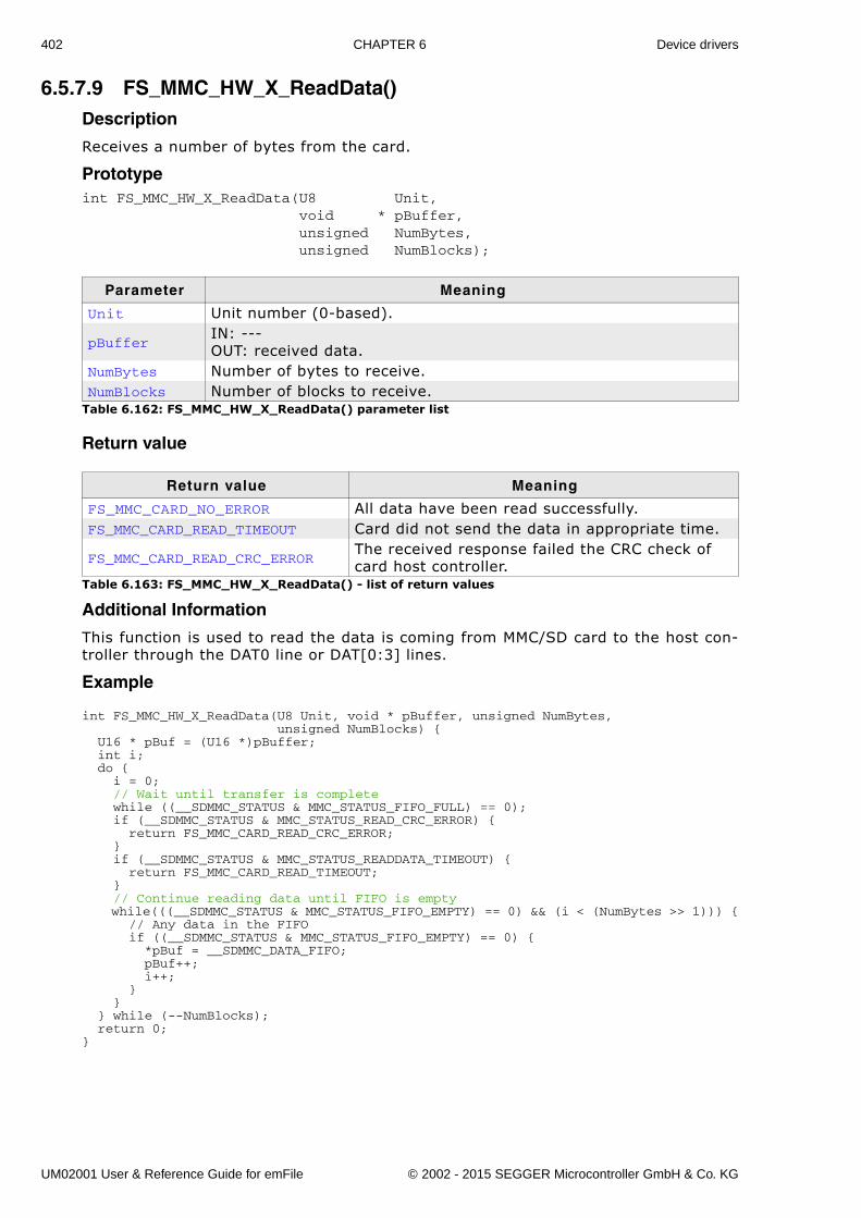
402 CHAPTER 6 Device drivers
6.5.7.9 FS_MMC_HW_X_ReadData()Description
Receives a number of bytes from the card.
Prototypeint FS_MMC_HW_X_ReadData(U8 Unit, void * pBuffer, unsigned NumBytes, unsigned NumBlocks);
Return value
Additional Information
This function is used to read the data is coming from MMC/SD card to the host con-troller through the DAT0 line or DAT[0:3] lines.
Example
int FS_MMC_HW_X_ReadData(U8 Unit, void * pBuffer, unsigned NumBytes, unsigned NumBlocks) { U16 * pBuf = (U16 *)pBuffer; int i; do { i = 0; // Wait until transfer is complete while ((__SDMMC_STATUS & MMC_STATUS_FIFO_FULL) == 0); if (__SDMMC_STATUS & MMC_STATUS_READ_CRC_ERROR) { return FS_MMC_CARD_READ_CRC_ERROR; } if (__SDMMC_STATUS & MMC_STATUS_READDATA_TIMEOUT) { return FS_MMC_CARD_READ_TIMEOUT; } // Continue reading data until FIFO is empty while(((__SDMMC_STATUS & MMC_STATUS_FIFO_EMPTY) == 0) && (i < (NumBytes >> 1))) { // Any data in the FIFO if ((__SDMMC_STATUS & MMC_STATUS_FIFO_EMPTY) == 0) { *pBuf = __SDMMC_DATA_FIFO; pBuf++; i++; } } } while (--NumBlocks); return 0;}
Parameter Meaning
Unit Unit number (0-based).
pBufferIN: ---OUT: received data.
NumBytes Number of bytes to receive.NumBlocks Number of blocks to receive.
Table 6.162: FS_MMC_HW_X_ReadData() parameter list
Return value Meaning
FS_MMC_CARD_NO_ERROR All data have been read successfully.FS_MMC_CARD_READ_TIMEOUT Card did not send the data in appropriate time.
FS_MMC_CARD_READ_CRC_ERRORThe received response failed the CRC check of card host controller.
Table 6.163: FS_MMC_HW_X_ReadData() - list of return values
UM02001 User & Reference Guide for emFile © 2002 - 2015 SEGGER Microcontroller GmbH & Co. KG
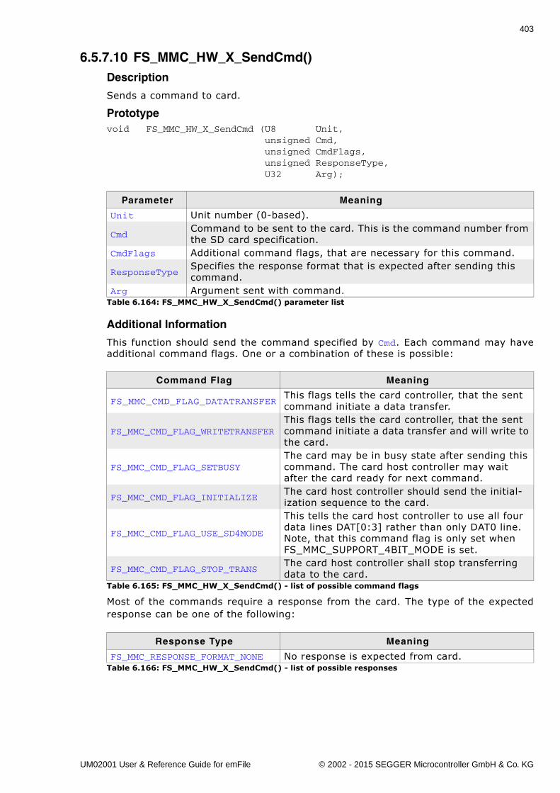
403
6.5.7.10 FS_MMC_HW_X_SendCmd()Description
Sends a command to card.
Prototypevoid FS_MMC_HW_X_SendCmd (U8 Unit, unsigned Cmd, unsigned CmdFlags, unsigned ResponseType, U32 Arg);
Additional Information
This function should send the command specified by Cmd. Each command may haveadditional command flags. One or a combination of these is possible:
Most of the commands require a response from the card. The type of the expectedresponse can be one of the following:
Parameter Meaning
Unit Unit number (0-based).
CmdCommand to be sent to the card. This is the command number from the SD card specification.
CmdFlags Additional command flags, that are necessary for this command.
ResponseTypeSpecifies the response format that is expected after sending this command.
Arg Argument sent with command.Table 6.164: FS_MMC_HW_X_SendCmd() parameter list
Command Flag Meaning
FS_MMC_CMD_FLAG_DATATRANSFERThis flags tells the card controller, that the sent command initiate a data transfer.
FS_MMC_CMD_FLAG_WRITETRANSFERThis flags tells the card controller, that the sent command initiate a data transfer and will write to the card.
FS_MMC_CMD_FLAG_SETBUSYThe card may be in busy state after sending this command. The card host controller may wait after the card ready for next command.
FS_MMC_CMD_FLAG_INITIALIZEThe card host controller should send the initial-ization sequence to the card.
FS_MMC_CMD_FLAG_USE_SD4MODE
This tells the card host controller to use all four data lines DAT[0:3] rather than only DAT0 line. Note, that this command flag is only set when FS_MMC_SUPPORT_4BIT_MODE is set.
FS_MMC_CMD_FLAG_STOP_TRANSThe card host controller shall stop transferring data to the card.
Table 6.165: FS_MMC_HW_X_SendCmd() - list of possible command flags
Response Type Meaning
FS_MMC_RESPONSE_FORMAT_NONE No response is expected from card.Table 6.166: FS_MMC_HW_X_SendCmd() - list of possible responses
UM02001 User & Reference Guide for emFile © 2002 - 2015 SEGGER Microcontroller GmbH & Co. KG
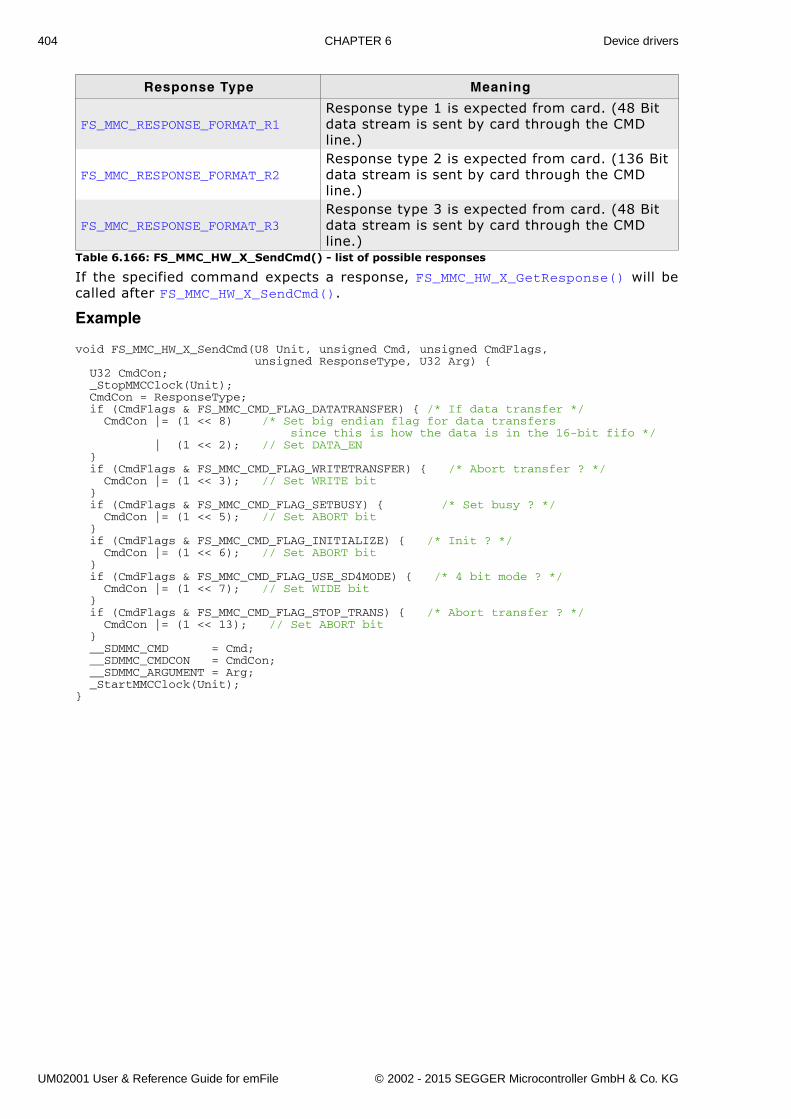
404 CHAPTER 6 Device drivers
If the specified command expects a response, FS_MMC_HW_X_GetResponse() will becalled after FS_MMC_HW_X_SendCmd().
Example
void FS_MMC_HW_X_SendCmd(U8 Unit, unsigned Cmd, unsigned CmdFlags, unsigned ResponseType, U32 Arg) { U32 CmdCon; _StopMMCClock(Unit); CmdCon = ResponseType; if (CmdFlags & FS_MMC_CMD_FLAG_DATATRANSFER) { /* If data transfer */ CmdCon |= (1 << 8) /* Set big endian flag for data transfers since this is how the data is in the 16-bit fifo */ | (1 << 2); // Set DATA_EN } if (CmdFlags & FS_MMC_CMD_FLAG_WRITETRANSFER) { /* Abort transfer ? */ CmdCon |= (1 << 3); // Set WRITE bit } if (CmdFlags & FS_MMC_CMD_FLAG_SETBUSY) { /* Set busy ? */ CmdCon |= (1 << 5); // Set ABORT bit } if (CmdFlags & FS_MMC_CMD_FLAG_INITIALIZE) { /* Init ? */ CmdCon |= (1 << 6); // Set ABORT bit } if (CmdFlags & FS_MMC_CMD_FLAG_USE_SD4MODE) { /* 4 bit mode ? */ CmdCon |= (1 << 7); // Set WIDE bit } if (CmdFlags & FS_MMC_CMD_FLAG_STOP_TRANS) { /* Abort transfer ? */ CmdCon |= (1 << 13); // Set ABORT bit } __SDMMC_CMD = Cmd; __SDMMC_CMDCON = CmdCon; __SDMMC_ARGUMENT = Arg; _StartMMCClock(Unit);}
FS_MMC_RESPONSE_FORMAT_R1Response type 1 is expected from card. (48 Bit data stream is sent by card through the CMD line.)
FS_MMC_RESPONSE_FORMAT_R2Response type 2 is expected from card. (136 Bit data stream is sent by card through the CMD line.)
FS_MMC_RESPONSE_FORMAT_R3Response type 3 is expected from card. (48 Bit data stream is sent by card through the CMD line.)
Response Type Meaning
Table 6.166: FS_MMC_HW_X_SendCmd() - list of possible responses
UM02001 User & Reference Guide for emFile © 2002 - 2015 SEGGER Microcontroller GmbH & Co. KG
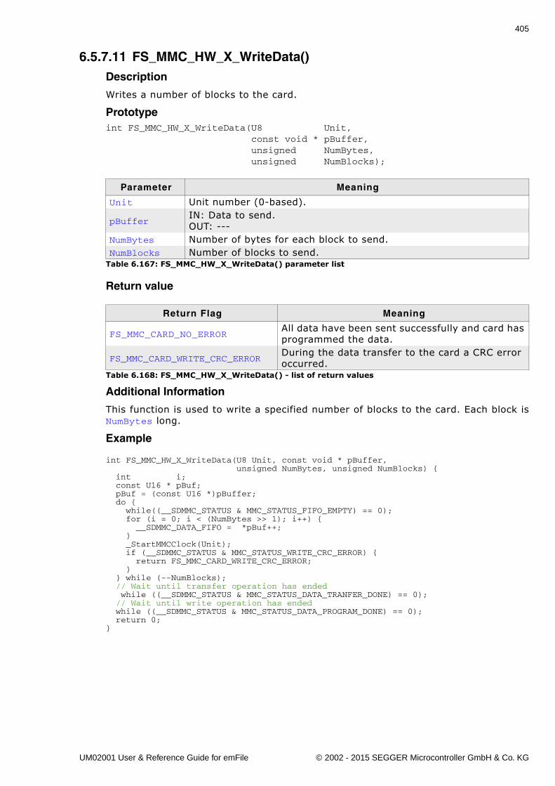
405
6.5.7.11 FS_MMC_HW_X_WriteData()Description
Writes a number of blocks to the card.
Prototypeint FS_MMC_HW_X_WriteData(U8 Unit, const void * pBuffer, unsigned NumBytes, unsigned NumBlocks);
Return value
Additional Information
This function is used to write a specified number of blocks to the card. Each block isNumBytes long.
Example
int FS_MMC_HW_X_WriteData(U8 Unit, const void * pBuffer, unsigned NumBytes, unsigned NumBlocks) { int i; const U16 * pBuf; pBuf = (const U16 *)pBuffer; do { while((__SDMMC_STATUS & MMC_STATUS_FIFO_EMPTY) == 0); for (i = 0; i < (NumBytes >> 1); i++) { __SDMMC_DATA_FIFO = *pBuf++; } _StartMMCClock(Unit); if (__SDMMC_STATUS & MMC_STATUS_WRITE_CRC_ERROR) { return FS_MMC_CARD_WRITE_CRC_ERROR; } } while (--NumBlocks); // Wait until transfer operation has ended while ((__SDMMC_STATUS & MMC_STATUS_DATA_TRANFER_DONE) == 0); // Wait until write operation has ended while ((__SDMMC_STATUS & MMC_STATUS_DATA_PROGRAM_DONE) == 0); return 0;}
Parameter Meaning
Unit Unit number (0-based).
pBufferIN: Data to send.OUT: ---
NumBytes Number of bytes for each block to send.NumBlocks Number of blocks to send.
Table 6.167: FS_MMC_HW_X_WriteData() parameter list
Return Flag Meaning
FS_MMC_CARD_NO_ERRORAll data have been sent successfully and card has programmed the data.
FS_MMC_CARD_WRITE_CRC_ERRORDuring the data transfer to the card a CRC error occurred.
Table 6.168: FS_MMC_HW_X_WriteData() - list of return values
UM02001 User & Reference Guide for emFile © 2002 - 2015 SEGGER Microcontroller GmbH & Co. KG
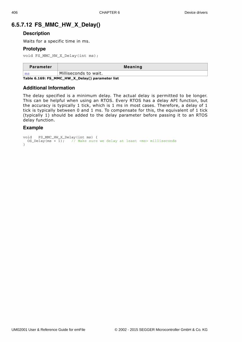
406 CHAPTER 6 Device drivers
6.5.7.12 FS_MMC_HW_X_Delay()Description
Waits for a specific time in ms.
Prototypevoid FS_MMC_HW_X_Delay(int ms);
Additional Information
The delay specified is a minimum delay. The actual delay is permitted to be longer.This can be helpful when using an RTOS. Every RTOS has a delay API function, butthe accuracy is typically 1 tick, which is 1 ms in most cases. Therefore, a delay of 1tick is typically between 0 and 1 ms. To compensate for this, the equivalent of 1 tick(typically 1) should be added to the delay parameter before passing it to an RTOSdelay function.
Example
void FS_MMC_HW_X_Delay(int ms) { OS_Delay(ms + 1); // Make sure we delay at least <ms> milliseconds}
Parameter Meaning
ms Milliseconds to wait.Table 6.169: FS_MMC_HW_X_Delay() parameter list
UM02001 User & Reference Guide for emFile © 2002 - 2015 SEGGER Microcontroller GmbH & Co. KG
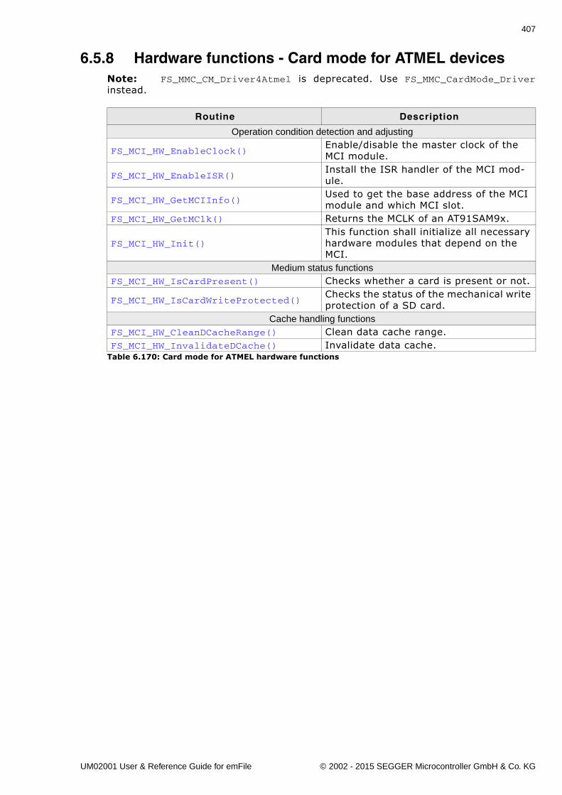
407
6.5.8 Hardware functions - Card mode for ATMEL devicesNote: FS_MMC_CM_Driver4Atmel is deprecated. Use FS_MMC_CardMode_Driverinstead.
Routine Description
Operation condition detection and adjusting
FS_MCI_HW_EnableClock()Enable/disable the master clock of the MCI module.
FS_MCI_HW_EnableISR()Install the ISR handler of the MCI mod-ule.
FS_MCI_HW_GetMCIInfo()Used to get the base address of the MCI module and which MCI slot.
FS_MCI_HW_GetMClk() Returns the MCLK of an AT91SAM9x.
FS_MCI_HW_Init()This function shall initialize all necessary hardware modules that depend on the MCI.
Medium status functionsFS_MCI_HW_IsCardPresent() Checks whether a card is present or not.
FS_MCI_HW_IsCardWriteProtected()Checks the status of the mechanical write protection of a SD card.
Cache handling functionsFS_MCI_HW_CleanDCacheRange() Clean data cache range.FS_MCI_HW_InvalidateDCache() Invalidate data cache.
Table 6.170: Card mode for ATMEL hardware functions
UM02001 User & Reference Guide for emFile © 2002 - 2015 SEGGER Microcontroller GmbH & Co. KG
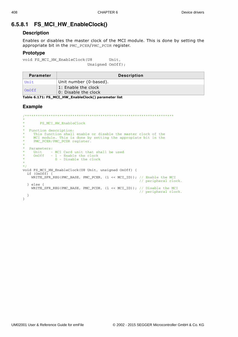
408 CHAPTER 6 Device drivers
6.5.8.1 FS_MCI_HW_EnableClock()Description
Enables or disables the master clock of the MCI module. This is done by setting theappropriate bit in the PMC_PCER/PMC_PCDR register.
Prototypevoid FS_MCI_HW_EnableClock(U8 Unit, Unsigned OnOff);
Example
/*********************************************************************** FS_MCI_HW_EnableClock** Function description:* This function shall enable or disable the master clock of the * MCI module. This is done by setting the appropiate bit in the* PMC_PCER/PMC_PCDR register.** Parameters:* Unit - MCI Card unit that shall be used* OnOff - 1 - Enable the clock* 0 - Disable the clock**/void FS_MCI_HW_EnableClock(U8 Unit, unsigned OnOff) { if (OnOff) { WRITE_SFR_REG(PMC_BASE, PMC_PCER, (1 << MCI_ID)); // Enable the MCI // peripheral clock. } else { WRITE_SFR_REG(PMC_BASE, PMC_PCDR, (1 << MCI_ID)); // Disable the MCI // peripheral clock. }}
Parameter Description
Unit Unit number (0-based).
OnOff1: Enable the clock0: Disable the clock
Table 6.171: FS_MCI_HW_EnableClock() parameter list
UM02001 User & Reference Guide for emFile © 2002 - 2015 SEGGER Microcontroller GmbH & Co. KG
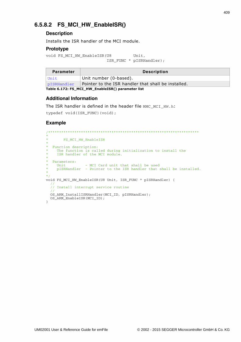
409
6.5.8.2 FS_MCI_HW_EnableISR()Description
Installs the ISR handler of the MCI module.
Prototypevoid FS_MCI_HW_EnableISR(U8 Unit, ISR_FUNC * pISRHandler);
Additional Information
The ISR handler is defined in the header file MMC_MCI_HW.h:
typedef void(ISR_FUNC)(void);
Example
/*********************************************************************** FS_MCI_HW_EnableISR** Function description:* The function is called during initialization to install the* ISR handler of the MCI module.** Parameters:* Unit - MCI Card unit that shall be used* pISRHandler - Pointer to the ISR handler that shall be installed.* */void FS_MCI_HW_EnableISR(U8 Unit, ISR_FUNC * pISRHandler) { // // Install interrupt service routine // OS_ARM_InstallISRHandler(MCI_ID, pISRHandler); OS_ARM_EnableISR(MCI_ID);}
Parameter Description
Unit Unit number (0-based).pISRHandler Pointer to the ISR handler that shall be installed.
Table 6.172: FS_MCI_HW_EnableISR() parameter list
UM02001 User & Reference Guide for emFile © 2002 - 2015 SEGGER Microcontroller GmbH & Co. KG
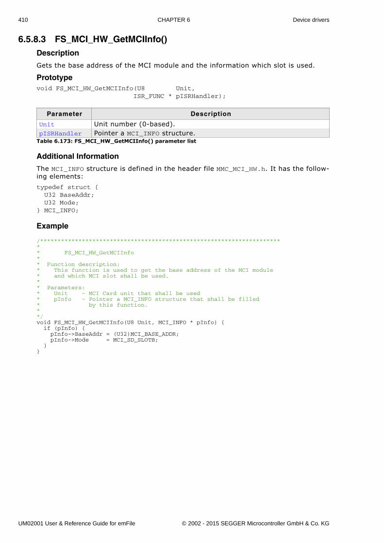
410 CHAPTER 6 Device drivers
6.5.8.3 FS_MCI_HW_GetMCIInfo()Description
Gets the base address of the MCI module and the information which slot is used.
Prototypevoid FS_MCI_HW_GetMCIInfo(U8 Unit, ISR_FUNC * pISRHandler);
Additional Information
The MCI_INFO structure is defined in the header file MMC_MCI_HW.h. It has the follow-ing elements:
typedef struct { U32 BaseAddr; U32 Mode;} MCI_INFO;
Example
/*********************************************************************** FS_MCI_HW_GetMCIInfo** Function description:* This function is used to get the base address of the MCI module * and which MCI slot shall be used.** Parameters:* Unit - MCI Card unit that shall be used* pInfo - Pointer a MCI_INFO structure that shall be filled* by this function.* */void FS_MCI_HW_GetMCIInfo(U8 Unit, MCI_INFO * pInfo) { if (pInfo) { pInfo->BaseAddr = (U32)MCI_BASE_ADDR; pInfo->Mode = MCI_SD_SLOTB; }}
Parameter Description
Unit Unit number (0-based).pISRHandler Pointer a MCI_INFO structure.
Table 6.173: FS_MCI_HW_GetMCIInfo() parameter list
UM02001 User & Reference Guide for emFile © 2002 - 2015 SEGGER Microcontroller GmbH & Co. KG
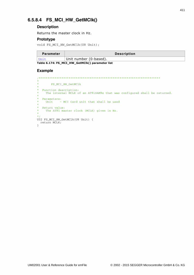
411
6.5.8.4 FS_MCI_HW_GetMClk()Description
Returns the master clock in Hz.
Prototypevoid FS_MCI_HW_GetMClk(U8 Unit);
Example
/*********************************************************************** FS_MCI_HW_GetMClk** Function description:* The internal MCLK of an AT91SAM9x that was configured shall be returned.** Parameters:* Unit - MCI Card unit that shall be used* * Return value:* The AT91 master clock (MCLK) given in Hz.**/U32 FS_MCI_HW_GetMClk(U8 Unit) { return MCLK;}
Parameter Description
Unit Unit number (0-based).Table 6.174: FS_MCI_HW_GetMClk() parameter list
UM02001 User & Reference Guide for emFile © 2002 - 2015 SEGGER Microcontroller GmbH & Co. KG
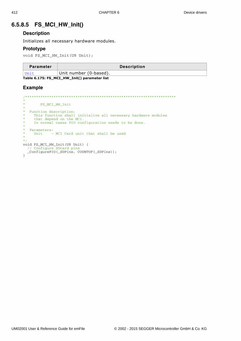
412 CHAPTER 6 Device drivers
6.5.8.5 FS_MCI_HW_Init()Description
Initializes all necessary hardware modules.
Prototypevoid FS_MCI_HW_Init(U8 Unit);
Example
/*********************************************************************** FS_MCI_HW_Init** Function description:* This function shall initialize all necessary hardware modules* that depend on the MCI.* In normal cases PIO configuration needs to be done.** Parameters:* Unit - MCI Card unit that shall be used* */void FS_MCI_HW_Init(U8 Unit) { // Configure SDcard pins _ConfigurePIO(_SDPins, COUNTOF(_SDPins));}
Parameter Description
Unit Unit number (0-based).Table 6.175: FS_MCI_HW_Init() parameter list
UM02001 User & Reference Guide for emFile © 2002 - 2015 SEGGER Microcontroller GmbH & Co. KG
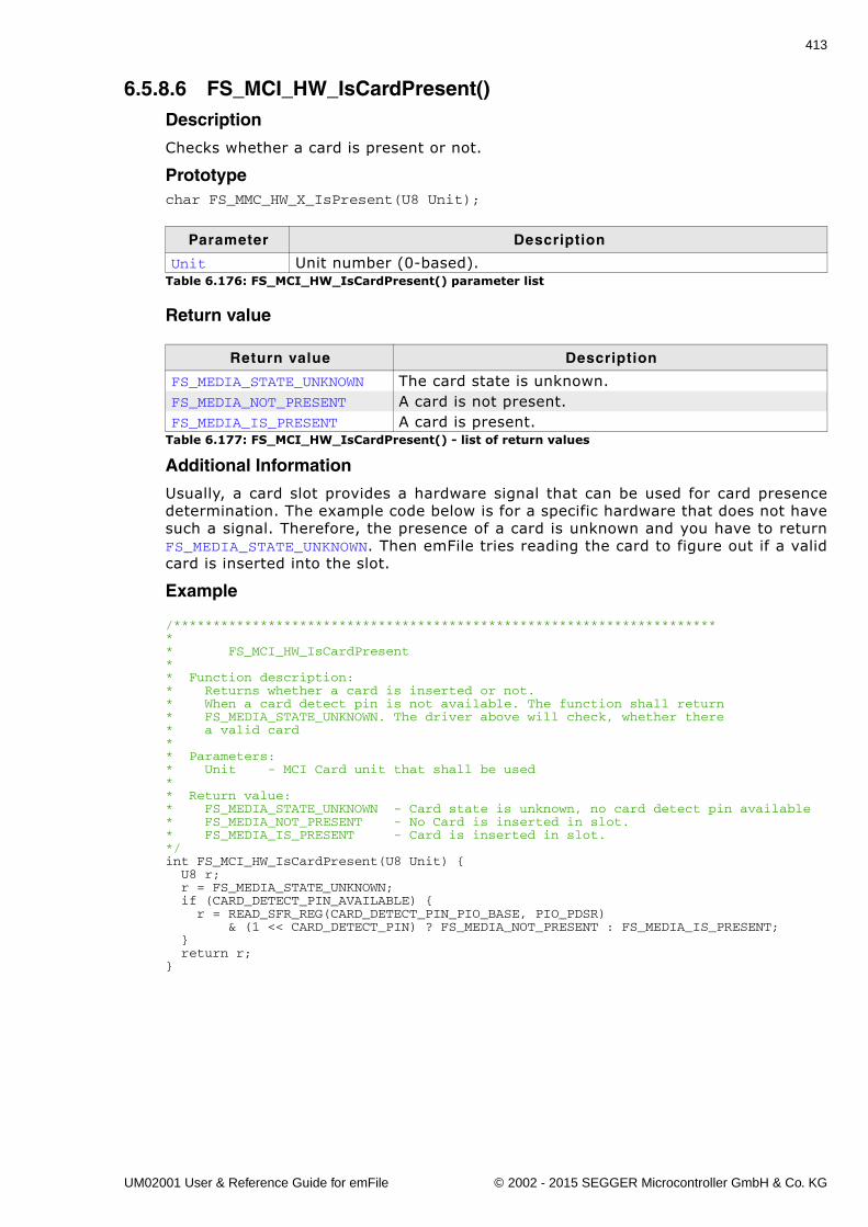
413
6.5.8.6 FS_MCI_HW_IsCardPresent()Description
Checks whether a card is present or not.
Prototypechar FS_MMC_HW_X_IsPresent(U8 Unit);
Return value
Additional Information
Usually, a card slot provides a hardware signal that can be used for card presencedetermination. The example code below is for a specific hardware that does not havesuch a signal. Therefore, the presence of a card is unknown and you have to returnFS_MEDIA_STATE_UNKNOWN. Then emFile tries reading the card to figure out if a validcard is inserted into the slot.
Example
/*********************************************************************** FS_MCI_HW_IsCardPresent** Function description:* Returns whether a card is inserted or not.* When a card detect pin is not available. The function shall return* FS_MEDIA_STATE_UNKNOWN. The driver above will check, whether there* a valid card** Parameters:* Unit - MCI Card unit that shall be used* * Return value:* FS_MEDIA_STATE_UNKNOWN - Card state is unknown, no card detect pin available* FS_MEDIA_NOT_PRESENT - No Card is inserted in slot.* FS_MEDIA_IS_PRESENT - Card is inserted in slot.*/int FS_MCI_HW_IsCardPresent(U8 Unit) { U8 r; r = FS_MEDIA_STATE_UNKNOWN; if (CARD_DETECT_PIN_AVAILABLE) { r = READ_SFR_REG(CARD_DETECT_PIN_PIO_BASE, PIO_PDSR) & (1 << CARD_DETECT_PIN) ? FS_MEDIA_NOT_PRESENT : FS_MEDIA_IS_PRESENT; } return r;}
Parameter Description
Unit Unit number (0-based).Table 6.176: FS_MCI_HW_IsCardPresent() parameter list
Return value Description
FS_MEDIA_STATE_UNKNOWN The card state is unknown.FS_MEDIA_NOT_PRESENT A card is not present.FS_MEDIA_IS_PRESENT A card is present.
Table 6.177: FS_MCI_HW_IsCardPresent() - list of return values
UM02001 User & Reference Guide for emFile © 2002 - 2015 SEGGER Microcontroller GmbH & Co. KG
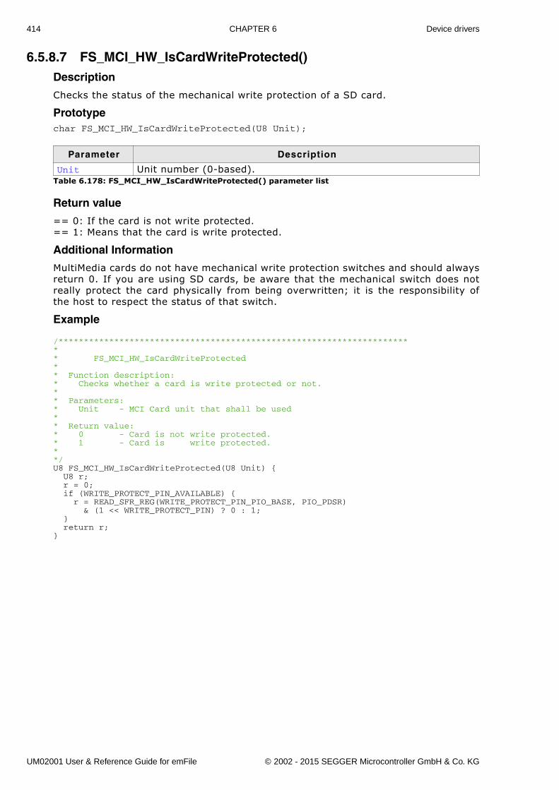
414 CHAPTER 6 Device drivers
6.5.8.7 FS_MCI_HW_IsCardWriteProtected()Description
Checks the status of the mechanical write protection of a SD card.
Prototypechar FS_MCI_HW_IsCardWriteProtected(U8 Unit);
Return value
== 0: If the card is not write protected.== 1: Means that the card is write protected.
Additional Information
MultiMedia cards do not have mechanical write protection switches and should alwaysreturn 0. If you are using SD cards, be aware that the mechanical switch does notreally protect the card physically from being overwritten; it is the responsibility ofthe host to respect the status of that switch.
Example
/*********************************************************************** FS_MCI_HW_IsCardWriteProtected** Function description:* Checks whether a card is write protected or not.** Parameters:* Unit - MCI Card unit that shall be used* * Return value:* 0 - Card is not write protected.* 1 - Card is write protected.**/U8 FS_MCI_HW_IsCardWriteProtected(U8 Unit) { U8 r; r = 0; if (WRITE_PROTECT_PIN_AVAILABLE) { r = READ_SFR_REG(WRITE_PROTECT_PIN_PIO_BASE, PIO_PDSR) & (1 << WRITE_PROTECT_PIN) ? 0 : 1; } return r;}
Parameter Description
Unit Unit number (0-based).Table 6.178: FS_MCI_HW_IsCardWriteProtected() parameter list
UM02001 User & Reference Guide for emFile © 2002 - 2015 SEGGER Microcontroller GmbH & Co. KG
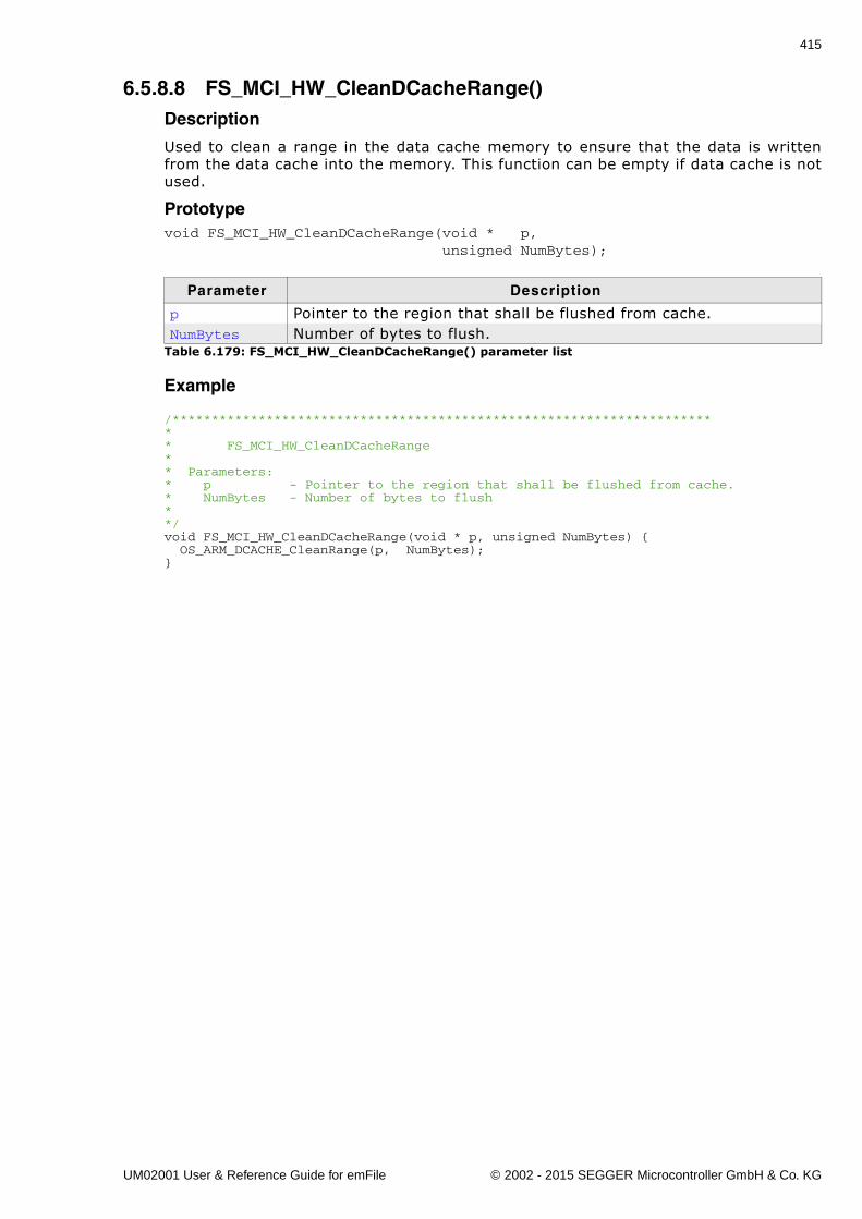
415
6.5.8.8 FS_MCI_HW_CleanDCacheRange()Description
Used to clean a range in the data cache memory to ensure that the data is writtenfrom the data cache into the memory. This function can be empty if data cache is notused.
Prototypevoid FS_MCI_HW_CleanDCacheRange(void * p, unsigned NumBytes);
Example
/*********************************************************************** FS_MCI_HW_CleanDCacheRange** Parameters:* p - Pointer to the region that shall be flushed from cache.* NumBytes - Number of bytes to flush* */void FS_MCI_HW_CleanDCacheRange(void * p, unsigned NumBytes) { OS_ARM_DCACHE_CleanRange(p, NumBytes);}
Parameter Description
p Pointer to the region that shall be flushed from cache.NumBytes Number of bytes to flush.
Table 6.179: FS_MCI_HW_CleanDCacheRange() parameter list
UM02001 User & Reference Guide for emFile © 2002 - 2015 SEGGER Microcontroller GmbH & Co. KG
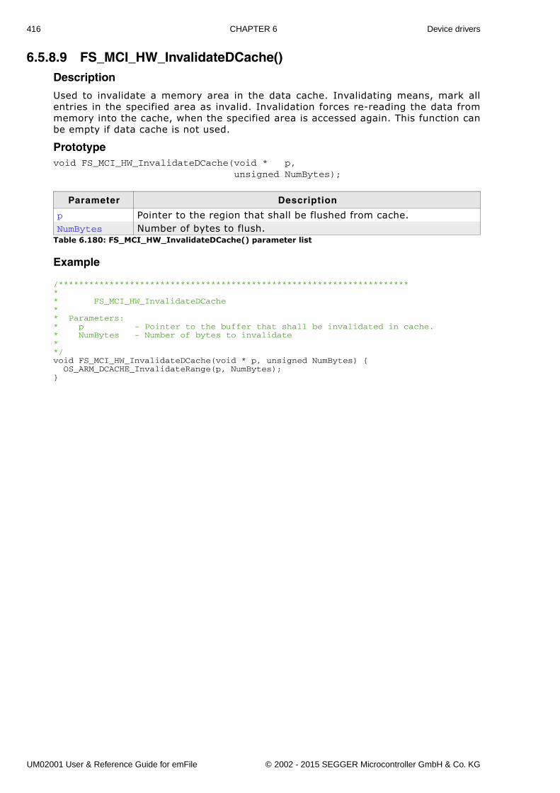
416 CHAPTER 6 Device drivers
6.5.8.9 FS_MCI_HW_InvalidateDCache()Description
Used to invalidate a memory area in the data cache. Invalidating means, mark allentries in the specified area as invalid. Invalidation forces re-reading the data frommemory into the cache, when the specified area is accessed again. This function canbe empty if data cache is not used.
Prototypevoid FS_MCI_HW_InvalidateDCache(void * p, unsigned NumBytes);
Example
/*********************************************************************** FS_MCI_HW_InvalidateDCache** Parameters:* p - Pointer to the buffer that shall be invalidated in cache.* NumBytes - Number of bytes to invalidate* */void FS_MCI_HW_InvalidateDCache(void * p, unsigned NumBytes) { OS_ARM_DCACHE_InvalidateRange(p, NumBytes);}
Parameter Description
p Pointer to the region that shall be flushed from cache.NumBytes Number of bytes to flush.
Table 6.180: FS_MCI_HW_InvalidateDCache() parameter list
UM02001 User & Reference Guide for emFile © 2002 - 2015 SEGGER Microcontroller GmbH & Co. KG
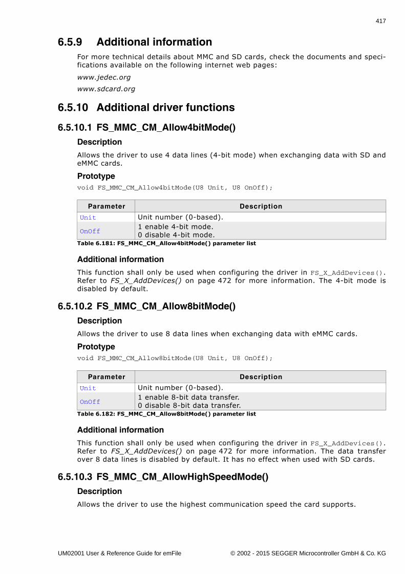
417
6.5.9 Additional informationFor more technical details about MMC and SD cards, check the documents and speci-fications available on the following internet web pages:
www.jedec.org
www.sdcard.org
6.5.10 Additional driver functions
6.5.10.1 FS_MMC_CM_Allow4bitMode()Description
Allows the driver to use 4 data lines (4-bit mode) when exchanging data with SD andeMMC cards.
Prototypevoid FS_MMC_CM_Allow4bitMode(U8 Unit, U8 OnOff);
Additional information
This function shall only be used when configuring the driver in FS_X_AddDevices().Refer to FS_X_AddDevices() on page 472 for more information. The 4-bit mode isdisabled by default.
6.5.10.2 FS_MMC_CM_Allow8bitMode()Description
Allows the driver to use 8 data lines when exchanging data with eMMC cards.
Prototypevoid FS_MMC_CM_Allow8bitMode(U8 Unit, U8 OnOff);
Additional information
This function shall only be used when configuring the driver in FS_X_AddDevices().Refer to FS_X_AddDevices() on page 472 for more information. The data transferover 8 data lines is disabled by default. It has no effect when used with SD cards.
6.5.10.3 FS_MMC_CM_AllowHighSpeedMode()Description
Allows the driver to use the highest communication speed the card supports.
Parameter Description
Unit Unit number (0-based).
OnOff1 enable 4-bit mode.0 disable 4-bit mode.
Table 6.181: FS_MMC_CM_Allow4bitMode() parameter list
Parameter Description
Unit Unit number (0-based).
OnOff1 enable 8-bit data transfer.0 disable 8-bit data transfer.
Table 6.182: FS_MMC_CM_Allow8bitMode() parameter list
UM02001 User & Reference Guide for emFile © 2002 - 2015 SEGGER Microcontroller GmbH & Co. KG
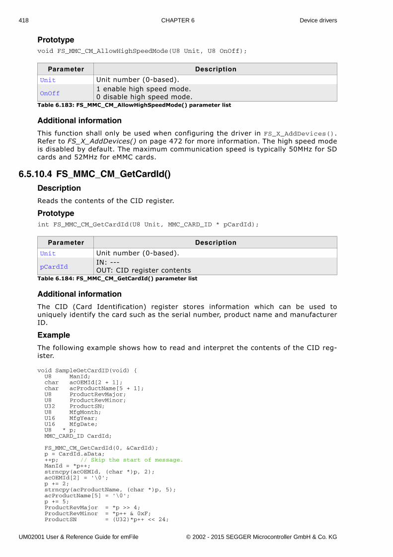
418 CHAPTER 6 Device drivers
Prototypevoid FS_MMC_CM_AllowHighSpeedMode(U8 Unit, U8 OnOff);
Additional information
This function shall only be used when configuring the driver in FS_X_AddDevices().Refer to FS_X_AddDevices() on page 472 for more information. The high speed modeis disabled by default. The maximum communication speed is typically 50MHz for SDcards and 52MHz for eMMC cards.
6.5.10.4 FS_MMC_CM_GetCardId()Description
Reads the contents of the CID register.
Prototypeint FS_MMC_CM_GetCardId(U8 Unit, MMC_CARD_ID * pCardId);
Additional information
The CID (Card Identification) register stores information which can be used touniquely identify the card such as the serial number, product name and manufacturerID.
Example
The following example shows how to read and interpret the contents of the CID reg-ister.
void SampleGetCardID(void) { U8 ManId; char acOEMId[2 + 1]; char acProductName[5 + 1]; U8 ProductRevMajor; U8 ProductRevMinor; U32 ProductSN; U8 MfgMonth; U16 MfgYear; U16 MfgDate; U8 * p; MMC_CARD_ID CardId;
FS_MMC_CM_GetCardId(0, &CardId); p = CardId.aData; ++p; // Skip the start of message. ManId = *p++; strncpy(acOEMId, (char *)p, 2); acOEMId[2] = '\0'; p += 2; strncpy(acProductName, (char *)p, 5); acProductName[5] = '\0'; p += 5; ProductRevMajor = *p >> 4; ProductRevMinor = *p++ & 0xF; ProductSN = (U32)*p++ << 24;
Parameter Description
Unit Unit number (0-based).
OnOff1 enable high speed mode.0 disable high speed mode.
Table 6.183: FS_MMC_CM_AllowHighSpeedMode() parameter list
Parameter Description
Unit Unit number (0-based).
pCardIdIN: ---OUT: CID register contents
Table 6.184: FS_MMC_CM_GetCardId() parameter list
UM02001 User & Reference Guide for emFile © 2002 - 2015 SEGGER Microcontroller GmbH & Co. KG
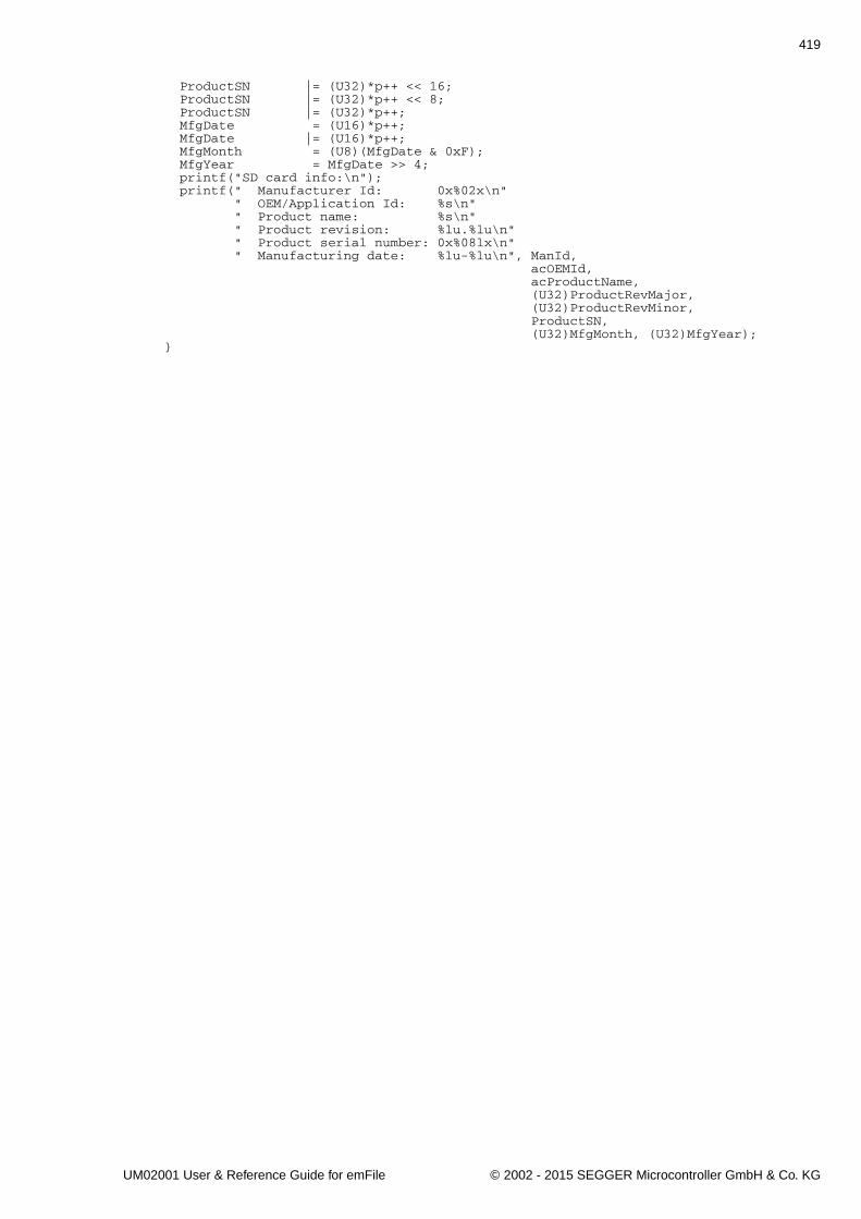
419
ProductSN |= (U32)*p++ << 16; ProductSN |= (U32)*p++ << 8; ProductSN |= (U32)*p++; MfgDate = (U16)*p++; MfgDate |= (U16)*p++; MfgMonth = (U8)(MfgDate & 0xF); MfgYear = MfgDate >> 4; printf("SD card info:\n"); printf(" Manufacturer Id: 0x%02x\n" " OEM/Application Id: %s\n" " Product name: %s\n" " Product revision: %lu.%lu\n" " Product serial number: 0x%08lx\n" " Manufacturing date: %lu-%lu\n", ManId, acOEMId, acProductName, (U32)ProductRevMajor, (U32)ProductRevMinor, ProductSN, (U32)MfgMonth, (U32)MfgYear);}
UM02001 User & Reference Guide for emFile © 2002 - 2015 SEGGER Microcontroller GmbH & Co. KG
420 CHAPTER 6 Device drivers
6.5.11 Performance and resource usage
6.5.11.1 ROM usageThe ROM usage depends on the compiler options, the compiler version and the usedCPU. The memory requirements of the MMC/SD driver have been measured on a sys-tem as follows: ARM7, IAR Embedded workbench V4.41A, Thumb mode, Size optimi-zation.
6.5.11.2 Static RAM usageStatic RAM usage is the amount of RAM required by the driver for variables inside ofthe driver. The number of bytes can be seen in a compiler list file
Static RAM usage of the SD card driver in SPI mode: 12 bytesStatic RAM usage of the SD card driver in card mode: 12 bytes
6.5.11.3 PerformanceThese performance measurements are in no way complete, but they give an approxi-mation of the length of time required for common operations on various targets. Thetests were performed as described in Performance on page 502.
All values are in Mbytes/sec.
6.5.12 TroubleshootingIf the driver test fails or if the card cannot be accessed at all, please follow the trou-ble shooting guidelines below.
6.5.12.1 SPI mode troubleshooting guideVerify SPI configuration
If an SPI is used, you should verify that it is set up as follows:
� 8 bits per transfer� Most significant bit first� Data changes on falling edge� Data is sampled on rising edge.
ModuleROM
[Kbytes]
emFile SD card SPI mode driver 2.8emFile SD card mode driver 3.9
DeviceCPU
speedMedium W R
Atmel AT91SAM7S 48 MHz MMC/SD using SPI with 24MHz 2.3 2.3
Atmel AT91SAM9261 178 MHz MMC/SD driver using SPI with 24 MHz. 2.3 2.5
Atmel AT91SAM9263 200 MHz MMC/SD card mode driver using card controller with 25 MHz. 10.0 9.3
LogicPD LH79520 51 MHz MMC using SPI with 12MHz 0.5 1.3
NXP LPC2478 57 MHz MMC/SD card mode driver using card controller with 25 MHz. 2.4 3.1
NXP LPC3250 208 MHz MMC/SD card mode driver using card controller with 25 MHz. 3.9 8.4
Toshiba TMPA910 192 MHz MMC/SD card mode driver using card controller with 25 MHz. 3.9 8.4
Table 6.185: Performance values for sample configurations
UM02001 User & Reference Guide for emFile © 2002 - 2015 SEGGER Microcontroller GmbH & Co. KG
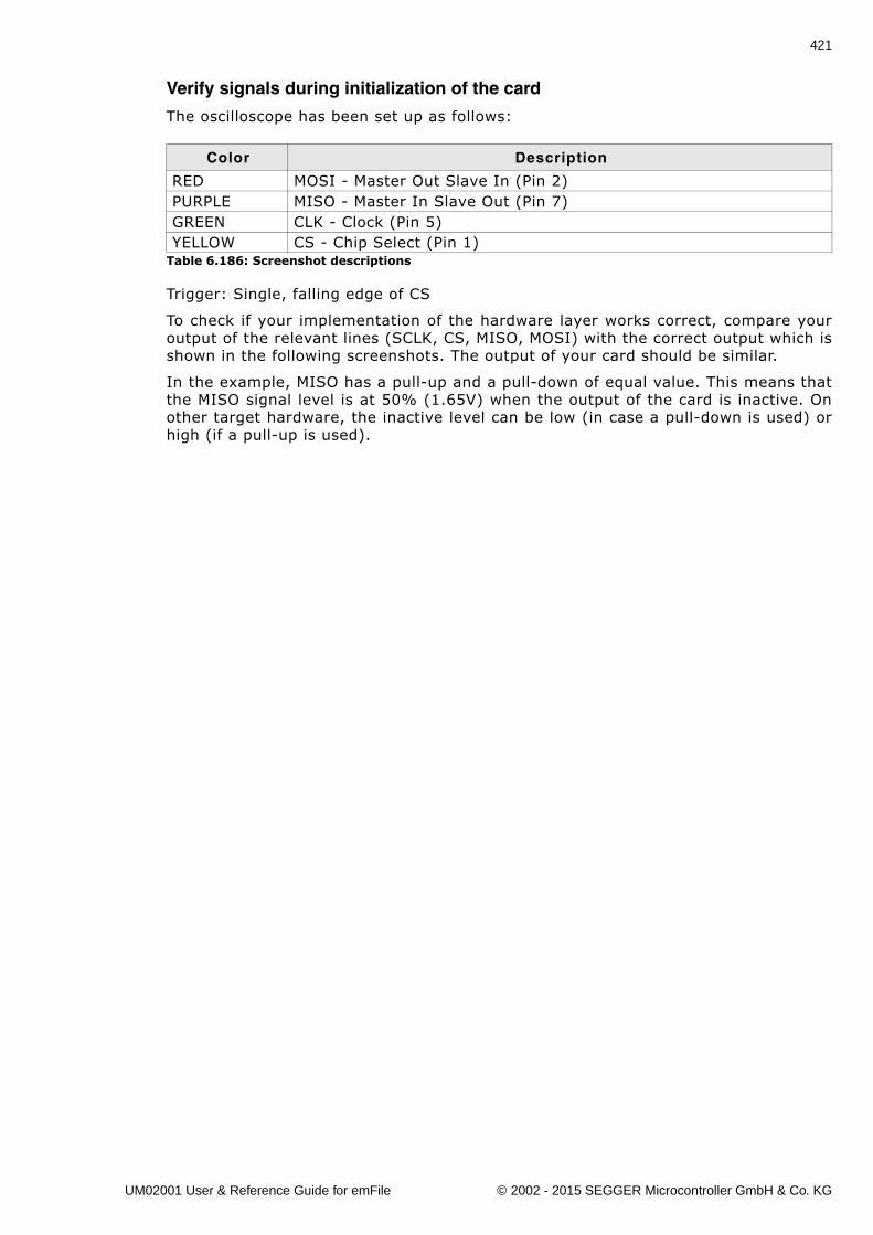
421
Verify signals during initialization of the card
The oscilloscope has been set up as follows:
Trigger: Single, falling edge of CS
To check if your implementation of the hardware layer works correct, compare youroutput of the relevant lines (SCLK, CS, MISO, MOSI) with the correct output which isshown in the following screenshots. The output of your card should be similar.
In the example, MISO has a pull-up and a pull-down of equal value. This means thatthe MISO signal level is at 50% (1.65V) when the output of the card is inactive. Onother target hardware, the inactive level can be low (in case a pull-down is used) orhigh (if a pull-up is used).
Color Description
RED MOSI - Master Out Slave In (Pin 2)PURPLE MISO - Master In Slave Out (Pin 7)GREEN CLK - Clock (Pin 5)YELLOW CS - Chip Select (Pin 1)
Table 6.186: Screenshot descriptions
UM02001 User & Reference Guide for emFile © 2002 - 2015 SEGGER Microcontroller GmbH & Co. KG
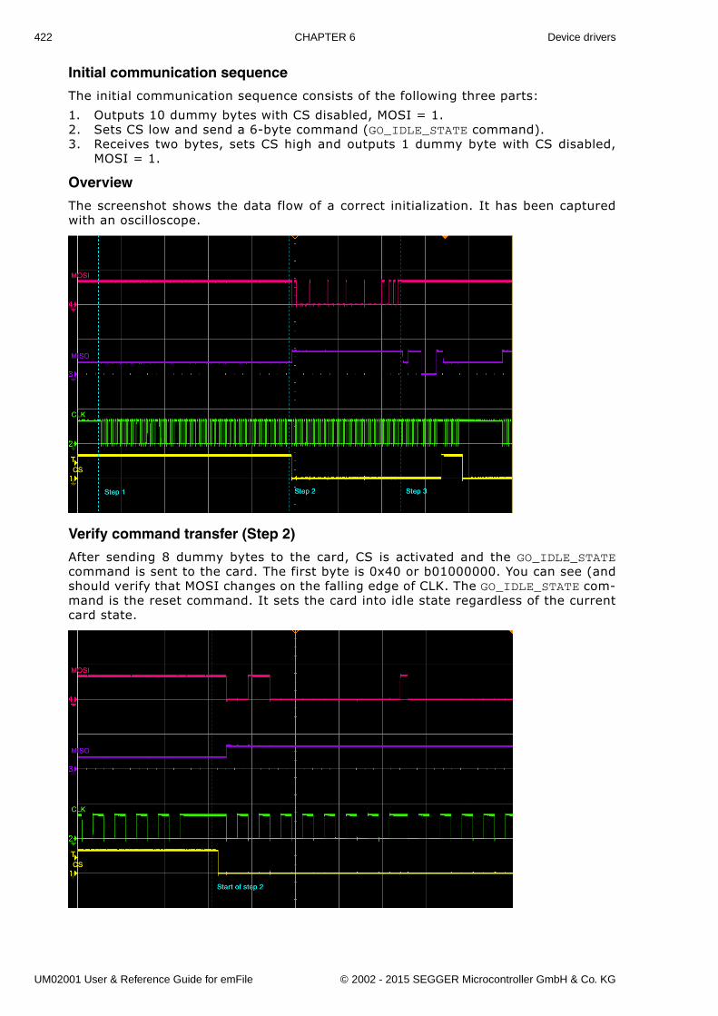
422 CHAPTER 6 Device drivers
Initial communication sequence
The initial communication sequence consists of the following three parts:
1. Outputs 10 dummy bytes with CS disabled, MOSI = 1.2. Sets CS low and send a 6-byte command (GO_IDLE_STATE command).3. Receives two bytes, sets CS high and outputs 1 dummy byte with CS disabled,
MOSI = 1.
Overview
The screenshot shows the data flow of a correct initialization. It has been capturedwith an oscilloscope.
Verify command transfer (Step 2)
After sending 8 dummy bytes to the card, CS is activated and the GO_IDLE_STATEcommand is sent to the card. The first byte is 0x40 or b01000000. You can see (andshould verify that MOSI changes on the falling edge of CLK. The GO_IDLE_STATE com-mand is the reset command. It sets the card into idle state regardless of the currentcard state.
UM02001 User & Reference Guide for emFile © 2002 - 2015 SEGGER Microcontroller GmbH & Co. KG
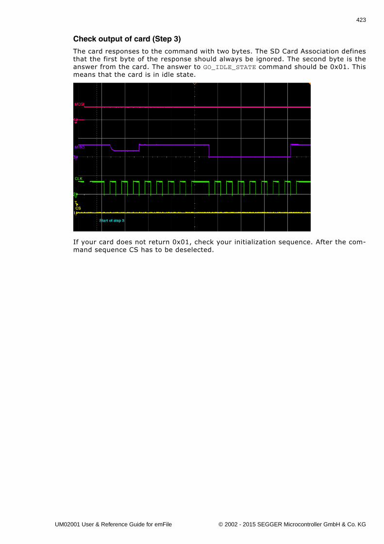
423
Check output of card (Step 3)
The card responses to the command with two bytes. The SD Card Association definesthat the first byte of the response should always be ignored. The second byte is theanswer from the card. The answer to GO_IDLE_STATE command should be 0x01. Thismeans that the card is in idle state.
If your card does not return 0x01, check your initialization sequence. After the com-mand sequence CS has to be deselected.
UM02001 User & Reference Guide for emFile © 2002 - 2015 SEGGER Microcontroller GmbH & Co. KG
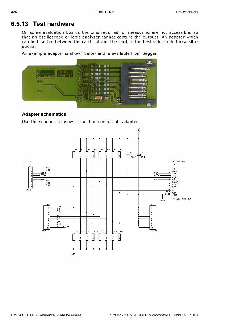
424 CHAPTER 6 Device drivers
6.5.13 Test hardwareOn some evaluation boards the pins required for measuring are not accessible, sothat an oscilloscope or logic analyzer cannot capture the outputs. An adapter whichcan be inserted between the card slot and the card, is the best solution in those situ-ations.
An example adapter is shown below and is available from Segger.
Adapter schematics
Use the schematic below to build an compatible adapter.
UM02001 User & Reference Guide for emFile © 2002 - 2015 SEGGER Microcontroller GmbH & Co. KG
425
6.6 CompactFlash card and IDE driveremFile supports the use of CompactFlash & IDE devices. An optional generic driverfor CompactFlash & IDE devices is available.
To use the driver with your specific hardware, you will have to provide basic I/O func-tions for accessing the ATA I/O registers. This section describes all these routines.
6.6.1 Supported HardwareemFile's CompactFlash & IDE device driver can be used to access most ATA HD drivesor CompactFlash storage cards also known as CF using true IDE or Memory cardmode.
UM02001 User & Reference Guide for emFile © 2002 - 2015 SEGGER Microcontroller GmbH & Co. KG
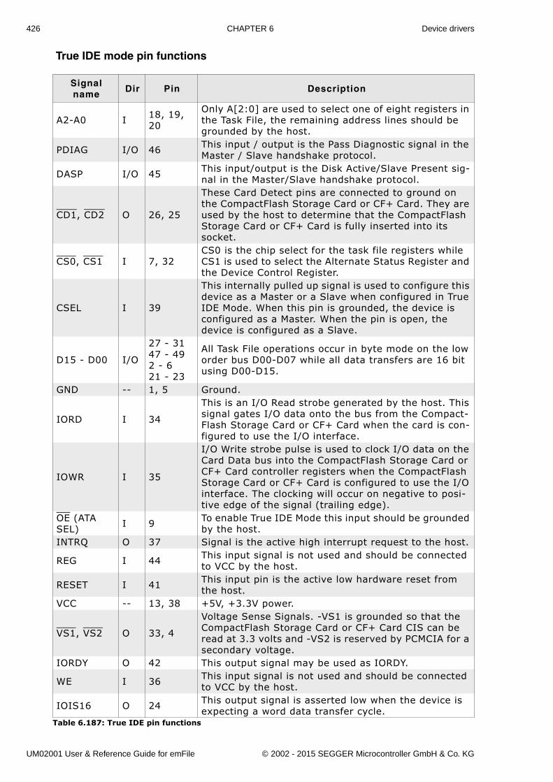
426 CHAPTER 6 Device drivers
True IDE mode pin functions
Signal name
Dir Pin Description
A2-A0 I 18, 19, 20
Only A[2:0] are used to select one of eight registers in the Task File, the remaining address lines should be grounded by the host.
PDIAG I/O 46 This input / output is the Pass Diagnostic signal in the Master / Slave handshake protocol.
DASP I/O 45 This input/output is the Disk Active/Slave Present sig-nal in the Master/Slave handshake protocol.
CD1, CD2 O 26, 25
These Card Detect pins are connected to ground on the CompactFlash Storage Card or CF+ Card. They are used by the host to determine that the CompactFlash Storage Card or CF+ Card is fully inserted into its socket.
CS0, CS1 I 7, 32CS0 is the chip select for the task file registers while CS1 is used to select the Alternate Status Register and the Device Control Register.
CSEL I 39
This internally pulled up signal is used to configure this device as a Master or a Slave when configured in True IDE Mode. When this pin is grounded, the device is configured as a Master. When the pin is open, the device is configured as a Slave.
D15 - D00 I/O
27 - 3147 - 492 - 621 - 23
All Task File operations occur in byte mode on the low order bus D00-D07 while all data transfers are 16 bit using D00-D15.
GND -- 1, 5 Ground.
IORD I 34
This is an I/O Read strobe generated by the host. This signal gates I/O data onto the bus from the Compact-Flash Storage Card or CF+ Card when the card is con-figured to use the I/O interface.
IOWR I 35
I/O Write strobe pulse is used to clock I/O data on the Card Data bus into the CompactFlash Storage Card or CF+ Card controller registers when the CompactFlash Storage Card or CF+ Card is configured to use the I/O interface. The clocking will occur on negative to posi-tive edge of the signal (trailing edge).
OE (ATA SEL) I 9 To enable True IDE Mode this input should be grounded
by the host.INTRQ O 37 Signal is the active high interrupt request to the host.
REG I 44 This input signal is not used and should be connected to VCC by the host.
RESET I 41 This input pin is the active low hardware reset from the host.
VCC -- 13, 38 +5V, +3.3V power.
VS1, VS2 O 33, 4
Voltage Sense Signals. -VS1 is grounded so that the CompactFlash Storage Card or CF+ Card CIS can be read at 3.3 volts and -VS2 is reserved by PCMCIA for a secondary voltage.
IORDY O 42 This output signal may be used as IORDY.
WE I 36 This input signal is not used and should be connected to VCC by the host.
IOIS16 O 24 This output signal is asserted low when the device is expecting a word data transfer cycle.
Table 6.187: True IDE pin functions
UM02001 User & Reference Guide for emFile © 2002 - 2015 SEGGER Microcontroller GmbH & Co. KG
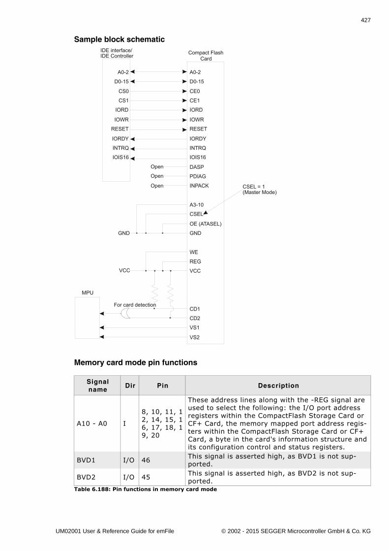
427
Sample block schematic
Memory card mode pin functions
Signal name
Dir Pin Description
A10 - A0 I
8, 10, 11, 12, 14, 15, 16, 17, 18, 19, 20
These address lines along with the -REG signal are used to select the following: the I/O port address registers within the CompactFlash Storage Card or CF+ Card, the memory mapped port address regis-ters within the CompactFlash Storage Card or CF+ Card, a byte in the card's information structure and its configuration control and status registers.
BVD1 I/O 46 This signal is asserted high, as BVD1 is not sup-ported.
BVD2 I/O 45 This signal is asserted high, as BVD2 is not sup-ported.
Table 6.188: Pin functions in memory card mode
MPU
Open
Open
Open
GND
VCC
For card detection
IDE interface/IDE Controller
A0-2
D0-15
CS0
CS1
IORD
IOWR
RESET
IORDY
INTRQ
IOIS16
A0-2
D0-15
CE0
CE1
IORD
IOWR
RESET
IORDY
INTRQ
IOIS16
DASP
PDIAG
INPACK
A3-10
CSEL
OE (ATASEL)
GND
WE
REG
VCC
CD1
CD2
VS1
VS2
Compact FlashCard
CSEL = 1(Master Mode)
UM02001 User & Reference Guide for emFile © 2002 - 2015 SEGGER Microcontroller GmbH & Co. KG
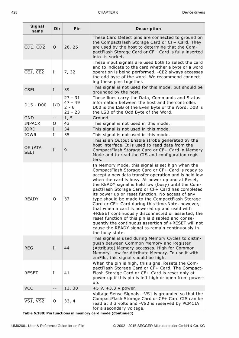
428 CHAPTER 6 Device drivers
CD1, CD2 O 26, 25
These Card Detect pins are connected to ground on the CompactFlash Storage Card or CF+ Card. They are used by the host to determine that the Com-pactFlash Storage Card or CF+ Card is fully inserted into its socket.
CE1, CE2 I 7, 32
These input signals are used both to select the card and to indicate to the card whether a byte or a word operation is being performed. -CE2 always accesses the odd byte of the word. We recommend connect-ing these pins together.
CSEL I 39 This signal is not used for this mode, but should be grounded by the host.
D15 - D00 I/O
27 - 3147 - 492 - 621 - 23
These lines carry the Data, Commands and Status information between the host and the controller. D00 is the LSB of the Even Byte of the Word. D08 is the LSB of the Odd Byte of the Word.
GND -- 1, 5 Ground.INPACK O 43 This signal is not used in this mode.IORD I 34 This signal is not used in this mode.IOWR I 35 This signal is not used in this mode.
OE (ATA SEL) I 9
This is an Output Enable strobe generated by the host interface. It is used to read data from the CompactFlash Storage Card or CF+ Card in Memory Mode and to read the CIS and configuration regis-ters.
READY O 37
In Memory Mode, this signal is set high when the CompactFlash Storage Card or CF+ Card is ready to accept a new data transfer operation and is held low when the card is busy. At power up and at Reset, the READY signal is held low (busy) until the Com-pactFlash Storage Card or CF+ Card has completed its power up or reset function. No access of any type should be made to the CompactFlash Storage Card or CF+ Card during this time.Note, however, that when a card is powered up and used with +RESET continuously disconnected or asserted, the reset function of this pin is disabled and conse-quently the continuous assertion of +RESET will not cause the READY signal to remain continuously in the busy state.
REG I 44
This signal is used during Memory Cycles to distin-guish between Common Memory and Register (Attribute) Memory accesses. High for Common Memory, Low for Attribute Memory. To use it with emFile, this signal should be high.
RESET I 41
When the pin is high, this signal Resets the Com-pactFlash Storage Card or CF+ Card. The Compact-Flash Storage Card or CF+ Card is reset only at power up if this pin is left high or open from power-up.
VCC -- 13, 38 +5 V, +3.3 V power.
VS1, VS2 O 33, 4
Voltage Sense Signals. -VS1 is grounded so that the CompactFlash Storage Card or CF+ Card CIS can be read at 3.3 volts and -VS2 is reserved by PCMCIA for a secondary voltage.
Signal name
Dir Pin Description
Table 6.188: Pin functions in memory card mode (Continued)
UM02001 User & Reference Guide for emFile © 2002 - 2015 SEGGER Microcontroller GmbH & Co. KG
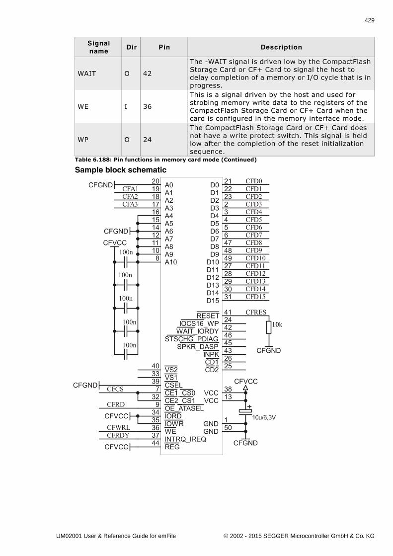
429
Sample block schematic
WAIT O 42
The -WAIT signal is driven low by the CompactFlash Storage Card or CF+ Card to signal the host to delay completion of a memory or I/O cycle that is in progress.
WE I 36
This is a signal driven by the host and used for strobing memory write data to the registers of the CompactFlash Storage Card or CF+ Card when the card is configured in the memory interface mode.
WP O 24
The CompactFlash Storage Card or CF+ Card does not have a write protect switch. This signal is held low after the completion of the reset initialization sequence.
Signal name
Dir Pin Description
Table 6.188: Pin functions in memory card mode (Continued)
CFVCC
A020
A119
A218
A317
A416
A515
A614
A712
A811
A910
A108
D0 21
D1 22
D2 23
D3 2
D4 3
D5 4
D6D7 6
D8 47
D9 48
D10 49
D11 27
D12 28
D13 29
D14 30
D15 31
GND 50GND 1
VS133 VS240
VCC 13VCC 38
CD2 25CD1 26
CE1_CS07
CE2_CS132
OE_ATASEL9
WE36
RESET 41
REG44 INTRQ_IREQ37
IOCS16_WP 24
WAIT_IORDY 42
STSCHG_PDIAG 46
SPKR_DASP 45
IORD34
IOWR35
INPK 43
CSEL39
10u/6,3V
CFGND
CFA1CFA2CFA3
CFRD
CFWRL
CFCS
CFGND
CFGND
CFVCC
CFVCC
CFGND
CFRDY
CFRES
CFD0CFD1CFD2CFD3CFD4CFD5CFD6CFD7CFD8CFD9CFD10CFD11CFD12CFD13CFD14CFD15
100n
100n
100n
CFVCC
1010k
CFGND
5
UM02001 User & Reference Guide for emFile © 2002 - 2015 SEGGER Microcontroller GmbH & Co. KG
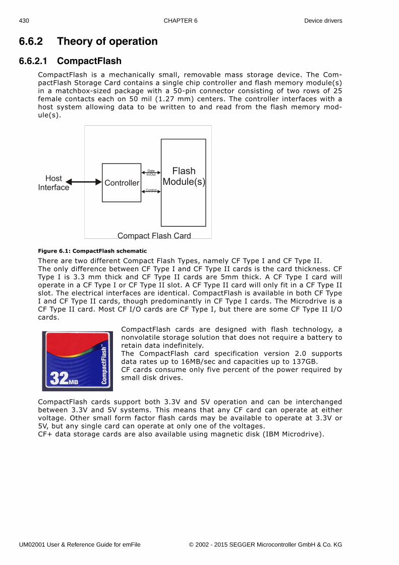
430 CHAPTER 6 Device drivers
6.6.2 Theory of operation
6.6.2.1 CompactFlashCompactFlash is a mechanically small, removable mass storage device. The Com-pactFlash Storage Card contains a single chip controller and flash memory module(s)in a matchbox-sized package with a 50-pin connector consisting of two rows of 25female contacts each on 50 mil (1.27 mm) centers. The controller interfaces with ahost system allowing data to be written to and read from the flash memory mod-ule(s).
Figure 6.1: CompactFlash schematic
There are two different Compact Flash Types, namely CF Type I and CF Type II.The only difference between CF Type I and CF Type II cards is the card thickness. CFType I is 3.3 mm thick and CF Type II cards are 5mm thick. A CF Type I card willoperate in a CF Type I or CF Type II slot. A CF Type II card will only fit in a CF Type IIslot. The electrical interfaces are identical. CompactFlash is available in both CF TypeI and CF Type II cards, though predominantly in CF Type I cards. The Microdrive is aCF Type II card. Most CF I/O cards are CF Type I, but there are some CF Type II I/Ocards.
CompactFlash cards are designed with flash technology, anonvolatile storage solution that does not require a battery toretain data indefinitely.The CompactFlash card specification version 2.0 supportsdata rates up to 16MB/sec and capacities up to 137GB.CF cards consume only five percent of the power required bysmall disk drives.
CompactFlash cards support both 3.3V and 5V operation and can be interchangedbetween 3.3V and 5V systems. This means that any CF card can operate at eithervoltage. Other small form factor flash cards may be available to operate at 3.3V or5V, but any single card can operate at only one of the voltages.CF+ data storage cards are also available using magnetic disk (IBM Microdrive).
ControllerFlash
Module(s)Control
DataIn/Out
Compact Flash Card
HostInterface
UM02001 User & Reference Guide for emFile © 2002 - 2015 SEGGER Microcontroller GmbH & Co. KG
431
Modes of operation (interface modes)
Compact Flash cards can operate in three modes:
� Memory card mode� I/O Card mode� True IDE mode
Supported modes of operation (interface modes)
Currently, TRUE IDE and MEMORY CARD mode are supported.
UM02001 User & Reference Guide for emFile © 2002 - 2015 SEGGER Microcontroller GmbH & Co. KG

432 CHAPTER 6 Device drivers
Memory card mode pin functions
Signal name
Dir Pin Description
A10 - A0 I
8, 10, 11, 12, 14, 15, 16, 17, 18, 19, 20
These address lines along with the -REG signal are used to select the following: the I/O port address registers within the CompactFlash Storage Card or CF+ Card, the memory mapped port address regis-ters within the CompactFlash Storage Card or CF+ Card, a byte in the card's information structure and its configuration control and status registers.
BVD1 I/O 46 This signal is asserted high, as BVD1 is not sup-ported.
BVD2 I/O 45 This signal is asserted high, as BVD2 is not sup-ported.
CD1, CD2 O 26, 25
These Card Detect pins are connected to ground on the CompactFlash Storage Card or CF+ Card. They are used by the host to determine that the Com-pactFlash Storage Card or CF+ Card is fully inserted into its socket.
CE1, CE2 I 7, 32
These input signals are used both to select the card and to indicate to the card whether a byte or a word operation is being performed. -CE2 always accesses the odd byte of the word. We recommend connect-ing these pins together.
CSEL I 39 This signal is not used for this mode, but should be grounded by the host.
D15 - D00 I/O
27 - 3147 - 492 - 621 - 23
These lines carry the Data, Commands and Status information between the host and the controller. D00 is the LSB of the Even Byte of the Word. D08 is the LSB of the Odd Byte of the Word.
GND -- 1, 5 Ground.INPACK O 43 This signal is not used in this mode.IORD I 34 This signal is not used in this mode.IOWR I 35 This signal is not used in this mode.
OE (ATA SEL) I 9
This is an Output Enable strobe generated by the host interface. It is used to read data from the CompactFlash Storage Card or CF+ Card in Memory Mode and to read the CIS and configuration regis-ters.
READY O 37
In Memory Mode, this signal is set high when the CompactFlash Storage Card or CF+ Card is ready to accept a new data transfer operation and is held low when the card is busy. At power up and at Reset, the READY signal is held low (busy) until the Com-pactFlash Storage Card or CF+ Card has completed its power up or reset function. No access of any type should be made to the CompactFlash Storage Card or CF+ Card during this time.Note, however, that when a card is powered up and used with +RESET continuously disconnected or asserted, the reset function of this pin is disabled and conse-quently the continuous assertion of +RESET will not cause the READY signal to remain continuously in the busy state.
Table 6.189: Pin functions in memory card mode
UM02001 User & Reference Guide for emFile © 2002 - 2015 SEGGER Microcontroller GmbH & Co. KG
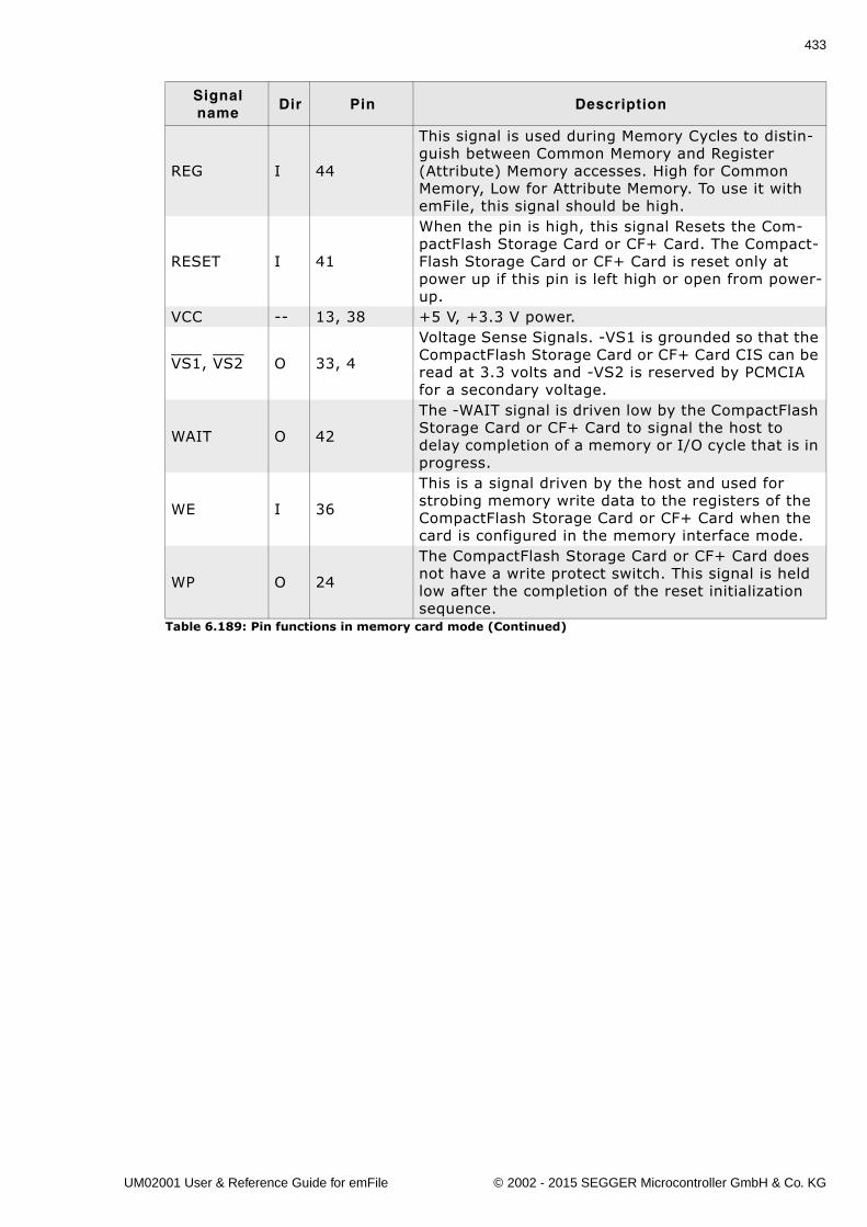
433
REG I 44
This signal is used during Memory Cycles to distin-guish between Common Memory and Register (Attribute) Memory accesses. High for Common Memory, Low for Attribute Memory. To use it with emFile, this signal should be high.
RESET I 41
When the pin is high, this signal Resets the Com-pactFlash Storage Card or CF+ Card. The Compact-Flash Storage Card or CF+ Card is reset only at power up if this pin is left high or open from power-up.
VCC -- 13, 38 +5 V, +3.3 V power.
VS1, VS2 O 33, 4
Voltage Sense Signals. -VS1 is grounded so that the CompactFlash Storage Card or CF+ Card CIS can be read at 3.3 volts and -VS2 is reserved by PCMCIA for a secondary voltage.
WAIT O 42
The -WAIT signal is driven low by the CompactFlash Storage Card or CF+ Card to signal the host to delay completion of a memory or I/O cycle that is in progress.
WE I 36
This is a signal driven by the host and used for strobing memory write data to the registers of the CompactFlash Storage Card or CF+ Card when the card is configured in the memory interface mode.
WP O 24
The CompactFlash Storage Card or CF+ Card does not have a write protect switch. This signal is held low after the completion of the reset initialization sequence.
Signal name
Dir Pin Description
Table 6.189: Pin functions in memory card mode (Continued)
UM02001 User & Reference Guide for emFile © 2002 - 2015 SEGGER Microcontroller GmbH & Co. KG
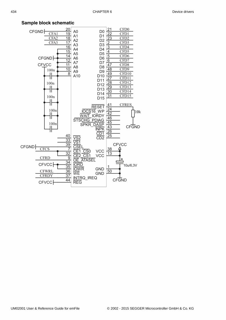
434 CHAPTER 6 Device drivers
Sample block schematic
CFVCC
A020
A119
A218
A317
A416
A515
A614
A712
A811
A910
A108
D0 21
D1 22
D2 23
D3 2
D4 3
D5 4
D6D7 6
D8 47
D9 48
D10 49
D11 27
D12 28
D13 29
D14 30
D15 31
GND 50GND 1
VS133 VS240
VCC 13VCC 38
CD2 25CD1 26
CE1_CS07
CE2_CS132
OE_ATASEL9
WE36
RESET 41
REG44 INTRQ_IREQ37
IOCS16_WP 24
WAIT_IORDY 42
STSCHG_PDIAG 46
SPKR_DASP 45
IORD34
IOWR35
INPK 43
CSEL39
10u/6,3V
CFGND
CFA1CFA2CFA3
CFRD
CFWRL
CFCS
CFGND
CFGND
CFVCC
CFVCC
CFGND
CFRDY
CFRES
CFD0CFD1CFD2CFD3CFD4CFD5CFD6CFD7CFD8CFD9CFD10CFD11CFD12CFD13CFD14CFD15
100n
100n
100n
CFVCC
1010k
CFGND
5
UM02001 User & Reference Guide for emFile © 2002 - 2015 SEGGER Microcontroller GmbH & Co. KG
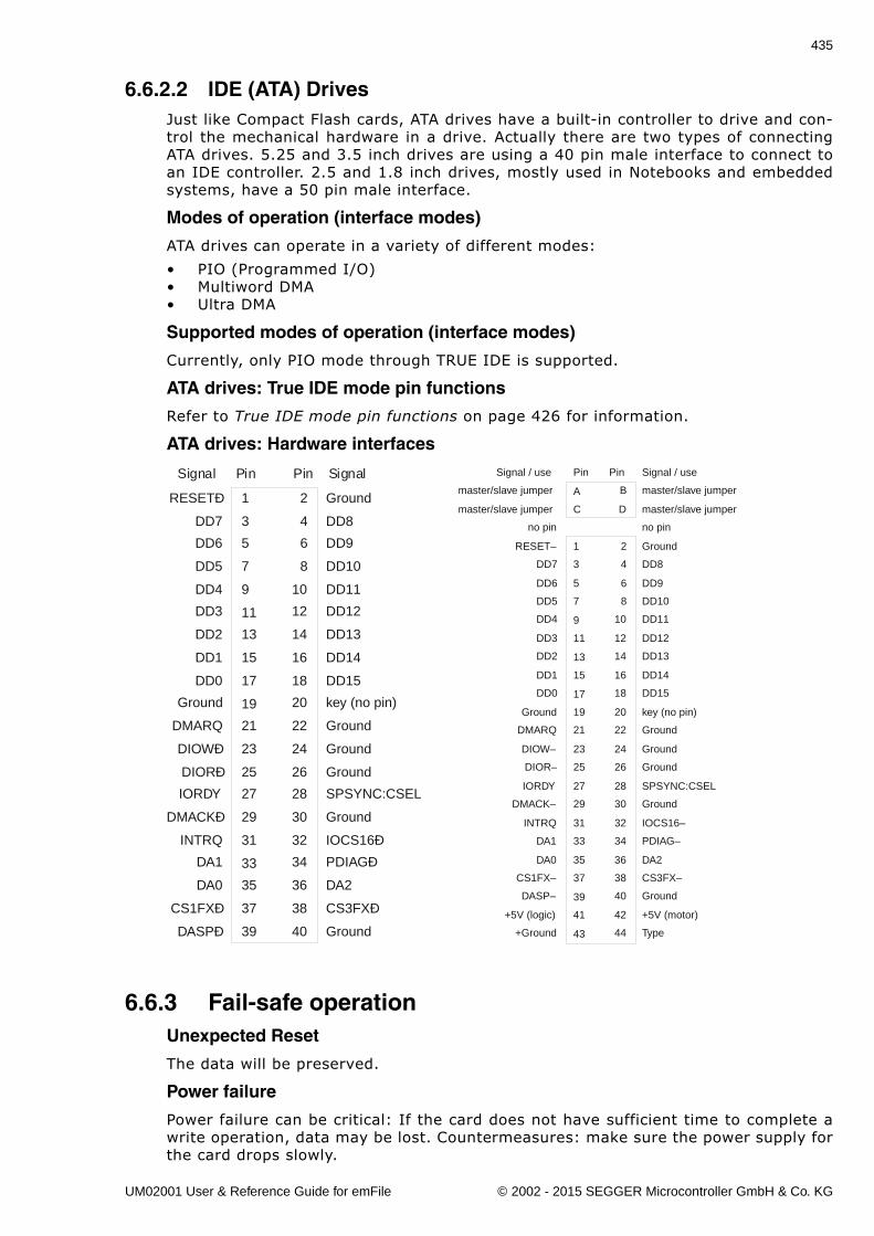
435
6.6.2.2 IDE (ATA) DrivesJust like Compact Flash cards, ATA drives have a built-in controller to drive and con-trol the mechanical hardware in a drive. Actually there are two types of connectingATA drives. 5.25 and 3.5 inch drives are using a 40 pin male interface to connect toan IDE controller. 2.5 and 1.8 inch drives, mostly used in Notebooks and embeddedsystems, have a 50 pin male interface.
Modes of operation (interface modes)
ATA drives can operate in a variety of different modes:
� PIO (Programmed I/O)� Multiword DMA� Ultra DMA
Supported modes of operation (interface modes)
Currently, only PIO mode through TRUE IDE is supported.
ATA drives: True IDE mode pin functions
Refer to True IDE mode pin functions on page 426 for information.
ATA drives: Hardware interfaces
6.6.3 Fail-safe operationUnexpected Reset
The data will be preserved.
Power failure
Power failure can be critical: If the card does not have sufficient time to complete awrite operation, data may be lost. Countermeasures: make sure the power supply forthe card drops slowly.
1
3
5
7
9
11
13
15
17
19
21
23
25
27
29
31
33
35
37
39
2
4
6
8
10
12
14
16
18
20
22
24
26
28
30
32
34
36
38
40
Ground
DD8
DD9
DD10
DD11
DD12
DD13
DD14
DD15
key (no pin)
Ground
Ground
Ground
SPSYNC:CSEL
Ground
IOCS16Ð
PDIAGÐ
DA2
CS3FXÐ
Ground
Pin Pin SignalSignal
RESETÐ
DD7
DD6
DD5
DD4
DD3
DD2
DD1
DD0
Ground
DMARQ
DIOWÐ
DIORÐ
IORDY
DMACKÐ
INTRQ
DA1
DA0
CS1FXÐ
DASPÐ
Pin
A
C
1
3
5
7
9
11
13
15
17
19
21
23
25
27
29
31
33
35
37
39
41
43
Pin
B
D
2
4
6
8
10
12
14
16
18
20
22
24
26
28
30
32
34
36
38
40
42
44
Signal / use
master/slave jumper
master/slave jumper
no pin
Ground
DD8
DD9
DD10
DD11
DD12
DD13
DD14
DD15
key (no pin)
Ground
Ground
Ground
SPSYNC:CSEL
Ground
IOCS16–
PDIAG–
DA2
CS3FX–
Ground
+5V (motor)
Type
Signal / use
master/slave jumper
master/slave jumper
no pin
RESET–
DD7
DD6
DD5
DD4
DD3
DD2
DD1
DD0
Ground
DMARQ
DIOW–
DIOR–
IORDY
DMACK–
INTRQ
DA1
DA0
CS1FX–
DASP–
+5V (logic)
+Ground
UM02001 User & Reference Guide for emFile © 2002 - 2015 SEGGER Microcontroller GmbH & Co. KG
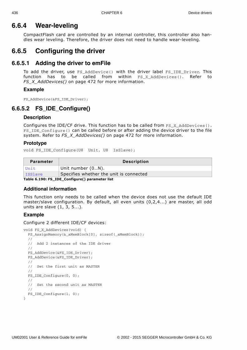
436 CHAPTER 6 Device drivers
6.6.4 Wear-levelingCompactFlash card are controlled by an internal controller, this controller also han-dles wear leveling. Therefore, the driver does not need to handle wear-leveling.
6.6.5 Configuring the driver
6.6.5.1 Adding the driver to emFileTo add the driver, use FS_AddDevice() with the driver label FS_IDE_Driver. Thisfunction has to be called from within FS_X_AddDevices(). Refer toFS_X_AddDevices() on page 472 for more information.
Example
FS_AddDevice(&FS_IDE_Driver);
6.6.5.2 FS_IDE_Configure()Description
Configures the IDE/CF drive. This function has to be called from FS_X_AddDevices().FS_IDE_Configure() can be called before or after adding the device driver to the filesystem. Refer to FS_X_AddDevices() on page 472 for more information.
Prototypevoid FS_IDE_Configure(U8 Unit, U8 IsSlave);
Additional information
This function only needs to be called when the device does not use the default IDEmaster/slave configuration. By default, all even units (0,2,4...) are master, all oddunits are slave (1, 3, 5...).
Example
Configure 2 different IDE/CF devices:
void FS_X_AddDevices(void) { FS_AssignMemory(&_aMemBlock[0], sizeof(_aMemBlock)); // // Add 2 instances of the IDE driver // FS_AddDevice(&FS_IDE_Driver); FS_AddDevice(&FS_IDE_Driver); // // Set the first unit as MASTER // FS_IDE_Configure(0, 0); // // Set the second unit as MASTER // FS_IDE_Configure(1, 0);}
Parameter Description
Unit Unit number (0�N).ISSlave Specifies whether the unit is connected
Table 6.190: FS_IDE_Configure() parameter list
UM02001 User & Reference Guide for emFile © 2002 - 2015 SEGGER Microcontroller GmbH & Co. KG
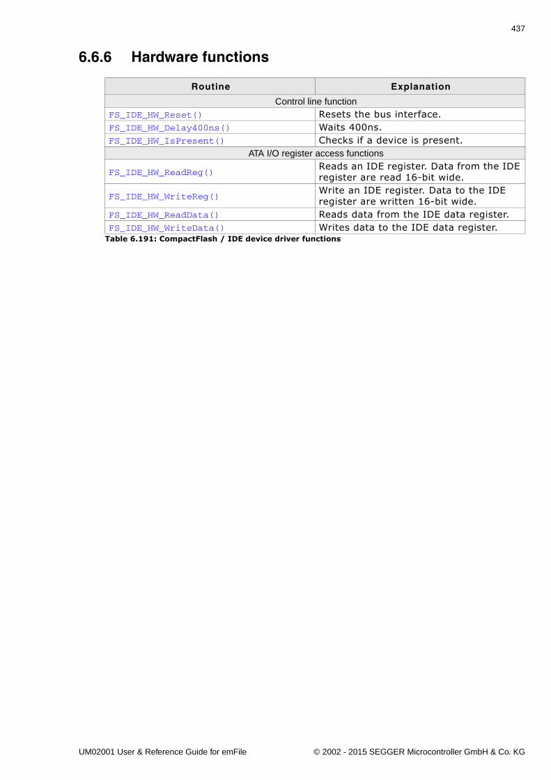
437
6.6.6 Hardware functions
Routine Explanation
Control line functionFS_IDE_HW_Reset() Resets the bus interface.FS_IDE_HW_Delay400ns() Waits 400ns.FS_IDE_HW_IsPresent() Checks if a device is present.
ATA I/O register access functions
FS_IDE_HW_ReadReg()Reads an IDE register. Data from the IDE register are read 16-bit wide.
FS_IDE_HW_WriteReg()Write an IDE register. Data to the IDE register are written 16-bit wide.
FS_IDE_HW_ReadData() Reads data from the IDE data register.FS_IDE_HW_WriteData() Writes data to the IDE data register.
Table 6.191: CompactFlash / IDE device driver functions
UM02001 User & Reference Guide for emFile © 2002 - 2015 SEGGER Microcontroller GmbH & Co. KG
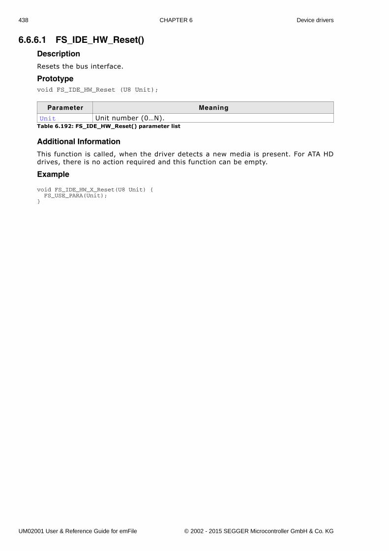
438 CHAPTER 6 Device drivers
6.6.6.1 FS_IDE_HW_Reset()Description
Resets the bus interface.
Prototypevoid FS_IDE_HW_Reset (U8 Unit);
Additional Information
This function is called, when the driver detects a new media is present. For ATA HDdrives, there is no action required and this function can be empty.
Example
void FS_IDE_HW_X_Reset(U8 Unit) { FS_USE_PARA(Unit);}
Parameter Meaning
Unit Unit number (0�N).Table 6.192: FS_IDE_HW_Reset() parameter list
UM02001 User & Reference Guide for emFile © 2002 - 2015 SEGGER Microcontroller GmbH & Co. KG
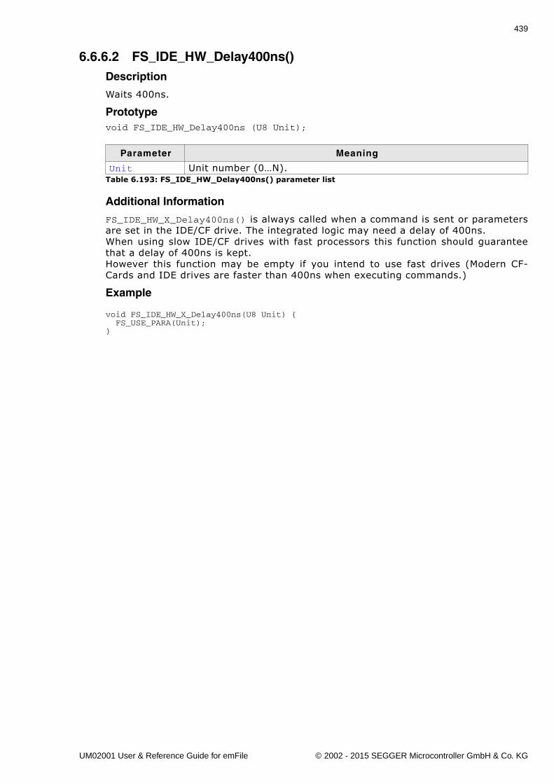
439
6.6.6.2 FS_IDE_HW_Delay400ns()Description
Waits 400ns.
Prototypevoid FS_IDE_HW_Delay400ns (U8 Unit);
Additional Information
FS_IDE_HW_X_Delay400ns() is always called when a command is sent or parametersare set in the IDE/CF drive. The integrated logic may need a delay of 400ns.When using slow IDE/CF drives with fast processors this function should guaranteethat a delay of 400ns is kept.However this function may be empty if you intend to use fast drives (Modern CF-Cards and IDE drives are faster than 400ns when executing commands.)
Example
void FS_IDE_HW_X_Delay400ns(U8 Unit) { FS_USE_PARA(Unit);}
Parameter Meaning
Unit Unit number (0�N).Table 6.193: FS_IDE_HW_Delay400ns() parameter list
UM02001 User & Reference Guide for emFile © 2002 - 2015 SEGGER Microcontroller GmbH & Co. KG
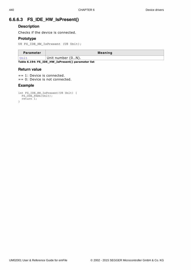
440 CHAPTER 6 Device drivers
6.6.6.3 FS_IDE_HW_IsPresent()Description
Checks if the device is connected.
PrototypeU8 FS_IDE_HW_IsPresent (U8 Unit);
Return value
== 1: Device is connected.== 0: Device is not connected.
Example
int FS_IDE_HW_IsPresent(U8 Unit) { FS_USE_PARA(Unit); return 1;}
Parameter Meaning
Unit Unit number (0�N).Table 6.194: FS_IDE_HW_IsPresent() parameter list
UM02001 User & Reference Guide for emFile © 2002 - 2015 SEGGER Microcontroller GmbH & Co. KG
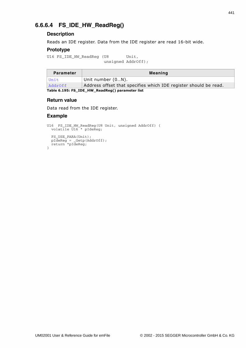
441
6.6.6.4 FS_IDE_HW_ReadReg()Description
Reads an IDE register. Data from the IDE register are read 16-bit wide.
PrototypeU16 FS_IDE_HW_ReadReg (U8 Unit, unsigned AddrOff);
Return value
Data read from the IDE register.
Example
U16 FS_IDE_HW_ReadReg(U8 Unit, unsigned AddrOff) { volatile U16 * pIdeReg; FS_USE_PARA(Unit); pIdeReg = _Getp(AddrOff); return *pIdeReg;}
Parameter Meaning
Unit Unit number (0�N).AddrOff Address offset that specifies which IDE register should be read.
Table 6.195: FS_IDE_HW_ReadReg() parameter list
UM02001 User & Reference Guide for emFile © 2002 - 2015 SEGGER Microcontroller GmbH & Co. KG
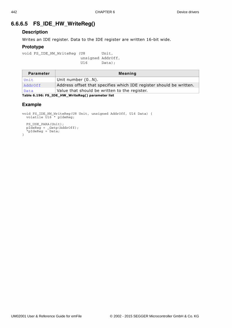
442 CHAPTER 6 Device drivers
6.6.6.5 FS_IDE_HW_WriteReg()Description
Writes an IDE register. Data to the IDE register are written 16-bit wide.
Prototypevoid FS_IDE_HW_WriteReg (U8 Unit, unsigned AddrOff, U16 Data);
Example
void FS_IDE_HW_WriteReg(U8 Unit, unsigned AddrOff, U16 Data) { volatile U16 * pIdeReg; FS_USE_PARA(Unit); pIdeReg = _Getp(AddrOff); *pIdeReg = Data;}
Parameter Meaning
Unit Unit number (0�N).AddrOff Address offset that specifies which IDE register should be written.Data Value that should be written to the register.
Table 6.196: FS_IDE_HW_WriteReg() parameter list
UM02001 User & Reference Guide for emFile © 2002 - 2015 SEGGER Microcontroller GmbH & Co. KG
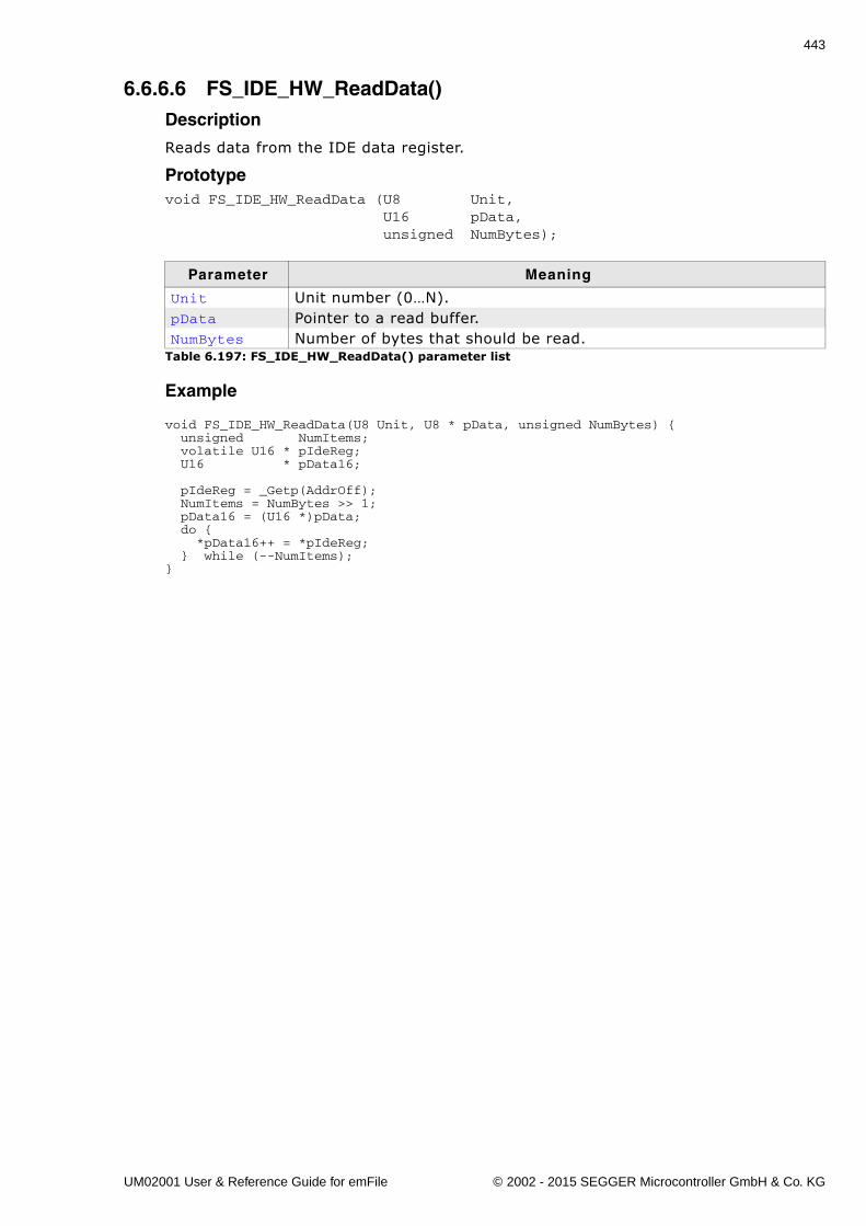
443
6.6.6.6 FS_IDE_HW_ReadData()Description
Reads data from the IDE data register.
Prototypevoid FS_IDE_HW_ReadData (U8 Unit, U16 pData, unsigned NumBytes);
Example
void FS_IDE_HW_ReadData(U8 Unit, U8 * pData, unsigned NumBytes) { unsigned NumItems; volatile U16 * pIdeReg; U16 * pData16;
pIdeReg = _Getp(AddrOff); NumItems = NumBytes >> 1; pData16 = (U16 *)pData; do { *pData16++ = *pIdeReg; } while (--NumItems);}
Parameter Meaning
Unit Unit number (0�N).pData Pointer to a read buffer.NumBytes Number of bytes that should be read.
Table 6.197: FS_IDE_HW_ReadData() parameter list
UM02001 User & Reference Guide for emFile © 2002 - 2015 SEGGER Microcontroller GmbH & Co. KG
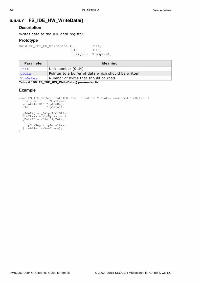
444 CHAPTER 6 Device drivers
6.6.6.7 FS_IDE_HW_WriteData()Description
Writes data to the IDE data register.
Prototypevoid FS_IDE_HW_WriteData (U8 Unit, U16 Data, unsigned NumBytes);
Example
void FS_IDE_HW_WriteData(U8 Unit, const U8 * pData, unsigned NumBytes) { unsigned NumItems; volatile U16 * pIdeReg; U16 * pData16;
pIdeReg = _Getp(AddrOff); NumItems = NumBytes >> 1; pData16 = (U16 *)pData; do { *pIdeReg = *pData16++; } while (--NumItems);}
Parameter Meaning
Unit Unit number (0�N).pData Pointer to a buffer of data which should be written.NumBytes Number of bytes that should be read.
Table 6.198: FS_IDE_HW_WriteData() parameter list
UM02001 User & Reference Guide for emFile © 2002 - 2015 SEGGER Microcontroller GmbH & Co. KG
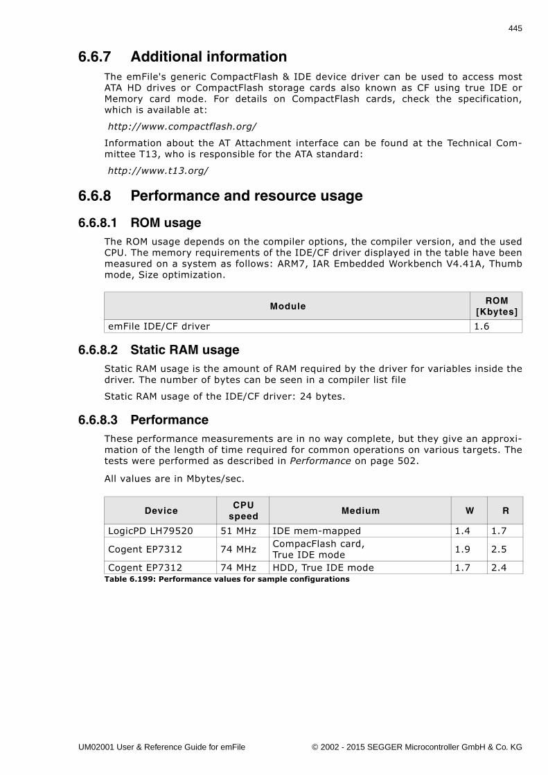
445
6.6.7 Additional informationThe emFile's generic CompactFlash & IDE device driver can be used to access mostATA HD drives or CompactFlash storage cards also known as CF using true IDE orMemory card mode. For details on CompactFlash cards, check the specification,which is available at:
http://www.compactflash.org/
Information about the AT Attachment interface can be found at the Technical Com-mittee T13, who is responsible for the ATA standard:
http://www.t13.org/
6.6.8 Performance and resource usage
6.6.8.1 ROM usageThe ROM usage depends on the compiler options, the compiler version, and the usedCPU. The memory requirements of the IDE/CF driver displayed in the table have beenmeasured on a system as follows: ARM7, IAR Embedded Workbench V4.41A, Thumbmode, Size optimization.
6.6.8.2 Static RAM usageStatic RAM usage is the amount of RAM required by the driver for variables inside thedriver. The number of bytes can be seen in a compiler list file
Static RAM usage of the IDE/CF driver: 24 bytes.
6.6.8.3 PerformanceThese performance measurements are in no way complete, but they give an approxi-mation of the length of time required for common operations on various targets. Thetests were performed as described in Performance on page 502.
All values are in Mbytes/sec.
ModuleROM
[Kbytes]
emFile IDE/CF driver 1.6
DeviceCPU
speedMedium W R
LogicPD LH79520 51 MHz IDE mem-mapped 1.4 1.7
Cogent EP7312 74 MHz CompacFlash card,True IDE mode 1.9 2.5
Cogent EP7312 74 MHz HDD, True IDE mode 1.7 2.4Table 6.199: Performance values for sample configurations
UM02001 User & Reference Guide for emFile © 2002 - 2015 SEGGER Microcontroller GmbH & Co. KG
446 CHAPTER 6 Device drivers
6.7 WinDrive driverThe purpose of this driver is to run emFile for test and simulation purposes on a PCrunning Windows. Refer to the chapter Getting started on page 27 for a sample usingthe WinDrive driver.
6.7.1 Supported hardwareThis driver is compatible with use any Windows logical driver on a Windows NT sys-tem.
Be aware, that Win9X is not supported, because it cannot access logicaldrives with �CreateFile�.
6.7.2 Theory of operationemFile supports in this version FAT and EFS file systems only. NTFS logical drivescannot be accessed by emFile. It can be used either to store/access files on a floppydisk or using an USB-Card reader for accessing flash cards. It works also on FAT for-matted hard disks or partitions.
Note: Do not use this driver on partitions containing important data. It is prima-rily meant to be used for evaluation purposes. Problems may occur if the programusing emFile is debugged or terminated using the task manager.
6.7.3 Fail-safe operationAlthough not important since the driver is not designed to be used in an embeddeddevice, the data is normally safe. Data safety is handled by the underlying operatingsystem and hardware.
6.7.4 Wear levelingThe driver does not need wear leveling.
6.7.5 Configuring the driver
6.7.5.1 Adding the driver to emFileTo add the driver use FS_AddDevice() with the driver label FS_WINDRIVE_Driver.This function has to be called from within FS_X_AddDevices(). Refer toFS_X_AddDevices() on page 472 for more information.
Example
FS_AddDevice(&FS_WINDRIVE_Driver);
6.7.5.2 WINDRIVE_Configure()Description
Configures a windows drive instance. This function has to be called from withinFS_X_AddDevices() after adding an instance of the Windrive driver. Refer toFS_X_AddDevices() on page 472 for more information.
UM02001 User & Reference Guide for emFile © 2002 - 2015 SEGGER Microcontroller GmbH & Co. KG
447
Prototypevoid WINDRIVE_Configure(U8 Unit, const char * sDriveName);
Additional information
If sDriveName is NULL a configuration dialog will be opened to select which driveshould be used.
6.7.6 Hardware functionsThe WinDrive driver does not need any hardware functions.
6.7.7 Additional informationNone.
Parameter Description
Unit Unit number (0�n).
sDriveNamePointer to string which contains the windows drive name. For example:"\\\\.\\a:"
Table 6.200: FS_Windrive_Configure() parameter list
UM02001 User & Reference Guide for emFile © 2002 - 2015 SEGGER Microcontroller GmbH & Co. KG
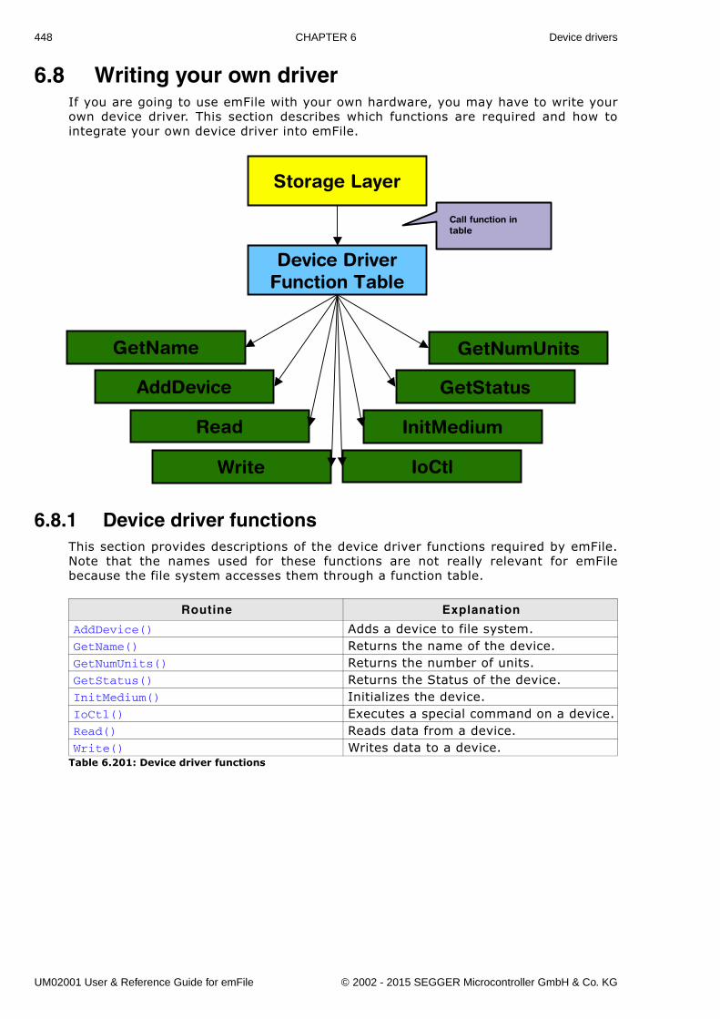
448 CHAPTER 6 Device drivers
6.8 Writing your own driverIf you are going to use emFile with your own hardware, you may have to write yourown device driver. This section describes which functions are required and how tointegrate your own device driver into emFile.
6.8.1 Device driver functionsThis section provides descriptions of the device driver functions required by emFile.Note that the names used for these functions are not really relevant for emFilebecause the file system accesses them through a function table.
Routine Explanation
AddDevice() Adds a device to file system.GetName() Returns the name of the device.GetNumUnits() Returns the number of units.GetStatus() Returns the Status of the device.InitMedium() Initializes the device.IoCtl() Executes a special command on a device.Read() Reads data from a device.Write() Writes data to a device.
Table 6.201: Device driver functions
Storage Layer
Device DriverFunction Table
GetName
Call function in table
Read
AddDevice GetStatus
GetNumUnits
InitMedium
IoCtlWrite
UM02001 User & Reference Guide for emFile © 2002 - 2015 SEGGER Microcontroller GmbH & Co. KG
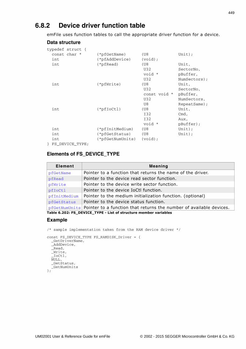
449
6.8.2 Device driver function tableemFile uses function tables to call the appropriate driver function for a device.
Data structuretypedef struct { const char * (*pfGetName) (U8 Unit); int (*pfAddDevice) (void); int (*pfRead) (U8 Unit, U32 SectorNo, void * pBuffer, U32 NumSectors); int (*pfWrite) (U8 Unit, U32 SectorNo, const void * pBuffer, U32 NumSectors, U8 RepeatSame); int (*pfIoCtl) (U8 Unit, I32 Cmd, I32 Aux, void * pBuffer); int (*pfInitMedium) (U8 Unit); int (*pfGetStatus) (U8 Unit); int (*pfGetNumUnits) (void);} FS_DEVICE_TYPE;
Elements of FS_DEVICE_TYPE
Example
/* sample implementation taken from the RAM device driver */
const FS_DEVICE_TYPE FS_RAMDISK_Driver = { _GetDriverName, _AddDevice, _Read, _Write, _IoCtl, NULL, _GetStatus, _GetNumUnits};
Element Meaning
pfGetName Pointer to a function that returns the name of the driver.pfRead Pointer to the device read sector function.pfWrite Pointer to the device write sector function.pfIoCtl Pointer to the device IoCtl function.pfInitMedium Pointer to the medium initialization function. (optional)pfGetStatus Pointer to the device status function.pfGetNumUnits Pointer to a function that returns the number of available devices.
Table 6.202: FS_DEVICE_TYPE - List of structure member variables
UM02001 User & Reference Guide for emFile © 2002 - 2015 SEGGER Microcontroller GmbH & Co. KG
450 CHAPTER 6 Device drivers
6.8.3 Integrating a new driverThere is an empty skeleton driver called generic in the Sample\Driver\DriverTem-plate\ folder. This driver can be easily modified to get any block oriented storagedevice working with the file system.
To add the driver to emFile, FS_AddDevice() should be called from withinFS_X_AddDevices() to mount the device driver to emFile before accessing the deviceor its units. Refer to FS_X_AddDevices() on page 472 for more information.
UM02001 User & Reference Guide for emFile © 2002 - 2015 SEGGER Microcontroller GmbH & Co. KG
451
Chapter 7
Logical drivers
Optional software components located between file system layer and device driverlayer which extend the functionality of emFile.
UM02001 User & Reference Guide for emFile © 2002 - 2015 SEGGER Microcontroller GmbH & Co. KG
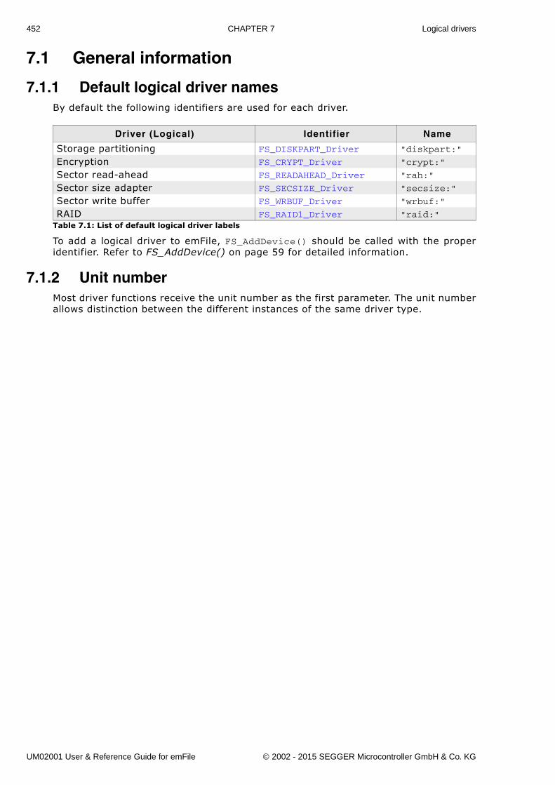
452 CHAPTER 7 Logical drivers
7.1 General information
7.1.1 Default logical driver namesBy default the following identifiers are used for each driver.
To add a logical driver to emFile, FS_AddDevice() should be called with the properidentifier. Refer to FS_AddDevice() on page 59 for detailed information.
7.1.2 Unit numberMost driver functions receive the unit number as the first parameter. The unit numberallows distinction between the different instances of the same driver type.
Driver (Logical) Identifier Name
Storage partitioning FS_DISKPART_Driver "diskpart:"
Encryption FS_CRYPT_Driver "crypt:"
Sector read-ahead FS_READAHEAD_Driver "rah:"
Sector size adapter FS_SECSIZE_Driver "secsize:"
Sector write buffer FS_WRBUF_Driver "wrbuf:"
RAID FS_RAID1_Driver "raid:"Table 7.1: List of default logical driver labels
UM02001 User & Reference Guide for emFile © 2002 - 2015 SEGGER Microcontroller GmbH & Co. KG
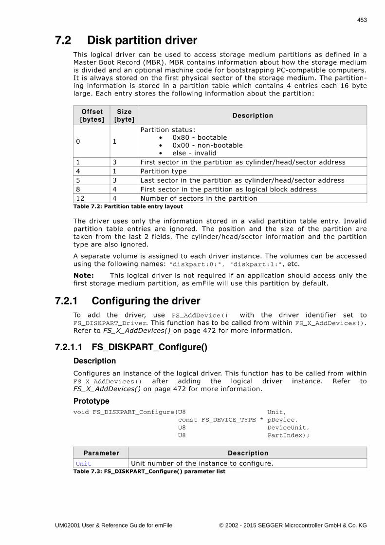
453
7.2 Disk partition driverThis logical driver can be used to access storage medium partitions as defined in aMaster Boot Record (MBR). MBR contains information about how the storage mediumis divided and an optional machine code for bootstrapping PC-compatible computers.It is always stored on the first physical sector of the storage medium. The partition-ing information is stored in a partition table which contains 4 entries each 16 bytelarge. Each entry stores the following information about the partition:
The driver uses only the information stored in a valid partition table entry. Invalidpartition table entries are ignored. The position and the size of the partition aretaken from the last 2 fields. The cylinder/head/sector information and the partitiontype are also ignored.
A separate volume is assigned to each driver instance. The volumes can be accessedusing the following names: "diskpart:0:", "diskpart:1:", etc.
Note: This logical driver is not required if an application should access only thefirst storage medium partition, as emFile will use this partition by default.
7.2.1 Configuring the driverTo add the driver, use FS_AddDevice() with the driver identifier set toFS_DISKPART_Driver. This function has to be called from within FS_X_AddDevices().Refer to FS_X_AddDevices() on page 472 for more information.
7.2.1.1 FS_DISKPART_Configure()Description
Configures an instance of the logical driver. This function has to be called from withinFS_X_AddDevices() after adding the logical driver instance. Refer toFS_X_AddDevices() on page 472 for more information.
Prototypevoid FS_DISKPART_Configure(U8 Unit, const FS_DEVICE_TYPE * pDevice, U8 DeviceUnit, U8 PartIndex);
Offset[bytes]
Size[byte]
Description
0 1
Partition status:� 0x80 - bootable� 0x00 - non-bootable� else - invalid
1 3 First sector in the partition as cylinder/head/sector address4 1 Partition type5 3 Last sector in the partition as cylinder/head/sector address8 4 First sector in the partition as logical block address12 4 Number of sectors in the partition
Table 7.2: Partition table entry layout
Parameter Description
Unit Unit number of the instance to configure.Table 7.3: FS_DISKPART_Configure() parameter list
UM02001 User & Reference Guide for emFile © 2002 - 2015 SEGGER Microcontroller GmbH & Co. KG
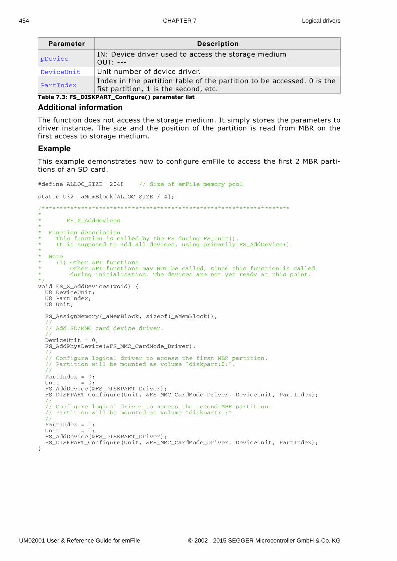
454 CHAPTER 7 Logical drivers
Additional information
The function does not access the storage medium. It simply stores the parameters todriver instance. The size and the position of the partition is read from MBR on thefirst access to storage medium.
Example
This example demonstrates how to configure emFile to access the first 2 MBR parti-tions of an SD card.
#define ALLOC_SIZE 2048 // Size of emFile memory pool
static U32 _aMemBlock[ALLOC_SIZE / 4];
/*********************************************************************** FS_X_AddDevices** Function description* This function is called by the FS during FS_Init().* It is supposed to add all devices, using primarily FS_AddDevice().* * Note* (1) Other API functions* Other API functions may NOT be called, since this function is called* during initialisation. The devices are not yet ready at this point.*/void FS_X_AddDevices(void) { U8 DeviceUnit; U8 PartIndex; U8 Unit;
FS_AssignMemory(_aMemBlock, sizeof(_aMemBlock)); // // Add SD/MMC card device driver. // DeviceUnit = 0; FS_AddPhysDevice(&FS_MMC_CardMode_Driver); // // Configure logical driver to access the first MBR partition. // Partition will be mounted as volume “diskpart:0:“. // PartIndex = 0; Unit = 0; FS_AddDevice(&FS_DISKPART_Driver); FS_DISKPART_Configure(Unit, &FS_MMC_CardMode_Driver, DeviceUnit, PartIndex); // // Configure logical driver to access the second MBR partition. // Partition will be mounted as volume “diskpart:1:“. // PartIndex = 1; Unit = 1; FS_AddDevice(&FS_DISKPART_Driver); FS_DISKPART_Configure(Unit, &FS_MMC_CardMode_Driver, DeviceUnit, PartIndex);}
pDeviceIN: Device driver used to access the storage mediumOUT: ---
DeviceUnit Unit number of device driver.
PartIndexIndex in the partition table of the partition to be accessed. 0 is the fist partition, 1 is the second, etc.
Parameter Description
Table 7.3: FS_DISKPART_Configure() parameter list
UM02001 User & Reference Guide for emFile © 2002 - 2015 SEGGER Microcontroller GmbH & Co. KG
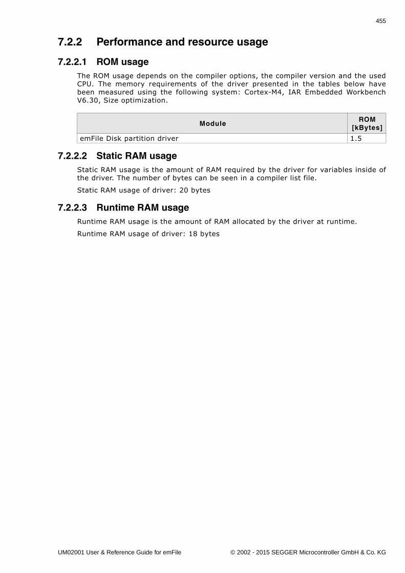
455
7.2.2 Performance and resource usage
7.2.2.1 ROM usageThe ROM usage depends on the compiler options, the compiler version and the usedCPU. The memory requirements of the driver presented in the tables below havebeen measured using the following system: Cortex-M4, IAR Embedded WorkbenchV6.30, Size optimization.
7.2.2.2 Static RAM usageStatic RAM usage is the amount of RAM required by the driver for variables inside ofthe driver. The number of bytes can be seen in a compiler list file.
Static RAM usage of driver: 20 bytes
7.2.2.3 Runtime RAM usageRuntime RAM usage is the amount of RAM allocated by the driver at runtime.
Runtime RAM usage of driver: 18 bytes
ModuleROM
[kBytes]
emFile Disk partition driver 1.5
UM02001 User & Reference Guide for emFile © 2002 - 2015 SEGGER Microcontroller GmbH & Co. KG
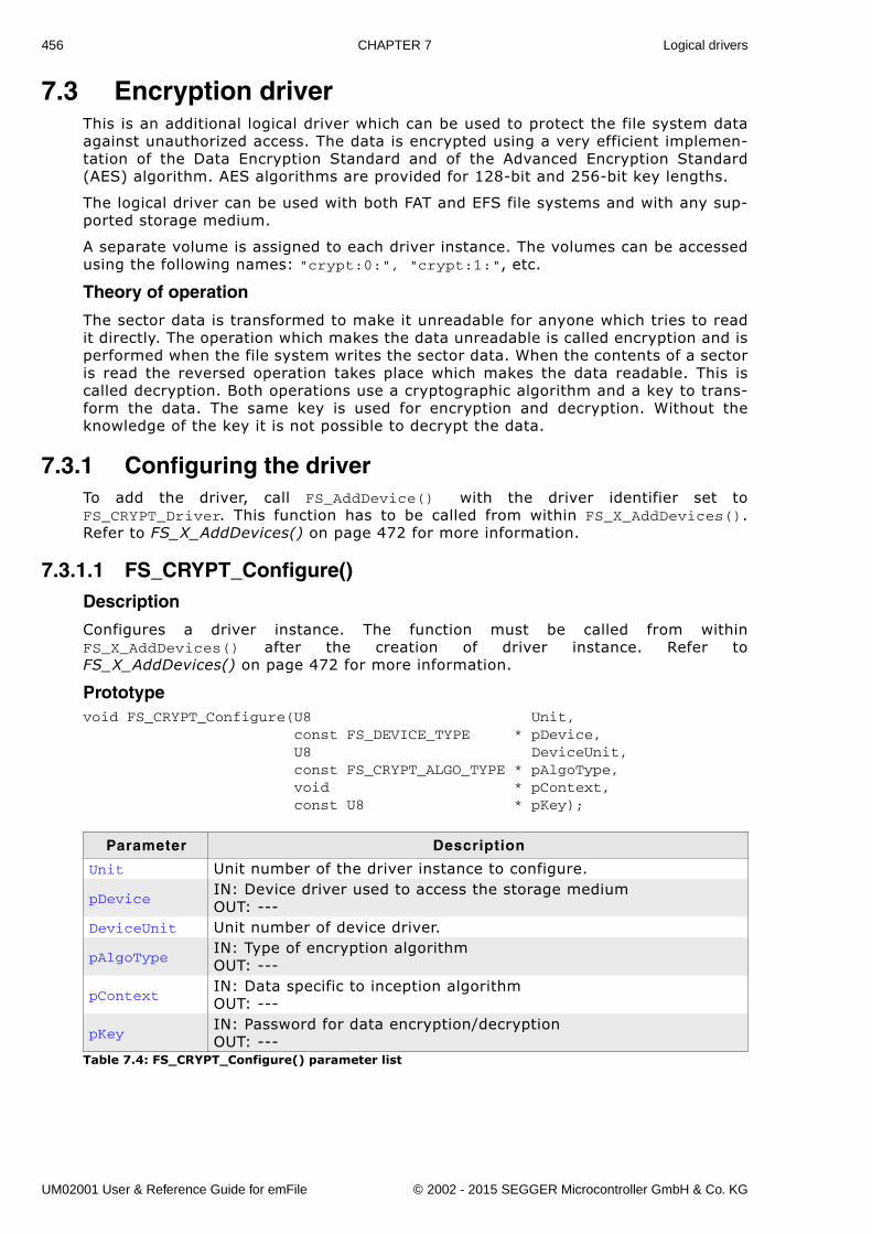
456 CHAPTER 7 Logical drivers
7.3 Encryption driverThis is an additional logical driver which can be used to protect the file system dataagainst unauthorized access. The data is encrypted using a very efficient implemen-tation of the Data Encryption Standard and of the Advanced Encryption Standard(AES) algorithm. AES algorithms are provided for 128-bit and 256-bit key lengths.
The logical driver can be used with both FAT and EFS file systems and with any sup-ported storage medium.
A separate volume is assigned to each driver instance. The volumes can be accessedusing the following names: "crypt:0:", "crypt:1:", etc.
Theory of operation
The sector data is transformed to make it unreadable for anyone which tries to readit directly. The operation which makes the data unreadable is called encryption and isperformed when the file system writes the sector data. When the contents of a sectoris read the reversed operation takes place which makes the data readable. This iscalled decryption. Both operations use a cryptographic algorithm and a key to trans-form the data. The same key is used for encryption and decryption. Without theknowledge of the key it is not possible to decrypt the data.
7.3.1 Configuring the driverTo add the driver, call FS_AddDevice() with the driver identifier set toFS_CRYPT_Driver. This function has to be called from within FS_X_AddDevices().Refer to FS_X_AddDevices() on page 472 for more information.
7.3.1.1 FS_CRYPT_Configure()Description
Configures a driver instance. The function must be called from withinFS_X_AddDevices() after the creation of driver instance. Refer toFS_X_AddDevices() on page 472 for more information.
Prototypevoid FS_CRYPT_Configure(U8 Unit, const FS_DEVICE_TYPE * pDevice, U8 DeviceUnit, const FS_CRYPT_ALGO_TYPE * pAlgoType, void * pContext, const U8 * pKey);
Parameter Description
Unit Unit number of the driver instance to configure.
pDeviceIN: Device driver used to access the storage mediumOUT: ---
DeviceUnit Unit number of device driver.
pAlgoTypeIN: Type of encryption algorithmOUT: ---
pContextIN: Data specific to inception algorithmOUT: ---
pKeyIN: Password for data encryption/decryptionOUT: ---
Table 7.4: FS_CRYPT_Configure() parameter list
UM02001 User & Reference Guide for emFile © 2002 - 2015 SEGGER Microcontroller GmbH & Co. KG
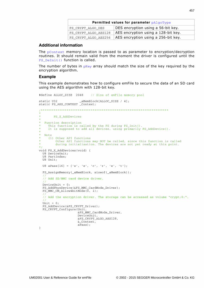
457
Additional information
The pContext memory location is passed to as parameter to encryption/decryptionroutines. It should remain valid from the moment the driver is configured until theFS_DeInit() function is called.
The number of bytes in pKey array should match the size of the key required by theencryption algorithm.
Example
This example demonstrates how to configure emFile to secure the data of an SD cardusing the AES algorithm with 128-bit key.
#define ALLOC_SIZE 2048 // Size of emFile memory pool
static U32 _aMemBlock[ALLOC_SIZE / 4];static FS_AES_CONTEXT _Context;
/*********************************************************************** FS_X_AddDevices** Function description* This function is called by the FS during FS_Init().* It is supposed to add all devices, using primarily FS_AddDevice().* * Note* (1) Other API functions* Other API functions may NOT be called, since this function is called* during initialisation. The devices are not yet ready at this point.*/void FS_X_AddDevices(void) { U8 DeviceUnit; U8 PartIndex; U8 Unit;
U8 aPass[16] = {'s', 'e', 'c', 'r', 'e', 't'};
FS_AssignMemory(_aMemBlock, sizeof(_aMemBlock)); // // Add SD/MMC card device driver. // DeviceUnit = 0; FS_AddPhysDevice(&FS_MMC_CardMode_Driver); FS_MMC_CM_Allow4bitMode(0, 1); // // Add the encryption driver. The storage can be accessed as volume “crypt:0:“. // Unit = 0; FS_AddDevice(&FS_CRYPT_Driver); FS_CRYPT_Configure(Unit, &FS_MMC_CardMode_Driver, DeviceUnit, &FS_CRYPT_ALGO_AES128, &_Context, aPass);}
Permitted values for parameter pAlgoType
FS_CRYPT_ALGO_DES DES encryption using a 56-bit key.FS_CRYPT_ALGO_AES128 AES encryption using a 128-bit key.FS_CRYPT_ALGO_AES256 AES encryption using a 256-bit key.
UM02001 User & Reference Guide for emFile © 2002 - 2015 SEGGER Microcontroller GmbH & Co. KG
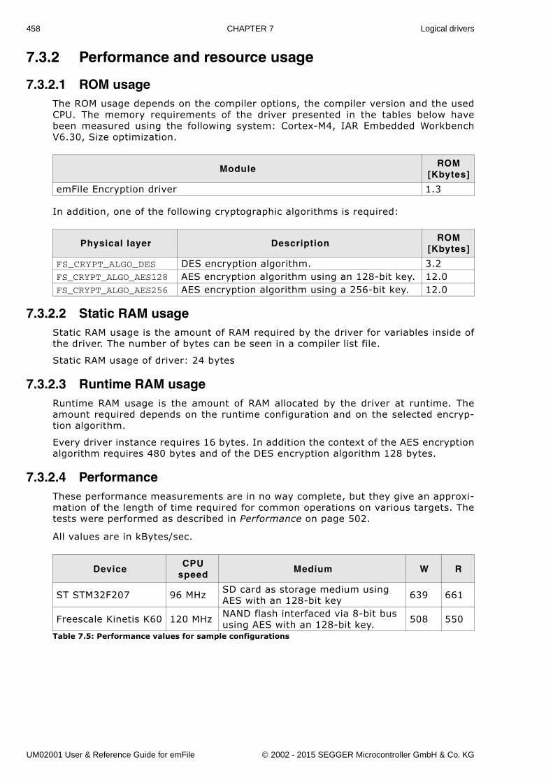
458 CHAPTER 7 Logical drivers
7.3.2 Performance and resource usage
7.3.2.1 ROM usageThe ROM usage depends on the compiler options, the compiler version and the usedCPU. The memory requirements of the driver presented in the tables below havebeen measured using the following system: Cortex-M4, IAR Embedded WorkbenchV6.30, Size optimization.
In addition, one of the following cryptographic algorithms is required:
7.3.2.2 Static RAM usageStatic RAM usage is the amount of RAM required by the driver for variables inside ofthe driver. The number of bytes can be seen in a compiler list file.
Static RAM usage of driver: 24 bytes
7.3.2.3 Runtime RAM usageRuntime RAM usage is the amount of RAM allocated by the driver at runtime. Theamount required depends on the runtime configuration and on the selected encryp-tion algorithm.
Every driver instance requires 16 bytes. In addition the context of the AES encryptionalgorithm requires 480 bytes and of the DES encryption algorithm 128 bytes.
7.3.2.4 PerformanceThese performance measurements are in no way complete, but they give an approxi-mation of the length of time required for common operations on various targets. Thetests were performed as described in Performance on page 502.
All values are in kBytes/sec.
ModuleROM
[Kbytes]
emFile Encryption driver 1.3
Physical layer DescriptionROM
[Kbytes]
FS_CRYPT_ALGO_DES DES encryption algorithm. 3.2FS_CRYPT_ALGO_AES128 AES encryption algorithm using an 128-bit key. 12.0FS_CRYPT_ALGO_AES256 AES encryption algorithm using a 256-bit key. 12.0
DeviceCPU
speedMedium W R
ST STM32F207 96 MHz SD card as storage medium using AES with an 128-bit key 639 661
Freescale Kinetis K60 120 MHz NAND flash interfaced via 8-bit bus using AES with an 128-bit key. 508 550
Table 7.5: Performance values for sample configurations
UM02001 User & Reference Guide for emFile © 2002 - 2015 SEGGER Microcontroller GmbH & Co. KG
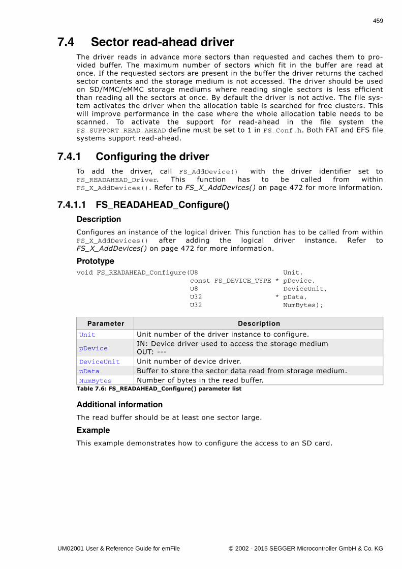
459
7.4 Sector read-ahead driverThe driver reads in advance more sectors than requested and caches them to pro-vided buffer. The maximum number of sectors which fit in the buffer are read atonce. If the requested sectors are present in the buffer the driver returns the cachedsector contents and the storage medium is not accessed. The driver should be usedon SD/MMC/eMMC storage mediums where reading single sectors is less efficientthan reading all the sectors at once. By default the driver is not active. The file sys-tem activates the driver when the allocation table is searched for free clusters. Thiswill improve performance in the case where the whole allocation table needs to bescanned. To activate the support for read-ahead in the file system theFS_SUPPORT_READ_AHEAD define must be set to 1 in FS_Conf.h. Both FAT and EFS filesystems support read-ahead.
7.4.1 Configuring the driverTo add the driver, call FS_AddDevice() with the driver identifier set toFS_READAHEAD_Driver. This function has to be called from withinFS_X_AddDevices(). Refer to FS_X_AddDevices() on page 472 for more information.
7.4.1.1 FS_READAHEAD_Configure()Description
Configures an instance of the logical driver. This function has to be called from withinFS_X_AddDevices() after adding the logical driver instance. Refer toFS_X_AddDevices() on page 472 for more information.
Prototypevoid FS_READAHEAD_Configure(U8 Unit, const FS_DEVICE_TYPE * pDevice, U8 DeviceUnit, U32 * pData, U32 NumBytes);
Additional information
The read buffer should be at least one sector large.
Example
This example demonstrates how to configure the access to an SD card.
Parameter Description
Unit Unit number of the driver instance to configure.
pDeviceIN: Device driver used to access the storage mediumOUT: ---
DeviceUnit Unit number of device driver.pData Buffer to store the sector data read from storage medium.NumBytes Number of bytes in the read buffer.
Table 7.6: FS_READAHEAD_Configure() parameter list
UM02001 User & Reference Guide for emFile © 2002 - 2015 SEGGER Microcontroller GmbH & Co. KG
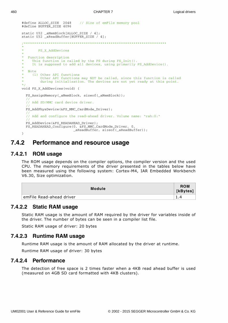
460 CHAPTER 7 Logical drivers
#define ALLOC_SIZE 2048 // Size of emFile memory pool#define BUFFER_SIZE 4096
static U32 _aMemBlock[ALLOC_SIZE / 4];static U32 _aReadBuffer[BUFFER_SIZE / 4];
/*********************************************************************** FS_X_AddDevices** Function description* This function is called by the FS during FS_Init().* It is supposed to add all devices, using primarily FS_AddDevice().* * Note* (1) Other API functions* Other API functions may NOT be called, since this function is called* during initialisation. The devices are not yet ready at this point.*/void FS_X_AddDevices(void) {
FS_AssignMemory(_aMemBlock, sizeof(_aMemBlock)); // // Add SD/MMC card device driver. // FS_AddPhysDevice(&FS_MMC_CardMode_Driver); // // Add and configure the read-ahead driver. Volume name: “rah:0:“ // FS_AddDevice(&FS_READAHEAD_Driver); FS_READAHEAD_Configure(0, &FS_MMC_CardMode_Driver, 0, _aReadBuffer, sizeof(_aReadBuffer));}
7.4.2 Performance and resource usage
7.4.2.1 ROM usageThe ROM usage depends on the compiler options, the compiler version and the usedCPU. The memory requirements of the driver presented in the tables below havebeen measured using the following system: Cortex-M4, IAR Embedded WorkbenchV6.30, Size optimization.
7.4.2.2 Static RAM usageStatic RAM usage is the amount of RAM required by the driver for variables inside ofthe driver. The number of bytes can be seen in a compiler list file.
Static RAM usage of driver: 20 bytes
7.4.2.3 Runtime RAM usageRuntime RAM usage is the amount of RAM allocated by the driver at runtime.
Runtime RAM usage of driver: 30 bytes
7.4.2.4 PerformanceThe detection of free space is 2 times faster when a 4KB read ahead buffer is used(measured on 4GB SD card formatted with 4KB clusters).
ModuleROM
[kBytes]
emFile Read-ahead driver 1.4
UM02001 User & Reference Guide for emFile © 2002 - 2015 SEGGER Microcontroller GmbH & Co. KG
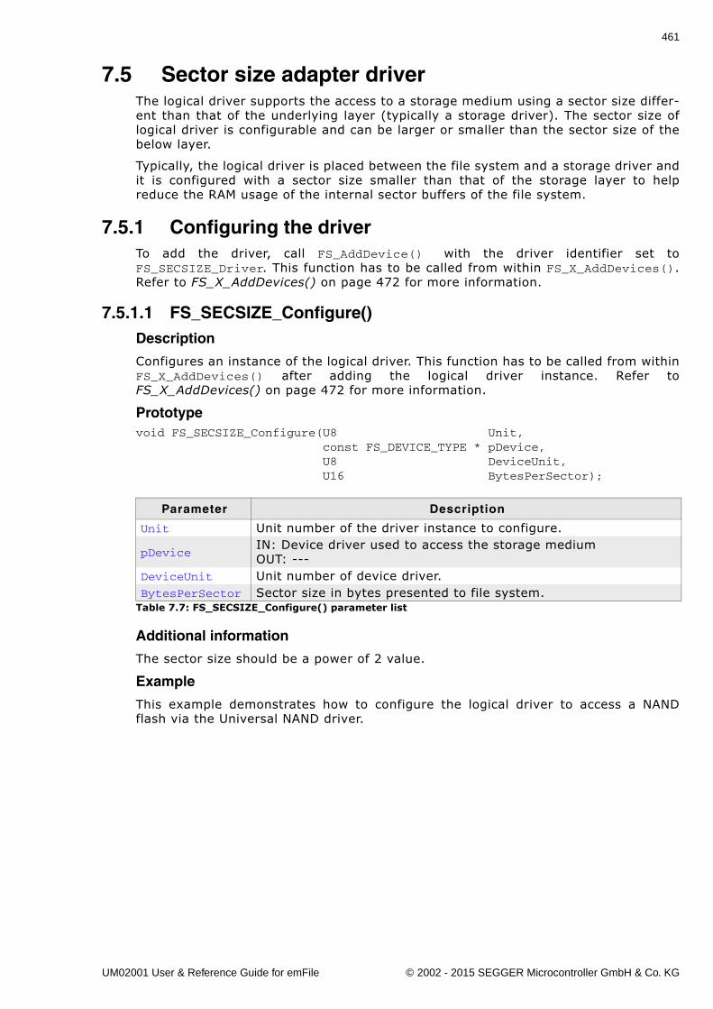
461
7.5 Sector size adapter driverThe logical driver supports the access to a storage medium using a sector size differ-ent than that of the underlying layer (typically a storage driver). The sector size oflogical driver is configurable and can be larger or smaller than the sector size of thebelow layer.
Typically, the logical driver is placed between the file system and a storage driver andit is configured with a sector size smaller than that of the storage layer to helpreduce the RAM usage of the internal sector buffers of the file system.
7.5.1 Configuring the driverTo add the driver, call FS_AddDevice() with the driver identifier set toFS_SECSIZE_Driver. This function has to be called from within FS_X_AddDevices().Refer to FS_X_AddDevices() on page 472 for more information.
7.5.1.1 FS_SECSIZE_Configure()Description
Configures an instance of the logical driver. This function has to be called from withinFS_X_AddDevices() after adding the logical driver instance. Refer toFS_X_AddDevices() on page 472 for more information.
Prototypevoid FS_SECSIZE_Configure(U8 Unit, const FS_DEVICE_TYPE * pDevice, U8 DeviceUnit, U16 BytesPerSector);
Additional information
The sector size should be a power of 2 value.
Example
This example demonstrates how to configure the logical driver to access a NANDflash via the Universal NAND driver.
Parameter Description
Unit Unit number of the driver instance to configure.
pDeviceIN: Device driver used to access the storage mediumOUT: ---
DeviceUnit Unit number of device driver.BytesPerSector Sector size in bytes presented to file system.
Table 7.7: FS_SECSIZE_Configure() parameter list
UM02001 User & Reference Guide for emFile © 2002 - 2015 SEGGER Microcontroller GmbH & Co. KG
462 CHAPTER 7 Logical drivers
#define ALLOC_SIZE 0x8000 // Size of emFile memory pool
static U32 _aMemBlock[ALLOC_SIZE / 4];
/*********************************************************************** FS_X_AddDevices** Function description* This function is called by the FS during FS_Init().* It is supposed to add all devices, using primarily FS_AddDevice().* * Note* (1) Other API functions* Other API functions may NOT be called, since this function is called* during initialisation. The devices are not yet ready at this point.*/void FS_X_AddDevices(void) {
FS_AssignMemory(_aMemBlock, sizeof(_aMemBlock)); // // Add NAND flash device driver. // FS_AddPhysDevice(&FS_NAND_UNI_Driver); FS_NAND_UNI_SetPhyType(0, &FS_NAND_PHY_ONFI); FS_NAND_UNI_SetECCHook(0, &FS_NAND_ECC_HW_NULL); // // Add sector conversion logical driver. // FS_AddDevice(&FS_SECSIZE_Driver); FS_SECSIZE_Configure(0, &FS_NAND_UNI_Driver, 0, 512);}
7.5.2 Performance and resource usage
7.5.2.1 ROM usageThe ROM usage depends on the compiler options, the compiler version and the usedCPU. The memory requirements of the driver presented in the tables below havebeen measured using the following system: Cortex-M4, IAR Embedded WorkbenchV6.30, Size optimization.
7.5.2.2 Static RAM usageStatic RAM usage is the amount of RAM required by the driver for variables inside ofthe driver. The number of bytes can be seen in a compiler list file.
Static RAM usage of driver: 20 bytes
7.5.2.3 Runtime RAM usageRuntime RAM usage is the amount of RAM allocated by the driver at runtime.
Runtime RAM usage of driver: 30 bytes + sector size of storage driver if it is largerthan the sector size configured for the logical driver.
ModuleROM
[kBytes]
emFile Sector size driver 1.1
UM02001 User & Reference Guide for emFile © 2002 - 2015 SEGGER Microcontroller GmbH & Co. KG
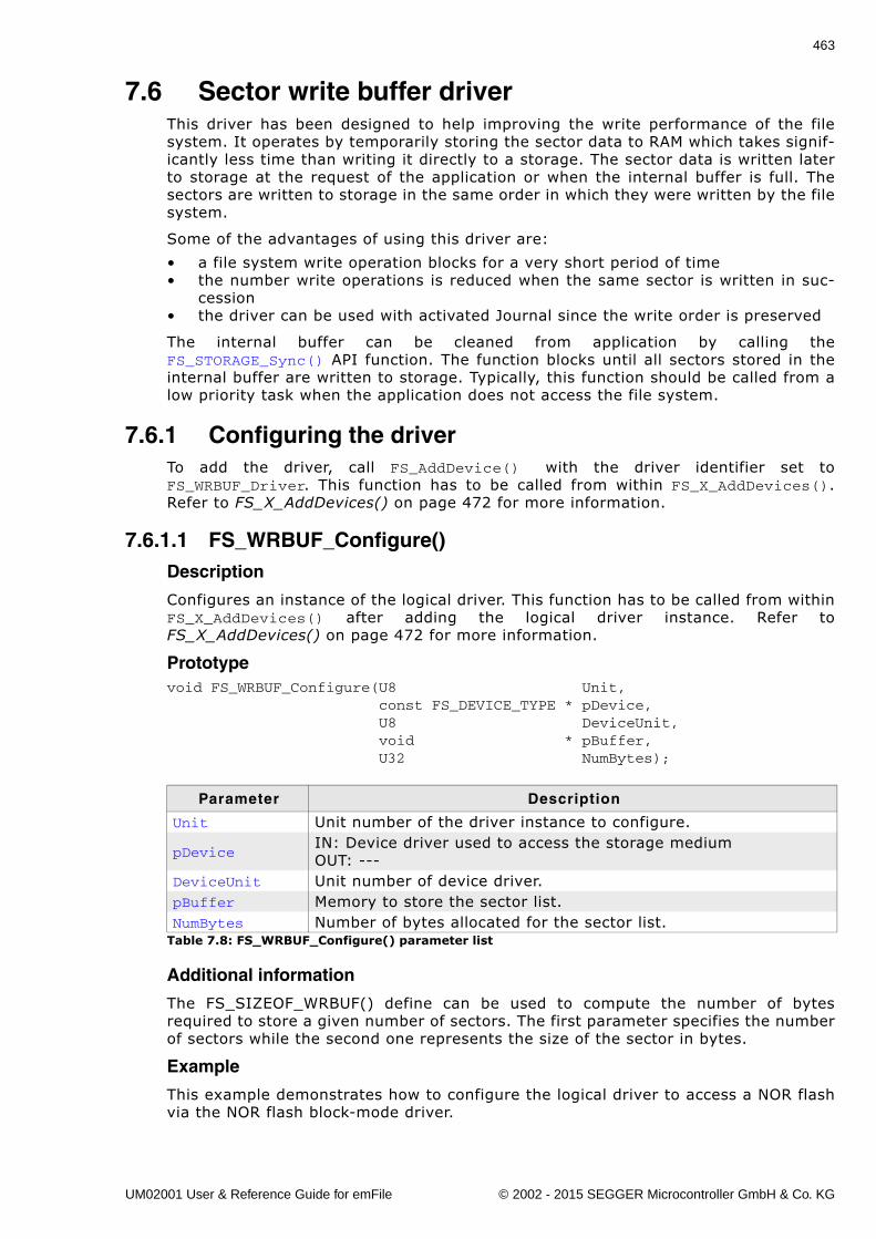
463
7.6 Sector write buffer driverThis driver has been designed to help improving the write performance of the filesystem. It operates by temporarily storing the sector data to RAM which takes signif-icantly less time than writing it directly to a storage. The sector data is written laterto storage at the request of the application or when the internal buffer is full. Thesectors are written to storage in the same order in which they were written by the filesystem.
Some of the advantages of using this driver are:
� a file system write operation blocks for a very short period of time� the number write operations is reduced when the same sector is written in suc-
cession� the driver can be used with activated Journal since the write order is preserved
The internal buffer can be cleaned from application by calling theFS_STORAGE_Sync() API function. The function blocks until all sectors stored in theinternal buffer are written to storage. Typically, this function should be called from alow priority task when the application does not access the file system.
7.6.1 Configuring the driverTo add the driver, call FS_AddDevice() with the driver identifier set toFS_WRBUF_Driver. This function has to be called from within FS_X_AddDevices().Refer to FS_X_AddDevices() on page 472 for more information.
7.6.1.1 FS_WRBUF_Configure()Description
Configures an instance of the logical driver. This function has to be called from withinFS_X_AddDevices() after adding the logical driver instance. Refer toFS_X_AddDevices() on page 472 for more information.
Prototypevoid FS_WRBUF_Configure(U8 Unit, const FS_DEVICE_TYPE * pDevice, U8 DeviceUnit, void * pBuffer, U32 NumBytes);
Additional information
The FS_SIZEOF_WRBUF() define can be used to compute the number of bytesrequired to store a given number of sectors. The first parameter specifies the numberof sectors while the second one represents the size of the sector in bytes.
Example
This example demonstrates how to configure the logical driver to access a NOR flashvia the NOR flash block-mode driver.
Parameter Description
Unit Unit number of the driver instance to configure.
pDeviceIN: Device driver used to access the storage mediumOUT: ---
DeviceUnit Unit number of device driver.pBuffer Memory to store the sector list.NumBytes Number of bytes allocated for the sector list.
Table 7.8: FS_WRBUF_Configure() parameter list
UM02001 User & Reference Guide for emFile © 2002 - 2015 SEGGER Microcontroller GmbH & Co. KG
464 CHAPTER 7 Logical drivers
#define ALLOC_SIZE 0x1000 // Size of emFile memory pool
static U32 _aMemBlock[ALLOC_SIZE / 4];static U32 _aWriteBuffer[FS_SIZEOF_WRBUF(8, 512) / 4];
/*********************************************************************** FS_X_AddDevices** Function description* This function is called by the FS during FS_Init().* It is supposed to add all devices, using primarily FS_AddDevice().* * Note* (1) Other API functions* Other API functions may NOT be called, since this function is called* during initialisation. The devices are not yet ready at this point.*/void FS_X_AddDevices(void) {
FS_AssignMemory(_aMemBlock, sizeof(_aMemBlock)); // // Add and configure the NOR flash driver. // FS_AddPhysDevice(&FS_NOR_BM_Driver); FS_NOR_BM_SetPhyType(0, &FS_NOR_PHY_ST_M25); FS_NOR_BM_Configure(0, 0, 0, 0x100000uL); // // Add and configure the write buffer driver. // FS_AddDevice(&FS_WRBUF_Driver); FS_WRBUF_Configure(0, &FS_MMC_CardMode_Driver, 0, _aWriteBuffer, sizeof(_aWriteBuffer));}
7.6.2 Performance and resource usage
7.6.2.1 ROM usageThe ROM usage depends on the compiler options, the compiler version and the usedCPU. The memory requirements of the driver presented in the tables below havebeen measured using the following system: Cortex-M4, IAR Embedded WorkbenchV6.30, Size optimization.
7.6.2.2 Static RAM usageStatic RAM usage is the amount of RAM required by the driver for variables inside ofthe driver. The number of bytes can be seen in a compiler list file.
Static RAM usage of driver: 20 bytes
7.6.2.3 Runtime RAM usageRuntime RAM usage is the amount of RAM allocated by the driver at runtime.
Runtime RAM usage of driver: 32 bytes.
ModuleROM
[kBytes]
emFile Sector write buffer driver 1.2
UM02001 User & Reference Guide for emFile © 2002 - 2015 SEGGER Microcontroller GmbH & Co. KG
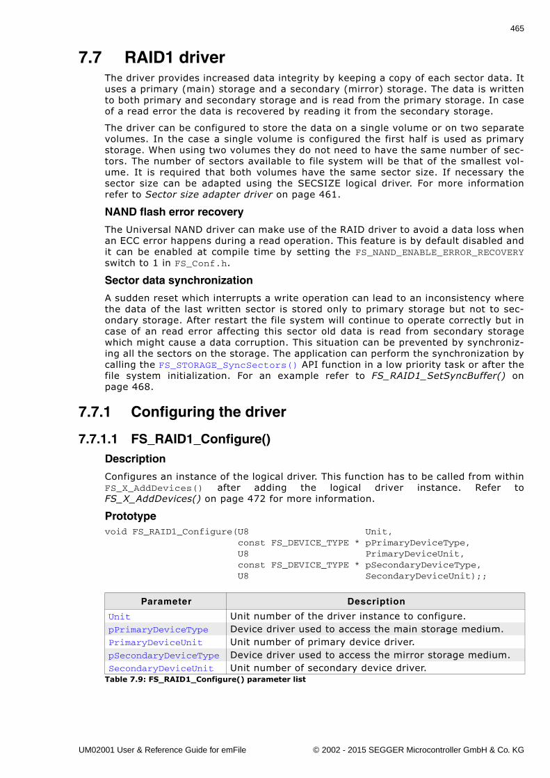
465
7.7 RAID1 driverThe driver provides increased data integrity by keeping a copy of each sector data. Ituses a primary (main) storage and a secondary (mirror) storage. The data is writtento both primary and secondary storage and is read from the primary storage. In caseof a read error the data is recovered by reading it from the secondary storage.
The driver can be configured to store the data on a single volume or on two separatevolumes. In the case a single volume is configured the first half is used as primarystorage. When using two volumes they do not need to have the same number of sec-tors. The number of sectors available to file system will be that of the smallest vol-ume. It is required that both volumes have the same sector size. If necessary thesector size can be adapted using the SECSIZE logical driver. For more informationrefer to Sector size adapter driver on page 461.
NAND flash error recovery
The Universal NAND driver can make use of the RAID driver to avoid a data loss whenan ECC error happens during a read operation. This feature is by default disabled andit can be enabled at compile time by setting the FS_NAND_ENABLE_ERROR_RECOVERYswitch to 1 in FS_Conf.h.
Sector data synchronization
A sudden reset which interrupts a write operation can lead to an inconsistency wherethe data of the last written sector is stored only to primary storage but not to sec-ondary storage. After restart the file system will continue to operate correctly but incase of an read error affecting this sector old data is read from secondary storagewhich might cause a data corruption. This situation can be prevented by synchroniz-ing all the sectors on the storage. The application can perform the synchronization bycalling the FS_STORAGE_SyncSectors() API function in a low priority task or after thefile system initialization. For an example refer to FS_RAID1_SetSyncBuffer() onpage 468.
7.7.1 Configuring the driver
7.7.1.1 FS_RAID1_Configure()Description
Configures an instance of the logical driver. This function has to be called from withinFS_X_AddDevices() after adding the logical driver instance. Refer toFS_X_AddDevices() on page 472 for more information.
Prototypevoid FS_RAID1_Configure(U8 Unit, const FS_DEVICE_TYPE * pPrimaryDeviceType, U8 PrimaryDeviceUnit, const FS_DEVICE_TYPE * pSecondaryDeviceType, U8 SecondaryDeviceUnit);;
Parameter Description
Unit Unit number of the driver instance to configure.pPrimaryDeviceType Device driver used to access the main storage medium.PrimaryDeviceUnit Unit number of primary device driver.pSecondaryDeviceType Device driver used to access the mirror storage medium.SecondaryDeviceUnit Unit number of secondary device driver.
Table 7.9: FS_RAID1_Configure() parameter list
UM02001 User & Reference Guide for emFile © 2002 - 2015 SEGGER Microcontroller GmbH & Co. KG
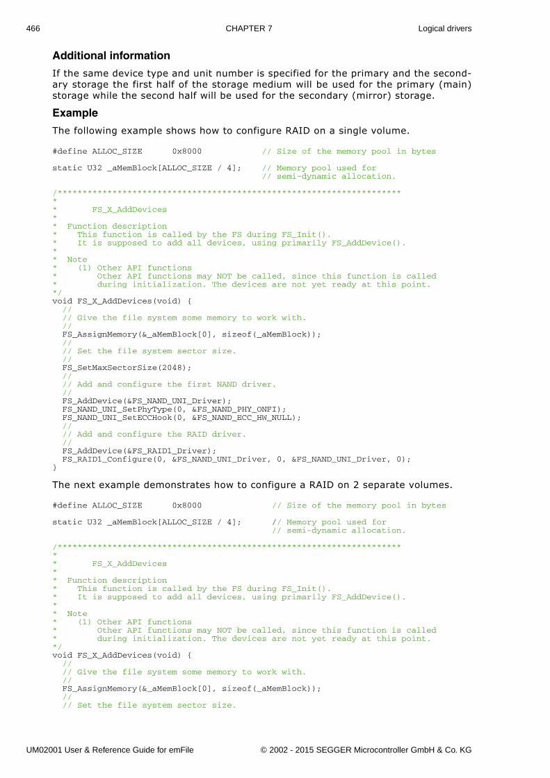
466 CHAPTER 7 Logical drivers
Additional information
If the same device type and unit number is specified for the primary and the second-ary storage the first half of the storage medium will be used for the primary (main)storage while the second half will be used for the secondary (mirror) storage.
Example
The following example shows how to configure RAID on a single volume.
#define ALLOC_SIZE 0x8000 // Size of the memory pool in bytes
static U32 _aMemBlock[ALLOC_SIZE / 4]; // Memory pool used for // semi-dynamic allocation.
/*********************************************************************** FS_X_AddDevices** Function description* This function is called by the FS during FS_Init().* It is supposed to add all devices, using primarily FS_AddDevice().* * Note* (1) Other API functions* Other API functions may NOT be called, since this function is called* during initialization. The devices are not yet ready at this point.*/void FS_X_AddDevices(void) { // // Give the file system some memory to work with. // FS_AssignMemory(&_aMemBlock[0], sizeof(_aMemBlock)); // // Set the file system sector size. // FS_SetMaxSectorSize(2048); // // Add and configure the first NAND driver. // FS_AddDevice(&FS_NAND_UNI_Driver); FS_NAND_UNI_SetPhyType(0, &FS_NAND_PHY_ONFI); FS_NAND_UNI_SetECCHook(0, &FS_NAND_ECC_HW_NULL); // // Add and configure the RAID driver. // FS_AddDevice(&FS_RAID1_Driver); FS_RAID1_Configure(0, &FS_NAND_UNI_Driver, 0, &FS_NAND_UNI_Driver, 0);}
The next example demonstrates how to configure a RAID on 2 separate volumes.
#define ALLOC_SIZE 0x8000 // Size of the memory pool in bytes
static U32 _aMemBlock[ALLOC_SIZE / 4]; // Memory pool used for // semi-dynamic allocation.
/*********************************************************************** FS_X_AddDevices** Function description* This function is called by the FS during FS_Init().* It is supposed to add all devices, using primarily FS_AddDevice().* * Note* (1) Other API functions* Other API functions may NOT be called, since this function is called* during initialization. The devices are not yet ready at this point.*/void FS_X_AddDevices(void) { // // Give the file system some memory to work with. // FS_AssignMemory(&_aMemBlock[0], sizeof(_aMemBlock)); // // Set the file system sector size.
UM02001 User & Reference Guide for emFile © 2002 - 2015 SEGGER Microcontroller GmbH & Co. KG
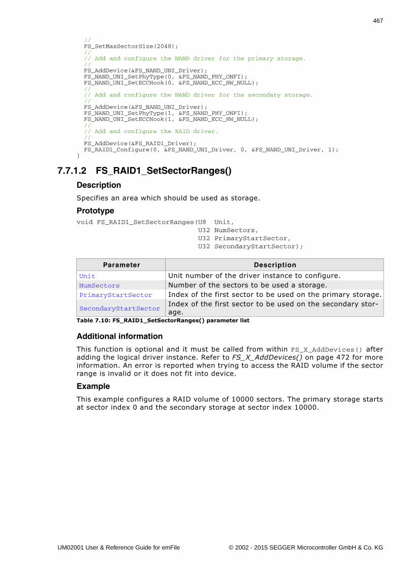
467
// FS_SetMaxSectorSize(2048); // // Add and configure the NAND driver for the primary storage. // FS_AddDevice(&FS_NAND_UNI_Driver); FS_NAND_UNI_SetPhyType(0, &FS_NAND_PHY_ONFI); FS_NAND_UNI_SetECCHook(0, &FS_NAND_ECC_HW_NULL); // // Add and configure the NAND driver for the secondary storage. // FS_AddDevice(&FS_NAND_UNI_Driver); FS_NAND_UNI_SetPhyType(1, &FS_NAND_PHY_ONFI); FS_NAND_UNI_SetECCHook(1, &FS_NAND_ECC_HW_NULL); // // Add and configure the RAID driver. // FS_AddDevice(&FS_RAID1_Driver); FS_RAID1_Configure(0, &FS_NAND_UNI_Driver, 0, &FS_NAND_UNI_Driver, 1);}
7.7.1.2 FS_RAID1_SetSectorRanges()Description
Specifies an area which should be used as storage.
Prototypevoid FS_RAID1_SetSectorRanges(U8 Unit, U32 NumSectors, U32 PrimaryStartSector, U32 SecondaryStartSector);
Additional information
This function is optional and it must be called from within FS_X_AddDevices() afteradding the logical driver instance. Refer to FS_X_AddDevices() on page 472 for moreinformation. An error is reported when trying to access the RAID volume if the sectorrange is invalid or it does not fit into device.
Example
This example configures a RAID volume of 10000 sectors. The primary storage startsat sector index 0 and the secondary storage at sector index 10000.
Parameter Description
Unit Unit number of the driver instance to configure.NumSectors Number of the sectors to be used a storage.PrimaryStartSector Index of the first sector to be used on the primary storage.
SecondaryStartSectorIndex of the first sector to be used on the secondary stor-age.
Table 7.10: FS_RAID1_SetSectorRanges() parameter list
UM02001 User & Reference Guide for emFile © 2002 - 2015 SEGGER Microcontroller GmbH & Co. KG
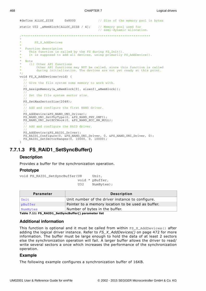
468 CHAPTER 7 Logical drivers
#define ALLOC_SIZE 0x8000 // Size of the memory pool in bytes
static U32 _aMemBlock[ALLOC_SIZE / 4]; // Memory pool used for // semi-dynamic allocation.
/*********************************************************************** FS_X_AddDevices** Function description* This function is called by the FS during FS_Init().* It is supposed to add all devices, using primarily FS_AddDevice().* * Note* (1) Other API functions* Other API functions may NOT be called, since this function is called* during initialization. The devices are not yet ready at this point.*/void FS_X_AddDevices(void) { // // Give the file system some memory to work with. // FS_AssignMemory(&_aMemBlock[0], sizeof(_aMemBlock)); // // Set the file system sector size. // FS_SetMaxSectorSize(2048); // // Add and configure the first NAND driver. // FS_AddDevice(&FS_NAND_UNI_Driver); FS_NAND_UNI_SetPhyType(0, &FS_NAND_PHY_ONFI); FS_NAND_UNI_SetECCHook(0, &FS_NAND_ECC_HW_NULL); // // Add and configure the RAID driver. // FS_AddDevice(&FS_RAID1_Driver); FS_RAID1_Configure(0, &FS_NAND_UNI_Driver, 0, &FS_NAND_UNI_Driver, 0); FS_RAID1_SetSectorRanges(0, 10000, 0, 10000);}
7.7.1.3 FS_RAID1_SetSyncBuffer()Description
Provides a buffer for the synchronization operation.
Prototypevoid FS_RAID1_SetSyncBuffer(U8 Unit, void * pBuffer, U32 NumBytes);
Additional information
This function is optional and it must be called from within FS_X_AddDevices() afteradding the logical driver instance. Refer to FS_X_AddDevices() on page 472 for moreinformation. The buffer must be large enough to hold the data of at least 2 sectorselse the synchronization operation will fail. A larger buffer allows the driver to read/write several sectors a once which increases the performance of the synchronizationoperation.
Example
The following example configures a synchronization buffer of 16KB.
Parameter Description
Unit Unit number of the driver instance to configure.pBuffer Pointer to a memory location to be used as buffer.NumBytes Number of bytes in the buffer.
Table 7.11: FS_RAID1_SetSyncBuffer() parameter list
UM02001 User & Reference Guide for emFile © 2002 - 2015 SEGGER Microcontroller GmbH & Co. KG
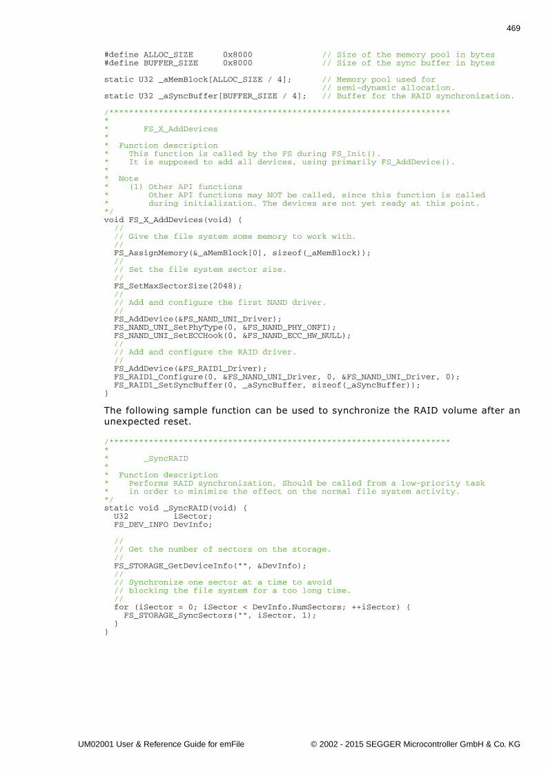
469
#define ALLOC_SIZE 0x8000 // Size of the memory pool in bytes#define BUFFER_SIZE 0x8000 // Size of the sync buffer in bytes
static U32 _aMemBlock[ALLOC_SIZE / 4]; // Memory pool used for // semi-dynamic allocation.static U32 _aSyncBuffer[BUFFER_SIZE / 4]; // Buffer for the RAID synchronization.
/*********************************************************************** FS_X_AddDevices** Function description* This function is called by the FS during FS_Init().* It is supposed to add all devices, using primarily FS_AddDevice().* * Note* (1) Other API functions* Other API functions may NOT be called, since this function is called* during initialization. The devices are not yet ready at this point.*/void FS_X_AddDevices(void) { // // Give the file system some memory to work with. // FS_AssignMemory(&_aMemBlock[0], sizeof(_aMemBlock)); // // Set the file system sector size. // FS_SetMaxSectorSize(2048); // // Add and configure the first NAND driver. // FS_AddDevice(&FS_NAND_UNI_Driver); FS_NAND_UNI_SetPhyType(0, &FS_NAND_PHY_ONFI); FS_NAND_UNI_SetECCHook(0, &FS_NAND_ECC_HW_NULL); // // Add and configure the RAID driver. // FS_AddDevice(&FS_RAID1_Driver); FS_RAID1_Configure(0, &FS_NAND_UNI_Driver, 0, &FS_NAND_UNI_Driver, 0); FS_RAID1_SetSyncBuffer(0, _aSyncBuffer, sizeof(_aSyncBuffer));}
The following sample function can be used to synchronize the RAID volume after anunexpected reset.
/*********************************************************************** _SyncRAID** Function description* Performs RAID synchronization, Should be called from a low-priority task* in order to minimize the effect on the normal file system activity.*/static void _SyncRAID(void) { U32 iSector; FS_DEV_INFO DevInfo;
// // Get the number of sectors on the storage. // FS_STORAGE_GetDeviceInfo("", &DevInfo); // // Synchronize one sector at a time to avoid // blocking the file system for a too long time. // for (iSector = 0; iSector < DevInfo.NumSectors; ++iSector) { FS_STORAGE_SyncSectors("", iSector, 1); }}
UM02001 User & Reference Guide for emFile © 2002 - 2015 SEGGER Microcontroller GmbH & Co. KG
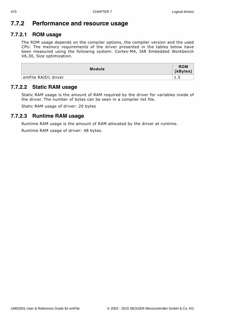
470 CHAPTER 7 Logical drivers
7.7.2 Performance and resource usage
7.7.2.1 ROM usageThe ROM usage depends on the compiler options, the compiler version and the usedCPU. The memory requirements of the driver presented in the tables below havebeen measured using the following system: Cortex-M4, IAR Embedded WorkbenchV6.30, Size optimization.
7.7.2.2 Static RAM usageStatic RAM usage is the amount of RAM required by the driver for variables inside ofthe driver. The number of bytes can be seen in a compiler list file.
Static RAM usage of driver: 20 bytes
7.7.2.3 Runtime RAM usageRuntime RAM usage is the amount of RAM allocated by the driver at runtime.
Runtime RAM usage of driver: 48 bytes.
ModuleROM
[kBytes]
emFile RAID1 driver 1.5
UM02001 User & Reference Guide for emFile © 2002 - 2015 SEGGER Microcontroller GmbH & Co. KG
471
Chapter 8
Configuration of emFile
emFile can be used without the need for changing any of the compile time flags. Allcompile time configuration flags are preconfigured with valid values, which matchesthe requirements of the most applications. Device drivers can be added at runtime.
The default configuration of emFile can be changed via compile time flags which canbe added to FS_Conf.h. This is the main configuration file for the file system.
Every driver folder includes a configuration file (e.g. FS_ConfigRamDisk.c) withimplementations of runtime configuration functions explained in this chapter. Theconfiguration files are a good start, to run emFile �out of the box�.
UM02001 User & Reference Guide for emFile © 2002 - 2015 SEGGER Microcontroller GmbH & Co. KG
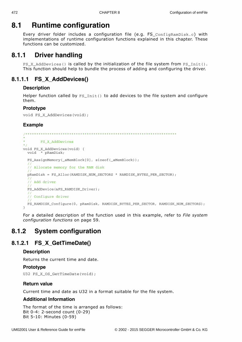
472 CHAPTER 8 Configuration of emFile
8.1 Runtime configurationEvery driver folder includes a configuration file (e.g. FS_ConfigRamDisk.c) withimplementations of runtime configuration functions explained in this chapter. Thesefunctions can be customized.
8.1.1 Driver handlingFS_X_AddDevices() is called by the initialization of the file system from FS_Init().This function should help to bundle the process of adding and configuring the driver.
8.1.1.1 FS_X_AddDevices()Description
Helper function called by FS_Init() to add devices to the file system and configurethem.
Prototypevoid FS_X_AddDevices(void);
Example
/*********************************************************************** FS_X_AddDevices*/void FS_X_AddDevices(void) { void * pRamDisk;
FS_AssignMemory(_aMemBlock[0], sizeof(_aMemBlock)); // // Allocate memory for the RAM disk // pRamDisk = FS_Alloc(RAMDISK_NUM_SECTORS * RAMDISK_BYTES_PER_SECTOR); // // Add driver // FS_AddDevice(&FS_RAMDISK_Driver); // // Configure driver // FS_RAMDISK_Configure(0, pRamDisk, RAMDISK_BYTES_PER_SECTOR, RAMDISK_NUM_SECTORS);}
For a detailed description of the function used in this example, refer to File systemconfiguration functions on page 59.
8.1.2 System configuration
8.1.2.1 FS_X_GetTimeDate()Description
Returns the current time and date.
PrototypeU32 FS_X_OS_GetTimeDate(void);
Return value
Current time and date as U32 in a format suitable for the file system.
Additional Information
The format of the time is arranged as follows:Bit 0-4: 2-second count (0-29)Bit 5-10: Minutes (0-59)
UM02001 User & Reference Guide for emFile © 2002 - 2015 SEGGER Microcontroller GmbH & Co. KG
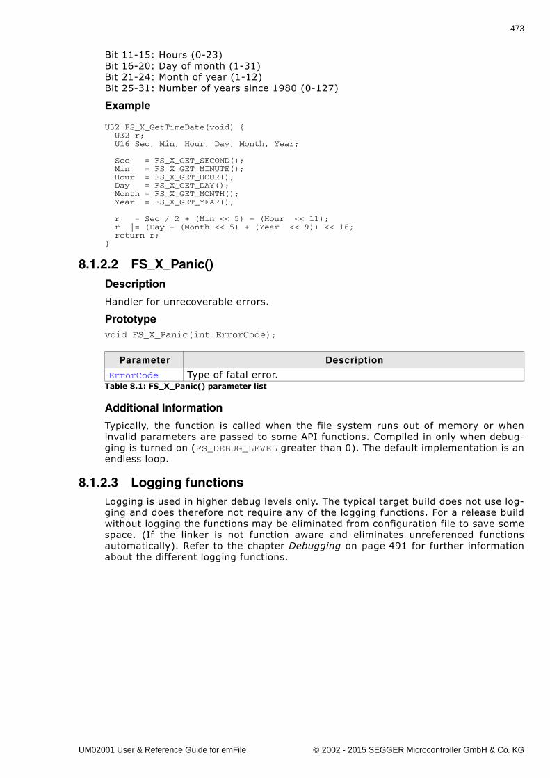
473
Bit 11-15: Hours (0-23)Bit 16-20: Day of month (1-31)Bit 21-24: Month of year (1-12)Bit 25-31: Number of years since 1980 (0-127)
Example
U32 FS_X_GetTimeDate(void) { U32 r; U16 Sec, Min, Hour, Day, Month, Year;
Sec = FS_X_GET_SECOND(); Min = FS_X_GET_MINUTE(); Hour = FS_X_GET_HOUR(); Day = FS_X_GET_DAY(); Month = FS_X_GET_MONTH(); Year = FS_X_GET_YEAR();
r = Sec / 2 + (Min << 5) + (Hour << 11); r |= (Day + (Month << 5) + (Year << 9)) << 16; return r;}
8.1.2.2 FS_X_Panic()Description
Handler for unrecoverable errors.
Prototypevoid FS_X_Panic(int ErrorCode);
Additional Information
Typically, the function is called when the file system runs out of memory or wheninvalid parameters are passed to some API functions. Compiled in only when debug-ging is turned on (FS_DEBUG_LEVEL greater than 0). The default implementation is anendless loop.
8.1.2.3 Logging functionsLogging is used in higher debug levels only. The typical target build does not use log-ging and does therefore not require any of the logging functions. For a release buildwithout logging the functions may be eliminated from configuration file to save somespace. (If the linker is not function aware and eliminates unreferenced functionsautomatically). Refer to the chapter Debugging on page 491 for further informationabout the different logging functions.
Parameter Description
ErrorCode Type of fatal error.Table 8.1: FS_X_Panic() parameter list
UM02001 User & Reference Guide for emFile © 2002 - 2015 SEGGER Microcontroller GmbH & Co. KG
474 CHAPTER 8 Configuration of emFile
8.2 Compile time configurationThe following types of configuration macros exist:
Binary switches “B”
Switches can have a value of either 0 or 1, for deactivated and activated respectively.Actually, anything other than 0 works, but 1 makes it easier to read a configurationfile. These switches can enable or disable a certain functionality or behavior.Switches are the simplest form of configuration macros.
Numerical values “N”
Numerical values are used somewhere in the code in place of a numerical constant. Atypical example is the configuration of the sector size of a storage medium.
UM02001 User & Reference Guide for emFile © 2002 - 2015 SEGGER Microcontroller GmbH & Co. KG
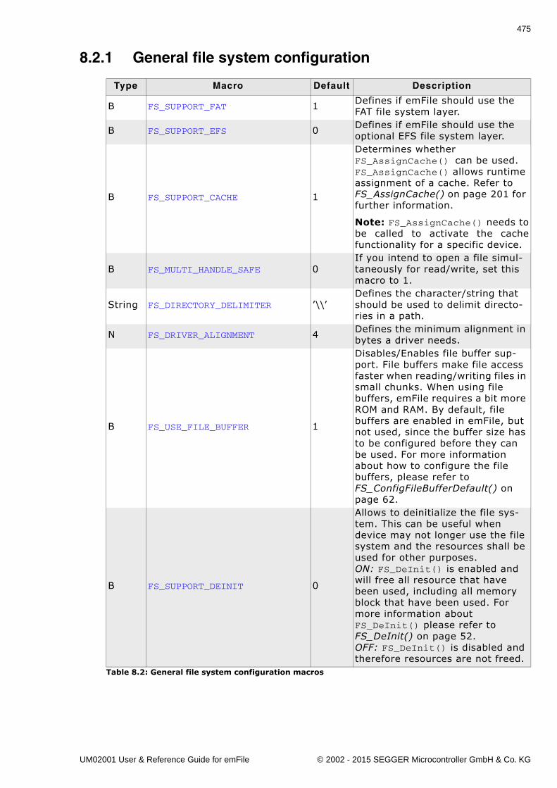
475
8.2.1 General file system configuration
Type Macro Default Description
B FS_SUPPORT_FAT 1 Defines if emFile should use the FAT file system layer.
B FS_SUPPORT_EFS 0 Defines if emFile should use the optional EFS file system layer.
B FS_SUPPORT_CACHE 1
Determines whether FS_AssignCache() can be used. FS_AssignCache() allows runtime assignment of a cache. Refer to FS_AssignCache() on page 201 for further information.
Note: FS_AssignCache() needs tobe called to activate the cachefunctionality for a specific device.
B FS_MULTI_HANDLE_SAFE 0If you intend to open a file simul-taneously for read/write, set this macro to 1.
String FS_DIRECTORY_DELIMITER �\\�Defines the character/string that should be used to delimit directo-ries in a path.
N FS_DRIVER_ALIGNMENT 4 Defines the minimum alignment in bytes a driver needs.
B FS_USE_FILE_BUFFER 1
Disables/Enables file buffer sup-port. File buffers make file access faster when reading/writing files in small chunks. When using file buffers, emFile requires a bit more ROM and RAM. By default, file buffers are enabled in emFile, but not used, since the buffer size has to be configured before they can be used. For more information about how to configure the file buffers, please refer to FS_ConfigFileBufferDefault() on page 62.
B FS_SUPPORT_DEINIT 0
Allows to deinitialize the file sys-tem. This can be useful when device may not longer use the file system and the resources shall be used for other purposes.ON: FS_DeInit() is enabled and will free all resource that have been used, including all memory block that have been used. For more information about FS_DeInit() please refer to FS_DeInit() on page 52.OFF: FS_DeInit() is disabled and therefore resources are not freed.
Table 8.2: General file system configuration macros
UM02001 User & Reference Guide for emFile © 2002 - 2015 SEGGER Microcontroller GmbH & Co. KG
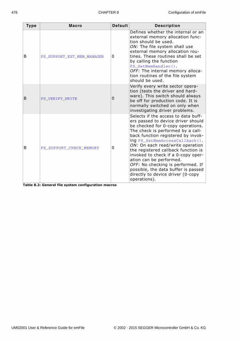
476 CHAPTER 8 Configuration of emFile
B FS_SUPPORT_EXT_MEM_MANAGER 0
Defines whether the internal or an external memory allocation func-tion should be used.ON: The file system shall use external memory allocation rou-tines. These routines shall be set by calling the function FS_SetMemHandler().OFF: The internal memory alloca-tion routines of the file system should be used.
B FS_VERIFY_WRITE 0
Verify every write sector opera-tion (tests the driver and hard-ware). This switch should always be off for production code. It is normally switched on only when investigating driver problems.
B FS_SUPPORT_CHECK_MEMORY 0
Selects if the access to data buff-ers passed to device driver should be checked for 0-copy operations. The check is performed by a call-back function registered by invok-ing FS_SetMemAccessCallback().ON: On each read/write operation the registered callback function is invoked to check if a 0-copy oper-ation can be performed.OFF: No checking is performed. If possible, the data buffer is passed directly to device driver (0-copy operations).
Type Macro Default Description
Table 8.2: General file system configuration macros
UM02001 User & Reference Guide for emFile © 2002 - 2015 SEGGER Microcontroller GmbH & Co. KG
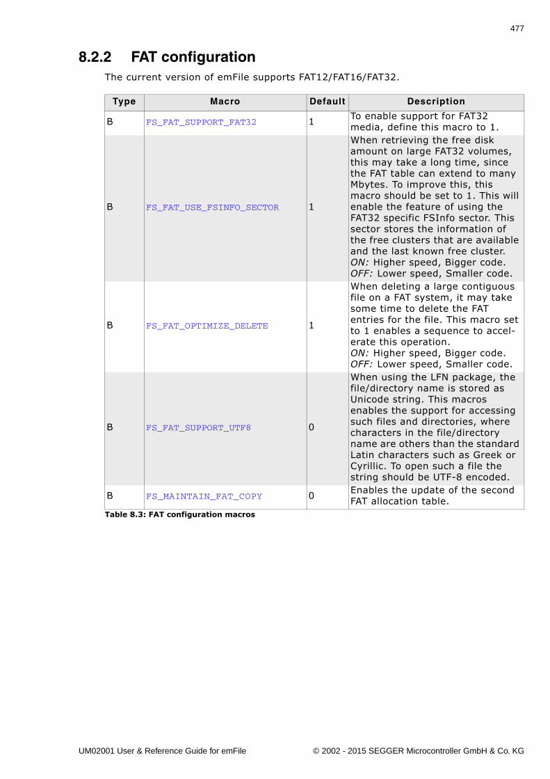
477
8.2.2 FAT configurationThe current version of emFile supports FAT12/FAT16/FAT32.
Type Macro Default Description
B FS_FAT_SUPPORT_FAT32 1 To enable support for FAT32 media, define this macro to 1.
B FS_FAT_USE_FSINFO_SECTOR 1
When retrieving the free disk amount on large FAT32 volumes, this may take a long time, since the FAT table can extend to many Mbytes. To improve this, this macro should be set to 1. This will enable the feature of using the FAT32 specific FSInfo sector. This sector stores the information of the free clusters that are available and the last known free cluster.ON: Higher speed, Bigger code.OFF: Lower speed, Smaller code.
B FS_FAT_OPTIMIZE_DELETE 1
When deleting a large contiguous file on a FAT system, it may take some time to delete the FAT entries for the file. This macro set to 1 enables a sequence to accel-erate this operation.ON: Higher speed, Bigger code.OFF: Lower speed, Smaller code.
B FS_FAT_SUPPORT_UTF8 0
When using the LFN package, the file/directory name is stored as Unicode string. This macros enables the support for accessing such files and directories, where characters in the file/directory name are others than the standard Latin characters such as Greek or Cyrillic. To open such a file the string should be UTF-8 encoded.
B FS_MAINTAIN_FAT_COPY 0 Enables the update of the second FAT allocation table.
Table 8.3: FAT configuration macros
UM02001 User & Reference Guide for emFile © 2002 - 2015 SEGGER Microcontroller GmbH & Co. KG
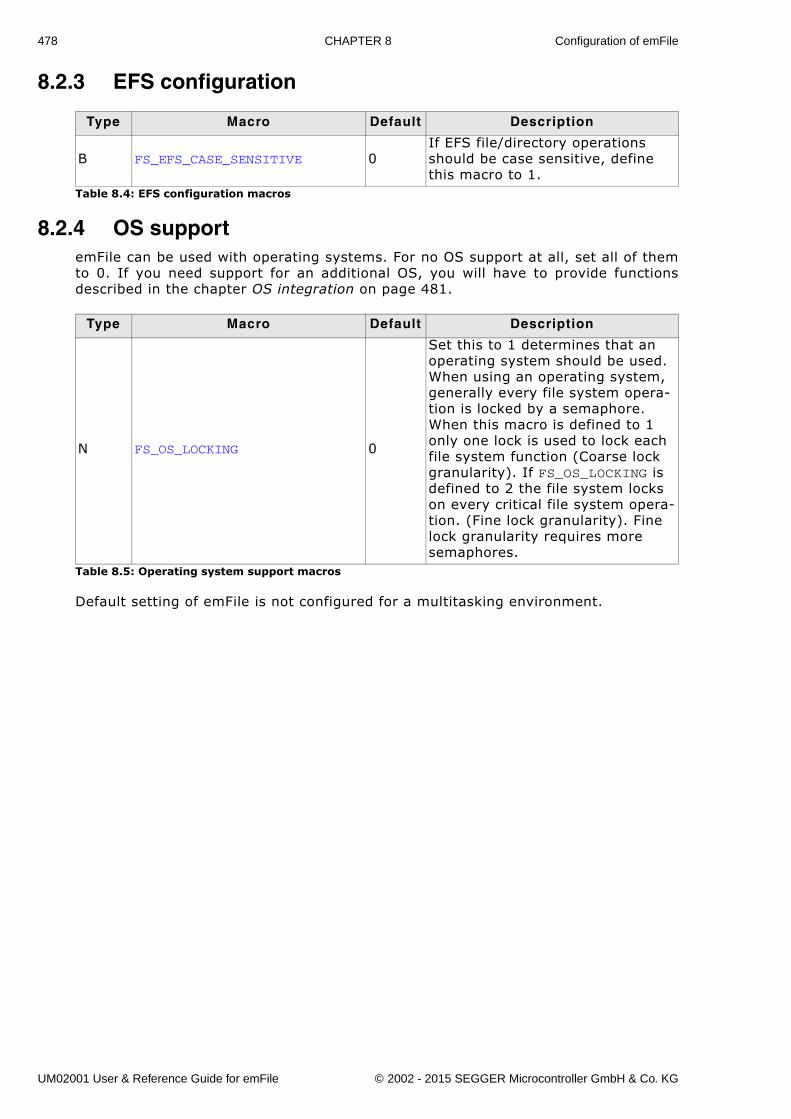
478 CHAPTER 8 Configuration of emFile
8.2.3 EFS configuration
8.2.4 OS supportemFile can be used with operating systems. For no OS support at all, set all of themto 0. If you need support for an additional OS, you will have to provide functionsdescribed in the chapter OS integration on page 481.
Default setting of emFile is not configured for a multitasking environment.
Type Macro Default Description
B FS_EFS_CASE_SENSITIVE 0If EFS file/directory operations should be case sensitive, define this macro to 1.
Table 8.4: EFS configuration macros
Type Macro Default Description
N FS_OS_LOCKING 0
Set this to 1 determines that an operating system should be used. When using an operating system, generally every file system opera-tion is locked by a semaphore. When this macro is defined to 1 only one lock is used to lock each file system function (Coarse lock granularity). If FS_OS_LOCKING is defined to 2 the file system locks on every critical file system opera-tion. (Fine lock granularity). Fine lock granularity requires more semaphores.
Table 8.5: Operating system support macros
UM02001 User & Reference Guide for emFile © 2002 - 2015 SEGGER Microcontroller GmbH & Co. KG
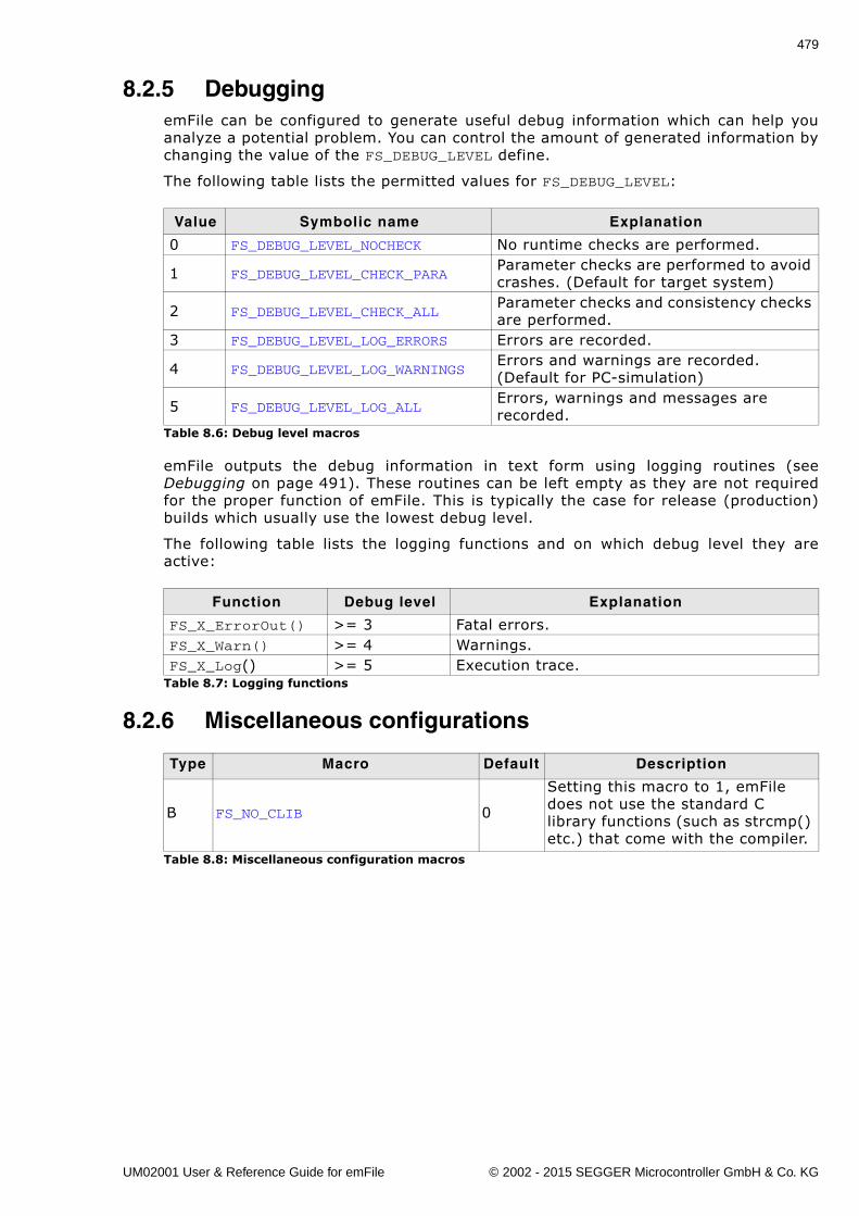
479
8.2.5 DebuggingemFile can be configured to generate useful debug information which can help youanalyze a potential problem. You can control the amount of generated information bychanging the value of the FS_DEBUG_LEVEL define.
The following table lists the permitted values for FS_DEBUG_LEVEL:
emFile outputs the debug information in text form using logging routines (seeDebugging on page 491). These routines can be left empty as they are not requiredfor the proper function of emFile. This is typically the case for release (production)builds which usually use the lowest debug level.
The following table lists the logging functions and on which debug level they areactive:
8.2.6 Miscellaneous configurations
Value Symbolic name Explanation
0 FS_DEBUG_LEVEL_NOCHECK No runtime checks are performed.
1 FS_DEBUG_LEVEL_CHECK_PARAParameter checks are performed to avoid crashes. (Default for target system)
2 FS_DEBUG_LEVEL_CHECK_ALLParameter checks and consistency checks are performed.
3 FS_DEBUG_LEVEL_LOG_ERRORS Errors are recorded.
4 FS_DEBUG_LEVEL_LOG_WARNINGSErrors and warnings are recorded. (Default for PC-simulation)
5 FS_DEBUG_LEVEL_LOG_ALLErrors, warnings and messages are recorded.
Table 8.6: Debug level macros
Function Debug level Explanation
FS_X_ErrorOut() >= 3 Fatal errors.FS_X_Warn() >= 4 Warnings.FS_X_Log() >= 5 Execution trace.
Table 8.7: Logging functions
Type Macro Default Description
B FS_NO_CLIB 0
Setting this macro to 1, emFile does not use the standard C library functions (such as strcmp() etc.) that come with the compiler.
Table 8.8: Miscellaneous configuration macros
UM02001 User & Reference Guide for emFile © 2002 - 2015 SEGGER Microcontroller GmbH & Co. KG
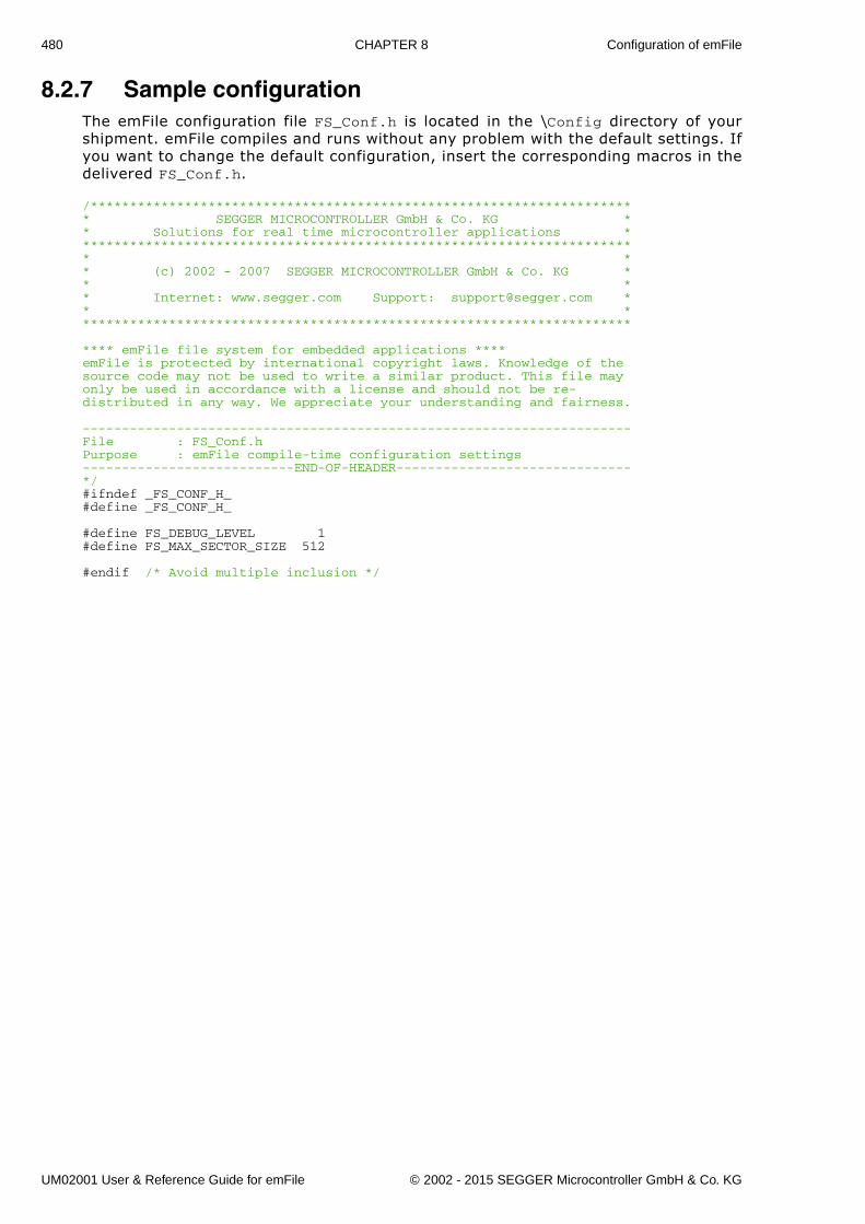
480 CHAPTER 8 Configuration of emFile
8.2.7 Sample configurationThe emFile configuration file FS_Conf.h is located in the \Config directory of yourshipment. emFile compiles and runs without any problem with the default settings. Ifyou want to change the default configuration, insert the corresponding macros in thedelivered FS_Conf.h.
/********************************************************************** SEGGER MICROCONTROLLER GmbH & Co. KG ** Solutions for real time microcontroller applications ************************************************************************ ** (c) 2002 - 2007 SEGGER MICROCONTROLLER GmbH & Co. KG ** ** Internet: www.segger.com Support: [email protected] ** ***********************************************************************
**** emFile file system for embedded applications ****emFile is protected by international copyright laws. Knowledge of thesource code may not be used to write a similar product. This file mayonly be used in accordance with a license and should not be re-distributed in any way. We appreciate your understanding and fairness.
----------------------------------------------------------------------File : FS_Conf.h Purpose : emFile compile-time configuration settings---------------------------END-OF-HEADER------------------------------*/#ifndef _FS_CONF_H_#define _FS_CONF_H_
#define FS_DEBUG_LEVEL 1#define FS_MAX_SECTOR_SIZE 512
#endif /* Avoid multiple inclusion */
UM02001 User & Reference Guide for emFile © 2002 - 2015 SEGGER Microcontroller GmbH & Co. KG
481
Chapter 9
OS integration
emFile is suitable for any multithreaded environment. To ensure that different taskscan access the file system concurrently, you need to implement a few operating sys-tem-dependent functions.
For embOS and MS Windows, you will find implementations of these functions in thefile system's source code. This chapter provides descriptions of the functionsrequired to fully support emFile in multithreaded environments. If you do not use anOS, or if you do not make file access from different tasks, you can leave these func-tions empty.
You may also add date and time support functions for use by the FAT file system. Thesample implementations provided with emFile use ANSI C standard functions toobtain the correct date and time.
UM02001 User & Reference Guide for emFile © 2002 - 2015 SEGGER Microcontroller GmbH & Co. KG
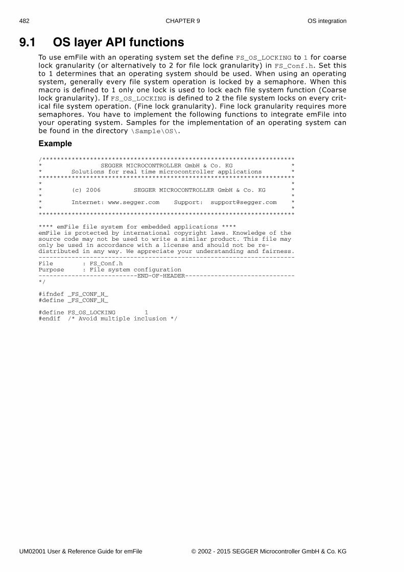
482 CHAPTER 9 OS integration
9.1 OS layer API functionsTo use emFile with an operating system set the define FS_OS_LOCKING to 1 for coarselock granularity (or alternatively to 2 for file lock granularity) in FS_Conf.h. Set thisto 1 determines that an operating system should be used. When using an operatingsystem, generally every file system operation is locked by a semaphore. When thismacro is defined to 1 only one lock is used to lock each file system function (Coarselock granularity). If FS_OS_LOCKING is defined to 2 the file system locks on every crit-ical file system operation. (Fine lock granularity). Fine lock granularity requires moresemaphores. You have to implement the following functions to integrate emFile intoyour operating system. Samples for the implementation of an operating system canbe found in the directory \Sample\OS\.
Example
/********************************************************************** SEGGER MICROCONTROLLER GmbH & Co. KG ** Solutions for real time microcontroller applications ************************************************************************ ** (c) 2006 SEGGER MICROCONTROLLER GmbH & Co. KG ** ** Internet: www.segger.com Support: [email protected] ** ***********************************************************************
**** emFile file system for embedded applications ****emFile is protected by international copyright laws. Knowledge of thesource code may not be used to write a similar product. This file mayonly be used in accordance with a license and should not be re-distributed in any way. We appreciate your understanding and fairness.----------------------------------------------------------------------File : FS_Conf.hPurpose : File system configuration---------------------------END-OF-HEADER------------------------------*/
#ifndef _FS_CONF_H_#define _FS_CONF_H_
#define FS_OS_LOCKING 1#endif /* Avoid multiple inclusion */
UM02001 User & Reference Guide for emFile © 2002 - 2015 SEGGER Microcontroller GmbH & Co. KG
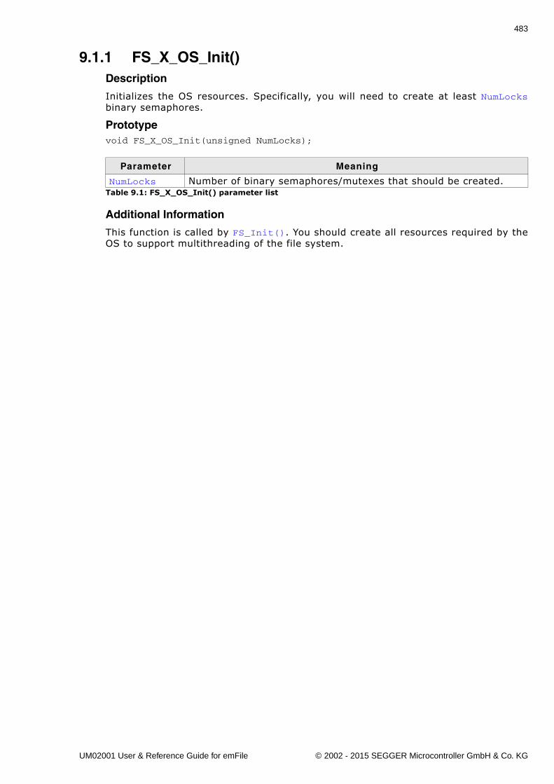
483
9.1.1 FS_X_OS_Init()Description
Initializes the OS resources. Specifically, you will need to create at least NumLocksbinary semaphores.
Prototypevoid FS_X_OS_Init(unsigned NumLocks);
Additional Information
This function is called by FS_Init(). You should create all resources required by theOS to support multithreading of the file system.
Parameter Meaning
NumLocks Number of binary semaphores/mutexes that should be created.Table 9.1: FS_X_OS_Init() parameter list
UM02001 User & Reference Guide for emFile © 2002 - 2015 SEGGER Microcontroller GmbH & Co. KG
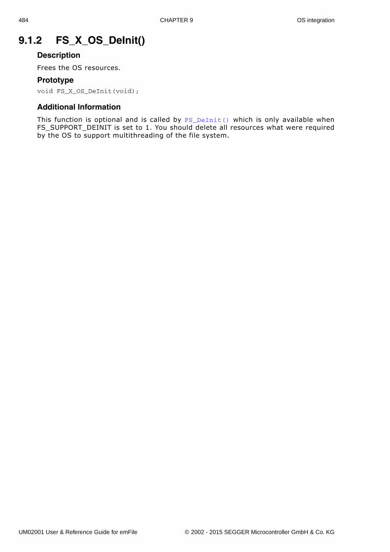
484 CHAPTER 9 OS integration
9.1.2 FS_X_OS_DeInit()Description
Frees the OS resources.
Prototypevoid FS_X_OS_DeInit(void);
Additional Information
This function is optional and is called by FS_DeInit() which is only available whenFS_SUPPORT_DEINIT is set to 1. You should delete all resources what were requiredby the OS to support multithreading of the file system.
UM02001 User & Reference Guide for emFile © 2002 - 2015 SEGGER Microcontroller GmbH & Co. KG
485
9.1.3 FS_X_OS_Lock()Description
Locks a specific file system operation.
Prototypevoid FS_X_OS_Lock(unsigned LockIndex);
Additional Information
This routine is called by the file system before it accesses the device or before usinga critical internal data structure. It blocks other threads from entering the same crit-ical section using a resource semaphore/mutex until FS_X_OS_Unlock() has beencalled with the same LockIndex.When using a real time operating system, you normally have to increment a countingresource semaphore.
Parameter Meaning
LockIndexIndex number of the binary semaphore/mutex created before in FS_X_OS_Init().
Table 9.2: FS_X_OS_Lock() parameter list
UM02001 User & Reference Guide for emFile © 2002 - 2015 SEGGER Microcontroller GmbH & Co. KG
486 CHAPTER 9 OS integration
9.1.4 FS_X_OS_Unlock()Description
Unlocks a file system operation.
Prototypevoid FS_X_OS_Unlock(unsigned LockIndex);
Additional Information
This routine is called by the file system after accessing the device or after using acritical internal data structure. When using a real time operating system, you nor-mally have to decrement a counting resource semaphore.
Parameter Meaning
LockIndexIndex number of the binary semaphore/mutex created before in FS_X_OS_Init().
Table 9.3: FS_X_OS_Unlock() parameter list
UM02001 User & Reference Guide for emFile © 2002 - 2015 SEGGER Microcontroller GmbH & Co. KG
487
9.1.5 FS_X_OS_Wait()Description
Blocks the calling task for a specified time or until the file system event is triggered.
Prototypevoid FS_X_OS_Wait(int Timeout);
Additional Information
The file system has only one event which is created at the initialization in theFS_X_OS_Init() function and later released in FS_X_OS_DeInit(). The event can betriggered by calling FS_X_OS_Signal(). This routine is not called directly by the filesystem but it can be used to implement event-driven HW layers in a portable way.
Parameter Meaning
TimeoutNumber of OS ticks the function should wait for the event to be sig-naled.
Table 9.4: FS_X_OS_Wait() parameter list
UM02001 User & Reference Guide for emFile © 2002 - 2015 SEGGER Microcontroller GmbH & Co. KG
488 CHAPTER 9 OS integration
9.1.6 FS_X_OS_Signal()Description
Signals the file system event.
Prototypevoid FS_X_OS_Signal(void);
Additional Information
Typically, this routine is called from an interrupt to wake-up the task which is blockedin a call to FS_X_OS_Wait() function. This routine is not called directly by the filesystem but it can be used to implement event-driven HW layers in a portable way.
UM02001 User & Reference Guide for emFile © 2002 - 2015 SEGGER Microcontroller GmbH & Co. KG
489
9.1.7 FS_X_OS_GetTime()Description
Returns the number of OS ticks elapsed since the start of OS.
PrototypeU32 FS_X_OS_GetTime(void);
Return value
Number of OS ticks elapsed since the start of OS.
Additional Information
Typically, this function is called for performance measurements. An OS tick is usually1ms long.
UM02001 User & Reference Guide for emFile © 2002 - 2015 SEGGER Microcontroller GmbH & Co. KG
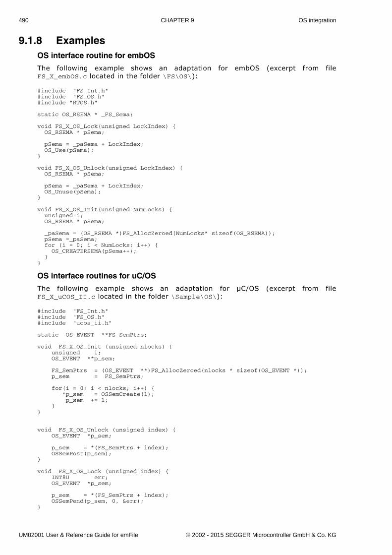
490 CHAPTER 9 OS integration
9.1.8 ExamplesOS interface routine for embOS
The following example shows an adaptation for embOS (excerpt from fileFS_X_embOS.c located in the folder \FS\OS\):
#include "FS_Int.h"#include "FS_OS.h"#include "RTOS.h"
static OS_RSEMA * _FS_Sema;
void FS_X_OS_Lock(unsigned LockIndex) { OS_RSEMA * pSema;
pSema = _paSema + LockIndex; OS_Use(pSema);}
void FS_X_OS_Unlock(unsigned LockIndex) { OS_RSEMA * pSema;
pSema = _paSema + LockIndex; OS_Unuse(pSema);}
void FS_X_OS_Init(unsigned NumLocks) { unsigned i; OS_RSEMA * pSema;
_paSema = (OS_RSEMA *)FS_AllocZeroed(NumLocks* sizeof(OS_RSEMA)); pSema =_paSema; for (i = 0; i < NumLocks; i++) { OS_CREATERSEMA(pSema++); }}
OS interface routines for uC/OS
The following example shows an adaptation for µC/OS (excerpt from fileFS_X_uCOS_II.c located in the folder \Sample\OS\):
#include "FS_Int.h"#include "FS_OS.h"#include "ucos_ii.h"
static OS_EVENT **FS_SemPtrs;
void FS_X_OS_Init (unsigned nlocks) { unsigned i; OS_EVENT **p_sem;
FS_SemPtrs = (OS_EVENT **)FS_AllocZeroed(nlocks * sizeof(OS_EVENT *)); p_sem = FS_SemPtrs;
for(i = 0; i < nlocks; i++) { *p_sem = OSSemCreate(1); p_sem += 1; }}
void FS_X_OS_Unlock (unsigned index) { OS_EVENT *p_sem;
p_sem = *(FS_SemPtrs + index); OSSemPost(p_sem);}
void FS_X_OS_Lock (unsigned index) { INT8U err; OS_EVENT *p_sem;
p_sem = *(FS_SemPtrs + index); OSSemPend(p_sem, 0, &err);}
UM02001 User & Reference Guide for emFile © 2002 - 2015 SEGGER Microcontroller GmbH & Co. KG
491
Chapter 10
Debugging
For debug purpose the functions in this chapter are helpful. The functions displayinformation on a display or through a serial communication port.
UM02001 User & Reference Guide for emFile © 2002 - 2015 SEGGER Microcontroller GmbH & Co. KG
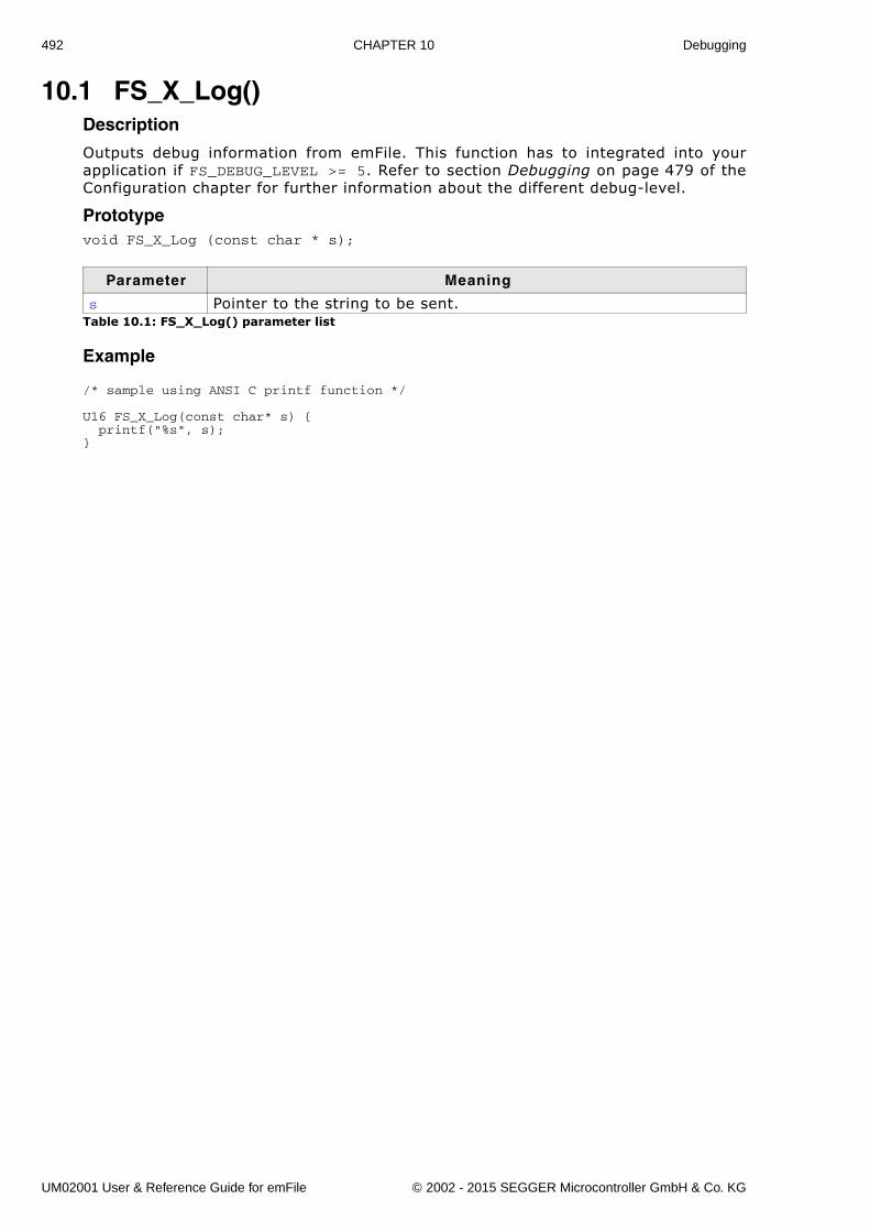
492 CHAPTER 10 Debugging
10.1 FS_X_Log()Description
Outputs debug information from emFile. This function has to integrated into yourapplication if FS_DEBUG_LEVEL >= 5. Refer to section Debugging on page 479 of theConfiguration chapter for further information about the different debug-level.
Prototypevoid FS_X_Log (const char * s);
Example
/* sample using ANSI C printf function */
U16 FS_X_Log(const char* s) { printf("%s", s);}
Parameter Meaning
s Pointer to the string to be sent.Table 10.1: FS_X_Log() parameter list
UM02001 User & Reference Guide for emFile © 2002 - 2015 SEGGER Microcontroller GmbH & Co. KG
493
10.2 FS_X_Warn()Description
Outputs warnings from emFile. This function has to integrated into your application ifFS_DEBUG_LEVEL >= 4. Refer to section Debugging on page 479 of the Configurationchapter for further information about the different debug-level.
Prototypevoid FS_X_Warn (const char * s);
Example
/* sample using ANSI C printf function */
U16 FS_X_Warn(const char* s) { printf("%s", s);}
Parameter Meaning
s Pointer to the string to be sent.Table 10.2: FS_X_Warn() parameter list
UM02001 User & Reference Guide for emFile © 2002 - 2015 SEGGER Microcontroller GmbH & Co. KG
494 CHAPTER 10 Debugging
10.3 FS_X_ErrorOut()Description
Outputs errors from emFile. This function has to integrated into your application ifFS_DEBUG_LEVEL >= 3. Refer to section Debugging on page 479 of the Configurationchapter for further information about the different debug-level.
Prototypevoid FS_X_ErrorOut (const char * s);
Example
/* sample using ANSI C printf function */
U16 FS_X_ErrorOut(const char* s) { printf("%s", s);}
Parameter Meaning
s Pointer to the string to be sent.Table 10.3: FS_X_ErrorOut() parameter list
UM02001 User & Reference Guide for emFile © 2002 - 2015 SEGGER Microcontroller GmbH & Co. KG
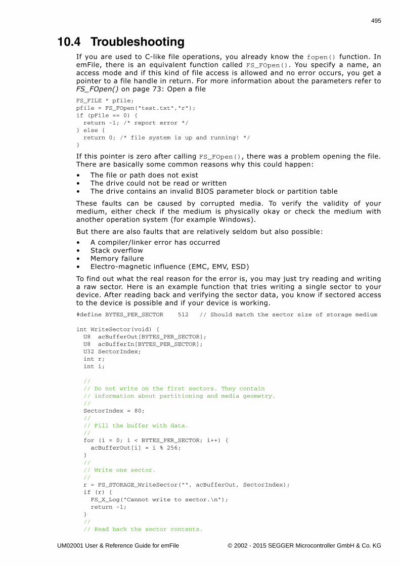
495
10.4 TroubleshootingIf you are used to C-like file operations, you already know the fopen() function. InemFile, there is an equivalent function called FS_FOpen(). You specify a name, anaccess mode and if this kind of file access is allowed and no error occurs, you get apointer to a file handle in return. For more information about the parameters refer toFS_FOpen() on page 73: Open a file
FS_FILE * pfile;pfile = FS_FOpen("test.txt","r");if (pFile == 0) { return -1; /* report error */} else { return 0; /* file system is up and running! */}
If this pointer is zero after calling FS_FOpen(), there was a problem opening the file.There are basically some common reasons why this could happen:
� The file or path does not exist� The drive could not be read or written� The drive contains an invalid BIOS parameter block or partition table
These faults can be caused by corrupted media. To verify the validity of yourmedium, either check if the medium is physically okay or check the medium withanother operation system (for example Windows).
But there are also faults that are relatively seldom but also possible:
� A compiler/linker error has occurred� Stack overflow� Memory failure� Electro-magnetic influence (EMC, EMV, ESD)
To find out what the real reason for the error is, you may just try reading and writinga raw sector. Here is an example function that tries writing a single sector to yourdevice. After reading back and verifying the sector data, you know if sectored accessto the device is possible and if your device is working.
#define BYTES_PER_SECTOR 512 // Should match the sector size of storage medium
int WriteSector(void) { U8 acBufferOut[BYTES_PER_SECTOR]; U8 acBufferIn[BYTES_PER_SECTOR]; U32 SectorIndex; int r; int i;
// // Do not write on the first sectors. They contain // information about partitioning and media geometry. // SectorIndex = 80; // // Fill the buffer with data. // for (i = 0; i < BYTES_PER_SECTOR; i++) { acBufferOut[i] = i % 256; } // // Write one sector. // r = FS_STORAGE_WriteSector("", acBufferOut, SectorIndex); if (r) { FS_X_Log("Cannot write to sector.\n"); return -1; } // // Read back the sector contents.
UM02001 User & Reference Guide for emFile © 2002 - 2015 SEGGER Microcontroller GmbH & Co. KG
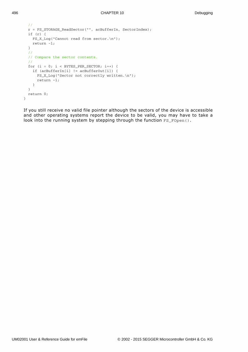
496 CHAPTER 10 Debugging
// r = FS_STORAGE_ReadSector("", acBufferIn, SectorIndex); if (r) { FS_X_Log("Cannot read from sector.\n"); return -1; } // // Compare the sector contents. // for (i = 0; i < BYTES_PER_SECTOR; i++) { if (acBufferIn[i] != acBufferOut[i]) { FS_X_Log("Sector not correctly written.\n"); return -1; } } return 0;}
If you still receive no valid file pointer although the sectors of the device is accessibleand other operating systems report the device to be valid, you may have to take alook into the running system by stepping through the function FS_FOpen().
UM02001 User & Reference Guide for emFile © 2002 - 2015 SEGGER Microcontroller GmbH & Co. KG
497
Chapter 11
Performance and resource usage
UM02001 User & Reference Guide for emFile © 2002 - 2015 SEGGER Microcontroller GmbH & Co. KG
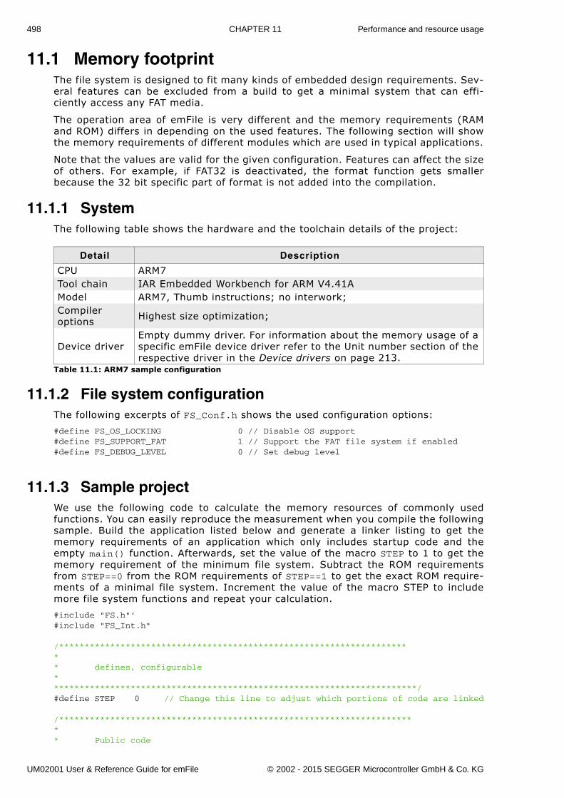
498 CHAPTER 11 Performance and resource usage
11.1 Memory footprintThe file system is designed to fit many kinds of embedded design requirements. Sev-eral features can be excluded from a build to get a minimal system that can effi-ciently access any FAT media.
The operation area of emFile is very different and the memory requirements (RAMand ROM) differs in depending on the used features. The following section will showthe memory requirements of different modules which are used in typical applications.
Note that the values are valid for the given configuration. Features can affect the sizeof others. For example, if FAT32 is deactivated, the format function gets smallerbecause the 32 bit specific part of format is not added into the compilation.
11.1.1 SystemThe following table shows the hardware and the toolchain details of the project:
11.1.2 File system configurationThe following excerpts of FS_Conf.h shows the used configuration options:
#define FS_OS_LOCKING 0 // Disable OS support#define FS_SUPPORT_FAT 1 // Support the FAT file system if enabled#define FS_DEBUG_LEVEL 0 // Set debug level
11.1.3 Sample projectWe use the following code to calculate the memory resources of commonly usedfunctions. You can easily reproduce the measurement when you compile the followingsample. Build the application listed below and generate a linker listing to get thememory requirements of an application which only includes startup code and theempty main() function. Afterwards, set the value of the macro STEP to 1 to get thememory requirement of the minimum file system. Subtract the ROM requirementsfrom STEP==0 from the ROM requirements of STEP==1 to get the exact ROM require-ments of a minimal file system. Increment the value of the macro STEP to includemore file system functions and repeat your calculation.
#include "FS.h"’#include "FS_Int.h"
/********************************************************************** defines, configurable************************************************************************/#define STEP 0 // Change this line to adjust which portions of code are linked
/*********************************************************************** Public code
Detail Description
CPU ARM7Tool chain IAR Embedded Workbench for ARM V4.41AModel ARM7, Thumb instructions; no interwork;Compiler options Highest size optimization;
Device driverEmpty dummy driver. For information about the memory usage of a specific emFile device driver refer to the Unit number section of the respective driver in the Device drivers on page 213.
Table 11.1: ARM7 sample configuration
UM02001 User & Reference Guide for emFile © 2002 - 2015 SEGGER Microcontroller GmbH & Co. KG
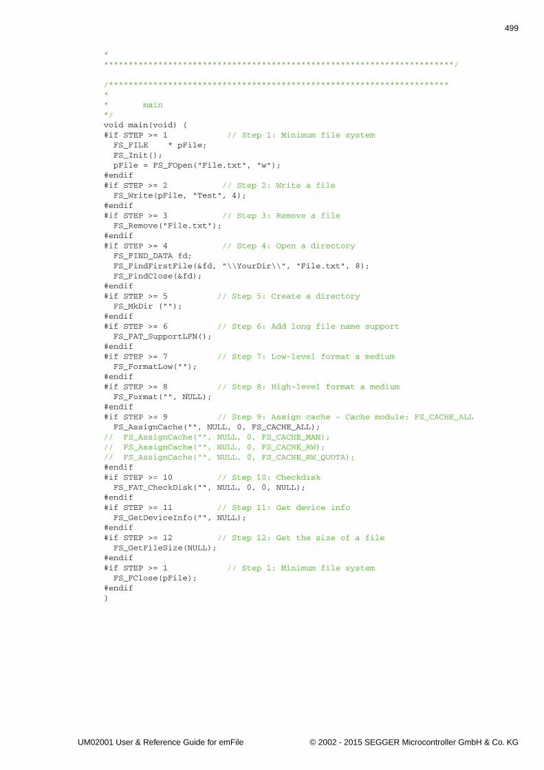
499
************************************************************************/
/*********************************************************************** main*/void main(void) {#if STEP >= 1 // Step 1: Minimum file system FS_FILE * pFile; FS_Init(); pFile = FS_FOpen("File.txt", "w");#endif#if STEP >= 2 // Step 2: Write a file FS_Write(pFile, "Test", 4);#endif#if STEP >= 3 // Step 3: Remove a file FS_Remove("File.txt");#endif#if STEP >= 4 // Step 4: Open a directory FS_FIND_DATA fd; FS_FindFirstFile(&fd, "\\YourDir\\", "File.txt", 8); FS_FindClose(&fd);#endif#if STEP >= 5 // Step 5: Create a directory FS_MkDir ("");#endif#if STEP >= 6 // Step 6: Add long file name support FS_FAT_SupportLFN();#endif#if STEP >= 7 // Step 7: Low-level format a medium FS_FormatLow("");#endif#if STEP >= 8 // Step 8: High-level format a medium FS_Format("", NULL);#endif#if STEP >= 9 // Step 9: Assign cache - Cache module: FS_CACHE_ALL FS_AssignCache("", NULL, 0, FS_CACHE_ALL);// FS_AssignCache("", NULL, 0, FS_CACHE_MAN);// FS_AssignCache("", NULL, 0, FS_CACHE_RW);// FS_AssignCache("", NULL, 0, FS_CACHE_RW_QUOTA);#endif#if STEP >= 10 // Step 10: Checkdisk FS_FAT_CheckDisk("", NULL, 0, 0, NULL);#endif#if STEP >= 11 // Step 11: Get device info FS_GetDeviceInfo("", NULL);#endif#if STEP >= 12 // Step 12: Get the size of a file FS_GetFileSize(NULL);#endif#if STEP >= 1 // Step 1: Minimum file system FS_FClose(pFile);#endif}
UM02001 User & Reference Guide for emFile © 2002 - 2015 SEGGER Microcontroller GmbH & Co. KG
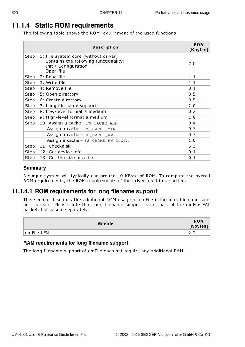
500 CHAPTER 11 Performance and resource usage
11.1.4 Static ROM requirementsThe following table shows the ROM requirement of the used functions:
Summary
A simple system will typically use around 10 KByte of ROM. To compute the overallROM requirements, the ROM requirements of the driver need to be added.
11.1.4.1 ROM requirements for long filename supportThis section describes the additional ROM usage of emFile if the long filename sup-port is used. Please note that long filename support is not part of the emFile FATpacket, but is sold separately.
RAM requirements for long filename support
The long filename support of emFile does not require any additional RAM.
DescriptionROM
[Kbytes]
Step 1: File system core (without driver) Contains the following functionality: Init / Configuration Open file
7.0
Step 2: Read file 1.1Step 3: Write file 1.1Step 4: Remove file 0.1Step 5: Open directory 0.5Step 6: Create directory 0.5Step 7: Long file name support 2.0Step 8: Low-level format a medium 0.2Step 9: High-level format a medium 1.8Step 10: Assign a cache - FS_CACHE_ALL 0.4 Assign a cache - FS_CACHE_MAN 0.7 Assign a cache - FS_CACHE_RW 0.7 Assign a cache - FS_CACHE_RW_QUOTA 1.0Step 11: Checkdisk 3.3Step 12: Get device info 0.1Step 13: Get the size of a file 0.1
ModuleROM
[Kbytes]
emFile LFN 2.2
UM02001 User & Reference Guide for emFile © 2002 - 2015 SEGGER Microcontroller GmbH & Co. KG
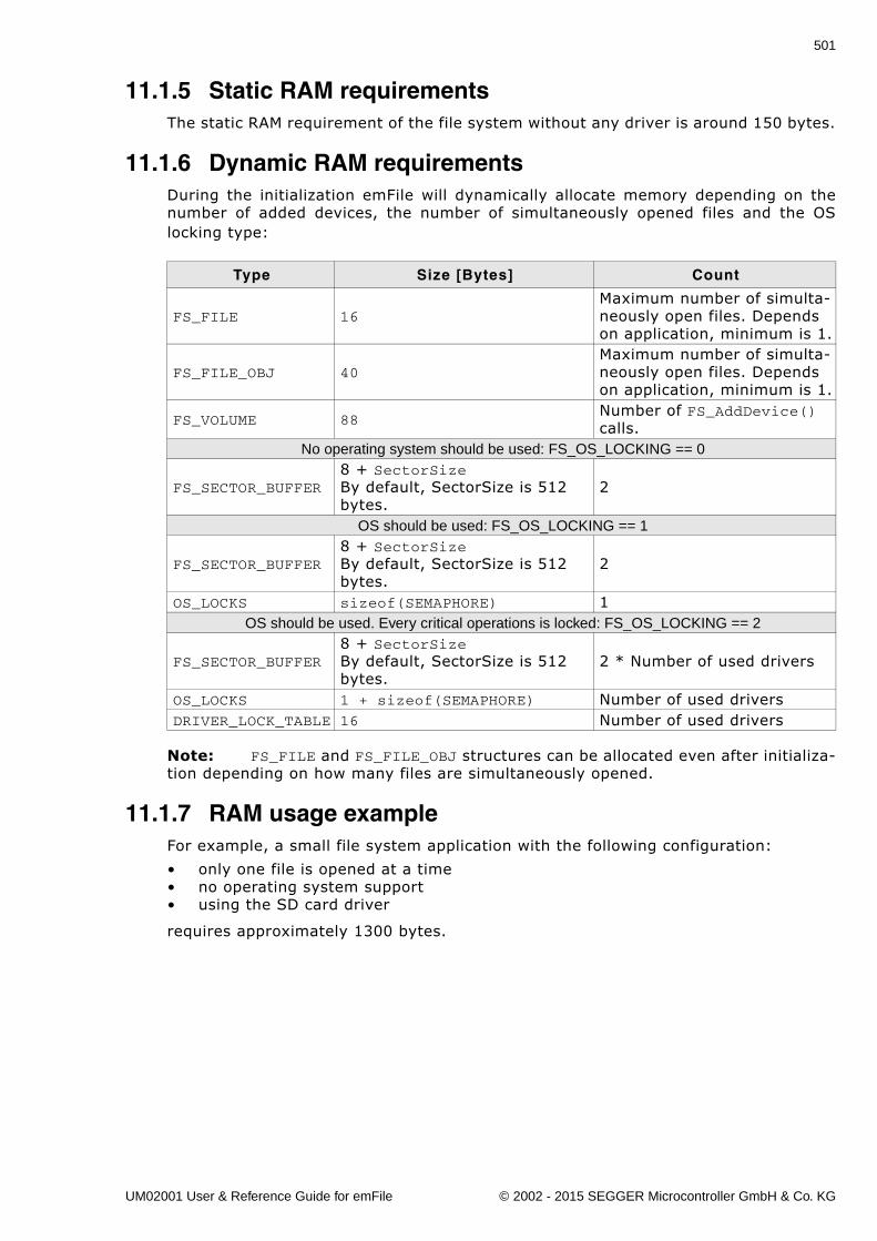
501
11.1.5 Static RAM requirementsThe static RAM requirement of the file system without any driver is around 150 bytes.
11.1.6 Dynamic RAM requirementsDuring the initialization emFile will dynamically allocate memory depending on thenumber of added devices, the number of simultaneously opened files and the OSlocking type:
Note: FS_FILE and FS_FILE_OBJ structures can be allocated even after initializa-tion depending on how many files are simultaneously opened.
11.1.7 RAM usage exampleFor example, a small file system application with the following configuration:
� only one file is opened at a time� no operating system support� using the SD card driver
requires approximately 1300 bytes.
Type Size [Bytes] Count
FS_FILE 16Maximum number of simulta-neously open files. Depends on application, minimum is 1.
FS_FILE_OBJ 40Maximum number of simulta-neously open files. Depends on application, minimum is 1.
FS_VOLUME 88Number of FS_AddDevice() calls.
No operating system should be used: FS_OS_LOCKING == 0
FS_SECTOR_BUFFER8 + SectorSizeBy default, SectorSize is 512 bytes.
2
OS should be used: FS_OS_LOCKING == 1
FS_SECTOR_BUFFER8 + SectorSizeBy default, SectorSize is 512 bytes.
2
OS_LOCKS sizeof(SEMAPHORE) 1OS should be used. Every critical operations is locked: FS_OS_LOCKING == 2
FS_SECTOR_BUFFER8 + SectorSizeBy default, SectorSize is 512 bytes.
2 * Number of used drivers
OS_LOCKS 1 + sizeof(SEMAPHORE) Number of used driversDRIVER_LOCK_TABLE 16 Number of used drivers
UM02001 User & Reference Guide for emFile © 2002 - 2015 SEGGER Microcontroller GmbH & Co. KG
502 CHAPTER 11 Performance and resource usage
11.2 PerformanceA benchmark is used to measure the speed of the software on available targets. Thisbenchmark is in no way complete, but it gives an approximation of the length of timerequired for common operations on various targets. You can find the measurementresults in the chapter describing the individual drivers.
11.2.1 Description of the performance testsThe performance tests are executed as described and in the order below.Performance test procedure:
1. Format the drive.2. Create and open a file for writing.
W: Start measuring of write performance.3. Write a multiple of 8 Kbytes.
W: Stop measuring of write performance.4. Close the file5. Reopen the file.
R: Start measuring of read performance.6. Read a multiple of 8 Kbytes.
R: Stop measuring of read performance.7. Close the file8. Show the performance results.
The performance tests can be reproduced. Include FS_PerformanceSimple.c(located in the folder .\Sample\API) into your project. Compile and run the projecton your target hardware.
11.2.2 How to improve the performanceIf you find that the performance of emFile on your hardware is not what you expectthere are several ways you can improve it.
Use the proper write mode
The default behavior of the file system is to update the allocation table and the direc-tory entry after each write operation. If several write operations are performedbetween the opening and the closing of the file it is recommended to set the writemode to FS_WRITEMODE_MEDIUM or FS_WRITEMODE_FAST to increase the performance.In these modes the allocation table and the directory entry are updated only whenthe file is closed. Refer to FS_SetFileWriteMode() on page 68 to learn how the writemode can be configured. Please note that these write modes can not be used whenthe journaling is enabled.
Write multiple of sector size
The file system implements a 0-copy mechanism in which the data written to a fileusing the FS_FWrite() and FS_Write() functions is passed directly to the device driverif the data is written at a sector boundary and the number of bytes written is a mul-tiple of sector size. In any other case the file system uses a read-modify-write oper-ation which increases the number of I/O operations and reduces the performance.The file system makes sure that the contents of a file always begins at a sectorboundary.
Use the file buffer
It is recommended to activate the file buffering when the application reads andwrites amounts of data smaller than the sector size. Refer toFS_ConfigFileBufferDefault() on page 62 to see how this can be done. The file bufferis a small cache which helps reducing the number of times storage medium isaccessed and thus increasing the performance. Please note that a file buffer in writemode can not be used when the journaling is enabled.
UM02001 User & Reference Guide for emFile © 2002 - 2015 SEGGER Microcontroller GmbH & Co. KG
503
Use a sector cache
The sector cache can be enabled to increase the overall performance of the file sys-tem. For more information refer to Optimizing performance - Caching and bufferingon page 197.
Configure a read-ahead driver
The read-ahead driver is useful when a storage medium is used which is more effi-cient when several sectors are read or written at once. This includes storage mediasuch as CompactFlash cards, SD and MMC cards and USB sticks. Normally, the filesystem reads the allocation table one sector at a time. If configured, the file systemactivates the read-ahead driver at run time when the allocation table is accessedreducing, for example, the time it takes to determine the amount of free space. Formore information refer to Sector read-ahead driver on page 459.
Optimize the hardware layer
Ensure that the routines of the hardware layer are fast. How you do that depends onyour compiler. Some compilers have the option to define a function as running fromRAM which is faster compared to running it from flash.
Use the FS_OPTIMIZE macro
The definitions of time critical functions in emFile are prefixed with the macroFS_OPTIMIZE. As default it expands to nothing. You can use this macro to enable thecompiler optimization only for these functions. How you define this macro dependson your compiler.
UM02001 User & Reference Guide for emFile © 2002 - 2015 SEGGER Microcontroller GmbH & Co. KG
504 CHAPTER 11 Performance and resource usage
UM02001 User & Reference Guide for emFile © 2002 - 2015 SEGGER Microcontroller GmbH & Co. KG
505
Chapter 12
Journaling (Add-on)
This chapter documents and explains emFile�s journaling add-on. Journaling is anextension to emFile that makes the file system layer fail-safe.
UM02001 User & Reference Guide for emFile © 2002 - 2015 SEGGER Microcontroller GmbH & Co. KG
506 CHAPTER 12 Journaling (Add-on)
12.1 IntroductionemFile Journaling is an additional component which sits on top of the file system andmakes the file system layer fail-safe. File systems without journaling support (forexample, FAT) are not fail-safe. Journaling means that a file system logs all changesto a journal before committing them to the main file system.
Driver fail-safety
Data can be lost in case of unexpected Reset in either the file system Layer (FAT orEFS) or in the driver layer. The entire system is fail-safe only if BOTH layers are fail-safe. The journaling add-on makes only the file system layer fail-safe. For fail-safetyof the driver layer, refer to Device drivers on page 213.
UM02001 User & Reference Guide for emFile © 2002 - 2015 SEGGER Microcontroller GmbH & Co. KG
507
12.2 Features� Non fail-safe file systems will be fail-safe.� Fully compatible to standard file system implementations (e.g. FAT)� Every storage solution can be used.
No reformat required.� Multiple write accesses to the storage medium can be combined in user applica-
tion.
UM02001 User & Reference Guide for emFile © 2002 - 2015 SEGGER Microcontroller GmbH & Co. KG
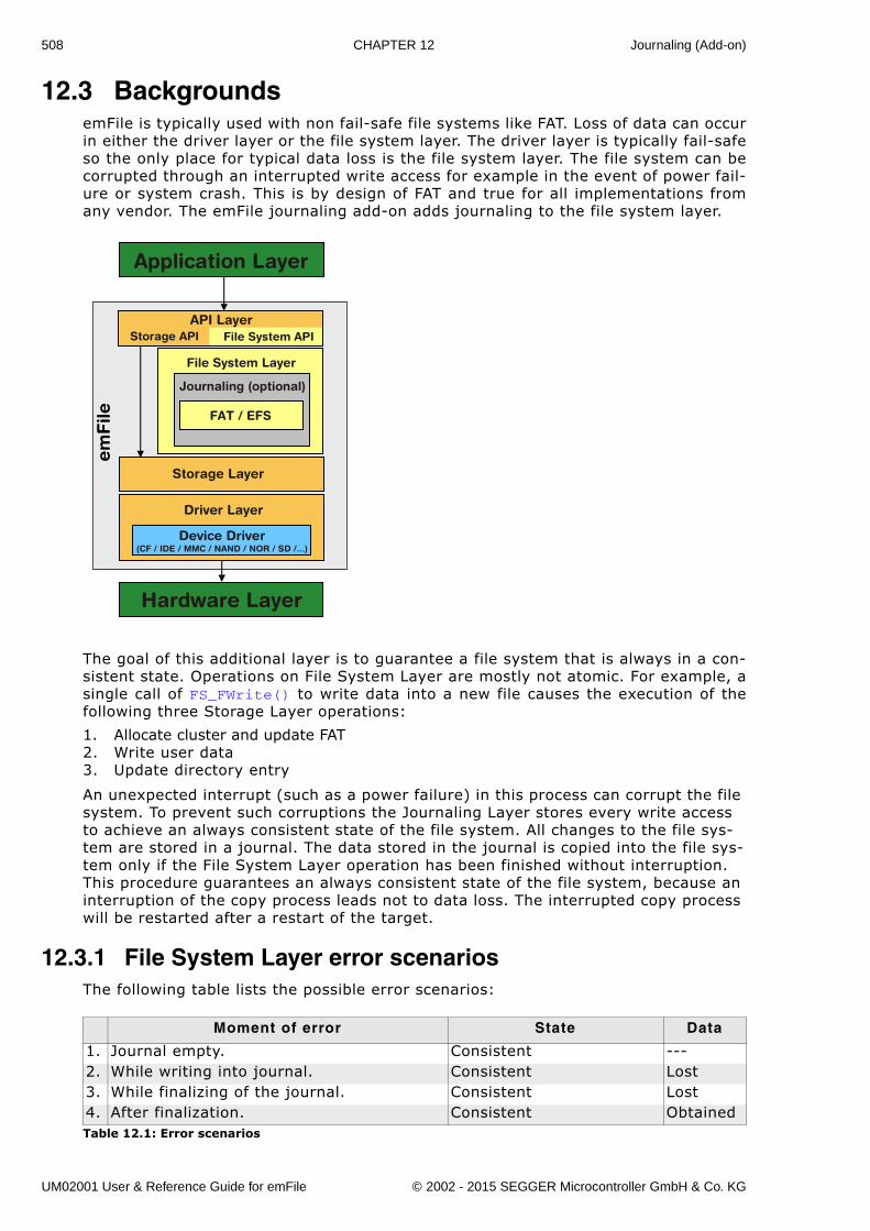
508 CHAPTER 12 Journaling (Add-on)
12.3 BackgroundsemFile is typically used with non fail-safe file systems like FAT. Loss of data can occurin either the driver layer or the file system layer. The driver layer is typically fail-safeso the only place for typical data loss is the file system layer. The file system can becorrupted through an interrupted write access for example in the event of power fail-ure or system crash. This is by design of FAT and true for all implementations fromany vendor. The emFile journaling add-on adds journaling to the file system layer.
The goal of this additional layer is to guarantee a file system that is always in a con-sistent state. Operations on File System Layer are mostly not atomic. For example, asingle call of FS_FWrite() to write data into a new file causes the execution of thefollowing three Storage Layer operations:
1. Allocate cluster and update FAT2. Write user data3. Update directory entry
An unexpected interrupt (such as a power failure) in this process can corrupt the file system. To prevent such corruptions the Journaling Layer stores every write access to achieve an always consistent state of the file system. All changes to the file sys-tem are stored in a journal. The data stored in the journal is copied into the file sys-tem only if the File System Layer operation has been finished without interruption. This procedure guarantees an always consistent state of the file system, because an interruption of the copy process leads not to data loss. The interrupted copy process will be restarted after a restart of the target.
12.3.1 File System Layer error scenariosThe following table lists the possible error scenarios:
Moment of error State Data
1. Journal empty. Consistent ---2. While writing into journal. Consistent Lost3. While finalizing of the journal. Consistent Lost4. After finalization. Consistent ObtainedTable 12.1: Error scenarios
File System Layer
Storage Layer
Application Layer
Hardware Layer
em
File
File System APIStorage APIAPI Layer
Device Driver(CF / IDE / MMC / NAND / NOR / SD /...)
Driver Layer
Journaling (optional)
FAT / EFS
UM02001 User & Reference Guide for emFile © 2002 - 2015 SEGGER Microcontroller GmbH & Co. KG
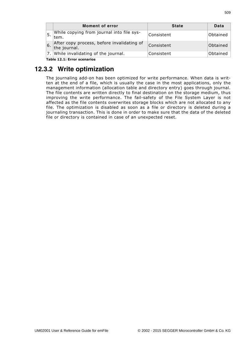
509
12.3.2 Write optimizationThe journaling add-on has been optimized for write performance. When data is writ-ten at the end of a file, which is usually the case in the most applications, only themanagement information (allocation table and directory entry) goes through journal.The file contents are written directly to final destination on the storage medium, thusimproving the write performance. The fail-safety of the File System Layer is notaffected as the file contents overwrites storage blocks which are not allocated to anyfile. The optimization is disabled as soon as a file or directory is deleted during ajournaling transaction. This is done in order to make sure that the data of the deletedfile or directory is contained in case of an unexpected reset.
5. While copying from journal into file sys-tem. Consistent Obtained
6. After copy process, before invalidating of the journal. Consistent Obtained
7. While invalidating of the journal. Consistent Obtained
Moment of error State Data
Table 12.1: Error scenarios
UM02001 User & Reference Guide for emFile © 2002 - 2015 SEGGER Microcontroller GmbH & Co. KG
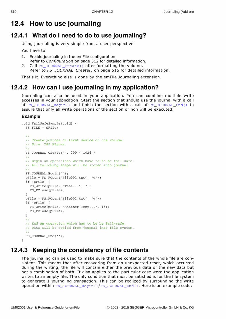
510 CHAPTER 12 Journaling (Add-on)
12.4 How to use journaling
12.4.1 What do I need to do to use journaling?Using journaling is very simple from a user perspective.
You have to
1. Enable journaling in the emFile configuration.Refer to Configuration on page 512 for detailed information.
2. Call FS_JOURNAL_Create() after formatting the volume.Refer to FS_JOURNAL_Create() on page 515 for detailed information.
That's it. Everything else is done by the emFile Journaling extension.
12.4.2 How can I use journaling in my application?Journaling can also be used in your application. You can combine multiple writeaccesses in your application. Start the section that should use the journal with a callof FS_JOURNAL_Begin() and finish the section with a call of FS_JOURNAL_End() toassure that only all write operations of the section or non will be executed.
Examplevoid FailSafeSample(void) { FS_FILE * pFile;
// // Create journal on first device of the volume. // Size: 200 KBytes. // FS_JOURNAL_Create("", 200 * 1024); // // Begin an operations which have to be be fail-safe. // All following steps will be stored into journal. // FS_JOURNAL_Begin(""); pFile = FS_FOpen(“File001.txt”, "w"); if (pFile) { FS_Write(pFile, "Test...", 7); FS_FClose(pFile); } pFile = FS_FOpen(“File002.txt”, "w"); if (pFile) { FS_Write(pFile, "Another Test...", 15); FS_FClose(pFile); } // // End an operation which has to be be fail-safe. // Data will be copied from journal into file system. // FS_JOURNAL_End("");}
12.4.3 Keeping the consistency of file contentsThe journaling can be used to make sure that the contents of the whole file are con-sistent. This means that after recovering from an unexpected reset, which occurredduring the writing, the file will contain either the previous data or the new data butnot a combination of both. It also applies to the particular case were the applicationwrites to an empty file. The only condition that must be satisfied is for the file systemto generate 1 journaling transaction. This can be realized by surrounding the writeoperation within FS_JOURNAL_Begin()/FS_JOURNAL_End(). Here is an example code:
UM02001 User & Reference Guide for emFile © 2002 - 2015 SEGGER Microcontroller GmbH & Co. KG
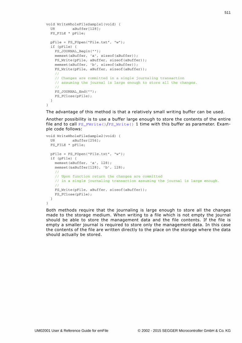
511
void WriteWholeFileSample1(void) { U8 aBuffer[128]; FS_FILE * pFile;
pFile = FS_FOpen(“File.txt”, "w"); if (pFile) { FS_JOURNAL_Begin(""); memset(aBuffer, ’a’, sizeof(aBuffer)); FS_Write(pFile, aBuffer, sizeof(aBuffer)); memset(aBuffer, ’b’, sizeof(aBuffer)); FS_Write(pFile, aBuffer, sizeof(aBuffer)); // // Changes are committed in a single journaling transaction // assuming the journal is large enough to store all the changes. // FS_JOURNAL_End(""); FS_FClose(pFile); }}
The advantage of this method is that a relatively small writing buffer can be used.
Another possibility is to use a buffer large enough to store the contents of the entirefile and to call FS_FWrite()/FS_Write() 1 time with this buffer as parameter. Exam-ple code follows:
void WriteWholeFileSample2(void) { U8 aBuffer[256]; FS_FILE * pFile;
pFile = FS_FOpen(“File.txt”, "w"); if (pFile) { memset(aBuffer, ’a’, 128); memset(&aBuffer[128], ’b’, 128); // // Upon function return the changes are committed // in a single journaling transaction assuming the journal is large enough. // FS_Write(pFile, aBuffer, sizeof(aBuffer)); FS_FClose(pFile); }}
Both methods require that the journaling is large enough to store all the changesmade to the storage medium. When writing to a file which is not empty the journalshould be able to store the management data and the file contents. If the file isempty a smaller journal is required to store only the management data. In this casethe contents of the file are written directly to the place on the storage where the datashould actually be stored.
UM02001 User & Reference Guide for emFile © 2002 - 2015 SEGGER Microcontroller GmbH & Co. KG
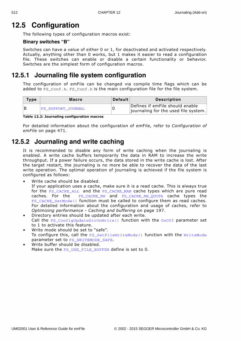
512 CHAPTER 12 Journaling (Add-on)
12.5 ConfigurationThe following types of configuration macros exist:
Binary switches “B”
Switches can have a value of either 0 or 1, for deactivated and activated respectively.Actually, anything other than 0 works, but 1 makes it easier to read a configurationfile. These switches can enable or disable a certain functionality or behavior.Switches are the simplest form of configuration macros.
12.5.1 Journaling file system configurationThe configuration of emFile can be changed via compile time flags which can beadded to FS_Conf.h. FS_Conf.h is the main configuration file for the file system.
For detailed information about the configuration of emFile, refer to Configuration ofemFile on page 471.
12.5.2 Journaling and write cachingIt is recommended to disable any form of write caching when the journaling isenabled. A write cache buffers temporarily the data in RAM to increase the writethroughput. If a power failure occurs, the data stored in the write cache is lost. Afterthe target restart, the journaling is no more be able to recover the data of the lastwrite operation. The optimal operation of journaling is achieved if the file system isconfigured as follows:
� Write cache should be disabled.If your application uses a cache, make sure it is a read cache. This is always truefor the FS_CACHE_ALL and the FS_CACHE_MAN cache types which are pure readcaches. For the FS_CACHE_RW and FS_CACHE_RW_QUOTA cache types theFS_CACHE_SetMode() function must be called to configure them as read caches.For detailed information about the configuration and usage of caches, refer toOptimizing performance - Caching and buffering on page 197.
� Directory entries should be updated after each write. Call the FS_ConfigUpdateDirOnWrite() function with the OnOff parameter setto 1 to activate this feature.
� Write mode should be set to �safe�.To configure this, call the FS_SetFileWriteMode() function with the WriteModeparameter set to FS_WRITEMODE_SAFE.
� Write buffer should be disabled.Make sure the FS_USE_FILE_BUFFER define is set to 0.
Type Macro Default Description
B FS_SUPPORT_JOURNAL 0 Defines if emFile should enable journaling for the used file system.
Table 12.2: Journaling configuration macros
UM02001 User & Reference Guide for emFile © 2002 - 2015 SEGGER Microcontroller GmbH & Co. KG
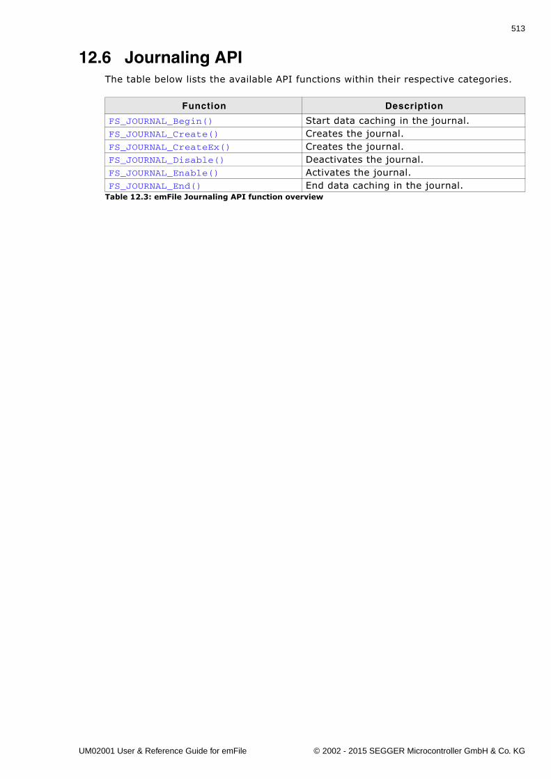
513
12.6 Journaling APIThe table below lists the available API functions within their respective categories.
Function Description
FS_JOURNAL_Begin() Start data caching in the journal.FS_JOURNAL_Create() Creates the journal.FS_JOURNAL_CreateEx() Creates the journal.FS_JOURNAL_Disable() Deactivates the journal.FS_JOURNAL_Enable() Activates the journal.FS_JOURNAL_End() End data caching in the journal.
Table 12.3: emFile Journaling API function overview
UM02001 User & Reference Guide for emFile © 2002 - 2015 SEGGER Microcontroller GmbH & Co. KG
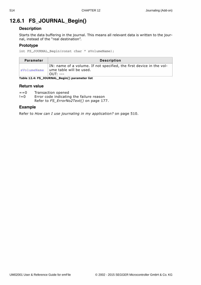
514 CHAPTER 12 Journaling (Add-on)
12.6.1 FS_JOURNAL_Begin()Description
Starts the data buffering in the journal. This means all relevant data is written to the jour-nal, instead of the �real destination�.
Prototypeint FS_JOURNAL_Begin(const char * sVolumeName);
Return value
==0 Transaction opened!=0 Error code indicating the failure reason
Refer to FS_ErrorNo2Text() on page 177.
Example
Refer to How can I use journaling in my application? on page 510.
Parameter Description
sVolumeNameIN: name of a volume. If not specified, the first device in the vol-ume table will be used.OUT: ---
Table 12.4: FS_JOURNAL_Begin() parameter list
UM02001 User & Reference Guide for emFile © 2002 - 2015 SEGGER Microcontroller GmbH & Co. KG
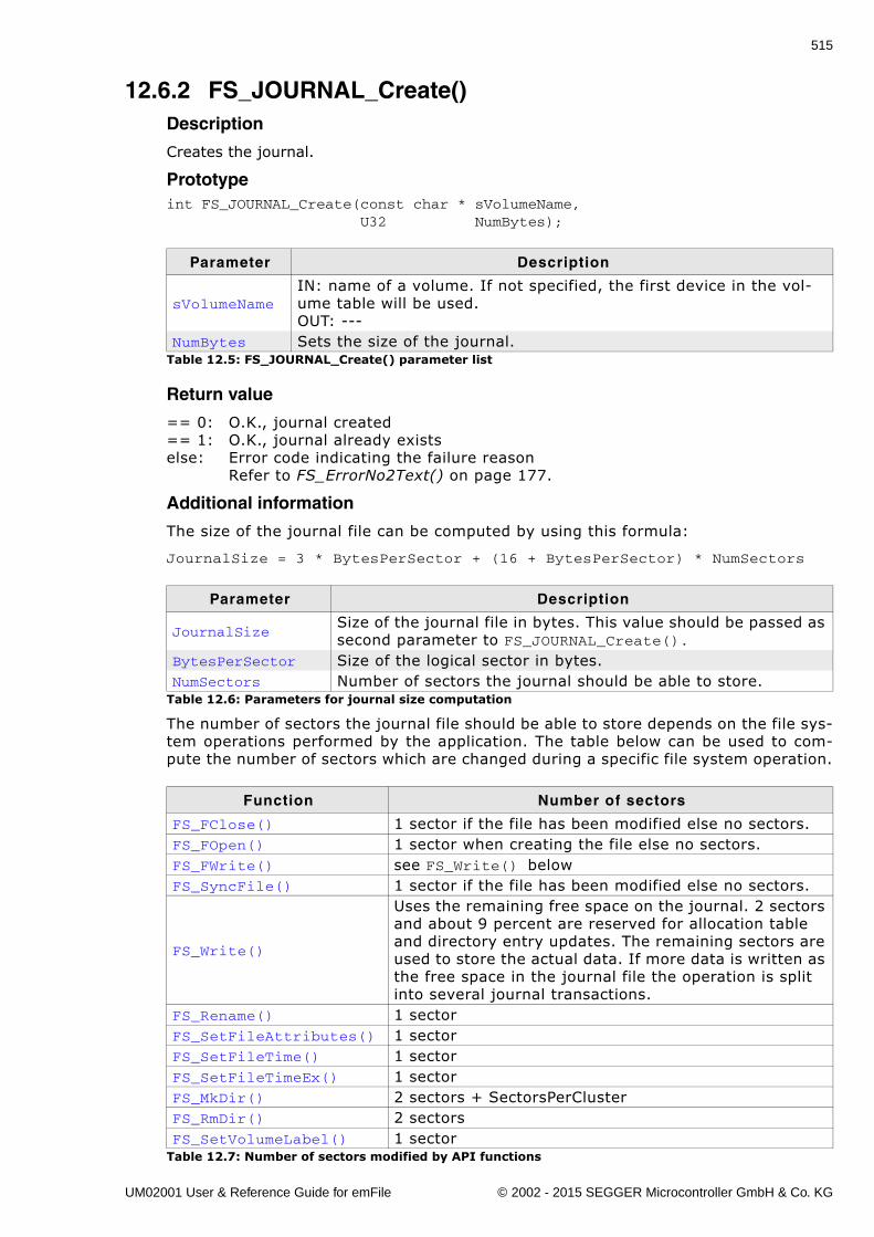
515
12.6.2 FS_JOURNAL_Create()Description
Creates the journal.
Prototypeint FS_JOURNAL_Create(const char * sVolumeName, U32 NumBytes);
Return value
== 0: O.K., journal created== 1: O.K., journal already existselse: Error code indicating the failure reason
Refer to FS_ErrorNo2Text() on page 177.
Additional information
The size of the journal file can be computed by using this formula:
JournalSize = 3 * BytesPerSector + (16 + BytesPerSector) * NumSectors
The number of sectors the journal file should be able to store depends on the file sys-tem operations performed by the application. The table below can be used to com-pute the number of sectors which are changed during a specific file system operation.
Parameter Description
sVolumeNameIN: name of a volume. If not specified, the first device in the vol-ume table will be used.OUT: ---
NumBytes Sets the size of the journal.Table 12.5: FS_JOURNAL_Create() parameter list
Parameter Description
JournalSizeSize of the journal file in bytes. This value should be passed as second parameter to FS_JOURNAL_Create().
BytesPerSector Size of the logical sector in bytes.NumSectors Number of sectors the journal should be able to store.
Table 12.6: Parameters for journal size computation
Function Number of sectors
FS_FClose() 1 sector if the file has been modified else no sectors.FS_FOpen() 1 sector when creating the file else no sectors.FS_FWrite() see FS_Write() belowFS_SyncFile() 1 sector if the file has been modified else no sectors.
FS_Write()
Uses the remaining free space on the journal. 2 sectors and about 9 percent are reserved for allocation table and directory entry updates. The remaining sectors are used to store the actual data. If more data is written as the free space in the journal file the operation is split into several journal transactions.
FS_Rename() 1 sectorFS_SetFileAttributes() 1 sectorFS_SetFileTime() 1 sectorFS_SetFileTimeEx() 1 sectorFS_MkDir() 2 sectors + SectorsPerClusterFS_RmDir() 2 sectorsFS_SetVolumeLabel() 1 sector
Table 12.7: Number of sectors modified by API functions
UM02001 User & Reference Guide for emFile © 2002 - 2015 SEGGER Microcontroller GmbH & Co. KG
516 CHAPTER 12 Journaling (Add-on)
Example
Refer to How can I use journaling in my application? on page 510.
UM02001 User & Reference Guide for emFile © 2002 - 2015 SEGGER Microcontroller GmbH & Co. KG
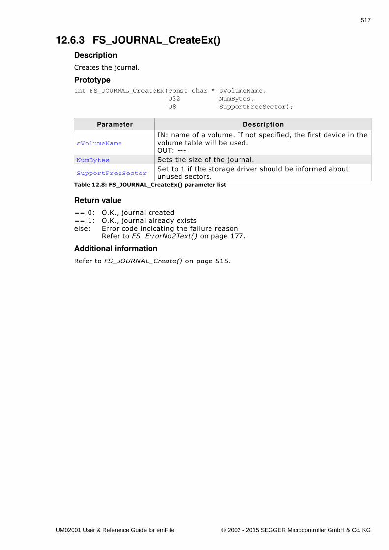
517
12.6.3 FS_JOURNAL_CreateEx()Description
Creates the journal.
Prototypeint FS_JOURNAL_CreateEx(const char * sVolumeName, U32 NumBytes, U8 SupportFreeSector);
Return value
== 0: O.K., journal created== 1: O.K., journal already existselse: Error code indicating the failure reason
Refer to FS_ErrorNo2Text() on page 177.
Additional information
Refer to FS_JOURNAL_Create() on page 515.
Parameter Description
sVolumeNameIN: name of a volume. If not specified, the first device in the volume table will be used.OUT: ---
NumBytes Sets the size of the journal.
SupportFreeSectorSet to 1 if the storage driver should be informed about unused sectors.
Table 12.8: FS_JOURNAL_CreateEx() parameter list
UM02001 User & Reference Guide for emFile © 2002 - 2015 SEGGER Microcontroller GmbH & Co. KG
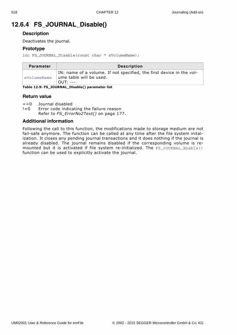
518 CHAPTER 12 Journaling (Add-on)
12.6.4 FS_JOURNAL_Disable()Description
Deactivates the journal.
Prototypeint FS_JOURNAL_Disable(const char * sVolumeName);
Return value
==0 Journal disabled!=0 Error code indicating the failure reason
Refer to FS_ErrorNo2Text() on page 177.
Additional information
Following the call to this function, the modifications made to storage medium are notfail-safe anymore. The function can be called at any time after the file system inital-ization. It closes any pending journal transactions and it does nothing if the journal isalready disabled. The journal remains disabled if the corresponding volume is re-mounted but it is activated if file system re-initialized. The FS_JOURNAL_Enable()function can be used to explicitly activate the journal.
Parameter Description
sVolumeNameIN: name of a volume. If not specified, the first device in the vol-ume table will be used.OUT: ---
Table 12.9: FS_JOURNAL_Disable() parameter list
UM02001 User & Reference Guide for emFile © 2002 - 2015 SEGGER Microcontroller GmbH & Co. KG
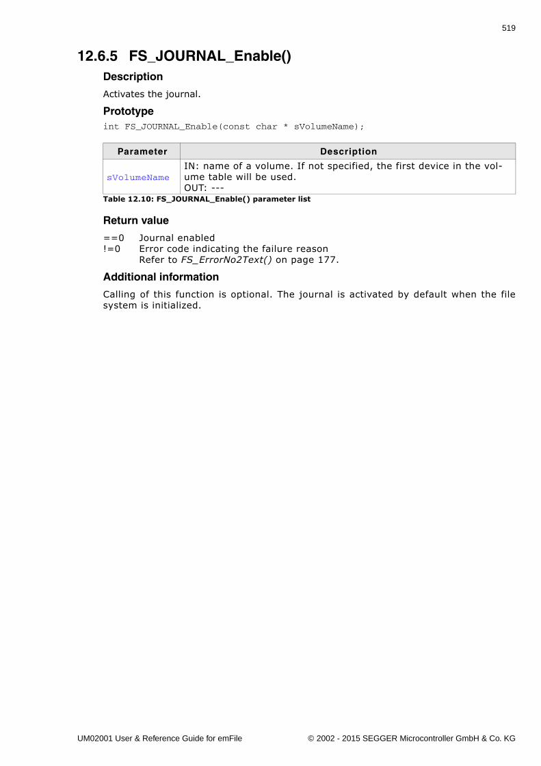
519
12.6.5 FS_JOURNAL_Enable()Description
Activates the journal.
Prototypeint FS_JOURNAL_Enable(const char * sVolumeName);
Return value
==0 Journal enabled!=0 Error code indicating the failure reason
Refer to FS_ErrorNo2Text() on page 177.
Additional information
Calling of this function is optional. The journal is activated by default when the filesystem is initialized.
Parameter Description
sVolumeNameIN: name of a volume. If not specified, the first device in the vol-ume table will be used.OUT: ---
Table 12.10: FS_JOURNAL_Enable() parameter list
UM02001 User & Reference Guide for emFile © 2002 - 2015 SEGGER Microcontroller GmbH & Co. KG
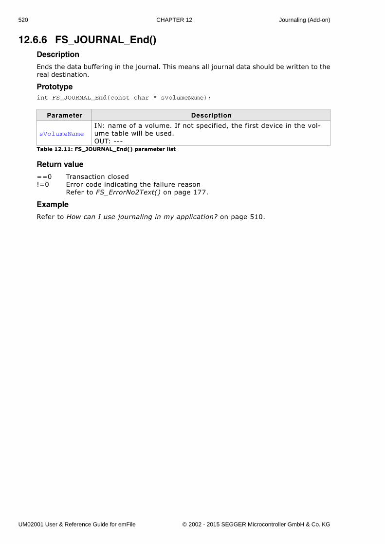
520 CHAPTER 12 Journaling (Add-on)
12.6.6 FS_JOURNAL_End()Description
Ends the data buffering in the journal. This means all journal data should be written to thereal destination.
Prototypeint FS_JOURNAL_End(const char * sVolumeName);
Return value
==0 Transaction closed!=0 Error code indicating the failure reason
Refer to FS_ErrorNo2Text() on page 177.
Example
Refer to How can I use journaling in my application? on page 510.
Parameter Description
sVolumeNameIN: name of a volume. If not specified, the first device in the vol-ume table will be used.OUT: ---
Table 12.11: FS_JOURNAL_End() parameter list
UM02001 User & Reference Guide for emFile © 2002 - 2015 SEGGER Microcontroller GmbH & Co. KG
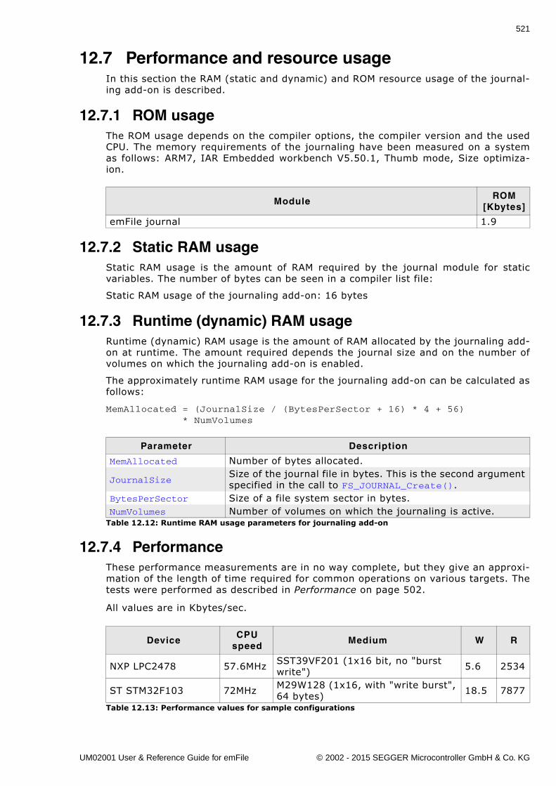
521
12.7 Performance and resource usageIn this section the RAM (static and dynamic) and ROM resource usage of the journal-ing add-on is described.
12.7.1 ROM usageThe ROM usage depends on the compiler options, the compiler version and the usedCPU. The memory requirements of the journaling have been measured on a systemas follows: ARM7, IAR Embedded workbench V5.50.1, Thumb mode, Size optimiza-ion.
12.7.2 Static RAM usageStatic RAM usage is the amount of RAM required by the journal module for staticvariables. The number of bytes can be seen in a compiler list file:
Static RAM usage of the journaling add-on: 16 bytes
12.7.3 Runtime (dynamic) RAM usageRuntime (dynamic) RAM usage is the amount of RAM allocated by the journaling add-on at runtime. The amount required depends the journal size and on the number ofvolumes on which the journaling add-on is enabled.
The approximately runtime RAM usage for the journaling add-on can be calculated asfollows:
MemAllocated = (JournalSize / (BytesPerSector + 16) * 4 + 56) * NumVolumes
12.7.4 PerformanceThese performance measurements are in no way complete, but they give an approxi-mation of the length of time required for common operations on various targets. Thetests were performed as described in Performance on page 502.
All values are in Kbytes/sec.
ModuleROM
[Kbytes]
emFile journal 1.9
Parameter Description
MemAllocated Number of bytes allocated.
JournalSizeSize of the journal file in bytes. This is the second argument specified in the call to FS_JOURNAL_Create().
BytesPerSector Size of a file system sector in bytes.NumVolumes Number of volumes on which the journaling is active.
Table 12.12: Runtime RAM usage parameters for journaling add-on
DeviceCPU
speedMedium W R
NXP LPC2478 57.6MHz SST39VF201 (1x16 bit, no "burst write") 5.6 2534
ST STM32F103 72MHz M29W128 (1x16, with "write burst", 64 bytes) 18.5 7877
Table 12.13: Performance values for sample configurations
UM02001 User & Reference Guide for emFile © 2002 - 2015 SEGGER Microcontroller GmbH & Co. KG
522 CHAPTER 12 Journaling (Add-on)
12.8 FAQsQ: Can a journal be created when other files are already present on the disk?A: Yes. The journal saves its data in a normal file called Journal.dat. If there is
enough space left on the medium there is no problem to create the journal even ifother files are present.
Q: Can a journal can be re-created?A: Yes. Follow this procedure to recreate the journal:
- remove Journal.dat file- unmount the file system- mount the file system- re-create the journal
Q: Can a journal be deleted?A: Yes, by deleting the Journal.dat file.
Q: What if the journal isn't big enough?A: If the journal is not big enough the data already stored on the journal is saved to
the real location on the medium and an error message is generated.
Q: Can multiple tasks use a journal at the same time?A: Yes, the journal is multitasking safe.
Q: Can FS_JOURNAL_Begin() and FS_JOURNAL_End() be nested?A: Yes. There is a reference counter that is incremented with each invocation of
FS_JOURNAL_Begin() and is decremented when FS_JOURNAL_End() is called.When the reference counter reaches zero the data is transferred from journal tothe real destination on the medium and the journal is cleared.
UM02001 User & Reference Guide for emFile © 2002 - 2015 SEGGER Microcontroller GmbH & Co. KG
523
Chapter 13
Encryption (Add-on)
This chapter documents and explains emFile�s encryption add-on. Encryption is anextension to emFile which allows for the data to be stored in a secure way.
UM02001 User & Reference Guide for emFile © 2002 - 2015 SEGGER Microcontroller GmbH & Co. KG
524 CHAPTER 13 Encryption (Add-on)
13.1 IntroductionemFile Encryption is an additional component which can be used to secure the dataof the entire volume or of individual files. Without encryption support all the data isstored in a readable form. Using the encryption the data can be made unreadablebefore being stored using a key. Without the knowledge of the key it is not possibleto make the data readable again.
UM02001 User & Reference Guide for emFile © 2002 - 2015 SEGGER Microcontroller GmbH & Co. KG
525
13.2 Features� Can be used with both FAT and EFS file systems.� All storage types such as NAND, NOR, SD/MMC/CompactFlash cards are sup-
ported.� Only minor changes of application are required.� DES and AES with 128-bit and 256-bit key lengths are supported.� Encryption of entire media or of individual files.� A tool available to decrypt/encrypt files on a PC.
UM02001 User & Reference Guide for emFile © 2002 - 2015 SEGGER Microcontroller GmbH & Co. KG
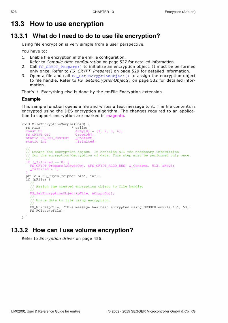
526 CHAPTER 13 Encryption (Add-on)
13.3 How to use encryption
13.3.1 What do I need to do to use file encryption?Using file encryption is very simple from a user perspective.
You have to:
1. Enable file encryption in the emFile configuration.Refer to Compile time configuration on page 527 for detailed information.
2. Call FS_CRYPT_Prepare() to initialize an encryption object. It must be performedonly once. Refer to FS_CRYPT_Prepare() on page 529 for detailed information.
3. Open a file and call FS_SetEncryptionObject() to assign the encryption objectto file handle. Refer to FS_SetEncryptionObject() on page 532 for detailed infor-mation.
That's it. Everything else is done by the emFile Encryption extension.
Example
This sample function opens a file and writes a text message to it. The file contents isencrypted using the DES encryption algorithm. The changes required to an applica-tion to support encryption are marked in magenta.
void FileEncryptionSample(void) { FS_FILE * pFile; const U8 aKey[8] = {1, 2, 3, 4}; FS_CRYPT_OBJ CryptObj; static FS_DES_CONTEXT _Context; static int _IsInited;
// // Create the encryption object. It contains all the necessary information // for the encryption/decryption of data. This step must be performed only once. // if (_IsInited == 0) { FS_CRYPT_Prepare(&CryptObj, &FS_CRYPT_ALGO_DES, &_Context, 512, aKey); _IsInited = 1; } pFile = FS_FOpen("cipher.bin", "w"); if (pFile) { // // Assign the created encryption object to file handle. // FS_SetEncryptionObject(pFile, &CryptObj); // // Write data to file using encryption. // FS_Write(pFile, "This message has been encrypted using SEGGER emFile.\n", 53); FS_FClose(pFile); }}
13.3.2 How can I use volume encryption?Refer to Encryption driver on page 456.
UM02001 User & Reference Guide for emFile © 2002 - 2015 SEGGER Microcontroller GmbH & Co. KG
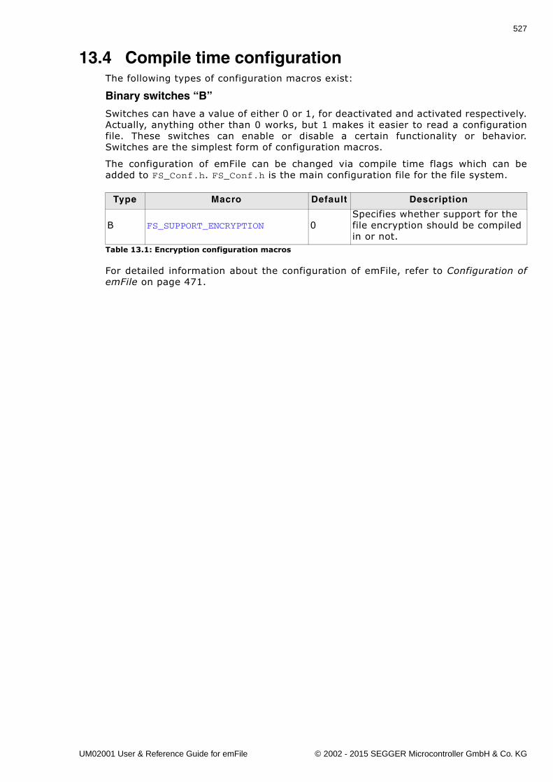
527
13.4 Compile time configurationThe following types of configuration macros exist:
Binary switches “B”
Switches can have a value of either 0 or 1, for deactivated and activated respectively.Actually, anything other than 0 works, but 1 makes it easier to read a configurationfile. These switches can enable or disable a certain functionality or behavior.Switches are the simplest form of configuration macros.
The configuration of emFile can be changed via compile time flags which can beadded to FS_Conf.h. FS_Conf.h is the main configuration file for the file system.
For detailed information about the configuration of emFile, refer to Configuration ofemFile on page 471.
Type Macro Default Description
B FS_SUPPORT_ENCRYPTION 0Specifies whether support for the file encryption should be compiled in or not.
Table 13.1: Encryption configuration macros
UM02001 User & Reference Guide for emFile © 2002 - 2015 SEGGER Microcontroller GmbH & Co. KG
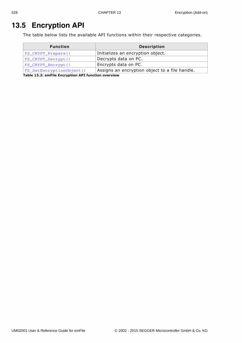
528 CHAPTER 13 Encryption (Add-on)
13.5 Encryption APIThe table below lists the available API functions within their respective categories.
Function Description
FS_CRYPT_Prepare() Initializes an encryption object.FS_CRYPT_Decrypt() Decrypts data on PC.FS_CRYPT_Encrypt() Encrypts data on PC.FS_SetEncryptionObject() Assigns an encryption object to a file handle.
Table 13.2: emFile Encryption API function overview
UM02001 User & Reference Guide for emFile © 2002 - 2015 SEGGER Microcontroller GmbH & Co. KG
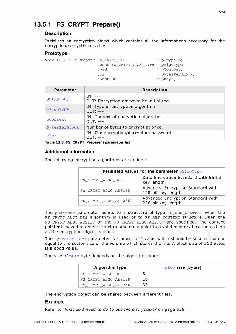
529
13.5.1 FS_CRYPT_Prepare()Description
Initializes an encryption object which contains all the informations necessary for theencryption/decryption of a file.
Prototypevoid FS_CRYPT_Prepare(FS_CRYPT_OBJ * pCryptObj, const FS_CRYPT_ALGO_TYPE * pAlgoType, void * pContext, U32 BytesPerBlock, const U8 * pKey);
Additional information
The following encryption algorithms are defined:
The pContext parameter points to a structure of type FS_DES_CONTEXT when theFS_CRYPT_ALGO_DES algorithm is used or to FS_AES_CONTEXT structure when theFS_CRYPT_ALGO_AES128 or the FS_CRYPT_ALGO_AES256 are specified. The contextpointer is saved to object structure and must point to a valid memory location as longas the encryption object is in use.
The BytesPerBlock parameter is a power of 2 value which should be smaller than orequal to the sector size of the volume which stores the file. A block size of 512 bytesis a good value.
The size of pKey byte depends on the algorithm type:
The encryption object can be shared between different files.
Example
Refer to What do I need to do to use file encryption? on page 526.
Parameter Description
pCryptObjIN: ---OUT: Encryption object to be initialized
pAlgoTypeIN: Type of encryption algorithmOUT: ---
pContextIN: Context of encryption algorithmOUT: ---
BytesPerBlock Number of bytes to encrypt at once.
pKeyIN: The encryption/decryption passwordOUT: ---
Table 13.3: FS_CRYPT_Prepare() parameter list
Permitted values for the parameter pAlgoType
FS_CRYPT_ALGO_DESData Encryption Standard with 56-bit key length
FS_CRYPT_ALGO_AES128Advanced Encryption Standard with 128-bit key length
FS_CRYPT_ALGO_AES256Advanced Encryption Standard with 256-bit key length
Algorithm type pKey size [bytes]
FS_CRYPT_ALGO_DES 8FS_CRYPT_ALGO_AES128 16FS_CRYPT_ALGO_AES256 32
UM02001 User & Reference Guide for emFile © 2002 - 2015 SEGGER Microcontroller GmbH & Co. KG
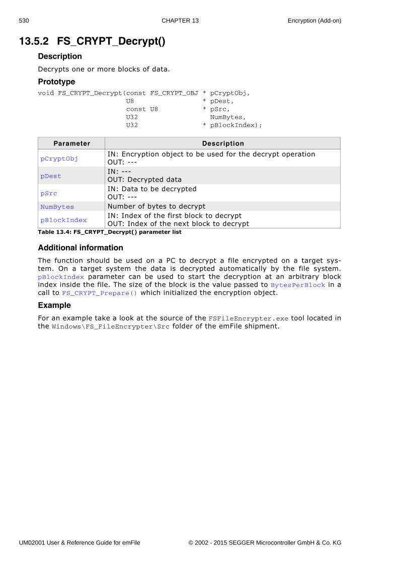
530 CHAPTER 13 Encryption (Add-on)
13.5.2 FS_CRYPT_Decrypt()Description
Decrypts one or more blocks of data.
Prototypevoid FS_CRYPT_Decrypt(const FS_CRYPT_OBJ * pCryptObj, U8 * pDest, const U8 * pSrc, U32 NumBytes, U32 * pBlockIndex);
Additional information
The function should be used on a PC to decrypt a file encrypted on a target sys-tem. On a target system the data is decrypted automatically by the file system.pBlockIndex parameter can be used to start the decryption at an arbitrary blockindex inside the file. The size of the block is the value passed to BytesPerBlock in acall to FS_CRYPT_Prepare() which initialized the encryption object.
Example
For an example take a look at the source of the FSFileEncrypter.exe tool located inthe Windows\FS_FileEncrypter\Src folder of the emFile shipment.
Parameter Description
pCryptObjIN: Encryption object to be used for the decrypt operationOUT: ---
pDestIN: ---OUT: Decrypted data
pSrcIN: Data to be decryptedOUT: ---
NumBytes Number of bytes to decrypt
pBlockIndexIN: Index of the first block to decryptOUT: Index of the next block to decrypt
Table 13.4: FS_CRYPT_Decrypt() parameter list
UM02001 User & Reference Guide for emFile © 2002 - 2015 SEGGER Microcontroller GmbH & Co. KG
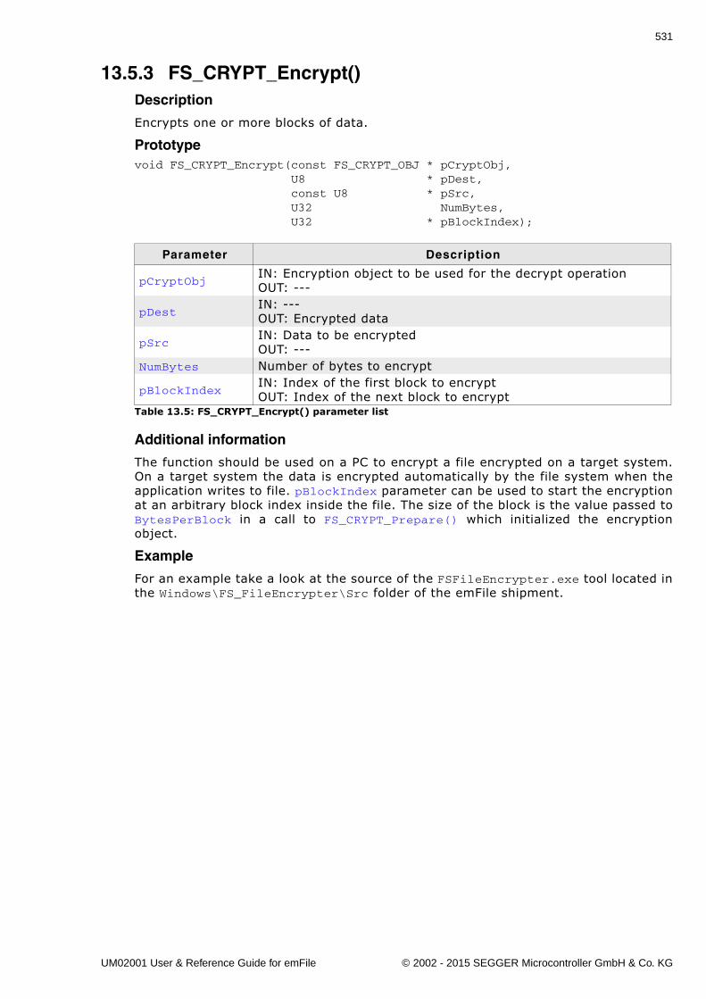
531
13.5.3 FS_CRYPT_Encrypt()Description
Encrypts one or more blocks of data.
Prototypevoid FS_CRYPT_Encrypt(const FS_CRYPT_OBJ * pCryptObj, U8 * pDest, const U8 * pSrc, U32 NumBytes, U32 * pBlockIndex);
Additional information
The function should be used on a PC to encrypt a file encrypted on a target system.On a target system the data is encrypted automatically by the file system when theapplication writes to file. pBlockIndex parameter can be used to start the encryptionat an arbitrary block index inside the file. The size of the block is the value passed toBytesPerBlock in a call to FS_CRYPT_Prepare() which initialized the encryptionobject.
Example
For an example take a look at the source of the FSFileEncrypter.exe tool located inthe Windows\FS_FileEncrypter\Src folder of the emFile shipment.
Parameter Description
pCryptObjIN: Encryption object to be used for the decrypt operationOUT: ---
pDestIN: ---OUT: Encrypted data
pSrcIN: Data to be encryptedOUT: ---
NumBytes Number of bytes to encrypt
pBlockIndexIN: Index of the first block to encryptOUT: Index of the next block to encrypt
Table 13.5: FS_CRYPT_Encrypt() parameter list
UM02001 User & Reference Guide for emFile © 2002 - 2015 SEGGER Microcontroller GmbH & Co. KG
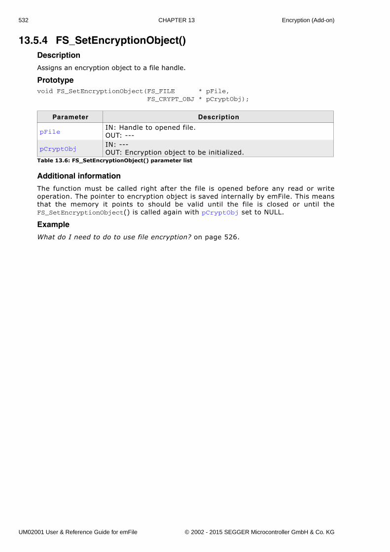
532 CHAPTER 13 Encryption (Add-on)
13.5.4 FS_SetEncryptionObject()Description
Assigns an encryption object to a file handle.
Prototypevoid FS_SetEncryptionObject(FS_FILE * pFile, FS_CRYPT_OBJ * pCryptObj);
Additional information
The function must be called right after the file is opened before any read or writeoperation. The pointer to encryption object is saved internally by emFile. This meansthat the memory it points to should be valid until the file is closed or until theFS_SetEncryptionObject() is called again with pCryptObj set to NULL.
Example
What do I need to do to use file encryption? on page 526.
Parameter Description
pFileIN: Handle to opened file.OUT: ---
pCryptObjIN: ---OUT: Encryption object to be initialized.
Table 13.6: FS_SetEncryptionObject() parameter list
UM02001 User & Reference Guide for emFile © 2002 - 2015 SEGGER Microcontroller GmbH & Co. KG
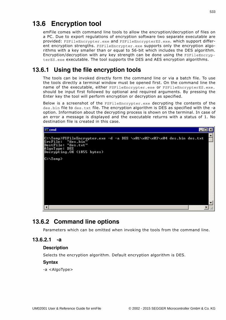
533
13.6 Encryption toolemFile comes with command line tools to allow the encryption/decryption of files ona PC. Due to export regulations of encryption software two separate executable areprovided: FSFileEncrypter.exe and FSFileEncrypterES.exe. which support differ-ent encryption strengths. FSFileEncrypter.exe supports only the encryption algo-rithms with a key smaller than or equal to 56-bit which includes the DES algorithm.Encryption/decryption with any key strength can be done using the FSFileEncryp-terES.exe executable. The tool supports the DES and AES encryption algorithms.
13.6.1 Using the file encryption toolsThe tools can be invoked directly form the command line or via a batch file. To usethe tools directly a terminal window must be opened first. On the command line thename of the executable, either FSFileEncrypter.exe or FSFileEncrypterES.exe,should be input first followed by optional and required arguments. By pressing theEnter key the tool will perform encryption or decryption as specified.
Below is a screenshot of the FSFileEncrypter.exe decrypting the contents of thedes.bin file to des.txt file. The encryption algorithm is DES as specified with the -aoption. Information about the decrypting process is shown on the terminal. In case ofan error a message is displayed and the executable returns with a status of 1. Nodestination file is created in this case.
13.6.2 Command line optionsParameters which can be omitted when invoking the tools from the command line.
13.6.2.1 -aDescription
Selects the encryption algorithm. Default encryption algorithm is DES.
Syntax
-a <AlgoType>
UM02001 User & Reference Guide for emFile © 2002 - 2015 SEGGER Microcontroller GmbH & Co. KG
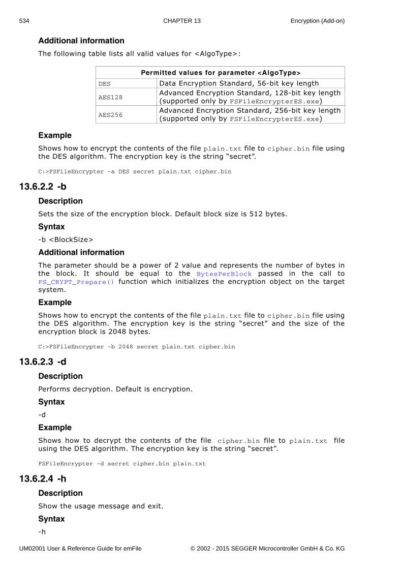
534 CHAPTER 13 Encryption (Add-on)
Additional information
The following table lists all valid values for <AlgoType>:
Example
Shows how to encrypt the contents of the file plain.txt file to cipher.bin file usingthe DES algorithm. The encryption key is the string �secret�.
C:>FSFileEncrypter -a DES secret plain.txt cipher.bin
13.6.2.2 -bDescription
Sets the size of the encryption block. Default block size is 512 bytes.
Syntax
-b <BlockSize>
Additional information
The parameter should be a power of 2 value and represents the number of bytes inthe block. It should be equal to the BytesPerBlock passed in the call toFS_CRYPT_Prepare() function which initializes the encryption object on the targetsystem.
Example
Shows how to encrypt the contents of the file plain.txt file to cipher.bin file usingthe DES algorithm. The encryption key is the string �secret� and the size of theencryption block is 2048 bytes.
C:>FSFileEncrypter -b 2048 secret plain.txt cipher.bin
13.6.2.3 -dDescription
Performs decryption. Default is encryption.
Syntax
-d
Example
Shows how to decrypt the contents of the file cipher.bin file to plain.txt fileusing the DES algorithm. The encryption key is the string �secret�.
FSFileEncrypter -d secret cipher.bin plain.txt
13.6.2.4 -hDescription
Show the usage message and exit.
Syntax
-h
Permitted values for parameter <AlgoType>
DES Data Encryption Standard, 56-bit key length
AES128Advanced Encryption Standard, 128-bit key length (supported only by FSFileEncrypterES.exe)
AES256Advanced Encryption Standard, 256-bit key length (supported only by FSFileEncrypterES.exe)
UM02001 User & Reference Guide for emFile © 2002 - 2015 SEGGER Microcontroller GmbH & Co. KG
535
Example
C:>FSFileEncrypterES -hDESCRIPTION File encryption/decryption utility for SEGGER emFile.USAGE FSFileEncrypterES [-a <AlgoType>] [-b <BlockSize>] [-d] [-h] [-q] [-v] <Key> <SrcFile> <DestFile>OPTIONS -a <AlgoType> Type of the encryption algorithm. AlgoType can be one of: DES Data Encryption Standard, 56-bit key length AES128 Advanced Encryption Standard, 128-bit key length AES256 Advanced Encryption Standard, 256-bit key length Default is DES. -b <BlockSize> Number of bytes to be encrypted/decrypted at once. BlockSize must be a power of 2 value. When encrypting a file BlockSize should be smaller than or equal to the sector size of the file system volume. When decrypting a file, BlockSize should be equal to the value used to encrypt the file. Default is 512 bytes. -d Perform decryption. Default is encryption. -h Show this help information. -q Do not show log messages. -v Show version information.ARGUMENTS <Key> Encryption/decryption key as ASCII string. Non-printable characters can be specified as 2 hexadecimal characters prefixed by the sequence '\x'. Ex: the key value 1234 can be specified as \x04\xD2. <SrcFile> Path to file to be encrypted/decrypted. <DestFile> Path to encrypted/decrypted file.
13.6.2.5 -qDescription
Do not show log information. Default is to log messages to console.
Syntax
-q
13.6.2.6 -vDescription
Show version information and exit.
Syntax
-v
Example
C:>FSFileEncrypterES -vSEGGER FS File Encrypter (Extra Strong) V1.01a ('?' or '-h' for help)Compiled on Sep 4 2012 16:18:23
13.6.3 Command line argumentsMandatory parameters which must be specified on the command line in the orderthey are described below.
13.6.3.1 <Key>Description
A string which specifies the encryption key. Non-printable characters can be input inhexadecimal form by prefixing them with the string �\x�. The key is case sensitive.
UM02001 User & Reference Guide for emFile © 2002 - 2015 SEGGER Microcontroller GmbH & Co. KG
536 CHAPTER 13 Encryption (Add-on)
Example
The file plain.txt is encrypted using DES and the result is saved to cipher.bin.The password looks like this in binary form: 0x70 0x61 0x73 0x73 0x01 0x02 0x030x04.
C:>FSFileEncrypterES pass\x01\x02\x03\x04 plain.txt cipher.bin
13.6.3.2 <SrcFile>Description
Path to the file to read from.
Additional information
It specifies the plain text file in case when encryption is performed. When decryptingthe parameter specifies the cipher text file. The parameters <SrcFile> and <Dest-File> must specify 2 different files.
Example
Shows how to encrypt the contents of the file plain.txt file to cipher.bin file usingthe AES encryption algorithm. plain.txt is the source file.
C:>FSFileEncrypterES -a AES128 pass plain.txt cipher.bin
13.6.3.3 <DestFile>Description
Path to the file to write to.
Additional information
It specifies the cipher text file in case when encryption is performed. When decrypt-ing the parameter specifies the plain text file. The parameters <SrcFile> and <Dest-File> must specify 2 different files.
Example
Shows how to decrypt the contents of the file cipher.bin file to plain.txt file usingthe AES encryption algorithm. plain.txt is the destination file.
C:>FSFileEncrypterES -d -a AES256 pass cipher.bin plain.txt
UM02001 User & Reference Guide for emFile © 2002 - 2015 SEGGER Microcontroller GmbH & Co. KG
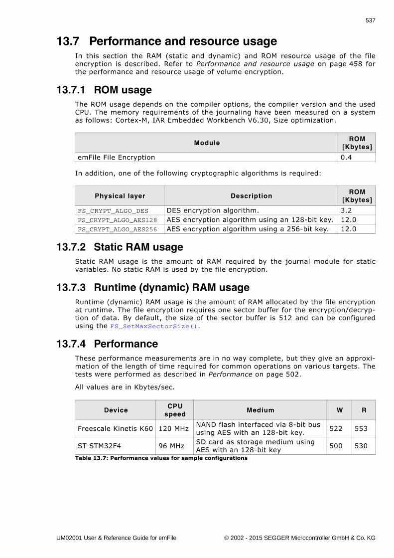
537
13.7 Performance and resource usageIn this section the RAM (static and dynamic) and ROM resource usage of the fileencryption is described. Refer to Performance and resource usage on page 458 forthe performance and resource usage of volume encryption.
13.7.1 ROM usageThe ROM usage depends on the compiler options, the compiler version and the usedCPU. The memory requirements of the journaling have been measured on a systemas follows: Cortex-M, IAR Embedded Workbench V6.30, Size optimization.
In addition, one of the following cryptographic algorithms is required:
13.7.2 Static RAM usageStatic RAM usage is the amount of RAM required by the journal module for staticvariables. No static RAM is used by the file encryption.
13.7.3 Runtime (dynamic) RAM usageRuntime (dynamic) RAM usage is the amount of RAM allocated by the file encryptionat runtime. The file encryption requires one sector buffer for the encryption/decryp-tion of data. By default, the size of the sector buffer is 512 and can be configuredusing the FS_SetMaxSectorSize().
13.7.4 PerformanceThese performance measurements are in no way complete, but they give an approxi-mation of the length of time required for common operations on various targets. Thetests were performed as described in Performance on page 502.
All values are in Kbytes/sec.
ModuleROM
[Kbytes]
emFile File Encryption 0.4
Physical layer DescriptionROM
[Kbytes]
FS_CRYPT_ALGO_DES DES encryption algorithm. 3.2FS_CRYPT_ALGO_AES128 AES encryption algorithm using an 128-bit key. 12.0FS_CRYPT_ALGO_AES256 AES encryption algorithm using a 256-bit key. 12.0
DeviceCPU
speedMedium W R
Freescale Kinetis K60 120 MHz NAND flash interfaced via 8-bit bus using AES with an 128-bit key. 522 553
ST STM32F4 96 MHz SD card as storage medium using AES with an 128-bit key 500 530
Table 13.7: Performance values for sample configurations
UM02001 User & Reference Guide for emFile © 2002 - 2015 SEGGER Microcontroller GmbH & Co. KG

538 CHAPTER 13 Encryption (Add-on)
UM02001 User & Reference Guide for emFile © 2002 - 2015 SEGGER Microcontroller GmbH & Co. KG
539
Chapter 14
Porting emFile 2.x to 3.x
UM02001 User & Reference Guide for emFile © 2002 - 2015 SEGGER Microcontroller GmbH & Co. KG
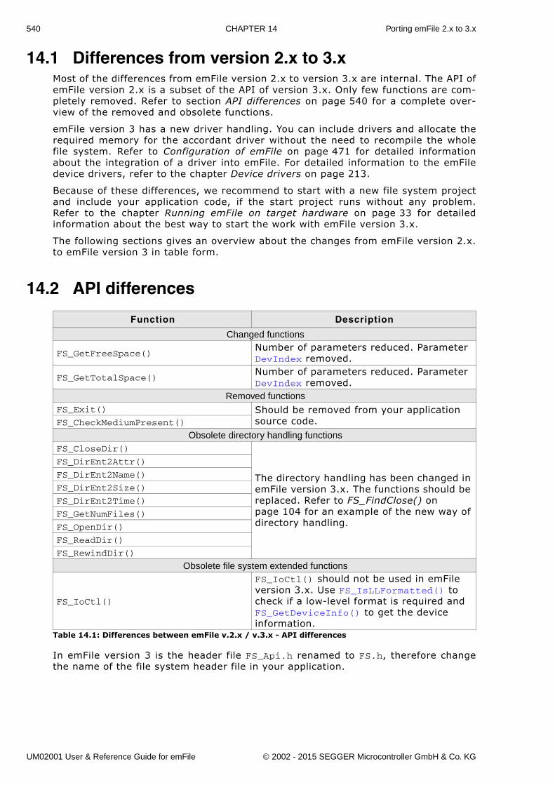
540 CHAPTER 14 Porting emFile 2.x to 3.x
14.1 Differences from version 2.x to 3.xMost of the differences from emFile version 2.x to version 3.x are internal. The API ofemFile version 2.x is a subset of the API of version 3.x. Only few functions are com-pletely removed. Refer to section API differences on page 540 for a complete over-view of the removed and obsolete functions.
emFile version 3 has a new driver handling. You can include drivers and allocate therequired memory for the accordant driver without the need to recompile the wholefile system. Refer to Configuration of emFile on page 471 for detailed informationabout the integration of a driver into emFile. For detailed information to the emFiledevice drivers, refer to the chapter Device drivers on page 213.
Because of these differences, we recommend to start with a new file system projectand include your application code, if the start project runs without any problem.Refer to the chapter Running emFile on target hardware on page 33 for detailedinformation about the best way to start the work with emFile version 3.x.
The following sections gives an overview about the changes from emFile version 2.x.to emFile version 3 in table form.
14.2 API differences
In emFile version 3 is the header file FS_Api.h renamed to FS.h, therefore changethe name of the file system header file in your application.
Function Description
Changed functions
FS_GetFreeSpace()Number of parameters reduced. Parameter DevIndex removed.
FS_GetTotalSpace()Number of parameters reduced. Parameter DevIndex removed.
Removed functionsFS_Exit() Should be removed from your application
source code.FS_CheckMediumPresent()
Obsolete directory handling functionsFS_CloseDir()
The directory handling has been changed in emFile version 3.x. The functions should be replaced. Refer to FS_FindClose() on page 104 for an example of the new way of directory handling.
FS_DirEnt2Attr()
FS_DirEnt2Name()
FS_DirEnt2Size()
FS_DirEnt2Time()
FS_GetNumFiles()
FS_OpenDir()
FS_ReadDir()
FS_RewindDir()
Obsolete file system extended functions
FS_IoCtl()
FS_IoCtl() should not be used in emFile version 3.x. Use FS_IsLLFormatted() to check if a low-level format is required and FS_GetDeviceInfo() to get the device information.
Table 14.1: Differences between emFile v.2.x / v.3.x - API differences
UM02001 User & Reference Guide for emFile © 2002 - 2015 SEGGER Microcontroller GmbH & Co. KG
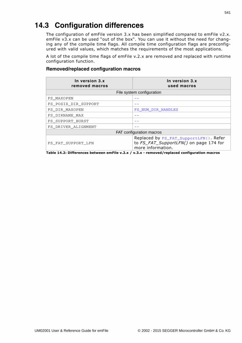
541
14.3 Configuration differencesThe configuration of emFile version 3.x has been simplified compared to emFile v2.x.emFile v3.x can be used �out of the box�. You can use it without the need for chang-ing any of the compile time flags. All compile time configuration flags are preconfig-ured with valid values, which matches the requirements of the most applications.
A lot of the compile time flags of emFile v.2.x are removed and replaced with runtimeconfiguration function.
Removed/replaced configuration macros
In version 3.xremoved macros
In version 3.xused macros
File system configurationFS_MAXOPEN --
FS_POSIX_DIR_SUPPORT --
FS_DIR_MAXOPEN FS_NUM_DIR_HANDLES
FS_DIRNAME_MAX --
FS_SUPPORT_BURST --
FS_DRIVER_ALIGNMENT --
FAT configuration macros
FS_FAT_SUPPORT_LFNReplaced by FS_FAT_SupportLFN(). Refer to FS_FAT_SupportLFN() on page 174 for more information.
Table 14.2: Differences between emFile v.2.x / v.3.x - removed/replaced configuration macros
UM02001 User & Reference Guide for emFile © 2002 - 2015 SEGGER Microcontroller GmbH & Co. KG
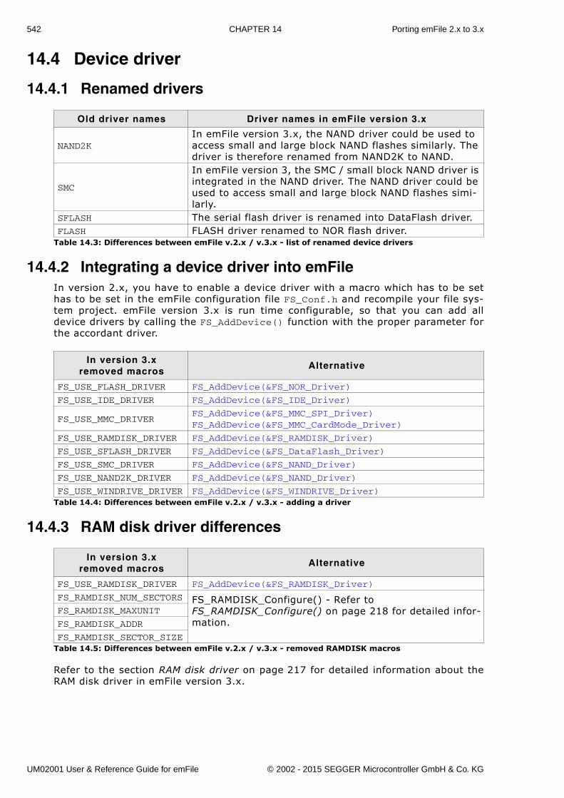
542 CHAPTER 14 Porting emFile 2.x to 3.x
14.4 Device driver
14.4.1 Renamed drivers
14.4.2 Integrating a device driver into emFileIn version 2.x, you have to enable a device driver with a macro which has to be sethas to be set in the emFile configuration file FS_Conf.h and recompile your file sys-tem project. emFile version 3.x is run time configurable, so that you can add alldevice drivers by calling the FS_AddDevice() function with the proper parameter forthe accordant driver.
14.4.3 RAM disk driver differences
Refer to the section RAM disk driver on page 217 for detailed information about theRAM disk driver in emFile version 3.x.
Old driver names Driver names in emFile version 3.x
NAND2KIn emFile version 3.x, the NAND driver could be used to access small and large block NAND flashes similarly. The driver is therefore renamed from NAND2K to NAND.
SMC
In emFile version 3, the SMC / small block NAND driver is integrated in the NAND driver. The NAND driver could be used to access small and large block NAND flashes simi-larly.
SFLASH The serial flash driver is renamed into DataFlash driver.FLASH FLASH driver renamed to NOR flash driver.
Table 14.3: Differences between emFile v.2.x / v.3.x - list of renamed device drivers
In version 3.xremoved macros
Alternative
FS_USE_FLASH_DRIVER FS_AddDevice(&FS_NOR_Driver)
FS_USE_IDE_DRIVER FS_AddDevice(&FS_IDE_Driver)
FS_USE_MMC_DRIVERFS_AddDevice(&FS_MMC_SPI_Driver)FS_AddDevice(&FS_MMC_CardMode_Driver)
FS_USE_RAMDISK_DRIVER FS_AddDevice(&FS_RAMDISK_Driver)
FS_USE_SFLASH_DRIVER FS_AddDevice(&FS_DataFlash_Driver)
FS_USE_SMC_DRIVER FS_AddDevice(&FS_NAND_Driver)
FS_USE_NAND2K_DRIVER FS_AddDevice(&FS_NAND_Driver)
FS_USE_WINDRIVE_DRIVER FS_AddDevice(&FS_WINDRIVE_Driver)Table 14.4: Differences between emFile v.2.x / v.3.x - adding a driver
In version 3.x removed macros
Alternative
FS_USE_RAMDISK_DRIVER FS_AddDevice(&FS_RAMDISK_Driver)
FS_RAMDISK_NUM_SECTORS FS_RAMDISK_Configure() - Refer to FS_RAMDISK_Configure() on page 218 for detailed infor-mation.
FS_RAMDISK_MAXUNIT
FS_RAMDISK_ADDR
FS_RAMDISK_SECTOR_SIZETable 14.5: Differences between emFile v.2.x / v.3.x - removed RAMDISK macros
UM02001 User & Reference Guide for emFile © 2002 - 2015 SEGGER Microcontroller GmbH & Co. KG
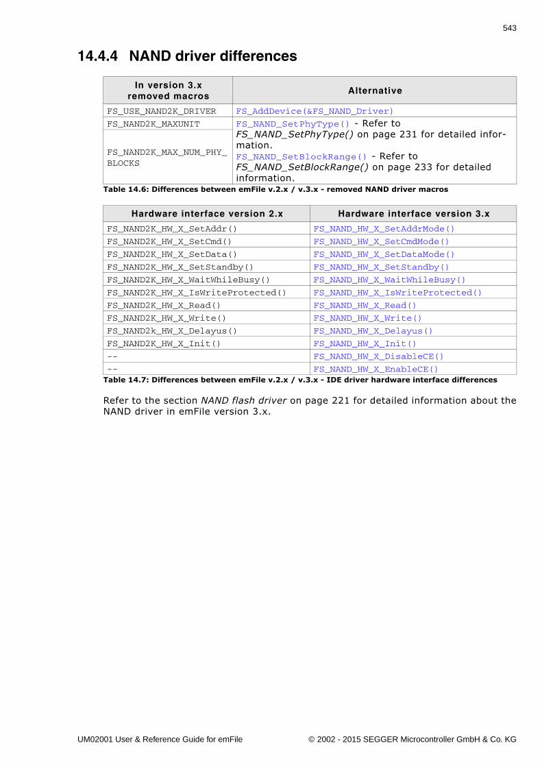
543
14.4.4 NAND driver differences
Refer to the section NAND flash driver on page 221 for detailed information about theNAND driver in emFile version 3.x.
In version 3.xremoved macros
Alternative
FS_USE_NAND2K_DRIVER FS_AddDevice(&FS_NAND_Driver)
FS_NAND2K_MAXUNIT FS_NAND_SetPhyType() - Refer to FS_NAND_SetPhyType() on page 231 for detailed infor-mation.FS_NAND_SetBlockRange() - Refer to FS_NAND_SetBlockRange() on page 233 for detailed information.
FS_NAND2K_MAX_NUM_PHY_BLOCKS
Table 14.6: Differences between emFile v.2.x / v.3.x - removed NAND driver macros
Hardware interface version 2.x Hardware interface version 3.x
FS_NAND2K_HW_X_SetAddr() FS_NAND_HW_X_SetAddrMode()
FS_NAND2K_HW_X_SetCmd() FS_NAND_HW_X_SetCmdMode()
FS_NAND2K_HW_X_SetData() FS_NAND_HW_X_SetDataMode()
FS_NAND2K_HW_X_SetStandby() FS_NAND_HW_X_SetStandby()
FS_NAND2K_HW_X_WaitWhileBusy() FS_NAND_HW_X_WaitWhileBusy()
FS_NAND2K_HW_X_IsWriteProtected() FS_NAND_HW_X_IsWriteProtected()
FS_NAND2K_HW_X_Read() FS_NAND_HW_X_Read()
FS_NAND2K_HW_X_Write() FS_NAND_HW_X_Write()
FS_NAND2k_HW_X_Delayus() FS_NAND_HW_X_Delayus()
FS_NAND2K_HW_X_Init() FS_NAND_HW_X_Init()
-- FS_NAND_HW_X_DisableCE()
-- FS_NAND_HW_X_EnableCE()Table 14.7: Differences between emFile v.2.x / v.3.x - IDE driver hardware interface differences
UM02001 User & Reference Guide for emFile © 2002 - 2015 SEGGER Microcontroller GmbH & Co. KG
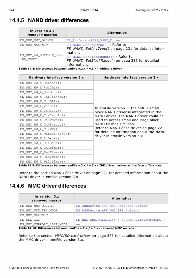
544 CHAPTER 14 Porting emFile 2.x to 3.x
14.4.5 NAND driver differences
Refer to the section NAND flash driver on page 221 for detailed information about theNAND driver in emFile version 3.x.
14.4.6 MMC driver differences
Refer to the section MMC/SD card driver on page 373 for detailed information aboutthe MMC driver in emFile version 3.x.
In version 3.xremoved macros
Alternative
FS_USE_SMC_DRIVER FS_AddDevice(&FS_NAND_Driver)
FS_SMC_MAXUNIT FS_NAND_SetPhyType() - Refer to FS_NAND_SetPhyType() on page 231 for detailed infor-mation.FS_NAND_SetBlockRange() - Refer to FS_NAND_SetBlockRange() on page 233 for detailed information.
FS_SMC_HW_SUPPORT_BSYLINE_CHECK
Table 14.8: Differences between emFile v.2.x / v.3.x - adding a driver
Hardware interface version 2.x Hardware interface version 3.x
FS_SMC_HW_X_SetAddr()
In emFile version 3, the SMC / small block NAND driver is integrated in the NAND driver. The NAND driver could be used to access small and large block NAND flashes similarly. Refer to NAND flash driver on page 221 for detailed information about the NAND driver in emFile version 3.x
FS_SMC_HW_X_SetCmd()
FS_SMC_HW_X_SetData()
FS_SMC_HW_X_SetStandby()
FS_SMC_HW_X_VccOff()
FS_SMC_HW_X_VccOn()
FS_SMC_HW_X_ChkBusy()
FS_SMC_HW_X_ChkCardIn()
FS_SMC_HW_X_ChkPower()
FS_SMC_HW_X_ChkStatus()
FS_SMC_HW_X_ChkWP()
FS_SMC_HW_X_DetectStatus()
FS_SMC_HW_X_InData()
FS_SMC_HW_X_OutData()
FS_SMC_HW_X_ChkTimer()
FS_SMC_HW_X_SetTimer()
FS_SMC_HW_X_StopTimer()
FS_SMC_HW_X_WaitTimer()Table 14.9: Differences between emFile v.2.x / v.3.x - IDE driver hardware interface differences
In version 3.x removed macros
Alternative
FS_USE_MMC_DRIVER FS_AddDevice(&FS_MMC_CardMode_Driver)
FS_MMC_USE_SPI_MODE FS_AddDevice(&FS_MMC_SPI_Driver)
FS_MMC_MAXUNIT --
FS_USE_CRC FS_MMC_ActivateCRC() / FS_MMC_DeactivateCRC()
FS_MMC_SUPPORT_4BIT_MODE --Table 14.10: Differences between emFile v.2.x / v.3.x - removed MMC macros
UM02001 User & Reference Guide for emFile © 2002 - 2015 SEGGER Microcontroller GmbH & Co. KG
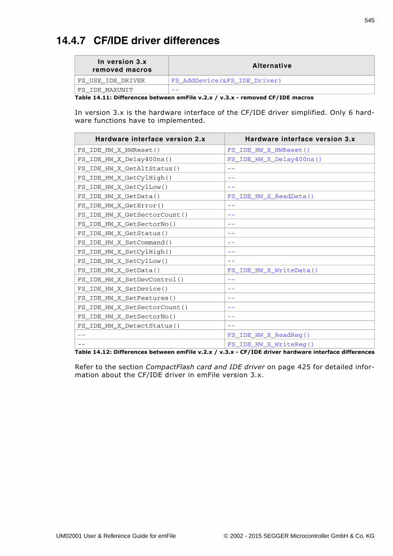
545
14.4.7 CF/IDE driver differences
In version 3.x is the hardware interface of the CF/IDE driver simplified. Only 6 hard-ware functions have to implemented.
Refer to the section CompactFlash card and IDE driver on page 425 for detailed infor-mation about the CF/IDE driver in emFile version 3.x.
In version 3.x removed macros
Alternative
FS_USE_IDE_DRIVER FS_AddDevice(&FS_IDE_Driver)
FS_IDE_MAXUNIT --Table 14.11: Differences between emFile v.2.x / v.3.x - removed CF/IDE macros
Hardware interface version 2.x Hardware interface version 3.x
FS_IDE_HW_X_HWReset() FS_IDE_HW_X_HWReset()
FS_IDE_HW_X_Delay400ns() FS_IDE_HW_X_Delay400ns()
FS_IDE_HW_X_GetAltStatus() --
FS_IDE_HW_X_GetCylHigh() --
FS_IDE_HW_X_GetCylLow() --
FS_IDE_HW_X_GetData() FS_IDE_HW_X_ReadData()
FS_IDE_HW_X_GetError() --
FS_IDE_HW_X_GetSectorCount() --
FS_IDE_HW_X_GetSectorNo() --
FS_IDE_HW_X_GetStatus() --
FS_IDE_HW_X_SetCommand() --
FS_IDE_HW_X_SetCylHigh() --
FS_IDE_HW_X_SetCylLow() --
FS_IDE_HW_X_SetData() FS_IDE_HW_X_WriteData()
FS_IDE_HW_X_SetDevControl() --
FS_IDE_HW_X_SetDevice() --
FS_IDE_HW_X_SetFeatures() --
FS_IDE_HW_X_SetSectorCount() --
FS_IDE_HW_X_SetSectorNo() --
FS_IDE_HW_X_DetectStatus() --
-- FS_IDE_HW_X_ReadReg()
-- FS_IDE_HW_X_WriteReg()Table 14.12: Differences between emFile v.2.x / v.3.x - CF/IDE driver hardware interface differences
UM02001 User & Reference Guide for emFile © 2002 - 2015 SEGGER Microcontroller GmbH & Co. KG
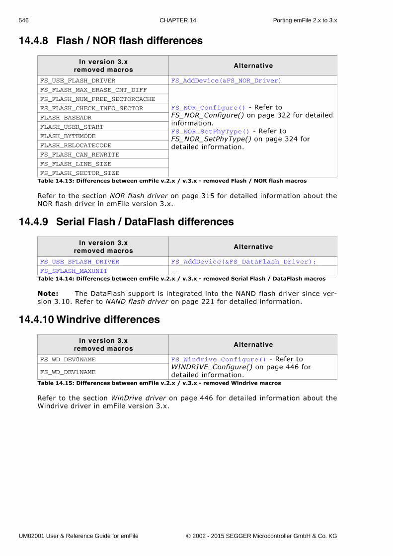
546 CHAPTER 14 Porting emFile 2.x to 3.x
14.4.8 Flash / NOR flash differences
Refer to the section NOR flash driver on page 315 for detailed information about theNOR flash driver in emFile version 3.x.
14.4.9 Serial Flash / DataFlash differences
Note: The DataFlash support is integrated into the NAND flash driver since ver-sion 3.10. Refer to NAND flash driver on page 221 for detailed information.
14.4.10 Windrive differences
Refer to the section WinDrive driver on page 446 for detailed information about theWindrive driver in emFile version 3.x.
In version 3.x removed macros
Alternative
FS_USE_FLASH_DRIVER FS_AddDevice(&FS_NOR_Driver)
FS_FLASH_MAX_ERASE_CNT_DIFF
FS_NOR_Configure() - Refer to FS_NOR_Configure() on page 322 for detailed information.FS_NOR_SetPhyType() - Refer to FS_NOR_SetPhyType() on page 324 for detailed information.
FS_FLASH_NUM_FREE_SECTORCACHE
FS_FLASH_CHECK_INFO_SECTOR
FLASH_BASEADR
FLASH_USER_START
FLASH_BYTEMODE
FLASH_RELOCATECODE
FS_FLASH_CAN_REWRITE
FS_FLASH_LINE_SIZE
FS_FLASH_SECTOR_SIZETable 14.13: Differences between emFile v.2.x / v.3.x - removed Flash / NOR flash macros
In version 3.x removed macros
Alternative
FS_USE_SFLASH_DRIVER FS_AddDevice(&FS_DataFlash_Driver);
FS_SFLASH_MAXUNIT --Table 14.14: Differences between emFile v.2.x / v.3.x - removed Serial Flash / DataFlash macros
In version 3.x removed macros
Alternative
FS_WD_DEV0NAME FS_Windrive_Configure() - Refer to WINDRIVE_Configure() on page 446 for detailed information.FS_WD_DEV1NAME
Table 14.15: Differences between emFile v.2.x / v.3.x - removed Windrive macros
UM02001 User & Reference Guide for emFile © 2002 - 2015 SEGGER Microcontroller GmbH & Co. KG
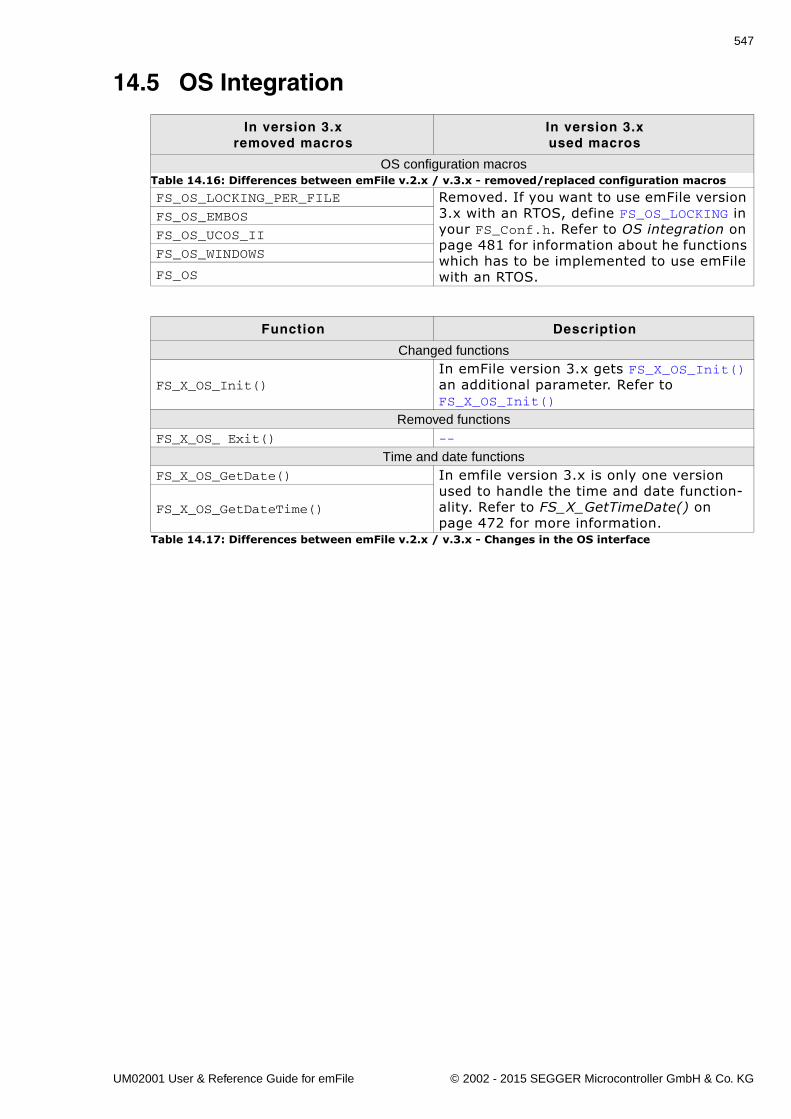
547
14.5 OS Integration
In version 3.xremoved macros
In version 3.xused macros
OS configuration macros
FS_OS_LOCKING_PER_FILE Removed. If you want to use emFile version 3.x with an RTOS, define FS_OS_LOCKING in your FS_Conf.h. Refer to OS integration on page 481 for information about he functions which has to be implemented to use emFile with an RTOS.
FS_OS_EMBOS
FS_OS_UCOS_II
FS_OS_WINDOWS
FS_OS
Table 14.16: Differences between emFile v.2.x / v.3.x - removed/replaced configuration macros
Function Description
Changed functions
FS_X_OS_Init()In emFile version 3.x gets FS_X_OS_Init() an additional parameter. Refer to FS_X_OS_Init()
Removed functionsFS_X_OS_ Exit() --
Time and date functionsFS_X_OS_GetDate() In emfile version 3.x is only one version
used to handle the time and date function-ality. Refer to FS_X_GetTimeDate() on page 472 for more information.
FS_X_OS_GetDateTime()
Table 14.17: Differences between emFile v.2.x / v.3.x - Changes in the OS interface
UM02001 User & Reference Guide for emFile © 2002 - 2015 SEGGER Microcontroller GmbH & Co. KG
548 CHAPTER 14 Porting emFile 2.x to 3.x
UM02001 User & Reference Guide for emFile © 2002 - 2015 SEGGER Microcontroller GmbH & Co. KG
549
Chapter 15
FAQs
You can find in this chapter a collection of frequently asked questions (FAQs)together with answers.
UM02001 User & Reference Guide for emFile © 2002 - 2015 SEGGER Microcontroller GmbH & Co. KG
550 CHAPTER 15 FAQs
15.1 FAQsQ: Is my data safe, when an unexpected RESET occurs?A: In general, the data which is already on the medium is safe. If a read operation is
interrupted, this is completely harmless. If a write operation is interrupted, thedata written in this operation may or may not be stored on the medium, dependingon when the unexpected RESET occurred. In any case, the data which was on themedia prior to the write operation is not affected; directory entries are not messedup, the file-allocation-table is kept in order. This is true if your storage medium isnot affected by the RESET, meaning that it is able to complete a pending writeoperation. (Which is typically the case with Flash memory cards other than SMC)
Q: I use FAT and I can only create a limited number of root directory entries. Why?A: With FAT12 and FAT16 the root directory is special because it has a fixed size. Dur-
ing media format one can determine the size, but once formatted this value is con-stant and determines the number of entries the root directory can hold. FAT32does not have this limitation and the root directory's size can be variable.
Microsoft's �FAT32 File System Specification� says on page 22: �For FAT12 andFAT16 media, the root directory is located in a fixed location on the disk immedi-ately following the last FAT and is of a fixed size in sectors computed from theBPB_RootEntCnt value [...] For FAT32, the root directory can be of variable sizeand is a cluster chain, just like any other directory is.�. Here BPB_RootEntCntspecifies the count of 32-byte directory entries in the root directory and as thecitation says, the number of sectors is computed from this value.
In addition, which file system is used depends on the size of the medium, that isthe number of clusters and the cluster size, where each cluster contains one ormore sectors. Using small cluster sizes (for example cluster size = 512 bytes) onecan use FAT32 on media with more than 32 MB. (FAT16 can address at least 216clusters with a 512 byte cluster size. That is 65536 * 512 = 33554432 bytes =32768 KB = 32 MB). If the media is smaller than or equal to 32 MB or the clustersize is greater than 512 bytes, FAT32 cannot be used.
To actually set a custom root directory size for FAT12/FAT16 one can use theemFile API function int FS_Format(const char * pDevice, FS_FORMAT_INFO *pFormatInfo); where FS_FORMAT_INFO is declared as:
typedef struct { U16 SectorsPerCluster; U16 NumRootDirEntries; FS_DEV_INFO * pDevInfo;} FS_FORMAT_INFO;
Set NumRootDirEntries to the desired number of root directory entries you wantto store.
UM02001 User & Reference Guide for emFile © 2002 - 2015 SEGGER Microcontroller GmbH & Co. KG
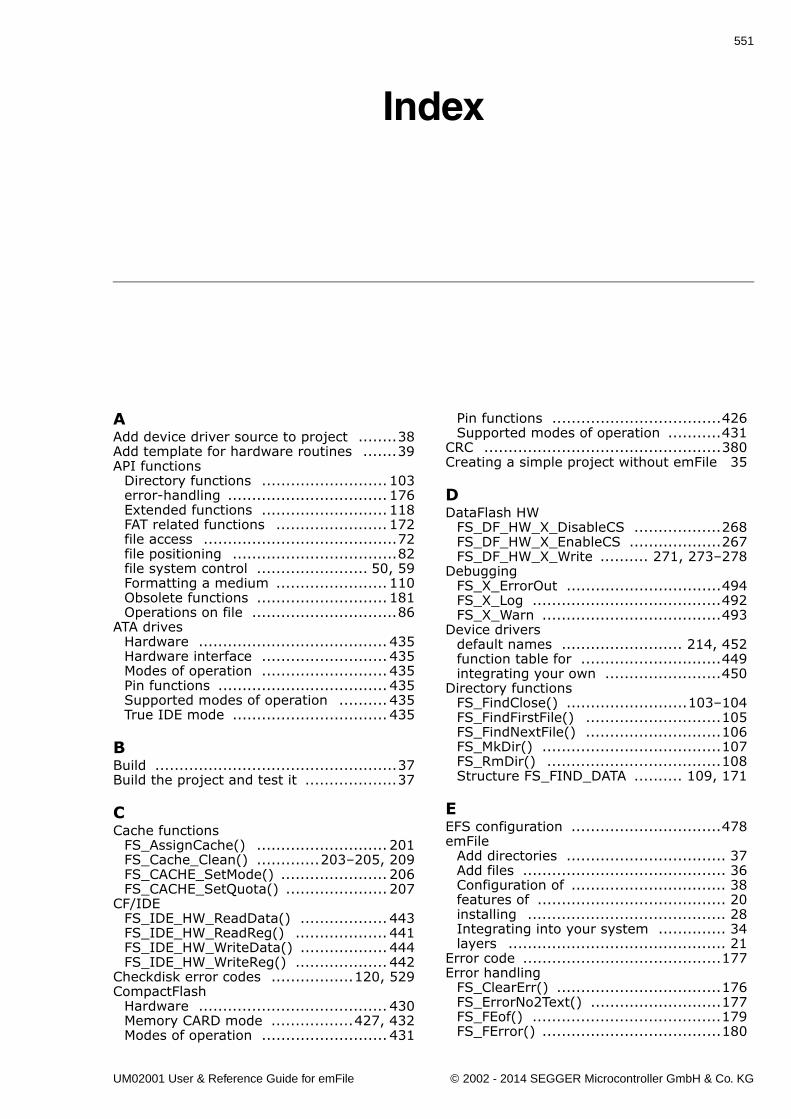
551
Index
AAdd device driver source to project ........38Add template for hardware routines .......39API functions
Directory functions .......................... 103error-handling ................................. 176Extended functions .......................... 118FAT related functions ....................... 172file access ........................................72file positioning ..................................82file system control ....................... 50, 59Formatting a medium ....................... 110Obsolete functions ........................... 181Operations on file ..............................86
ATA drivesHardware ....................................... 435Hardware interface .......................... 435Modes of operation .......................... 435Pin functions ................................... 435Supported modes of operation .......... 435True IDE mode ................................ 435
BBuild ..................................................37Build the project and test it ...................37
CCache functions
FS_AssignCache() ........................... 201FS_Cache_Clean() .............203�205, 209FS_CACHE_SetMode() ...................... 206FS_CACHE_SetQuota() ..................... 207
CF/IDEFS_IDE_HW_ReadData() .................. 443FS_IDE_HW_ReadReg() ................... 441FS_IDE_HW_WriteData() .................. 444FS_IDE_HW_WriteReg() ................... 442
Checkdisk error codes .................120, 529CompactFlash
Hardware ....................................... 430Memory CARD mode .................427, 432Modes of operation .......................... 431
Pin functions ...................................426Supported modes of operation ...........431
CRC .................................................380Creating a simple project without emFile 35
DDataFlash HW
FS_DF_HW_X_DisableCS ..................268FS_DF_HW_X_EnableCS ...................267FS_DF_HW_X_Write .......... 271, 273�278
DebuggingFS_X_ErrorOut ................................494FS_X_Log .......................................492FS_X_Warn .....................................493
Device driversdefault names ......................... 214, 452function table for .............................449integrating your own ........................450
Directory functionsFS_FindClose() .........................103�104FS_FindFirstFile() ............................105FS_FindNextFile() ............................106FS_MkDir() .....................................107FS_RmDir() ....................................108Structure FS_FIND_DATA .......... 109, 171
EEFS configuration ...............................478emFile
Add directories ................................. 37Add files .......................................... 36Configuration of ................................ 38features of ....................................... 20installing ......................................... 28Integrating into your system .............. 34layers ............................................. 21
Error code .........................................177Error handling
FS_ClearErr() ..................................176FS_ErrorNo2Text() ...........................177FS_FEof() .......................................179FS_FError() .....................................180
UM02001 User & Reference Guide for emFile © 2002 - 2014 SEGGER Microcontroller GmbH & Co. KG
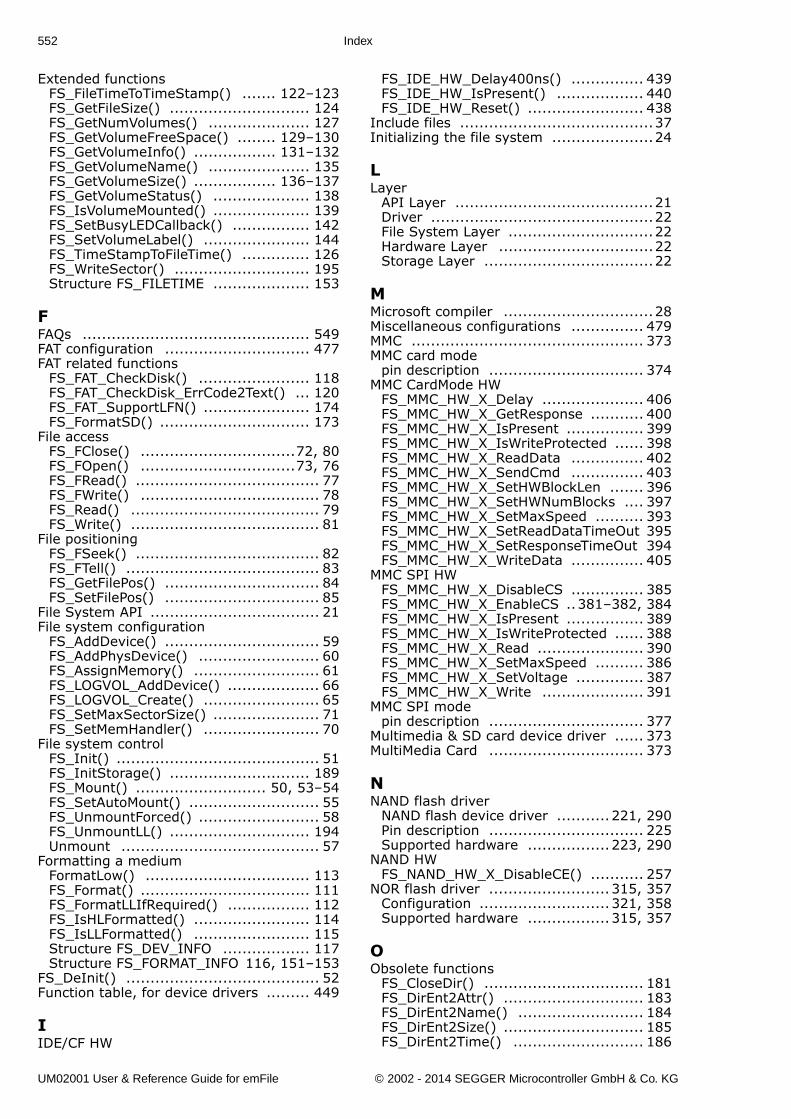
552 Index
Extended functionsFS_FileTimeToTimeStamp() ....... 122�123FS_GetFileSize() ............................. 124FS_GetNumVolumes() ..................... 127FS_GetVolumeFreeSpace() ........ 129�130FS_GetVolumeInfo() ................. 131�132FS_GetVolumeName() ..................... 135FS_GetVolumeSize() ................. 136�137FS_GetVolumeStatus() .................... 138FS_IsVolumeMounted() .................... 139FS_SetBusyLEDCallback() ................ 142FS_SetVolumeLabel() ...................... 144FS_TimeStampToFileTime() .............. 126FS_WriteSector() ............................ 195Structure FS_FILETIME .................... 153
FFAQs ............................................... 549FAT configuration .............................. 477FAT related functions
FS_FAT_CheckDisk() ....................... 118FS_FAT_CheckDisk_ErrCode2Text() ... 120FS_FAT_SupportLFN() ...................... 174FS_FormatSD() ............................... 173
File accessFS_FClose() ................................72, 80FS_FOpen() ................................73, 76FS_FRead() ...................................... 77FS_FWrite() ..................................... 78FS_Read() ....................................... 79FS_Write() ....................................... 81
File positioningFS_FSeek() ...................................... 82FS_FTell() ........................................ 83FS_GetFilePos() ................................ 84FS_SetFilePos() ................................ 85
File System API ................................... 21File system configuration
FS_AddDevice() ................................ 59FS_AddPhysDevice() ......................... 60FS_AssignMemory() .......................... 61FS_LOGVOL_AddDevice() ................... 66FS_LOGVOL_Create() ........................ 65FS_SetMaxSectorSize() ...................... 71FS_SetMemHandler() ........................ 70
File system controlFS_Init() .......................................... 51FS_InitStorage() ............................. 189FS_Mount() ........................... 50, 53�54FS_SetAutoMount() ........................... 55FS_UnmountForced() ......................... 58FS_UnmountLL() ............................. 194Unmount ......................................... 57
Formatting a mediumFormatLow() .................................. 113FS_Format() ................................... 111FS_FormatLLIfRequired() ................. 112FS_IsHLFormatted() ........................ 114FS_IsLLFormatted() ........................ 115Structure FS_DEV_INFO .................. 117Structure FS_FORMAT_INFO 116, 151�153
FS_DeInit() ........................................ 52Function table, for device drivers ......... 449
IIDE/CF HW
FS_IDE_HW_Delay400ns() ............... 439FS_IDE_HW_IsPresent() .................. 440FS_IDE_HW_Reset() ........................ 438
Include files ........................................37Initializing the file system .....................24
LLayer
API Layer .........................................21Driver ..............................................22File System Layer ..............................22Hardware Layer ................................22Storage Layer ...................................22
MMicrosoft compiler ...............................28Miscellaneous configurations ............... 479MMC ................................................ 373MMC card mode
pin description ................................ 374MMC CardMode HW
FS_MMC_HW_X_Delay ..................... 406FS_MMC_HW_X_GetResponse ........... 400FS_MMC_HW_X_IsPresent ................ 399FS_MMC_HW_X_IsWriteProtected ...... 398FS_MMC_HW_X_ReadData ............... 402FS_MMC_HW_X_SendCmd ............... 403FS_MMC_HW_X_SetHWBlockLen ....... 396FS_MMC_HW_X_SetHWNumBlocks .... 397FS_MMC_HW_X_SetMaxSpeed .......... 393FS_MMC_HW_X_SetReadDataTimeOut 395FS_MMC_HW_X_SetResponseTimeOut 394FS_MMC_HW_X_WriteData ............... 405
MMC SPI HWFS_MMC_HW_X_DisableCS ............... 385FS_MMC_HW_X_EnableCS ..381�382, 384FS_MMC_HW_X_IsPresent ................ 389FS_MMC_HW_X_IsWriteProtected ...... 388FS_MMC_HW_X_Read ...................... 390FS_MMC_HW_X_SetMaxSpeed .......... 386FS_MMC_HW_X_SetVoltage .............. 387FS_MMC_HW_X_Write ..................... 391
MMC SPI modepin description ................................ 377
Multimedia & SD card device driver ...... 373MultiMedia Card ................................ 373
NNAND flash driver
NAND flash device driver ...........221, 290Pin description ................................ 225Supported hardware .................223, 290
NAND HWFS_NAND_HW_X_DisableCE() ........... 257
NOR flash driver .........................315, 357Configuration ...........................321, 358Supported hardware .................315, 357
OObsolete functions
FS_CloseDir() ................................. 181FS_DirEnt2Attr() ............................. 183FS_DirEnt2Name() .......................... 184FS_DirEnt2Size() ............................. 185FS_DirEnt2Time() ........................... 186
UM02001 User & Reference Guide for emFile © 2002 - 2014 SEGGER Microcontroller GmbH & Co. KG
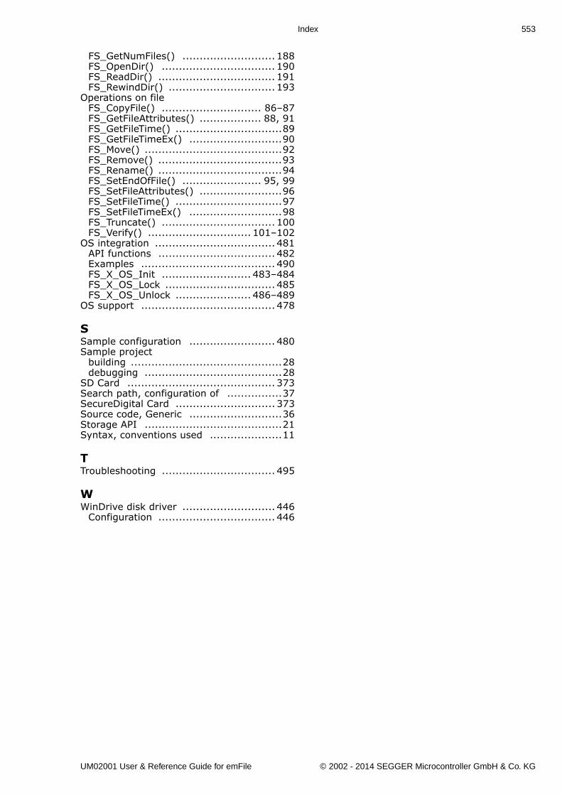
Index 553
FS_GetNumFiles() ........................... 188FS_OpenDir() ................................. 190FS_ReadDir() .................................. 191FS_RewindDir() ............................... 193
Operations on fileFS_CopyFile() ............................. 86�87FS_GetFileAttributes() .................. 88, 91FS_GetFileTime() ...............................89FS_GetFileTimeEx() ...........................90FS_Move() ........................................92FS_Remove() ....................................93FS_Rename() ....................................94FS_SetEndOfFile() ....................... 95, 99FS_SetFileAttributes() ........................96FS_SetFileTime() ...............................97FS_SetFileTimeEx() ...........................98FS_Truncate() ................................. 100FS_Verify() .............................. 101�102
OS integration ................................... 481API functions .................................. 482Examples ....................................... 490FS_X_OS_Init .......................... 483�484FS_X_OS_Lock ................................ 485FS_X_OS_Unlock ...................... 486�489
OS support ....................................... 478
SSample configuration ......................... 480Sample project
building ............................................28debugging ........................................28
SD Card ........................................... 373Search path, configuration of ................37SecureDigital Card ............................. 373Source code, Generic ...........................36Storage API ........................................21Syntax, conventions used .....................11
TTroubleshooting ................................. 495
WWinDrive disk driver ........................... 446
Configuration .................................. 446
UM02001 User & Reference Guide for emFile © 2002 - 2014 SEGGER Microcontroller GmbH & Co. KG

554 Index
UM02001 User & Reference Guide for emFile © 2002 - 2014 SEGGER Microcontroller GmbH & Co. KG