Embed Size (px)
Citation preview
Reference Manual00809-0100-4075, Rev CD
July 2017
Emerson™ Wireless 775 THUM™ Adapter

Reference Manual 00809-0100-4075, Rev CB
ContentsJuly 2017
Contents
1Section 1: Introduction1.1 Using the manual . . . . . . . . . . . . . . . . . . . . . . . . . . . . . . . . . . . . . . . . . . . . . . . . . . . . . . . . . . . . . . . . 1
1.2 Features . . . . . . . . . . . . . . . . . . . . . . . . . . . . . . . . . . . . . . . . . . . . . . . . . . . . . . . . . . . . . . . . . . . . . . . . 2
1.3 Considerations . . . . . . . . . . . . . . . . . . . . . . . . . . . . . . . . . . . . . . . . . . . . . . . . . . . . . . . . . . . . . . . . . . 2
1.3.1 General . . . . . . . . . . . . . . . . . . . . . . . . . . . . . . . . . . . . . . . . . . . . . . . . . . . . . . . . . . . . . . . . . . . . . 2
1.3.2 Commissioning. . . . . . . . . . . . . . . . . . . . . . . . . . . . . . . . . . . . . . . . . . . . . . . . . . . . . . . . . . . . . . 2
1.3.3 Mechanical. . . . . . . . . . . . . . . . . . . . . . . . . . . . . . . . . . . . . . . . . . . . . . . . . . . . . . . . . . . . . . . . . . 2
1.3.4 Electrical. . . . . . . . . . . . . . . . . . . . . . . . . . . . . . . . . . . . . . . . . . . . . . . . . . . . . . . . . . . . . . . . . . . . 2
1.3.5 Environmental. . . . . . . . . . . . . . . . . . . . . . . . . . . . . . . . . . . . . . . . . . . . . . . . . . . . . . . . . . . . . . . 2
1.3.6 Wireless considerations. . . . . . . . . . . . . . . . . . . . . . . . . . . . . . . . . . . . . . . . . . . . . . . . . . . . . . . 3
1.4 Product recycling/disposal . . . . . . . . . . . . . . . . . . . . . . . . . . . . . . . . . . . . . . . . . . . . . . . . . . . . . . . . 4
2Section 2: Configuration2.1 Safety messages . . . . . . . . . . . . . . . . . . . . . . . . . . . . . . . . . . . . . . . . . . . . . . . . . . . . . . . . . . . . . . . . . 5
2.2 Connections. . . . . . . . . . . . . . . . . . . . . . . . . . . . . . . . . . . . . . . . . . . . . . . . . . . . . . . . . . . . . . . . . . . . . 5
2.3 Device sensor configuration . . . . . . . . . . . . . . . . . . . . . . . . . . . . . . . . . . . . . . . . . . . . . . . . . . . . . . . 5
2.4 Connection diagrams. . . . . . . . . . . . . . . . . . . . . . . . . . . . . . . . . . . . . . . . . . . . . . . . . . . . . . . . . . . . . 6
2.5 Device network configuration . . . . . . . . . . . . . . . . . . . . . . . . . . . . . . . . . . . . . . . . . . . . . . . . . . . . . 7
2.5.1 Join device to network . . . . . . . . . . . . . . . . . . . . . . . . . . . . . . . . . . . . . . . . . . . . . . . . . . . . . . . . 7
2.5.2 Configure update rate . . . . . . . . . . . . . . . . . . . . . . . . . . . . . . . . . . . . . . . . . . . . . . . . . . . . . . . . 7
2.5.3 Configure THUM Adapter long tag . . . . . . . . . . . . . . . . . . . . . . . . . . . . . . . . . . . . . . . . . . . . . 8
2.5.4 Wired device tag. . . . . . . . . . . . . . . . . . . . . . . . . . . . . . . . . . . . . . . . . . . . . . . . . . . . . . . . . . . . . 8
2.6 HART tree . . . . . . . . . . . . . . . . . . . . . . . . . . . . . . . . . . . . . . . . . . . . . . . . . . . . . . . . . . . . . . . . . . . . . . . 9
3Section 3: Mounting3.1 Safety messages . . . . . . . . . . . . . . . . . . . . . . . . . . . . . . . . . . . . . . . . . . . . . . . . . . . . . . . . . . . . . . . . 11
3.2 Mounting . . . . . . . . . . . . . . . . . . . . . . . . . . . . . . . . . . . . . . . . . . . . . . . . . . . . . . . . . . . . . . . . . . . . . . 12
3.2.1 Direct mount . . . . . . . . . . . . . . . . . . . . . . . . . . . . . . . . . . . . . . . . . . . . . . . . . . . . . . . . . . . . . . . 12
3.2.2 Remote mount . . . . . . . . . . . . . . . . . . . . . . . . . . . . . . . . . . . . . . . . . . . . . . . . . . . . . . . . . . . . . 13
3.2.3 Power supply . . . . . . . . . . . . . . . . . . . . . . . . . . . . . . . . . . . . . . . . . . . . . . . . . . . . . . . . . . . . . . . 13
3.2.4 Load resistor . . . . . . . . . . . . . . . . . . . . . . . . . . . . . . . . . . . . . . . . . . . . . . . . . . . . . . . . . . . . . . . 13
3.2.5 Wiring . . . . . . . . . . . . . . . . . . . . . . . . . . . . . . . . . . . . . . . . . . . . . . . . . . . . . . . . . . . . . . . . . . . . . 13
3.3 Loop current test. . . . . . . . . . . . . . . . . . . . . . . . . . . . . . . . . . . . . . . . . . . . . . . . . . . . . . . . . . . . . . . . 24
iiiContents

Reference Manual00809-0100-4075, Rev CB
ContentsJuly 2017
4Section 4: Commissioning4.1 Safety messages . . . . . . . . . . . . . . . . . . . . . . . . . . . . . . . . . . . . . . . . . . . . . . . . . . . . . . . . . . . . . . . . 27
4.2 Device network configuration . . . . . . . . . . . . . . . . . . . . . . . . . . . . . . . . . . . . . . . . . . . . . . . . . . . . 27
4.2.1 Network status . . . . . . . . . . . . . . . . . . . . . . . . . . . . . . . . . . . . . . . . . . . . . . . . . . . . . . . . . . . . . 28
4.2.2 Verify operation . . . . . . . . . . . . . . . . . . . . . . . . . . . . . . . . . . . . . . . . . . . . . . . . . . . . . . . . . . . . 29
5Section 5: Operation and maintenance5.1 Safety messages . . . . . . . . . . . . . . . . . . . . . . . . . . . . . . . . . . . . . . . . . . . . . . . . . . . . . . . . . . . . . . . . 31
5.2 Startup sequence . . . . . . . . . . . . . . . . . . . . . . . . . . . . . . . . . . . . . . . . . . . . . . . . . . . . . . . . . . . . . . . 31
5.3 Advanced setup. . . . . . . . . . . . . . . . . . . . . . . . . . . . . . . . . . . . . . . . . . . . . . . . . . . . . . . . . . . . . . . . . 32
5.3.1 Configure advanced update rate . . . . . . . . . . . . . . . . . . . . . . . . . . . . . . . . . . . . . . . . . . . . . . 32
5.3.2 4-20 mA current . . . . . . . . . . . . . . . . . . . . . . . . . . . . . . . . . . . . . . . . . . . . . . . . . . . . . . . . . . . . 32
5.3.3 Voltage drop . . . . . . . . . . . . . . . . . . . . . . . . . . . . . . . . . . . . . . . . . . . . . . . . . . . . . . . . . . . . . . . 32
5.3.4 Discovery mode . . . . . . . . . . . . . . . . . . . . . . . . . . . . . . . . . . . . . . . . . . . . . . . . . . . . . . . . . . . . 32
5.3.5 Configure HART polling. . . . . . . . . . . . . . . . . . . . . . . . . . . . . . . . . . . . . . . . . . . . . . . . . . . . . . 33
5.3.6 Configure router only mode. . . . . . . . . . . . . . . . . . . . . . . . . . . . . . . . . . . . . . . . . . . . . . . . . . 33
5.3.7 HART address . . . . . . . . . . . . . . . . . . . . . . . . . . . . . . . . . . . . . . . . . . . . . . . . . . . . . . . . . . . . . . 33
5.3.8 HART master . . . . . . . . . . . . . . . . . . . . . . . . . . . . . . . . . . . . . . . . . . . . . . . . . . . . . . . . . . . . . . . 33
6Section 6: Troubleshooting6.1 Overview . . . . . . . . . . . . . . . . . . . . . . . . . . . . . . . . . . . . . . . . . . . . . . . . . . . . . . . . . . . . . . . . . . . . . . 35
6.2 Service support . . . . . . . . . . . . . . . . . . . . . . . . . . . . . . . . . . . . . . . . . . . . . . . . . . . . . . . . . . . . . . . . . 37
AAppendix A: Specifications and Reference DataA.1 Functional specifications . . . . . . . . . . . . . . . . . . . . . . . . . . . . . . . . . . . . . . . . . . . . . . . . . . . . . . . . . 39
A.2 Physical specifications . . . . . . . . . . . . . . . . . . . . . . . . . . . . . . . . . . . . . . . . . . . . . . . . . . . . . . . . . . . 39
A.3 Performance specifications. . . . . . . . . . . . . . . . . . . . . . . . . . . . . . . . . . . . . . . . . . . . . . . . . . . . . . . 40
A.4 Dimensional drawings . . . . . . . . . . . . . . . . . . . . . . . . . . . . . . . . . . . . . . . . . . . . . . . . . . . . . . . . . . . 41
A.5 Ordering information. . . . . . . . . . . . . . . . . . . . . . . . . . . . . . . . . . . . . . . . . . . . . . . . . . . . . . . . . . . . 43
A.6 Accessories and spare parts . . . . . . . . . . . . . . . . . . . . . . . . . . . . . . . . . . . . . . . . . . . . . . . . . . . . . . 44
BAppendix B: Product CertificationsB.1 European Directive Information. . . . . . . . . . . . . . . . . . . . . . . . . . . . . . . . . . . . . . . . . . . . . . . . . . . 45
B.2 Ordinary Location Certification from FM Approvals . . . . . . . . . . . . . . . . . . . . . . . . . . . . . . . . . . 45
B.3 Telecommunication compliance (for wireless products only) . . . . . . . . . . . . . . . . . . . . . . . . . 45
B.4 FCC and IC (for wireless products only) . . . . . . . . . . . . . . . . . . . . . . . . . . . . . . . . . . . . . . . . . . . . 45
B.5 Installing Equipment in North America. . . . . . . . . . . . . . . . . . . . . . . . . . . . . . . . . . . . . . . . . . . . . 45
B.6 USA . . . . . . . . . . . . . . . . . . . . . . . . . . . . . . . . . . . . . . . . . . . . . . . . . . . . . . . . . . . . . . . . . . . . . . . . . . . 45
iv Contents
Reference Manual 00809-0100-4075, Rev CB
ContentsJuly 2017
B.7 Canada . . . . . . . . . . . . . . . . . . . . . . . . . . . . . . . . . . . . . . . . . . . . . . . . . . . . . . . . . . . . . . . . . . . . . . . . 46
B.8 Europe. . . . . . . . . . . . . . . . . . . . . . . . . . . . . . . . . . . . . . . . . . . . . . . . . . . . . . . . . . . . . . . . . . . . . . . . . 46
B.9 International . . . . . . . . . . . . . . . . . . . . . . . . . . . . . . . . . . . . . . . . . . . . . . . . . . . . . . . . . . . . . . . . . . . 46
B.10 Brazil . . . . . . . . . . . . . . . . . . . . . . . . . . . . . . . . . . . . . . . . . . . . . . . . . . . . . . . . . . . . . . . . . . . . . . . . . . 46
B.11 China . . . . . . . . . . . . . . . . . . . . . . . . . . . . . . . . . . . . . . . . . . . . . . . . . . . . . . . . . . . . . . . . . . . . . . . . . . 47
B.12 Japan . . . . . . . . . . . . . . . . . . . . . . . . . . . . . . . . . . . . . . . . . . . . . . . . . . . . . . . . . . . . . . . . . . . . . . . . . . 47
B.13 EAC - Belarus, Kazakhstan, Russia . . . . . . . . . . . . . . . . . . . . . . . . . . . . . . . . . . . . . . . . . . . . . . . . . 47
B.14 Republic of Korea . . . . . . . . . . . . . . . . . . . . . . . . . . . . . . . . . . . . . . . . . . . . . . . . . . . . . . . . . . . . . . . 47
B.15 India. . . . . . . . . . . . . . . . . . . . . . . . . . . . . . . . . . . . . . . . . . . . . . . . . . . . . . . . . . . . . . . . . . . . . . . . . . . 47
B.16 Combinations . . . . . . . . . . . . . . . . . . . . . . . . . . . . . . . . . . . . . . . . . . . . . . . . . . . . . . . . . . . . . . . . . . 47
vContents

vi
Reference Manual00809-0100-4075, Rev CB
ContentsJuly 2017
Contents
Reference Manual 00809-0100-4075, Rev CB
Title PageJuly 2017
Emerson™ Wireless 775 THUM™ Adapter
Emerson Wireless 775 THUM Adapter Hardware Revision 1 HART® Device Revision 1Field Communicator Field Device Revision Dev v2.5 DD v4
NOTICE
Read this manual before working with the product. For personal and system safety, and for optimum product performance, make sure to thoroughly understand the contents before installing, using, or maintaining this product.
The United States has two toll-free assistance numbers and one international number.
Customer Central1 800 999 9307 (7:00 a.m. to 7:00 p.m. CST)
National Response Center1 800 654 7768 (24 hours a day)Equipment service needs
International1 952 906 8888
The products described in this document are NOT designed for nuclear-qualified applications.
Using non-nuclear qualified products in applications that require nuclear-qualified hardware or products may cause inaccurate readings.
For information on Rosemount nuclear-qualified products, contact an Emerson Sales Representative.
Explosions could result in death or serious injury.
Installation of this transmitter in an explosive environment must be in accordance with the appropriate local, national, and international standards, codes, and practices. Review the Product Certifications section for any restrictions associated with a safe installation.
Before connecting a Field Communicator in an explosive atmosphere, ensure the instruments are installed in accordance with intrinsically safe or non-incendive field wiring practices.
Electrical shock can result in death or serious injury.
Avoid contact with the leads and terminals. High voltage that may be present on leads can cause electrical shock.
This device complies with Part 15 of the FCC Rules. Operation is subject to the following conditions. This device may not cause harmful interference. This device must accept any interference received, including interference that may cause undesired operation.
This device must be installed to ensure a minimum antenna separation distance of 20 cm from all persons.
vTitle Page
Reference Manual00809-0100-4075, Rev CB
Title PageJuly 2017
NOTICE
The THUM Adapter and all other wireless devices should be installed only after the Emerson Wireless Gateway has been installed and is functioning properly. Wireless devices should also be powered up in order of proximity from the Gateway, beginning with the closest. This will result in a simpler and faster network installation.
During normal operation, or in fault condition, the THUM Adapter will cause a 2.5 V drop in the connected loop. It is important to ensure that the power supply can provide at least 2.5 V more than the lift off voltage of the wired device to make sure it works properly with the THUM Adapter installed. To determine the lift off voltage for the wired device, review the wired device operation and installation manual.
vi Title Page
Reference Manual 00809-0100-4075, Rev CB
IntroductionJuly 2017
Section 1 Introduction
1.1 Using the manualThis manual is designed to assist in the installation, operation, and maintenance of the Emerson™ Wireless 775 THUM™ Adapter.
Section 1: Introduction Manual and transmitter overview
Considerations
Section 2: Configuration Device Sensor Configuration
Device Network Configuration
Section 3: Mounting Mount the Sensor
Sensor Assembly/Leads
Grounding
Section 4: Commissioning Network Status
Verify Operation
Section 5: Operation and maintenance Startup Sequence
Advanced Setup
Section 6: Troubleshooting Troubleshooting recommended actions
Service support
Appendix A: Specifications and Reference Data Specifications
Dimensional Drawings
Ordering Information
Appendix B: Product Certifications Product Certifications
Installation Drawings
1Introduction

Reference Manual00809-0100-4075, Rev CB
IntroductionJuly 2017
1.2 Features An installation-ready solution that provides rich wireless HART® data
Works with any 2- or 4-wire HART devices
Flexibility to meet your most demanding applications
Wireless output with >99% data reliability delivers rich HART data, protected by industry leading security
Gain access to additional HART information, such as diagnostics or multi-variable data
Add wireless to almost any measurement point without affecting the approval of the sub-device
IEC 62591 (WirelessHART®) capabilities extend the full benefits of Plantweb™ to previously inaccessible locations
1.3 Considerations
1.3.1 GeneralThe THUM Adapter is connected to a HART sub-device. With simple HART configuration, the THUM transmits the HART information from the sub-device into the Wireless network.
1.3.2 CommissioningThe THUM Adapted can be commissioned before or after installation. It may be useful to bench commission the THUM Adapter before installation to ensure proper operation and to become familiar with the functionality. The instruments should be installed in accordance with intrinsically safe or non-incendive field wiring practices, when required. The THUM Adapter is powered when connected to a powered loop.
1.3.3 MechanicalWhen choosing an installation location and position for the transmitter, take into account access to the device. For best performance, the antenna should be vertical and have some space between objects in a parallel metal plane such as a pipe or metal framework, as the pipes or framework may adversely affect the performance of the antenna.
1.3.4 ElectricalThe THUM Adapter is connected into a powered 4–20 mA loop, powering itself by scavenging power. The THUM Adapter causes a voltage drop across the loop. The drop is linear from 2.25 volts at 3.5 mA to 1.2 volts at 25 mA, but does not effect the 4–20 mA signal on the loop. Under fault conditions, the maximum voltage drop is 2.5 volts.
1.3.5 EnvironmentalVerify that the operating environment of the transmitter is consistent with the appropriate hazardous locations certifications.
2 Introduction
Reference Manual 00809-0100-4075, Rev CB
IntroductionJuly 2017
Temperature limits
1.3.6 Wireless considerations
Power up sequencePower should not be applied to any wireless device until the Gateway is installed and functioning properly. Wireless devices should also be powered up in order of proximity from the Gateway, beginning with the closest. This will result in a simpler and faster network installation. Enable active advertising on the Gateway to ensure that new devices join the network faster. For more information see the Emerson Wireless 1420 Gateway Reference Manual.
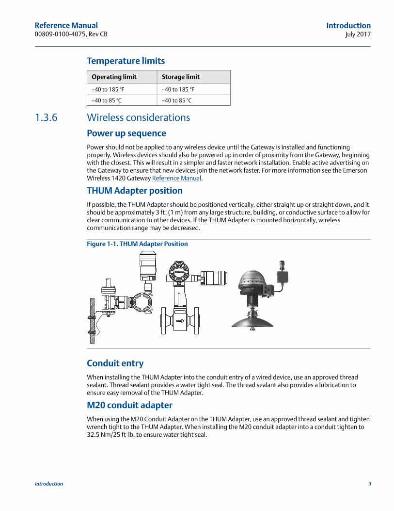
THUM Adapter positionIf possible, the THUM Adapter should be positioned vertically, either straight up or straight down, and it should be approximately 3 ft. (1 m) from any large structure, building, or conductive surface to allow for clear communication to other devices. If the THUM Adapter is mounted horizontally, wireless communication range may be decreased.
Figure 1-1. THUM Adapter Position
Conduit entryWhen installing the THUM Adapter into the conduit entry of a wired device, use an approved thread sealant. Thread sealant provides a water tight seal. The thread sealant also provides a lubrication to ensure easy removal of the THUM Adapter.
M20 conduit adapterWhen using the M20 Conduit Adapter on the THUM Adapter, use an approved thread sealant and tighten wrench tight to the THUM Adapter. When installing the M20 conduit adapter into a conduit tighten to 32.5 Nm/25 ft-lb. to ensure water tight seal.
Operating limit Storage limit
–40 to 185 °F –40 to 185 °F
–40 to 85 °C –40 to 85 °C
3Introduction
Reference Manual00809-0100-4075, Rev CB
IntroductionJuly 2017
Field Communicator connectionsIn order for the Field Communicator to interface with the THUM Adapter, the wired device must be powered. The Field Communicator must be put into poll mode and should use the THUM Adapter address of 63.
Power supplyMinimum loop load of 250 Ohms.The THUM Adapter communicates and derives power from a standard 4-20 mA/HART loop. The THUM Adapter causes a small voltage drop on the loop which is linear from 2.25 V at 3.5 mA to 1.2 V at 25 mA. Under fault conditions, the maximum voltage drop is 2.5 V. The THUM Adapter will not affect the 4–20 mA signal under normal or fault conditions as long as the loop has at least a 2.5 V margin at the maximum loop current (25 mA for a typical 4-20 mA/HART device).
Limit the power supply to 0.5 Amps maximum, and voltage to 55 Vdc.
Load resistorIf required, add a load resistor as shown in Figure 3-20, Figure 3-22, and Figure 3-24. The resistor should be adequately rated for the application (1W minimum) and be compatible with the supplied splice connector which accepts wire sizes from 14 to 22 AWG.
When adding a load resistor, ensure that uninsulated conductors do not contact the enclosure and/or other exposed metal parts.
1.4 Product recycling/disposalRecycling of equipment and packaging should be taken into consideration and disposed of in accordance with local and national legislation/regulations.
Loop current THUM Adapter voltage drop
3.5 mA 2.25 V
25 mA 1.2 V
4 Introduction
Reference Manual 00809-0100-4075, Rev CB
ConfigurationJuly 2017
Section 2 Configuration
Safety messages . . . . . . . . . . . . . . . . . . . . . . . . . . . . . . . . . . . . . . . . . . . . . . . . . . . . . . . . . . . . . . . . . . . . . . page 5Connections . . . . . . . . . . . . . . . . . . . . . . . . . . . . . . . . . . . . . . . . . . . . . . . . . . . . . . . . . . . . . . . . . . . . . . . . . page 5Device sensor configuration . . . . . . . . . . . . . . . . . . . . . . . . . . . . . . . . . . . . . . . . . . . . . . . . . . . . . . . . . . . . page 5Connection diagrams . . . . . . . . . . . . . . . . . . . . . . . . . . . . . . . . . . . . . . . . . . . . . . . . . . . . . . . . . . . . . . . . . page 6Device network configuration . . . . . . . . . . . . . . . . . . . . . . . . . . . . . . . . . . . . . . . . . . . . . . . . . . . . . . . . . . page 7HART tree . . . . . . . . . . . . . . . . . . . . . . . . . . . . . . . . . . . . . . . . . . . . . . . . . . . . . . . . . . . . . . . . . . . . . . . . . . . page 9
2.1 Safety messagesInstructions and procedures in this section may require special precautions to ensure the safety of the personnel performing the operations. Information that potentially raises safety issues is indicated by a warning symbol ( ). Please refer to the following safety messages before performing an operation preceded by this symbol.
2.2 ConnectionsSection 2 details wiring the Emerson™ Wireless 774 THUM™ Adapter to the different types of compatible sub-devices.
2.3 Device sensor configurationThe THUM Adapter, attached to a powered sub-device, receives HART® Communication from a Field Communicator or AMS Device Manager.
Failure to follow these installation guidelines could result in death or serious injury. Only qualified personnel should perform the installation
Explosions could result in death or serious injury. Before connecting a field communicator in an explosive atmosphere, make sure that the instruments
are installed in accordance with intrinsically safe or non-incendive field wiring practices
Verify that the operating atmosphere of the transmitter is consistent with the appropriate hazardous locations certifications
Electrical shock could cause death or serious injury. Use extreme caution when making contact with the leads and terminals
This device complies with Part 15 of the FCC Rules. Operation is subject to the following conditions: This device may not cause harmful interference. This device must accept any interference received, including interference that may cause undesired operation.
This device must be installed to ensure a minimum antenna separation distance of 20 cm from all persons.
5Configuration
Reference Manual00809-0100-4075, Rev HD
ConfigurationJuly 2017
Field CommunicatorIn order to communicate with the THUM Adapter, polling must be activated on the Field Communicator. The default address for the THUM Adapter is 63. Also, note that any configuration changes must be sent to the transmitter using the Send key (F2).
AMS Wireless ConfiguratorAMS Wireless Configurator is capable of connecting devices directly using a HART modem or the Gateway. For configuring through AMS Wireless Configurator, double click the device icon and select the Configure/Setup tab. AMS Configuration changes are implemented when the Apply button is selected.
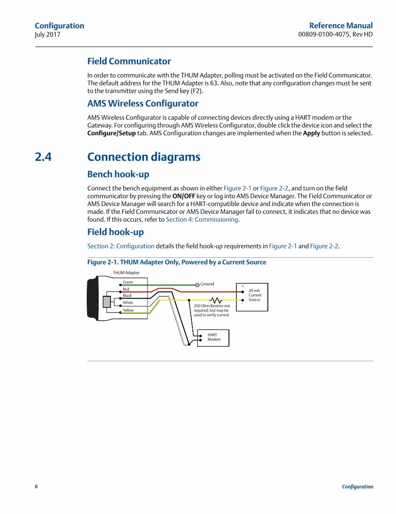
2.4 Connection diagramsBench hook-upConnect the bench equipment as shown in either Figure 2-1 or Figure 2-2, and turn on the field communicator by pressing the ON/OFF key or log into AMS Device Manager. The Field Communicator or AMS Device Manager will search for a HART-compatible device and indicate when the connection is made. If the Field Communicator or AMS Device Manager fail to connect, it indicates that no device was found. If this occurs, refer to Section 4: Commissioning.
Field hook-upSection 2: Configuration details the field hook-up requirements in Figure 2-1 and Figure 2-2.
Figure 2-1. THUM Adapter Only, Powered by a Current Source
Ground
-
20 mA Current Source
HARTModem
THUM Adapter
Green
Red
Black
White
Yellow
+
250 Ohm Resistor not required, but may be used to verify current
6 Configuration
Reference Manual 00809-0100-4075, Rev CB
ConfigurationJuly 2017
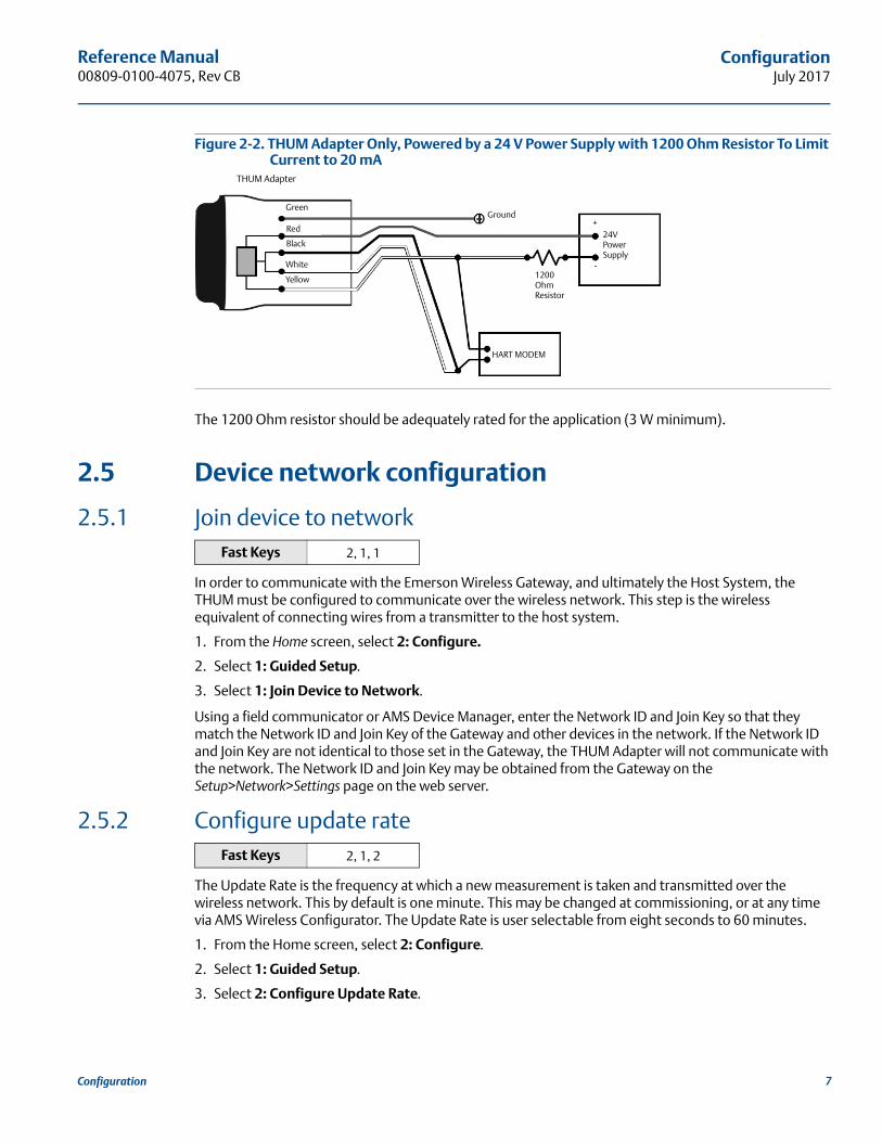
Figure 2-2. THUM Adapter Only, Powered by a 24 V Power Supply with 1200 Ohm Resistor To Limit Current to 20 mA
The 1200 Ohm resistor should be adequately rated for the application (3 W minimum).
2.5 Device network configuration
2.5.1 Join device to network
In order to communicate with the Emerson Wireless Gateway, and ultimately the Host System, the THUM must be configured to communicate over the wireless network. This step is the wireless equivalent of connecting wires from a transmitter to the host system.
1. From the Home screen, select 2: Configure.
2. Select 1: Guided Setup.
3. Select 1: Join Device to Network.
Using a field communicator or AMS Device Manager, enter the Network ID and Join Key so that they match the Network ID and Join Key of the Gateway and other devices in the network. If the Network ID and Join Key are not identical to those set in the Gateway, the THUM Adapter will not communicate with the network. The Network ID and Join Key may be obtained from the Gateway on the Setup>Network>Settings page on the web server.
2.5.2 Configure update rate
The Update Rate is the frequency at which a new measurement is taken and transmitted over the wireless network. This by default is one minute. This may be changed at commissioning, or at any time via AMS Wireless Configurator. The Update Rate is user selectable from eight seconds to 60 minutes.
1. From the Home screen, select 2: Configure.
2. Select 1: Guided Setup.
3. Select 2: Configure Update Rate.
Fast Keys 2, 1, 1
Fast Keys 2, 1, 2
THUM Adapter
Red
Black
White
Yellow
HART MODEM
Ground
1200 OhmResistor
Green
24V PowerSupply
+
-
7Configuration
Reference Manual00809-0100-4075, Rev HD
ConfigurationJuly 2017
2.5.3 Configure THUM Adapter long tag
The Long Tag is how the THUM Adapter will show up in the Gateway web interface. By setting this parameter to a unique value it will be easier to determine which THUM Adapter you are communicating with. One way to do this is to use the tag number of the wired device that the THUM adapter is connected to followed by THUM (HARTTAG-THUM).
1. From the Home screen, select 2: Configure.
2. Select 1: Manual Setup.
3. Select 2: Device Information tab.
4. Enter the Long Tag.
2.5.4 Wired device tagFor HART 5 devices the THUM Adapter uses the message field when reporting the HART tag to the Gateway. To ensure that you can identify the wired device in the Gateway make sure to write the tag information into the message field for all HART 5 devices. For HART 6 or newer devices the THUM Adapter reports the long tag as the HART tag to the Gateway.
Fast Keys 2, 2, 4, 2
8 Configuration
Reference Manual 00809-0100-4075, Rev CB
ConfigurationJuly 2017
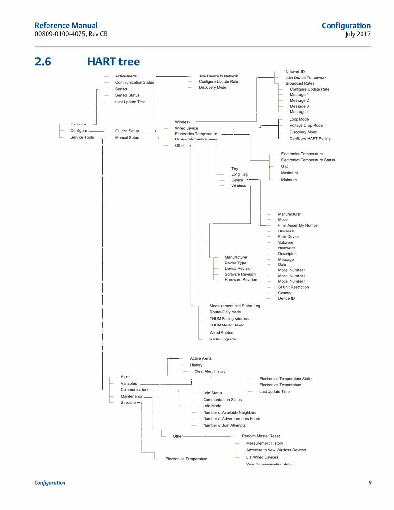
2.6 HART tree
9Configuration


Reference Manual 00809-0100-4075, Rev CB
MountingJuly 2017
Section 3 Mounting
Safety messages . . . . . . . . . . . . . . . . . . . . . . . . . . . . . . . . . . . . . . . . . . . . . . . . . . . . . . . . . . . . . . . . . . . . . . page 11Mounting . . . . . . . . . . . . . . . . . . . . . . . . . . . . . . . . . . . . . . . . . . . . . . . . . . . . . . . . . . . . . . . . . . . . . . . . . . . . page 12Loop current test . . . . . . . . . . . . . . . . . . . . . . . . . . . . . . . . . . . . . . . . . . . . . . . . . . . . . . . . . . . . . . . . . . . . . page 24
3.1 Safety messagesInstructions and procedures in this section may require special precautions to ensure the safety of the personnel performing the operations. Information that potentially raises safety issues is indicated by a warning symbol ( ). Please refer to the following safety messages before performing an operation preceded by this symbol.
Failure to follow these installation guidelines could result in death or serious injury. Only qualified personnel should perform the installation
Explosions could result in death or serious injury. Before connecting a field communicator in an explosive atmosphere, make sure that the instruments
are installed in accordance with intrinsically safe or non-incendive field wiring practices
Verify that the operating atmosphere of the transmitter is consistent with the appropriate hazardous locations certifications
Electrical shock could cause death or serious injury. Use extreme caution when making contact with the leads and terminals
This device complies with Part 15 of the FCC Rules. Operation is subject to the following conditions: This device may not cause harmful interference. This device must accept any interference received, including interference that may cause undesired operation.
This device must be installed to ensure a minimum antenna separation distance of 20 cm from all persons.
11Installation
Reference Manual00809-0100-4075, Rev CB
MountingJuly 2017
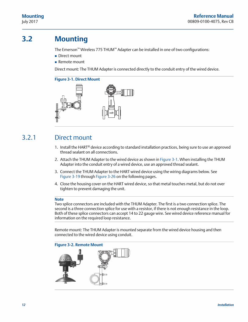
3.2 MountingThe Emerson™ Wireless 775 THUM™ Adapter can be installed in one of two configurations:
Direct mount
Remote mount
Direct mount: The THUM Adapter is connected directly to the conduit entry of the wired device.
Figure 3-1. Direct Mount
3.2.1 Direct mount1. Install the HART® device according to standard installation practices, being sure to use an approved
thread sealant on all connections.
2. Attach the THUM Adapter to the wired device as shown in Figure 3-1. When installing the THUM Adapter into the conduit entry of a wired device, use an approved thread sealant.
3. Connect the THUM Adapter to the HART wired device using the wiring diagrams below. See Figure 3-19 through Figure 3-26 on the following pages.
4. Close the housing cover on the HART wired device, so that metal touches metal, but do not over tighten to prevent damaging the unit.
NoteTwo splice connectors are included with the THUM Adapter. The first is a two connection splice. The second is a three connection splice for use with a resistor, if there is not enough resistance in the loop. Both of these splice connectors can accept 14 to 22 gauge wire. See wired device reference manual for information on the required loop resistance.
Remote mount: The THUM Adapter is mounted separate from the wired device housing and then connected to the wired device using conduit.
Figure 3-2. Remote Mount
12 Installation
Reference Manual 00809-0100-4075, Rev CB
MountingJuly 2017
3.2.2 Remote mount1. Install the HART device according to standard installation practices, being sure to use an approved
thread sealant on all connections.
2. The THUM Adapter should be mounted as shown in Figure 3-2 on page 12.
3. Connect the THUM Adapter to the wired device using standard practices. Wire running from the THUM Adapter to the wired device must be shielded or in conduit.
4. Ground the Remote Mount Kit per local practices.
5. Connect the THUM Adapter to the HART wired device using the wiring diagrams below. See Figure 3-19 through Figure 3-26 on the following pages.
6. Close the housing cover on the HART wired device, so that metal touches metal, but do not over tighten to prevent damaging the unit.
NoteTwo splice connectors are included with the THUM Adapter. The first is a two connection splice. The second is a three connection splice for use with a resistor, if there is not enough resistance in the loop. Both of these splice connectors can accept 14 to 22 gauge wire. See wired device reference manual for information on the required loop resistance.
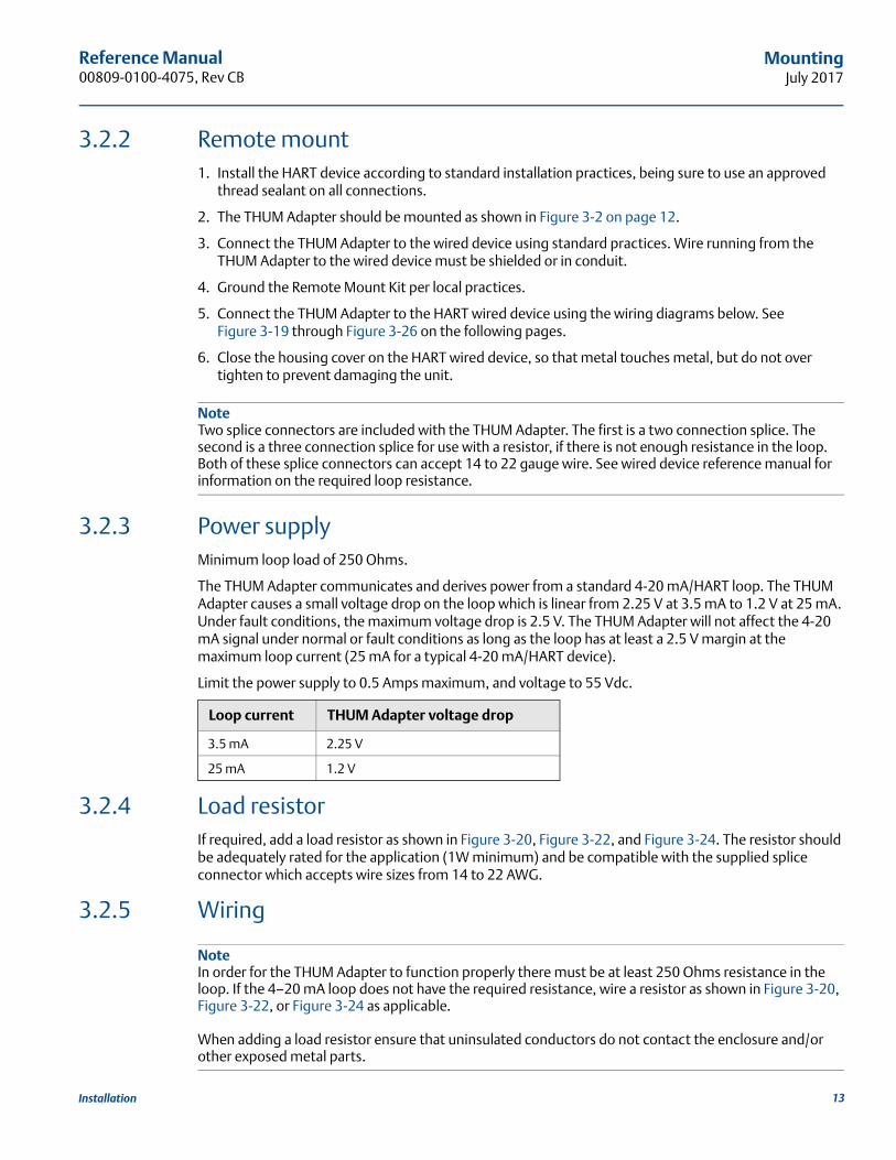
3.2.3 Power supplyMinimum loop load of 250 Ohms.
The THUM Adapter communicates and derives power from a standard 4-20 mA/HART loop. The THUM Adapter causes a small voltage drop on the loop which is linear from 2.25 V at 3.5 mA to 1.2 V at 25 mA. Under fault conditions, the maximum voltage drop is 2.5 V. The THUM Adapter will not affect the 4-20 mA signal under normal or fault conditions as long as the loop has at least a 2.5 V margin at the maximum loop current (25 mA for a typical 4-20 mA/HART device).
Limit the power supply to 0.5 Amps maximum, and voltage to 55 Vdc.
3.2.4 Load resistorIf required, add a load resistor as shown in Figure 3-20, Figure 3-22, and Figure 3-24. The resistor should be adequately rated for the application (1W minimum) and be compatible with the supplied splice connector which accepts wire sizes from 14 to 22 AWG.
3.2.5 Wiring
NoteIn order for the THUM Adapter to function properly there must be at least 250 Ohms resistance in the loop. If the 4–20 mA loop does not have the required resistance, wire a resistor as shown in Figure 3-20, Figure 3-22, or Figure 3-24 as applicable.
When adding a load resistor ensure that uninsulated conductors do not contact the enclosure and/or other exposed metal parts.
Loop current THUM Adapter voltage drop
3.5 mA 2.25 V
25 mA 1.2 V
13Installation
Reference Manual00809-0100-4075, Rev CB
MountingJuly 2017
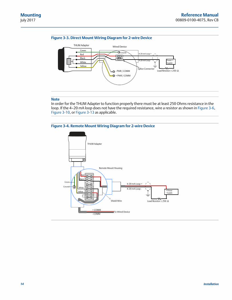
Figure 3-3. Direct Mount Wiring Diagram for 2-wire Device
NoteIn order for the THUM Adapter to function properly there must be at least 250 Ohms resistance in the loop. If the 4–20 mA loop does not have the required resistance, wire a resistor as shown in Figure 3-6, Figure 3-10, or Figure 3-13 as applicable.
Figure 3-4. Remote Mount Wiring Diagram for 2-wire Device
Splice Connector
Wired Device
4-20 mA Loop -
4-20 mA Loop +Ground
- PWR / COMM
+ PWR / COMM
THUM Adapter
Green
Red
Black
White
Yellow
Load Resistor ≥ 250 Ω
Power + Supply-
Remote Mount Housing
4-20 mA Loop -
4-20 mA Loop +Ground
+ COMM
- COMM
THUM Adapter
Green
Red
Black
White
Yellow
To Wired Device
Shield Wire Load Resistor ≥ 250 Ω
+ Power - Supply
14 Installation
15
Reference Manual 00809-0100-4075, Rev CB
MountingJuly 2017
Ins
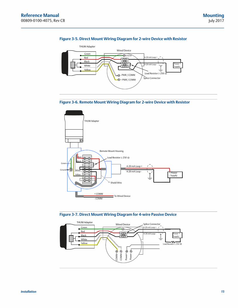
tallationFigure 3-5. Direct Mount Wiring Diagram for 2-wire Device with Resistor
Figure 3-6. Remote Mount Wiring Diagram for 2-wire Device with Resistor
Figure 3-7. Direct Mount Wiring Diagram for 4-wire Passive Device
Splice Connector
Wired Device
4-20 mA Loop -
4-20 mA Loop +Ground
- PWR / COMM
+ PWR / COMM
THUM Adapter
Green
Red
Black
White
Yellow
Power + Supply-
Load Resistor ≥ 250 Ω
Remote Mount Housing
4-20 mA Loop -
4-20 mA Loop +Ground
+ COMM
- COMM
THUM Adapter
Green
Red
Black
White
Yellow
To Wired Device
Shield Wire
Load Resistor ≥ 250 Ω
+ Power - Supply
Splice ConnectorWired Device
4-20 mA Loop -
4-20 mA Loop +Ground
THUM Adapter
Green
Red
Black
White
Yellow
Pow
er+
Pow
er-
COM
M+
CO
MM
-
Power + Supply-
Load Resistor ≥ 250 Ω
Reference Manual00809-0100-4075, Rev CB
MountingJuly 2017
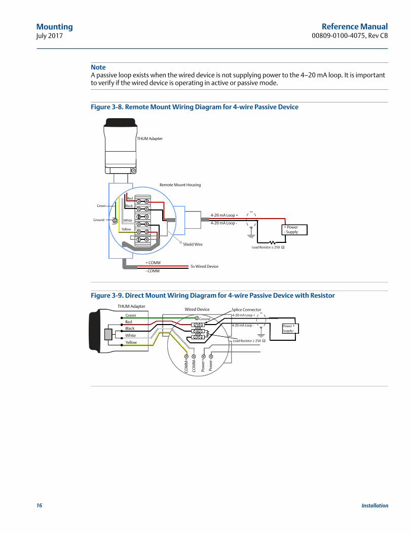
NoteA passive loop exists when the wired device is not supplying power to the 4–20 mA loop. It is important to verify if the wired device is operating in active or passive mode.
Figure 3-8. Remote Mount Wiring Diagram for 4-wire Passive Device
Figure 3-9. Direct Mount Wiring Diagram for 4-wire Passive Device with Resistor
Remote Mount Housing
4-20 mA Loop -
4-20 mA Loop +Ground
+ COMM
- COMM
THUM Adapter
Green
Red
Black
White
Yellow
To Wired Device
Shield WireLoad Resistor ≥ 250 Ω
+ Power - Supply
Splice ConnectorWired Device
4-20 mA Loop -
4-20 mA Loop +Ground
THUM Adapter
Green
Red
Black
White
Yellow
Pow
er+
Pow
er-
COM
M+
CO
MM
-
Load Resistor ≥ 250 Ω
Power + Supply-
16 Installation
Reference Manual 00809-0100-4075, Rev CB
MountingJuly 2017
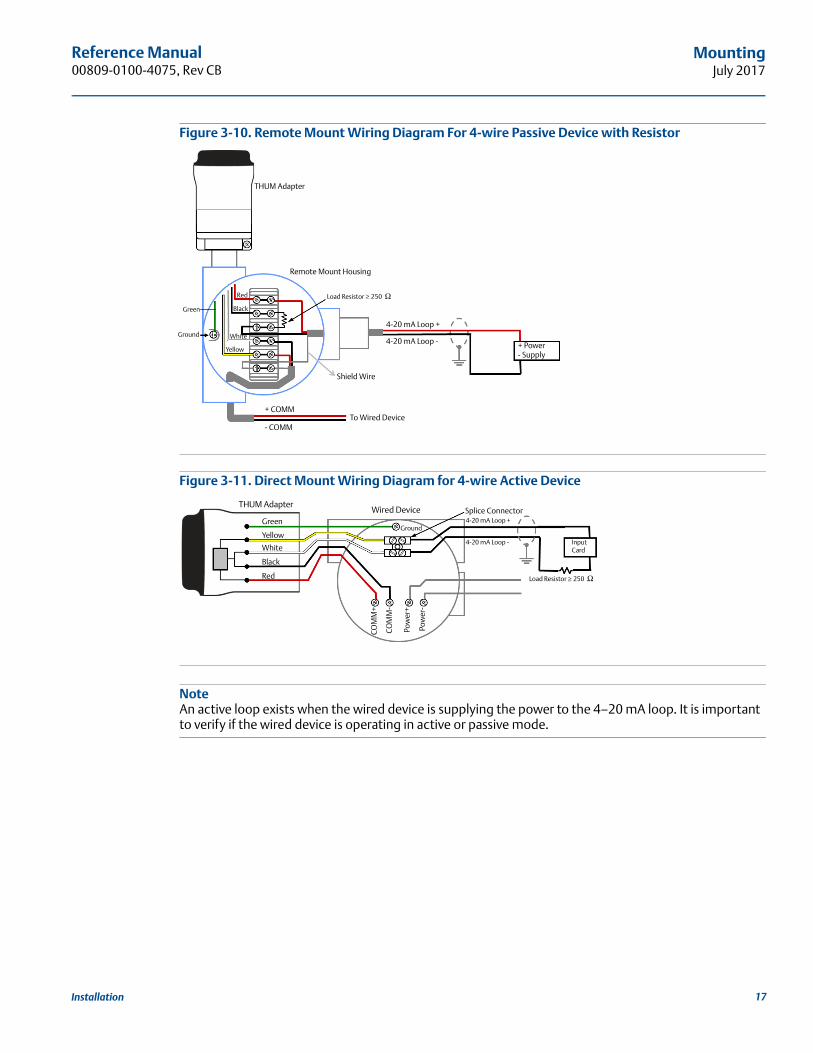
Figure 3-10. Remote Mount Wiring Diagram For 4-wire Passive Device with Resistor
Figure 3-11. Direct Mount Wiring Diagram for 4-wire Active Device
NoteAn active loop exists when the wired device is supplying the power to the 4–20 mA loop. It is important to verify if the wired device is operating in active or passive mode.
Remote Mount Housing
4-20 mA Loop -
4-20 mA Loop +Ground
+ COMM
- COMM
THUM Adapter
Green
Red
Black
White
Yellow
To Wired Device
Shield Wire
+ Power - Supply
Load Resistor ≥ 250 Ω
Splice ConnectorWired Device
4-20 mA Loop -
4-20 mA Loop +Ground
THUM Adapter
Green
Yellow
White
Black
Red
Input Card
Pow
er+
Pow
er-
COM
M+
CO
MM
-
Load Resistor ≥ 250 Ω
17Installation
Reference Manual00809-0100-4075, Rev CB
MountingJuly 2017
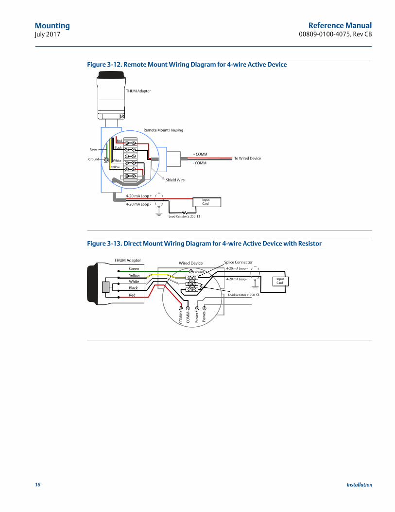
Figure 3-12. Remote Mount Wiring Diagram for 4-wire Active Device
Figure 3-13. Direct Mount Wiring Diagram for 4-wire Active Device with Resistor
Remote Mount Housing
4-20 mA Loop -
4-20 mA Loop +
Ground+ COMM
- COMM
THUM Adapter
Green
Red
Black
White
Yellow
To Wired Device
Shield Wire
Load Resistor ≥ 250 Ω
Input Card
Splice ConnectorWired Device
Ground
THUM Adapter
Green
Yellow
White
Black
Red
4-20 mA Loop -
4-20 mA Loop +
Load Resistor ≥ 250 Ω
Input Card
Pow
er+
Pow
er-
COM
M+
CO
MM
-
18 Installation
Reference Manual 00809-0100-4075, Rev CB
MountingJuly 2017
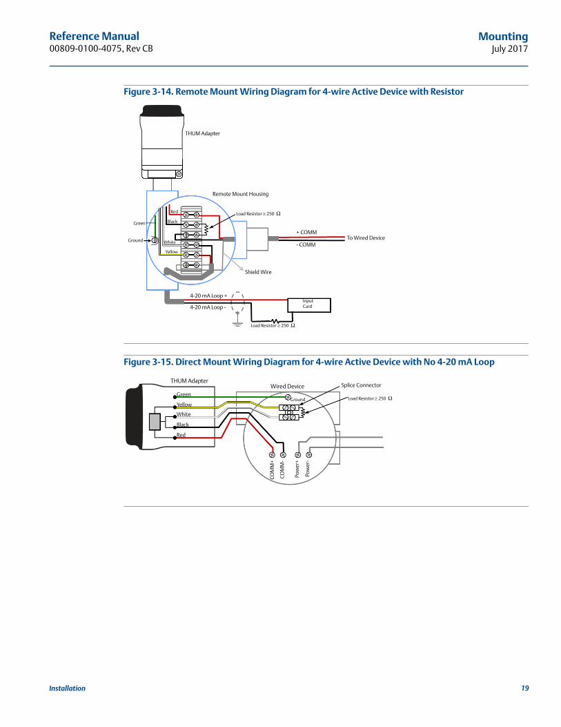
Figure 3-14. Remote Mount Wiring Diagram for 4-wire Active Device with Resistor
Figure 3-15. Direct Mount Wiring Diagram for 4-wire Active Device with No 4-20 mA Loop
Remote Mount Housing
4-20 mA Loop -
4-20 mA Loop +
Ground
+ COMM
- COMM
THUM Adapter
Green
White
Black
Red
To Wired Device
Yellow
Shield Wire
Load Resistor ≥ 250 Ω
Load Resistor ≥ 250 Ω
Input Card
Splice ConnectorWired Device
Ground
THUM Adapter
Green
Yellow
White
Black
Red
Load Resistor ≥ 250 Ω
Pow
er+
Pow
er-
COM
M+
COM
M-
19Installation
Reference Manual00809-0100-4075, Rev CB
MountingJuly 2017
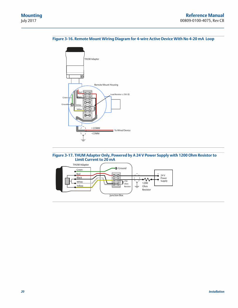
Figure 3-16. Remote Mount Wiring Diagram for 4-wire Active Device With No 4-20 mA Loop
Figure 3-17. THUM Adapter Only, Powered by A 24 V Power Supply with 1200 Ohm Resistor to Limit Current to 20 mA
Remote Mount Housing
Ground
+ COMM
- COMM
THUM Adapter
Green
White
Black
Red
To Wired Device
Yellow
Load Resistor ≥ 250 Ω
Junction Box
THUM Adapter
250 Ohm Resistor
Ground
1200 Ohm Resistor
-
24 VPower Supply
+
Green
Red
Black
White
Yellow
20 Installation
Reference Manual 00809-0100-4075, Rev CB
MountingJuly 2017
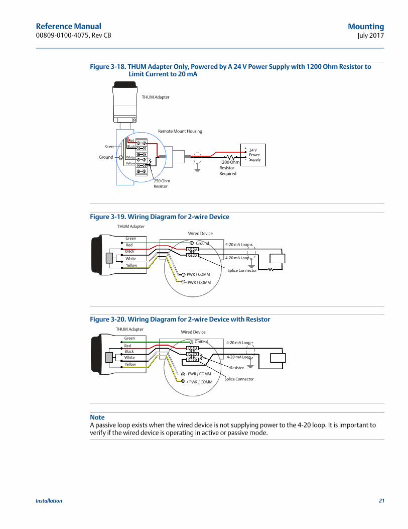
Figure 3-18. THUM Adapter Only, Powered by A 24 V Power Supply with 1200 Ohm Resistor to Limit Current to 20 mA
Figure 3-19. Wiring Diagram for 2-wire Device
Figure 3-20. Wiring Diagram for 2-wire Device with Resistor
NoteA passive loop exists when the wired device is not supplying power to the 4-20 loop. It is important to verify if the wired device is operating in active or passive mode.
Remote Mount Housing
THUM Adapter
250 OhmResistor
Ground1200 Ohm ResistorRequired
-
24 VPower Supply
+Green
White
Black
Red
Yellow
Splice Connector
Wired Device
4-20 mA Loop -
4-20 mA Loop +Ground
- PWR / COMM
+ PWR / COMM
THUM Adapter
Green
Red
Black
White
Yellow
Splice Connector
Wired Device
4-20 mA Loop -
4-20 mA Loop +Ground
- PWR / COMM
+ PWR / COMM
THUM Adapter
Green
RedBlack
White
YellowResistor
21Installation
Reference Manual00809-0100-4075, Rev CB
MountingJuly 2017
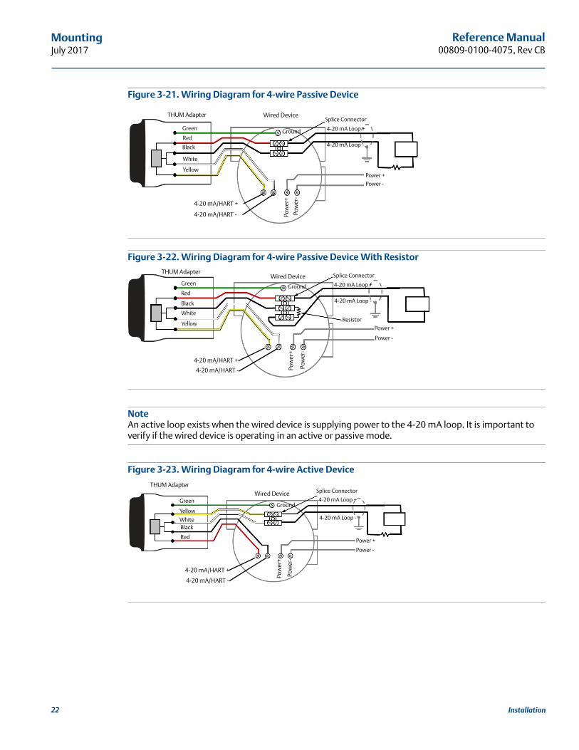
Figure 3-21. Wiring Diagram for 4-wire Passive Device
Figure 3-22. Wiring Diagram for 4-wire Passive Device With Resistor
NoteAn active loop exists when the wired device is supplying power to the 4-20 mA loop. It is important to verify if the wired device is operating in an active or passive mode.
Figure 3-23. Wiring Diagram for 4-wire Active Device
Splice ConnectorWired Device
4-20 mA Loop -
4-20 mA Loop +Ground
Power +
Power -
THUM Adapter
Green
Red
Black
White
Yellow
Pow
er+
Pow
er-
4-20 mA/HART -
4-20 mA/HART +
Splice ConnectorWired Device
4-20 mA Loop -
4-20 mA Loop +Ground
Power +
Power -
THUM Adapter
Green
Red
Black
White
Yellow
Pow
er+
Pow
er-
4-20 mA/HART -
4-20 mA/HART +
Resistor
Splice ConnectorWired Device
4-20 mA Loop -
4-20 mA Loop +Ground
Power +
Power -
THUM Adapter
Green
Yellow
WhiteBlack
Red
Pow
er+
Pow
er-
4-20 mA/HART -
4-20 mA/HART +
22 Installation
Reference Manual 00809-0100-4075, Rev CB
MountingJuly 2017
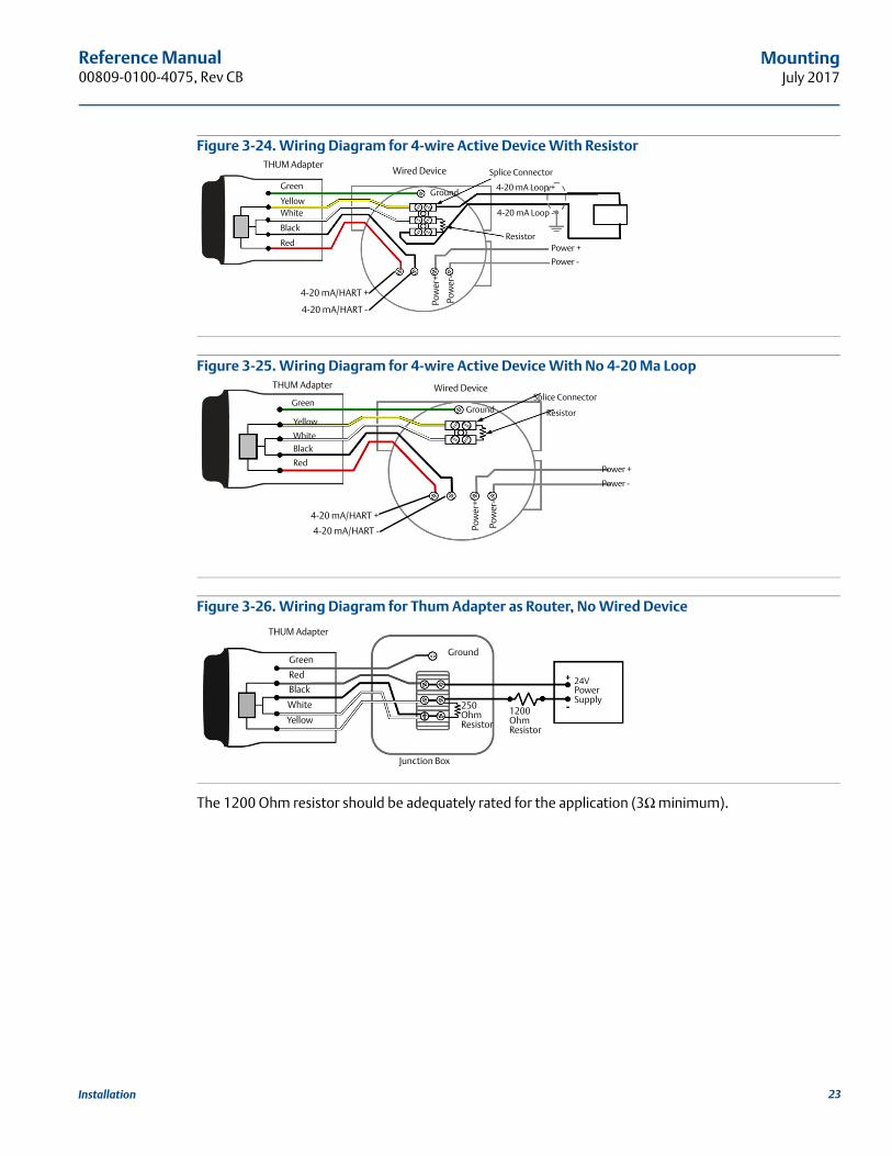
Figure 3-24. Wiring Diagram for 4-wire Active Device With Resistor
Figure 3-25. Wiring Diagram for 4-wire Active Device With No 4-20 Ma Loop
Figure 3-26. Wiring Diagram for Thum Adapter as Router, No Wired Device
The 1200 Ohm resistor should be adequately rated for the application (3Ω minimum).
Splice ConnectorWired Device
4-20 mA Loop -
4-20 mA Loop +Ground
Power +
Power -
THUM Adapter
Green
YellowWhite
Black
Red
Pow
er+
Pow
er-
4-20 mA/HART -
4-20 mA/HART +
Resistor
Splice ConnectorWired Device
Ground
Power +
Power -
THUM Adapter
Green
Yellow
WhiteBlack
RedPo
wer
+
Pow
er-
4-20 mA/HART -
4-20 mA/HART +
Resistor
THUM Adapter
Red
Green
Black
White
Ground
250 OhmResistor
1200 Ohm Resistor
Yellow
24VPowerSupply
Junction Box
23Installation
Reference Manual00809-0100-4075, Rev CB
MountingJuly 2017
3.3 Loop current testTo verify that the THUM Adapter will work under all conditions, a loop current test should be performed. This test will exercise the loop under the highest possible voltage drop conditions.
1. Place loop in manual control.
2. Drive loop to high alarm level. For details, see wired device instruction manual.
When the THUM Adapter is connected to a valve, this will need to be done at the current source and not from the valve.
When the THUM Adapter is connected to a transmitter, this will need to be performed at the transmitter.
3. Place the THUM Adapter into fixed voltage drop mode.
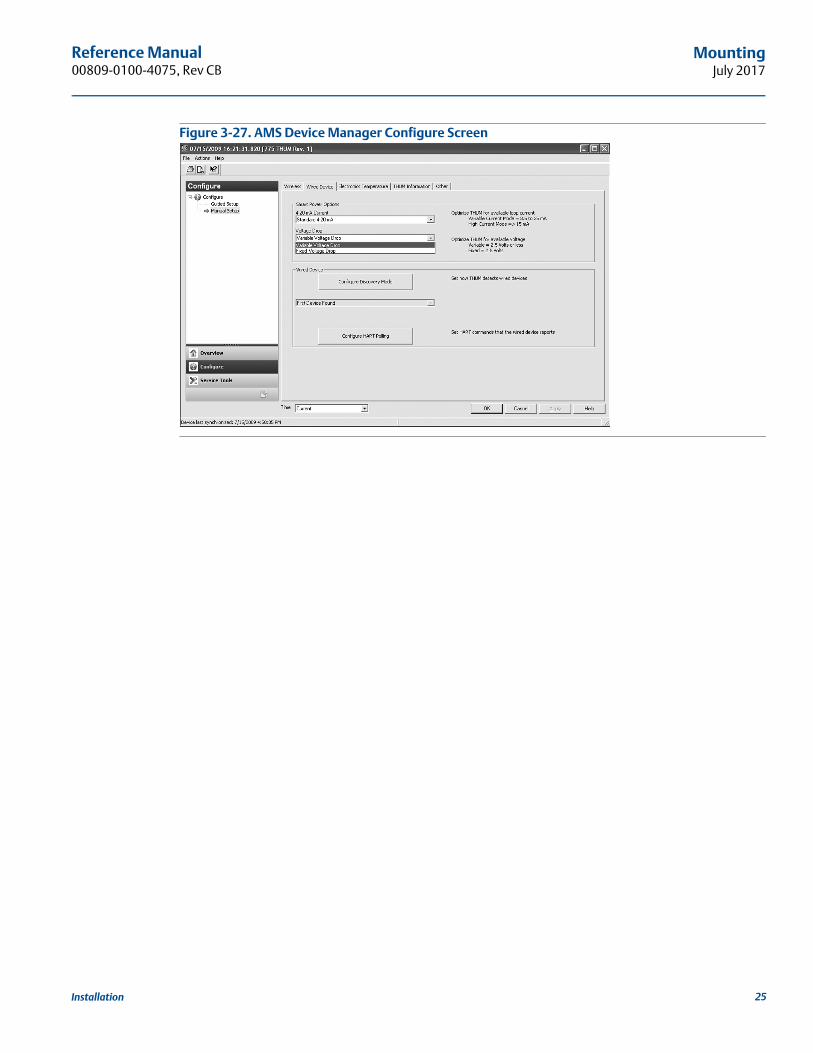
AMS Device Manager Right click on the THUM Adapter and select Configure. When the menu opens, select Manual Setup from the window on the left and select the Wired Device tab on the top. Make sure that the Time drop down menu at the bottom of the page has Current selected. Under the Voltage Drop drop down menu in the Smart Power Options box, select Fixed Voltage Drop. Hit the Apply button to make any changes. See Figure 3-27 on page 25.
Field CommunicatorWhen communicating to the THUM Adapter select: Configure > Manual setup > Wired Device > Voltage Drop Mode. In the method select Fixed Voltage Drop.
4. Verify the current on the loop reaches the high alarm levels.
5. Place the THUM Adapter into variable voltage drop mode.
AMS Device Manager Right click on the THUM Adapter and select Configure. When the menu opens, select Manual Setup from the window on the left and select the Wired Device tab on the top. Make sure the Time drop down menu at the bottom of the page has Current selected. Under the Voltage Drop drop down menu in the Smart Power Options box, select Variable Voltage Drop. Hit the Apply button to make any changes. See Figure 3-27.
Field CommunicatorWhen communicating to the THUM Adapter, select: Configure > Manual setup > Wired Device > Voltage Drop Mode. In the method select Variable Voltage Drop.
6. Remove loop from high alarm value.
Function Key sequence Menu items
Voltage Drop 2,2,2,2 Voltage Drop
Function Key sequence Menu items
Voltage Drop 2,2,2,2 Voltage Drop
24 Installation
Reference Manual 00809-0100-4075, Rev CB
MountingJuly 2017
Figure 3-27. AMS Device Manager Configure Screen
25Installation

26
Reference Manual00809-0100-4075, Rev CB
MountingJuly 2017
Installation
Reference Manual 00809-0100-4075, Rev CB
CommissioningJuly 2017
Section 4 Commissioning
Safety messages . . . . . . . . . . . . . . . . . . . . . . . . . . . . . . . . . . . . . . . . . . . . . . . . . . . . . . . . . . . . . . . . . . . . . . page 27Device network configuration . . . . . . . . . . . . . . . . . . . . . . . . . . . . . . . . . . . . . . . . . . . . . . . . . . . . . . . . . . page 27
4.1 Safety messagesInstructions and procedures in this section may require special precautions to ensure the safety of the personnel performing the operations. Information that potentially raises safety issues is indicated by a warning symbol ( ). Please refer to the following safety messages before performing an operation preceded by this symbol.
4.2 Device network configurationIn order to communicate with the Emerson™ Wireless Gateway, and ultimately the Information System, the transmitter must be configured to communicate with the wireless network. This step is the wireless equivalent of connecting wires from a transmitter to the information system. Using a Field Communicator or AMS Device Manager, enter the Network ID and Join Key so that they match the Network ID and Join Key of the Gateway and other devices in the network. If the Network ID and Join Key are not identical, the Emerson Wireless 775 THUM™ Adapter will not communicate with the network. The Network ID and Join Key may be obtained from the Gateway on the Setup>Network>Settings page on the web server, shown in Figure 4-1.
Failure to follow these installation guidelines could result in death or serious injury. Only qualified personnel should perform the installation.
Explosions could result in death or serious injury. Before connecting a Field Communicator in an explosive atmosphere, make sure that the
instruments are installed in accordance with intrinsically safe or non-incendive field wiring practices.
Verify that the operating atmosphere of the transmitter is consistent with the appropriate hazardous locations certifications.
Electrical shock could cause death or serious injury. Use extreme caution when making contact with the leads and terminals.
This device complies with Part 15 of the FCC Rules. Operation is subject to the following conditions: This device may not cause harmful interference. This device must accept any interference received, including interference that may cause undesired operation.
This device must be installed to ensure a minimum antenna separation distance of 20 cm from all persons.
27Commissioning
Reference Manual00809-0100-4075, Rev CB
CommissioningJuly 2017
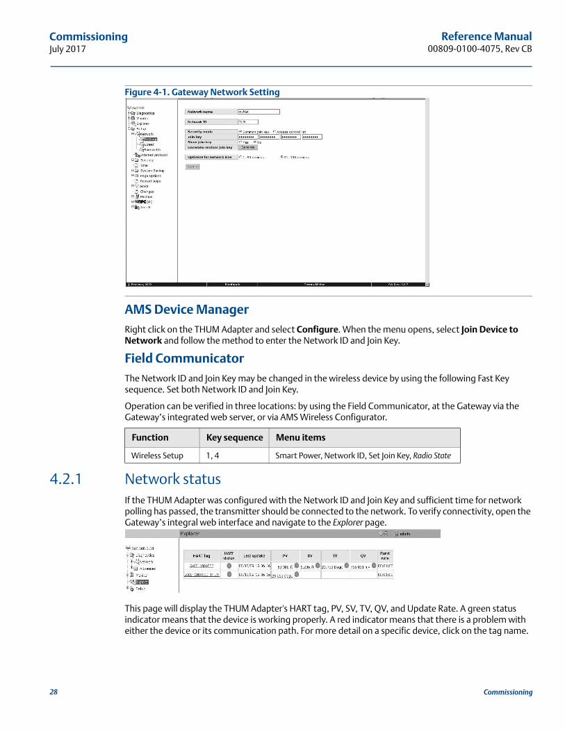
Figure 4-1. Gateway Network Setting
AMS Device ManagerRight click on the THUM Adapter and select Configure. When the menu opens, select Join Device to Network and follow the method to enter the Network ID and Join Key.
Field CommunicatorThe Network ID and Join Key may be changed in the wireless device by using the following Fast Key sequence. Set both Network ID and Join Key.
Operation can be verified in three locations: by using the Field Communicator, at the Gateway via the Gateway’s integrated web server, or via AMS Wireless Configurator.
4.2.1 Network statusIf the THUM Adapter was configured with the Network ID and Join Key and sufficient time for network polling has passed, the transmitter should be connected to the network. To verify connectivity, open the Gateway’s integral web interface and navigate to the Explorer page.
This page will display the THUM Adapter's HART tag, PV, SV, TV, QV, and Update Rate. A green status indicator means that the device is working properly. A red indicator means that there is a problem with either the device or its communication path. For more detail on a specific device, click on the tag name.
Function Key sequence Menu items
Wireless Setup 1, 4 Smart Power, Network ID, Set Join Key, Radio State
28 Commissioning
Reference Manual 00809-0100-4075, Rev CB
CommissioningJuly 2017
4.2.2 Verify operationOperation can be verified in three locations: by using the Field Communicator, at the Gateway via the Gateway’s integrated web server, or via AMS Wireless Configurator.
Field CommunicatorIn order for the THUM Adapter to communicate with a Field Communicator, a THUM Adapter DD is required. The Field Communicator must be put into a polling mode using the THUM adapter address of 63. Connect the Field Communicator to the wired device. The Field Communicator should find both the THUM Adapter and the wired device.
GatewayIf the THUM Adapter was configured with the Network ID and Join Key, and sufficient time has passed for network polling, the transmitter will be connected to the network. To verify device operation and connection to the network with the Gateway’s integrated web server, open the Gateway’s integral web interface and navigate to the Explorer page.
NoteIt may take several minutes for the device to join the network.
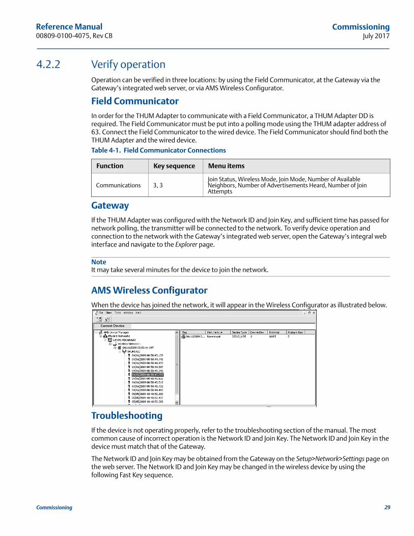
AMS Wireless ConfiguratorWhen the device has joined the network, it will appear in the Wireless Configurator as illustrated below.
TroubleshootingIf the device is not operating properly, refer to the troubleshooting section of the manual. The most common cause of incorrect operation is the Network ID and Join Key. The Network ID and Join Key in the device must match that of the Gateway.
The Network ID and Join Key may be obtained from the Gateway on the Setup>Network>Settings page on the web server. The Network ID and Join Key may be changed in the wireless device by using the following Fast Key sequence.
Table 4-1. Field Communicator Connections
Function Key sequence Menu items
Communications 3, 3Join Status, Wireless Mode, Join Mode, Number of Available Neighbors, Number of Advertisements Heard, Number of Join Attempts
29Commissioning
Reference Manual00809-0100-4075, Rev CB
CommissioningJuly 2017
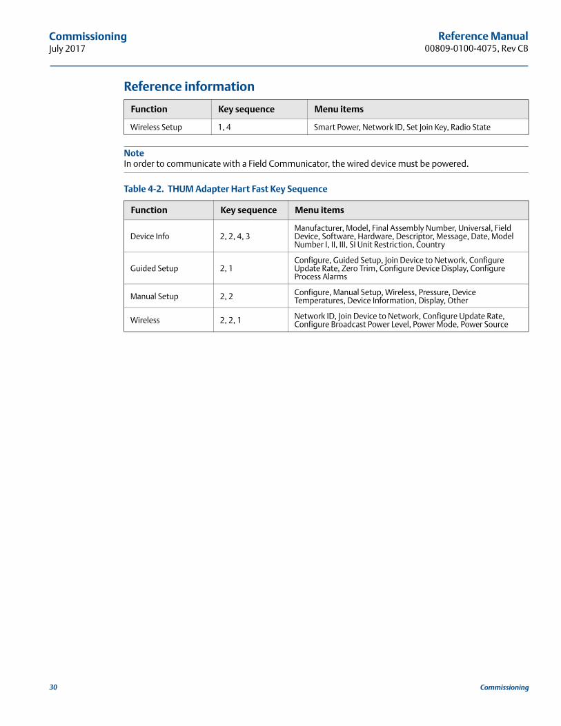
Reference information
NoteIn order to communicate with a Field Communicator, the wired device must be powered.
Function Key sequence Menu items
Wireless Setup 1, 4 Smart Power, Network ID, Set Join Key, Radio State
Table 4-2. THUM Adapter Hart Fast Key Sequence
Function Key sequence Menu items
Device Info 2, 2, 4, 3Manufacturer, Model, Final Assembly Number, Universal, Field Device, Software, Hardware, Descriptor, Message, Date, Model Number I, II, III, SI Unit Restriction, Country
Guided Setup 2, 1Configure, Guided Setup, Join Device to Network, Configure Update Rate, Zero Trim, Configure Device Display, Configure Process Alarms
Manual Setup 2, 2 Configure, Manual Setup, Wireless, Pressure, Device Temperatures, Device Information, Display, Other
Wireless 2, 2, 1 Network ID, Join Device to Network, Configure Update Rate, Configure Broadcast Power Level, Power Mode, Power Source
30 Commissioning
Reference Manual 00809-0100-4075, Rev CB
Operation and MaintenanceJuly 2017
Section 5 Operation and maintenance
Safety messages . . . . . . . . . . . . . . . . . . . . . . . . . . . . . . . . . . . . . . . . . . . . . . . . . . . . . . . . . . . . . . . . . . . . . . page 31Startup sequence . . . . . . . . . . . . . . . . . . . . . . . . . . . . . . . . . . . . . . . . . . . . . . . . . . . . . . . . . . . . . . . . . . . . . page 31Advanced setup . . . . . . . . . . . . . . . . . . . . . . . . . . . . . . . . . . . . . . . . . . . . . . . . . . . . . . . . . . . . . . . . . . . . . . page 32
5.1 Safety messagesInstructions and procedures in this section may require special precautions to ensure the safety of the personnel performing the operations. Information that potentially raises safety issues is indicated by a warning symbol ( ). Please refer to the following safety messages before performing an operation preceded by this symbol.
5.2 Startup sequenceBecause the Emerson™ Wireless 775 THUM™ Adapter is a power scavenging device, different capabilities are available at different times after startup. Configuration is available immediately after startup and includes Update Rate and Discovery method. All network settings including Network ID, Join Key can not be set until the radio is completely initialized. This may take up to three minutes after startup.
After this amount of time has passed, the THUM adapter will start to join the network. Time to join the network depends on network size and number of devices and if active advertising is turned on in the Gateway. After sufficient time to join has passed go to the Explorer page on the Emerson Wireless Gateway to see if the THUM Adapter has joined.
Failure to follow these installation guidelines could result in death or serious injury. Only qualified personnel should perform the installation.
Explosions could result in death or serious injury. Before connecting a Field Communicator in an explosive atmosphere, make sure that the
instruments are installed in accordance with intrinsically safe or non-incendive field wiring practices.
Verify that the operating atmosphere of the transmitter is consistent with the appropriate hazardous locations certifications.
Electrical shock could cause death or serious injury. Use extreme caution when making contact with the leads and terminals.
This device complies with Part 15 of the FCC Rules. Operation is subject to the following conditions: This device may not cause harmful interference. This device must accept any interference received, including interference that may cause undesired operation.
This device must be installed to ensure a minimum antenna separation distance of 20 cm from all persons.
31Operation and Maintenance
Reference Manual00809-0100-4075, Rev CB
Operation and MaintenanceJuly 2017
5.3 Advanced setup
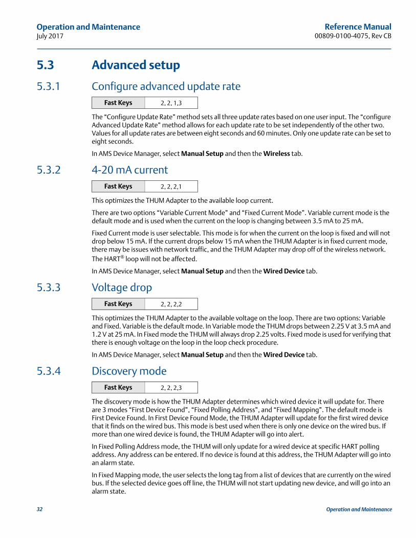
5.3.1 Configure advanced update rate
The “Configure Update Rate” method sets all three update rates based on one user input. The “configure Advanced Update Rate” method allows for each update rate to be set independently of the other two. Values for all update rates are between eight seconds and 60 minutes. Only one update rate can be set to eight seconds.
In AMS Device Manager, select Manual Setup and then the Wireless tab.
5.3.2 4-20 mA current
This optimizes the THUM Adapter to the available loop current.
There are two options “Variable Current Mode” and “Fixed Current Mode”. Variable current mode is the default mode and is used when the current on the loop is changing between 3.5 mA to 25 mA.
Fixed Current mode is user selectable. This mode is for when the current on the loop is fixed and will not drop below 15 mA. If the current drops below 15 mA when the THUM Adapter is in fixed current mode, there may be issues with network traffic, and the THUM Adapter may drop off of the wireless network. The HART® loop will not be affected.
In AMS Device Manager, select Manual Setup and then the Wired Device tab.
5.3.3 Voltage drop
This optimizes the THUM Adapter to the available voltage on the loop. There are two options: Variable and Fixed. Variable is the default mode. In Variable mode the THUM drops between 2.25 V at 3.5 mA and 1.2 V at 25 mA. In Fixed mode the THUM will always drop 2.25 volts. Fixed mode is used for verifying that there is enough voltage on the loop in the loop check procedure.
In AMS Device Manager, select Manual Setup and then the Wired Device tab.
5.3.4 Discovery mode
The discovery mode is how the THUM Adapter determines which wired device it will update for. There are 3 modes “First Device Found”, “Fixed Polling Address”, and “Fixed Mapping”. The default mode is First Device Found. In First Device Found Mode, the THUM Adapter will update for the first wired device that it finds on the wired bus. This mode is best used when there is only one device on the wired bus. If more than one wired device is found, the THUM Adapter will go into alert.
In Fixed Polling Address mode, the THUM will only update for a wired device at specific HART polling address. Any address can be entered. If no device is found at this address, the THUM Adapter will go into an alarm state.
In Fixed Mapping mode, the user selects the long tag from a list of devices that are currently on the wired bus. If the selected device goes off line, the THUM will not start updating new device, and will go into an alarm state.
Fast Keys 2, 2, 1,3
Fast Keys 2, 2, 2,1
Fast Keys 2, 2, 2,2
Fast Keys 2, 2, 2,3
32 Operation and Maintenance
Reference Manual 00809-0100-4075, Rev CB
Operation and MaintenanceJuly 2017
In AMS Device Manager, select Manual Setup and then the Wired Device tab.
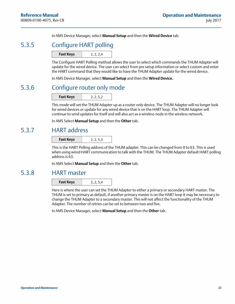
5.3.5 Configure HART polling
The Configure HART Polling method allows the user to select which commands the THUM Adapter will update for the wired device. The user can select from pre setup information or select custom and enter the HART command that they would like to have the THUM Adapter update for the wired device.
In AMS Device Manager, select Manual Setup and then the Wired Device.
5.3.6 Configure router only mode
This mode will set the THUM Adapter up as a router only device. The THUM Adapter will no longer look for wired devices or update for any wired device that is on the HART loop. The THUM Adapter will continue to send updates for itself and will also act as a wireless node in the wireless network.
In AMS Select Manual Setup and then the Other tab.
5.3.7 HART address
This is the HART Polling address of the THUM adapter. This can be changed from 0 to 63. This is used when using wired HART communication to talk with the THUM. The THUM Adapter default HART polling address is 63.
In AMS Select Manual Setup and then the Other tab.
5.3.8 HART master
Here is where the user can set the THUM Adapter to either a primary or secondary HART master. The THUM is set to primary as default, if another primary master is on the HART loop it may be necessary to change the THUM Adapter to a secondary master. This will not affect the functionality of the THUM Adapter. The number of retries can be set to between two and five.
In AMS Device Manager, select Manual Setup and then the Other tab.
Fast Keys 2, 2, 2,4
Fast Keys 2, 2, 5,2
Fast Keys 2, 2, 5,3
Fast Keys 2, 2, 5,4
33Operation and Maintenance


Reference Manual 00809-0100-4075, Rev CB
TroubleshootingJuly 2017
Section 6 Troubleshooting
Overview . . . . . . . . . . . . . . . . . . . . . . . . . . . . . . . . . . . . . . . . . . . . . . . . . . . . . . . . . . . . . . . . . . . . . . . . . . . . page 35Troubleshooting Recommended Actions . . . . . . . . . . . . . . . . . . . . . . . . . . . . . . . . . . . . . . . . . . . . . . . . page 36Service support . . . . . . . . . . . . . . . . . . . . . . . . . . . . . . . . . . . . . . . . . . . . . . . . . . . . . . . . . . . . . . . . . . . . . . . page 37
6.1 OverviewTable 6-1 on page 36 provides summarized maintenance and troubleshooting suggestions for the most common operating problems.
If you suspect malfunction despite the absence of any diagnostic messages on the Field Communicator display, follow the procedures described here to verify that transmitter hardware and process connections are in good working order. Always deal with the most likely checkpoints first.
Failure to follow these installation guidelines could result in death or serious injury. Only qualified personnel should perform the installation.
Explosions could result in death or serious injury. Before connecting a Field Communicator in an explosive atmosphere, make sure that the
instruments are installed in accordance with intrinsically safe or non-incendive field wiring practices.
Verify that the operating atmosphere of the transmitter is consistent with the appropriate hazardous locations certifications.
Electrical shock could cause death or serious injury. Use extreme caution when making contact with the leads and terminals.
This device complies with Part 15 of the FCC Rules. Operation is subject to the following conditions: This device may not cause harmful interference. This device must accept any interference received, including interference that may cause undesired operation.
This device must be installed to ensure a minimum antenna separation distance of 20 cm from all persons.
35Troubleshooting
Reference Manual00809-0100-4075, Rev CB
TroubleshootingJuly 2017
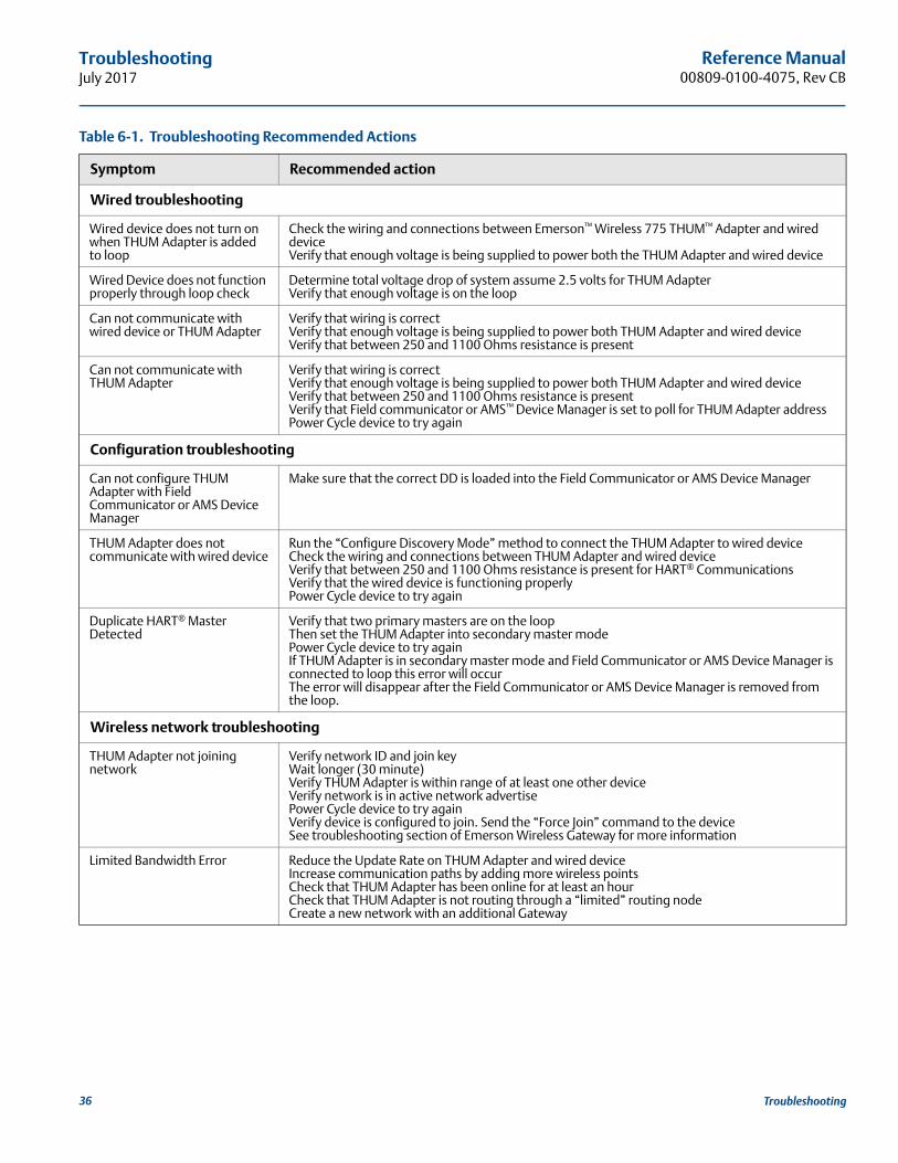
Table 6-1. Troubleshooting Recommended Actions
Symptom Recommended action
Wired troubleshooting
Wired device does not turn on when THUM Adapter is added to loop
Check the wiring and connections between Emerson™ Wireless 775 THUM™ Adapter and wired deviceVerify that enough voltage is being supplied to power both the THUM Adapter and wired device
Wired Device does not function properly through loop check
Determine total voltage drop of system assume 2.5 volts for THUM AdapterVerify that enough voltage is on the loop
Can not communicate with wired device or THUM Adapter
Verify that wiring is correctVerify that enough voltage is being supplied to power both THUM Adapter and wired deviceVerify that between 250 and 1100 Ohms resistance is present
Can not communicate with THUM Adapter
Verify that wiring is correctVerify that enough voltage is being supplied to power both THUM Adapter and wired deviceVerify that between 250 and 1100 Ohms resistance is presentVerify that Field communicator or AMS™ Device Manager is set to poll for THUM Adapter addressPower Cycle device to try again
Configuration troubleshooting
Can not configure THUM Adapter with Field Communicator or AMS Device Manager
Make sure that the correct DD is loaded into the Field Communicator or AMS Device Manager
THUM Adapter does not communicate with wired device
Run the “Configure Discovery Mode” method to connect the THUM Adapter to wired deviceCheck the wiring and connections between THUM Adapter and wired deviceVerify that between 250 and 1100 Ohms resistance is present for HART® Communications Verify that the wired device is functioning properlyPower Cycle device to try again
Duplicate HART® Master Detected
Verify that two primary masters are on the loopThen set the THUM Adapter into secondary master modePower Cycle device to try againIf THUM Adapter is in secondary master mode and Field Communicator or AMS Device Manager is connected to loop this error will occur The error will disappear after the Field Communicator or AMS Device Manager is removed from the loop.
Wireless network troubleshooting
THUM Adapter not joining network
Verify network ID and join keyWait longer (30 minute)Verify THUM Adapter is within range of at least one other deviceVerify network is in active network advertisePower Cycle device to try againVerify device is configured to join. Send the “Force Join” command to the deviceSee troubleshooting section of Emerson Wireless Gateway for more information
Limited Bandwidth Error Reduce the Update Rate on THUM Adapter and wired deviceIncrease communication paths by adding more wireless pointsCheck that THUM Adapter has been online for at least an hourCheck that THUM Adapter is not routing through a “limited” routing nodeCreate a new network with an additional Gateway
36 Troubleshooting
Reference Manual 00809-0100-4075, Rev CB
TroubleshootingJuly 2017
6.2 Service supportTo expedite the return process outside of North America, contact your Emerson representative.
Within the United States, call the Emerson Process Management Response Center toll-free number 1 800 654 7768. The center, which is available 24 hours a day, will assist you with any needed information or materials.
The center will ask for product model and serial numbers, and will provide a Return Material Authorization (RMA) number. The center will also ask for the process material to which the product was last exposed.
Individuals who handle products exposed to a hazardous substance can avoid injury if they are informed of, and understand, the hazard. If the product being returned was exposed to a hazardous substance as defined by OSHA, a copy of the required Material Safety Data Sheet (MSDS) for each hazardous substance identified must be included with the returned goods.
37Troubleshooting

38
Reference Manual00809-0100-4075, Rev CB
TroubleshootingJuly 2017
Troubleshooting

Specifications and Reference DataJuly 2017
Reference Manual00809-0100-4075, Rev CB
Appendix A Specifications and Reference Data
Functional specifications . . . . . . . . . . . . . . . . . . . . . . . . . . . . . . . . . . . . . . . . . . . . . . . . . . . . . . . . . . . . . . . page 39Physical specifications . . . . . . . . . . . . . . . . . . . . . . . . . . . . . . . . . . . . . . . . . . . . . . . . . . . . . . . . . . . . . . . . . page 39Performance specifications . . . . . . . . . . . . . . . . . . . . . . . . . . . . . . . . . . . . . . . . . . . . . . . . . . . . . . . . . . . . page 40Dimensional drawings . . . . . . . . . . . . . . . . . . . . . . . . . . . . . . . . . . . . . . . . . . . . . . . . . . . . . . . . . . . . . . . . . page 41Ordering information . . . . . . . . . . . . . . . . . . . . . . . . . . . . . . . . . . . . . . . . . . . . . . . . . . . . . . . . . . . . . . . . . page 43
A.1 Functional specifications
InputAny 2- or 4-wire HART® powered device.
OutputIEC 62591 (WirelessHART®)
Humidity limits0–100 percent relative humidity
Update rateUser selectable, eight seconds to 60 minutes
A.2 Physical specifications
Electrical connectionsThe Emerson™ Wireless 775 THUM™ Adapter is connected into a powered 4–20 mA loop, powering itself by scavenging power. The THUM Adapter causes a voltage drop across the loop. The drop is linear from 2.25 volts at 3.5 mA to 1.2 volts at 25 mA, but does not effect the 4–20 mA signal on the loop. Under fault conditions, the maximum voltage drop is 2.5 volts.
Power supplyMinimum load on loop 250 Ohms.To maintain normal operating functions of the sub-device, the power in the loop must have at least a 2.5 V margin at a 250 Ohm load.Limit power supply to 0.5 Amps maximum.Limit power supply to 55 Vdc maximum.
Field Communicator connectionsUtilize sub-device HART connections.
Materials of constructionHousing option D - Low-copper aluminumHousing option E - 316 SSTPaint - PolyurethaneM20-Conduit Adapter - SSTM20-Conduit Adapter O-ring - Buna-n
AntennaPoly butadine terephthalate (PBT)/Polycarbonate (PC) integrated omnidirectional antenna
WeightTHUM Adapter only AL - 0.65 lbs. (0.29 kg)THUM Adapter only SST - 1.1 lbs. (0.5 kg)AL THUM Adapter with AL remote kit - 3.2 lbs. (1.45 kg)SST THUM Adapter with SST remote kit - 5.8 lbs. (2.65 kg)AL THUM Adapter with M20 conduit adapter - 0.85 lbs. (.038 kg)SST THUM Adapter with M20 conduit adapter - 1.3 lbs. (0.59 kg)
Enclosure ratingsHousing option code D is NEMA 4X, and IP66.
MountingThe THUM Adapter may be attached directly to the conduit of any 2- or 4-wire HART device or mounted remotely by using the remote mount kit.
Specifications and Reference Data39
Specifications and Reference DataJuly 2017
Reference Manual 00809-0100-4075, Rev CB
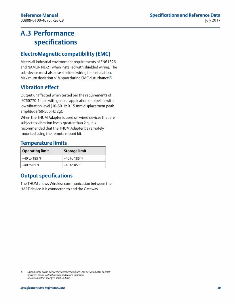
A.3 Performance specifications
ElectroMagnetic compatibility (EMC)Meets all industrial environment requirements of EN61326 and NAMUR NE-21 when installed with shielded wiring. The sub-device must also use shielded wiring for installation. Maximum deviation <1% span during EMC disturbance(1).
Vibration effectOutput unaffected when tested per the requirements of IEC60770-1 field with general application or pipeline with low vibration level (10-60 Hz 0.15 mm displacement peak amplitude/60-500 Hz 2g).
When the THUM Adapter is used on wired devices that are subject to vibration levels greater than 2 g, it is recommended that the THUM Adapter be remotely mounted using the remote mount kit.
Temperature limits
Output specificationsThe THUM allows Wireless communication between the HART device it is connected to and the Gateway.
1. During surge event, device may exceed maximum EMC deviation limit or reset; however, device will self recover and return to normal operation within specified start-up time.
Operating limit Storage limit
–40 to 185 °F –40 to 185 °F
–40 to 85 °C –40 to 85 °C
Specifications and Reference Data 40
Specifications and Reference DataJuly 2017
Reference Manual00809-0100-4075, Rev CB
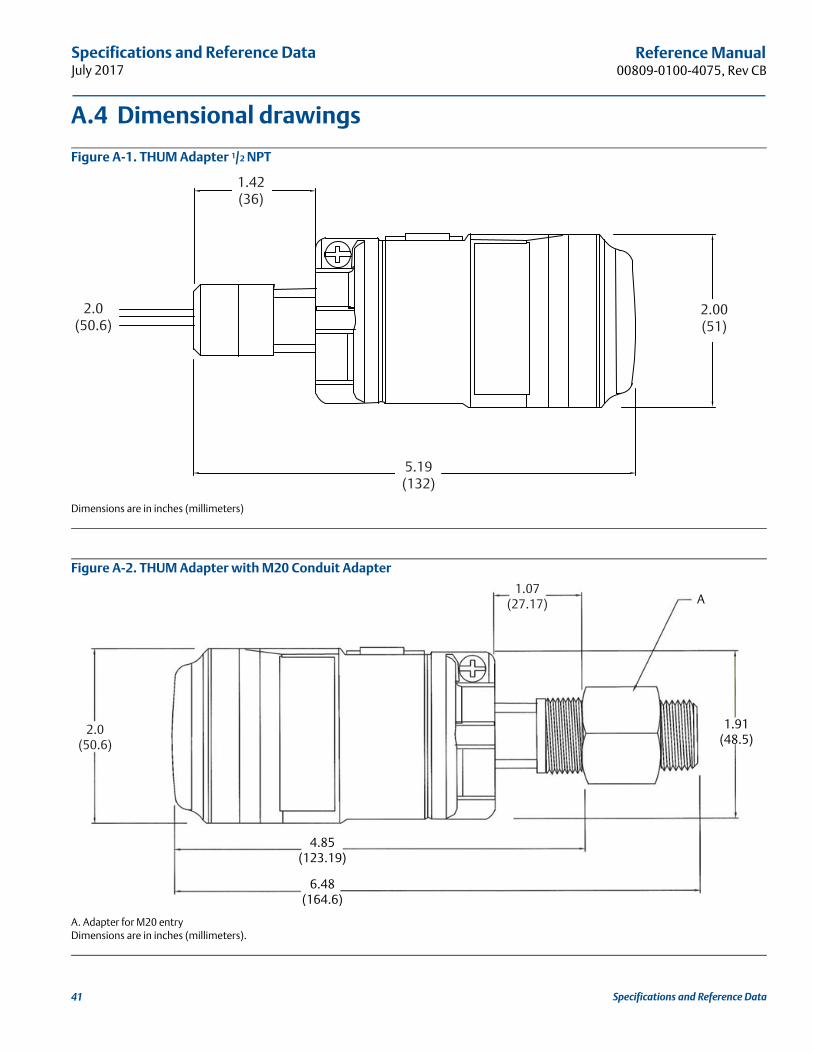
A.4 Dimensional drawings
Figure A-1. THUM Adapter 1/2 NPT
Dimensions are in inches (millimeters)
Figure A-2. THUM Adapter with M20 Conduit Adapter
A. Adapter for M20 entryDimensions are in inches (millimeters).
1.42(36)
2.00(51)
5.19(132)
2.0(50.6)
2.0(50.6)
1.07(27.17) A
1.91(48.5)
4.85(123.19)
6.48(164.6)
Specifications and Reference Data41
Specifications and Reference DataJuly 2017
Reference Manual 00809-0100-4075, Rev CB
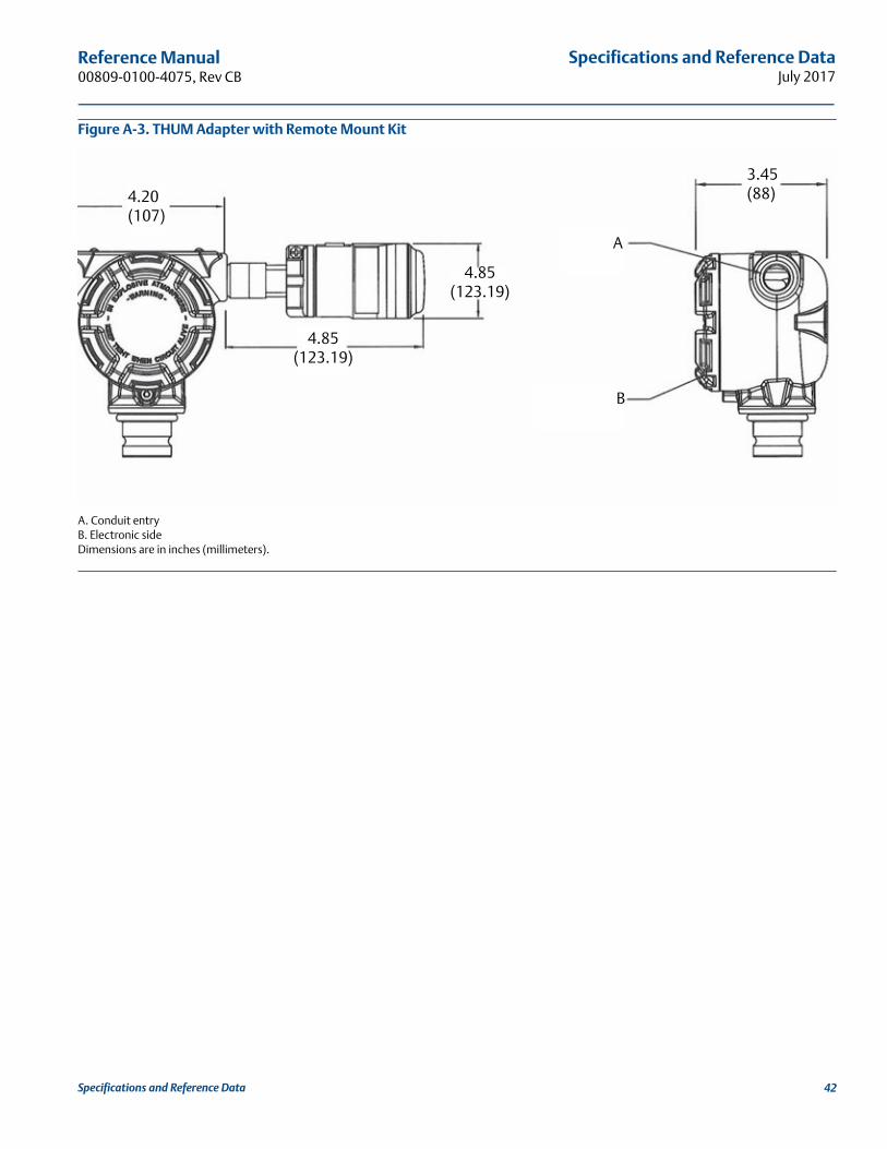
Figure A-3. THUM Adapter with Remote Mount Kit
A. Conduit entryB. Electronic sideDimensions are in inches (millimeters).
4.20(107)
4.85(123.19)
4.85(123.19)
A
B
3.45(88)
Specifications and Reference Data 42
Specifications and Reference DataJuly 2017
Reference Manual00809-0100-4075, Rev CB
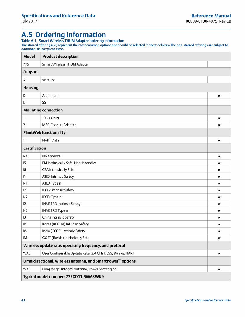
A.5 Ordering informationTable A-1. Smart Wireless THUM Adapter ordering informationThe starred offerings (★) represent the most common options and should be selected for best delivery. The non-starred offerings are subject to additional delivery lead time.
Model Product description
775 Smart Wireless THUM Adapter
Output
X Wireless
Housing
D Aluminum ★
E SST
Mounting connection
1 1/2 - 14 NPT ★
2 M20-Conduit Adapter ★
PlantWeb functionality
1 HART Data ★
Certification
NA No Approval ★
I5 FM Intrinsically Safe, Non-incendive ★
I6 CSA Intrinsically Safe ★
I1 ATEX Intrinsic Safety ★
N1 ATEX Type n ★
I7 IECEx Intrinsic Safety ★
N7 IECEx Type n ★
I2 INMETRO Intrinsic Safety ★
N2 INMETRO Type n ★
I3 China Intrinsic Safety ★
IP Korea (KOSHA) Intrinsic Safety ★
IW India (CCOE) Intrinsic Safety ★
IM GOST (Russia) Intrinsically Safe ★
Wireless update rate, operating frequency, and protocol
WA3 User Configurable Update Rate, 2.4 GHz DSSS, WirelessHART ★
Omnidirectional, wireless antenna, and SmartPower™ options
WK9 Long range, Integral Antenna, Power Scavenging ★
Typical model number: 775XD11I5WA3WK9
Specifications and Reference Data43
Specifications and Reference DataJuly 2017
Reference Manual 00809-0100-4075, Rev CB
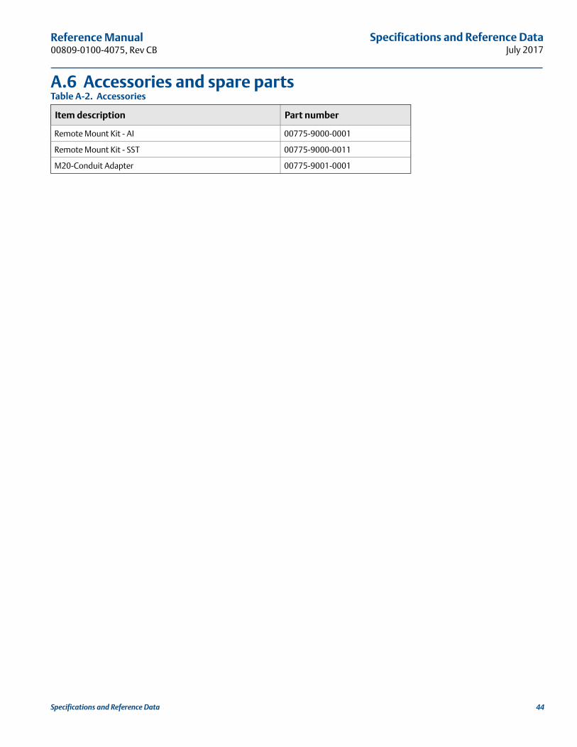
A.6 Accessories and spare partsTable A-2. Accessories
Item description Part number
Remote Mount Kit - AI 00775-9000-0001
Remote Mount Kit - SST 00775-9000-0011
M20-Conduit Adapter 00775-9001-0001
Specifications and Reference Data 44

Product CertificationsJuly 2017
Reference Manual00809-0200-4420, Rev HD
Appendix B Product CertificationsRev 2.2
European Directive Information . . . . . . . . . . . . . . . . . . . . . . . . . . . . . . . . . . . . . . . . . . . . . . . . . . . . . . . . page 45Ordinary Location Certification from FM Approvals . . . . . . . . . . . . . . . . . . . . . . . . . . . . . . . . . . . . . . . page 45Telecommunication compliance (for wireless products only) . . . . . . . . . . . . . . . . . . . . . . . . . . . . . . . page 45FCC and IC (for wireless products only) . . . . . . . . . . . . . . . . . . . . . . . . . . . . . . . . . . . . . . . . . . . . . . . . . . page 45Installing Equipment in North America . . . . . . . . . . . . . . . . . . . . . . . . . . . . . . . . . . . . . . . . . . . . . . . . . . page 45
B.1 European Directive Information
A copy of the EC Declaration of Conformity can be found at the end of the Quick Start Guide. The most recent revision of the EC Declaration of Conformity can be found at Emerson.com/Rosemount.
B.2 Ordinary Location Certification from FM Approvals
As standard, the transmitter has been examined and tested to determine that the design meets the basic electrical, mechanical, and fire protection requirements by FM Approvals, a nationally recognized test laboratory (NRTL) as accredited by the Federal Occupational Safety and Health Administration (OSHA).
B.3 Telecommunication compliance (for wireless products only)
All wireless devices require certification to ensure that they adhere to regulations regarding the use of the RF spectrum. Nearly every country requires this type of product certification. Emerson is working with governmental agencies around the world to supply fully compliant products and remove the risk of violating country directives or laws governing wireless device usage.
B.4 FCC and IC (for wireless products only)
This device complies with Part 15 of the FCC Rules. Operation is subject to the following conditions: This device may not cause harmful interference. This device must accept any interference received, including interference that may cause undesired operation. This device must be installed to ensure a minimum antenna separation distance of 20 cm from all persons.
B.5 Installing Equipment in North America
The US National Electrical Code (NEC) and the Canadian Electrical Code (CEC) permit the use of Division marked equipment in Zones and Zone marked equipment in Divisions. The markings must be suitable for the area classification, gas, and temperature class. This information is clearly defined in the respective codes.
B.6 USAE5 USA Explosionproof
Certificate: CSA 2174201Standards: FM Class 3600 - 2011, FM Class 3615 -
2006, ANSI/UL 61010-1 3rd EditionMarkings: Class I, Division 1, Groups A, B, C and D;
T5, T6; Type 4X and IP66 (–50°C ≤ Ta ≤ +70°C)
Product Certifications45
Product CertificationsJuly 2017
Reference Manual 00809-0200-4420, Rev HD
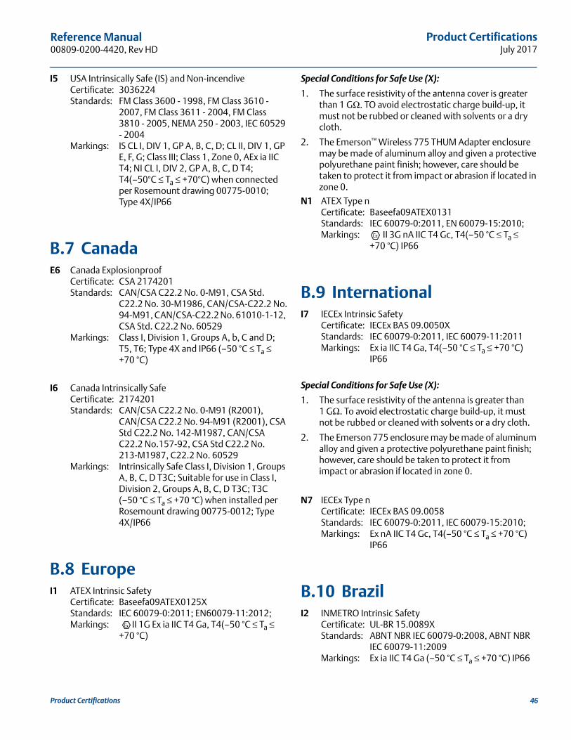
I5 USA Intrinsically Safe (IS) and Non-incendiveCertificate: 3036224Standards: FM Class 3600 - 1998, FM Class 3610 -
2007, FM Class 3611 - 2004, FM Class 3810 - 2005, NEMA 250 - 2003, IEC 60529 - 2004
Markings: IS CL I, DIV 1, GP A, B, C, D; CL II, DIV 1, GP E, F, G; Class III; Class 1, Zone 0, AEx ia IIC T4; NI CL I, DIV 2, GP A, B, C, D T4; T4(–50°C ≤ Ta ≤ +70°C) when connected per Rosemount drawing 00775-0010; Type 4X/IP66
B.7 CanadaE6 Canada Explosionproof
Certificate: CSA 2174201Standards: CAN/CSA C22.2 No. 0-M91, CSA Std.
C22.2 No. 30-M1986, CAN/CSA-C22.2 No. 94-M91, CAN/CSA-C22.2 No. 61010-1-12, CSA Std. C22.2 No. 60529
Markings: Class I, Division 1, Groups A, b, C and D; T5, T6; Type 4X and IP66 (–50 °C ≤ Ta ≤ +70 °C)
I6 Canada Intrinsically SafeCertificate: 2174201Standards: CAN/CSA C22.2 No. 0-M91 (R2001),
CAN/CSA C22.2 No. 94-M91 (R2001), CSA Std C22.2 No. 142-M1987, CAN/CSA C22.2 No.157-92, CSA Std C22.2 No. 213-M1987, C22.2 No. 60529
Markings: Intrinsically Safe Class I, Division 1, Groups A, B, C, D T3C; Suitable for use in Class I, Division 2, Groups A, B, C, D T3C; T3C(–50 °C ≤ Ta ≤ +70 °C) when installed per Rosemount drawing 00775-0012; Type 4X/IP66
B.8 EuropeI1 ATEX Intrinsic Safety
Certificate: Baseefa09ATEX0125XStandards: IEC 60079-0:2011; EN60079-11:2012;Markings: II 1G Ex ia IIC T4 Ga, T4(–50 °C ≤ Ta ≤
+70 °C)
Special Conditions for Safe Use (X):
1. The surface resistivity of the antenna cover is greater than 1 GΩ. TO avoid electrostatic charge build-up, it must not be rubbed or cleaned with solvents or a dry cloth.
2. The Emerson™ Wireless 775 THUM Adapter enclosure may be made of aluminum alloy and given a protective polyurethane paint finish; however, care should be taken to protect it from impact or abrasion if located in zone 0.
N1 ATEX Type nCertificate: Baseefa09ATEX0131Standards: IEC 60079-0:2011, EN 60079-15:2010;Markings: II 3G nA IIC T4 Gc, T4(–50 °C ≤ Ta ≤
+70 °C) IP66
B.9 InternationalI7 IECEx Intrinsic Safety
Certificate: IECEx BAS 09.0050XStandards: IEC 60079-0:2011, IEC 60079-11:2011Markings: Ex ia IIC T4 Ga, T4(–50 °C ≤ Ta ≤ +70 °C)
IP66
Special Conditions for Safe Use (X):
1. The surface resistivity of the antenna is greater than 1 GΩ. To avoid electrostatic charge build-up, it must not be rubbed or cleaned with solvents or a dry cloth.
2. The Emerson 775 enclosure may be made of aluminum alloy and given a protective polyurethane paint finish; however, care should be taken to protect it from impact or abrasion if located in zone 0.
N7 IECEx Type nCertificate: IECEx BAS 09.0058Standards: IEC 60079-0:2011, IEC 60079-15:2010;Markings: Ex nA IIC T4 Gc, T4(–50 °C ≤ Ta ≤ +70 °C)
IP66
B.10 BrazilI2 INMETRO Intrinsic Safety
Certificate: UL-BR 15.0089XStandards: ABNT NBR IEC 60079-0:2008, ABNT NBR
IEC 60079-11:2009Markings: Ex ia IIC T4 Ga (–50 °C ≤ Ta ≤ +70 °C) IP66
Product Certifications 46

Product CertificationsJuly 2017
Reference Manual00809-0200-4420, Rev HD
Special Conditions for Safe Use (X):
1. The surface resistivity of the antenna is greater than 1 GΩ. To avoid electrostatic charge build-up, it must not be rubbed or cleaned with solvents or a dry cloth.
2. The enclosure may be made of aluminum alloy and given a protective polyurethane paint finish; special care must be taken to minimize the risk of impact or friction of the housing which can cause the generation of sparks.
N2 INMETRO Type nCertificate: UL-BR 15.0027Standards: ABNT NBR IEC 60079-0:2008, IEC
60079-15:2010;Markings: Ex nA IIC T4 Gc (–50 °C ≤ Ta ≤ +70 °C) IP66
B.11 ChinaI3 NEPSI Intrinsic Safety
Certificate: GYJ14.1094XStandards: GB3836.1 - 2010, GB3836.4 - 2010,
GB3836.20-2010Markings: Ex ia IIC T4 Ga, –50 ~ +70 °C
Special Condition for Safe Use (X):
1. See certificate for special conditions.
B.12 JapanI4 TIIS Intrinsic Safety
Certificate: TC22150XMarkings: Ex ia IIB T4 Ga, –50 °C ~ +70 °C
Special Condition for Safe Use (X):
1. See certificate for special conditions.
B.13 EAC - Belarus, Kazakhstan, Russia
IM Technical Regulation Customs Union (EAC) Intrinsic SafetyCertificate: TC RU C-US.AA87.B.00228Markings: 0Ex ia IIC T4 Ga X T4 (-50°C ≤ Ta ≤ +70 °C)
IP66
Special Condition for Safe Use (X):
1. See certificate for special conditions.
NM Technical Regulation Customs Union (EAC) Type nCertificate: TC RU C-US.AA87.B.00228Markings: 2Ex nA IIC T4 Gc X T4 (–50 °C ≤ Ta ≤ +70 °C)
IP66
Special Condition for Safe Use (X):
1. See certificate for special conditions.
B.14 Republic of KoreaIP Korea (KOSHA) Intrinsic Safety
Certificate: 10-KB4BO-0010XMarkings: Ex ia IIC T4
Special Conditions for Safe Use (X):
1. See certificate for special conditions.
B.15 IndiaIW India (CCOE) Intrinsic Safety
Certificate: A/P/HQ/MH/104/2023(P242867)Markings: Ex ia IIC T4
B.16 CombinationsKM Combination of IM and NM
Product Certifications47
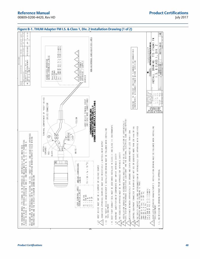
Product CertificationsJuly 2017
Reference Manual 00809-0200-4420, Rev HD
Figure B-1. THUM Adapter FM I.S. & Class 1, Div. 2 Installation Drawing (1 of 2)
Product Certifications 48
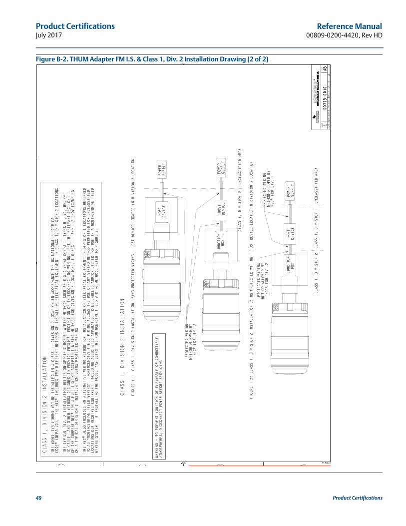
Product CertificationsJuly 2017
Reference Manual00809-0200-4420, Rev HD
Figure B-2. THUM Adapter FM I.S. & Class 1, Div. 2 Installation Drawing (2 of 2)
Product Certifications49
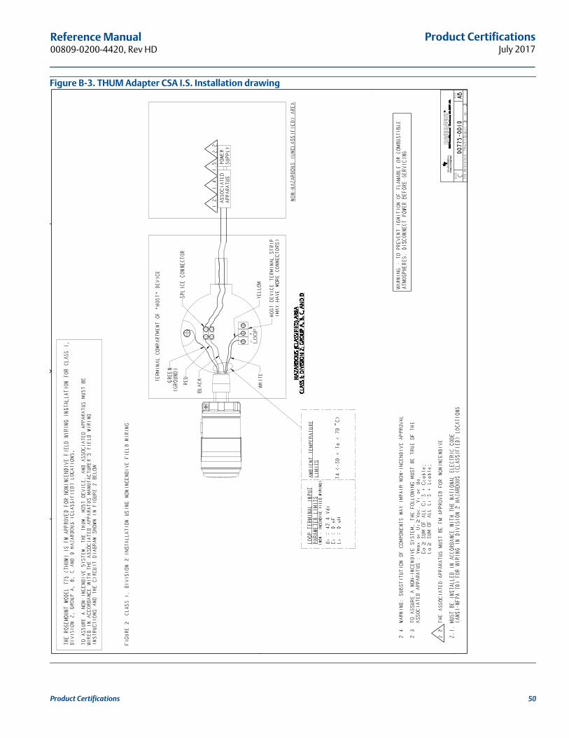
Product CertificationsJuly 2017
Reference Manual 00809-0200-4420, Rev HD
Figure B-3. THUM Adapter CSA I.S. Installation drawing
Product Certifications 50
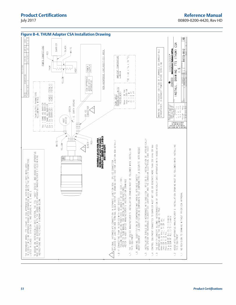
Product CertificationsJuly 2017
Reference Manual00809-0200-4420, Rev HD
Figure B-4. THUM Adapter CSA Installation Drawing
Product Certifications51

Product CertificationsJuly 2017
Reference Manual 00809-0200-4420, Rev HD
Product Certifications 52


Reference Manual00809-0100-4075, Rev CB
July 2017
Global Headquarters
Emerson Automation Solutions 6021 Innovation Blvd.Shakopee, MN 55379, USA+1 800 999 9307 or +1 952 906 8888+1 952 949 7001 [email protected]
North America Regional OfficeEmerson Automation Solutions8200 Market Blvd.Chanhassen, MN 55317, USA
+1 800 999 9307 or +1 952 906 8888+1 952 949 7001 [email protected]
Latin America Regional OfficeEmerson Automation Solutions1300 Concord Terrace, Suite 400Sunrise, FL 33323, USA
+1 954 846 5030+1 954 846 [email protected]
Europe Regional OfficeEmerson Automation Solutions Europe GmbHNeuhofstrasse 19a P.O. Box 1046CH 6340 BaarSwitzerland
+41 (0) 41 768 6111+41 (0) 41 768 6300 [email protected]
Asia Pacific Regional OfficeEmerson Automation Solutions Asia Pacific Pte Ltd
Linkedin.com/company/Emerson-Automation-Solutions
Twitter.com/Rosemount_News
1 Pandan CrescentSingapore 128461
+65 6777 8211+65 6777 0947 [email protected]
Middle East and Africa Regional OfficeEmerson Automation SolutionsEmerson FZE P.O. Box 17033Jebel Ali Free Zone - South 2Dubai, United Arab Emirates
+971 4 8118100+971 4 8865465 [email protected]
Facebook.com/Rosemount
Youtube.com/user/RosemountMeasurement
Google.com/+RosemountMeasurement
Standard Terms and Conditions of Sale can be found on the Terms and Conditions of Sale page.The Emerson logo is a trademark and service mark of Emerson Electric Co.THUM Adapter,Plantweb, SmartPower, Rosemount, and the Rosemount logotype are trademarks of Emerson.HART and WirelessHART are registered trademark of the FieldComm Group.All other marks are the property of their respective owners.© 2017 Emerson. All rights reserved.