Embed Size (px)
Citation preview
Assurance Activity Report
Emerson Network Power Secure KVM and Matrix
Peripheral Switch Protection Profile
Document version: 1.0
February 2016
Document prepared by
Emerson Network Power Secure KVM Switch
Assurance Activity Report v1.0 Page ii
Document History
Version Date Author Description
1.0 February 26, 2016 B Pleffner Final Report
Emerson Network Power Secure KVM Switch
Assurance Activity Report v1.0 Page iii
Intentionally left blank
Emerson Network Power Secure KVM Switch
Assurance Activity Report v1.0 Page 4
Table of Contents
1 INTRODUCTION ..................................................................................................... 6
1.1 OVERVIEW ........................................................................................................... 6
2 TOE EVALUATION SPECIFICS .......................................................................... 7
2.1 DOCUMENT REFERENCES ..................................................................................... 7
2.2 EVALUATED PLATFORMS (FROM SECURITY TARGET) .......................................... 7
2.3 EQUIVALENCY ..................................................................................................... 9
3 EVALUATION ....................................................................................................... 11
3.1 TECHNIQUES, TOOLS AND STANDARDS .............................................................. 11
3.2 TEST CONFIGURATION ....................................................................................... 13
3.2.1 Test Setup C (2P HDMI KVM switch) ............................................................. 13
3.2.2 Test Setup D (4P DP KVM switch).................................................................. 13
3.2.3 Test Setup F (4P Mini-Matrix KVM switch) ................................................... 13
3.2.4 Test Setup I (8P KVM switch) ........................................................................ 13
3.3 TEST CONFIGURATION DIAGRAM ....................................................................... 16
4 ASSURANCE ACTIVITIES FOR PSS PP .......................................................... 20
4.1 FDP_IFC.1 (1) SUBSET INFORMATION FLOW CONTROL ..................................... 20
4.2 FDP_IFF.1 (1) SIMPLE SECURITY ATTRIBUTES .................................................. 21
4.3 FDP_IFC.1 (2) SUBSET INFORMATION FLOW CONTROL ..................................... 25
4.4 FDP_IFF.1 (2) SIMPLE SECURITY ATTRIBUTES .................................................. 25
4.5 FDP_ACC.1 SUBSET ACCESS CONTROL ............................................................ 53
4.6 FDP_ACF.1 SECURITY ATTRIBUTE BASED ACCESS CONTROL ............................ 54
4.7 FDP_RIP.1 SUBSET RESIDUAL INFORMATION PROTECTION .............................. 59
4.8 FPT_PHP.1 SUBSET RESIDUAL INFORMATION PROTECTION .............................. 62
4.9 FPT_PHP.3 SUBSET RESIDUAL INFORMATION PROTECTION .............................. 64
4.10 FPT_FLS.1 FAILURE WITH PRESERVATION OF SECURE STATE ........................... 68
4.11 FPT_TST.1 TSF TESTING .................................................................................. 70
4.12 FTA_CIN_EXT.1 EXTENDED: CONTINUOUS INDICATIONS ............................... 74
4.13 FAU_GEN.1: AUDIT DATA GENERATION ......................................................... 76
4.14 FIA_UAU.2 USER AUTHENTICATION BEFORE ANY ACTION ............................... 78
4.15 FIA_UID.2 USER IDENTIFICATION BEFORE ANY ACTION ................................... 79
4.16 FMT_MOF.1 MANAGEMENT OF SECURITY FUNCTIONS BEHAVIOR ................... 79
Emerson Network Power Secure KVM Switch
Assurance Activity Report v1.0 Page 5
4.17 FMT_SMF.1 MANAGEMENT OF SECURITY FUNCTIONS BEHAVIOR .................... 81
4.18 FMT_SMR.1 SECURITY ROLES ......................................................................... 83
4.19 FTA_ATH_EXT.1 USER AUTHENTICATION DEVICE RESET ............................... 84
4.20 ADV_FSP.1 BASIC FUNCTIONAL SPECIFICATION ............................................. 86
4.21 AGD_OPE.1 OPERATIONAL USER GUIDANCE .................................................. 87
4.22 AGD_PRE.1 PREPARATIVE PROCEDURES ......................................................... 87
4.23 ATE_IND.1 INDEPENDENT TESTING - CONFORMANCE ..................................... 89
4.24 ALC_CMC.1 LABELING OF THE TOE ............................................................... 91
4.25 ALC_CMS.1 TOE CM COVERAGE ................................................................... 94
5 CONCLUSIONS AND RECOMMENDATIONS ................................................ 95
6 LIST OF EVALUATION EVIDENCE ................................................................. 96
7 PRODUCT COMPLIANCE LISTING ENTRY ................................................. 97
8 LIST OF ACRONYMS/GLOSSARY OF TERMS ............................................. 98
9 ANNEX A - RATIONALE FOR TEST COVERAGE OF MULTIPLE TOE
MODELS ......................................................................................................................... 99
9.1 JUSTIFICATION FOR SELECTION MADE BY EMERSON ........................................ 101
9.1.1 Secure 2P KVM Switch (Group C) ................................................................ 101
9.1.2 Secure 4P KVM Switch (Group D) ................................................................ 103
9.1.3 Secure Mini-matrix (Group F) ...................................................................... 104
9.1.4 Secure 8/16P KVM Switch (Group I) ............................................................ 105
9.2 SUMMERY ........................................................................................................ 106
9.2.1 Number of ports / enclosures ...................................................................... 106
9.2.2 Operation Mode .......................................................................................... 106
9.2.3 Video Protocols Supported .......................................................................... 106
9.2.4 DPP function Supported .............................................................................. 106
Emerson Network Power Secure KVM Switch
Assurance Activity Report v1.0 Page 6
1 Introduction
1.1 Overview
This Assurance Activity Report (AAR) documents the evaluation of Emerson KVM
Switches.
Emerson Network Power is the sponsor of this evaluation which is being conducted by
CSC Security Testing and Certification Laboratory (STCL) under the United States
National Information Assurance Partnership (NIAP) Common Criteria Evaluation and
Validation Scheme (CCEVS).
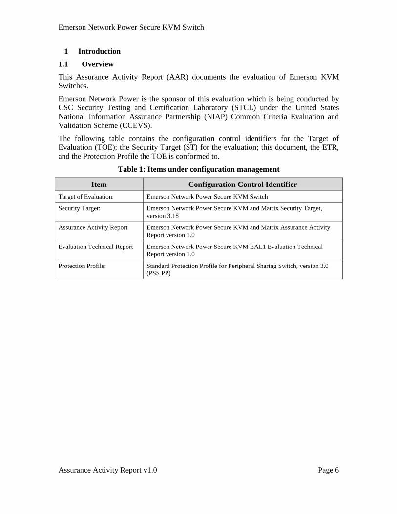
The following table contains the configuration control identifiers for the Target of
Evaluation (TOE); the Security Target (ST) for the evaluation; this document, the ETR,
and the Protection Profile the TOE is conformed to.
Table 1: Items under configuration management
Item Configuration Control Identifier
Target of Evaluation: Emerson Network Power Secure KVM Switch
Security Target: Emerson Network Power Secure KVM and Matrix Security Target,
version 3.18
Assurance Activity Report Emerson Network Power Secure KVM and Matrix Assurance Activity
Report version 1.0
Evaluation Technical Report Emerson Network Power Secure KVM EAL1 Evaluation Technical
Report version 1.0
Protection Profile: Standard Protection Profile for Peripheral Sharing Switch, version 3.0
(PSS PP)
Emerson Network Power Secure KVM Switch
Assurance Activity Report v1.0 Page 7
2 TOE Evaluation Specifics
2.1 Document References
Table 2: Referenced documents
Ref. Document
[A] Emerson Secure KVM and Matrix Assurance Activity Report (this document)
[B] Emerson Secure KVM and Matrix Security Target, version 3.18
[C] EMERSON 2-PORT DH KVM User Manual PP3
[D] EMERSON 2-PORT SH KVM User Manual PP3
[E] EMERSON 4-PORT DH KVM User Manual PP3
[F] EMERSON 4-PORT SH KVM User Manual PP3
[G] EMERSON 2-Port Mini-Matrix User Manual PP3
[H] EMERSON 4-Port Mini-Matrix User Manual PP3
[I] EMERSON MIXED DUAL 2-PORT KVM User Manual PP3
[J] EMERSON MIXED DUAL 4-PORT KVM User Manual PP3
[K] EMERSON 8/16-Port Secure KVM User Manual PP3
[L] EMERSON MIXED TRIPLE 4-PORT KVM User Manual PP3
[M] Emerson Administrator Guide
[N] Emerson DPP Configuration Manual
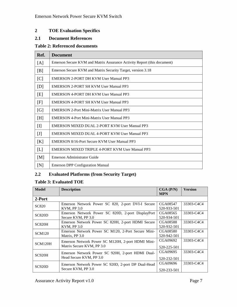
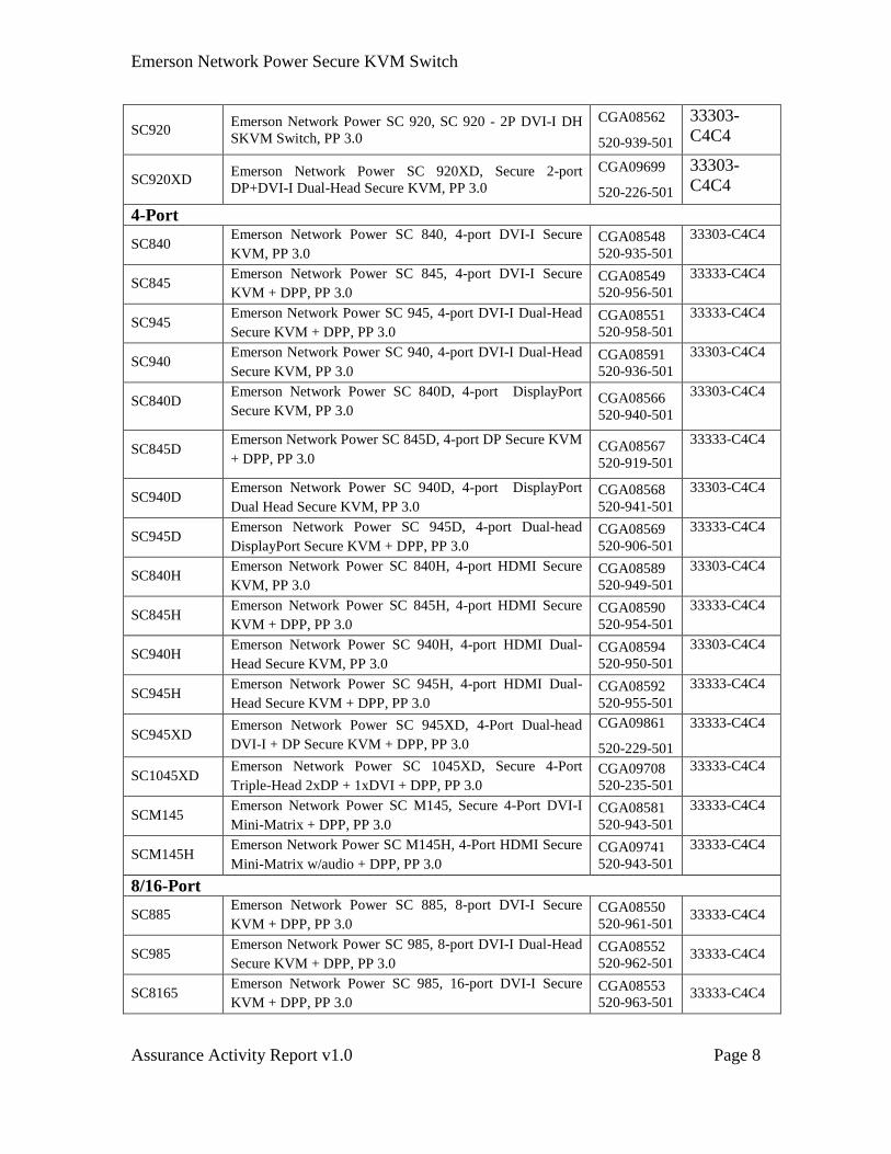
2.2 Evaluated Platforms (from Security Target)
Table 3: Evaluated TOE
Model Description CGA (P/N)
MPN
Version
2-Port
SC820 Emerson Network Power SC 820, 2-port DVI-I Secure
KVM, PP 3.0
CGA08547
520-933-501
33303-C4C4
SC820D Emerson Network Power SC 820D, 2-port DisplayPort
Secure KVM, PP 3.0
CGA08565
520-934-501
33303-C4C4
SC820H Emerson Network Power SC 820H, 2-port HDMI Secure
KVM, PP 3.0
CGA08588
520-932-501
33303-C4C4
SCM120 Emerson Network Power SC M120, 2-Port Secure Mini-
Matrix, PP 3.0
CGA08580
520-942-501
33303-C4C4
SCM120H Emerson Network Power SC M120H, 2-port HDMI Mini-
Matrix Secure KVM, PP 3.0
CGA09692
520-225-501
33303-C4C4
SC920H Emerson Network Power SC 920H, 2-port HDMI Dual-
Head Secure KVM, PP 3.0
CGA09695
520-232-501
33303-C4C4
SC920D Emerson Network Power SC 920D, 2-port DP Dual-Head
Secure KVM, PP 3.0
CGA09696
520-233-501
33303-C4C4
Emerson Network Power Secure KVM Switch
Assurance Activity Report v1.0 Page 8
SC920 Emerson Network Power SC 920, SC 920 - 2P DVI-I DH
SKVM Switch, PP 3.0
CGA08562
520-939-501
33303-
C4C4
SC920XD Emerson Network Power SC 920XD, Secure 2-port
DP+DVI-I Dual-Head Secure KVM, PP 3.0
CGA09699
520-226-501
33303-
C4C4
4-Port
SC840 Emerson Network Power SC 840, 4-port DVI-I Secure
KVM, PP 3.0
CGA08548
520-935-501
33303-C4C4
SC845 Emerson Network Power SC 845, 4-port DVI-I Secure
KVM + DPP, PP 3.0
CGA08549
520-956-501
33333-C4C4
SC945 Emerson Network Power SC 945, 4-port DVI-I Dual-Head
Secure KVM + DPP, PP 3.0
CGA08551
520-958-501
33333-C4C4
SC940 Emerson Network Power SC 940, 4-port DVI-I Dual-Head
Secure KVM, PP 3.0
CGA08591
520-936-501
33303-C4C4
SC840D Emerson Network Power SC 840D, 4-port DisplayPort
Secure KVM, PP 3.0 CGA08566
520-940-501
33303-C4C4
SC845D Emerson Network Power SC 845D, 4-port DP Secure KVM
+ DPP, PP 3.0 CGA08567
520-919-501
33333-C4C4
SC940D Emerson Network Power SC 940D, 4-port DisplayPort
Dual Head Secure KVM, PP 3.0
CGA08568
520-941-501
33303-C4C4
SC945D Emerson Network Power SC 945D, 4-port Dual-head
DisplayPort Secure KVM + DPP, PP 3.0
CGA08569
520-906-501
33333-C4C4
SC840H Emerson Network Power SC 840H, 4-port HDMI Secure
KVM, PP 3.0
CGA08589
520-949-501
33303-C4C4
SC845H Emerson Network Power SC 845H, 4-port HDMI Secure
KVM + DPP, PP 3.0
CGA08590
520-954-501
33333-C4C4
SC940H Emerson Network Power SC 940H, 4-port HDMI Dual-
Head Secure KVM, PP 3.0
CGA08594
520-950-501
33303-C4C4
SC945H Emerson Network Power SC 945H, 4-port HDMI Dual-
Head Secure KVM + DPP, PP 3.0
CGA08592
520-955-501
33333-C4C4
SC945XD Emerson Network Power SC 945XD, 4-Port Dual-head
DVI-I + DP Secure KVM + DPP, PP 3.0
CGA09861
520-229-501
33333-C4C4
SC1045XD Emerson Network Power SC 1045XD, Secure 4-Port
Triple-Head 2xDP + 1xDVI + DPP, PP 3.0
CGA09708
520-235-501
33333-C4C4
SCM145 Emerson Network Power SC M145, Secure 4-Port DVI-I
Mini-Matrix + DPP, PP 3.0
CGA08581
520-943-501
33333-C4C4
SCM145H Emerson Network Power SC M145H, 4-Port HDMI Secure
Mini-Matrix w/audio + DPP, PP 3.0
CGA09741
520-943-501
33333-C4C4
8/16-Port
SC885 Emerson Network Power SC 885, 8-port DVI-I Secure
KVM + DPP, PP 3.0
CGA08550
520-961-501 33333-C4C4
SC985 Emerson Network Power SC 985, 8-port DVI-I Dual-Head
Secure KVM + DPP, PP 3.0
CGA08552
520-962-501 33333-C4C4
SC8165 Emerson Network Power SC 985, 16-port DVI-I Secure
KVM + DPP, PP 3.0
CGA08553
520-963-501 33333-C4C4
Emerson Network Power Secure KVM Switch
Assurance Activity Report v1.0 Page 9
2.3 Equivalency
The Design Documentation describes a low-level breakdown of the TOE including
firmware logic and circuitry. Review of this document shows how the circuitry is
extended to include more ports for the 2, 4, 8 and 16 port models.
Because the number of ports on the KVM switch has no effect on the security threats
associated with it, it is adequate to test a specific function on one product with arbitrary
number of channels. For example in table 3 above, it is enough to test the SC945D 4-Port
DisplayPort video KVM to show compliancy with the PP in 2, and 4 port models. It
should be noted that both video functions and peripheral functions are identical in
hardware and firmware across the different models.
DisplayPort requires special testing based on the referenced PP and therefore the 4-Port
SC945D selected as a representative model for this group of products. It should be noted
here that the same video board used in the SC945D is used in all other DP video
products.
This document describes the testing procedure for the 28 TOE shown in table 3 above.
The scope of the test plans includes only the claimed SFR’s, which are identical for each
model of the KVM switch. Each test case verifies one or more SFR’s in the Security
Target. The only model specific test cases are those that iterate through each computer in
order to verify that each port is working as intended. The test cases can be applied to any
model of the KVM by changing the number of computers tested.
Based on the design presented in the ST, and the test cases defined in this document,
there are no aspects of the different models that are not covered in testing a single model.
The primary differences between the various evaluated products are:
1) Hardware differences:
a) The number of ports that the KVM support – 2, 4, 8 or 16;
b) Single versus dual-head models. Dual-head models are identical to
single-head models but having extra instances of video boards;
c) Models with and without DPP function; and
d) All TOE are sharing the same firmware and significant similarities
in the hardware designs. The development and production
processes of the different models are identical.
2) The rationale provided in the Annex B of this document.
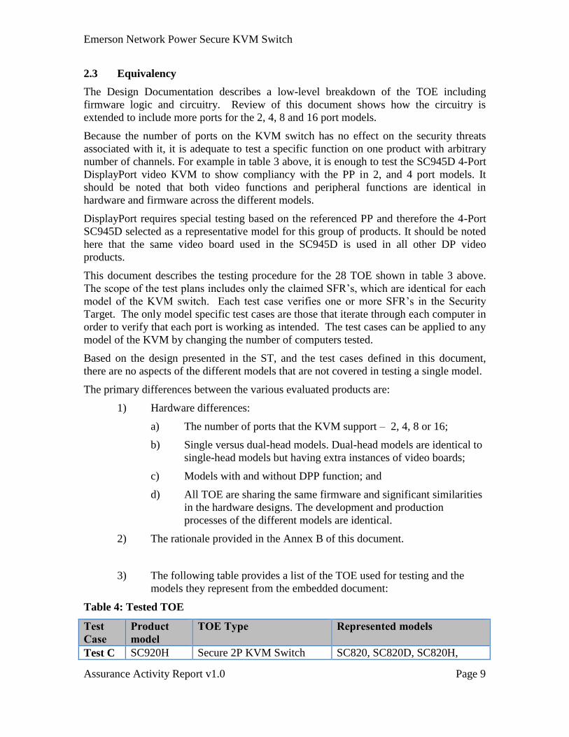
3) The following table provides a list of the TOE used for testing and the
models they represent from the embedded document:
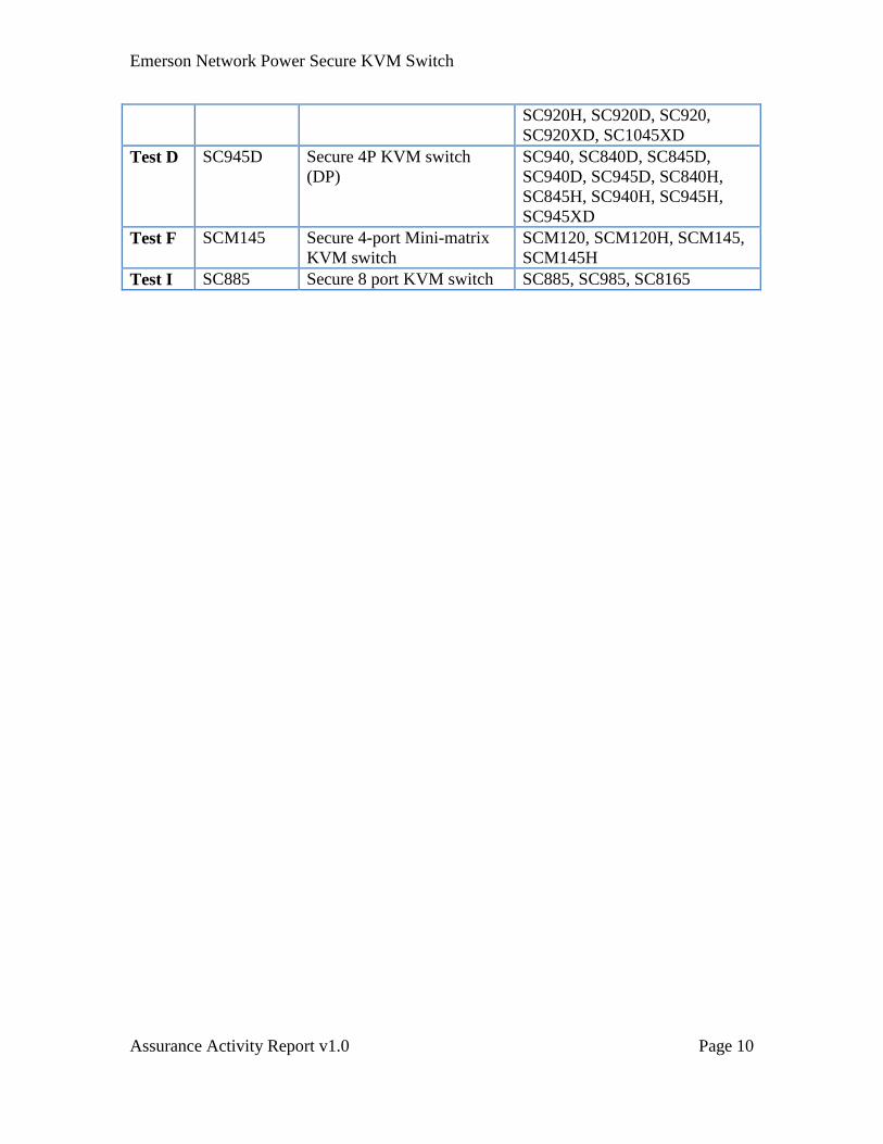
Table 4: Tested TOE
Test
Case
Product
model
TOE Type Represented models
Test C SC920H Secure 2P KVM Switch SC820, SC820D, SC820H,
Emerson Network Power Secure KVM Switch
Assurance Activity Report v1.0 Page 10
SC920H, SC920D, SC920,
SC920XD, SC1045XD
Test D SC945D Secure 4P KVM switch
(DP)
SC940, SC840D, SC845D,
SC940D, SC945D, SC840H,
SC845H, SC940H, SC945H,
SC945XD
Test F SCM145 Secure 4-port Mini-matrix
KVM switch
SCM120, SCM120H, SCM145,
SCM145H
Test I SC885 Secure 8 port KVM switch SC885, SC985, SC8165
Emerson Network Power Secure KVM Switch
Assurance Activity Report v1.0 Page 11
3 Evaluation
Emerson KVM Switches is the Target of Evaluation (TOE) under the Standard Protection
Profile for Peripheral Sharing Switches, version 3.0.
3.1 Techniques, Tools and Standards
The standards used in the conduct of this evaluation:
Common Criteria for Information Technology Security Evaluation Part 1:
Introduction and general model September 2012 Version 3.1 Revision 4
Common Criteria for Information Technology Security Evaluation Part 2:
Security functional components September 2012 Version 3.1 Revision 4
Common Criteria for Information Technology Security Evaluation Part 3:
Security assurance components September 2012 Version 3.1 Revision 4
Common Methodology for Information Technology Security Evaluation
methodology September 2012 Version 3.1 Revision 4
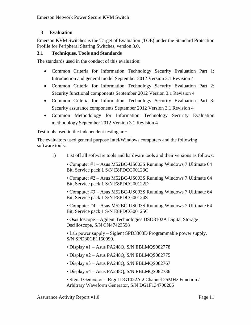
Test tools used in the independent testing are:
The evaluators used general purpose Intel/Windows computers and the following
software tools:
1) List off all software tools and hardware tools and their versions as follows:
• Computer #1 – Asus M52BC-US003S Running Windows 7 Ultimate 64
Bit, Service pack 1 S/N E8PDCG00123C
• Computer #2 – Asus M52BC-US003S Running Windows 7 Ultimate 64
Bit, Service pack 1 S/N E8PDCG00122D
• Computer #3 – Asus M52BC-US003S Running Windows 7 Ultimate 64
Bit, Service pack 1 S/N E8PDCG00124S
• Computer #4 – Asus M52BC-US003S Running Windows 7 Ultimate 64
Bit, Service pack 1 S/N E8PDCG00125C
• Oscilloscope – Agilent Technologies DSO3102A Digital Storage
Oscilloscope, S/N CN47423598
• Lab power supply – Siglent SPD3303D Programmable power supply,
S/N SPD30CE1150090.
• Display #1 – Asus PA248Q, S/N EBLMQS082778
• Display #2 – Asus PA248Q, S/N EBLMQS082775
• Display #3 – Asus PA248Q, S/N EBLMQS082767
• Display #4 – Asus PA248Q, S/N EBLMQS082736
• Signal Generator – Rigol DG1022A 2 Channel 25MHz Function /
Arbitrary Waveform Generator, S/N DG1F134700206
Emerson Network Power Secure KVM Switch
Assurance Activity Report v1.0 Page 12
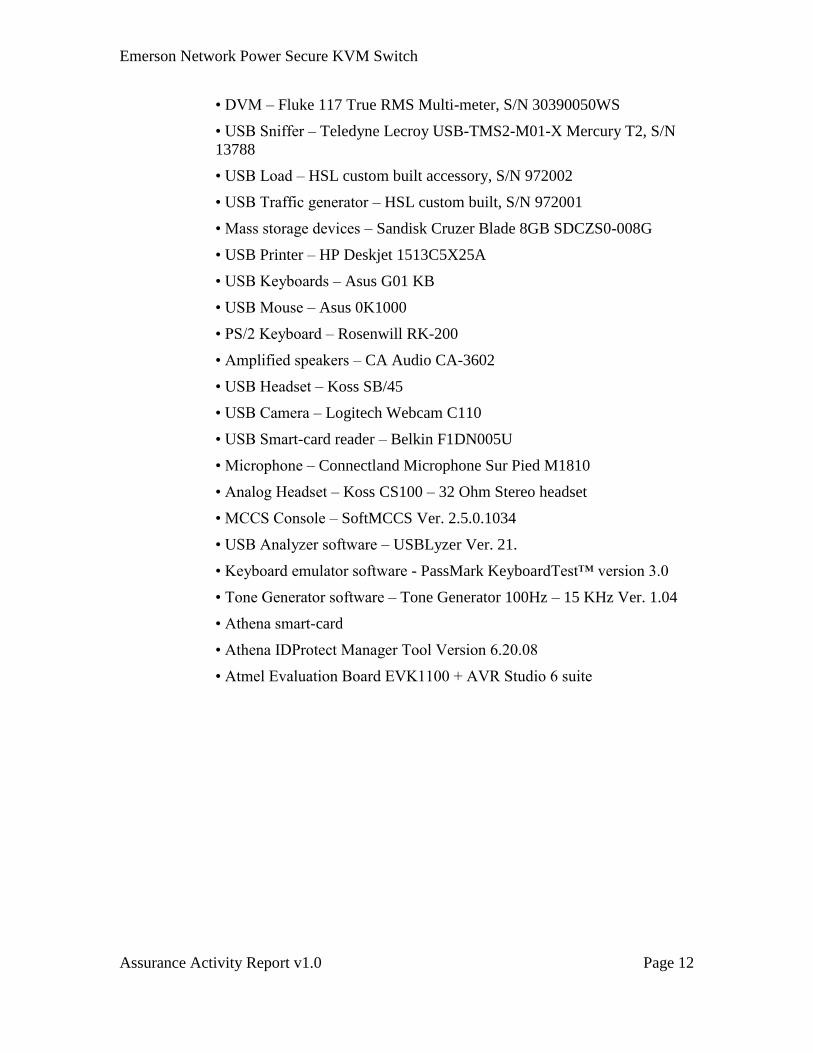
• DVM – Fluke 117 True RMS Multi-meter, S/N 30390050WS
• USB Sniffer – Teledyne Lecroy USB-TMS2-M01-X Mercury T2, S/N
13788
• USB Load – HSL custom built accessory, S/N 972002
• USB Traffic generator – HSL custom built, S/N 972001
• Mass storage devices – Sandisk Cruzer Blade 8GB SDCZS0-008G
• USB Printer – HP Deskjet 1513C5X25A
• USB Keyboards – Asus G01 KB
• USB Mouse – Asus 0K1000
• PS/2 Keyboard – Rosenwill RK-200
• Amplified speakers – CA Audio CA-3602
• USB Headset – Koss SB/45
• USB Camera – Logitech Webcam C110
• USB Smart-card reader – Belkin F1DN005U
• Microphone – Connectland Microphone Sur Pied M1810
• Analog Headset – Koss CS100 – 32 Ohm Stereo headset
• MCCS Console – SoftMCCS Ver. 2.5.0.1034
• USB Analyzer software – USBLyzer Ver. 21.
• Keyboard emulator software - PassMark KeyboardTest™ version 3.0
• Tone Generator software – Tone Generator 100Hz – 15 KHz Ver. 1.04
• Athena smart-card
• Athena IDProtect Manager Tool Version 6.20.08
• Atmel Evaluation Board EVK1100 + AVR Studio 6 suite
Emerson Network Power Secure KVM Switch
Assurance Activity Report v1.0 Page 13
3.2 Test Configuration
3.2.1 Test Setup C (2P HDMI KVM switch)
1 x Emerson SC920H Secure 2-Port KVM (P/N: CGA09695);
1 x Wall mounted power supply (P/N: CPS05296);
2 x HDMI and USB KVM Cable (P/N: CPN05491);
1 x USB Mouse;
1 x USB Keyboard;
2 x PC’s installed with Microsoft Windows 7, Windows 8 or Linux;
2 x HDMI Displays;
1 x Analog audio headset; and
Additional test equipment per table 5 below.
3.2.2 Test Setup D (4P DP KVM switch)
1 x Emerson SC945D Secure 4-Port DP KVM (P/N: CGA08569);
1 x AC Power cable;
4 x DP and USB KVM Cable (P/N: CPN05494);
4 x DPP USB Cable (P/N: CPN05487);
1 x USB Mouse;
1 x USB Keyboard;
1 x Qualified USB smart-card reader;
2 x PC’s installed with Microsoft Windows 7, Windows 8 or Linux;
2 x DP Displays;
1 x Analog audio headset; and
Additional test equipment per table 5 below.
3.2.3 Test Setup F (4P Mini-Matrix KVM switch)
1 x Emerson SCM145 Secure 4-Port Mini-Matrix KVM (P/N: CGA08581);
1 x AC Power cable;
4 x DVI and USB KVM Cable (P/N: CPN05485);
4 x DPP USB Cable (P/N: CPN05487);
1 x USB Mouse;
1 x USB Keyboard;
1 x Qualified USB smart-card reader;
4 x PC’s installed with Microsoft Windows 7, Windows 8 or Linux;
2 x Displays;
1 x Analog audio headset; and
Additional test equipment per table 5 below.
3.2.4 Test Setup I (8P KVM switch)
1 x Emerson SC885 Secure 8-Port KVM (P/N: CGA08550);
1 x AC Power cable;
8 x DVI and USB KVM Cable (P/N: CPN05485);
8 x DPP USB Cable (P/N: CPN05487);
Emerson Network Power Secure KVM Switch
Assurance Activity Report v1.0 Page 14
1 x USB Mouse;
1 x USB Keyboard;
1 x Qualified smart-card;
4 x PC’s installed with Microsoft Windows 7, Windows 8 or Linux;
1 x DVI Displays;
1 x Analog audio headset; and
Additional test equipment per table 5 below.
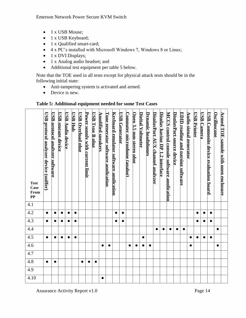
Note that the TOE used in all tests except for physical attack tests should be in the
following initial state:
Anti-tampering system is activated and armed.
Device is new.
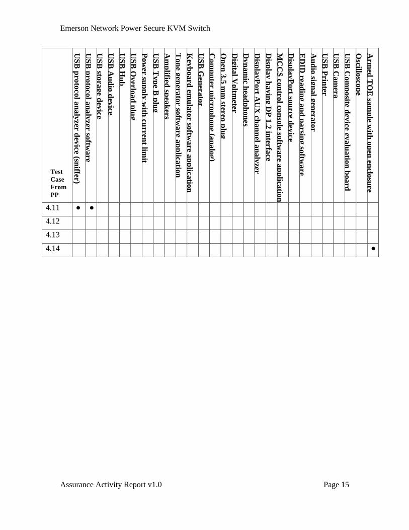
Table 5: Additional equipment needed for some Test Cases
Test
Case
From
PP U
SB
pro
toco
l an
aly
zer dev
ice (sniffe
r)
US
B p
roto
col a
naly
zer softw
are
US
B sto
rage d
evice
US
B A
ud
io d
evice
US
B H
ub
US
B O
verlo
ad
plu
g
Pow
er sup
ply
with
curren
t limit
US
B T
yp
e B p
lug
Am
plified
spea
kers
Ton
e gen
erato
r softw
are a
pp
licatio
n
Key
board
emu
lato
r softw
are a
pp
licatio
n
US
B G
enera
tor
Com
pu
ter mic
rop
hon
e (an
alo
g)
Op
en 3
.5 m
m stereo
plu
g
Dig
ital V
oltm
eter
Dyn
am
ic hea
dp
hon
es
Disp
layP
ort A
UX
chan
nel a
naly
zer
Disp
lay h
avin
g D
P 1
.2 in
terface
MC
CS
con
trol co
nso
le softw
are a
pp
licatio
n
Disp
layP
ort so
urce d
evice
ED
ID rea
din
g a
nd
parsin
g so
ftware
Au
dio
sign
al g
enera
tor
US
B P
rinter
US
B C
am
era
US
B C
om
posite d
evice ev
alu
atio
n b
oard
Oscillo
scop
e
Arm
ed T
OE
sam
ple w
ith o
pen
enclo
sure
4.1
4.2 ● ● ● ● ● ● ● ● ● ●
4.3 ● ● ● ● ● ● ● ● ● ●
4.4 ● ● ● ● ● ●
4.5 ● ● ● ● ● ● ● ● ● ●
4.6 ● ● ● ● ● ● ● ●
4.7
4.8 ● ● ● ● ●
4.9
4.10 ●
Emerson Network Power Secure KVM Switch
Assurance Activity Report v1.0 Page 15
Test
Case
From
PP
US
B p
roto
col a
naly
zer dev
ice (sniffe
r)
US
B p
roto
col a
naly
zer softw
are
US
B sto
rage d
evice
US
B A
ud
io d
evice
US
B H
ub
US
B O
verlo
ad
plu
g
Pow
er sup
ply
with
curren
t limit
US
B T
yp
e B p
lug
Am
plified
spea
kers
Ton
e gen
erato
r softw
are a
pp
licatio
n
Key
board
emu
lato
r softw
are a
pp
licatio
n
US
B G
enera
tor
Com
pu
ter mic
rop
hon
e (an
alo
g)
Op
en 3
.5 m
m stereo
plu
g
Dig
ital V
oltm
eter
Dyn
am
ic hea
dp
hon
es
Disp
layP
ort A
UX
chan
nel a
naly
zer
Disp
lay h
avin
g D
P 1
.2 in
terface
MC
CS
con
trol co
nso
le softw
are a
pp
licatio
n
Disp
layP
ort so
urce d
evice
ED
ID rea
din
g a
nd
parsin
g so
ftware
Au
dio
sign
al g
enera
tor
US
B P
rinter
US
B C
am
era
US
B C
om
posite d
evice ev
alu
atio
n b
oard
Oscillo
scop
e
Arm
ed T
OE
sam
ple w
ith o
pen
enclo
sure
4.11 ● ●
4.12
4.13
4.14 ●
Emerson Network Power Secure KVM Switch
Assurance Activity Report v1.0 Page 16
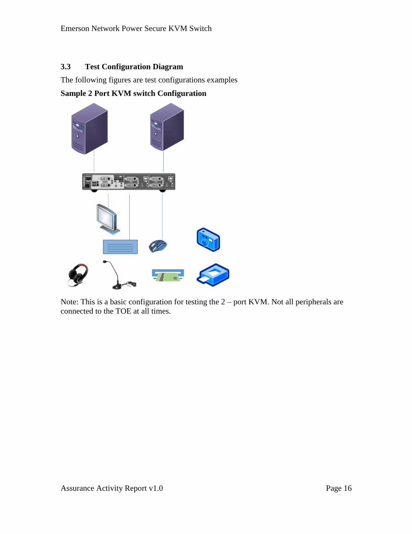
3.3 Test Configuration Diagram
The following figures are test configurations examples
Sample 2 Port KVM switch Configuration
Note: This is a basic configuration for testing the 2 – port KVM. Not all peripherals are
connected to the TOE at all times.
Emerson Network Power Secure KVM Switch
Assurance Activity Report v1.0 Page 17
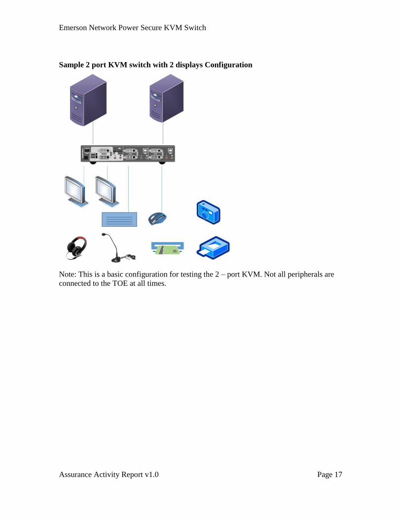
Sample 2 port KVM switch with 2 displays Configuration
Note: This is a basic configuration for testing the 2 – port KVM. Not all peripherals are
connected to the TOE at all times.
Emerson Network Power Secure KVM Switch
Assurance Activity Report v1.0 Page 18
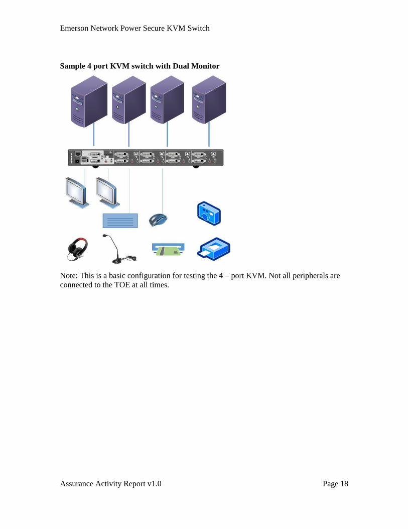
Sample 4 port KVM switch with Dual Monitor
Note: This is a basic configuration for testing the 4 – port KVM. Not all peripherals are
connected to the TOE at all times.
Emerson Network Power Secure KVM Switch
Assurance Activity Report v1.0 Page 19
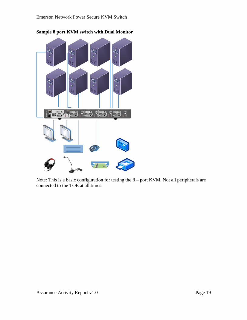
Sample 8 port KVM switch with Dual Monitor
Note: This is a basic configuration for testing the 8 – port KVM. Not all peripherals are
connected to the TOE at all times.
Emerson Network Power Secure KVM Switch
Assurance Activity Report v1.0 Page 20
4 Assurance Activities for PSS PP
4.1 FDP_IFC.1 (1) Subset information flow control
FDP_IFC.1.1 (1) The TSF shall enforce the [User Data Protection SFP] on
[Subjects: TOE computer interfaces, TOE peripheral device
interfaces
Information: User data transiting the TOE
Operations: Data flow between subjects].
Assurance Activity
Assurance Activities for this SFR were integrated with the Data Isolation Requirements
SFR below.
TSS Verification
Verify that the ST identifies subjects, information, and operations identified in the SFR.
CSC: It is stated in Section 7.1, in the first bulleted list, Bullet A identifies the
keyboard and mouse USB device emulators as the peripheral interfaces. The
computer interfaces are identified in Bullet C as host (computer) emulators. The
bulleted list also discusses the rules for data transiting the TOE between the
mouse and keyboard emulators and the computer interfaces (host emulators).
Operational Guidance Verification
CSC: Operational Guidance analysis was conducted in the Data Isolation
Requirements SFR below as required by the Assurance Activity.
Testing Summary
CSC: Testing was conducted in the Data Isolation Requirements SFR below as
required by the Assurance Activity.
Emerson Network Power Secure KVM Switch
Assurance Activity Report v1.0 Page 21
4.2 FDP_IFF.1 (1) Simple security attributes
Security Target
FDP_IFF.1.1 (1) The TSF shall enforce the [User Data Protection SFP] based on the
following types of subject and information security attributes:
[Subject: TOE computer interfaces
Subject security attributes: user selected computer interface
Subject: TOE peripheral device interfaces
Subject security attributes: none
Information: User data transiting the TOE
Information security attributes: none].
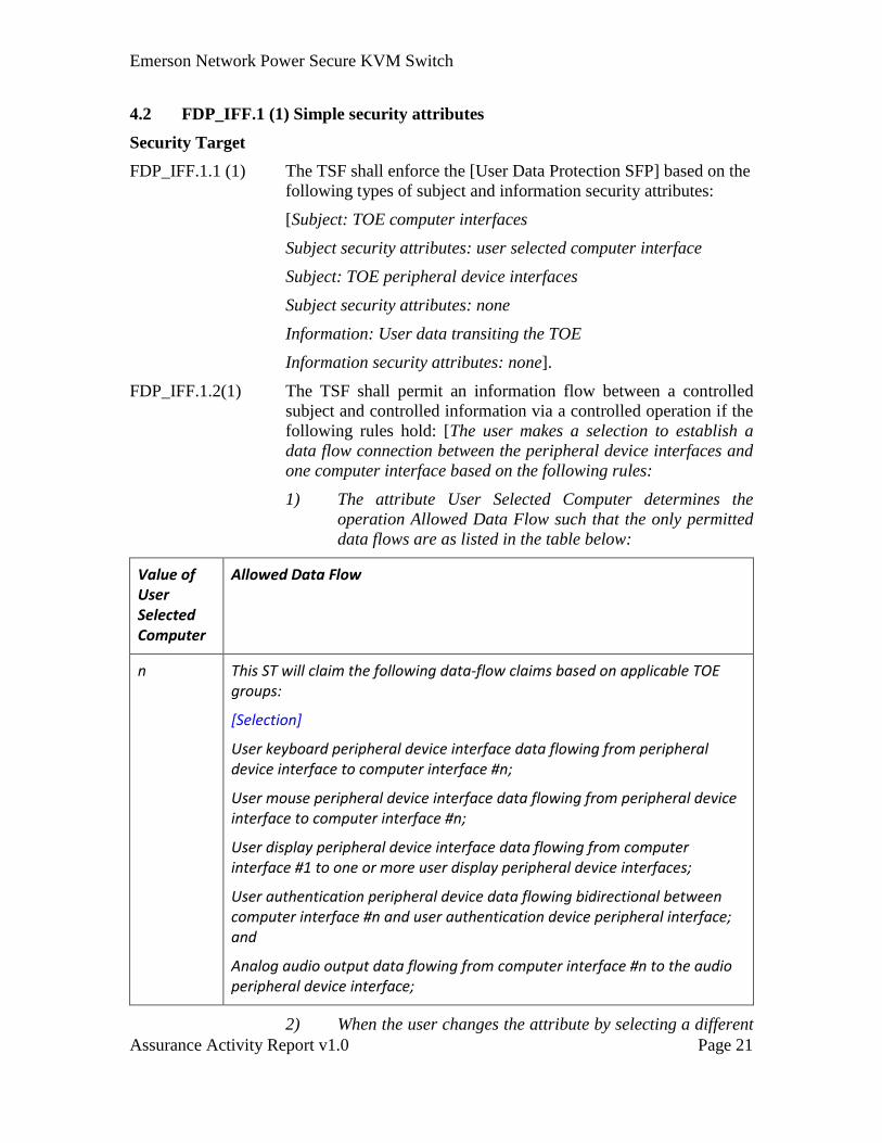
FDP_IFF.1.2(1) The TSF shall permit an information flow between a controlled
subject and controlled information via a controlled operation if the
following rules hold: [The user makes a selection to establish a
data flow connection between the peripheral device interfaces and
one computer interface based on the following rules:
1) The attribute User Selected Computer determines the
operation Allowed Data Flow such that the only permitted
data flows are as listed in the table below:
Value of User Selected Computer
Allowed Data Flow
n This ST will claim the following data-flow claims based on applicable TOE groups:
[Selection]
User keyboard peripheral device interface data flowing from peripheral device interface to computer interface #n;
User mouse peripheral device interface data flowing from peripheral device interface to computer interface #n;
User display peripheral device interface data flowing from computer interface #1 to one or more user display peripheral device interfaces;
User authentication peripheral device data flowing bidirectional between computer interface #n and user authentication device peripheral interface; and
Analog audio output data flowing from computer interface #n to the audio peripheral device interface;
2) When the user changes the attribute by selecting a different
Emerson Network Power Secure KVM Switch
Assurance Activity Report v1.0 Page 22
computer, this causes the TOE to change the data flow
accordingly.
3) The specific TOE implementation may allow splitting of the
user control to different shared peripheral groups. For
example, the user authentication device selected computer
may be #2, while the keyboard and mouse selected
computer device may be #1. In this case, each selection
shall be clearly indicated.
4) The TOE may support multiple instances of the peripheral
devices shown in the table above, or a subset of these
peripheral devices.]
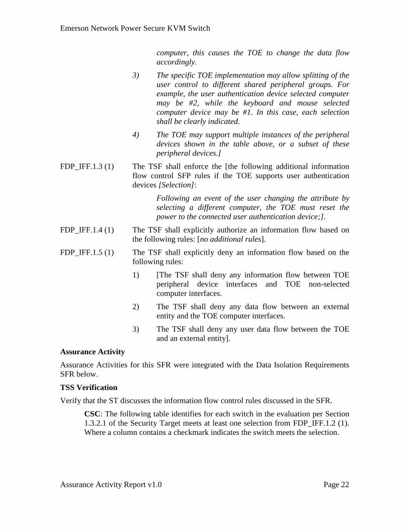
FDP_IFF.1.3 (1) The TSF shall enforce the [the following additional information
flow control SFP rules if the TOE supports user authentication
devices [Selection]:
Following an event of the user changing the attribute by
selecting a different computer, the TOE must reset the
power to the connected user authentication device;].
FDP_IFF.1.4 (1) The TSF shall explicitly authorize an information flow based on
the following rules: [no additional rules].
FDP_IFF.1.5 (1) The TSF shall explicitly deny an information flow based on the
following rules:
1) [The TSF shall deny any information flow between TOE
peripheral device interfaces and TOE non-selected
computer interfaces.
2) The TSF shall deny any data flow between an external
entity and the TOE computer interfaces.
3) The TSF shall deny any user data flow between the TOE
and an external entity].
Assurance Activity
Assurance Activities for this SFR were integrated with the Data Isolation Requirements
SFR below.
TSS Verification
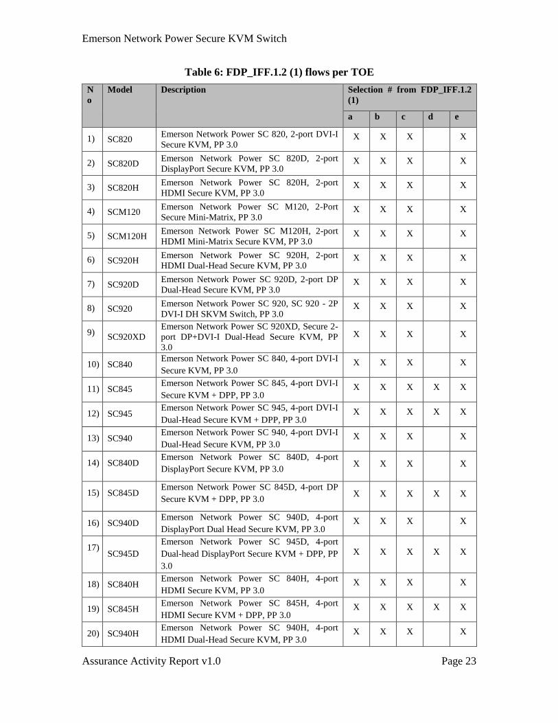
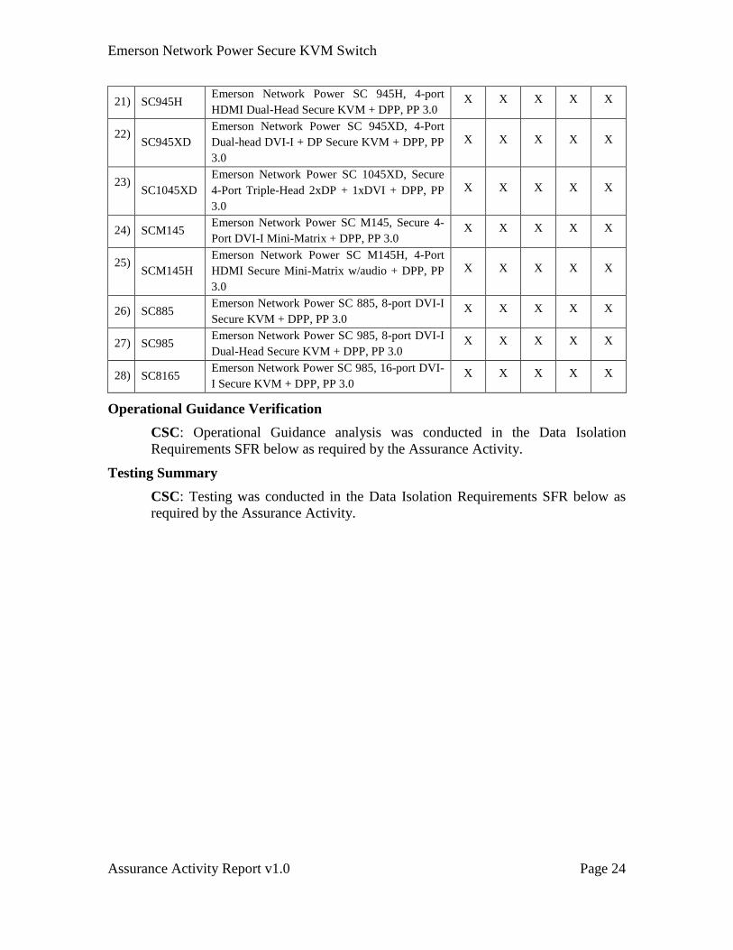
Verify that the ST discusses the information flow control rules discussed in the SFR.
CSC: The following table identifies for each switch in the evaluation per Section
1.3.2.1 of the Security Target meets at least one selection from FDP_IFF.1.2 (1).
Where a column contains a checkmark indicates the switch meets the selection.
Emerson Network Power Secure KVM Switch
Assurance Activity Report v1.0 Page 23
Table 6: FDP_IFF.1.2 (1) flows per TOE
N
o
Model Description Selection # from FDP_IFF.1.2
(1)
a b c d e
1) SC820 Emerson Network Power SC 820, 2-port DVI-I
Secure KVM, PP 3.0 X X X X
2) SC820D Emerson Network Power SC 820D, 2-port
DisplayPort Secure KVM, PP 3.0 X X X X
3) SC820H Emerson Network Power SC 820H, 2-port
HDMI Secure KVM, PP 3.0 X X X X
4) SCM120 Emerson Network Power SC M120, 2-Port
Secure Mini-Matrix, PP 3.0 X X X X
5) SCM120H Emerson Network Power SC M120H, 2-port
HDMI Mini-Matrix Secure KVM, PP 3.0 X X X X
6) SC920H Emerson Network Power SC 920H, 2-port
HDMI Dual-Head Secure KVM, PP 3.0 X X X X
7) SC920D Emerson Network Power SC 920D, 2-port DP
Dual-Head Secure KVM, PP 3.0 X X X X
8) SC920 Emerson Network Power SC 920, SC 920 - 2P
DVI-I DH SKVM Switch, PP 3.0 X X X X
9) SC920XD
Emerson Network Power SC 920XD, Secure 2-
port DP+DVI-I Dual-Head Secure KVM, PP
3.0
X X X X
10) SC840 Emerson Network Power SC 840, 4-port DVI-I
Secure KVM, PP 3.0 X X X X
11) SC845 Emerson Network Power SC 845, 4-port DVI-I
Secure KVM + DPP, PP 3.0 X X X X X
12) SC945 Emerson Network Power SC 945, 4-port DVI-I
Dual-Head Secure KVM + DPP, PP 3.0 X X X X X
13) SC940 Emerson Network Power SC 940, 4-port DVI-I
Dual-Head Secure KVM, PP 3.0 X X X X
14) SC840D Emerson Network Power SC 840D, 4-port
DisplayPort Secure KVM, PP 3.0 X X X X
15) SC845D Emerson Network Power SC 845D, 4-port DP
Secure KVM + DPP, PP 3.0 X X X X X
16) SC940D Emerson Network Power SC 940D, 4-port
DisplayPort Dual Head Secure KVM, PP 3.0 X X X X
17) SC945D
Emerson Network Power SC 945D, 4-port
Dual-head DisplayPort Secure KVM + DPP, PP
3.0
X X X X X
18) SC840H Emerson Network Power SC 840H, 4-port
HDMI Secure KVM, PP 3.0 X X X X
19) SC845H Emerson Network Power SC 845H, 4-port
HDMI Secure KVM + DPP, PP 3.0 X X X X X
20) SC940H Emerson Network Power SC 940H, 4-port
HDMI Dual-Head Secure KVM, PP 3.0 X X X X
Emerson Network Power Secure KVM Switch
Assurance Activity Report v1.0 Page 24
21) SC945H Emerson Network Power SC 945H, 4-port
HDMI Dual-Head Secure KVM + DPP, PP 3.0 X X X X X
22) SC945XD
Emerson Network Power SC 945XD, 4-Port
Dual-head DVI-I + DP Secure KVM + DPP, PP
3.0
X X X X X
23) SC1045XD
Emerson Network Power SC 1045XD, Secure
4-Port Triple-Head 2xDP + 1xDVI + DPP, PP
3.0
X X X X X
24) SCM145 Emerson Network Power SC M145, Secure 4-
Port DVI-I Mini-Matrix + DPP, PP 3.0 X X X X X
25) SCM145H
Emerson Network Power SC M145H, 4-Port
HDMI Secure Mini-Matrix w/audio + DPP, PP
3.0
X X X X X
26) SC885 Emerson Network Power SC 885, 8-port DVI-I
Secure KVM + DPP, PP 3.0 X X X X X
27) SC985 Emerson Network Power SC 985, 8-port DVI-I
Dual-Head Secure KVM + DPP, PP 3.0 X X X X X
28) SC8165 Emerson Network Power SC 985, 16-port DVI-
I Secure KVM + DPP, PP 3.0 X X X X X
Operational Guidance Verification
CSC: Operational Guidance analysis was conducted in the Data Isolation
Requirements SFR below as required by the Assurance Activity.
Testing Summary
CSC: Testing was conducted in the Data Isolation Requirements SFR below as
required by the Assurance Activity.
Emerson Network Power Secure KVM Switch
Assurance Activity Report v1.0 Page 25
4.3 FDP_IFC.1 (2) Subset information flow control
Security Target
FDP_IFC.1.1 (2) The TSF shall enforce the [Data Isolation SFP] on
[Subjects: TOE computer interfaces, TOE peripheral interfaces
Information: data transiting the TOE
Operations: data flows between computer interfaces].
Assurance Activity
This Assurance Activity is combined with FDP_IFF.1 (2).
4.4 FDP_IFF.1 (2) Simple security attributes
Security Target
FDP_IFF.1.1 (2) The TSF shall enforce the [Data Isolation SFP] based on the
following types of subject and information security attributes:
[Subject: TOE interfaces
Subject security attributes: Interface types (Allowed TOE
interface types are listed in Annex C of this PP. Power source and
connected computer interfaces are also applicable interface types.)
Subject: TOE peripheral device interfaces
Subject security attributes: none
Information: data transiting the TOE
Information security attributes: data types. (The TSF will
enforce the data isolation SFP on the following data types:
a. User keyboard key codes;
b. User pointing device commands;
c. Video information (User display video data and display
management data);
d. Audio output data; and
e. User authentication device data.)].
FDP_IFF.1.2 (2) The TSF shall permit an information flow between a controlled
subject and controlled information via a controlled operation if the
following rules hold:
1) [During normal TOE operation, the TSF shall permit only
user entered keyboard key codes, and user input mouse
commands to flow between the TOE keyboard and mouse
peripheral device interfaces and the TOE selected
computer interface. No flow is permitted between the
selected computer interface and the TOE keyboard and
Emerson Network Power Secure KVM Switch
Assurance Activity Report v1.0 Page 26
mouse peripheral device interfaces.
2) The TSF shall permit information flow and TSF resources
sharing between two TOE user peripheral interfaces of the
same Shared Peripheral group].
FDP_IFF.1.3 (2) The TSF shall enforce the [No additional rules].
FDP_IFF.1.4 (2) The TSF shall explicitly authorize an information flow based on
the following rules: [No additional rules].
FDP_IFF.1.5 (2) The TSF shall explicitly deny an information flow based on the
following rules:
[1. The TSF will deny any information flow between TOE Computer
Interfaces, except those allowed by the User Data Flow rules;
2. The TSF will deny data flow other than keyboard entries and mouse
reports between the TOE keyboard and mouse peripheral device
interfaces and the TOE selected computer interface;
3. The TSF will deny power flow between the selected computer
interface and TOE keyboard and mouse peripheral device
interfaces;
4. The TSF will deny information flow from the TOE selected computer
interface to the TOE keyboard and mouse peripheral device
interface;
5. The TSF will deny data flow of user authentication device data
transiting the TOE to non-selected TOE computer interfaces;
6. The TSF will assure that the user authentication device computer
interfaces are not shared with any other TOE peripheral function
interface (keyboard, mouse etc.);
7. The TSF will deny information flow between two TOE user
peripheral interfaces in different Shared Peripheral groups;
8. The TSF will deny analog audio information flow between the TOE
selected computer audio interface and the user audio device
peripheral interface when a microphone peripheral device is
intentionally or unintentionally connected to the TOE audio
peripheral device interface;
9. The TSF will enforce unidirectional information flow between the
TOE selected computer audio interface and the user audio device
peripheral interface. Bidirectional information flow shall be
denied;
10. The TSF will deny all AUX Channel information flows other than
link negotiation, link training and EDID reading;
11. The TSF will deny any information flow from the TOE display
peripheral device interface and the selected computer interface
Emerson Network Power Secure KVM Switch
Assurance Activity Report v1.0 Page 27
with the exception of EDID information that may be passed once
at TOE power up or after recovery from TOE reset;
12. The TSF will deny an information flow between the selected
computer display interface and the TOE display peripheral device
interface on the EDID channel;
13. The TSF will recognize and enable only those peripherals with an
authorized interface type as defined in Annex C of this PP.
Information flow to all other peripherals will be denied; and
14. All denied information flows will also be denied when the TOE’s
power source is removed]
Assurance Activity
TSS
The evaluator shall verify that the TOE Summary Specification (TSS) describes all of the
interfaces supported in each port group. Any options to switch peripherals independently
from the keyboard and mouse must be described.
The evaluator shall also verify that the TSS lists and describes all TOE control options.
To improve USB data analysis, prior to the following tests, the evaluator shall receive a
full list of all USB endpoints used by the TOE, and their specific functions.
The evaluator shall verify that the TSS describes all of the external interfaces supported
by the TOE and that there are no external interfaces other than computer interfaces,
power interfaces and peripheral device interfaces. Any wireless or wired interface must
be fully described with its intended function.
The evaluator shall verify that the TSS describes all of the interfaces supported in each
port group.
Any options to switch peripherals independently from the keyboard and mouse must be
described.
The evaluator shall examine the TSS and verify that for any human interface device that
may be switched independently from the keyboard and mouse, there is a description that
explains how this interface is isolated from all other device interfaces. The evaluator shall
be able to determine from this description that there are no shared components, shared
lines or shared power supplies.
The evaluator shall verify that the TSS provides details about supported user
authentication devices. TSS shall also indicate whether the user authentication device is
emulated by the TOE or switched.
The evaluator shall examine the TSS to verify that it describes how the user
authentication data path is isolated from all other data paths. This section must indicate
that the data path used by the user authentication device is not shared with other transiting
data. This section must also describe how the USB port for the user authentication device
is powered separately from other peripheral device functions.

Emerson Network Power Secure KVM Switch
Assurance Activity Report v1.0 Page 28
[Conditional – not applicable for the TOE] If the TOE includes an integrated user
authentication device, the evaluator shall examine the TSS to verify that is describes:
1) How the user authentication data path is isolated from all other data paths;
2) If the user authentication device is emulated by the PSS or not;
3) If the user authentication device is emulated, then the TSS shall include detailed
information describing authentication session termination by the user, and
describe how this occurs simultaneously in all connected computers.
[Conditional – not applicable – all DisplayPort KVM TOE support only HDMI
display] If the TOE supports DisplayPort video –
The evaluator shall verify that the TSS describes how the TOE video auxiliary channel
(AUX) path blocks information flows other than the minimal set required to establish the
video link. The description should discuss the method implemented to prevent
unauthorized DisplayPort transactions:
The TOE prevents the DisplayPort AUX channel link from reaching speeds
higher than 1 megabits per second (DisplayPort ver 1.2 or higher) while blocking
MCCS transactions; or
The TOE disassembles the DisplayPort AUX channel transactions to block all
unauthorized transactions.
Guidance
The evaluator shall verify that the operational guidance provides clear direction for the
connection of computers and peripheral devices to the TOE. Any options to switch
peripheral devices independently from the keyboard and mouse must be described,
including a description of how this switching is indicated on the PSS.
The evaluator shall verify that the operational guidance provides clear direction for the
usage and connection of TOE interfaces. General information may be provided for
computer, power and peripheral devices. Any wireless or wired interface that receives or
transmits data to or from the TOE must be described in sufficient detail to allow the
evaluator to determine if there is a risk that these interfaces could be misused to import or
export user data.
The evaluator shall examine the user guidance and verify that the guidance provides users
with information on how to recognize a device where the anti-tampering functionality has
been activated. The evaluator shall review the following subjects in the user and
administrative guidance to verify that there are no processes or settings that may allow
any forbidden data flow between objects:
a) Installation options;
b) TOE configurations:
c) TOE firmware options; or
d) Accessories supplied with TOE
Emerson Network Power Secure KVM Switch
Assurance Activity Report v1.0 Page 29
The evaluator shall verify that any cables or accessories supplied with the TOE (as
described in the guidance) do not support computer interface types in the following
prohibited protocols list:
a) Microphone audio input;
b) Line in audio input;
c) DockPort;
d) USB docking;
e) Thunderbolt; or
f) Other docking protocols.
The evaluator shall verify that the supported peripheral devices and protocols match the
information in Annex C of this PP.
The evaluator shall examine the TOE user guidance to determine if there are any
operating modes that allow peripheral devices to be switched independently from the
keyboard and mouse. All such operating modes must be covered in the TSS. The
evaluator shall examine the TOE guidance and verify that the TOE does not support
microphone or audio line input device interfaces. The evaluator shall also examine the
TOE guidance and verify that it includes an explicit warning not to use microphone, line
input or headset devices with the TOE.
Tests
1) Since a PSS typically has a large set of switched peripheral devices and connected
computers, in order to prevent duplication of test setup and testing effort, several
tests were grouped into larger test sets. The selection of the appropriate test set is
based on the specific TOE implementation, which is based on the type of
peripheral devices being supported.
2) Each port group switch selection must be tested for each device; however, not all
port groups must be connected simultaneously. For example, if testing a 16-port
device, the evaluator may use four connected computers, but must change the
connected ports several times to ensure all computer port group connections and
switch selections are tested. Likewise, a single USB protocol analyzer may be
used, but must be moved to test each applicable port. Several of the tests are
written assuming a 4 port device. Each test must be adapted to accommodate all
of the ports on each tested TOE.
3) The tests assume the use of Windows on each connected computer. It is
permissible to perform the tests using Linux based connected machines with
similar applications installed.
4) The evaluator is expected to prepare an image or bitmap with an easily visible
number to be used as a background for each connected computer in order to
identify each channel (e.g., a white background with the number 1 may serve as a
desktop background for computer #1.)
5) Note that some of the following tests require knowledge of the USB protocol to
Emerson Network Power Secure KVM Switch
Assurance Activity Report v1.0 Page 30
properly configure and operate a USB protocol analyzer and USB sniffer.
Evaluation Note: The actual tests in the Protection Profile Sections 4.2.10 –
4.2.20 were not reproduced for brevity. In the actual tests for this SFR, the test
steps are reproduced from the PP.
TSS Verification
The evaluator shall verify that the TOE Summary Specification (TSS) describes all of the
interfaces supported in each port group. Any options to switch peripherals independently
from the keyboard and mouse must be described.
CSC: Tables 4 and 5 of the ST describes the protocols supported for each of the
switches for each of the computer ports. For example, the first switch, SC820,
supports USB 1.1/2.0 console keyboard and mouse, audio and video with the
interfaces supporting analog stereo in and DVI-I.
The evaluator shall also verify that the TSS lists and describes all TOE control options.
CSC: Table 4 identifies specifically, per switch, what is supported by the console
port group. The keyboard, mouse, audio, and display peripherals are identified for
each switch.
To improve USB data analysis, prior to the following tests, the evaluator shall receive a
full list of all USB endpoints used by the TOE, and their specific functions.
The evaluator shall verify that the TSS describes all of the external interfaces supported
by the TOE and that there are no external interfaces other than computer interfaces,
power interfaces and peripheral device interfaces. Any wireless or wired interface must
be fully described with its intended function.
CSC: Tables 4 and 5 details what interfaces and protocols are supported for each
switch for the computer ports and the console ports. Table 3 of the ST list the
peripheral devices supported by the TOE. The evaluator received a full list of all
USB endpoints used by the TOE – an empty list. No internal hub or endpoints
listed in that list.
The application note for FDP_IFF.1.1(2) also states the interfaces not supported including
Microphone audio input, DockPort, USB Docking, Thunderbolt, and other docking
protocols.
The evaluator shall verify that the TSS describes all of the interfaces supported in each
port group.
CSC: Tables 4 and 5 details what interfaces and protocols are supported for each
switch for the computer ports and the console ports.
Any options to switch peripherals independently from the keyboard and mouse must be
described.
CSC: There are no options to switch peripherals independently from the keyboard
and mouse. Each peripheral group is powered by the connected group computer
and sits behind a one way data diode. When a computer is selected, all peripherals
in that group are selected. See Section 7.1 of the ST.
Emerson Network Power Secure KVM Switch
Assurance Activity Report v1.0 Page 31
The evaluator shall examine the TSS and verify that for any human interface device that
may be switched independently from the keyboard and mouse, there is a description that
explains how this interface is isolated from all other device interfaces.
CSC: There is no option to switch other devices independently from the keyboard
and mouse.
The evaluator shall be able to determine from this description that there are no shared
components, shared lines or shared power supplies.
CSC: Section 7.1 describe the isolation requirements behind emulators (which are
microcontrollers for each port group) to prevent peripherals from having direct
access to computer ports. Each device emulator is powered by its own connected
computer. Power domains of different computer interfaces are completely
independent and isolated behind unidirectional data diodes. Optical Isolators for
each channel were visible on the exposed PCBAs used for some testing.
The evaluator shall verify that the TSS provides details about supported user
authentication devices. TSS shall also indicate whether the user authentication device is
emulated by the TOE or switched.
CSC: Section 7.5, states the details about supported user authentication devices,
“Standard smart-card reader USB token or biometric authentication device having
USB smart-card class interface complying with USB Organization standard CCID
Revision 1.1 or ICCID Revision 1.0.” Table 7 of this document identifies the TOE
having this function.
Section 7.5, the DPP function, bullet h states, “The TOE does not emulate or
process user authentication device data. No data retention is possible.”
The evaluator shall examine the TSS to verify that it describes how the user
authentication data path is isolated from all other data paths. This section must indicate
that the data path used by the user authentication device is not shared with other transiting
data. This section must also describe how the USB port for the user authentication device
is powered separately from other peripheral device functions.
CSC: Section 7.5, bullets a) and b) describe each (dedicated peripheral port) DPP
computer interface as using independent circuitry and power planes. There is no
shared circuitry or logical functions with other ports or other TOE functions. The
user authentication device data paths in the TOE are fully isolated from all other
user data paths and functions.
If the TOE includes an integrated user authentication device, the evaluator shall examine
the TSS to verify that is describes:
1) How the user authentication data path is isolated from all other data paths;
2) If the user authentication device is emulated by the PSS or not;
3) If the user authentication device is emulated, then the TSS shall include detailed
information describing authentication session termination by the user, and
describe how this occurs simultaneously in all connected computers.
CSC: None of the evaluated switches has a built-in user authentication device.

Emerson Network Power Secure KVM Switch
Assurance Activity Report v1.0 Page 32
The evaluator shall verify that the TSS describes how the TOE video auxiliary channel
(AUX) path blocks information flows other than the minimal set required to establish the
video link. The description should discuss the method implemented to prevent
unauthorized DisplayPort transactions:
The TOE prevents the DisplayPort AUX channel link from reaching speeds
higher than 1 megabits per second (DisplayPort ver 1.2 or higher) while blocking
MCCS transactions; or
The TOE disassembles the DisplayPort AUX channel transactions to block all
unauthorized transactions.
CSC: Section 7.5, bullet d, details the DisplayPort requirements for the switches
that support DisplayPort video. The TOE follows the second option in the two
bullets above. It disassembles the DP signal (by converting the AUX to raw video
+ I2C). From bullet f, “TOE video function filters the AUX channel by converting
it to I2C EDID only. DisplayPort video is converted into HDMI video stream and
I2C EDID lines that being connected to the same emulated EDID EEPROM
functions. All AUX channel threats are mitigated through the conversion from
DisplayPort to HDMI protocols. All types of traffic not authorized by the
referenced PP including USB, Ethernet, MCCS and EDID write are blocked by
this TOE function as the emulated EEPROM would only support valid EDID read
requests from connected computers.”
Operational Guidance Verification
The evaluator shall verify that the operational guidance provides clear direction for the
connection of computers and peripheral devices to the TOE. Any options to switch
peripheral devices independently from the keyboard and mouse must be described,
including a description of how this switching is indicated on the PSS.
CSC: The User Guidance provides clear direction for the connection of computer
and peripheral devices to the TOE through installation guides, precautions, and
pictures. It is also stated, “Product design achieves maximal security by keeping
the video path separate with keyboard and mouse switched together, purging
keyboard buffer when switching channels.”
The evaluator shall verify that the operational guidance provides clear direction for the
usage and connection of TOE interfaces. General information may be provided for
computer, power and peripheral devices.
CSC: Throughout each User Guidance there are Installation guides, Operational
guides and pictures to describe a clear direction for the usage and connection of
all TOE interfaces.
Any wireless or wired interface that receives or transmits data to or from the TOE must
be described in sufficient detail to allow the evaluator to determine if there is a risk that
these interfaces could be misused to import or export user data.
CSC: Each User Guidance Manual has warnings and precautions stating, “For
security reasons products do not support wireless keyboards and mice. In any case
do not connect wireless keyboard/mouse to product.”
Emerson Network Power Secure KVM Switch
Assurance Activity Report v1.0 Page 33
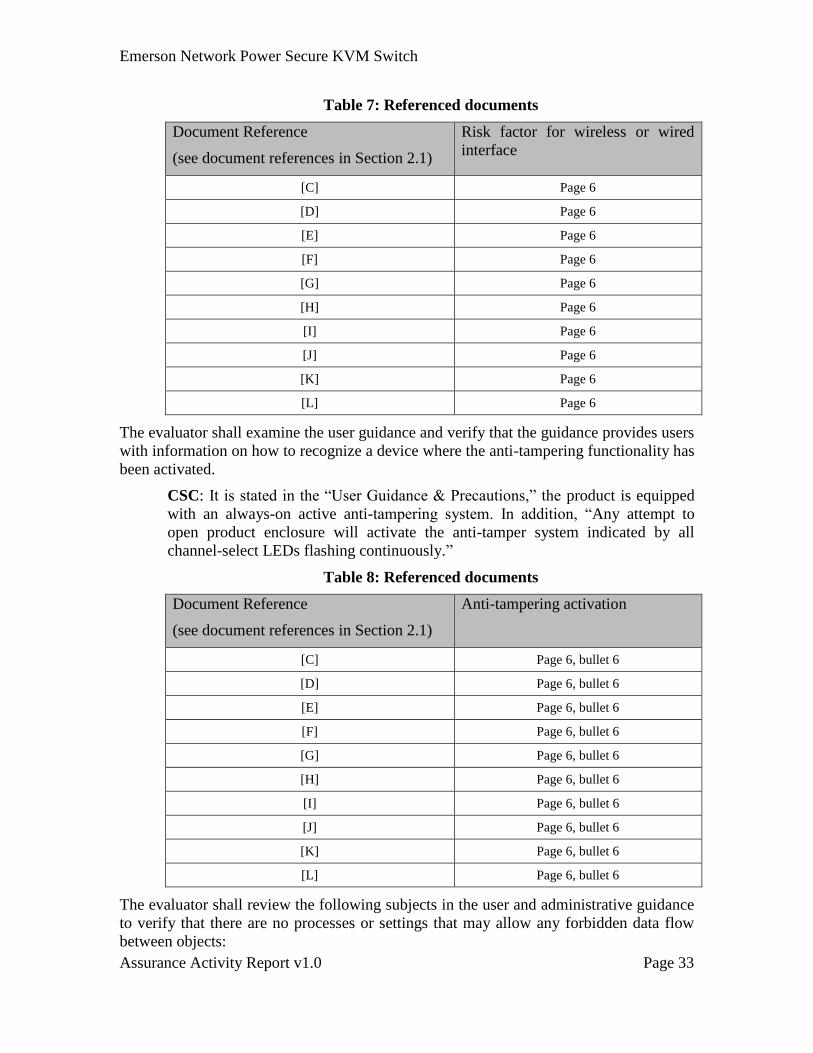
Table 7: Referenced documents
Document Reference
(see document references in Section 2.1)
Risk factor for wireless or wired
interface
[C] Page 6
[D] Page 6
[E] Page 6
[F] Page 6
[G] Page 6
[H] Page 6
[I] Page 6
[J] Page 6
[K] Page 6
[L] Page 6
The evaluator shall examine the user guidance and verify that the guidance provides users
with information on how to recognize a device where the anti-tampering functionality has
been activated.
CSC: It is stated in the “User Guidance & Precautions,” the product is equipped
with an always-on active anti-tampering system. In addition, “Any attempt to
open product enclosure will activate the anti-tamper system indicated by all
channel-select LEDs flashing continuously.”
Table 8: Referenced documents
Document Reference
(see document references in Section 2.1)
Anti-tampering activation
[C] Page 6, bullet 6
[D] Page 6, bullet 6
[E] Page 6, bullet 6
[F] Page 6, bullet 6
[G] Page 6, bullet 6
[H] Page 6, bullet 6
[I] Page 6, bullet 6
[J] Page 6, bullet 6
[K] Page 6, bullet 6
[L] Page 6, bullet 6
The evaluator shall review the following subjects in the user and administrative guidance
to verify that there are no processes or settings that may allow any forbidden data flow
between objects:
Emerson Network Power Secure KVM Switch
Assurance Activity Report v1.0 Page 34
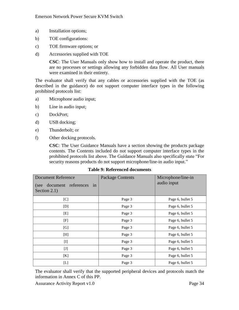
a) Installation options;
b) TOE configurations:
c) TOE firmware options; or
d) Accessories supplied with TOE
CSC: The User Manuals only show how to install and operate the product, there
are no processes or settings allowing any forbidden data flow. All User manuals
were examined in their entirety.
The evaluator shall verify that any cables or accessories supplied with the TOE (as
described in the guidance) do not support computer interface types in the following
prohibited protocols list:
a) Microphone audio input;
b) Line in audio input;
c) DockPort;
d) USB docking;
e) Thunderbolt; or
f) Other docking protocols.
CSC: The User Guidance Manuals have a section showing the products package
contents. The Contents included do not support computer interface types in the
prohibited protocols list above. The Guidance Manuals also specifically state “For
security reasons products do not support microphone/line-in audio input.”
Table 9: Referenced documents
Document Reference
(see document references in
Section 2.1)
Package Contents Microphone/line-in
audio input
[C] Page 3 Page 6, bullet 5
[D] Page 3 Page 6, bullet 5
[E] Page 3 Page 6, bullet 5
[F] Page 3 Page 6, bullet 5
[G] Page 3 Page 6, bullet 5
[H] Page 3 Page 6, bullet 5
[I] Page 3 Page 6, bullet 5
[J] Page 3 Page 6, bullet 5
[K] Page 3 Page 6, bullet 5
[L] Page 3 Page 6, bullet 5
The evaluator shall verify that the supported peripheral devices and protocols match the
information in Annex C of this PP.
Emerson Network Power Secure KVM Switch
Assurance Activity Report v1.0 Page 35
The evaluator shall examine the TOE user guidance to determine if there are any
operating modes that allow peripheral devices to be switched independently from the
keyboard and mouse.
CSC: There are no options to switches peripherals independently from the
keyboard and mouse. The documents were reviewed and no indication of other
operating modes is in the documents.
All such operating modes must be covered in the TSS.
CSC: Per the ST, there are no options to switches peripherals independently from
the keyboard and mouse.
The evaluator shall examine the TOE guidance and verify that the TOE does not support
microphone or audio line input device interfaces.
The evaluator shall also examine the TOE guidance and verified that it includes an
explicit warning not to use microphone, line input or headset devices with the TOE.
Emerson Network Power Secure KVM Switch
Assurance Activity Report v1.0 Page 36
CSC: Explicit warning found in all TOE guidance at the same locations indicated
in table 9 above. Text appearing in that bullet is: “For security reasons product do
not support microphone/line-in audio input. In any case do not connect a
microphone to product audio output port, including headsets.”
Testing Summary
Table 10: Applicable test setups
Test Setup TOE Model TOE Type
C SC920H Secure 2P KVM Switch
D SC945D Secure 4P KVM switch (DP)
F SCM145 Secure 4-port Mini-matrix
I SC885 Secure 8 port KVM
Assurance
Activity
Testing Summary
Test 4.1 – User
Control
This test is
mandatory for
all TOEs
claiming
compliance to
this PP.
General test setup from the PP, section 4.2.9, was followed to ensure the tests themselves
would be run according to the established procedures.
Section 4.2.10 of the PP were followed as prescribed, results are captured below in the
section marked “Actual Tests”.
The following chart indicates which models were tested by the evaluator:
Test Setup Part C D F I
Test 4.1 – User Control - ● ● ● ●
Notes / Justification:
Section 3.2 above identifies those additional items required to have the TOE in an
operational condition; those items were used for these tests.
No TOE tested failed any portion of the required steps set forth in the PP.
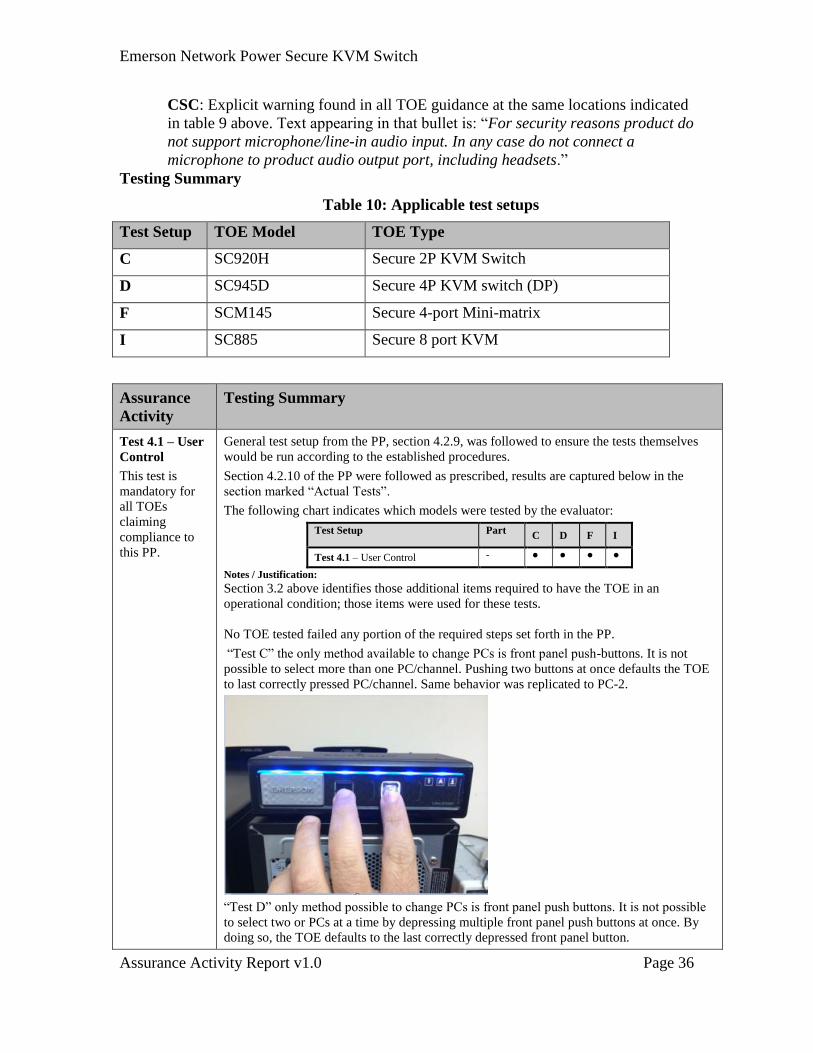
“Test C” the only method available to change PCs is front panel push-buttons. It is not
possible to select more than one PC/channel. Pushing two buttons at once defaults the TOE
to last correctly pressed PC/channel. Same behavior was replicated to PC-2.
“Test D” only method possible to change PCs is front panel push buttons. It is not possible
to select two or PCs at a time by depressing multiple front panel push buttons at once. By
doing so, the TOE defaults to the last correctly depressed front panel button.
Emerson Network Power Secure KVM Switch
Assurance Activity Report v1.0 Page 37
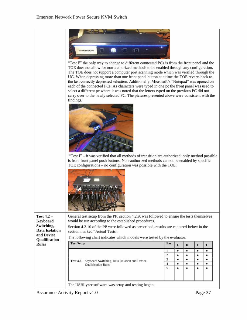
“Test F” the only way to change to different connected PCs is from the front panel and the
TOE does not allow for non-authorized methods to be enabled through any configuration.
The TOE does not support a computer port scanning mode which was verified through the
UG. When depressing more than one front panel button at a time the TOE reverts back to
the last correctly depressed selection. Additionally, Microsoft’s “Notepad” was opened on
each of the connected PCs. As characters were typed in one pc the front panel was used to
select a different pc where it was noted that the letters typed on the previous PC did not
carry over to the newly selected PC. The pictures presented above were consistent with the
findings.
“Test I” – it was verified that all methods of transition are authorized; only method possible
is from front panel push buttons. Non-authorized methods cannot be enabled by specific
TOE configurations – no configuration was possible with the TOE.
Test 4.2 –
Keyboard
Switching,
Data Isolation
and Device
Qualification
Rules
General test setup from the PP, section 4.2.9, was followed to ensure the tests themselves
would be run according to the established procedures.
Section 4.2.10 of the PP were followed as prescribed, results are captured below in the
section marked “Actual Tests”.
The following chart indicates which models were tested by the evaluator:
Test Setup Part C D F I
Test 4.2 – Keyboard Switching, Data Isolation and Device
Qualification Rules
1 ● ● ● ●
2 ● ● ● ●
3 ● ● ● ●
4 ● ● ● ●
5 ● ● ● ●
The USBLyzer software was setup and testing began.
Emerson Network Power Secure KVM Switch
Assurance Activity Report v1.0 Page 38
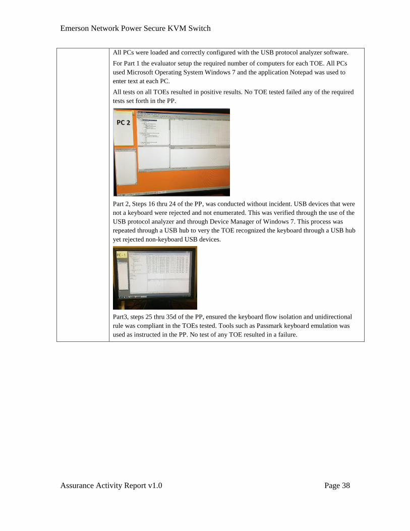
All PCs were loaded and correctly configured with the USB protocol analyzer software.
For Part 1 the evaluator setup the required number of computers for each TOE. All PCs
used Microsoft Operating System Windows 7 and the application Notepad was used to
enter text at each PC.
All tests on all TOEs resulted in positive results. No TOE tested failed any of the required
tests set forth in the PP.
Part 2, Steps 16 thru 24 of the PP, was conducted without incident. USB devices that were
not a keyboard were rejected and not enumerated. This was verified through the use of the
USB protocol analyzer and through Device Manager of Windows 7. This process was
repeated through a USB hub to very the TOE recognized the keyboard through a USB hub
yet rejected non-keyboard USB devices.
Part3, steps 25 thru 35d of the PP, ensured the keyboard flow isolation and unidirectional
rule was compliant in the TOEs tested. Tools such as Passmark keyboard emulation was
used as instructed in the PP. No test of any TOE resulted in a failure.
Emerson Network Power Secure KVM Switch
Assurance Activity Report v1.0 Page 39
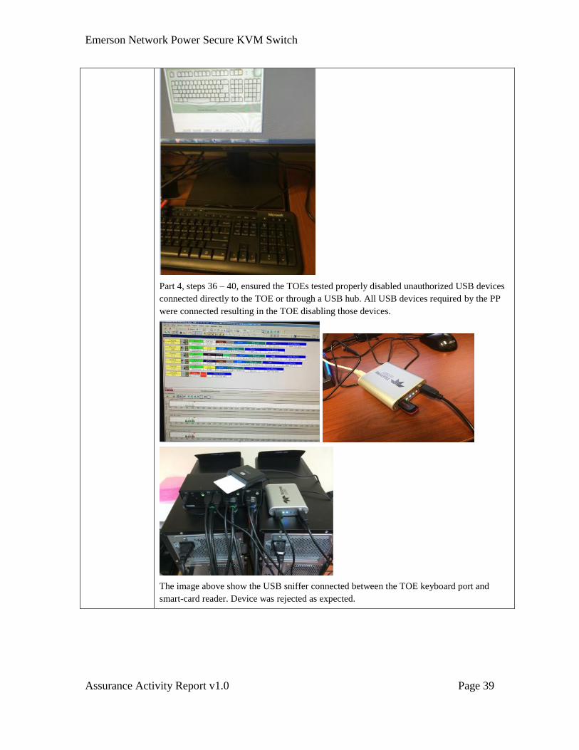
Part 4, steps 36 – 40, ensured the TOEs tested properly disabled unauthorized USB devices
connected directly to the TOE or through a USB hub. All USB devices required by the PP
were connected resulting in the TOE disabling those devices.
The image above show the USB sniffer connected between the TOE keyboard port and
smart-card reader. Device was rejected as expected.
Emerson Network Power Secure KVM Switch
Assurance Activity Report v1.0 Page 40
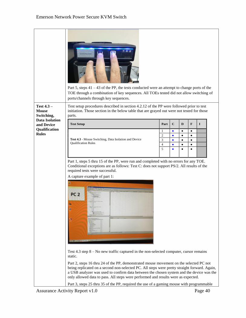
Part 5, steps 41 – 43 of the PP, the tests conducted were an attempt to change ports of the
TOE through a combination of key sequences. All TOEs tested did not allow switching of
ports/channels through key sequences.
Test 4.3 –
Mouse
Switching,
Data Isolation
and Device
Qualification
Rules
Test setup procedures described in section 4.2.12 of the PP were followed prior to test
initiation. Those section in the below table that are grayed out were not tested for those
parts.
Test Setup Part C D F I
Test 4.3 - Mouse Switching, Data Isolation and Device
Qualification Rules
1 ● ● ●
2 ● ● ●
3 ● ● ●
4 ● ● ●
5 ● ● ●
Part 1, steps 5 thru 15 of the PP, were run and completed with no errors for any TOE.
Conditional exceptions are as follows: Test C: does not support PS/2. All results of the
required tests were successful.
A capture example of part 1:
Test 4.3 step 8 – No new traffic captured in the non-selected computer, cursor remains
static.
Part 2, steps 16 thru 24 of the PP, demonstrated mouse movement on the selected PC not
being replicated on a second non-selected PC. All steps were pretty straight forward. Again,
a USB analyzer was used to confirm data between the chosen system and the device was the
only allowed data to pass. All steps were performed and results were as expected.
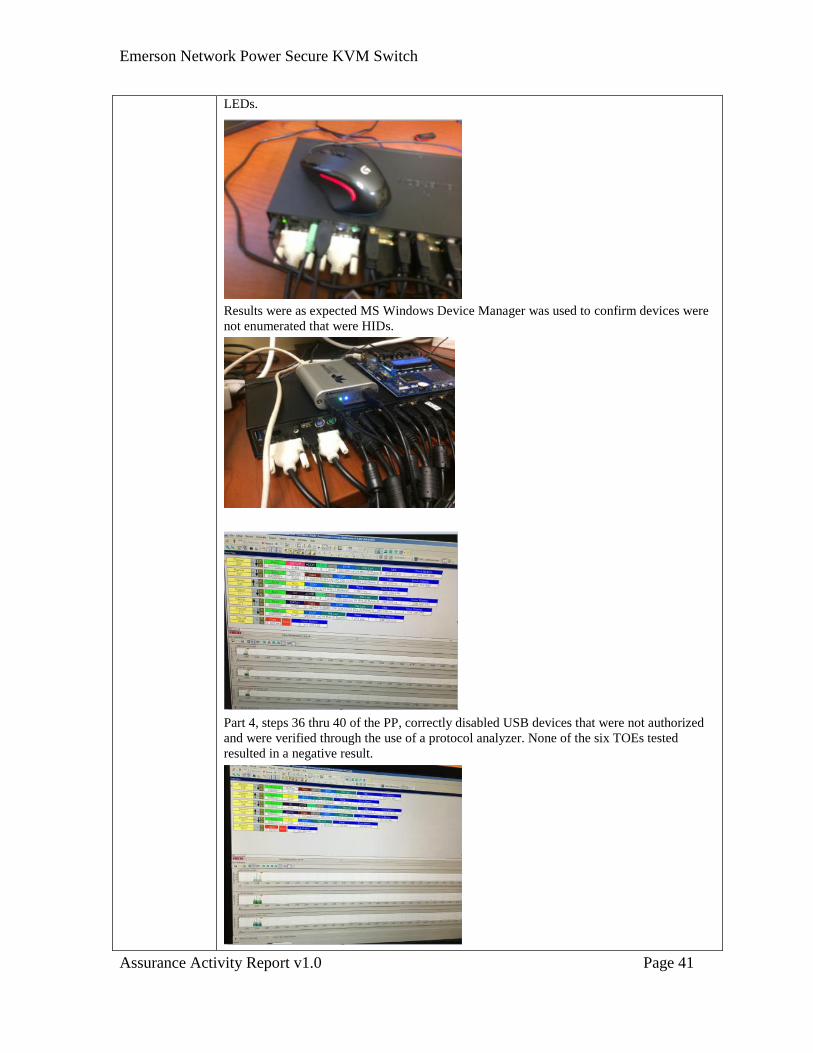
Part 3, steps 25 thru 35 of the PP, required the use of a gaming mouse with programmable
Emerson Network Power Secure KVM Switch
Assurance Activity Report v1.0 Page 41
LEDs.
Results were as expected MS Windows Device Manager was used to confirm devices were
not enumerated that were HIDs.
Part 4, steps 36 thru 40 of the PP, correctly disabled USB devices that were not authorized
and were verified through the use of a protocol analyzer. None of the six TOEs tested
resulted in a negative result.
Emerson Network Power Secure KVM Switch
Assurance Activity Report v1.0 Page 42
Part 5, steps 41 thru 43 of the PP, mouse data flow was isolated to only the chosen PC. This
was verified through the use of a USB protocol analyzer.
Overall no negative results were experienced all TOEs tested functioned as expected.
Test 4.4 –
Display
Switching,
Data Isolation
and
Unidirectional
Flow Rules
Test setup procedures described in section 4.2.13 of the PP were followed prior to test
initiation.
Test Setup Part C D F I
Test 4.4 - Display Switching, Data
Isolation and
Unidirectional Flow Rules
1 ● ● ● ●
2 ●
3 ● ● ● ●
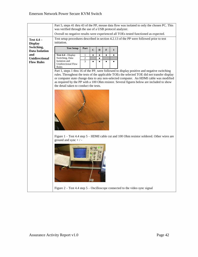
Part 1, steps 1 thru 16 of the PP, were followed to display positive and negative switching
rules. Throughout the tests of the applicable TOEs the selected TOE did not transfer display
or computer state change data to any non-selected computer. An HDMI cable was modified
as required by the PP with a 100 Ohm resistor. Several figures below are included to show
the detail taken to conduct the tests.
Figure 1 – Test 4.4 step 5 – HDMI cable cut and 100 Ohm resistor soldered. Other wires are
ground and sync + / -
Figure 2 – Test 4.4 step 5 – Oscilloscope connected to the video sync signal
Emerson Network Power Secure KVM Switch
Assurance Activity Report v1.0 Page 43
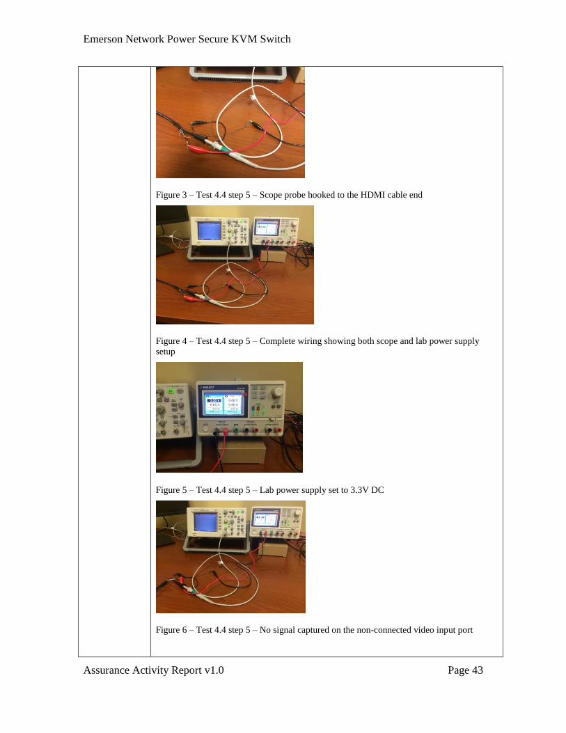
Figure 3 – Test 4.4 step 5 – Scope probe hooked to the HDMI cable end
Figure 4 – Test 4.4 step 5 – Complete wiring showing both scope and lab power supply
setup
Figure 5 – Test 4.4 step 5 – Lab power supply set to 3.3V DC
Figure 6 – Test 4.4 step 5 – No signal captured on the non-connected video input port
Emerson Network Power Secure KVM Switch
Assurance Activity Report v1.0 Page 44
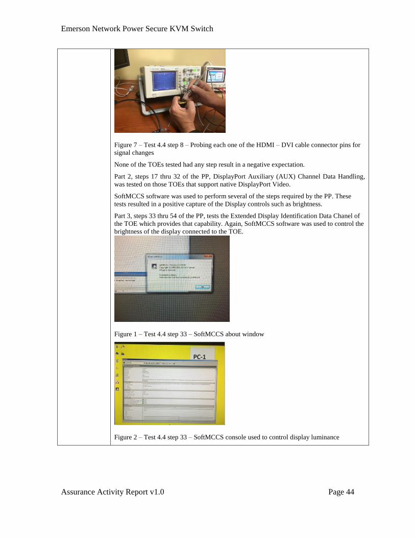
Figure 7 – Test 4.4 step 8 – Probing each one of the HDMI – DVI cable connector pins for
signal changes
None of the TOEs tested had any step result in a negative expectation.
Part 2, steps 17 thru 32 of the PP, DisplayPort Auxiliary (AUX) Channel Data Handling,
was tested on those TOEs that support native DisplayPort Video.
SoftMCCS software was used to perform several of the steps required by the PP. These
tests resulted in a positive capture of the Display controls such as brightness.
Part 3, steps 33 thru 54 of the PP, tests the Extended Display Identification Data Chanel of
the TOE which provides that capability. Again, SoftMCCS software was used to control the
brightness of the display connected to the TOE.
Figure 1 – Test 4.4 step 33 – SoftMCCS about window
Figure 2 – Test 4.4 step 33 – SoftMCCS console used to control display luminance
Emerson Network Power Secure KVM Switch
Assurance Activity Report v1.0 Page 45
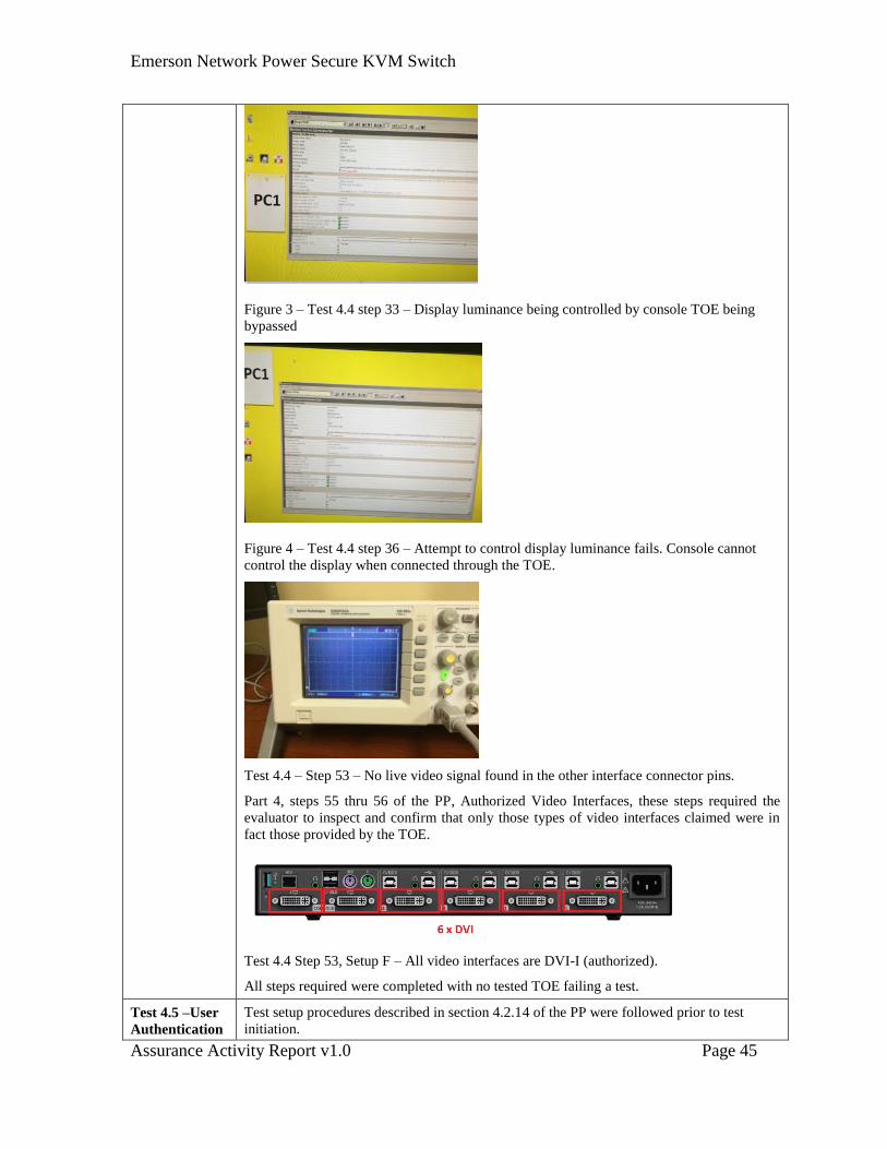
Figure 3 – Test 4.4 step 33 – Display luminance being controlled by console TOE being
bypassed
Figure 4 – Test 4.4 step 36 – Attempt to control display luminance fails. Console cannot
control the display when connected through the TOE.
Test 4.4 – Step 53 – No live video signal found in the other interface connector pins.
Part 4, steps 55 thru 56 of the PP, Authorized Video Interfaces, these steps required the
evaluator to inspect and confirm that only those types of video interfaces claimed were in
fact those provided by the TOE.
Test 4.4 Step 53, Setup F – All video interfaces are DVI-I (authorized).
All steps required were completed with no tested TOE failing a test.
Test 4.5 –User
Authentication
Test setup procedures described in section 4.2.14 of the PP were followed prior to test
initiation.
Emerson Network Power Secure KVM Switch
Assurance Activity Report v1.0 Page 46
Device
Switching and
Isolation Rules
Test Setup Part C D F I
Test 4.5 – User Authentication Device Switching and Isolation Rules
1 ● ● ●
2
3 ● ● ●
4 ● ● ●
5 ● ● ●
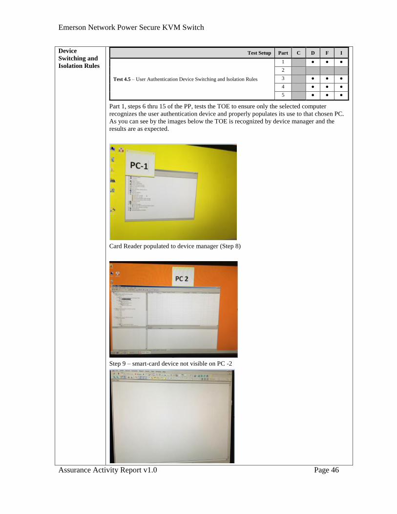
Part 1, steps 6 thru 15 of the PP, tests the TOE to ensure only the selected computer
recognizes the user authentication device and properly populates its use to that chosen PC.
As you can see by the images below the TOE is recognized by device manager and the
results are as expected.
Card Reader populated to device manager (Step 8)
Step 9 – smart-card device not visible on PC -2
Emerson Network Power Secure KVM Switch
Assurance Activity Report v1.0 Page 47
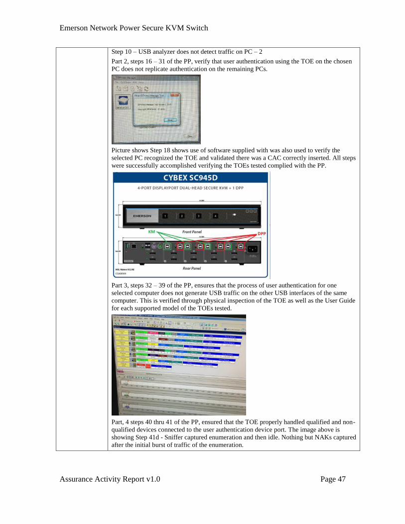
Step 10 – USB analyzer does not detect traffic on PC – 2
Part 2, steps 16 – 31 of the PP, verify that user authentication using the TOE on the chosen
PC does not replicate authentication on the remaining PCs.
Picture shows Step 18 shows use of software supplied with was also used to verify the
selected PC recognized the TOE and validated there was a CAC correctly inserted. All steps
were successfully accomplished verifying the TOEs tested complied with the PP.
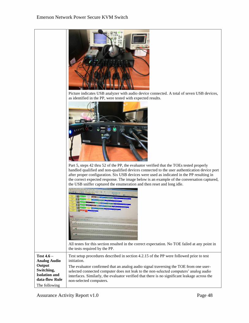
Part 3, steps 32 – 39 of the PP, ensures that the process of user authentication for one
selected computer does not generate USB traffic on the other USB interfaces of the same
computer. This is verified through physical inspection of the TOE as well as the User Guide
for each supported model of the TOEs tested.
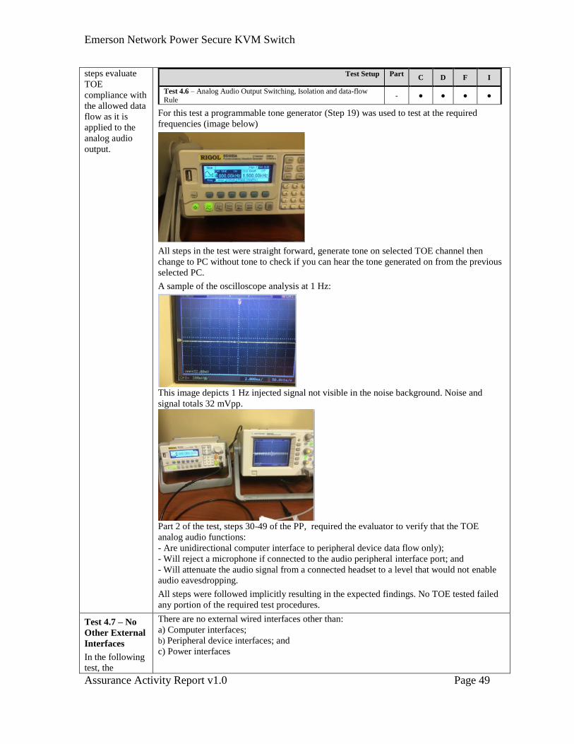
Part, 4 steps 40 thru 41 of the PP, ensured that the TOE properly handled qualified and non-
qualified devices connected to the user authentication device port. The image above is
showing Step 41d - Sniffer captured enumeration and then idle. Nothing but NAKs captured
after the initial burst of traffic of the enumeration.
Emerson Network Power Secure KVM Switch
Assurance Activity Report v1.0 Page 48
Picture indicates USB analyzer with audio device connected. A total of seven USB devices,
as identified in the PP, were tested with expected results.
Part 5, steps 42 thru 52 of the PP, the evaluator verified that the TOEs tested properly
handled qualified and non-qualified devices connected to the user authentication device port
after proper configuration. Six USB devices were used as indicated in the PP resulting in
the correct expected response. The image below is an example of the conversation captured,
the USB sniffer captured the enumeration and then reset and long idle.
All testes for this section resulted in the correct expectation. No TOE failed at any point in
the tests required by the PP.
Test 4.6 –
Analog Audio
Output
Switching,
Isolation and
data-flow Rule
The following
Test setup procedures described in section 4.2.15 of the PP were followed prior to test
initiation.
The evaluator confirmed that an analog audio signal traversing the TOE from one user-
selected connected computer does not leak to the non-selected computers’ analog audio
interfaces. Similarly, the evaluator verified that there is no significant leakage across the
non-selected computers.
Emerson Network Power Secure KVM Switch
Assurance Activity Report v1.0 Page 49
steps evaluate
TOE
compliance with
the allowed data
flow as it is
applied to the
analog audio
output.
Test Setup Part C D F I
Test 4.6 – Analog Audio Output Switching, Isolation and data-flow
Rule - ● ● ● ●
For this test a programmable tone generator (Step 19) was used to test at the required
frequencies (image below)
All steps in the test were straight forward, generate tone on selected TOE channel then
change to PC without tone to check if you can hear the tone generated on from the previous
selected PC.
A sample of the oscilloscope analysis at 1 Hz:
This image depicts 1 Hz injected signal not visible in the noise background. Noise and
signal totals 32 mVpp.
Part 2 of the test, steps 30-49 of the PP, required the evaluator to verify that the TOE
analog audio functions:
- Are unidirectional computer interface to peripheral device data flow only);
- Will reject a microphone if connected to the audio peripheral interface port; and
- Will attenuate the audio signal from a connected headset to a level that would not enable
audio eavesdropping.
All steps were followed implicitly resulting in the expected findings. No TOE tested failed
any portion of the required test procedures.
Test 4.7 – No
Other External
Interfaces
In the following
test, the
There are no external wired interfaces other than:
a) Computer interfaces;
b) Peripheral device interfaces; and
c) Power interfaces
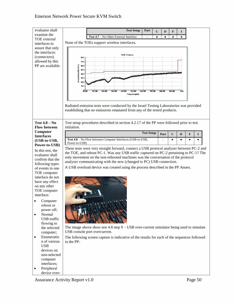
Emerson Network Power Secure KVM Switch
Assurance Activity Report v1.0 Page 50
evaluator shall
examine the
TOE external
interfaces to
assure that only
the interfaces
(connectors)
allowed by this
PP are available.
Test Setup Part C D F I
Test 4.7 – No Other External Interface - ● ● ● ●
None of the TOEs support wireless interfaces.
Radiated emission tests were conducted by the Israel Testing Laboratories was provided
establishing that no emissions emanated from any of the tested products.
Test 4.8 – No
Flow between
Computer
Interfaces
(USB-to-USB,
Power-to-USB)
In this test, the
evaluator shall
confirm that the
following types
of events in one
TOE computer
interface do not
have any effect
on any other
TOE computer
interface:
Computer
reboot or
power off;
Normal
USB traffic
flowing to
the selected
computer;
Enumeratio
n of various
USB
devices on
non-selected
computer
interfaces;
Peripheral
device over-
Test setup procedures described in section 4.2.17 of the PP were followed prior to test
initiation.
Test Setup Part C D F I
Test 4.8 – No Flow between Computer Interfaces (USB-to-USB, Power-to-USB)
- ● ● ● ●
These tests were very straight forward, connect a USB protocol analyzer between PC-2 and
the TOE, and reboot PC-1. Was any USB traffic captured on PC-2 pertaining to PC-1? The
only movement on the non-rebooted machines was the conversation of the protocol
analyzer communicating with the new (changed to PC) USB connection.
A USB overload device was created using the process described in the PP Annex.
The image above show test 4.8 step 9 – USB over-current simulator being used to simulate
USB console port overcurrent.
The following screen capture is indicative of the results for each of the sequences followed
in the PP:
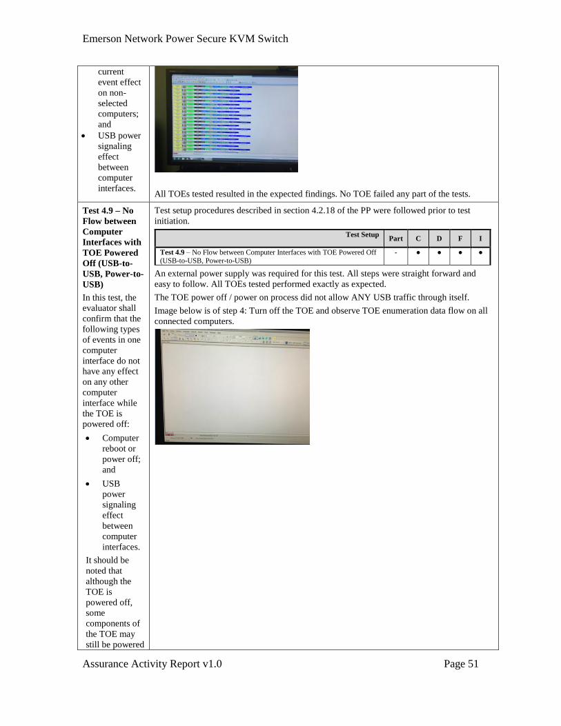
Emerson Network Power Secure KVM Switch
Assurance Activity Report v1.0 Page 51
current
event effect
on non-
selected
computers;
and
USB power
signaling
effect
between
computer
interfaces.
All TOEs tested resulted in the expected findings. No TOE failed any part of the tests.
Test 4.9 – No
Flow between
Computer
Interfaces with
TOE Powered
Off (USB-to-
USB, Power-to-
USB)
In this test, the
evaluator shall
confirm that the
following types
of events in one
computer
interface do not
have any effect
on any other
computer
interface while
the TOE is
powered off:
Computer
reboot or
power off;
and
USB
power
signaling
effect
between
computer
interfaces.
It should be
noted that
although the
TOE is
powered off,
some
components of
the TOE may
still be powered
Test setup procedures described in section 4.2.18 of the PP were followed prior to test
initiation.
Test Setup Part C D F I
Test 4.9 – No Flow between Computer Interfaces with TOE Powered Off (USB-to-USB, Power-to-USB)
- ● ● ● ●
An external power supply was required for this test. All steps were straight forward and
easy to follow. All TOEs tested performed exactly as expected.
The TOE power off / power on process did not allow ANY USB traffic through itself.
Image below is of step 4: Turn off the TOE and observe TOE enumeration data flow on all
connected computers.
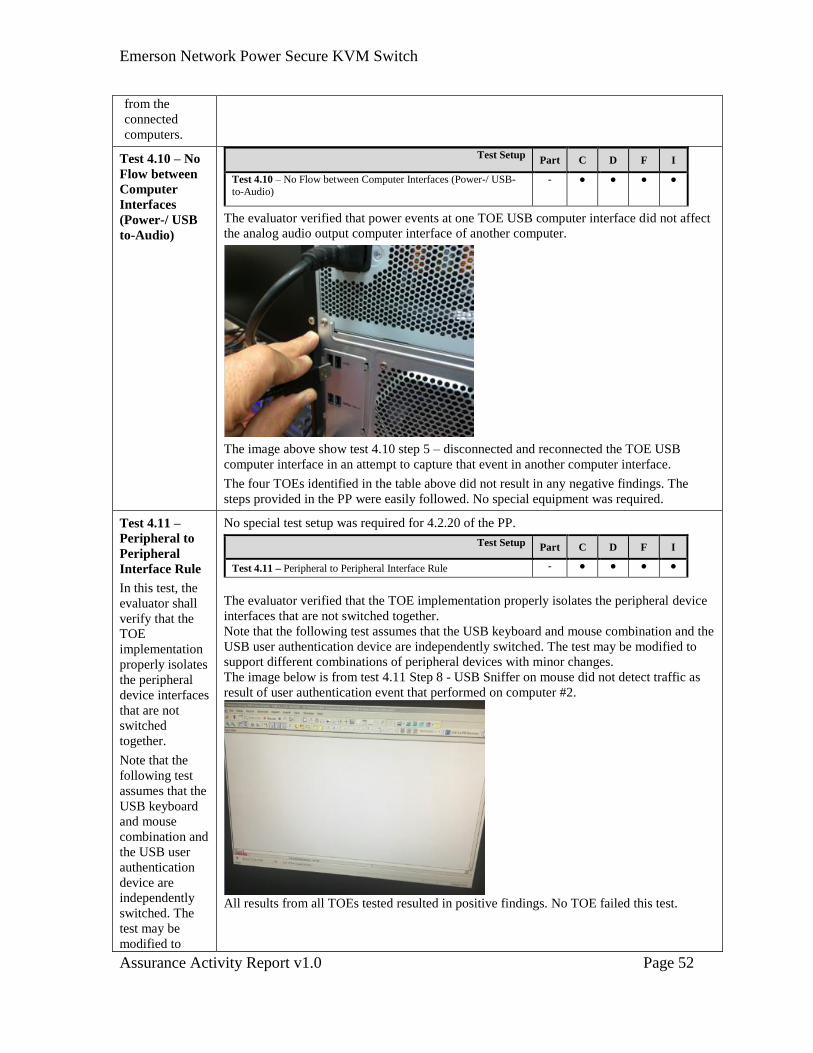
Emerson Network Power Secure KVM Switch
Assurance Activity Report v1.0 Page 52
from the
connected
computers.
Test 4.10 – No
Flow between
Computer
Interfaces
(Power-/ USB
to-Audio)
Test Setup Part C D F I
Test 4.10 – No Flow between Computer Interfaces (Power-/ USB-
to-Audio)
- ● ● ● ●
The evaluator verified that power events at one TOE USB computer interface did not affect
the analog audio output computer interface of another computer.
The image above show test 4.10 step 5 – disconnected and reconnected the TOE USB
computer interface in an attempt to capture that event in another computer interface.
The four TOEs identified in the table above did not result in any negative findings. The
steps provided in the PP were easily followed. No special equipment was required.
Test 4.11 –
Peripheral to
Peripheral
Interface Rule
In this test, the
evaluator shall
verify that the
TOE
implementation
properly isolates
the peripheral
device interfaces
that are not
switched
together.
Note that the
following test
assumes that the
USB keyboard
and mouse
combination and
the USB user
authentication
device are
independently
switched. The
test may be
modified to
No special test setup was required for 4.2.20 of the PP.
Test Setup Part C D F I
Test 4.11 – Peripheral to Peripheral Interface Rule - ● ● ● ●
The evaluator verified that the TOE implementation properly isolates the peripheral device
interfaces that are not switched together.
Note that the following test assumes that the USB keyboard and mouse combination and the
USB user authentication device are independently switched. The test may be modified to
support different combinations of peripheral devices with minor changes.
The image below is from test 4.11 Step 8 - USB Sniffer on mouse did not detect traffic as
result of user authentication event that performed on computer #2.
All results from all TOEs tested resulted in positive findings. No TOE failed this test.
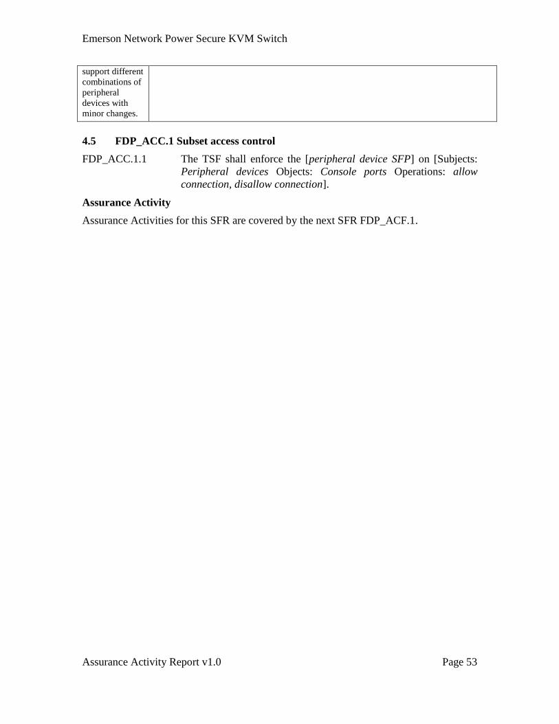
Emerson Network Power Secure KVM Switch
Assurance Activity Report v1.0 Page 53
support different
combinations of
peripheral
devices with
minor changes.
4.5 FDP_ACC.1 Subset access control
FDP_ACC.1.1 The TSF shall enforce the [peripheral device SFP] on [Subjects:
Peripheral devices Objects: Console ports Operations: allow
connection, disallow connection].
Assurance Activity
Assurance Activities for this SFR are covered by the next SFR FDP_ACF.1.
Emerson Network Power Secure KVM Switch
Assurance Activity Report v1.0 Page 54
4.6 FDP_ACF.1 Security attribute based access control
FDP_ACF.1.1 The TSF shall enforce the [peripheral device SFP] to objects based
on the following:
[Subjects: Peripheral devices
Subject security attributes: peripheral device type
Objects: Console ports
Object security attributes: none].
FDP_ACF.1.2 The TSF shall enforce the following rules to determine if an
operation among controlled subjects and controlled objects is
allowed: [The TOE shall query the connected peripheral device
upon initial connection or upon TOE power up and allow
connection for authorized peripheral devices in accordance with
the table in Annex C of this PP].
FDP_ACF.1.3 The TSF shall explicitly authorize access of subjects to objects
based on the following additional rules: [none.].
FDP_ACF.1.4 The TSF shall explicitly deny access of subjects to objects based
on the following additional rules:
[The TOE peripheral device interface (console) port shall reject
any peripheral device with unauthorized values].
TOE Console
Port
Authorized Devices Authorized Protocols
Keyboard Any wired keyboard and keypad
without internal USB hub or
composite device functions;
USB hub and composite devices
are allowed as TOE can filter USB
endpoints (if at least one endpoint
is a keyboard or mouse HID class).
In such case TOE will disable all
other endpoints;
Ps/2 keyboard;
KVM extender;
PS/2 to USB adapter; and
Barcode reader.
USB
Mouse /
Pointing device Any wired mouse or trackball
without internal USB hub or
composite device functions.
USB hub and composite devices
are allowed as TOE can filter USB
endpoints (if at least one endpoint
is a keyboard or mouse HID class).
USB
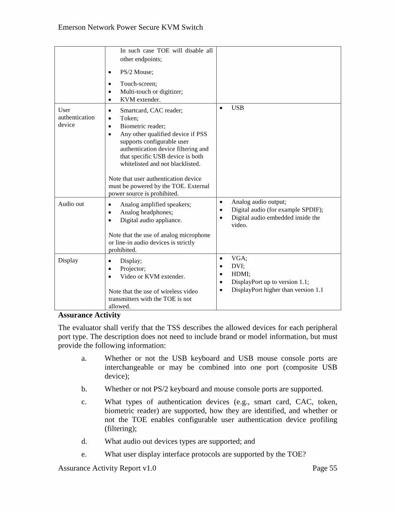
Emerson Network Power Secure KVM Switch
Assurance Activity Report v1.0 Page 55
In such case TOE will disable all
other endpoints;
PS/2 Mouse;
Touch-screen;
Multi-touch or digitizer;
KVM extender.
User
authentication
device
Smartcard, CAC reader;
Token;
Biometric reader;
Any other qualified device if PSS
supports configurable user
authentication device filtering and
that specific USB device is both
whitelisted and not blacklisted.
Note that user authentication device
must be powered by the TOE. External
power source is prohibited.
USB
Audio out Analog amplified speakers;
Analog headphones;
Digital audio appliance.
Note that the use of analog microphone
or line-in audio devices is strictly
prohibited.
Analog audio output;
Digital audio (for example SPDIF);
Digital audio embedded inside the
video.
Display Display;
Projector;
Video or KVM extender.
Note that the use of wireless video
transmitters with the TOE is not
allowed.
VGA;
DVI;
HDMI;
DisplayPort up to version 1.1;
DisplayPort higher than version 1.1
Assurance Activity
The evaluator shall verify that the TSS describes the allowed devices for each peripheral
port type. The description does not need to include brand or model information, but must
provide the following information:
a. Whether or not the USB keyboard and USB mouse console ports are
interchangeable or may be combined into one port (composite USB
device);
b. Whether or not PS/2 keyboard and mouse console ports are supported.
c. What types of authentication devices (e.g., smart card, CAC, token,
biometric reader) are supported, how they are identified, and whether or
not the TOE enables configurable user authentication device profiling
(filtering);
d. What audio out devices types are supported; and
e. What user display interface protocols are supported by the TOE?
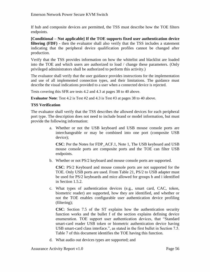
Emerson Network Power Secure KVM Switch
Assurance Activity Report v1.0 Page 56
If hub and composite devices are permitted, the TSS must describe how the TOE filters
endpoints.
[Conditional – Not applicable] If the TOE supports fixed user authentication device
filtering (FDF) - then the evaluator shall also verify that the TSS includes a statement
indicating that the peripheral device qualification profiles cannot be changed after
production.
Verify that the TSS provides information on how the whitelist and blacklist are loaded
into the TOE and which users are authorized to load / change these parameters. (Only
privileged administrators shall be authorized to perform this activity.)
The evaluator shall verify that the user guidance provides instructions for the implementation
and use of all implemented connection types, and their limitations. The guidance must
describe the visual indications provided to a user when a connected device is rejected.
Tests covering this SFR are tests 4.2 and 4.3 at pages 38 to 40 above.
Evaluator Note: Test 4.2 is Test #2 and 4.3 is Test #3 at pages 38 to 40 above.
TSS Verification
The evaluator shall verify that the TSS describes the allowed devices for each peripheral
port type. The description does not need to include brand or model information, but must
provide the following information:
a. Whether or not the USB keyboard and USB mouse console ports are
interchangeable or may be combined into one port (composite USB
device);
CSC: Per the Notes for FDP_ACF.1, Note 1, The USB keyboard and USB
mouse console ports are composite ports and the TOE can filter USB
endpoints.
b. Whether or not PS/2 keyboard and mouse console ports are supported.
CSC: PS/2 Keyboard and mouse console ports are not supported for the
TOE. Only USB ports are used. From Table 21, PS/2 to USB adapter must
be used for PS/2 keyboards and mice allowed for groups h and i identified
in Section 1.5.2.
c. What types of authentication devices (e.g., smart card, CAC, token,
biometric reader) are supported, how they are identified, and whether or
not the TOE enables configurable user authentication device profiling
(filtering);
CSC: Section 7.5 of the ST explains how the authentication security
function works and the bullet f of the section explains defining device
enumeration. TOE support user authentication devices, that “Standard
smart-card reader USB token or biometric authentication device having
USB smart-card class interface.”, as stated in the first bullet in Section 7.5.
Table 7 of this document identifies the TOE having this function.
d. What audio out devices types are supported; and
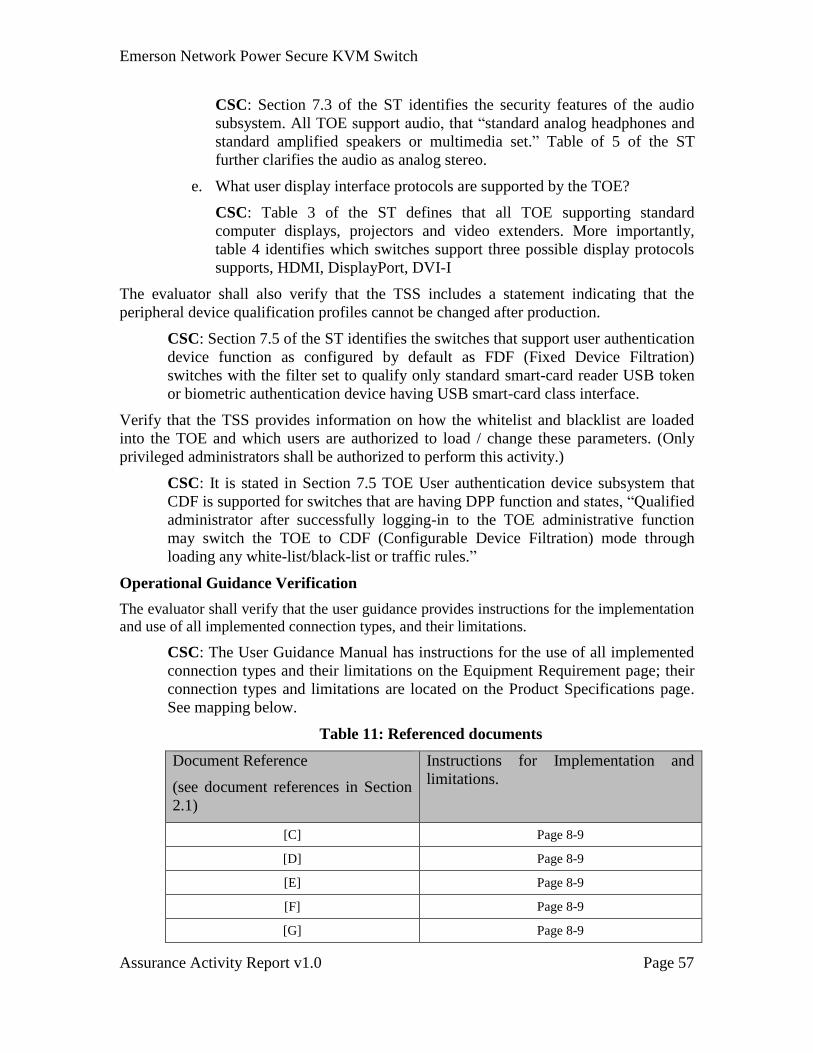
Emerson Network Power Secure KVM Switch
Assurance Activity Report v1.0 Page 57
CSC: Section 7.3 of the ST identifies the security features of the audio
subsystem. All TOE support audio, that “standard analog headphones and
standard amplified speakers or multimedia set.” Table of 5 of the ST
further clarifies the audio as analog stereo.
e. What user display interface protocols are supported by the TOE?
CSC: Table 3 of the ST defines that all TOE supporting standard
computer displays, projectors and video extenders. More importantly,
table 4 identifies which switches support three possible display protocols
supports, HDMI, DisplayPort, DVI-I
The evaluator shall also verify that the TSS includes a statement indicating that the
peripheral device qualification profiles cannot be changed after production.
CSC: Section 7.5 of the ST identifies the switches that support user authentication
device function as configured by default as FDF (Fixed Device Filtration)
switches with the filter set to qualify only standard smart-card reader USB token
or biometric authentication device having USB smart-card class interface.
Verify that the TSS provides information on how the whitelist and blacklist are loaded
into the TOE and which users are authorized to load / change these parameters. (Only
privileged administrators shall be authorized to perform this activity.)
CSC: It is stated in Section 7.5 TOE User authentication device subsystem that
CDF is supported for switches that are having DPP function and states, “Qualified
administrator after successfully logging-in to the TOE administrative function
may switch the TOE to CDF (Configurable Device Filtration) mode through
loading any white-list/black-list or traffic rules.”
Operational Guidance Verification
The evaluator shall verify that the user guidance provides instructions for the implementation
and use of all implemented connection types, and their limitations.
CSC: The User Guidance Manual has instructions for the use of all implemented
connection types and their limitations on the Equipment Requirement page; their
connection types and limitations are located on the Product Specifications page.
See mapping below.
Table 11: Referenced documents
Document Reference
(see document references in Section
2.1)
Instructions for Implementation and
limitations.
[C] Page 8-9
[D] Page 8-9
[E] Page 8-9
[F] Page 8-9
[G] Page 8-9
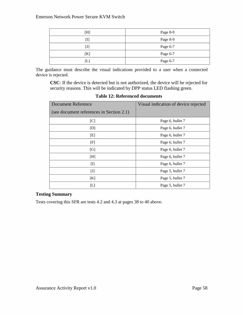
Emerson Network Power Secure KVM Switch
Assurance Activity Report v1.0 Page 58
[H] Page 8-9
[I] Page 8-9
[J] Page 6-7
[K] Page 6-7
[L] Page 6-7
The guidance must describe the visual indications provided to a user when a connected
device is rejected.
CSC: If the device is detected but is not authorized, the device will be rejected for
security reasons. This will be indicated by DPP status LED flashing green.
Table 12: Referenced documents
Document Reference
(see document references in Section 2.1)
Visual indication of device rejected
[C] Page 6, bullet 7
[D] Page 6, bullet 7
[E] Page 6, bullet 7
[F] Page 6, bullet 7
[G] Page 6, bullet 7
[H] Page 6, bullet 7
[I] Page 6, bullet 7
[J] Page 5, bullet 7
[K] Page 5, bullet 7
[L] Page 5, bullet 7
Testing Summary
Tests covering this SFR are tests 4.2 and 4.3 at pages 38 to 40 above.
Emerson Network Power Secure KVM Switch
Assurance Activity Report v1.0 Page 59
4.7 FDP_RIP.1 Subset Residual information protection
FDP_RIP.1.1 [Refinement] the TSF shall ensure that any previous information
content of a resource is made unavailable upon the [deallocation of
the resource from] the following objects: [a TOE computer
interface]:
• Immediately after TOE switch to another selected computer;
• and on start-up of the TOE]
Assurance Activity
TSS
The TSS shall include a detailed Letter of Volatility. The evaluator shall verify that the
TSS Letter of Volatility provides at least the following information:
a. It indicates which TOE components have a non-volatile memory, the non-
volatile memory technology, manufacturer and part number and memory
size.
b. The type of data that the TOE may store on each one of these components.
c. Whether or not each one of these parts is used to store user data and how
this data may remain in the TOE after power down.
d. If the specific component may be independently powered by something
other than the TOE (for example – by a connected computer).
The TSS must indicate whether or not the TOE has user data buffers and how these
buffers are deleted when the user switches to another computer.
Note that user configuration and TOE settings are not user data and therefore may be
stored in the TOE on non-volatile memory components.
Guidance
Check the user or administrative guidance for any limitations regarding transfer of the
TOE between different security levels / roles in the organization. Ensure this guidance is
consistent with the claims in the Security Target.
Check that the user guidance provides a method to purge TOE memory or to Restore
Factory Default settings.
Test
Test 4.12 Residual Information Protection
Evaluator Note: See actual test below
TSS Verification
The TSS shall include a detailed Letter of Volatility. The evaluator shall verify that the
TSS Letter of Volatility provides at least the following information:
Emerson Network Power Secure KVM Switch
Assurance Activity Report v1.0 Page 60
a. It indicates which TOE components have a non-volatile memory, the non-
volatile memory technology, manufacturer and part number and memory
size.
b. The type of data that the TOE may store on each one of these components.
c. Whether or not each one of these parts is used to store user data and how
this data may remain in the TOE after power down.
d. If the specific component may be independently powered by something
other than the TOE (for example – by a connected computer).
CSC: It is stated in the Letter of Volatility through a table which components
have non-volatile memory, the memory technology, manufacturer/part
number/memory size and the types of data the TOE may store on each
component. The text below this table further explains how data is stored and if the
component may be independently powered. The Letter of Volatility is provided in
Annex C of the Security Target.
The TSS must indicate whether or not the TOE has user data buffers and how these
buffers are deleted when the user switches to another computer.
Note that user configuration and TOE settings are not user data and therefore may be
stored in the TOE on non-volatile memory components.
CSC: Section 7.1, bullet l, indicates that during TOE switching from one
computer to another, the system controller function assures that the keyboard and
mouse stacks are deleted and that the first 100 milliseconds of commands
received from the keyboard after switching are ignored (deleted).
Operational Guidance Verification
Check the user or administrative guidance for any limitations regarding transfer of the
TOE between different security levels / roles in the organization. Ensure this guidance is
consistent with the claims in the Security Target.
CSC: Guidance does not provide specific limitations regarding transfer of the
TOE between different security levels/roles in the organization.
Check that the user guidance provides a method to purge TOE memory or to Restore
Factory Default settings.
CSC: All user Guidance describe a ‘Restore-to-Default’ function, it describes
“product boots after Restore-to-Default, the active channel will be #1 and settings
will be reset to default erasing all user-set definitions.” There is also picture
evidence indicating where the ‘Restore-to-Default’ function is on each device.
Table 13: Referenced documents
Document Reference
(see document references in Section 2.1)
[C] Page 6 bullet 2; page 16
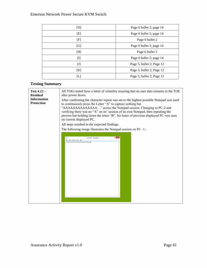
Emerson Network Power Secure KVM Switch
Assurance Activity Report v1.0 Page 61
[D] Page 6 bullet 2; page 14
[E] Page 6 bullet 2; page 14
[F] Page 6 bullet 2
[G] Page 6 bullet 2; page 14
[H] Page 6 bullet 2
[I] Page 6 bullet 2; page 14
[J] Page 5, bullet 2; Page 12
[K] Page 5, bullet 2; Page 12
[L] Page 5, bullet 2; Page 12
Testing Summary
Test 4.12 –
Residual
Information
Protection
All TOEs tested have a letter of volatility assuring that no user data remains in the TOE
after power down.
After confirming the character repeat was set to the highest possible Notepad was used
to continuously press the Letter “A” to capture nothing but
“AAAAAAAAAAAAAA…” across the Notepad session. Changing to PC-2 and
verifying there was no “A” on its’ session of its own Notepad, then repeating the
process but holding down the letter “B”. No letter of previous displayed PC was seen
on current displayed PC.
All steps resulted in the expected findings.
The following image illustrates the Notepad session on PC -1 :
Emerson Network Power Secure KVM Switch
Assurance Activity Report v1.0 Page 62
4.8 FPT_PHP.1 Subset Residual information protection
FPT_PHP.1.1 The TSF shall provide unambiguous detection of physical
tampering that might compromise the TSF.
FPT_PHP.1.2 The TSF shall provide the capability to determine whether physical
tampering with the TSF's devices or TSF's elements has occurred.
Assurance Activity
TSS
The evaluator shall verify that the TSS indicates that the TOE provides unambiguous
detection of physical tampering. The evaluator shall verify that the TSS provides
information that describes how the TOE indicates that it has been tampered with and how
these indications cannot be turned on by the TOE user.
Guidance
The evaluator shall verify that the user guidance describes the mechanism by which the
TOE provides unambiguous detection of physical tampering and provides the user with
instructions for verifying that the TOE has not been tampered with.
Test
The test for this SFR combined with the ant-tampering function testing. See test 4.13 (Test
#13) below.
TSS Verification
The evaluator shall verify that the TSS indicates that the TOE provides unambiguous
detection of physical tampering.
CSC: Section 7.7 of the ST indicates two non-ambiguous physical detection
mechanisms the switches use to detect evidence of tampering.
a) The switches use ‘Tampering Evident Labels’ (TEL) located in on the
TOE enclosure. Any attempt to access the TOE internal circuitry would
cause permanent visible damage to one or more TEL. Each label is
numbered with unique number that recoded by the manufacturer during
TOE production.
b) There is an always-on anti-tampering system mechanically coupled to the
TOE enclosure to detect and attempt to access the TOE internal circuitry.
Once triggered by physically attempting to open the enclosure or
depleting/failing the battery causes the anti-tampering function to trigger
and the TOE will become permanently disabled. The TOE cannot be
recovered.
The evaluator shall verify that the TSS provides information that describes how the TOE
indicates that it has been tampered with and how these indications cannot be turned on by
the TOE user.
Emerson Network Power Secure KVM Switch
Assurance Activity Report v1.0 Page 63
CSC: Section 7.7 indicates, “All TOE interfaces and user functions are disabled
and proper user indications are shown through sequentially blinking front panel
LEDs.” when the TOE has been tampered with.
Operational Guidance Verification
The evaluator shall verify that the user guidance describes the mechanism by which the
TOE provides unambiguous detection of physical tampering and provides the user with
instructions for verifying that the TOE has not been tampered with.
CSC: All the user manuals provided for the evaluation describe the use of tamper
evident labels and the always-on anti-tampering system. All manuals describe
how user can determine from these mechanisms the switch has been tampered
with. The manuals provide a pictorial description of what an untampered tamper
label will look like. See the table below for where each is described in the
manuals. The manuals state the indication for a tampered state as all LEDs
blinking.
Table 14: Referenced documents
Document Reference
(see document references
in Section 2.1)
Tamper evident labels Determining tamper
evident labels have been
tampered with
[C] Page 10 Page 10
[D] Page 10 Page 10
[E] Page 10 Page 10
[F] Page 11 Page 11
[G] Page 10 Page 10
[H] Page 11 Page 11
[I] Page 10 Page 10
[J] Page 8 Page 8
[K] Page 8 Page 8
[L] Page 8 Page 8
Testing Summary
CSC: Test Combined with FPT_PHP.3 as per the Assurance Activity.

Emerson Network Power Secure KVM Switch
Assurance Activity Report v1.0 Page 64
4.9 FPT_PHP.3 Subset Residual information protection
FPT_PHP.3.1 [Refinement] The TSF shall resist [a physical attack on the TOE
for the purpose of gaining access to the internal components, or to
damage the anti-tampering battery] to the [TOE Enclosure] by
responding automatically such that the SFRs are always enforced
becoming permanently disabled.
Assurance Activity
TSS
The evaluator shall verify that the TSS describes the TOE’s reaction to opening the
device enclosure, or damaging/exhausting the anti-tampering battery associated with the
enclosure.
Guidance
The evaluator shall verify that the user guidance warns the user of the actions that will
cause the anti-tampering functionality to disable the device.
Guidance shall also include a clear description of the anti-tampering triggering user
indications.
Test
Test 4.13 Tampered TOE is permanently disabled and properly isolated
Evaluator Note: See actual test below
TSS Verification
The evaluator shall verify that the TSS describes the TOE’s reaction to opening the
device enclosure, or damaging/exhausting the anti-tampering battery associated with the
enclosure.
CSC: Section 7.7 indicates there is an always-on anti-tampering system
mechanically coupled to the TOE enclosure to detect and attempt to access the
TOE internal circuitry. Once triggered by physically attempting to open the
enclosure or depleting/failing the battery causes the anti-tampering function to
trigger and the TOE will become permanently disabled. The TOE cannot be
recovered.
Operational Guidance Verification
The evaluator shall verify that the user guidance warns the user of the actions that will
cause the anti-tampering functionality to disable the device.
CSC: All user manuals provide a clear warning that states, “Important: This
product is equipped with always-on active anti-tampering system. Any attempt to
open the product enclosure will activate the anti-tamper triggers and render the
unit inoperable and warranty void.” See the table below for page reference for the
warning.
Emerson Network Power Secure KVM Switch
Assurance Activity Report v1.0 Page 65
Table 15: Referenced documents
Document Reference
(see document references in
Section 2.1)
Tamper evident label
warning
Determining
tampering system
active
[C] Page 10 Page 10
[D] Page 10 Page 10
[E] Page 10 Page 10
[F] Page 11 Page 11
[G] Page 10 Page 10
[H] Page 11 Page 11
[I] Page 10 Page 10
[J] Page 8 Page 8
[K] Page 8 Page 8
[L] Page 8 Page 8
Guidance shall also include a clear description of the anti-tampering triggering user
indications.
CSC: As stated in FPT_PHP.1, the indication for a tampered state as all LEDs
blinking.
Table 16: Referenced documents
Document Reference
(see document references in Section 2.1)
Determining tampering system active
[C] Page 10
[D] Page 10
[E] Page 10
[F] Page 11
[G] Page 10
[H] Page 11
[I] Page 10
[J] Page 8
[K] Page 8
[L] Page 8
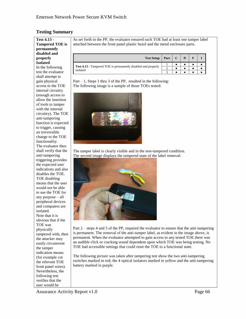
Emerson Network Power Secure KVM Switch
Assurance Activity Report v1.0 Page 66
Testing Summary
Test 4.13 -
Tampered TOE is
permanently
disabled and
properly
Isolated
In the following
test the evaluator
shall attempt to
gain physical
access to the TOE
internal circuitry
(enough access to
allow the insertion
of tools to tamper
with the internal
circuitry). The TOE
anti-tampering
function is expected
to trigger, causing
an irreversible
change to the TOE
functionality.
The evaluator then
shall verify that the
anti-tampering
triggering provides
the expected user
indications and also
disables the TOE.
TOE disabling
means that the user
would not be able
to use the TOE for
any purpose – all
peripheral devices
and computers are
isolated.
Note that it is
obvious that if the
TOE was
physically
tampered with, then
the attacker may
easily circumvent
the tamper
indication means
(for example cut
the relevant TOE
front panel wires).
Nevertheless, the
following test
verifies that the
user would be
As set forth in the PP, the evaluator ensured each TOE had at least one tamper label
attached between the front panel plastic bezel and the metal enclosure parts.
Part – 1, Steps 1 thru 3 of the PP, resulted in the following:
The following image is a sample of those TOEs tested:
The tamper label is clearly visible and in the non-tampered condition.
The second image displays the tampered state of the label removal:
Part 2 – steps 4 and 5 of the PP, required the evaluator to ensure that the anti-tampering
is permanent. The removal of the anti-tamper label, as evident in the image above, is
permanent. When the evaluator attempted to gain access to any tested TOE there was
an audible click or cracking sound dependent upon which TOE was being testing. No
TOE had accessible settings that could reset the TOE to a functional state.
The following picture was taken after tampering test show the two anti-tampering
switches marked in red; the 4 optical isolators marked in yellow and the anti-tampering
battery marked in purple.
Test Setup Part C D F I
Test 4.13 - Tampered TOE is permanently disabled and properly isolated
1 ● ● ● ●
2 ● ● ● ●
3 ● ● ● ●
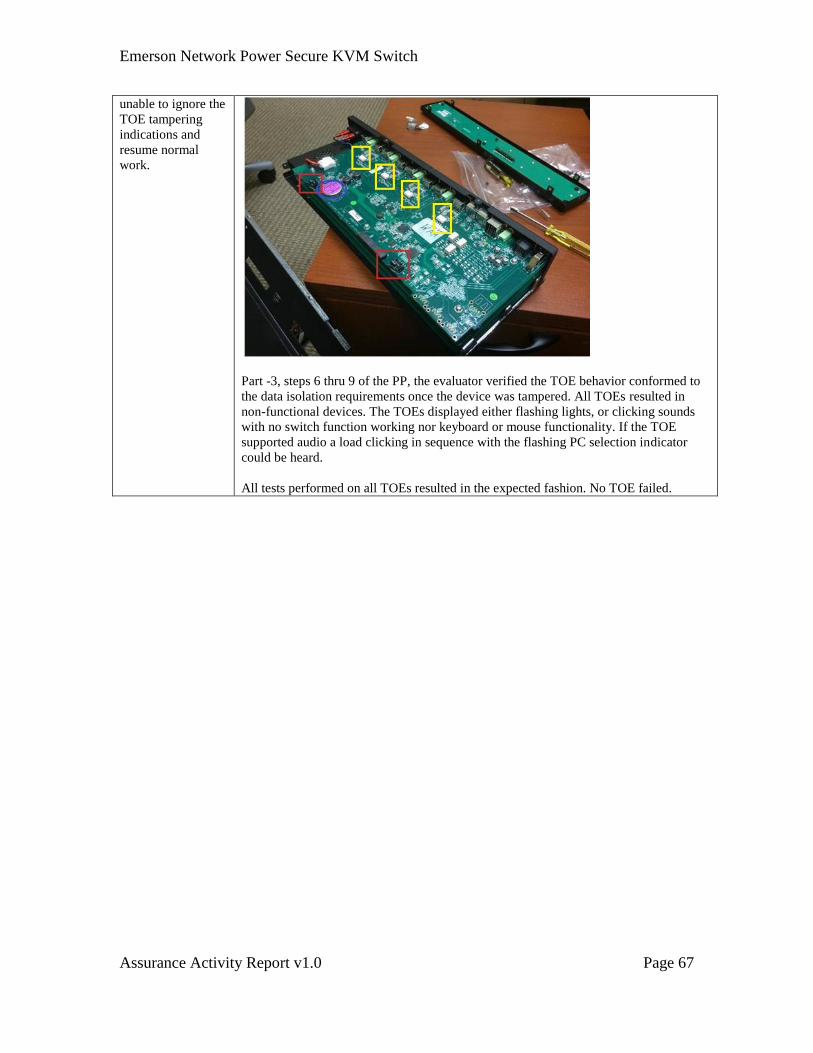
Emerson Network Power Secure KVM Switch
Assurance Activity Report v1.0 Page 67
unable to ignore the
TOE tampering
indications and
resume normal
work.
Part -3, steps 6 thru 9 of the PP, the evaluator verified the TOE behavior conformed to
the data isolation requirements once the device was tampered. All TOEs resulted in
non-functional devices. The TOEs displayed either flashing lights, or clicking sounds
with no switch function working nor keyboard or mouse functionality. If the TOE
supported audio a load clicking in sequence with the flashing PC selection indicator
could be heard.
All tests performed on all TOEs resulted in the expected fashion. No TOE failed.
Emerson Network Power Secure KVM Switch
Assurance Activity Report v1.0 Page 68
4.10 FPT_FLS.1 Failure with preservation of secure state
FPT_FLS.1.1 The TSF shall preserve a secure state by disabling the TOE when
the following types of failures occur: [failure of the power on self-
test, failure of the anti-tampering function].
Assurance Activity
Assurance Activities for this SFR were integrated with the TSF Testing Assurance
Activities below.
TSS Verification
The evaluator shall verify that the TSS describes the secure state when the failure of the
power on self-test and failure of the anti-tampering function occur.
CSC: It is stated in Section 7.8, TOE Self-testing, that if the self-testing function
has failed, the TOE will provide proper user indications and will disable normal
operation.
In Section 7.7, when the anti-tampering mechanism is triggered, “all TOE
interfaces and user functions are disabled and proper user indications are shown
through sequentially blinking front panel LEDs.” when the TOE has been
tampered with.”
Operational Guidance Verification
The evaluator shall verify that the guidance describes the secure state when the failure of
the power on self-test and failure of the anti-tampering function occur.
CSC: All user guidance state a precaution in case of self-test failure, “As product
powers-up it performs a self-test procedure. In case of self-test failure for any
reason, including jammed buttons, the product will be Inoperable. Self-test failure
will be indicated by the following abnormal LED behavior:
a. All channel-select LEDs will be turned ON and then OFF;
b. A specific, predefined LED combination will be turned ON;
c. The predefined LED combination will indicate the problem type (jammed
buttons, firmware integrity).
Try to power cycle product. If problem persists please contact your system
administrator or technical support.”
Table 17: Referenced documents
Document Reference
(see document references in Section 2.1)
Self-Test and Anti-Tampering
Failure
[C] Page 6, bullet 1 & 6
[D] Page 6, bullet 1 & 6
[E] Page 6, bullet 1 & 6
[F] Page 6, bullet 1 & 6
Emerson Network Power Secure KVM Switch
Assurance Activity Report v1.0 Page 69
[G] Page 6, bullet 1 & 6
[H] Page 6, bullet 1 & 6
[I] Page 6, bullet 1 & 6
[J] Page 5, bullet 1 & 6
[K] Page 5, bullet 1 & 6
[L] Page 5, bullet 1 & 6
Testing Summary
CSC: FPT_PHP.3, Test 4.13, showed the tampered TOE is permanently disabled
and properly isolated.
.
Emerson Network Power Secure KVM Switch
Assurance Activity Report v1.0 Page 70
4.11 FPT_TST.1 TSF testing
FPT_TST.1.1 [Refinement] The TSF shall run a suite of self-tests that includes
as minimum:
a. Test of the basic TOE hardware and firmware integrity; and
b. Test of the basic computer-to-computer isolation; and
c. Test of critical security functions (i.e., user control and anti-
tampering).
[during initial startup, [upon reset button activation]] to
demonstrate the correct operation of [the TSF].
FPT_TST.1.2 The TSF shall provide users with the capability to verify the
integrity of [the TSF functionality].
FPT_TST.1.3 The TSF shall provide users with the capability to verify the
integrity of [the TSF].
Assurance Activity
TSS
The evaluator shall verify that the TSS describes the self- tests that are performed on start
up or on reset (if a reset function is available). The evaluator shall verify that the self-test
covers at least the following:
a) a basic integrity test of the TOE hardware and firmware (for example,
memory testing and firmware checksum compare);
b) a test of the computer interfaces’ isolation functionality (for example,
generating data flow on one port and checking that it is not received on
another port);
c) a test of the user interface – in particular tests of the user control
mechanism (for example checking that the front panel push-buttons are
not jammed); and
d) a test of the anti-tampering mechanism (for example checking that the
backup battery is functional).
The evaluator shall verify that the TSS describes how the TOE ensures a shutdown upon
a self-test failure or a failed anti-tampering function. If there are instances when a
shutdown does not occur (e.g., a failure is deemed non-security relevant), those cases are
identified and a rationale is provided explaining why the TOE’s ability to enforce its
security policies is not affected.
The evaluator shall check the TSS to verify that it describes the TOE behavior in case of self-
test failure. The evaluator shall verify that the described TOE behavior includes shutting
down the PSS functionality once the failure is detected.
Guidance
The evaluator shall verify that the user guidance:
a. describes how the results of self-tests are indicated to the user;
Emerson Network Power Secure KVM Switch
Assurance Activity Report v1.0 Page 71
b. provides the user with a clear indication of how to recognize a failed self-
test; and
c. details the appropriate actions to be completed in response to a failed self-
test.
The evaluator shall verify that the user / administrative guidance provide adequate
information on TOE self-test failures, their causes and their indications.
Test
Test 4.14 Self-Test Pass and Fail
Evaluator Note: See actual test below
TSS Verification
The evaluator shall verify that the TSS describes the self-tests that are performed on start
up or on reset (if a reset function is available).
CSC: Section 7.8 describes power-up self-tests the TOE performs.
The evaluator shall verify that the self-test covers at least the following:
a) a basic integrity test of the TOE hardware and firmware (for example,
memory testing and firmware checksum compare);
b) a test of the computer interfaces’ isolation functionality (for example,
generating data flow on one port and checking that it is not received on
another port);
c) a test of the user interface – in particular tests of the user control
mechanism (for example checking that the front panel push-buttons are
not jammed); and
d) a test of the anti-tampering mechanism (for example checking that the
backup battery is functional).
CSC: It is stated in the ST, Section 7.8 bullet b, the self-testing function checks
the integrity of the TOE microcontrollers firmware, the anti-tampering function,
and the control functions, which satisfies bullets a, c and d above.
It is additionally stated in bullet c of Section 7.8 in the ST the self-test function
tests “computer ports isolation by running test packets at different interfaces and
attempting to detect traffic at all other interfaces.”
The evaluator shall verify that the TSS describes how the TOE ensures a shutdown upon
a self-test failure or a failed anti-tampering function. If there are instances when a
shutdown does not occur (e.g., a failure is deemed non-security relevant), those cases are
identified and a rationale is provided explaining why the TOE’s ability to enforce its
security policies is not affected.
CSC: Section 7.8 (Self Tests) or Section 7.7 (Anti-Tampering) of the ST does not
indicate any situations where the TOE does not become disabled on failure of a
self-test or triggering the anti-tampering function. Both sections indicate how the
TOE responds by sequentially blinking front panel LEDs.
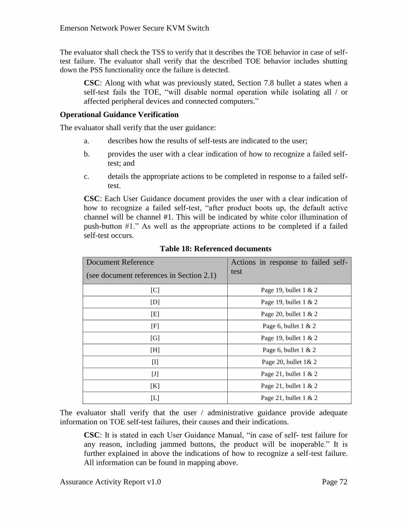
Emerson Network Power Secure KVM Switch
Assurance Activity Report v1.0 Page 72
The evaluator shall check the TSS to verify that it describes the TOE behavior in case of self-
test failure. The evaluator shall verify that the described TOE behavior includes shutting
down the PSS functionality once the failure is detected.
CSC: Along with what was previously stated, Section 7.8 bullet a states when a
self-test fails the TOE, “will disable normal operation while isolating all / or
affected peripheral devices and connected computers.”
Operational Guidance Verification
The evaluator shall verify that the user guidance:
a. describes how the results of self-tests are indicated to the user;
b. provides the user with a clear indication of how to recognize a failed self-
test; and
c. details the appropriate actions to be completed in response to a failed self-
test.
CSC: Each User Guidance document provides the user with a clear indication of
how to recognize a failed self-test, “after product boots up, the default active
channel will be channel #1. This will be indicated by white color illumination of
push-button #1.” As well as the appropriate actions to be completed if a failed
self-test occurs.
Table 18: Referenced documents
Document Reference
(see document references in Section 2.1)
Actions in response to failed self-
test
[C] Page 19, bullet 1 & 2
[D] Page 19, bullet 1 & 2
[E] Page 20, bullet 1 & 2
[F] Page 6, bullet 1 & 2
[G] Page 19, bullet 1 & 2
[H] Page 6, bullet 1 & 2
[I] Page 20, bullet 1& 2
[J] Page 21, bullet 1 & 2
[K] Page 21, bullet 1 & 2
[L] Page 21, bullet 1 & 2
The evaluator shall verify that the user / administrative guidance provide adequate
information on TOE self-test failures, their causes and their indications.
CSC: It is stated in each User Guidance Manual, “in case of self- test failure for
any reason, including jammed buttons, the product will be inoperable.” It is
further explained in above the indications of how to recognize a self-test failure.
All information can be found in mapping above.
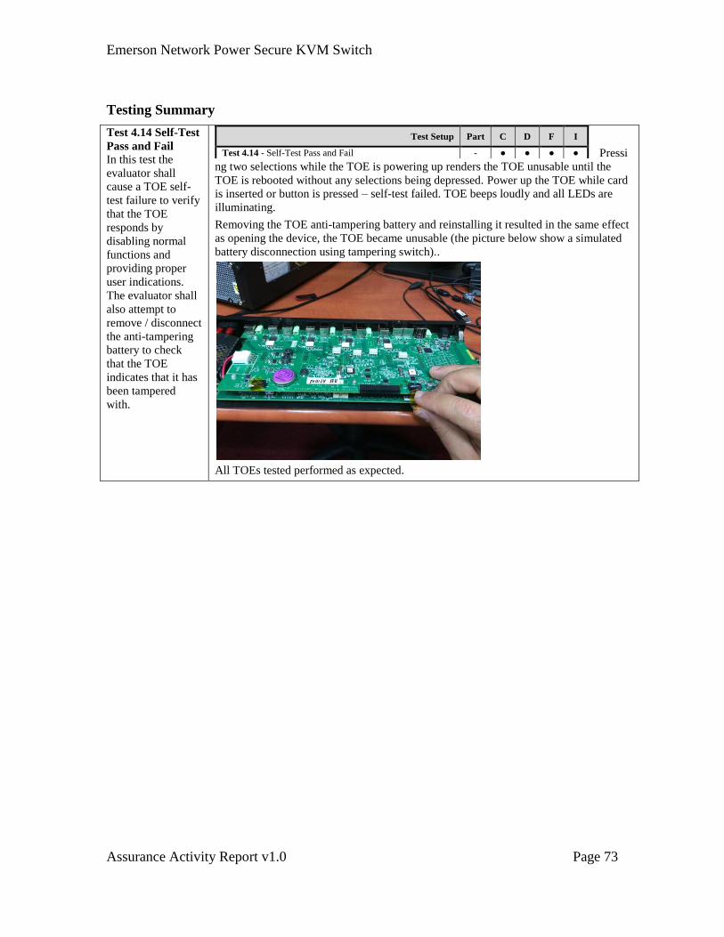
Emerson Network Power Secure KVM Switch
Assurance Activity Report v1.0 Page 73
Testing Summary
Test 4.14 Self-Test
Pass and Fail
In this test the
evaluator shall
cause a TOE self-
test failure to verify
that the TOE
responds by
disabling normal
functions and
providing proper
user indications.
The evaluator shall
also attempt to
remove / disconnect
the anti-tampering
battery to check
that the TOE
indicates that it has
been tampered
with.
Pressi
ng two selections while the TOE is powering up renders the TOE unusable until the
TOE is rebooted without any selections being depressed. Power up the TOE while card
is inserted or button is pressed – self-test failed. TOE beeps loudly and all LEDs are
illuminating.
Removing the TOE anti-tampering battery and reinstalling it resulted in the same effect
as opening the device, the TOE became unusable (the picture below show a simulated
battery disconnection using tampering switch)..
All TOEs tested performed as expected.
Test Setup Part C D F I
Test 4.14 - Self-Test Pass and Fail - ● ● ● ●

Emerson Network Power Secure KVM Switch
Assurance Activity Report v1.0 Page 74
4.12 FTA_CIN_EXT.1 Extended: Continuous Indications
FTA_CIN_EXT.1.1 The TSF shall display a continuous visual indication of the
computer to which the user is currently connected, including on
power up, [on reset].
Assurance Activity
TSS
The evaluator shall verify that the TSS describes how the switch behaves on power up.
The TSS must indicate whether or not the TOE has a reset option and, if so, the TSS shall
describe how the switch behaves when this option is exercised.
Guidance
The evaluator shall verify that the user guidance notes which computer port group will be
connected on TOE power up or recovery from reset, if this is an option. Where a reset
option is available, use of this feature must be described in the user guidance.
Test
Test 4.15 – Power Up Defaults, Continuous Indications and Single Control
Evaluator Note: See actual test below
TSS Verification
The evaluator shall verify that the TSS describes how the switch behaves on power up.
CSC: In Section 7.6, bullets h and i identify the visual indicators during the power
up and self-test sequences during power up. The bullets state, “
h. The communication, configuration and integrity of the TOE front panel are
being tested during power up self-testing. During power up until the TOE
successfully passed the self-test, no channel is selected and therefore no TOE state
provided to the user.
i. After self-test passed at all times that the TOE is operative, front panel
indications are provided and cannot be turned off or dimmed by the user in any
way.”
The TSS must indicate whether or not the TOE has a reset option and, if so, the TSS shall
describe how the switch behaves when this option is exercised.
CSC: Bullet j of Section 7.6 states all switches have a “Restore to Factory
Default recessed switch” and the bullet further explains the behavior of the switch
when the button is pressed during normal operation.
Operational Guidance Verification
The evaluator shall verify that the user guidance notes which computer port group will be
connected on TOE power up or recovery from reset, if this is an option. Where a reset
option is available, use of this feature must be described in the user guidance.
CSC: Each User Manual describes the power up setup, in which it states which
port group will be connected on TOE when powering up, “By default, after
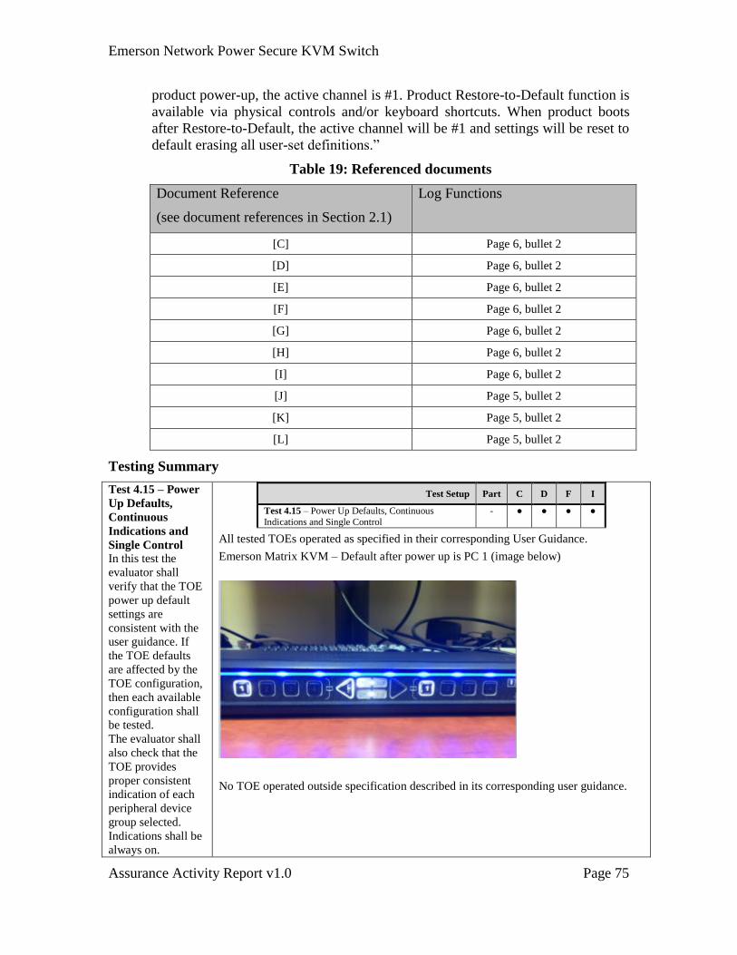
Emerson Network Power Secure KVM Switch
Assurance Activity Report v1.0 Page 75
product power-up, the active channel is #1. Product Restore-to-Default function is
available via physical controls and/or keyboard shortcuts. When product boots
after Restore-to-Default, the active channel will be #1 and settings will be reset to
default erasing all user-set definitions.”
Table 19: Referenced documents
Document Reference
(see document references in Section 2.1)
Log Functions
[C] Page 6, bullet 2
[D] Page 6, bullet 2
[E] Page 6, bullet 2
[F] Page 6, bullet 2
[G] Page 6, bullet 2
[H] Page 6, bullet 2
[I] Page 6, bullet 2
[J] Page 5, bullet 2
[K] Page 5, bullet 2
[L] Page 5, bullet 2
Testing Summary
Test 4.15 – Power
Up Defaults,
Continuous
Indications and
Single Control
In this test the
evaluator shall
verify that the TOE
power up default
settings are
consistent with the
user guidance. If
the TOE defaults
are affected by the
TOE configuration,
then each available
configuration shall
be tested.
The evaluator shall
also check that the
TOE provides
proper consistent
indication of each
peripheral device
group selected.
Indications shall be
always on.
Test Setup Part C D F I
Test 4.15 – Power Up Defaults, Continuous
Indications and Single Control
- ● ● ● ●
All tested TOEs operated as specified in their corresponding User Guidance.
Emerson Matrix KVM – Default after power up is PC 1 (image below)
No TOE operated outside specification described in its corresponding user guidance.
Emerson Network Power Secure KVM Switch
Assurance Activity Report v1.0 Page 76
4.13 FAU_GEN.1: Audit Data Generation
FAU_GEN.1.1 The TSF shall be able to generate an audit record of the following
auditable events:
a) Start-up and shutdown of the audit functions;
b) All auditable events for the [not specified] level of audit; and
c) [administrator login, administrator logout, and [assignment: all
administrative functions claimed in FMT_MOF.1 and
FMT_SMF.1]]
FAU_GEN.1.2 The TSF shall record within each audit record at least the
following information:
a) Date and time of the event, type of event, subject identity (if
applicable), and the outcome (success or failure) of the event; and
b) For each audit event type, based on the auditable event
definitions of the functional components included in the PP/ST,
[no other information].
Assurance Activity
TSS
The evaluator shall verify that the TSS describes the audit functionality including which
events are audited, what information is saved in each record type, how the records are
stored, the conditions in which audit records are overwritten, and the means by which the
audit records may be read. Although the TOE may provide an interface for an
administrator to view the audit records, this is not a requirement.
Test
The evaluator shall perform each of the auditable functions to succeed, and where
possible, to fail. The evaluator shall use the means described in the TSS to access the
audit records and verify that each of the events has been recorded, with all of the
expected information.
TSS Verification
The evaluator shall verify that the TSS describes the audit functionality including which
events are audited, what information is saved in each record type, how the records are
stored, the conditions in which audit records are overwritten, and the means by which the
audit records may be read.
CSC: Section 7.8 of the ST describes what events are audited and their stored
location. There are events stored in a critical log area and non-critical log area.
Critical events include product registration information, anti-tampering arming
event and all tampering events detected (may be more than one, last admin log-on
information and last self-test failure information. The non-critical events are
administrator log in and changes made, changes in administrator password,
rejection of USB devices, self-test failures, CDF (black-list / white-list) and traffic
rules uploading, and power up and down cycles.
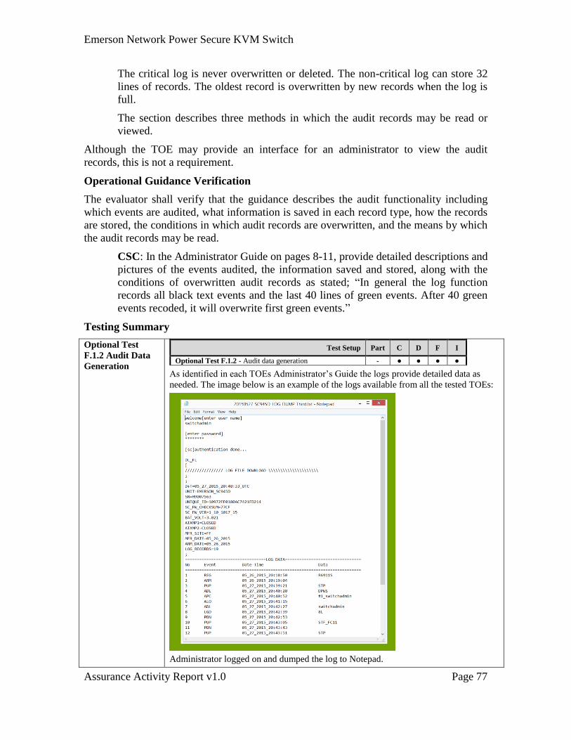
Emerson Network Power Secure KVM Switch
Assurance Activity Report v1.0 Page 77
The critical log is never overwritten or deleted. The non-critical log can store 32
lines of records. The oldest record is overwritten by new records when the log is
full.
The section describes three methods in which the audit records may be read or
viewed.
Although the TOE may provide an interface for an administrator to view the audit
records, this is not a requirement.
Operational Guidance Verification
The evaluator shall verify that the guidance describes the audit functionality including
which events are audited, what information is saved in each record type, how the records
are stored, the conditions in which audit records are overwritten, and the means by which
the audit records may be read.
CSC: In the Administrator Guide on pages 8-11, provide detailed descriptions and
pictures of the events audited, the information saved and stored, along with the
conditions of overwritten audit records as stated; “In general the log function
records all black text events and the last 40 lines of green events. After 40 green
events recoded, it will overwrite first green events.”
Testing Summary
Optional Test
F.1.2 Audit Data
Generation
Test Setup Part C D F I
Optional Test F.1.2 - Audit data generation - ● ● ● ●
As identified in each TOEs Administrator’s Guide the logs provide detailed data as
needed. The image below is an example of the logs available from all the tested TOEs:
Administrator logged on and dumped the log to Notepad.
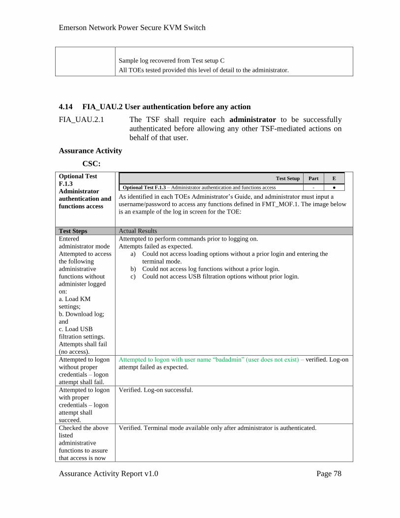
Emerson Network Power Secure KVM Switch
Assurance Activity Report v1.0 Page 78
Sample log recovered from Test setup C
All TOEs tested provided this level of detail to the administrator.
4.14 FIA_UAU.2 User authentication before any action
FIA_UAU.2.1 The TSF shall require each administrator to be successfully
authenticated before allowing any other TSF-mediated actions on
behalf of that user.
Assurance Activity
CSC:
Optional Test
F.1.3
Administrator
authentication and
functions access
Test Setup Part E
Optional Test F.1.3 – Administrator authentication and functions access - ●
As identified in each TOEs Administrator’s Guide, and administrator must input a
username/password to access any functions defined in FMT_MOF.1. The image below
is an example of the log in screen for the TOE:
Test Steps Actual Results
Entered
administrator mode
Attempted to access
the following
administrative
functions without
administer logged
on:
a. Load KM
settings;
b. Download log;
and
c. Load USB
filtration settings.
Attempts shall fail
(no access).
Attempted to perform commands prior to logging on.
Attempts failed as expected.
a) Could not access loading options without a prior login and entering the
terminal mode.
b) Could not access log functions without a prior login.
c) Could not access USB filtration options without prior login.
Attempted to logon
without proper
credentials – logon
attempt shall fail.
Attempted to logon with user name “badadmin” (user does not exist) – verified. Log-on
attempt failed as expected.
Attempted to logon
with proper
credentials – logon
attempt shall
succeed.
Verified. Log-on successful.
Checked the above
listed
administrative
functions to assure
that access is now
Verified. Terminal mode available only after administrator is authenticated.
Emerson Network Power Secure KVM Switch
Assurance Activity Report v1.0 Page 79
possible.
Checked that the
failed and passed
administrator logon
attempts are
properly logged.
Verified. Both events were properly logged with cause, date and time.
4.15 FIA_UID.2 User identification before any action
FIA_UID.2.1 The TSF shall require each administrator to be successfully
identified before allowing any other TSF-mediated actions on
behalf of that user.
Assurance Activity
CSC: Refer to FIA_UAU.2.1. As noted in FMT_MOF.1 below, Optional Test
F.1.3 included identification and authentication when using management
functions.
4.16 FMT_MOF.1 Management of security functions behavior
FMT_MOF.1.1 The TSF will restrict the ability to [perform] the functions [modify
TOE user authentication device filtering (CDF) whitelist and
blacklist] to [the authorized administrators].
Assurance Activity
TSS
The evaluator shall verify that the TSS describes the mechanism for preventing non-
administrators from accessing the administrative functions stated above.
Guidance
The evaluator shall check the user and administrative guidance to verify that the
administrative functions defined above are only available to identified administrators.
Test
The testing for this SFR is covered in Tests 4.5 at page 44 above and Test F1 below.
TSS Verification
The evaluator shall verify that the TSS describes the mechanism for preventing non-
administrators from accessing the administrative functions stated above.
CSC: The notes included in Section 6.1.9 state that logging on with administrator
identification and authentication is required for management functions.
Section 7.5 requires a qualified administrator to successfully log-in to switch the
TOE to CDF mode through loading any white-list/black-list or traffic rules.
Operational Guidance Verification
The evaluator shall check the user and administrative guidance to verify that the
administrative functions defined above are only available to identified administrators.
Emerson Network Power Secure KVM Switch
Assurance Activity Report v1.0 Page 80
CSC: The DPP Configuration Manual describes that “Configurable Device
Filtering (CDF) mechanism is used with configuration permissions limited to
authenticated administrators” on page 9. The Administrator guide describes on
page 8 describes how to authenticate properly to the switch through the
management PC.
Testing Summary
CSC: Refer to Optional Test F.1.3 for test results. The test required
Administrative access to define black-listed and whitelisted devices USB (CDF).
All black-listed USB devices rejected by the TOE as expected. All white-listed
USB devices that were not black-listed as well were accepted by the TOE as
expected.
Emerson Network Power Secure KVM Switch
Assurance Activity Report v1.0 Page 81
4.17 FMT_SMF.1 Management of security functions behavior
FMT_SMF.1.1 The TOE shall be capable of performing the following
management functions:
a. TOE shall provide authorized administrators the option to
assign whitelist and blacklist definitions for the TOE user
authentication device qualification function,
b. [Assignment: and the ability to define specific data flow rules
for specific computer interfaces].
Assurance Activity
TSS
The evaluator shall check to ensure the TSS describes the various administrator and user
TOE configurations and how they are used by the TOE.
Guidance
The evaluator shall check to make sure that every management function mandated in the
ST for this requirement are described in the operational guidance and that the description
contains the information required to perform the management duties associated with each
management function.
Test
The testing for this SFR is covered in:
The testing for this SFR is covered in:
FMT_SMF.1.1 a - Test F1 above.
FMT_SMF.1.1 b - Test 4.5 Part 5 above.
TSS Verification
The evaluator shall check to ensure the TSS describes the various administrator and user
TOE configurations and how they are used by the TOE.
CSC: Section 7.5 of the ST states, “Traffic rules are only related to preventing
DPP from being switched to the currently selected computer. While in this mode,
the TOE may qualify any USB 1.1, 2.0 or 3.0 based on the following one or more
criterions: USB Class, USB Sub-class, USB Protocol, USB device ID, USB
Vendor ID, and USB Serial number.”
Operational Guidance Verification
The evaluator shall check to make sure that every management function mandated in the
ST for this requirement are described in the operational guidance and that the description
contains the information required to perform the management duties associated with each
management function.
CSC: The Configuration Manual for TOE (as defined in table 9 above), Page 18;
describes where you select specific channels for the different USB devices. The
“USB status LED will blink and turn off indicating the new settings are stored.”
Emerson Network Power Secure KVM Switch
Assurance Activity Report v1.0 Page 82
Testing Summary
CSC: Refer to Test 4.5 in page 44 above for test results. The test required
Administrative access to define black-listed and whitelisted devices USB (CDF). All
black-listed USB devices rejected by the TOE as expected. All white-listed USB
devices that were not black-listed as well were accepted by the TOE as expected..
Emerson Network Power Secure KVM Switch
Assurance Activity Report v1.0 Page 83
4.18 FMT_SMR.1 Security roles
FMT_SMR.1.1 The TSF will maintain the roles [users, administrators].
Assurance Activity
Refer to the assurance activities of FMT_MOF.1.1 at page 76 above.
Testing Summary
CSC: Refer to Test 4.5 for test results. The test required Administrative access to
define black-listed and whitelisted devices USB (CDF). All black-listed USB
devices rejected by the TOE as expected. Device LED provided proper indication
for rejection. All white-listed USB devices that were not black-listed as well were
accepted by the TOE as expected.
Emerson Network Power Secure KVM Switch
Assurance Activity Report v1.0 Page 84
4.19 FTA_ATH_EXT.1 User authentication device reset
FTA_ATH_EXT.1.1 The TSF shall reset the power supplied to the user authentication
device for at least one second when the user switches the device
from one computer to another.
Assurance Activity
TSS
The evaluator shall verify that the TSS describes how the TOE resets the power to the
user authentication device. The TSS shall also describe the amount of capacitance in the
TOE and how it will affect the voltage decrease on an average user authentication device.
Capacitance shall be small enough to assure that low-power devices would reach less
than 2.0 V during that one second power reset.
Guidance
The evaluator shall verify that the user guidance provides information about the
prohibited use of user authentication devices with external power sources.
Test
The testing for this SFR is covered in:
FMT_SMF.1.1 b - Test 4.5 Part 1 above.
TSS Verification
The evaluator shall verify that the TSS describes how the TOE resets the power to the
user authentication device.
CSC: Section 7.5, bullet g of the ST describes how the TOE resets power to the
user authentication device when the user switches to a different computer. The
bullet states in part, “Once the user switches the connected computer, the TOE
resets the user authentication device through power supply switching (temporary
power dip as defined by the referenced PP).” The bullet further details the
technical details of the power supply switching.
The TSS shall also describe the amount of capacitance in the TOE and how it will affect
the voltage decrease on an average user authentication device. Capacitance shall be small
enough to assure that low-power devices would reach less than 2.0 V during that one
second power reset.
CSC: Section 7.5, bullet g of the ST describes in the technical details the level of
capacitance and the either the TOE supply or any voltage remaining in the
capacitors is shorted to ground to ensure that less than 2.0V is reached.
Operational Guidance Verification
The evaluator shall verify that the user guidance provides information about the
prohibited use of user authentication devices with external power sources.
CSC: It is stated in the User Guidance Manuals, “do not connect any
authentication device with an external power source to product.”
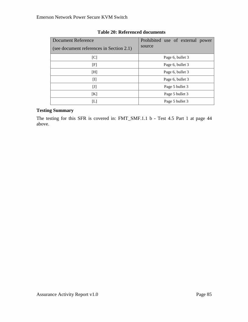
Emerson Network Power Secure KVM Switch
Assurance Activity Report v1.0 Page 85
Table 20: Referenced documents
Document Reference
(see document references in Section 2.1)
Prohibited use of external power
source
[C] Page 6, bullet 3
[F] Page 6, bullet 3
[H] Page 6, bullet 3
[I] Page 6, bullet 3
[J] Page 5 bullet 3
[K] Page 5 bullet 3
[L] Page 5 bullet 3
Testing Summary
The testing for this SFR is covered in: FMT_SMF.1.1 b - Test 4.5 Part 1 at page 44
above.
Emerson Network Power Secure KVM Switch
Assurance Activity Report v1.0 Page 86
4.20 ADV_FSP.1 Basic Functional Specification
Assurance Activities:
There are no specific assurance activities associated with these SARs. The functional
specification documentation is provided to support the evaluation activities described in
Section 4.2 and other activities described for AGD, and ATE SARs. The requirements on
the content of the functional specification information are implicitly assessed by virtue of
the other assurance activities being performed; if the evaluator is unable to perform an
activity because the there is insufficient interface information, then an adequate
functional specification has not been provided.
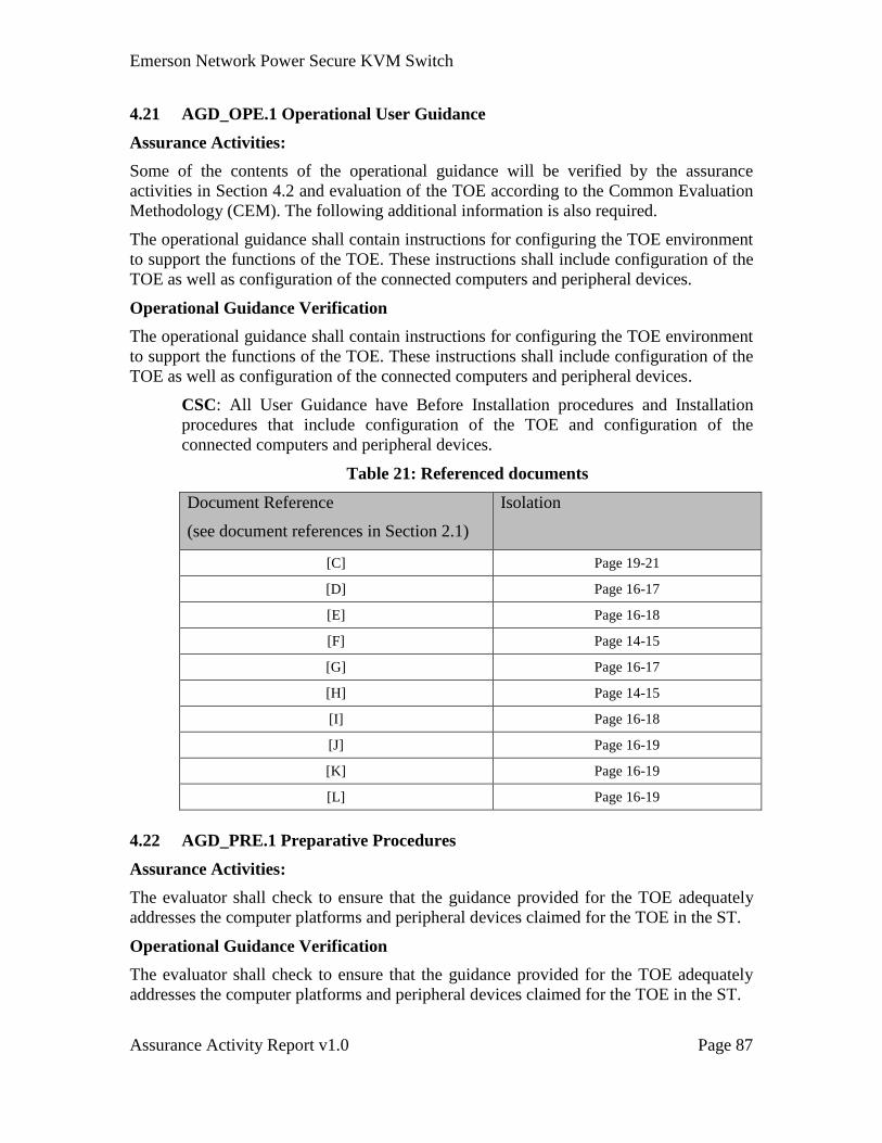
Emerson Network Power Secure KVM Switch
Assurance Activity Report v1.0 Page 87
4.21 AGD_OPE.1 Operational User Guidance
Assurance Activities:
Some of the contents of the operational guidance will be verified by the assurance
activities in Section 4.2 and evaluation of the TOE according to the Common Evaluation
Methodology (CEM). The following additional information is also required.
The operational guidance shall contain instructions for configuring the TOE environment
to support the functions of the TOE. These instructions shall include configuration of the
TOE as well as configuration of the connected computers and peripheral devices.
Operational Guidance Verification
The operational guidance shall contain instructions for configuring the TOE environment
to support the functions of the TOE. These instructions shall include configuration of the
TOE as well as configuration of the connected computers and peripheral devices.
CSC: All User Guidance have Before Installation procedures and Installation
procedures that include configuration of the TOE and configuration of the
connected computers and peripheral devices.
Table 21: Referenced documents
Document Reference
(see document references in Section 2.1)
Isolation
[C] Page 19-21
[D] Page 16-17
[E] Page 16-18
[F] Page 14-15
[G] Page 16-17
[H] Page 14-15
[I] Page 16-18
[J] Page 16-19
[K] Page 16-19
[L] Page 16-19
4.22 AGD_PRE.1 Preparative Procedures
Assurance Activities:
The evaluator shall check to ensure that the guidance provided for the TOE adequately
addresses the computer platforms and peripheral devices claimed for the TOE in the ST.
Operational Guidance Verification
The evaluator shall check to ensure that the guidance provided for the TOE adequately
addresses the computer platforms and peripheral devices claimed for the TOE in the ST.
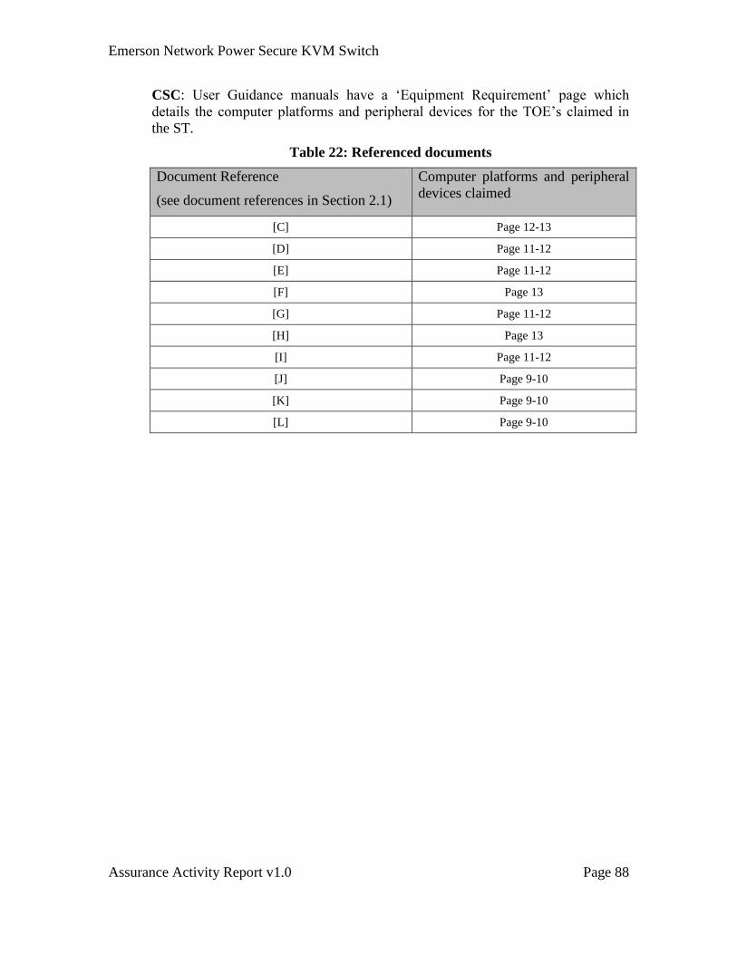
Emerson Network Power Secure KVM Switch
Assurance Activity Report v1.0 Page 88
CSC: User Guidance manuals have a ‘Equipment Requirement’ page which
details the computer platforms and peripheral devices for the TOE’s claimed in
the ST.
Table 22: Referenced documents
Document Reference
(see document references in Section 2.1)
Computer platforms and peripheral
devices claimed
[C] Page 12-13
[D] Page 11-12
[E] Page 11-12
[F] Page 13
[G] Page 11-12
[H] Page 13
[I] Page 11-12
[J] Page 9-10
[K] Page 9-10
[L] Page 9-10
Emerson Network Power Secure KVM Switch
Assurance Activity Report v1.0 Page 89
4.23 ATE_IND.1 Independent Testing - Conformance
Assurance Activities:
The evaluator shall prepare a test plan and report documenting the testing aspects of the
system. The test plan covers all of the testing actions contained in the CEM and the body
of this PP’s Assurance Activities. While it is not necessary to have one test case per test
listed in an Assurance Activity, the evaluator must document in the test plan that each
applicable testing requirement in the PP is covered.
The test plan identifies the platforms to be tested, and for those platforms not included in
the test plan but included in the ST, the test plan provides a justification for not testing
the platforms. This justification must address the differences between the tested platforms
and the untested platforms and make an argument that the differences do not affect the
testing to be performed. It is not sufficient to merely assert that the differences have no
affect; rationale must be provided. If all platforms claimed in the ST are tested, then no
rationale is necessary.
The test plan describes the composition of each platform to be tested and any setup that is
necessary beyond what is contained in the AGD documentation. It should be noted that
the evaluator is expected to follow the AGD documentation for installation and setup of
each platform either as part of a test or as a standard pre-test condition. This may include
special test equipment or tools. For each piece of equipment or tool, an argument (not just
an assertion) should be provided that the equipment or tool will not adversely affect the
performance of the functionality by the TOE and its platform.
The test plan identifies high-level test objectives as well as the test procedures to be
followed to achieve those objectives. These procedures include expected results. The test
report (which could just be an annotated version of the test plan) details the activities that
took place when the test procedures were executed, and includes the actual results of the
tests. This shall be a cumulative account, so if there was a test run that resulted in a
failure; a fix installed; and then a successful re-run of the test, the report would show a
“fail” and “pass” result (and the supporting details), and not just the “pass” result.
Testing Summary
While it is not necessary to have one test case per test listed in an Assurance Activity, the
evaluator must document in the test plan that each applicable testing requirement in the
PP is covered.
CSC: The test cases conducted in testing were organized exactly as presented in
the PP. For example, test case 4.1 in the actual testing replicates exactly test case
4.1 from the PP, including all test steps presented in the PP.
The test plan describes the composition of each platform to be tested and any setup that is
necessary beyond what is contained in the AGD documentation. It should be noted that
the evaluator is expected to follow the AGD documentation for installation and setup of
each platform either as part of a test or as a standard pre-test condition.
CSC: Sections 3.2 and 3.3 of this document describe each platform tested, what
tools and what setup was necessary for that platform.
Emerson Network Power Secure KVM Switch
Assurance Activity Report v1.0 Page 90
This may include special test equipment or tools. For each piece of equipment or tool, an
argument (not just an assertion) should be provided that the equipment or tool will not
adversely affect the performance of the functionality by the TOE and its platform.
CSC: Summarize testing tools and how the tools do not affect TOE
The test plan identifies high-level test objectives as well as the test procedures to be
followed to achieve those objectives. These procedures include expected results. The test
report (which could just be an annotated version of the test plan) details the activities that
took place when the test procedures were executed, and includes the actual results of the
tests. This shall be a cumulative account, so if there was a test run that resulted in a
failure; a fix installed; and then a successful re-run of the test, the report would show a
“fail” and “pass” result (and the supporting details), and not just the “pass” result.
CSC: The actual test cases executed are provided in a separate document. The
testing is replicated from the PP along with all actual results from the testing.
Each of the assurance activities in the SFRs above provide a summarization of the
testing conducted along with a sample of pictures of important test steps to show
representation of how testing was conducted.

Emerson Network Power Secure KVM Switch
Assurance Activity Report v1.0 Page 91
4.24 ALC_CMC.1 Labeling of the TOE
Assurance Activities:
The evaluator shall check the ST to ensure that it contains an identifier (such as a product
name/version number) that specifically identifies the version that meets the requirements
of the ST. Further, the evaluator shall check the AGD guidance and TOE samples
received for testing to ensure that the version number is consistent with that in the ST. If
the vendor maintains a web site advertising the TOE, the evaluator shall examine the
information on the web site to ensure that the information in the ST is sufficient to
distinguish the product.
Additionally, the evaluator shall verify that the labels required by FPT_PHP.1 are present
and intact, as follows:
1) The TOE is labeled with at least one unique identifying tamper-evident
marking (such as unique serial number) that can be used to authenticate
the device.
2) Tamper evident labels have been placed in critical locations on the TOE
enclosure to assure that any attempt to open the enclosure enough to gain
access to its internal components will change at least one label to a
tampered state.
3) at least one tamper evident label is placed in a location that will be visible
to the user operating the TOE.
TSS Verification
The evaluator shall check the ST to ensure that it contains an identifier (such as a product
name/version number) that specifically identifies the version that meets the requirements
of the ST.
CSC: In the ST, Table 2 in Section 1.3.2.1 identifies every switch in the
evaluation along with a unique part number and unique evaluation version
(33333-C4C4).
Operational Guidance Verification
Further, the evaluator shall check the AGD guidance and TOE samples received for
testing to ensure that the version number is consistent with that in the ST.
CSC: Each of the switches delivered to the user has a switch version number
stamped on a plate. The version number is the same format in the ST.
Additionally the samples delivered to the lab for testing were verified against the
ST. The picture below is an example of the SC945D Switch with a version of
33333-C4C4, which matches row 19 in table 2 of the ST for the switch. The test
report contains pictures of all version of switches provided for testing.
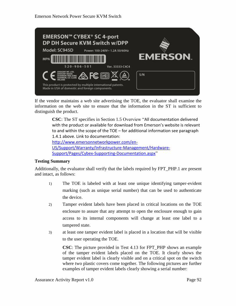
Emerson Network Power Secure KVM Switch
Assurance Activity Report v1.0 Page 92
If the vendor maintains a web site advertising the TOE, the evaluator shall examine the
information on the web site to ensure that the information in the ST is sufficient to
distinguish the product.
CSC: The ST specifies in Section 1.5 Overview “All documentation delivered with the product or available for download from Emerson’s website is relevant to and within the scope of the TOE – for additional information see paragraph 1.4.1 above. Link to documentation: http://www.emersonnetworkpower.com/en-US/Support/Warranty/Infrastructure-Management/Hardware-Support/Pages/Cybex-Supporting-Documentation.aspx”
Testing Summary
Additionally, the evaluator shall verify that the labels required by FPT_PHP.1 are present
and intact, as follows:
1) The TOE is labeled with at least one unique identifying tamper-evident
marking (such as unique serial number) that can be used to authenticate
the device.
2) Tamper evident labels have been placed in critical locations on the TOE
enclosure to assure that any attempt to open the enclosure enough to gain
access to its internal components will change at least one label to a
tampered state.
3) at least one tamper evident label is placed in a location that will be visible
to the user operating the TOE.
CSC: The picture provided in Test 4.13 for FPT_PHP shows an example
of the tamper evident labels placed on the TOE. It clearly shows the
tamper evident label is clearly visible and on a critical spot on the switch
where two plastic covers come together. The following pictures are further
examples of tamper evident labels clearly showing a serial number:
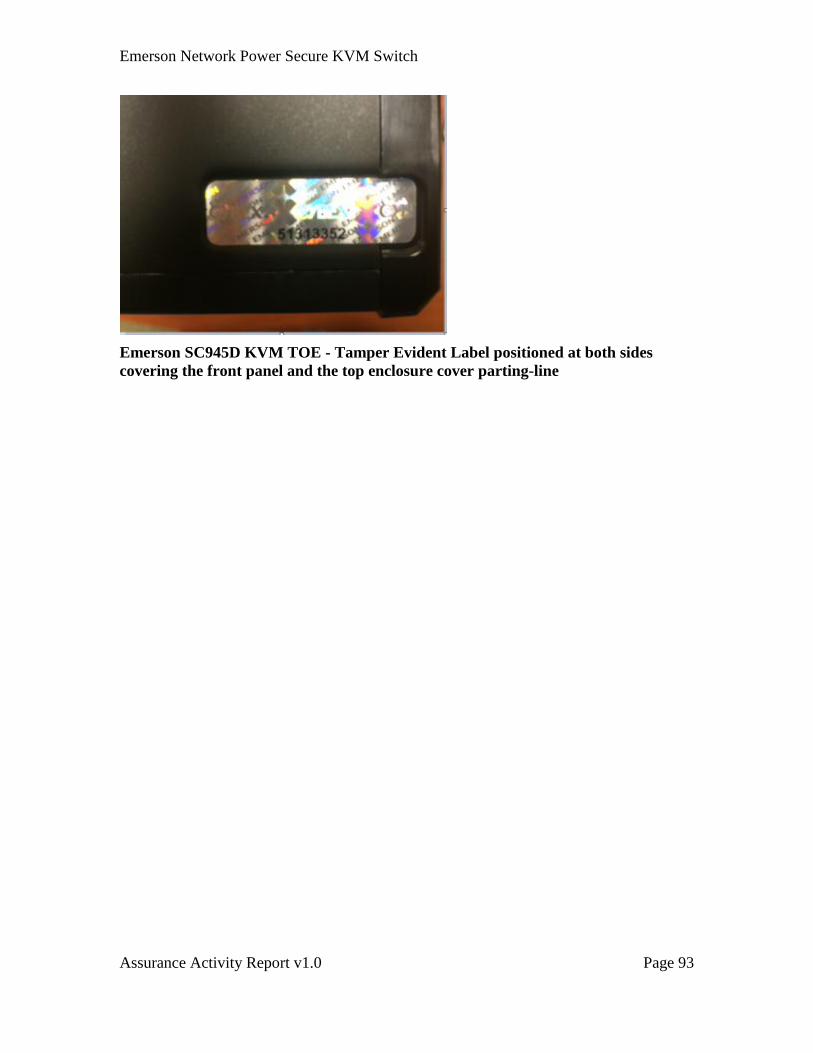
Emerson Network Power Secure KVM Switch
Assurance Activity Report v1.0 Page 93
Emerson SC945D KVM TOE - Tamper Evident Label positioned at both sides
covering the front panel and the top enclosure cover parting-line
Emerson Network Power Secure KVM Switch
Assurance Activity Report v1.0 Page 94
4.25 ALC_CMS.1 TOE CM Coverage
Assurance Activities:
The “evaluation evidence required by the SARs” in this PP is limited to the information
in the ST coupled with the guidance provided to administrators and users under the AGD
requirements. By ensuring that the TOE is specifically identified and that this
identification is consistent in the ST and in the AGD guidance (as done in the assurance
activity for ALC_CMC.1), the evaluator implicitly confirms the information required by
this component.
Emerson Network Power Secure KVM Switch
Assurance Activity Report v1.0 Page 95
5 Conclusions and Recommendations
The overall verdict for the evaluation is PASS, hence, it is concluded that the TOE in its
evaluated configuration meets all Peripheral Switch Protection Profile requirements.
The evaluators recommend that the consumers of this product understand and use all of
the appropriate secure configuration requirements recommended in each of the user
guidance documents provided to ensure that the secure configuration is achieved.
Emerson Network Power Secure KVM Switch
Assurance Activity Report v1.0 Page 96
6 List of Evaluation Evidence
1. Emerson Secure KVM and Matrix Security Target, version 3.18
2. EMERSON 2-PORT DH KVM User Manual PP3, Rev E
3. EMERSON 2-PORT SH KVM User Manual PP3, Rev E
4. EMERSON 4-PORT DH KVM User Manual PP3, Rev E
5. EMERSON 4-PORT SH KVM User Manual PP3, Rev E
6. EMERSON 2-Port Mini-Matrix User Manual PP3, Rev E
7. EMERSON 4-Port Mini-Matrix User Manual PP3, Rev E
8. EMERSON MIXED DUAL 2-PORT KVM User Manual PP3, Rev E
9. EMERSON MIXED DUAL 4-PORT KVM User Manual PP3, Rev E
10. EMERSON 8/16-Port Secure KVM User Manual PP3, Rev E
11. EMERSON MIXED TRIPLE 4-PORT KVM User Manual PP3, Rev E
12. Emerson DPP Configuration Manual, Rev C
13. Emerson Administrator Guide, Rev C
14. Isolation Documentation Emerson KVM Switch, KM, Isolator and Multi-viewer
KVM, version 3.01
15. Letter of Volatility – Emerson Secure KVM and Matrix, Rev C
Emerson Network Power Secure KVM Switch
Assurance Activity Report v1.0 Page 97
7 Product Compliance Listing Entry
Provided as a separate document
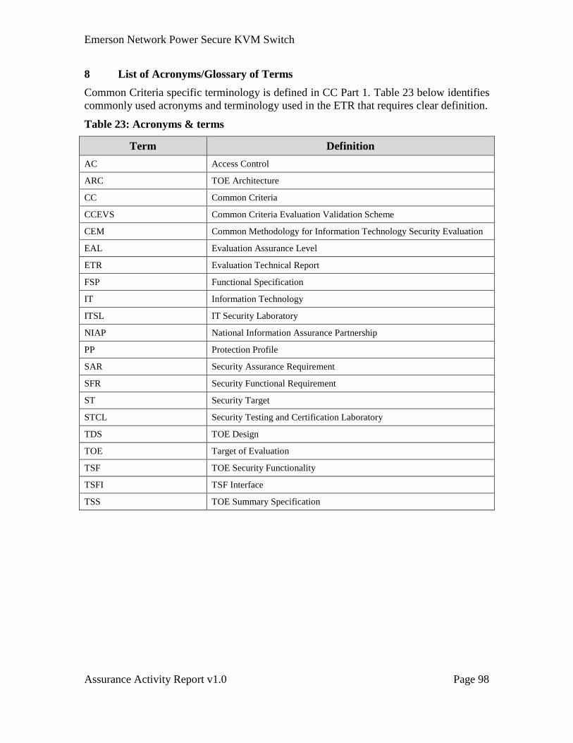
Emerson Network Power Secure KVM Switch
Assurance Activity Report v1.0 Page 98
8 List of Acronyms/Glossary of Terms
Common Criteria specific terminology is defined in CC Part 1. Table 23 below identifies
commonly used acronyms and terminology used in the ETR that requires clear definition.
Table 23: Acronyms & terms
Term Definition
AC Access Control
ARC TOE Architecture
CC Common Criteria
CCEVS Common Criteria Evaluation Validation Scheme
CEM Common Methodology for Information Technology Security Evaluation
EAL Evaluation Assurance Level
ETR Evaluation Technical Report
FSP Functional Specification
IT Information Technology
ITSL IT Security Laboratory
NIAP National Information Assurance Partnership
PP Protection Profile
SAR Security Assurance Requirement
SFR Security Functional Requirement
ST Security Target
STCL Security Testing and Certification Laboratory
TDS TOE Design
TOE Target of Evaluation
TSF TOE Security Functionality
TSFI TSF Interface
TSS TOE Summary Specification
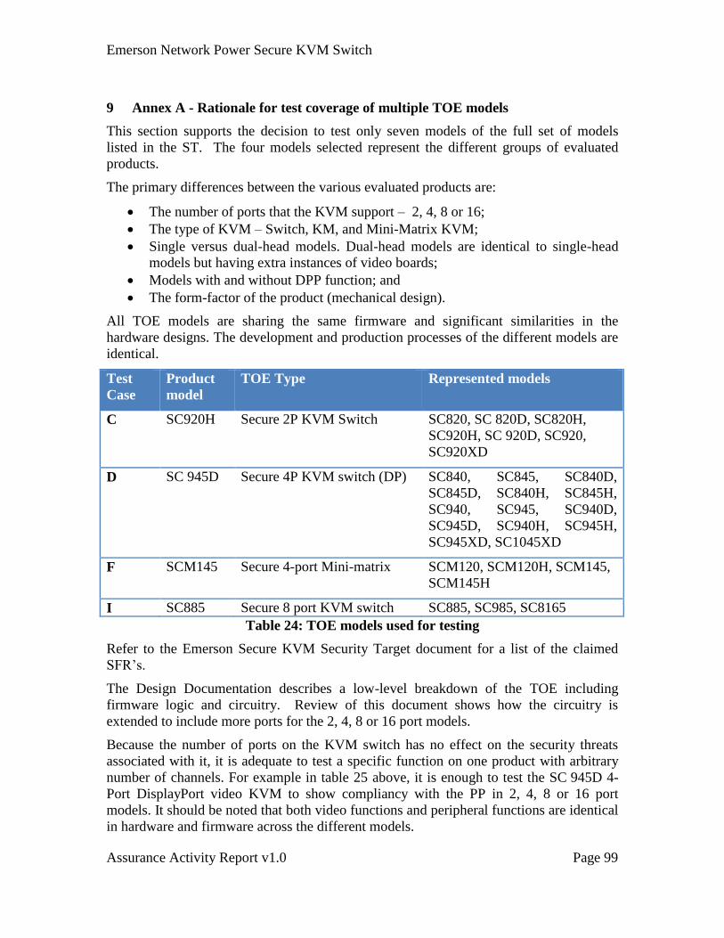
Emerson Network Power Secure KVM Switch
Assurance Activity Report v1.0 Page 99
9 Annex A - Rationale for test coverage of multiple TOE models
This section supports the decision to test only seven models of the full set of models
listed in the ST. The four models selected represent the different groups of evaluated
products.
The primary differences between the various evaluated products are:
The number of ports that the KVM support – 2, 4, 8 or 16;
The type of KVM – Switch, KM, and Mini-Matrix KVM;
Single versus dual-head models. Dual-head models are identical to single-head
models but having extra instances of video boards;
Models with and without DPP function; and
The form-factor of the product (mechanical design).
All TOE models are sharing the same firmware and significant similarities in the
hardware designs. The development and production processes of the different models are
identical.
Test
Case
Product
model
TOE Type Represented models
C SC920H Secure 2P KVM Switch SC820, SC 820D, SC820H,
SC920H, SC 920D, SC920,
SC920XD
D SC 945D Secure 4P KVM switch (DP) SC840, SC845, SC840D,
SC845D, SC840H, SC845H,
SC940, SC945, SC940D,
SC945D, SC940H, SC945H,
SC945XD, SC1045XD
F SCM145 Secure 4-port Mini-matrix SCM120, SCM120H, SCM145,
SCM145H
I SC885 Secure 8 port KVM switch SC885, SC985, SC8165
Table 24: TOE models used for testing
Refer to the Emerson Secure KVM Security Target document for a list of the claimed
SFR’s.
The Design Documentation describes a low-level breakdown of the TOE including
firmware logic and circuitry. Review of this document shows how the circuitry is
extended to include more ports for the 2, 4, 8 or 16 port models.
Because the number of ports on the KVM switch has no effect on the security threats
associated with it, it is adequate to test a specific function on one product with arbitrary
number of channels. For example in table 25 above, it is enough to test the SC 945D 4-
Port DisplayPort video KVM to show compliancy with the PP in 2, 4, 8 or 16 port
models. It should be noted that both video functions and peripheral functions are identical
in hardware and firmware across the different models.
Emerson Network Power Secure KVM Switch
Assurance Activity Report v1.0 Page 100
DisplayPort requires special testing based on the referenced PP and therefore the 4-Port
SC 945D selected as a representative model for this group of products. It should be
noted here that the same video board used in the SC945D is used in all other DP video
products.
This document describes the testing procedure for the 4 models that are listed in table 25
above. The scope of the test plans includes only the claimed SFR’s, which are identical
for each model of the KVM switch. Each test case verifies one or more SFR’s in the
Security Target. The only model specific test cases are those that iterate through each
computer in order to verify that each port is working as intended. The test cases can be
applied to any model of the KVM by changing the number of computers tested.
Based on the design presented in the ST, and the test cases defined in this document,
there are no aspects of the different models that are not covered in testing a single model.
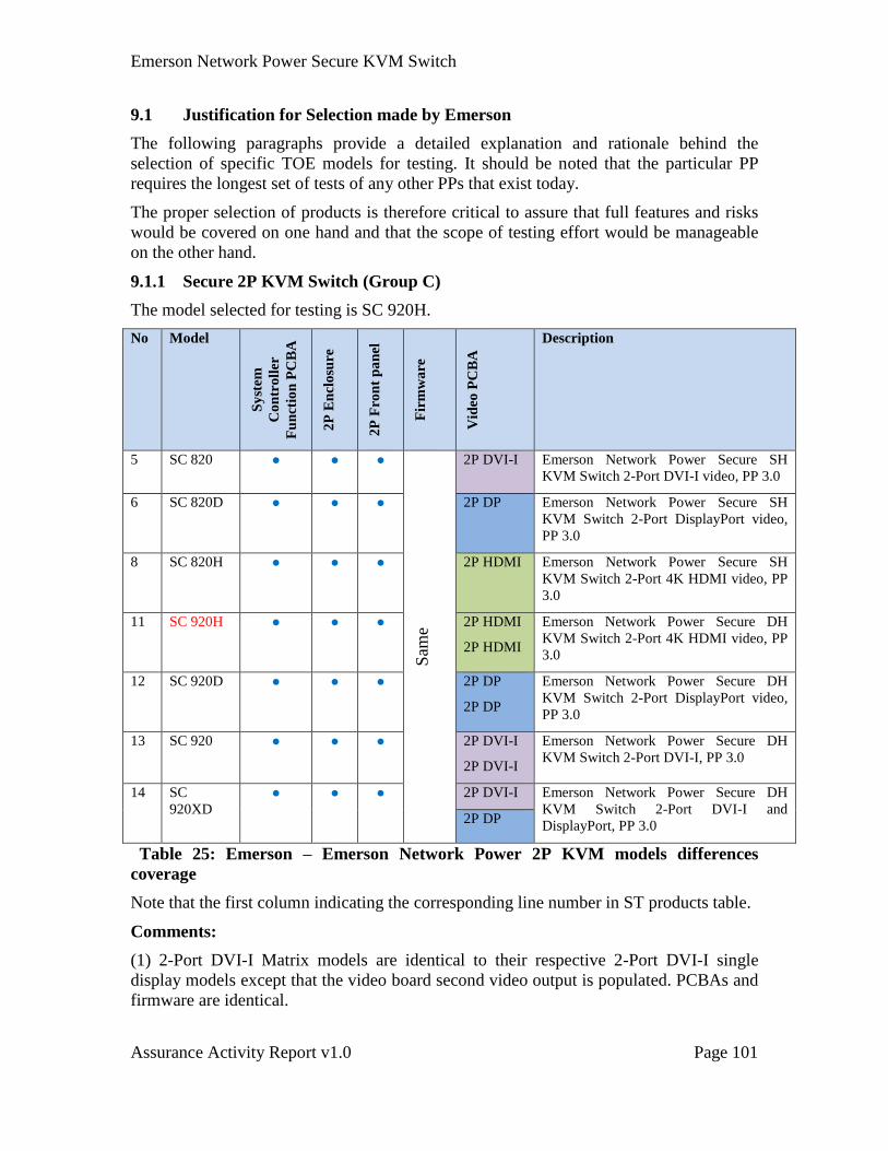
Emerson Network Power Secure KVM Switch
Assurance Activity Report v1.0 Page 101
9.1 Justification for Selection made by Emerson
The following paragraphs provide a detailed explanation and rationale behind the
selection of specific TOE models for testing. It should be noted that the particular PP
requires the longest set of tests of any other PPs that exist today.
The proper selection of products is therefore critical to assure that full features and risks
would be covered on one hand and that the scope of testing effort would be manageable
on the other hand.
9.1.1 Secure 2P KVM Switch (Group C)
The model selected for testing is SC 920H.
No Model
Sy
stem
Co
ntr
oll
er
Fu
nct
ion
PC
BA
2P
En
clo
sure
2P
Fro
nt
pa
nel
Fir
mw
are
Vid
eo P
CB
A
Description
5 SC 820 ● ● ●
Sam
e
2P DVI-I Emerson Network Power Secure SH
KVM Switch 2-Port DVI-I video, PP 3.0
6 SC 820D ● ● ● 2P DP Emerson Network Power Secure SH
KVM Switch 2-Port DisplayPort video,
PP 3.0
8 SC 820H ● ● ● 2P HDMI Emerson Network Power Secure SH
KVM Switch 2-Port 4K HDMI video, PP
3.0
11 SC 920H ● ● ● 2P HDMI
2P HDMI
Emerson Network Power Secure DH
KVM Switch 2-Port 4K HDMI video, PP
3.0
12 SC 920D ● ● ● 2P DP
2P DP
Emerson Network Power Secure DH
KVM Switch 2-Port DisplayPort video,
PP 3.0
13 SC 920 ● ● ● 2P DVI-I
2P DVI-I
Emerson Network Power Secure DH
KVM Switch 2-Port DVI-I, PP 3.0
14 SC
920XD ● ● ● 2P DVI-I Emerson Network Power Secure DH
KVM Switch 2-Port DVI-I and
DisplayPort, PP 3.0 2P DP
Table 25: Emerson – Emerson Network Power 2P KVM models differences
coverage
Note that the first column indicating the corresponding line number in ST products table.
Comments:
(1) 2-Port DVI-I Matrix models are identical to their respective 2-Port DVI-I single
display models except that the video board second video output is populated. PCBAs and
firmware are identical.

Emerson Network Power Secure KVM Switch
Assurance Activity Report v1.0 Page 102
(2) 2-Port HDMI Matrix models are identical to their respective 2-Port HDMI single
display models except that the video board second video output is populated. PCBAs and
firmware are identical.
(3) 2-Port mini-matrix models are having additional push-buttons and LEDs on their front
panels.
(4) KM TOE is having a smaller (scaled down) version enclosure design as no video
board installed. Front panel and anti-tampering features are identical to the bigger 2-Port
enclosures.
(5) 2-Port DH (Dual Head) models are having additional video board instance and
therefore their enclosure is slightly bigger (extending vertically). Other than that the
enclosure design is identical to all other 2P models.
The 2P KM / KVM product line is using a common form-factor and common system
controller board. Since almost all security and control functions are contained in that
board, the products are essentially identical. The only significant differences between
models are in the video board – the type of video protocol supported, and the number of
instances installed from the same / different board.
The video board is responsible only for the video related security functions and it
communicate through a unidirectional link with the system controller board and therefore
in general it is enough to test the system controller of one 2-Port model.
Video boards of the 2-Port models are identical in design to the 4-Port and 8-Port and
therefore video security function may be easily covered by other tested models.
In general since the 2-Port models are scaled down versions of the 4-Port models, it is
assumed that most special features would be better covered by testing the similar 4-Port
models:
Testing of mini-matrix unique functions is already covered by other group (F - 4-
Port) and therefore not needed for 2-Port.
Testing of KM unique functions is already covered by other group (E - 4-Port)
and therefore not needed for 2-Port.
Testing of KVM Combiner unique functions is already covered by other group (H
- 4-Port) and therefore not needed for 2-Port.
Testing of DisplayPort video unique functions is already covered by other group
(D - 4-Port) and therefore not needed for 2-Port.
Alternative potential approach proposed was to test in addition to the system controller
function, only the video function of each one of the 2-Port models based on the colors in
the table above. Still we believe that it is better to test a complete product and not just
functions and that the additional test work would not generate any additional information
/ assurance.
We decided to select a Dual Head KVM (as it is a superset of two video board and one
system controller board). The selection of HDMI was arbitrary here – we wanted to make
sure that each video protocol will be tested by at least one product group.
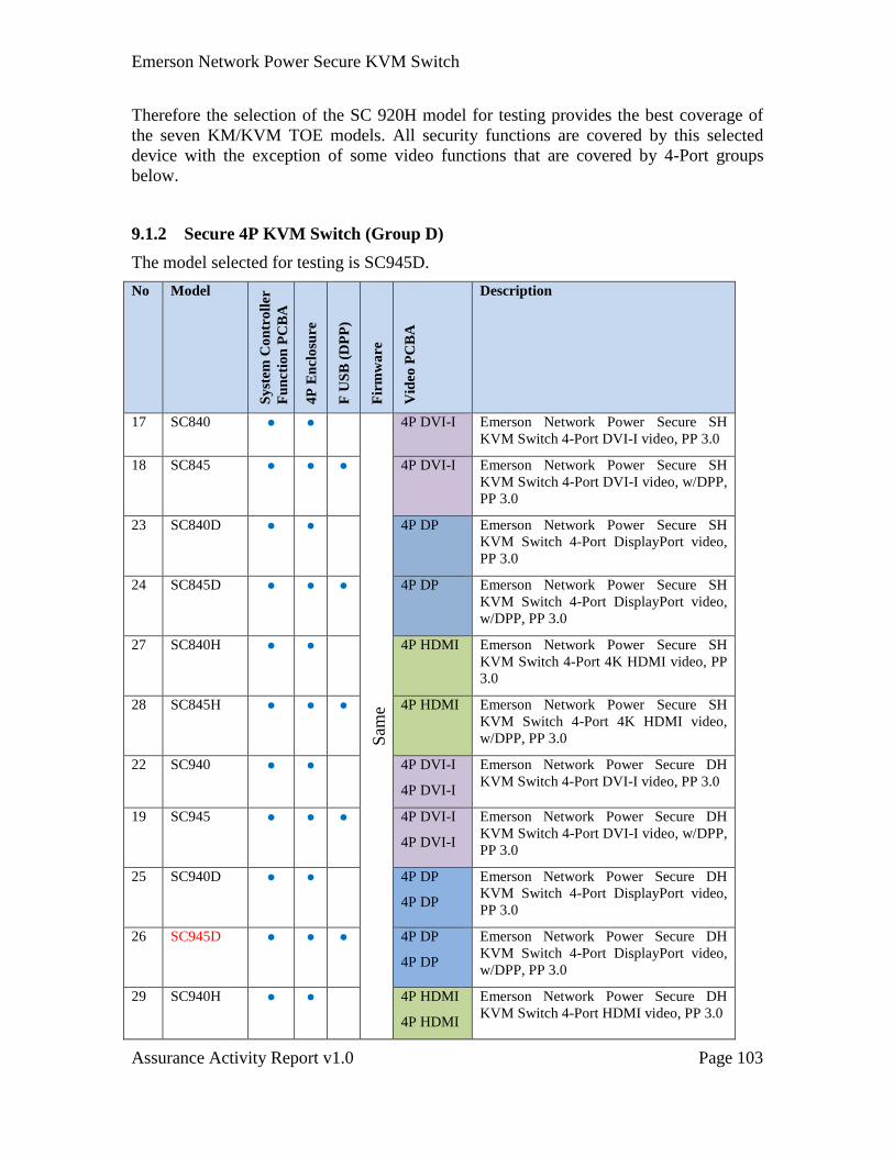
Emerson Network Power Secure KVM Switch
Assurance Activity Report v1.0 Page 103
Therefore the selection of the SC 920H model for testing provides the best coverage of
the seven KM/KVM TOE models. All security functions are covered by this selected
device with the exception of some video functions that are covered by 4-Port groups
below.
9.1.2 Secure 4P KVM Switch (Group D)
The model selected for testing is SC945D.
No Model
Sy
stem
Co
ntr
oll
er
Fu
nct
ion
PC
BA
4P
En
clo
sure
F U
SB
(D
PP
)
(d
Fir
mw
are
Vid
eo P
CB
A
Description
17 SC840 ● ●
Sam
e
4P DVI-I Emerson Network Power Secure SH
KVM Switch 4-Port DVI-I video, PP 3.0
18 SC845 ● ● ● 4P DVI-I Emerson Network Power Secure SH
KVM Switch 4-Port DVI-I video, w/DPP,
PP 3.0
23 SC840D ● ● 4P DP Emerson Network Power Secure SH
KVM Switch 4-Port DisplayPort video,
PP 3.0
24 SC845D ● ● ● 4P DP Emerson Network Power Secure SH
KVM Switch 4-Port DisplayPort video,
w/DPP, PP 3.0
27 SC840H ● ● 4P HDMI Emerson Network Power Secure SH
KVM Switch 4-Port 4K HDMI video, PP
3.0
28 SC845H ● ● ● 4P HDMI Emerson Network Power Secure SH
KVM Switch 4-Port 4K HDMI video,
w/DPP, PP 3.0
22 SC940 ● ● 4P DVI-I
4P DVI-I
Emerson Network Power Secure DH
KVM Switch 4-Port DVI-I video, PP 3.0
19 SC945 ● ● ● 4P DVI-I
4P DVI-I
Emerson Network Power Secure DH
KVM Switch 4-Port DVI-I video, w/DPP,
PP 3.0
25 SC940D ● ● 4P DP
4P DP
Emerson Network Power Secure DH
KVM Switch 4-Port DisplayPort video,
PP 3.0
26 SC945D ● ● ● 4P DP
4P DP
Emerson Network Power Secure DH
KVM Switch 4-Port DisplayPort video,
w/DPP, PP 3.0
29 SC940H ● ● 4P HDMI
4P HDMI
Emerson Network Power Secure DH
KVM Switch 4-Port HDMI video, PP 3.0
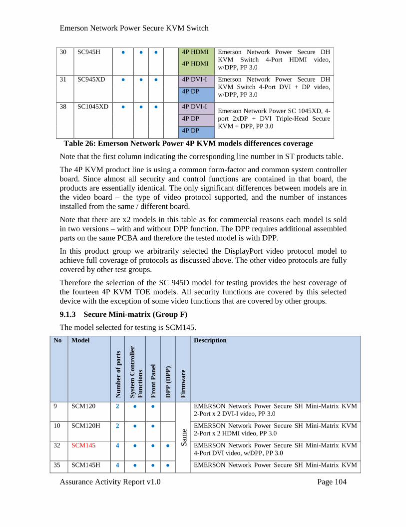
Emerson Network Power Secure KVM Switch
Assurance Activity Report v1.0 Page 104
30 SC945H ● ● ● 4P HDMI
4P HDMI
Emerson Network Power Secure DH
KVM Switch 4-Port HDMI video,
w/DPP, PP 3.0
31 SC945XD ● ● ● 4P DVI-I Emerson Network Power Secure DH
KVM Switch 4-Port DVI + DP video,
w/DPP, PP 3.0 4P DP
38 SC1045XD ● ● ● 4P DVI-I Emerson Network Power SC 1045XD, 4-
port 2xDP + DVI Triple-Head Secure
KVM + DPP, PP 3.0
4P DP
4P DP
Table 26: Emerson Network Power 4P KVM models differences coverage
Note that the first column indicating the corresponding line number in ST products table.
The 4P KVM product line is using a common form-factor and common system controller
board. Since almost all security and control functions are contained in that board, the
products are essentially identical. The only significant differences between models are in
the video board – the type of video protocol supported, and the number of instances
installed from the same / different board.
Note that there are x2 models in this table as for commercial reasons each model is sold
in two versions – with and without DPP function. The DPP requires additional assembled
parts on the same PCBA and therefore the tested model is with DPP.
In this product group we arbitrarily selected the DisplayPort video protocol model to
achieve full coverage of protocols as discussed above. The other video protocols are fully
covered by other test groups.
Therefore the selection of the SC 945D model for testing provides the best coverage of
the fourteen 4P KVM TOE models. All security functions are covered by this selected
device with the exception of some video functions that are covered by other groups.
9.1.3 Secure Mini-matrix (Group F)
The model selected for testing is SCM145.
No Model
Nu
mb
er o
f p
ort
s
Sy
stem
Co
ntr
oll
er
Fu
nct
ion
s
Fro
nt
Pa
nel
DP
P (
DP
P)
(d
Fir
mw
are
Description
9 SCM120 2 ● ●
Sam
e
EMERSON Network Power Secure SH Mini-Matrix KVM
2-Port x 2 DVI-I video, PP 3.0
10 SCM120H 2 ● ● EMERSON Network Power Secure SH Mini-Matrix KVM
2-Port x 2 HDMI video, PP 3.0
32 SCM145 4 ● ● ● EMERSON Network Power Secure SH Mini-Matrix KVM
4-Port DVI video, w/DPP, PP 3.0
35 SCM145H 4 ● ● ● EMERSON Network Power Secure SH Mini-Matrix KVM
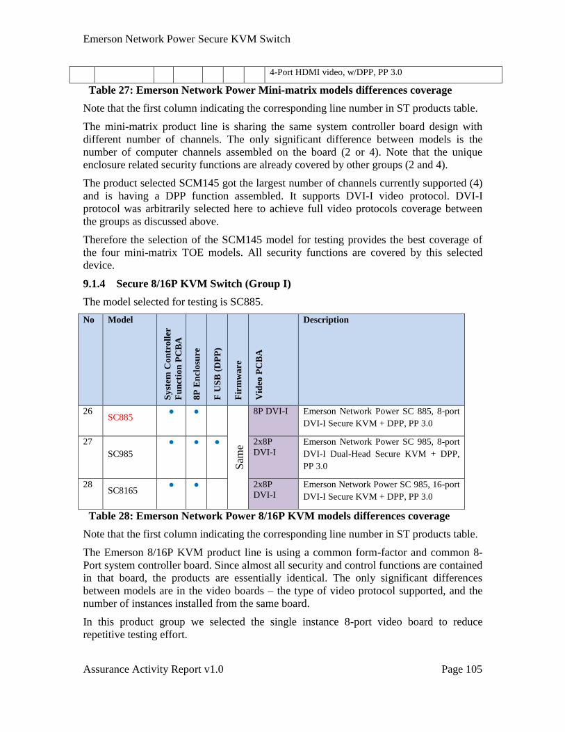
Emerson Network Power Secure KVM Switch
Assurance Activity Report v1.0 Page 105
4-Port HDMI video, w/DPP, PP 3.0
Table 27: Emerson Network Power Mini-matrix models differences coverage
Note that the first column indicating the corresponding line number in ST products table.
The mini-matrix product line is sharing the same system controller board design with
different number of channels. The only significant difference between models is the
number of computer channels assembled on the board (2 or 4). Note that the unique
enclosure related security functions are already covered by other groups (2 and 4).
The product selected SCM145 got the largest number of channels currently supported (4)
and is having a DPP function assembled. It supports DVI-I video protocol. DVI-I
protocol was arbitrarily selected here to achieve full video protocols coverage between
the groups as discussed above.
Therefore the selection of the SCM145 model for testing provides the best coverage of
the four mini-matrix TOE models. All security functions are covered by this selected
device.
9.1.4 Secure 8/16P KVM Switch (Group I)
The model selected for testing is SC885.
No Model
Sy
stem
Co
ntr
oll
er
Fu
nct
ion
PC
BA
8P
En
clo
sure
F U
SB
(D
PP
)
(d
Fir
mw
are
Vid
eo P
CB
A
Description
26 SC885
● ●
Sam
e
8P DVI-I Emerson Network Power SC 885, 8-port
DVI-I Secure KVM + DPP, PP 3.0
27
SC985
● ● ● 2x8P
DVI-I
Emerson Network Power SC 985, 8-port
DVI-I Dual-Head Secure KVM + DPP,
PP 3.0
28 SC8165
● ● 2x8P
DVI-I Emerson Network Power SC 985, 16-port
DVI-I Secure KVM + DPP, PP 3.0
Table 28: Emerson Network Power 8/16P KVM models differences coverage
Note that the first column indicating the corresponding line number in ST products table.
The Emerson 8/16P KVM product line is using a common form-factor and common 8-
Port system controller board. Since almost all security and control functions are contained
in that board, the products are essentially identical. The only significant differences
between models are in the video boards – the type of video protocol supported, and the
number of instances installed from the same board.
In this product group we selected the single instance 8-port video board to reduce
repetitive testing effort.
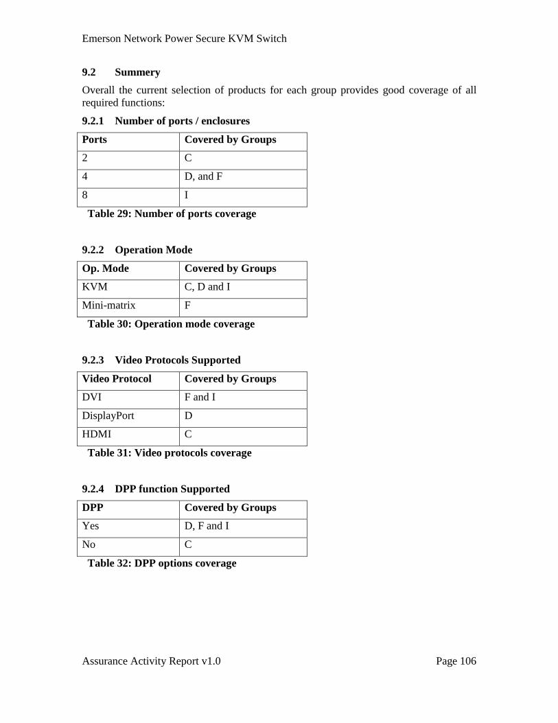
Emerson Network Power Secure KVM Switch
Assurance Activity Report v1.0 Page 106
9.2 Summery
Overall the current selection of products for each group provides good coverage of all
required functions:
9.2.1 Number of ports / enclosures
Ports Covered by Groups
2 C
4 D, and F
8 I
Table 29: Number of ports coverage
9.2.2 Operation Mode
Op. Mode Covered by Groups
KVM C, D and I
Mini-matrix F
Table 30: Operation mode coverage
9.2.3 Video Protocols Supported
Video Protocol Covered by Groups
DVI F and I
DisplayPort D
HDMI C
Table 31: Video protocols coverage
9.2.4 DPP function Supported
DPP Covered by Groups
Yes D, F and I
No C
Table 32: DPP options coverage