Embed Size (px)
Citation preview
Emerging Techniques in Vision-based
Indoor Localization
Feng HU
A literature review submitted to
the Graduate Faculty in Computer Science in partial fulfillment of
the requirements for the degree of Doctor of Philosophy,
The City University of New York
Committee Members:
Dr. Zhigang Zhu (Advisor)
Dr. Jizhong Xiao
Dr. Jianting Zhang
Feb 4, 2015

c© Copyright by Feng HU, 2015.
All rights reserved.
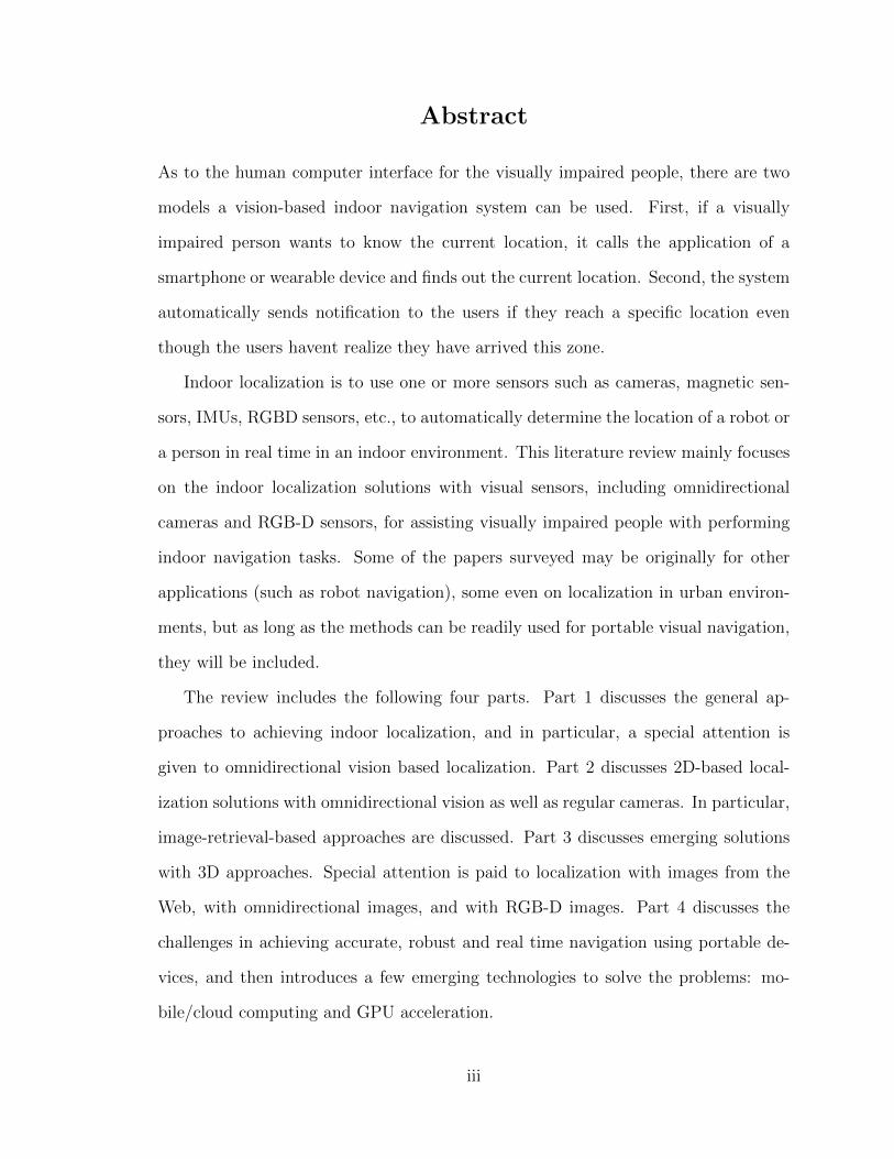
Abstract
As to the human computer interface for the visually impaired people, there are two
models a vision-based indoor navigation system can be used. First, if a visually
impaired person wants to know the current location, it calls the application of a
smartphone or wearable device and finds out the current location. Second, the system
automatically sends notification to the users if they reach a specific location even
though the users havent realize they have arrived this zone.
Indoor localization is to use one or more sensors such as cameras, magnetic sen-
sors, IMUs, RGBD sensors, etc., to automatically determine the location of a robot or
a person in real time in an indoor environment. This literature review mainly focuses
on the indoor localization solutions with visual sensors, including omnidirectional
cameras and RGB-D sensors, for assisting visually impaired people with performing
indoor navigation tasks. Some of the papers surveyed may be originally for other
applications (such as robot navigation), some even on localization in urban environ-
ments, but as long as the methods can be readily used for portable visual navigation,
they will be included.
The review includes the following four parts. Part 1 discusses the general ap-
proaches to achieving indoor localization, and in particular, a special attention is
given to omnidirectional vision based localization. Part 2 discusses 2D-based local-
ization solutions with omnidirectional vision as well as regular cameras. In particular,
image-retrieval-based approaches are discussed. Part 3 discusses emerging solutions
with 3D approaches. Special attention is paid to localization with images from the
Web, with omnidirectional images, and with RGB-D images. Part 4 discusses the
challenges in achieving accurate, robust and real time navigation using portable de-
vices, and then introduces a few emerging technologies to solve the problems: mo-
bile/cloud computing and GPU acceleration.
iii
Contents
Abstract . . . . . . . . . . . . . . . . . . . . . . . . . . . . . . . . . . . . . iii
1 Introduction 1
2 Indoor Localization: An overview 6
2.1 Bluetooth and RFID based localization . . . . . . . . . . . . . . . . . 6
2.2 WiFi based localization . . . . . . . . . . . . . . . . . . . . . . . . . . 8
2.3 Portable 2D/3D visual sensors based localization . . . . . . . . . . . 10
2.4 Omnidirectional vision-based localization . . . . . . . . . . . . . . . . 11
3 2D Image-based Approaches 14
3.1 Feature Extraction . . . . . . . . . . . . . . . . . . . . . . . . . . . . 15
3.1.1 Direct feature methods . . . . . . . . . . . . . . . . . . . . . . 15
3.1.2 Pooling methods . . . . . . . . . . . . . . . . . . . . . . . . . 19
3.2 Modeling via Indexing . . . . . . . . . . . . . . . . . . . . . . . . . . 22
3.2.1 Metric localization . . . . . . . . . . . . . . . . . . . . . . . . 23
3.2.2 Topological localization . . . . . . . . . . . . . . . . . . . . . . 25
3.3 Localization via Retrieval . . . . . . . . . . . . . . . . . . . . . . . . 27
3.3.1 One-step methods . . . . . . . . . . . . . . . . . . . . . . . . . 27
3.3.2 Multi-step methods . . . . . . . . . . . . . . . . . . . . . . . . 31
4 3D Model-based Approaches 33
iv
4.1 SfM-based localization . . . . . . . . . . . . . . . . . . . . . . . . . . 33
4.1.1 SfM localization with crowdsourced images . . . . . . . . . . . 34
4.1.2 SfM localization with self-collected database . . . . . . . . . . 39
4.1.3 The scale problem . . . . . . . . . . . . . . . . . . . . . . . . 40
4.2 3D sensor based methods . . . . . . . . . . . . . . . . . . . . . . . . . 40
4.2.1 RGBD based methods . . . . . . . . . . . . . . . . . . . . . . 43
4.2.2 Depth-only methods . . . . . . . . . . . . . . . . . . . . . . . 44
5 Challenging Issues and Emerging Solutions 46
5.1 Challenging Issues . . . . . . . . . . . . . . . . . . . . . . . . . . . . 46
5.1.1 System accuracy standard and sensor capacity . . . . . . . . . 47
5.1.2 Computational cost and real time performance . . . . . . . . . 48
5.1.3 System evaluation . . . . . . . . . . . . . . . . . . . . . . . . 49
5.2 Emerging technologies . . . . . . . . . . . . . . . . . . . . . . . . . . 50
5.2.1 Mobile platforms . . . . . . . . . . . . . . . . . . . . . . . . . 51
5.2.2 GPU acceleration . . . . . . . . . . . . . . . . . . . . . . . . 53
6 Conclusions and Discussions 57
v
Chapter 1
Introduction
Indoor localization is to use one or more sensors such as cameras, magnetic sensors,
IMUs, RGBD sensors, etc., to automatically determine the location of a robot or a
person in real time in an indoor environment. This literature review mainly focuses on
the indoor localization solutions with visual sensors—especially with omnidirectional
cameras—that are used or can be used for assisting visually impaired people with
performing indoor navigation tasks.
An indoor localization system is of significant importance to the visually impaired
in their daily lives by helping them localize themselves and further navigate indoor
environments. Updated until August 2014, there are 285 million visually impaired
people in the world (which is 4% of the whole population) according to the World
Health Organization 1, among who 39 million are blind. Compared to sighted peo-
ple, it is much harder for visually impaired people to navigate indoor environments.
Nowadays, too many buildings are unfortunately mainly designed and built for sighted
people; therefore, things which are not problematic for sighted people could be huge
barriers to visually impaired people. Finding a solution for helping visually impaired
people navigation is greatly needed.
1http://www.who.int/mediacentre/factsheets/fs282/en/
1
Finding the position of a visually impaired person can help him/her to get the de-
signed places, and this ability of free navigation is important for a normal social life.
Important places in a building include restrooms, stairs, elevators, public electronic
terminals, and building entrances and exits. The usual way for visually impaired
people to navigate indoor environments is by memorization, which means, by remem-
bering the already traveled route and recalling it when they come to the same place
the second time [38]. A lot of work is involved in this task. For example, they have
to precisely remember turn-by-turn information and all the important points of inter-
ests (i.e., landmarks) along the routes, like office numbers. These landmarks not only
provide them waypoints to help them judge whether they are on the correct path but
also serve directly as the destination.
However, it is possible to create and build assistive indoor navigation systems for
the visually impaired to relieve them from such memory burdens, and free their minds
to process other important issues in their daily life. The emergence of widely used
mobile/wearable devices, the great capability of computing power in these devices,
and recently advanced computer vision techniques make a promising potential for
localization solutions.
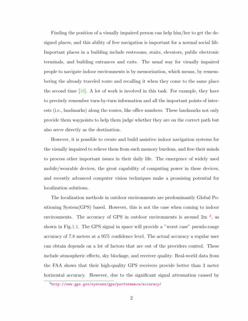
The localization methods in outdoor environments are predominantly Global Po-
sitioning System(GPS) based. However, this is not the case when coming to indoor
environments. The accuracy of GPS in outdoor environments is around 2m 2, as
shown in Fig.1.1. The GPS signal in space will provide a ”worst case” pseudo-range
accuracy of 7.8 meters at a 95% confidence level. The actual accuracy a regular user
can obtain depends on a lot of factors that are out of the providers control. These
include atmospheric effects, sky blockage, and receiver quality. Real-world data from
the FAA shows that their high-quality GPS receivers provide better than 3 meter
horizontal accuracy. However, due to the significant signal attenuation caused by
2http://www.gps.gov/systems/gps/performance/accuracy/
2
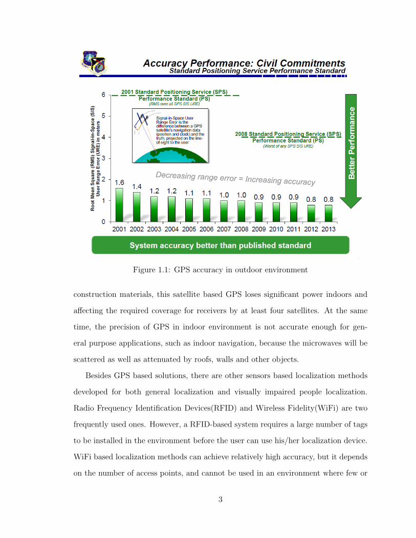
Figure 1.1: GPS accuracy in outdoor environment
construction materials, this satellite based GPS loses significant power indoors and
affecting the required coverage for receivers by at least four satellites. At the same
time, the precision of GPS in indoor environment is not accurate enough for gen-
eral purpose applications, such as indoor navigation, because the microwaves will be
scattered as well as attenuated by roofs, walls and other objects.
Besides GPS based solutions, there are other sensors based localization methods
developed for both general localization and visually impaired people localization.
Radio Frequency Identification Devices(RFID) and Wireless Fidelity(WiFi) are two
frequently used ones. However, a RFID-based system requires a large number of tags
to be installed in the environment before the user can use his/her localization device.
WiFi based localization methods can achieve relatively high accuracy, but it depends
on the number of access points, and cannot be used in an environment where few or
3

no internet routers are available. Meanwhile, the above two methods provide only
position coordinates, and therefore have limits in further navigation potential, such
as obstacle detection, sign recognition, etc., which are important for assistive services.
Before computer vision aided systems appearred, classical methods blind people
used to find their target locations necessary for daily living were to use tactile displays.
The public infrastructure of a city or an institution usually encodes the information of
locations (e.g. the names of the places) within tactile displays. A blind user makes use
of them by first finding them and then reading the braille. The disadvantage of this
method is that people have to come close to the braille before they can recognize it.
However because the visually impaired people has limited vision, to find the location
of the braille letters itself is a difficult task for them.
When computer vision technologies were first designed for this task, researchers
used similar approaches to display location information, i.e. first encoding the loca-
tion information into some specially designed signs, such QR codes, color markers
[27], etc., and allowing a blind user to find these signs with a portable device such
as a smart-phone [54][27][39], or, later, a Google Glass [1]. The advantage of using
computer vision aided methods is that it allows users to detect and decode the infor-
mation without touch. This eliminates the need for finding the position of the letters
and touching them to decode them. This enables blind users to acquire direction
information by just scanning the environment with the wearable device, similar to
the way sighted people used to get environmental assistive information by a simple
glance of the location’s name.
As to the human computer interface for visually impaired people, there are two
models a vision based indoor navigation system can use. First, if a visually impaired
person wants to know their current location, they call the application on a smart-
phone or wearable device and find out the current location. Second, the system
4
automatically sends notification to the user if they reach a specific location, even
though the user has not realized they have arrived at their goal.
The purpose of this survey is to look into possible solutions for assisting visually
impaired people. Some of the papers that are surveyed may be originally for other
applications (such as robot navigation), a few are on localization in urban environ-
ments, but as long as the methods can be readily used for indoor visual navigation,
they will be included. We will pay special attention to omnidirectional vision, since
omnidirectional sensors capture images with a 360-degree field of view coverage, and
are now becoming portable and very cost-effective.
The organization of this review is as follows. Chapter 2 discusses the general
approaches to achieving indoor localization and gives an overview of omnidirectional
vision based localization. Chapter 3 discusses 2D-based localization solutions with
omnidirectional visual sensors as well as regular cameras. Chapter 4 discusses the
solutions with 3D approaches of omnidirectional vision, regular cameras and depth
sensors. Chapter 5 discusses the challenges in achieving accurate, robust and real
time navigation using portable devices, and introduces a few emerging technologies
for solving the problems: mobile/cloud computing and GPU acceleration. Chapter 6
provides some concluding remarks and discussing.
5
Chapter 2
Indoor Localization: An overview
Localization systems, whether based on non-visual or visual information, need to
obtain data from a navigated environment with sensors as input. Sensing is the first
step to beginning a navigation task, which is followed by processing and analyzing
the obtained data with different kinds of computational methods. In this chapter, we
will first introduce some non-visual sensor based localization methods which might
be used or compared with vision-based solutions in a practical assistive navigation
system. After that, we turn to the vision sensor based localization methods, especially
the omnidirectional sensor and how it can be applied to localization and navigation
tasks.
2.1 Bluetooth and RFID based localization
The bluetooth technology is built to transfer data, but it is also capable of telling the
distance between the transmitter and the receiver. Many companies are doing beacon
based indoor navigation systems. For example, SPREO, a US and Israeli company,
founded in 2013 1, provides a bluetooth beacon signal based indoor navigation service,
and claims an accuracy of 1.5m.
1http://spreo.co/
6
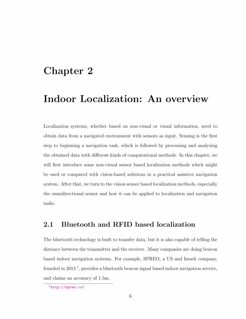
Figure 2.1: A sample bluetooth beacon
The bluetooth indoor navigation system usually involves two parts: the hardware
bluetooth beacons, and the mobile receivers, which are usually smart-phones, like
iPhones or Android phones. The beacons are low cost, low energy chips and the
battery can last for years (e.g. 5 years for Texas Instruments (TI) CC2540 Bluetooth
System-on-Chip beacons). Fig. 2.1 shows an example.
The smart-phone receives a signal from these beacons, and calculates the current
location, the floor number, related maps, and possibly zoom in and zoom out function-
ality. This information can be used for images/videos capture using the smart-phone
for door and sign detection and localization.
The Radio Frequency Identification(RFID) based indoor localization method is
another type of localization method. The idea is to use the electromagnetic field
wirelessly to transfer data to automatically identify and track tags attached to objects.
As opposed barcodes, RFID tags do not necessarily have to be within line of the sight
of a RFID reader, and may be embedded in a tracked object.
A RFID system uses labels or tags attached to the objects to be identified [8].
There is a bidirectional communication between a sender (also known as interrogator
or reader), which sends signal to a tag and reads its response, and a tag. Tags can be
passive, active or battery-assisted passive. The active tags have batteries built-in and
can periodically transmit their signals. The battery assisted passive tags have a small
battery inside but the battery is only activated when the tags are in the range of a
reader. The passive tags are small and cheap, but they require a signal magnitude
7
three times than the normal because they need to use the energy inside the signals
to transmit the data back to the reader.
In Chumkamon [8], the RFID tags are embedded into stone blocks and put onto
a footpath. By continuously detecting and tracking the RFID signal with a portable
RFID reader, the app can determine the current location by decoding the received
signals and looking it up in the database. Alternatively, each tag can be installed at
signposts along a pathway, footpath or at the junction of the footpath. The RFID tags
contain tag IDs and tag location information. Each location information is identified
by a location area, a path, a link, or a node in terms of longitude or latitude.
Both the bluetooth and RFID localization methods need to modify the envi-
ronment by attaching beacons or tags to function properly. When the localization
area expands, the cost would increase significantly, and therefore limit the scalability
of these methods. Meanwhile, changing the environment setting would arise other
issues, such as aesthetic issues or legal issues. In addition, the accuracy of the local-
ization depends on the number of sensors mounted—for example, number of beacons
or tags—this adds to the burden of installation and maintenance of these systems.
2.2 WiFi based localization
WiFi (also, Wi-Fi or Wifi) is a local area technology that allows an electronic device to
exchange data or connect to the internet using specific radio frequencies, e.g. 2.4GHz
UHF or 5GHz SHF. Besides its data exchange function, similar with bluetooth, WiFi
is also used by many to localize or navigate devices.
Google uses WiFi access points’ geolocation and MAC addresses to improve its
location-aware service accuracy. The locations of the access points are recorded by a
Street View car when WiFi signals are received passively from these points. Databases
are created in Google’s data center, and when a new user requests a location service,
8
the user’s nearby AP’s SSIDs and MACs will be sent to Google, and Google searches
its databases to return location data to the user.
The detailed steps are shown in the following: Step 1: The user’s device sends
a location request to Google’s location server, and all the nearby MAC addresses
that are visible to the device are included. Step 2: The location server compares the
received MAC addresses and searches its databases to identify associated geocoded
locations, for example providing the latitude and longitude. Step 3: The location
server then uses the geocoded location to triangulate the approximate location of
the user. Step 4: The approximate location is geocoded and sent back to the user’s
device.
Students at Stanford University created a company—WiFiSLAM—with a
patented WiFi based technology to do indoor navigation. The company was bought
by Apple in 2013 for 20 million dollars and Apple is continuing this work.
The advantage of WiFi based technology is that it does not require the environ-
ment to be installed with extra devices, and it is supported by almost all smart-phones
and wearable devices. However, to successfully localize a device, at least three known
WiFi access points are required, and to achieve higher accuracy, having more devices
are preferred. This requirement is not always satisfiable in all indoor environments.
In addition, to construct a robust localization system, the access point’s database
needs to be updated periodically, and if some access points are added or deleted from
the environment, it needs to notify the database server in time.
Though the above methods are good for obtaining information for localization
and navigation, few can match the contextual information provided by 2D/3D visual
sensors. Using their own vision systems, sighted individuals recognize their locations
relative to previous journeys, locate entrances and exits, detect obstructions, recognize
people, assess human intent, and ‘identify objects or activities of personal interests
[42]. Sensor technologies can often help, but equipping a visually impaired user with
9
machine vision capabilities are comparable to human vision is always best. In the
rest of this chapter, we will discuss the widely used 2D and 3D visual sensors for
localization purpose.
2.3 Portable 2D/3D visual sensors based localiza-
tion
It is more natural for human beings to use visual information to perceive the environ-
ment and carry out daily tasks. Visual information based localization is generating
more and more interest in both the computer vision community and the robotics
community to achieve real time and accurate localization.
Mobile device cameras and consumer level 3D sensors are becoming very cheap
and widely used in our daily lives. A majority of the existing vision based localization
services use 2D images or 3D RGB-D data to perform the task. However, a regular
camera has a narrow field of view (FOV), and this limits its capacity to perceive as
much information as possible at a given time. In particular, the narrow FOV makes
the aiming of the camera a serious problem for blind users. Sufficient visual informa-
tion plays a key role in achieving an accurate, fast, and robust localization goal, so
this leads us to review how the wide FOV camera systems, especially omnidirectional
vision systems can do to improve the performance of this task.
An omnidirectional camera is a camera with a 360-degree field of view, typically
on the horizontal plane, and it is widely used in applications where large visual field
coverage is needed. The regular, narrow FOV could be a serious problem when using
a regular camera. A human being’s FOV is about 120 degrees horizontally, and
around 135 degrees vertically. The field of view of a typical smart-phone is 50 degrees
horizontally and 40 degrees vertically. Therefore, if images are captured with different
viewing angles around the same location, the scenes covered by the images will differ
10
a lot. Solving the matching problem of multiple images with motion parallax would
be much easier if the coverage of the images are similar rather than between images
with dramatic different coverage.
Omnidirectional imaging is usually achieved by integrating a lens and a mirror, or
catadioptric optics, and a perspective camera. There are already a number of portable
omnidirectional imaging systems available on smart-phones; a typical configuration
is to mount a special mirror on top of a smart-phone camera 2, and the cost is under
a hundred dollars.
2.4 Omnidirectional vision-based localization
In general, an omnidirectional vision based localization system usually includes three
modules: image capture with omnidirectional lens/mirrors, environment mapping
or model construction, and feature extracting and searching. Though different re-
searchers may use variant combinations of methods for each module, almost every
system has these three components.
Omnidirectional imaging is the process of using one or multiple omnidirec-
tional imaging systems to move along the indoor area where we want to provide
localization services, capture and store visual information for the purpose of model
construction and/or real time searching. Since the system does not estimate location
for only one static spot, the system should be mobile and have the ability to pro-
vide continuous localization services. The most widely used omnidirectional imaging
systems, nowadays, are wearable devices or smart-phones with specially designed om-
nidirectional lens or mirrors built into the original system or mounted as accessories.
To provide stereo information, two or more omnidirectional imaging systems may need
to cooperate and output the 3D environment information. The sensing procedure can
2http://www.gopano.com/products/gopano-micro-iphone5
11
be carried out by robots, developers, or even users depending on the methods used
in the environment modeling process.
Environment mapping or model building is the process of constructing a
one-to-one or many-to-one relationships between the 3D points in the real physical
space and the points in the digital space. If a 2D model is applied, for example, using
a floor plan, we can project the 3D space into a 2D plane, and all the 3D points at
the same location but different height will project to the same 2D point. For the
purpose of localization, in most cases, a 2D map is sufficient and can satisfy all the
localization service requirements. However, in some cases, for example, multi-floor
buildings, a single map is not enough. Though this can be solved by providing one
map for each floor, many discrete 2D virtual spaces are involved, and the positions
between the floors, for example, the stairs between floors, can not be distinguished.
Some researchers use 3D digital models and all the 3D points in the real physical
space have a one-to-one corresponding point in the digital space.
Feature extraction and searching is the process of extracting representations
of local images/3D points and using them to construct the digital space model or to
find the correspondence in the pre-built digital space. Even though images, videos
or 3D points generated by computing devices themselves are already discrete rep-
resentations of the 3D physical space, they are still, in most cases, not concise and
descriptive enough for efficient matching or searching. We need to extract features for
these images, videos or sparse 3D points. 2D image feature extraction and matching
have been studied for decades in the computer vision community and are relatively
mature subprocesses in visual information based localization. 3D features matching
and searching or 2D/3D combined feature matching and searching are relatively new
and have attracted a lot of attention in recent years.
Depending on how to use the data captured by omnidirectional sensors (as well
as by regular visual sensors), we can classify vision-based localization methods into
12

two categories: 2D approaches and 3D approaches. The following two chapters will
discuss the emerging techniques in achieving indoor localization using these two types
of approaches. Note that some of the data and methods do not use omnidirectional
sensors; however, it is very possible that they may be extended into omnidirectional
images processing.
13
Chapter 3
2D Image-based Approaches
Two-dimensional (2D) image-based approaches directly use original 2D images, trans-
formations of input images, or their 2D features, to localize the images. Typically, a
2D method avoids the 3D inference and motion parallax problems for navigating a
3D scene by using only 2D image features; and the model of the 3D scene is usually
a type of database of images/features, organized with geolocation tags, instead of
building and maintaining a 3D model.
The main idea of 2D image-based localization is to first store the scene images, or
features of these images, into a database, indexed and related with known geographical
locations. A new input image to be localized is preprocessed with the same kind of
feature extraction procedure and is retrieved in the database. Since the images in the
database are geo-located, finding the matched image(s) is equivalent to successfully
localizing the input image.
Whereas a vision-based localization system consists of three components — imag-
ing, modeling and searching, feature extraction is in both modeling and searching
components, and also directly affects the methods of capturing images. Therefore
we will focus on three major issues of a 2D omnidirectional vision-based localization
system: feature extraction, modeling via indexing, and localization through retriev-
14
ing. Different strategies that researchers use in handling these three components are
analyzed.
3.1 Feature Extraction
Directly using all the original image pixels could cause both huge storage problems
and large communication bandwidth problems. As far as we know, all the image-
based localization methods use certain image features as the representations of the
input images or video sequences. In general, these methods can be classified into two
categories: the first category of methods directly uses basic image features or their
variations; the second category uses some advanced feature extraction mechanisms
(e.g. Fisher Vector or Bag of Words) to pool features together, and then uses the
pooling results as the final representation.
3.1.1 Direct feature methods
Robust and distinctive features can be used to represent input images in some partic-
ular applications. Direct means we do not use feature pooling methods, but only the
features themselves to represent the images. The features can be further classified
into two types: global features and local features.
Global features
Global feature methods are one way of representing input images of a scene. The
features summarize the global information of an image, and usually, the feature rep-
resentation is in the form of a single vector.
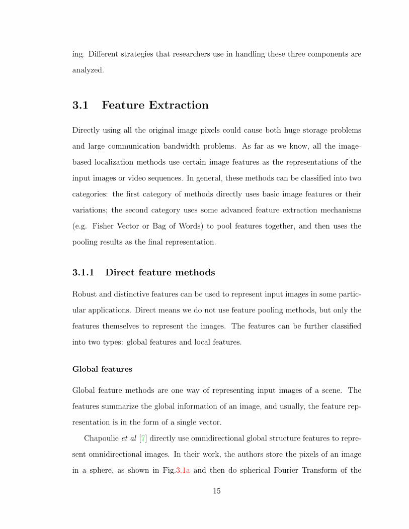
Chapoulie et al [7] directly use omnidirectional global structure features to repre-
sent omnidirectional images. In their work, the authors store the pixels of an image
in a sphere, as shown in Fig.3.1a and then do spherical Fourier Transform of the
15
(a) Spherical representation
(b) The first five spherical harmonicbands
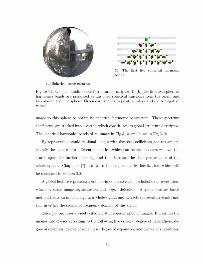
Figure 3.1: Global omnidirectional structural descriptor. In (b), the first five sphericalharmonics bands are presented as unsigned spherical functions from the origin andby color on the unit sphere. Green corresponds to positive values and red to negativevalues.
image to this sphere to obtain its spherical harmonic parameters. These spectrum
coefficients are stacked into a vector, which constitutes its global structure descriptor.
The spherical harmonics bands of an image in Fig.3.1a are shown in Fig.3.1b.
By representing omnidirectional images with discrete coefficients, the researchers
classify the images into different semantics, which can be used to narrow down the
search space for further indexing, and thus increase the time performance of the
whole system. Chapoulie [7] also called this step semantics localization, which will
be discussed in Section 3.2.
A global feature representation sometimes is also called an holistic representation,
which bypasses image segmentation and object detection. A global feature based
method treats an input image as a whole signal, and extracts representative informa-
tion in either the spatial or frequency domain of this signal.
Oliva [36] proposes a widely cited holistic representation of images. It classifies the
images into classes according to the following five criteria: degree of naturalness, de-
gree of openness, degree of roughness, degree of expansion, and degree of ruggedness.
16
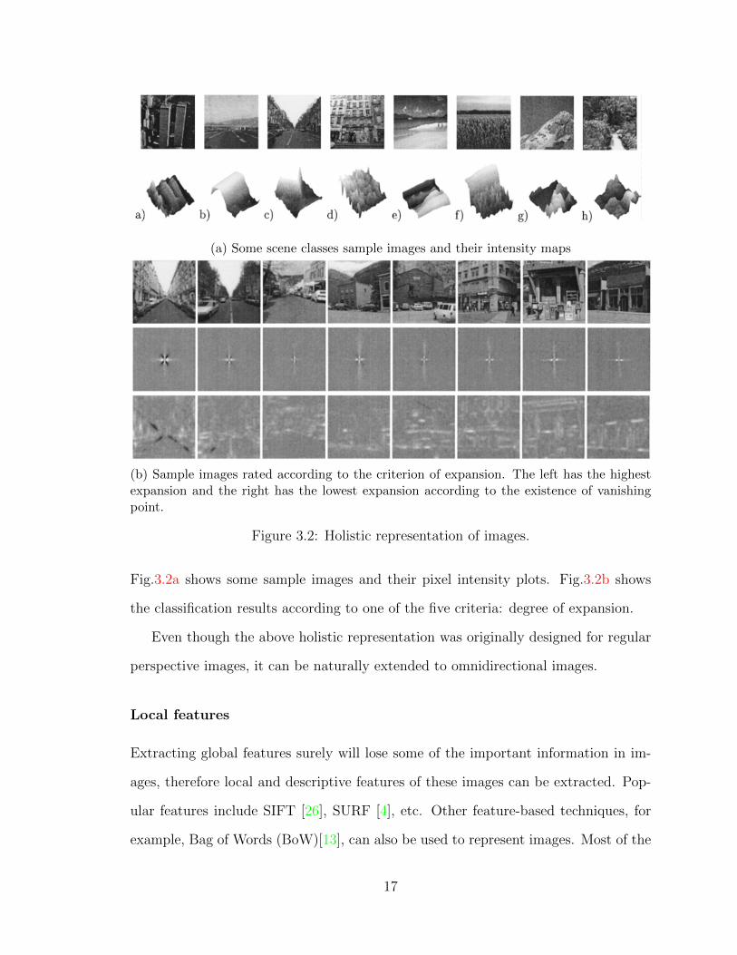
(a) Some scene classes sample images and their intensity maps
(b) Sample images rated according to the criterion of expansion. The left has the highestexpansion and the right has the lowest expansion according to the existence of vanishingpoint.
Figure 3.2: Holistic representation of images.
Fig.3.2a shows some sample images and their pixel intensity plots. Fig.3.2b shows
the classification results according to one of the five criteria: degree of expansion.
Even though the above holistic representation was originally designed for regular
perspective images, it can be naturally extended to omnidirectional images.
Local features
Extracting global features surely will lose some of the important information in im-
ages, therefore local and descriptive features of these images can be extracted. Pop-
ular features include SIFT [26], SURF [4], etc. Other feature-based techniques, for
example, Bag of Words (BoW)[13], can also be used to represent images. Most of the
17
above popular features are developed with regular images, but they could be readily
applied to omnidirectional images.
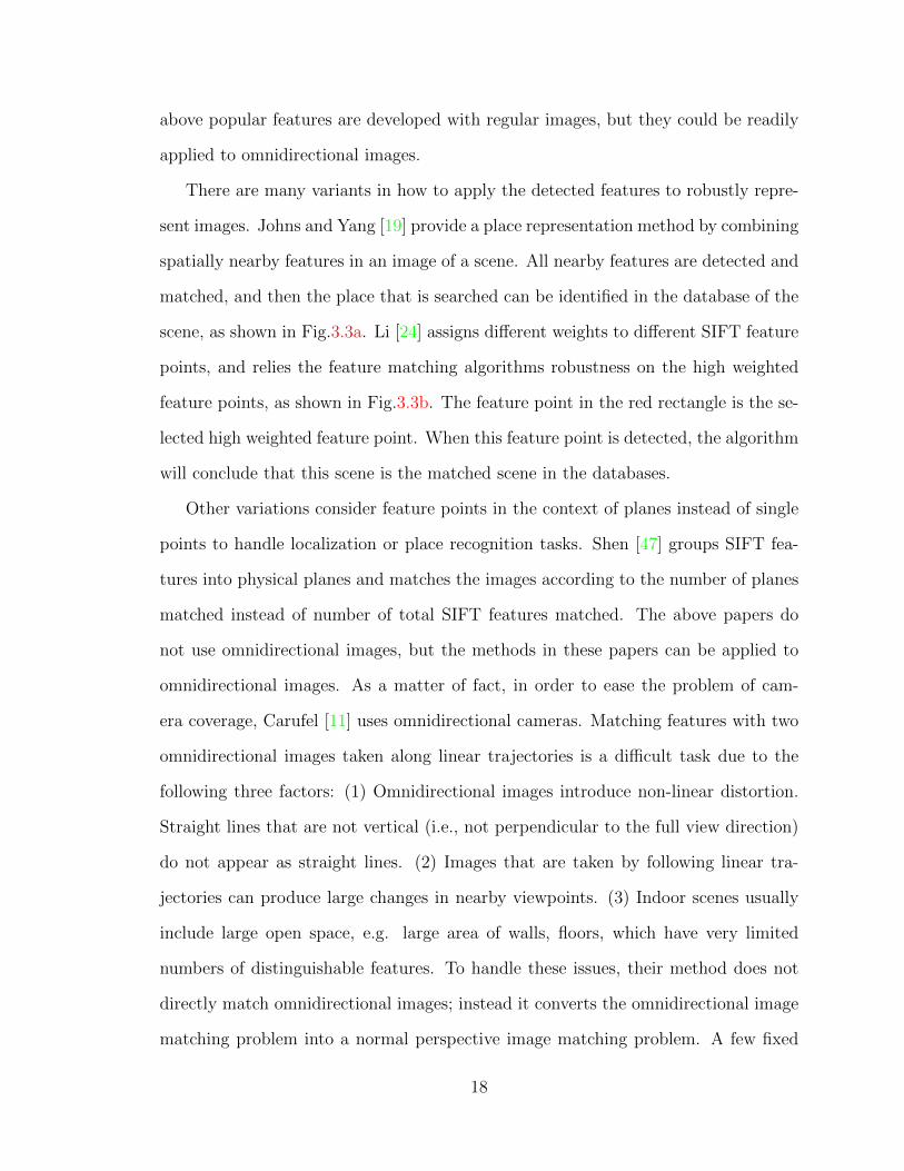
There are many variants in how to apply the detected features to robustly repre-
sent images. Johns and Yang [19] provide a place representation method by combining
spatially nearby features in an image of a scene. All nearby features are detected and
matched, and then the place that is searched can be identified in the database of the
scene, as shown in Fig.3.3a. Li [24] assigns different weights to different SIFT feature
points, and relies the feature matching algorithms robustness on the high weighted
feature points, as shown in Fig.3.3b. The feature point in the red rectangle is the se-
lected high weighted feature point. When this feature point is detected, the algorithm
will conclude that this scene is the matched scene in the databases.
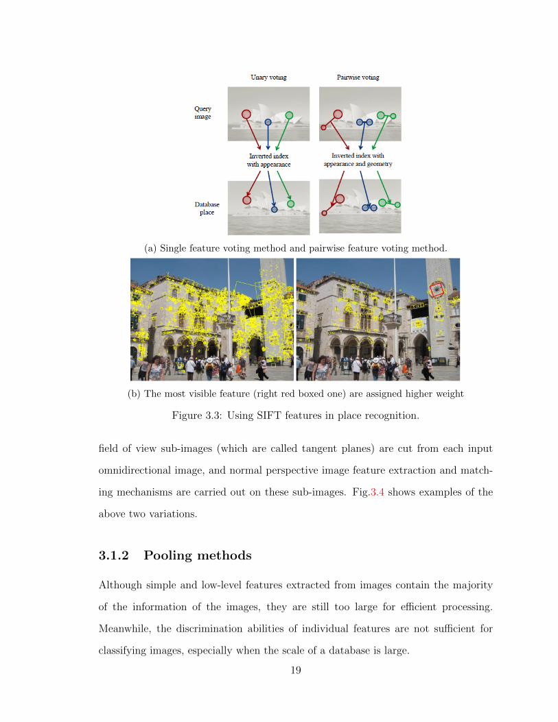
Other variations consider feature points in the context of planes instead of single
points to handle localization or place recognition tasks. Shen [47] groups SIFT fea-
tures into physical planes and matches the images according to the number of planes
matched instead of number of total SIFT features matched. The above papers do
not use omnidirectional images, but the methods in these papers can be applied to
omnidirectional images. As a matter of fact, in order to ease the problem of cam-
era coverage, Carufel [11] uses omnidirectional cameras. Matching features with two
omnidirectional images taken along linear trajectories is a difficult task due to the
following three factors: (1) Omnidirectional images introduce non-linear distortion.
Straight lines that are not vertical (i.e., not perpendicular to the full view direction)
do not appear as straight lines. (2) Images that are taken by following linear tra-
jectories can produce large changes in nearby viewpoints. (3) Indoor scenes usually
include large open space, e.g. large area of walls, floors, which have very limited
numbers of distinguishable features. To handle these issues, their method does not
directly match omnidirectional images; instead it converts the omnidirectional image
matching problem into a normal perspective image matching problem. A few fixed
18
(a) Single feature voting method and pairwise feature voting method.
(b) The most visible feature (right red boxed one) are assigned higher weight
Figure 3.3: Using SIFT features in place recognition.
field of view sub-images (which are called tangent planes) are cut from each input
omnidirectional image, and normal perspective image feature extraction and match-
ing mechanisms are carried out on these sub-images. Fig.3.4 shows examples of the
above two variations.
3.1.2 Pooling methods
Although simple and low-level features extracted from images contain the majority
of the information of the images, they are still too large for efficient processing.
Meanwhile, the discrimination abilities of individual features are not sufficient for
classifying images, especially when the scale of a database is large.
19
(a) Group features into planes(left) instead of treating them as separate individuals(right).
(b) Using tangent plane matching mechanism to increase the number of matches
Figure 3.4: Sample variant matching mechanisms.
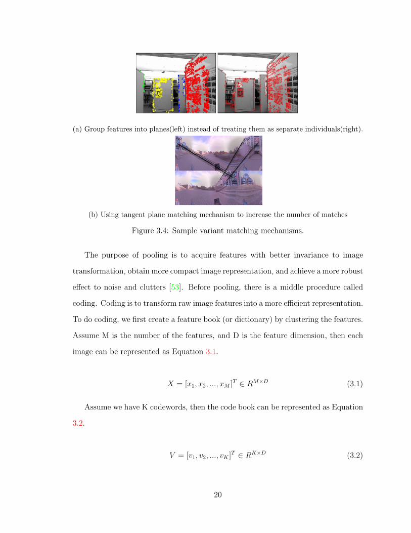
The purpose of pooling is to acquire features with better invariance to image
transformation, obtain more compact image representation, and achieve a more robust
effect to noise and clutters [53]. Before pooling, there is a middle procedure called
coding. Coding is to transform raw image features into a more efficient representation.
To do coding, we first create a feature book (or dictionary) by clustering the features.
Assume M is the number of the features, and D is the feature dimension, then each
image can be represented as Equation 3.1.
X = [x1, x2, ..., xM ]T ∈ RM×D (3.1)
Assume we have K codewords, then the code book can be represented as Equation
3.2.
V = [v1, v2, ..., vK ]T ∈ RK×D (3.2)
20
By quantizing each feature descriptor into one or several code words, we will have
a matrix A ∈ RM×K . Each element in this matrix is either 1 or 0, indicating whether a
descriptor belongs to a code-word or not. Its element can be represented as Equation
3.3.
αi,j =
1, if j = argkmin||xi − vk||22
0, otherwise
(3.3)
After we get this matrix, we have two pooling strategies. The first strategy is
average pooling, which is to convert the matrix into a K dimensional vector, where
K is the size of the codebook, and the i-th element in this K dimensional vector is
the average of i-th column. The second strategy is called max pooling, which uses
the maximal value of each column to form each element in the K dimensional vector
instead of using its average value.
A pooling method can be used to localize an image in a database. For example,
Altwaijry [1] uses pooling methods and combines the Pyramid Histogram Of visual
Words (PHOW) feature [6] and the SIFT features to implement a place recognition
system.
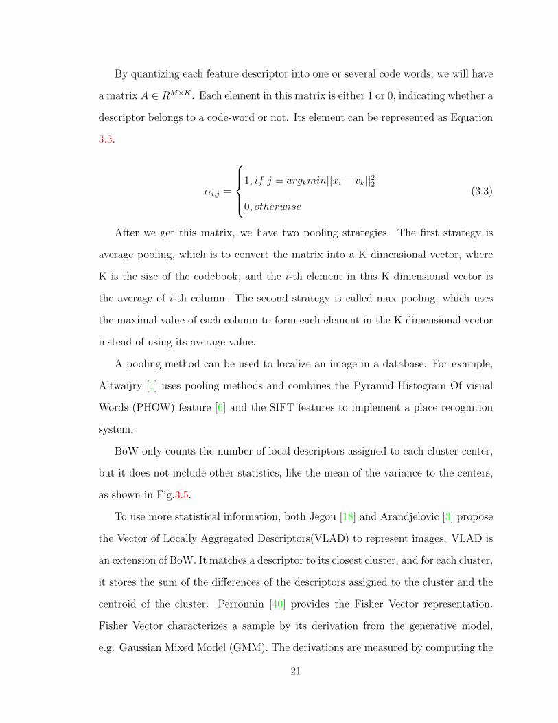
BoW only counts the number of local descriptors assigned to each cluster center,
but it does not include other statistics, like the mean of the variance to the centers,
as shown in Fig.3.5.
To use more statistical information, both Jegou [18] and Arandjelovic [3] propose
the Vector of Locally Aggregated Descriptors(VLAD) to represent images. VLAD is
an extension of BoW. It matches a descriptor to its closest cluster, and for each cluster,
it stores the sum of the differences of the descriptors assigned to the cluster and the
centroid of the cluster. Perronnin [40] provides the Fisher Vector representation.
Fisher Vector characterizes a sample by its derivation from the generative model,
e.g. Gaussian Mixed Model (GMM). The derivations are measured by computing the
21
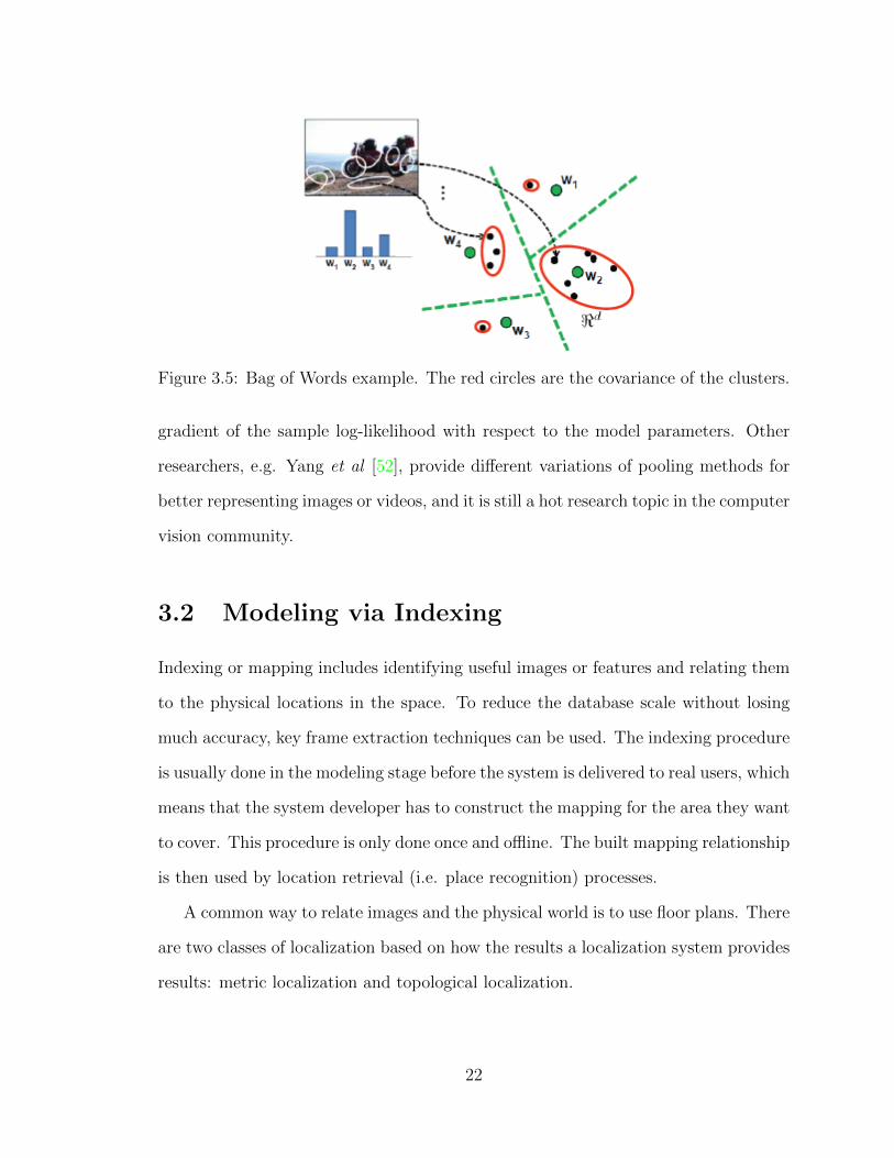
Figure 3.5: Bag of Words example. The red circles are the covariance of the clusters.
gradient of the sample log-likelihood with respect to the model parameters. Other
researchers, e.g. Yang et al [52], provide different variations of pooling methods for
better representing images or videos, and it is still a hot research topic in the computer
vision community.
3.2 Modeling via Indexing
Indexing or mapping includes identifying useful images or features and relating them
to the physical locations in the space. To reduce the database scale without losing
much accuracy, key frame extraction techniques can be used. The indexing procedure
is usually done in the modeling stage before the system is delivered to real users, which
means that the system developer has to construct the mapping for the area they want
to cover. This procedure is only done once and offline. The built mapping relationship
is then used by location retrieval (i.e. place recognition) processes.
A common way to relate images and the physical world is to use floor plans. There
are two classes of localization based on how the results a localization system provides
results: metric localization and topological localization.
22
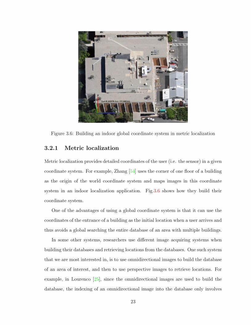
Figure 3.6: Building an indoor global coordinate system in metric localization
3.2.1 Metric localization
Metric localization provides detailed coordinates of the user (i.e. the sensor) in a given
coordinate system. For example, Zhang [54] uses the corner of one floor of a building
as the origin of the world coordinate system and maps images in this coordinate
system in an indoor localization application. Fig.3.6 shows how they build their
coordinate system.
One of the advantages of using a global coordinate system is that it can use the
coordinates of the entrance of a building as the initial location when a user arrives and
thus avoids a global searching the entire database of an area with multiple buildings.
In some other systems, researchers use different image acquiring systems when
building their databases and retrieving locations from the databases. One such system
that we are most interested in, is to use omnidirectional images to build the database
of an area of interest, and then to use perspective images to retrieve locations. For
example, in Lourenco [25], since the omnidirectional images are used to build the
database, the indexing of an omnidirectional image into the database only involves
23
Figure 3.7: Mapping omnidirectional images with 3D physical world.
the determination of the omnidirectional cameras location when capturing that image.
Fig.3.7 shows how it works. The authors take advantage of the omnidirectional images
to perform a complete coverage of the environment, and retrieve the location of a
query image taken from a conventional camera, e.g. a cell phone image taken from a
person who wants to retrieve his location. SIFT features of both the omnidirectional
image and the perspective image are extracted, and a variation of BoW called visual
phrases is used to match the standard camera image and the omnidirectional image
database in the indexing stage.
In modeling a scene with omnidirectional images, some other researchers
Chapoulie [7] directly labeled the positions of omnidirectional images into the
floor plan, as shown in Fig.3.8. The middle of Fig.3.8 is a floor plan . The black
curve within the floor plan is a path of the omnidirectional camera. Omnidirectional
images are captured along this path, and the images that surround the floor plan are
sample omnidirectional images.
24
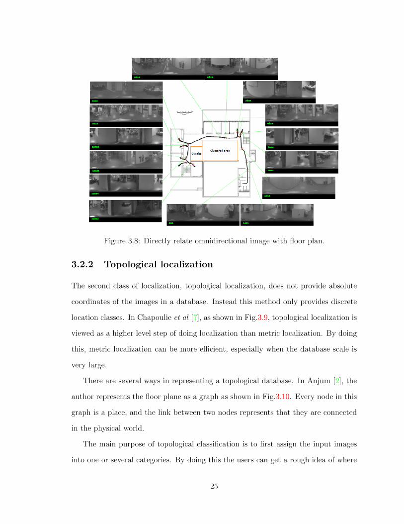
Figure 3.8: Directly relate omnidirectional image with floor plan.
3.2.2 Topological localization
The second class of localization, topological localization, does not provide absolute
coordinates of the images in a database. Instead this method only provides discrete
location classes. In Chapoulie et al [7], as shown in Fig.3.9, topological localization is
viewed as a higher level step of doing localization than metric localization. By doing
this, metric localization can be more efficient, especially when the database scale is
very large.
There are several ways in representing a topological database. In Anjum [2], the
author represents the floor plane as a graph as shown in Fig.3.10. Every node in this
graph is a place, and the link between two nodes represents that they are connected
in the physical world.
The main purpose of topological classification is to first assign the input images
into one or several categories. By doing this the users can get a rough idea of where
25
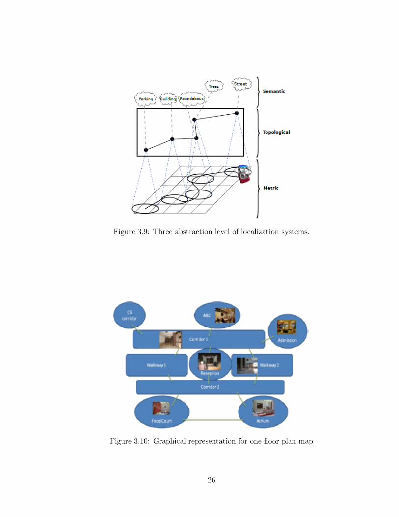
Figure 3.9: Three abstraction level of localization systems.
Figure 3.10: Graphical representation for one floor plan map
26
he/she is; and also, this step could be an initial step to achieve a refine and metric
localization result.
3.3 Localization via Retrieval
The 2D retrieval process includes the following steps: (1) capture one or more new
images; (2) search them against the database of a scene; (3) find the most likely
matched ones; and (4) finally output the localization results under certain matching
criteria.
According to the steps involved in getting the final localization results, the retrieval
can be divided into two classes: one step methods and multi-step methods. While
a one-step method obtains final localization results directly, multi-step methods are
typically used with the large scale databases, and typically a coarse-to-fine strategy
is applied to deal with the scale problem or reduce the search space and accelerate
the query time.
3.3.1 One-step methods
With a small database, the retrieval process can directly output localization results.
According to the purposes of the localization, i.e., whether only topological classes
are needed, or the exact coordinates of the camera capturing the input images is
required in a given coordinate system, the query procedure can be one of the two
classes: topological retrieval or metric retrieval.
Topological retrieval
A topological retrieval problem in essence is a discrete place recognition problem.
The main idea is to classify an input image into one or more place class candidates,
which have been designed and determined in the database building stage. After the
27
topological retrieval is finished, metric retrieval can also be carried out within the
selected class to determine a refined localization result.
A pyramidal matching strategy is used in Murillo [31] to implement topological
localization. Fig.3.11 shows a sample pyramidal matching result. The method is
suitable when the dimension of the feature descriptor in use is low. For example,
in Fig.3.11, the descriptor dimension size is 2. As studied in [31], when descriptor
size increases, such as the SIFT descriptor with 128 dimension, this method does not
work well. Pyramidal means every elements of each feature’s vector are classified
into a multi-dimensional histogram. Every dimension of the histogram records the
distribution of values within the corresponding vector element. Histogram bin size
changes from large scale to small scale.
For example, assume that we have an image I, and there are M features detected
in the image I. Every feature is described with a vector with a dimension N. The
dimension of the vector equals the dimension of the histogram. So a N-dimensional
histogram will be created. (Note that the histogram here is a high dimensional
histogram, which is different from the single dimension histogram in classical image
processing). In the specific example shown in Fig.3.11, M = 2, and N = 2 also. The
bins in this example are no longer line segments, but square boxes, as colored in
Fig.3.11. Number of matches is defined as the number of features fallen into the same
bin.
The N bins of the N-dimensional histogram are then quantized with different unit
sizes from coarse to fine. In Fig.3.11, the bin sizes are 4, 2 and 1. For every level, a
comparison result between two images is calculated according to a similarity distance
function, and the final result is a combination of the results from all pyramidal levels.
Support Vector Machine(SVM) is another widely-used topological retrieval
method. For every topological class, a model is pre-built and utilized as the compar-
ison template. A new input image is compared with these models and is classified
28
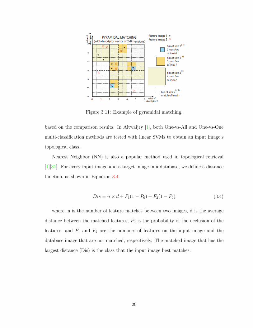
Figure 3.11: Example of pyramidal matching.
based on the comparison results. In Altwaijry [1], both One-vs-All and One-vs-One
multi-classification methods are tested with linear SVMs to obtain an input image’s
topological class.
Nearest Neighbor (NN) is also a popular method used in topological retrieval
[1][31]. For every input image and a target image in a database, we define a distance
function, as shown in Equation 3.4.
Dis = n× d+ F1(1− P0) + F2(1− P0) (3.4)
where, n is the number of feature matches between two images, d is the average
distance between the matched features, P0 is the probability of the occlusion of the
features, and F1 and F2 are the numbers of features on the input image and the
database image that are not matched, respectively. The matched image that has the
largest distance (Dis) is the class that the input image best matches.
29
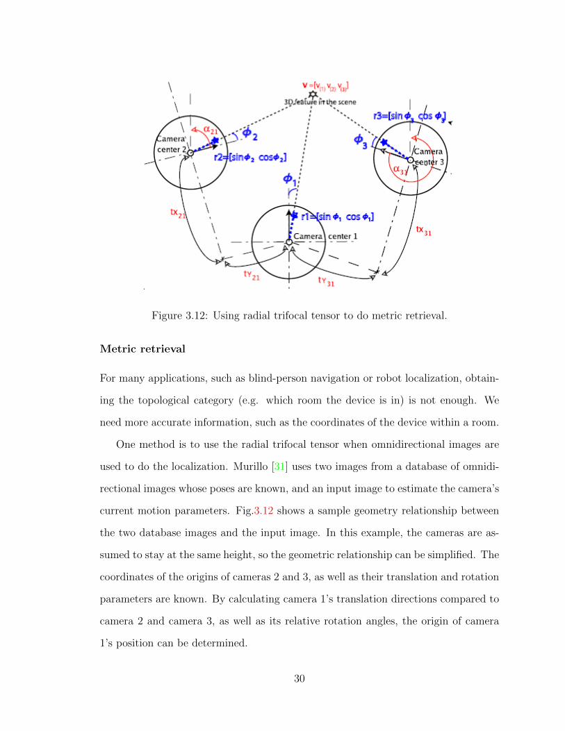
Figure 3.12: Using radial trifocal tensor to do metric retrieval.
Metric retrieval
For many applications, such as blind-person navigation or robot localization, obtain-
ing the topological category (e.g. which room the device is in) is not enough. We
need more accurate information, such as the coordinates of the device within a room.
One method is to use the radial trifocal tensor when omnidirectional images are
used to do the localization. Murillo [31] uses two images from a database of omnidi-
rectional images whose poses are known, and an input image to estimate the camera’s
current motion parameters. Fig.3.12 shows a sample geometry relationship between
the two database images and the input image. In this example, the cameras are as-
sumed to stay at the same height, so the geometric relationship can be simplified. The
coordinates of the origins of cameras 2 and 3, as well as their translation and rotation
parameters are known. By calculating camera 1’s translation directions compared to
camera 2 and camera 3, as well as its relative rotation angles, the origin of camera
1’s position can be determined.
30
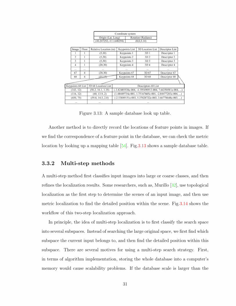
Figure 3.13: A sample database look up table.
Another method is to directly record the locations of feature points in images. If
we find the correspondence of a feature point in the database, we can check the metric
location by looking up a mapping table [54]. Fig.3.13 shows a sample database table.
3.3.2 Multi-step methods
A multi-step method first classifies input images into large or coarse classes, and then
refines the localization results. Some researchers, such as, Murillo [32], use topological
localization as the first step to determine the scenes of an input image, and then use
metric localization to find the detailed position within the scene. Fig.3.14 shows the
workflow of this two-step localization approach.
In principle, the idea of multi-step localization is to first classify the search space
into several subspaces. Instead of searching the large original space, we first find which
subspace the current input belongs to, and then find the detailed position within this
subspace. There are several motives for using a multi-step search strategy. First,
in terms of algorithm implementation, storing the whole database into a computer’s
memory would cause scalability problems. If the database scale is larger than the
31
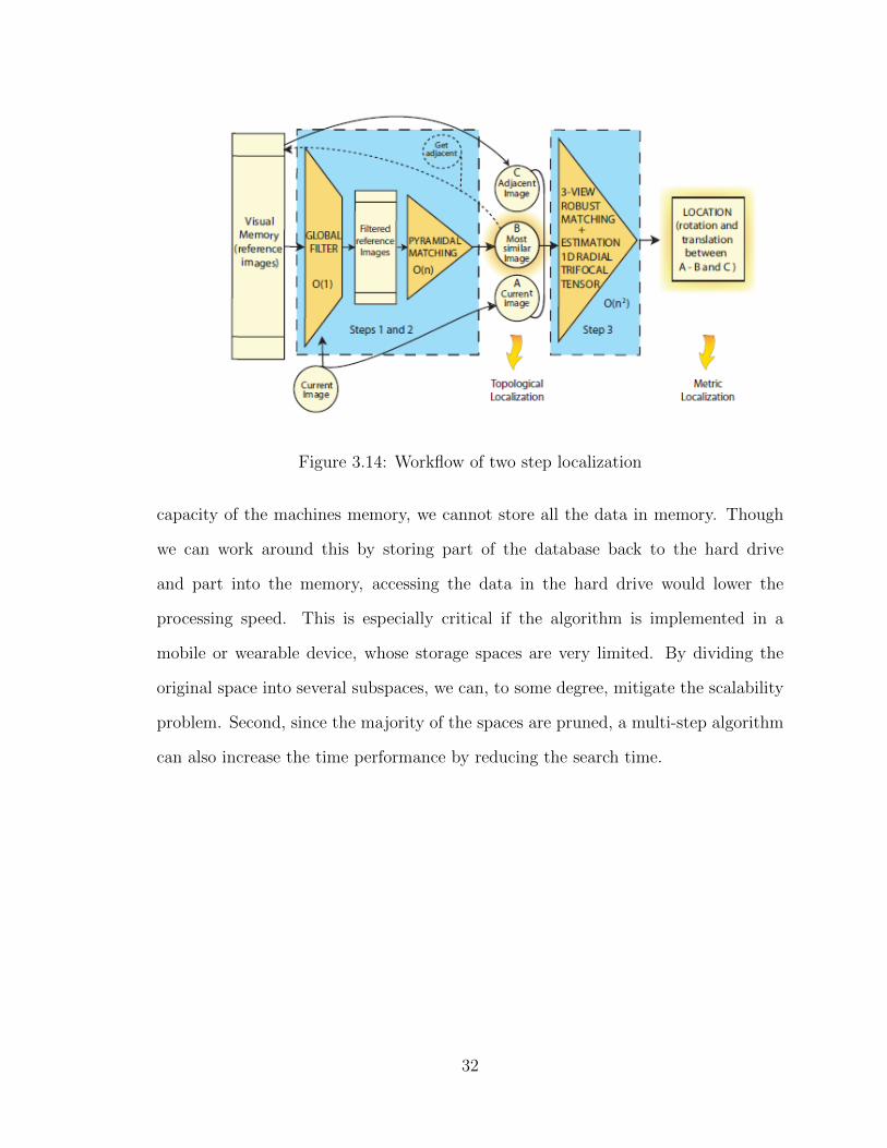
Figure 3.14: Workflow of two step localization
capacity of the machines memory, we cannot store all the data in memory. Though
we can work around this by storing part of the database back to the hard drive
and part into the memory, accessing the data in the hard drive would lower the
processing speed. This is especially critical if the algorithm is implemented in a
mobile or wearable device, whose storage spaces are very limited. By dividing the
original space into several subspaces, we can, to some degree, mitigate the scalability
problem. Second, since the majority of the spaces are pruned, a multi-step algorithm
can also increase the time performance by reducing the search time.
32
Chapter 4
3D Model-based Approaches
Real physical space is three dimensional; thus, it is natural to sense the world with
3D sensors or 3D reconstruction and then build 3D models to achieve visual localiza-
tion. There are quite a few methods to obtain the third dimension (depth) data. In
this review, we only discuss two major method types: Structure from Motion (SfM)
methods and direct 3D sensing methods.
4.1 SfM-based localization
SfM is the process of estimating three-dimensional structure from two-dimensional
image sequences. SfM can also be used to estimate the movement of a camera. In
this section, we do not focus on how to generate a 3D point cloud with SfM; instead,
we focus on how to use the 3D points generated by SfM in order to localize a new
input image in the database.
Depending on the sources of the 2D images, SfM based localization approaches
can be classified into two categories: crowdsourced images and user-captured images
based localization.
33
4.1.1 SfM localization with crowdsourced images
Given the emergence of digital images/videos of city streets, and the rapid develop-
ment of SfM techniques and software packages, using crowdsourced image—usually
from the Web—and SfM-generated 3D point clouds to localize a new input image is
attracting more and more attention [43][44][45][46][16].
Many SfM tools and software packages have been developed to generate 3D point
clouds. Some of them are commercial while others are open sourced. The propri-
etary ones include Microsoft’s Photosynth 1, Autodesk’s 123D Catch 2, and 3DFlow’s
Zephyr 3. The open source packages include Insight 3D 4, and SFMToolkit 5. Others
are from research groups, which include Bundler [35] by Noah Snavely, VisualSFM
[50] by Changchang Wu, and OpenSLAM [41] by Kuemmerle et al. The popularity
of SfM packages makes the task of generating a 3D point cloud of a scene easier and
greatly facilitates SfM-based image localization research.
There are many advantages in using Web-based crowdsourced images/videos.
First, the amount of data is huge, in particular, streets and cities data sets of place
of common interests generated by tourists. Second, the cameras positions are widely
distributed over a large area; instead of a few fixed paths if taken by a few researchers,
since the images are captured by different people for different purposes. Third, as
the images are taken in different seasons, under different lighting conditions, and
with different cameras, the databases more representative for successful localization.
Although the number of omnidirectional images is small compared to normal perspec-
tive images, the principle of building omnidirectional databases for omnidirectional
1http://photosynth.net/2http://www.123dapp.com/catch3http://www.3dflow.net/3df-zephyr-pro-3d-models-from-photos/4http://insight3d.sourceforge.net/5https://github.com/dddExperiments/SFMToolkit
34

image based indoor localization is the same. There are quite a number of sites that
have omnidirectional images 67.
Since the cameras taking the images are not calibrated, we cannot determine
the final scale of the 3D model built by SfM from images alone. However, it is
still meaningful to localize input images within these 3D models. Much of the work
discussed below concerns normal perspective images; however, they can extend to
omnidirectional images as well.
We denote the points in the 2D images as features, and a point in the 3D points
in the SfM model as points, which may be associated with many features . A general
localization problem can be stated as: given an input image, find which points in
the model are matched with this image. If corresponding points are found, we can
use the perspective N-points (pNp) algorithm to determine the camera location and
orientation, i.e., the camera pose. A SfM model is usually huge, which may includes
millions of points; so, a key issues is how to match the features with the points. We
can category two matching methods: 2D-to-3D matching and 3D-to-2D matching.
2D to 3D matching
Given an 2D input image, one natural method to find its corresponding 3D points
within the SfM model is to first find its matching images in the database, then find
the related 3D points. However, this is not always necessary: we can directly find
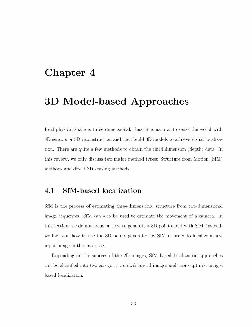
the 2D image’s corresponding 3D points in the database [43]. Fig.4.1 shows an query
image sample and part of the 3D database.
The main idea of 2D-to-3D matching is to first cluster the features of many trained
images into the feature space, and then construct the visual words (codebook). Loca-
tions in the 3D model are associated with a number of clusters of visual words. The
visual words can be stored in a linear data structure or in a K-d tree structure. When
6http://www.360cities.net7http://panoramas.dk
35
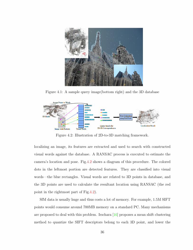
Figure 4.1: A sample query image(bottom right) and the 3D database
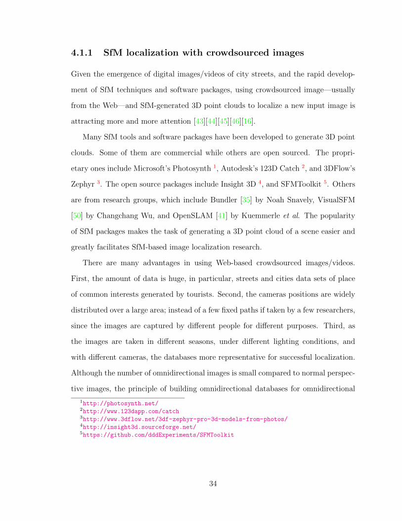
Figure 4.2: Illustration of 2D-to-3D matching framework.
localizing an image, its features are extracted and used to search with constructed
visual words against the database. A RANSAC process is executed to estimate the
camera’s location and pose. Fig.4.2 shows a diagram of this procedure. The colored
dots in the leftmost portion are detected features. They are classified into visual
words—the blue rectangles. Visual words are related to 3D points in database, and
the 3D points are used to calculate the resultant location using RANSAC (the red
point in the rightmost part of Fig.4.2).
SfM data is usually huge and thus costs a lot of memory. For example, 1.5M SIFT
points would consume around 700MB memory on a standard PC. Many mechanisms
are proposed to deal with this problem. Irschara [16] proposes a mean shift clustering
method to quantize the SIFT descriptors belong to each 3D point, and lower the
36
Figure 4.3: An example of synthetic views (red ones)
memory footprint of the 3D representation. Sattler [45] uses only a subset of the
3D model by only selecting the 3D points near a cluster center to lower the memory
usage while maintaining the same level of performance.
Similar to the 2D generative method [17], some modification of the 3D model can
be made to further improve the performance both in terms of accuracy and speed.
Irschara [16] uses generated synthetic views of the original SfM models to reduce
the size of the data, and at the same time improve the robustness of the algorithm.
Fig.4.3 shows an example of generated synthetic views from 3D models.
3D-to-2D matching
Li [24] and Sattler [44] improve the efficiency of feature matching and searching
procedures by changing the direction of the search. Instead of using 2D features
to query a 3D point cloud database, they reverse the procedure by searching 2D
features with 3D points. Fig.4.4 shows a diagram of their 3D-to-2D method. First,
the points in the model are offline assigned to visual words. When a new input image
arrives, its SIFT features are used to index it into the visual word vocabulary, and
37
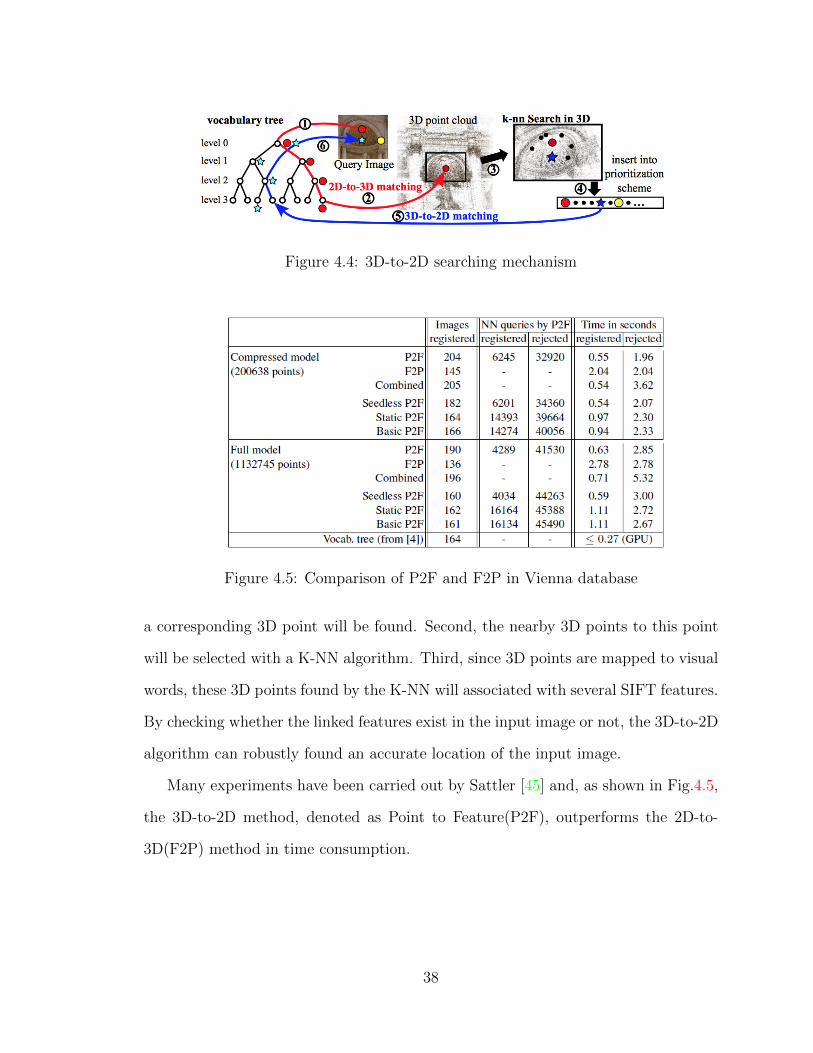
Figure 4.4: 3D-to-2D searching mechanism
Figure 4.5: Comparison of P2F and F2P in Vienna database
a corresponding 3D point will be found. Second, the nearby 3D points to this point
will be selected with a K-NN algorithm. Third, since 3D points are mapped to visual
words, these 3D points found by the K-NN will associated with several SIFT features.
By checking whether the linked features exist in the input image or not, the 3D-to-2D
algorithm can robustly found an accurate location of the input image.
Many experiments have been carried out by Sattler [45] and, as shown in Fig.4.5,
the 3D-to-2D method, denoted as Point to Feature(P2F), outperforms the 2D-to-
3D(F2P) method in time consumption.
38
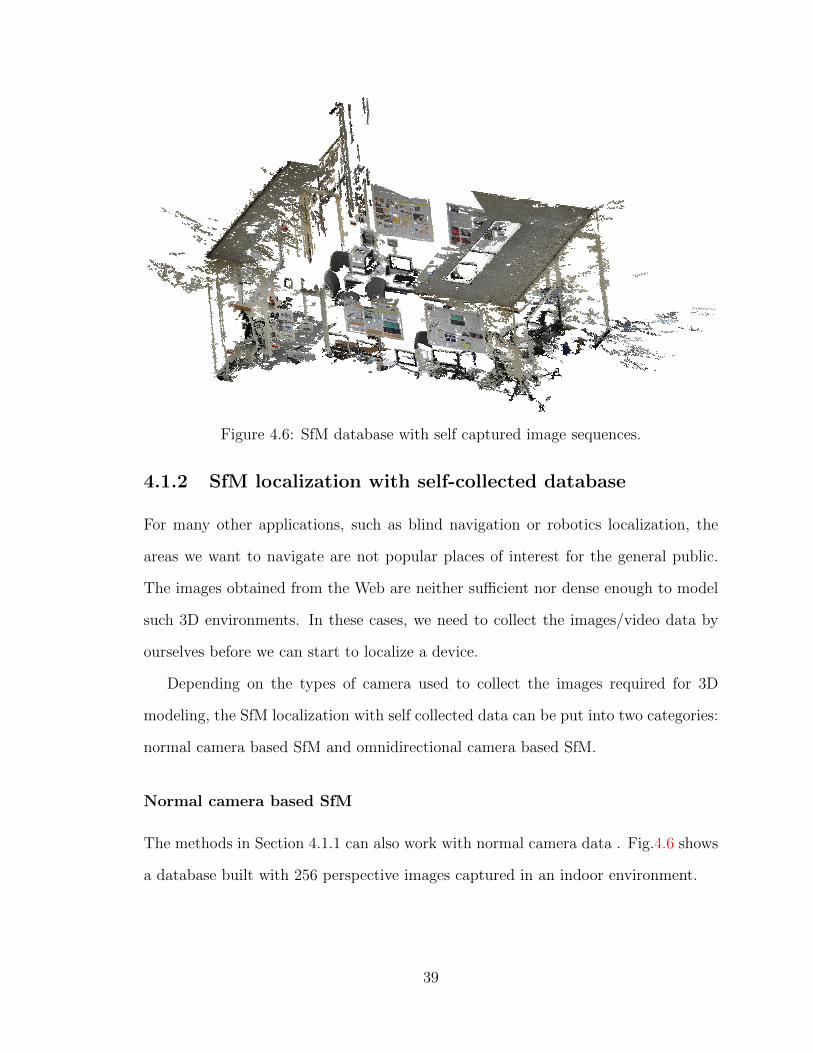
Figure 4.6: SfM database with self captured image sequences.
4.1.2 SfM localization with self-collected database
For many other applications, such as blind navigation or robotics localization, the
areas we want to navigate are not popular places of interest for the general public.
The images obtained from the Web are neither sufficient nor dense enough to model
such 3D environments. In these cases, we need to collect the images/video data by
ourselves before we can start to localize a device.
Depending on the types of camera used to collect the images required for 3D
modeling, the SfM localization with self collected data can be put into two categories:
normal camera based SfM and omnidirectional camera based SfM.
Normal camera based SfM
The methods in Section 4.1.1 can also work with normal camera data . Fig.4.6 shows
a database built with 256 perspective images captured in an indoor environment.
39
Omnidirectional camera based SfM
Several groups [28] [20] [37][21] use omnidirectional images to build their 3D models.
The advantages of using omnidirectional images include:
(1) They have a wide field of view, and thus can reduce the number of images
needed for constructing the same scene.
(2) It will lead to a fast and efficient data acquisition procedure since at each
location all the viewing directions are covered.
The disadvantages of using omnidirectional images are in image distortion and low
image resolution. Due to large distortion compared to perspective imaging processes,
it is harder to find correspondences among images. Fig.4.7 shows some sample 3D
models constructed with omnidirectional images.
4.1.3 The scale problem
The SfM model only represents the physical 3D space up to a scale. To solve this
scale problem, we need extra knowledge about the environment.
Kume resolves the scale problem by using odometry [22]. Another method [54]
to solve this problem is to relate a 2D image feature with the 3D physical world
by manually labeling it. In Zhang et al [54], the authors manually relate the SIFT
feature with a 3D point. The scale of the model can then be determined by using
known 3D points. Fig.4.8 shows a labeling result of feature points to corresponding
3D points.
4.2 3D sensor based methods
The 3D environment information can also be obtained directly with portable and
real-time 3D sensors, such as Microsoft’s Kinect, ASUS’s Xtion, etc. This 3D data
can be used to localize the device.
40
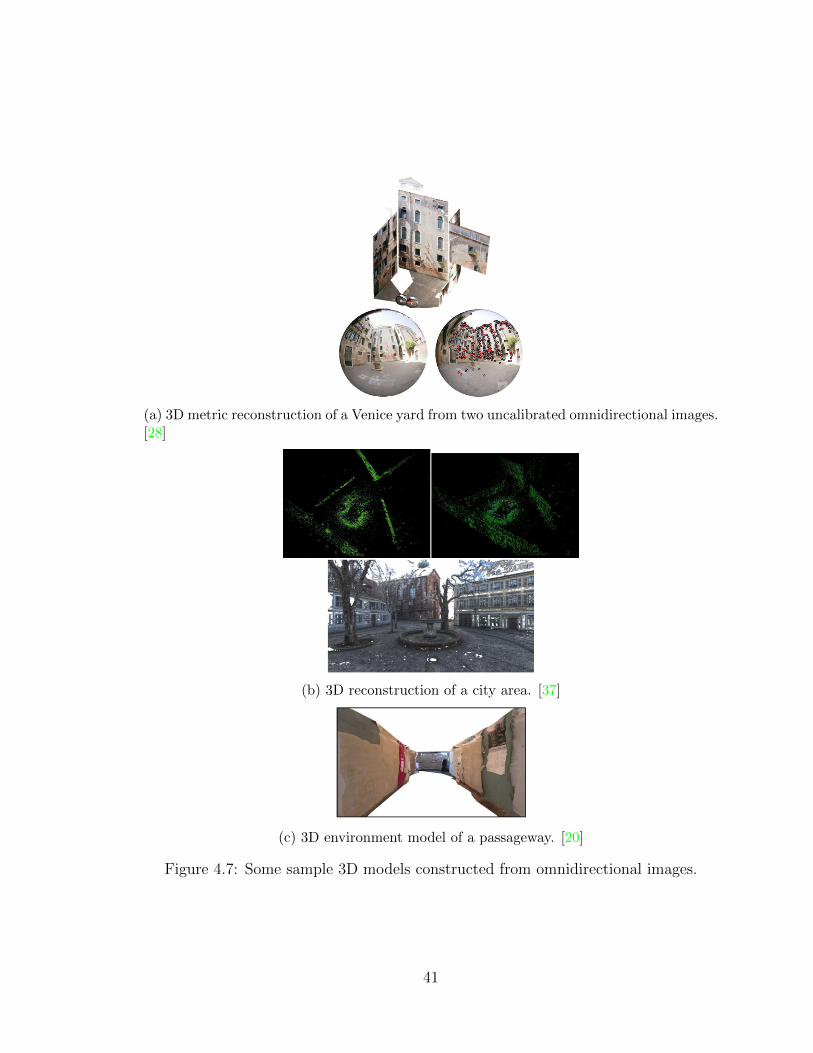
(a) 3D metric reconstruction of a Venice yard from two uncalibrated omnidirectional images.[28]
(b) 3D reconstruction of a city area. [37]
(c) 3D environment model of a passageway. [20]
Figure 4.7: Some sample 3D models constructed from omnidirectional images.
41
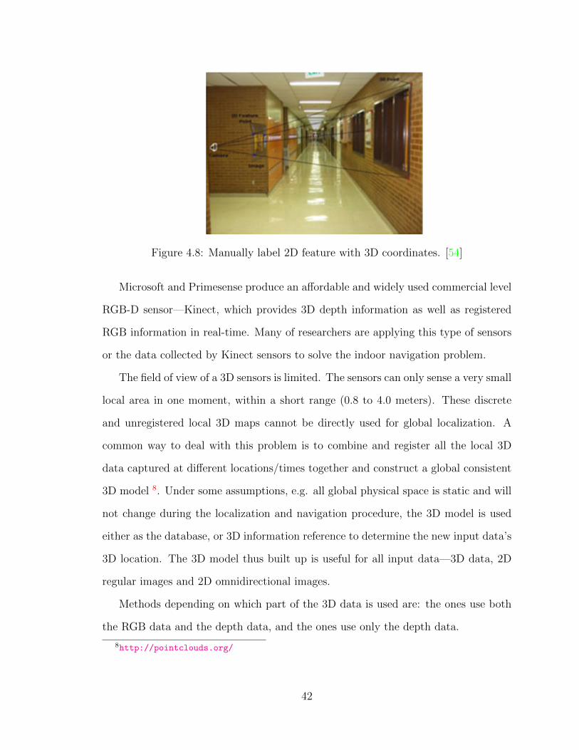
Figure 4.8: Manually label 2D feature with 3D coordinates. [54]
Microsoft and Primesense produce an affordable and widely used commercial level
RGB-D sensor—Kinect, which provides 3D depth information as well as registered
RGB information in real-time. Many of researchers are applying this type of sensors
or the data collected by Kinect sensors to solve the indoor navigation problem.
The field of view of a 3D sensors is limited. The sensors can only sense a very small
local area in one moment, within a short range (0.8 to 4.0 meters). These discrete
and unregistered local 3D maps cannot be directly used for global localization. A
common way to deal with this problem is to combine and register all the local 3D
data captured at different locations/times together and construct a global consistent
3D model 8. Under some assumptions, e.g. all global physical space is static and will
not change during the localization and navigation procedure, the 3D model is used
either as the database, or 3D information reference to determine the new input data’s
3D location. The 3D model thus built up is useful for all input data—3D data, 2D
regular images and 2D omnidirectional images.
Methods depending on which part of the 3D data is used are: the ones use both
the RGB data and the depth data, and the ones use only the depth data.
8http://pointclouds.org/
42
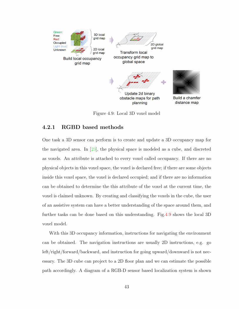
Figure 4.9: Local 3D voxel model
4.2.1 RGBD based methods
One task a 3D sensor can perform is to create and update a 3D occupancy map for
the navigated area. In [23], the physical space is modeled as a cube, and discreted
as voxels. An attribute is attached to every voxel called occupancy. If there are no
physical objects in this voxel space, the voxel is declared free; if there are some objects
inside this voxel space, the voxel is declared occupied; and if there are no information
can be obtained to determine the this attribute of the voxel at the current time, the
voxel is claimed unknown. By creating and classifying the voxels in the cube, the user
of an assistive system can have a better understanding of the space around them, and
further tasks can be done based on this understanding. Fig.4.9 shows the local 3D
voxel model.
With this 3D occupancy information, instructions for navigating the environment
can be obtained. The navigation instructions are usually 2D instructions, e.g. go
left/right/forward/backward, and instruction for going upward/downward is not nec-
essary. The 3D cube can project to a 2D floor plan and we can estimate the possible
path accordingly. A diagram of a RGB-D sensor based localization system is shown
43
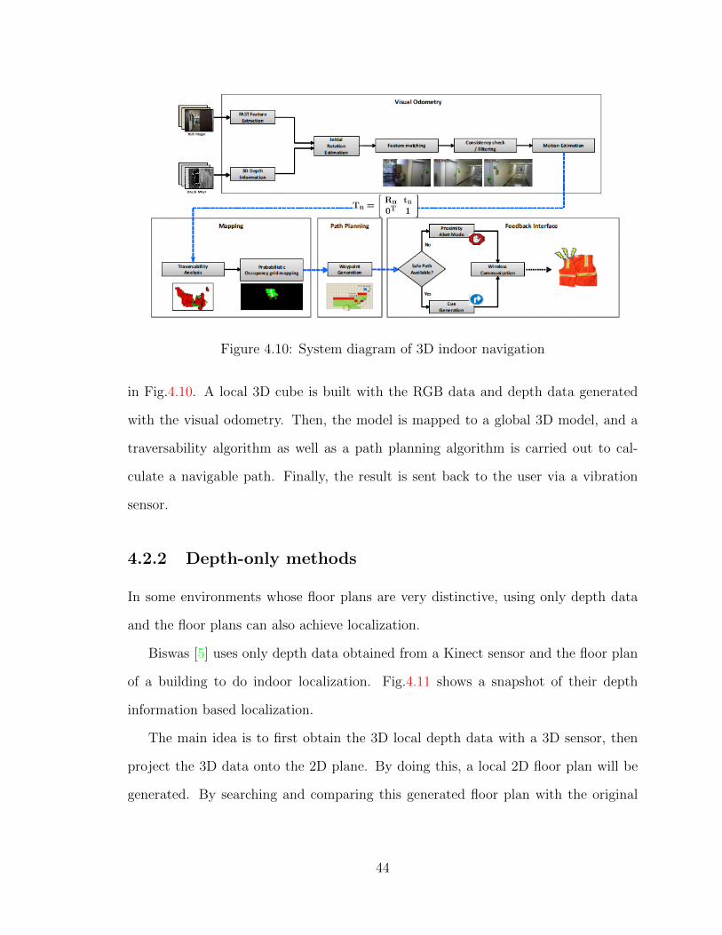
Figure 4.10: System diagram of 3D indoor navigation
in Fig.4.10. A local 3D cube is built with the RGB data and depth data generated
with the visual odometry. Then, the model is mapped to a global 3D model, and a
traversability algorithm as well as a path planning algorithm is carried out to cal-
culate a navigable path. Finally, the result is sent back to the user via a vibration
sensor.
4.2.2 Depth-only methods
In some environments whose floor plans are very distinctive, using only depth data
and the floor plans can also achieve localization.
Biswas [5] uses only depth data obtained from a Kinect sensor and the floor plan
of a building to do indoor localization. Fig.4.11 shows a snapshot of their depth
information based localization.
The main idea is to first obtain the 3D local depth data with a 3D sensor, then
project the 3D data onto the 2D plane. By doing this, a local 2D floor plan will be
generated. By searching and comparing this generated floor plan with the original
44
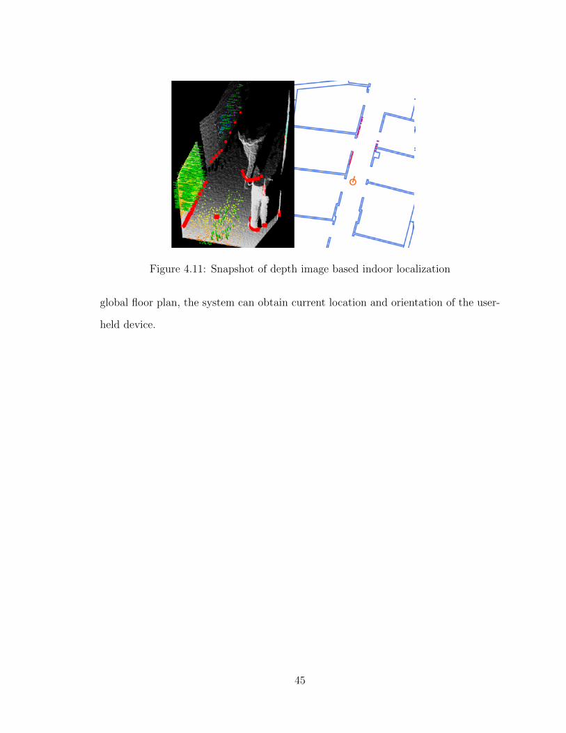
Figure 4.11: Snapshot of depth image based indoor localization
global floor plan, the system can obtain current location and orientation of the user-
held device.
45
Chapter 5
Challenging Issues and Emerging
Solutions
Vision-based indoor localization has many challenges in different steps of the system
workflow, starting from using sensors to obtain raw data to finally evaluating the
system performance. We will present three major challenges in sensing, computation
and system levels, followed by two emerging techniques as possible solutions: mobile
platforms and GPU accelerating with cloud computing.
5.1 Challenging Issues
There are several challenges discussed here. In Section 5.1.1, we will discuss system
accuracy issues and the sensor capacity. In Section 5.1.2, we will discuss computa-
tional cost and real time performance issue in building a localization system. In 5.1.3,
we will discuss the evaluation of working systems.
46
5.1.1 System accuracy standard and sensor capacity
Indoor localization accuracy standards are not clearly defined by researchers. An
industrial company, SPREO 1, uses two meter as their tolerance limit. With a two
meter accuracy, a user can differentiate the doors of two nearby stores or offices,
detect the floors on which the user is using, or find a car in a parking lot.
For systems which use up-to-scale 3D models—e.g. SfM point cloud models in
[43][16]—the accuracy relies on both the retrieval accuracy within the model, and the
3D models’ accuracy relates to the physical world.
2D image search based methods—e.g. Cummins [10]—use a precision-recall curve
to measure the localization performance. To see whether a search algorithm has found
the most relevant data, and if it has missed some important items, researchers use
search precision and recall parameters to evaluate the results. Assume that all the
records in a database are either relevant or irrelevant to a given search keyword. The
precision is the number of relevant records retrieved with respect to the total num-
ber of irrelevant and relevant records retrieved together. The recall is the number of
relevant records retrieved with respect to the total number of relevant records in the
database. In Cummins [10], the system is used to complement a metric SLAM algo-
rithm; and, as an incorrect loop closure could cause unrecoverable mapping failure;
the authors set the precision threshold to 100%.
One factor that affects final localization accuracy is the capacity and accuracy of
the sensors used. The capacity and accuracy of popular sensors used in localization
applications are reviewed and discussed. These sensors include cameras in smart-
phones and wearable devices, omnidirectional lens/mirrors, 3D sensors, etc.
Cameras are ubiquitous in smart-phones and wearable devices. The capacity and
accuracy of the camera has a significant influence on system performance. Table 5.1.1
lists the major parameters of popular cameras on devices.
1http://spreo.co/
47
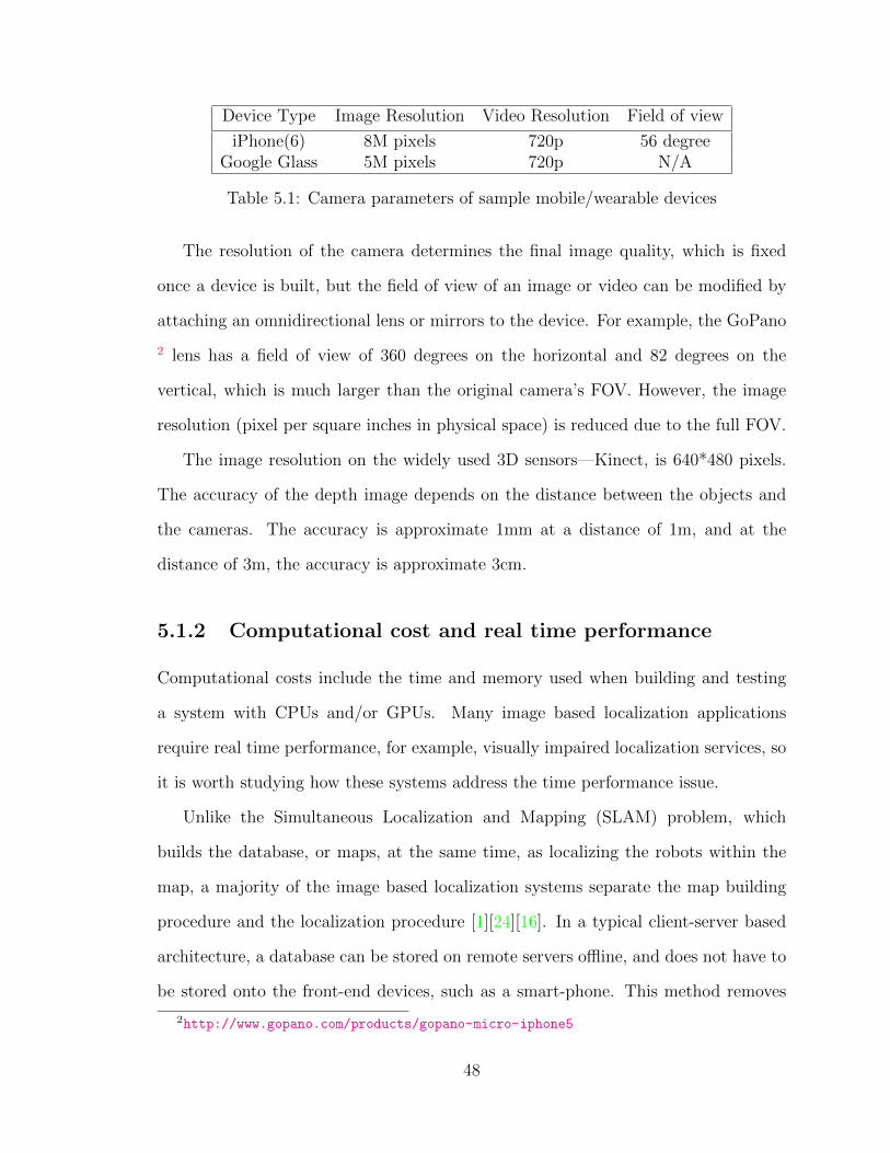
Device Type Image Resolution Video Resolution Field of view
iPhone(6) 8M pixels 720p 56 degreeGoogle Glass 5M pixels 720p N/A
Table 5.1: Camera parameters of sample mobile/wearable devices
The resolution of the camera determines the final image quality, which is fixed
once a device is built, but the field of view of an image or video can be modified by
attaching an omnidirectional lens or mirrors to the device. For example, the GoPano
2 lens has a field of view of 360 degrees on the horizontal and 82 degrees on the
vertical, which is much larger than the original camera’s FOV. However, the image
resolution (pixel per square inches in physical space) is reduced due to the full FOV.
The image resolution on the widely used 3D sensors—Kinect, is 640*480 pixels.
The accuracy of the depth image depends on the distance between the objects and
the cameras. The accuracy is approximate 1mm at a distance of 1m, and at the
distance of 3m, the accuracy is approximate 3cm.
5.1.2 Computational cost and real time performance
Computational costs include the time and memory used when building and testing
a system with CPUs and/or GPUs. Many image based localization applications
require real time performance, for example, visually impaired localization services, so
it is worth studying how these systems address the time performance issue.
Unlike the Simultaneous Localization and Mapping (SLAM) problem, which
builds the database, or maps, at the same time, as localizing the robots within the
map, a majority of the image based localization systems separate the map building
procedure and the localization procedure [1][24][16]. In a typical client-server based
architecture, a database can be stored on remote servers offline, and does not have to
be stored onto the front-end devices, such as a smart-phone. This method removes
2http://www.gopano.com/products/gopano-micro-iphone5
48
the memory storage constraints of the mobile devices, a majority of which have
limited storage.
In a vision-based localization system, the contents stored in the database are image
features or point clouds. Instead of storing the original 2D images and videos, storing
features of them can save a lot of memory space. Also it makes localization solutions
scalable; thus, can extend the covered area from a single floor of a small building to
multiple buildings, or even a city [45].
For some localization applications, such as assistive localization for the blind,
real-time performance is one of the most critical requirements. Though not so many
researchers have implemented all components of an assistive localization system, there
are few systems which can achieve querying within seconds. For example, Altwaijry
[1] uses Google Glass to implement the system and can retrieve a result in roughly 2
to 4 seconds on the Verizon LTE network.
5.1.3 System evaluation
The criteria to evaluate a localization system mainly depends on how such a system
works. Some researchers choose to encode location information into man-made color
markers [27]. Others develop localization systems and serve visually impaired people
by providing instructions for their next moves based on current locations [30] [23]
[12]. However, the majority of researchers choose to provide current coordinates of a
device on a 2D map or in a 3D coordinate system. In this section, we will discuss the
performance of working localization systems based on three perspectives: database
usage, time usage, and retrieval accuracy.
Researches using different databases are evaluated. Some of the databases are
benchmark databases 3 and the others are self-collected databases [14] [48]. To eval-
uate a localization algorithm, we need to consider the database from several perspec-
3http://www.robots.ox.ac.uk/NewCollegeData/
49
tives: 1) number of databases tested; 2) the size of each database; 3) selections of
training data and testing data within a database; 4) the heterogeneity of the database
(omnidirectional images and/or perspective images); and 5) the consecutiveness of the
database (discrete images or videos streams).
A majority of existing systems use the same images types for building and queying
databases; however, some of the image types in querying could be different in some
other systems. Lourenco [25] uses omnidirectional images to build a database and uses
normal perspective images to query the database. Using omnidirectional images to
query a database which is built with perspective images is also theoretically possible.
Time performance and retrieval accuracy are usually evaluated together. In a
typical evaluating process, we need several considerations: 1) whether a single GPU
or multiple GPUs are used; 2) ideally every new input image should have at least one
exact corresponding image in a database, however, as camera position and posture
differs, one-to-one matching is usually not the case. A definition of accuracy tolerance
is required. All matches within the tolerance threshold are treated as correct matches.
For example, the tolerance matches can be distance tolerated [33] [15]; and 3) the
matching results are usually ranked according to a similarity measure. The result
with the smallest similarity distance is usually considered the correct one; however,
this is not always the case. In practice, researchers have considered the first few
matches as the correct candidates. The number of accepted matches can vary among
researchers, e.g. 5, 10, 20, or 40 [33].
5.2 Emerging technologies
Two emerging technologies are discussed in this section. First, as mobile devices be-
come more powerful, localization systems can be partially or completely implemented
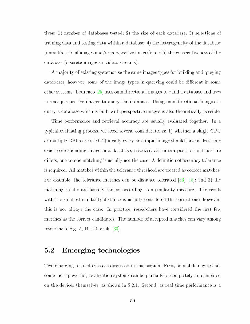
on the devices themselves, as shown in 5.2.1. Second, as real time performance is a
50
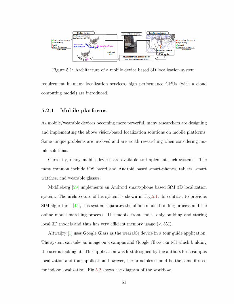
Figure 5.1: Architecture of a mobile device based 3D localization system.
requirement in many localization services, high performance GPUs (with a cloud
computing model) are introduced.
5.2.1 Mobile platforms
As mobile/wearable devices becoming more powerful, many researchers are designing
and implementing the above vision-based localization solutions on mobile platforms.
Some unique problems are involved and are worth researching when considering mo-
bile solutions.
Currently, many mobile devices are available to implement such systems. The
most common include iOS based and Android based smart-phones, tablets, smart
watches, and wearable glasses.
Middleberg [29] implements an Android smart-phone based SfM 3D localization
system. The architecture of his system is shown in Fig.5.1. In contrast to previous
SfM algorithms [45], this system separates the offline model building process and the
online model matching process. The mobile front end is only building and storing
local 3D models and thus has very efficient memory usage (< 5M).
Altwaijry [1] uses Google Glass as the wearable device in a tour guide application.
The system can take an image on a campus and Google Glass can tell which building
the user is looking at. This application was first designed by the authors for a campus
localization and tour application; however, the principles should be the same if used
for indoor localization. Fig.5.2 shows the diagram of the workflow.
51

(a) Diagram of using Glass to do a tour guide application
(b) An visual overview of major components of a Google Glass
Figure 5.2: The Google Glass based tour guide application.
Paisios [39] uses an Android phone and implements a wireless based application
for a localization interface in an indoor environment. The author, himself, is a blind
person, and the interface is tested by him and other members in the blind community.
Fig.5.3 is his interface.
Shen [47] proposes a smart-phone interface for image based localization, as shown
in Fig.5.4. The users taps a video preview window to transmit an image to a remote
server, and the server searches the database and returns a map and the corresponding
location of the user on this map.
52
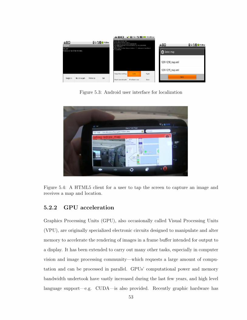
Figure 5.3: Android user interface for localization
Figure 5.4: A HTML5 client for a user to tap the screen to capture an image andreceives a map and location.
5.2.2 GPU acceleration
Graphics Processing Units (GPU), also occasionally called Visual Processing Units
(VPU), are originally specialized electronic circuits designed to manipulate and alter
memory to accelerate the rendering of images in a frame buffer intended for output to
a display. It has been extended to carry out many other tasks, especially in computer
vision and image processing community—which requests a large amount of compu-
tation and can be processed in parallel. GPUs’ computational power and memory
bandwidth undertook have vastly increased during the last few years, and high level
language support—e.g. CUDA—is also provided. Recently graphic hardware has
53
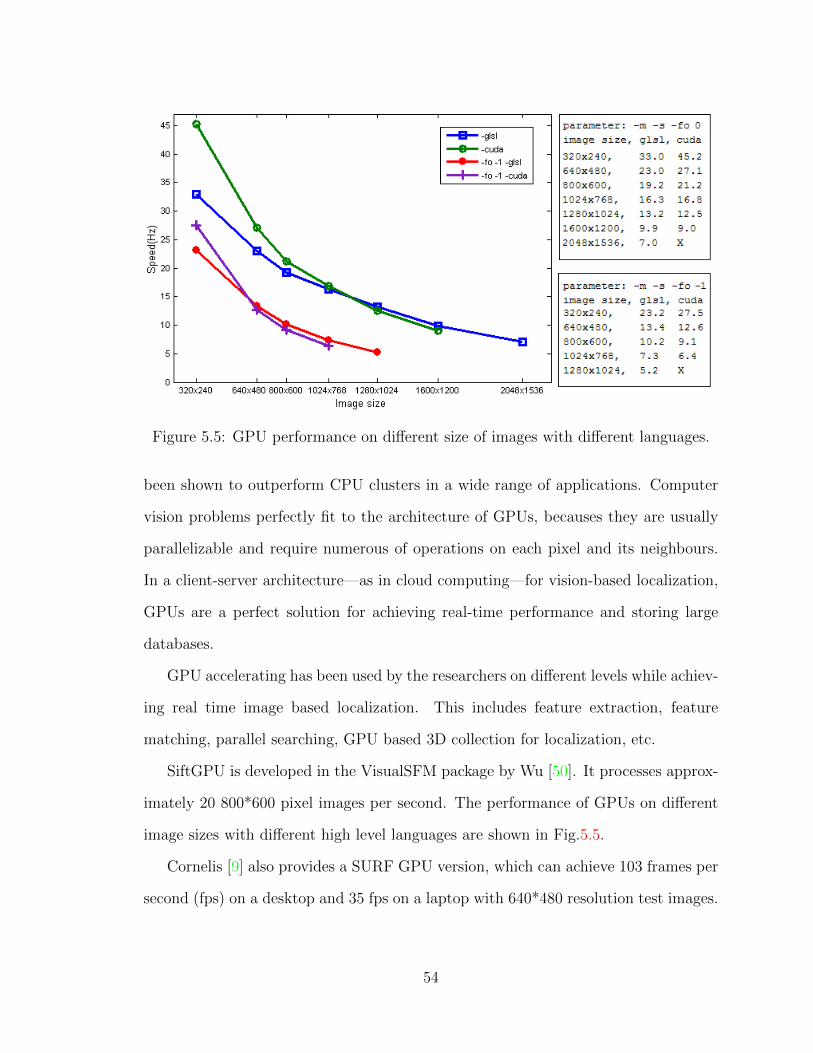
Figure 5.5: GPU performance on different size of images with different languages.
been shown to outperform CPU clusters in a wide range of applications. Computer
vision problems perfectly fit to the architecture of GPUs, becauses they are usually
parallelizable and require numerous of operations on each pixel and its neighbours.
In a client-server architecture—as in cloud computing—for vision-based localization,
GPUs are a perfect solution for achieving real-time performance and storing large
databases.
GPU accelerating has been used by the researchers on different levels while achiev-
ing real time image based localization. This includes feature extraction, feature
matching, parallel searching, GPU based 3D collection for localization, etc.
SiftGPU is developed in the VisualSFM package by Wu [50]. It processes approx-
imately 20 800*600 pixel images per second. The performance of GPUs on different
image sizes with different high level languages are shown in Fig.5.5.
Cornelis [9] also provides a SURF GPU version, which can achieve 103 frames per
second (fps) on a desktop and 35 fps on a laptop with 640*480 resolution test images.
54
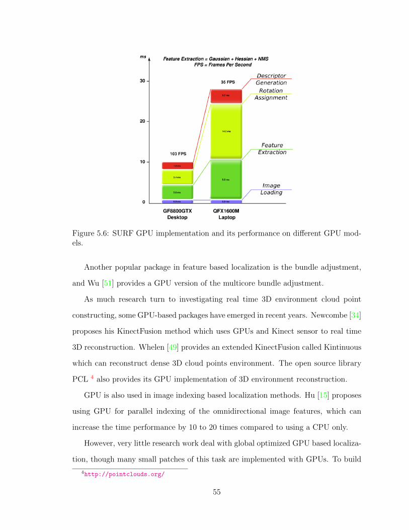
Figure 5.6: SURF GPU implementation and its performance on different GPU mod-els.
Another popular package in feature based localization is the bundle adjustment,
and Wu [51] provides a GPU version of the multicore bundle adjustment.
As much research turn to investigating real time 3D environment cloud point
constructing, some GPU-based packages have emerged in recent years. Newcombe [34]
proposes his KinectFusion method which uses GPUs and Kinect sensor to real time
3D reconstruction. Whelen [49] provides an extended KinectFusion called Kintinuous
which can reconstruct dense 3D cloud points environment. The open source library
PCL 4 also provides its GPU implementation of 3D environment reconstruction.
GPU is also used in image indexing based localization methods. Hu [15] proposes
using GPU for parallel indexing of the omnidirectional image features, which can
increase the time performance by 10 to 20 times compared to using a CPU only.
However, very little research work deal with global optimized GPU based localiza-
tion, though many small patches of this task are implemented with GPUs. To build
4http://pointclouds.org/
55

a visually impaired people localization solution, a real time performance is one of the
key requirements, as the users usually will lose patience if the system is too slow.
56
Chapter 6
Conclusions and Discussions
This literature review discusses the state-of-the-art methods and systems in vision-
based indoor localization. Based on whether 3D estimation/reconstruction is re-
quired, the methods are classified into 2D approaches and 3D approaches. The work-
flows in each category are analyzed and representative research work are surveyed.
Many vision based localization methods use 2D image approaches. Visual repre-
sentation of the 3D physical world is constructed by collecting 2D images or video
sequences, features on input images are extracted and matched into 2D maps or 3D
coordinate systems. To extract features from one single omnidirectional image, dif-
ferent kinds of local features and/or global features used. For example, local features
include SIFT, SURF, etc, and global features include GIST, omnidirectional global
structure descriptor, etc. To better use the feature distribution information among
a single image, local features can be pooled together, e.g. by using Fisher Vector, or
Bag of Words, and represent the image with these pooled representation. When a
new omnidirectional image is given into the system, its extracted features are used
as query keys and searched in the database. The related geolocation of the image is
output as the location result.
57
Depending on how the 3D data are acquired, 3D approaches can be classified as
Structure from Motion(SfM) based method, and direct 3D sensor based method. SfM
methods use 2D images either from the Web or self-collected sources, and construct
3D models up to a scale. New images are matched with the constructed 3D mod-
els. Many researchers also provide several solutions to resolve the scale with extra
knowledge of the environment. As the 3D acquisition devices are becoming cheaper
and more popular, another method which uses 3D information to do the vision based
localization tasks attracts more and more attentions. The 3D sensor based methods
construct 3D environments directly from depth sensors, such as Microsoft Kinect or
ASUS Xtion RGB-D sensors in real-time, without using any vision algorithms. The
new input 3D local information of the users are matched with existed global models
and thus determine users locations.
Due to the requirement of the portable and rea- time performance of a wearable
localization service, two emerging technologies, mobile computing and GPU accel-
eration, are discussed in this review. Mobile computing is emerging due to the re-
cent development of mobile devices, such as smart-phones (iPhones, Android Phones,
etc), or wearable devices (Google Glass, Apple Watch, etc.). These devices are light,
portable, and at the same time have strong computation power as well as adequate
sensors. The human computer interfaces are also becoming more and more natural.
These make a effective and convenient vision based localization service possible. As
the scale of the database increase, real time searching of the database is becoming
harder by using just one single CPU, so GPUs are becoming popular in achieving a
real time localization solution with a client-server cloud computing architecture. By
combining the mobile computing and server-side GPU acceleration, the vision-based
localization service has significant potential to improve.
There are a few lines of future work which can be done. Omnidirectional vision
based mobile front end plus GPU-enabled server end can work together by query-
58

ing large scale pre-built geo-located database to provide an accurate and real time
localization service. Different map building techniques, feature extraction or image
representation methods, and search methods can combine together to achieve an opti-
mal solution. GPU acceleration techniques can be involved in these steps,and achieve
a global optimized computation solution to achieve a real time performance.
59
Acknowledgements
This material is based upon work supported by the National Science Foundation under
Grant No. 11337172. Any opinions, findings, and conclusions or recommendations
expressed in this material are those of the author(s) and do not necessarily reflect the
views of the National Science Foundation.
I would like to thank my advisor Professor Zhigang Zhu for his insightful sug-
gestions in forming the review topics and his continuous support during the review
writing process. The author would like to thank the committee members Professors
Jizhong Xiao and Jianting Zhang for their professional and helpful comments and
suggestions. The author would like to thank Martin Goldberg for his proofreading.
The author would also like to thank all the CcvcL lab members who have had many
discussions with me and provide supports and encouragement during the writing of
this survey, in many different ways.
60
Bibliography
[1] Hani Altwaijry, Mohammad Moghimi, and Serge Belongie. Recognizing locationswith google glass: A case study. In IEEE Winter Conference on Applications ofComputer Vision (WACV), Steamboat Springs, Colorado, March 2014.
[2] Samreen Anjum. Place recognition for indoor navigation. http:
//www.cs.cmu.edu/afs/cs/user/mjs/ftp/thesis-program/2011/theses/
qatar-anjum.pdf. Last visited 01/20/2015.
[3] Relja Arandjelovic and Andrew Zisserman. All about vlad. In Computer Visionand Pattern Recognition (CVPR), 2013 IEEE Conference on, pages 1578–1585.IEEE, 2013.
[4] Herbert Bay, Tinne Tuytelaars, and Luc Van Gool. Surf: Speeded up robustfeatures. In Computer Vision–ECCV 2006, pages 404–417. Springer, 2006.
[5] Joydeep Biswas and Manuela Veloso. Depth camera based indoor mobile robotlocalization and navigation. In Robotics and Automation (ICRA), 2012 IEEEInternational Conference on, pages 1697–1702. IEEE, 2012.
[6] A. Bosch, A. Zisserman, and X. Muoz. Image classification using random forestsand ferns. In Computer Vision, 2007. ICCV 2007. IEEE 11th InternationalConference on, pages 1–8, Oct 2007.
[7] Alexandre Chapoulie, Patrick Rives, and David Filliat. Appearance-based seg-mentation of indoors/outdoors sequences of spherical views. In Intelligent Robotsand Systems (IROS), 2013 IEEE/RSJ International Conference on, pages 1946–1951. IEEE, 2013.
[8] Sakmongkon Chumkamon, Peranitti Tuvaphanthaphiphat, and Phongsak Keer-atiwintakorn. A blind navigation system using rfid for indoor environments.In Electrical Engineering/Electronics, Computer, Telecommunications and In-formation Technology, 2008. ECTI-CON 2008. 5th International Conference on,volume 2, pages 765–768. IEEE, 2008.
[9] Nico Cornelis and Luc Van Gool. Fast scale invariant feature detection andmatching on programmable graphics hardware. In Computer Vision and PatternRecognition Workshops, 2008. CVPRW’08. IEEE Computer Society Conferenceon, pages 1–8. IEEE, 2008.
61
[10] Mark Cummins and Paul Newman. Fab-map: Probabilistic localization andmapping in the space of appearance. The International Journal of RoboticsResearch, 27(6):647–665, 2008.
[11] J De Carufel and Robert Laganiere. Matching cylindrical panorama sequencesusing planar reprojections. In Computer Vision Workshops (ICCV Workshops),2011 IEEE International Conference on, pages 320–327. IEEE, 2011.
[12] Wael Elloumi, Kamel Guissous, Aladine Chetouani, Raphael Canals, RemyLeconge, Bruno Emile, and Sylvie Treuillet. Indoor navigation assistance with asmartphone camera based on vanishing points. In Indoor Positioning and IndoorNavigation (IPIN), 2013 International Conference on, pages 1–9. IEEE, 2013.
[13] Li Fei-Fei and Pietro Perona. A bayesian hierarchical model for learning naturalscene categories. In Computer Vision and Pattern Recognition, 2005. CVPR2005. IEEE Computer Society Conference on, volume 2, pages 524–531. IEEE,2005.
[14] Micha l Grega and Seweryn Lach. Urban photograph localization using the in-street applicationaccuracy and performance analysis. Multimedia Tools and Ap-plications, pages 1–12, 2013.
[15] Feng Hu, Zhigang Zhu, and Jianting Zhang. Mobile panoramic vision for blindnavigation via indexing and localization. Workshop on Assistive Computer Vi-sion and Robotics, ECCV2014, 2014.
[16] Arnold Irschara, Christopher Zach, J-M Frahm, and Horst Bischof. Fromstructure-from-motion point clouds to fast location recognition. In ComputerVision and Pattern Recognition, 2009. CVPR 2009. IEEE Conference on, pages2599–2606. IEEE, 2009.
[17] Daisuke Ishizuka, Atsushi Yamashita, Ryosuke Kawanishi, Toru Kaneko, andHajime Asama. Self-localization of mobile robot equipped with omnidirectionalcamera using image matching and 3d-2d edge matching. In Computer VisionWorkshops (ICCV Workshops), 2011 IEEE International Conference on, pages272–279. IEEE, 2011.
[18] Herve Jegou, Matthijs Douze, Cordelia Schmid, and Patrick Perez. Aggregat-ing local descriptors into a compact image representation. In Computer Visionand Pattern Recognition (CVPR), 2010 IEEE Conference on, pages 3304–3311.IEEE, 2010.
[19] EdwardDavid Johns and Guang-Zhong Yang. Pairwise probabilistic voting: Fastplace recognition without ransac. In David Fleet, Tomas Pajdla, Bernt Schiele,and Tinne Tuytelaars, editors, Computer Vision ECCV 2014, volume 8690of Lecture Notes in Computer Science, pages 504–519. Springer InternationalPublishing, 2014.
62
[20] Ryosuke Kawanishi, Atsushi Yamashita, and Toru Kaneko. Estimation of cam-era motion with feature flow model for 3d environment modeling by usingomni-directional camera. In Intelligent Robots and Systems, 2009. IROS 2009.IEEE/RSJ International Conference on, pages 3089–3094. IEEE, 2009.
[21] Hiroshi Koyasu, Hitoshi Maekawa, Hiroshi Kawasaki, Shintaro Ono, and Kat-sushi Ikeuchi. Scan-matching based 6dof SLAM using omnidirectional stereo.In Proceedings of the 13. IAPR International Conference on Machine VisionApplications, MVA 2013, Kyoto, Japan, May 20-23, 2013, pages 306–310, 2013.
[22] Hideyuki Kume, Arne Suppe, and Takeo Kanade. Vehicle localization along apreviously driven route using an image database. IAPR International Conferenceon Machine Vision Applications. Kyoto, JAPAN. 2013.
[23] Young Hoon Lee and Gerard Medioni. Wearable rgbd indoor navigation sys-tem for the blind. In Workshop on Assistive Computer Vision and Robotics,ECCV2014. IEEE, 2014.
[24] Yunpeng Li, Noah Snavely, and Daniel P Huttenlocher. Location recognitionusing prioritized feature matching. In ECCV 2010, pages 791–804. Springer,2010.
[25] Miguel Lourenco, Vitor Pedro, and Joao Pedro Barreto. Localization in indoorenvironments by querying omnidirectional visual maps using perspective images.In Robotics and Automation (ICRA), 2012 IEEE International Conference on,pages 2189–2195. IEEE, 2012.
[26] David G Lowe. Distinctive image features from scale-invariant keypoints. Inter-national journal of computer vision, 60(2):91–110, 2004.
[27] Roberto Manduchi. Mobile vision as assistive technology for the blind: An ex-perimental study. The 13th Int. Conf. on Computers Helping People of SpecialNeeds (ICCHP 2012), Springer, 2012.
[28] Branislav Micusık, Daniel Martinec, and Tomas Pajdla. 3d metric reconstructionfrom uncalibrated omnidirectional images. In Proceedings of the Asian Confer-ence on Computer Vision (ACCV), volume 1, pages 545–550, 2003.
[29] Sven Middelberg, Torsten Sattler, Ole Untzelmann, and Leif Kobbelt. Scalable6-dof localization on mobile devices. ECCV 2014, pages 268–283, 2014.
[30] Edgardo Molina, Zhigang Zhu, and Yingli Tian. Visual nouns for indoor/outdoornavigation. The 13th Int. Conf. on Computers Helping People of Special Needs(ICCHP 2012), Springer, 2012.
[31] AC Murillo, Carlos Sagues, Jose Jesus Guerrero, Toon Goedeme, Tinne Tuyte-laars, and Luc Van Gool. From omnidirectional images to hierarchical localiza-tion. Robotics and Autonomous Systems, 55(5):372–382, 2007.
63
[32] Ana Cris Murillo, Jose Jesus Guerrero, and C Sagues. Surf features for efficientrobot localization with omnidirectional images. In Robotics and Automation,2007 IEEE International Conference on, pages 3901–3907. IEEE, 2007.
[33] Ana Cristina Murillo, Gautam Singh, Jana Kosecka, and Jose Jesus Guerrero.Localization in urban environments using a panoramic gist descriptor. Robotics,IEEE Transactions on, 29(1):146–160, 2013.
[34] Richard A Newcombe, Andrew J Davison, Shahram Izadi, Pushmeet Kohli, Ot-mar Hilliges, Jamie Shotton, David Molyneaux, Steve Hodges, David Kim, andAndrew Fitzgibbon. Kinectfusion: Real-time dense surface mapping and track-ing. In Mixed and augmented reality (ISMAR), 2011 10th IEEE internationalsymposium on, pages 127–136. IEEE, 2011.
[35] Snavely Noah. Bundler: Structure from motion (sfm) for unordered imagecollections. http://www.cs.cornell.edu/~snavely/bundler/. Last visited01/20/2015.
[36] Aude Oliva and Antonio Torralba. Modeling the shape of the scene: A holisticrepresentation of the spatial envelope. International journal of computer vision,42(3):145–175, 2001.
[37] Alain Pagani and Didier Stricker. Structure from motion using full sphericalpanoramic cameras. In Computer Vision Workshops (ICCV Workshops), 2011IEEE International Conference on, pages 375–382. IEEE, 2011.
[38] Nektarios Paisios. Mobile Accessibility Tools for the Visually Impaired. PhDthesis, New York University, 2012.
[39] Nektarios Paisios, Alex Rubinsteyn, Lakshminarayanan Subramanian, MattTierney, and Vrutti Vyas. Tracking indoor location and motion for navigationalassistance. In Proceedings of the 24th annual ACM symposium adjunct on Userinterface software and technology, pages 83–84. ACM, 2011.
[40] Florent Perronnin, Jorge Sanchez, and Thomas Mensink. Improving the fisherkernel for large-scale image classification. In Computer Vision–ECCV 2010,pages 143–156. Springer, 2010.
[41] Kuemmerle Rainer, Grisetti Giorgio, Strasdat Hauke, Konolige Kurt, and Bur-gard Wolfram. g2o: A general framework for graph optimization. https:
//openslam.org/g2o.html. Last visited 01/20/2015.
[42] Jose Rivera-Rubio, Saad Idrees, Ioannis Alexiou, Lucas Hadjilucas, and Anil ABharath. Mobile visual assistive apps: Benchmarks of vision algorithm perfor-mance. In New Trends in Image Analysis and Processing–ICIAP 2013, pages30–40. Springer, 2013.
64
[43] Torsten Sattler, Bastian Leibe, and Leif Kobbelt. Fast image-based localiza-tion using direct 2d-to-3d matching. In Computer Vision (ICCV), 2011 IEEEInternational Conference on, pages 667–674. IEEE, 2011.
[44] Torsten Sattler, Bastian Leibe, and Leif Kobbelt. Improving image-based local-ization by active correspondence search. In ECCV 2012, pages 752–765. Springer,2012.
[45] Torsten Sattler, Bastian Leibe, and Leif Kobbelt. Towards fast image-based lo-calization on a city-scale. In Outdoor and Large-Scale Real-World Scene Analysis,pages 191–211. Springer, 2012.
[46] Torsten Sattler, Tobias Weyand, Bastian Leibe, and Leif Kobbelt. Image retrievalfor image-based localization revisited. In BMVC, volume 6, page 7, 2012.
[47] Ju Shen and Wai-tian Tan. Image-based indoor place-finder using image to planematching. In Multimedia and Expo (ICME), 2013 IEEE International Conferenceon, pages 1–6. IEEE, 2013.
[48] Dwaipayan Sinha, Mirza Tahir Ahmed, and Michael Greenspan. Image retrievalusing landmark indexing for indoor navigation. In Computer and Robot Vision(CRV), 2014 Canadian Conference on, pages 63–70. IEEE, 2014.
[49] Thomas Whelan, Michael Kaess, Maurice Fallon, Hordur Johannsson, JohnLeonard, and John McDonald. Kintinuous: Spatially extended kinectfusion.RSS 2012 Workshop on RGB-D Cameras. 2012.
[50] Changchang Wu. VisualSFM : A visual structure from motion system. http:
//ccwu.me/vsfm/. Last visited 01/20/2015.
[51] Changchang Wu. Towards linear-time incremental structure from motion. In3DTV-Conference, 2013 International Conference on, pages 127–134. IEEE,2013.
[52] Xiaodong Yang and YingLi Tian. Action recognition using super sparse codingvector with spatio-temporal awareness. ECCV 2014, pages 727–741, 2014.
[53] Xinnan Yu and Yu-Jin Zhang. A 2d histogram representation of images forpooling., Proc. SPIE 7877, Image Processing: Machine Vision Applications. 2011.
[54] Dong Zhang, Dah-Jye Lee, and Brandon Taylor. Seeing eye phone: a smartphone-based indoor localization and guidance system for the visually impaired.Machine vision and applications, 25(3):811–822, 2014.
65